Embed Size (px)
Citation preview
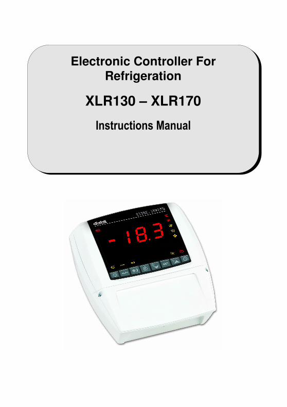
Electronic Controller For Refrigeration
XLR130 – XLR170
Instructions Manual
dIXELdIXELdIXELdIXEL Installing and Operating Instructions rel.rel.rel.rel.2222.0 .0 .0 .0 ---- cod. 1592017000 cod. 1592017000 cod. 1592017000 cod. 1592017000
1592017000 XLR 130-170 GB r2.0 08.09.2006.doc XL130 - XLR170 2/19
CCCCOOLOOLOOLOOLMMMMATEATEATEATE
XLR130CXLR130CXLR130CXLR130C –––– XLR170CXLR170CXLR170CXLR170C
INDEX To translate this manual in you language you can start from the manual of XW570L code: “1592009130 XW570L GB.doc” and translate the part in RED colour.
1. GENERAL WARNING 3
2. GENERAL DESCRIPTION 3
3. CONTROLLING LOADS 3
4. KEYBOARD 5
5. REAL TIME CLOCK FUNCTION – ONLY FOR INSTRUMENTS WITH RTC 8
6. PARAMETER LIST 8
7. DIGITAL INPUTS 11
8. INSTALLATION AND MOUNTING 12
9. DIMENSIONS 14
10. ELECTRICAL CONNECTIONS 14
11. TTL SERIAL LINE 14
12. HOW TO USE THE HOT KEY 14
13. ALARM SIGNALS 15
14. TECHNICAL DATA 15
15. CONNECTIONS 16
16. DEFAULT SETTING VALUES 17
dIXELdIXELdIXELdIXEL Installing and Operating Instructions rel.rel.rel.rel.2222.0 .0 .0 .0 ---- cod. 1592017000 cod. 1592017000 cod. 1592017000 cod. 1592017000
1592017000 XLR 130-170 GB r2.0 08.09.2006.doc XL130 - XLR170 3/19
1. GENERAL WARNING
1.1 PLEASE READ BEFORE USING THIS MANUAL
• This manual is part of the product and should be kept near the instrument for easy and quick reference.
• The instrument shall not be used for purposes different from those described hereunder. It cannot be used as a safety device.
• Check the application limits before proceeding.
1.2 SAFETY PRECAUTIONS
• Check the supply voltage is correct before connecting the instrument.
• Do not expose to water or moisture: use the controller only within the operating limits avoiding sudden temperature changes with high atmospheric humidity to prevent formation of condensation
• Warning: disconnect all electrical connections before any kind of maintenance.
• Fit the probe where it is not accessible by the End User. The instrument must not be opened.
• In case of failure or faulty operation send the instrument back to the distributor or to “Dixell S.p.A.” (see address) with a detailed description of the fault.
• Consider the maximum current which can be applied to each relay (see Technical Data).
• Ensure that the wires for probes, loads and the power supply are separated and far enough from each other, without crossing or intertwining.
• In case of applications in industrial environments, the use of mains filters (our mod. FT1) in parallel with inductive loads could be useful.
2. GENERAL DESCRIPTION
Models XLR130 and XLR170, 210x230mm format, are microprocessor based controllers suitable for applications on medium or low temperature refrigerating units. They are provided with four (XLR130) or six (XLR170) relay outputs to control compressor, defrost - which can be either electrical or hot gas (XLR170) - the evaporator fans (XLR170), the lights, the alarm and an auxiliary output. They are also provided with three NTC or PTC probe inputs, one for temperature control, one to control the defrost end temperature of the evaporator and the third, optional, for the display. There are two digital inputs (free contact) for the door switch and configurable by parameter. The standard TTL output allows the user to connect, by means of a TTL/RS485 external module, a ModBUS-RTU compatible monitoring system and to programme the parameter list with the “Hot Key”. Each model in the XLR100 can be provided with a Real Time Clock which allows programming of up to eight daily defrost cycles, divided into holidays and workdays. A “Day and Night” function with two different set points is fitted for energy saving.
3. CONTROLLING LOADS
3.1 THE COMPRESSOR
The regulation is performed according to the temperature measured by the thermostat probe with a positive differential from the set point: if the temperature increases and reaches set point plus differential the compressor is started and then turned off when the temperature reaches the set point value again. In case of fault in the thermostat probe the start and stop of the compressor are timed through parameters “COn” and “COF”.
3.2 FAST FREEZING
When defrost is not in progress, it can be activated the keypad by holding the oooo key pressed for about 3 seconds. The compressor operates in continuous mode for the time set through the “CCt” parameter. The cycle can be terminated before the end of the set time using the same activation
key, oooo for about 3 seconds.
3.3 DEFROST
3.3.1 XLR130 – TIMED DEFROST
The defrost interval is controlled by means of parameter “EdF”: - with EdF=in the defrost is made every “IdF” time, - with EdF=Sd the interval “IdF” is calculate through Smart Defrost algorithm (the counter is increased only when the compressor is ON). - with real time clock present EdF can be set to “rtc”, In this case, the defrost is made in real time depending on the hours set in the parameters
Ld1..Ld8 on workdays and in Sd1…Sd8 in holidays; Defrost is performed through a simple stop of the compressor. Parameter “IdF” controls the interval between defrost cycles, while its length is controlled by parameter “MdF”.
3.3.2 XLR170 – HEATER OR HOT GAS DEFROST
Three defrost modes are available through the “tdF” parameter: defrost with electrical heater (tdF=rE), hot gas (tdF=in), or thermostatic defrost(tdF=rt). The defrost interval is controlled by means of parameter “EdF”:
dIXELdIXELdIXELdIXEL Installing and Operating Instructions rel.rel.rel.rel.2222.0 .0 .0 .0 ---- cod. 1592017000 cod. 1592017000 cod. 1592017000 cod. 1592017000
1592017000 XLR 130-170 GB r2.0 08.09.2006.doc XL130 - XLR170 4/19
- with EdF=in the defrost is made every “IdF” time, - with EdF=Sd the interval “IdF” is calculate through Smart Defrost algorithm (the counter is increased only when the compressor is ON). - with real time clock present EdF can be set to “rtc”. In this case, the defrost is made in real time depending on the hours set in the parameters
Ld1..Ld8 on workdays and in Sd1…Sd8 in holidays; At the end of defrost the drip time is controlled through the “Fdt” parameter.
3.4 CONTROL OF EVAPORATOR FANS (XLR170 OR XLR130 WITH OA1=FAN)
The fan control mode is selected by means of the “FnC” parameter: C-n fans will switch ON and OFF with the compressor and not run during defrost; C-y fans will switch ON and OFF with the compressor, also during defrost
After defrost, there is a timed fan delay allowing for drip time, set by means of the “Fnd” parameter. O-n fans will run continuously and not run during defrost; O-y fans will run continuously also during defrost
An additional parameter “FSt” provides the setting of temperature, detected by the evaporator probe, above which the fans are always OFF. This can be used to make sure circulation of air only if his temperature is lower than set in “FSt”.
3.5 AUXILIARY OUTPUT CONFIGURATION - TERM. 15-16, PAR. OA1
The functioning of the auxiliary relay (terminals. 15-16) can be set by the oA1 parameter, according to the kind of application. In the following paragraph the possible setting:
3.5.1 XLR130: forced air application, normal temperature -oA1= Fan Parameters involved:
- FnC Fan operating mode; - Fnd Fan delay after a defrost - FSt Fan stop temperature; - FAP Probe for fan management
With this setting the auxiliary relay works as fan relay. See par. 3.4 “Control of evaporator fans”. NOTE: if FAP = nP (no probe), the relay will be activated according to the setting of FnC parameter independently from the temperature of evaporator.
3.5.2 Auxiliary relay - oA1= AUS
With oA1=AUS, two kinds of working are available. A. The AUX relay is activated only by keyboard Set oA1 =AUS and ArP= nP (no probe for auxiliary output). In this case the relay 15-16 can be activated only by pushing the AUX button of the keyboard. B. Auxiliary thermostat (I.E.. anti condensing heater) with the possibility of switching it on and off also by keyboard Parameters involved:
- ACH Kind of regulation for the auxiliary relay: heating /cooling; - SAA Set point for auxiliary relay - ArP Probe for auxiliary relay
By means of these 3 parameters the functioning of the auxiliary relay can be set.. The differential is given by the Hy parameter. The auxiliary relay can be switched on also by the AUX button. In this case it remains on till it’s manually switched off. The defrost doesn’t affect the status of auxiliary relay.
3.5.3 on/off relay - oA1 = onF
In this case the relay is activated when the controller is turned on and de-activated when the controller is turned off..
3.5.4 XLR170: Second defrost relay for applications with 2 evaporators – oA1 = dF2 Parameters involved:
- dtS end defrost temperature for second defrost relay; - MdS maximum defrost duration for second defrost relay; - dSP probe selection for second defrost
With 2 evaporators the regulation restarts when both the defrosts are finished.
3.5.5 Second compressor – oA1 = cP2
In this case the controller can manage 2 compressors or a 2 step compressor. Functioning: the 2nd compressor is activated after the fist compressor with a delay set in the Ac1 parameter (seconds). Both compressor are turned off at the same time.
dIXELdIXELdIXELdIXEL Installing and Operating Instructions rel.rel.rel.rel.2222.0 .0 .0 .0 ---- cod. 1592017000 cod. 1592017000 cod. 1592017000 cod. 1592017000
1592017000 XLR 130-170 GB r2.0 08.09.2006.doc XL130 - XLR170 5/19
If cco=AL compressors are switched on by turn. Parameters involved:
- cco Compressor activation: type of sequence: by turn or in sequence; - Ac1 Second compressor activation delay (seconds);
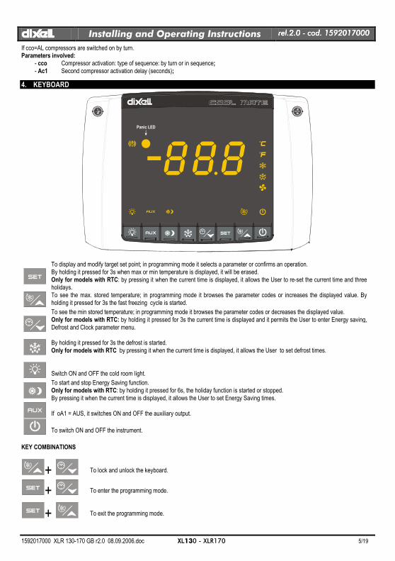
4. KEYBOARD
Panic LED
To display and modify target set point; in programming mode it selects a parameter or confirms an operation. By holding it pressed for 3s when max or min temperature is displayed, it will be erased. Only for models with RTC: by pressing it when the current time is displayed, it allows the User to re-set the current time and three holidays.
To see the max. stored temperature; in programming mode it browses the parameter codes or increases the displayed value. By holding it pressed for 3s the fast freezing cycle is started.
To see the min stored temperature; in programming mode it browses the parameter codes or decreases the displayed value. Only for models with RTC: by holding it pressed for 3s the current time is displayed and it permits the User to enter Energy saving, Defrost and Clock parameter menu.
By holding it pressed for 3s the defrost is started. Only for models with RTC by pressing it when the current time is displayed, it allows the User to set defrost times.
Switch ON and OFF the cold room light.
To start and stop Energy Saving function. Only for models with RTC: by holding it pressed for 6s, the holiday function is started or stopped. By pressing it when the current time is displayed, it allows the User to set Energy Saving times.
If oA1 = AUS, it switches ON and OFF the auxiliary output.
To switch ON and OFF the instrument.
KEY COMBINATIONS
+
To lock and unlock the keyboard.
+
To enter the programming mode.
+
To exit the programming mode.
dIXELdIXELdIXELdIXEL Installing and Operating Instructions rel.rel.rel.rel.2222.0 .0 .0 .0 ---- cod. 1592017000 cod. 1592017000 cod. 1592017000 cod. 1592017000
1592017000 XLR 130-170 GB r2.0 08.09.2006.doc XL130 - XLR170 6/19
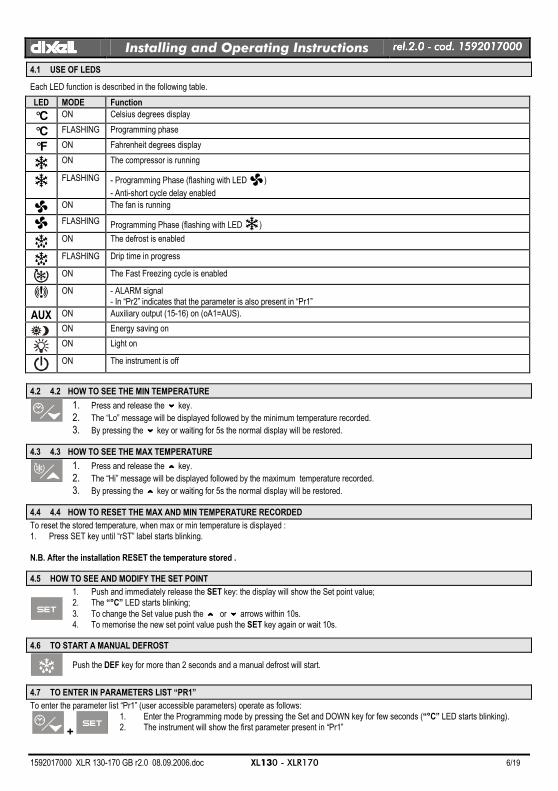
4.1 USE OF LEDS
Each LED function is described in the following table.
LED MODE Function
°C ON Celsius degrees display
°C FLASHING Programming phase
°F ON Fahrenheit degrees display
ON The compressor is running
FLASHING - Programming Phase (flashing with LED )
- Anti-short cycle delay enabled
ON The fan is running
FLASHING Programming Phase (flashing with LED )
ON The defrost is enabled
FLASHING Drip time in progress
ON The Fast Freezing cycle is enabled
ON - ALARM signal
- In “Pr2” indicates that the parameter is also present in “Pr1”
AUX ON Auxiliary output (15-16) on (oA1=AUS).
ON Energy saving on
ON Light on
ON The instrument is off
4.2 4.2 HOW TO SEE THE MIN TEMPERATURE
1. Press and release the nnnn key.
2. The “Lo” message will be displayed followed by the minimum temperature recorded. 3. By pressing the nnnn key or waiting for 5s the normal display will be restored.
4.3 4.3 HOW TO SEE THE MAX TEMPERATURE
1. Press and release the oooo key.
2. The “Hi” message will be displayed followed by the maximum temperature recorded. 3. By pressing the oooo key or waiting for 5s the normal display will be restored.
4.4 4.4 HOW TO RESET THE MAX AND MIN TEMPERATURE RECORDED
To reset the stored temperature, when max or min temperature is displayed : 1. Press SET key until “rST” label starts blinking. N.B. After the installation RESET the temperature stored .
4.5 HOW TO SEE AND MODIFY THE SET POINT
1. Push and immediately release the SET key: the display will show the Set point value; 2. The “°C” LED starts blinking;
3. To change the Set value push the o o o o or nnnn arrows within 10s. 4. To memorise the new set point value push the SET key again or wait 10s.
4.6 TO START A MANUAL DEFROST
Push the DEF key for more than 2 seconds and a manual defrost will start.
4.7 TO ENTER IN PARAMETERS LIST “PR1”
To enter the parameter list “Pr1” (user accessible parameters) operate as follows:
+
1. Enter the Programming mode by pressing the Set and DOWN key for few seconds (“°C” LED starts blinking). 2. The instrument will show the first parameter present in “Pr1”
dIXELdIXELdIXELdIXEL Installing and Operating Instructions rel.rel.rel.rel.2222.0 .0 .0 .0 ---- cod. 1592017000 cod. 1592017000 cod. 1592017000 cod. 1592017000
1592017000 XLR 130-170 GB r2.0 08.09.2006.doc XL130 - XLR170 7/19
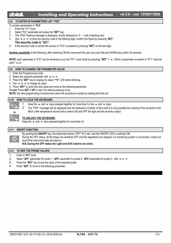
4.8 TO ENTER IN PARAMETERS LIST “PR2”
To access parameters in “Pr2”: 1. Enter the “Pr1” level. 2. Select “Pr2” parameter and press the “SET” key. 3. The “PAS” flashing message is displayed, shortly followed by “0 - -” with a flashing zero.
4. Use oooo or nnnn to input the security code in the flashing digit; confirm the figure by pressing “SET”.
The security code is “321“. 5. If the security code is correct the access to “Pr2” is enabled by pressing “SET” on the last digit. Another possibility is the following: after switching ON the instrument the user can push Set and DOWN keys within 30 seconds.
NOTE: each parameter in “Pr2” can be removed or put into “Pr1” (user level) by pressing “SET” + nnnn. When a parameter is present in “Pr1” “decimal point “ is on.
4.9 HOW TO CHANGE THE PARAMETER VALUE
1. Enter the Programming mode.
2. Select the required parameter with oooo or nnnn. 3. Press the “SET” key to display its value (“°C” LED starts blinking).
4. Use oooo or nnnn to change its value. 5. Press “SET” to store the new value and move to the following parameter. To exit: Press SET + UP or wait 15s without pressing a key. NOTE: the new programming is stored even when the procedure is exited by waiting the time-out.
4.10 HOW TO LOCK THE KEYBOARD
+
1. Keep the oooo and nnnn keys pressed together for more than 3 s the oooo and nnnn keys.
2. The “POF” message will be displayed and the keyboard is locked. At this point it is only possible the viewing of the set point or the MAX o Min temperature stored and to switch ON and OFF the light and the auxiliary output.
TO UNLOCK THE KEYBOARD
Keep the oooo and nnnn keys pressed together for more than 3s.
4.11 ON/OFF FUNCTION
By pushing the ON/OFF key, the instrument shows “OFF” for 5 sec. and the ON/OFF LED is switched ON. During the OFF status, all the relays are switched OFF and the regulations are stopped; if a monitoring system is connected, it does not record the instrument data and alarms. N.B. During the OFF status the Light and AUX buttons are active.
4.12 TO SEE THE PROBE VALUES
1. Enter in “Pr1” level.
2. Select “dP1” parameter for probe 1, “dP2” parameter for probe 2, “dP3” parameter for probe 3, with oooo or nnnn.
3. Press the “SET” key to see the value of the selected probe.
4. Press “SET” to move to the following parameter.
dIXELdIXELdIXELdIXEL Installing and Operating Instructions rel.rel.rel.rel.2222.0 .0 .0 .0 ---- cod. 1592017000 cod. 1592017000 cod. 1592017000 cod. 1592017000
1592017000 XLR 130-170 GB r2.0 08.09.2006.doc XL130 - XLR170 8/19
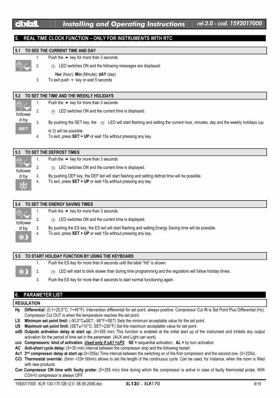
5. REAL TIME CLOCK FUNCTION – ONLY FOR INSTRUMENTS WITH RTC
5.1 TO SEE THE CURRENT TIME AND DAY
1. Push the nnnn key for more than 3 seconds
2. e LED switches ON and the following messages are displayed:
Hur (hour); Min (Minute); dAY (day)
3. To exit push n key or wait 5 seconds
5.2 TO SET THE TIME AND THE WEEKLY HOLIDAYS
followe
d by
1. Push the nnnn key for more than 3 seconds
2. e LED switches ON and the current time is displayed.
3. By pushing the SET key, the e LED will start flashing and setting the current hour, minutes, day and the weekly holidays (up
to 3) will be possible. 4. To exit, press SET + UP or wait 15s without pressing any key.
5.3 TO SET THE DEFROST TIMES
followe
d by
1. Push the nnnn key for more than 3 seconds
2. e LED switches ON and the current time is displayed.
3. By pushing DEF key, the DEF led will start flashing and setting defrost time will be possible. 4. To exit, press SET + UP or wait 15s without pressing any key.
5.4 TO SET THE ENERGY SAVING TIMES
followe
d by
1. Push the nnnn key for more than 3 seconds
2. e LED switches ON and the current time is displayed.
3. By pushing the ES key, the ES led will start flashing and setting Energy Saving time will be possible. 4. To exit, press SET + UP or wait 15s without pressing any key.
5.5 TO START HOLIDAY FUNCTION BY USING THE KEYBOARD
1. Push the ES key for more than 6 seconds until the label “Hd” is shown.
2. e LED will start to blink slower than during time programming and the regulators will follow holiday times.
3. Push the ES key for more than 6 seconds to start normal functioning again.
6. PARAMETER LIST
REGULATION
Hy Differential: (0,1÷25,5°C; 1÷45°F): Intervention differential for set point, always positive. Compressor Cut IN is Set Point Plus Differential (Hy). Compressor Cut OUT is when the temperature reaches the set point.
LS Minimum set point limit: (-50,0°C÷÷÷÷SET; -58°F÷SET) Sets the minimum acceptable value for the set point. US Maximum set point limit: (SET÷÷÷÷110°C; SET÷230°F) Set the maximum acceptable value for set point. odS Outputs activation delay at start up: (0÷255 min) This function is enabled at the initial start up of the instrument and inhibits any output
activation for the period of time set in the parameter. (AUX and Light can work) cco Compressors: kind of activation. Used only if oA1 =cP2: SE = sequential activation; AL = by turn activation AC Anti-short cycle delay: (0÷30 min) interval between the compressor stop and the following restart. Ac1 2nd compressor delay at start up (0÷255s) Time interval between the switching on of the first compressor and the second one. (0÷225s). CCt Thermostat override: (0min ÷23h 50min) allows to set the length of the continuous cycle. Can be used, for instance, when the room is filled
with new products. Con Compressor ON time with faulty probe: (0÷255 min) time during which the compressor is active in case of faulty thermostat probe. With
COn=0 compressor is always OFF.
dIXELdIXELdIXELdIXEL Installing and Operating Instructions rel.rel.rel.rel.2222.0 .0 .0 .0 ---- cod. 1592017000 cod. 1592017000 cod. 1592017000 cod. 1592017000
1592017000 XLR 130-170 GB r2.0 08.09.2006.doc XL130 - XLR170 9/19
COF Compressor OFF time with faulty probe: (0÷255 min) time during which the compressor is off in case of faulty thermostat probe. With COF=0 compressor is always active.
CH Type of action - Only for XLR130: CL = cooling; Ht = heating..
DISPLAY
CF Temperature measurement unit: °C = Celsius; °F = Fahrenheit . When the measurement unit is changed the SET point and the values of the regulation parameters have to be modified
rES Resolution (for °C): (in = 1°C; de = 0,1°C) allows decimal point display. dE = 0,1°C; in = 1 °C Lod Local display : select which probe is displayed by the instrument: P1 = Thermostat probe; P2 = Evaporator probe; P3 = auxiliary probe
1r2 = difference between P1 and P2 (P1-P2)
DEFROST
tdF Defrost type Only for XLR170: rE = electrical heater (Compressor OFF); rT = thermostat defrost. During the defrost time “MdF”, the heater switches On and OFF depending on the evaporator temperature and “dtE” value; in = hot gas (Compressor and defrost relays ON)
EdF Defrost mode: rtc = Real Time Clock mode. Defrost time follows Ld1÷Ld8 parameters on workdays and Sd1÷Sd8 on holidays. Available only if the ’RTC
option is present in = interval mode. The defrost starts when the time “Idf” is expired. Sd = Smartfrost mode. The time IdF (interval between defrosts) is increased only when the compressor is running (even non consecutively) and only if the evaporator temperature is less than the value in "SdF” (set point for SMARTFROST).
SdF Set point for SMARTFROST: (-30÷30 °C/ -22÷86 °F) evaporator temperature which allows the IdF counting (interval between defrosts) in SMARTFROST mode.
dtE Defrost termination temperature Only for XLR170: (-50,0÷110,0°C; -58÷230°F) (Enabled only when the evaporator probe is present) sets the temperature measured by the evaporator probe which causes the end of defrost.
dtS Defrost termination temperature 2nd evaporator – Only for XLR170 if oA1=dF2 : (-50,0÷110,0°C; -58÷230°F) sets the temperature measured by the 2nd evaporator probe which causes the end of defrost.
IdF Interval between defrosts: (1÷120h) Determines the time interval between the beginning of two defrost cycles. MdF (Maximum) duration of defrost: (0÷255 min) When P2P = n, no evaporator probe, it sets the defrost duration, when P2P = y, defrost end
based on temperature, it sets the maximum length for defrost. MdS (Maximum) duration of defrost for 2nd evaporator – Only for XLR170 if oA1=dF2: (0÷255 min) It sets the maximum duration of the defrost
for 2nd evaporator. dFd Display during defrost: rt = real temperature; it = temperature at the defrost start; Set = set point; dEF = “dEF” label; dEG = “dEG” label; dAd Defrost display time out: (0÷255 min) Sets the maximum time between the end of defrost and the restarting of the real room temperature
display. dSd Start defrost delay - Only for XLR170: ( 0÷99min) This is useful when different defrost start times are necessary to avoid overloading the
plant. Fdt Drain down time: (0÷60 min.) time interval between reaching defrost termination temperature and the restoring of the control’s normal
operation. This time allows the evaporator to eliminate water drops that might have formed due to defrost. dPO First defrost after start-up: y = Immediately; n = after the IdF time dAF Defrost delay after fast freezing: (0min÷23h 50min) after a Fast Freezing cycle, the first defrost will be delayed for this time. dFP End defrost probe for first evaporator selection – Only for XLR170: nP = no probe, defrost by time. Duration set by MdF parameter; P1 =
Probe 1 (thermostat probe); P2 = Probe 2 (evaporator probe); P3 = Probe 3 (display probe). dSP End defrost probe for second evaporator selection – Only for XLR170: nP = no probe, defrost by time. Duration set by MdS parameter; P1
= Probe 1 (thermostat probe); P2 = Probe 2 (evaporator probe); P3 = Probe 3 (display probe).
FANS
FnC Fan operating mode: C-n = running with the compressor, OFF during the defrost; C-y = running with the compressor, ON during the defrost; O-n = continuous mode, OFF during the defrost; O-y = continuous mode, ON during the defrost;
Fnd Fan delay after defrost: (0÷255 min) The time interval between the defrost end and evaporator fans start. FSt Fan stop temperature: (-50÷110°C; -58÷230°F) setting of temperature, detected by evaporator probe, above which the fan is always OFF. dSP Fan probe selection: nP = no probe, fans act according to the Fnc parameter, without temperature control set in FSt parameter; P1 = Probe 1
(Thermostat probe); P2 = Probe 2 (evaporator probe); P3 = Probe 3 (display probe).
ALARMS
ALC Temperature alarm configuration: rE = High and Low alarms related to Set Point; Ab = High and low alarms related to the absolute temperature.
ALU High temperature alarm setting: ( ALC= rE, 0 ÷÷÷÷ 50°C or 90°F; ALC= Ab, ALL ÷ 110°C or 230°F) when this temperature is reached and after the ALd delay time the HA alarm is enabled.
ALL Low temperature alarm setting: ( ALC = rE , 0 ÷÷÷÷ 50 °C or 90°F; ALC = Ab , - 50°C or -58°F ÷÷÷÷ ALU) when this temperature is reached and after the ALd delay time, the LA alarm is enabled,. AFH Temperature alarm and fan differential: (0,1÷25,5°C; 1÷45°F) Intervention differential for temperature alarm set point and fan regulation set
point, always positive.
dIXELdIXELdIXELdIXEL Installing and Operating Instructions rel.rel.rel.rel.2222.0 .0 .0 .0 ---- cod. 1592017000 cod. 1592017000 cod. 1592017000 cod. 1592017000
1592017000 XLR 130-170 GB r2.0 08.09.2006.doc XL130 - XLR170 10/19
ALd Temperature alarm delay: (0÷255 min) time interval between the detection of an alarm condition and the corresponding alarm signalling. dAO Delay of temperature alarm at start-up: (0min÷23h 50min) time interval between the detection of the temperature alarm condition after the
instrument power on and the alarm signalling. EdA Alarm delay at the end of defrost: (0÷255 min) Time interval between the detection of the temperature alarm condition at the end of defrost
and the alarm signalling. dot Delay of temperature alarm after closing the door : (0÷255 min) Time delay to signal the temperature alarm condition after closing the door. doA Open door alarm delay:(0÷254min,nu) delay between the detection of the open door condition and its alarm signalling: the flashing message
“dA” is displayed. If doA=nu the door alarm will be not signalled. rrd Output restart after door open alarm doA: no = outputs unchanged after doA alarm; yES = outputs restart after doA alarm; tbA Buzzer and alarm relay silencing: by pushing one of the keypad buttons. n= Only the Buzzer is silenced; y= Buzzer and relay are silenced. nPS Pressure switch number: (0 ÷15) Number of activation of the pressure switch, during the “did” interval, before signalling the alarm event (I2F=
PAL).
PROBE INPUTS
Ot Thermostat probe calibration: (-12.0÷÷÷÷12.0°C/ -21÷÷÷÷21°F) allows to adjust possible offset of the thermostat probe. OE Evaporator probe calibration – Only for XLR170: (-12.0÷÷÷÷12.0°C/ -21÷÷÷÷21°F) allows to adjust possible offsets of the evaporator probe. O3 Auxiliary probe calibration: (-12.0÷÷÷÷12.0°C/ -21÷÷÷÷21°F) allows to adjust possible offsets of the evaporator probe. P2P Evaporator probe presence - Only for XLR170:
n= not present: the defrost stops only by time; y= present: the defrost stops by temperature and time. P3P Auxiliary probe presence (display): n= not present; y= present. Pbr Thermostat probe selection P1 = Probe 1 (Thermostat probe); P2 = Probe 2 (evaporator probe); P3 = Probe 3 (display probe); 1r2 = P1-P2. HES Temperature increase during the Energy Saving cycle : (-30÷30°C / -54÷54°F) sets the increasing value of the set point during the Energy
Saving cycle.
DIGITAL INPUTS
odc Compressor and fan status when open door: no = normal; Fan = Fan OFF; CPr = Compressor OFF; F_C = Compressor and fan OFF.
I1P Door switch input polarity: CL : the digital input is activated by closing the contact; OP : the digital input is activated by opening the contact. I2P Configurable digital input polarity: CL : the digital input is activated by closing the contact; OP : the digital input is activated by opening the contact I2F Digital input operating mode: configure the digital input function: EAL = generic alarm; bAL = serious alarm mode; PAL = Pressure switch;
dFr = Start defrost; AUS = Relay AUX actuation; Es = Energy Saving; onF = remote On/OFF; HdF = Holiday function. did Time interval/delay for digital input alarm:(0÷255 min.) Time interval to calculate the number of the pressure switch activation when
I2F=PAL. If I2F=EAL or bAL (external alarms), “did” parameter defines the time delay between the detection and the successive signalling of the alarm.
AUXILIARY RELAY CONFIGURATION
oA1 Auxiliary relay configuration (terminals 15-16): dEF = Not set it; ALr = alarm; FAn = fans; Lig =light; AUS = auxiliary; onF = on/off; dF2 = second defrost (only for XLR170), cP2 = second compressor (only for XLR170).
AUXILIARY THERMOSTAT CONFIGURATION (terms. 15-16) – OA1 = AUS
ACH Kind of regulation for auxiliary relay: Ht = heating; CL = cooling SAA Set Point for auxiliary relay: (-50,0÷110,0°C; -58÷230°F) it defines the room temperature setpoint to switch auxiliary relay. ArP Probe selection for auxiliary: nP = no probe, the auxiliary relay is switched only by button; P1 = Probe 1 (Thermostat probe); P2 = Probe 2
(evaporator probe); P3 = Probe 3 (display probe). AoP Alarm relay polarity (terms. 29-30-31): oP = 29-30 terminals open with alarm; cL = 29-30 terminals close with alarm
TO SET CURRENT TIME AND WEEKLY HOLIDAYS ( 3SEC followed by ) – Only for models with RTC
Hur Current hour (0 ÷ 23 h) Min Current minute (0 ÷ 59min) dAY Current day (Sun ÷ SAt) Hd1 First weekly holiday (Sun ÷ nu) Set the first day of the week which follows the holiday times. Hd2 Second weekly holiday (Sun ÷ nu) Set the second day of the week which follows the holiday times. Hd3 Third weekly holiday (Sun ÷ nu) Set the third day of the week which follows the holiday times. N.B. Hd1,Hd2,Hd3 can be set also as “nu” value (Not Used).
TO SET ENERGY SAVING TIMES (3SEC. afterward )
ILE Energy Saving cycle start during workdays: (0 ÷ 23h 50 min.) During the Energy Saving cycle the set point is increased by the value in HES so that the operation set point is SET + HES.
dLE Energy Saving cycle length during workdays: (0 ÷ 24h 00 min.) Sets the duration of the Energy Saving cycle on workdays.
dIXELdIXELdIXELdIXEL Installing and Operating Instructions rel.rel.rel.rel.2222.0 .0 .0 .0 ---- cod. 1592017000 cod. 1592017000 cod. 1592017000 cod. 1592017000
1592017000 XLR 130-170 GB r2.0 08.09.2006.doc XL130 - XLR170 11/19
ISE Energy Saving cycle start on holidays. (0 ÷ 23h 50 min.) dSE Energy Saving cycle length on holidays (0 ÷ 24h 00 min.) HES Temperature increase during the Energy Saving cycle (-30÷30°C / -54÷54°F) sets the increasing value of the set point during the Energy
Saving cycle.
TO SET DEFROST TIMES (3SEC. afterward )
Ld1÷Ld8 Workday defrost start (0 ÷ 23h 50 min.) These parameters set the beginning of the eight programmable defrost cycles during workdays. Ex. When Ld2 = 12.4 the second defrost starts at 12.40 during workdays.
Sd1÷Sd8 Holiday defrost start (0 ÷ 23h 50 min.) These parameters set the beginning of the eight programmable defrost cycles on holidays. Ex. When Sd2 = 3.4 the second defrost starts at 3.40 on holidays. N.B. :To disable a defrost cycle set it to “nu”(not used). Ex. If Ld6=nu ; the sixth defrost cycle is disabled
OTHER
Adr RS485 serial address (1÷247): Identifies the instrument address when connected to a ModBUS compatible monitoring system. PbC Probe selection: (Ptc=PTC probe; ntc=NTC probe). It allows to select the kind of probe. Rel Release software: (read only) Software version of the microprocessor. Ptb Parameter table: (read only) it shows the original code of the dIXEL parameter map. dP1 Probe 1 temperature (thermostat): it displays the temperature detected by the thermostat probe. dP2 Probe 2 temperature (evaporator): it displays the temperature detected by the evaporator probe. dP3 Probe 3 temperature (display): it displays the temperature detected by the display probe. Pr2 Access to the protected parameter list (read only).
7. DIGITAL INPUTS
The Wing series can support up to 2 free contact digital inputs. One is always configured as door switch, the second is programmable in seven different configurations by the “I2F” parameter.
7.1 DOOR SWITCH INPUT
It signals the door status and the corresponding relay output status through the “odc” parameter: no = normal (any change); Fan = Fan OFF; CPr = Compressor OFF; F_C = Compressor and fan OFF.
Since the door is opened, after the delay time set through parameter “dOA”, the alarm output is enabled and the display shows the message “dA”. The alarm stops as soon as the external digital input is disabled again. During this time and then for the delay “dot” after closing the door, the high and low temperature alarms are disabled.
7.2 CONFIGURABLE INPUT - GENERIC ALARM (EAL)
As soon as the digital input is activated the unit will wait for “did” time delay before signalling the “EAL” alarm message. The outputs status don’t change. The alarm stops just after the digital input is de-activated.
7.3 CONFIGURABLE INPUT - PANIC ALARM (i2F = PAn)
As soon as the digital input is activated the unit displays the “PAn” alarm message, the alarm buzzer, relay and panic LED are activated. The other outputs status don’t change. The alarm stops just after the digital input is de-activated.
7.4 CONFIGURABLE INPUT - SERIOUS ALARM MODE (BAL)
When the digital input is activated, the unit will wait for “did” delay before signalling the “BAL” alarm message. The relay outputs are switched OFF. The alarm will stop as soon as the digital input is de-activated.
7.5 CONFIGURABLE INPUT - PRESSURE SWITCH (PAL)
If during the interval time set by “did” parameter, the pressure switch has reached the number of activation of the “nPS” parameter, the “PAL” pressure alarm message will be displayed. The compressor and the regulation are stopped. When the digital input is ON the compressor is always OFF.
7.6 CONFIGURABLE INPUT - START DEFROST (DFR)
It executes a defrost if there are the right conditions. After the defrost is finished, the normal regulation will restart only if the digital input is disabled otherwise the instrument will wait until the “Mdf” safety time is expired.
7.7 CONFIGURABLE INPUT - RELAY AUX ACTUATION (AUS)
This function allows to turn ON and OFF the auxiliary relay by using the digital input as external switch.
dIXELdIXELdIXELdIXEL Installing and Operating Instructions rel.rel.rel.rel.2222.0 .0 .0 .0 ---- cod. 1592017000 cod. 1592017000 cod. 1592017000 cod. 1592017000
1592017000 XLR 130-170 GB r2.0 08.09.2006.doc XL130 - XLR170 12/19
7.8 CONFIGURABLE INPUT - ENERGY SAVING (ES)
The Energy Saving function allows to change the set point value as the result of the SET+ HES (parameter) sum. This function is enabled until the digital input is activated.
7.9 CONFIGURABLE INPUT - REMOTE ON/OFF (ONF)
This function allows to switch ON and OFF the instrument.
7.10 CONFIGURABLE INPUT - HOLIDAY FUNCTION (HDF)
In Holiday function Energy saving and defrost cycles follow holiday times. (Sd1…Sd8)
7.11 DIGITAL INPUTS POLARITY
The digital inputs polarity depends on “I1P” and “I2P” parameters. CL : the digital input is activated by closing the contact, OP : the digital input is activated by opening the contact
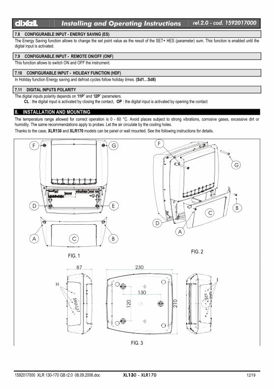
8. INSTALLATION AND MOUNTING
The temperature range allowed for correct operation is 0 - 60 °C. Avoid places subject to strong vibrations, corrosive gases, excessive dirt or humidity. The same recommendations apply to probes. Let the air circulate by the cooling holes.
Thanks to the case, XLR130 and XLR170 models can be panel or wall mounted. See the following instructions for details.
A BC
D E
GF
FIG. 1
A
BC
G
F
D
FIG. 2
87 230
MAX 3
7
210
130
120
MAX
28
HI
FIG. 3
dIXELdIXELdIXELdIXEL Installing and Operating Instructions rel.rel.rel.rel.2222.0 .0 .0 .0 ---- cod. 1592017000 cod. 1592017000 cod. 1592017000 cod. 1592017000
1592017000 XLR 130-170 GB r2.0 08.09.2006.doc XL130 - XLR170 13/19
A
Fig. 6
200
610
0 172
106.44°
19018
Fig. 4
200
192.5
185
6112
60
041114.522.529.5 160.55
167.5175.5179186190
R 58.5
8.5
106.44°
R 5
Fig. 5
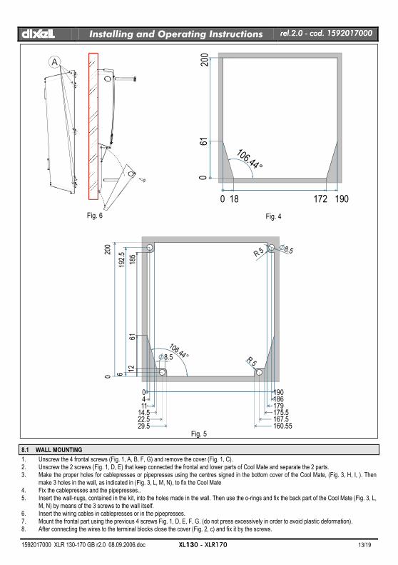
8.1 WALL MOUNTING
1. Unscrew the 4 frontal screws (Fig. 1, A, B, F, G) and remove the cover (Fig. 1, C). 2. Unscrew the 2 screws (Fig. 1, D, E) that keep connected the frontal and lower parts of Cool Mate and separate the 2 parts. 3. Make the proper holes for cablepresses or pipepresses using the centres signed in the bottom cover of the Cool Mate, (Fig. 3, H, I, ). Then
make 3 holes in the wall, as indicated in (Fig. 3, L, M, N), to fix the Cool Mate 4. Fix the cablepresses and the pipepresses.. 5. Insert the wall-nugs, contained in the kit, into the holes made in the wall. Then use the o-rings and fix the back part of the Cool Mate (Fig. 3, L,
M, N) by means of the 3 screws to the wall itself. 6. Insert the wiring cables in cablepresses or in the pipepresses. 7. Mount the frontal part using the previous 4 screws Fig. 1, D, E, F, G. (do not press excessively in order to avoid plastic deformation). 8. After connecting the wires to the terminal blocks close the cover (Fig. 2, c) and fix it by the screws.
dIXELdIXELdIXELdIXEL Installing and Operating Instructions rel.rel.rel.rel.2222.0 .0 .0 .0 ---- cod. 1592017000 cod. 1592017000 cod. 1592017000 cod. 1592017000
1592017000 XLR 130-170 GB r2.0 08.09.2006.doc XL130 - XLR170 14/19
8.2 PANEL MOUNTING
1. Make a hole in the panel with dimensions described in Fig. 4 (simplified) or Fig. 5 (completed) 2. Unscrew the 4 frontal screws (Fig. 1, A, B, F, G) and remove the cover (Fig. 1, C). 3. Unscrew the 2 screws (Fig. 1, D, E) that keep connected the frontal and lower parts of Cool Mate and separate the 2 parts. 4. Cut from the back part of the Cool Mate the teeth indicated in Fig. 6, A. 5. Make the proper holes for cablepresses or pipepresses using the centres signed in the bottom cover of the Cool Mate, (Fig. 3, H, I, ). 6. Fix the cablepresses and the pipepresses.. 7. Insert the wiring cables in cablepresses or in the pipepresses. 8. Join the back and frontal parts, with the panel in the middle, and fix them screwing the 4 screws taken previously away (dimensions 4x35
mm), in the holes of Fig. 1, A, B, D, E. Maximum panel thickness: 6mm. 9. After connecting the wires to the terminal blocks close the cover (Fig. 2, c) and fix it by the screws.
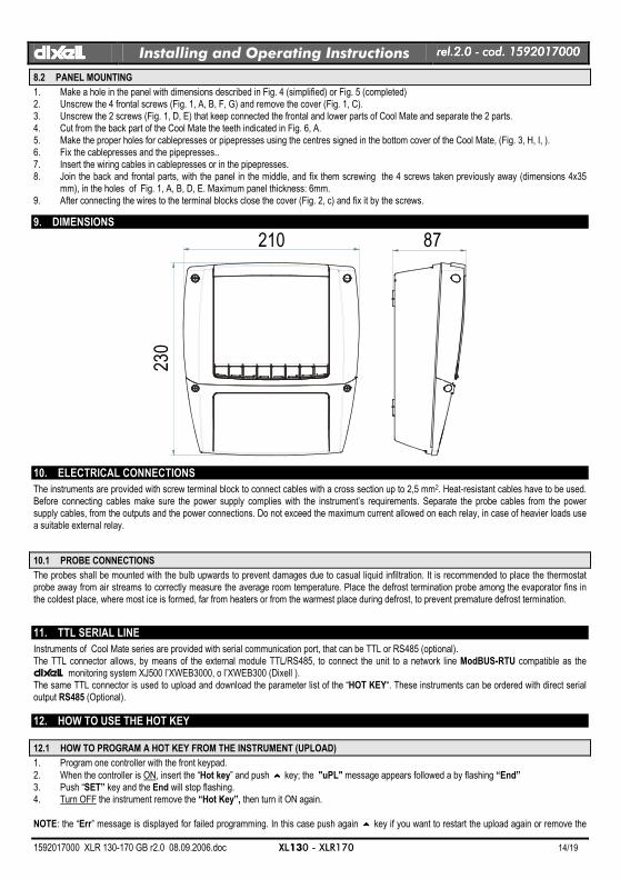
9. DIMENSIONS
210 87
230
10. ELECTRICAL CONNECTIONS
The instruments are provided with screw terminal block to connect cables with a cross section up to 2,5 mm2. Heat-resistant cables have to be used. Before connecting cables make sure the power supply complies with the instrument’s requirements. Separate the probe cables from the power supply cables, from the outputs and the power connections. Do not exceed the maximum current allowed on each relay, in case of heavier loads use a suitable external relay.
10.1 PROBE CONNECTIONS
The probes shall be mounted with the bulb upwards to prevent damages due to casual liquid infiltration. It is recommended to place the thermostat probe away from air streams to correctly measure the average room temperature. Place the defrost termination probe among the evaporator fins in the coldest place, where most ice is formed, far from heaters or from the warmest place during defrost, to prevent premature defrost termination.
11. TTL SERIAL LINE
Instruments of Cool Mate series are provided with serial communication port, that can be TTL or RS485 (optional). The TTL connector allows, by means of the external module TTL/RS485, to connect the unit to a network line ModBUS-RTU compatible as the dIXEL monitoring system XJ500 l’XWEB3000, o l’XWEB300 (Dixell ). The same TTL connector is used to upload and download the parameter list of the “HOT KEY“. These instruments can be ordered with direct serial output RS485 (Optional).
12. HOW TO USE THE HOT KEY
12.1 HOW TO PROGRAM A HOT KEY FROM THE INSTRUMENT (UPLOAD)
1. Program one controller with the front keypad.
2. When the controller is ON, insert the “Hot key” and push oooo key; the "uPL" message appears followed a by flashing “End” 3. Push “SET” key and the End will stop flashing. 4. Turn OFF the instrument remove the “Hot Key”, then turn it ON again.
NOTE: the “Err” message is displayed for failed programming. In this case push again oooo key if you want to restart the upload again or remove the
dIXELdIXELdIXELdIXEL Installing and Operating Instructions rel.rel.rel.rel.2222.0 .0 .0 .0 ---- cod. 1592017000 cod. 1592017000 cod. 1592017000 cod. 1592017000
1592017000 XLR 130-170 GB r2.0 08.09.2006.doc XL130 - XLR170 15/19
“Hot key” to abort the operation.
12.2 HOW TO PROGRAM AN INSTRUMENT USING A HOT KEY (DOWNLOAD)
1. Turn OFF the instrument. 2. Insert a programmed “Hot Key” into the 5 PIN receptacle and then turn the Controller ON. 3. Automatically the parameter list of the “Hot Key” is downloaded into the Controller memory, the “doL” message is blinking followed a by
flashing “End”. 4. After 10 seconds the instrument will restart working with the new parameters. 5. Remove the “Hot Key”.. NOTE the message “Err” is displayed for failed programming. In this case turn the unit off and then on if you want to restart the download again or remove the “Hot key” to abort the operation.
13. ALARM SIGNALS
Message Cause Outputs
“P1” Thermostat probe failure Alarm output ON; Compressor output according to parameters “COn” and “COF”
“P2” Evaporator probe failure Alarm output ON; Other outputs unchanged
“P3” Auxiliary probe failure Alarm output ON; Other outputs unchanged
“HA” Max. temperature alarm Alarm output ON; Other outputs unchanged
“LA” Min. temperature alarm Alarm output ON; Other outputs unchanged
“EE” Data or memory failure Alarm output ON; Other outputs unchanged
“dA” Door switch alarm Alarm output ON; Other outputs unchanged
“EAL” External alarm Alarm output ON; Other outputs unchanged
“BAL” Serious external alarm Alarm output ON; Other outputs OFF
“PAL” Pressure switch alarm Alarm output ON; Other outputs OFF
PAn “Panic” Alarm Alarm output ON; Other outputs unchanged
“rtc” Real time clock alarm Alarm output ON; Other outputs unchanged; Defrosts according to par. “IdF”
The alarm message is displayed until the alarm condition is recovery. All the alarm messages are showed alternating with the room temperature except for the “P1” which is flashing. To reset the “EE” alarm and restart the normal functioning press any key, the “rSt” message is displayed for about 3s.
13.1 SILENCING BUZZER / ALARM RELAY OUTPUT
If “tbA = y”, once the alarm signal is detected the buzzer and the relay are is silenced by pressing any key. If “tbA = n”, only the buzzer is silenced while the alarm relay is on until the alarm condition recovers.
13.2 “EE” ALARM
The dIXEL instruments are provided with an internal check for the data integrity. Alarm “EE” flashes when a failure in the memory data occurs. In such cases the alarm output is enabled.
13.3 ALARM RECOVERY
Probe alarms : “P1” (probe1 faulty), “P2” and “P3”; they automatically stop 10s after the probe restarts normal operation. Check connections before replacing the probe. Temperature alarms “HA” and “LA” automatically stop as soon as the thermostat temperature returns to normal values or when the defrost starts. Door switch alarm “dA” stop as soon as the door is closed. External alarms “EAL”, “BAL” stop as soon as the external digital input is disabled “PAL” alarm is recovered by switching OFF the instrument.
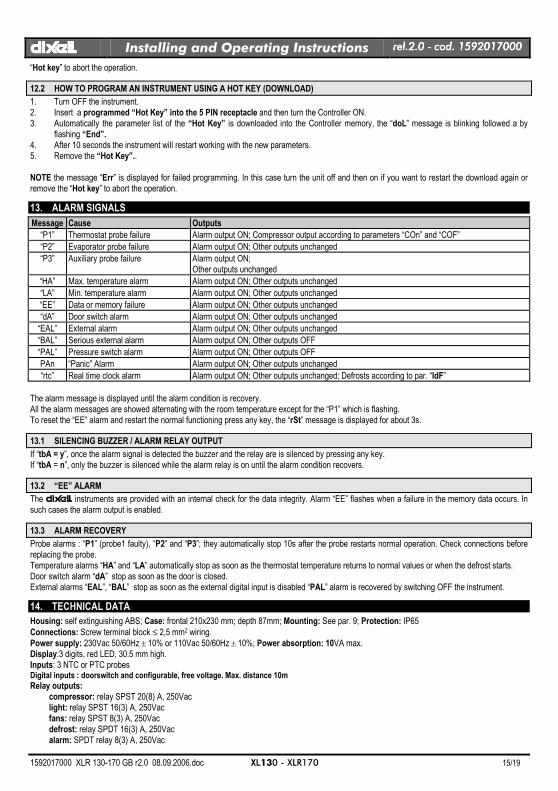
14. TECHNICAL DATA
Housing: self extinguishing ABS; Case: frontal 210x230 mm; depth 87mm; Mounting: See par. 9; Protection: IP65
Connections: Screw terminal block ≤ 2,5 mm2 wiring.
Power supply: 230Vac 50/60Hz ± 10% or 110Vac 50/60Hz ± 10%; Power absorption: 10VA max. Display:3 digits, red LED, 30.5 mm high. Inputs: 3 NTC or PTC probes Digital inputs : doorswitch and configurable, free voltage. Max. distance 10m
Relay outputs: compressor: relay SPST 20(8) A, 250Vac light: relay SPST 16(3) A, 250Vac fans: relay SPST 8(3) A, 250Vac defrost: relay SPDT 16(3) A, 250Vac alarm: SPDT relay 8(3) A, 250Vac
dIXELdIXELdIXELdIXEL Installing and Operating Instructions rel.rel.rel.rel.2222.0 .0 .0 .0 ---- cod. 1592017000 cod. 1592017000 cod. 1592017000 cod. 1592017000
1592017000 XLR 130-170 GB r2.0 08.09.2006.doc XL130 - XLR170 16/19
auxiliary: SPST relay 20(8) A, 250Vac Other output : Alarm buzzer (Standard) Direct RS485 (optional) Serial output : TTL standard Communication protocol: Modbus - RTU Data storing: on the non-volatile memory (EEPROM). Internal clock back-up: 24 hours Kind of action: 1B; Pollution grade: normal; Software class: A. Operating temperature: 0÷60 °C. Storage temperature: -25÷60 °C. Relative humidity: 20÷85% (no condensing) Measuring and regulation range: NTC probe: -40÷110°C (-58÷230°F) Resolution: 0,1 °C or 1°C or 1 °F (selectable). Accuracy (ambient temp. 25°C): ±0,5 °C ±1 digit
15. CONNECTIONS
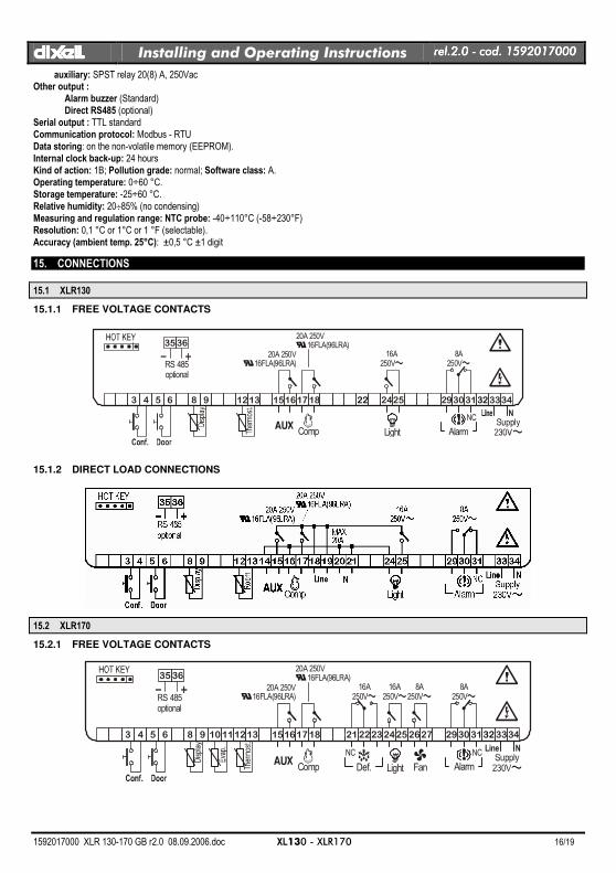
15.1 XLR130
15.1.1 FREE VOLTAGE CONTACTS
1 2 3 4 5 6 7 8 9 10111213141516171819202122232425262728293031323334
Light
16A250V~
20A 250V16FLA(96LRA)
20A 250V16FLA(96LRA)
8A250V~
N
Alarm
NC
3536
RS 485optional
Comp
15.1.2 DIRECT LOAD CONNECTIONS
15.2 XLR170
15.2.1 FREE VOLTAGE CONTACTS
1 2 3 4 5 6 7 8 9 10111213141516171819202122232425262728293031323334
Light
16A250V~
16A250V~
8A250V~
20A 250V16FLA(96LRA)
20A 250V16FLA(96LRA)
8A250V~
N
Comp
Line
Def.
NC
Alarm
NC
Fan
3536
RS 485optional
dIXELdIXELdIXELdIXEL Installing and Operating Instructions rel.rel.rel.rel.2222.0 .0 .0 .0 ---- cod. 1592017000 cod. 1592017000 cod. 1592017000 cod. 1592017000
1592017000 XLR 130-170 GB r2.0 08.09.2006.doc XL130 - XLR170 17/19
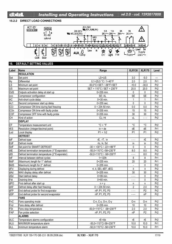
15.2.2 DIRECT LOAD CONNECTIONS
16. DEFAULT SETTING VALUES
Label Name Range XLR130 XLR170 Level
REGULATION
Set Set point LS÷US 3.0 -5.0 ---
Hy Differential 0,1÷25,5 °C / 1÷45°F 2.0 2.0 Pr1
LS Minimum set point -50,0°C÷SET / -58°F÷SET -10.0 -30,0 Pr2
US Maximum set point SET ÷ 110°C / SET ÷ 230°F 20.0 20.0 Pr2
OdS Outputs activation delay at start up 0÷255 min. 0 0 Pr2
cco Compressor configuration SE; AL SE SE Pr2
AC Anti-short cycle delay 0÷30 min. 1 1 Pr1
Ac1 Second compressor start up delay 0÷255 sec. 0 0 Pr2
CCt Compressor ON time during fast freezing 0 ÷ 23h 50 min. 0.0 0.0 Pr2
COn Compressor ON time with faulty probe 0÷255 min. 15 15 Pr2
COF Compressor OFF time with faulty probe 0÷255 min. 30 30 Pr2
CH Kind of action CL; Ht cL - - - Pr2
DISPLAY
CF Temperature measurement unit °C ÷ °F °C °C Pr2
rES Resolution (integer/decimal point) in ÷ de dE dE Pr1
Lod Local display P1 ÷ 1r2 P1 P1 Pr2
DEFROST
tdF Defrost type rE, rT, in - - - rE Pr2
EdF Defrost mode rtc, In, Sd in in Pr2
SdF Set point for SMART DEFROST -30 ÷ +30°C / -22÷+86°F 0 0 Pr2
dtE Defrost termination temperature (1°Evaporator) -50,0÷110°C /-58÷230°F 8.0 8.0 Pr2
dtS Defrost termination temperature (2°Evaporator) -50,0÷110°C / -58÷230°F - - - 8.0 Pr2
IdF Interval between defrost cycles 1÷120h 8 8 Pr1
MdF (Maximum) length for 1° defrost 0÷255 min. 20 20 Pr1
MdS Maximum) length for 2° defrost. 0÷255 min. - 0 Pr2
dFd Displaying during defrost rt, it, SEt, dEF, dEG it it Pr2
dAd MAX display delay after defrost 0÷255 min. 30 30 Pr2
dSd Start defrost delay 0÷99 min. - - - 0 Pr2
Fdt Draining time 0÷60 min. - - - 0 Pr2
dPO First defrost after start up n ÷ y n n Pr2
dAF Defrost delay after fast freezing 0 ÷ 23h 50 min. 2 2.0 Pr2
dFP End defrost probe for first evaporator nP; P1, P2, P3 - - - P2 Pr2
dSP End defrost probe for second evaporator nP; P1, P2, P3 - - - nP Pr2
FANS
FnC Fans operating mode C-n, C-y, O-n, O-y O-n O-n Pr2
Fnd Fans delay after defrost 0÷255 min. 10 10 Pr2
FSt Fans stop temperature -50,0÷110°C / -58÷230°F 2.0 2.0 Pr2
FAP Fan probe selection nP; P1, P2, P3 nP P2 Pr2
ALARMS
ALC Temperature alarms configuration rE÷Ab rE rE Pr2
ALU MAXIMUM temperature alarm -50,0÷110°C/-58÷230°F 10.0 10.0 Pr1
ALL minimum temperature alarm -50,0÷110°C/ -58÷230°F 10.0 10.0 Pr1
dIXELdIXELdIXELdIXEL Installing and Operating Instructions rel.rel.rel.rel.2222.0 .0 .0 .0 ---- cod. 1592017000 cod. 1592017000 cod. 1592017000 cod. 1592017000
1592017000 XLR 130-170 GB r2.0 08.09.2006.doc XL130 - XLR170 18/19
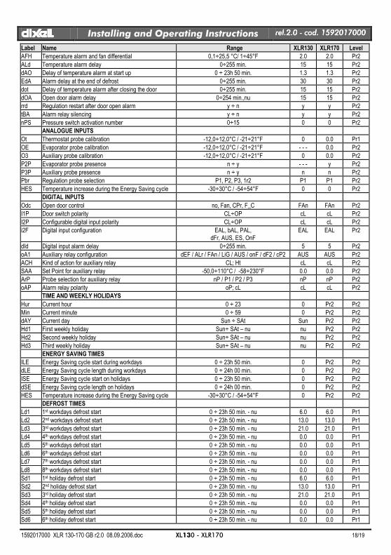
Label Name Range XLR130 XLR170 Level
AFH Temperature alarm and fan differential 0,1÷25,5 °C/ 1÷45°F 2.0 2.0 Pr2
ALd Temperature alarm delay 0÷255 min. 15 15 Pr2
dAO Delay of temperature alarm at start up 0 ÷ 23h 50 min. 1.3 1.3 Pr2
EdA Alarm delay at the end of defrost 0÷255 min. 30 30 Pr2
dot Delay of temperature alarm after closing the door 0÷255 min. 15 15 Pr2
dOA Open door alarm delay 0÷254 min.,nu 15 15 Pr2
rrd Regulation restart after door open alarm y ÷ n y y Pr2
tBA Alarm relay silencing y ÷ n y y Pr2
nPS Pressure switch activation number 0÷15 0 0 Pr2
ANALOGUE INPUTS
Ot Thermostat probe calibration -12,0÷12,0°C / -21÷21°F 0 0.0 Pr1
OE Evaporator probe calibration -12,0÷12,0°C / -21÷21°F - - - 0.0 Pr2
O3 Auxiliary probe calibration -12,0÷12,0°C / -21÷21°F 0 0.0 Pr2
P2P Evaporator probe presence n ÷ y - - - y Pr2
P3P Auxiliary probe presence n ÷ y n n Pr2
Pbr Regulation probe selection P1, P2, P3, 1r2 P1 P1 Pr2
HES Temperature increase during the Energy Saving cycle -30÷30°C / -54÷54°F 0 0 Pr2
DIGITAL INPUTS
Odc Open door control no, Fan, CPr, F_C FAn FAn Pr2
I1P Door switch polarity CL÷OP cL cL Pr2
I2P Configurable digital input polarity CL÷OP cL cL Pr2
i2F Digital input configuration EAL, bAL, PAL, dFr, AUS, ES, OnF
EAL EAL Pr2
dId Digital input alarm delay 0÷255 min. 5 5 Pr2
oA1 Auxiliary relay configuration dEF / ALr / FAn / LiG / AUS / onF / dF2 / cP2 AUS AUS Pr2
ACH Kind of action for auxiliary relay CL; Ht cL cL Pr2
SAA Set Point for auxiliary relay -50,0÷110°C / -58÷230°F 0.0 0.0 Pr2
ArP Probe selection for auxiliary relay nP / P1 / P2 / P3 nP nP Pr2
oAP Alarm relay polarity oP; cL cL cL Pr2
TIME AND WEEKLY HOLIDAYS
Hur Current hour 0 ÷ 23 0 Pr2 Pr2
Min Current minute 0 ÷ 59 0 Pr2 Pr2
dAY Current day Sun ÷ SAt Sun Pr2 Pr2
Hd1 First weekly holiday Sun÷ SAt – nu nu Pr2 Pr2
Hd2 Second weekly holiday Sun÷ SAt – nu nu Pr2 Pr2
Hd3 Third weekly holiday Sun÷ SAt – nu nu Pr2 Pr2
ENERGY SAVING TIMES
ILE Energy Saving cycle start during workdays 0 ÷ 23h 50 min. 0 Pr2 Pr2
dLE Energy Saving cycle length during workdays 0 ÷ 24h 00 min. 0 Pr2 Pr2
ISE Energy Saving cycle start on holidays 0 ÷ 23h 50 min. 0 Pr2 Pr2
dSE Energy Saving cycle length on holidays 0 ÷ 24h 00 min. 0 Pr2 Pr2
HES Temperature increase during the Energy Saving cycle -30÷30°C / -54÷54°F 0 Pr2 Pr2
DEFROST TIMES
Ld1 1st workdays defrost start 0 ÷ 23h 50 min. - nu 6.0 6.0 Pr1
Ld2 2nd workdays defrost start 0 ÷ 23h 50 min. - nu 13.0 13.0 Pr1
Ld3 3rd workdays defrost start 0 ÷ 23h 50 min. - nu 21.0 21.0 Pr1
Ld4 4th workdays defrost start 0 ÷ 23h 50 min. - nu 0.0 0.0 Pr1
Ld5 5th workdays defrost start 0 ÷ 23h 50 min. - nu 0.0 0.0 Pr1
Ld6 6th workdays defrost start 0 ÷ 23h 50 min. - nu 0.0 0.0 Pr1
Ld7 7th workdays defrost start 0 ÷ 23h 50 min. - nu 0.0 0.0 Pr1
Ld8 8th workdays defrost start 0 ÷ 23h 50 min. - nu 0.0 0.0 Pr1
Sd1 1st holiday defrost start 0 ÷ 23h 50 min. - nu 6.0 6.0 Pr1
Sd2 2nd holiday defrost start 0 ÷ 23h 50 min. - nu 13.0 13.0 Pr1
Sd3 3rd holiday defrost start 0 ÷ 23h 50 min. - nu 21.0 21.0 Pr1
Sd4 4th holiday defrost start 0 ÷ 23h 50 min. - nu 0.0 0.0 Pr1
Sd5 5th holiday defrost start 0 ÷ 23h 50 min. - nu 0.0 0.0 Pr1
Sd6 6th holiday defrost start 0 ÷ 23h 50 min. - nu 0.0 0.0 Pr1
dIXELdIXELdIXELdIXEL Installing and Operating Instructions rel.rel.rel.rel.2222.0 .0 .0 .0 ---- cod. 1592017000 cod. 1592017000 cod. 1592017000 cod. 1592017000
1592017000 XLR 130-170 GB r2.0 08.09.2006.doc XL130 - XLR170 19/19
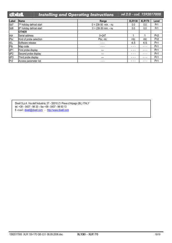
Label Name Range XLR130 XLR170 Level
Sd7 7th holiday defrost start 0 ÷ 23h 50 min. - nu 0.0 0.0 Pr1
Sd8 8th holiday defrost start 0 ÷ 23h 50 min. - nu 0.0 0.0 Pr1
OTHER
Adr Serial address 0÷247 1 1 Pr2
Pbc Kind of probe selection Pbc, ntc ntc ntc Pr2
rEL Software release - - - 4.5 4.5 Pr1
Ptb Map code - - - - - - - - - Pr1
dP1 First probe display --- - - - - - - Pr1
dP2 Second probe display --- - - - - - - Pr1
dP3 Third probe display --- - - - - - - Pr1
Pr2 Access parameter list - - - - - - - - - Pr1
Dixell S.p.A. Via dell’Industria, 27 - 32010 Z.I Pieve d’Alpago (BL) ITALY tel. +39 – 0437 - 98 33 – fax +39 - 0437 - 98 93 13 E-mail: [email protected] - http://www.dixell.com