Embed Size (px)
Citation preview
arX
iv:a
cc-p
hys/
9607
003
v1
15 J
ul 1
996
A Scintillating Fiber Hodoscope for a Bremstrahlung Luminosity Monitor at an
Electron−Positron Collider
D.H. Brown, D.H. Orlov, G.S. Varner∗, W.A. WorstellPhysics Department, Boston University, 590 Commonwealth Avenue, Boston, MA 02215
S.I. Redin†
Budker Institute of Nuclear Physics, Novosibirsk 630090 Russia
(January 14, 2003)
The performance of a scintillating fiber (2mm diameter) position sensitive detector (4.8×4.8 cm2
active area) for the single bremstrahlung luminosity monitor at the VEPP-2M electron-positroncollider in Novosibirsk, Russia is described. Custom electronics is triggered by coincident hits inthe X and Y planes of 24 fibers each, and reduces 64 PMT signals to a 10 bit (X,Y) address.Hits are accumulated (10 kHz) in memory and display (few Hz) the VEPP-2M collision vertex.Fitting the strongly peaked distribution ( ∼ 3-4 mm at 1.6m from the collision vertex of VEPP-2M) to the expected QED angular distribution yields a background in agreement with an independentdetermination of the VEPP-2M luminosity.
I. INTRODUCTION
The VEPP-2M e+e− collider at the Budker Instituteof Nuclear Physics, Novosibirsk, Russia is currently en-gaged in high precision measurements of hadron produc-tion in the 1 GeV region. These measurements are usefulfor reduction of the uncertainties on hadronic vacuumpolarization contributions (arising from virtual photoninteractions with the vector mesons ρ, ω and φ) to sev-eral fundamental constants of physics. Among these con-stants are, the muon g−2 value [1], the running fine struc-ture constant evaluated at the Z-boson mass, α(M2
Z) [2][3], and the hyperfine structure of muonium [4]. Thedetectors CMD2 [5] and SND [6] are currently takingdata in VEPP-2M to understand their systematic errorsand to make preliminary measurements for these physicsgoals and to contribute to the planning of future high-luminosity φ-factories [7] [8].
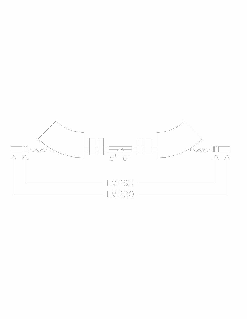
In the CMD2 experiment, precise luminosity deter-mination is performed offline by analysis of large angleBhabha scattering events. Online luminosity determina-tion with less accuracy is performed by small angle singleand double bremstrahlung monitors. These are placedoutside of CMD2 along tangents to the VEPP-2M col-liding beam ring as shown in Fig. 1. The fundamentalprocesses which generate photons from the VEPP-2Mcollision vertex are in descending order of cross section:single and double bremstrahlung, and two photon anni-hilation [9].
The CMD2 luminosity monitor (LM) systems consist
of 70 × 70 × 100 mm3 BGO crystal scintillators and areused as rate counters [10]. The single bremstrahlung sig-nal is difficult to distinguish from background due tobeam-residual gas nuclei bremstrahlung (which sharesthe same strongly forward peaked QED angular distribu-tion as the beam-beam single bremstrahlung signal) andlost beam interactions in the vacuum chamber. The lat-ter generates photons and charged particles with a rela-tively broader angular distribution depending on VEPP-2M machine conditions.
The double bremstrahlung signal can be obtained by amethod of coincidence between signals from LM systemson either side of CMD2. The simple coincidence sig-nal (N1) of the two LM systems contains actual doublebremstrahlung (γγ) events plus accidental (acc) coinci-dences from the (orders of magnitude larger rate) singlebremstrahlung events: N1 = Nγγ +Nacc. The accidentalcoincidence rate can be measured by the coincidence sig-nal (N2 = Nacc) between one LM signal delayed by a fewVEPP-2M beam crossings from the undelayed signal inwhich double bremstrahlung events cannot possibly oc-cur. The accidental background can then be removed bysubtraction of the two which isolates the double brem-strahlung events:
Nγγ = N1 − N2
= (Nγγ + Nacc) − Nacc
The problem with this method is that the small doublebremstrahlung cross section implies a small number ofevents which means a large statistical error. This leads
∗currently at Physics Department, University of Hawaii†currently at Physics Department, Yale University
1
in practise to occasional negative total counts for doublebremstrahlung.
In response to the failure of rate-dependent techniquesto distinguish between luminosity monitoring processesand backgrounds, the possibility to identify a signal pro-cess by its characteristic angular distribution can then beexploited. For this purpose a small diameter scintillatingfiber hodoscope is employed as a luminosity monitor po-sition sensitive detector (LMPSD) for the incidence faceof the LMBGO to measure the sharply peaked profileof the photon distribution. The deviation from the ex-pected QED angular distribution is used to measure thebackground to be subtracted from the total LMBGO sig-nal. In addition, the LMPSD information provides realtime visual feedback for accelerator control of the posi-tion and stability over time of the VEPP-2M collidingbeam vertex (see Fig. 4).
The organization of this note is as follows. Sec. IIoutlines the main LMPSD components. Sec. III de-scribes the uniformity measurements taken with a ra-dioactive source and the performance of the LMPSD dur-ing colliding-beams operation of VEPP-2M.
II. LMPSD COMPONENTS
The LMPSD consists of a scintillating fiber packagemounted to a PMT-base assembly with custom designedreadout electronics. The fiber package, PMT-base as-sembly and readout electronics are discussed below.
A. Scintillating Fiber Package
Two scintillating fiber planes each have 24 fibers andare oriented in transverse directions to the incident pho-tons from the interaction region of VEPP-2M. The ac-tive part of the fiber planes are 2mm diameter roundradiation-hard Bicron scintillator each 6cm in length.They are index-of-refraction matched by Bicron BC-600epoxy to 25cm long 2mm round non-scintillating claddedpolystyrene fibers. An aluminum frame has been con-structed to fix the fibers without introducing materialbefore or after the fiber planes in the incidence window.
Both ends of the fibers were polished. The fiber ends inthe aluminum frame are held in place by clamps and ad-hesive to a mirrored surface, which enhances by 60 % theun-mirrored fiber light yield. The PMT-end of the fibersare held in place by a grid of 64 guide holes machined ina lucite plate. Cross talk was minimized by moving theplate within the tolerance of the bolt holes and measur-ing signals in a 3x3 grid of pixels with a UV-excited testfiber in the central pixel. This guide-plate is pinned tothe PMT mounting plate. The entire fiber/PMT packageis shown schematically in Fig. 2.
B. PMT Base Assembly
The photomultiplier (PMT) used is a Philips XP4722segmented output electrode device with 64 individual 10stage electron-multiplication channels. The PMT baseassembly was custom designed and built in a circular ar-ray which allows each channel to be amplified separatelyby a current feedback operational amplifier PMI OP-160.All channels were mounted on a radial spoke (32 per side)of the circular printed circuit board. The channels on oneside were rotated relative to the channels on the other tominimize cross talk through the pc board.
After initial testing the PMT gains were equalized bymodifiying the op-amp feedback resistors. Two raisedcommon voltage rings supply the op-amps.
C. Mechanical Support
The fiber package is supported by attachments to thePMT mounting plate. This plate is insulating since thePhilips XP4722 is used with the exterior metal ring athigh voltage to maximize the PMT gain. A clear lucitefiber guide plate (with an 8x8 grid of fiber feedthroughholes) is fixed to the black plastic PMT mounting plate.The non-scintillating part of the fibers are bent equallyfrom the two perpendicular planes in the fiber packageto the PMT.
The other side of the PMT plate has a groove which ac-comodates the rim of a tapering (5” - 2”) mu-metal shieldwhich provides a light tight enclosure for the PMT baseassembly. The cables are run out the narrow end of themu-metal shield which is suitably taped closed for lighttightness.
The amplified signal from each channel is conducted2 meters through individual RG-174 coaxial cable to the“CODER” readout electronics. The CODER is locatedin a special NIM crate mounted under the CMD2 detec-tor which converts the 64 signals to a 10 bit address forthe LMPSD hit (5 bits for X, 5 bits for Y). The 10 bitaddress is then sent by a 4 meter 40 pin ribbon cable toa CAMAC crate.
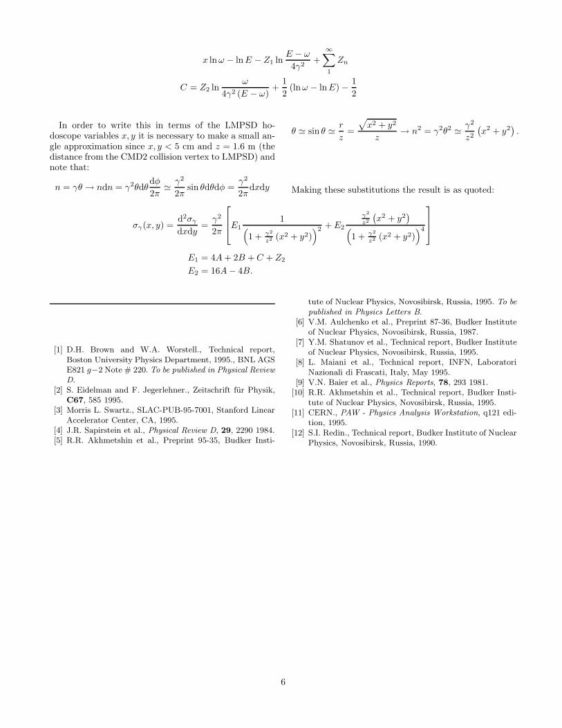
D. The CODER Readout Electronics
The CODER electronics consists of commercial dis-criminators, three custom NIM modules and a customCAMAC unit and is shown in Fig. 3. The first NIMmodule delivers two 5-bit values, by means of 32-bit pri-ority encoders, for the HI and LO fibers excited in agiven plane. A second such module produces HI-LO val-ues for the other fiber plane. If HI−LO=0 then only asingle fiber was hit. If HI−LO>0 then there were mul-tiple fibers hit in the plane. (In VEPP-2M, the rate formultiple hits turned out to be quite small.) The HI-LO
2
modules also issue pulses useful for determining the tim-ing of the hit.
The third NIM module is the CODER properwhich delivers the HI−LO=DIFF difference and the(HI+LO)/2=MEAN center of the hit by means of a 2kPROM. A dip switch defining N allows the selection ofevents with DIFF<N. The signals are transformed to dif-ferential TTL to ensure that signal degradation to theCAMAC crate will not destroy LMPSD information. TheCAMAC unit transforms the signals back to ground rela-tive TTL and defines the valid event condition describedbelow.
The CODER data output consists of two 16-bit words,one for X and the other for the Y plane. Each word isissued in parallel upon a valid event defined by the log-ical AND between three signals: X plane OR, Y planeOR, and computer-not-busy. This signal defines the CA-MAC LAM. The least significant four bits (of the 16-bitdata word for each fiber plane) are the DIFF, the nextmore significant five bits are the MEAN taken as thephoton position, while the most significant two label thedata word as X or Y. The computer program sends theDIFF and MEAN bits (along with the VEPP-2M beamcurrent updated every 100th event) to a disk residentfile in a form suitable for analysis software [11]. Thelogical AND signal of the X and Y plane ORs (withoutcomputer-busy veto) was additionally readout and sentto a CAMAC scaler.
III. LMPSD PERFORMANCE
A. Calibration
Before mounting the LMPSD in VEPP-2M, LMPSDsignal responses to illumination by a Ru106 source weremeasured to determine (and equalize) the uniformityamong fiber channel responses throughout the data ac-quisition chain.
The 64-channel PMT-base assembly has gain varia-tions of at least a factor of 2 while there are also 25%variations in individual fiber light yields. The discrimi-nator thresholds in the CODER of the fiber-PMT signalsprovide a convenient means for equalizing the channel re-sponses to constant illumination. Constant illuminationis achieved with an uncollimated Ru106 source of 3.5 MeVelectrons placed 15 cm away from the X and Y planes ofthe LMPSD.
There are 4 discriminator thresholds for the 48 chan-nels (24 for both X and Y) in the LMPSD. After check-ing the signal response to the collimated Ru106 sourcefor each channel on an oscilloscope the channels weregrouped into 4 threshold groups. The LMPSD was sub-jected to uncollimated constant illumination and thethresholds were adjusted to improve the uniformity ofresponse across the channels. In some cases, high gainPMT channels were re-matched with low light yielding
fibers to create a more uniform response. The uniformityappears to be quite stable over long periods of operationand after complete reinstallation procedures (from oneside of CMD2 to the other).
The channels tuned in this manner have yielded thephoton beam position in the data presented below andappear to be acceptable. The limitation to the uniformityis determined mainly by the lack of individual channeldiscrimination. If this were built into the pc-board or ifmore discriminators were available the uniformity of thedevice could be improved.
B. Conversion of Photons
As depicted by small wedges on the outer radii of thebending magnets in Fig. 1, the vacuum chamber of theVEPP-2M storage ring has special photon channels witha thin (∼ 1 mm) stainless steel window (∼ 2 × 4 cm2)through which the bremstrahlung photons may pass. Inprinciple, single bremstrahlung photons will convert toan e+e− pair through this chamber wall. However, ear-lier measurements using wire chambers determined thatbeam loss interactions in the vacuum chamber and otherhardware in the VEPP-2M ring cause a much largercharged particle background at the luminosity monitorsthan the photon-e+e− conversion signal.
Therefore, a scintillator/PMT assembly was placedjust in front of the LMPSD to veto charged particles.This was implemented in the electronics by taking both ofthe discriminator outputs from the scintillator signal andfeeding them into channel 30 and 32 in the HI-LO NIMmodules. With DIFF<1 event definition, this meant thata scintillator hit in those channels and a fiber hit in chan-nels 1-24 would certainly yield DIFF>1 and hence theevent would not be issued as valid.
With photon conversions in the vacuum chamber win-dow and any other charged particle background mostlyremoved by a scintillator veto, photon purity of the signalreaching the LMPSD was significantly increased. To in-troduce post-scintillator conversion and thereby increasethe efficiency of the LMPSD several different thicknessesof tungsten plates (varying from 1 mm to 3.5 cm) weretested. In addition, the light tight enclosure built aroundthe fiber package introduces a further 1 mm of stainlesssteel. After comparison of the peak value and width ofthe two dimensional distributions for all configurations(the largest peak results in the narrowest width becauseof the self-trigger of LMPSD) the optimal configurationwas observed to be an additional 1 mm stainless steelplate placed in front of the LMPSD enclosure.
C. Colliding Beam Data
The LMPSD is intended to provide position informa-tion useful for determining the angular distribution of
3
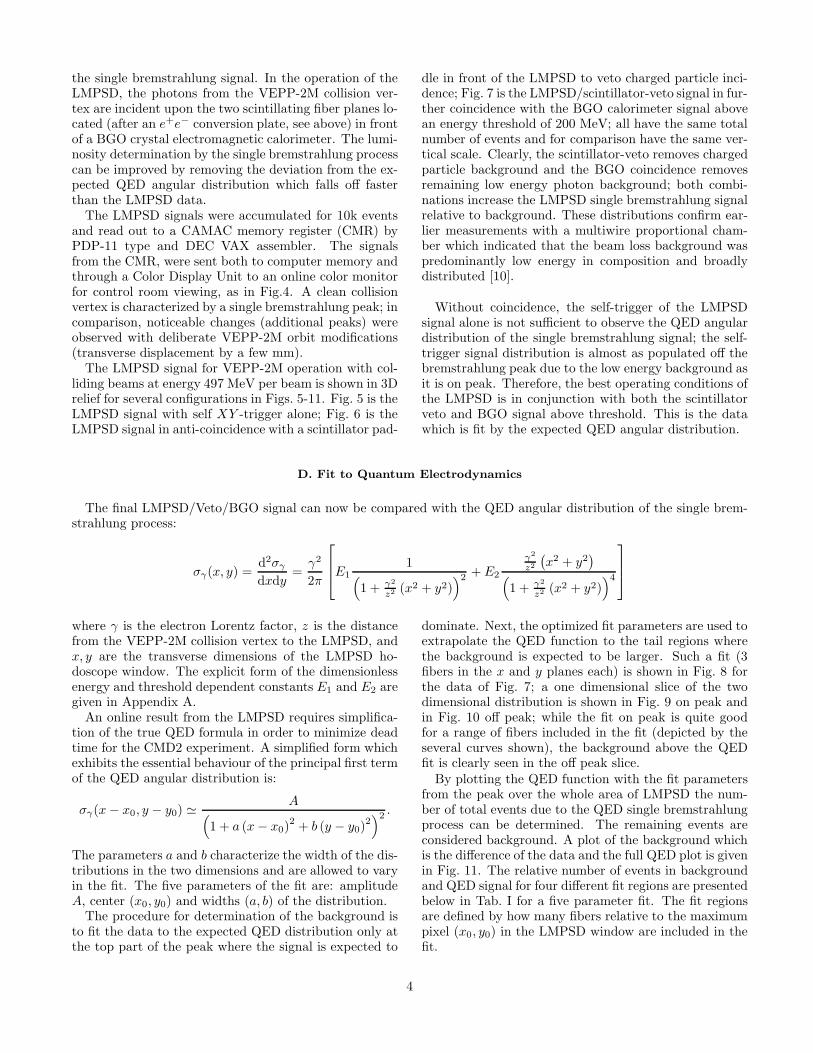
the single bremstrahlung signal. In the operation of theLMPSD, the photons from the VEPP-2M collision ver-tex are incident upon the two scintillating fiber planes lo-cated (after an e+e− conversion plate, see above) in frontof a BGO crystal electromagnetic calorimeter. The lumi-nosity determination by the single bremstrahlung processcan be improved by removing the deviation from the ex-pected QED angular distribution which falls off fasterthan the LMPSD data.
The LMPSD signals were accumulated for 10k eventsand read out to a CAMAC memory register (CMR) byPDP-11 type and DEC VAX assembler. The signalsfrom the CMR, were sent both to computer memory andthrough a Color Display Unit to an online color monitorfor control room viewing, as in Fig.4. A clean collisionvertex is characterized by a single bremstrahlung peak; incomparison, noticeable changes (additional peaks) wereobserved with deliberate VEPP-2M orbit modifications(transverse displacement by a few mm).
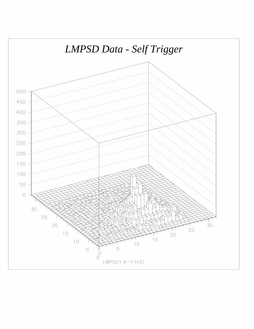
The LMPSD signal for VEPP-2M operation with col-liding beams at energy 497 MeV per beam is shown in 3Drelief for several configurations in Figs. 5-11. Fig. 5 is theLMPSD signal with self XY -trigger alone; Fig. 6 is theLMPSD signal in anti-coincidence with a scintillator pad-
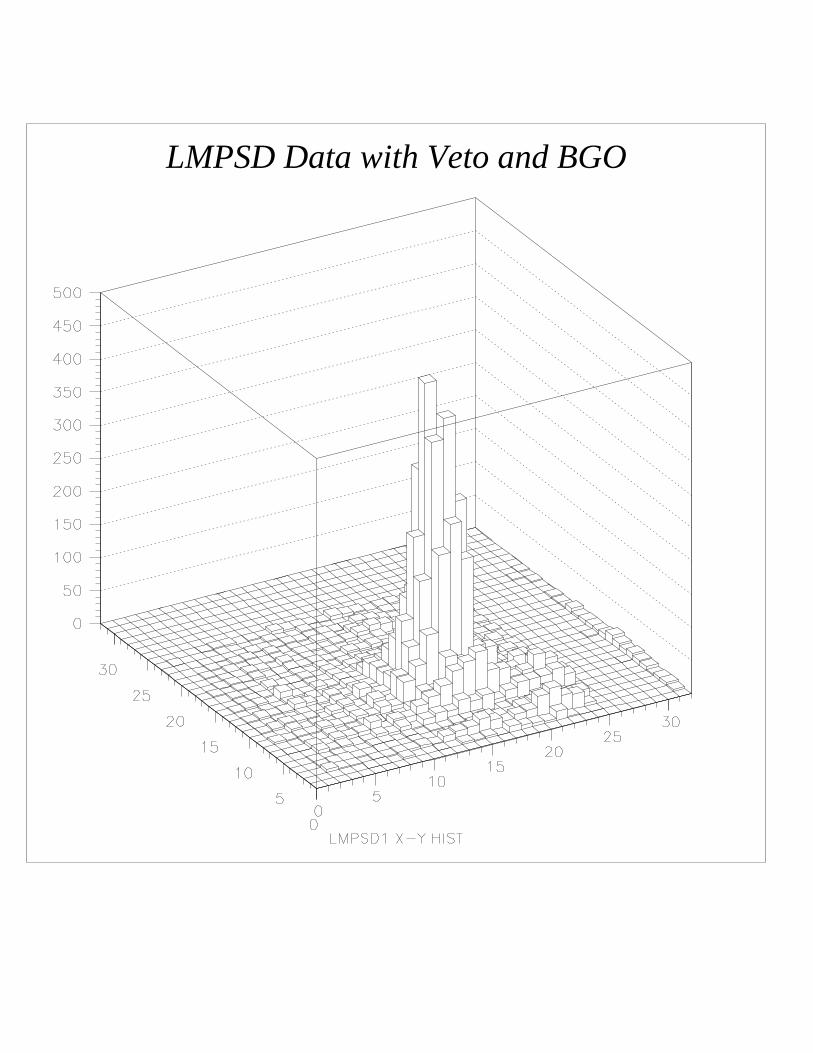
dle in front of the LMPSD to veto charged particle inci-dence; Fig. 7 is the LMPSD/scintillator-veto signal in fur-ther coincidence with the BGO calorimeter signal abovean energy threshold of 200 MeV; all have the same totalnumber of events and for comparison have the same ver-tical scale. Clearly, the scintillator-veto removes chargedparticle background and the BGO coincidence removesremaining low energy photon background; both combi-nations increase the LMPSD single bremstrahlung signalrelative to background. These distributions confirm ear-lier measurements with a multiwire proportional cham-ber which indicated that the beam loss background waspredominantly low energy in composition and broadlydistributed [10].
Without coincidence, the self-trigger of the LMPSDsignal alone is not sufficient to observe the QED angulardistribution of the single bremstrahlung signal; the self-trigger signal distribution is almost as populated off thebremstrahlung peak due to the low energy background asit is on peak. Therefore, the best operating conditions ofthe LMPSD is in conjunction with both the scintillatorveto and BGO signal above threshold. This is the datawhich is fit by the expected QED angular distribution.
D. Fit to Quantum Electrodynamics
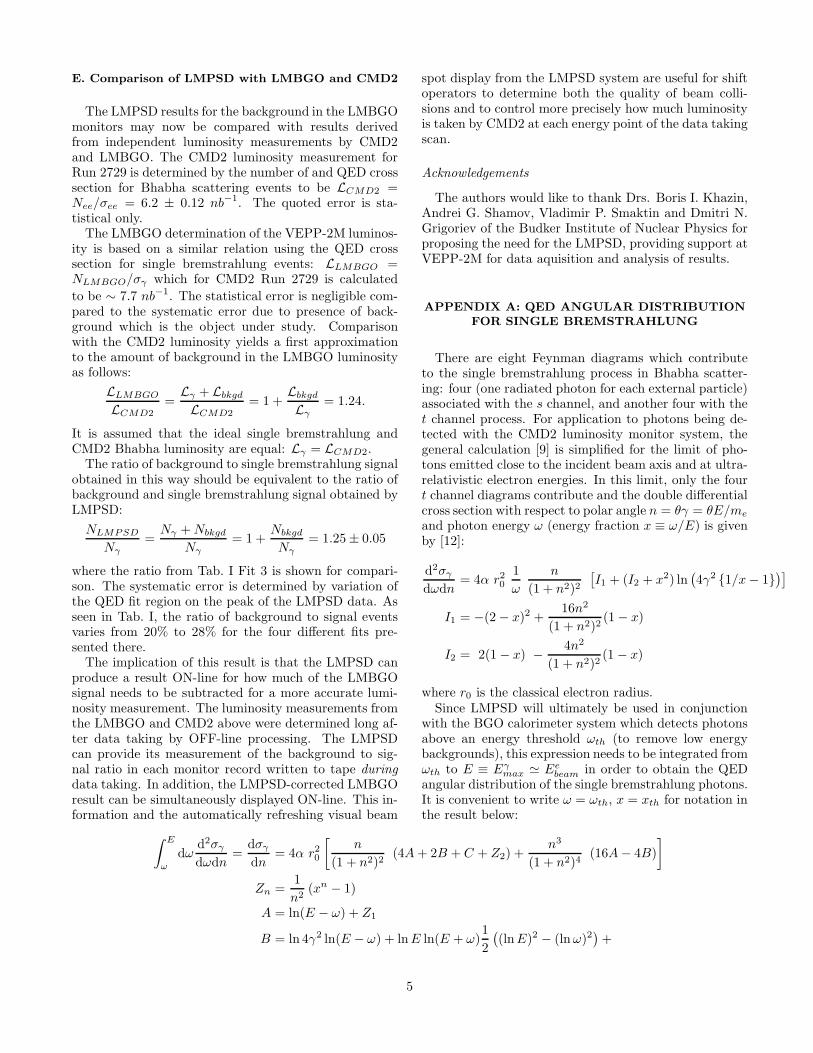
The final LMPSD/Veto/BGO signal can now be compared with the QED angular distribution of the single brem-strahlung process:
σγ(x, y) =d2σγ
dxdy=
γ2
2π
E1
1(
1 + γ2
z2 (x2 + y2))2
+ E2
γ2
z2
(
x2 + y2)
(
1 + γ2
z2 (x2 + y2))4
where γ is the electron Lorentz factor, z is the distancefrom the VEPP-2M collision vertex to the LMPSD, andx, y are the transverse dimensions of the LMPSD ho-doscope window. The explicit form of the dimensionlessenergy and threshold dependent constants E1 and E2 aregiven in Appendix A.
An online result from the LMPSD requires simplifica-tion of the true QED formula in order to minimize deadtime for the CMD2 experiment. A simplified form whichexhibits the essential behaviour of the principal first termof the QED angular distribution is:
σγ(x − x0, y − y0) 'A
(
1 + a (x − x0)2 + b (y − y0)
2)2
.
The parameters a and b characterize the width of the dis-tributions in the two dimensions and are allowed to varyin the fit. The five parameters of the fit are: amplitudeA, center (x0, y0) and widths (a, b) of the distribution.
The procedure for determination of the background isto fit the data to the expected QED distribution only atthe top part of the peak where the signal is expected to
dominate. Next, the optimized fit parameters are used toextrapolate the QED function to the tail regions wherethe background is expected to be larger. Such a fit (3fibers in the x and y planes each) is shown in Fig. 8 forthe data of Fig. 7; a one dimensional slice of the twodimensional distribution is shown in Fig. 9 on peak andin Fig. 10 off peak; while the fit on peak is quite goodfor a range of fibers included in the fit (depicted by theseveral curves shown), the background above the QEDfit is clearly seen in the off peak slice.
By plotting the QED function with the fit parametersfrom the peak over the whole area of LMPSD the num-ber of total events due to the QED single bremstrahlungprocess can be determined. The remaining events areconsidered background. A plot of the background whichis the difference of the data and the full QED plot is givenin Fig. 11. The relative number of events in backgroundand QED signal for four different fit regions are presentedbelow in Tab. I for a five parameter fit. The fit regionsare defined by how many fibers relative to the maximumpixel (x0, y0) in the LMPSD window are included in thefit.
4
E. Comparison of LMPSD with LMBGO and CMD2
The LMPSD results for the background in the LMBGOmonitors may now be compared with results derivedfrom independent luminosity measurements by CMD2and LMBGO. The CMD2 luminosity measurement forRun 2729 is determined by the number of and QED crosssection for Bhabha scattering events to be LCMD2 =Nee/σee = 6.2 ± 0.12 nb−1. The quoted error is sta-tistical only.
The LMBGO determination of the VEPP-2M luminos-ity is based on a similar relation using the QED crosssection for single bremstrahlung events: LLMBGO =NLMBGO/σγ which for CMD2 Run 2729 is calculated
to be ∼ 7.7 nb−1. The statistical error is negligible com-pared to the systematic error due to presence of back-ground which is the object under study. Comparisonwith the CMD2 luminosity yields a first approximationto the amount of background in the LMBGO luminosityas follows:
LLMBGO
LCMD2
=Lγ + Lbkgd
LCMD2
= 1 +Lbkgd
Lγ
= 1.24.
It is assumed that the ideal single bremstrahlung andCMD2 Bhabha luminosity are equal: Lγ = LCMD2.
The ratio of background to single bremstrahlung signalobtained in this way should be equivalent to the ratio ofbackground and single bremstrahlung signal obtained byLMPSD:
NLMPSD
Nγ
=Nγ + Nbkgd
Nγ
= 1 +Nbkgd
Nγ
= 1.25 ± 0.05
where the ratio from Tab. I Fit 3 is shown for compari-son. The systematic error is determined by variation ofthe QED fit region on the peak of the LMPSD data. Asseen in Tab. I, the ratio of background to signal eventsvaries from 20% to 28% for the four different fits pre-sented there.
The implication of this result is that the LMPSD canproduce a result ON-line for how much of the LMBGOsignal needs to be subtracted for a more accurate lumi-nosity measurement. The luminosity measurements fromthe LMBGO and CMD2 above were determined long af-ter data taking by OFF-line processing. The LMPSDcan provide its measurement of the background to sig-nal ratio in each monitor record written to tape duringdata taking. In addition, the LMPSD-corrected LMBGOresult can be simultaneously displayed ON-line. This in-formation and the automatically refreshing visual beam
spot display from the LMPSD system are useful for shiftoperators to determine both the quality of beam colli-sions and to control more precisely how much luminosityis taken by CMD2 at each energy point of the data takingscan.
Acknowledgements
The authors would like to thank Drs. Boris I. Khazin,Andrei G. Shamov, Vladimir P. Smaktin and Dmitri N.Grigoriev of the Budker Institute of Nuclear Physics forproposing the need for the LMPSD, providing support atVEPP-2M for data aquisition and analysis of results.
APPENDIX A: QED ANGULAR DISTRIBUTION
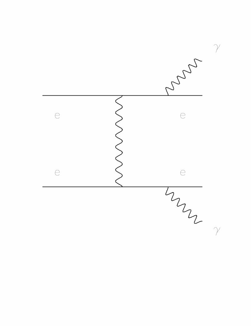
FOR SINGLE BREMSTRAHLUNG
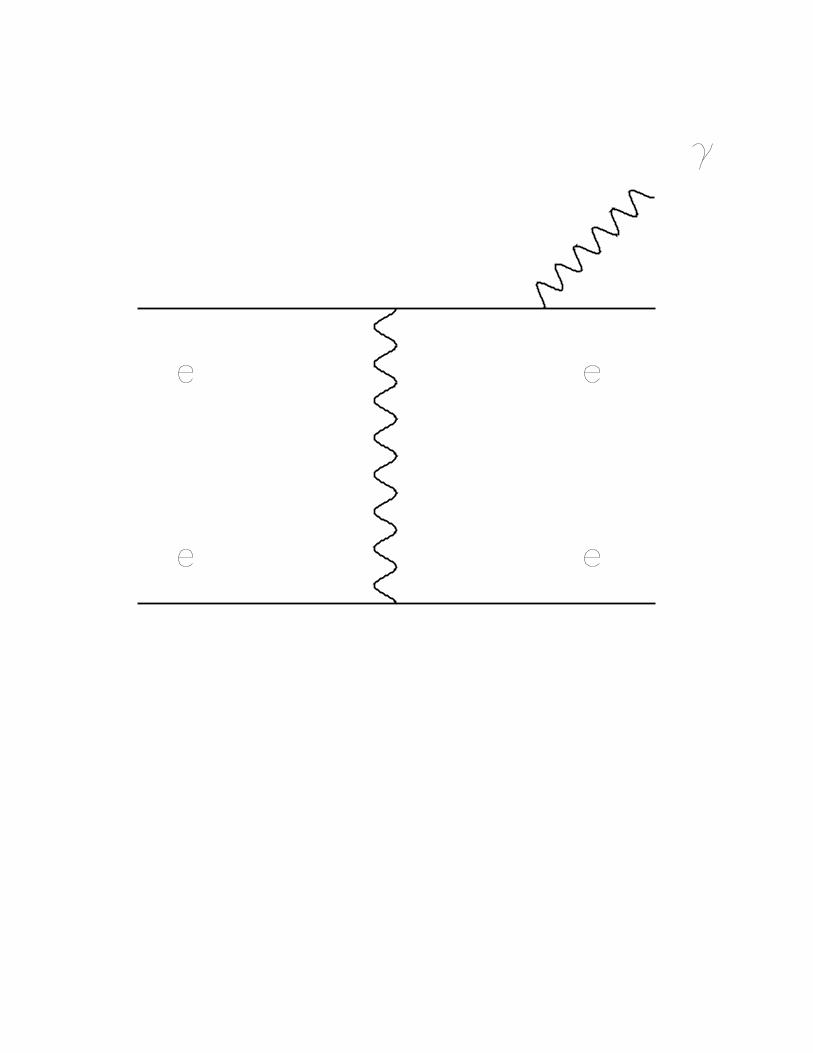
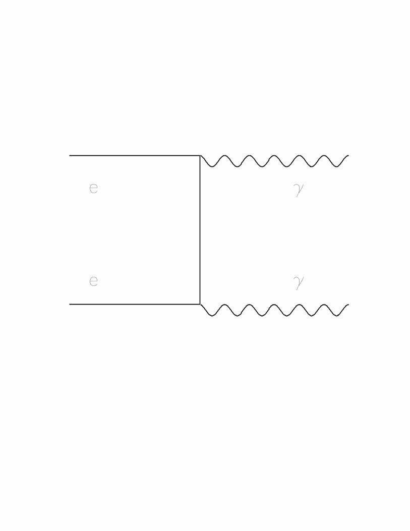
There are eight Feynman diagrams which contributeto the single bremstrahlung process in Bhabha scatter-ing: four (one radiated photon for each external particle)associated with the s channel, and another four with thet channel process. For application to photons being de-tected with the CMD2 luminosity monitor system, thegeneral calculation [9] is simplified for the limit of pho-tons emitted close to the incident beam axis and at ultra-relativistic electron energies. In this limit, only the fourt channel diagrams contribute and the double differentialcross section with respect to polar angle n = θγ = θE/me
and photon energy ω (energy fraction x ≡ ω/E) is givenby [12]:
d2σγ
dωdn= 4α r2
0
1
ω
n
(1 + n2)2[
I1 + (I2 + x2) ln(
4γ2 {1/x − 1})]
I1 = −(2 − x)2 +16n2
(1 + n2)2(1 − x)
I2 = 2(1 − x) −4n2
(1 + n2)2(1 − x)
where r0 is the classical electron radius.Since LMPSD will ultimately be used in conjunction
with the BGO calorimeter system which detects photonsabove an energy threshold ωth (to remove low energybackgrounds), this expression needs to be integrated fromωth to E ≡ Eγ
max ' Eebeam in order to obtain the QED
angular distribution of the single bremstrahlung photons.It is convenient to write ω = ωth, x = xth for notation inthe result below:
∫ E
ω
dωd2σγ
dωdn=
dσγ
dn= 4α r2
0
[
n
(1 + n2)2(4A + 2B + C + Z2) +
n3
(1 + n2)4(16A − 4B)
]
Zn =1
n2(xn − 1)
A = ln(E − ω) + Z1
B = ln 4γ2 ln(E − ω) + lnE ln(E + ω)1
2
(
(lnE)2 − (ln ω)2)
+
5
x lnω − lnE − Z1 lnE − ω
4γ2+
∞∑
1
Zn
C = Z2 lnω
4γ2 (E − ω)+
1
2(lnω − lnE) −
1
2
In order to write this in terms of the LMPSD ho-doscope variables x, y it is necessary to make a small an-gle approximation since x, y < 5 cm and z = 1.6 m (thedistance from the CMD2 collision vertex to LMPSD) andnote that:
n = γθ → ndn = γ2θdθdφ
2π'
γ2
2πsin θdθdφ =
γ2
2πdxdy
θ ' sin θ 'r
z=
√
x2 + y2
z→ n2 = γ2θ2 '
γ2
z2
(
x2 + y2)
.
Making these substitutions the result is as quoted:
σγ(x, y) =d2σγ
dxdy=
γ2
2π
E1
1(
1 + γ2
z2 (x2 + y2))2
+ E2
γ2
z2
(
x2 + y2)
(
1 + γ2
z2 (x2 + y2))4
E1 = 4A + 2B + C + Z2
E2 = 16A − 4B.
[1] D.H. Brown and W.A. Worstell., Technical report,Boston University Physics Department, 1995., BNL AGSE821 g−2 Note # 220. To be published in Physical Review
D.[2] S. Eidelman and F. Jegerlehner., Zeitschrift fur Physik,
C67, 585 1995.[3] Morris L. Swartz., SLAC-PUB-95-7001, Stanford Linear
Accelerator Center, CA, 1995.[4] J.R. Sapirstein et al., Physical Review D, 29, 2290 1984.[5] R.R. Akhmetshin et al., Preprint 95-35, Budker Insti-
tute of Nuclear Physics, Novosibirsk, Russia, 1995. To be
published in Physics Letters B.[6] V.M. Aulchenko et al., Preprint 87-36, Budker Institute
of Nuclear Physics, Novosibirsk, Russia, 1987.[7] Y.M. Shatunov et al., Technical report, Budker Institute
of Nuclear Physics, Novosibirsk, Russia, 1995.[8] L. Maiani et al., Technical report, INFN, Laboratori
Nazionali di Frascati, Italy, May 1995.[9] V.N. Baier et al., Physics Reports, 78, 293 1981.
[10] R.R. Akhmetshin et al., Technical report, Budker Insti-tute of Nuclear Physics, Novosibirsk, Russia, 1995.
[11] CERN., PAW - Physics Analysis Workstation, q121 edi-tion, 1995.
[12] S.I. Redin., Technical report, Budker Institute of NuclearPhysics, Novosibirsk, Russia, 1990.
6

TABLE I. Results of a five parameter fit. Total number of events is 9889. Useful result is ratio of background to signalevents.
Fit X-region Y -region Npixels χ2 Nγ Nbkgd Nbkgd/Nγ C
1 x0 − 2 : x0 + 2 y0 − 1 : y0 + 1 15 4.7567 7744.9 2144.1 0.2768 -2 x0 − 1 : x0 + 2 y0 − 2 : y0 + 1 16 4.4279 8075.4 1813.6 0.2246 -3 x0 − 1 : x0 + 1 y0 − 2 : y0 + 2 15 5.8754 7902.8 1986.2 0.2513 -4 x0 − 2 : x0 + 2 y0 − 2 : y0 + 2 25 3.3544 8238.5 1650.5 0.2003 -
FIG. 1. Schematic of the Bremstrahlung Luminosity Monitor Systems in VEPP-2M. Two BGO crystals 70 × 70 × 100mm3
are indicated as LMBGO, while the two planes of scintillating fibers in front of LMBGO are indicated as LMPSD.
FIG. 2. Schematic of Luminosity Monitor Position Sensitive Detector (LMPSD) hardware. Scintillating fibers are spliced toclear fibers (by index-matching epoxy) and mounted on 64 channel PMT in light tight insulating enclosure.
FIG. 3. Schematic for the LMPSD “CODER” electronics. HI-LO determination performed by four 32 bit priority encoders,while mean and differences are burned into two 2K PROMs. Events defined by zero difference are read out by CAMAC.
FIG. 4. View of LMPSD in the CMD2 Control Room shows two dimensional colour of single beam spot. VEPP-2M orbitchanges visibly widen and/or produce additional beam spots.
FIG. 5. The LMPSD data with self XY -trigger alone.
FIG. 6. The LMPSD data in anti-coincidence with an upstream scintillator.
FIG. 7. The LMPSD data in anti-coincidence with an upstream scintillator and in coincidence with the BGO calorimeterabove 200 MeV threshold.
FIG. 8. The best fit of the LMPSD data with the QED angular distribution.
FIG. 9. A slice of the LMPSD data with fit: on peak. The many curves are for the fit regions shown in Tab. I and showagreement with the data.
FIG. 10. A slice of the LMPSD data with fit: off peak. The many curves are for the fit regions shown in Tab. I and showhow much data is due to signal (under) and background (above curves).
FIG. 11. The background in the LMPSD data: difference of data with fit.
7
arXiv:acc-phys/9607003 v1 15 Jul 1996
5
5
32 bit PE
32
64
5
5
5
5
5
2k PROM
5
32
preamps
PMT
discriminators
32
32
32
32
Y
X
5
Y DiffC
A
M
A
C
Y Mean
LO Y
HI Y
LO X
HI X X Mean
X Diff
Y Clock
4
Event Select andData Buffer
4
1
5
Y Diff
Y Mean
X Clock
X Diff
X Mean
1

PMT
light guide fibers
scintillating fibers
light tight mu metal shield
insulating plate
LMPSD Data - Self Trigger
LMPSD Data with Veto and BGO

LMPSD Bkgd = Data - Fit
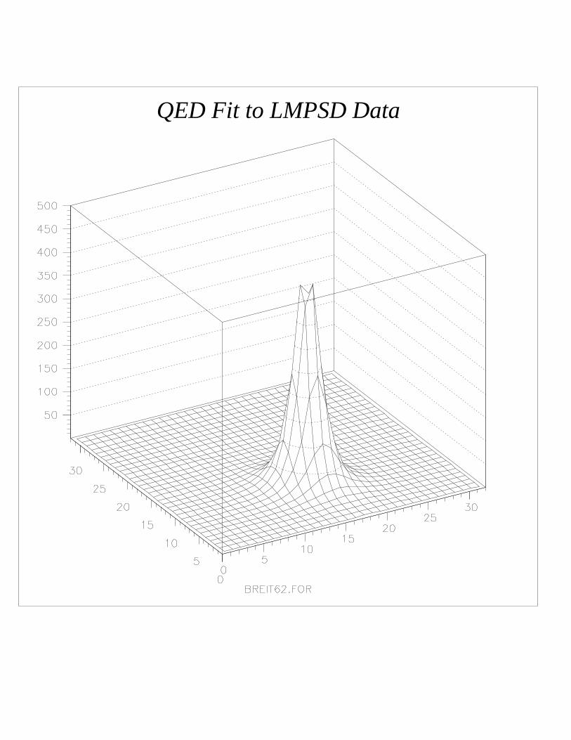
QED Fit to LMPSD Data
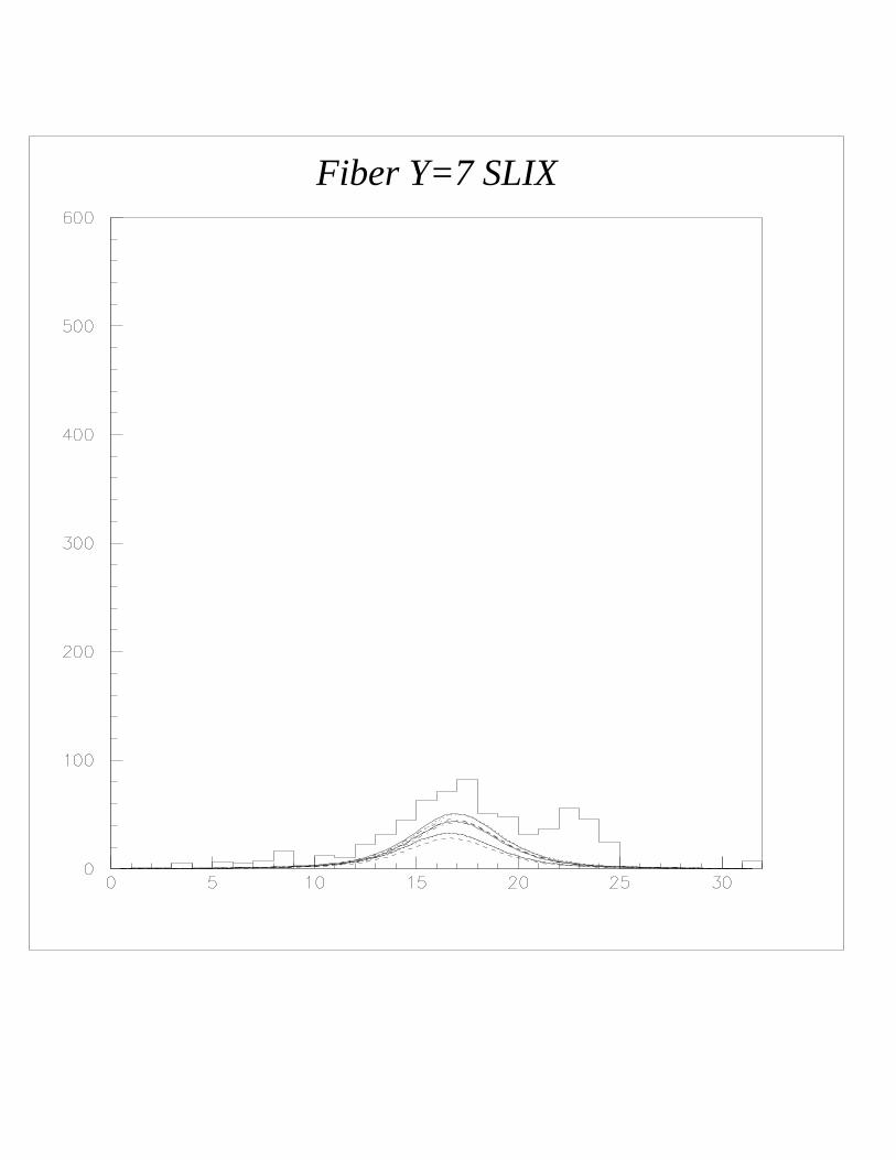
Fiber Y=7 SLIX
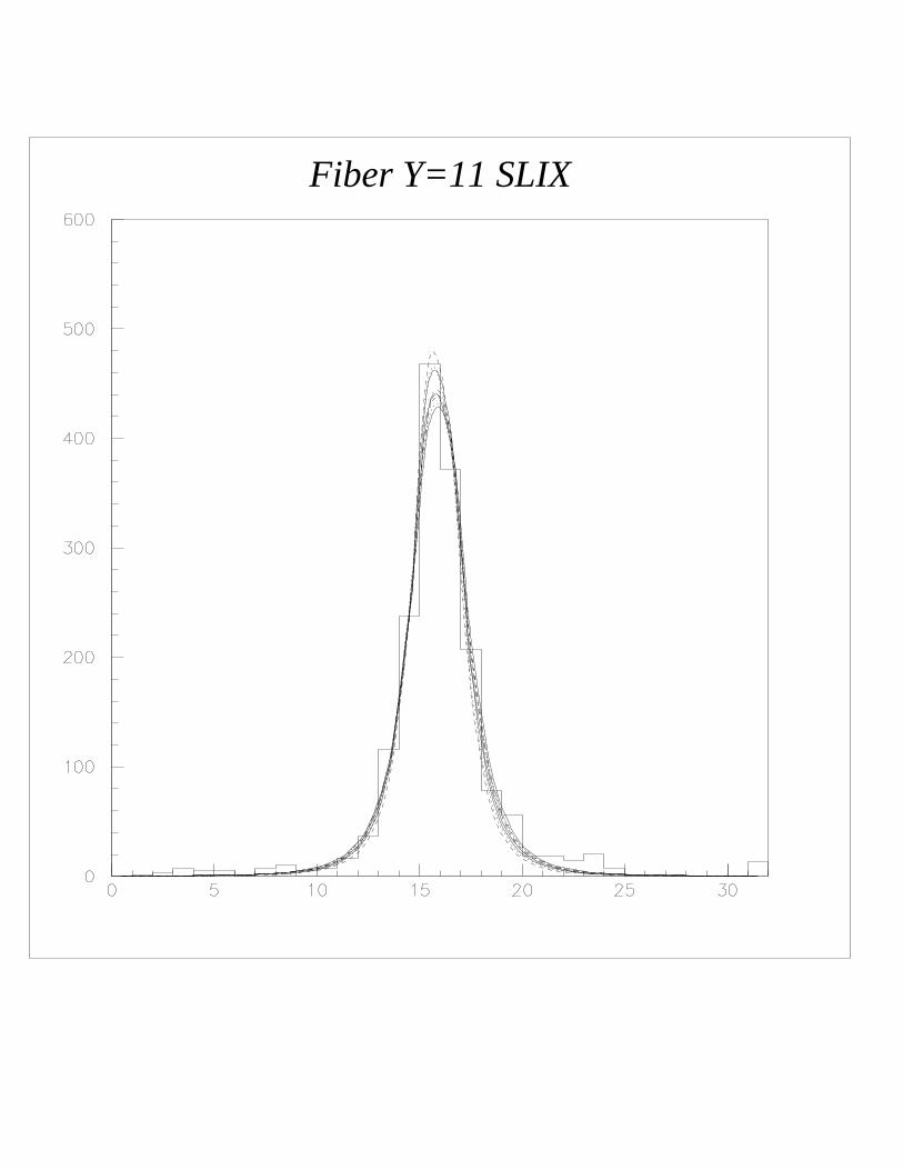
Fiber Y=11 SLIX
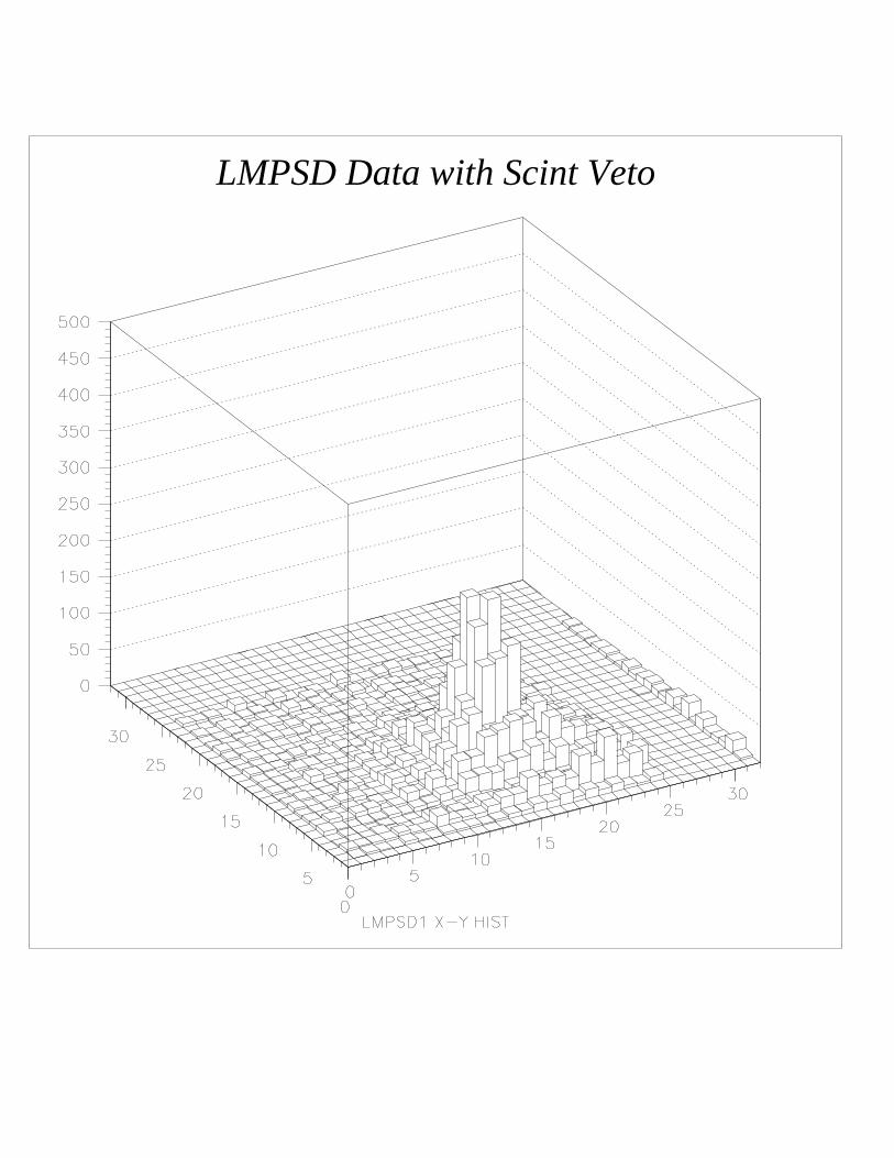
LMPSD Data with Scint Veto
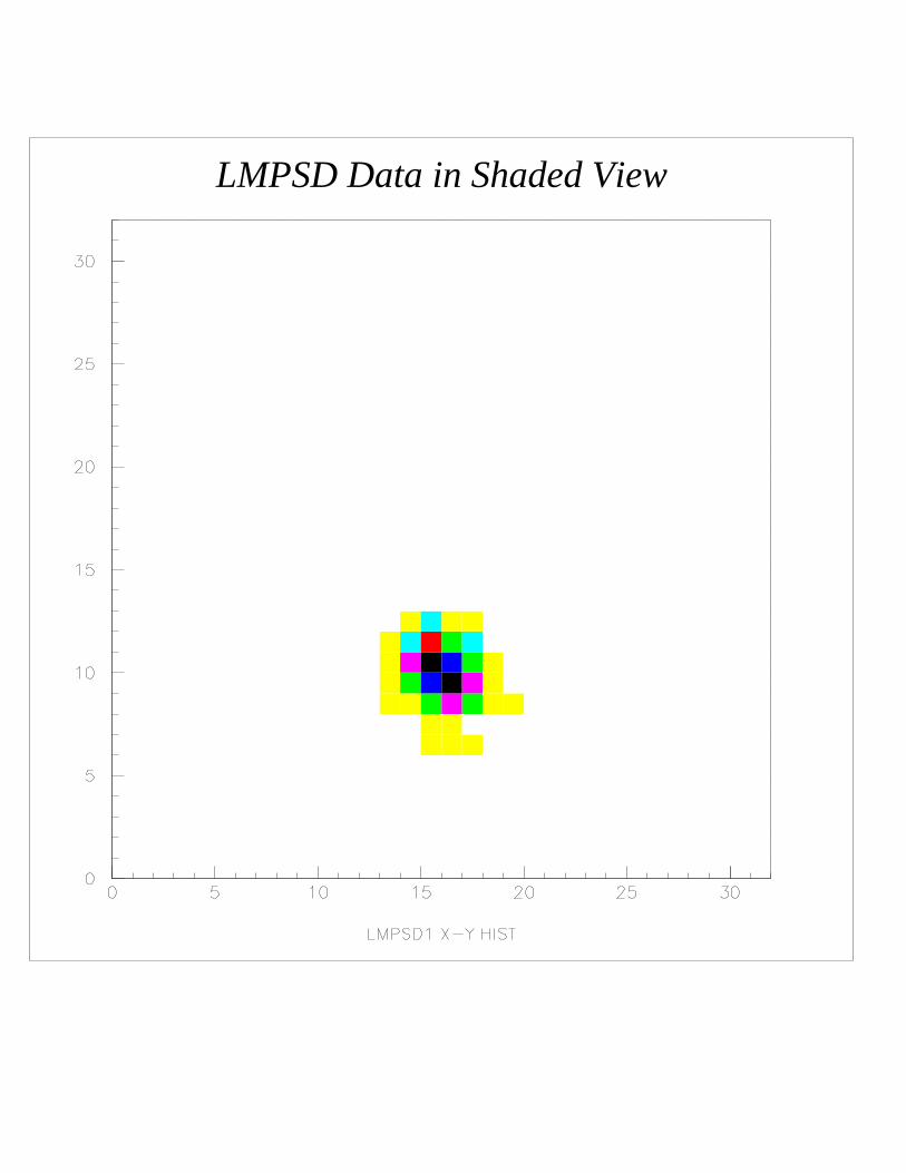
LMPSD Data in Shaded View


![The CLAS12 Forward Tagger · a CAD rendering of the FT. The calorimeter, the hodoscope, and the tracker are placed between the High Threshold Cherenkov Counter (HTCC) [4] and the](https://img.pdfslide.us/doc/110x75/5f9a1ed4e89f7a6d74367a7f/the-clas12-forward-tagger-a-cad-rendering-of-the-ft-the-calorimeter-the-hodoscope.jpg)