Embed Size (px)
Citation preview
Electromotive Force Resistor Circuits Connections in parallel and series
Kirchoff’s Rules Complex circuits made easy
RC Circuits Charging and discharging
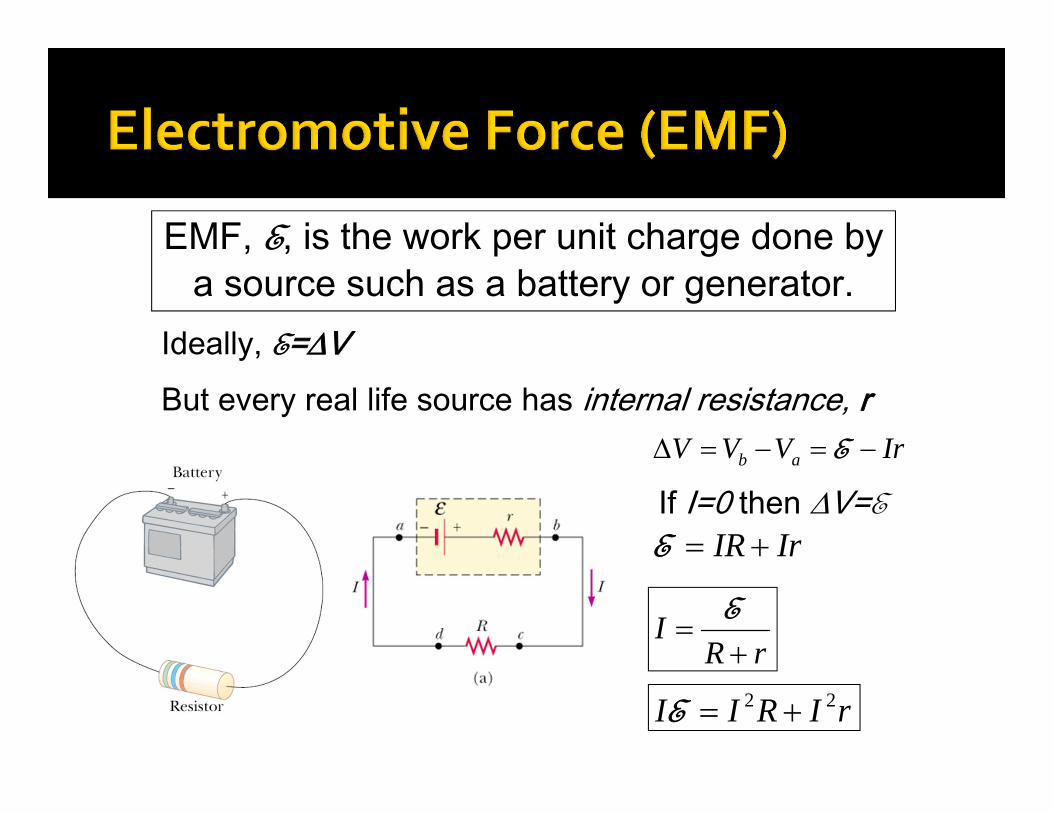
EMF, E, is the work per unit charge done by a source such as a battery or generator.
Ideally, E=VBut every real life source has internal resistance, r
IrVVV ab E
If I=0 then V=EIrIR E
rRI
E
rIRII 22 E
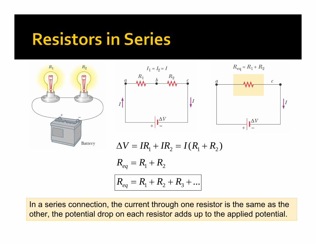
)( 2121 RRIIRIRV
21 RRReq
...321 RRRReq
In a series connection, the current through one resistor is the same as the other, the potential drop on each resistor adds up to the applied potential.
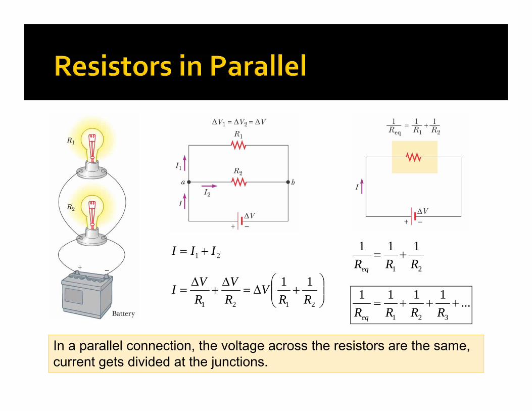
21 III
2121
11RR
VRV
RVI
21
111RRReq
...1111
321
RRRReq
In a parallel connection, the voltage across the resistors are the same, current gets divided at the junctions.
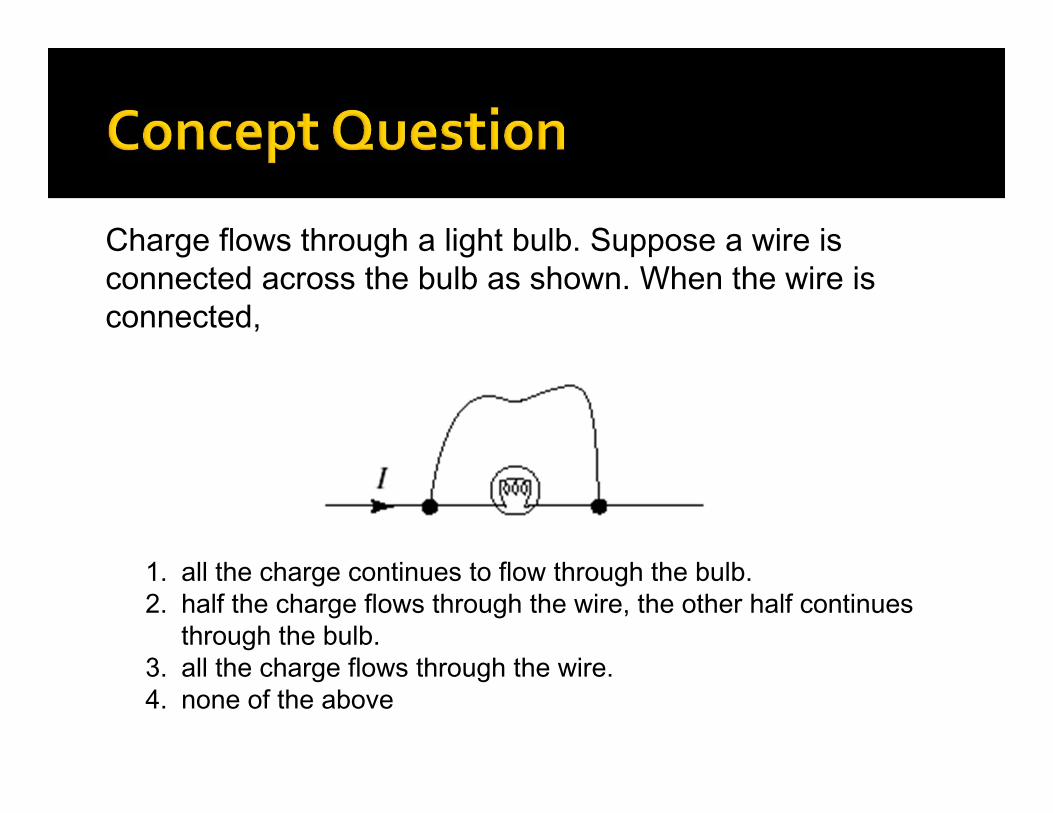
Charge flows through a light bulb. Suppose a wire is connected across the bulb as shown. When the wire is connected,
1. all the charge continues to flow through the bulb.2. half the charge flows through the wire, the other half continues
through the bulb.3. all the charge flows through the wire.4. none of the above
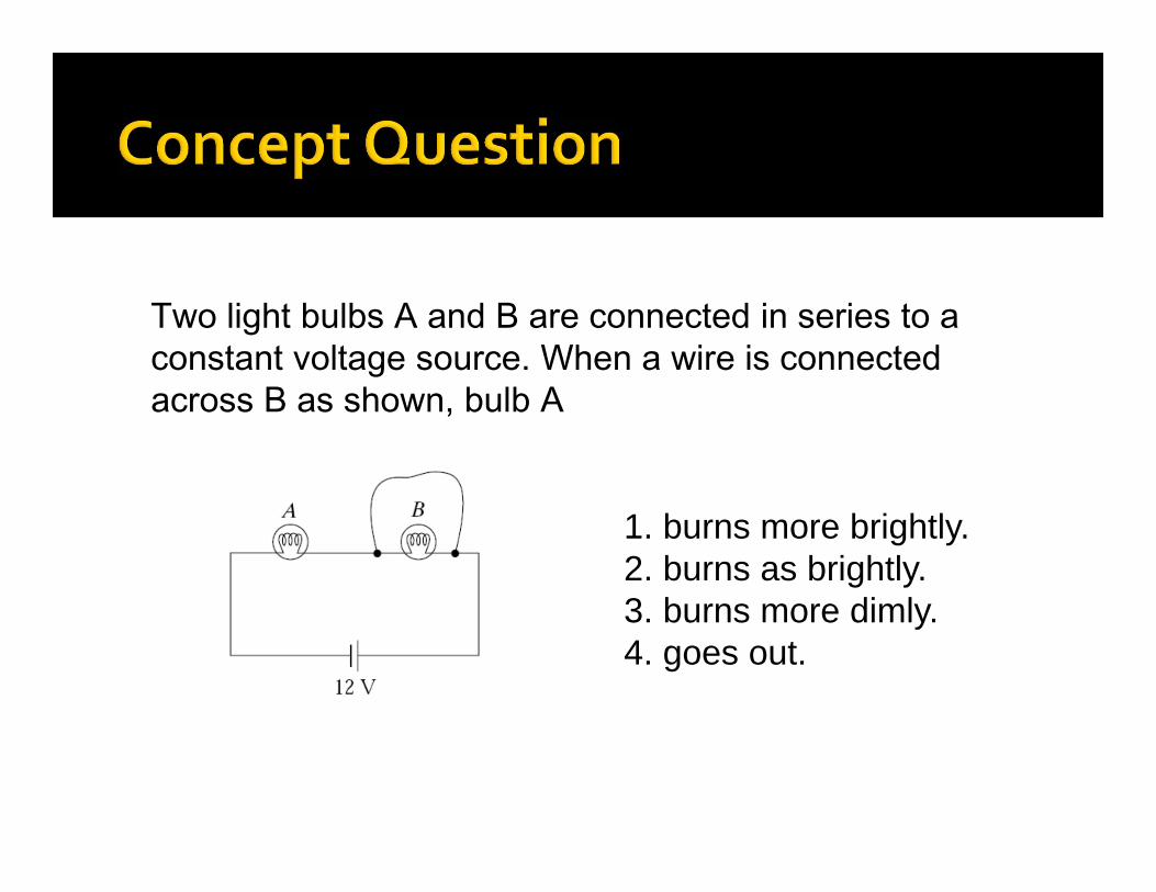
Two light bulbs A and B are connected in series to a constant voltage source. When a wire is connected across B as shown, bulb A
1. burns more brightly.2. burns as brightly.3. burns more dimly.4. goes out.
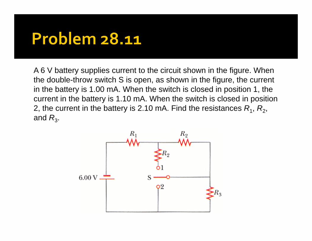
A 6 V battery supplies current to the circuit shown in the figure. When the double-throw switch S is open, as shown in the figure, the current in the battery is 1.00 mA. When the switch is closed in position 1, the current in the battery is 1.10 mA. When the switch is closed in position 2, the current in the battery is 2.10 mA. Find the resistances R1, R2, and R3.
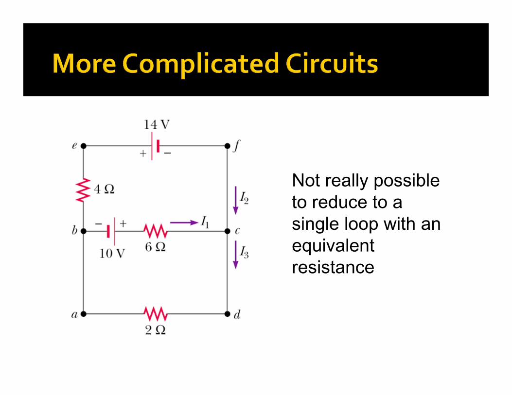
Not really possible to reduce to a single loop with an equivalent resistance
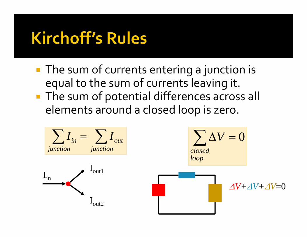
The sum of currents entering a junction is equal to the sum of currents leaving it.
The sum of potential differences across all elements around a closed loop is zero.
junction
outjunction
in II 0loopclosed
V
IinIout1
Iout2
V+V+V=0
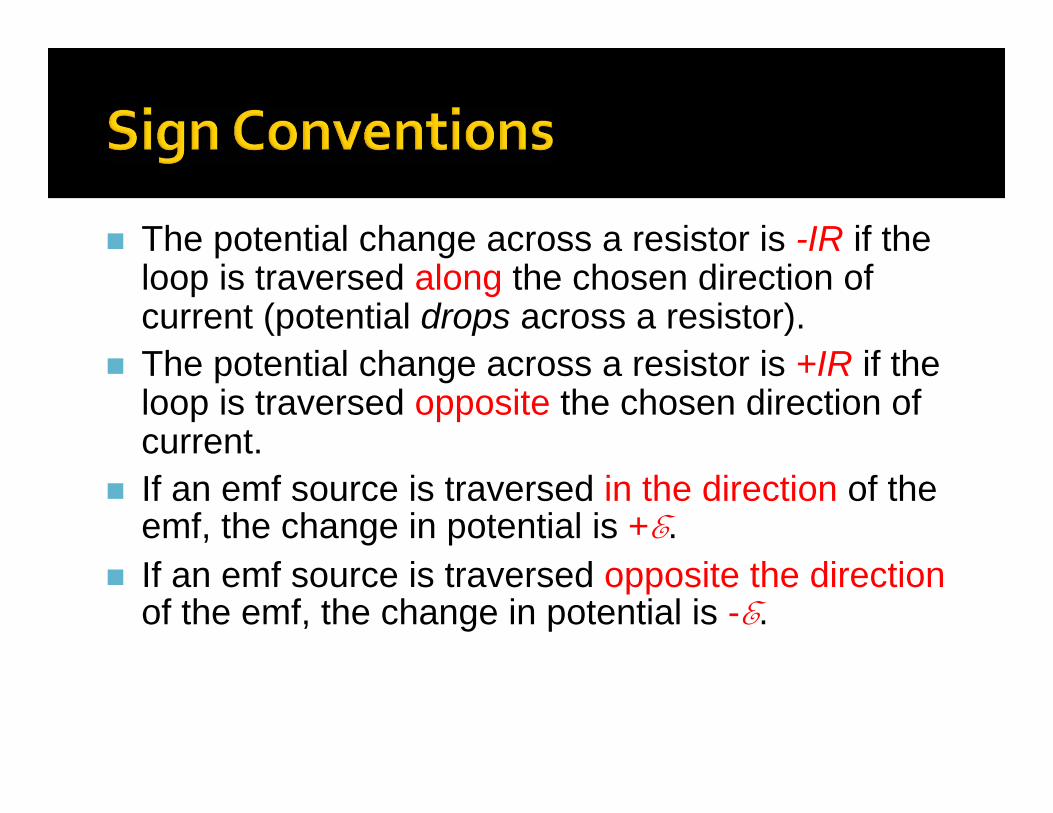
The potential change across a resistor is -IR if the loop is traversed along the chosen direction of current (potential drops across a resistor).
The potential change across a resistor is +IR if the loop is traversed opposite the chosen direction of current.
If an emf source is traversed in the direction of the emf, the change in potential is +E.
If an emf source is traversed opposite the directionof the emf, the change in potential is -E.
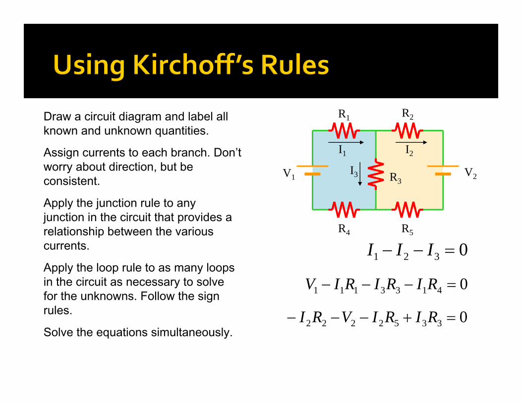
R1 R2
R4 R5
R3V1 V2
Draw a circuit diagram and label all known and unknown quantities.
Assign currents to each branch. Don’t worry about direction, but be consistent.
I1 I2
I3
Apply the junction rule to any junction in the circuit that provides a relationship between the various currents. 0321 IIIApply the loop rule to as many loops in the circuit as necessary to solve for the unknowns. Follow the sign rules.
04133111 RIRIRIV
Solve the equations simultaneously.03352222 RIRIVRI
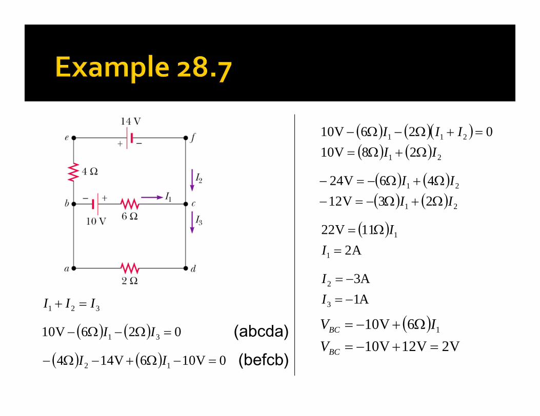
321 III
026V10 31 II (abcda) 0V106V144 12 II (befcb)
21
211
28V10026V10
IIIII
21
21
23V1246V24
IIII
A2
11V22
1
1
II
A1A3
3
2
II
V2V12V10
6V10 1
BC
BC
VIV
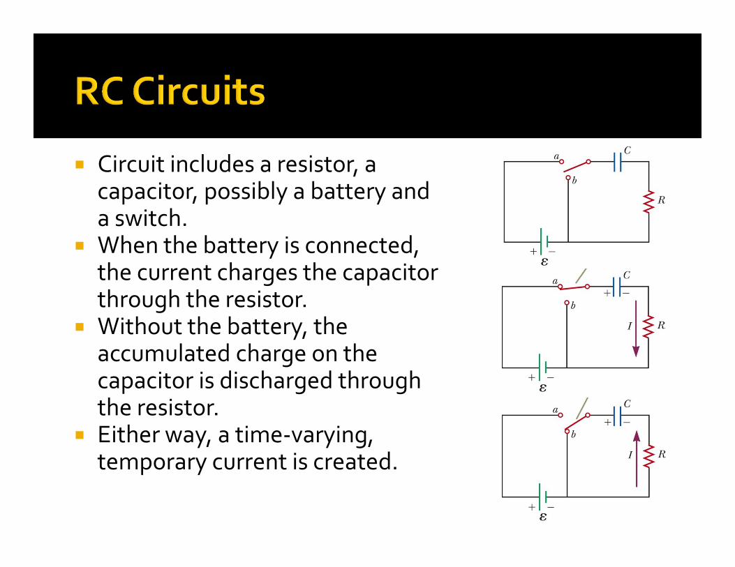
Circuit includes a resistor, a capacitor, possibly a battery and a switch.
When the battery is connected, the current charges the capacitor through the resistor.
Without the battery, the accumulated charge on the capacitor is discharged through the resistor.
Either way, a time‐varying, temporary current is created.
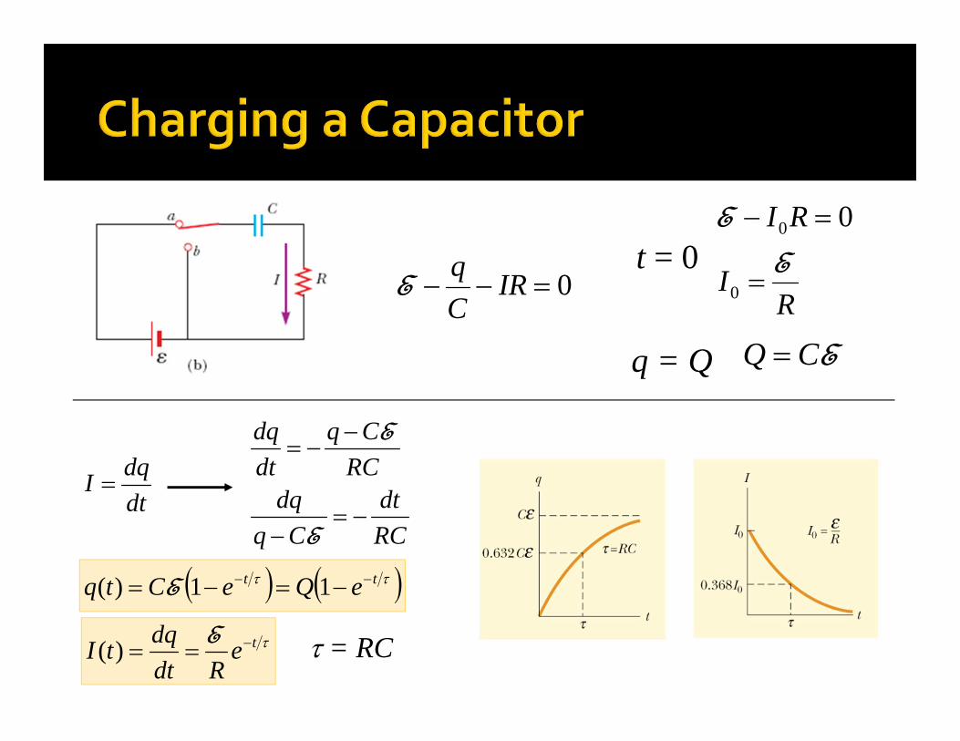
0 IRCqE
dtdqI
t = 0R
I
RIE
E
0
0 0
q = Q ECQ
RCdt
Cqdq
RCCq
dtdq
E
E
tt eQeCtq 11)( E
teRdt
dqtI E)( = RC
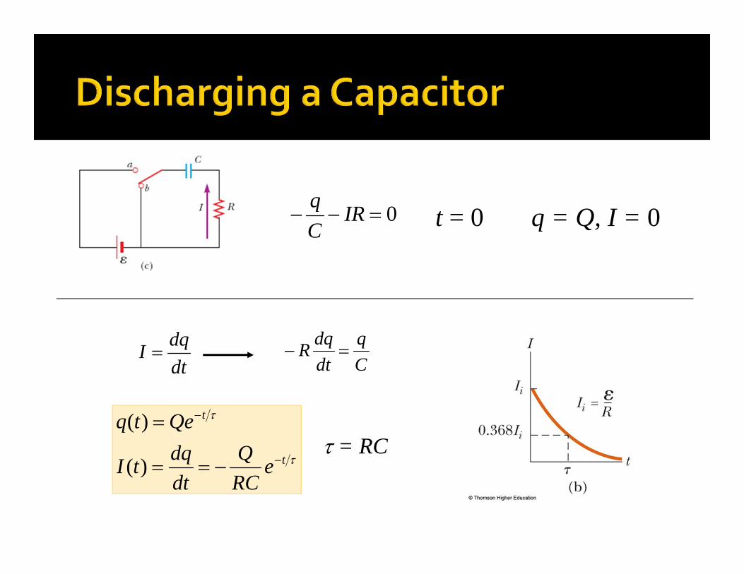
0 IRCq
Cq
dtdqR
q = Q, I = 0t = 0
dtdqI
t
t
eRCQ
dtdqtI
Qetq
)(
)(= RC
E = 10 V, R = 1 M and C = 1.5 F
Find I0, Q, How long to discharge half the maximum charge?
Maximum energy stored?
How long to release half of the stored energy?
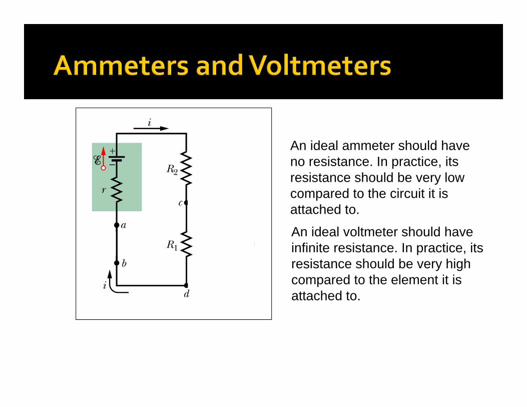
An ideal ammeter should have no resistance. In practice, its resistance should be very low compared to the circuit it is attached to.
An ideal voltmeter should have infinite resistance. In practice, its resistance should be very high compared to the element it is attached to.
EMF device as a charge pump Power and energy in circuits Loop and junction rules Resistors in series and parallel RC Circuits

Midterm 1 Review on Friday Midterm 1 on Monday Reading Assignment for Tuesday Chapter 29 – Magnetic Fields
WebAssign: Assignment 6 (due Friday, 11 PM)