Embed Size (px)
Citation preview
Electromagnetic models of the lightning return stroke
Yoshihiro Baba1 and Vladimir A. Rakov2
Received 24 February 2006; revised 22 August 2006; accepted 6 October 2006; published 16 February 2007.
[1] Lightning return-stroke models are needed for specifying the source in studying theproduction of transient optical emission (elves) in the lower ionosphere, the energeticradiation from lightning, and characterization of the Earth’s electromagnetic environment,as well as studying lightning interaction with various objects and systems. Reviewed hereare models based on Maxwell’s equations and referred to as electromagnetic models.These models are relatively new and most rigorous of all models suitable for computinglightning electromagnetic fields. Maxwell’s equations are numerically solved to yield thedistribution of current along the lightning channel. Different numerical techniques,including the method of moments (MoM) and the finite difference time domain (FDTD)method, are employed. In order to achieve a desirable current-wave propagation speed(lower than the speed of light in air), the channel-representing wire is embedded in adielectric (other than air) or loaded by additional distributed series inductance. Capacitiveloading has been also suggested. The artificial dielectric medium is used only forfinding the distribution of current along the lightning channel, after which the channel isallowed to radiate in air. Resistive loading is used to control current attenuation withheight. In contrast with distributed circuit and so-called engineering models,electromagnetic return-stroke models allow a self-consistent full-wave solution for bothlightning-current distribution and resultant electromagnetic fields. In this review, wediscuss advantages and disadvantages of four return-stroke channel representations: aperfectly conducting/resistive wire in air, a wire embedded in a dielectric (other than air), awire in air loaded by additional distributed series inductance, and a wire in air havingadditional distributed shunt capacitance. Further, we describe and compare differentmethods of excitation used in electromagnetic return-stroke models: closing a chargedvertical wire at its bottom with a specified grounded circuit, a delta-gap electric fieldsource, and a lumped current source. Finally, we review and compare representativenumerical techniques used in electromagnetic modeling of the lightning return stroke:MoMs in the time and frequency domains and the FDTD method. We additionallyconsider the so-called hybrid model of the lightning return stroke that employs acombination of electromagnetic and circuit theories and compare this model toelectromagnetic models.
Citation: Baba, Y., and V. A. Rakov (2007), Electromagnetic models of the lightning return stroke, J. Geophys. Res., 112, D04102,
doi:10.1029/2006JD007222.
1. Introduction
[2] Lightning return-stroke models are needed in a varietyof geophysical studies, including the production of transientoptical emission (elves) in the lower ionosphere [e.g.,Krider, 1994; Rakov and Tuni, 2003; Lu, 2006], the ener-getic radiation from lightning [e.g., Inan and Lehtinen,2005], and characterization of the lightning electromagneticenvironment [e.g., Kordi et al., 2003b], as well as instudying lightning effects on various objects and systems
[e.g., Moini et al., 1998]. Clearly, conclusions drawnfrom these studies are influenced by the choice andvalidity of lightning source model employed [e.g.,Thottappillil et al., 1997; Rakov and Tuni, 2003]. Rakovand Uman [1998], based on governing equations, havecategorized return-stroke models into four classes: gasdynamic models, electromagnetic models, distributed cir-cuit models, and ‘‘engineering’’ models. Out of these fourclasses, electromagnetic models and engineering modelsare most widely used in lightning electromagnetic fieldcalculations.[3] Engineering return-stroke models are equations relat-
ing the longitudinal current along the lightning channel atany height and any time to the current at the channel origin(the origin is usually situated at ground level, but can be atthe top of a tall grounded strike object [e.g., Rachidi et al.,
JOURNAL OF GEOPHYSICAL RESEARCH, VOL. 112, D04102, doi:10.1029/2006JD007222, 2007ClickHere
for
FullArticle
1Department of Electrical Engineering, Doshisha University, Kyoto,Japan.
2Department of Electrical and Computer Engineering, University ofFlorida, Gainesville, Florida, USA.
Copyright 2007 by the American Geophysical Union.0148-0227/07/2006JD007222$09.00
D04102 1 of 17
2002]). The return-stroke wavefront speed in these modelscan be set arbitrarily, since it is one of the input parameters.Engineering return-stroke models have been reviewed byNucci et al. [1990], Thottappillil and Uman [1993],Thottappillil et al. [1997], Rakov and Uman [1998], andGomes and Cooray [2000].[4] Distributed circuit models of the lightning return
stroke usually consider the lightning channel as an R-L-Ctransmission line [e.g., Mattos and Christopoulos, 1988;Baum and Baker, 1990], where R, L, and C are seriesresistance, series inductance, and shunt capacitance, all perunit length, respectively. In an R-L-C transmission linemodel, voltage and current are the solutions of the telegra-pher’s equations. Note that the telegrapher’s equations canbe derived from Maxwell’s equations assuming that theelectromagnetic waves guided by the transmission line havea transverse electromagnetic (TEM) field structure. Strictlyspeaking, the latter assumption is not valid for a verticalconductor above ground. Indeed, any current wave suffersattenuation as it propagates upward along a vertical con-ductor, except for the special (unrealistic) case of a zero-radius vertical perfectly conducting wire excited at itsbottom by an infinitesimal current source [Thottappillil etal., 2001], and the resultant electromagnetic field structureis non-TEM [e.g., Kordi et al., 2002, 2003a; Baba andRakov, 2003, 2005b]. Clearly, an incorrect assumption onthe electromagnetic field structure (e.g., TEM when it isactually non-TEM) in the vicinity of lightning channelwill result in an incorrect current distribution along thechannel (as discussed, for example, by Baba and Rakov[2003]).[5] Electromagnetic return-stroke models are based on
Maxwell’s equations [Rakov and Uman, 1998]. These arerelatively new and most rigorous (no TEM assumption)models suitable for specifying the source in studyinglightning interaction with various systems and with theenvironment. In this class of models, Maxwell’s equationsare solved to yield the distribution of current along thelightning channel using numerical techniques, such asthe method of moments (MoM) [Harrington, 1968; VanBaricum and Miller, 1972; Miller et al., 1973] and the finitedifference time domain (FDTD) method [Yee, 1966]. Theresultant distribution of channel current can be used tocompute electric and magnetic fields radiated by the light-ning channel. In order to reduce the speed of current wavepropagating along the channel-representing wire to a valuelower than the speed of light in air, c, a wire is embeddedin a dielectric (other than air) [e.g., Moini et al., 1997,2000] or loaded by additional distributed series inductance[e.g., Kato et al., 1999]. Capacitive loading has been alsosuggested [Bonyadi-ram et al., 2004]. In contrast withdistributed-circuit and engineering models, electromagneticreturn-stroke models allow a self-consistent full-wave solu-tion for both lightning-current distribution and resultantelectromagnetic fields. One of the advantages of the useof electromagnetic models, although it may be computa-tionally expensive, is that one does not need to employany model of field-to-conductor coupling in analyzinglightning-induced effects on electrical circuits [e.g.,Pokharel et al., 2003; Tatematsu et al., 2004]. Electromag-netic models are generally capable of reproducing most
salient features of observed electric and magnetic fields atdistances ranging from tens of meters to hundreds ofkilometers [e.g., Moini et al., 2000; Baba and Ishii, 2003;Shoory et al., 2005].[6] The first peer-reviewed journal paper concerned
with an electromagnetic model was published in 1987[Podgorski and Landt, 1987], and more than a dozenof journal papers and a very large number of confer-ence papers were published during the last seven yearsor so. The amount of published material on lightningelectromagnetic models is presently such that the area isin need of consolidating review. Interest in usingelectromagnetic models continues to grow, in partbecause of availability of numerical codes and increasedcomputer capabilities. At the same time certain aspects(or even the concept) of these models are misunder-stood by some researchers and appear to be in need ofclarification.[7] In this paper, we classify electromagnetic models of
the lightning return stroke, proposed or used as of today, interms of the channel representation, the excitation method,and the employed numerical technique (or procedure).Additionally considered here is the so-called hybridelectromagnetic/circuit theory (HEM) model [Visacro et al.,2002], which employs electric scalar and magnetic vectorpotentials for taking account of electromagnetic couplingbut is formulated in terms of circuit quantities, voltages andcurrents. Since the HEM model, on the one hand, yields anon-TEM close electromagnetic field structure (as do elec-tromagnetic models) and, on the other hand, apparentlyconsiders electric and magnetic fields as decoupled (as indistributed circuit models), it occupies an intermediate placebetween electromagnetic and distributed circuit models. Wewill show in this paper that its predictions are similar tothose of electromagnetic models. Application of the HEMmodel to lightning return-stroke studies and to analyzing theinteraction of lightning with grounded objects is describedby Visacro and Silveira [2004] and by Visacro and Soares[2005], respectively.[8] The structure of this paper is as follows. In section 2,
we show that a current wave necessarily suffers attenuation(dispersion to be exact) as it propagates upward along avertical non-zero-thickness wire above perfectly conductingground excited at its bottom by a lumped source, even if thewire has no ohmic losses, which is a distinctive feature ofelectromagnetic return-stroke models. In section 3, weclassify electromagnetic return-stroke models into fourtypes depending on lightning channel representation usedto find the distribution of current along the channel: aperfectly conducting or resistive wire in air, a wire embed-ded in a dielectric (other than air), a wire in air loaded byadditional distributed series inductance, and two wires in airhaving additional distributed shunt capacitance. In section 4,we describe methods of excitation used in electromagneticreturn-stroke models: closing a charged vertical wire at itsbottom with a specified impedance (or circuit), a delta-gap electric field source, and a lumped current source. Insection 5, we review representative numerical proceduresfor solving Maxwell’s equations used in electromagneticmodels of the lightning return stroke: MoMs in the time andfrequency domains, and the FDTD method. In Appendix A,
D04102 BABA AND RAKOV: LIGHTNING RETURN STROKE MODELS
2 of 17
D04102
we compare current distributions along a vertical wirecalculated using an electromagnetic model with that calcu-lated using the HEM model.
2. General Approach to Finding the CurrentDistribution Along a Vertical Perfectly ConductingWire Above Ground
[9] All electromagnetic return-stroke models involve arepresentation of the lightning channel as a non-zero-thickness vertical wire. In this section, using Chen’s [1983]analytical equation, we show that a current wave necessarilysuffers attenuation as it propagates along a vertical wire ofuniform nonzero thickness that is located above perfectlyconducting ground and excited at its bottom by a lumpedsource, even if the wire has no ohmic losses. This effect,generally known in the radio science community, but appar-ently not in the lightning research community [e.g., Bermudezet al., 2003], is usually attributed to radiation losses. Here, weshow that current attenuation (or, more generally, dispersion,to be understood here as changes in pulse waveshape) isnecessary to satisfy the boundary condition on the tangentialelectric field on the surface of vertical wire.
2.1. Current Distribution Along a Vertical PerfectlyConducting Wire Above Ground
[10] Chen [1983] has derived an approximate analyticalequation for the transient current I(z0, t) along an infinitelylong perfectly conducting cylinder in air excited in themiddle by a zero-length voltage source generating stepvoltage V. This equation is reproduced below.
I z0; tð Þ ¼ 2V
htan�1 p
2 lnffiffiffiffiffiffiffiffiffiffiffiffiffiffiffiffiffiffic2t2 � z02
p=a
� �0@
1A; ð1Þ
where h is free space impedance (120p W), ln is the naturallogarithm, and a is the radius of the cylinder. Note thatChen’s equation (1) yields results that are almost identical to
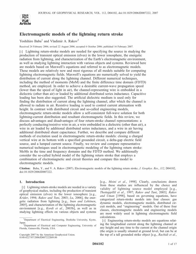
those given by exact formula of Wu [1961]. If we apply(1) to a vertical cylinder on flat perfectly conducting groundexcited at its bottom by a zero-length step-voltage source,we have only to multiply the magnitude of resultant currentby 2 in order to account for the image source. Chen’sanalytical equation (1) can be used in testing the accuracy ofnumerical techniques employed in electromagnetic modelsof the lightning return stroke.[11] Figure 1 shows current waveforms at different
heights along a vertical perfectly conducting wire of radius0.23 m in air above ground excited at its bottom by a zero-length source that produces a ramp-front wave having amagnitude of 5 MV and a risetime of 1 ms. Note that weobtained the response to this ramp-front voltage wave usingnumerical convolution since (1) is the solution for a stepvoltage excitation.[12] It is clear from Figure 1 that a current wave suffers
attenuation as it propagates along the vertical perfectlyconducting wire above ground. We will show in section 5.3that current waveforms calculated using the MoM in the timeand frequency domains and the FDTD method agree wellwith those calculated using Chen’s equation.
2.2. Mechanism of Attenuation of Current Wavein the Absence of Ohmic Losses
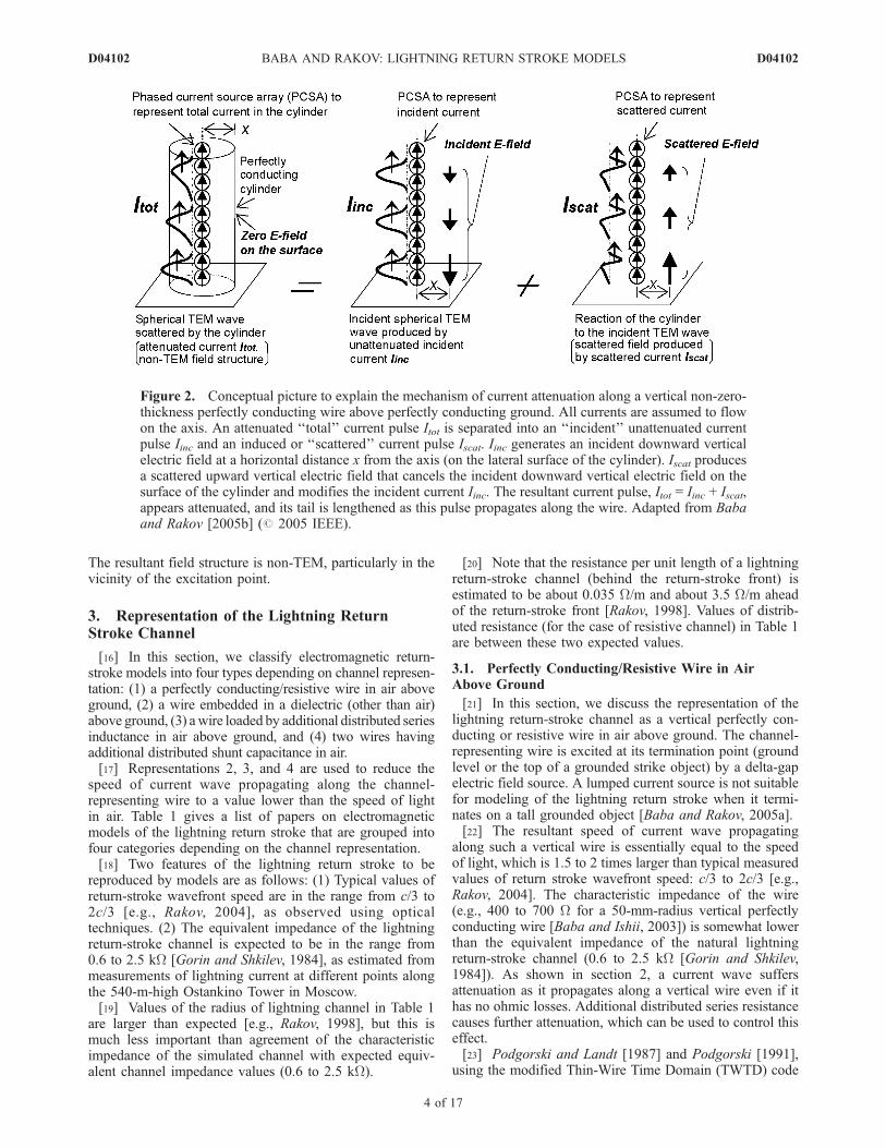
[13] According to analytical equation (1), any currentwave suffers attenuation as it propagates upward along avertical perfectly conducting wire above flat perfectly con-ducting ground excited at its bottom by a lumped source(the same result follows from numerical solution ofMaxwell’s equations [e.g., Kordi et al., 2002, 2003a; Babaand Rakov, 2003, 2005b]), except for the ideal (unrealistic)case of a zero-thickness wire excited by a zero-lengthsource [Thottappillil et al., 2001]. In this section, we discussthe mechanism of current attenuation in the absence ofohmic losses.[14] Baba and Rakov [2005b] visualized the mechanism
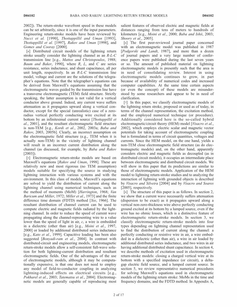
of attenuation of current wave propagating along a verticalnon-zero-thickness perfectly conducting wire as illustratedin Figure 2. A reference (no interaction with the wire, noattenuation) positive current pulse Iinc propagating upwardgenerates an incident spherical TEM wave [Thottappillil etal., 2001], with vertical electric field component on thesurface of the wire being directed downward. Cancellationof this field, as required by the boundary condition on thetangential electric field on the surface of a perfectly con-ducting wire, gives rise to an induced or ‘‘scattered’’ currentIscat. This scattered current Iscat modifies Iinc, so that theresultant total current pulse Itot appears attenuated as itpropagates along the vertical wire. The attenuation of thetotal current pulse is accompanied by the lengthening of itstail, such that the total charge transfer is independent ofheight. The electromagnetic field structure associated withan attenuated current distribution along a vertical wire isnon-TEM. Baba and Rakov [2005b] have shown that thecurrent attenuation becomes more pronounced as (1) thethickness of vertical wire increases, (2) the source heightdecreases, (3) the frequency increases, and (4) the heightabove the excitation point decreases.[15] In summary, current attenuation (or, more generally,
dispersion) is necessary to satisfy the boundary condition onthe tangential electric field on the surface of vertical wire.
Figure 1. Current waveforms at different heights calcu-lated using Chen’s analytical equation (see (1)) for a verticalperfectly conducting cylinder of radius 0.23 m in air aboveperfectly conducting ground excited at its bottom by a zero-length voltage source. The source produces a ramp wavehaving a magnitude of 5 MV and a risetime of 1 ms.
D04102 BABA AND RAKOV: LIGHTNING RETURN STROKE MODELS
3 of 17
D04102
The resultant field structure is non-TEM, particularly in thevicinity of the excitation point.
3. Representation of the Lightning ReturnStroke Channel
[16] In this section, we classify electromagnetic return-stroke models into four types depending on channel represen-tation: (1) a perfectly conducting/resistive wire in air aboveground, (2) a wire embedded in a dielectric (other than air)above ground, (3) a wire loaded by additional distributed seriesinductance in air above ground, and (4) two wires havingadditional distributed shunt capacitance in air.[17] Representations 2, 3, and 4 are used to reduce the
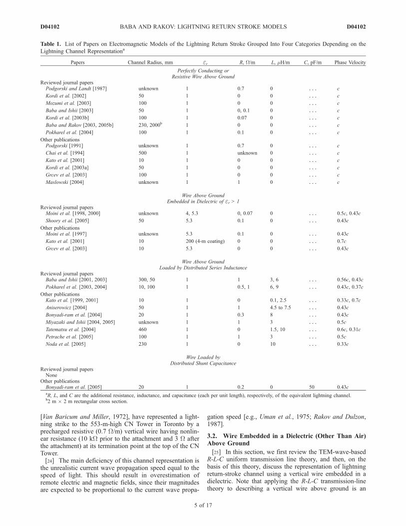
speed of current wave propagating along the channel-representing wire to a value lower than the speed of lightin air. Table 1 gives a list of papers on electromagneticmodels of the lightning return stroke that are grouped intofour categories depending on the channel representation.[18] Two features of the lightning return stroke to be
reproduced by models are as follows: (1) Typical values ofreturn-stroke wavefront speed are in the range from c/3 to2c/3 [e.g., Rakov, 2004], as observed using opticaltechniques. (2) The equivalent impedance of the lightningreturn-stroke channel is expected to be in the range from0.6 to 2.5 kW [Gorin and Shkilev, 1984], as estimated frommeasurements of lightning current at different points alongthe 540-m-high Ostankino Tower in Moscow.[19] Values of the radius of lightning channel in Table 1
are larger than expected [e.g., Rakov, 1998], but this ismuch less important than agreement of the characteristicimpedance of the simulated channel with expected equiv-alent channel impedance values (0.6 to 2.5 kW).
[20] Note that the resistance per unit length of a lightningreturn-stroke channel (behind the return-stroke front) isestimated to be about 0.035 W/m and about 3.5 W/m aheadof the return-stroke front [Rakov, 1998]. Values of distrib-uted resistance (for the case of resistive channel) in Table 1are between these two expected values.
3.1. Perfectly Conducting/Resistive Wire in AirAbove Ground
[21] In this section, we discuss the representation of thelightning return-stroke channel as a vertical perfectly con-ducting or resistive wire in air above ground. The channel-representing wire is excited at its termination point (groundlevel or the top of a grounded strike object) by a delta-gapelectric field source. A lumped current source is not suitablefor modeling of the lightning return stroke when it termi-nates on a tall grounded object [Baba and Rakov, 2005a].[22] The resultant speed of current wave propagating
along such a vertical wire is essentially equal to the speedof light, which is 1.5 to 2 times larger than typical measuredvalues of return stroke wavefront speed: c/3 to 2c/3 [e.g.,Rakov, 2004]. The characteristic impedance of the wire(e.g., 400 to 700 W for a 50-mm-radius vertical perfectlyconducting wire [Baba and Ishii, 2003]) is somewhat lowerthan the equivalent impedance of the natural lightningreturn-stroke channel (0.6 to 2.5 kW [Gorin and Shkilev,1984]). As shown in section 2, a current wave suffersattenuation as it propagates along a vertical wire even if ithas no ohmic losses. Additional distributed series resistancecauses further attenuation, which can be used to control thiseffect.[23] Podgorski and Landt [1987] and Podgorski [1991],
using the modified Thin-Wire Time Domain (TWTD) code
Figure 2. Conceptual picture to explain the mechanism of current attenuation along a vertical non-zero-thickness perfectly conducting wire above perfectly conducting ground. All currents are assumed to flowon the axis. An attenuated ‘‘total’’ current pulse Itot is separated into an ‘‘incident’’ unattenuated currentpulse Iinc and an induced or ‘‘scattered’’ current pulse Iscat. Iinc generates an incident downward verticalelectric field at a horizontal distance x from the axis (on the lateral surface of the cylinder). Iscat producesa scattered upward vertical electric field that cancels the incident downward vertical electric field on thesurface of the cylinder and modifies the incident current Iinc. The resultant current pulse, Itot = Iinc + Iscat,appears attenuated, and its tail is lengthened as this pulse propagates along the wire. Adapted from Babaand Rakov [2005b] (# 2005 IEEE).
D04102 BABA AND RAKOV: LIGHTNING RETURN STROKE MODELS
4 of 17
D04102
[Van Baricum and Miller, 1972], have represented a light-ning strike to the 553-m-high CN Tower in Toronto by aprecharged resistive (0.7 W/m) vertical wire having nonlin-ear resistance (10 kW prior to the attachment and 3 W afterthe attachment) at its termination point at the top of the CNTower.[24] The main deficiency of this channel representation is
the unrealistic current wave propagation speed equal to thespeed of light. This should result in overestimation ofremote electric and magnetic fields, since their magnitudesare expected to be proportional to the current wave propa-
gation speed [e.g., Uman et al., 1975; Rakov and Dulzon,1987].
3.2. Wire Embedded in a Dielectric (Other Than Air)Above Ground
[25] In this section, we first review the TEM-wave-basedR-L-C uniform transmission line theory, and then, on thebasis of this theory, discuss the representation of lightningreturn-stroke channel using a vertical wire embedded in adielectric. Note that applying the R-L-C transmission-linetheory to describing a vertical wire above ground is an
Table 1. List of Papers on Electromagnetic Models of the Lightning Return Stroke Grouped Into Four Categories Depending on the
Lightning Channel Representationa
Papers Channel Radius, mm er R, W/m L, mH/m C, pF/m Phase Velocity
Perfectly Conducting orResistive Wire Above Ground
Reviewed journal papersPodgorski and Landt [1987] unknown 1 0.7 0 � � � c
Kordi et al. [2002] 50 1 0 0 � � � c
Mozumi et al. [2003] 100 1 0 0 � � � c
Baba and Ishii [2003] 50 1 0, 0.1 0 � � � c
Kordi et al. [2003b] 100 1 0.07 0 � � � c
Baba and Rakov [2003, 2005b] 230, 2000b 1 0 0 � � � c
Pokharel et al. [2004] 100 1 0.1 0 � � � c
Other publicationsPodgorski [1991] unknown 1 0.7 0 � � � c
Chai et al. [1994] 500 1 unknown 0 � � � c
Kato et al. [2001] 10 1 0 0 � � � c
Kordi et al. [2003a] 50 1 0 0 � � � c
Grcev et al. [2003] 100 1 0 0 � � � c
Maslowski [2004] unknown 1 1 0 � � � c
Wire Above GroundEmbedded in Dielectric of er > 1
Reviewed journal papersMoini et al. [1998, 2000] unknown 4, 5.3 0, 0.07 0 � � � 0.5c, 0.43c
Shoory et al. [2005] 50 5.3 0.1 0 � � � 0.43c
Other publicationsMoini et al. [1997] unknown 5.3 0.1 0 � � � 0.43c
Kato et al. [2001] 10 200 (4-m coating) 0 0 � � � 0.7c
Grcev et al. [2003] 10 5.3 0 0 � � � 0.43c
Wire Above GroundLoaded by Distributed Series Inductance
Reviewed journal papersBaba and Ishii [2001, 2003] 300, 50 1 1 3, 6 � � � 0.56c, 0.43c
Pokharel et al. [2003, 2004] 10, 100 1 0.5, 1 6, 9 � � � 0.43c, 0.37c
Other publicationsKato et al. [1999, 2001] 10 1 0 0.1, 2.5 � � � 0.33c, 0.7c
Aniserowicz [2004] 50 1 1 4.5 to 7.5 � � � 0.43c
Bonyadi-ram et al. [2004] 20 1 0.3 8 � � � 0.43c
Miyazaki and Ishii [2004, 2005] unknown 1 1 3 � � � 0.5c
Tatematsu et al. [2004] 460 1 0 1.5, 10 � � � 0.6c, 0.31c
Petrache et al. [2005] 100 1 1 3 � � � 0.5c
Noda et al. [2005] 230 1 0 10 � � � 0.33c
Wire Loaded byDistributed Shunt Capacitance
Reviewed journal papersNone
Other publicationsBonyadi-ram et al. [2005] 20 1 0.2 0 50 0.43caR, L, and C are the additional resistance, inductance, and capacitance (each per unit length), respectively, of the equivalent lightning channel.b2 m � 2 m rectangular cross section.
D04102 BABA AND RAKOV: LIGHTNING RETURN STROKE MODELS
5 of 17
D04102
approximation, since inductance L and capacitance C, bothper unit length, vary with height along the vertical wire,and the resultant electromagnetic field structure is non-TEM.[26] The propagation constant g0 of the R-L-C uniform
transmission line, the phase velocity vp0 of a wave propa-gating along this line, and the characteristic impedance Zc0of the line are given by [e.g., Sadiku, 1994; Rakov, 1998],
g0 ¼ffiffiffiffiffiffiffiffiffiffiffiffiffiffiffiffiffiffiffiffiffiffiffiffiffiffiffiffiffiffiffiffiffiffijwC0 R0 þ jwL0ð Þ
p; ð2Þ
vp0 ¼w
Im g0ð Þ ¼1ffiffiffiffiffiffiffiffiffiffiL0C0
p 2ffiffiffiffiffiffiffiffiffiffiffiffiffiffiffiffiffiffiffiffiffiffiffiffiffiffiffiffiffiffiffiffi1 þ R0=wL0ð Þ2
qþ 1
264
375
1=2
; ð3Þ
Zc0 ¼
ffiffiffiffiffiffiffiffiffiffiffiffiffiffiffiffiffiffiffiffiR0 þ jwL0
jwC0
s; ð4Þ
where Im{g0} stands for the imaginary part of g0, w is theangular frequency (2pf), R0 is the series resistance per unitlength, L0 is the natural series inductance per unit length,and C0 is the natural shunt capacitance per unit length. IfwL0 is much larger than R0 at a frequency of interest, (3) and(4) reduce to
vp0 ’ 1=ffiffiffiffiffiffiffiffiffiffiL0C0
p; ð5Þ
Zc0 ’ffiffiffiffiffiffiffiffiffiffiffiffiffiL0=C0
p: ð6Þ
The assumption that (5) and (6) are based on is satisfied atfrequencies f = 1 MHz or higher for L0 = 2.1 mH/m(evaluated for a 30-mm-radius horizontal wire at a height of500 m above ground [Rakov, 1998]) and R0 = 1 W/m, wherewL0 (= 13 W/m) � R0 (= 1 W/m). If the transmission line issurrounded by air, vp0 given by (5) is equal to c. When avertical wire is embedded in a dielectric of er, the phasevelocity vpd and the characteristic impedance Zcd for thiswire become
vpd ’ 1ffiffiffiffiffiffiffiffiffiffiffiffiffiffiffiL0 erC0
p ¼ vp0ffiffiffiffier
p ¼ cffiffiffiffier
p ; ð7Þ
Zcd ’ffiffiffiffiffiffiffiffiffiL0
erC0
r¼ Zc0ffiffiffiffi
erp ¼ vpd
cZc0: ð8Þ
Equations (7) and (8) show that, in this representation, Zcddecreases linearly with decreasing vpd, although it isunknown if this trend will hold for an actual lighting returnstroke.[27] When er ranges from 2.25 to 9, vpd ranges from 0.67c
to 0.33c, which corresponds to typical measured speeds ofthe lightning return-stroke wavefront [e.g., Rakov, 2004].The corresponding characteristic impedance Zcd rangesfrom 0.13 to 0.27 kW for vpd = 0.33c, and 0.23 to0.47 kW for vpd = 0.67c, respectively, if the characteristic
impedance of a vertical nonloaded wire in air ranges fromZc0 = 0.4 to 0.7 kW (vp0 = c) [Baba and Ishii, 2003]. Thischaracteristic impedance (Zcd = 0.13 to 0.47 kW) is smallerthan values of the expected equivalent impedance of thelightning return stroke channel (0.6 to 2.5 kW) [Gorin andShkilev, 1984]. However, it does not cause significantdifferences in resultant current distributions in analyzing abranchless subsequent lightning stroke terminating on flatground, in which upward connecting leaders are usuallyneglected and the return-stroke current wave propagatesupward from the ground surface. However, in analyzinglightning strikes to a grounded metallic object using thisrepresentation, one needs to insert several-hundred-ohmlumped resistance between the lightning channel and thestrike object in order to obtain a realistic impedance ofthe lightning return-stroke channel seen by waves enteringthe channel from the strike object. This will be illustrated insection 3.5.[28] Moini et al. [1998, 2000], Grcev et al. [2003], and
Shoory et al. [2005] have represented a lightning return-stroke channel by a vertical perfectly conducting or resistivewire excited at its bottom by a delta-gap electric field sourceor a lumped current source on flat conducting ground. Infinding the distribution of current along this wire, theyassumed er = 5.3 [Moini et al., 2000; Grcev et al., 2003;Shoory et al., 2005] or 4 [Moini et al., 1998] in order toreduce the speed of current wave propagating along thewire to a value lower than the speed of light c (0.43c or0.5c = c/
per, respectively). The surrounding dielectric was
intended to account for the effect of corona capacitance(via increasing er) and was assumed to occupy the entirehalf-space above the perfectly conducting ground. Moini etal. [2000] and Shoory et al. [2005] tested their return-stroke model by comparing the model-predicted electricand magnetic fields 0.5, 5, and 100 km from the lightningchannel with the corresponding fields measured by Lin etal. [1979]. Note that the fields were calculated assumingthe wire was surrounded by air (er = 1) and using thedistribution of current along the wire found for er = 5.3.This approach was also employed by Moini et al. [1998] incalculating lightning-induced voltages on overhead wiresabove perfectly conducting ground. Moini et al. [1998,2000] used the MoM in the time domain, while Grcev etal. [2003] and Shoory et al. [2005] used the MoM in thefrequency domain. Shoory et al. [2005] considered finitelyconducting ground.[29] Aniserowicz [2004] has found a useful relation be-
tween a resistive wire loaded by additional distributed seriesinductance and a resistive wire embedded in a dielectric.From (2), the propagation constant for a resistive transmis-sion line embedded in a dielectric of relative permittivity eris given by
gd ¼ffiffiffiffiffiffiffiffiffiffiffiffiffiffiffiffiffiffiffiffiffiffiffiffiffiffiffiffiffiffiffiffiffiffiffiffiffiffiffiffiffiffiffiffijw er C0 R0 þ jwL0ð Þ
p; ð9Þ
which can be written as
gi ¼ffiffiffiffiffiffiffiffiffiffiffiffiffiffiffiffiffiffiffiffiffiffiffiffiffiffiffiffiffiffiffiffiffiffiffiffiffiffiffiffiffiffiffiffiffiffijw C0 erR0 þ jwerL0ð Þ
p: ð10Þ
Equations (9) and (10) show that the effect of distributedresistance erR0 (= 5.3 R0) of a wire in air loaded by additional
D04102 BABA AND RAKOV: LIGHTNING RETURN STROKE MODELS
6 of 17
D04102
distributed series inductance L = (er � 1) L0 (=4.3 L0) on thepropagation constant is the same as that of R0 of a wireembedded in a dielectric of relative permittivity er (=5.3).For example, the effect of R0 = 0.07W/m of a wire embeddedin a dielectric of er = 5.3 [e.g., Moini et al., 2000] on thepropagation constant is the same as that of erR0 = 0.37 W/mof a wire in air loaded by L = 4.3 L0.[30] It follows from (3) that the phase velocity vpi for a
wire surrounded by air having a distributed series resistanceerR0 and an additional distributed series inductance L =(er � 1)L0 is the same as the phase velocity vpd for a wirehaving a distributed series resistance R0 and being embed-ded in a dielectric of er. The characteristic impedances ofthese two wires are given respectively by
Zci ¼
ffiffiffiffiffiffiffiffiffiffiffiffiffiffiffiffiffiffiffiffiffiffiffiffiffiffiffiffiffiffierR0 þ jwerL0
jwC0
s¼
ffiffiffiffier
pZc0; ð11Þ
Zcd ¼
ffiffiffiffiffiffiffiffiffiffiffiffiffiffiffiffiffiffiffiffiffiffiffiR0 þ jwL0jwerC0
s¼ Zc0ffiffiffiffi
erp ¼ Zci
er: ð12Þ
Equations (11) and (12) show that the effect of distributedresistance erR0 of a wire in air loaded by an additionaldistributed series inductance L = (er � 1)L0 on thecharacteristic impedance, relative to that of total inductanceerL0, is the same as that of R0 of a wire embedded in adielectric of relative permittivity er, relative to that ofnatural inductance L0.[31] Kato et al. [2001] have represented the lightning
return-stroke channel by a vertical perfectly conductingwire, which is placed along the axis of a 4-m-radiusdielectric cylinder of er = 200 and excited at its bottomby a delta-gap electric field source. This dielectric cylinderwas surrounded by air (er = 1). The resultant speed ofcurrent wave propagating along this wire was about 0.7c.Note that a conductor with dielectric coating is known as theGoubau waveguide [Goubau, 1950].[32] Clearly, the use of artificial dielectric creates a
discontinuity in computing lightning electric and magneticfields. Also, it can potentially influence the distribution ofcurrent along the lightning channel and resultant remotefields, although this influence is expected to be small [e.g.,Moini et al., 2000].
3.3. Wire Loaded by Additional Distributed SeriesInductance in Air Above Ground
[33] In this section, as done in section 3.2, we use (5) and(6), which are based on the R-L-C uniform transmission lineapproximation, to examine parameters of a vertical wireloaded by additional distributed series inductance L in air.From (5) and (6), the phase velocity vpi and the character-istic impedance Zci for such a wire are
vpi ’ 1ffiffiffiffiffiffiffiffiffiffiffiffiffiffiffiffiffiffiffiffiffiffiffiffiffiffiL0 þ Lð Þ C0
p ¼ffiffiffiffiffiffiffiffiffiffiffiffiffiffiffiffi
L0
L0 þ L
rvp0 ¼
ffiffiffiffiffiffiffiffiffiffiffiffiffiffiffiffiL0
L0 þ L
rc; ð13Þ
Zci ’ffiffiffiffiffiffiffiffiffiffiffiffiffiffiffiffiL0 þ L
C0
r¼
ffiffiffiffiffiffiffiffiffiffiffiffiffiffiffiL0 þ L
L0
rZc0 ¼
c
vpiZc0: ð14Þ
Equations (13) and (14) show that if L = 3L0, vpi becomes0.5c and Zci becomes 2Zc0. In this representation, Zciincreases linearly with decreasing vpi. Note that additionalinductance has no physical meaning and is invoked only toreduce the speed of current wave propagating along the wireto a value lower than the speed of light. Electromagneticwaves radiated from the vertical inductance-loaded wireinto air propagate at the speed of light. The use of thisrepresentation allows one to calculate both the distributionof current along the channel-representing wire and theradiated electromagnetic waves in a single, self-consistentprocedure, while that of a vertical wire embedded in adielectric described in section 3.2 requires two steps toachieve the same objective.[34] If the natural inductance of a vertical wire is assumed
to be L0 = 2.1 mH/m (evaluated as for a 30-mm-radiushorizontal wire at a height of 500 m above ground by Rakov[1998]), the additional inductance needed to simulate vpi =0.67c and 0.33c is estimated from (13) to be L = 2.6 and17 mH/m, respectively. As noted above, typical measuredspeed of natural lightning return-stroke wavefront rangesfrom 0.33c to 0.67c [e.g., Rakov, 2004]. These inductancevalues (2.6 and 17 mH/m) are not much different from thoseemployed to date, which range from 1.5 [Tatematsu et al.,2004] to 10 mH/m [Noda et al., 2005; Tatematsu et al.,2004], except for that employed by Kato et al. [1999], whoused 0.1-mH/m additional inductance. The resultant speedsof current waves propagating along the wire are about 0.6cand 0.3c for the wire loaded by L = 1.5 and 10 mH/m,respectively, and 0.33c for 0.1 mH/m. In summary, in orderto simulate a typical speed of return-stroke wavefront,appropriate values of additional distributed inductanceshould be selected to be roughly from 1 to 20 mH/m.[35] From (14), Zci ranges from 0.6 to 1.0 kW for vpi =
0.67c, and 1.2 to 2.1 kW for vpi = 0.33c, respectively, if thecharacteristic impedance of a vertical wire without inductiveloading ranges from 0.4 to 0.7 kW (vp0 = c) [Baba and Ishii,2003]. The characteristic impedance of the inductance-loaded wire (Zci = 0.6 to 2.1 kW) is consistent with theexpected values of equivalent impedance of the lightningreturn stroke (ranging from 0.6 to 2.5 kW [Gorin and Shkilev,1984]). Note that the equivalent impedance of a 50-mm-radius vertical wire loaded by 3- or 6-mH/m additionaldistributed series inductance and 1-W/m distributed seriesresistance is 0.7 to 2.0 kW or 0.9 to 2.0 kW for the current-wave propagation speed of 0.56c or 0.43c, respectively[Baba and Ishii, 2003]. This is within the range of valuesof the expected equivalent impedance of the lightningreturn-stroke channel.[36] Baba and Ishii [2001, 2003] added distributed series
resistance of 1 W/m to an inductance-loaded wire inorder to stabilize nonphysical oscillations caused by theemployed numerical procedure. This same resistance valuewas also used by Aniserowicz [2004], Miyazaki and Ishii[2004, 2005], Petrache et al. [2005], and Pokharel et al.[2004].
3.4. Two Wires Having Additional Distributed ShuntCapacitance in Air
[37] In this section, as done in sections 3.2 and 3.3, we use(5) and (6) to examine parameters of a wire having additionaldistributed shunt capacitance in air. From (5) and (6), the
D04102 BABA AND RAKOV: LIGHTNING RETURN STROKE MODELS
7 of 17
D04102
phase velocity vpc and the characteristic impedance Zcc forthis case are given by
vpc ’ 1ffiffiffiffiffiffiffiffiffiffiffiffiffiffiffiffiffiffiffiffiffiffiffiffiffiffiL0 C0 þ Cð Þ
p ¼ffiffiffiffiffiffiffiffiffiffiffiffiffiffiffiffiffiffi
C0
C0 þ C
rvp0 ¼
ffiffiffiffiffiffiffiffiffiffiffiffiffiffiffiffiffiffiC0
C0 þ C
rc; ð15Þ
Zcp ’ffiffiffiffiffiffiffiffiffiffiffiffiffiffiffiL0
C0 þ C
r¼
ffiffiffiffiffiffiffiffiffiffiffiffiffiffiffiC0
C0 þ C
rZc0 ¼
vpc
cZc0: ð16Þ
[38] Bonyadi-ram et al. [2005] evaluated the distributionof current along a lightning return stroke channel approxi-mating this channel and its image by two 7-km-long parallelwires, which had additional shunt capacitance and wereexcited at their one end by a delta-gap electric field source.Each wire had a radius of 20 mm, and the separation betweenthe wires was 30 m. The resultant parallel-wire transmissionline had a distributed series resistance of 0.2 W/m. Theadditional shunt capacitance was C = 50 pF/m, whichallowed them to reduce the speed of current wave propa-gating along the parallel wires to v = 0.43c. The currentdistribution, obtained for the two capacitively loaded par-allel wires was used to calculate electric and magneticfields 0.5, 5, and 100 km from a vertical lightningchannel above ground. The approach of Bonyadi-ram etal. [2005] is somewhat similar to that of Moini et al.[1997, 2000]: the use of a fictitious configuration for
finding a reasonable distribution of current along thelightning channel and then application of this currentdistribution to the actual configuration (vertical wire inair above ground).
3.5. Comparison of Distributions of Current forDifferent Channel Representations
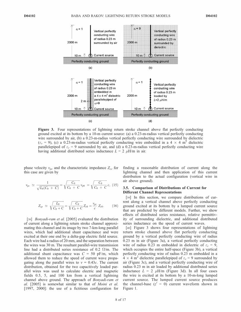
[39] In this section, we compare distributions of cur-rent along a vertical channel above perfectly conductingground excited at its bottom by a lumped current sourcethat are predicted by different models. Further, we showeffects of distributed series resistance, relative permittiv-ity of surrounding dielectric, and additional distributedseries inductance on the speed of current waves.[40] Figure 3 shows four representations of lightning
return stroke channel above flat perfectly conductingground by a vertical perfectly conducting wire of radius0.23 m in air (Figure 3a), a vertical perfectly conductingwire of radius 0.23 m embedded in dielectric of er = 9,which occupies the entire half-space (Figure 3b), a verticalperfectly conducting wire of radius 0.23 m embedded in a4 � 4 m2 dielectric parallelepiped of er = 9 surrounded byair (Figure 3c), and a vertical perfectly conducting wire ofradius 0.23 m in air loaded by additional distributed seriesinductance L = 2 mH/m (Figure 3d). In all four casesthe wire is excited at its bottom by a 10-m-long lumpedcurrent source. The lumped current source producesthe channel-base (z0 = 0) current waveform shown inFigure 1.
Figure 3. Four representations of lightning return stroke channel above flat perfectly conductingground excited at its bottom by a 10-m current source: (a) a 0.23-m-radius vertical perfectly conductingwire surrounded by air, (b) a 0.23-m-radius vertical perfectly conducting wire surrounded by dielectric(er = 9), (c) a 0.23-m-radius vertical perfectly conducting wire embedded in a 4 � 4 m2 dielectricparallelepiped of er = 9 surrounded by air, and (d) a 0.23-m-radius vertical perfectly conducting wirehaving additional distributed series inductance L = 2 mH/m in air.
D04102 BABA AND RAKOV: LIGHTNING RETURN STROKE MODELS
8 of 17
D04102
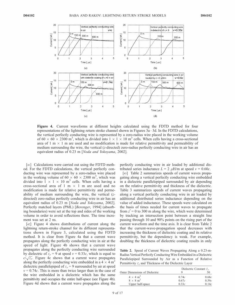
[41] Calculations were carried out using the FDTD meth-od. For the FDTD calculations, the vertical perfectly con-ducting wire was represented by a zero-radius wire placedin the working volume of 60 � 60 � 2300 m3, which wasdivided into 1 � 1 � 10 m3 cells. When cells having across-sectional area of 1 m � 1 m are used and nomodification is made for relative permittivity and perme-ability of medium surrounding the wire, the vertical (z-directed) zero-radius perfectly conducting wire in air has anequivalent radius of 0.23 m [Noda and Yokoyama, 2002].Perfectly matched layers (PML) [Berenger, 1994] (absorb-ing boundaries) were set at the top and sides of the workingvolume in order to avoid reflections there. The time incre-ment was set at 2 ns.[42] Figure 4 shows distributions of current along the
lightning return-stroke channel for its different representa-tions shown in Figure 3, calculated using the FDTDmethod. It is clear from Figure 4a that a current wavepropagates along the perfectly conducting wire in air at thespeed of light. Figure 4b shows that a current wavepropagates along the perfectly conducting wire surroundedby dielectric of er = 9 at speed v = 0.33c, which is equal toc/
ffiffiffiffier
p. Figure 4c shows that a current wave propagates
along the perfectly conducting wire embedded in a 4 � 4 m2
dielectric parallelepiped of er = 9 surrounded by air at speedv = 0.74c. This is more than twice larger than in the case ofthe wire embedded in a dielectric which has the samepermittivity and occupies the entire half-space (see Figure 4b).Figure 4d shows that a current wave propagates along the
perfectly conducting wire in air loaded by additional dis-tributed series inductance L = 2 mH/m at speed v = 0.60c.[43] Table 2 summarizes speeds of current waves propa-
gating along a vertical perfectly conducting wire embeddedin a dielectric parallelepiped surrounded by air dependingon the relative permittivity and thickness of the dielectric.Table 3 summarizes speeds of current waves propagatingalong a vertical perfectly conducting wire in air loaded byadditional distributed series inductance depending on thevalue of added inductance. These speeds were calculated onthe basis of times needed for current waves to propagatefrom z0 = 0 to 300 m along the wire, which were determinedby tracking an intersection point between a straight linepassing through 10 and 90% points on the rising part of thecurrent waveform and the time axis. It is clear from Table 2that the current-wave-propagation speed decreases withincreasing the thickness of dielectric coating and its relativepermittivity, but the dependency is weak. For example,doubling the thickness of dielectric coating results in only
Figure 4. Current waveforms at different heights calculated using the FDTD method for fourrepresentations of the lightning return stroke channel shown in Figures 3a–3d. In the FDTD calculations,the vertical perfectly conducting wire is represented by a zero-radius wire placed in the working volumeof 60 � 60 � 2300 m3, which is divided into 1 � 1 � 10 m3 cells. When cells having a cross-sectionalarea of 1 m � 1 m are used and no modification is made for relative permittivity and permeability ofmedium surrounding the wire, the vertical (z-directed) zero-radius perfectly conducting wire in air has anequivalent radius of 0.23 m [Noda and Yokoyama, 2002].
Table 2. Speed of Current Waves Propagating Along a 0.23-m-
Radius Vertical Perfectly ConductingWire Embedded in aDielectric
Parallelepiped Surrounded by Air as a Function of Relative
Permittivity er and Thickness of the Dielectric Layer
Outer Dimensions of DielectricDielectric Constant er9 50
4 � 4 m2 0.74c 0.68c8 � 8 m2 0.67c 0.59cUpper half-space 0.33c 0.14c
D04102 BABA AND RAKOV: LIGHTNING RETURN STROKE MODELS
9 of 17
D04102
about 10% decrease in the current-wave-propagation speed,and an increase in the relative permittivity from er = 9 to 50also results in only about 10% decrease. In order to reducethe speed of current wave propagating along a verticalconducting wire having a dielectric coating, which issurrounded by air, to a value less than the speed of light,the relative permittivity of the dielectric coating needs to bemuch higher than the value that follows from c/
ffiffiffiffier
p. It is
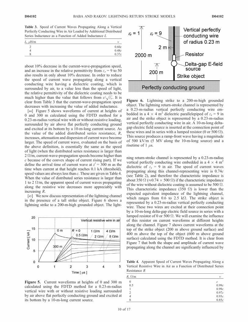
clear from Table 3 that the current-wave-propagation speeddecreases with increasing the value of added inductance.[44] Figure 5 shows waveforms of current at heights of
0 and 300 m calculated using the FDTD method for a0.23-m-radius vertical wire with or without resistive loading,surrounded by air above flat perfectly conducting groundand excited at its bottom by a 10-m-long current source. Asthe value of the added distributed series resistance, R,increases, attenuation and dispersion of current wave becomelarger. The speed of current wave, evaluated on the basis ofthe above definition, is essentially the same as the speedof light (when the distributed series resistance is larger than2W/m, current-wave-propagation speeds become higher thanc because of the convex shape of current rising part). If wedefine the arrival time of current wave at z0 = 300 m as thetime when current at that height reaches 0.1 kA (threshold),speed values are always less than c. These are given in Table 4.When the value of distributed series resistance is larger than1 to 2 W/m, the apparent speed of current waves propagatingalong the resistive wire decreases more appreciably withincreasing R.[45] We now discuss representation of the lightning channel
in the presence of a tall strike object. Figure 6 shows alightning strike to a 200-m-high grounded object. The light-
ning return-stroke channel is represented by a 0.23-m-radiusvertical perfectly conducting wire embedded in a 4 � 4 m2
dielectric of er = 9 in air. The speed of current wavespropagating along this channel-representing wire is 0.74c(see Table 2), and therefore the characteristic impedance isabout 350 W (�0.74� 500 W) if the characteristic impedanceof the wire without dielectric coating is assumed to be 500 W.This characteristic impedance (350 W) is lower than theexpected equivalent impedance of the lightning channel,which ranges from 0.6 to 2.5 kW. The strike object isrepresented by a 0.23-m-radius vertical perfectly conductingwire. These two wires are excited at their connection pointby a 10-m-long delta-gap electric field source in series with alumped resistor of 0 or 500 W. We will examine the influenceof this resistor on current waveforms at different heightsalong the channel. Figure 7 shows current waveforms at thetop of the strike object (200 m above ground surface) and400 m above the top of the object (600 m above groundsurface) calculated using the FDTD method. It is clear fromFigure 7 that both the shape and amplitude of current wavepropagating along the channel are significantly influenced by
Table 3. Speed of Current Waves Propagating Along a Vertical
Perfectly Conducting Wire in Air Loaded by Additional Distributed
Series Inductance as a Function of Added Inductance L
L, mH/m v
2 0.60c4 0.48c8 0.37c
Figure 5. Current waveforms at heights of 0 and 300 mcalculated using the FDTD method for a 0.23-m-radiusvertical wire with or without resistive loading surroundedby air above flat perfectly conducting ground and excited atits bottom by a 10-m-long current source.
Figure 6. Lightning strike to a 200-m-high groundedobject. The lightning return-stroke channel is represented bya 0.23-m-radius vertical perfectly conducting wire em-bedded in a 4 � 4 m2 dielectric parallelepiped of er = 9 inair and the strike object is represented by a 0.23-m-radiusvertical perfectly conducting wire in air. A 10-m-long delta-gap electric field source is inserted at the connection point ofthese wires and in series with a lumped resistor (0 or 500 W).This source produces a ramp-front wave having a magnitudeof 500 kV/m (5 MV along the 10-m-long source) and arisetime of 1 ms.
Table 4. Apparent Speed of Current Waves Propagating Along a
Vertical Resistive Wire in Air as a Function of Distributed Series
Resistance R
R, W/m v
0 c0.5 0.99c1 0.99c2 0.97c4 0.93c8 0.85c
D04102 BABA AND RAKOV: LIGHTNING RETURN STROKE MODELS
10 of 17
D04102
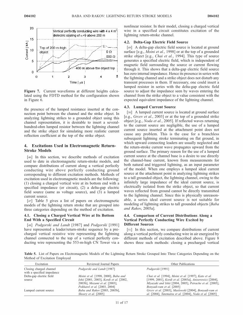
the presence of the lumped resistance inserted at the con-nection point between the channel and the strike object. Inanalyzing lightning strikes to a grounded object using thischannel representation, it is desirable to insert a several-hundred-ohm lumped resistor between the lightning channeland the strike object for simulating more realistic currentreflection coefficient at the top of the strike object.
4. Excitations Used in Electromagnetic Return-Stroke Models
[46] In this section, we describe methods of excitationused to date in electromagnetic return-stroke models, andcompare distributions of current along a vertical perfectlyconducting wire above perfectly conducting groundcorresponding to different excitation methods. Methods ofexcitation used in electromagnetic models are the following:(1) closing a charged vertical wire at its bottom end with aspecified impedance (or circuit), (2) a delta-gap electricfield source (same as voltage source), and (3) a lumpedcurrent source.[47] Table 5 gives a list of papers on electromagnetic
models of the lightning return stroke that are grouped intothree categories depending on the method of excitation.
4.1. Closing a Charged Vertical Wire at Its BottomEnd With a Specified Circuit
[48] Podgorski and Landt [1987] and Podgorski [1991]have represented a leader/return-stroke sequence by a pre-charged vertical resistive wire representing the lightningchannel connected to the top of a vertical perfectly con-ducting wire representing the 553-m-high CN Tower via a
nonlinear resistor. In their model, closing a charged verticalwire in a specified circuit constitutes excitation of thelightning return-stroke channel.
4.2. Delta-Gap Electric Field Source
[49] A delta-gap electric field source is located at groundsurface [e.g., Moini et al., 1998] or at the top of a groundedstrike object [e.g., Chai et al., 1994]. This type of sourcegenerates a specified electric field, which is independent ofmagnetic field surrounding the source or current flowingthrough it. This shows that a delta-gap electric field sourcehas zero internal impedance. Hence its presence in series withthe lightning channel and a strike object does not disturb anytransient processes in them. If necessary, one could insert alumped resistor in series with the delta-gap electric fieldsource to adjust the impedance seen by waves entering thechannel from the strike object to a value consistent with theexpected equivalent impedance of the lightning channel.
4.3. Lumped Current Source
[50] A lumped current source is located at ground surface[e.g., Grcev et al., 2003] or at the top of a grounded strikeobject [e.g., Noda et al., 2005]. If reflected waves returningto the current source are negligible, the use of a lumpedcurrent source inserted at the attachment point does notcause any problem. This is the case for a branchlesssubsequent lightning stroke terminating on flat ground, inwhich upward connecting leaders are usually neglected andthe return-stroke current wave propagates upward from theground surface. The primary reason for the use of a lumpedcurrent source at the channel base is a desire to use directlythe channel-base current, known from measurements forboth natural and triggered lightning, as an input parameterof the model. When one employs a lumped ideal currentsource at the attachment point in analyzing lightning strikesto a tall grounded object, the lightning channel, owing to theinfinitely large impedance of the ideal current source, iselectrically isolated from the strike object, so that currentwaves reflected from ground cannot be directly transmittedto the lightning channel. Since this is physically unreason-able, a series ideal current source is not suitable formodeling of lightning strikes to tall grounded objects [Babaand Rakov, 2005a].
4.4. Comparison of Current Distributions Along aVertical Perfectly Conducting Wire Excited byDifferent Sources
[51] In this section, we compare distributions of currentalong a vertical perfectly conducting wire in air energized bydifferent methods of excitation described above. Figure 8shows three such methods: closing a precharged vertical
Figure 7. Current waveforms at different heights calcu-lated using the FDTD method for the configuration shownin Figure 6.
Table 5. List of Papers on Electromagnetic Models of the Lightning Return Stroke Grouped Into Three Categories Depending on the
Method of Excitation Employed
Excitation Reviewed Journal Papers Other Publications
Closing charged channelwith a specified impedance
Podgorski and Landt [1987] Podgorski [1991]
Delta-gap electric fieldsource
Moini et al. [1998, 2000], Baba andIshii [2001, 2003], Kordi et al. [2002,2003b], Mozumi et al. [2003],Pokharel et al. [2003, 2004]
Chai et al. [1994], Moini et al. [1997], Kato et al.[1999, 2001], Kordi et al. [2003a], Aniserowicz [2004],Miyazaki and Ishii [2004, 2005], Petrache et al. [2005],Bonyadi-ram et al. [2005]
Lumped current source Baba and Rakov [2003, 2005b],Shoory et al. [2005]
Grcev et al. [2003], Maslowski [2004], Bonyadi-ram etal. [2004], Tatematsu et al. [2004], Noda et al. [2005]
D04102 BABA AND RAKOV: LIGHTNING RETURN STROKE MODELS
11 of 17
D04102
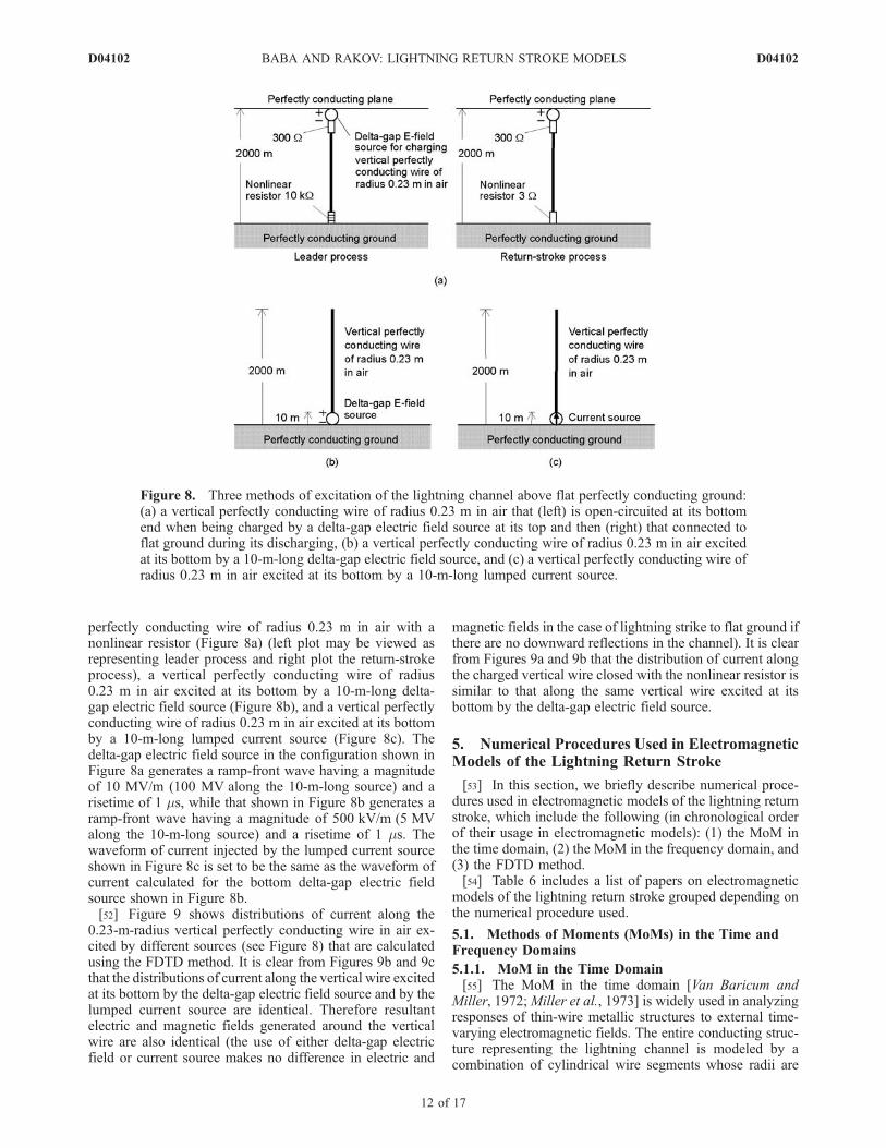
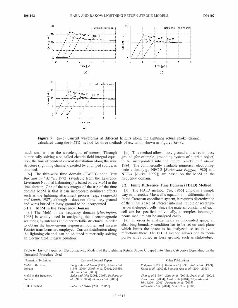
perfectly conducting wire of radius 0.23 m in air with anonlinear resistor (Figure 8a) (left plot may be viewed asrepresenting leader process and right plot the return-strokeprocess), a vertical perfectly conducting wire of radius0.23 m in air excited at its bottom by a 10-m-long delta-gap electric field source (Figure 8b), and a vertical perfectlyconducting wire of radius 0.23 m in air excited at its bottomby a 10-m-long lumped current source (Figure 8c). Thedelta-gap electric field source in the configuration shown inFigure 8a generates a ramp-front wave having a magnitudeof 10 MV/m (100 MV along the 10-m-long source) and arisetime of 1 ms, while that shown in Figure 8b generates aramp-front wave having a magnitude of 500 kV/m (5 MValong the 10-m-long source) and a risetime of 1 ms. Thewaveform of current injected by the lumped current sourceshown in Figure 8c is set to be the same as the waveform ofcurrent calculated for the bottom delta-gap electric fieldsource shown in Figure 8b.[52] Figure 9 shows distributions of current along the
0.23-m-radius vertical perfectly conducting wire in air ex-cited by different sources (see Figure 8) that are calculatedusing the FDTD method. It is clear from Figures 9b and 9cthat the distributions of current along the vertical wire excitedat its bottom by the delta-gap electric field source and by thelumped current source are identical. Therefore resultantelectric and magnetic fields generated around the verticalwire are also identical (the use of either delta-gap electricfield or current source makes no difference in electric and
magnetic fields in the case of lightning strike to flat ground ifthere are no downward reflections in the channel). It is clearfrom Figures 9a and 9b that the distribution of current alongthe charged vertical wire closed with the nonlinear resistor issimilar to that along the same vertical wire excited at itsbottom by the delta-gap electric field source.
5. Numerical Procedures Used in ElectromagneticModels of the Lightning Return Stroke
[53] In this section, we briefly describe numerical proce-dures used in electromagnetic models of the lightning returnstroke, which include the following (in chronological orderof their usage in electromagnetic models): (1) the MoM inthe time domain, (2) the MoM in the frequency domain, and(3) the FDTD method.[54] Table 6 includes a list of papers on electromagnetic
models of the lightning return stroke grouped depending onthe numerical procedure used.
5.1. Methods of Moments (MoMs) in the Time andFrequency Domains
5.1.1. MoM in the Time Domain[55] The MoM in the time domain [Van Baricum and
Miller, 1972;Miller et al., 1973] is widely used in analyzingresponses of thin-wire metallic structures to external time-varying electromagnetic fields. The entire conducting struc-ture representing the lightning channel is modeled by acombination of cylindrical wire segments whose radii are
Figure 8. Three methods of excitation of the lightning channel above flat perfectly conducting ground:(a) a vertical perfectly conducting wire of radius 0.23 m in air that (left) is open-circuited at its bottomend when being charged by a delta-gap electric field source at its top and then (right) that connected toflat ground during its discharging, (b) a vertical perfectly conducting wire of radius 0.23 m in air excitedat its bottom by a 10-m-long delta-gap electric field source, and (c) a vertical perfectly conducting wire ofradius 0.23 m in air excited at its bottom by a 10-m-long lumped current source.
D04102 BABA AND RAKOV: LIGHTNING RETURN STROKE MODELS
12 of 17
D04102
much smaller than the wavelengths of interest. Throughnumerically solving a so-called electric field integral equa-tion, the time-dependent current distribution along the wirestructure (lightning channel), excited by a lumped source, isobtained.[56] The thin-wire time domain (TWTD) code [Van
Baricum and Miller, 1972] (available from the LawrenceLivermore National Laboratory) is based on the MoM in thetime domain. One of the advantages of the use of the timedomain MoM is that it can incorporate nonlinear effectssuch as the lightning attachment process [e.g., Podgorskiand Landt, 1987], although it does not allow lossy groundand wires buried in lossy ground to be incorporated.5.1.2. MoM in the Frequency Domain[57] The MoM in the frequency domain [Harrington,
1968] is widely used in analyzing the electromagneticscattering by antennas and other metallic structures. In orderto obtain the time-varying responses, Fourier and inverseFourier transforms are employed. Current distribution alongthe lightning channel can be obtained numerically solvingan electric field integral equation.
[58] This method allows lossy ground and wires in lossyground (for example, grounding system of a strike object)to be incorporated into the model [Burke and Miller,1984]. The commercially available numerical electromag-netic codes (e.g., NEC-2 [Burke and Poggio, 1980] andNEC-4 [Burke, 1992]) are based on the MoM in thefrequency domain.
5.2. Finite Difference Time Domain (FDTD) Method
[59] The FDTD method [Yee, 1966] employs a simpleway to discretize Maxwell’s equations in differential form.In the Cartesian coordinate system, it requires discretizationof the entire space of interest into small cubic or rectangu-lar-parallelepiped cells. Since the material constants of eachcell can be specified individually, a complex inhomoge-neous medium can be analyzed easily.[60] In order to analyze fields in unbounded space, an
absorbing boundary condition has to be set on each planewhich limits the space to be analyzed, so as to avoidreflections there. The FDTD method allows one to incor-porate wires buried in lossy ground, such as strike-object
Figure 9. (a–c) Current waveforms at different heights along the lightning return stroke channelcalculated using the FDTD method for three methods of excitation shown in Figures 8a–8c.
Table 6. List of Papers on Electromagnetic Models of the Lightning Return Stroke Grouped Into Three Categories Depending on the
Numerical Procedure Used
Numerical Technique Reviewed Journal Papers Other Publications
MoM in the timedomain
Podgorski and Landt [1987], Moini et al.[1998, 2000], Kordi et al. [2002, 2003b],Mozumi et al. [2003]
Podgorski [1991], Moini et al. [1997], Kato et al. [1999],Kordi et al. [2003a], Bonyadi-ram et al. [2004, 2005]
MoM in the frequencydomain
Baba and Ishii [2001, 2003], Pokharel etal. [2003, 2004], Shoory et al. [2005]
Chai et al. [1994], Kato et al. [2001], Grcev et al. [2003],Aniserowicz [2004], Maslowski [2004], Miyazaki andIshii [2004, 2005], Petrache et al. [2005]
FDTD method Baba and Rakov [2003, 2005b] Tatematsu et al. [2004], Noda et al. [2005]
D04102 BABA AND RAKOV: LIGHTNING RETURN STROKE MODELS
13 of 17
D04102
grounding electrodes [Noda et al., 2005], as well as non-linear effects.
5.3. Comparison of Current Distributions Along aVertical Perfectly Conducting Wire Calculated UsingDifferent Numerical Procedures With Those Predictedby Chen’s Analytical Equation
[61] In this section, we compare distributions of currentalong a channel-representing vertical wire, calculated usingMoMs in the time and frequency domains and the FDTD
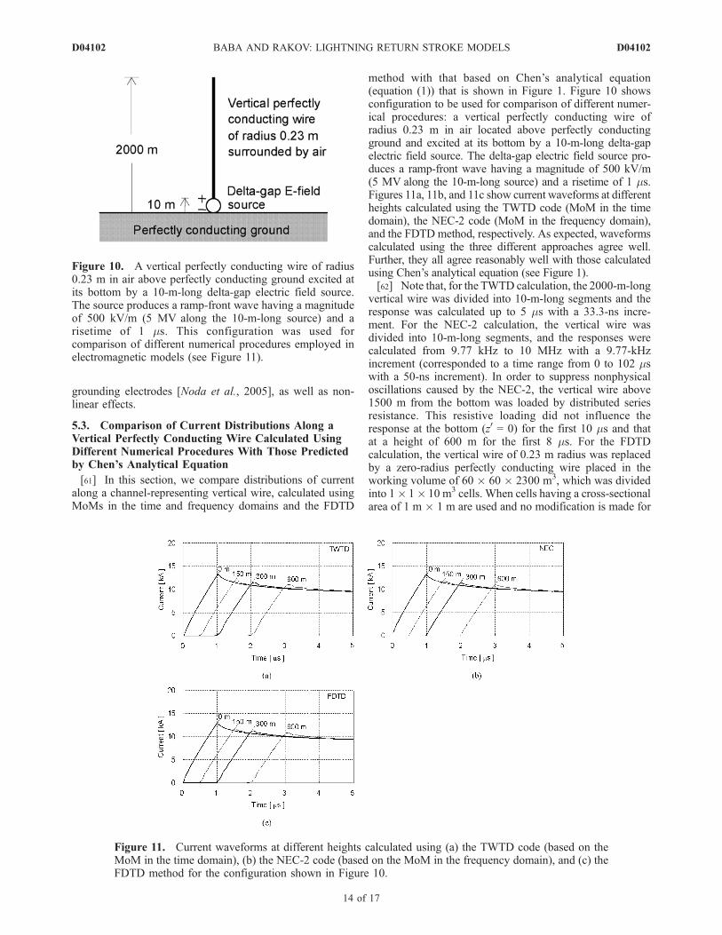
method with that based on Chen’s analytical equation(equation (1)) that is shown in Figure 1. Figure 10 showsconfiguration to be used for comparison of different numer-ical procedures: a vertical perfectly conducting wire ofradius 0.23 m in air located above perfectly conductingground and excited at its bottom by a 10-m-long delta-gapelectric field source. The delta-gap electric field source pro-duces a ramp-front wave having a magnitude of 500 kV/m(5 MV along the 10-m-long source) and a risetime of 1 ms.Figures 11a, 11b, and 11c show current waveforms at differentheights calculated using the TWTD code (MoM in the timedomain), the NEC-2 code (MoM in the frequency domain),and the FDTD method, respectively. As expected, waveformscalculated using the three different approaches agree well.Further, they all agree reasonably well with those calculatedusing Chen’s analytical equation (see Figure 1).[62] Note that, for the TWTD calculation, the 2000-m-long
vertical wire was divided into 10-m-long segments and theresponse was calculated up to 5 ms with a 33.3-ns incre-ment. For the NEC-2 calculation, the vertical wire wasdivided into 10-m-long segments, and the responses werecalculated from 9.77 kHz to 10 MHz with a 9.77-kHzincrement (corresponded to a time range from 0 to 102 mswith a 50-ns increment). In order to suppress nonphysicaloscillations caused by the NEC-2, the vertical wire above1500 m from the bottom was loaded by distributed seriesresistance. This resistive loading did not influence theresponse at the bottom (z0 = 0) for the first 10 ms and thatat a height of 600 m for the first 8 ms. For the FDTDcalculation, the vertical wire of 0.23 m radius was replacedby a zero-radius perfectly conducting wire placed in theworking volume of 60 � 60 � 2300 m3, which was dividedinto 1� 1� 10 m3 cells. When cells having a cross-sectionalarea of 1 m � 1 m are used and no modification is made for
Figure 10. A vertical perfectly conducting wire of radius0.23 m in air above perfectly conducting ground excited atits bottom by a 10-m-long delta-gap electric field source.The source produces a ramp-front wave having a magnitudeof 500 kV/m (5 MV along the 10-m-long source) and arisetime of 1 ms. This configuration was used forcomparison of different numerical procedures employed inelectromagnetic models (see Figure 11).
Figure 11. Current waveforms at different heights calculated using (a) the TWTD code (based on theMoM in the time domain), (b) the NEC-2 code (based on the MoM in the frequency domain), and (c) theFDTD method for the configuration shown in Figure 10.
D04102 BABA AND RAKOV: LIGHTNING RETURN STROKE MODELS
14 of 17
D04102
relative permittivity and permeability of medium surround-ing the wire, the vertical (z-directed) zero-radius perfectlyconducting wire in air has an equivalent radius of 0.23 m[Noda and Yokoyama, 2002]. Perfectly matched layers(PML) [Berenger, 1994] (absorbing boundaries) were setat the top and sides of the working volume in order to avoidreflections there. The time increment was set to 2 ns.
6. Summary
[63] We have classified electromagnetic return-strokemodels into four types depending on channel representationused to find the distribution of current along the channel: aperfectly conducting or resistive wire in air, a wire sur-rounded by dielectric (other than air), a wire loaded byadditional distributed series inductance in air, and two wireshaving additional distributed shunt capacitance in air. It isdesirable that models are capable of reproducing the fol-lowing two features of the lightning return stroke: typicalvalues of optically measured return-stroke wavefront speedranging from 0.33c to 0.67c, and the expected equivalentimpedance of the lightning return-stroke channel in therange from 0.6 to 2.5 kW. As a current wave propagatesupward along a vertical wire excited at its bottom by alumped source, it necessarily suffers attenuation even if thewire has no ohmic losses. Mechanism of this attenuation isrelated to the boundary condition for the tangential electricfield on the surface of the wire. The speed of current wavespropagating along a vertical perfectly conducting wire in airabove ground is essentially equal to the speed of light c,which is larger than typical values of measured return-strokewavefront speed. The characteristic impedance of the wireranges from 0.4 to 0.7 kW, which is somewhat lower thanthe expected equivalent impedance of the lightning return-stroke channel. When a vertical wire has distributed seriesresistance higher than 1 to 2 W/m, the apparent speed ofcurrent waves decreases appreciably with increasing thevalue of distributed resistance. The speed of current wavespropagating along a vertical perfectly conducting wiresurrounded by dielectric of relative permittivity er rangesfrom 0.67c to 0.33c when er ranges from 2.25 to 9. Thecorresponding characteristic impedance ranges from 0.13 to0.47 kW, which is lower than the expected equivalent
impedance of the lightning return-stroke channel. The speedof current waves propagating along a vertical perfectlyconducting wire loaded by additional distributed seriesinductance L ranges from 0.67c to 0.33c when L rangesfrom 2.6 to 17 mH/m. The corresponding characteristicimpedance ranges from 0.6 to 2.1 kW, which is similar tothe expected equivalent impedance of the lightning return-stroke channel.[64] Further, we have compared different methods of exci-
tation used to date in electromagnetic return-stroke models:closing a charged vertical wire at its bottom with a specifiedimpedance, a delta-gap electric field source, and a lumpedcurrent source. Distributions of current along the verticalperfectly conducting wire in air excited at its bottom by thedelta-gap electric field source and by the lumped currentsource are identical. Also, the distribution of current alongthe charged vertical perfectly conducting wire closed with thenonlinear resistor is similar to that along the same wire excitedat its bottom by the delta-gap electric field source.[65] Also, we have compared distributions of current
along a vertical perfectly conducting wire in air excited atits bottom by the delta-gap electric field source usingdifferent numerical procedures: MoMs in the time andfrequency domains, and the FDTD method. As expected,distributions of current along the vertical perfectly conduct-ing wire calculated using these three procedures agree well.They also agree reasonably well with those calculated usingChen’s analytical equation.[66] We have additionally found that the so-called hybrid
electromagnetic (HEM) model predicts current distributionalong the lightning channel that is consistent with thatobtained using electromagnetic models.
Appendix A: Comparison of CurrentDistribution Along a Vertical Wire CalculatedUsing an Electromagnetic Model With ThatPredicted by the Hybrid Electromagnetic (HEM)Model
[67] The hybrid electromagnetic (HEM) model developedby Visacro et al. [2002] has been applied to modelinglightning return strokes [e.g., Visacro and Silveira, 2004]
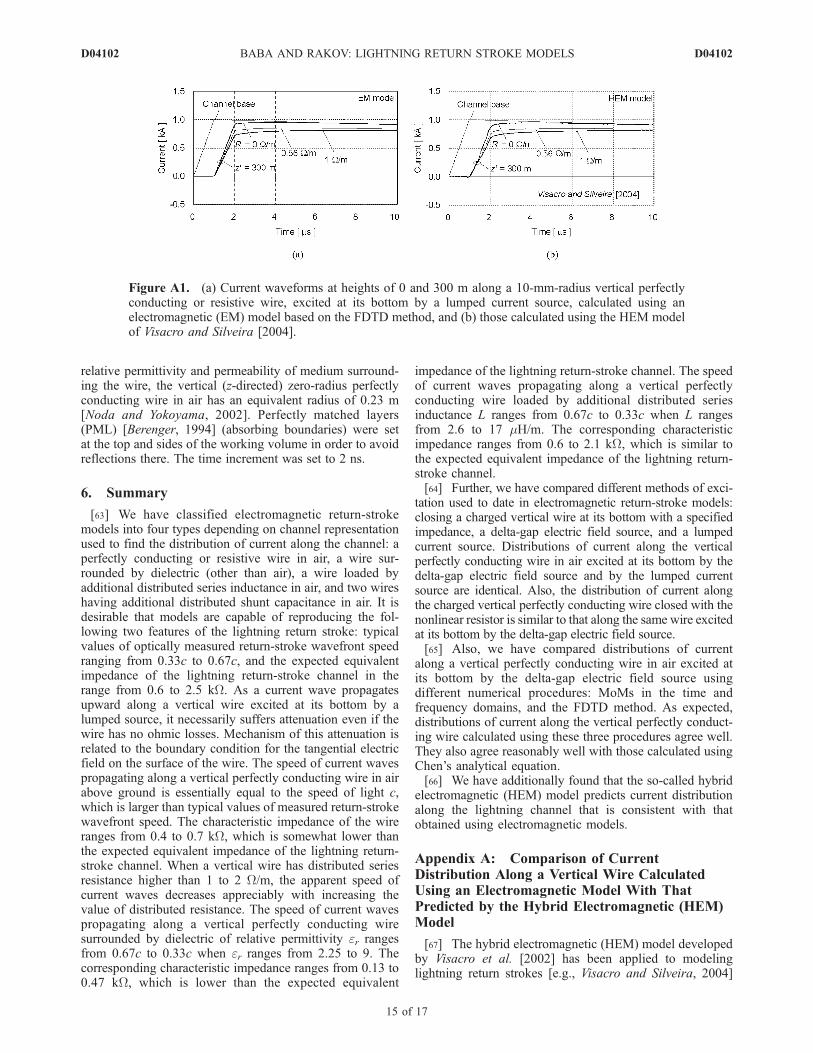
Figure A1. (a) Current waveforms at heights of 0 and 300 m along a 10-mm-radius vertical perfectlyconducting or resistive wire, excited at its bottom by a lumped current source, calculated using anelectromagnetic (EM) model based on the FDTD method, and (b) those calculated using the HEM modelof Visacro and Silveira [2004].
D04102 BABA AND RAKOV: LIGHTNING RETURN STROKE MODELS
15 of 17
D04102
and to analyzing the interaction of lightning with groundedobjects [Visacro and Soares, 2005]. In the HEM model,electric and magnetic fields are decoupled (solution forelectromagnetic fields is not a full-wave solution), but theelectromagnetic field structure is not TEM. In the following,we compare the current distribution along a vertical wireexcited at its bottom by a lumped current source aboveperfectly conducting ground calculated using the FDTDmethod with that predicted by the HEM model. The verticalwire has a radius of 10 mm and distributed series resistanceof 0, 0.56, or 1 W/m. The 10-mm-radius wire is representedin the FDTD procedure by a zero-radius wire (simulated byforcing the longitudinal components of electric field alongthe axis of the wire to zero) embedded in cells for which therelative permittivity is set to an artificially lower value andthe relative permeability to an artificially higher value[Noda and Yokoyama, 2002]. For our FDTD calculationswe set er and mr to 0.319 and 1/0.319, respectively. Thecurrent source generates a ramp wave having a magnitudeof 1 kA, a risetime of 1 ms, and a decay time to the half-peakvalue of 50 ms. Figure A1 shows current waveforms atheights 0 and 300 m along the vertical wire calculated usingthe electromagnetic model based on the FDTD method andthe HEM model. The HEM-calculated waveforms agreewell with the FDTD-calculated waveforms.
[68] Acknowledgments. This research was supported in part byDoshisha University and by NSF grant ATM-0346164. The authors wouldlike to acknowledge collaboration and useful discussions with (in alphabeticalorder) A. Ametani, K. Aniserowicz, S. Bonyadi-ram, V. Cooray, L. Grcev,A. M. Hussein, M. Ishii, W. Janischewskyj, S. Kato, B. Kordi, G. Maslowski,R. Moini, T. Mozumi, N. Nagaoka, R. K. Pokharel, F. Rachidi, G. Z.Rafi, M. Rubinstein, S. H. H. Sadeghi, V. O. Shostak, A. Shoory, F. Tesche,N. Theethayi, R. Thottappillil, M. A. Uman, and S. Visacro. The authorswould also like to thank two anonymous reviewers for their helpful commentsand suggestions.
ReferencesAniserowicz, K. (2004), A new algorithm for antenna theory modeling of alightning return stroke, paper presented at 27th International Conferenceon Lightning Protection, Soc. de l’Electr., de l’Electron., et des Technol.de l’Inf. et de la Commun., Avignon, France.
Baba, Y., and M. Ishii (2001), Numerical electromagnetic field analysis oflightning current in tall structures, IEEE Trans. Power Delivery, 16(2),324–328.
Baba, Y., and M. Ishii (2003), Characteristics of electromagneticreturn-stroke models, IEEE Trans. Electromagn. Compat., 45(1), 129–135.
Baba, Y., and V. A. Rakov (2003), On the transmission line model forlightning return stroke representation, Geophys. Res. Lett., 30(24),2294, doi:10.1029/2003GL018407.
Baba, Y., and V. A. Rakov (2005a), On the use of lumped sources inlightning return stroke models, J. Geophys. Res., 110, D03101,doi:10.1029/2004JD005202.
Baba, Y., and V. A. Rakov (2005b), On the mechanism of attenuation ofcurrent waves propagating along a vertical perfectly conducting wireabove ground: Application to lightning, IEEE Trans. Electromagn. Com-pat., 47(3), 521–532.
Baum, C. E., and L. Baker (1990) Analytic return-stroke transmission-linemodel, in Lightning Electromagnetics, pp. 17–40, Taylor and Francis,Philadelphia, Pa.
Berenger, J. P. (1994), A perfectly matched layer for the absorption ofelectromagnetic waves, J. Comput. Phys., 114, 185–200.
Bermudez, J. L., M. Rubinstein, F. Rachidi, F. Heidler, and M. Paolone(2003), Determination of reflection coefficients at the top and bottom ofelevated strike objects struck by lightning, J. Geophys. Res., 108(D14),4413, doi:10.1029/2002JD002973.
Bonyadi-ram, S., R. Moini, and S. H. H. Sadeghi (2004), Incorporation ofdistributed inductive loads in the antenna theory model of lightning returnstroke channel, paper presented at 27th International Conference onLightning Protection, Soc. de l’Electr., de l’Electron., et des Technol.de l’Inf. et de la Commun., Avignon, France.
Bonyadi-ram, S., R. Moini, S. H. H. Sadeghi, and V. A. Rakov (2005),Incorporation of distributed capacitive loads in the antenna theory modelof lightning return stroke, paper presented at 16th International ZurichSymposium and Technical Exhibition on Electromagnetic Compatibility,Swiss Fed. Inst. of Technol., Zurich, Switzerland.
Burke, G. J. (1992), Numerical Electromagnetic Code (NEC-4)—Methodof moments, UCRL-MA-109338, Lawrence Livermore Natl. Lab., Liver-more, Calif.
Burke, G. J., and E. K. Miller (1984), Modeling antennas near to andpenetrating a lossy interface, IEEE Trans. Antennas Propag., 32(10),1040–1049.
Burke, G. J., and A. J. Poggio (1980), Numerical Electromagnetic Code(NEC)—Method of moments, Tech. Doc. 116, Nav. Ocean Syst. Cent.,San Diego, Calif.
Chai, J. C., H. A. Heritage, and R. Briet (1994), Electromagnetic effects ofthe four-tower supported catenary wires array lightning protection sys-tem, paper presented at 16th International Aerospace and Ground Con-ference on Lightning and Static Electricity, Mannheim, Germany.
Chen, K. C. (1983), Transient response of an infinite cylindrical antenna,IEEE Trans. Antennas Propag., 31(1), 170–172.
Gomes, C., and V. Cooray (2000), Concepts of lightning return strokemodels, IEEE Trans. Electromagn. Compat., 42(1), 82–96.
Gorin, B. N., and A. V. Shkilev (1984), Measurements of lightning currentsat the Ostankino tower (in Russian), Electrichestrvo, 8, 64–65.
Goubau, G. (1950), Surface waves and their application to transmissionlines, J. Appl. Phys., 21, 1119–1128.
Grcev, L., F. Rachidi, and V. A. Rakov (2003), Comparison of electromag-netic models of lightning return strokes using current and voltage sources,paper presented at 12th International Conference on Atmospheric Elec-tricity, Int. Comm. on Atmos. Electr., Versailles, France.
Harrington, R. F. (1968), Field Computation by Moment Methods, Macmil-lan, New York.
Inan, U. S., and N. G. Lehtinen (2005), Production of terrestrial gamma-rayflashes by an electromagnetic pulse from a lightning return stroke, Geo-phys. Res. Lett., 32, L19818, doi:10.1029/2005GL023702.
Kato, S., T. Narita, T. Yamada, and E. Zaima (1999), Simulation of elec-tromagnetic field in lightning to tall tower, paper presented at 11th Inter-national Symposium on High Voltage Engineering, Inst. of Electr. Eng.,London, U. K.
Kato, S., T. Takinami, T. Hirai, and S. Okabe (2001), A study of lightningchannel model in numerical electromagnetic field computation (inJapanese), paper presented at 2001 IEEJ National Convention, Inst. ofElectr. Eng. of Jpn., Nagoya, Japan.
Kordi, B., R. Moini, and V. A. Rakov (2002), Comment on ‘‘Return stroketransmission line model for stroke speed near and equal that of light’’ byR. Thottappillil, J. Schoene, and M. A. Uman, Geophys. Res. Lett.,29(10), 1369, doi:10.1029/2001GL014602.
Kordi, B., R. Moini, and V. A. Rakov (2003a), Comparison of lightningreturn stroke electric fields predicted by the transmission line and antennatheory models, paper presented at 15th International Zurich Symposiumand Technical Exhibition on Electromagnetic Compatibility, Swiss Fed.Inst. of Technol., Zurich, Switzerland.
Kordi, B., R. Moini, W. Janischewskyj, A. M. Hussein, V. O. Shostak, andV. A. Rakov (2003b), Application of the antenna theory model to a talltower struck by lightning, J. Geophys. Res., 108(D17), 4542,doi:10.1029/2003JD003398.
Krider, E. P. (1994), On the peak electromagnetic fields radiated by light-ning return strokes toward the middle atmosphere, J. Atmos. Electr., 14,17–24.
Lin, Y. T., M. A. Uman, J. A. Tiller, R. D. Brantley, W. H. Beasley, E. P.Krider, and C. D. Weidman (1979), Characterization of lightning returnstroke electric and magnetic fields from simultaneous two-station mea-surements, J. Geophys. Res., 84(C10), 6307–6314.
Lu, G. (2006), Transient electric field at high altitudes due to lightning:Possible role of induction field in the formation of elves, J. Geophys.Res., 111, D02103, doi:10.1029/2005JD005781.
Maslowski, G. (2004), Some aspects of numerical modeling of lightningreturn stroke current based on antenna theory, paper presented at 27thInternational Conference on Lightning Protection, Soc. de l’Electr., del’Electron., et des Technol. de l’Inf. et de la Commun., Avignon, France.
Mattos, M. A. da F., and C. Christopoulos (1988), A nonlinear transmissionline model of the lightning return stroke, IEEE Trans. Electromagn.Compat., 30(3), 401–406.
Miller, E. K., A. J. Poggio, and G. J. Burke (1973), An integro-differentialequation technique for the time-domain analysis of thin wire structures,J. Comput. Phys., 12, 24–48.
Miyazaki, S., and M. Ishii (2004), Influence of elevated stricken object onlightning return-stroke current and associated fields, paper presented at27th International Conference on Lightning Protection, Soc. de l’Electr.,de l’Electron., et des Technol. de l’Inf. et de la Commun., Avignon, France.
D04102 BABA AND RAKOV: LIGHTNING RETURN STROKE MODELS
16 of 17
D04102
Miyazaki, S., and M. Ishii (2005), Lightning current distribution inside ofdirectly hit building, paper presented at 14th International Symposium onHigh Voltage Engineering, IEEE Dielectr. and Electr. Insulation Soc.,Beijing, China.
Moini, R., V. A. Rakov, M. A. Uman, and B. Kordi (1997), An antennatheory model for the lightning return stroke, paper presented at 12thInternational Zurich Symposium and Technical Exhibition on Electro-magnetic Compatibility, Swiss Fed. Inst. of Technol., Zurich, Switzerland.
Moini, R., B. Kordi, and M. Abedi (1998), Evaluation of LEMP effects oncomplex wire structures located above a perfectly conducting groundusing electric field integral equation in time domain, IEEE Trans.Electromagn. Compat., 40(2), 154–162.
Moini, R., B. Kordi, G. Z. Rafi, and V. A. Rakov (2000), A new lightningreturn stroke model based on antenna theory, J. Geophys. Res., 105(D24),29,693–29,702.
Mozumi, T., Y. Baba, M. Ishii, N. Nagaoka, and A. Ametani (2003),Numerical electromagnetic field analysis of archorn voltages during aback-flashover on a 500 kV twin-circuit line, IEEE Trans. Power Delivery,18(1), 207–213.
Noda, T., and S. Yokoyama (2002), Thin wire representation in finite dif-ference time domain surge simulation, IEEE Trans. Power Delivery,17(3), 840–847.
Noda, T., A. Tetematsu, and S. Yokoyama (2005), Improvements of anFDTD-based surge simulation code and its application to the lightningovervoltage calculation of a transmission tower, paper presented at Inter-national Conference on Power System Transients, Hydro-Quebec Trans-Energie, Montreal, Que., Canada.
Nucci, C. A., G. Diendorfer, M. A. Uman, F. Rachidi, M. Ianoz, andC. Mazzetti (1990), Lightning return stroke current models with specifiedchannel-base current: A review and comparison, J. Geophys. Res.,95(D12), 20,395–20,408.
Petrache, E., F. Rachidi, D. Pavanello, W. Janischewskyj, A. M. Hussein,M. Rubinstein, V. Shostak, W. A. Chisholm, and J. S. Chang (2005),Lightning strikes to elevated structures: influence of grounding condi-tions on currents and electromagnetic fields, paper presented at 2005IEEE International Symposium on Electromagnetic Compatibility, Inst.of Electr. and Electron. Eng., Chicago, Ill.
Podgorski, A. S. (1991), Three-dimensional time domain model of light-ning including corona effects, paper presented at 1991 InternationalAerospace and Ground Conference on Lightning and Static Electricity,NASA, Cocoa Beach, Fla.
Podgorski, A. S., and J. A. Landt (1987), Three dimensional time domainmodelling of lightning, IEEE Trans. Power Delivery, 2(3), 931–938.
Pokharel, R. K., M. Ishii, and Y. Baba (2003), Numerical electromagneticanalysis of lightning-induced voltage over ground of finite conductivity,IEEE Trans. Electromagn. Compat., 45(4), 651–666.
Pokharel, R. K., Y. Baba, and M. Ishii (2004), Numerical electromagneticfield analysis of transient induced voltages associated with lightning to atall structure, J. Electrostat., 60(2), 141–147.
Rachidi, F., V. A. Rakov, C. A. Nucci, and J. L. Bermudez (2002), Effect ofvertically extended strike object on the distribution of current along thelightning channel, J. Geophys. Res., 107(D23), 4699, doi:10.1029/2002JD002119.
Rakov, V. A. (1998), Some inferences on the propagation mechanisms ofdart leaders and return strokes, J. Geophys. Res., 103(D2), 1879–1887.
Rakov, V. A. (2004), Lightning return stroke speed: a review of experi-mental data, paper presented at 27th International Conference on Light-ning Protection, Soc. de l’Electr., de l’Electron., et des Technol. de l’Inf.et de la Commun., Avignon, France.
Rakov, V. A., and A. A. Dulzon (1987), Calculated electromagnetic fieldsof lightning return stroke (in Russian), Tekh. Electrodin., 1, 87–89.
Rakov, V. A., and W. G. Tuni (2003), Lightning electric field intensity athigh altitudes: Inferences for production of elves, J. Geophys. Res.,108(D20), 4639, doi:10.1029/2003JD003618.
Rakov, V. A., and M. A. Uman (1998), Review and evaluation of lightningreturn stroke models including some aspects of their application, IEEETrans. Electromagn. Compat., 40(4), 403–426.
Sadiku, M. N. O. (1994), Elements of Electromagnetics, Sounders Coll.,Orlando, Fla.
Shoory, A., R. Moini, S. H. H. Sadeghi, and V. A. Rakov (2005), Analysisof lightning-radiated electromagnetic fields in the vicinity of lossyground, IEEE Trans. Electromagn. Compat., 47(1), 131–145.
Tatematsu, A., T. Noda, and S. Yokoyama (2004), Simulation of lightning-induced voltages on a distribution line using the FDTD method, paperpresented at International Workshop on High Voltage Engineering, Inst.of Electr. Eng. of Jpn., Sapporo, Japan.
Thottappillil, R., and M. A. Uman (1993), Comparison of lightning return-stroke models, J. Geophys. Res., 98, 22,903–22,914.
Thottappillil, R., V. A. Rakov, andM.A.Uman (1997), Distribution of chargealong the lightning channel: Relation to remote electric andmagnetic fieldsand to return-stroke models, J. Geophys. Res., 102, 6987–7006.
Thottappillil, R., J. Schoene, and M. A. Uman (2001), Return stroke trans-mission line model for stroke speed near and equal that of light, Geophys.Res. Lett., 28(18), 3593–3596.
Uman, M. A., D. K. McLain, and E. P. Krider (1975), The electromagneticradiation from a finite antenna, Am. J. Phys., 43, 33–38.
Van Baricum, M., and E. K. Miller (1972), TWTD—A computer programfor time-domain analysis of thin-wire structures, UCRL-51-277, Lawr-ence Livermore Natl. Lab., Livermore, Calif.
Visacro, S., and F. H. Silveira (2004), Evaluation of current distributionalong the lightning discharge channel by a hybrid electromagnetic model,J. Electrostat., 60(2), 111–120.
Visacro, S., and A. Soares Jr. (2005), HEM: A model for simulation oflightning-related engineering problems, IEEE Trans. Power Delivery,20(2), 1206–1208.
Visacro, S. F., A. Soares Jr., and M. A. O. Schroeder (2002), An interactivecomputational code for simulation of transient behavior of electric systemcomponents for lightning currents, paper presented at 26th InternationalConference on Lightning Protection, Pol. Comm. on Lightning Prot.Cracow, Poland.
Wu, T. T. (1961), Transient response of a dipole antenna, J. Math. Phys., 2,892–894.
Yee, K. S. (1966), Numerical solution of initial boundary value problemsinvolving Maxwell’s equations in isotropic media, IEEE Trans. AntennasPropagat., 14(3), 302–307.
�����������������������Y. Baba, Department of Electrical Engineering, Doshisha University,
Kyoto 610–0321, Japan. ([email protected])V. A. Rakov, Department of Electrical and Computer Engineering,
University of Florida, Gainesville, FL 32611, USA. ([email protected])
D04102 BABA AND RAKOV: LIGHTNING RETURN STROKE MODELS
17 of 17
D04102
![136 IEEE TRANSACTIONS ON ELECTROMAGNETIC …...tial role of lightning in the Sago disaster [2]–[5]. The coupling mechanisms that may have brought lightning energy into the sealed](https://img.pdfslide.us/doc/110x75/5fd0f608f04cca5cd83f55f0/136-ieee-transactions-on-electromagnetic-tial-role-of-lightning-in-the-sago.jpg)


![Measured close lightning leader-step electric field ... et al [2011]a.pdfstepped‐leader steps from three negative lightning flashes at distances of tens to hundreds of meters. Electromagnetic](https://img.pdfslide.us/doc/110x75/5ffc6615b937847fb8527e0d/measured-close-lightning-leader-step-electric-field-et-al-2011apdf-steppedaleader.jpg)
![[1] Methods for Calculating Electromagnetic Fields From a Known Source Distribution Application to Lightning](https://img.pdfslide.us/doc/110x75/55cf9cdf550346d033ab5ab4/1-methods-for-calculating-electromagnetic-fields-from-a-known-source-distribution.jpg)


![Lightning Surge Analysis by EMTP and Mumerical Electromagnetic Analysis Method[1]](https://img.pdfslide.us/doc/110x75/547599dcb4af9fc30a8b5b28/lightning-surge-analysis-by-emtp-and-mumerical-electromagnetic-analysis-method1.jpg)