Embed Size (px)
Citation preview
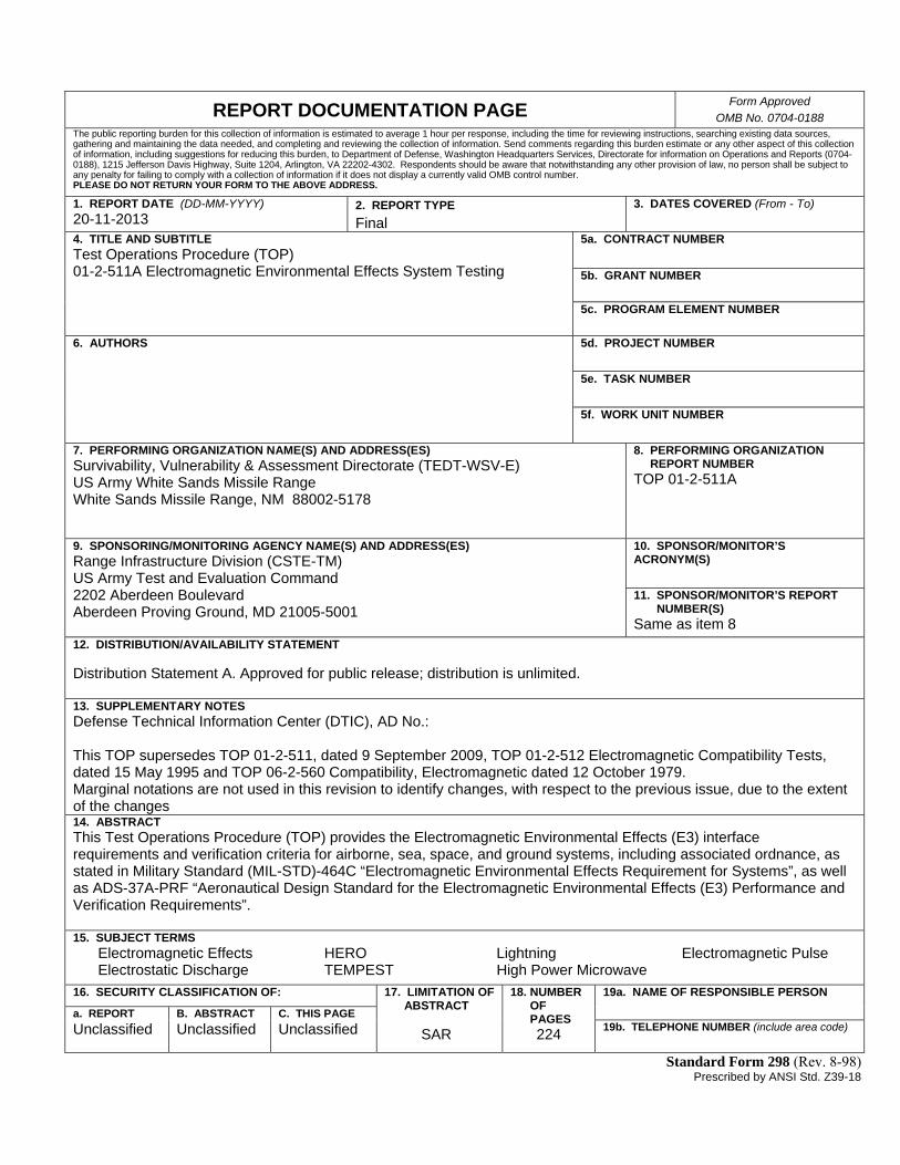
REPORT DOCUMENTATION PAGE Form Approved
OMB No. 0704-0188 The public reporting burden for this collection of information is estimated to average 1 hour per response, including the time for reviewing instructions, searching existing data sources, gathering and maintaining the data needed, and completing and reviewing the collection of information. Send comments regarding this burden estimate or any other aspect of this collection of information, including suggestions for reducing this burden, to Department of Defense, Washington Headquarters Services, Directorate for information on Operations and Reports (0704-0188), 1215 Jefferson Davis Highway, Suite 1204, Arlington, VA 22202-4302. Respondents should be aware that notwithstanding any other provision of law, no person shall be subject to any penalty for failing to comply with a collection of information if it does not display a currently valid OMB control number. PLEASE DO NOT RETURN YOUR FORM TO THE ABOVE ADDRESS.
1. REPORT DATE (DD-MM-YYYY) 20-11-2013
2. REPORT TYPE
Final 3. DATES COVERED (From - To)
4. TITLE AND SUBTITLE Test Operations Procedure (TOP) 01-2-511A Electromagnetic Environmental Effects System Testing
5a. CONTRACT NUMBER
5b. GRANT NUMBER
5c. PROGRAM ELEMENT NUMBER
6. AUTHORS
5d. PROJECT NUMBER
5e. TASK NUMBER
5f. WORK UNIT NUMBER
7. PERFORMING ORGANIZATION NAME(S) AND ADDRESS(ES) Survivability, Vulnerability & Assessment Directorate (TEDT-WSV-E) US Army White Sands Missile Range White Sands Missile Range, NM 88002-5178
8. PERFORMING ORGANIZATION REPORT NUMBER TOP 01-2-511A
9. SPONSORING/MONITORING AGENCY NAME(S) AND ADDRESS(ES) Range Infrastructure Division (CSTE-TM) US Army Test and Evaluation Command 2202 Aberdeen Boulevard Aberdeen Proving Ground, MD 21005-5001
10. SPONSOR/MONITOR’S ACRONYM(S)
11. SPONSOR/MONITOR’S REPORT NUMBER(S) Same as item 8
12. DISTRIBUTION/AVAILABILITY STATEMENT Distribution Statement A. Approved for public release; distribution is unlimited. 13. SUPPLEMENTARY NOTES Defense Technical Information Center (DTIC), AD No.: This TOP supersedes TOP 01-2-511, dated 9 September 2009, TOP 01-2-512 Electromagnetic Compatibility Tests, dated 15 May 1995 and TOP 06-2-560 Compatibility, Electromagnetic dated 12 October 1979. Marginal notations are not used in this revision to identify changes, with respect to the previous issue, due to the extent of the changes 14. ABSTRACT This Test Operations Procedure (TOP) provides the Electromagnetic Environmental Effects (E3) interface requirements and verification criteria for airborne, sea, space, and ground systems, including associated ordnance, as stated in Military Standard (MIL-STD)-464C “Electromagnetic Environmental Effects Requirement for Systems”, as well as ADS-37A-PRF “Aeronautical Design Standard for the Electromagnetic Environmental Effects (E3) Performance and Verification Requirements”. 15. SUBJECT TERMS Electromagnetic Effects HERO Lightning Electromagnetic Pulse Electrostatic Discharge TEMPEST High Power Microwave
16. SECURITY CLASSIFICATION OF: 17. LIMITATION OF ABSTRACT SAR
18. NUMBER OF PAGES
224
19a. NAME OF RESPONSIBLE PERSON
a. REPORT B. ABSTRACT C. THIS PAGE
Unclassified Unclassified Unclassified 19b. TELEPHONE NUMBER (include area code)
Standard Form 298 (Rev. 8-98) Prescribed by ANSI Std. Z39-18

(This page is intentionally blank.)
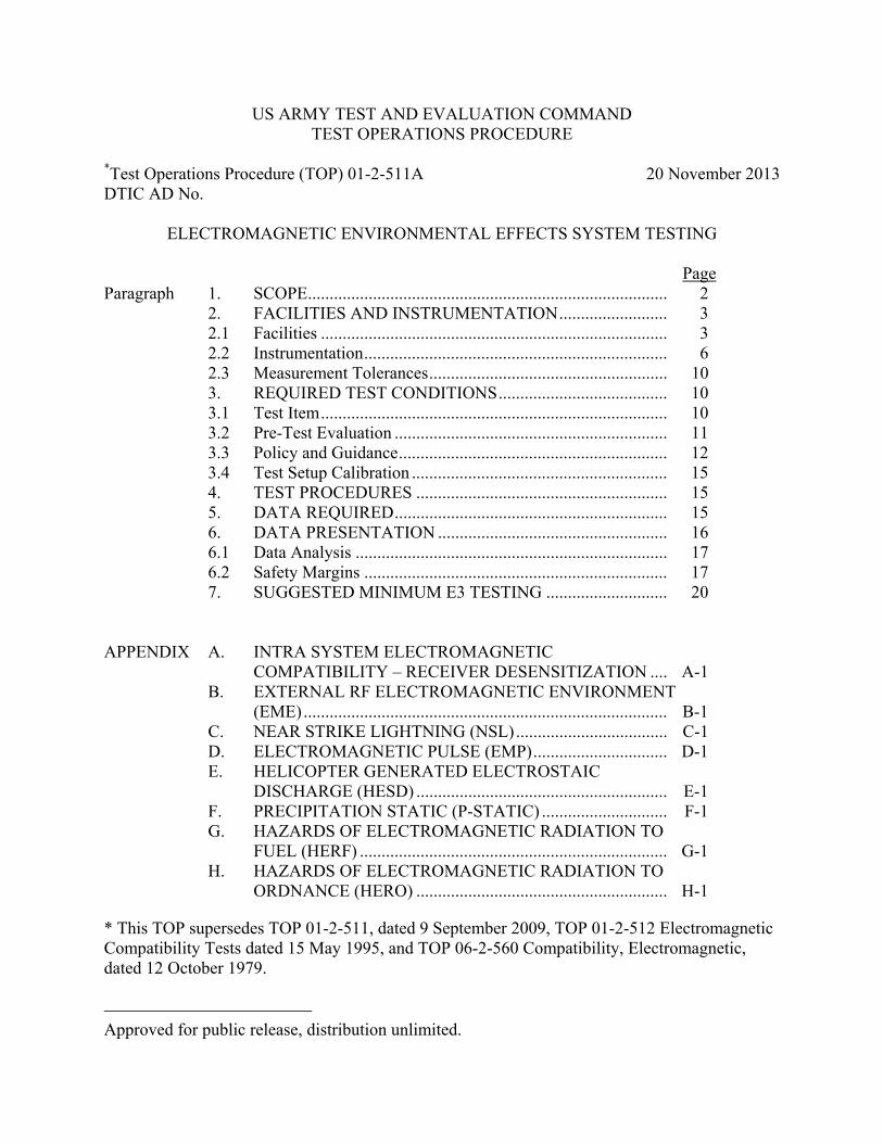
US ARMY TEST AND EVALUATION COMMAND TEST OPERATIONS PROCEDURE
*Test Operations Procedure (TOP) 01-2-511A 20 November 2013 DTIC AD No.
ELECTROMAGNETIC ENVIRONMENTAL EFFECTS SYSTEM TESTING Page Paragraph 1. SCOPE ................................................................................... 2 2. FACILITIES AND INSTRUMENTATION ......................... 3 2.1 Facilities ................................................................................ 3 2.2 Instrumentation ...................................................................... 6 2.3 Measurement Tolerances ....................................................... 10 3. REQUIRED TEST CONDITIONS ....................................... 10 3.1 Test Item ................................................................................ 10 3.2 Pre-Test Evaluation ............................................................... 11 3.3 Policy and Guidance .............................................................. 12 3.4 Test Setup Calibration ........................................................... 15 4. TEST PROCEDURES .......................................................... 15 5. DATA REQUIRED ............................................................... 15 6. DATA PRESENTATION ..................................................... 16 6.1 Data Analysis ........................................................................ 17 6.2 Safety Margins ...................................................................... 17 7. SUGGESTED MINIMUM E3 TESTING ............................ 20 APPENDIX A. INTRA SYSTEM ELECTROMAGNETIC COMPATIBILITY – RECEIVER DESENSITIZATION .... A-1 B. EXTERNAL RF ELECTROMAGNETIC ENVIRONMENT (EME) .................................................................................... B-1 C. NEAR STRIKE LIGHTNING (NSL) ................................... C-1 D. ELECTROMAGNETIC PULSE (EMP) ............................... D-1 E. HELICOPTER GENERATED ELECTROSTAIC DISCHARGE (HESD) .......................................................... E-1 F. PRECIPITATION STATIC (P-STATIC) ............................. F-1 G. HAZARDS OF ELECTROMAGNETIC RADIATION TO FUEL (HERF) ....................................................................... G-1 H. HAZARDS OF ELECTROMAGNETIC RADIATION TO ORDNANCE (HERO) .......................................................... H-1
* This TOP supersedes TOP 01-2-511, dated 9 September 2009, TOP 01-2-512 Electromagnetic Compatibility Tests dated 15 May 1995, and TOP 06-2-560 Compatibility, Electromagnetic, dated 12 October 1979.
Approved for public release, distribution unlimited.
TOP 01-2-511A 20 November 2013
2
I. TEMPEST ............................................................................. I-1 J. HIGH POWER MICROWAVE (HPM) ................................ J-1 K. INTRA SYSTEMS ELECTROMAGNETIC COMPATIBILITY, SYSTEM EMISSIONS, ELECTRIC FIELD, 10 kHz TO 40 GHz .................................................. K-1 L. INTRA SYSTEM ELECTROMAGNETIC COMPATIBILITY (EMC) SOURCE/VICTIM ................... L-1 M. PERSONNEL-BORNE ELECTROSTATIC DISCHARGE (PESD) ................................................................................... M-1 N. DIRECT STRIKE LIGHTNING (DSL) ............................... N-1 O. ABBREVIATIONS ............................................................... O-1 P. DEFINITIONS ...................................................................... P-1 Q. REFERENCES ...................................................................... Q-1 R. APPROVAL AUTHORITY .................................................. R-1 1. SCOPE. a. This Test Operations Procedure (TOP) provides the Electromagnetic (EM) Environmental Effects (E3) interface requirements and verification criteria for airborne, sea, space, and ground systems and platforms, including associated ordnance, as stated in Military Standard (MIL-STD)-464C1**, as well as Aeronautical Design Standard (ADS)-37A-PRF2, and Army-Tank Purchase Description (ATPD)-24073, or the latest version of the documents as applicable. This TOP does not provide interface requirements for subsystems and equipments operating in their defined EM Environment (EME); the control of EM Interference (EMI) characteristics of subsystems and equipments are covered in MIL-STD-461F4. Additionally, the suggested Minimum E3 Test Matrices have been developed by the US Army Test and Evaluation Command (ATEC) Test Centers and agreed upon by US Army Evaluation Center (AEC) and ATEC Higher command. They were developed to provide guidance to test program systems that are unable to determine the appropriate E3 tests that should be performed for their category of materiel, or will not meet safety and performance requirements based on the item specification or contract requirements. They were also developed to address the need for Army E3 Requirements Boards on smaller Soldier items and consistency for delivery of safe and functional items to the users. b. Environments. (1) This TOP is applicable for complete systems and platforms, both new and modified, and applies to engineering development, production and sustainment phases of the system (e.g., E3 life-cycle programs such as hardness and sustainment assurance, and surveillance testing). It should be noted that the Man/Soldier is a designated platform and should be addressed in that manner for safety and performance requirements. ** Superscript numbers correspond to Appendix Q, References.
TOP 01-2-511A 20 November 2013
3
(2) This TOP provides guidance for TEMPEST and test guidance for the addition of test procedures for implementing Electromagnetic Compatibility (EMC), Radiated Emissions (RE), receiver desensitization and electromagnetic noise on platforms, as well as the MIL-STD-2169B Notice 15 and High Power Microwave (HPM). A test procedure for Grounds and Bonds is not addressed since it is sufficiently discussed in MIL-STD-464C. For Shielding Effectiveness, reference American Society for Testing and Materials (ASTM) E1851-096 for test procedures. (3) This procedure applies to all categories of materiel containing electronic, electrical, electro-mechanical , and electro-optical components to include Electrically Initiated Devices (EID), which may be exposed to EMEs of high-intensity radiated electromagnetic fields in the EM spectrum between 10 kilo-Hertz (kHz) and 50 Giga-Hertz (GHz), Electrostatic Discharge (ESD), and Lightning Effects (LE). (4) Each system tested is to be monitored for degraded performance or operation. This can be defined as a malfunction, degradation, or as an unacceptable system response. Since each specific system responds differently to the same test environment, the results from the test can only be applied to the specific System or platform-Under-Test (SUT) configuration as tested. Therefore, testing for each system or platform configuration is required and warrants investigation. (5) The results of the tests conducted as outlined in this procedure will enable an evaluation to be made as to whether the system or platform tested meets the E3 requirements stated herein when subjected to the defined EMEs or conditions. In addition, these tests will enable a survivability assessment to the appropriate EMEs. Finally, these tests outlined in this TOP will enable an evaluation of whether the system or platform’s operational performance and E3 requirements are met throughout the rated life-cycle of the system or platform. (6) The test methods with specific details for each of the specific EMEs are contained in Appendices A through N. 2. FACILITIES AND INSTRUMENTATION. 2.1 Facilities. a. The facility must be capable of handling the test item in all of its configurations, from storage to pre-launch/operational and in-flight configurations as applicable; specifically stockpile to safe launch (for ordnance items) and in-flight (for guided ordnance). In-flight testing for guided/powered ordnance electronics should be accommodated. b. Fabrication facilities are required where instrumentation system(s) can be fabricated and installed in the test item in a manner that will not affect the electromagnetic radiation (EMR) susceptibility characteristics of the tactical configuration of the test item, and that will protect the instrumentation from EME effects. Instrumentation should consist of sensing elements, transmitting units, and associated interconnections. The equipment required in the fabrication facilities includes such items as machine tools, micromanipulators, sheet metal fabricating tools,
TOP 01-2-511A 20 November 2013
4
microscopes, Hazards of Electromagnetic Radiation to Ordnance (HERO) sensors, pneumatic switching, and those equipments associated with fiber optic technology. c. Test facility examples can be seen in the applicable appendix for each test method. d. Transmitters. (1) To validate a system/platform operational performance requirements are met, the SUT must be tested under laboratory conditions where the SUT and test environment are controlled and while being operated during illumination. System-level testing of large platforms such as aircraft, tanks, and ships, is usually done in an open area test site. Ideally, the entire system should be illuminated uniformly at full threat for the most credible demonstration of hardness. However, at many frequencies, test equipment does not exist to accomplish this task. Established test techniques are based on the size of the system compared to the wavelength of test frequency. At frequencies where the system is small compared to the wavelength of the illumination frequency [normally below 30 Megahertz (MHz)], it is necessary to illuminate the entire system uniformly at threat or to radiate the system such that appropriate electromagnetic stresses (radiated and conducted) are developed within the system. Producing these stresses is critical to properly testing the strength of the system since energy coupling is associated with cable lengths and conducted surfaces “effective antennas”. If these effective antennas are not properly stressed then realistic energy coupling will not occur and under testing will result. Where illumination of the entire system is not practical, various aspects of the system’s major physical dimensions should be illuminated uniformly at threat to couple the radiated field to the system structure in order to develop the correct stresses. At frequencies (normally above 400 MHz) where the size of the system is large compared to the wavelength, localized (spot) illumination is adequate to evaluate potential responses by illuminating specific apertures, cables and subsystems. At these higher frequencies (usually greater than 2 GHz), the so called “front door coupling” due to effective cable and body coupling “antennas” is replaced with “back door coupling” due to penetration. Thirty (30) to 400 MHz is a transition region from one concept to the other where either technique may be appropriate, dependent upon the system and the environment simulator. (2) For frequencies greater than 400 MHz, where the size of the test system is large compared to the wavelength, localized illuminations of specific apertures, cables and subsystems are permissible and recommended in evaluating potential responses. The tests system should be sufficiently illuminated to cover all aspects of the item (360 degree coverage). Suggested test frequencies are provided in the External RF EME Appendix. The emitters are radiated sequentially in both vertical and horizontal polarization. It usually is not practical to use circular and cross polarization. For an existing system which is undergoing re-testing after installation of a new subsystem less illumination positions may be acceptable. (3) For the situation where the external environment exceeds all available simulators or it is necessary to achieve whole system illumination, the method of bulk current testing should be used. The system can be illuminated from a distance to obtain near uniform illumination but at low levels. The induced current on the cable bundles from the uniform external field is measured. The induced current levels are then scaled to full current level based on the system’s
TOP 01-2-511A 20 November 2013
5
external environment. These extrapolated levels are compared to electromagnetic interference data on individual subsystems and equipment. If sufficient data are not available, cables can be driven at required levels on-board the system to evaluate the performance. The cable drive technique has been applied up to 400 MHz. (4) The transmitter should be swept with fixed frequency steps (stepped frequency methodology), or dwell at selected discrete frequencies. No fewer than 100 discrete frequencies should be utilized for HERO testing. It is suggested that the recommended HERO test frequencies of Table H-3, Appendix H are utilized, and be supplemented by those for External RF EME. For external RF EME testing it is suggested that no fewer than 350 discrete frequencies (utilizing the 100 suggested HERO frequencies) should be used. The list should include 275 average and 75 peak frequencies (where applicable for ordnance and mission essential systems). Inherent system frequencies should also be addressed for additional test frequency coverage. This will provide additional test frequencies in an effort to allow tailoring for a reasonable platform assessment. The need for testing below 1 MHz should be addressed with regard to magnetic fields and their affect on the system/platform under test, as well as to the ¼ wavelength of the total system/platform and the possibility of low frequency coupling. (5) Pulsed Peak Power Transmitters must be capable of developing frequencies and field intensities sufficient for illuminating with regard to the field intensities shown in Tables 1-9 of MIL-STD-464C. Peak pulsed power testing should be conducted on all electronic performance tests of platforms from 10 kHz–50 GHz (should use test frequencies of Table B-3 above 1 GHz) to ensure possible EME coupling to digital and switching circuits are adequately addressed. Peak pulsed power testing should also be conducted on subsystems in accordance with (IAW) HERO, aviation and/or shipboard operations requirements/guidance. (6) Sweep Transmitters. Sweep transmitters capable of generating a minimum of 10 percent of the criteria field intensities, shown in Tables 1 -9 of MIL-STD-464C, can be used for determining resonant frequencies of the test item for full threat testing by the test transmitter requirements described in paragraph 2.1.d(3) above. For EME testing, sweep generators capable of generating the criteria fields are required. The use of sweep transmitters for EMR testing is limited to systems whose configurations are not continually changing as a function of time (non-operational testing). Care should be taken to ensure that adequate sweep dwell times are considered when developing the system operation scenario for test assessment in order to capture potential anomalies within the actual test irradiation time. (7) Modulations including continuous wave (CW), as well as several variations of amplitude, frequency and pulse modulation (AM, FM, and PM); to include peak pulse are utilized in electromagnetic radiation testing to replicate those modulations encountered on the battlefield. It should be noted that AM, at a 1 kHz rate with a 50 percent duty cycle has been found to be a worst case modulation with regard to consistency and number of EME effects recorded. Should it be necessary, conducting a test with just AM at a 1 kHz rate with a 50 or 80 percent duty cycle can be utilized for most systems with confidence that the highest probability of EME induced effects will be captured. But, it is recommended that the modulations specified in Military Handbook (MIL-HDBK)-235/1C7 be utilized when practical based on the class of system under test. Refer to the handbook’s various appendices based on the specific class of system of interest; for example the ground systems appendix is MIL-HDBK-235/4C8. The

TOP 01-2-511A 20 November 2013
6
applicable appendix includes the modulations for that class of system. If one is conducting a tailored radiated susceptibility (RS)103 test with Open Air Test Site (OATS) procedures; be sure to include the PM modulation from MIL-STD-461. (8) Vertical and horizontal polarizations will be used with all EME frequencies above 30 MHz while only vertical is necessary below 30 MHz (special consideration will be taken as specified in MIL-HDBK-235/1C for the specific class of system). (9) Test Enclosure for Emissions Measurements. To prevent interaction between the SUT and the outside environment and to maintain laboratory conditions, shielded enclosures will usually be required for testing. These enclosures prevent external environment signals from contaminating emission measurements. The enclosures must be sufficiently large such that the SUT arrangement requirements and antenna positioning requirements of MIL-STD-461, as well as Appendices A and K for platform Intra system EMC and Appendix I for TEMPEST can be met. (10) Margins. Margins are critical in ensuring confidence in survivability of the system and for life-cycle management. Margins shall be provided based on system operational performance requirements, tolerances in system hardware, and uncertainties involved in verification of system-level design requirements. Safety critical and mission critical system functions shall have a margin of at least 6 decibel (dB). EIDs shall have a margin of at least 16.5 dB of maximum no-fire stimulus (MNFS) for safety consequences and 6 dB of MNFS for reliability consequences. Compliance shall be verified by test, analysis, or a combination thereof. Instrumentation installed in system components during testing for margins shall capture the maximum system response and shall not adversely affect the normal response characteristics of the component. When environment simulations below specified levels are used, instrumentation responses may be extrapolated to the full environment for components with linear responses (such as hot bridgewire EIDs). When the response is below instrumentation sensitivity, the instrumentation sensitivity shall be used as the basis for extrapolation. For components with non-linear responses (such as semiconductor bridge EIDs), no extrapolation is permitted. 2.2 Instrumentation. The instrumentation specifics will be presented in the applicable appendix for each test method. a. All Test equipment is calibrated regularly by calibration laboratories using procedures traceable to the National Institute of Standards and Technology (NIST). b. SUT instrumentation is permissible but it shall not influence test results. To minimize the possibility of instrumentation influencing test results or instrumentation susceptibility: (1) Use fiber-optic based instrumentation whenever possible. (2) Use twisted, shielded pair wiring when conductive leads are required.
TOP 01-2-511A 20 November 2013
7
(3) Instrumentation equipment and its leads should be buried inside the SUT with only the fiber optic leads exiting the SUT. c. Safety Testing. When the SUT contains ordnance or safety critical circuits / functions [e.g. EIDs (previously called Electro-explosive Devices (EEDs) the SUT ordnance and safety critical circuits / functions shall meet their safety requirements during and after exposure to the electromagnetic environment. The following methods are routinely utilized on Army Materiel; additional guidance is provided in MIL-HDBK-240A9. Joint Ordnance Test Procedure (JOTP)-06110 should be used for guidance in testing of joint munitions to HERO. A second JOTP is in process and should be used for guidance of joint ESD and Lightning testing. (1) There are two methods for testing EID safety which are described in detail in Section 3.6 (HERO Test Philosophy) of Army Technical Report TR-RD-TE-97-01, “Electromagnetic Environmental Effects Criteria and Guidelines for Electromagnetic Radiation Hazards (EMRH), EMRO, Lightning Effects, ESD, EMP, and EMI Testing of US Army Missile Systems”11. Electromagnetic Radiation Hazards (EMRH) is an antiquated term for HERO. The two methods for testing safety of SUT EIDs are: (a) Instrumented, inert SUT testing: The SUT EIDs are replaced by inert versions (explosive material removed for personnel and SUT safety) that are instrumented to measure the currents, voltages, power, or energy induced at the EIDs during safety testing. The measured results are compared to the EID Maximum No Fire (MNF) parameter after the MNF parameter is reduced by the EID required safety margin. Note that the measurement results should be extrapolated if the test facility cannot produce the required test levels (Refer to MIL-HDBK-240A). The methods of instrumentation are shown in Table 1. (b) Go/No-Go SUT testing: The SUT EIDs are left intact in the SUT and are not instrumented. A large number of SUTs with their live EIDs are tested to the test level in order to obtain a meaningful statistical sample. If a large number of SUTs or EIDs are not available, a smaller number of SUTs are subjected to test levels that are raised by the required EID safety margin. This test method requires that multiple EIDs be tested in order to obtain a meaningful statistical sample. The justification for the chosen sample size along with assumptions, the statistical test used, confidence levels (Army's risk), and power (Manufacturer's risk) should be addressed in the test plan. Testing repeated 10 times with no failures would give 80% confidence in the SUT having at least an 80% success rate (Clopper-Pearson method). Under the same method, a test with 22 repetitions and no failures would give a 90% confidence in the system having at least a 90% success rate. A higher number of repetitions should be used for airborne systems based on the additional risk in flight. Fresh EIDs should be used for each test run to provide some measure of confidence that the EIDs will remain safe. JOTP-061 should be used for guidance in testing of joint munitions to HERO. A second JOTP is in process and should be used for guidance of Joint ESD and Lightning testing.
TOP 01-2-511A 20 November 2013
8
TABLE 1. INSTRUMENTATION FOR E3 SAFETY METHODOLOGIES
TEST METHODOLOGY E3
ORDNANCE SAFETY TEST
INSTRUMENTATION COMMENTS
Instrumented EIDs -EIDs tested in SUT -CW E-field environment
HERO -Field probes to determine environment
-Thermal heating sensors (e.g., FISO or Metricor systems) used to detect bridgewire heating induced by field.
-Fiber optics from sensor to monitor
-Small sensors that easily fit in SUT.
-Can measure very small changes in temperature with appropriate sensitivity.
Instrumented EIDs -EIDs tested in SUT -Transient environment
PESD, HESD, NSL, DSL,
EMP
-Field probes & discharge current probe used to determine environment (Nanofast, EG&G, PRODYN IP-2 series)
-current probes on EID leads -Fiber optics from sensor to monitor
-Sensors not as small as those used for CW testing.
-Much faster response than the CW testing
–required for transients - Not recommended at
this time by Joint Service E3 Safety
Go/No-Go - EIDs tested stand-alone or in SUT - Either CW E-field or transient environment
HERO, PESD, HESD,
NSL, DSL, EMP
-No instrumentation during test. -If not destroyed during test, live EID
parameters measured pre- and post-test and compared.
-Used in PESD, HESD, NSL, DSL & EMP when specific EID data not required or statistical representation of items is available.
- JOTP-061 should be used for guidance in testing of munitions to HERO. A second JOTP is in process and should be used for guidance of joint ESD and Lightning testing
Note: For EFIs or Low Energy Exploding Foil Initiators (LEFI) it is suggested that the high voltage firing circuit is reviewed to determine if it is electrically open in the safe mode. If not it is suggested that the voltage pulse to the EFI also be monitored in addition to the instrumented or live EID. (2) Go/No-Go SUT testing is performed with the following concerns: (a) The need for a large number of SUTs to test for a wide variety of test field conditions (e.g., different frequencies, waveforms, polarizations, orientations). (b) A large number of SUTs may not be available. (c) The chance of destruction of a large number of SUTs.
TOP 01-2-511A 20 November 2013
9
(d) High test levels required may not be obtainable (extrapolation is not an option without sensitive instrumentation.). (e) Fully testing a large number of SUTs considerably increases test cost and schedule. (f) Test personnel and test equipment safety. d. EME and HERO Instrumentation. (1) Instrumentation and accuracies are required for the instrumentation methods and field intensity measurements associated with EM testing used to define the environment. Should it be necessary, real time measurement devices (as applicable) can be utilized for real time test item responses/operations to include firing circuit, ESAD, or additional firing pulse response, EFI firing capacitor voltage response, or similar measurements. The basic steps for incrementing ordnance for HERO tests are to minimize both the disturbance to the EM energy created by the instrumentation package and the coupling of the RF energy to the data channels. The instrumentation package should be small and internal to the ordnance item under test. Optical telemetry techniques may be used to reduce coupling of radio frequency (RF) energy into the signal leads. For example, no external hardwire connections and no changes to the EID circuit impedance are permitted unless the impact to the circuit can be quantified and documented. The instrumentation package itself should be mounted inside the ordnance item. Where power is required to operate the instrumentation it shall be provided internally through battery packs or air turbine power generators. The sensitivity of the entire instrumentation system should be taken into consideration from the sensor to the data acquisition system. For more detailed information see MIL-HDBK-240A. (2) The test item and each component requiring access for replacement and/or instrumentation should be studied and inspected to assure accessibility and durability. If these points are inaccessible, the test items or component must be modified to provide required accessibility. It may be necessary to have test items or components specially assembled by the original manufacturer to assure compatibility with test requirements. Great care must be taken to assure that any modifications or assembly techniques used to fabricate these special items do not jeopardize the electrical or shielding integrity of the test item, as well as the tactical electrical configuration of the test item. (3) Data collection sources and recording devices such as personal computers are a necessity for facility operation as well as instrumentation documentation. Data stripline recorders are not recommended for testing beyond HERO instrumentation to indicate a change in induced current on a bridgewire. The instrumentation data collection and facility operation can utilize the same device, but it is not recommended due to the possible negative effect on the fidelity of both sets of data.
TOP 01-2-511A 20 November 2013
10
2.3 Measurement Tolerances. Unless otherwise stated for a particular measurement, the following historical tolerances should be followed.
Item Tolerance
Distance ±5 percent
Frequency ±2 percent
Amplitude, measurement receiver ±2 dB Amplitude measurement system (includes measurement receivers, transducers, cables, and so forth)
±3 dB
Inert EID instrumentation The measured voltage output of the thermocouple, vacuum thermocouple, or optical temperature sensor shall indicate, within ±2 percent, the actual EID stimulus.
Sensitivity < 5 percent of the EID MNF current (MNFC), applicable where MNFC is above 100 milliampere (mA).
Sensors/detectors The measured output of the sensors/detectors shall indicate, within ±2 percent, the variable being measured.
Fiber optics data link ±5 percent of the measured variable
Current meter/monitor ±10 percent of actual discharge current
Magnetic field probe ±10 percent of the actual strike magnetic field
Field intensity probe ±2 dB of actual electric field
Waveform receiver ±5 percent of maximum peak discharge current
Field intensity meter ±2 dB of actual field intensity
Voltage meter/monitor ±10 percent of actual charge voltage
EID tester ±10 percent of the full-scale meter setting 3. REQUIRED TEST CONDITIONS. 3.1 Test Item. a. Considerations prior to the start of the test include but are not limited to: (1) SUT description, components, manufacturer, part & serial number, etc., consider power source.
TOP 01-2-511A 20 November 2013
11
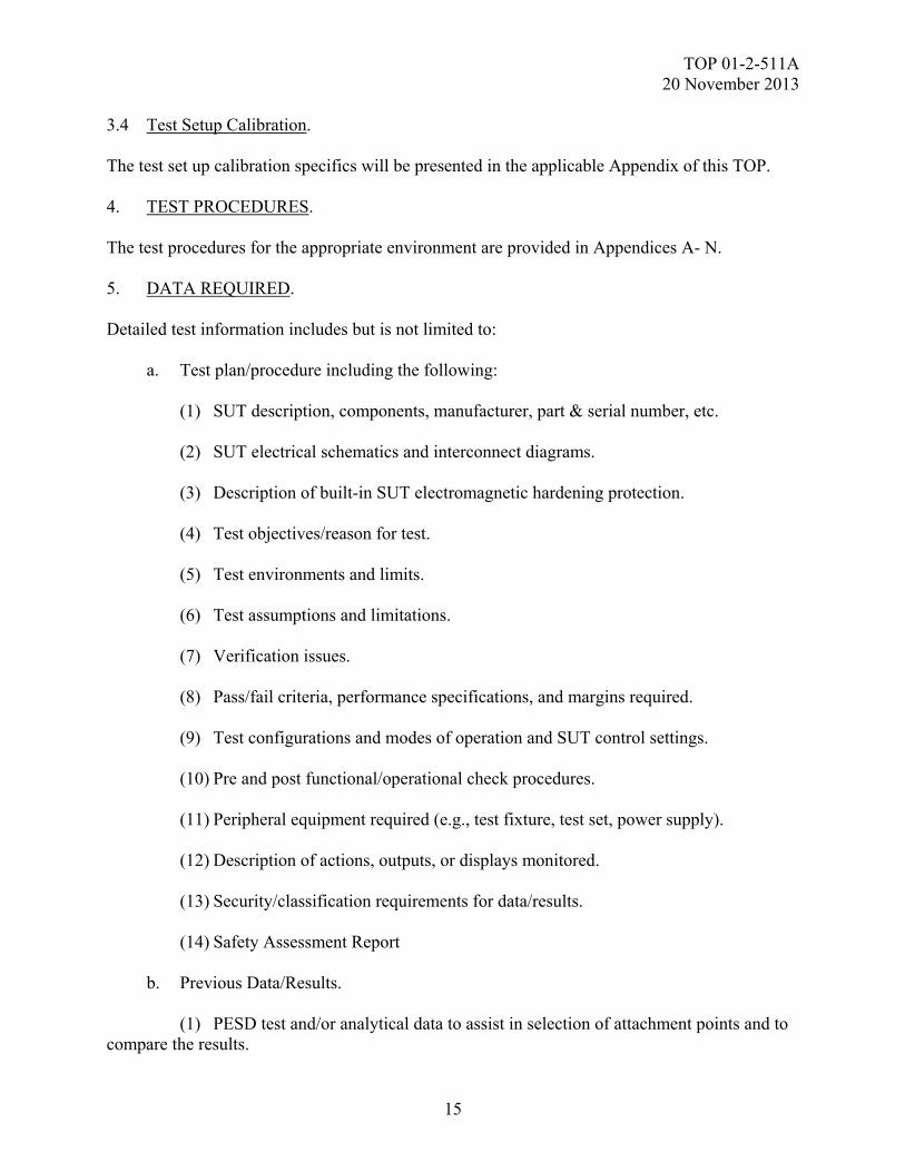
(2) There are specific power requirements that are regularly utilized for shelters, or mobile systems. An onsite power source for these items may be necessary in order to test the system while utilizing all possible power sources. It is best to separate the system power source from the facility power source to preclude interference into the test setup. (3) System interfaces. (4) Description of built-in SUT electromagnetic hardening protection. (5) Test environments and limits. (6) Verification issues. (7) Pass/fail criteria, performance specifications, and margins required.
(8) Test configurations and modes of operation and SUT control settings. (9) Peripheral equipment required (e.g., test fixture, test set, power supply). (10) Description of actions, outputs, or displays monitored. (11) Security/classification requirements for data/results. (12) EID electrical parameters data sheets for HERO calibration and data collection. (13) Safety Assessment Report (SAR).
b. When Built in Test Equipment (BITE) or other system status monitors are not used to observe test item performance, the test item will be instrumented using one of the methods outlined in Section 2.2. The preferred method to properly test and evaluate the operational performance of a system/platform, the system must be operated (to include communicating) during illumination. Trained operators are required. Monitoring of the test environment is required to insure that operators are not exposed above the Maximum Permissible Exposure (MPE) as recommend by Department of Defense Instruction (DODI) 6055.1112 for protection of personnel from electromagnetic fields. These operators will run the system in the approved scenario and allow the test item to recover when an anomaly or susceptibility is encountered, or apply operator procedures for system recovery. For example, a M1 Abrams tank requires a minimum of three operators and a base station of Blue Comms for communication during each illumination. At a minimum, there should be a method to stimulate the system in order to perform the operational functions monitor responses and implement crew intervention (when allowed by system’s requirements). 3.2 Pre-Test Evaluation. A pre-test evaluation is performed to include the following. This evaluation is used for test planning and can often reduce the amount of testing required.

TOP 01-2-511A 20 November 2013
12
a. Determine test points as applicable. b. Determine the primary current paths. c. Determine the most/least susceptible SUT configurations. d. Determine the most/least susceptible SUT modes of operation. e. Determine the possible points of entry (POEs) for the electromagnetic energy. f. Determine the bulk current measurement points. g. Perform an energy coupling analysis to identify the type and capability requirements for the data acquisition system. h. Determine critical SUT data required to be instrumented and monitored. i. Determine which EIDs are to be instrumented and measured and how. j. Determine SUT/platform critical functions and circuits. k. Determine SUT EM protection features and their predicted performance and whether they are repairable or replaceable. l. Determine verification and pass/fail criteria and required safety margins. m. Determine the SUT operating and checkout procedures. n. Pre-existing analyses and test data from previous tests may be evaluated and incorporated into the test planning and pretest analysis in order to enhance and reduce the scope of the new testing. 3.3 Policy and Guidance. a. Maximum Permissible Exposure (MPE). Care should be taken to ensure that when utilizing personnel in all phases of testing that the exposure limits are strictly enforced. In particular, for peak power testing and where the MPE is exceeded, in some of the frequency ranges it will be necessary to limit the exposure of personnel through time averaging. Personnel exposure to electromagnetic signals and physical proximity to radiating elements should be minimized and can be exacerbated in personnel with metallic implants. Also ensure that in areas with localized exposures above the MPE that the actual whole-body or spatial peak SARs is not exceeded. Be aware of the possibility of hazardous contact currents, and address according to the site specific facility or system guidance. Utilize methods from Institute of Electrical and Electronics Engineers (IEEE) C95.3-200213, Recommended Practice for Measurements and
TOP 01-2-511A 20 November 2013
13
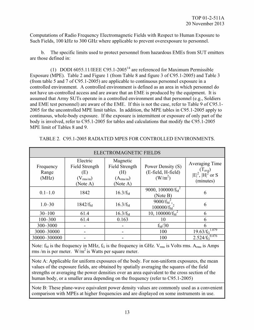
Computations of Radio Frequency Electromagnetic Fields with Respect to Human Exposure to Such Fields, 100 kHz to 300 GHz where applicable to prevent overexposure to personnel. b. The specific limits used to protect personnel from hazardous EMEs from SUT emitters are those defined in: (1) DODI 6055.11/IEEE C95.1-200514 are referenced for Maximum Permissible Exposure (MPE). Table 2 and Figure 1 (from Table 8 and figure 3 of C95.1-2005) and Table 3 (from table 5 and 7 of C95.1-2005) are applicable to continuous personnel exposure in a controlled environment. A controlled environment is defined as an area in which personnel do not have un-controlled access and are aware that an EME is produced by the equipment. It is assumed that Army SUTs operate in a controlled environment and that personnel (e.g., Soldiers and EME test personnel) are aware of the EME. If this is not the case, refer to Table 9 of C95.1-2005 for the uncontrolled MPE limit tables. In addition, the MPE tables in C95.1-2005 apply to continuous, whole-body exposure. If the exposure is intermittent or exposure of only part of the body is involved, refer to C95.1-2005 for tables and calculations that modify the C95.1-2005 MPE limit of Tables 8 and 9.
TABLE 2. C95.1-2005 RADIATED MPES FOR CONTROLLED ENVIRONMENTS.
ELECTROMAGNETIC FIELDS
Frequency Range (MHz)
Electric Field Strength
(E) (Vrms/m) (Note A)
Magnetic Field Strength
(H) (Arms/m) (Note A)
Power Density (S) (E-field, H-field)
(W/m2)
Averaging Time (Tavg)
|E|2, |H|2 or S (minutes)
0.1–1.0 1842 16.3/fM 9000, 100000/fM
2 (Note B)
6
1.0–30 1842/fM 16.3/fM 9000/fM
2, 100000/fM
2 6
30–100 61.4 16.3/fM 10, 100000/fM2 6
100–300 61.4 0.163 10 6 300–3000 - - fM/30 6
3000–30000 - - 100 19.63/fG1.079
30000–300000 - - 100 2.524/fG0.476
Note: fM is the frequency in MHz, fG is the frequency in GHz. Vrms is Volts rms. Arms is Amps rms /m is per meter. W/m2 is Watts per square meter.
Note A: Applicable for uniform exposures of the body. For non-uniform exposures, the mean values of the exposure fields, are obtained by spatially averaging the squares of the field strengths or averaging the power densities over an area equivalent to the cross section of the human body, or a smaller area depending on the frequency (refer to C95.1-2005)
Note B: These plane-wave equivalent power density values are commonly used as a convenient comparison with MPEs at higher frequencies and are displayed on some instruments in use.
TOP 01-2-511A 20 November 2013
14
0.1
1
10
100
1,000
10,000
0.01M 0.1M 1M 10M 100M 1G 10G 100G 1,000G
Frequency (Hz)
Ele
ctri
c F
ield
Str
eng
th (
Vrm
s/m
)M
agn
etic
Fie
ld (
Arm
s/m
)
0.1
1
10
100
1,000
10,000
Po
we
r D
ens
ity
(mW
/cm
2)
ElectricField Strength (E)
(Vrms/m)
MagneticField Strength (E)
(Arms/m)
Power Density (S)(mW/cm2)
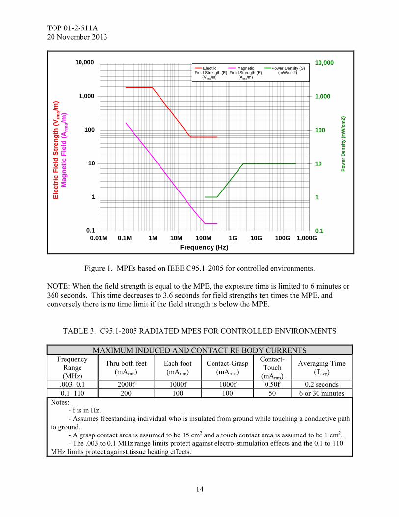
Figure 1. MPEs based on IEEE C95.1-2005 for controlled environments. NOTE: When the field strength is equal to the MPE, the exposure time is limited to 6 minutes or 360 seconds. This time decreases to 3.6 seconds for field strengths ten times the MPE, and conversely there is no time limit if the field strength is below the MPE.
TABLE 3. C95.1-2005 RADIATED MPES FOR CONTROLLED ENVIRONMENTS
MAXIMUM INDUCED AND CONTACT RF BODY CURRENTS Frequency
Range (MHz)
Thru both feet (mArms)
Each foot (mArms)
Contact-Grasp (mArms)
Contact-Touch
(mArms)
Averaging Time (Tavg)
.003–0.1 2000f 1000f 1000f 0.50f 0.2 seconds 0.1–110 200 100 100 50 6 or 30 minutes
Notes: - f is in Hz. - Assumes freestanding individual who is insulated from ground while touching a conductive path to ground. - A grasp contact area is assumed to be 15 cm2 and a touch contact area is assumed to be 1 cm2. - The .003 to 0.1 MHz range limits protect against electro-stimulation effects and the 0.1 to 110 MHz limits protect against tissue heating effects.
TOP 01-2-511A 20 November 2013
15
3.4 Test Setup Calibration. The test set up calibration specifics will be presented in the applicable Appendix of this TOP. 4. TEST PROCEDURES. The test procedures for the appropriate environment are provided in Appendices A- N. 5. DATA REQUIRED. Detailed test information includes but is not limited to: a. Test plan/procedure including the following: (1) SUT description, components, manufacturer, part & serial number, etc. (2) SUT electrical schematics and interconnect diagrams. (3) Description of built-in SUT electromagnetic hardening protection. (4) Test objectives/reason for test. (5) Test environments and limits. (6) Test assumptions and limitations. (7) Verification issues. (8) Pass/fail criteria, performance specifications, and margins required. (9) Test configurations and modes of operation and SUT control settings. (10) Pre and post functional/operational check procedures. (11) Peripheral equipment required (e.g., test fixture, test set, power supply). (12) Description of actions, outputs, or displays monitored. (13) Security/classification requirements for data/results. (14) Safety Assessment Report b. Previous Data/Results. (1) PESD test and/or analytical data to assist in selection of attachment points and to compare the results.
TOP 01-2-511A 20 November 2013
16
(2) Results of functional/operational and pre/posttest inspection checks. (3) Results of each test run, test data sheets, plots and strip chart outputs. (4) Results of calibration runs and calibration data sheets. (5) Test log detailing chronological test events. (6) Description of all anomalies, anomaly investigations, and results. (7) Test Incident Reports (TIRs). (8) Changes/redlines to the test plan/procedure. (9) Indications of compliance. (10) Drawings and photographs of test setups and investigations. (11) Data analysis results if performed during testing. (12) Listing of test facility equipment used for each test along with the equipment manufacturer, model number, serial number, and calibration due date. c. The data required for each applicable E3 test are listed in the related appendices. 6. PRESENTATION OF DATA. Data to be collected shall be as follows: a. List of subsystems that comprise the test item. b. List of monitoring equipment used. c. SUT details (e.g., hardware and operational description, model and serial numbers) as well as applicable specific EID parameters. d. Drawings and/or photographs of test setups, instrumentation setups and any physical damage resulting from test. e. List all test and instrumentation equipment with applicable calibration data, calibration due dates, and transducer/cable factors used. f. Include test instrumentation system checkout and pretest SUT checkout results (plots, graphs, data tables) used. g. Test configurations/modes/operational procedures used.
TOP 01-2-511A 20 November 2013
17
h. Results (e.g., plots, graphs, data tables). Sample of data/results examples are shown in individual test methods. Note: Data should be reported at the level of accuracy of the test equipment. i. Notes of test operators, conductors, and engineer. 6.1 Data Analysis. a. Test data will be compared and evaluated against the criteria set forth in MIL-STD-464C, the SUT specification, and SUT test plan to determine if the SUT met the criteria. For Army, Aviation refer to ADS-37A, and TACOM systems ATPD-2407. Deficiencies will be identified, and discussed in the test report. b. The test data will be compared to the applicable criteria and the pre-event baseline measurements to determine the extent to which the test criteria are met and the effects of the test environment on the SUT. Pre-existing analyses and test data from previous tests may also be used as a comparison for the new test data. Test anomalies will be assessed to determine if they should be classified as SUT failures. Failures or degradation resulting in SUT performance outside specifications, will be addressed with regards to causes, test level at which they occurred, allowable downtime, and mission impact. The test system configuration will be evaluated against the expected production configuration and the differences documented. Corrective hardening and/or mitigation recommendations may be suggested, developed and documented. EID safety margins, as calculated below that could seriously impact mission performance or safety, should be discussed with regard to mission performance or outcome in the applicable test plan and report. 6.2 Safety Margins. a. There are two classifications of EID situations, safety and reliability. When safety margins are necessary, IAW MIL-STD-464C, safety (hazardous) EIDs shall maintain a 16.5 dB safety factor below the Maximum No Fire value (MNF) (based on not exceeding 15 percent of the EID MNF) and reliability (nonhazardous) EIDs shall maintain a 6 dB safety factor below the MNF (based on not exceeding 50 percent of the MNF). There is also the situation where the EIDs are out of line. In most cases this becomes a reliability situation (see also MIL-HDBK-240A). b. Safety margins are calculated using a number of equations depending on the test data obtained. HERO safety testing consists of testing EIDs, ESADs and other firing circuits. These may also be E3 safety tested as part of PESD, HESD, NSL, DSL, and HEMP testing. JOTP-061 should be used for guidance in testing of munitions to HERO. A second JOTP is in process and should be used for guidance of joint munition ESD and Lightning testing. The following discusses the different sensors used and their resulting test data. (1) The instrumentation sensor used for testing EIDs to a transient environment (PESD, HESD, NSL, DSL and HEMP) is a current probe (e.g., EG&G, Nanofast or Pearson) EID specifications often specify a MNFC. However, this specification is a DC test value, not a transient test value and cannot be used to determine an accurate safety margin. Therefore, the
TOP 01-2-511A 20 November 2013
18
current test data is integrated over time and then is multiplied by the resistance using the equation:
dtxRIE 2^
to obtain the energy. Often, the MNFE to use to calculate the safety margin is also not available. When empirical maximum no fire energy (MNFE) for a specific, qualified, one-Ohm, one-Amp, one-Watt no-fire EID is lacking, the Army may use a level of 17.6 milli-Joules (mJ) based on previous testing of a series of Stinger launch/flight motor EIDs when approved by the Army procuring authority and system evaluator. (2) The instrumentation sensor used for testing ESADs to a transient environment (PESD, HESD, NSL, DSL, and HEMP) is a voltage probe (e.g., EG&G***, Nanofast or Pearson) across a voltage divider network. Again, the ESAD maximum fire voltage (MFV) of the ESAD firing capacitor may not be available. Most firing capacitor MFVs are in the 1000 to 2000 Volt range. MIL-STD-1316E15, specifies a minimum firing voltage of 500 Volts for an ESAD. This conservative value is typically used when the MFV is not known. In addition, many ESADs often are coupled with a mechanical Safe and Arm Device (SAD) which further increases overall safety. The mechanical SAD is usually locked into the Arm position during E3 safety testing in order to test the ESAD in its worst case configuration (and which is usually necessary to obtain access to the ESAD electrical leads). If this is not the case and the ESAD is out of line this becomes a reliability situation (see MIL-HDBK-240A). (3) The instrumentation sensor used for testing EIDs to the HERO CW environment is a relatively fast acting fiber optic sensor (e.g., OPSENS or FISO) that is placed directly against the EID bridgewire to measure the heating induced on the bridgewire by the test environment which is, in turn, directly relatable to the current induced on the bridgewire. See paragraph 3.2.c (1) for additional transient instrumentation utilized for Peak pulse modulation testing on EIDs. c. Safety margins are calculated depending on the type of data measured which was discussed above. The safety margin calculations corresponding to the data measured are as follows: (1) For transient testing, the current is measured but is converted, as described above, to energy. The following safety margin equation is used:
ENERGY SM (dB) = 10 log 10 (EMNF/E Induced) where: EMNF = Max No-Fire energy of EID. Typically 17.6.milli-Joules E Induced = measured energy induced in the EID circuit (J)
**The use of brand names does not constitute endorsement by the Army or any other agency of the Federal Government, nor does it imply that it is best suited for its intended application.
TOP 01-2-511A 20 November 2013
19
Note: If the induced current in the EID or firing circuit is below what can be measured by the instrumentation, Minimum Detectable Current (MDC) is used for a conservative safety margin. Previous test programs have used 17.6 mJ as the MNFE for safety margin calculations for MIL-DTL-2365916. The MNFE value was established during testing of a series of Stinger Launch/Flight motor EIDs. The EID testing evaluated 72 initiators tested with a one amp per millisecond current ramp. The data were used to derive the MNFE and is documented in technical document RD-TE-87-4, MLRS AT2 Lightning Test Report17. (2) For a regular firing circuit (e.g., a gun firing trigger safety circuit), induced current is usually measured and used to calculate the safety margin with the known required firing current. If the true transient MNFE is known for an EID, the EID current is used to calculate the safety margin as follows:
CURRENT: SM (dB) = 20 log 10 (IMNF/I Induced) where: IMNF = Maximum No-Fire current of EID (A) I Induced = measured value for the induced EID current (A) (or Minimum Discernible Current, MDC, if signal below MDC)
(3) For ESADs and other capacitive firing circuits, induced voltage is measured (often using a voltage divider as the typical firing voltage is in the 1000 to 2000 Volt range) and used to calculate the safety margin. If the true MFV is not known, MIL-STD-1316 specifies a minimum firing voltage of 500 Volts for an ESAD and this conservative value is used. Note that if the induced voltage at the ESAD firing capacitor or firing circuit is below what can be measured by the instrumentation, the MDV is used for a conservative safety margin:
VOLTAGE: SM(dB) = 20 log 10 (MFV/V Induced) where: MFV = ESAD capacitor Minimum Firing Voltage (MFV) (Often 500 Volts2) V Induced = measured value for the induced ESAD capacitor firing voltage (or minimum discernible voltage (MDV) if signal below MDV).
Note: MIL-STD-1316 requirement for minimum firing voltage = 500 Volts. Most initiators have minimum firing voltages in the 1000 to 2000 Volt range. This should only be utilized when an instrumented safety factor is required, and the methodology is agreed upon by the system Army E3 Board. JOTP-061 should be used for guidance in testing of joint munitions to HERO. A second JOTP is in process and should be used for guidance of ESD and Lightning testing
TOP 01-2-511A 20 November 2013
20
7. SUGGESTED MINIMUM E3 TESTING. a. The suggested Minimum E3 Test Matrices were developed by the ATEC, ATEC Test Centers, and AEC Evaluators. They were developed to provide guidance to test program systems that are unable to determine the appropriate E3 tests that should be performed for their category of materiel, or will not meet safety and performance requirements based on the item specification or contract requirements. They were also developed to address the need for Army E3 Requirements Boards on smaller Soldier items and consistency for delivery of safe and functional items to the Users. There are two matrices included; Table 4 - Minimum E3 for Safety, and Table 5 - Minimum E3 for Full Qualification. Table 4 is provided as guidance on those programs requiring a Safety Release, Rapid Fielding programs and possibly Urgent Materiel Release of items that have been previously fully qualified. The E3 Board and System Evaluator should review the system based on the complexity of changes to the system and their effect on the E3 integrity of the total system. Table 5 is provided as guidance for full qualification on those programs with little, none or insufficient E3 requirements. As with all programs the E3 Review Board and System Evaluator should agree upon the final tests and assessments to be performed. b. Worst Case Example for Table 4: Weaponized Predator – Categorize as Aircraft, Transmitter/Receiver, Ordnance, Weapon System, and Unmanned Air Vehicle. The suggested tests for the inclusive categories include Source/Victim, Radio Desense/Noise Floor, EID/HERO, External RF EME, DSL, NSL, HESD, PESD Ordnance, PESD Electronics, HERP, HERF, HERO, Bonds and Grounds and Spectrum supportability. The Source/Victim, Radio Desense/Noise Floor and EID/HERO tests are suggested to ensure the control links/transmitters are not operating above the specified power for personnel hazards, and for safety to the weapon from inadvertent actuation by onboard transmitters. The External RF EME is suggested to ensure no uncommanded movements or loss of flight control links is noted. The DSL and NSL are also conducted for safety of ordnance (ordnance should not go high order) and loss of control links. ESD tests are suggested for safety of ordnance and damage to electronics, as well as the RADHAZ for safety to personnel and fuel. Theoretically, a sound Bonds and Grounds is the best way to start integration of a successful platform. Finally, all system transmitters must maintain spectrum supportability in accordance with applicable requirements.
TO
P 01-2-511A
20 N
ovember 2013
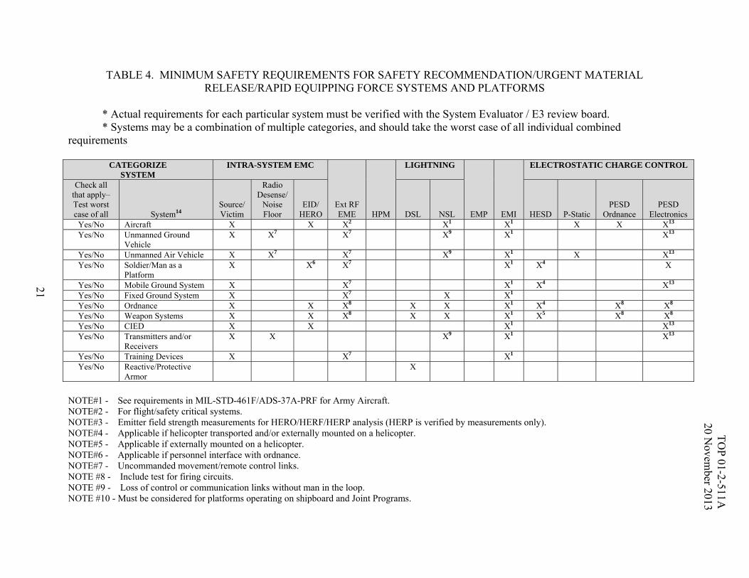
21 TABLE 4. MINIMUM SAFETY REQUIREMENTS FOR SAFETY RECOMMENDATION/URGENT MATERIAL
RELEASE/RAPID EQUIPPING FORCE SYSTEMS AND PLATFORMS * Actual requirements for each particular system must be verified with the System Evaluator / E3 review board. * Systems may be a combination of multiple categories, and should take the worst case of all individual combined requirements
CATEGORIZE SYSTEM
INTRA-SYSTEM EMC
Ext RF EME HPM
LIGHTNING
EMP EMI
ELECTROSTATIC CHARGE CONTROL
Check all that apply– Test worst case of all System14
Source/ Victim
Radio Desense/
Noise Floor
EID/ HERO DSL NSL HESD P-Static
PESD Ordnance
PESD Electronics
Yes/No Aircraft X X X2 X1 X1 X X X13 Yes/No Unmanned Ground
Vehicle X X7 X7 X9 X1 X13
Yes/No Unmanned Air Vehicle X X7 X7 X9 X1 X X13 Yes/No Soldier/Man as a
Platform X X6 X7 X1 X4 X
Yes/No Mobile Ground System X X7 X1 X4 X13 Yes/No Fixed Ground System X X7 X X1 Yes/No Ordnance X X X8 X X X1 X4 X8 X8 Yes/No Weapon Systems X X X8 X X X1 X5 X8 X8 Yes/No CIED X X X1 X13 Yes/No Transmitters and/or
Receivers X X X9 X1 X13
Yes/No Training Devices X X7 X1 Yes/No Reactive/Protective
Armor X
NOTE#1 - See requirements in MIL-STD-461F/ADS-37A-PRF for Army Aircraft. NOTE#2 - For flight/safety critical systems. NOTE#3 - Emitter field strength measurements for HERO/HERF/HERP analysis (HERP is verified by measurements only). NOTE#4 - Applicable if helicopter transported and/or externally mounted on a helicopter. NOTE#5 - Applicable if externally mounted on a helicopter. NOTE#6 - Applicable if personnel interface with ordnance. NOTE#7 - Uncommanded movement/remote control links. NOTE #8 - Include test for firing circuits. NOTE #9 - Loss of control or communication links without man in the loop. NOTE #10 - Must be considered for platforms operating on shipboard and Joint Programs.

TO
P 01-2-511A
20 N
ovember 2013
22 TABLE 4 NOTES (CONT’D)
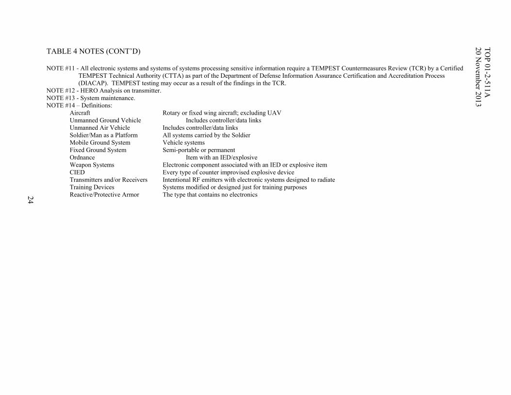
NOTE #11 - All electronic systems and systems of systems processing sensitive information require a TEMPEST Countermeasures Review (TCR) by a Certified
TEMPEST Technical Authority (CTTA) as part of the Department of Defense Information Assurance Certification and Accreditation Process (DIACAP). TEMPEST testing may occur as a result of the findings in the TCR.
NOTE #12 - HERO Analysis on transmitter. NOTE #13 - System maintenance. NOTE #14 – Definitions: Aircraft Rotary or fixed wing aircraft; excluding UAV Unmanned Ground Vehicle Includes controller/data links Unmanned Air Vehicle Includes controller/data links Soldier/Man as a Platform All systems carried by the Soldier Mobile Ground System Vehicle systems Fixed Ground System Semi-portable or permanent Ordnance Item with an IED/explosive Weapon Systems Electronic component associated with an IED or explosive item CIED Every type of counter improvised explosive device Transmitters and/or Receivers Intentional RF emitters with electronic systems designed to radiate Training Devices Systems modified or designed just for training purposes Reactive/Protective Armor The type that contains no electronics
TO
P 01-2-511A
20 N
ovember 2013
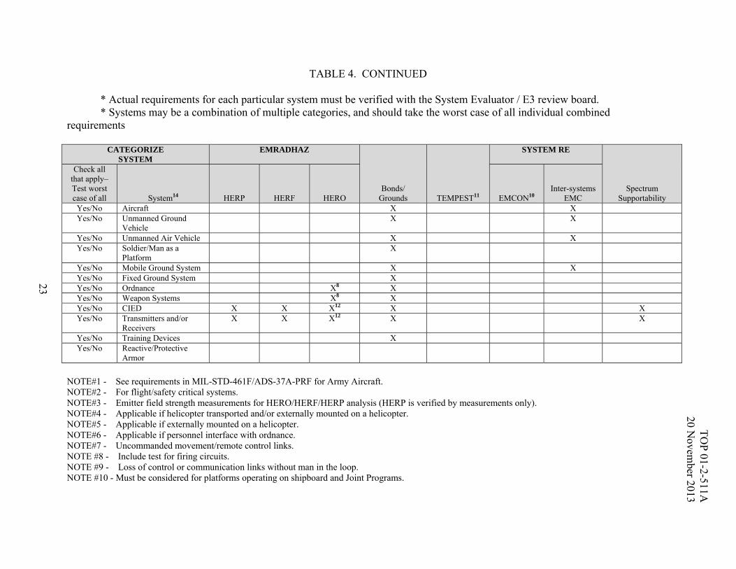
23 TABLE 4. CONTINUED
* Actual requirements for each particular system must be verified with the System Evaluator / E3 review board. * Systems may be a combination of multiple categories, and should take the worst case of all individual combined requirements
CATEGORIZE SYSTEM
EMRADHAZ
Bonds/ Grounds TEMPEST11
SYSTEM RE
Spectrum Supportability
Check all that apply– Test worst case of all System14 HERP HERF HERO EMCON10
Inter-systems EMC
Yes/No Aircraft X X Yes/No Unmanned Ground
Vehicle X X
Yes/No Unmanned Air Vehicle X X Yes/No Soldier/Man as a
Platform X
Yes/No Mobile Ground System X X Yes/No Fixed Ground System X Yes/No Ordnance X8 X Yes/No Weapon Systems X8 X Yes/No CIED X X X12 X X Yes/No Transmitters and/or
Receivers X X X12 X X
Yes/No Training Devices X Yes/No Reactive/Protective
Armor
NOTE#1 - See requirements in MIL-STD-461F/ADS-37A-PRF for Army Aircraft. NOTE#2 - For flight/safety critical systems. NOTE#3 - Emitter field strength measurements for HERO/HERF/HERP analysis (HERP is verified by measurements only). NOTE#4 - Applicable if helicopter transported and/or externally mounted on a helicopter. NOTE#5 - Applicable if externally mounted on a helicopter. NOTE#6 - Applicable if personnel interface with ordnance. NOTE#7 - Uncommanded movement/remote control links. NOTE #8 - Include test for firing circuits. NOTE #9 - Loss of control or communication links without man in the loop. NOTE #10 - Must be considered for platforms operating on shipboard and Joint Programs.
TO
P 01-2-511A
20 N
ovember 2013
24 TABLE 4 NOTES (CONT’D)
NOTE #11 - All electronic systems and systems of systems processing sensitive information require a TEMPEST Countermeasures Review (TCR) by a Certified
TEMPEST Technical Authority (CTTA) as part of the Department of Defense Information Assurance Certification and Accreditation Process (DIACAP). TEMPEST testing may occur as a result of the findings in the TCR.
NOTE #12 - HERO Analysis on transmitter. NOTE #13 - System maintenance. NOTE #14 – Definitions: Aircraft Rotary or fixed wing aircraft; excluding UAV Unmanned Ground Vehicle Includes controller/data links Unmanned Air Vehicle Includes controller/data links Soldier/Man as a Platform All systems carried by the Soldier Mobile Ground System Vehicle systems Fixed Ground System Semi-portable or permanent Ordnance Item with an IED/explosive Weapon Systems Electronic component associated with an IED or explosive item CIED Every type of counter improvised explosive device Transmitters and/or Receivers Intentional RF emitters with electronic systems designed to radiate Training Devices Systems modified or designed just for training purposes Reactive/Protective Armor The type that contains no electronics
TO
P 01-2-511A
20 N
ovember 2013
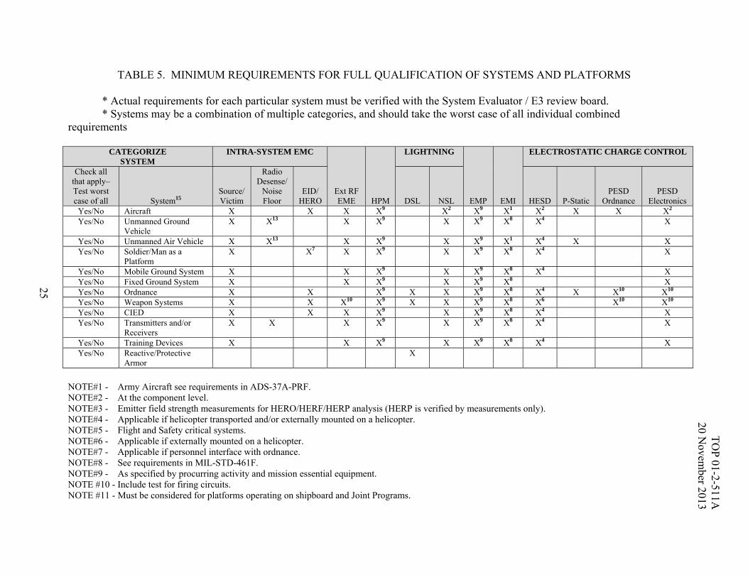
25 TABLE 5. MINIMUM REQUIREMENTS FOR FULL QUALIFICATION OF SYSTEMS AND PLATFORMS
* Actual requirements for each particular system must be verified with the System Evaluator / E3 review board. * Systems may be a combination of multiple categories, and should take the worst case of all individual combined requirements
CATEGORIZE SYSTEM
INTRA-SYSTEM EMC
Ext RF EME HPM
LIGHTNING
EMP EMI
ELECTROSTATIC CHARGE CONTROL
Check all that apply– Test worst case of all System15
Source/ Victim
Radio Desense/
Noise Floor
EID/ HERO DSL NSL HESD P-Static
PESD Ordnance
PESD Electronics
Yes/No Aircraft X X X X9 X2 X9 X1 X2 X X X2 Yes/No Unmanned Ground
Vehicle X X13 X X9 X X9 X8 X4 X
Yes/No Unmanned Air Vehicle X X13 X X9 X X9 X1 X4 X X Yes/No Soldier/Man as a
Platform X X7 X X9 X X9 X8 X4 X
Yes/No Mobile Ground System X X X9 X X9 X8 X4 X Yes/No Fixed Ground System X X X9 X X9 X8 X Yes/No Ordnance X X X9 X X X9 X8 X4 X X10 X10 Yes/No Weapon Systems X X X10 X9 X X X9 X8 X6 X10 X10 Yes/No CIED X X X X9 X X9 X8 X4 X Yes/No Transmitters and/or
Receivers X X X X9 X X9 X8 X4 X
Yes/No Training Devices X X X9 X X9 X8 X4 X Yes/No Reactive/Protective
Armor X
NOTE#1 - Army Aircraft see requirements in ADS-37A-PRF. NOTE#2 - At the component level. NOTE#3 - Emitter field strength measurements for HERO/HERF/HERP analysis (HERP is verified by measurements only). NOTE#4 - Applicable if helicopter transported and/or externally mounted on a helicopter. NOTE#5 - Flight and Safety critical systems. NOTE#6 - Applicable if externally mounted on a helicopter. NOTE#7 - Applicable if personnel interface with ordnance. NOTE#8 - See requirements in MIL-STD-461F. NOTE#9 - As specified by procurring activity and mission essential equipment. NOTE #10 - Include test for firing circuits. NOTE #11 - Must be considered for platforms operating on shipboard and Joint Programs.

TO
P 01-2-511A
20 N
ovember 2013
26 TABLE 5 NOTES (CONT’D)
NOTE #12 - All electronic systems and systems of systems processing sensitive information require a TEMPEST Countermeasures Review (TCR) by a Certified
TEMPEST Technical Authority (CTTA) as part of the Department of Defense Information Assurance Certification and Accreditation Process (DIACAP). TEMPEST testing may occur as a result of the findings in the TCR.
NOTE #13 - Uncommanded movement/remote control links. NOTE #14 - HERO Analysis on transmitter. NOTE #15 – Definitions: Aircraft Rotary or fixed wing aircraft; excluding UAV Unmanned Ground Vehicle Includes controller/data links Unmanned Air Vehicle Includes controller/data links Soldier/Man as a Platform All systems carried by the Soldier Mobile Ground System Vehicle systems Fixed Ground System Semi-portable or permanent Ordnance Item with an IED/explosive Weapon Systems Electronic component associated with an IED or explosive item CIED Every type of counter improvised explosive device Transmitters and/or Receivers Intentional RF emitters with electronic systems designed to radiate Training Devices Systems modified or designed just for training purposes Reactive/Protective Armor The type that contains no electronics
TO
P 01-2-511A
20 N
ovember 2013
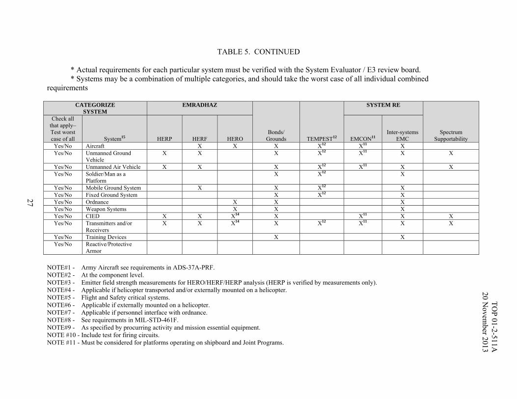
27 TABLE 5. CONTINUED
* Actual requirements for each particular system must be verified with the System Evaluator / E3 review board. * Systems may be a combination of multiple categories, and should take the worst case of all individual combined requirements
CATEGORIZE SYSTEM
EMRADHAZ
Bonds/ Grounds TEMPEST12
SYSTEM RE
Spectrum Supportability
Check all that apply– Test worst case of all System15 HERP HERF HERO EMCON11
Inter-systems EMC
Yes/No Aircraft X X X X12 X11 X Yes/No Unmanned Ground
Vehicle X X X X12 X11 X X
Yes/No Unmanned Air Vehicle X X X X12 X11 X X Yes/No Soldier/Man as a
Platform X X12 X
Yes/No Mobile Ground System X X X12 X Yes/No Fixed Ground System X X12 X Yes/No Ordnance X X X Yes/No Weapon Systems X X X Yes/No CIED X X X14 X X11 X X Yes/No Transmitters and/or
Receivers X X X14 X X12 X11 X X
Yes/No Training Devices X X Yes/No Reactive/Protective
Armor
NOTE#1 - Army Aircraft see requirements in ADS-37A-PRF. NOTE#2 - At the component level. NOTE#3 - Emitter field strength measurements for HERO/HERF/HERP analysis (HERP is verified by measurements only). NOTE#4 - Applicable if helicopter transported and/or externally mounted on a helicopter. NOTE#5 - Flight and Safety critical systems. NOTE#6 - Applicable if externally mounted on a helicopter. NOTE#7 - Applicable if personnel interface with ordnance. NOTE#8 - See requirements in MIL-STD-461F. NOTE#9 - As specified by procurring activity and mission essential equipment. NOTE #10 - Include test for firing circuits. NOTE #11 - Must be considered for platforms operating on shipboard and Joint Programs.

TO
P 01-2-511A
20 N
ovember 2013
28 TABLE 4 NOTES (CONT’D)
NOTE #12 - All electronic systems and systems of systems processing sensitive information require a TEMPEST Countermeasures Review (TCR) by a Certified
TEMPEST Technical Authority (CTTA) as part of the Department of Defense Information Assurance Certification and Accreditation Process (DIACAP). TEMPEST testing may occur as a result of the findings in the TCR.
NOTE #13 - Uncommanded movement/remote control links. NOTE #14 - HERO Analysis on transmitter. NOTE #15 – Definitions: Aircraft Rotary or fixed wing aircraft; excluding UAV Unmanned Ground Vehicle Includes controller/data links Unmanned Air Vehicle Includes controller/data links Soldier/Man as a Platform All systems carried by the Soldier Mobile Ground System Vehicle systems Fixed Ground System Semi-portable or permanent Ordnance Item with an IED/explosive Weapon Systems Electronic component associated with an IED or explosive item CIED Every type of counter improvised explosive device Transmitters and/or Receivers Intentional RF emitters with electronic systems designed to radiate Training Devices Systems modified or designed just for training purposes Reactive/Protective Armor The type that contains no electronics
TOP 01-2-511A 20 November 2013
A-1
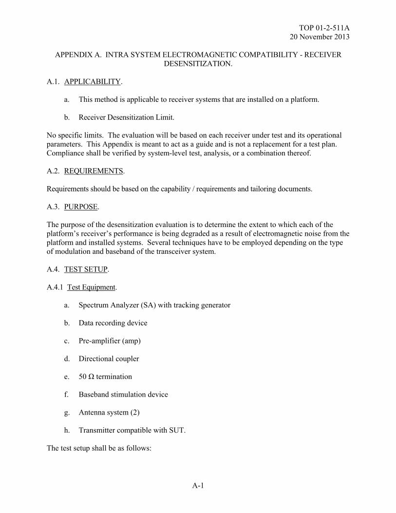
APPENDIX A. INTRA SYSTEM ELECTROMAGNETIC COMPATIBILITY - RECEIVER DESENSITIZATION.
A.1. APPLICABILITY. a. This method is applicable to receiver systems that are installed on a platform. b. Receiver Desensitization Limit. No specific limits. The evaluation will be based on each receiver under test and its operational parameters. This Appendix is meant to act as a guide and is not a replacement for a test plan. Compliance shall be verified by system-level test, analysis, or a combination thereof. A.2. REQUIREMENTS. Requirements should be based on the capability / requirements and tailoring documents. A.3. PURPOSE. The purpose of the desensitization evaluation is to determine the extent to which each of the platform’s receiver’s performance is being degraded as a result of electromagnetic noise from the platform and installed systems. Several techniques have to be employed depending on the type of modulation and baseband of the transceiver system. A.4. TEST SETUP. A.4.1 Test Equipment. a. Spectrum Analyzer (SA) with tracking generator b. Data recording device c. Pre-amplifier (amp) d. Directional coupler e. 50 Ω termination f. Baseband stimulation device g. Antenna system (2) h. Transmitter compatible with SUT. The test setup shall be as follows:
TOP 01-2-511A 20 November 2013
A-2
APPENDIX A. INTRA SYSTEM ELECTROMAGNETIC COMPATIBILITY - RECEIVER DESENSITIZATION.
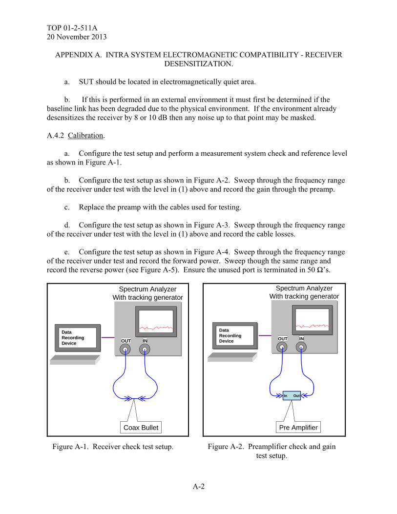
a. SUT should be located in electromagnetically quiet area.
b. If this is performed in an external environment it must first be determined if the
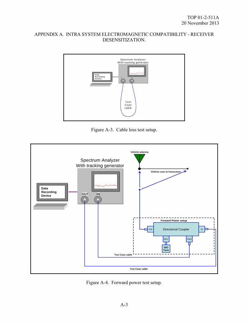
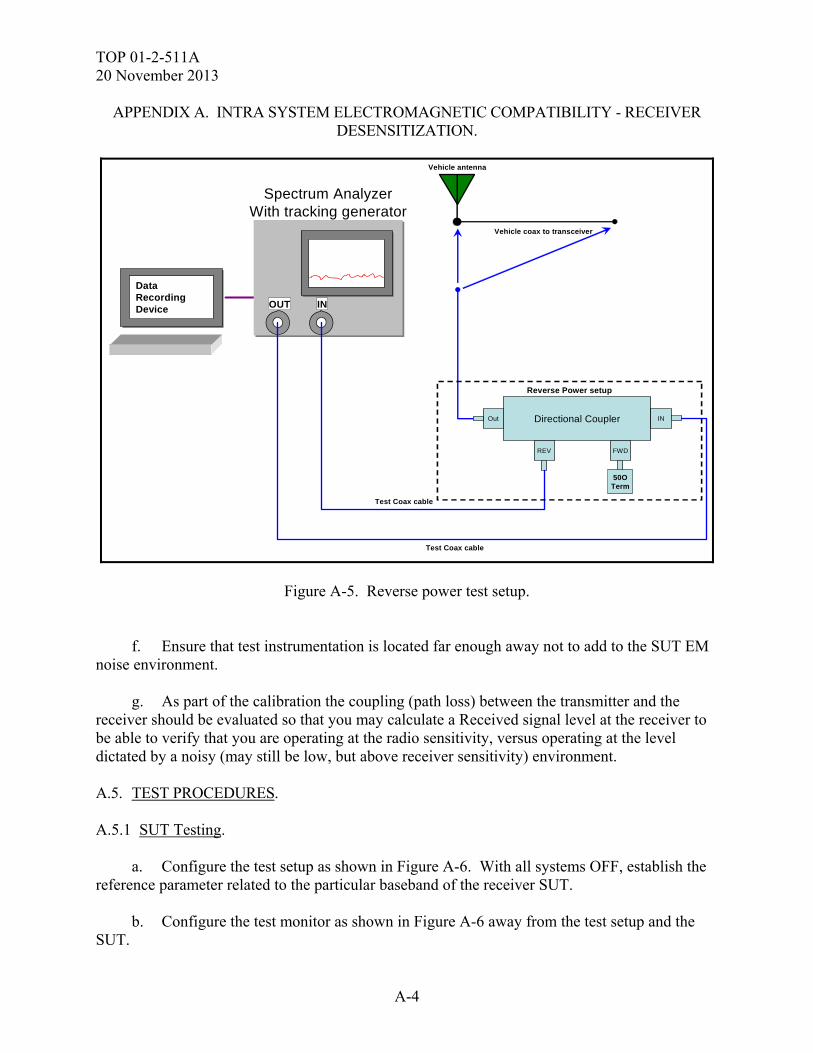
baseline link has been degraded due to the physical environment. If the environment already desensitizes the receiver by 8 or 10 dB then any noise up to that point may be masked. A.4.2 Calibration. a. Configure the test setup and perform a measurement system check and reference level as shown in Figure A-1. b. Configure the test setup as shown in Figure A-2. Sweep through the frequency range of the receiver under test with the level in (1) above and record the gain through the preamp. c. Replace the preamp with the cables used for testing. d. Configure the test setup as shown in Figure A-3. Sweep through the frequency range of the receiver under test with the level in (1) above and record the cable losses. e. Configure the test setup as shown in Figure A-4. Sweep through the frequency range of the receiver under test and record the forward power. Sweep though the same range and record the reverse power (see Figure A-5). Ensure the unused port is terminated in 50 Ω’s.
Coax Bullet
Data Recording Device
Data Recording Device
Spectrum AnalyzerWith tracking generator
OUT IN
Pre Amplifier
Data Recording Device
Data Recording Device
Spectrum AnalyzerWith tracking generator
OUT IN
In Out
Figure A-1. Receiver check test setup. Figure A-2. Preamplifier check and gain test setup.
TOP 01-2-511A 20 November 2013
A-3
APPENDIX A. INTRA SYSTEM ELECTROMAGNETIC COMPATIBILITY - RECEIVER DESENSITIZATION.
D ata R ecord ing D evice
D ata R ecord ing D evice
S pectrum A na lyze rW ith tracking genera to r
O U T IN
T estC oaxcab le
Figure A-3. Cable loss test setup.
Data Recording Device
Data Recording Device
Spectrum AnalyzerWith tracking generator
OUT IN
Test Coax cable
Directional CouplerOut
FWDREV
IN
Test Coax cable
Vehicle antenna
Vehicle coax to transceiver
50OTerm
Forward Power setup
Figure A-4. Forward power test setup.
TOP 01-2-511A 20 November 2013
A-4
APPENDIX A. INTRA SYSTEM ELECTROMAGNETIC COMPATIBILITY - RECEIVER DESENSITIZATION.
Data Recording Device
Data Recording Device
Spectrum AnalyzerWith tracking generator
OUT IN
Test Coax cable
Directional CouplerOut
FWDREV
IN
Test Coax cable
Vehicle antenna
Vehicle coax to transceiver
50OTerm
Reverse Power setup
Figure A-5. Reverse power test setup. f. Ensure that test instrumentation is located far enough away not to add to the SUT EM noise environment. g. As part of the calibration the coupling (path loss) between the transmitter and the receiver should be evaluated so that you may calculate a Received signal level at the receiver to be able to verify that you are operating at the radio sensitivity, versus operating at the level dictated by a noisy (may still be low, but above receiver sensitivity) environment. A.5. TEST PROCEDURES. A.5.1 SUT Testing. a. Configure the test setup as shown in Figure A-6. With all systems OFF, establish the reference parameter related to the particular baseband of the receiver SUT. b. Configure the test monitor as shown in Figure A-6 away from the test setup and the SUT.
TOP 01-2-511A 20 November 2013
A-5
APPENDIX A. INTRA SYSTEM ELECTROMAGNETIC COMPATIBILITY - RECEIVER DESENSITIZATION.
Receiver Under Test
BasebandStimulationequipment
Vehicle antenna
Vehicle coax
Cooperativetransmitter
BasebandStimulationequipment
transmit antenna
Data Recording Device
Data Recording Device
Spectrum AnalyzerWith tracking generator
OUT IN
TestCoaxcableSpectrum monitoring Station
RF port
Baseband
IN
Out
PreAmp
Platform under TestEnvironment Monitor antenna
Vehicle EM noise monitor
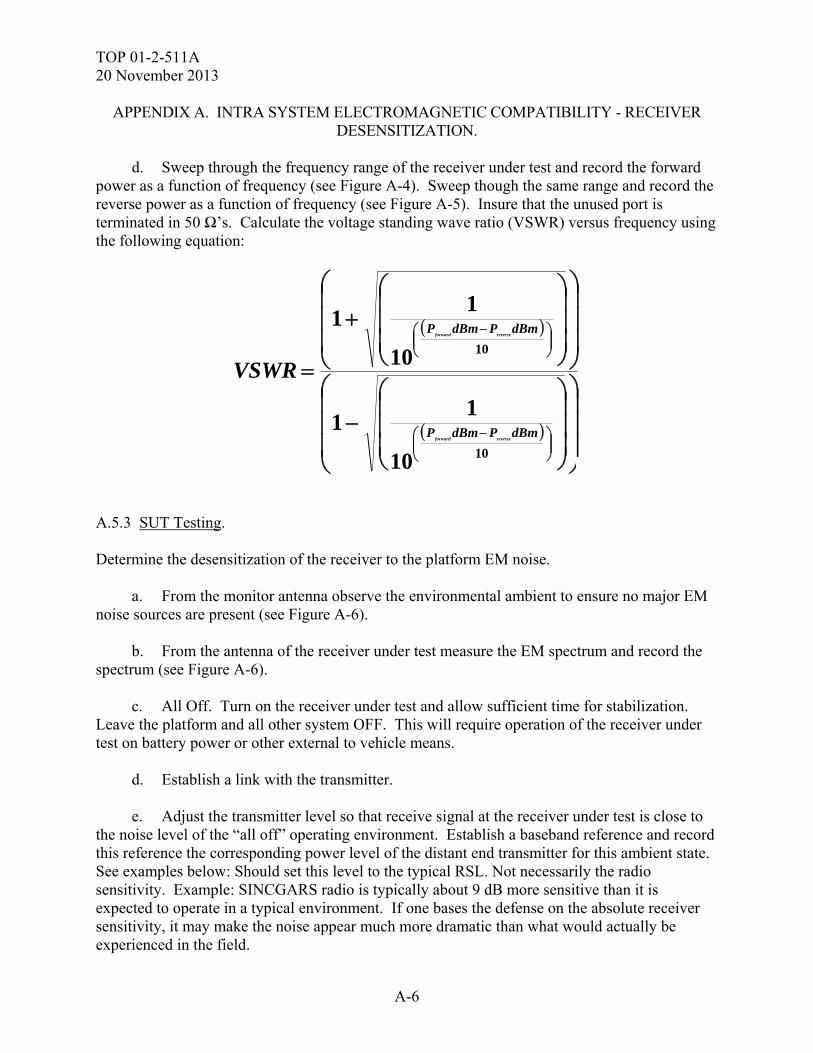
Figure A-6. Setup for desensitization and spectrum monitoring.
c. Turn ON measurement equipment and allow sufficient time for stabilization. A.5.2 Calibration. Evaluate the overall measurement system from the tracking generator to the SA.
a. Sweep through the frequency range of the receiver under test. Verify the levels out of the tracking generator match what is being displayed on the SA (see Figure A-1). b. Sweep through the frequency range of the receiver under test. Record the gain of the preamplifier as a function of frequency (see Figure A-2). c. Sweep through the frequency range of the receiver under test and record the loss through the test cables as a function of frequency (see Figure A-3).
TOP 01-2-511A 20 November 2013
A-6
APPENDIX A. INTRA SYSTEM ELECTROMAGNETIC COMPATIBILITY - RECEIVER DESENSITIZATION.
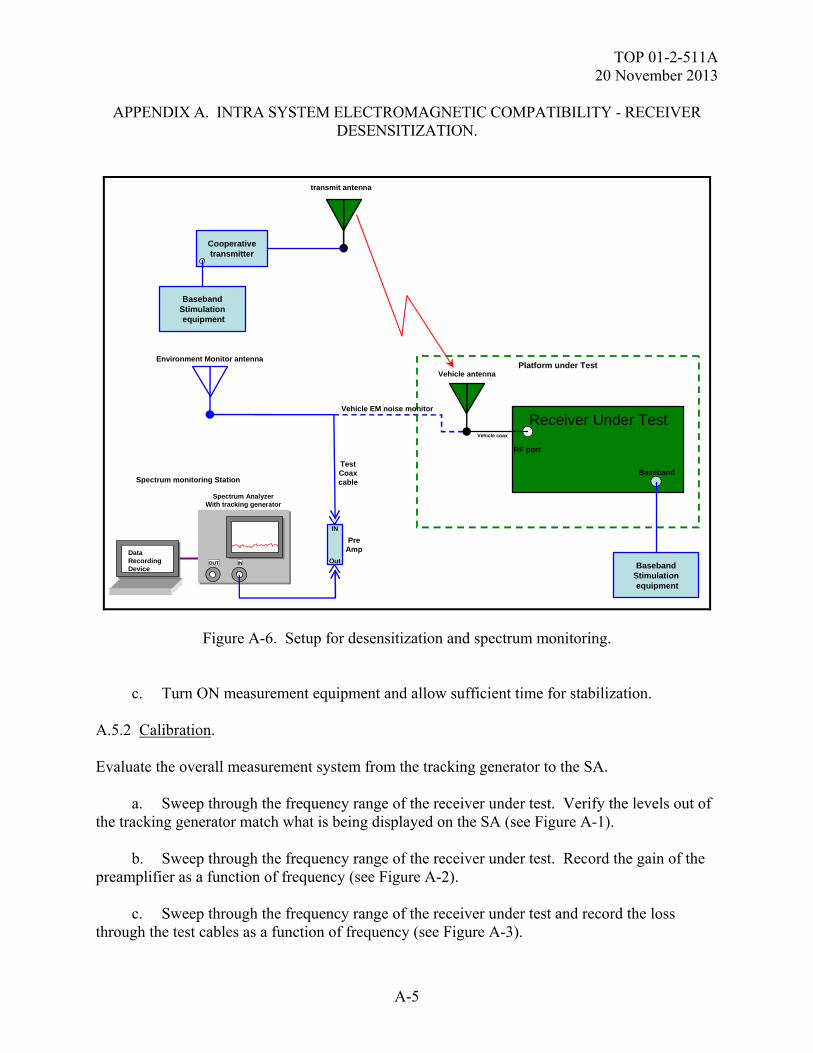
d. Sweep through the frequency range of the receiver under test and record the forward power as a function of frequency (see Figure A-4). Sweep though the same range and record the reverse power as a function of frequency (see Figure A-5). Insure that the unused port is terminated in 50 Ω’s. Calculate the voltage standing wave ratio (VSWR) versus frequency using the following equation:
10
10
10
11
10
11
dBmPdBmP
dBmPdBmP
reverseforward
reverseforward
VSWR
A.5.3 SUT Testing. Determine the desensitization of the receiver to the platform EM noise. a. From the monitor antenna observe the environmental ambient to ensure no major EM noise sources are present (see Figure A-6). b. From the antenna of the receiver under test measure the EM spectrum and record the spectrum (see Figure A-6). c. All Off. Turn on the receiver under test and allow sufficient time for stabilization. Leave the platform and all other system OFF. This will require operation of the receiver under test on battery power or other external to vehicle means. d. Establish a link with the transmitter. e. Adjust the transmitter level so that receive signal at the receiver under test is close to the noise level of the “all off” operating environment. Establish a baseband reference and record this reference the corresponding power level of the distant end transmitter for this ambient state. See examples below: Should set this level to the typical RSL. Not necessarily the radio sensitivity. Example: SINCGARS radio is typically about 9 dB more sensitive than it is expected to operate in a typical environment. If one bases the defense on the absolute receiver sensitivity, it may make the noise appear much more dramatic than what would actually be experienced in the field.
TOP 01-2-511A 20 November 2013
A-7
APPENDIX A. INTRA SYSTEM ELECTROMAGNETIC COMPATIBILITY - RECEIVER DESENSITIZATION.
A.5.4 Examples. a. All On. Install the receiver under test back into the platform. Turn ON the platform and all systems and allow them to stabilize. b. From the antenna of the receiver under test measure the EM spectrum and record the spectrum. c. Reconnect the receiver under test. d. Re-establish the baseband reference parameter determined above by increasing the distant end transmitter level. Record the baseband parameter and corresponding power levels. The difference between the all ON and all OFF (ambient) conditions, in dB, is the desensitization of the receiver. e. During the above process, the EM environment should be monitored via the remote monitoring antenna to ensure the environmental ambient remains somewhat constant. f. Cease transmitting. g. Examples: (1) For VHF single channel FM transceiver requires that a distant variable transmitter be set up with the appropriate FM deviation and modulated by a 1 kHz signal. At the receiver voice output a distortion analyzer is connected and the Signal, Noise, and Distortion (SINAD) on the 1 kHz signal is measured and set to obtain a 10 dB SINAD. (2) For SINCGARS, 16 Kbps data link having an 8% Bit Error Rate (BER) will be established from a nearby transmitter to a receiver that is installed in the platform. (3) For EPLRS establish a link and evaluate speed of service and message completion rate utilizing the lower tactical internet computer system as a stimulation source. NOTE: The test record should also call out frequency ranges and modes of operation that are commensurate with the radios being testing (i.e., SINCGARS should be tested at several frequencies across the band or utilize a full band hop set). If the bands are limited through frequency management, this should also be noted in the results and test set-up (e.g., SINCGARS was tested frequency hopping from 32-54 MHz due to frequency restrictions). Other radios should be tested at several frequencies across the bands of operation and in multiple modes: FM voice, TACSAT, SINCGARS waveforms, etc. h. All On. Install the receiver under test back into the platform. Turn ON the platform and all systems and allow them to stabilize.

TOP 01-2-511A 20 November 2013
A-8
APPENDIX A. INTRA SYSTEM ELECTROMAGNETIC COMPATIBILITY - RECEIVER DESENSITIZATION.
i. From the antenna of the receiver under test measure the EM spectrum and record the spectrum. j. Reconnect the receiver under test. k. Reestablish the baseband reference parameter determined above by increasing the distant end transmitter level. Record the baseband parameter and corresponding power levels. The difference between the all ON and all OFF (ambient) conditions, in dB, is the desensitization of the receiver. l. During the above process, the EM environment should be monitored via the remote monitoring antenna to ensure the environmental ambient remains somewhat constant. m. Cease transmitting. n. Apply corrections for cable loss, amplifier gain and any other losses/gains that are required and record the corrected values. o. Repeat steps a and n above for various combinations of equipment. A.6. DATA PRESENTATION. a. Manufacturer and Serial Numbers (SNs) of SUTs and test dates. b. Model, SN, and calibration dates of the test equipment. c. Results of operational verifications d. List of all test equipment, including model, SN, and calibration dates e. Results and photographs (if necessary) of physical inspections f. Test configuration parameters. g. Baseband stimulation technique and critical parameters used for each transceiver system. h. Ambient "state” baseline and all "state" baseband numbers and power levels.
TOP 01-2-511A 20 November 2013
A-9
APPENDIX A. INTRA SYSTEM ELECTROMAGNETIC COMPATIBILITY - RECEIVER DESENSITIZATION.
i. Data from the desensitization testing will be tabulated and presented as a table of desensitization in dB organized by victim radio and platform RF environmental state resulting from combinations of powered equipment. Ensure frequencies that are tested are reported and noted if limited by frequency management constraints A.7. DATA ANALYSIS. a. The data tables will be analyzed as to the effects of hosting and integration of the C4ISR communications equipment into the platform to determine if the effective communication range has been reduced and the applicable criteria have been met. b. A review of all pertinent data, all off ambient EM environment data/graphs, desensitization test data, modulation consideration and reasonable engineering judgment should be under taken to determine receiver degradation and impacts based on the link performance and reduction in range. c. A simple GO / NO-GO test is not acceptable. The data should be analyzed to determine the range reduction impact of the platform EM environment. Figure A-7 shows examples of a testing matrix and graphs that are required to adequately determine receiver degradation and affect on the system.
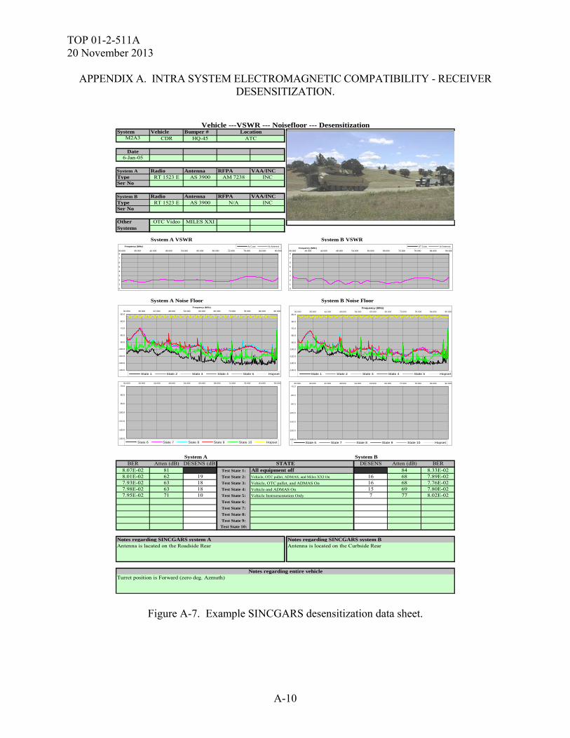
TOP 01-2-511A 20 November 2013
A-10
APPENDIX A. INTRA SYSTEM ELECTROMAGNETIC COMPATIBILITY - RECEIVER DESENSITIZATION.
System Vehicle Bumper #M2A3 CDR HQ-45
Date6-Jan-05
System A Radio Antenna RFPA VAA/INCType RT 1523 E AS 3900 AM 7238 INCSer No
System B Radio Antenna RFPA VAA/INCType RT 1523 E AS 3900 N/A INCSer No
Other OTC Video MILES XXISystems
System A VSWR System B VSWR
System A Noise Floor System B Noise Floor
System A System BBER Atten (dB) DESENS (dB) DESENS Atten (dB) BER
8.07E-02 81 Test State 1: 84 8.33E-028.01E-02 62 19 Test State 2: 16 68 7.89E-027.93E-02 63 18 Test State 3: 16 68 7.76E-027.98E-02 63 18 Test State 4: 15 69 7.80E-027.95E-02 71 10 Test State 5: 7 77 8.02E-02
Test State 6:
Test State 7:
Test State 8:
Test State 9:
Test State 10:
Notes regarding SINCGARS system A Notes regarding SINCGARS system BAntenna is lacated on the Roadside Rear Antenna is located on the Curbside Rear
Turret position is Forward (zero deg. Azmuth)
All equipment offVehicle, OTC pallet, ADMAS, and Miles XXI On
Vehicle, OTC pallet, and ADMAS On
Vehicle and ADMAS On
Vehicle Instrumentation Only
Vehicle ---VSWR --- Noisefloor --- Desensitization
STATE
LocationATC
Insert Picture Here
Notes regarding entire vehicle
-130.0
-120.0
-110.0
-100.0
-90.0
-80.0
-70.0
-60.0
-50.0
30.000 36.000 42.000 48.000 54.000 60.000 66.000 72.000 78.000 84.000 90.000
Frequency (MHz)
State 1 State 2 State 3 State 4 State 5 Hopset-130.0
-120.0
-110.0
-100.0
-90.0
-80.0
-70.0
-60.0
-50.0
30.000 36.000 42.000 48.000 54.000 60.000 66.000 72.000 78.000 84.000 90.000
Frequency (MHz)
State 1 State 2 State 3 State 4 State 5 Hopset
0
1
2
3
4
5
6
7
8
30.000 36.000 42.000 48.000 54.000 60.000 66.000 72.000 78.000 84.000 90.000
Frequency (MHz) At Coax At Antenna
0
1
2
3
4
5
6
7
8
30.000 36.000 42.000 48.000 54.000 60.000 66.000 72.000 78.000 84.000 90.000Frequency (MHz)
AT Coax At Antenna
-130.0
-120.0
-110.0
-100.0
-90.0
-80.0
-70.0
30.000 36.000 42.000 48.000 54.000 60.000 66.000 72.000 78.000 84.000 90.000
State 6 State 7 State 8 State 9 State 10 Hopset-130.0
-120.0
-110.0
-100.0
-90.0
-80.0
-70.0
30.000 36.000 42.000 48.000 54.000 60.000 66.000 72.000 78.000 84.000 90.000
State 6 State 7 State 8 State 9 State 10 Hopset
Figure A-7. Example SINCGARS desensitization data sheet.
TOP 01-2-511A 20 November 2013
B-1
APPENDIX B. EXTERNAL RF ELECTROMAGNETIC ENVIRONMENT (EME). B.1. APPLICABILITY. a. This test method is applicable to systems and platforms in accordance with the specification and MIL-STD-464C. This methodology can also be tailored for MIL-STD-461F Open Air Test Site (OATS) testing, as well as ADS-37A-PRF, and ATPD-2407 as specified in those documents. This method is to assess the operational survivability and identify susceptibilities to the SUT when exposed to its tactical operational EME. This Appendix is meant to act as a guide and is not a replacement for a test plan. Compliance shall be verified by system/platform-level test, analysis, or a combination thereof. b. To determine whether the system/platform’s operational performance requirements are met when subjected to the specified external RF EME. c. This subtest demonstrates survivability and compatibility of the SUT to EME from like systems, and external transmitters both hostile and non-hostile. B.2. REQUIREMENTS. a. The SUT shall be survivable and electromagnetically compatible when exposed to the specified external operational EM fields. The EM fields utilized in the External RF EME testing are derived from MIL-STD-464C (platform/system performance) as well as ADS-37A-PRF for aircraft. It is recommended that the modulations specified in applicable MIL-HDBK-235 document be utilized if a specific battlefield fielding is known in an effort to duplicate the modulations of those systems collocated. If this information is unknown ADS-37A-PRF can be utilized based on the system requirement for system or subsystem testing. Safety critical and mission critical system functions shall have a margin of at least 6 dB. Finally, experience has shown AM modulation to provide a majority of induced External RF EME effects and may be utilized if no modulation guidance is provided, or test time is not adequate to complete all modulations. b. To validate a system/platform operational performance requirements are met, the SUT must be tested under laboratory conditions where the SUT and test environment are controlled and while being operated during illumination. System-level testing of large platforms such as aircraft, tanks, and ships, is usually done in an open area test site. Ideally, the entire system should be illuminated uniformly at full threat for the most credible demonstration of hardness. Since the SUT under External RF EME test is evaluated as a victim of interference from the EME, operational modes of the SUT equipment and components are of great consequence in the assessment; therefore, the SUT will be tested while operationally manned, or with every mission essential function exercised during each illumination. c. The systems must operate and meet mission requirements after introduction of the EME.
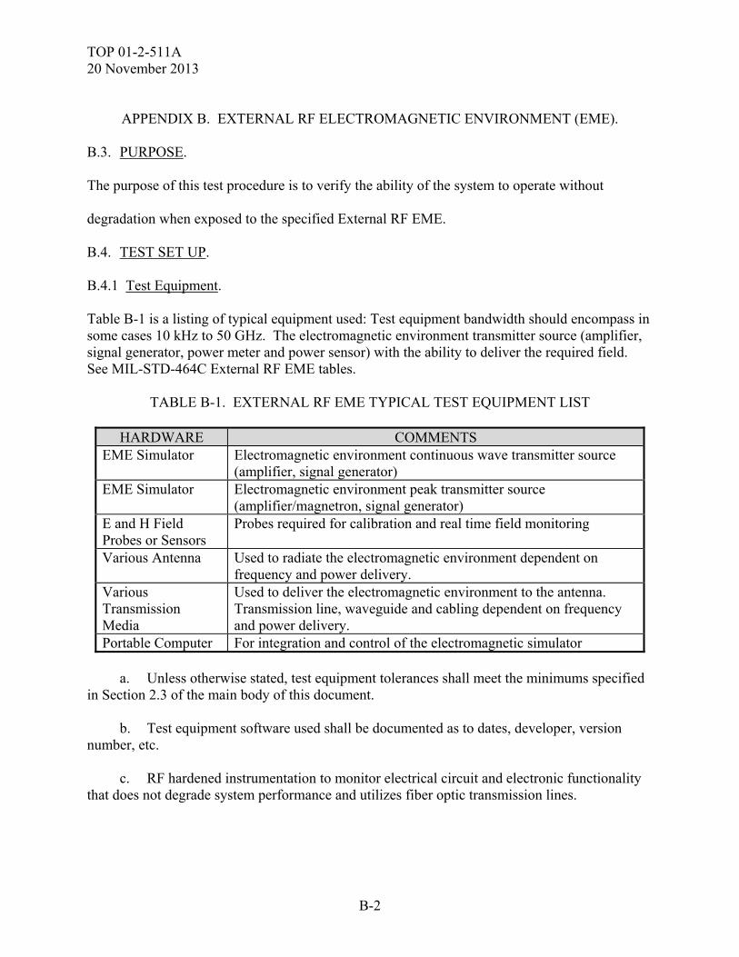
TOP 01-2-511A 20 November 2013
B-2
APPENDIX B. EXTERNAL RF ELECTROMAGNETIC ENVIRONMENT (EME).
B.3. PURPOSE.
The purpose of this test procedure is to verify the ability of the system to operate without
degradation when exposed to the specified External RF EME.
B.4. TEST SET UP. B.4.1 Test Equipment. Table B-1 is a listing of typical equipment used: Test equipment bandwidth should encompass in some cases 10 kHz to 50 GHz. The electromagnetic environment transmitter source (amplifier, signal generator, power meter and power sensor) with the ability to deliver the required field. See MIL-STD-464C External RF EME tables.
TABLE B-1. EXTERNAL RF EME TYPICAL TEST EQUIPMENT LIST
HARDWARE COMMENTS EME Simulator Electromagnetic environment continuous wave transmitter source
(amplifier, signal generator) EME Simulator Electromagnetic environment peak transmitter source
(amplifier/magnetron, signal generator) E and H Field Probes or Sensors
Probes required for calibration and real time field monitoring
Various Antenna Used to radiate the electromagnetic environment dependent on frequency and power delivery.
Various Transmission Media
Used to deliver the electromagnetic environment to the antenna. Transmission line, waveguide and cabling dependent on frequency and power delivery.
Portable Computer For integration and control of the electromagnetic simulator a. Unless otherwise stated, test equipment tolerances shall meet the minimums specified in Section 2.3 of the main body of this document. b. Test equipment software used shall be documented as to dates, developer, version number, etc. c. RF hardened instrumentation to monitor electrical circuit and electronic functionality that does not degrade system performance and utilizes fiber optic transmission lines.
TOP 01-2-511A 20 November 2013
B-3
APPENDIX B. EXTERNAL RF ELECTROMAGNETIC ENVIRONMENT (EME). B.4.1.2 SUT Instrumentation. SUT instrumentation is permissible, if the system's performance can be adequately verified but it shall not influence test results. SUT instrumentation may include the following: a. Cameras connected to monitors using fiber optic lines. The cameras may be placed within shielded enclosures or care taken to preclude electromagnetic interference. b. Test sets may be used to check out the SUT before and after each test event or may be required to operate and monitor the SUT during testing. If required during testing, test sets should be protected from the test environment and placed as far away from the source to target as possible. Any test set interface cabling should be well shielded and run to minimize coupling. B.4.2 Pre-Test Evaluation. a. Prior to the start of the test, the operators shall verify that all personnel are aware of the safety aspects associated with radiated fields and that all personnel have been briefed on this subject. The MPE of DODI 6055.11 will be strictly adhered to during the test. b. A pre-test evaluation will be performed to determine the primary current paths, ports of entry, test orientations and configurations, as well as the overall test conditions for the SUT. c. The SUT status should be verified and documented before testing, using baseline self-
test checks, system operational performance checks, and functional performance measures.
d. The pre-test analysis should also address the system inherent frequencies. These should include at a minimum; the system frequencies of transmission as well as associated modulation parameters, frequencies associated with data rates, computer processors and generator power. B.4.3 Setup. a. Figure B-1 depicts a typical EME transmission and antenna equipment block diagram for External RF EME testing. (1) The External RF EME transmission test facility is calibrated at a distance from the facility antenna to determine the power required to achieve the specified field strength. This measurement is a free field calibration. During the environmental illumination, the field strength is monitored at the specified mapping point (distance and height above ground). The antenna placement will be no lower than 1.5 - 2 meters above ground. The Source-To-Target(STT) distance from the test item will vary dependant on the frequency range, radiating antenna and SUT and should be measured from the nearest conducting surface of the SUT. This minimum distance shall be 1 meter and actual distance should be frequency and SUT size dependent. A real time field calibration measurement can be made if the SUT fits within a 2 meter test volume.
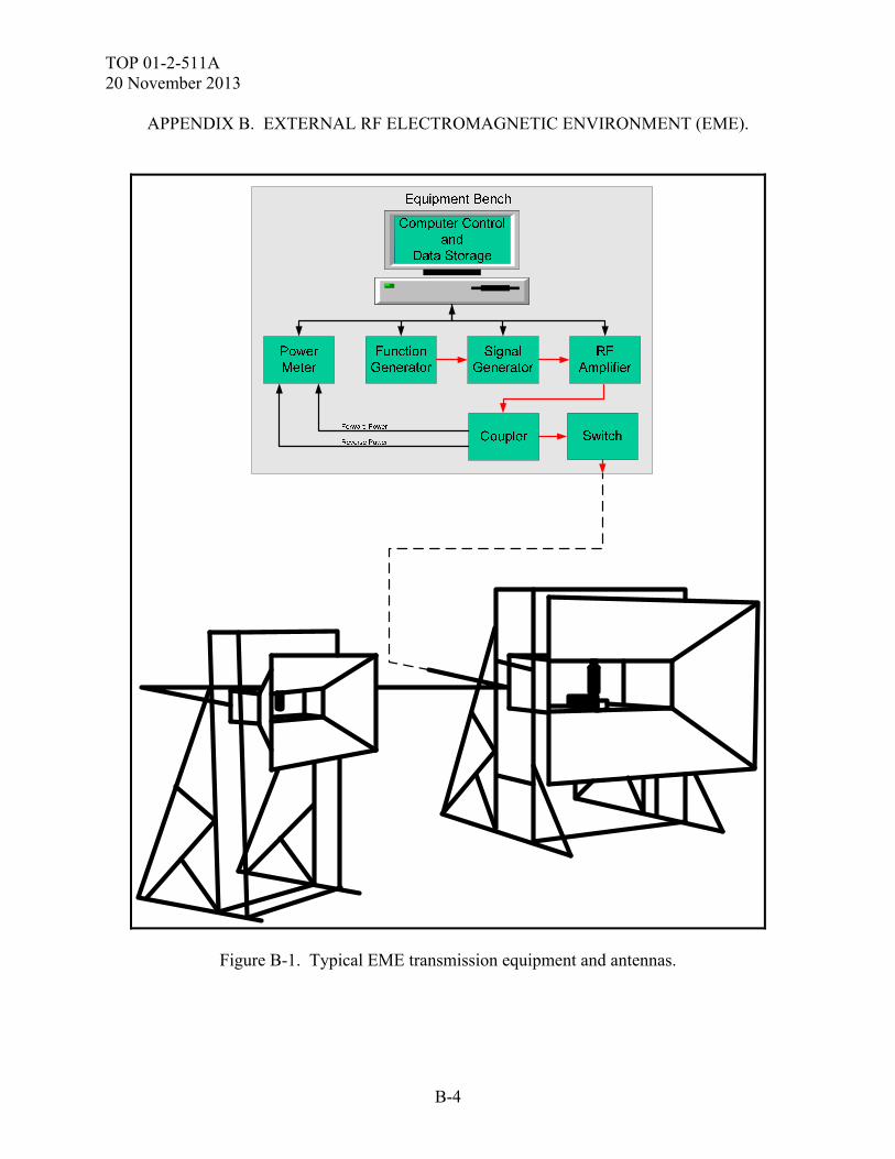
TOP 01-2-511A 20 November 2013
B-4
APPENDIX B. EXTERNAL RF ELECTROMAGNETIC ENVIRONMENT (EME).
Figure B-1. Typical EME transmission equipment and antennas.
TOP 01-2-511A 20 November 2013
B-5
APPENDIX B. EXTERNAL RF ELECTROMAGNETIC ENVIRONMENT (EME). (2) All EME illuminations will be IAW the test guidelines of MIL-STD-464C and can be tailored for MIL-STD-461F (small systems) IAW that document with the Army E3 board approval. (3) When the SUT is instrumented. Care must be taken to ensure that the installation of the data acquisition system, especially instrumentation to include power does not compromise or reduce the inherent shielding of the SUT. Fiber should be used where ever possible. (4) When there is no instrumentation or external system stimulation provided the SUT must be operated and manned by trained personnel during each illumination. (5) Throughout each illumination, the SUT configuration will be functional, in accordance with the SUT operating and mission function procedures. Problems with the EME simulator, SUT, or test set up will be identified, documented, and corrected if deemed detrimental to the test. B.5. TEST PROCEDURE. The specific test procedures will be conducted IAW the test plan. Any changes to these procedures will be noted in the test report. Safety procedures must be initiated in accordance with the test facility Standard Operating Procedures (SOP), the system SOP, and the SUT specific SAR. a. Sample test frequencies, field intensities (ground systems) and modulation used for testing are provided in Table B-2. A minimum of 100 frequencies is recommended (Table B-3 has a list of 279 sample frequencies (including the 100 HERO frequencies) to provide additional frequency coverage). Table B-4 has a list of sample peak pulse frequencies. Selected frequencies should be based on the tailoring documents (Army Aviation systems; ADS-37A, and TACOM systems; ATPD-2407).
TABLE B-2. SAMPLE EXTERNAL RF EME FREQUENCY LIST FOR GROUND SYSTEMS
FREQUENCY POLARIZATION MODULATIONELECTRIC FIELD
INTENSITY
(MHz) (POL) (MOD) (V rms /m)
3.03 V AM 103
4 V AM 103
5.28 V AM 103
6.06 V AM 103
8 V AM 103
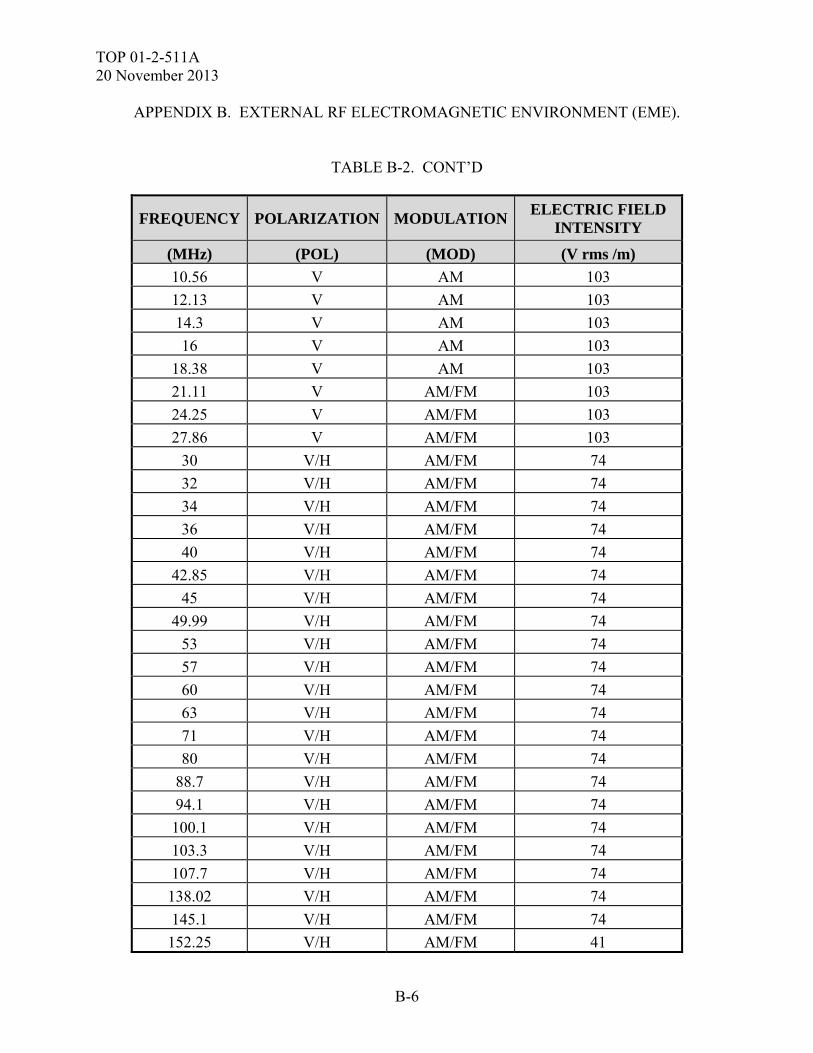
TOP 01-2-511A 20 November 2013
B-6
APPENDIX B. EXTERNAL RF ELECTROMAGNETIC ENVIRONMENT (EME).
TABLE B-2. CONT’D
FREQUENCY POLARIZATION MODULATIONELECTRIC FIELD
INTENSITY
(MHz) (POL) (MOD) (V rms /m)
10.56 V AM 103
12.13 V AM 103
14.3 V AM 103
16 V AM 103
18.38 V AM 103
21.11 V AM/FM 103
24.25 V AM/FM 103
27.86 V AM/FM 103
30 V/H AM/FM 74
32 V/H AM/FM 74
34 V/H AM/FM 74
36 V/H AM/FM 74
40 V/H AM/FM 74
42.85 V/H AM/FM 74
45 V/H AM/FM 74
49.99 V/H AM/FM 74
53 V/H AM/FM 74
57 V/H AM/FM 74
60 V/H AM/FM 74
63 V/H AM/FM 74
71 V/H AM/FM 74
80 V/H AM/FM 74
88.7 V/H AM/FM 74
94.1 V/H AM/FM 74
100.1 V/H AM/FM 74
103.3 V/H AM/FM 74
107.7 V/H AM/FM 74
138.02 V/H AM/FM 74
145.1 V/H AM/FM 74
152.25 V/H AM/FM 41
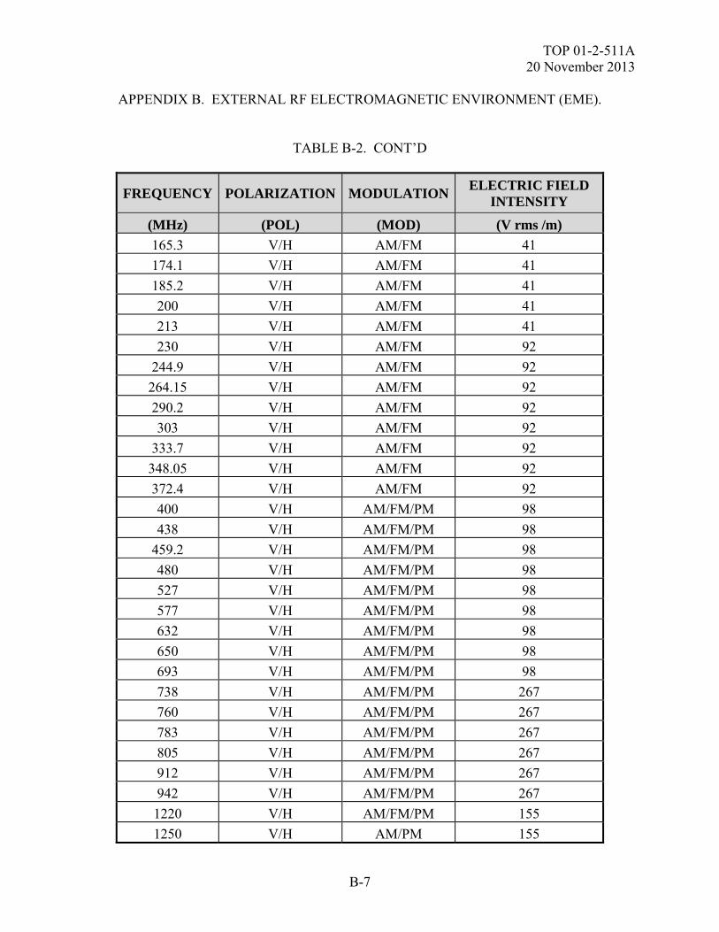
TOP 01-2-511A 20 November 2013
B-7
APPENDIX B. EXTERNAL RF ELECTROMAGNETIC ENVIRONMENT (EME).
TABLE B-2. CONT’D
FREQUENCY POLARIZATION MODULATIONELECTRIC FIELD
INTENSITY
(MHz) (POL) (MOD) (V rms /m)
165.3 V/H AM/FM 41
174.1 V/H AM/FM 41
185.2 V/H AM/FM 41
200 V/H AM/FM 41
213 V/H AM/FM 41
230 V/H AM/FM 92
244.9 V/H AM/FM 92
264.15 V/H AM/FM 92
290.2 V/H AM/FM 92
303 V/H AM/FM 92
333.7 V/H AM/FM 92
348.05 V/H AM/FM 92
372.4 V/H AM/FM 92
400 V/H AM/FM/PM 98
438 V/H AM/FM/PM 98
459.2 V/H AM/FM/PM 98
480 V/H AM/FM/PM 98
527 V/H AM/FM/PM 98
577 V/H AM/FM/PM 98
632 V/H AM/FM/PM 98
650 V/H AM/FM/PM 98
693 V/H AM/FM/PM 98
738 V/H AM/FM/PM 267
760 V/H AM/FM/PM 267
783 V/H AM/FM/PM 267
805 V/H AM/FM/PM 267
912 V/H AM/FM/PM 267
942 V/H AM/FM/PM 267
1220 V/H AM/FM/PM 155
1250 V/H AM/PM 155
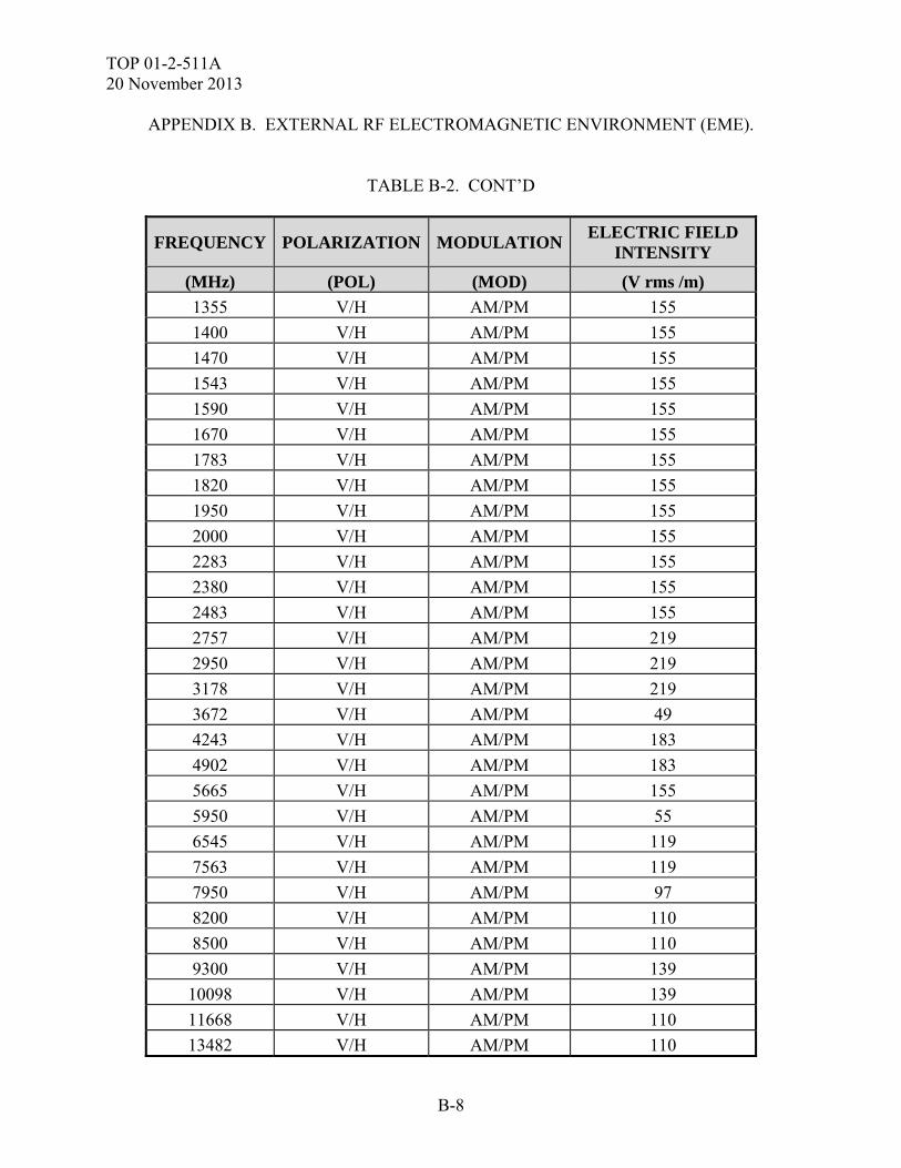
TOP 01-2-511A 20 November 2013
B-8
APPENDIX B. EXTERNAL RF ELECTROMAGNETIC ENVIRONMENT (EME).
TABLE B-2. CONT’D
FREQUENCY POLARIZATION MODULATIONELECTRIC FIELD
INTENSITY
(MHz) (POL) (MOD) (V rms /m)
1355 V/H AM/PM 155
1400 V/H AM/PM 155
1470 V/H AM/PM 155
1543 V/H AM/PM 155
1590 V/H AM/PM 155
1670 V/H AM/PM 155
1783 V/H AM/PM 155
1820 V/H AM/PM 155
1950 V/H AM/PM 155
2000 V/H AM/PM 155
2283 V/H AM/PM 155
2380 V/H AM/PM 155
2483 V/H AM/PM 155
2757 V/H AM/PM 219
2950 V/H AM/PM 219
3178 V/H AM/PM 219
3672 V/H AM/PM 49
4243 V/H AM/PM 183
4902 V/H AM/PM 183
5665 V/H AM/PM 155
5950 V/H AM/PM 55
6545 V/H AM/PM 119
7563 V/H AM/PM 119
7950 V/H AM/PM 97
8200 V/H AM/PM 110
8500 V/H AM/PM 110
9300 V/H AM/PM 139
10098 V/H AM/PM 139
11668 V/H AM/PM 110
13482 V/H AM/PM 110
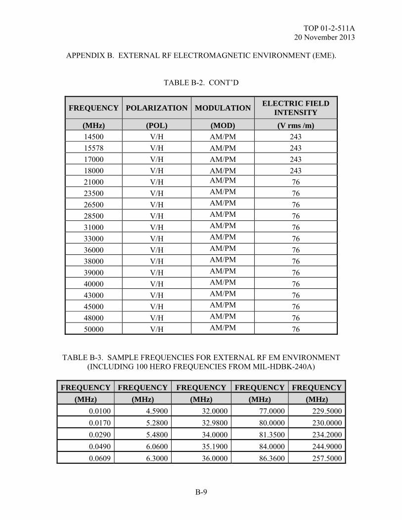
TOP 01-2-511A 20 November 2013
B-9
APPENDIX B. EXTERNAL RF ELECTROMAGNETIC ENVIRONMENT (EME).
TABLE B-2. CONT’D
FREQUENCY POLARIZATION MODULATIONELECTRIC FIELD
INTENSITY
(MHz) (POL) (MOD) (V rms /m)
14500 V/H AM/PM 243
15578 V/H AM/PM 243
17000 V/H AM/PM 243
18000 V/H AM/PM 243
21000 V/H AM/PM 76
23500 V/H AM/PM 76
26500 V/H AM/PM 76
28500 V/H AM/PM 76
31000 V/H AM/PM 76
33000 V/H AM/PM 76
36000 V/H AM/PM 76
38000 V/H AM/PM 76
39000 V/H AM/PM 76
40000 V/H AM/PM 76
43000 V/H AM/PM 76
45000 V/H AM/PM 76
48000 V/H AM/PM 76
50000 V/H AM/PM 76
TABLE B-3. SAMPLE FREQUENCIES FOR EXTERNAL RF EM ENVIRONMENT (INCLUDING 100 HERO FREQUENCIES FROM MIL-HDBK-240A)
FREQUENCY FREQUENCY FREQUENCY FREQUENCY FREQUENCY
(MHz) (MHz) (MHz) (MHz) (MHz)
0.0100 4.5900 32.0000 77.0000 229.5000
0.0170 5.2800 32.9800 80.0000 230.0000
0.0290 5.4800 34.0000 81.3500 234.2000
0.0490 6.0600 35.1900 84.0000 244.9000
0.0609 6.3000 36.0000 86.3600 257.5000
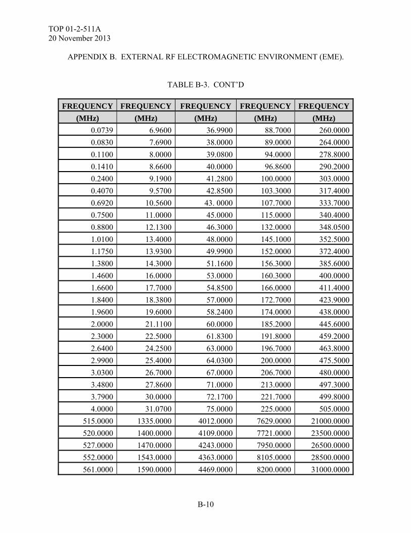
TOP 01-2-511A 20 November 2013
B-10
APPENDIX B. EXTERNAL RF ELECTROMAGNETIC ENVIRONMENT (EME).
TABLE B-3. CONT’D
FREQUENCY FREQUENCY FREQUENCY FREQUENCY FREQUENCY
(MHz) (MHz) (MHz) (MHz) (MHz)
0.0739 6.9600 36.9900 88.7000 260.0000
0.0830 7.6900 38.0000 89.0000 264.0000
0.1100 8.0000 39.0800 94.0000 278.8000
0.1410 8.6600 40.0000 96.8600 290.2000
0.2400 9.1900 41.2800 100.0000 303.0000
0.4070 9.5700 42.8500 103.3000 317.4000
0.6920 10.5600 43. 0000 107.7000 333.7000
0.7500 11.0000 45.0000 115.0000 340.4000
0.8800 12.1300 46.3000 132.0000 348.0500
1.0100 13.4000 48.0000 145.1000 352.5000
1.1750 13.9300 49.9900 152.0000 372.4000
1.3800 14.3000 51.1600 156.3000 385.6000
1.4600 16.0000 53.0000 160.3000 400.0000
1.6600 17.7000 54.8500 166.0000 411.4000
1.8400 18.3800 57.0000 172.7000 423.9000
1.9600 19.6000 58.2400 174.0000 438.0000
2.0000 21.1100 60.0000 185.2000 445.6000
2.3000 22.5000 61.8300 191.8000 459.2000
2.6400 24.2500 63.0000 196.7000 463.8000
2.9900 25.4000 64.0300 200.0000 475.5000
3.0300 26.7000 67.0000 206.7000 480.0000
3.4800 27.8600 71.0000 213.0000 497.3000
3.7900 30.0000 72.1700 221.7000 499.8000
4.0000 31.0700 75.0000 225.0000 505.0000
515.0000 1335.0000 4012.0000 7629.0000 21000.0000
520.0000 1400.0000 4109.0000 7721.0000 23500.0000
527.0000 1470.0000 4243.0000 7950.0000 26500.0000
552.0000 1543.0000 4363.0000 8105.0000 28500.0000
561.0000 1590.0000 4469.0000 8200.0000 31000.0000
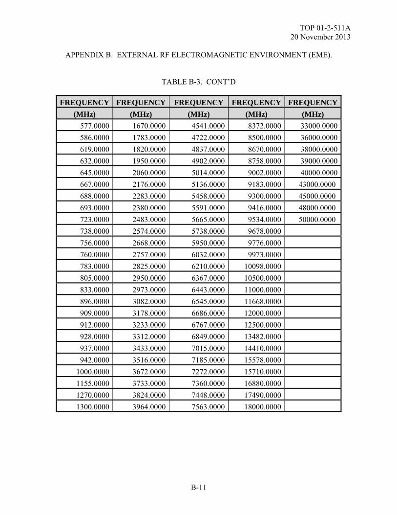
TOP 01-2-511A 20 November 2013
B-11
APPENDIX B. EXTERNAL RF ELECTROMAGNETIC ENVIRONMENT (EME).
TABLE B-3. CONT’D
FREQUENCY FREQUENCY FREQUENCY FREQUENCY FREQUENCY
(MHz) (MHz) (MHz) (MHz) (MHz)
577.0000 1670.0000 4541.0000 8372.0000 33000.0000
586.0000 1783.0000 4722.0000 8500.0000 36000.0000
619.0000 1820.0000 4837.0000 8670.0000 38000.0000
632.0000 1950.0000 4902.0000 8758.0000 39000.0000
645.0000 2060.0000 5014.0000 9002.0000 40000.0000
667.0000 2176.0000 5136.0000 9183.0000 43000.0000
688.0000 2283.0000 5458.0000 9300.0000 45000.0000
693.0000 2380.0000 5591.0000 9416.0000 48000.0000
723.0000 2483.0000 5665.0000 9534.0000 50000.0000
738.0000 2574.0000 5738.0000 9678.0000
756.0000 2668.0000 5950.0000 9776.0000
760.0000 2757.0000 6032.0000 9973.0000
783.0000 2825.0000 6210.0000 10098.0000
805.0000 2950.0000 6367.0000 10500.0000
833.0000 2973.0000 6443.0000 11000.0000
896.0000 3082.0000 6545.0000 11668.0000
909.0000 3178.0000 6686.0000 12000.0000
912.0000 3233.0000 6767.0000 12500.0000
928.0000 3312.0000 6849.0000 13482.0000
937.0000 3433.0000 7015.0000 14410.0000
942.0000 3516.0000 7185.0000 15578.0000
1000.0000 3672.0000 7272.0000 15710.0000
1155.0000 3733.0000 7360.0000 16880.0000
1270.0000 3824.0000 7448.0000 17490.0000
1300.0000 3964.0000 7563.0000 18000.0000
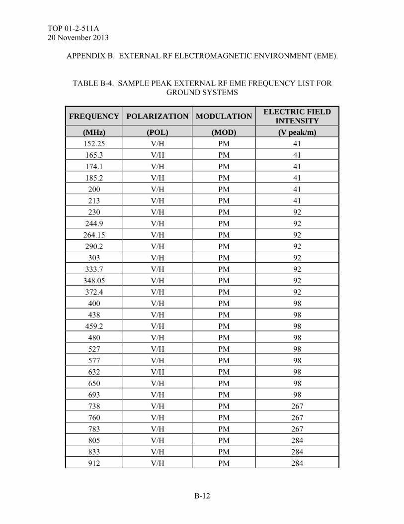
TOP 01-2-511A 20 November 2013
B-12
APPENDIX B. EXTERNAL RF ELECTROMAGNETIC ENVIRONMENT (EME).
TABLE B-4. SAMPLE PEAK EXTERNAL RF EME FREQUENCY LIST FOR GROUND SYSTEMS
FREQUENCY POLARIZATION MODULATIONELECTRIC FIELD
INTENSITY
(MHz) (POL) (MOD) (V peak/m)
152.25 V/H PM 41
165.3 V/H PM 41
174.1 V/H PM 41
185.2 V/H PM 41
200 V/H PM 41
213 V/H PM 41
230 V/H PM 92
244.9 V/H PM 92
264.15 V/H PM 92
290.2 V/H PM 92
303 V/H PM 92
333.7 V/H PM 92
348.05 V/H PM 92
372.4 V/H PM 92
400 V/H PM 98
438 V/H PM 98
459.2 V/H PM 98
480 V/H PM 98
527 V/H PM 98
577 V/H PM 98
632 V/H PM 98
650 V/H PM 98
693 V/H PM 98
738 V/H PM 267
760 V/H PM 267
783 V/H PM 267
805 V/H PM 284
833 V/H PM 284
912 V/H PM 284
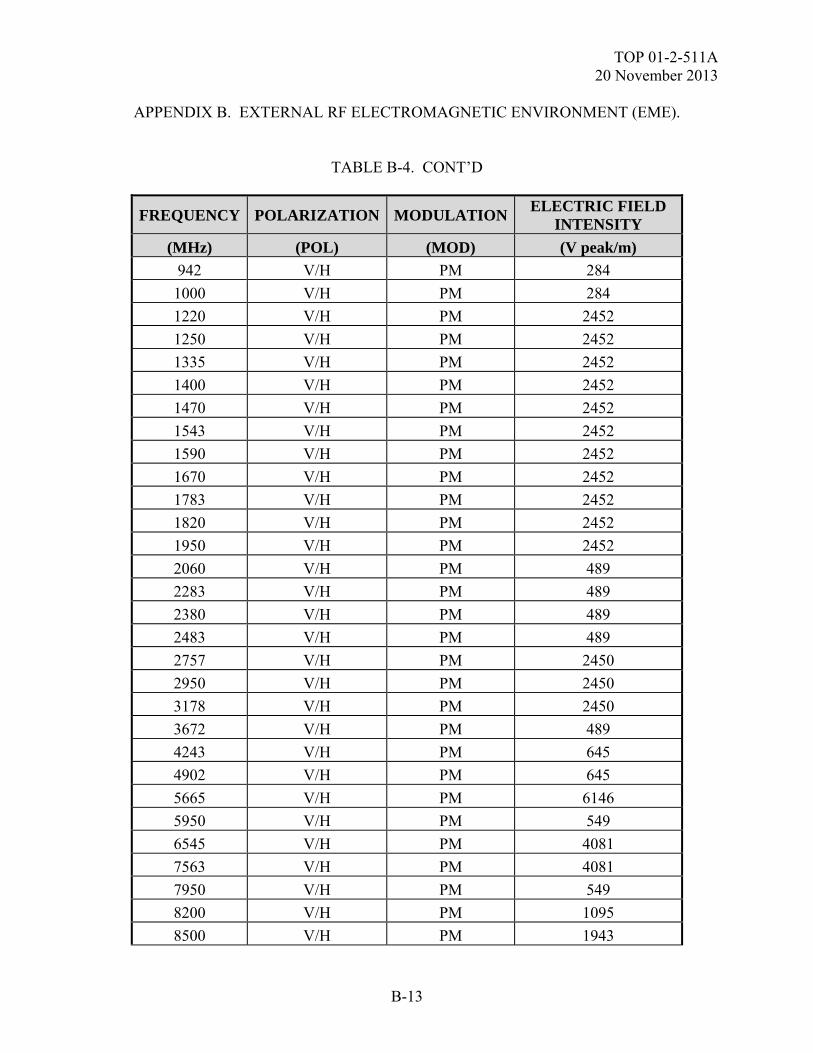
TOP 01-2-511A 20 November 2013
B-13
APPENDIX B. EXTERNAL RF ELECTROMAGNETIC ENVIRONMENT (EME).
TABLE B-4. CONT’D
FREQUENCY POLARIZATION MODULATIONELECTRIC FIELD
INTENSITY
(MHz) (POL) (MOD) (V peak/m)
942 V/H PM 284
1000 V/H PM 284
1220 V/H PM 2452
1250 V/H PM 2452
1335 V/H PM 2452
1400 V/H PM 2452
1470 V/H PM 2452
1543 V/H PM 2452
1590 V/H PM 2452
1670 V/H PM 2452
1783 V/H PM 2452
1820 V/H PM 2452
1950 V/H PM 2452
2060 V/H PM 489
2283 V/H PM 489
2380 V/H PM 489
2483 V/H PM 489
2757 V/H PM 2450
2950 V/H PM 2450
3178 V/H PM 2450
3672 V/H PM 489
4243 V/H PM 645
4902 V/H PM 645
5665 V/H PM 6146
5950 V/H PM 549
6545 V/H PM 4081
7563 V/H PM 4081
7950 V/H PM 549
8200 V/H PM 1095
8500 V/H PM 1943
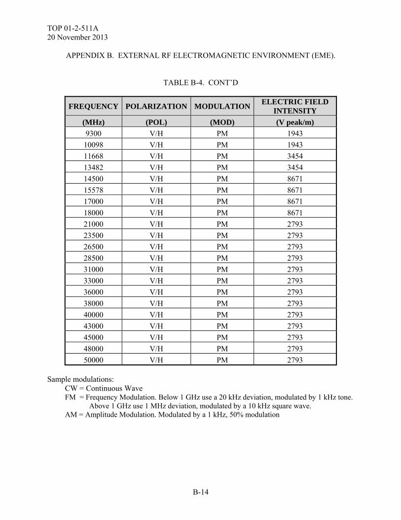
TOP 01-2-511A 20 November 2013
B-14
APPENDIX B. EXTERNAL RF ELECTROMAGNETIC ENVIRONMENT (EME).
TABLE B-4. CONT’D
FREQUENCY POLARIZATION MODULATIONELECTRIC FIELD
INTENSITY
(MHz) (POL) (MOD) (V peak/m)
9300 V/H PM 1943
10098 V/H PM 1943
11668 V/H PM 3454
13482 V/H PM 3454
14500 V/H PM 8671
15578 V/H PM 8671
17000 V/H PM 8671
18000 V/H PM 8671
21000 V/H PM 2793
23500 V/H PM 2793
26500 V/H PM 2793
28500 V/H PM 2793
31000 V/H PM 2793
33000 V/H PM 2793
36000 V/H PM 2793
38000 V/H PM 2793
40000 V/H PM 2793
43000 V/H PM 2793
45000 V/H PM 2793
48000 V/H PM 2793
50000 V/H PM 2793 Sample modulations: CW = Continuous Wave FM = Frequency Modulation. Below 1 GHz use a 20 kHz deviation, modulated by 1 kHz tone. Above 1 GHz use 1 MHz deviation, modulated by a 10 kHz square wave. AM = Amplitude Modulation. Modulated by a 1 kHz, 50% modulation
TOP 01-2-511A 20 November 2013
B-15
APPENDIX B. EXTERNAL RF ELECTROMAGNETIC ENVIRONMENT (EME). b. The SUT will be exposed at critical orientations taking into consideration placement of communication, electronics, harness cabling, shielded apertures and points of entry (POE). At least two antenna placement aspect angles should be considered for a very small system (less than 1 m X 1 m). All other items should have a minimum of four 90 degree aspect angles. Also, a 45 degree aspect angle should be considered dependent on the worse case orientation for POEs. Additionally, any system with a turret or rotating gun should also be exercised and considered in the test item orientations. c. The following sequence will be observed for each test illumination: (1) The environment will be adjusted to generate a peak pulsed power EME (as required for aviation and shipboard operations, as well as ground equipment), continuous wave (CW), or modulated field. Experience has shown AM modulation to provide a majority of induced External RF EME effects. It is suggested to utilize the modulations for the applicable class of systems as specified in MIL-HDBK-235/1C. Transmitter power will be increased until the criterion field is reached, or facility limitation is reached. (2) If an anomaly or effect is observed an additional test exposure will be conducted to ensure that the EME was the cause of the effect. Observed data as well as real time SUT instrumentation data will be collected for every test illumination either by soft or hard copy. (3) When susceptibility indications are noted in the SUT operation, a threshold level shall be determined where the susceptible condition is no longer present. Thresholds of susceptibility shall be determined as follows and described in the test report: (a) When a susceptibility condition is detected, reduce the interference signal until the SUT recovers. (b) Reduce the interference signal by an additional 6 dB. (c) Gradually increase the interference signal until the susceptibility condition reoccurs. The resulting level is the threshold of susceptibility. (d) Record this level, frequency range of occurrence, frequency and level of greatest susceptibility, and other test parameters, as applicable. (e) Procedures will be repeated for each test frequency, polarization, modulation, and test item orientation. (f) Personnel exposure limits averaging period should be taken into account for dwell times during testing. The illumination period that expose personnel to hazardous fields should not exceed three minutes or the direction of DODI 6055.11
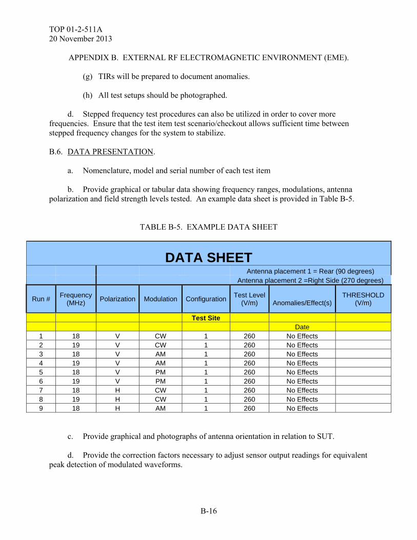
TOP 01-2-511A 20 November 2013
B-16
APPENDIX B. EXTERNAL RF ELECTROMAGNETIC ENVIRONMENT (EME). (g) TIRs will be prepared to document anomalies. (h) All test setups should be photographed. d. Stepped frequency test procedures can also be utilized in order to cover more frequencies. Ensure that the test item test scenario/checkout allows sufficient time between stepped frequency changes for the system to stabilize. B.6. DATA PRESENTATION. a. Nomenclature, model and serial number of each test item b. Provide graphical or tabular data showing frequency ranges, modulations, antenna polarization and field strength levels tested. An example data sheet is provided in Table B-5.
TABLE B-5. EXAMPLE DATA SHEET
DATA SHEET Antenna placement 1 = Rear (90 degrees) Antenna placement 2 =Right Side (270 degrees)
Run # Frequency
(MHz) Polarization Modulation Configuration
Test Level(V/m)
Anomalies/Effect(s)
THRESHOLD (V/m)
Test Site Date 1 18 V CW 1 260 No Effects 2 19 V CW 1 260 No Effects 3 18 V AM 1 260 No Effects 4 19 V AM 1 260 No Effects 5 18 V PM 1 260 No Effects 6 19 V PM 1 260 No Effects 7 18 H CW 1 260 No Effects 8 19 H CW 1 260 No Effects 9 18 H AM 1 260 No Effects
c. Provide graphical and photographs of antenna orientation in relation to SUT. d. Provide the correction factors necessary to adjust sensor output readings for equivalent peak detection of modulated waveforms.
TOP 01-2-511A 20 November 2013
B-17
APPENDIX B. EXTERNAL RF ELECTROMAGNETIC ENVIRONMENT (EME). e. Provide graphs or tables listing any susceptibility thresholds that were determined along with their associated frequencies. f. Provide diagrams and photographs showing actual equipment setup. g. Calibration date and serial/model numbers of test/data acquisition instrumentation. B.7. DATA ANALYSIS. a. Data from the External RF EME test environment measurements will be scored against the criteria levels, to determine the extent to which the test environment criteria and safety margins (if applicable), as well as equipment specification were met. Deficiencies will be identified and discussed with respect to criteria compliance and the potential for encountering the same electromagnetic environment. Failures or degradation resulting in SUT performance outside specifications, will be addressed with regards to causes, test level at which they occurred, allowable downtime, and mission impact. The test system configuration will be evaluated against the expected production configuration and the differences documented. Corrective hardening and/or mitigation recommendations will be developed and documented. b. The environment data will be compared and evaluated against the systems required criteria. Facility criteria compliance should be addressed to ensure that any deficiencies are addressed either by increasing the amplitude of the environment, or application of direct drive techniques for compensation.

TOP 01-2-511A 20 November 2013
B-18
(This page is intentionally blank.)
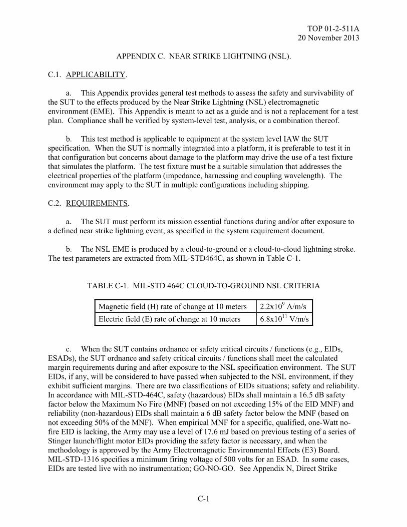
TOP 01-2-511A 20 November 2013
C-1
APPENDIX C. NEAR STRIKE LIGHTNING (NSL). C.1. APPLICABILITY. a. This Appendix provides general test methods to assess the safety and survivability of the SUT to the effects produced by the Near Strike Lightning (NSL) electromagnetic environment (EME). This Appendix is meant to act as a guide and is not a replacement for a test plan. Compliance shall be verified by system-level test, analysis, or a combination thereof. b. This test method is applicable to equipment at the system level IAW the SUT specification. When the SUT is normally integrated into a platform, it is preferable to test it in that configuration but concerns about damage to the platform may drive the use of a test fixture that simulates the platform. The test fixture must be a suitable simulation that addresses the electrical properties of the platform (impedance, harnessing and coupling wavelength). The environment may apply to the SUT in multiple configurations including shipping. C.2. REQUIREMENTS. a. The SUT must perform its mission essential functions during and/or after exposure to a defined near strike lightning event, as specified in the system requirement document. b. The NSL EME is produced by a cloud-to-ground or a cloud-to-cloud lightning stroke. The test parameters are extracted from MIL-STD464C, as shown in Table C-1.
TABLE C-1. MIL-STD 464C CLOUD-TO-GROUND NSL CRITERIA
Magnetic field (H) rate of change at 10 meters 2.2x10⁹ A/m/s
Electric field (E) rate of change at 10 meters 6.8x10¹¹ V/m/s
c. When the SUT contains ordnance or safety critical circuits / functions (e.g., EIDs, ESADs), the SUT ordnance and safety critical circuits / functions shall meet the calculated margin requirements during and after exposure to the NSL specification environment. The SUT EIDs, if any, will be considered to have passed when subjected to the NSL environment, if they exhibit sufficient margins. There are two classifications of EIDs situations; safety and reliability. In accordance with MIL-STD-464C, safety (hazardous) EIDs shall maintain a 16.5 dB safety factor below the Maximum No Fire (MNF) (based on not exceeding 15% of the EID MNF) and reliability (non-hazardous) EIDs shall maintain a 6 dB safety factor below the MNF (based on not exceeding 50% of the MNF). When empirical MNF for a specific, qualified, one-Watt no-fire EID is lacking, the Army may use a level of 17.6 mJ based on previous testing of a series of Stinger launch/flight motor EIDs providing the safety factor is necessary, and when the methodology is approved by the Army Electromagnetic Environmental Effects (E3) Board. MIL-STD-1316 specifies a minimum firing voltage of 500 volts for an ESAD. In some cases, EIDs are tested live with no instrumentation; GO-NO-GO. See Appendix N, Direct Strike
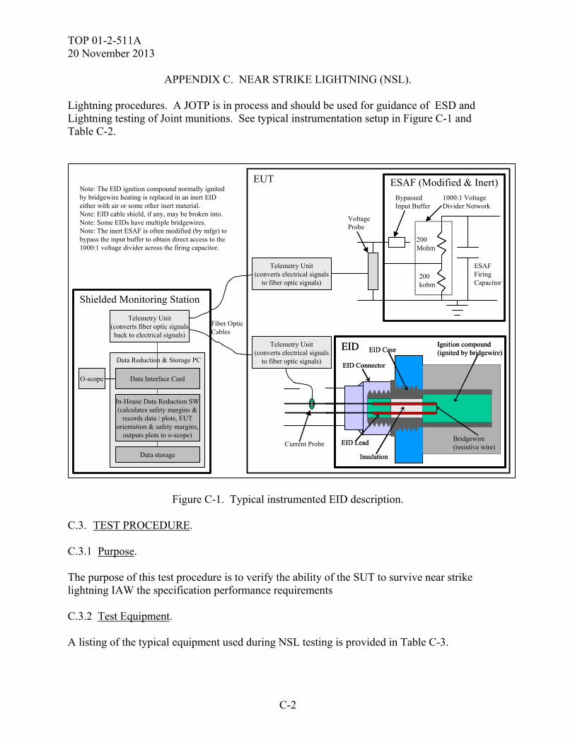
TOP 01-2-511A 20 November 2013
C-2
APPENDIX C. NEAR STRIKE LIGHTNING (NSL). Lightning procedures. A JOTP is in process and should be used for guidance of ESD and Lightning testing of Joint munitions. See typical instrumentation setup in Figure C-1 and Table C-2.
Shielded Monitoring Station
Fiber OpticCables
Data Reduction & Storage PC
Data Interface Card
In-House Data Reduction SW(calculates safety margins &
records data / plots, EUTorientation & safety margins,
outputs plots to o-scope)
Data storage
Note: The EID ignition compound normally ignitedby bridgewire heating is replaced in an inert EIDeither with air or some other inert material.Note: EID cable shield, if any, may be broken into.Note: Some EIDs have multiple bridgewires.Note: The inert ESAF is often modified (by mfgr) tobypass the input buffer to obtain direct access to the1000:1 voltage divider across the firing capacitor.
EID
Bridgewire(resistive wire)
EID Connector
Insulation
EID Lead
EID CaseIgnition compound(ignited by bridgewire)
EID
Bridgewire(resistive wire)
EID Connector
Insulation
EID Lead
EID CaseIgnition compound(ignited by bridgewire)
ESAF (Modified & Inert)
ESAFFiringCapacitor
BypassedInput Buffer
200Mohm
200kohm
1000:1 VoltageDivider Network
Current Probe
VoltageProbe
Telemetry Unit(converts electrical signals
to fiber optic signals)
Telemetry Unit(converts electrical signals
to fiber optic signals)
EUT
O-scope
Telemetry Unit(converts fiber optic signalsback to electrical signals)
Figure C-1. Typical instrumented EID description. C.3. TEST PROCEDURE. C.3.1 Purpose. The purpose of this test procedure is to verify the ability of the SUT to survive near strike lightning IAW the specification performance requirements C.3.2 Test Equipment. A listing of the typical equipment used during NSL testing is provided in Table C-3.
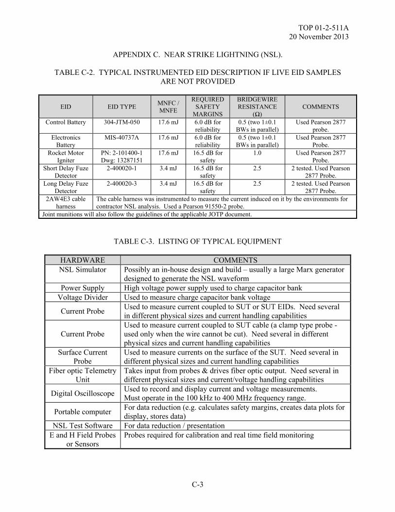
TOP 01-2-511A 20 November 2013
C-3
APPENDIX C. NEAR STRIKE LIGHTNING (NSL).
TABLE C-2. TYPICAL INSTRUMENTED EID DESCRIPTION IF LIVE EID SAMPLES ARE NOT PROVIDED
EID EID TYPE MNFC / MNFE
REQUIRED SAFETY
MARGINS
BRIDGEWIRE RESISTANCE
(Ω) COMMENTS
Control Battery 304-JTM-050 17.6 mJ 6.0 dB for reliability
0.5 (two 1±0.1 BWs in parallel)
Used Pearson 2877 probe.
Electronics Battery
MIS-40737A 17.6 mJ 6.0 dB for reliability
0.5 (two 1±0.1 BWs in parallel)
Used Pearson 2877 Probe.
Rocket Motor Igniter
PN: 2-101400-1 Dwg: 13287151
17.6 mJ 16.5 dB for safety
1.0 Used Pearson 2877 Probe.
Short Delay Fuze Detector
2-400020-1 3.4 mJ 16.5 dB for safety
2.5 2 tested. Used Pearson 2877 Probe.
Long Delay Fuze Detector
2-400020-3 3.4 mJ 16.5 dB for safety
2.5 2 tested. Used Pearson 2877 Probe.
2AW4E3 cable harness
The cable harness was instrumented to measure the current induced on it by the environments for contractor NSL analysis. Used a Pearson 91550-2 probe.
Joint munitions will also follow the guidelines of the applicable JOTP document.
TABLE C-3. LISTING OF TYPICAL EQUIPMENT
HARDWARE COMMENTS NSL Simulator Possibly an in-house design and build – usually a large Marx generator
designed to generate the NSL waveform Power Supply High voltage power supply used to charge capacitor bank
Voltage Divider Used to measure charge capacitor bank voltage
Current Probe Used to measure current coupled to SUT or SUT EIDs. Need several in different physical sizes and current handling capabilities
Current Probe Used to measure current coupled to SUT cable (a clamp type probe - used only when the wire cannot be cut). Need several in different physical sizes and current handling capabilities
Surface Current Probe
Used to measure currents on the surface of the SUT. Need several in different physical sizes and current handling capabilities
Fiber optic Telemetry Unit
Takes input from probes & drives fiber optic output. Need several in different physical sizes and current/voltage handling capabilities
Digital Oscilloscope Used to record and display current and voltage measurements. Must operate in the 100 kHz to 400 MHz frequency range.
Portable computer For data reduction (e.g. calculates safety margins, creates data plots for display, stores data)
NSL Test Software For data reduction / presentation E and H Field Probes
or Sensors Probes required for calibration and real time field monitoring
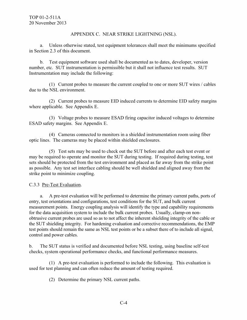
TOP 01-2-511A 20 November 2013
C-4
APPENDIX C. NEAR STRIKE LIGHTNING (NSL).
a. Unless otherwise stated, test equipment tolerances shall meet the minimums specified in Section 2.3 of this document. b. Test equipment software used shall be documented as to dates, developer, version number, etc. SUT instrumentation is permissible but it shall not influence test results. SUT Instrumentation may include the following: (1) Current probes to measure the current coupled to one or more SUT wires / cables due to the NSL environment. (2) Current probes to measure EID induced currents to determine EID safety margins where applicable. See Appendix E. (3) Voltage probes to measure ESAD firing capacitor induced voltages to determine ESAD safety margins. See Appendix E. (4) Cameras connected to monitors in a shielded instrumentation room using fiber optic lines. The cameras may be placed within shielded enclosures. (5) Test sets may be used to check out the SUT before and after each test event or may be required to operate and monitor the SUT during testing. If required during testing, test sets should be protected from the test environment and placed as far away from the strike point as possible. Any test set interface cabling should be well shielded and aligned away from the strike point to minimize coupling. C.3.3 Pre-Test Evaluation. a. A pre-test evaluation will be performed to determine the primary current paths, ports of entry, test orientations and configurations, test conditions for the SUT, and bulk current measurement points. Energy coupling analysis will identify the type and capability requirements for the data acquisition system to include the bulk current probes. Usually, clamp-on non-obtrusive current probes are used so as to not affect the inherent shielding integrity of the cable or the SUT shielding integrity. For hardening evaluation and corrective recommendations, the EMP test points should remain the same as NSL test points or be a subset there of to include all signal, control and power cables. b. The SUT status is verified and documented before NSL testing, using baseline self-test checks, system operational performance checks, and functional performance measures. (1) A pre-test evaluation is performed to include the following. This evaluation is used for test planning and can often reduce the amount of testing required. (2) Determine the primary NSL current paths.
TOP 01-2-511A 20 November 2013
C-5
APPENDIX C. NEAR STRIKE LIGHTNING (NSL). (3) Determine the most / least susceptible SUT configurations. (4) Determine the most / least susceptible SUT modes of operation. (5) Determine the probable Ports of Entry (POEs). (6) Determine the bulk current measurement points. (7) Perform an energy coupling analysis to identify the type and capability requirements for the data acquisition system. Usually, clamp-on non-obtrusive current probes are used to not affect the inherent shielding integrity of the cable or the SUT shielding integrity. (8) Determine critical SUT data required to be instrumented and monitored. (9) Determine which EIDs are to be instrumented and measured and how. (10) Determine SUT/platform critical functions and circuits. (11) Determine SUT NSL protection features and their predicted performance and whether they are repairable or replaceable. (12) Determine verification and pass/fail criteria and required margins. (13) Determine the SUT operating and check-out procedures. c. Pre-existing analyses and test data from previous tests may be evaluated and incorporated into the test planning and pre-test analysis in order to enhance and reduce the scope of the new testing. C.4. TEST SETUP. Test setups vary. Some typical test setups and photographs are shown in Figures C-2 through C-4. Following are general / typical test setup guidelines. a. The NSL environment is generated by discharging the energy in the capacitor bank through low resistance cables onto the NSL discharge point. b. Fast response current probes are used to monitor current and to measure the test energy. Telemetry units are used to convert the electrical signals to optical signals and transmit them over fiber optic lines to a receiver in a shielded area where they are converted back to electrical signals, processed, observed (monitored on a digitizing oscilloscope), and recorded on a PC laptop for data reduction. Test data reduction software extracts the desired test parameters, calculates the EID / ESAF safety margins where applicable, plots the data and creates plots.
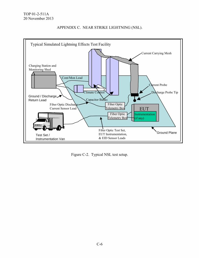
TOP 01-2-511A 20 November 2013
C-6
APPENDIX C. NEAR STRIKE LIGHTNING (NSL).
Charging Station andMonitoring Shed
Climate Control Discharge Probe Tip
Capacitor Banks
Current Carrying Mesh
Current Probe
Instrumentation(if any)
EUT
Cont/Mon Lead
Fiber Optic DischargeCurrent Sensor Lead
Typical Simulated Lightning Effects Test Facility
Fiber Optic Test Set,EUT Instrumentation,& EID Sensor Leads
Test Set / Instrumentation Van
Ground Plane
Ground / DischargeReturn Lead
Fiber OpticTelemetry Box
Fiber OpticTelemetry Box
Figure C-2. Typical NSL test setup.
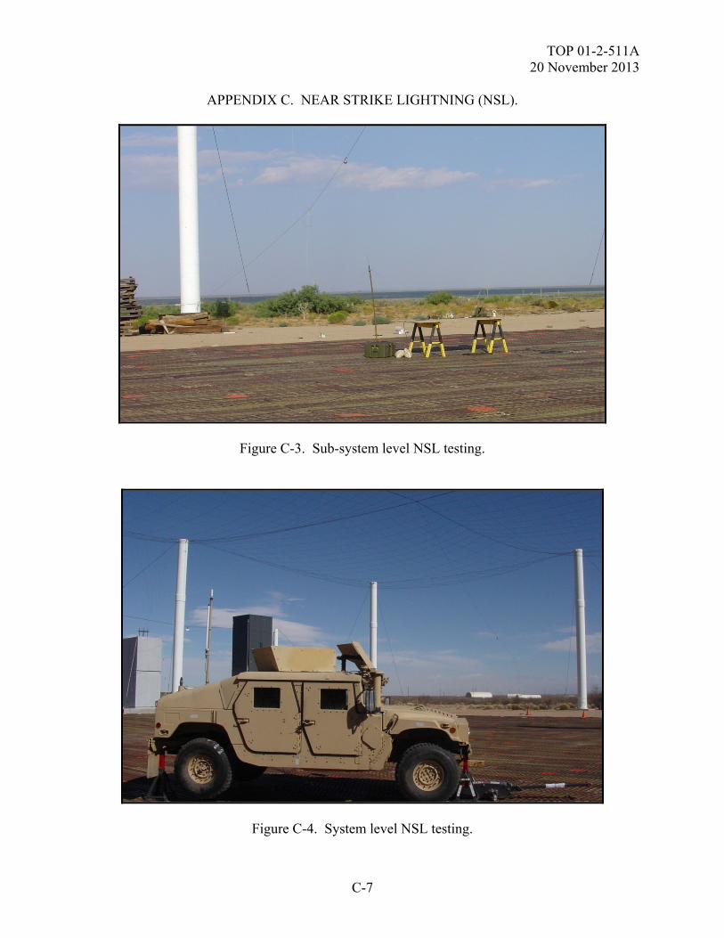
TOP 01-2-511A 20 November 2013
C-7
APPENDIX C. NEAR STRIKE LIGHTNING (NSL).
Figure C-3. Sub-system level NSL testing.
Figure C-4. System level NSL testing.
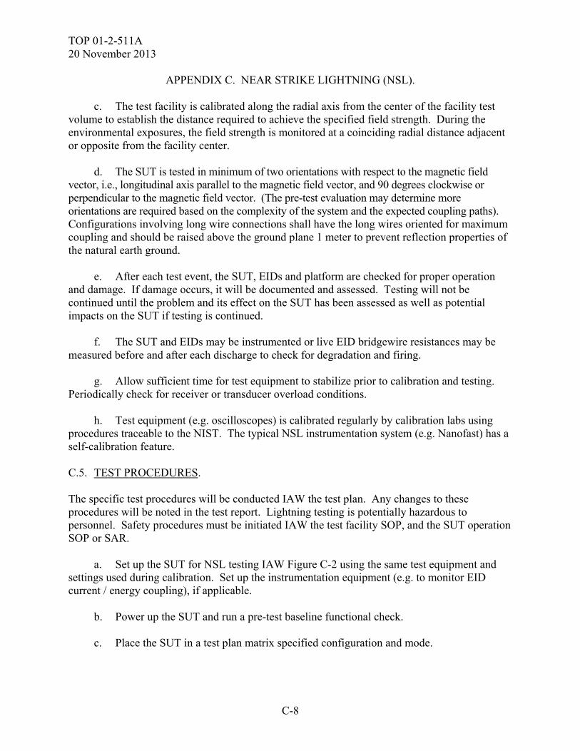
TOP 01-2-511A 20 November 2013
C-8
APPENDIX C. NEAR STRIKE LIGHTNING (NSL). c. The test facility is calibrated along the radial axis from the center of the facility test volume to establish the distance required to achieve the specified field strength. During the environmental exposures, the field strength is monitored at a coinciding radial distance adjacent or opposite from the facility center. d. The SUT is tested in minimum of two orientations with respect to the magnetic field vector, i.e., longitudinal axis parallel to the magnetic field vector, and 90 degrees clockwise or perpendicular to the magnetic field vector. (The pre-test evaluation may determine more orientations are required based on the complexity of the system and the expected coupling paths). Configurations involving long wire connections shall have the long wires oriented for maximum coupling and should be raised above the ground plane 1 meter to prevent reflection properties of the natural earth ground. e. After each test event, the SUT, EIDs and platform are checked for proper operation and damage. If damage occurs, it will be documented and assessed. Testing will not be continued until the problem and its effect on the SUT has been assessed as well as potential impacts on the SUT if testing is continued. f. The SUT and EIDs may be instrumented or live EID bridgewire resistances may be measured before and after each discharge to check for degradation and firing. g. Allow sufficient time for test equipment to stabilize prior to calibration and testing. Periodically check for receiver or transducer overload conditions. h. Test equipment (e.g. oscilloscopes) is calibrated regularly by calibration labs using procedures traceable to the NIST. The typical NSL instrumentation system (e.g. Nanofast) has a self-calibration feature. C.5. TEST PROCEDURES. The specific test procedures will be conducted IAW the test plan. Any changes to these procedures will be noted in the test report. Lightning testing is potentially hazardous to personnel. Safety procedures must be initiated IAW the test facility SOP, and the SUT operation SOP or SAR. a. Set up the SUT for NSL testing IAW Figure C-2 using the same test equipment and settings used during calibration. Set up the instrumentation equipment (e.g. to monitor EID current / energy coupling), if applicable. b. Power up the SUT and run a pre-test baseline functional check. c. Place the SUT in a test plan matrix specified configuration and mode.
TOP 01-2-511A 20 November 2013
C-9
APPENDIX C. NEAR STRIKE LIGHTNING (NSL). d. Verify data acquisition and instrumentation equipment operation. e. Secure the test area and insure that personnel are at a safe distance. f. The SUT is illuminated by the simulated NSL environment. If no failures occur, the SUT is illuminated at least three times per orientation or until data from all the data acquisition test points have been collected. g. After each discharge, perform a visual check of the SUT for any lightning induced damage. h. After each discharge, repeat SUT operational checks and compare to baseline. Throughout each NSL illumination, the SUT will be fully operational, in accordance with the SUT operating procedures. i. If there are any susceptibilities, determine the SUT components affected the required steps to recovery (e.g. cycling power) and the recovery time. If possible (if SUT not damaged), verify the repeatability of the susceptibility and determine the threshold and safety margins, if necessary. Should an upset occur, the effected equipment(s) and/or component(s) will be identified and the power cycled (OFF/ON) to re-establish normal operation and the time for recovery recorded. j. Repeat the test procedure for all test modes and configurations. Illuminate the SUT in different orientations (as defined during the pre-test analysis phase) at multiple levels (e.g. 50% and 100%) based upon the pre-test field calibration results. k. Any anomalies or upsets must be documented. Testing shall not continue until the problem is understood and its effects on the SUT are assessed. Should an upset occur, the affected equipment(s) and/or component(s) must be identified, and the power cycled (OFF/ON) in an attempt to re-establish normal operation. The time for recovery shall be recorded. Testing must be repeated at the same level and orientation to determine whether the upset is attributable to the specific EMP environment. l. Document the upsets, failures, downtime, and corrective actions. C.6. DATA PRESENTATION. Data presentation shall be as follows: a. SUT details (e.g. hardware and operational description, model and serial numbers), as well as applicable specific EID parameters
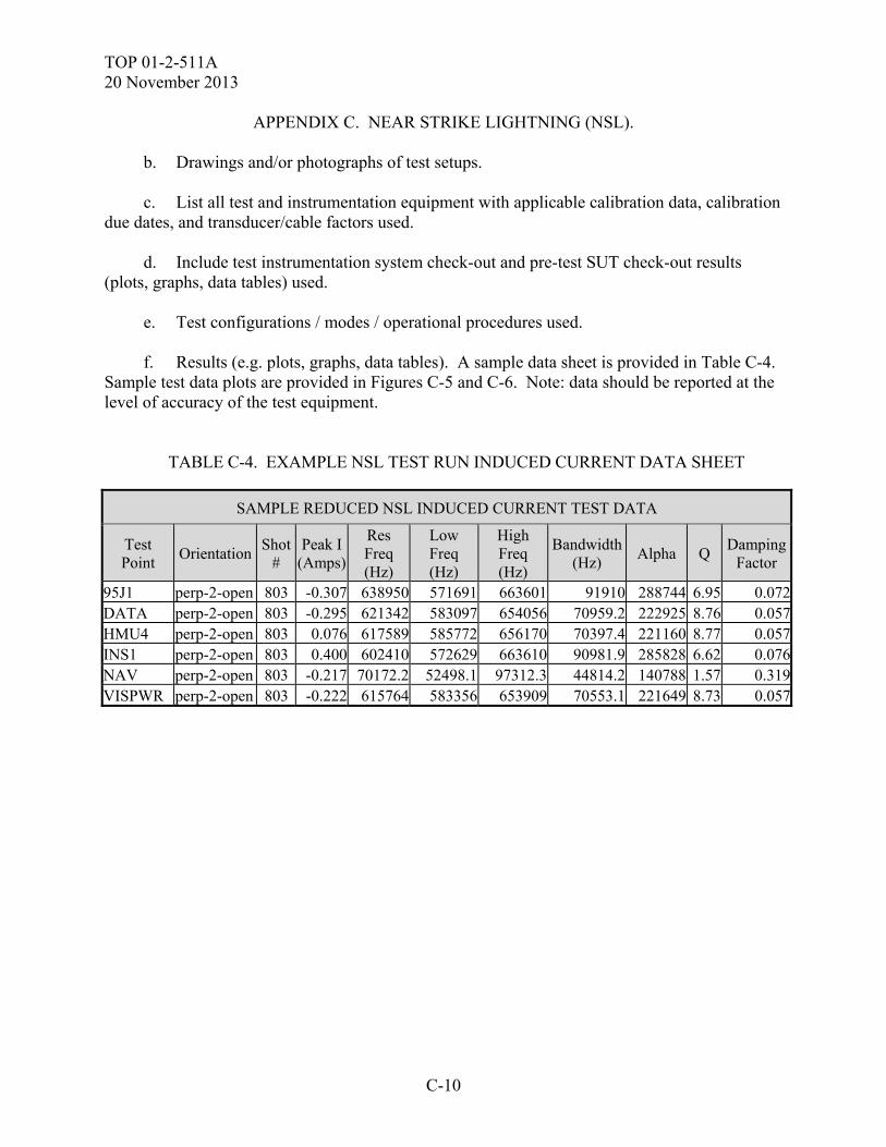
TOP 01-2-511A 20 November 2013
C-10
APPENDIX C. NEAR STRIKE LIGHTNING (NSL).
b. Drawings and/or photographs of test setups. c. List all test and instrumentation equipment with applicable calibration data, calibration due dates, and transducer/cable factors used. d. Include test instrumentation system check-out and pre-test SUT check-out results (plots, graphs, data tables) used. e. Test configurations / modes / operational procedures used. f. Results (e.g. plots, graphs, data tables). A sample data sheet is provided in Table C-4. Sample test data plots are provided in Figures C-5 and C-6. Note: data should be reported at the level of accuracy of the test equipment.
TABLE C-4. EXAMPLE NSL TEST RUN INDUCED CURRENT DATA SHEET
SAMPLE REDUCED NSL INDUCED CURRENT TEST DATA
Test Point
Orientation Shot
# Peak I
(Amps)
Res Freq (Hz)
Low Freq (Hz)
High Freq (Hz)
Bandwidth (Hz)
Alpha Q Damping
Factor
95J1 perp-2-open 803 -0.307 638950 571691 663601 91910 288744 6.95 0.072DATA perp-2-open 803 -0.295 621342 583097 654056 70959.2 222925 8.76 0.057HMU4 perp-2-open 803 0.076 617589 585772 656170 70397.4 221160 8.77 0.057INS1 perp-2-open 803 0.400 602410 572629 663610 90981.9 285828 6.62 0.076NAV perp-2-open 803 -0.217 70172.2 52498.1 97312.3 44814.2 140788 1.57 0.319VISPWR perp-2-open 803 -0.222 615764 583356 653909 70553.1 221649 8.73 0.057
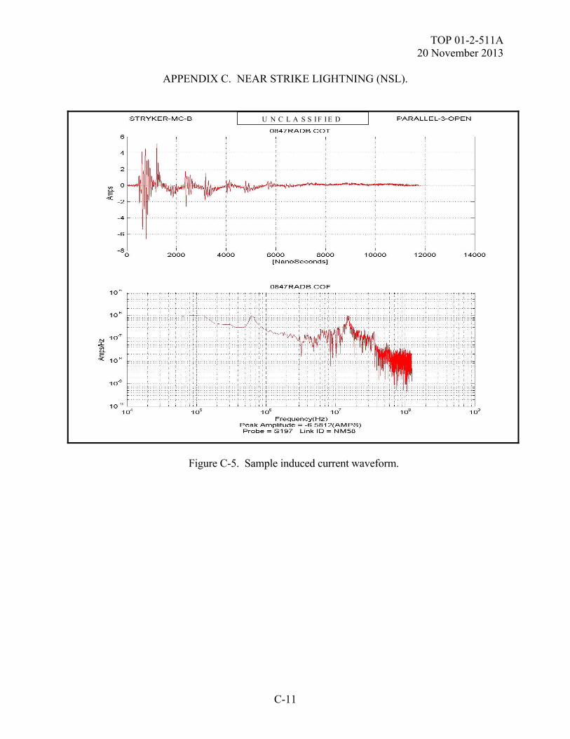
TOP 01-2-511A 20 November 2013
C-11
APPENDIX C. NEAR STRIKE LIGHTNING (NSL). U N C L A S S I F I E D
Figure C-5. Sample induced current waveform.
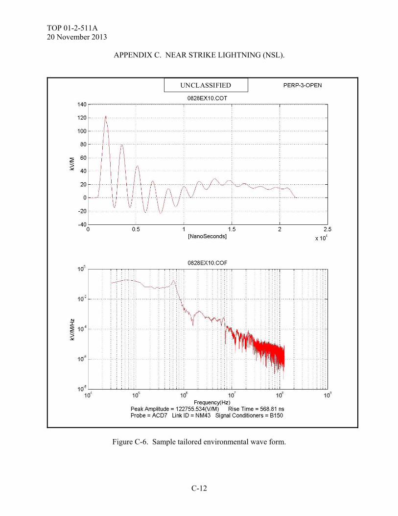
TOP 01-2-511A 20 November 2013
C-12
APPENDIX C. NEAR STRIKE LIGHTNING (NSL). UNCLASSIFIED
Figure C-6. Sample tailored environmental wave form.
TOP 01-2-511A 20 November 2013
C-13
APPENDIX C. NEAR STRIKE LIGHTNING (NSL). g. Present or reference limits or criteria used for comparison to test data. Include limits on plots and graphs. h. Changes to test plan and rationale. i. Discussion of results, conclusions and recommendations. (1) Description/discussion of anomalies and investigations. (2) Description of data reduction procedures / methods. C.7. DATA ANALYSIS. The test data will be compared to the applicable criteria and the pre-event baseline measurements to determine the extent to which the test criteria are met and the effects of the NSL test environment on the SUT. Facility criteria compliance should be addressed to ensure that any deficiencies are addressed either by increasing the amplitude of the environment, or application of direct drive techniques for compensation. Pre-existing analyses and test data from previous tests may also be used as a comparison for the new NSL test data. Test anomalies will be assessed to determine if they should be classified as SUT failures. Failures or degradation resulting in SUT performance outside specifications, will be addressed with regards to causes, test level at which they occurred, allowable downtime, and mission impact. Safety margins that could seriously impact mission performance or safety will be discussed. The test system configuration will be evaluated against the expected production configuration and the differences documented. Corrective hardening and/or mitigation recommendations will be developed and documented.

TOP 01-2-511A 20 November 2013
C-14
(This page is intentionally blank.)
TOP 01-2-511A 20 November 2013
D-1
APPENDIX D. ELECTROMAGNETIC PULSE (EMP). D.1. APPLICABILITY. a. This Appendix provides general test methods to assess the safety and survivability of the SUT to the effects produced by the EMP environment. This Appendix is meant to act as a guide and is not a replacement for a test plan. Compliance shall be verified by system-level test, analysis, or a combination thereof. b. This test method is applicable to equipment at the system level IAW the SUT specification. When the SUT is normally integrated into a platform, it is preferable to test it in that configuration but concerns about damage to the platform may drive the use of a test fixture that simulates the platform. The test fixture must be a suitable simulation that addresses the electrical properties of the platform (impedance, harnessing and coupling wavelength). D.2. REQUIREMENTS. a. The test parameters are extracted from MIL-STD-464, Electromagnetic Pulse (EMP). The system shall meet its operational performance requirements after being subjected to the EMP environment. This environment is classified and is currently defined in MIL-STD-2169B (Notice 1). EMP is a probability for most military systems and should be addressed on a case by case basis as any other electromagnetic environment. Guidance should not remove this requirement due to costs. It should be noted that in some instances, basic lightning preventative measures can mitigate EMP catastrophic failures. The Army Acquisition Executive (AAE) policy clearly states that all mission essential tactical systems shall conduct EMP testing. b. The SUT must perform its mission essential functions before and after exposure to a defined EMP event, as specified in the system requirement document, MIL-STD 464 or the Nuclear Survivability Criteria (NSC) developed by the United States Army Nuclear and Chemical Agency (USANCA). c. The system must operate and meet mission requirements after introduction of the EMP environment, or survive as specified in the system requirements document. d. There are also systems with the requirement to operate through the environment; i.e., missile defense programs must stay on line through the EMP event (function prior, during and post event). e. A system may also have an allowable recovery time in which the system must be brought back on line (through crew intervention).
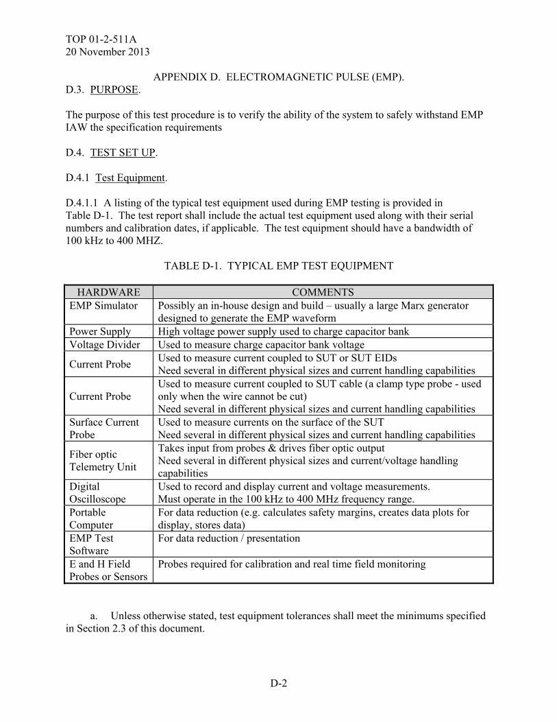
TOP 01-2-511A 20 November 2013
D-2
APPENDIX D. ELECTROMAGNETIC PULSE (EMP). D.3. PURPOSE. The purpose of this test procedure is to verify the ability of the system to safely withstand EMP IAW the specification requirements D.4. TEST SET UP. D.4.1 Test Equipment. D.4.1.1 A listing of the typical test equipment used during EMP testing is provided in Table D-1. The test report shall include the actual test equipment used along with their serial numbers and calibration dates, if applicable. The test equipment should have a bandwidth of 100 kHz to 400 MHZ.
TABLE D-1. TYPICAL EMP TEST EQUIPMENT
HARDWARE COMMENTS EMP Simulator Possibly an in-house design and build – usually a large Marx generator
designed to generate the EMP waveform Power Supply High voltage power supply used to charge capacitor bank Voltage Divider Used to measure charge capacitor bank voltage
Current Probe Used to measure current coupled to SUT or SUT EIDs Need several in different physical sizes and current handling capabilities
Current Probe Used to measure current coupled to SUT cable (a clamp type probe - used only when the wire cannot be cut) Need several in different physical sizes and current handling capabilities
Surface Current Probe
Used to measure currents on the surface of the SUT Need several in different physical sizes and current handling capabilities
Fiber optic Telemetry Unit
Takes input from probes & drives fiber optic output Need several in different physical sizes and current/voltage handling capabilities
Digital Oscilloscope
Used to record and display current and voltage measurements. Must operate in the 100 kHz to 400 MHz frequency range.
Portable Computer
For data reduction (e.g. calculates safety margins, creates data plots for display, stores data)
EMP Test Software
For data reduction / presentation
E and H Field Probes or Sensors
Probes required for calibration and real time field monitoring
a. Unless otherwise stated, test equipment tolerances shall meet the minimums specified in Section 2.3 of this document.
TOP 01-2-511A 20 November 2013
D-3
APPENDIX D. ELECTROMAGNETIC PULSE (EMP). b. Test equipment software used shall be documented as to dates, developer, version number, etc. D.4.1.2 SUT instrumentation is permissible but it shall not influence test results. Joint munitions must also follow the JOTP provided by the Joint Services Munitions Safety Test Working Group. SUT instrumentation may include the following: a. Current probes to measure the current coupled to one or more SUT wires / cables due to the EMP environment. b. Current probes to measure EID induced currents to determine EID safety margins where applicable. See HESD Appendix, page E-1. c. Voltage probes to measure ESAD firing capacitor induced voltages to determine ESAD safety margins. See HESD Appendix, page E-1. d. Cameras connected to monitors in a shielded instrumentation room using fiber optic lines. The cameras may be placed within shielded enclosures. e. Test sets may be used to check out the SUT before and after each test event or may be required to operate and monitor the SUT during testing. If required during testing, test sets should be protected from the test environment and placed as far away from the test volume as possible. Any test set interface cabling should be well shielded and aligned away from the strike point to minimize coupling. D.4.1.3 Pre-Test Evaluation. a. A pre-test evaluation will be performed to determine the primary current paths, ports of entry, test orientations and configurations, test conditions for the SUT, and bulk current measurement points. Energy coupling analysis will identify the type and capability requirements for the data acquisition system to include the bulk current probes. Usually, clamp-on inductive non-obtrusive current probes are used so as to not affect the inherent shielding integrity of the cable or the SUT shielding integrity. For hardening evaluation and corrective recommendations , the EMP test points should remain the same as Near Strike Lighting (NSL) test points or be a subset there of to include all signal, control and power cables. b. The SUT status is verified and documented before EMP testing, using baseline self-test checks, system operational performance checks, and functional performance measures.
D.4.1.4 Setup.
Some typical test setups and photographs are shown in Figures D-1 and D-2. Following are general / typical test setup guidelines.
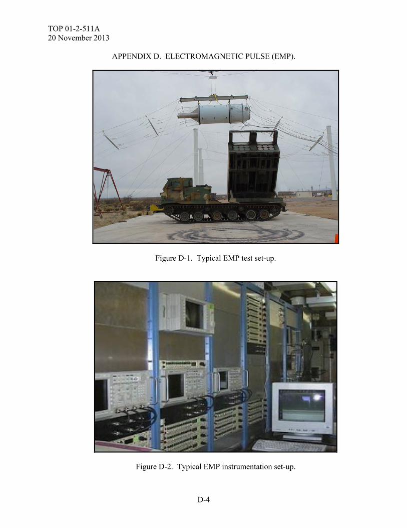
TOP 01-2-511A 20 November 2013
D-4
APPENDIX D. ELECTROMAGNETIC PULSE (EMP).
Figure D-1. Typical EMP test set-up.
Figure D-2. Typical EMP instrumentation set-up.
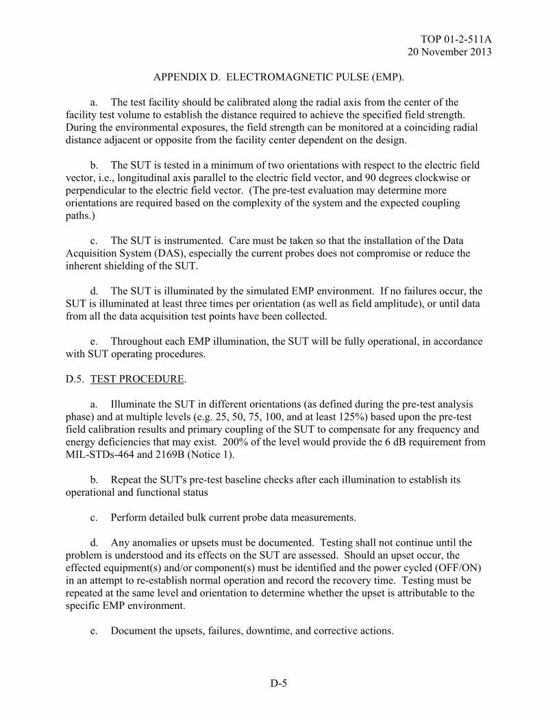
TOP 01-2-511A 20 November 2013
D-5
APPENDIX D. ELECTROMAGNETIC PULSE (EMP). a. The test facility should be calibrated along the radial axis from the center of the facility test volume to establish the distance required to achieve the specified field strength. During the environmental exposures, the field strength can be monitored at a coinciding radial distance adjacent or opposite from the facility center dependent on the design. b. The SUT is tested in a minimum of two orientations with respect to the electric field vector, i.e., longitudinal axis parallel to the electric field vector, and 90 degrees clockwise or perpendicular to the electric field vector. (The pre-test evaluation may determine more orientations are required based on the complexity of the system and the expected coupling paths.) c. The SUT is instrumented. Care must be taken so that the installation of the Data Acquisition System (DAS), especially the current probes does not compromise or reduce the inherent shielding of the SUT. d. The SUT is illuminated by the simulated EMP environment. If no failures occur, the SUT is illuminated at least three times per orientation (as well as field amplitude), or until data from all the data acquisition test points have been collected. e. Throughout each EMP illumination, the SUT will be fully operational, in accordance with SUT operating procedures. D.5. TEST PROCEDURE. a. Illuminate the SUT in different orientations (as defined during the pre-test analysis phase) and at multiple levels (e.g. 25, 50, 75, 100, and at least 125%) based upon the pre-test field calibration results and primary coupling of the SUT to compensate for any frequency and energy deficiencies that may exist. 200% of the level would provide the 6 dB requirement from MIL-STDs-464 and 2169B (Notice 1). b. Repeat the SUT's pre-test baseline checks after each illumination to establish its operational and functional status c. Perform detailed bulk current probe data measurements. d. Any anomalies or upsets must be documented. Testing shall not continue until the problem is understood and its effects on the SUT are assessed. Should an upset occur, the effected equipment(s) and/or component(s) must be identified and the power cycled (OFF/ON) in an attempt to re-establish normal operation and record the recovery time. Testing must be repeated at the same level and orientation to determine whether the upset is attributable to the specific EMP environment. e. Document the upsets, failures, downtime, and corrective actions.
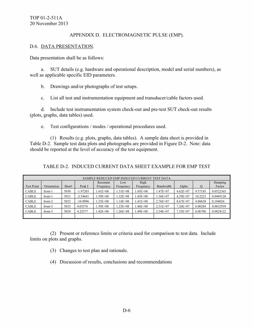
TOP 01-2-511A 20 November 2013
D-6
APPENDIX D. ELECTROMAGNETIC PULSE (EMP). D.6. DATA PRESENTATION. Data presentation shall be as follows: a. SUT details (e.g. hardware and operational description, model and serial numbers), as well as applicable specific EID parameters. b. Drawings and/or photographs of test setups. c. List all test and instrumentation equipment and transducer/cable factors used. d. Include test instrumentation system check-out and pre-test SUT check-out results (plots, graphs, data tables) used. e. Test configurations / modes / operational procedures used. (1) Results (e.g. plots, graphs, data tables). A sample data sheet is provided in Table D-2. Sample test data plots and photographs are provided in Figure D-2. Note: data should be reported at the level of accuracy of the test equipment.
TABLE D-2. INDUCED CURRENT DATA SHEET EXAMPLE FOR EMP TEST
SAMPLE REDUCED EMP INDUCED CURRENT TEST DATA
Test Point Orientation Shot# Peak I Resonant Frequency
Low Frequency
High Frequency Bandwidth Alpha Q
Damping Factor
CABLE front-1 5030 -1.97203 1.41E+08 1.31E+08 1.45E+08 1.47E+07 4.62E+07 9.57185 0.0522365
CABLE front-1 5031 -2.54641 1.39E+08 1.32E+08 1.45E+08 1.36E+07 4.29E+07 10.2223 0.0489128
CABLE front-2 5032 -10.9096 1.33E+08 1.14E+08 1.41E+08 2.76E+07 8.67E+07 4.80658 0.104024
CABLE front-3 5033 4.03576 1.39E+08 1.23E+08 1.46E+08 2.31E+07 7.26E+07 6.00284 0.0832939
CABLE front-3 5034 4.22577 1.42E+08 1.26E+08 1.49E+08 2.34E+07 7.35E+07 6.06706 0.0824122
(2) Present or reference limits or criteria used for comparison to test data. Include limits on plots and graphs. (3) Changes to test plan and rationale. (4) Discussion of results, conclusions and recommendations
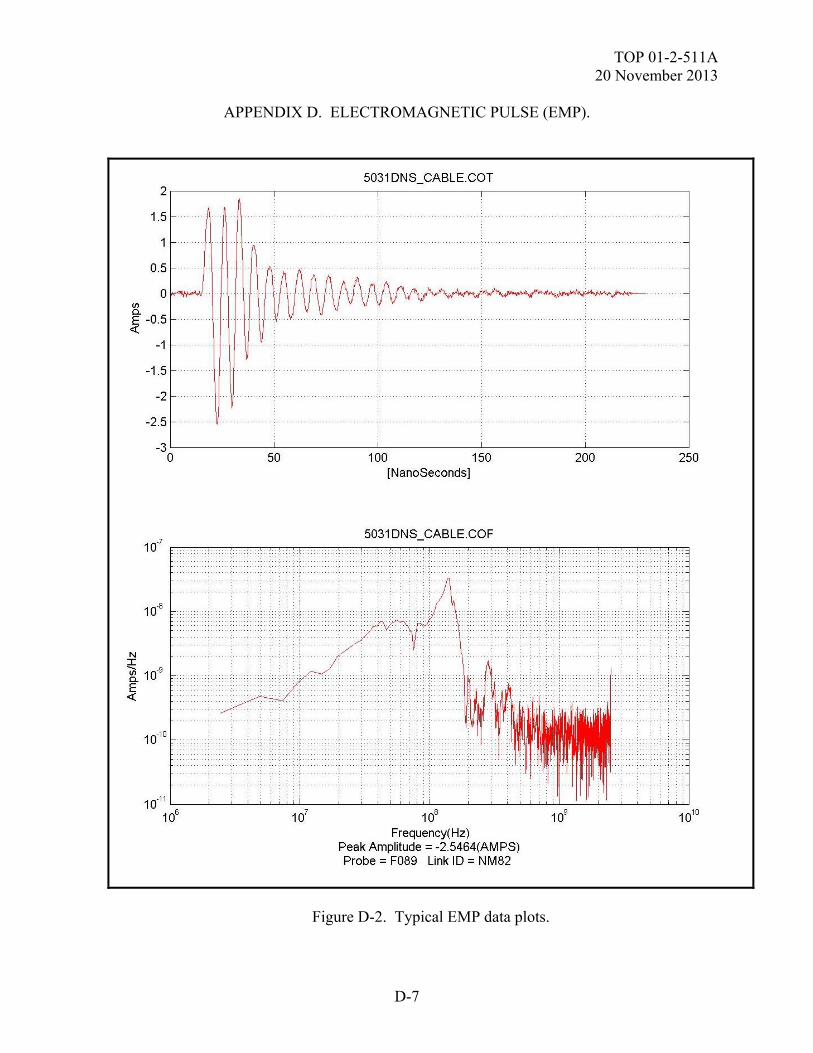
TOP 01-2-511A 20 November 2013
D-7
APPENDIX D. ELECTROMAGNETIC PULSE (EMP).
Figure D-2. Typical EMP data plots.
TOP 01-2-511A 20 November 2013
D-8
APPENDIX D. ELECTROMAGNETIC PULSE (EMP). D.7. DATA ANALYSIS PROCEDURE. The test data will be compared to the applicable criteria and the pre-event baseline measurements to determine the extent to which the test criteria are met and the effects of the EMP test environment on the SUT. Facility criteria compliance should be addressed to ensure that any deficiencies are addressed either by increasing the amplitude of the environment, or application of direct drive techniques for compensation. Pre-existing analyses and test data from previous tests may also be used as a comparison for the new EMP test data. Test anomalies will be assessed to determine if they should be classified as SUT failures. Failures or degradation resulting in SUT performance outside specifications, will be addressed with regards to causes, test level at which they occurred, allowable downtime, and mission impact. Safety margins that could seriously impact mission performance or safety will be discussed. The test system configuration will be evaluated against the expected production configuration and the differences documented. Corrective hardening and/or mitigation recommendations will be developed and documented.
TOP 01-2-511A 20 November 2013
E-1
APPENDIX E. HELICOPTER GENERATED ELECTROSTATIC DISCHARGE (HESD). E.1. APPLICABILITY. a. This Appendix provides general test methods to assess the safety and survivability of the SUT to the effects produced by the Helicopter-generated Electrostatic Discharge (HESD) environment. This Appendix is meant to act as a guide and is not a replacement for a test plan. Compliance shall be verified by system-level test, analysis, or a combination thereof. b. The HESD or “vertical lift” environment was developed from measuring the charge build-up on helicopters, and is applicable to any equipment that may be transported by helicopter including equipment loaded onto and unloaded from a helicopter or carried by the helicopter using a sling, as well as equipment carried on personnel. It is also applicable to equipment installed external to the helicopter such as ordnance and fuel tanks. The applicability of the HESD environment has been extended by ADS-37A-PRF to all Army aircraft. c. HESD testing is applicable at the system level IAW SUT specification. When the SUT is normally integrated into a platform, it is preferable to test it in that configuration but concerns about damage to the platform may drive the use of a test fixture that simulates the platform. HESD testing may apply in multiple configurations such as shipping because the SUT may be transported by helicopter. HESD testing is usually applicable to the SUT un-powered but may be applied when powered if the SUT is flight critical equipment, or equipment carried by Special Operation Forces personnel. The HESD environment is applied at points on the SUT that are contact points during loading and unloading including sling attachment points, and the bottom corners of the SUT which would make first contact when being loaded or unloaded. Note that if the SUT is integrated into a ground vehicle which is transported by aircraft, the contact points would be the points on the ground vehicle which make first contact during loading or unloading and its sling loading points. E.2. REQUIREMENTS. a. When exposed to the HESD environment, the SUT (and its platform, if any) shall meet the operational performance requirements detailed in their equipment specifications and test plan. A typical SUT HESD requirement is shown below. When the SUT is not flight or safety critical, often the “during and” is removed from the performance part of the requirement. Note that ADS-37A-PRF extends the requirement to all Army aircraft, not just helicopters. b. The SUT shall remain safe in its helicopter transport configuration during and after exposure to the HESD environment and shall meet its operational performance requirements during and after exposure to the HESD environment. The HESD environment shall be as specified in MIL-STD-464. c. The simulated HESD environment is defined in MIL-STD-464. The HESD test pulse parameters for Vertical Lift and In-Flight Refueling detailed in Table E-1 standardize the HESD pulse and simulate the equivalent circuit of the aircraft from which the electrostatic discharge may take place.
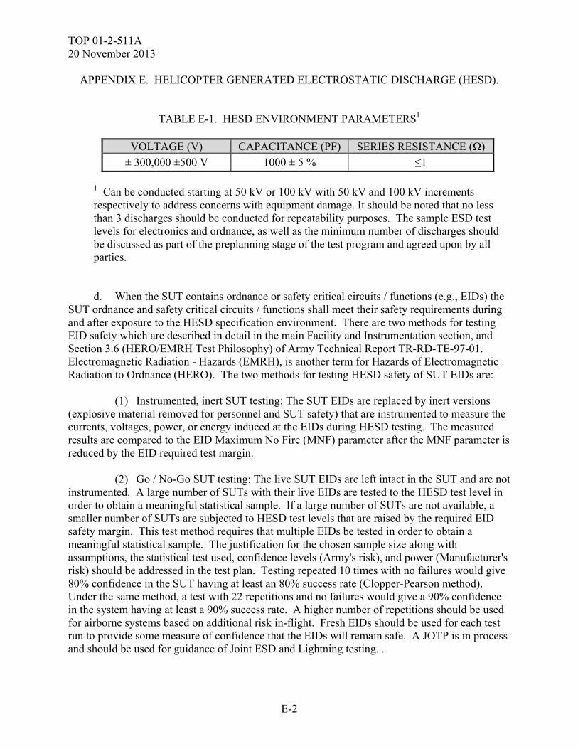
TOP 01-2-511A 20 November 2013
E-2
APPENDIX E. HELICOPTER GENERATED ELECTROSTATIC DISCHARGE (HESD).
TABLE E-1. HESD ENVIRONMENT PARAMETERS1
VOLTAGE (V) CAPACITANCE (PF) SERIES RESISTANCE (Ω)
± 300,000 ±500 V 1000 ± 5 % ≤1
1 Can be conducted starting at 50 kV or 100 kV with 50 kV and 100 kV increments respectively to address concerns with equipment damage. It should be noted that no less than 3 discharges should be conducted for repeatability purposes. The sample ESD test levels for electronics and ordnance, as well as the minimum number of discharges should be discussed as part of the preplanning stage of the test program and agreed upon by all parties.
d. When the SUT contains ordnance or safety critical circuits / functions (e.g., EIDs) the SUT ordnance and safety critical circuits / functions shall meet their safety requirements during and after exposure to the HESD specification environment. There are two methods for testing EID safety which are described in detail in the main Facility and Instrumentation section, and Section 3.6 (HERO/EMRH Test Philosophy) of Army Technical Report TR-RD-TE-97-01. Electromagnetic Radiation - Hazards (EMRH), is another term for Hazards of Electromagnetic Radiation to Ordnance (HERO). The two methods for testing HESD safety of SUT EIDs are: (1) Instrumented, inert SUT testing: The SUT EIDs are replaced by inert versions (explosive material removed for personnel and SUT safety) that are instrumented to measure the currents, voltages, power, or energy induced at the EIDs during HESD testing. The measured results are compared to the EID Maximum No Fire (MNF) parameter after the MNF parameter is reduced by the EID required test margin. (2) Go / No-Go SUT testing: The live SUT EIDs are left intact in the SUT and are not instrumented. A large number of SUTs with their live EIDs are tested to the HESD test level in order to obtain a meaningful statistical sample. If a large number of SUTs are not available, a smaller number of SUTs are subjected to HESD test levels that are raised by the required EID safety margin. This test method requires that multiple EIDs be tested in order to obtain a meaningful statistical sample. The justification for the chosen sample size along with assumptions, the statistical test used, confidence levels (Army's risk), and power (Manufacturer's risk) should be addressed in the test plan. Testing repeated 10 times with no failures would give 80% confidence in the SUT having at least an 80% success rate (Clopper-Pearson method). Under the same method, a test with 22 repetitions and no failures would give a 90% confidence in the system having at least a 90% success rate. A higher number of repetitions should be used for airborne systems based on additional risk in-flight. Fresh EIDs should be used for each test run to provide some measure of confidence that the EIDs will remain safe. A JOTP is in process and should be used for guidance of Joint ESD and Lightning testing. .
TOP 01-2-511A 20 November 2013
E-3
APPENDIX E. HELICOPTER GENERATED ELECTROSTATIC DISCHARGE (HESD). e. Go/No-Go SUT testing can be performed but may have several concerns: (1) The need for a large number of SUTs to test to a wide variety of test field conditions (e.g. different frequencies, waveforms, polarizations, orientations). A large number of SUTs may not be available. (2) The chance of destruction of a large number of SUTs. (3) High test levels required may not be obtainable. (4) Fully testing a large number of SUTs considerably increases test cost and schedule. (5) Test personnel and test equipment safety. f. Each test location is tested with both positive and negative polarity ESD transients. E.3. PURPOSE. The purpose of HESD testing is to verify the ability of the SUT to withstand the HESD environment IAW its specification performance requirements detailed in the test plan. A typical test plan purpose follows: The purpose of HESD testing is to determine if the SUT remains safe (e.g. no ordnance ignition) during and after being subjected to the HESD environment when in a storage or transportation configuration and that the SUT meets its operational performance requirements (e.g. no damage or degraded performance) after being subjected to the HESD environment when tested un-powered in an operational configuration. E.4. TEST SET UP. E.4.1 Test Equipment. A listing of the typical test equipment used during HESD testing is provided in Table E-2. The test report shall include the actual test equipment used along with their serial numbers and calibration dates, if applicable. a. The test generation equipment consists of a capacitor bank to simulate the HESD waveform, a power supply to charge it up and a switching network to discharge it. b. The test measurement equipment consists of an oscilloscope and current probe to measure the stimulus current waveforms to determine the adequacy of the simulated HESD environment and a voltage divider network to measure the HESD simulator capacitor bank voltage. The test measurement equipment is required to operate in the HESD environment frequency range (100 kHz to 100 MHz) as a minimum.
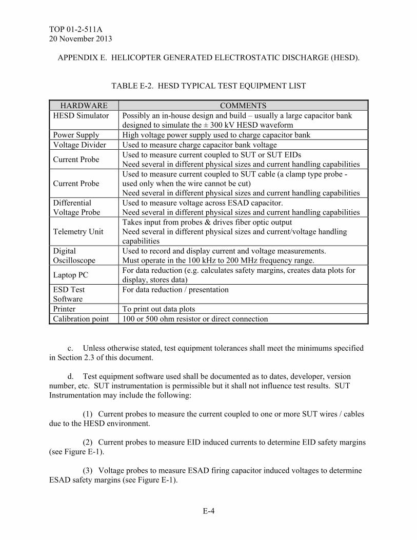
TOP 01-2-511A 20 November 2013
E-4
APPENDIX E. HELICOPTER GENERATED ELECTROSTATIC DISCHARGE (HESD).
TABLE E-2. HESD TYPICAL TEST EQUIPMENT LIST
HARDWARE COMMENTS HESD Simulator Possibly an in-house design and build – usually a large capacitor bank
designed to simulate the ± 300 kV HESD waveform Power Supply High voltage power supply used to charge capacitor bank Voltage Divider Used to measure charge capacitor bank voltage
Current Probe Used to measure current coupled to SUT or SUT EIDs Need several in different physical sizes and current handling capabilities
Current Probe Used to measure current coupled to SUT cable (a clamp type probe - used only when the wire cannot be cut) Need several in different physical sizes and current handling capabilities
Differential Voltage Probe
Used to measure voltage across ESAD capacitor. Need several in different physical sizes and current handling capabilities
Telemetry Unit Takes input from probes & drives fiber optic output Need several in different physical sizes and current/voltage handling capabilities
Digital Oscilloscope
Used to record and display current and voltage measurements. Must operate in the 100 kHz to 200 MHz frequency range.
Laptop PC For data reduction (e.g. calculates safety margins, creates data plots for display, stores data)
ESD Test Software
For data reduction / presentation
Printer To print out data plots Calibration point 100 or 500 ohm resistor or direct connection
c. Unless otherwise stated, test equipment tolerances shall meet the minimums specified in Section 2.3 of this document. d. Test equipment software used shall be documented as to dates, developer, version number, etc. SUT instrumentation is permissible but it shall not influence test results. SUT Instrumentation may include the following: (1) Current probes to measure the current coupled to one or more SUT wires / cables due to the HESD environment. (2) Current probes to measure EID induced currents to determine EID safety margins (see Figure E-1). (3) Voltage probes to measure ESAD firing capacitor induced voltages to determine ESAD safety margins (see Figure E-1).
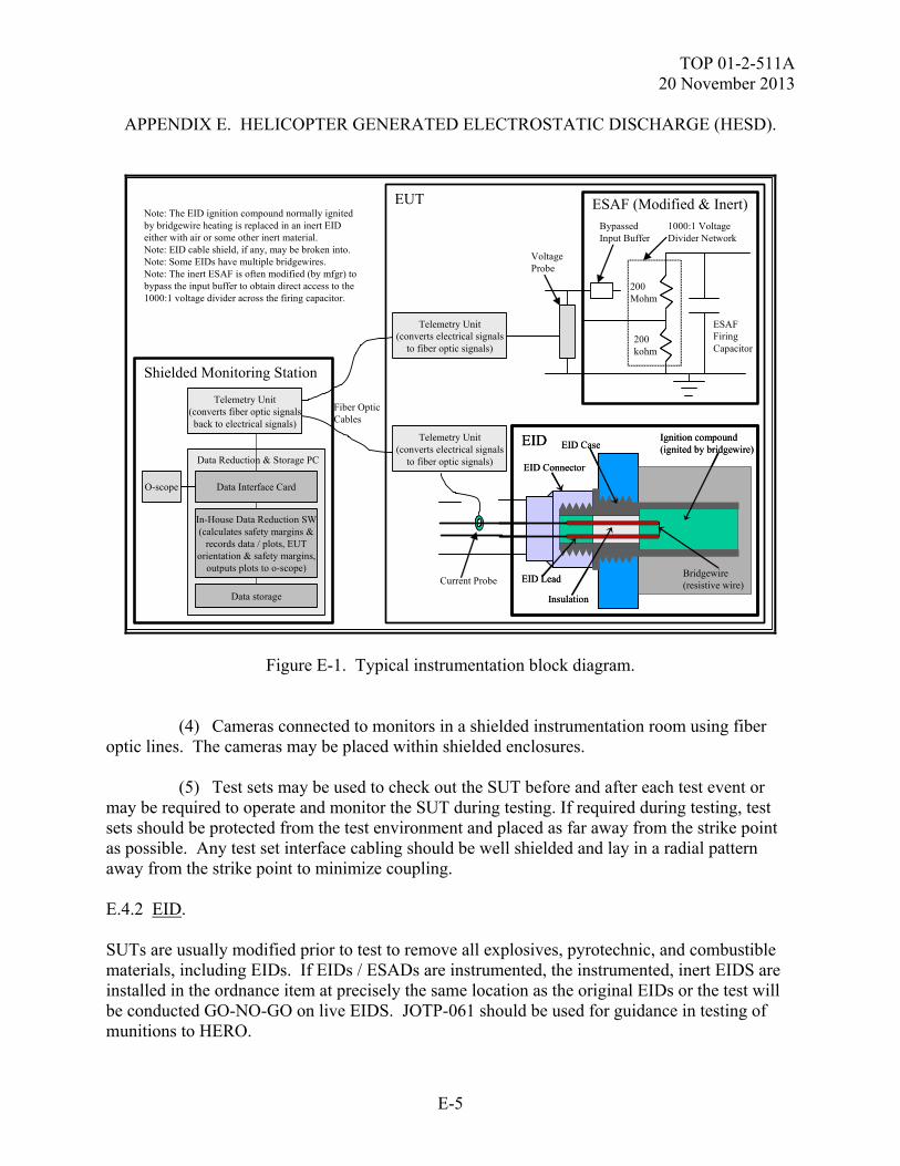
TOP 01-2-511A 20 November 2013
E-5
APPENDIX E. HELICOPTER GENERATED ELECTROSTATIC DISCHARGE (HESD).
Shielded Monitoring Station
Fiber OpticCables
Data Reduction & Storage PC
Data Interface Card
In-House Data Reduction SW(calculates safety margins &
records data / plots, EUTorientation & safety margins,
outputs plots to o-scope)
Data storage
Note: The EID ignition compound normally ignitedby bridgewire heating is replaced in an inert EIDeither with air or some other inert material.Note: EID cable shield, if any, may be broken into.Note: Some EIDs have multiple bridgewires.Note: The inert ESAF is often modified (by mfgr) tobypass the input buffer to obtain direct access to the1000:1 voltage divider across the firing capacitor.
EID
Bridgewire(resistive wire)
EID Connector
Insulation
EID Lead
EID CaseIgnition compound(ignited by bridgewire)
EID
Bridgewire(resistive wire)
EID Connector
Insulation
EID Lead
EID CaseIgnition compound(ignited by bridgewire)
ESAF (Modified & Inert)
ESAFFiringCapacitor
BypassedInput Buffer
200Mohm
200kohm
1000:1 VoltageDivider Network
Current Probe
VoltageProbe
Telemetry Unit(converts electrical signals
to fiber optic signals)
Telemetry Unit(converts electrical signals
to fiber optic signals)
EUT
O-scope
Telemetry Unit(converts fiber optic signalsback to electrical signals)
Figure E-1. Typical instrumentation block diagram. (4) Cameras connected to monitors in a shielded instrumentation room using fiber optic lines. The cameras may be placed within shielded enclosures. (5) Test sets may be used to check out the SUT before and after each test event or may be required to operate and monitor the SUT during testing. If required during testing, test sets should be protected from the test environment and placed as far away from the strike point as possible. Any test set interface cabling should be well shielded and lay in a radial pattern away from the strike point to minimize coupling. E.4.2 EID. SUTs are usually modified prior to test to remove all explosives, pyrotechnic, and combustible materials, including EIDs. If EIDs / ESADs are instrumented, the instrumented, inert EIDS are installed in the ordnance item at precisely the same location as the original EIDs or the test will be conducted GO-NO-GO on live EIDS. JOTP-061 should be used for guidance in testing of munitions to HERO.
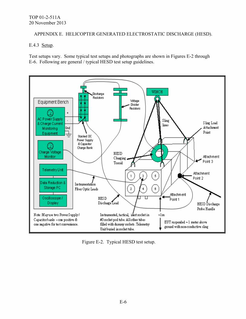
TOP 01-2-511A 20 November 2013
E-6
APPENDIX E. HELICOPTER GENERATED ELECTROSTATIC DISCHARGE (HESD). E.4.3 Setup. Test setups vary. Some typical test setups and photographs are shown in Figures E-2 through E-6. Following are general / typical HESD test setup guidelines.
Figure E-2. Typical HESD test setup.
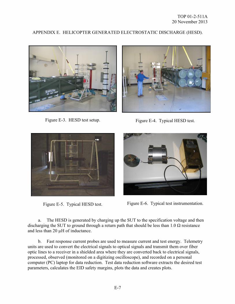
TOP 01-2-511A 20 November 2013
E-7
APPENDIX E. HELICOPTER GENERATED ELECTROSTATIC DISCHARGE (HESD).
Figure E-3. HESD test setup.
Figure E-4. Typical HESD test.
Figure E-5. Typical HESD test.
Figure E-6. Typical test instrumentation. a. The HESD is generated by charging up the SUT to the specification voltage and then discharging the SUT to ground through a return path that should be less than 1.0 Ω resistance and less than 20 µH of inductance. b. Fast response current probes are used to measure current and test energy. Telemetry units are used to convert the electrical signals to optical signals and transmit them over fiber optic lines to a receiver in a shielded area where they are converted back to electrical signals, processed, observed (monitored on a digitizing oscilloscope), and recorded on a personal computer (PC) laptop for data reduction. Test data reduction software extracts the desired test parameters, calculates the EID safety margins, plots the data and creates plots.
TOP 01-2-511A 20 November 2013
E-8
APPENDIX E. HELICOPTER GENERATED ELECTROSTATIC DISCHARGE (HESD). c. Due to concerns with damaging the platform (e.g. aircraft), when an SUT is integrated into a platform, a test platform (e.g. aircraft shell) may be used. When it is not platform mounted, the SUT is usually mounted on a non-conductive test fixture isolated from the ground or is sling loaded up off the ground. When it is platform mounted, it is mounted on the platform (or test shell) and the platform is isolated from the ground (e.g. a sling loaded HMMWV). To avoid un-intentional discharge, the SUT or platform is raised a minimum of one meter above the ground and away from conductive materials or structures. All SUT cabling is terminated. Dummy loads are typically used on un-connected SUT interface cables to increase simulation fidelity. The SUT may be tested in several different configurations (e.g., storage, transport, operational). The SUT is typically un-powered during HESD testing but flight critical equipment may be tested when powered and operational. d. Discharge point selection is typically based on the points that may be contacted during helicopter loading, unloading and sling transport. These may include sling contact points and the points that would most likely touch the helicopter, ground or personnel first during sling transport or aircraft loading / unloading. Aircraft externally mounted equipment is usually tested at critical safety points (e.g., missile warhead), ends, and manhandling (loading / loading / maintenance) points. Each test location is tested with both positive and negative polarity ESD transients. If the possibility of SUT damage is envisioned, testing may be stepped up (e.g., performed at ±50 kV, 100 kV, 150 kV, and ±200 kV first). Each test location is documented and photographed for test report clarity. e. After each test discharge, the SUT, EIDs & platform are checked for proper operation. Testing will not be continued until the problem and its effect on the SUT has been assessed as well as potential impacts on the SUT if testing is continued. f. The SUT and EIDs may be instrumented. EID bridgewire resistances (live or inert) may be measured before and after each discharge to check for degradation and firing. g. The typical HESD instrumentation system (e.g. Nanofast) has a self-calibration feature. E.5. TEST PROCEDURES. The specific test procedures will be conducted IAW the test plan. The exact order of testing may be altered for test efficiency with the approval of the test manager. Any changes to these procedures will be noted in the test report. HESD testing is potentially hazardous to personnel. Safety procedures must be initiated IAW the test facility SOPs, and the SUT operation SOP and SAR. E.5.1 Calibration (to verify simulator produces specification waveform): This should be conducted on the day of testing to preserve the configuration integrity.
TOP 01-2-511A 20 November 2013
E-9
APPENDIX E. HELICOPTER GENERATED ELECTROSTATIC DISCHARGE (HESD). a. Set up the HESD generator with settings that past experience has shown to discharge per the specification waveform parameters. Set up the voltage divider network to monitor the capacitor bank charge voltage. Place the high voltage toroid on a conductive surface to ground as a test setup checkout. b. Secure the test area and insure that personnel are at a safe distance. c. Charge up the HESD generator to the positive specification level. Note: if the possibility of SUT damage is envisioned, calibration and testing may be stepped up (e.g. performed at + 50 kV, 100 kV, 150 kV, and + 200 kV first). d. Discharge the HESD generator by contacting the handheld ground return rod directly to the toroid. Repeat, adjusting the HESD generator until the HESD criteria is obtained. e. Record the HESD generator calibration settings. f. Repeat calibration for the negative specification levels. g. Verify that the HESD generator is in a safe configuration. E.5.2 ESAD Test. a. Set up the SUT for HESD testing using the same test equipment and settings used during calibration. Set up the voltage divider network to monitor the capacitor bank charge voltage. Set up the instrumentation equipment (e.g. to monitor EID current / energy coupling), if applicable. Electrically isolate the SUT. Place the HESD toroid in contact with the SUT. b. Connect the instrumentation to the data processing/collection system (oscilloscope and PC) using the telemetry system and fiber optic cables. c. Place the SUT in a test plan matrix specified configuration and mode. d. Verify data acquisition and instrumentation equipment operation. Exercise self-calibration features, if any. Test EIDs and their associated firing circuit continuity and operation. e. Power up the SUT and run pre-test baseline functional checks. f. Secure the test area and insure that personnel are at a safe distance.
TOP 01-2-511A 20 November 2013
E-10
APPENDIX E. HELICOPTER GENERATED ELECTROSTATIC DISCHARGE (HESD). g. Charge the HESD generator to the positive specification level using the settings determined during calibration. Then remove the generator from the circuit. Because the SUT is isolated, the charge will distribute itself from the toroid over the SUT structure simulating HESD charging effects. Note: if the possibility of SUT damage is envisioned, testing may be stepped up (e.g., performed at +100 kV and +200 kV first). h. Discharge the charge on the SUT by moving the HESD ground contact probe toward an SUT test point until discharge occurs. i. Verify the HESD generator is in a safe configuration. j. After each discharge, examine the data to ensure that the HESD criteria were simulated, the test data is adequate, and the data is within pass/fail criteria. Calculate safety margins and measure EID bridgewire resistance (live or inert), if required. k. After each discharge, perform a visual check for any HESD induced damage. l. After each discharge, repeat SUT operational checks and compare to baseline. m. If there are susceptibilities, determine the SUT components affected the required steps to recovery (e.g. cycling power) and the recovery time. If possible (if SUT not damaged), verify the repeatability of the susceptibility and determine the threshold and safety margins, if necessary. n. Record the following for each discharge and mark on plots: (1) Stimulus waveform parameter data / plots. (2) Test configuration / test mode (3) Test discharge point. (4) Post-discharge functional check pass/fail results. (5) Visual damage inspection results. (6) SUT responses (e.g., components affected, wire/cable currents, EID currents, SUT upsets, recovery times, etc.). (7) EIDs monitored; their calculated SMs and whether they met requirements. (8) EID bridgewire resistance and determination of degradation, if required. (9) Date, time, location.
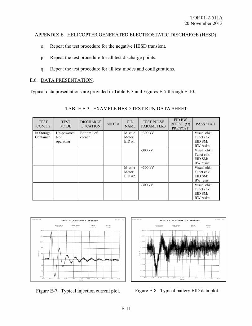
TOP 01-2-511A 20 November 2013
E-11
APPENDIX E. HELICOPTER GENERATED ELECTROSTATIC DISCHARGE (HESD). o. Repeat the test procedure for the negative HESD transient. p. Repeat the test procedure for all test discharge points. q. Repeat the test procedure for all test modes and configurations. E.6. DATA PRESENTATION. Typical data presentations are provided in Table E-3 and Figures E-7 through E-10.
TABLE E-3. EXAMPLE HESD TEST RUN DATA SHEET
TEST CONFIG
TEST MODE
DISCHARGE LOCATION
SHOT # EID
NAME TEST PULSE
PARAMETERS
EID BW RESIST. (Ω) PRE/POST
PASS / FAIL
In Storage Container
Un-powered Not operating
Bottom Left corner
Missile Motor EID #1
+300 kV Visual chk: Funct chk: EID SM: BW resist:
-300 kV Visual chk: Funct chk: EID SM: BW resist:
Missile Motor EID #2
+300 kV Visual chk: Funct chk: EID SM: BW resist:
-300 kV Visual chk: Funct chk: EID SM: BW resist:
Figure E-7. Typical injection current plot.
Figure E-8. Typical battery EID data plot.
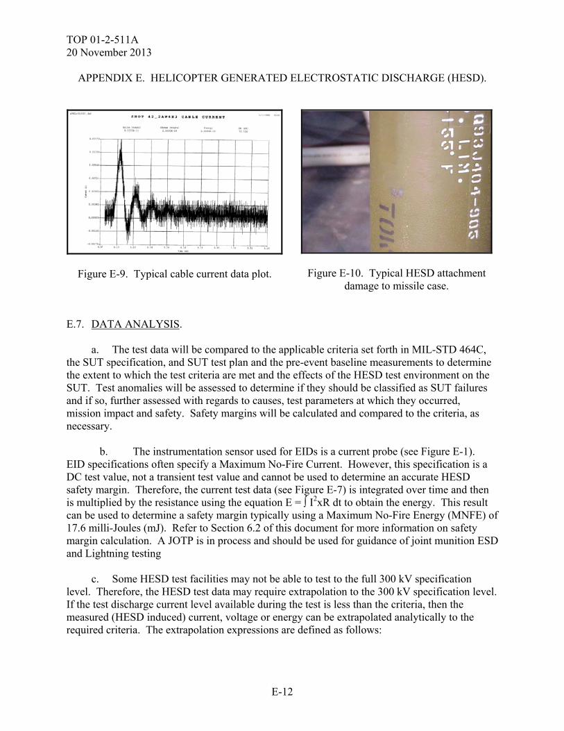
TOP 01-2-511A 20 November 2013
E-12
APPENDIX E. HELICOPTER GENERATED ELECTROSTATIC DISCHARGE (HESD).
Figure E-9. Typical cable current data plot.
Figure E-10. Typical HESD attachment damage to missile case.
E.7. DATA ANALYSIS. a. The test data will be compared to the applicable criteria set forth in MIL-STD 464C, the SUT specification, and SUT test plan and the pre-event baseline measurements to determine the extent to which the test criteria are met and the effects of the HESD test environment on the SUT. Test anomalies will be assessed to determine if they should be classified as SUT failures and if so, further assessed with regards to causes, test parameters at which they occurred, mission impact and safety. Safety margins will be calculated and compared to the criteria, as necessary. b. The instrumentation sensor used for EIDs is a current probe (see Figure E-1). EID specifications often specify a Maximum No-Fire Current. However, this specification is a DC test value, not a transient test value and cannot be used to determine an accurate HESD safety margin. Therefore, the current test data (see Figure E-7) is integrated over time and then is multiplied by the resistance using the equation E = ∫ I2xR dt to obtain the energy. This result can be used to determine a safety margin typically using a Maximum No-Fire Energy (MNFE) of 17.6 milli-Joules (mJ). Refer to Section 6.2 of this document for more information on safety margin calculation. A JOTP is in process and should be used for guidance of joint munition ESD and Lightning testing c. Some HESD test facilities may not be able to test to the full 300 kV specification level. Therefore, the HESD test data may require extrapolation to the 300 kV specification level. If the test discharge current level available during the test is less than the criteria, then the measured (HESD induced) current, voltage or energy can be extrapolated analytically to the required criteria. The extrapolation expressions are defined as follows:

TOP 01-2-511A 20 November 2013
E-13
APPENDIX E. HELICOPTER GENERATED ELECTROSTATIC DISCHARGE (HESD). ENERGY: Eextrapolated = Einduced (Icriteria / Itest)
2 Where Eextrapolated = the extrapolated value of the induced energy (J) The extrapolated value for energy can then used in place of the measured induced energy value to calculate the safety margin or the following expression can be used:
SMextrapolated (dB) = 10 log10 (EMNF / Einduced) × K Where K = (Icriteria / Itest)
2 CURRENT: Iextrapolated = Iinduced (Icriteria / Itest) Where Iextrapolated = the extrapolated value of the induced current (A) Icriteria = the required (criteria) discharge current (A) Itest = the actual discharge current amplitude measured during test (A) The extrapolated value for current can then used in place of the measured induced current value to calculate the safety margin or the following expression can be used:
SMextrapolated (dB) = 20 log10 (IMNF / Iinduced) × K Where K = (Icriteria / Itest) < 1 VOLTAGE: Vextrapolated = Vinduced (Icriteria / Itest) Where Vextrapolated = the extrapolated value of the induced voltage (V) The extrapolated value for voltage can then used in place of the measured induced voltage value to calculate the safety margin or the following expression can be used:
SMextrapolated (dB) = 20 log10 (MFV / Vinduced) × K Where K = (Icriteria / Itest) < 1

TOP 01-2-511A 20 November 2013
E-14
(This page is intentionally blank.)
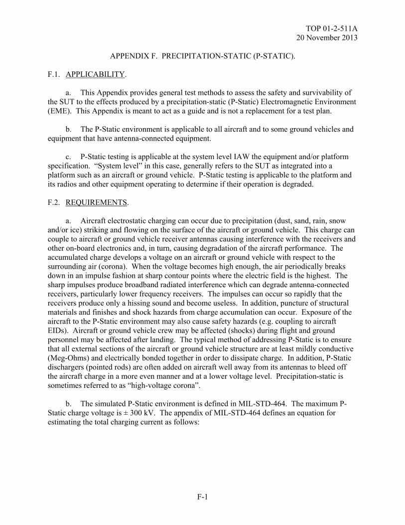
TOP 01-2-511A 20 November 2013
F-1
APPENDIX F. PRECIPITATION-STATIC (P-STATIC). F.1. APPLICABILITY. a. This Appendix provides general test methods to assess the safety and survivability of the SUT to the effects produced by a precipitation-static (P-Static) Electromagnetic Environment (EME). This Appendix is meant to act as a guide and is not a replacement for a test plan. b. The P-Static environment is applicable to all aircraft and to some ground vehicles and equipment that have antenna-connected equipment. c. P-Static testing is applicable at the system level IAW the equipment and/or platform specification. “System level” in this case, generally refers to the SUT as integrated into a platform such as an aircraft or ground vehicle. P-Static testing is applicable to the platform and its radios and other equipment operating to determine if their operation is degraded. F.2. REQUIREMENTS. a. Aircraft electrostatic charging can occur due to precipitation (dust, sand, rain, snow and/or ice) striking and flowing on the surface of the aircraft or ground vehicle. This charge can couple to aircraft or ground vehicle receiver antennas causing interference with the receivers and other on-board electronics and, in turn, causing degradation of the aircraft performance. The accumulated charge develops a voltage on an aircraft or ground vehicle with respect to the surrounding air (corona). When the voltage becomes high enough, the air periodically breaks down in an impulse fashion at sharp contour points where the electric field is the highest. The sharp impulses produce broadband radiated interference which can degrade antenna-connected receivers, particularly lower frequency receivers. The impulses can occur so rapidly that the receivers produce only a hissing sound and become useless. In addition, puncture of structural materials and finishes and shock hazards from charge accumulation can occur. Exposure of the aircraft to the P-Static environment may also cause safety hazards (e.g. coupling to aircraft EIDs). Aircraft or ground vehicle crew may be affected (shocks) during flight and ground personnel may be affected after landing. The typical method of addressing P-Static is to ensure that all external sections of the aircraft or ground vehicle structure are at least mildly conductive (Meg-Ohms) and electrically bonded together in order to dissipate charge. In addition, P-Static dischargers (pointed rods) are often added on aircraft well away from its antennas to bleed off the aircraft charge in a more even manner and at a lower voltage level. Precipitation-static is sometimes referred to as “high-voltage corona”. b. The simulated P-Static environment is defined in MIL-STD-464. The maximum P-Static charge voltage is ± 300 kV. The appendix of MIL-STD-464 defines an equation for estimating the total charging current as follows:
TOP 01-2-511A 20 November 2013
F-2
APPENDIX F. PRECIPITATION-STATIC (P-STATIC).
It = Ic x Sa × V/600 where: It = total charging current in µA Ic = charging current density in µA/m2 Sa = frontal surface area in m2 V = speed of aircraft in knots Using the MIL-STD-464C general current density data and the statement that in rare cases Ic levels as high as 400 µA/m2 have been observed, It has been calculated for various Army aircraft in Table F-1.
TABLE F-1. TOTAL CHARGING CURRENT CALCULATIONS
AIRCRAFT ESTIMATED
FRONTAL AREA (m2)
MAXIMUM SPEED (knots)
It (uA)
AH-64 Apache 7 150 420,000 OH-58D Kiowa 4 147 235,200
UH-60A Blackhawk
11 139 611,600
UH-60L Blackhawk
11 150 660,000
CH-47D Chinook 17 170 1,156,000 C-12 Huron 8 294 940,800 C-23 Sherpa 10 251 1,004,000
The results of Table F-1 indicate the maximum worst case It. Charge rates lower than this will produce the same aircraft level effects and are much easier to produce without special, more expensive test equipment. Lower charge rates (e.g., 5 mA) can therefore be used, still limited by the 300 kV level. Charging at a lower rate will take longer but will have the advantage of more accurately determining the levels at which corona, radio degradation, etc. occur. The charge will be increased to the 300 kV limit or to when discharges (streamer or arcing) occur or radio interference becomes significant, whichever occurs first. The level at which corona is observed and its locations will also be determined. c. When exposed to the P-Static environment, the SUT (and its platform, if any) shall meet the performance requirements detailed in their equipment specifications and test plan. In accordance with MIL-STD-464C, the following is required as a minimum:
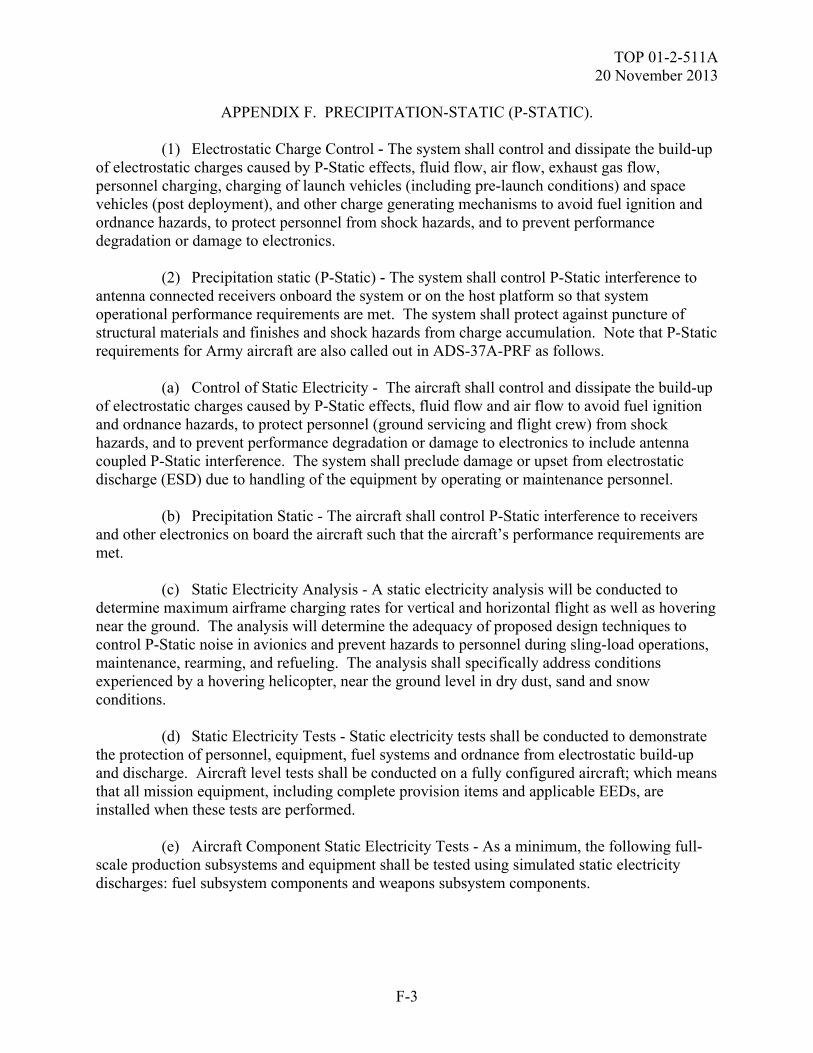
TOP 01-2-511A 20 November 2013
F-3
APPENDIX F. PRECIPITATION-STATIC (P-STATIC). (1) Electrostatic Charge Control - The system shall control and dissipate the build-up of electrostatic charges caused by P-Static effects, fluid flow, air flow, exhaust gas flow, personnel charging, charging of launch vehicles (including pre-launch conditions) and space vehicles (post deployment), and other charge generating mechanisms to avoid fuel ignition and ordnance hazards, to protect personnel from shock hazards, and to prevent performance degradation or damage to electronics. (2) Precipitation static (P-Static) - The system shall control P-Static interference to antenna connected receivers onboard the system or on the host platform so that system operational performance requirements are met. The system shall protect against puncture of structural materials and finishes and shock hazards from charge accumulation. Note that P-Static requirements for Army aircraft are also called out in ADS-37A-PRF as follows. (a) Control of Static Electricity - The aircraft shall control and dissipate the build-up of electrostatic charges caused by P-Static effects, fluid flow and air flow to avoid fuel ignition and ordnance hazards, to protect personnel (ground servicing and flight crew) from shock hazards, and to prevent performance degradation or damage to electronics to include antenna coupled P-Static interference. The system shall preclude damage or upset from electrostatic discharge (ESD) due to handling of the equipment by operating or maintenance personnel. (b) Precipitation Static - The aircraft shall control P-Static interference to receivers and other electronics on board the aircraft such that the aircraft’s performance requirements are met. (c) Static Electricity Analysis - A static electricity analysis will be conducted to determine maximum airframe charging rates for vertical and horizontal flight as well as hovering near the ground. The analysis will determine the adequacy of proposed design techniques to control P-Static noise in avionics and prevent hazards to personnel during sling-load operations, maintenance, rearming, and refueling. The analysis shall specifically address conditions experienced by a hovering helicopter, near the ground level in dry dust, sand and snow conditions. (d) Static Electricity Tests - Static electricity tests shall be conducted to demonstrate the protection of personnel, equipment, fuel systems and ordnance from electrostatic build-up and discharge. Aircraft level tests shall be conducted on a fully configured aircraft; which means that all mission equipment, including complete provision items and applicable EEDs, are installed when these tests are performed. (e) Aircraft Component Static Electricity Tests - As a minimum, the following full-scale production subsystems and equipment shall be tested using simulated static electricity discharges: fuel subsystem components and weapons subsystem components.
TOP 01-2-511A 20 November 2013
F-4
APPENDIX F. PRECIPITATION-STATIC (P-STATIC). (f) P-Static Tests - A P-Static test will be performed by electro-statically charging the aircraft until corona develops. Avionics, fuel system, flight control and other equipment will be monitored for unintentional responses linked to P-Static build-up and discharge. Charge/discharge currents will be measured. Receiver noise floors shall be monitored for degradation and the amount of degradation shall be quantified. (g) P-Static Control Tests - Testing shall be conducted to demonstrate the effectiveness of all P-Static dissipation devices on the aircraft. Results shall be used to demonstrate that the aircraft does not attain voltage potentials which are hazardous to personnel for the expected charging conditions. F.2.1 SUT performance specification requirement wording for P-Static is often different and/or more detailed than that in MIL-STD-464. Following are some typical performance requirements: a. The SUT shall remain safe and meet its performance requirements while being subjected to the P-Static environment at the system (aircraft) level. The charge limit shall be 300 kV or when discharges (streamer or arcing) occur or radio interference becomes significant. b. When the SUT contains ordnance or safety critical circuits / functions (e.g. EIDs,), the SUT ordnance and safety critical circuits / functions shall meet the safety margin requirements during and after exposure to the P-Static specification environment. The SUT EIDs, if any, will be considered to have passed when subjected to the P-Static environment, if they exhibit sufficient safety margins. There are two classifications of EID situations, safety and reliability. In accordance with MIL-STD-464, safety (hazardous) EIDs shall maintain a 16.5 dB safety factor below the MNF parameter (based on not exceeding 15% of the EID MNF) and reliability (non-hazardous) EIDs shall maintain a 6 dB safety factor below the MNF (based on not exceeding 50% of the MNF). When empirical MNFE for a specific, qualified, one-Watt no-fire EED is lacking, the Army uses a level of 17.6 mJ based on previous testing of a series of Stinger launch/flight motor EEDs. MIL-STD-1316 specifies a minimum firing voltage of 500 volts for an ESAD. A JOTP is in process and should be used for guidance of joint munition ESD and Lightning testing. c. When the SUT contains flight critical circuits / functions, the SUT flight critical circuits / functions shall operate through exposure to the P-Static specification environment without damage, upset, or degradation outside of its performance tolerances. d. When the SUT is integrated into a platform, P-Static testing is performed at the platform level. If so, the platform level requirements must also be taken into account (e.g. the SUT response to the P-Static environment must preclude upset, degradation and damage to its aircraft platform which would preclude its safe return and landing).
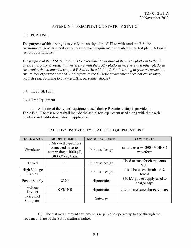
TOP 01-2-511A 20 November 2013
F-5
APPENDIX F. PRECIPITATION-STATIC (P-STATIC). F.3. PURPOSE. The purpose of this testing is to verify the ability of the SUT to withstand the P-Static environment IAW its specification performance requirements detailed in the test plan. A typical test purpose follows: The purpose of the P-Static testing is to determine if exposure of the SUT / platform to the P-Static environment results in interference with the SUT / platform receivers and other platform electronics due to antenna coupled P-Static. In addition, P-Static testing may be performed to ensure that exposure of the SUT / platform to the P-Static environment does not cause safety hazards (e.g. coupling to aircraft EIDs, personnel shocks). F.4. TEST SETUP. F.4.1 Test Equipment. a. A listing of the typical equipment used during P-Static testing is provided in Table F-2. The test report shall include the actual test equipment used along with their serial numbers and calibration dates, if applicable.
TABLE F-2. P-STATIC TYPICAL TEST EQUIPMENT LIST
HARDWARE MODEL NUMBER MANUFACTURER COMMENTS
Simulator
7 Maxwell capacitors connected in series
comprising a 1000 pF, 300 kV cap bank
In-house design simulates a +/- 300 kV HESD
waveform
Toroid --- In-house design Used to transfer charge onto
SUT High Voltage
Cables --- In-house design
Used between simulator & toroid
Power Supply 8300 Hipotronics 360 kV power supply used to
charge caps Voltage Divider
KVM400 Hipotronics Used to measure charge voltage
Personnel Computer
-- Gateway
(1) The test measurement equipment is required to operate up to and through the frequency range of the SUT / platform radios.
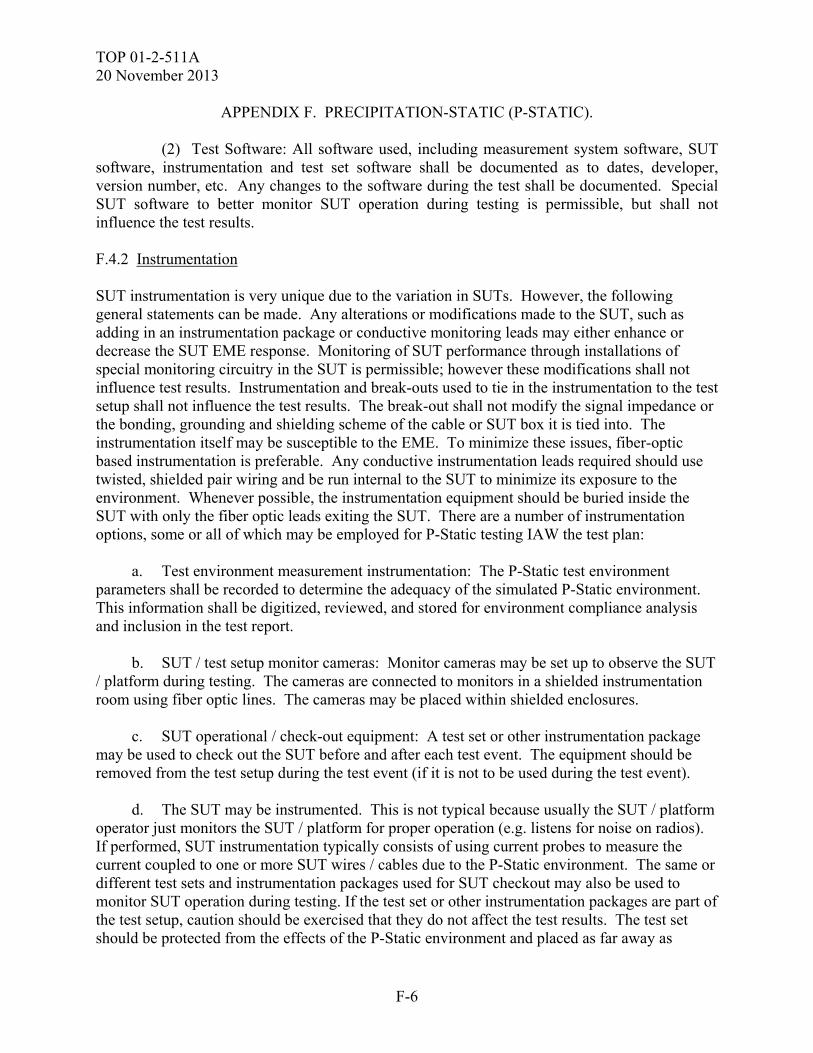
TOP 01-2-511A 20 November 2013
F-6
APPENDIX F. PRECIPITATION-STATIC (P-STATIC). (2) Test Software: All software used, including measurement system software, SUT software, instrumentation and test set software shall be documented as to dates, developer, version number, etc. Any changes to the software during the test shall be documented. Special SUT software to better monitor SUT operation during testing is permissible, but shall not influence the test results. F.4.2 Instrumentation SUT instrumentation is very unique due to the variation in SUTs. However, the following general statements can be made. Any alterations or modifications made to the SUT, such as adding in an instrumentation package or conductive monitoring leads may either enhance or decrease the SUT EME response. Monitoring of SUT performance through installations of special monitoring circuitry in the SUT is permissible; however these modifications shall not influence test results. Instrumentation and break-outs used to tie in the instrumentation to the test setup shall not influence the test results. The break-out shall not modify the signal impedance or the bonding, grounding and shielding scheme of the cable or SUT box it is tied into. The instrumentation itself may be susceptible to the EME. To minimize these issues, fiber-optic based instrumentation is preferable. Any conductive instrumentation leads required should use twisted, shielded pair wiring and be run internal to the SUT to minimize its exposure to the environment. Whenever possible, the instrumentation equipment should be buried inside the SUT with only the fiber optic leads exiting the SUT. There are a number of instrumentation options, some or all of which may be employed for P-Static testing IAW the test plan: a. Test environment measurement instrumentation: The P-Static test environment parameters shall be recorded to determine the adequacy of the simulated P-Static environment. This information shall be digitized, reviewed, and stored for environment compliance analysis and inclusion in the test report. b. SUT / test setup monitor cameras: Monitor cameras may be set up to observe the SUT / platform during testing. The cameras are connected to monitors in a shielded instrumentation room using fiber optic lines. The cameras may be placed within shielded enclosures. c. SUT operational / check-out equipment: A test set or other instrumentation package may be used to check out the SUT before and after each test event. The equipment should be removed from the test setup during the test event (if it is not to be used during the test event). d. The SUT may be instrumented. This is not typical because usually the SUT / platform operator just monitors the SUT / platform for proper operation (e.g. listens for noise on radios). If performed, SUT instrumentation typically consists of using current probes to measure the current coupled to one or more SUT wires / cables due to the P-Static environment. The same or different test sets and instrumentation packages used for SUT checkout may also be used to monitor SUT operation during testing. If the test set or other instrumentation packages are part of the test setup, caution should be exercised that they do not affect the test results. The test set should be protected from the effects of the P-Static environment and placed as far away as
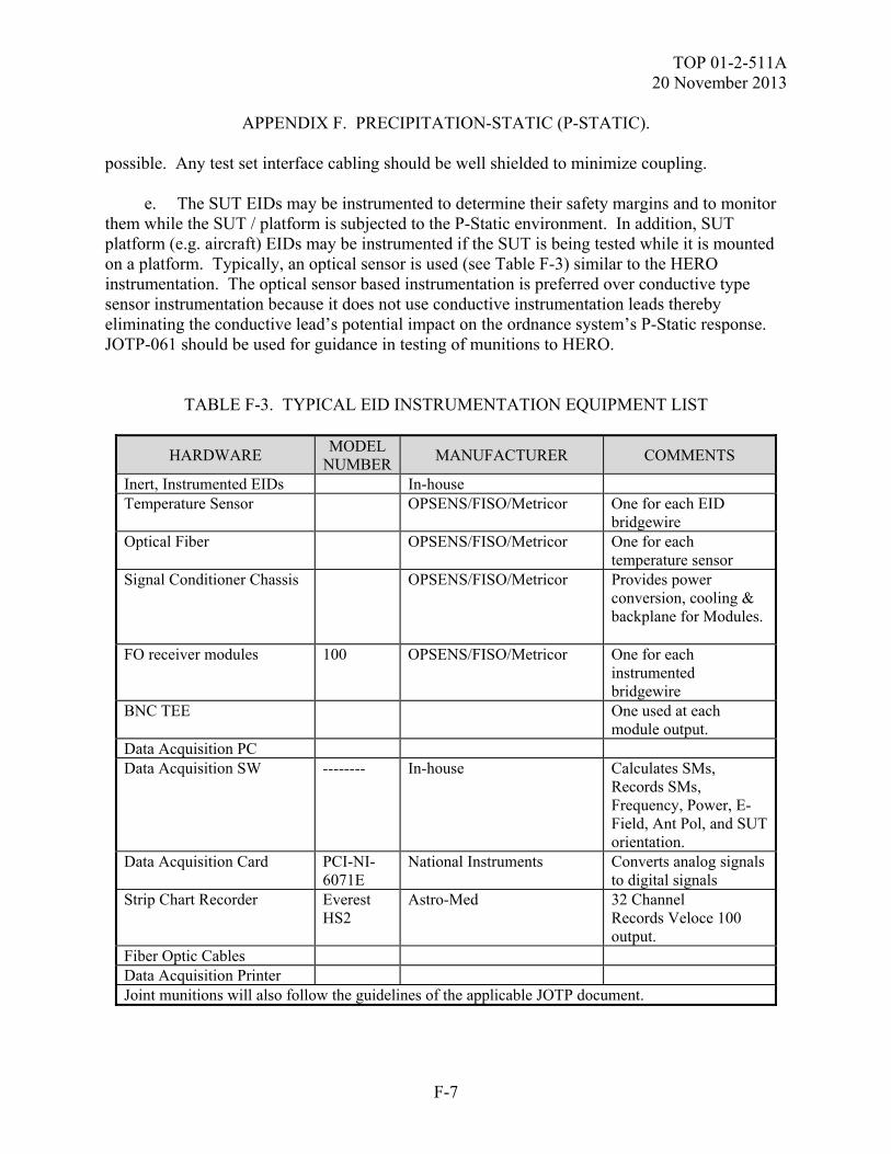
TOP 01-2-511A 20 November 2013
F-7
APPENDIX F. PRECIPITATION-STATIC (P-STATIC). possible. Any test set interface cabling should be well shielded to minimize coupling. e. The SUT EIDs may be instrumented to determine their safety margins and to monitor them while the SUT / platform is subjected to the P-Static environment. In addition, SUT platform (e.g. aircraft) EIDs may be instrumented if the SUT is being tested while it is mounted on a platform. Typically, an optical sensor is used (see Table F-3) similar to the HERO instrumentation. The optical sensor based instrumentation is preferred over conductive type sensor instrumentation because it does not use conductive instrumentation leads thereby eliminating the conductive lead’s potential impact on the ordnance system’s P-Static response. JOTP-061 should be used for guidance in testing of munitions to HERO.
TABLE F-3. TYPICAL EID INSTRUMENTATION EQUIPMENT LIST
HARDWARE MODEL
NUMBERMANUFACTURER COMMENTS
Inert, Instrumented EIDs In-house Temperature Sensor OPSENS/FISO/Metricor One for each EID
bridgewire Optical Fiber OPSENS/FISO/Metricor One for each
temperature sensor Signal Conditioner Chassis OPSENS/FISO/Metricor Provides power
conversion, cooling & backplane for Modules.
FO receiver modules 100 OPSENS/FISO/Metricor One for each instrumented bridgewire
BNC TEE One used at each module output.
Data Acquisition PC Data Acquisition SW -------- In-house Calculates SMs,
Records SMs, Frequency, Power, E-Field, Ant Pol, and SUT orientation.
Data Acquisition Card PCI-NI-6071E
National Instruments Converts analog signals to digital signals
Strip Chart Recorder Everest HS2
Astro-Med 32 Channel Records Veloce 100 output.
Fiber Optic Cables Data Acquisition Printer Joint munitions will also follow the guidelines of the applicable JOTP document.
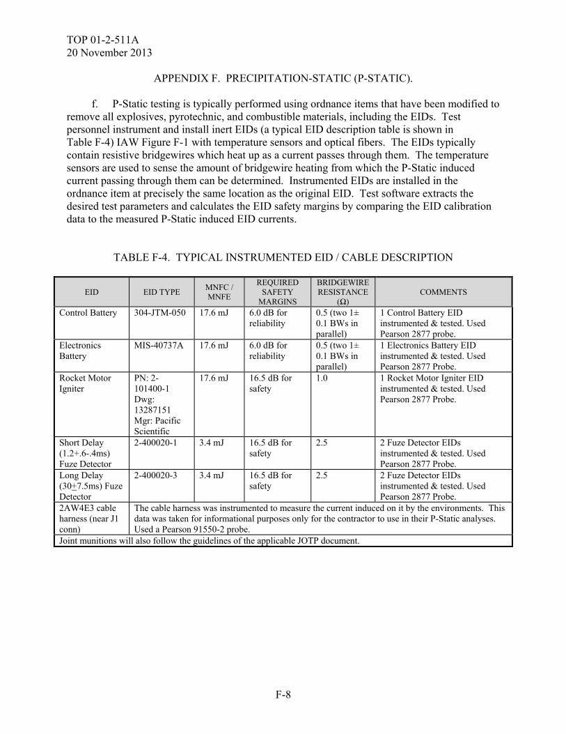
TOP 01-2-511A 20 November 2013
F-8
APPENDIX F. PRECIPITATION-STATIC (P-STATIC).
f. P-Static testing is typically performed using ordnance items that have been modified to remove all explosives, pyrotechnic, and combustible materials, including the EIDs. Test personnel instrument and install inert EIDs (a typical EID description table is shown in Table F-4) IAW Figure F-1 with temperature sensors and optical fibers. The EIDs typically contain resistive bridgewires which heat up as a current passes through them. The temperature sensors are used to sense the amount of bridgewire heating from which the P-Static induced current passing through them can be determined. Instrumented EIDs are installed in the ordnance item at precisely the same location as the original EID. Test software extracts the desired test parameters and calculates the EID safety margins by comparing the EID calibration data to the measured P-Static induced EID currents.
TABLE F-4. TYPICAL INSTRUMENTED EID / CABLE DESCRIPTION
EID EID TYPE MNFC / MNFE
REQUIRED SAFETY
MARGINS
BRIDGEWIRE RESISTANCE
(Ω) COMMENTS
Control Battery 304-JTM-050 17.6 mJ 6.0 dB for reliability
0.5 (two 1± 0.1 BWs in parallel)
1 Control Battery EID instrumented & tested. Used Pearson 2877 probe.
Electronics Battery
MIS-40737A 17.6 mJ 6.0 dB for reliability
0.5 (two 1± 0.1 BWs in parallel)
1 Electronics Battery EID instrumented & tested. Used Pearson 2877 Probe.
Rocket Motor Igniter
PN: 2-101400-1 Dwg: 13287151 Mgr: Pacific Scientific
17.6 mJ 16.5 dB for safety
1.0 1 Rocket Motor Igniter EID instrumented & tested. Used Pearson 2877 Probe.
Short Delay (1.2+.6-.4ms) Fuze Detector
2-400020-1 3.4 mJ 16.5 dB for safety
2.5 2 Fuze Detector EIDs instrumented & tested. Used Pearson 2877 Probe.
Long Delay (30+7.5ms) Fuze Detector
2-400020-3 3.4 mJ 16.5 dB for safety
2.5 2 Fuze Detector EIDs instrumented & tested. Used Pearson 2877 Probe.
2AW4E3 cable harness (near J1 conn)
The cable harness was instrumented to measure the current induced on it by the environments. This data was taken for informational purposes only for the contractor to use in their P-Static analyses. Used a Pearson 91550-2 probe.
Joint munitions will also follow the guidelines of the applicable JOTP document.
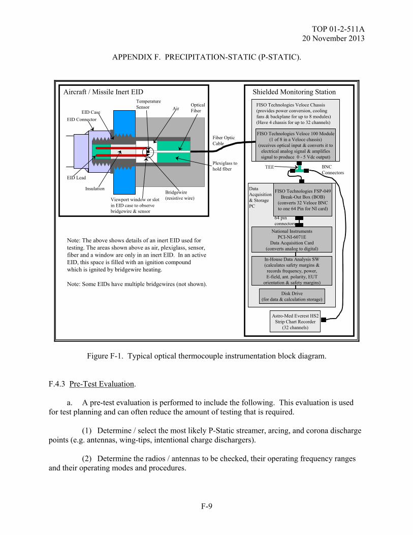
TOP 01-2-511A 20 November 2013
F-9
APPENDIX F. PRECIPITATION-STATIC (P-STATIC).
Shielded Monitoring Station
Fiber OpticCable
Aircraft / Missile Inert EIDTemperatureSensor
Bridgewire(resistive wire)
EID Connector
Insulation
EID Lead
OpticalFiber
FISO Technologies Veloce 100 Module(1 of 8 in a Veloce chassis)
(receives optical input & converts it toelectrical analog signal & amplifiessignal to produce 0 - 5 Vdc output)
FISO Technologies Veloce Chassis(provides power conversion, coolingfans & backplane for up to 8 modules)(Have 4 chassis for up to 32 channels)
BNCConnectors
Astro-Med Everest HS2Strip Chart Recorder
(32 channels)
DataAcquisition& StoragePC
National InstrumentsPCI-NI-6071E
Data Acquisition Card(converts analog to digital)
In-House Data Analysis SW(calculates safety margins &
records frequency, power,E-field, ant. polarity, EUT
orientation & safety margins)
Disk Drive(for data & calculation storage)
EID Case
Viewport window or slotin EID case to observebridgewire & sensor
Plexiglass tohold fiber
Air
Note: The above shows details of an inert EID used for testing. The areas shown above as air, plexiglass, sensor, fiber and a window are only in an inert EID. In an activeEID, this space is filled with an ignition compoundwhich is ignited by bridgewire heating.
Note: Some EIDs have multiple bridgewires (not shown).
TEE
FISO Technologies FSP-049Break-Out Box (BOB)
(converts 32 Veloce BNCto one 64 Pin for NI card)
64 pinconnectors
Figure F-1. Typical optical thermocouple instrumentation block diagram. F.4.3 Pre-Test Evaluation. a. A pre-test evaluation is performed to include the following. This evaluation is used for test planning and can often reduce the amount of testing that is required. (1) Determine / select the most likely P-Static streamer, arcing, and corona discharge points (e.g. antennas, wing-tips, intentional charge dischargers). (2) Determine the radios / antennas to be checked, their operating frequency ranges and their operating modes and procedures.
TOP 01-2-511A 20 November 2013
F-10
APPENDIX F. PRECIPITATION-STATIC (P-STATIC). (3) Determine the most / least susceptible SUT configurations. (4) Determine the most / least susceptible SUT modes of operation. (5) Determine the probable POEs. (6) Determine the bulk current measurement points. (7) Perform an energy coupling analysis to identify the type and capability requirements for the data acquisition system. (8) Determine what critical SUT data is required to be instrumented and monitored. (9) Determine which EIDs are to be instrumented and measured and how. A Joint Service E3 Safety Testing procedure is in process and should be used for guidance in testing of Joint munitions to HERO, EMP, ESD and Lightning. (10) Determine SUT / platform flight / mission / safety critical functions and circuits. (11) Determine SUT P-Static discharger protection features and their predicted performance and whether they are repairable or replaceable. Determine if and how all external sections of the aircraft structures are at least mildly conductive and electrically bonded together in order to dissipate charge. (12) Determine verification and pass/fail criteria and required safety margins. (13) Determine the SUT operating and check-out procedures. b. Pre-existing analyses and test data from previous tests may be evaluated and incorporated into the test planning and pre-test analysis in order to enhance and reduce the scope of the new testing. c. The SUT status shall be verified and documented prior to P-Static testing, using baseline Built-In-Test (BIT) checks, system operational performance checks, and functional performance measures. F.4.4 Setup. Test setups vary depending on the SUT. Some typical test setups and photographs are shown in Figures F-2 through F-6. Following are general test setup guidelines.
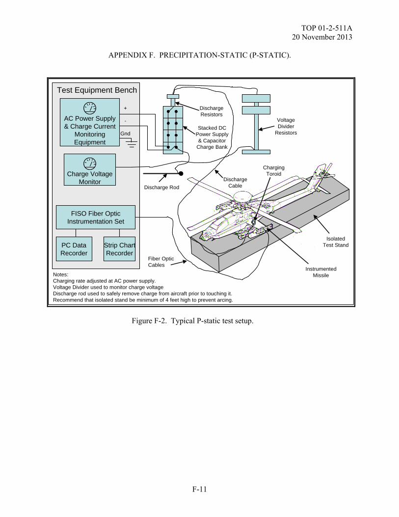
TOP 01-2-511A 20 November 2013
F-11
APPENDIX F. PRECIPITATION-STATIC (P-STATIC).
Test Equipment Bench
AC Power Supply& Charge Current
MonitoringEquipment
FISO Fiber OpticInstrumentation Set
PC DataRecorder
Strip ChartRecorder
IsolatedTest Stand
InstrumentedMissile
ChargingToroid
+
-
GndStacked DC
Power Supply& Capacitor
Charge Bank
DischargeResistors
Discharge Rod
Notes:Charging rate adjusted at AC power supply.Voltage Divider used to monitor charge voltageDischarge rod used to safely remove charge from aircraft prior to touching it.Recommend that isolated stand be minimum of 4 feet high to prevent arcing.
Fiber OpticCables
DischargeCable
Charge VoltageMonitor
VoltageDivider
Resistors
Figure F-2. Typical P-static test setup.
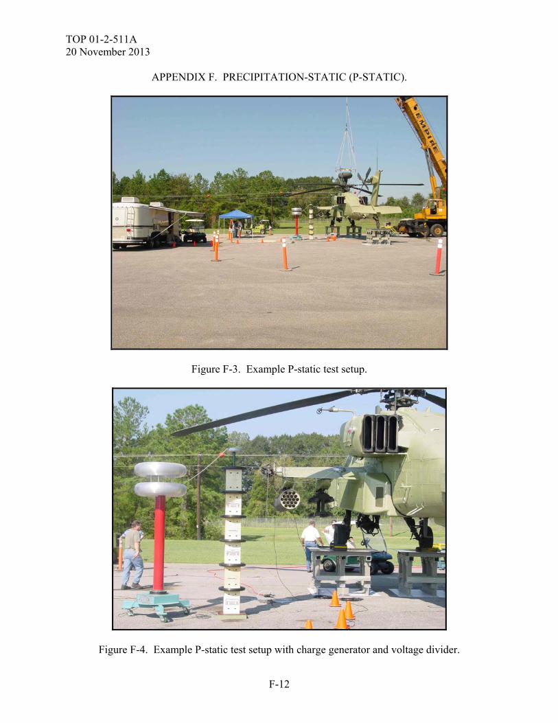
TOP 01-2-511A 20 November 2013
F-12
APPENDIX F. PRECIPITATION-STATIC (P-STATIC).
Figure F-3. Example P-static test setup.
Figure F-4. Example P-static test setup with charge generator and voltage divider.
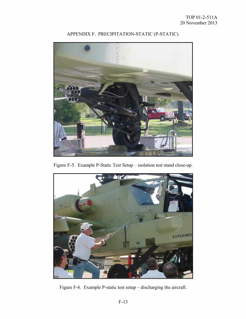
TOP 01-2-511A 20 November 2013
F-13
APPENDIX F. PRECIPITATION-STATIC (P-STATIC).
Figure F-5. Example P-Static Test Setup – isolation test stand close-up.
Figure F-6. Example P-static test setup – discharging the aircraft.
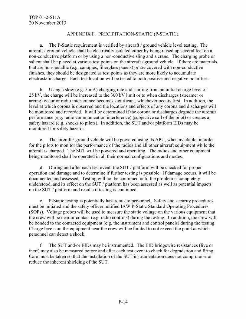
TOP 01-2-511A 20 November 2013
F-14
APPENDIX F. PRECIPITATION-STATIC (P-STATIC). a. The P-Static requirement is verified by aircraft / ground vehicle level testing. The aircraft / ground vehicle shall be electrically isolated either by being raised up several feet on a non-conductive platform or by using a non-conductive sling and a crane. The charging probe or salient shall be placed at various test points on the aircraft / ground vehicle. If there are materials that are non-metallic (e.g. canopies, fiberglass panels) or are covered with non-conductive finishes, they should be designated as test points as they are more likely to accumulate electrostatic charge. Each test location will be tested to both positive and negative polarities. b. Using a slow (e.g. 5 mA) charging rate and starting from an initial charge level of 25 kV, the charge will be increased to the 300 kV limit or to when discharges (streamer or arcing) occur or radio interference becomes significant, whichever occurs first. In addition, the level at which corona is observed and the locations and effects of any corona and discharges will be monitored and recorded. It will be determined if the corona or discharges degrade the aircraft performance (e.g. radio communication interference) (subjective call of the pilot) or creates a safety hazard (e.g. shocks to pilots). In addition, the SUT and/or platform EIDs may be monitored for safety hazards. c. The aircraft / ground vehicle will be powered using its APU, when available, in order for the pilots to monitor the performance of the radios and all other aircraft equipment while the aircraft is charged. The SUT will be powered and operating. The radios and other equipment being monitored shall be operated in all their normal configurations and modes. d. During and after each test event, the SUT / platform will be checked for proper operation and damage and to determine if further testing is possible. If damage occurs, it will be documented and assessed. Testing will not be continued until the problem is completely understood, and its effect on the SUT / platform has been assessed as well as potential impacts on the SUT / platform and results if testing is continued. e. P-Static testing is potentially hazardous to personnel. Safety and security procedures must be initiated and the safety officer notified IAW P-Static Standard Operating Procedures (SOPs). Voltage probes will be used to measure the static voltage on the various equipment that the crew will be near or contact (e.g. radio controls) during the testing. In addition, the crew will be bonded to the contacted equipment (e.g. the instrument and control panels) during the testing. Charge levels on the equipment near the crew will be limited to not exceed the point at which personnel can detect a shock. f. The SUT and/or EIDs may be instrumented. The EID bridgewire resistances (live or inert) may also be measured before and after each test event to check for degradation and firing. Care must be taken so that the installation of the SUT instrumentation does not compromise or reduce the inherent shielding of the SUT.
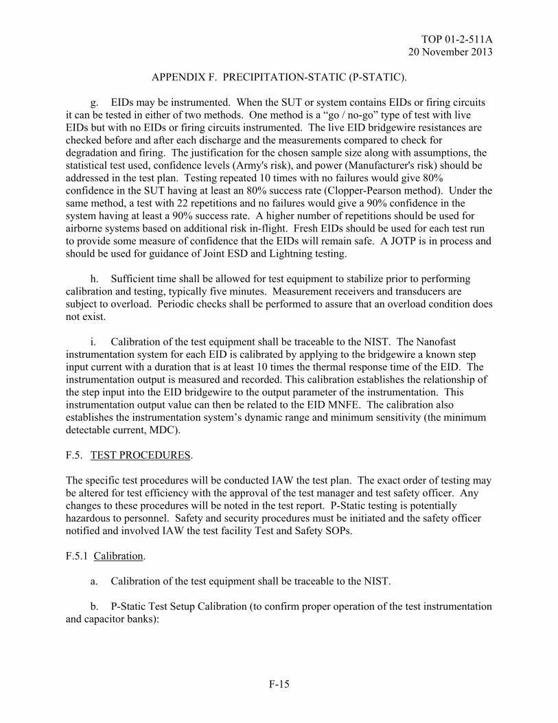
TOP 01-2-511A 20 November 2013
F-15
APPENDIX F. PRECIPITATION-STATIC (P-STATIC). g. EIDs may be instrumented. When the SUT or system contains EIDs or firing circuits it can be tested in either of two methods. One method is a “go / no-go” type of test with live EIDs but with no EIDs or firing circuits instrumented. The live EID bridgewire resistances are checked before and after each discharge and the measurements compared to check for degradation and firing. The justification for the chosen sample size along with assumptions, the statistical test used, confidence levels (Army's risk), and power (Manufacturer's risk) should be addressed in the test plan. Testing repeated 10 times with no failures would give 80% confidence in the SUT having at least an 80% success rate (Clopper-Pearson method). Under the same method, a test with 22 repetitions and no failures would give a 90% confidence in the system having at least a 90% success rate. A higher number of repetitions should be used for airborne systems based on additional risk in-flight. Fresh EIDs should be used for each test run to provide some measure of confidence that the EIDs will remain safe. A JOTP is in process and should be used for guidance of Joint ESD and Lightning testing. h. Sufficient time shall be allowed for test equipment to stabilize prior to performing calibration and testing, typically five minutes. Measurement receivers and transducers are subject to overload. Periodic checks shall be performed to assure that an overload condition does not exist. i. Calibration of the test equipment shall be traceable to the NIST. The Nanofast instrumentation system for each EID is calibrated by applying to the bridgewire a known step input current with a duration that is at least 10 times the thermal response time of the EID. The instrumentation output is measured and recorded. This calibration establishes the relationship of the step input into the EID bridgewire to the output parameter of the instrumentation. This instrumentation output value can then be related to the EID MNFE. The calibration also establishes the instrumentation system’s dynamic range and minimum sensitivity (the minimum detectable current, MDC). F.5. TEST PROCEDURES. The specific test procedures will be conducted IAW the test plan. The exact order of testing may be altered for test efficiency with the approval of the test manager and test safety officer. Any changes to these procedures will be noted in the test report. P-Static testing is potentially hazardous to personnel. Safety and security procedures must be initiated and the safety officer notified and involved IAW the test facility Test and Safety SOPs. F.5.1 Calibration. a. Calibration of the test equipment shall be traceable to the NIST. b. P-Static Test Setup Calibration (to confirm proper operation of the test instrumentation and capacitor banks):
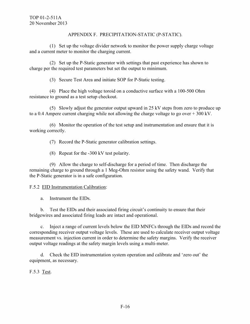
TOP 01-2-511A 20 November 2013
F-16
APPENDIX F. PRECIPITATION-STATIC (P-STATIC). (1) Set up the voltage divider network to monitor the power supply charge voltage and a current meter to monitor the charging current. (2) Set up the P-Static generator with settings that past experience has shown to charge per the required test parameters but set the output to minimum. (3) Secure Test Area and initiate SOP for P-Static testing. (4) Place the high voltage toroid on a conductive surface with a 100-500 Ohm resistance to ground as a test setup checkout. (5) Slowly adjust the generator output upward in 25 kV steps from zero to produce up to a 0.4 Ampere current charging while not allowing the charge voltage to go over + 300 kV. (6) Monitor the operation of the test setup and instrumentation and ensure that it is working correctly. (7) Record the P-Static generator calibration settings. (8) Repeat for the -300 kV test polarity. (9) Allow the charge to self-discharge for a period of time. Then discharge the remaining charge to ground through a 1 Meg-Ohm resistor using the safety wand. Verify that the P-Static generator is in a safe configuration. F.5.2 EID Instrumentation Calibration: a. Instrument the EIDs. b. Test the EIDs and their associated firing circuit’s continuity to ensure that their bridgewires and associated firing leads are intact and operational. c. Inject a range of current levels below the EID MNFCs through the EIDs and record the corresponding receiver output voltage levels. These are used to calculate receiver output voltage measurement vs. injection current in order to determine the safety margins. Verify the receiver output voltage readings at the safety margin levels using a multi-meter. d. Check the EID instrumentation system operation and calibrate and ‘zero out’ the equipment, as necessary. F.5.3 Test.
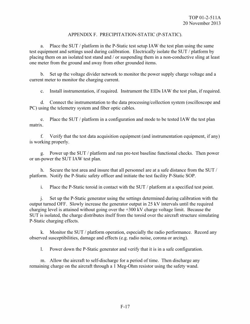
TOP 01-2-511A 20 November 2013
F-17
APPENDIX F. PRECIPITATION-STATIC (P-STATIC). a. Place the SUT / platform in the P-Static test setup IAW the test plan using the same test equipment and settings used during calibration. Electrically isolate the SUT / platform by placing them on an isolated test stand and / or suspending them in a non-conductive sling at least one meter from the ground and away from other grounded items. b. Set up the voltage divider network to monitor the power supply charge voltage and a current meter to monitor the charging current. c. Install instrumentation, if required. Instrument the EIDs IAW the test plan, if required. d. Connect the instrumentation to the data processing/collection system (oscilloscope and PC) using the telemetry system and fiber optic cables. e. Place the SUT / platform in a configuration and mode to be tested IAW the test plan matrix. f. Verify that the test data acquisition equipment (and instrumentation equipment, if any) is working properly. g. Power up the SUT / platform and run pre-test baseline functional checks. Then power or un-power the SUT IAW test plan. h. Secure the test area and insure that all personnel are at a safe distance from the SUT / platform. Notify the P-Static safety officer and initiate the test facility P-Static SOP. i. Place the P-Static toroid in contact with the SUT / platform at a specified test point. j. Set up the P-Static generator using the settings determined during calibration with the output turned OFF. Slowly increase the generator output in 25 kV intervals until the required charging level is attained without going over the +300 kV charge voltage limit. Because the SUT is isolated, the charge distributes itself from the toroid over the aircraft structure simulating P-Static charging effects. k. Monitor the SUT / platform operation, especially the radio performance. Record any observed susceptibilities, damage and effects (e.g. radio noise, corona or arcing).
l. Power down the P-Static generator and verify that it is in a safe configuration. m. Allow the aircraft to self-discharge for a period of time. Then discharge any remaining charge on the aircraft through a 1 Meg-Ohm resistor using the safety wand.
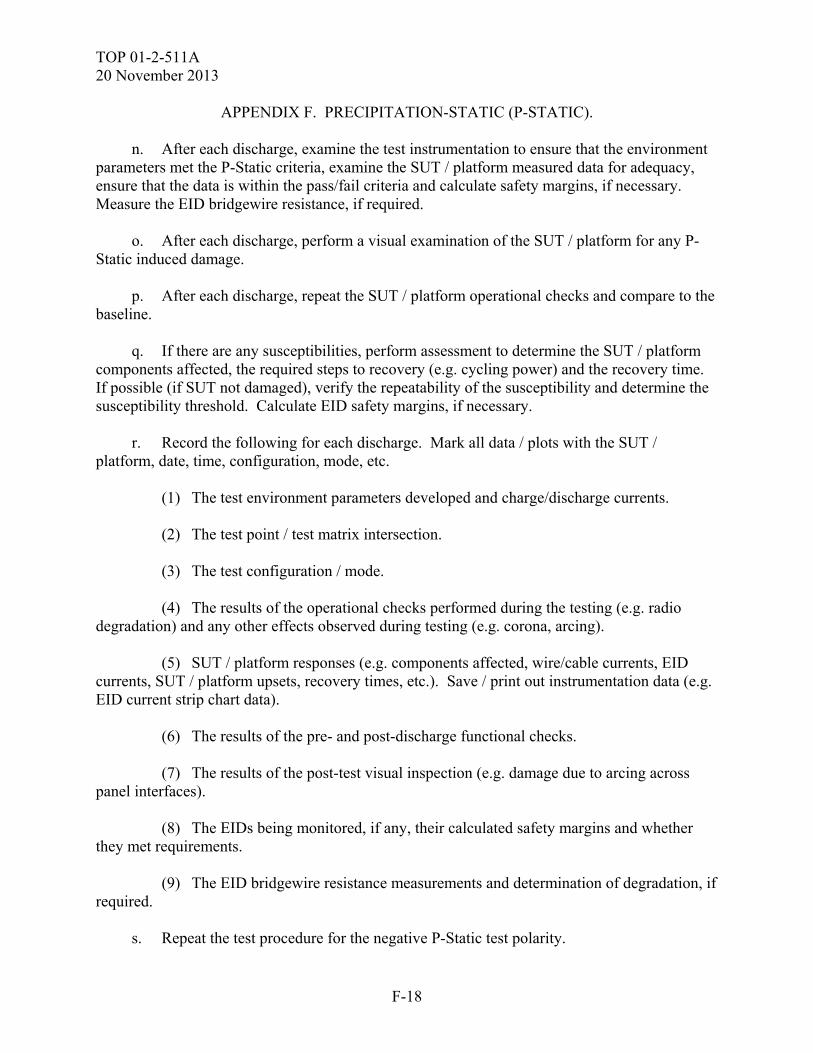
TOP 01-2-511A 20 November 2013
F-18
APPENDIX F. PRECIPITATION-STATIC (P-STATIC). n. After each discharge, examine the test instrumentation to ensure that the environment parameters met the P-Static criteria, examine the SUT / platform measured data for adequacy, ensure that the data is within the pass/fail criteria and calculate safety margins, if necessary. Measure the EID bridgewire resistance, if required. o. After each discharge, perform a visual examination of the SUT / platform for any P-Static induced damage. p. After each discharge, repeat the SUT / platform operational checks and compare to the baseline. q. If there are any susceptibilities, perform assessment to determine the SUT / platform components affected, the required steps to recovery (e.g. cycling power) and the recovery time. If possible (if SUT not damaged), verify the repeatability of the susceptibility and determine the susceptibility threshold. Calculate EID safety margins, if necessary. r. Record the following for each discharge. Mark all data / plots with the SUT / platform, date, time, configuration, mode, etc. (1) The test environment parameters developed and charge/discharge currents. (2) The test point / test matrix intersection. (3) The test configuration / mode. (4) The results of the operational checks performed during the testing (e.g. radio degradation) and any other effects observed during testing (e.g. corona, arcing). (5) SUT / platform responses (e.g. components affected, wire/cable currents, EID currents, SUT / platform upsets, recovery times, etc.). Save / print out instrumentation data (e.g. EID current strip chart data). (6) The results of the pre- and post-discharge functional checks. (7) The results of the post-test visual inspection (e.g. damage due to arcing across panel interfaces). (8) The EIDs being monitored, if any, their calculated safety margins and whether they met requirements. (9) The EID bridgewire resistance measurements and determination of degradation, if required. s. Repeat the test procedure for the negative P-Static test polarity.
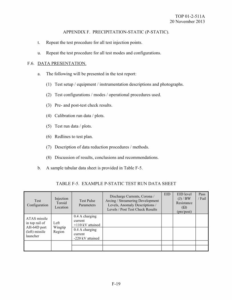
TOP 01-2-511A 20 November 2013
F-19
APPENDIX F. PRECIPITATION-STATIC (P-STATIC). t. Repeat the test procedure for all test injection points. u. Repeat the test procedure for all test modes and configurations. F.6. DATA PRESENTATION. a. The following will be presented in the test report: (1) Test setup / equipment / instrumentation descriptions and photographs. (2) Test configurations / modes / operational procedures used. (3) Pre- and post-test check results. (4) Calibration run data / plots. (5) Test run data / plots. (6) Redlines to test plan. (7) Description of data reduction procedures / methods. (8) Discussion of results, conclusions and recommendations. b. A sample tabular data sheet is provided in Table F-5.
TABLE F-5. EXAMPLE P-STATIC TEST RUN DATA SHEET
Test Configuration
Injection Toroid
Location
Test Pulse Parameters
Discharge Currents, Corona / Arcing / Streamering Development
Levels, Anomaly Descriptions / Levels / Post Test Check Results
EID EID level (J) / BW
Resistance (Ω)
(pre/post)
Pass / Fail
ATAS missile in top rail of AH-64D port (left) missile launcher
Left Wingtip Region
0.4 A charging current +110 kV attained
0.4 A charging current -220 kV attained
TOP 01-2-511A 20 November 2013
F-20
APPENDIX F. PRECIPITATION-STATIC (P-STATIC). F.7. DATA ANALYSIS. A Joint Service E3 Safety Testing procedure is in process and should be used for guidance in testing of Joint munitions to HERO, EMP, ESD and Lightning. The safety margins are calculated using the following formulas:
CURRENT: SM (dB) = 20 log10 (IMNF / IInduced) where IMNF = Maximum No-Fire current of EID (A) Iinduced = measured value for the induced EID current (A)
(or Minimum Discernible Current, MDC, if signal below MDC)
VOLTAGE: SM (dB) = 20 log10 (MFV / VInduced) where MFV = Min ESAD capacitor Firing Voltage. Typically 500 Volts 1 Vinduced = measured value for the induced ESAD cap firing voltage
(or Minimum Discernible Voltage, MDV, if signal below MDV)
ENERGY: SM (dB) = 10 log10 (EMNF / EInduced) where EMNF = Max No-Fire EID energy. Typically 17.6 milli-Joules 2 Einduced = measured energy induced in the EID circuit (J) NOTE (1) - MIL-STD-1316 requirement for minimum firing voltage = 500 volts. Most initiators have minimum firing voltages in the 1000 to 2000 volt range. NOTE (2) - Previous test programs have used 17.6 milli-Joules as the MNFE for safety margin calculations for MIL-DTL 23659 qualified, one watt, no-fire initiators. The MNFE value was established during testing of a series of Stinger Launch/Flight motor EIDs. The EID testing evaluated 72 initiators tested with a one amp per millisecond current ramp. The data was used to derive the MNFE and is documented in technical document RD-TE-87-4, MLRS AT2 Lightning Test Report. The test data will be compared to the applicable criteria set forth in MIL-STD 464C, the SUT specification, and SUT test plan and the pre-event baseline measurements to determine the extent to which the test criteria are met and the effects of the HESD test environment on the SUT. Test anomalies will be assessed to determine if they should be classified as SUT failures and if so, further assessed with regards to causes, test parameters at which they occurred, mission impact and safety. Safety margins will be calculated and compared to the criteria, as necessary.
TOP 01-2-511A 20 November 2013
G-1
APPENDIX G. HAZARDS OF ELECTROMAGNETIC RADIATION TO FUEL (HERF). G.1. APPLICABILITY.
a. Radiated HERF test - This test method is applicable to equipment at the system level IAW the equipment specification. To provide the method to assess the survivability of a system with on-board fuel to the effects produced by its operational electromagnetic environment, with a 6 dB safety margin. b. Assessment based on Hazards of Electromagnetic Radiation to Personnel (HERP) test. Provide guidance on the methods of a HERF safety assessment based on the specific system characterization parameters of frequency, and transmitter power measured and the guidelines of Naval Sea Systems Operation (NAVSEA OP) 3565 Volume I Sixth Revision18, Chapter 6. G.2. REQUIREMENTS. a. The SUT must remain safe and perform its mission essential functions during and/or after exposure to the systems operational electromagnetic environment, as specified in the system requirement document. b. The EME is produced by the system itself and co-located equipment both friendly and hostile. c. The test parameters are to be extracted from the applicable table in MIL-STD-464. Fuels shall not be inadvertently ignited by radiated EMEs. The EME includes onboard emitters and the external EME. Compliance shall be verified by test, analysis, inspection, or a combination thereof.” d. Utilize the methods of assessment from NAVSEA OP 3565 a Hazards of Electromagnetic Radiation to Personnel (HERP) test is necessary, as well as provision of the system emitter 1494s for the required analysis. G.3. PURPOSE. The purpose of this test procedure is to verify the ability of the SUT while carrying fuel to withstand the required operational environment with a 6 dB safety margin applied and/or to provide a HERF assessment with the methods of NAVSEA OP 3565. G.3.1 Physical Nature of Combustion. The probability of ignition of fuel vapors by RF-induced arcs is small, since the following conditions must occur simultaneously for ignition to take place: (1) A flammable fuel-air mixture must be present within range of the induced arcing.
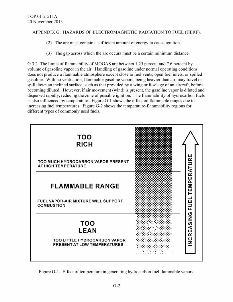
TOP 01-2-511A 20 November 2013
G-2
APPENDIX G. HAZARDS OF ELECTROMAGNETIC RADIATION TO FUEL (HERF). (2) The arc must contain a sufficient amount of energy to cause ignition. (3) The gap across which the arc occurs must be a certain minimum distance. G.3.2 The limits of flammability of MOGAS are between 1.25 percent and 7.6 percent by volume of gasoline vapor in the air. Handling of gasoline under normal operating conditions does not produce a flammable atmosphere except close to fuel vents, open fuel inlets, or spilled gasoline. With no ventilation, flammable gasoline vapors, being heavier than air, may travel or spill down an inclined surface, such as that provided by a wing or fuselage of an aircraft, before becoming diluted. However, if air movement (wind) is present, the gasoline vapor is diluted and dispersed rapidly, reducing the zone of possible ignition. The flammability of hydrocarbon fuels is also influenced by temperature. Figure G-1 shows the effect on flammable ranges due to increasing fuel temperatures. Figure G-2 shows the temperature-flammability regions for different types of commonly used fuels.
Figure G-1. Effect of temperature in generating hydrocarbon fuel flammable vapors.
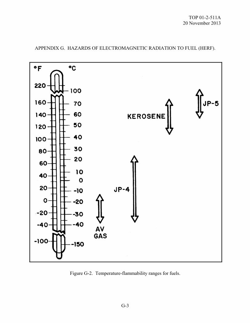
TOP 01-2-511A 20 November 2013
G-3
APPENDIX G. HAZARDS OF ELECTROMAGNETIC RADIATION TO FUEL (HERF).
Figure G-2. Temperature-flammability ranges for fuels.
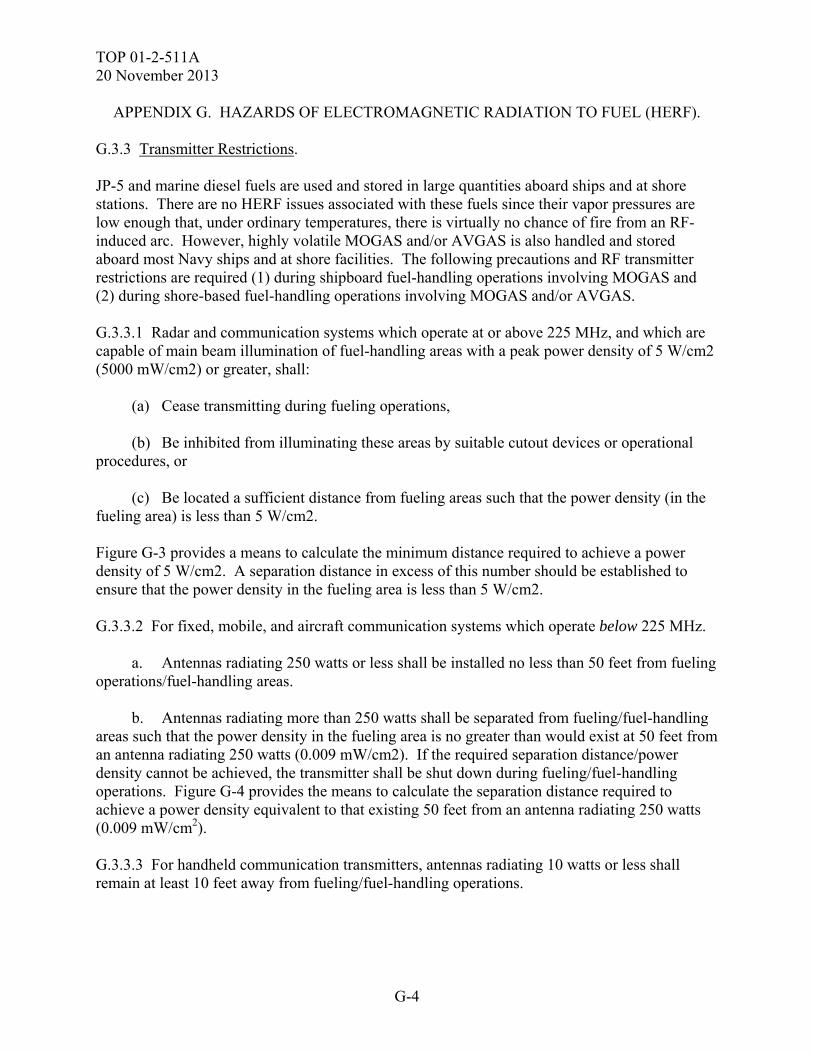
TOP 01-2-511A 20 November 2013
G-4
APPENDIX G. HAZARDS OF ELECTROMAGNETIC RADIATION TO FUEL (HERF).
G.3.3 Transmitter Restrictions. JP-5 and marine diesel fuels are used and stored in large quantities aboard ships and at shore stations. There are no HERF issues associated with these fuels since their vapor pressures are low enough that, under ordinary temperatures, there is virtually no chance of fire from an RF-induced arc. However, highly volatile MOGAS and/or AVGAS is also handled and stored aboard most Navy ships and at shore facilities. The following precautions and RF transmitter restrictions are required (1) during shipboard fuel-handling operations involving MOGAS and (2) during shore-based fuel-handling operations involving MOGAS and/or AVGAS. G.3.3.1 Radar and communication systems which operate at or above 225 MHz, and which are capable of main beam illumination of fuel-handling areas with a peak power density of 5 W/cm2 (5000 mW/cm2) or greater, shall: (a) Cease transmitting during fueling operations, (b) Be inhibited from illuminating these areas by suitable cutout devices or operational procedures, or (c) Be located a sufficient distance from fueling areas such that the power density (in the fueling area) is less than 5 W/cm2. Figure G-3 provides a means to calculate the minimum distance required to achieve a power density of 5 W/cm2. A separation distance in excess of this number should be established to ensure that the power density in the fueling area is less than 5 W/cm2. G.3.3.2 For fixed, mobile, and aircraft communication systems which operate below 225 MHz. a. Antennas radiating 250 watts or less shall be installed no less than 50 feet from fueling operations/fuel-handling areas. b. Antennas radiating more than 250 watts shall be separated from fueling/fuel-handling areas such that the power density in the fueling area is no greater than would exist at 50 feet from an antenna radiating 250 watts (0.009 mW/cm2). If the required separation distance/power density cannot be achieved, the transmitter shall be shut down during fueling/fuel-handling operations. Figure G-4 provides the means to calculate the separation distance required to achieve a power density equivalent to that existing 50 feet from an antenna radiating 250 watts (0.009 mW/cm2). G.3.3.3 For handheld communication transmitters, antennas radiating 10 watts or less shall remain at least 10 feet away from fueling/fuel-handling operations.
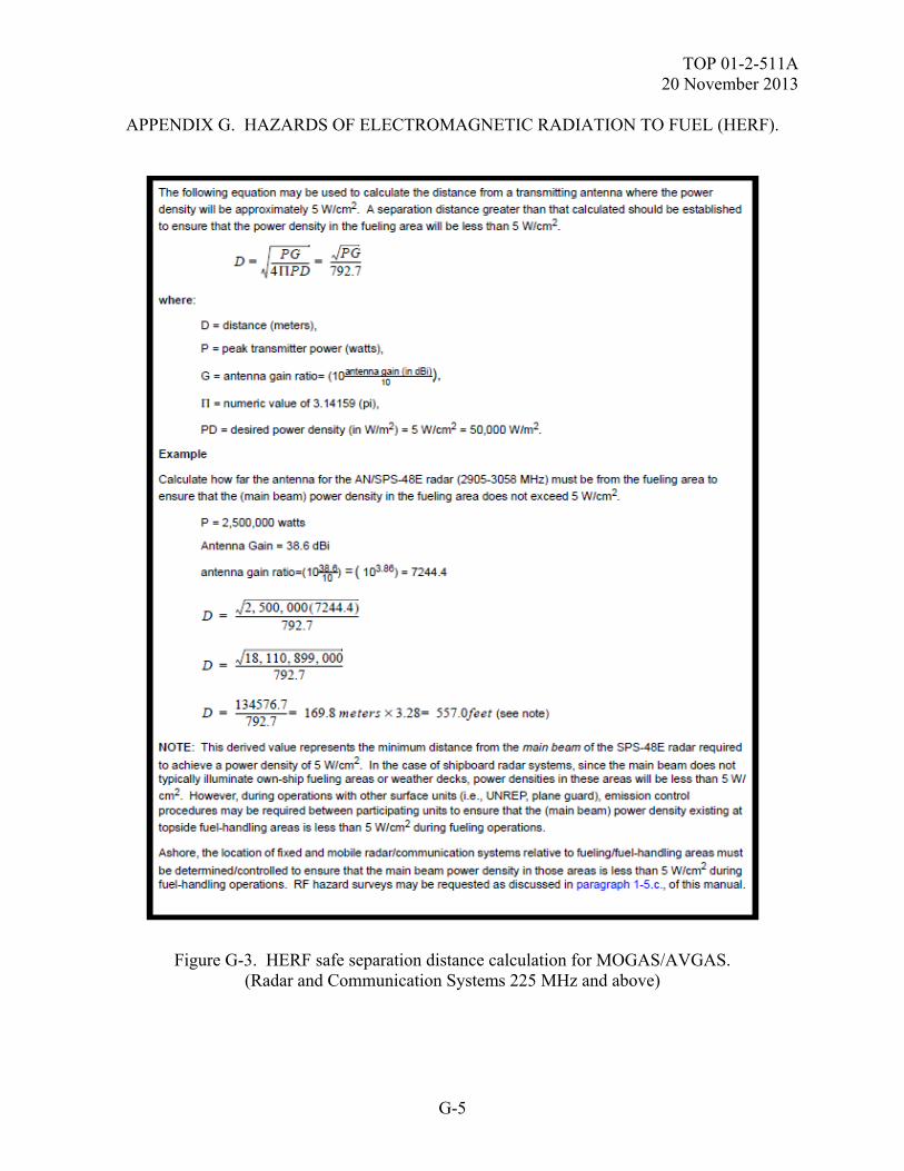
TOP 01-2-511A 20 November 2013
G-5
APPENDIX G. HAZARDS OF ELECTROMAGNETIC RADIATION TO FUEL (HERF).
Figure G-3. HERF safe separation distance calculation for MOGAS/AVGAS. (Radar and Communication Systems 225 MHz and above)
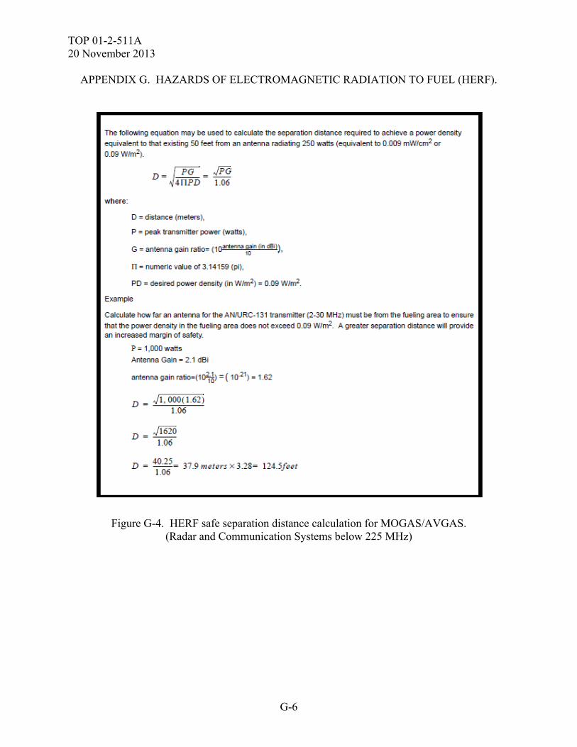
TOP 01-2-511A 20 November 2013
G-6
APPENDIX G. HAZARDS OF ELECTROMAGNETIC RADIATION TO FUEL (HERF).
Figure G-4. HERF safe separation distance calculation for MOGAS/AVGAS. (Radar and Communication Systems below 225 MHz)
TOP 01-2-511A 20 November 2013
G-7
APPENDIX G. HAZARDS OF ELECTROMAGNETIC RADIATION TO FUEL (HERF). G.4. TEST SET UP. G.4.1 Test Equipment. a. Radiated HERF test - The typical equipment used in performing a HERF test on a system fueled are the same high power transmitters used during operational testing, with the output increased to include the 6 dB safety margin. This testing is relatively straight forward while using one of the safest fuels JP8. For more volatile fuels extreme measures may be required to protect test assets and personnel. For volatile fuels the containers may require evacuation and the introduction of fiber optics connected to a camera to monitor for sparks and arcs. The evacuation procedures should include but is not limited to the following; 1) the fuel container is completely filled, 2) nitrogen gas (inert) is applied to the container under positive pressure and flow, 3) the fuel is drained from the system as nitrogen is used to fill the void created, 4) nitrogen flow is continuous and provides positive pressure to insure the evacuation the fuel container. b. Assessment based on HERP test - The typical equipment used in performing a HERP test on the full system with onboard emitters includes field measurement probes/antennas, spectrum analyzer, data collection computer and all applicable cabling, couplers and attenuators. G.4.2 Pre-Test Evaluation. a. A pre-test evaluation will be performed to determine the primary fuel and if special precautions and methods are required. b. The SUT status is verified and documented before HERF testing, using baseline self-test checks, system operational performance checks, and functional performance measures. c. The system emitters parameters and the 1494s shall be provided prior to test conduct to prep for HERP testing and HERF analysis. G.4.3 Setup. a. Radiated HERF test. (1) The test facility is calibrated at the radial test distance required to provide the operational EME with 6dB margin. (2) The SUT is tested in minimum of four orientations with respect to the poynting vector, i.e., all four sides with special attention to the fuel container areas. (3) The SUT is instrumented and nitrogen purged, when extremely volatile fuel is used. Care must be taken so that the installation of the spark and arc detector, does not create an electrical path into the fuel container and that a positive pressure nitrogen purge is maintained.
TOP 01-2-511A 20 November 2013
G-8
APPENDIX G. HAZARDS OF ELECTROMAGNETIC RADIATION TO FUEL (HERF). (4) The SUT is illuminated by the EME. b. Assessment based on HERP test c. Prior to placing sensor in the RF electric field, the test volume area will be measured to record field levels at ambient power levels. d. The SUT status will be verified before testing, using baseline self-test checks and system operational checks. All power density measurements will be performed while the SUT is powered ON and transmitting. e. The SUT will be powered and sufficient time allowed for stabilization and performance of the system checks. f. Throughout each HERF illumination or HERP data collection, the SUT will be fully operational, in accordance with SUT operating procedures. G.5. PROCEDURES. a. Radiated HERF Test (1) Illuminate the SUT in various orientations (0, 90, 180 and 270 degrees). See External RF EME, Appendix B. (2) Monitor the fuel for ignition, or monitor the instrumentation for light created in the fuel container by sparks or arcs. (3) Any problems that occur will be documented. Testing will not continue until the problem is understood and its effects on the SUT are assessed. b. Assessment based on HERP test. c. A calibrated power density meter (PDM) shall be utilized to perform the measurements on the UUT. This meter measures the average radiated power density in mW/cm2. For modulated transmitters this may not capture a noticeable measurement. A spectrum analyzer and antenna may be used to capture the actual transmission from the transmitter if necessary for functional confirmation and measurement of peak fields. d. The power meter will be placed in the RF field and data collected at various heights above ground level and various distances/positions around the SUT antennae. The PDM will initially be placed 1.5 meters above ground level. Levels may be monitored starting at 10 meters from SUT as a baseline and moving in at increments of 1 meter if a worst case position is not easily found.
TOP 01-2-511A 20 November 2013
G-9
APPENDIX G. HAZARDS OF ELECTROMAGNETIC RADIATION TO FUEL (HERF). e. The SUT status will be verified before testing, using baseline self-test checks and system operational checks. All power density measurements will be performed while the SUT is powered ON and transmitting and sufficient time allowed for stabilization and performance of the system checks. f. Data for the SUT will be recorded for later processing and analysis, and checked for validity. g. Steps e and f will be repeated for each SUT measurement location at various increments 360 degrees around the UUT. Four measurement locations should be utilized at a minimum. h. After data has been collected at the predetermined position the worst case positions will be identified and the PDM will be moved incrementally closer from the worst cast positions to the SUT until the HERF criteria limit for the applicable SUT operating frequency has been achieved. This distance will then be used as the actual measured minimum standoff for the SUT hazard. i. Document the failures and corrective actions. G.6. DATA PRESENTATION. a. Photos of the test setup and position. b. Typical photos of instrumentation.
G.7. DATA ANALYSIS.
a. The EME data obtained from the EME Facility will be corrected to account for the percent error associated with the calibration system. The environment data will be compared and evaluated against the systems required criteria. b. Compliance will be met if no fuel hazards are created during the radiated HERF testing based on the system performance. c. Compliance will be met if no fuel hazards are recorded during the HERP test based on the system emitter power. d. Degradation cause(s) will be identified and impact(s) on the system’s mission will be discussed. e. The system checkouts, environmental data, and test results will be processed and provided in graphical or table format.
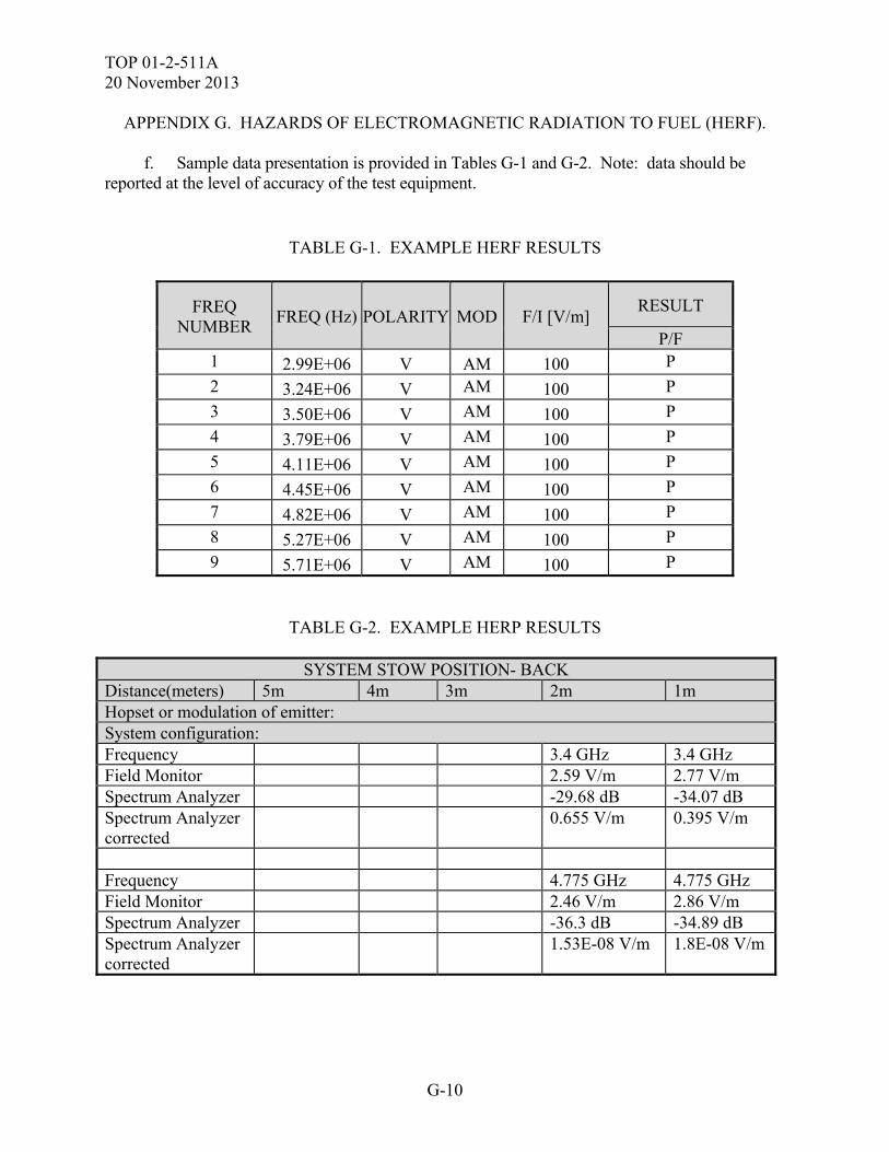
TOP 01-2-511A 20 November 2013
G-10
APPENDIX G. HAZARDS OF ELECTROMAGNETIC RADIATION TO FUEL (HERF). f. Sample data presentation is provided in Tables G-1 and G-2. Note: data should be reported at the level of accuracy of the test equipment.
TABLE G-1. EXAMPLE HERF RESULTS
FREQ NUMBER
FREQ (Hz) POLARITY MOD F/I [V/m] RESULT
P/F 1 2.99E+06 V AM 100 P
2 3.24E+06 V AM 100 P
3 3.50E+06 V AM 100 P
4 3.79E+06 V AM 100 P
5 4.11E+06 V AM 100 P
6 4.45E+06 V AM 100 P
7 4.82E+06 V AM 100 P
8 5.27E+06 V AM 100 P
9 5.71E+06 V AM 100 P
TABLE G-2. EXAMPLE HERP RESULTS
SYSTEM STOW POSITION- BACK Distance(meters) 5m 4m 3m 2m 1m Hopset or modulation of emitter: System configuration: Frequency 3.4 GHz 3.4 GHz Field Monitor 2.59 V/m 2.77 V/m Spectrum Analyzer -29.68 dB -34.07 dB Spectrum Analyzer corrected
0.655 V/m 0.395 V/m
Frequency 4.775 GHz 4.775 GHz Field Monitor 2.46 V/m 2.86 V/m Spectrum Analyzer -36.3 dB -34.89 dB Spectrum Analyzer corrected
1.53E-08 V/m 1.8E-08 V/m
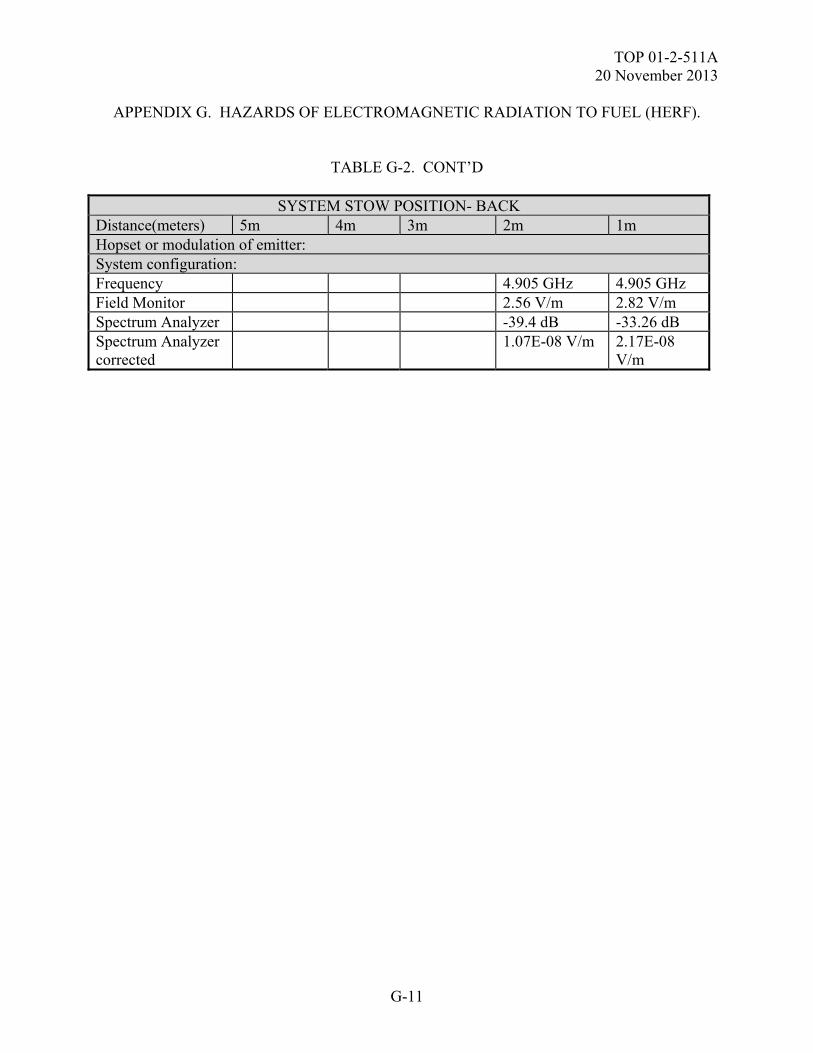
TOP 01-2-511A 20 November 2013
G-11
APPENDIX G. HAZARDS OF ELECTROMAGNETIC RADIATION TO FUEL (HERF).
TABLE G-2. CONT’D
SYSTEM STOW POSITION- BACK Distance(meters) 5m 4m 3m 2m 1m Hopset or modulation of emitter: System configuration: Frequency 4.905 GHz 4.905 GHz Field Monitor 2.56 V/m 2.82 V/m Spectrum Analyzer -39.4 dB -33.26 dB Spectrum Analyzer corrected
1.07E-08 V/m 2.17E-08 V/m

TOP 01-2-511A 20 November 2013
G-12
(This page is intentionally blank.)
TOP 01-2-511A 20 November 2013
H-1
APPENDIX H. HAZARDS OF ELECTROMAGNETIC RADIATION TO ORDNANCE (HERO).
H.1. APPLICABILITY. a. This test method is applicable to equipment at the system level IAW the equipment specification. It is to provide the methods to assess the survivability of the SUT EIDs to the required HERO Electromagnetic Environment (EME) for the platform in all phases of the stockpile to launch sequence. This Appendix is meant to act as a guide and is not a replacement for a test plan. Compliance shall be verified by system-level test, analysis, or a combination thereof. b. The ultimate objective is to provide supporting data, analysis, and reports relative to the suitability of the SUT’s EIDs for use in its battlefield transportation to tactical electromagnetic environment (stockpile to launch sequence configurations) with respect to the MIL-STD-464 HERO requirements. c. Determine the Maximum No-Fire Stimulus (MNFS) safety or reliability margin as applicable (16.5 dB for safety and 6 dB for reliability); and the Maximum Allowable Environment (MAE) for the SUT. d. To establish the SUT data for inclusion into the Joint Ordnance Electromagnetic Risk Assessment Database (JOERAD). H.2. REQUIREMENTS. a. The SUT’s EIDs shall be exposed and assessed to determine whether: the EIDs shall not inadvertently actuate, or experience degraded performance characteristics after exposure to the external EME levels of Table H-1 for both, direct Radio Frequency (RF) induced actuation of the EID and inadvertent activation of an electrically powered firing circuit as stated in MIL-STD-464C. It should also be noted that there are separate EME requirements for Army rotorcraft operations, the onboard ordnance should also comply with that EME. If threat levels cannot be achieved, a minimum field level of 200 V/m will be provided and then the instrumentation responses extrapolated to threat criteria level. MIL-HDBK-240A delineates HERO test procedures and methodology as well as maximum extrapolation values. There is also an EMROH (old term) environment for Army that denotes that time just prior to launch where electrically powered firing circuits are active; at this point the ground system EME has a 6 dB margin placed on it for reliability of ordnance. It this item is carried by a person then the item should be tested at no less than 200 V/m for operations. b. Ordnance shall have a margin of at least 16.5 dB of MNFS for safety consequences and 6 dB of MNFS for reliability consequences, as well as safety critical functions. A prematurely ignited EID that results in injury to personnel or destruction of property must meet a safety assurance margin of 16.5 dB to the MNFS. Prematurely ignited EIDs that result in unacceptable degradation in SUT performance must meet a safety margin of 6 dB to the MNFS.
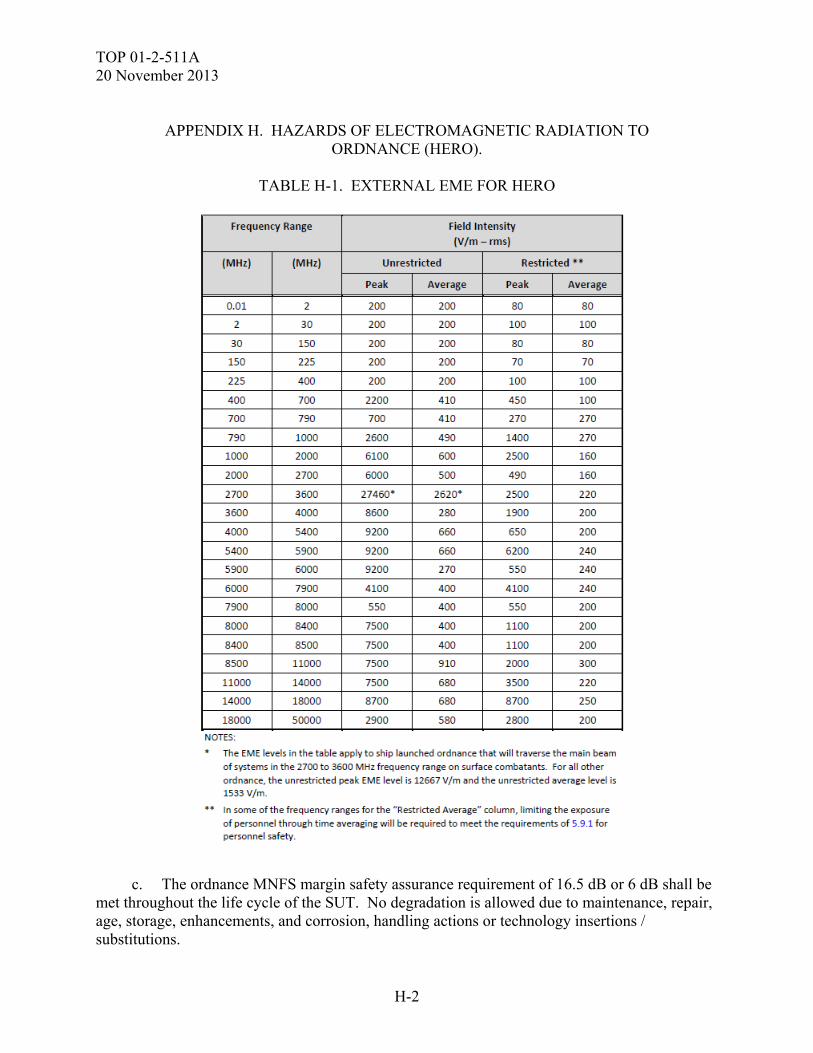
TOP 01-2-511A 20 November 2013
H-2
APPENDIX H. HAZARDS OF ELECTROMAGNETIC RADIATION TO
ORDNANCE (HERO).
TABLE H-1. EXTERNAL EME FOR HERO
c. The ordnance MNFS margin safety assurance requirement of 16.5 dB or 6 dB shall be met throughout the life cycle of the SUT. No degradation is allowed due to maintenance, repair, age, storage, enhancements, and corrosion, handling actions or technology insertions / substitutions.
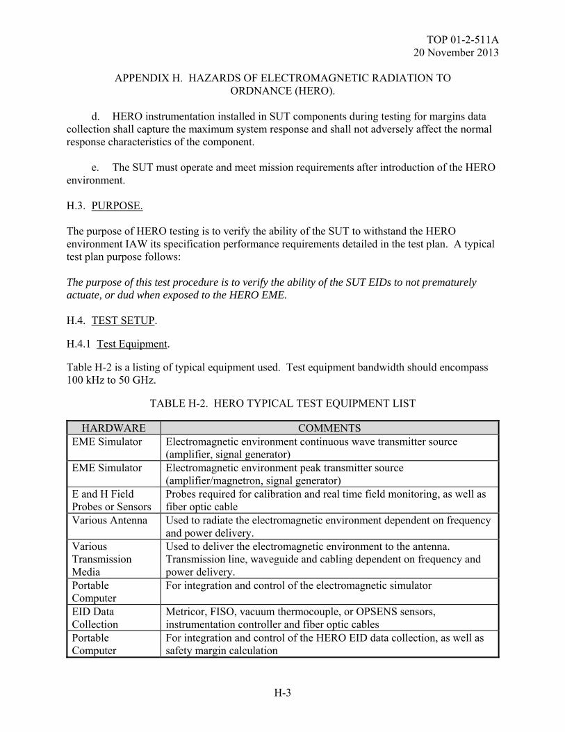
TOP 01-2-511A 20 November 2013
H-3
APPENDIX H. HAZARDS OF ELECTROMAGNETIC RADIATION TO ORDNANCE (HERO).
d. HERO instrumentation installed in SUT components during testing for margins data collection shall capture the maximum system response and shall not adversely affect the normal response characteristics of the component. e. The SUT must operate and meet mission requirements after introduction of the HERO environment. H.3. PURPOSE. The purpose of HERO testing is to verify the ability of the SUT to withstand the HERO environment IAW its specification performance requirements detailed in the test plan. A typical test plan purpose follows: The purpose of this test procedure is to verify the ability of the SUT EIDs to not prematurely actuate, or dud when exposed to the HERO EME. H.4. TEST SETUP. H.4.1 Test Equipment. Table H-2 is a listing of typical equipment used. Test equipment bandwidth should encompass 100 kHz to 50 GHz.
TABLE H-2. HERO TYPICAL TEST EQUIPMENT LIST
HARDWARE COMMENTS EME Simulator Electromagnetic environment continuous wave transmitter source
(amplifier, signal generator) EME Simulator Electromagnetic environment peak transmitter source
(amplifier/magnetron, signal generator) E and H Field Probes or Sensors
Probes required for calibration and real time field monitoring, as well as fiber optic cable
Various Antenna Used to radiate the electromagnetic environment dependent on frequency and power delivery.
Various Transmission Media
Used to deliver the electromagnetic environment to the antenna. Transmission line, waveguide and cabling dependent on frequency and power delivery.
Portable Computer
For integration and control of the electromagnetic simulator
EID Data Collection
Metricor, FISO, vacuum thermocouple, or OPSENS sensors, instrumentation controller and fiber optic cables
Portable Computer
For integration and control of the HERO EID data collection, as well as safety margin calculation
TOP 01-2-511A 20 November 2013
H-4
APPENDIX H. HAZARDS OF ELECTROMAGNETIC RADIATION TO ORDNANCE (HERO).
H.4.2 Pre-Test Evaluation. a. Prior to the start of the test, the operators shall verify that all personnel are aware of the safety aspects associated with high intensity radiated fields and that all personnel have been briefed on this subject. The MPE of DODI 6055.11 will be strictly adhered to during the test. Due to the intense levels and the fact that most operations are verified under External RF EME Testing, there will be a need for personnel to enter the EME during this subtest during the handling/loading phase (only up to 1 GHz). When necessary for monitoring/functioning of firing circuits or conduct of handling/loading operations the restricted HERO levels will apply and be utilized for those operations. b. A pre-test evaluation will be performed to determine the primary current paths, port of entries, test orientations and configurations, and test conditions for the SUT. The bare EID test configuration may be assumed to be worst case for energy transfer to the ordnance itself due to the lack of shielding from the SUT. The possibility exists that this configuration will provide a higher probability of HERO susceptibility data, but it may not contribute the full range of susceptible frequencies. c. The SUT status is verified and documented before HERO testing, using baseline self-test checks, SUT operational performance checks, and functional performance measures. d. The pretest analysis should also address the system inherent frequencies. These should include at a minimum; the system frequencies of transmission as well as associated modulation parameters, frequencies associated with data rates, computer processors and generator power. H.4.3 Setup. a. Figure H-1 depicts a typical EME transmission and antenna equipment block diagram for HERO testing. b. The RF EME transmission test facility is calibrated at a distance from the facility antenna to determine the power required to achieve the specified field strength. This measurement is a free field calibration. During the environmental illumination, the field strength is monitored at the specified mapping point (distance and height above ground). The antenna placement will be no lower than 1.5 to 2 meters above ground. The Source-To-Target (STT) distance from the test item will vary dependant on the frequency range, radiating antenna and SUT and will be measured from the nearest conducting surface of the SUT to the radiating antenna, or to the target electronic UUT. This minimum distance shall be 1 meter. A real time field calibration measurement can be made if the SUT fits within a 2 meter test volume.
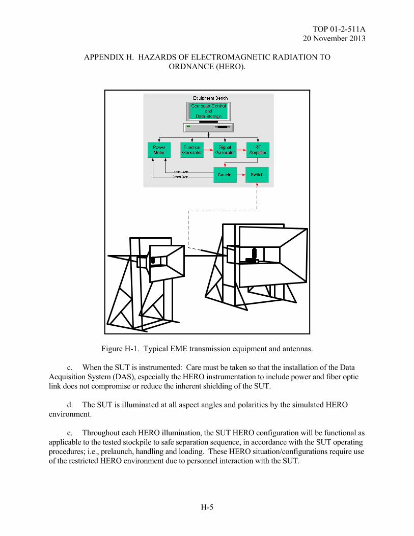
TOP 01-2-511A 20 November 2013
H-5
APPENDIX H. HAZARDS OF ELECTROMAGNETIC RADIATION TO ORDNANCE (HERO).
Figure H-1. Typical EME transmission equipment and antennas. c. When the SUT is instrumented: Care must be taken so that the installation of the Data Acquisition System (DAS), especially the HERO instrumentation to include power and fiber optic link does not compromise or reduce the inherent shielding of the SUT. d. The SUT is illuminated at all aspect angles and polarities by the simulated HERO environment. e. Throughout each HERO illumination, the SUT HERO configuration will be functional as applicable to the tested stockpile to safe separation sequence, in accordance with the SUT operating procedures; i.e., prelaunch, handling and loading. These HERO situation/configurations require use of the restricted HERO environment due to personnel interaction with the SUT.
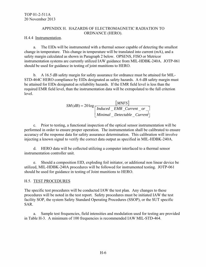
TOP 01-2-511A 20 November 2013
H-6
APPENDIX H. HAZARDS OF ELECTROMAGNETIC RADIATION TO ORDNANCE (HERO).
H.4.4 Instrumentation. a. The EIDs will be instrumented with a thermal sensor capable of detecting the smallest change in temperature. This change in temperature will be translated into current (mA), and a safety margin calculated as shown in Paragraph 2 below. OPSENS, FISO or Metricor instrumentation systems are currently utilized IAW guidance from MIL-HDBK-240A. JOTP-061 should be used for guidance in testing of joint munitions to HERO. b. A 16.5 dB safety margin for safety assurance for ordnance must be attained for MIL-STD-464C HERO compliance by EIDs designated as safety hazards. A 6 dB safety margin must be attained for EIDs designated as reliability hazards. If the EMR field level is less than the required EMR field level, than the instrumentation data will be extrapolated to the full criterion level.
CurrentDetectableMinimal
orCurrentEMRInducedMNFS
dBSM
__
____log20)(
c. Prior to testing, a functional inspection of the optical sensor instrumentation will be performed in order to ensure proper operation. The instrumentation shall be calibrated to ensure accuracy of the response data for safety assurance determination. This calibration will involve injecting a known signal to verify the correct data output as specified in MIL-HDBK-240A. d. HERO data will be collected utilizing a computer interfaced to a thermal sensor instrumentation controller unit. e. Should a composition EID, exploding foil initiator, or additional non linear device be utilized, MIL-HDBK-240A procedures will be followed for instrumented testing. JOTP-061 should be used for guidance in testing of Joint munitions to HERO. H.5. TEST PROCEDURES The specific test procedures will be conducted IAW the test plan. Any changes to these procedures will be noted in the test report. Safety procedures must be initiated IAW the test facility SOP, the system Safety Standard Operating Procedures (SSOP), or the SUT specific SAR. a. Sample test frequencies, field intensities and modulation used for testing are provided in Table H-3. A minimum of 100 frequencies is recommended IAW MIL-STD-464.
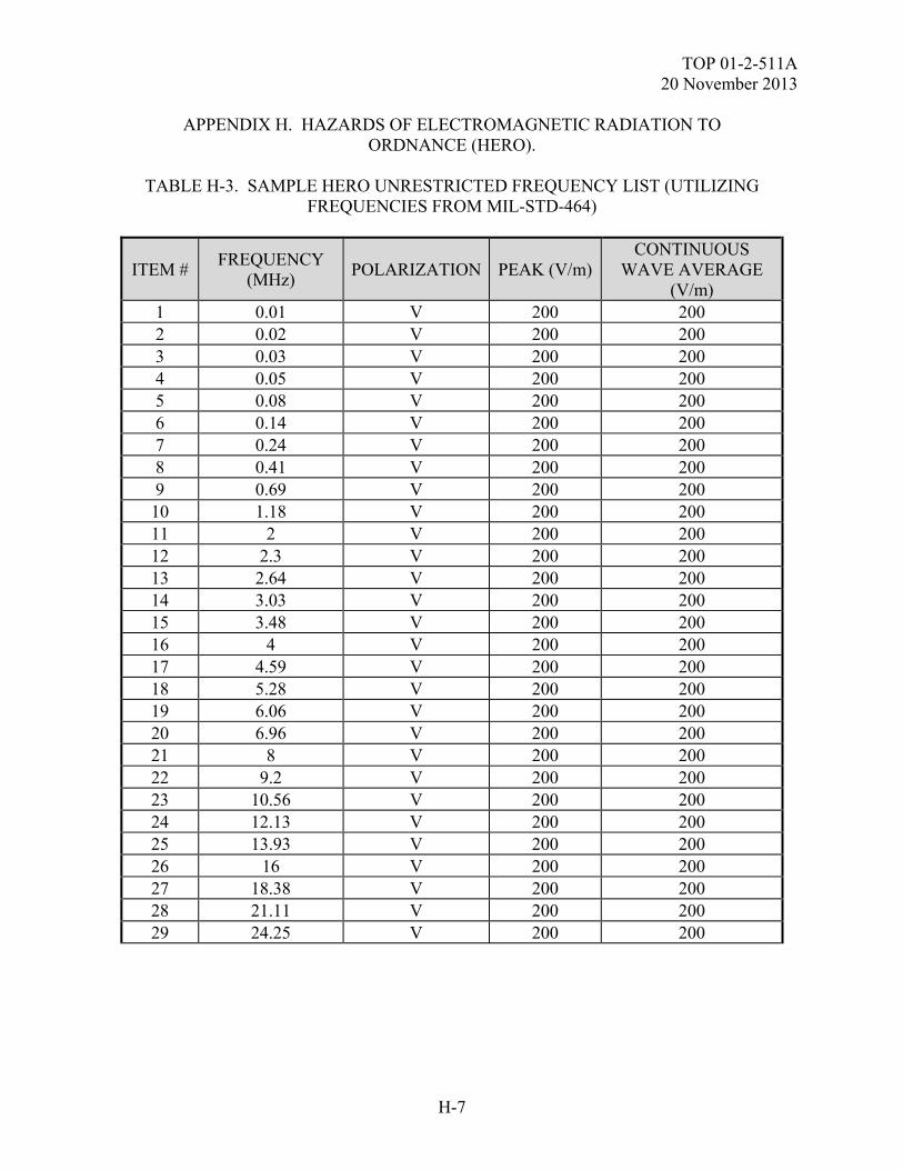
TOP 01-2-511A 20 November 2013
H-7
APPENDIX H. HAZARDS OF ELECTROMAGNETIC RADIATION TO ORDNANCE (HERO).
TABLE H-3. SAMPLE HERO UNRESTRICTED FREQUENCY LIST (UTILIZING
FREQUENCIES FROM MIL-STD-464)
ITEM # FREQUENCY
(MHz) POLARIZATION PEAK (V/m)
CONTINUOUS WAVE AVERAGE
(V/m) 1 0.01 V 200 200 2 0.02 V 200 200 3 0.03 V 200 200 4 0.05 V 200 200 5 0.08 V 200 200 6 0.14 V 200 200 7 0.24 V 200 200 8 0.41 V 200 200 9 0.69 V 200 200 10 1.18 V 200 200 11 2 V 200 200 12 2.3 V 200 200 13 2.64 V 200 200 14 3.03 V 200 200 15 3.48 V 200 200 16 4 V 200 200 17 4.59 V 200 200 18 5.28 V 200 200 19 6.06 V 200 200 20 6.96 V 200 200 21 8 V 200 200 22 9.2 V 200 200 23 10.56 V 200 200 24 12.13 V 200 200 25 13.93 V 200 200 26 16 V 200 200 27 18.38 V 200 200 28 21.11 V 200 200 29 24.25 V 200 200
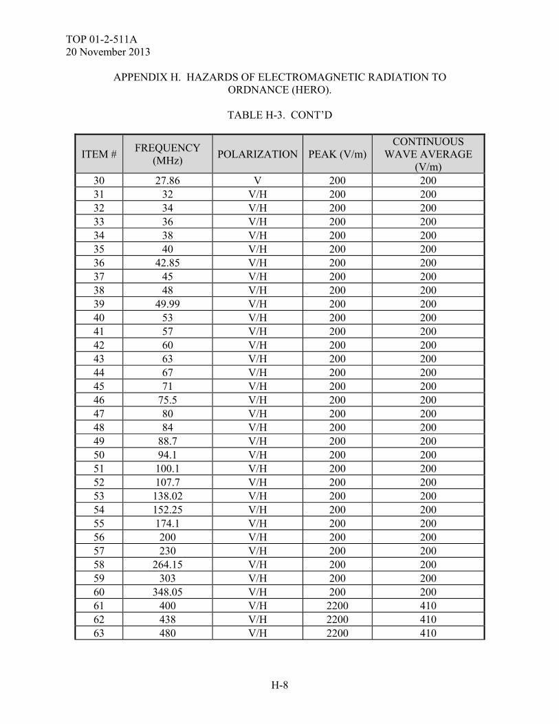
TOP 01-2-511A 20 November 2013
H-8
APPENDIX H. HAZARDS OF ELECTROMAGNETIC RADIATION TO ORDNANCE (HERO).
TABLE H-3. CONT’D
ITEM # FREQUENCY
(MHz) POLARIZATION PEAK (V/m)
CONTINUOUS WAVE AVERAGE
(V/m) 30 27.86 V 200 200 31 32 V/H 200 200 32 34 V/H 200 200 33 36 V/H 200 200 34 38 V/H 200 200 35 40 V/H 200 200 36 42.85 V/H 200 200 37 45 V/H 200 200 38 48 V/H 200 200 39 49.99 V/H 200 200 40 53 V/H 200 200 41 57 V/H 200 200 42 60 V/H 200 200 43 63 V/H 200 200 44 67 V/H 200 200 45 71 V/H 200 200 46 75.5 V/H 200 200 47 80 V/H 200 200 48 84 V/H 200 200 49 88.7 V/H 200 200 50 94.1 V/H 200 200 51 100.1 V/H 200 200 52 107.7 V/H 200 200 53 138.02 V/H 200 200 54 152.25 V/H 200 200 55 174.1 V/H 200 200 56 200 V/H 200 200 57 230 V/H 200 200 58 264.15 V/H 200 200 59 303 V/H 200 200 60 348.05 V/H 200 200 61 400 V/H 2200 410 62 438 V/H 2200 410 63 480 V/H 2200 410
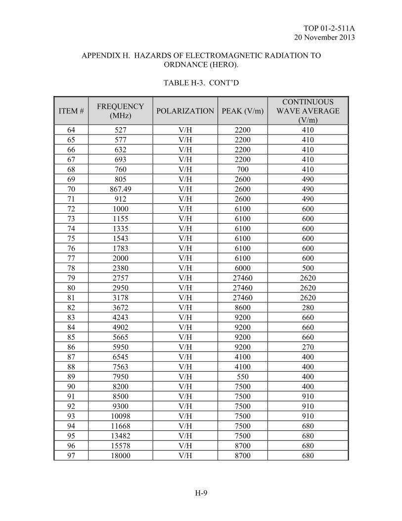
TOP 01-2-511A 20 November 2013
H-9
APPENDIX H. HAZARDS OF ELECTROMAGNETIC RADIATION TO ORDNANCE (HERO).
TABLE H-3. CONT’D
ITEM # FREQUENCY
(MHz) POLARIZATION PEAK (V/m)
CONTINUOUS WAVE AVERAGE
(V/m) 64 527 V/H 2200 410 65 577 V/H 2200 410 66 632 V/H 2200 410 67 693 V/H 2200 410 68 760 V/H 700 410 69 805 V/H 2600 490 70 867.49 V/H 2600 490 71 912 V/H 2600 490 72 1000 V/H 6100 600 73 1155 V/H 6100 600 74 1335 V/H 6100 600 75 1543 V/H 6100 600 76 1783 V/H 6100 600 77 2000 V/H 6100 600 78 2380 V/H 6000 500 79 2757 V/H 27460 2620 80 2950 V/H 27460 2620 81 3178 V/H 27460 2620 82 3672 V/H 8600 280 83 4243 V/H 9200 660 84 4902 V/H 9200 660 85 5665 V/H 9200 660 86 5950 V/H 9200 270 87 6545 V/H 4100 400 88 7563 V/H 4100 400 89 7950 V/H 550 400 90 8200 V/H 7500 400 91 8500 V/H 7500 910 92 9300 V/H 7500 910 93 10098 V/H 7500 910 94 11668 V/H 7500 680 95 13482 V/H 7500 680 96 15578 V/H 8700 680 97 18000 V/H 8700 680
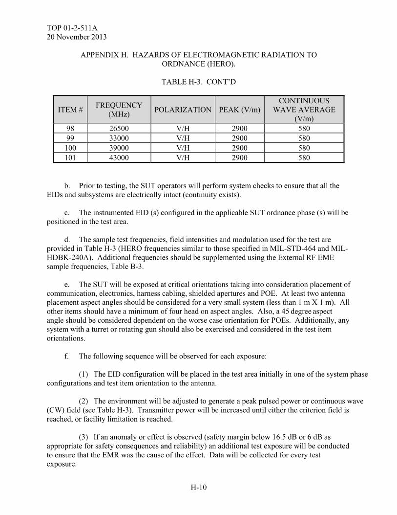
TOP 01-2-511A 20 November 2013
H-10
APPENDIX H. HAZARDS OF ELECTROMAGNETIC RADIATION TO ORDNANCE (HERO).
TABLE H-3. CONT’D
ITEM # FREQUENCY
(MHz) POLARIZATION PEAK (V/m)
CONTINUOUS WAVE AVERAGE
(V/m) 98 26500 V/H 2900 580 99 33000 V/H 2900 580 100 39000 V/H 2900 580 101 43000 V/H 2900 580
b. Prior to testing, the SUT operators will perform system checks to ensure that all the EIDs and subsystems are electrically intact (continuity exists). c. The instrumented EID (s) configured in the applicable SUT ordnance phase (s) will be positioned in the test area. d. The sample test frequencies, field intensities and modulation used for the test are provided in Table H-3 (HERO frequencies similar to those specified in MIL-STD-464 and MIL-HDBK-240A). Additional frequencies should be supplemented using the External RF EME sample frequencies, Table B-3. e. The SUT will be exposed at critical orientations taking into consideration placement of communication, electronics, harness cabling, shielded apertures and POE. At least two antenna placement aspect angles should be considered for a very small system (less than 1 m X 1 m). All other items should have a minimum of four head on aspect angles. Also, a 45 degree aspect angle should be considered dependent on the worse case orientation for POEs. Additionally, any system with a turret or rotating gun should also be exercised and considered in the test item orientations. f. The following sequence will be observed for each exposure: (1) The EID configuration will be placed in the test area initially in one of the system phase configurations and test item orientation to the antenna. (2) The environment will be adjusted to generate a peak pulsed power or continuous wave (CW) field (see Table H-3). Transmitter power will be increased until either the criterion field is reached, or facility limitation is reached. (3) If an anomaly or effect is observed (safety margin below 16.5 dB or 6 dB as appropriate for safety consequences and reliability) an additional test exposure will be conducted to ensure that the EMR was the cause of the effect. Data will be collected for every test exposure.
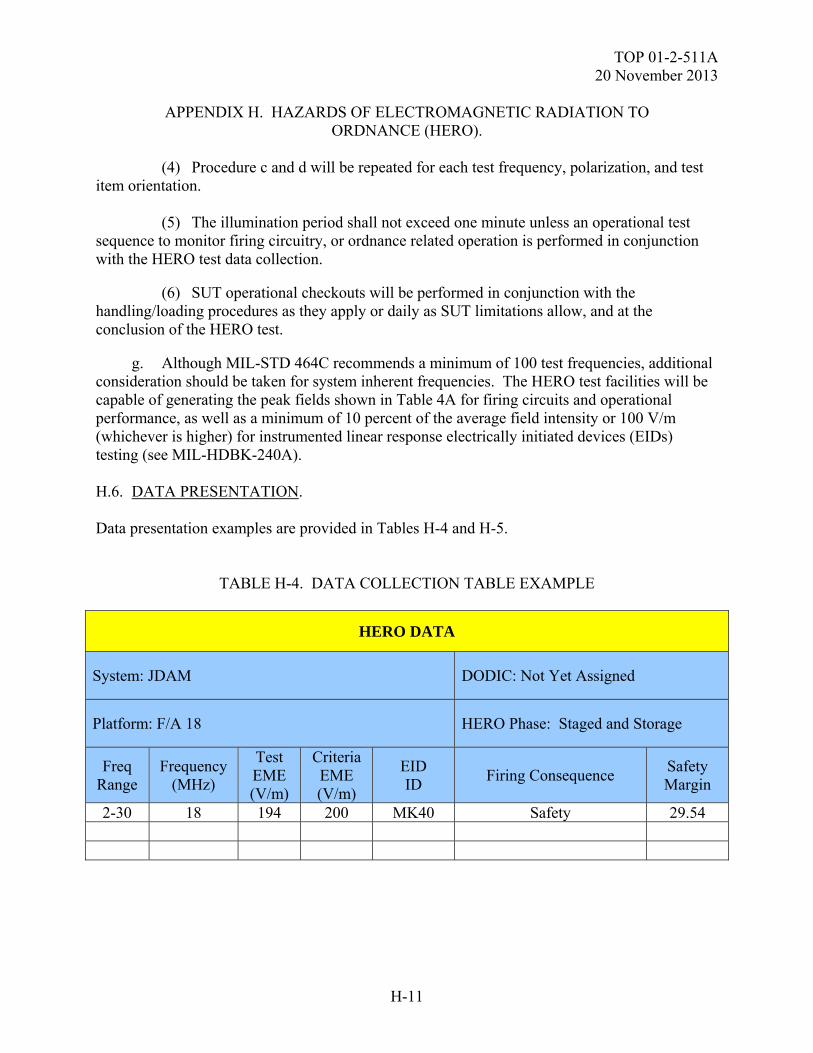
TOP 01-2-511A 20 November 2013
H-11
APPENDIX H. HAZARDS OF ELECTROMAGNETIC RADIATION TO ORDNANCE (HERO).
(4) Procedure c and d will be repeated for each test frequency, polarization, and test item orientation. (5) The illumination period shall not exceed one minute unless an operational test sequence to monitor firing circuitry, or ordnance related operation is performed in conjunction with the HERO test data collection. (6) SUT operational checkouts will be performed in conjunction with the handling/loading procedures as they apply or daily as SUT limitations allow, and at the conclusion of the HERO test. g. Although MIL-STD 464C recommends a minimum of 100 test frequencies, additional consideration should be taken for system inherent frequencies. The HERO test facilities will be capable of generating the peak fields shown in Table 4A for firing circuits and operational performance, as well as a minimum of 10 percent of the average field intensity or 100 V/m (whichever is higher) for instrumented linear response electrically initiated devices (EIDs) testing (see MIL-HDBK-240A). H.6. DATA PRESENTATION. Data presentation examples are provided in Tables H-4 and H-5.
TABLE H-4. DATA COLLECTION TABLE EXAMPLE
HERO DATA
System: JDAM DODIC: Not Yet Assigned
Platform: F/A 18 HERO Phase: Staged and Storage
Freq Range
Frequency (MHz)
Test EME (V/m)
Criteria EME (V/m)
EID ID
Firing Consequence Safety Margin
2-30 18 194 200 MK40 Safety 29.54
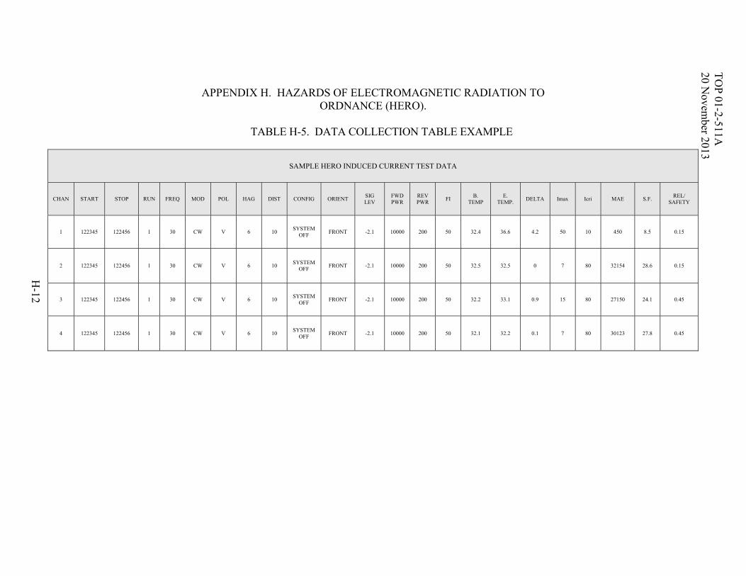
TO
P 01-2-511A
20 N
ovember 2013
H-12
APPENDIX H. HAZARDS OF ELECTROMAGNETIC RADIATION TO
ORDNANCE (HERO).
TABLE H-5. DATA COLLECTION TABLE EXAMPLE
SAMPLE HERO INDUCED CURRENT TEST DATA
CHAN START STOP RUN FREQ MOD POL HAG DIST CONFIG ORIENT SIG LEV
FWD PWR
REV PWR
FI B.
TEMP E.
TEMP. DELTA Imax Icri MAE S.F.
REL/ SAFETY
1 122345 122456 1 30 CW V 6 10 SYSTEM
OFF FRONT -2.1 10000 200 50 32.4 36.6 4.2 50 10 450 8.5 0.15
2 122345 122456 1 30 CW V 6 10 SYSTEM
OFF FRONT -2.1 10000 200 50 32.5 32.5 0 7 80 32154 28.6 0.15
3 122345 122456 1 30 CW V 6 10 SYSTEM
OFF FRONT -2.1 10000 200 50 32.2 33.1 0.9 15 80 27150 24.1 0.45
4 122345 122456 1 30 CW V 6 10 SYSTEM
OFF FRONT -2.1 10000 200 50 32.1 32.2 0.1 7 80 30123 27.8 0.45
TOP 01-2-511A 20 November 2013
H-13
APPENDIX H. HAZARDS OF ELECTROMAGNETIC RADIATION TO ORDNANCE (HERO).
H.7. DATA ANALYSIS PROCEDURE. a. Data from the External EME test environment measurements will be scored against the criteria levels set forth in MIL-STD 464, to determine the extent to which the test environment criteria and margins (if applicable), as well as equipment specification were met. Deficiencies will be identified and discussed with respect to criteria compliance and effects on the test results. b. The environment data will be compared and evaluated against the systems required criteria. c. Maximum No Fire Stimulus (MNFS). All EIDs will be tested using applicable military standards and statistical test methods to determine the MNFS levels. The test results will be shown along with the applicable margin or factor (safety assurance or reliability) and the MNFS requirement for the HERO test. (1) For EIDs where the MNFS is current (or voltage):
Safety Margin (dB) = 20 Log10 (MNFC/Iemr)
Where Iemr = the measured induced EMR current or the minimum detectable current
(MDC) of the instrumentation (or Vemr = the measured induced voltage or the minimum detectable voltage (MDV) of the instrumentation).
Where MNFC = the Minimum No Fire Current from the bare EID qualification test data
(2) For EIDs where MNFS is energy:
Safety Margin (dB) = 10 Log10 (MNFE/Eemr)
Where Eemr = the measured induced EMR energy or the minimum detectable energy (volts) of the instrumentation.
Where MNFE = the Minimum No Fire Energy from the bare EID qualification test data
TOP 01-2-511A 20 November 2013
H-14
APPENDIX H. HAZARDS OF ELECTROMAGNETIC RADIATION TO ORDNANCE (HERO).
Ideally the instrumentation MDC is small such that it can detect Iemr at any frequency and criteria. This HERO measurement is accomplished when the MDC is smaller than Iemr. In most cases, however, Iemr is too small to be observed. The safety margin calculation is then based on instrumentation MDC (IMD), not Iemr. Replacing a measurement of Iemr with MDC limits the validity of the safety margin calculation, but it errs on the conservative side by calculating a lower safety margin than is actually the case. The calculated safety margin would be compared to the required safety margin to determine if the EID is acceptable. The MDC of the FISO sensors is assumed to be 10 mA (IMD). The actual value will be measured before start of test. If the E-field available during the test is less than the criteria then the measured (EMR induced) current or energy will be extrapolated analytically to the required criteria and the data then calculated. This assumes a linear relationship between the applied E-field and the induced current. The extrapolated value for current or voltage is then used in place of the measured induced EMR current value to calculate the safety margin. The extrapolated level is defined as follows:
Iext = Iemr (Ecrit/Etest) Where Iext = the extrapolated value of the induced EMR current (A),
Iemr = the measured value for the induced EMR current (or MDC) (A), Ecrit = the required (criteria) E-field intensity (V/m), and
Etest = the E-field intensity available during the test (V/m) If the E-field available during the test is less than the criteria, then the FISO sensor MDC limits the maximum allowable E-field extrapolation. The maximum allowable extrapolation factor is calculated per the HERO Test Guide:
Fmax = Icrit/IMD
Where Icrit = the EID critical current to meet the required margin (A), IMD = the FISO MDC (A)
Icrit (or Vcrit) is calculated with the following equation: Icrit (or Vcrit) = MNFS/10(SM/20) for current (or voltage) measurements, or Ecrit = MNFS/10(SM/10) for energy measurements Where SM is the Safety Margin (16.5 dB for safety or 6 dB for reliability) To meet test requirements, each test field must equal or exceed the ratio of the Criteria Test Field and the Maximum Allowable Extrapolation Factor (Fmax).
TOP 01-2-511A 20 November 2013
H-15
APPENDIX H. HAZARDS OF ELECTROMAGNETIC RADIATION TO ORDNANCE (HERO).
d. The test data will be compared to the applicable criteria set forth in the SUT specification, and SUT test plan and the pre-event baseline measurements to determine the extent to which the test criteria are met and the effects of the HERO test environment on the SUT. Test anomalies will be assessed to determine if they should be classified as SUT failures and if so, further assessed with regards to causes, test parameters at which they occurred, mission impact and safety.

TOP 01-2-511A 20 November 2013
H-16
(This page is intentionally blank.)
TOP 01-2-511A 20 November 2013
I-1
APPENDIX I. TEMPEST. I.1. APPLICABILITY. The objective of this subtest is to determine if National Security Information (NSI) has the potential of being compromised by unintentional emanations from information processing equipment. Areas that fall under the TEMPEST umbrella are TEMPEST, and NONSTOP. I.2. REQUIREMENTS. a. MIL-STD-464C, Paragraph 5.12, TEMPEST: “National security information shall not be compromised by emanations from classified information processing equipment. Compliance shall be verified by test, analysis, inspections or a combination thereof. (National Security Telecommunications and Information Systems Security Advisory Memorandum (NSTISSAM) TEMPEST/1-9219 and Committee on National Security Systems (CNNS) Advisory Memorandum TEMPEST 01-0220 provide testing methodology for verifying compliance with TEMPEST requirements.)” b. Compromising emanations are unintentional intelligence bearing signals, which if intercepted and analyzed, would disclose national security information transmitted, received, handled, or otherwise processed by any classified information processing system. The requirement for TEMPEST is found in Department of Defense Directive (DODD) 5200.1921 (classified). For Air Force aircraft, this requirement is generally applied to the communications subsystem only. c. Baseline requirements are contained in NSTISSAM TEMPEST/1-92, NSTISSAM TEMPEST/1-9322, NSTISSAM TEMPEST/2-9523, CNNS Advisory Memorandum TEMPEST 01-02, and Navy publication IA PUB-5239-3124. c. The need to apply TEMPEST requirements is determined by the Certified TEMPEST Technical Authority (CTTA). The CTTA considers several vulnerability and threat factors to determine the residual risk to which the information is exposed. The CTTA then determines if countermeasures are required to reduce risk to an acceptable level and identifies the most cost effective approach to achieving imposed TEMPEST requirements. d. Points of contact for the military services are as follows: Air Force: HQ AFCA/TCBA-CTTA, 203 West Losey St, Room 2100, Scott AFB, IL 62225-5222. Telephone: (618) 256-5588. By e-mail: [email protected]. Army: Army TEMPEST Program Manager, 310th Military Intelligence Battalion, IAMG-C-TMP, 4552 Pike Road, Fort George G. Meade, MD 20755. Telephone: (301) 677-4440. By email: [email protected]. (Navy TEMPEST is covered under Information Assurance).
TOP 01-2-511A 20 November 2013
I-2
APPENDIX I. TEMPEST.
Navy: Inquiry’s on the Navy TEMPEST Policy may be directed to: https://infosec.navy.mil. e. Emanations Analysis: NSTISSAM TEMPEST/2-9125 Compromising Emanations Analysis Handbook Equipment/System Testing NSTISSAM TEMPEST/1-92 Compromising Emanations Laboratory Test Requirements,
Electromagnetics NSTISSAM TEMPEST/1-93 Compromising Emanations Field Test Requirements,
Electromagnetics CNSSAM TEMPEST 01-02 NONSTOP Evaluation Standard NSTISSAM TEMPEST/2-0026 Rationale NONSTOP Evaluation Techniques KAG-30 ()/TSEC27 Compromising Emanations Standard for Cryptographic
Equipment NSTISSAM TEMPEST/2-9328 Rationale for Compromising Emanations Laboratory and Field
Test Requirements, Electromagnetics I.3. TEST PROCEDURE. The first step in the testing process should be that the Program Manager of the SUT should contact the CTTA very early on in the project and start a dialog to determine what TEMPEST requirements should be in the specifications and what TEMPEST testing will have to be done. Information that the CTTA will require at some point will be the following: a. A discussion of the system to include. (1) System description. (2) A functional system description how specific circuits are handling information. (3) How the system is fielded, i.e. setup, lay out, tent equipment, SWLANS, external cabling, etc. (4) How the system is to be deployed and integrated into the system of systems, i.e., standalone (autonomous), in a TOC or in a shelter.
TOP 01-2-511A 20 November 2013
I-3
APPENDIX I. TEMPEST. (5) Detailed block diagram of all signals and ID's of RED (classified) signals. This should include any keyboards, monitors, printers that process classified. Where fiber optics to Brigade commanders position, to NTDR then to adjacent brigade TOC, map information to server, etc. (6) Size of Control Space (How big will the perimeter around the vehicle be that is controlled?). (7) Type of power (How is the system going to be powered worst case, external power, from generator or shore power, on board generator or alternator, type of power i.e., 50/60/400 Hz, 240 single phase, 100 Amp that uses 3 conductors with ground, 4 “O” cable). b. Type of transmission media exiting the system to include. (1) Type of radios, SINCGARS, EPLRS, HF, GBS, JTRS, NTDR, SPITFIRE, SOTM, Blue Force Tracking, etc. (2) Wireless LAN (Secure or unsecure). (3) Fiber optics. (4) Twisted pair (26/50/100 pair hocks). (5) Coax. (6) Coax 10 base-T. (7) CATV. c. Type of communications within system to include. (1) Voice, i.e. VIC-3, TOCNET, etc. (2) Video. (3) Data - Type of data transfer (serial or parallel). (a) Rate the data is transferred on each data path (time or frequency). (b) Data path carries classified data or not.
(c) Data path carries classified, percent of total data across this path that is classified.
(d) Highest classification of the data.
TOP 01-2-511A 20 November 2013
I-4
APPENDIX I. TEMPEST. (4) Data flow diagrams of all communication types and logic to determine those routings. (5) Any external communications or data transfer capability using land wires (type and distance). d. Computer systems (all computers and peripherals addressed and classified computers and peripherals identified as such). (1) Monitors – refresh rates, scan rates, interleaved/non-interleaved. (2) Keyboards – polling rate. (3) CPU – clock rates, data rate on the internal bus, single/dual processor. (4) Routers/HUBs/Switches/firewalls that process information. (5) Printers. (6) Plotters. (7) Overhead projectors (ones tied to a computer). (8) External storage. e. The better the information the more accurate the cost estimate and test plan. Any further discussion beyond what is discussed above would require a higher classification of this document. Once the CTTA has determined what testing is required US Army Electronic Proving Ground should be contacted to develop the RED signals matrix and testing performed. I.4. DATA ANALYSIS PROCEDURE. The test data will be compared to the applicable criteria set forth in the SUT specification, and SUT test plan and the pre-event baseline measurements to determine the extent to which the test criteria are met and the effects of the TEMPEST test environment on the SUT. Test anomalies will be assessed to determine if they should be classified as SUT failures and if so, further assessed with regards to causes, test parameters at which they occurred, mission impact, and safety.
TOP 01-2-511A 20 November 2013
J-1
APPENDIX J. HIGH POWER MICROWAVE (HPM). J.1. APPLICABILITY.
a. This test method is applicable to equipment at the system level IAW the equipment specification. To provide the methods to assess the survivability of the system to the effects produced by a HPM environment.
b. To determine whether the subsystem or system’s operational performance
requirements are met when subjected to the specified red and/or blue HPM threat levels. c. This Appendix is meant to act as a guide and is not a replacement for a test plan.
Compliance shall be verified by system-level test, analysis, or a combination thereof. Omission The extracted levels are omitted from this document to maintain an unclassified
status. J.2. REQUIREMENTS.
a. To assess the operational survivability and identify susceptibilities to the system when exposed to the HPM environment, as specified in Radio Frequency Directed Energy Weapon Threat Exposure Levels for Selected US Army Tactical Systems, ARL-TR-492, System Specifications, and MIL-STD-464C. This applies to test and verification of both narrowband and wideband HPM testing environments. HPM testing is applicable for airborne, sea, space and ground system testing of a complete system and platform, both new and modified, and can be adapted to suit subsystem and piece part testing requirements.
b. The system shall remain combat effective without component replacement. c. The system must operate and meet mission requirements after introduction of the
HPM environment.
J.3. PURPOSE. The purpose of this test procedure is to verify the ability of the SUT to survive an HPM environment IAW the specification performance requirements.
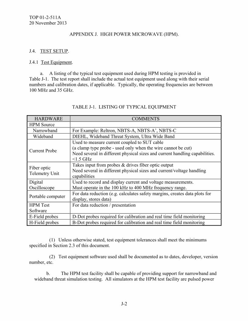
TOP 01-2-511A 20 November 2013
J-2
APPENDIX J. HIGH POWER MICROWAVE (HPM).
J.4. TEST SETUP. J.4.1 Test Equipment. a. A listing of the typical test equipment used during HPM testing is provided in Table J-1. The test report shall include the actual test equipment used along with their serial numbers and calibration dates, if applicable. Typically, the operating frequencies are between 100 MHz and 35 GHz.
TABLE J-1. LISTING OF TYPICAL EQUIPMENT
HARDWARE COMMENTS HPM Source Narrowband For Example: Reltron, NBTS-A, NBTS-A’, NBTS-C Wideband DIEHL, Wideband Threat System, Ultra Wide Band
Current Probe
Used to measure current coupled to SUT cable (a clamp type probe - used only when the wire cannot be cut) Need several in different physical sizes and current handling capabilities. <1.5 GHz
Fiber optic Telemetry Unit
Takes input from probes & drives fiber optic output Need several in different physical sizes and current/voltage handling capabilities
Digital Oscilloscope
Used to record and display current and voltage measurements. Must operate in the 100 kHz to 400 MHz frequency range.
Portable computer For data reduction (e.g. calculates safety margins, creates data plots for display, stores data)
HPM Test Software
For data reduction / presentation
E-Field probes D-Dot probes required for calibration and real time field monitoring H-Field probes B-Dot probes required for calibration and real time field monitoring (1) Unless otherwise stated, test equipment tolerances shall meet the minimums specified in Section 2.3 of this document. (2) Test equipment software used shall be documented as to dates, developer, version number, etc.
b. The HPM test facility shall be capable of providing support for narrowband and wideband threat simulation testing. All simulators at the HPM test facility are pulsed power
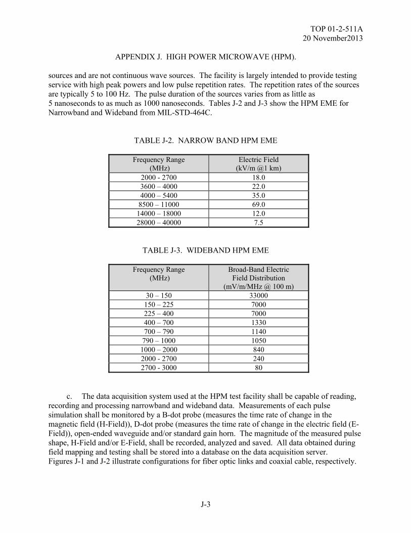
TOP 01-2-511A 20 November2013
J-3
APPENDIX J. HIGH POWER MICROWAVE (HPM). sources and are not continuous wave sources. The facility is largely intended to provide testing service with high peak powers and low pulse repetition rates. The repetition rates of the sources are typically 5 to 100 Hz. The pulse duration of the sources varies from as little as 5 nanoseconds to as much as 1000 nanoseconds. Tables J-2 and J-3 show the HPM EME for Narrowband and Wideband from MIL-STD-464C.
TABLE J-2. NARROW BAND HPM EME
Frequency Range (MHz)
Electric Field (kV/m @1 km)
2000 - 2700 18.0 3600 – 4000 22.0 4000 – 5400 35.0
8500 – 11000 69.0 14000 – 18000 12.0 28000 – 40000 7.5
TABLE J-3. WIDEBAND HPM EME
Frequency Range (MHz)
Broad-Band Electric Field Distribution
(mV/m/MHz @ 100 m) 30 – 150 33000 150 – 225 7000 225 – 400 7000 400 – 700 1330 700 – 790 1140
790 – 1000 1050 1000 – 2000 840 2000 - 2700 240 2700 - 3000 80
c. The data acquisition system used at the HPM test facility shall be capable of reading, recording and processing narrowband and wideband data. Measurements of each pulse simulation shall be monitored by a B-dot probe (measures the time rate of change in the magnetic field (H-Field)), D-dot probe (measures the time rate of change in the electric field (E-Field)), open-ended waveguide and/or standard gain horn. The magnitude of the measured pulse shape, H-Field and/or E-Field, shall be recorded, analyzed and saved. All data obtained during field mapping and testing shall be stored into a database on the data acquisition server. Figures J-1 and J-2 illustrate configurations for fiber optic links and coaxial cable, respectively.
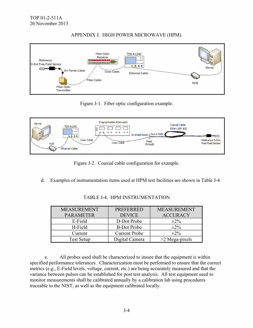
TOP 01-2-511A 20 November 2013
J-4
APPENDIX J. HIGH POWER MICROWAVE (HPM).
Figure J-1. Fiber optic configuration example.
Figure J-2. Coaxial cable configuration for example.
d. Examples of instrumentation items used at HPM test facilities are shown in Table J-4
TABLE J-4. HPM INSTRUMENTATION
MEASUREMENT PARAMETER
PREFERRED DEVICE
MEASUREMENT ACCURACY
E-Field D-Dot Probe ±2% H-Field B-Dot Probe ±2% Current Current Probe ±2%
Test Setup Digital Camera >2 Mega-pixels e. All probes used shall be characterized to insure that the equipment is within specified performance tolerances. Characterization must be performed to ensure that the correct metrics (e.g., E-Field levels, voltage, current, etc.) are being accurately measured and that the variance between pulses can be established for post test analysis. All test equipment used to monitor measurements shall be calibrated annually by a calibration lab using procedures traceable to the NIST, as well as the equipment calibrated locally.
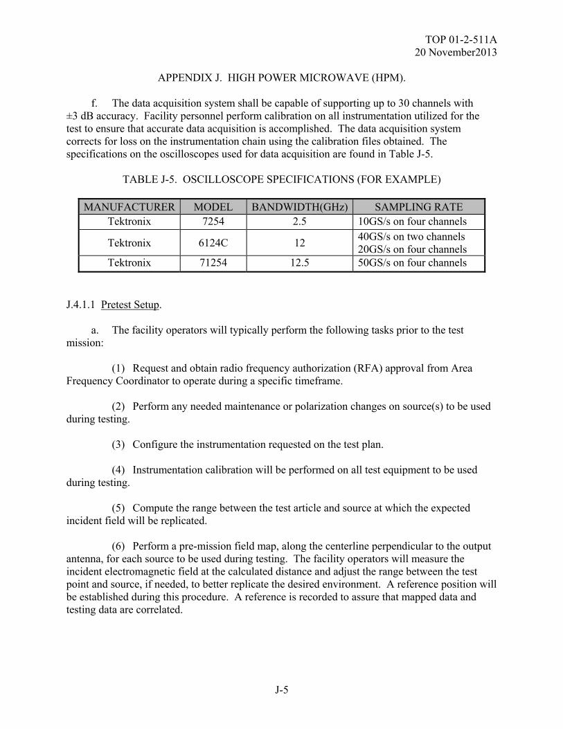
TOP 01-2-511A 20 November2013
J-5
APPENDIX J. HIGH POWER MICROWAVE (HPM). f. The data acquisition system shall be capable of supporting up to 30 channels with ±3 dB accuracy. Facility personnel perform calibration on all instrumentation utilized for the test to ensure that accurate data acquisition is accomplished. The data acquisition system corrects for loss on the instrumentation chain using the calibration files obtained. The specifications on the oscilloscopes used for data acquisition are found in Table J-5.
TABLE J-5. OSCILLOSCOPE SPECIFICATIONS (FOR EXAMPLE)
MANUFACTURER MODEL BANDWIDTH(GHz) SAMPLING RATE Tektronix 7254 2.5 10GS/s on four channels
Tektronix 6124C 12 40GS/s on two channels 20GS/s on four channels
Tektronix 71254 12.5 50GS/s on four channels
J.4.1.1 Pretest Setup. a. The facility operators will typically perform the following tasks prior to the test mission: (1) Request and obtain radio frequency authorization (RFA) approval from Area Frequency Coordinator to operate during a specific timeframe. (2) Perform any needed maintenance or polarization changes on source(s) to be used during testing. (3) Configure the instrumentation requested on the test plan. (4) Instrumentation calibration will be performed on all test equipment to be used during testing. (5) Compute the range between the test article and source at which the expected incident field will be replicated. (6) Perform a pre-mission field map, along the centerline perpendicular to the output antenna, for each source to be used during testing. The facility operators will measure the incident electromagnetic field at the calculated distance and adjust the range between the test point and source, if needed, to better replicate the desired environment. A reference position will be established during this procedure. A reference is recorded to assure that mapped data and testing data are correlated.

TOP 01-2-511A 20 November 2013
J-6
APPENDIX J. HIGH POWER MICROWAVE (HPM). (7) Verify instrumentation hardware is working properly and make any necessary changes. (8) Any software development, fabrication and purchases needed to perform and/or support testing may be completed months in advance as required. b. Due to ionizing and non-ionizing radiation produced by sources at the HPM facility all personnel present during testing must comply with the instructions given to them by the facility operators. All visitors will be informed of approved and restricted areas upon arrival at the facility. Any special requests, instructions or test plan changes must be communicated to the facility operators as soon as possible in order to accommodate. c. Engineering judgment becomes critical when schedule impacts occur such as facility downtime, inclement weather, failures and/or re-prioritization. Under such conditions, the test officer must determine the problem, deviate from the original test plan and devise an alternate plan or set of procedures in order to complete the mission. J.5. TEST PROCEDURES. J.5.1 Test Execution. J.5.1.1 Pretest Analysis.
a. Thoroughly examine the test article and verify it is not damaged and is operating properly. The test article must be fully operational before exposure to the HPM environment.
b. Note test article orientation, configuration and position. c. Note and determine if instrumentation setup is acceptable and meets requirements. d. Note and determine if test location and field intensities are acceptable and meets
requirements. e. Note and determine if test article setup is appropriate and meets requirements.
The facility operators and Test Officer or Test Engineer will make the necessary changes to the set up if any system or facility configurations are not acceptable. J.5.1.2 Test Organization. All visitors to the facility must be accounted for and must obey and abide by any safety protocol and mechanisms in place at the HPM test facility. The test officer will make arrangements with Health Physics to get all visitors issued dosimetry and obtain radiation briefing. All personnel
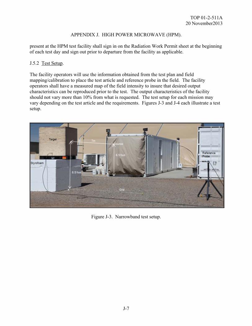
TOP 01-2-511A 20 November2013
J-7
APPENDIX J. HIGH POWER MICROWAVE (HPM). present at the HPM test facility shall sign in on the Radiation Work Permit sheet at the beginning of each test day and sign out prior to departure from the facility as applicable. J.5.2 Test Setup. The facility operators will use the information obtained from the test plan and field mapping/calibration to place the test article and reference probe in the field. The facility operators shall have a measured map of the field intensity to insure that desired output characteristics can be reproduced prior to the test. The output characteristics of the facility should not vary more than 10% from what is requested. The test setup for each mission may vary depending on the test article and the requirements. Figures J-3 and J-4 each illustrate a test setup.
Figure J-3. Narrowband test setup.
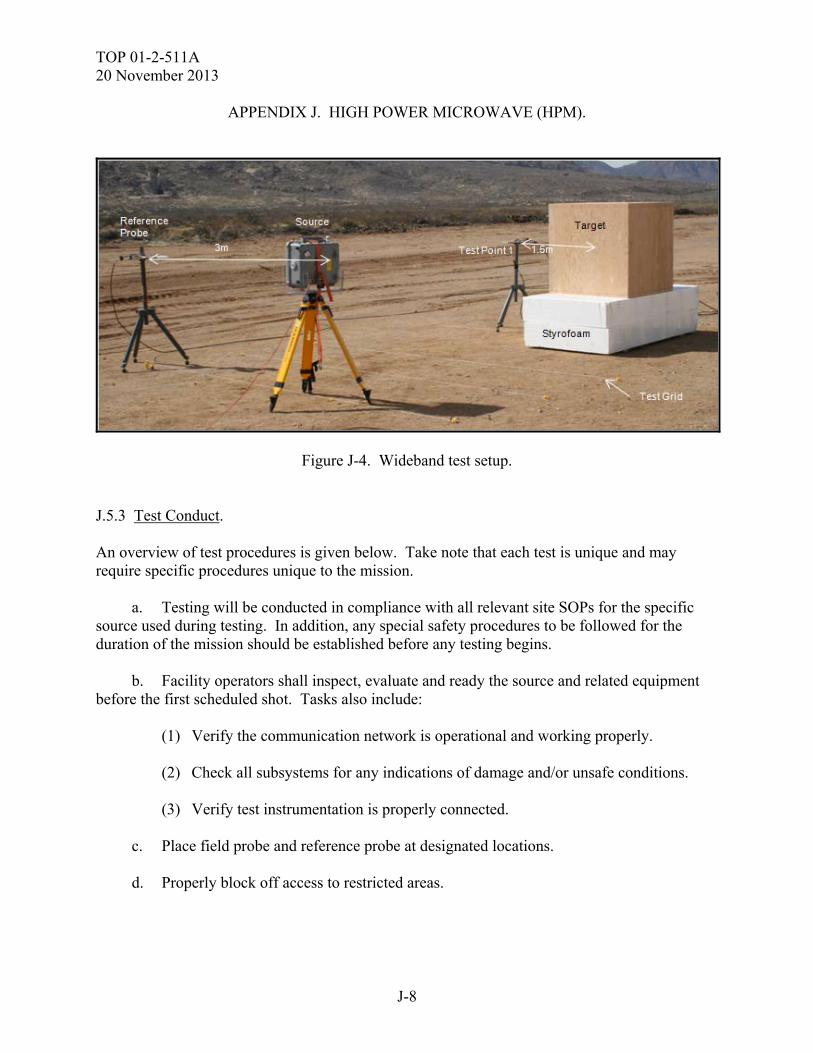
TOP 01-2-511A 20 November 2013
J-8
APPENDIX J. HIGH POWER MICROWAVE (HPM).
Figure J-4. Wideband test setup. J.5.3 Test Conduct. An overview of test procedures is given below. Take note that each test is unique and may require specific procedures unique to the mission.
a. Testing will be conducted in compliance with all relevant site SOPs for the specific source used during testing. In addition, any special safety procedures to be followed for the duration of the mission should be established before any testing begins.
b. Facility operators shall inspect, evaluate and ready the source and related equipment
before the first scheduled shot. Tasks also include:
(1) Verify the communication network is operational and working properly. (2) Check all subsystems for any indications of damage and/or unsafe conditions. (3) Verify test instrumentation is properly connected.
c. Place field probe and reference probe at designated locations. d. Properly block off access to restricted areas.
TOP 01-2-511A 20 November2013
J-9
APPENDIX J. HIGH POWER MICROWAVE (HPM). e. Perform head count to ensure that all personnel are accounted for and verify area is
clear, using safety cameras or by performing a walk through prior to engaging the siren and the RED flashing lights.
f. Source operator will receive a “go-ahead” from TO, safety personnel and data
acquisition operator before the simulator is armed and fired. After every shot has been fired the operator will SAFE the system and record all required transmitter data in the source Operations Log book.
g. Complete a field map for every source at every level using a test probe before placing
the test article in the field. The test article will be placed in the field once the field calibration has been completed.
h. Expose test article to the characterized environment. The performance of the source
will be monitored by instrumentation in the reference position and by the internal source diagnostics, if applicable. Test setup shall be photographed for each test orientation and configuration, if applicable.
i. The data acquisition personnel will review information obtained, save, process and
make any necessary configuration changes. j. The test officer will assess the impact of the HPM environment on the test article. k. Repeatedly expose and assess the test article for each specified environment,
orientation and polarization. The environment will be adjusted to generate the intended field intensity and the test article will be positioned at the proper location for exposure. This procedure will be repeated until the amount of requested data is obtained for all functional modes and system configurations.
l. If an anomaly or effect is observed; testing shall not continue until the problem is
understood and its effects on the test article are assessed. In the event of an upset, the effected system(s) or sub-system(s) will be identified and power cycled in an attempt to re-establish normal operation and record the recovery time. Testing must be repeated at the same level and orientation to determine whether the upset is attributable to the current HPM environment. J.6. DATA REQUIRED. The following resources will be supplied to the test officer:
a. A document containing test article configuration, frequency levels, source identification, source configuration and data measurements acquired.
b. Complete set of pretest mapping data.
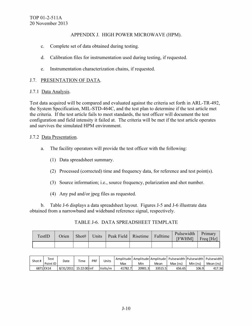
TOP 01-2-511A 20 November 2013
J-10
APPENDIX J. HIGH POWER MICROWAVE (HPM). c. Complete set of data obtained during testing. d. Calibration files for instrumentation used during testing, if requested. e. Instrumentation characterization chains, if requested.
J.7. PRESENTATION OF DATA. J.7.1 Data Analysis. Test data acquired will be compared and evaluated against the criteria set forth in ARL-TR-492, the System Specification, MIL-STD-464C, and the test plan to determine if the test article met the criteria. If the test article fails to meet standards, the test officer will document the test configuration and field intensity it failed at. The criteria will be met if the test article operates and survives the simulated HPM environment. J.7.2 Data Presentation. a. The facility operators will provide the test officer with the following: (1) Data spreadsheet summary. (2) Processed (corrected) time and frequency data, for reference and test point(s). (3) Source information; i.e., source frequency, polarization and shot number. (4) Any psd and/or jpeg files as requested. b. Table J-6 displays a data spreadsheet layout. Figures J-5 and J-6 illustrate data obtained from a narrowband and wideband reference signal, respectively.
TABLE J-6. DATA SPREADSHEET TEMPLATE
TestID Orien Shot# Units Peak Field Risetime Falltime Pulsewidth [FWHM]
Primary Freq [Hz]
Shot # Test
Point ID Date Time PRF Units
Amplitude
Max
Amplitude
Min
Amplitude
Mean
Pulsewidth
Max (ns)
Pulsewidth
Min (ns)
Pulsewidth
Mean (ns)
6871 EX14 8/31/2011 15:22:00 inf Volts/m 41782.7 20901.3 33515.5 656.65 106.9 417.34
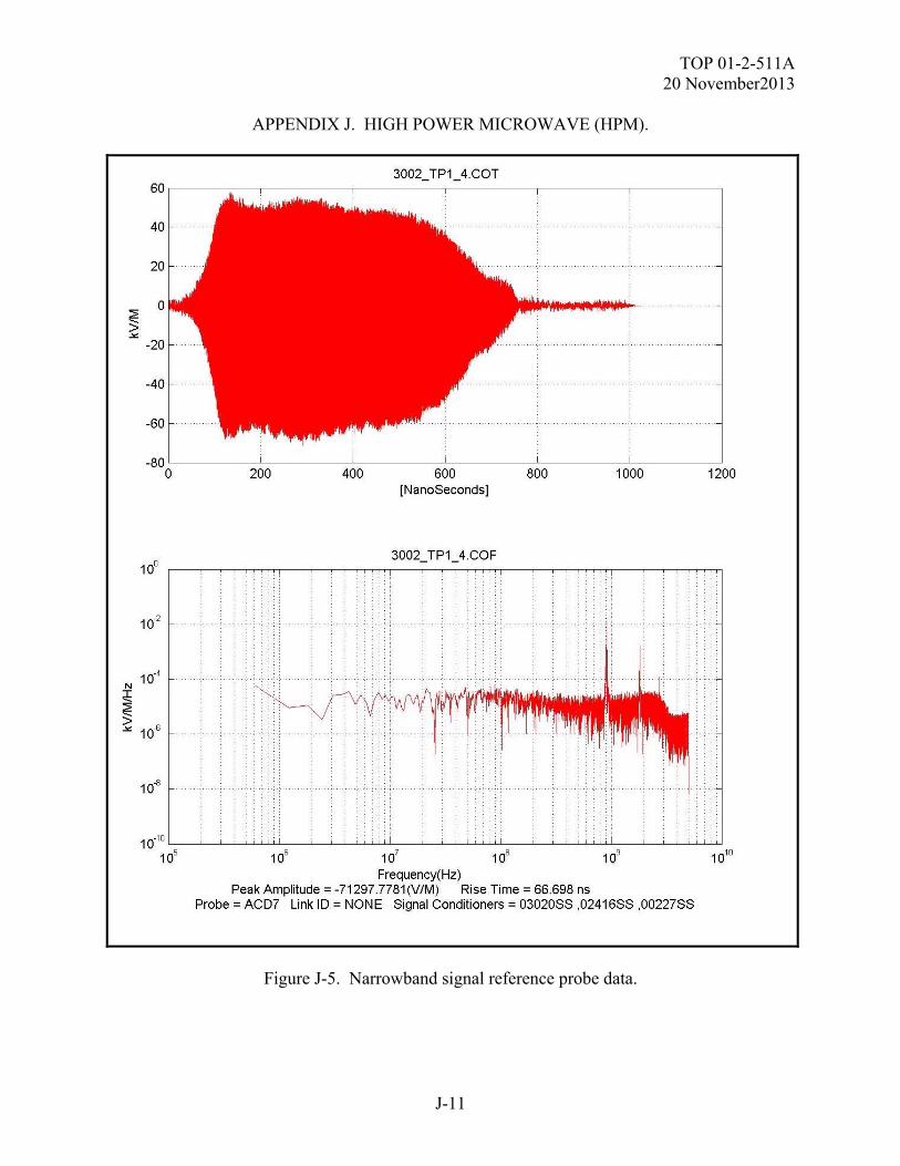
TOP 01-2-511A 20 November2013
J-11
APPENDIX J. HIGH POWER MICROWAVE (HPM).
Figure J-5. Narrowband signal reference probe data.
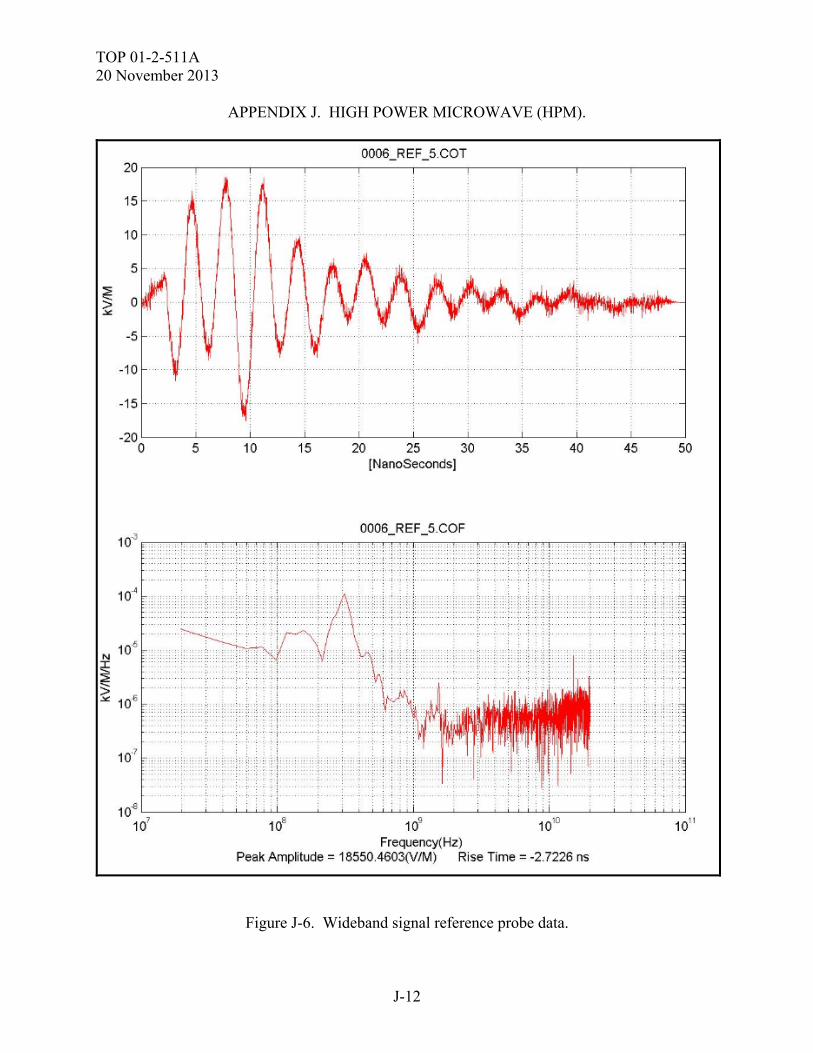
TOP 01-2-511A 20 November 2013
J-12
APPENDIX J. HIGH POWER MICROWAVE (HPM).
Figure J-6. Wideband signal reference probe data.
TOP 01-2-511A 20 November 2013
K-1
APPENDIX K. INTRA SYSTEM ELECTROMAGNETIC COMPATIBILITY, SYSTEM EMISSIONS, ELECTRIC FIELD, 10 kHz to 40 GHz.
K.1. APPLICABILITY. This requirement applies to all radiated emissions from equipment and subsystem enclosures, interconnecting cables, and antennas designed to be permanently mounted to the SUT (receivers and transmitters in standby mode). This requirement does not apply at the transmitter fundamental frequencies. The requirement is applicable from 10.0 kHz to 40.0 GHz (depending on the procuring agency). At a minimum, testing is required either up to 1.0 GHz or at ten times the highest intentionally generated frequency within the SUT, whichever is greater. It should be noted that there are differences between some of the MIL-STD-461E29 and MIL-STD-461F test set up and those specific procedure should be followed for each. This test procedure addresses those of MIL-STD-461E, but will show sample set ups for MIL-STD-461F as well. NOTE: Those SUT program offices requirements that reference other than the military standard requirements will have their data collected in accordance with that documents procedures, and the requirements specified within. K.2. PURPOSE. This test procedure is used to verify that the radiated electric field emissions from the SUT and associated cabling do not exceed specified requirements. K.3. TEST SETUP. K.3.1 Test Equipment. The test equipment shall be as follows: a. Measurement Receivers for example; (1) Electrometrics EMC-30. (2) Electrometrics EMC-60. (3) Rohde & Schwarz ESIB-40 or a spectrum analyzer that meets the characteristics specified in MIL-STD-461E, paragraphs 40.3.10.2 through 40.3.10.4. b. Data Recording Device. Any computer with appropriate RE software, Tile Version 3.4.k.4, ESK1 Version 1.71, or EMC32 Version 5.10.99 to drive the receivers and to record the data. c. Antennas, for example
TOP 01-2-511A 20 November 2013
K-2
APPENDIX K. INTRA SYSTEM ELECTROMAGNETIC COMPATIBILITY, SYSTEM EMISSIONS, ELECTRIC FIELD, 10 kHz to 40 GHz.
(1) 10.0 kHz to 30.0 MHz, 104 cm rod with impedance matching network, Electrometrics RVA-30 or similar. (a) Since the impedance matching network includes a preamplifier (active rod), observe the overload precautions. (b) Use a square counterpoise measuring at least 60 cm on a side. (2) 30.0 MHz to 200.0 MHz, Biconical, 137 cm tip to tip, Electrometrics BIA-30, EMCO 3104C or similar. (3) 200.0 MHz to 1.0 GHz, double ridge horn, 69.0 by 94.5 cm opening, Electrometrics RGA-30 or similar. (4) 1.0 GHz to 18.0 GHz, double ridge horn, 24.2 by 13.6 cm opening, Electrometrics RGA-50, Electrometrics RGA-60, Electrometrics RGA-180 or similar. (5) 18.0 GHz to 26.5 GHz, Waveguide Horn, 1.51 by 1.16 in. opening, Loral Narda or similar. (6) 26.5 GHz to 40.0 GHz, Waveguide Horn, 1.06 by 0.82 in. opening, Loral Narda or similar. d. Signal Generators for example: (1) Hewlett Packard 83640B, 83623A. (2) Fluke 6080A. (3) Rohde & Schwarz SML-01. (4) Anritsu 68369A/NV. e. Stub Radiator. f. Capacitor, 10 microfarad, Solar Electronics 6512-106R, 7113-106R, or similar. g. LISNs, Solar Electronics 9233-50-TS-50-N, 8116-50-TS-100-N, or similar. K.3.2 Setup. The test setup is as follows:
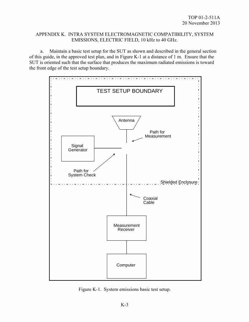
TOP 01-2-511A 20 November 2013
K-3
APPENDIX K. INTRA SYSTEM ELECTROMAGNETIC COMPATIBILITY, SYSTEM EMISSIONS, ELECTRIC FIELD, 10 kHz to 40 GHz.
a. Maintain a basic test setup for the SUT as shown and described in the general section of this guide, in the approved test plan, and in Figure K-1 at a distance of 1 m. Ensure that the SUT is oriented such that the surface that produces the maximum radiated emissions is toward the front edge of the test setup boundary.
Signal Generator
Path for System Check
TEST SETUP BOUNDARY
Path forMeasurement
MeasurementReceiver
Computer
Shielded Enclosure
Antenna
CoaxialCable
Figure K-1. System emissions basic test setup.
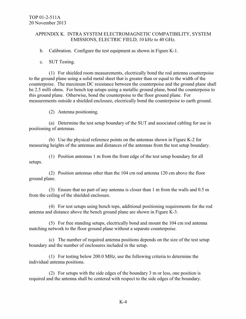
TOP 01-2-511A 20 November 2013
K-4
APPENDIX K. INTRA SYSTEM ELECTROMAGNETIC COMPATIBILITY, SYSTEM EMISSIONS, ELECTRIC FIELD, 10 kHz to 40 GHz.
b. Calibration. Configure the test equipment as shown in Figure K-1. c. SUT Testing. (1) For shielded room measurements, electrically bond the rod antenna counterpoise to the ground plane using a solid metal sheet that is greater than or equal to the width of the counterpoise. The maximum DC resistance between the counterpoise and the ground plane shall be 2.5 milli ohms. For bench top setups using a metallic ground plane, bond the counterpoise to this ground plane. Otherwise, bond the counterpoise to the floor ground plane. For measurements outside a shielded enclosure, electrically bond the counterpoise to earth ground. (2) Antenna positioning. (a) Determine the test setup boundary of the SUT and associated cabling for use in positioning of antennas. (b) Use the physical reference points on the antennas shown in Figure K-2 for measuring heights of the antennas and distances of the antennas from the test setup boundary. (1) Position antennas 1 m from the front edge of the test setup boundary for all setups. (2) Position antennas other than the 104 cm rod antenna 120 cm above the floor ground plane. (3) Ensure that no part of any antenna is closer than 1 m from the walls and 0.5 m from the ceiling of the shielded enclosure. (4) For test setups using bench tops, additional positioning requirements for the rod antenna and distance above the bench ground plane are shown in Figure K-3. (5) For free standing setups, electrically bond and mount the 104 cm rod antenna matching network to the floor ground plane without a separate counterpoise. (c) The number of required antenna positions depends on the size of the test setup boundary and the number of enclosures included in the setup. (1) For testing below 200.0 MHz, use the following criteria to determine the individual antenna positions.
(2) For setups with the side edges of the boundary 3 m or less, one position is required and the antenna shall be centered with respect to the side edges of the boundary.
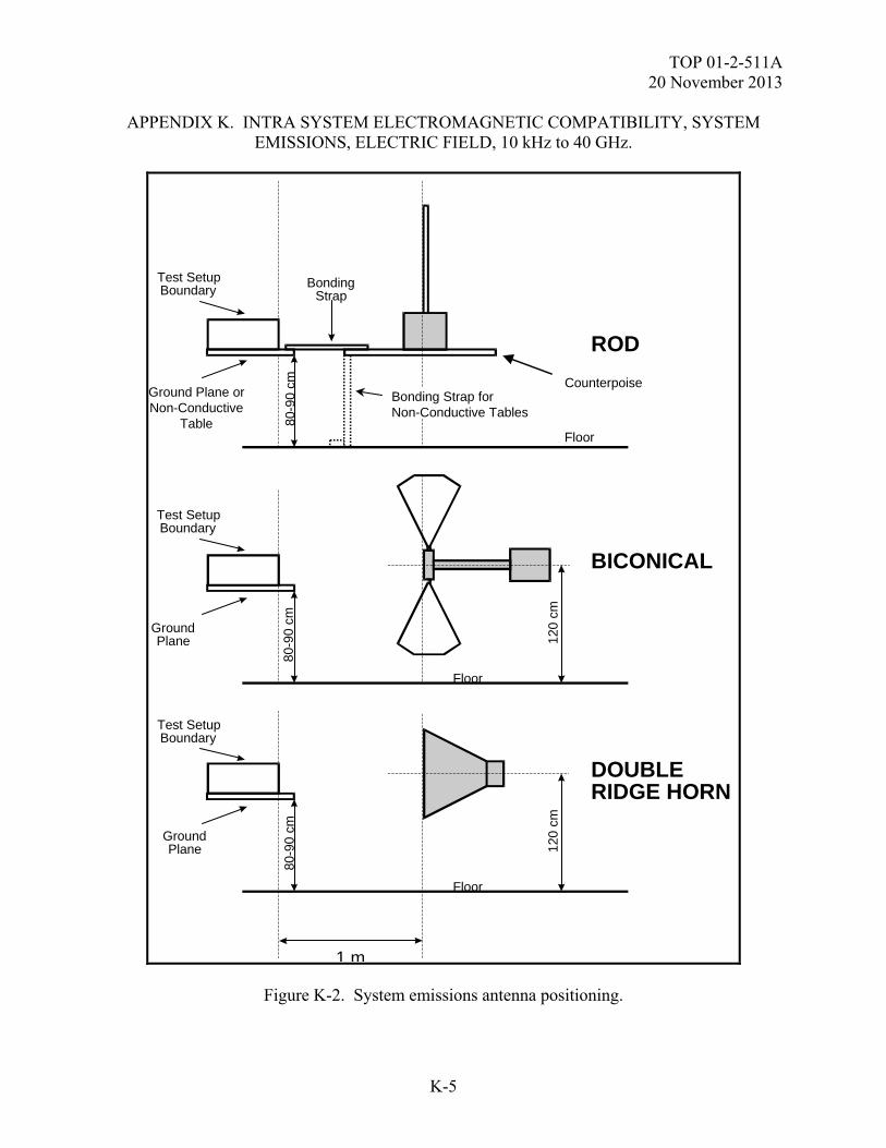
TOP 01-2-511A 20 November 2013
K-5
APPENDIX K. INTRA SYSTEM ELECTROMAGNETIC COMPATIBILITY, SYSTEM EMISSIONS, ELECTRIC FIELD, 10 kHz to 40 GHz.
1 m
ROD
BICONICAL
DOUBLERIDGE HORN
Test SetupBoundary
BondingStrap
Test SetupBoundary
Test SetupBoundary
GroundPlane
Counterpoise
GroundPlane
Floor
120
cm
80-9
0 cm
80-9
0 cm
Floor
120
cm
Floor
80-9
0 cm
Bonding Strap forNon-Conductive Tables
Ground Plane orNon-Conductive
Table
Figure K-2. System emissions antenna positioning.
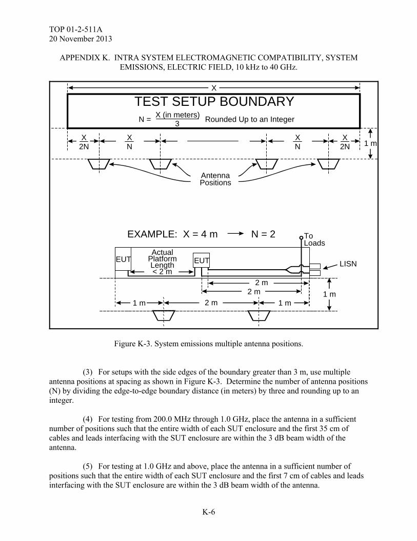
TOP 01-2-511A 20 November 2013
K-6
APPENDIX K. INTRA SYSTEM ELECTROMAGNETIC COMPATIBILITY, SYSTEM EMISSIONS, ELECTRIC FIELD, 10 kHz to 40 GHz.
AntennaPositions
XN
XN
X2N
X2N
TEST SETUP BOUNDARYX
3X (in meters)
N = Rounded Up to an Integer
EXAMPLE: X = 4 m N = 2
EUT EUT
1 m1 m1 m
2 m2 m
2 m
ActualPlatformLength< 2 m
ToLoads
LISN
1 m
Figure K-3. System emissions multiple antenna positions. (3) For setups with the side edges of the boundary greater than 3 m, use multiple antenna positions at spacing as shown in Figure K-3. Determine the number of antenna positions (N) by dividing the edge-to-edge boundary distance (in meters) by three and rounding up to an integer. (4) For testing from 200.0 MHz through 1.0 GHz, place the antenna in a sufficient number of positions such that the entire width of each SUT enclosure and the first 35 cm of cables and leads interfacing with the SUT enclosure are within the 3 dB beam width of the antenna. (5) For testing at 1.0 GHz and above, place the antenna in a sufficient number of positions such that the entire width of each SUT enclosure and the first 7 cm of cables and leads interfacing with the SUT enclosure are within the 3 dB beam width of the antenna.
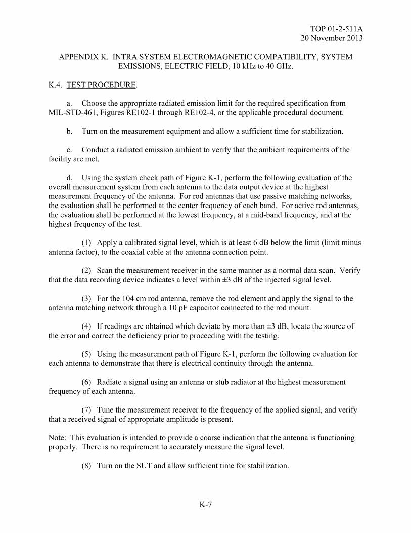
TOP 01-2-511A 20 November 2013
K-7
APPENDIX K. INTRA SYSTEM ELECTROMAGNETIC COMPATIBILITY, SYSTEM EMISSIONS, ELECTRIC FIELD, 10 kHz to 40 GHz.
K.4. TEST PROCEDURE. a. Choose the appropriate radiated emission limit for the required specification from MIL-STD-461, Figures RE102-1 through RE102-4, or the applicable procedural document. b. Turn on the measurement equipment and allow a sufficient time for stabilization. c. Conduct a radiated emission ambient to verify that the ambient requirements of the facility are met. d. Using the system check path of Figure K-1, perform the following evaluation of the overall measurement system from each antenna to the data output device at the highest measurement frequency of the antenna. For rod antennas that use passive matching networks, the evaluation shall be performed at the center frequency of each band. For active rod antennas, the evaluation shall be performed at the lowest frequency, at a mid-band frequency, and at the highest frequency of the test. (1) Apply a calibrated signal level, which is at least 6 dB below the limit (limit minus antenna factor), to the coaxial cable at the antenna connection point. (2) Scan the measurement receiver in the same manner as a normal data scan. Verify that the data recording device indicates a level within ±3 dB of the injected signal level. (3) For the 104 cm rod antenna, remove the rod element and apply the signal to the antenna matching network through a 10 pF capacitor connected to the rod mount. (4) If readings are obtained which deviate by more than ±3 dB, locate the source of the error and correct the deficiency prior to proceeding with the testing. (5) Using the measurement path of Figure K-1, perform the following evaluation for each antenna to demonstrate that there is electrical continuity through the antenna. (6) Radiate a signal using an antenna or stub radiator at the highest measurement frequency of each antenna. (7) Tune the measurement receiver to the frequency of the applied signal, and verify that a received signal of appropriate amplitude is present. Note: This evaluation is intended to provide a coarse indication that the antenna is functioning properly. There is no requirement to accurately measure the signal level. (8) Turn on the SUT and allow sufficient time for stabilization.
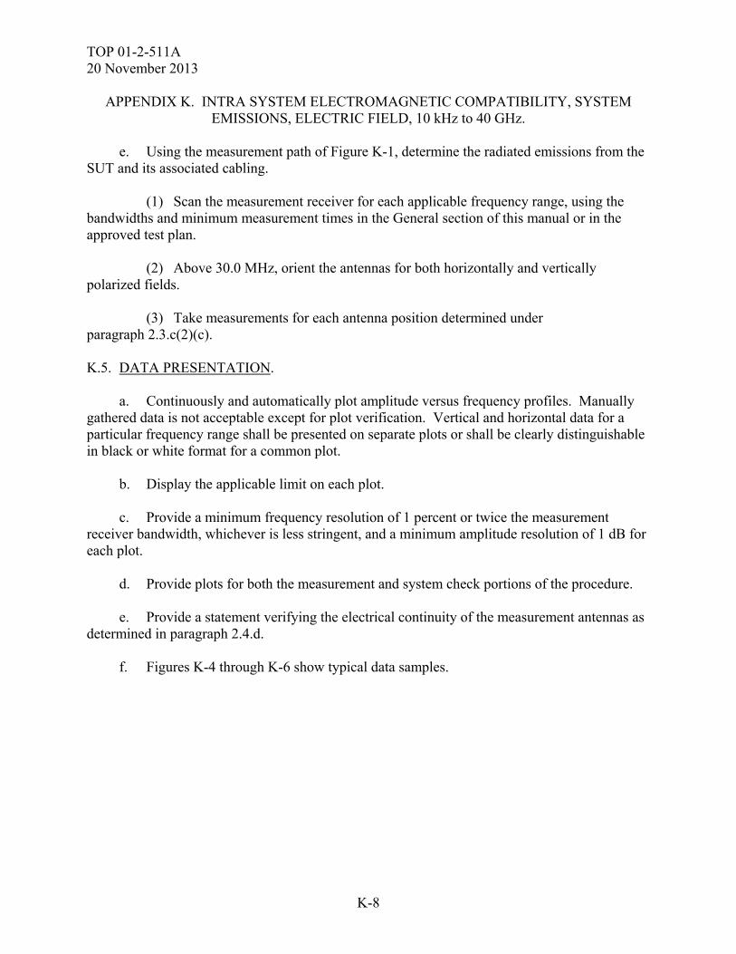
TOP 01-2-511A 20 November 2013
K-8
APPENDIX K. INTRA SYSTEM ELECTROMAGNETIC COMPATIBILITY, SYSTEM EMISSIONS, ELECTRIC FIELD, 10 kHz to 40 GHz.
e. Using the measurement path of Figure K-1, determine the radiated emissions from the SUT and its associated cabling. (1) Scan the measurement receiver for each applicable frequency range, using the bandwidths and minimum measurement times in the General section of this manual or in the approved test plan. (2) Above 30.0 MHz, orient the antennas for both horizontally and vertically polarized fields. (3) Take measurements for each antenna position determined under paragraph 2.3.c(2)(c). K.5. DATA PRESENTATION. a. Continuously and automatically plot amplitude versus frequency profiles. Manually gathered data is not acceptable except for plot verification. Vertical and horizontal data for a particular frequency range shall be presented on separate plots or shall be clearly distinguishable in black or white format for a common plot. b. Display the applicable limit on each plot. c. Provide a minimum frequency resolution of 1 percent or twice the measurement receiver bandwidth, whichever is less stringent, and a minimum amplitude resolution of 1 dB for each plot. d. Provide plots for both the measurement and system check portions of the procedure. e. Provide a statement verifying the electrical continuity of the measurement antennas as determined in paragraph 2.4.d. f. Figures K-4 through K-6 show typical data samples.
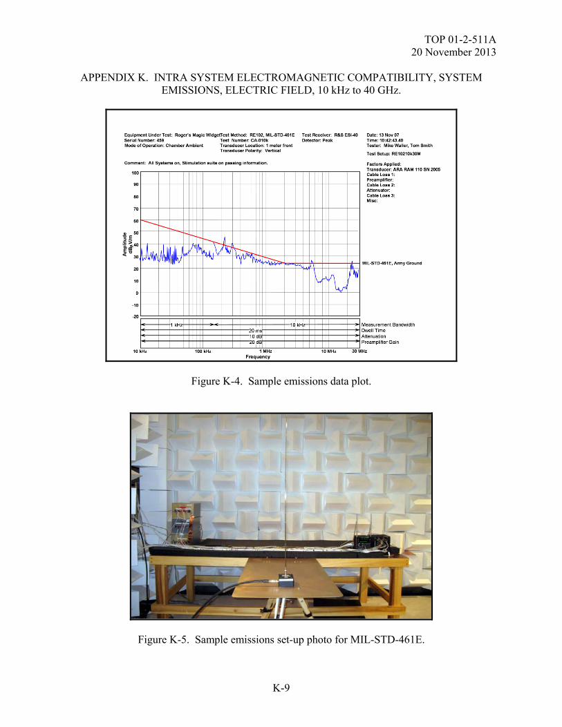
TOP 01-2-511A 20 November 2013
K-9
APPENDIX K. INTRA SYSTEM ELECTROMAGNETIC COMPATIBILITY, SYSTEM EMISSIONS, ELECTRIC FIELD, 10 kHz to 40 GHz.
Figure K-4. Sample emissions data plot.
Figure K-5. Sample emissions set-up photo for MIL-STD-461E.
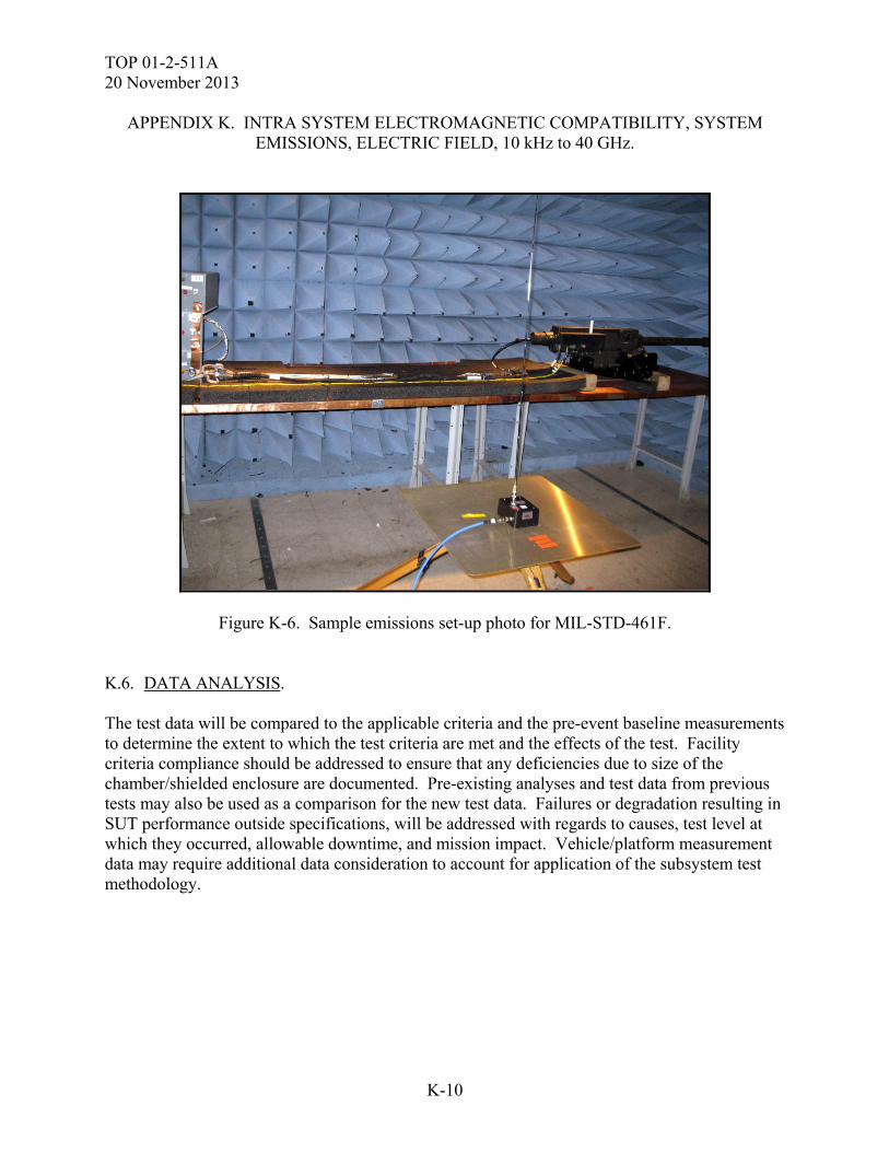
TOP 01-2-511A 20 November 2013
K-10
APPENDIX K. INTRA SYSTEM ELECTROMAGNETIC COMPATIBILITY, SYSTEM EMISSIONS, ELECTRIC FIELD, 10 kHz to 40 GHz.
Figure K-6. Sample emissions set-up photo for MIL-STD-461F. K.6. DATA ANALYSIS. The test data will be compared to the applicable criteria and the pre-event baseline measurements to determine the extent to which the test criteria are met and the effects of the test. Facility criteria compliance should be addressed to ensure that any deficiencies due to size of the chamber/shielded enclosure are documented. Pre-existing analyses and test data from previous tests may also be used as a comparison for the new test data. Failures or degradation resulting in SUT performance outside specifications, will be addressed with regards to causes, test level at which they occurred, allowable downtime, and mission impact. Vehicle/platform measurement data may require additional data consideration to account for application of the subsystem test methodology.
TOP 01-2-511A 20 November 2013
L-1
APPENDIX L. INTRA SYSTEM ELECTROMAGNETIC COMPATIBILITY (EMC) SOURCE/VICTIM.
L.1. APPLICABILITY. This test method is applicable to equipment at the system/sub-system level. This procedure provides the methods to evaluate the system/sub-systems in support of EMC. This Appendix is meant to act as a guide and is not a replacement for a test plan. L.2. REQUIREMENTS. The system shall be electromagnetically compatible within itself such that system operational performance requirements are met. Compliance shall be verified by system-level test, analysis, or a combination thereof. L.3. PURPOSE. The purpose of this test is to determine if there are any adverse interactions to subsystems and equipment with respect to performance and safety when additional subsystem or combinations of sub-systems on a platform are operated. This procedure can be applied to EIDs, where the EIDs are instrumented for HERO testing and monitored as a victim to all onboard emitters/electronics. L.4. TEST SETUP. L.4.1 Test Equipment. The following is a list of typical equipment used for this test: a. Baseband stimulation for transceiver systems; i.e., Bit Error tester, SINAD meter, Signal generator, and antenna systems. b. Antenna check equipment; i.e., directional coupler, loads, spectrum analyzer, signal generator, VSWR meter or power/watt meter. c. Network checking equipment; i.e., LAN taps, network analyzer. d. Weapons system diagnostics. e. Comparable system for real time checkouts of intrasystem compatibility. L.4.2 Set Up. a. It is recommended that the EMC test is performed in an electromagnetically quiet area as in an anechoic chamber, shielded enclosure, or an open area test site to minimize interference.
TOP 01-2-511A 20 November 2013
L-2
APPENDIX L. INTRA SYSTEM ELECTROMAGNETIC COMPATIBILITY (EMC) SOURCE/VICTIM.
b. A pre-test evaluation shall be performed to determine whether all of the SUT subsystems noted in the intrasystem compatibility matrix are operational. c. As part of the pre-test verify that the SUT onboard transmitter and antenna are functioning as required IAW manufactures specs. It is recommended that a transmission at a low, mid and high frequency is conducted. L.5. PROCEDURES. a. The system can be divided into multiple categories for the purposes of EMC testing as an example: non-C4ISR vehicle/platform systems, C4ISR computer and local area network (LAN) systems, C4ISR communications systems and weapons systems. (1) The vehicle/platform and communications are independent systems and can be operated and tested as individual components; i.e., Remote Weapons Station (RWS), Voice Intercom System (VIS), Single Channel Ground and Airborne Radio System (SINCGARS), and Enhanced Position Location Reporting System (EPLRS). (2) The computer and LAN system components are codependent items and must be treated as a one-victim group for the EMC testing. The Battlefield Functional Area Control System (BFACS), Force XXI Blue Force Tracker (BFT), routers, hubs, switches, etc, are considered components of the computer and LAN system. b. During the source/victim portion of EMC testing, the computer and LAN will be treated as a single-victim entity; however, the computer and LAN system components will be treated as individual source entities when testing for interference to the vehicle/platform and communications systems. The reasoning is that the computer and LAN components have individual power supplies and the greatest possibility of interference to the vehicle/platform and communications systems can be created by simply powering the computer and LAN components on. They do not have to be netted with other computer and LAN components to create interference potential. However, as a victim, the computer and LAN system must be netted with other components to establish a baseline performance level against which to check for interference-caused degradation. c. Calibration consists of system operation verification. d. SUT Testing. Each subsystem will be operated (sources of possible interference) and any effect on the other subsystems or victim group (victims of possible interference). Specific procedures will vary depending on the type of systems installed in the vehicle/platform. (1) Normal test operations will be as follows: (a) Turn on a selected subsystem, designated as the victim.
TOP 01-2-511A 20 November 2013
L-3
APPENDIX L. INTRA SYSTEM ELECTROMAGNETIC COMPATIBILITY (EMC) SOURCE/VICTIM.
(b) Turn on one of the other subsystems (source) after the victim sub-system or group has achieved stable operation. (c) Check the victim to determine whether any interference is being caused by operation of the source. (d) Turn off the source after results are noted and turn on the next source. (e) Repeat steps 2, through 4 until each source for that victim has been tested. (f) For receiver system perform a desensitization test starting with an all sources off condition to an all sources on condition. (2) Testing the SUT Transmitters as sources will be conducted as follows: (a) Turn off all equipment except the selected transmitter. (b) Turn on the selected victim subsystem and allow it to stabilize. Note: The victim will be operated in its normal mode of operation. If the victim has more than one mode of operation, it will be tested in all modes, or known worst case. (c) Set the transmitter to its normally used mode. (If more than one transmit mode is available do all modes, or worst case.) Set the transmitter to maximum transmitter output power. (d) Key the transmitter and allow sufficient amount of time to allow the victim to react to the presence of the electromagnetic energy. (e) Note on a data/record sheet any anomalous operation found. Record any information that will help to accurately describe the incompatibility. (f) Proceed to the next victim in the test matrix after the current victim is tested and repeat steps 2 through 7. (3) A final test of the sources can be conducted by powering on all sources and monitoring the victims. If an anomalous operation is found power OFF the sources until the victim is found. L.6. DATA PRESENTATION. Typical data collection sheets are shown in Tables L-1 and L-2.
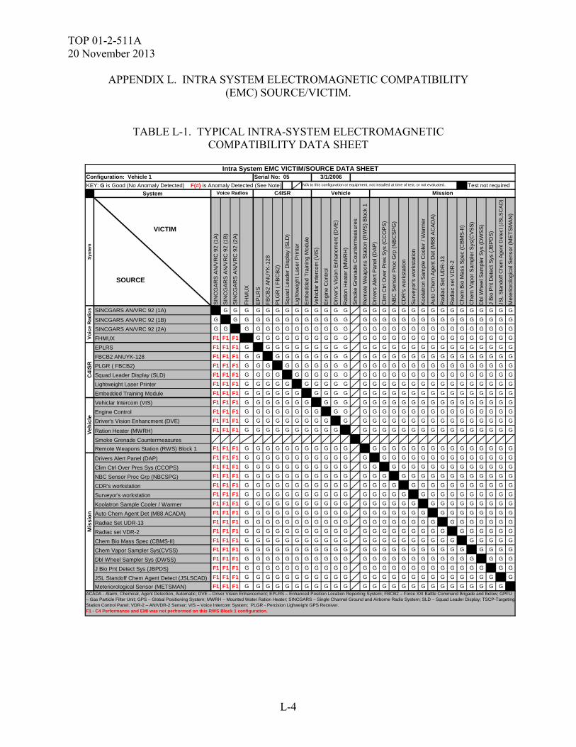
TOP 01-2-511A 20 November 2013
L-4
APPENDIX L. INTRA SYSTEM ELECTROMAGNETIC COMPATIBILITY (EMC) SOURCE/VICTIM.
TABLE L-1. TYPICAL INTRA-SYSTEM ELECTROMAGNETIC COMPATIBILITY DATA SHEET
KEY: G is Good (No Anomaly Detected) F(#) is Anomaly Detected (See Note) Test not required
System
Sys
tem
SIN
CG
AR
S A
N/V
RC
92
(1A
)
SIN
CG
AR
S A
N/V
RC
92
(1B
)
SIN
CG
AR
S A
N/V
RC
92
(2A
)
FH
MU
X
EP
LRS
FB
CB
2 A
NU
YK
-128
PL
GR
( F
BC
B2
)
Sq
uad
Lead
er D
ispl
ay
(SLD
)
Lig
htw
eig
ht L
ase
r P
rint
er
Em
bed
ded
Tra
inin
g M
od
ule
Ve
hicl
ar In
terc
om (
VIS
)
En
gine
Co
ntro
l
Dri
ver's
Vis
ion
Enh
ancm
ent (
DV
E)
Rat
ion
Hea
ter
(MW
RH
)
Sm
oke
Gre
nad
e C
oun
term
eas
ure
s
Rem
ote
Wea
pons
Sta
tion
(RW
S)
Blo
ck 1
Dri
vers
Ale
rt P
anel
(D
AP
)
Clim
Ctr
l Ove
r P
res
Sys
(C
CO
PS
)
NB
C S
ens
or
Pro
c G
rp (
NB
CS
PG
)
CD
R's
wor
ksta
tion
Su
rvey
or's
wo
rkst
atio
n
Ko
olat
ron
Sa
mpl
e C
oole
r /
Wa
rmer
Au
to C
hem
Age
nt D
et (
M8
8 A
CA
DA
)
Rad
iac
Set
UD
R-1
3
Ra
diac
se
t VD
R-2
Ch
em B
io M
ass
Sp
ec (
CB
MS
-II)
Ch
em V
apor
Sa
mp
ler
Sys
(CV
SS
)
Dbl
Whe
el S
am
pler
Sys
(D
WS
S)
J B
io P
nt D
ete
ct S
ys (
JBP
DS
)
JSL
Sta
ndof
f C
hem
Age
nt D
etec
t (J
SLS
CA
D)
Met
erio
rolo
gic
al S
ens
or
(ME
TS
MA
N)
SINCGARS AN/VRC 92 (1A) G G G G G G G G G G G G G G G G G G G G G G G G G G G G G
SINCGARS AN/VRC 92 (1B) G G G G G G G G G G G G G G G G G G G G G G G G G G G G G
SINCGARS AN/VRC 92 (2A) G G G G G G G G G G G G G G G G G G G G G G G G G G G G G
FHMUX F1 F1 F1 G G G G G G G G G G G G G G G G G G G G G G G G G G
EPLRS F1 F1 F1 G G G G G G G G G G G G G G G G G G G G G G G G G G
FBCB2 ANUYK-128 F1 F1 F1 G G G G G G G G G G G G G G G G G G G G G G G G G G
PLGR ( FBCB2) F1 F1 F1 G G G G G G G G G G G G G G G G G G G G G G G G G G
Squad Leader Display (SLD) F1 F1 F1 G G G G G G G G G G G G G G G G G G G G G G G G G G
Lightweight Laser Printer F1 F1 F1 G G G G G G G G G G G G G G G G G G G G G G G G G G
Embedded Training Module F1 F1 F1 G G G G G G G G G G G G G G G G G G G G G G G G G G
Vehiclar Intercom (VIS) F1 F1 F1 G G G G G G G G G G G G G G G G G G G G G G G G G G
Engine Control F1 F1 F1 G G G G G G G G G G G G G G G G G G G G G G G G G G
Driver's Vision Enhancment (DVE) F1 F1 F1 G G G G G G G G G G G G G G G G G G G G G G G G G G
Ration Heater (MWRH) F1 F1 F1 G G G G G G G G G G G G G G G G G G G G G G G G G G
Smoke Grenade Countermeasures
Remote Weapons Station (RWS) Block 1 F1 F1 F1 G G G G G G G G G G G G G G G G G G G G G G G G G G
Drivers Alert Panel (DAP) F1 F1 F1 G G G G G G G G G G G G G G G G G G G G G G G G G G
Clim Ctrl Over Pres Sys (CCOPS) F1 F1 F1 G G G G G G G G G G G G G G G G G G G G G G G G G G
NBC Sensor Proc Grp (NBCSPG) F1 F1 F1 G G G G G G G G G G G G G G G G G G G G G G G G G G
CDR's workstation F1 F1 F1 G G G G G G G G G G G G G G G G G G G G G G G G G G
Surveyor's workstation F1 F1 F1 G G G G G G G G G G G G G G G G G G G G G G G G G G
Koolatron Sample Cooler / Warmer F1 F1 F1 G G G G G G G G G G G G G G G G G G G G G G G G G G G
Auto Chem Agent Det (M88 ACADA) F1 F1 F1 G G G G G G G G G G G G G G G G G G G G G G G G G G
Radiac Set UDR-13 F1 F1 F1 G G G G G G G G G G G G G G G G G G G G G G G G G G
Radiac set VDR-2 F1 F1 F1 G G G G G G G G G G G G G G G G G G G G G G G G G G
Chem Bio Mass Spec (CBMS-II) F1 F1 F1 G G G G G G G G G G G G G G G G G G G G G G G G G G
Chem Vapor Sampler Sys(CVSS) F1 F1 F1 G G G G G G G G G G G G G G G G G G G G G G G G G G
Dbl Wheel Sampler Sys (DWSS) F1 F1 F1 G G G G G G G G G G G G G G G G G G G G G G G G G G
J Bio Pnt Detect Sys (JBPDS) F1 F1 F1 G G G G G G G G G G G G G G G G G G G G G G G G G G
JSL Standoff Chem Agent Detect (JSLSCAD) F1 F1 F1 G G G G G G G G G G G G G G G G G G G G G G G G G G
Meteriorological Sensor (METSMAN) F1 F1 F1 G G G G G G G G G G G G G G G G G G G G G G G G G G
Vo
ice
Ra
dio
sC
4IS
R
C4ISR
Configuration: Vehicle 1N/A to this configuration or equipment, not installed at time of test, or not evaluated..
Voice Radios
ACADA - Alarm, Chemical, Agent Detection, Automatic; DVE – Driver Vision Enhancement; EPLRS – Enhanced Position Location Reporting System; FBCB2 – Force XXI Battle Command Brigade and Below; GPFU – Gas Particle Filter Unit; GPS – Global Positioning System; MWRH – Mounted Water Ration Heater; SINCGARS – Single Channel Ground and Airborne Radio System; SLD – Squad Leader Display; TSCP-Targeting Station Control Panel; VDR-2 – AN/VDR-2 Sensor; VIS – Voice Intercom System; PLGR - Percision Lighweight GPS Receiver.F1 - C4 Performance and EMI was not perfrormed on this RWS Block 1 configuration.
Vehicle Mission
Serial No: 05 3/1/2006
Mis
sio
nV
eh
icle
Intra System EMC VICTIM/SOURCE DATA SHEET
SOURCE
VICTIM
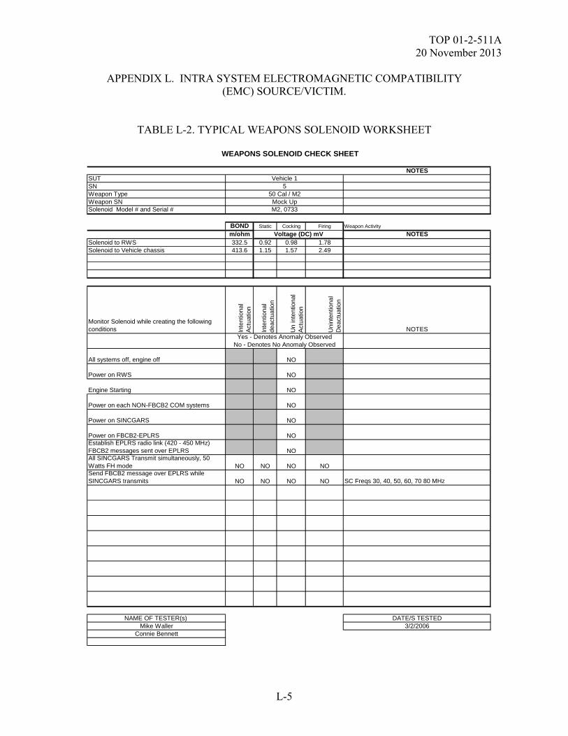
TOP 01-2-511A 20 November 2013
L-5
APPENDIX L. INTRA SYSTEM ELECTROMAGNETIC COMPATIBILITY (EMC) SOURCE/VICTIM.
TABLE L-2. TYPICAL WEAPONS SOLENOID WORKSHEET
NOTESSUTSNWeapon TypeWeapon SNSolenoid Model # and Serial #
BOND Static Cocking Firing Weapon Activity
m/ohm NOTESSolenoid to RWS 332.5 0.92 0.98 1.78Solenoid to Vehicle chassis 413.6 1.15 1.57 2.49
Monitor Solenoid while creating the following conditions In
tent
iona
l A
ctu
atio
n
Inte
ntio
nal
dea
ctua
tion
Un
inte
ntio
nal
Act
uat
ion
Uni
nten
tion
al
Dea
ctua
tion
NOTES
All systems off, engine off NO
Power on RWS NO
Engine Starting NO
Power on each NON-FBCB2 COM systems NO
Power on SINCGARS NO
Power on FBCB2-EPLRS NOEstablish EPLRS radio link (420 - 450 MHz) FBCB2 messages sent over EPLRS NOAll SINCGARS Transmit simultaneously, 50 Watts FH mode NO NO NO NOSend FBCB2 message over EPLRS while SINCGARS transmits NO NO NO NO SC Freqs 30, 40, 50, 60, 70 80 MHz
NAME OF TESTER(s) DATE/S TESTEDMike Waller 3/2/2006
Connie Bennett
Yes - Denotes Anomaly Observed No - Denotes No Anomaly Observed
WEAPONS SOLENOID CHECK SHEET
M2, 0733
Voltage (DC) mV
Vehicle 15
50 Cal / M2Mock Up

TOP 01-2-511A 20 November 2013
L-6
APPENDIX L. INTRA SYSTEM ELECTROMAGNETIC COMPATIBILITY (EMC) SOURCE/VICTIM.
L.7. DATA ANALYSIS PROCEDURE. The test data will be compared to the applicable criteria set forth in the SUT specification, and SUT test plan and the pre-event baseline measurements to determine the extent to which the test criteria are met and the effects of the EMC test environment on the SUT. Test anomalies will be assessed to determine if they should be classified as SUT failures and if so, further assessed with regards to causes, test parameters at which they occurred, mission impact and safety. Any effects found with respect to EIDs should be addressed with respect to safety of the associated weapon to include shielding and hardening methods as applicable.

TOP 01-2-511A 20 November 2013
M-1
APPENDIX M. PERSONNEL-BORNE ELECTROSTATIC DISCHARGE (PESD). M.1. APPLICABILITY. a. This Appendix provides general test methods to assess the safety and survivability of the SUT to the effects produced by a PESD. This Appendix is meant to act as a guide and is not a replacement for a test plan. b. The PESD environment is applicable to all subsystems, equipment, ordnance EIDs and firing circuits, including those installed external to aircraft IAW the equipment specification. c. PESD environment testing may be applicable at either or both the equipment system level and the component level IAW the equipment specification. The PESD environment is applied to points on the SUT which may be contacted by personnel during the different configurations / modes of operation including operations, shipping, storage, loading/un-loading and maintenance. M.2. REQUIREMENTS. a. When exposed to the PESD environment, the SUT (and its platform, if any) shall meet the performance requirements detailed in their equipment specifications and test plan. A typical SUT PESD requirement is as follows. When the SUT is not flight or safety critical, often the “during and” is removed from the performance part of the requirement. b. The SUT, when in the ground handling, storage, transport, and operational configurations, shall remain safe during and after exposure to the PESD environment, and meet its performance requirements during and after exposure to the PESD environment, with parameters specified by MIL-STD-464C, Paragraphs 5.8.3 and 5.8.4. Discharges shall be to any point on the SUT that may be contacted by personnel during operation, transport, storage, and maintenance. c. The simulated PESD environment is defined in MIL-STD-464C, Paragraph 5.8.3 for Ordnance Systems and 5.8.4 for Electrical and Electronic Systems. The PESD test pulse parameters, detailed in Tables M-1 and M-2, standardize the PESD pulse and simulate the equivalent circuit of a person from which the electrostatic discharge may take place.
TABLE M-1. PESD ENVIRONMENT PARAMETERS FOR ORDNANCE
VOLTAGE CAPACITANCE SERIES RESISTANCE
± 25,000 ± 500 Volts 500 ± 5% pF 500 ± 5% Ω
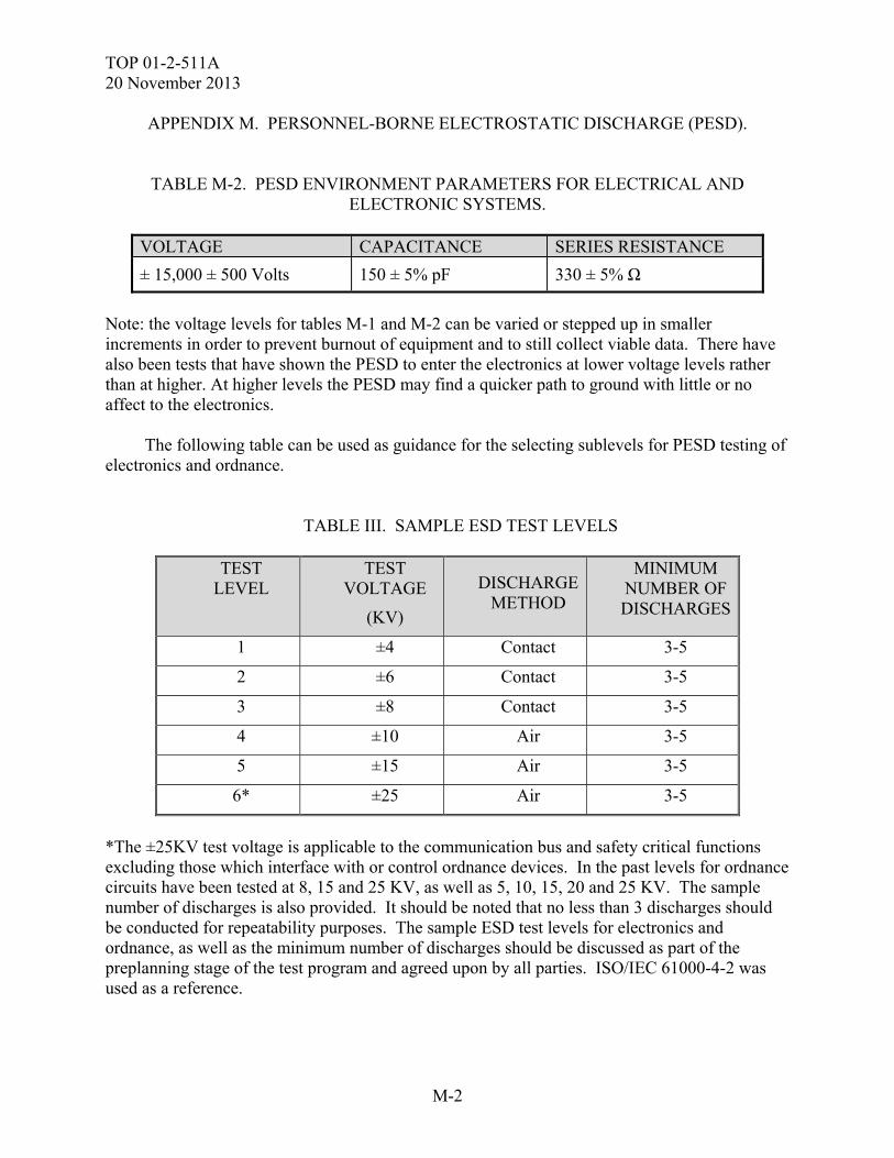
TOP 01-2-511A 20 November 2013
M-2
APPENDIX M. PERSONNEL-BORNE ELECTROSTATIC DISCHARGE (PESD).
TABLE M-2. PESD ENVIRONMENT PARAMETERS FOR ELECTRICAL AND ELECTRONIC SYSTEMS.
VOLTAGE CAPACITANCE SERIES RESISTANCE
± 15,000 ± 500 Volts 150 ± 5% pF 330 ± 5% Ω
Note: the voltage levels for tables M-1 and M-2 can be varied or stepped up in smaller increments in order to prevent burnout of equipment and to still collect viable data. There have also been tests that have shown the PESD to enter the electronics at lower voltage levels rather than at higher. At higher levels the PESD may find a quicker path to ground with little or no affect to the electronics. The following table can be used as guidance for the selecting sublevels for PESD testing of electronics and ordnance.
TABLE III. SAMPLE ESD TEST LEVELS
TEST LEVEL
TEST VOLTAGE
(KV)
DISCHARGE METHOD
MINIMUM NUMBER OF DISCHARGES
1 ±4 Contact 3-5
2 ±6 Contact 3-5
3 ±8 Contact 3-5
4 ±10 Air 3-5
5 ±15 Air 3-5
6* ±25 Air 3-5
*The ±25KV test voltage is applicable to the communication bus and safety critical functions excluding those which interface with or control ordnance devices. In the past levels for ordnance circuits have been tested at 8, 15 and 25 KV, as well as 5, 10, 15, 20 and 25 KV. The sample number of discharges is also provided. It should be noted that no less than 3 discharges should be conducted for repeatability purposes. The sample ESD test levels for electronics and ordnance, as well as the minimum number of discharges should be discussed as part of the preplanning stage of the test program and agreed upon by all parties. ISO/IEC 61000-4-2 was used as a reference.
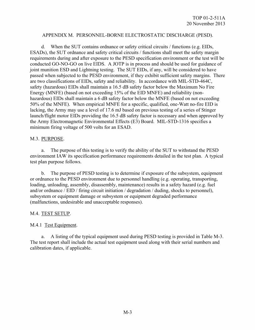
TOP 01-2-511A 20 November 2013
M-3
APPENDIX M. PERSONNEL-BORNE ELECTROSTATIC DISCHARGE (PESD). d. When the SUT contains ordnance or safety critical circuits / functions (e.g. EIDs, ESADs), the SUT ordnance and safety critical circuits / functions shall meet the safety margin requirements during and after exposure to the PESD specification environment or the test will be conducted GO-NO-GO on live EIDS. A JOTP is in process and should be used for guidance of joint munition ESD and Lightning testing. The SUT EIDs, if any, will be considered to have passed when subjected to the PESD environment, if they exhibit sufficient safety margins. There are two classifications of EIDs, safety and reliability. In accordance with MIL-STD-464C, safety (hazardous) EIDs shall maintain a 16.5 dB safety factor below the Maximum No Fire Energy (MNFE) (based on not exceeding 15% of the EID MNFE) and reliability (non-hazardous) EIDs shall maintain a 6 dB safety factor below the MNFE (based on not exceeding 50% of the MNFE). When empirical MNFE for a specific, qualified, one-Watt no-fire EID is lacking, the Army may use a level of 17.6 mJ based on previous testing of a series of Stinger launch/flight motor EIDs providing the 16.5 dB safety factor is necessary and when approved by the Army Electromagnetic Environmental Effects (E3) Board. MIL-STD-1316 specifies a minimum firing voltage of 500 volts for an ESAD. M.3. PURPOSE. a. The purpose of this testing is to verify the ability of the SUT to withstand the PESD environment IAW its specification performance requirements detailed in the test plan. A typical test plan purpose follows. b. The purpose of PESD testing is to determine if exposure of the subsystem, equipment or ordnance to the PESD environment due to personnel handling (e.g. operating, transporting, loading, unloading, assembly, disassembly, maintenance) results in a safety hazard (e.g. fuel and/or ordnance / EID / firing circuit initiation / degradation / duding, shocks to personnel), subsystem or equipment damage or subsystem or equipment degraded performance (malfunctions, undesirable and unacceptable responses). M.4. TEST SETUP. M.4.1 Test Equipment. a. A listing of the typical equipment used during PESD testing is provided in Table M-3. The test report shall include the actual test equipment used along with their serial numbers and calibration dates, if applicable.
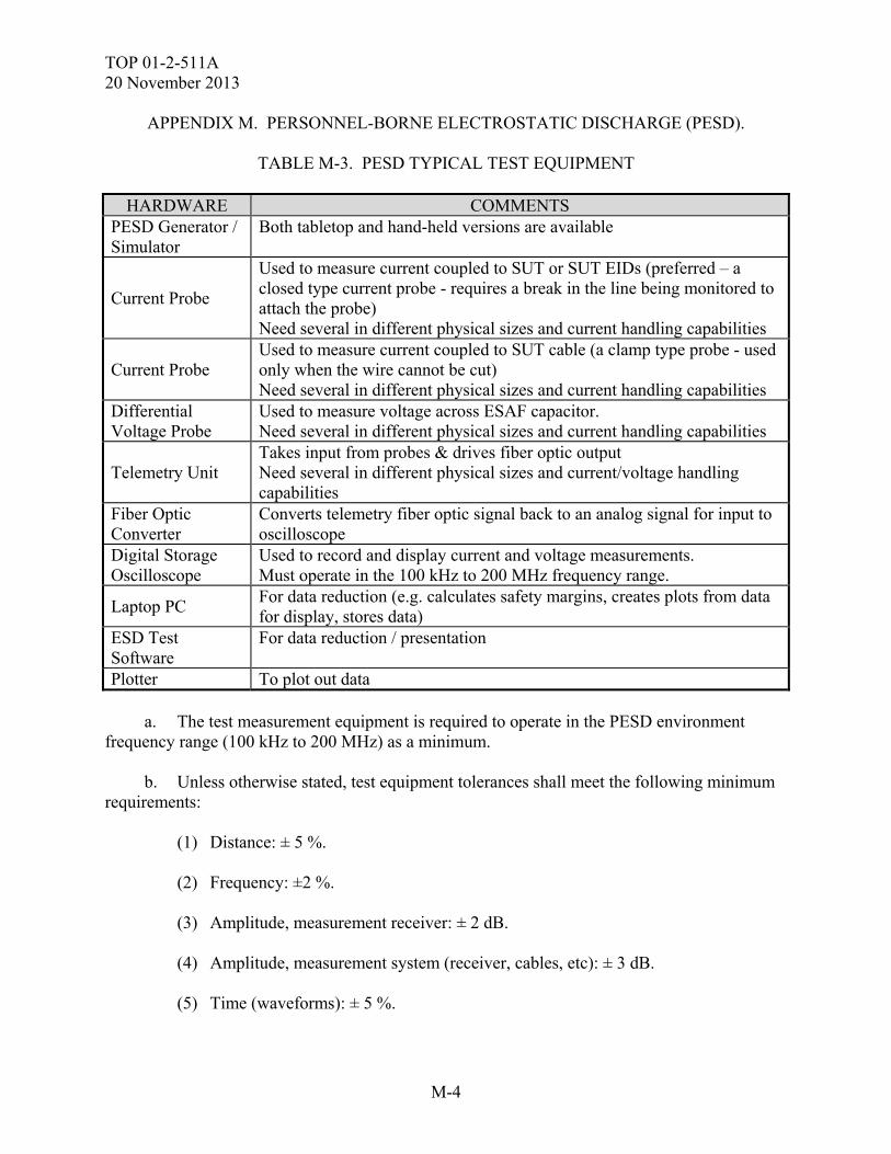
TOP 01-2-511A 20 November 2013
M-4
APPENDIX M. PERSONNEL-BORNE ELECTROSTATIC DISCHARGE (PESD).
TABLE M-3. PESD TYPICAL TEST EQUIPMENT
HARDWARE COMMENTS PESD Generator / Simulator
Both tabletop and hand-held versions are available
Current Probe
Used to measure current coupled to SUT or SUT EIDs (preferred – a closed type current probe - requires a break in the line being monitored to attach the probe) Need several in different physical sizes and current handling capabilities
Current Probe Used to measure current coupled to SUT cable (a clamp type probe - used only when the wire cannot be cut) Need several in different physical sizes and current handling capabilities
Differential Voltage Probe
Used to measure voltage across ESAF capacitor. Need several in different physical sizes and current handling capabilities
Telemetry Unit Takes input from probes & drives fiber optic output Need several in different physical sizes and current/voltage handling capabilities
Fiber Optic Converter
Converts telemetry fiber optic signal back to an analog signal for input to oscilloscope
Digital Storage Oscilloscope
Used to record and display current and voltage measurements. Must operate in the 100 kHz to 200 MHz frequency range.
Laptop PC For data reduction (e.g. calculates safety margins, creates plots from data for display, stores data)
ESD Test Software
For data reduction / presentation
Plotter To plot out data a. The test measurement equipment is required to operate in the PESD environment frequency range (100 kHz to 200 MHz) as a minimum. b. Unless otherwise stated, test equipment tolerances shall meet the following minimum requirements: (1) Distance: ± 5 %. (2) Frequency: ±2 %. (3) Amplitude, measurement receiver: ± 2 dB. (4) Amplitude, measurement system (receiver, cables, etc): ± 3 dB. (5) Time (waveforms): ± 5 %.
TOP 01-2-511A 20 November 2013
M-5
APPENDIX M. PERSONNEL-BORNE ELECTROSTATIC DISCHARGE (PESD). (6) Resistors: ± 5 %. (7) Capacitors: ± 20 %. c. Test software used, including measurement system software, SUT software, instrumentation and test set software shall be documented as to dates, developer, version number, etc. M.4.2 Instrumentation. SUT instrumentation is permissible but it shall not influence test results. To minimize the possibility of instrumentation influencing test results or instrumentation susceptibility: a. Use fiber-optic based instrumentation whenever possible. b. Use twisted, shielded pair wiring when conductive leads are required. c. Instrumentation equipment and its leads should be buried inside the SUT with only the fiber optic leads exiting the SUT. M.4.3 Instrumentation May Include the Following: a. Current probes to measure the stimulus current waveforms to determine the adequacy of the simulated PESD environment. b. Cameras connected to monitors in a shielded instrumentation room using fiber optic lines. The cameras may be placed within shielded enclosures. c. Test sets may be used to check out the SUT before and after each test event but should be removed from the test setup for PESD testing (if not used during the test event). If required during testing, test sets should be protected from the test environment and placed as far away from the strike point as possible. Any test set interface cabling should be well shielded and emplaced radially away from the strike point to minimize coupling. d. SUT instrumentation typically consists of current probes to measure the current coupled to one or more SUT wires / cables due to the PESD environment and/or voltage probes to measure a firing capacitor voltage. e. EIDs and ESAFs may be instrumented to determine safety margins (see Figure M-1) using current and voltage probes.
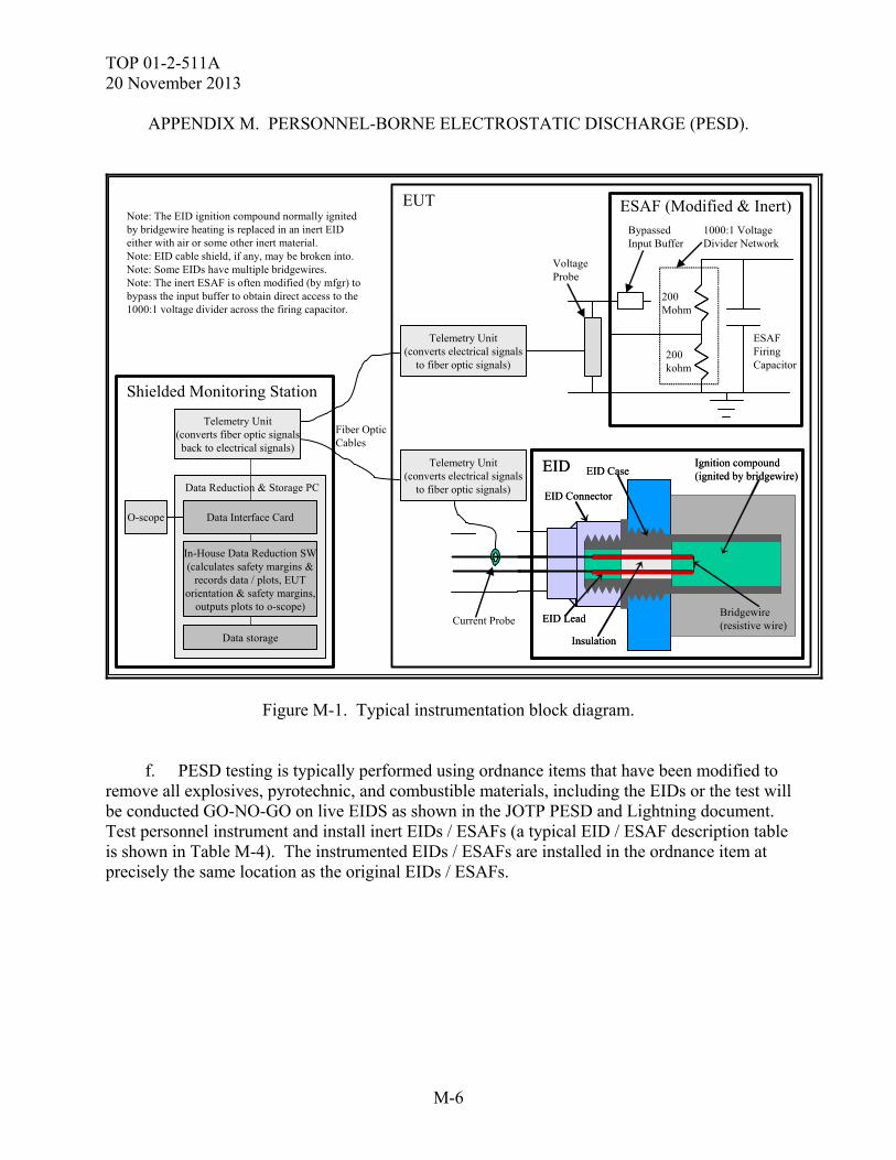
TOP 01-2-511A 20 November 2013
M-6
APPENDIX M. PERSONNEL-BORNE ELECTROSTATIC DISCHARGE (PESD).
Shielded Monitoring Station
Fiber OpticCables
Data Reduction & Storage PC
Data Interface Card
In-House Data Reduction SW(calculates safety margins &
records data / plots, EUTorientation & safety margins,
outputs plots to o-scope)
Data storage
Note: The EID ignition compound normally ignitedby bridgewire heating is replaced in an inert EIDeither with air or some other inert material.Note: EID cable shield, if any, may be broken into.Note: Some EIDs have multiple bridgewires.Note: The inert ESAF is often modified (by mfgr) tobypass the input buffer to obtain direct access to the1000:1 voltage divider across the firing capacitor.
EID
Bridgewire(resistive wire)
EID Connector
Insulation
EID Lead
EID CaseIgnition compound(ignited by bridgewire)
EID
Bridgewire(resistive wire)
EID Connector
Insulation
EID Lead
EID CaseIgnition compound(ignited by bridgewire)
ESAF (Modified & Inert)
ESAFFiringCapacitor
BypassedInput Buffer
200Mohm
200kohm
1000:1 VoltageDivider Network
Current Probe
VoltageProbe
Telemetry Unit(converts electrical signals
to fiber optic signals)
Telemetry Unit(converts electrical signals
to fiber optic signals)
EUT
O-scope
Telemetry Unit(converts fiber optic signalsback to electrical signals)
Figure M-1. Typical instrumentation block diagram. f. PESD testing is typically performed using ordnance items that have been modified to remove all explosives, pyrotechnic, and combustible materials, including the EIDs or the test will be conducted GO-NO-GO on live EIDS as shown in the JOTP PESD and Lightning document. Test personnel instrument and install inert EIDs / ESAFs (a typical EID / ESAF description table is shown in Table M-4). The instrumented EIDs / ESAFs are installed in the ordnance item at precisely the same location as the original EIDs / ESAFs.
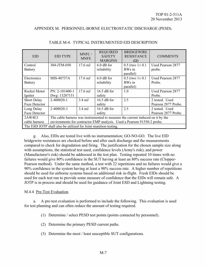
TOP 01-2-511A 20 November 2013
M-7
APPENDIX M. PERSONNEL-BORNE ELECTROSTATIC DISCHARGE (PESD).
TABLE M-4. TYPICAL INSTRUMENTED EID DESCRIPTION
EID EID TYPE MNFC / MNFE
REQUIRED SAFETY
MARGINS
BRIDGEWIRE RESISTANCE
(Ω) COMMENTS
Control Battery
304-JTM-050 17.6 mJ 6.0 dB for reliability
0.5 (two 1± 0.1 BWs in parallel)
Used Pearson 2877 probe.
Electronics Battery
MIS-40737A 17.6 mJ 6.0 dB for reliability
0.5 (two 1± 0.1 BWs in parallel)
Used Pearson 2877 Probe.
Rocket Motor Igniter
PN: 2-101400-1 Dwg: 13287151
17.6 mJ 16.5 dB for safety
1.0 Used Pearson 2877 Probe.
Short Delay Fuze Detector
2-400020-1 3.4 mJ 16.5 dB for safety
2.5 2 tested. Used Pearson 2877 Probe.
Long Delay Fuze Detector
2-400020-3 3.4 mJ 16.5 dB for safety
2.5 2 tested. Used Pearson 2877 Probe.
2AW4E3 cable harness
The cable harness was instrumented to measure the current induced on it by the environments for contractor EMP analysis. Used a Pearson 91550-2 probe.
The ESD JOTP shall also be utilized for Joint munition testing. g. Also, EIDs are tested live with no instrumentation; GO-NO-GO. The live EID bridgewire resistances are checked before and after each discharge and the measurements compared to check for degradation and firing. The justification for the chosen sample size along with assumptions, the statistical test used, confidence levels (Army's risk), and power (Manufacturer's risk) should be addressed in the test plan. Testing repeated 10 times with no failures would give 80% confidence in the SUT having at least an 80% success rate (Clopper-Pearson method). Under the same method, a test with 22 repetitions and no failures would give a 90% confidence in the system having at least a 90% success rate. A higher number of repetitions should be used for airborne systems based on additional risk in-flight. Fresh EIDs should be used for each test run to provide some measure of confidence that the EIDs will remain safe. A JOTP is in process and should be used for guidance of Joint ESD and Lightning testing. M.4.4 Pre-Test Evaluation. a. A pre-test evaluation is performed to include the following. This evaluation is used for test planning and can often reduce the amount of testing required. (1) Determine / select PESD test points (points contacted by personnel). (2) Determine the primary PESD current paths. (3) Determine the most / least susceptible SUT configurations.
TOP 01-2-511A 20 November 2013
M-8
APPENDIX M. PERSONNEL-BORNE ELECTROSTATIC DISCHARGE (PESD). (4) Determine the most / least susceptible SUT modes of operation. (5) Determine the probable POEs. (6) Determine the bulk current measurement points. (7) Perform an energy coupling analysis to identify the type and capability requirements for the data acquisition system. Usually, clamp-on non-obtrusive current probes are used to not affect the inherent shielding integrity of the cable or the SUT shielding integrity. (8) Determine critical SUT data required to be instrumented and monitored. (9) Determine which EIDs are to be instrumented and measured and how. (10) Determine SUT/platform critical functions and circuits. (11) Determine SUT PESD protection features and their predicted performance and whether they are repairable or replaceable. (12) Determine verification and pass/fail criteria and required safety margins. (13) Determine the SUT operating and check-out procedures. b. Pre-existing analyses and test data from previous tests may be evaluated and incorporated into the test planning and pre-test analysis in order to enhance and reduce the scope of the new testing. M.4.5 Setup. Test setups vary. Some typical test setup photographs are shown in Figures M-2 and M-3. Following are general / typical test setup guidelines. a. PESD testing utilizes a PESD charge generator designed to discharge IAW the required test parameters. The PESD environment is generated by discharging the voltage on a capacitor through a resistor onto the SUT test points. b. Fast response probes are used to monitor current, voltages, and the test energy. Telemetry units are used to convert the electrical signals to optical signals and transmit them over fiber optic lines to a receiver in a shielded area where they are converted back to electrical signals, processed, observed (monitored on a digitizing oscilloscope), and recorded on a PC laptop for data reduction. Test data reduction software extracts the desired test parameters, calculates the EID safety margins, plots the data and creates plots.
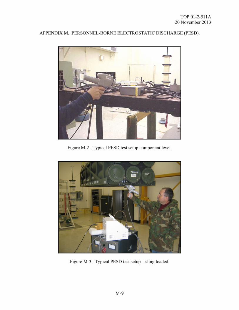
TOP 01-2-511A 20 November 2013
M-9
APPENDIX M. PERSONNEL-BORNE ELECTROSTATIC DISCHARGE (PESD).
Figure M-2. Typical PESD test setup component level.
Figure M-3. Typical PESD test setup – sling loaded.
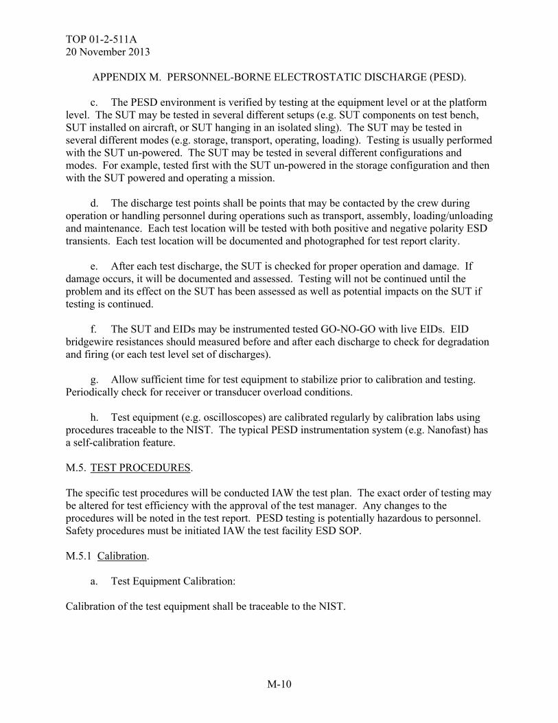
TOP 01-2-511A 20 November 2013
M-10
APPENDIX M. PERSONNEL-BORNE ELECTROSTATIC DISCHARGE (PESD).
c. The PESD environment is verified by testing at the equipment level or at the platform level. The SUT may be tested in several different setups (e.g. SUT components on test bench, SUT installed on aircraft, or SUT hanging in an isolated sling). The SUT may be tested in several different modes (e.g. storage, transport, operating, loading). Testing is usually performed with the SUT un-powered. The SUT may be tested in several different configurations and modes. For example, tested first with the SUT un-powered in the storage configuration and then with the SUT powered and operating a mission. d. The discharge test points shall be points that may be contacted by the crew during operation or handling personnel during operations such as transport, assembly, loading/unloading and maintenance. Each test location will be tested with both positive and negative polarity ESD transients. Each test location will be documented and photographed for test report clarity. e. After each test discharge, the SUT is checked for proper operation and damage. If damage occurs, it will be documented and assessed. Testing will not be continued until the problem and its effect on the SUT has been assessed as well as potential impacts on the SUT if testing is continued. f. The SUT and EIDs may be instrumented tested GO-NO-GO with live EIDs. EID bridgewire resistances should measured before and after each discharge to check for degradation and firing (or each test level set of discharges). g. Allow sufficient time for test equipment to stabilize prior to calibration and testing. Periodically check for receiver or transducer overload conditions. h. Test equipment (e.g. oscilloscopes) are calibrated regularly by calibration labs using procedures traceable to the NIST. The typical PESD instrumentation system (e.g. Nanofast) has a self-calibration feature. M.5. TEST PROCEDURES. The specific test procedures will be conducted IAW the test plan. The exact order of testing may be altered for test efficiency with the approval of the test manager. Any changes to the procedures will be noted in the test report. PESD testing is potentially hazardous to personnel. Safety procedures must be initiated IAW the test facility ESD SOP. M.5.1 Calibration. a. Test Equipment Calibration: Calibration of the test equipment shall be traceable to the NIST.
TOP 01-2-511A 20 November 2013
M-11
APPENDIX M. PERSONNEL-BORNE ELECTROSTATIC DISCHARGE (PESD). b. PESD Test Setup Calibration (to verify specification waveform parameters): (1) Set up the PESD simulator with settings that past experience has shown to discharge per the specification waveform parameters. (2) Secure the test area and insure personnel are at a safe distance. (3) Charge up the PESD simulator to the positive specification level. (4) Discharge the PESD simulator to the ground return line. Repeat, adjusting the PESD simulator until the PESD criteria is obtained. (5) Record the PESD simulator calibration settings. (6) Repeat calibration for the negative specification level. (7) Verify that the PESD simulator is in a safe configuration. M.5.2 EID Instrumentation Calibration. a. Check instrumentation operation for the SUT, EIDs, ESAFs, etc. b. Test EIDs and their associated firing circuit continuity and operation. c. Exercise instrumentation self-calibration features, if available. M.5.3 Test. a. Set up the SUT for PESD testing using the same test equipment and settings used during calibration. Set up the instrumentation equipment (e.g. to monitor EID current / energy coupling), if applicable. Electrically isolate the SUT. b. Connect the instrumentation to the data processing/collection system (oscilloscope and PC) using the telemetry system and fiber optic cables. c. Place the SUT in a test plan matrix specified configuration and mode. d. Verify data acquisition and instrumentation equipment operation. e. Power the SUT ON, run pre-test baseline functional checks. f. Secure the test area and insure that personnel are at a safe distance.
TOP 01-2-511A 20 November 2013
M-12
APPENDIX M. PERSONNEL-BORNE ELECTROSTATIC DISCHARGE (PESD). g. Charge PESD probe to the positive specification level using the settings determined during calibration. h. Move the PESD probe toward a test point until discharge occurs. i. Verify PESD simulator is in a safe configuration. j. After each discharge, examine the data to ensure that the PESD criteria were simulated, the test data is adequate, and the data is within pass/fail criteria. Calculate safety margins or, measure live EID bridgewire resistance as required. k. After each discharge, perform a visual check for PESD induced SUT damage. l. After each discharge, repeat SUT operational checks and compare to baseline. m. If there are susceptibilities, determine the SUT components affected the required steps to recovery (e.g. cycling power) and the recovery time. If possible (if SUT not damaged), verify the repeatability of the susceptibility and determine the threshold and safety margins, if necessary. n. Record the following for each discharge and mark on plots. (1) Stimulus waveform parameter data / plots. (2) Test configuration / test mode. (3) Test discharge point. (4) Post-discharge functional check pass/fail results. (5) Visual damage inspection results. (6) SUT responses (e.g. components affected, wire/cable currents, EID currents, SUT upsets, recovery times, etc.). (7) EIDs monitored their calculated SMs and whether they met requirements. (8) EID bridgewire resistance and determination of degradation, if required. (9) Date, time, location. o. Repeat the test procedure for the negative PESD transient. p. Repeat the test procedure for all test discharge points.
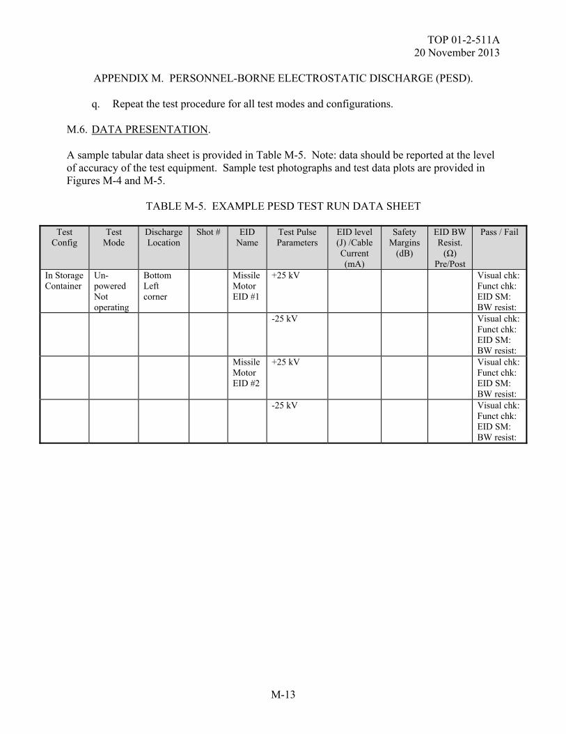
TOP 01-2-511A 20 November 2013
M-13
APPENDIX M. PERSONNEL-BORNE ELECTROSTATIC DISCHARGE (PESD). q. Repeat the test procedure for all test modes and configurations. M.6. DATA PRESENTATION. A sample tabular data sheet is provided in Table M-5. Note: data should be reported at the level of accuracy of the test equipment. Sample test photographs and test data plots are provided in Figures M-4 and M-5.
TABLE M-5. EXAMPLE PESD TEST RUN DATA SHEET
Test
Config Test
Mode Discharge Location
Shot # EID Name
Test Pulse Parameters
EID level (J) /Cable Current (mA)
Safety Margins
(dB)
EID BW Resist.
(Ω) Pre/Post
Pass / Fail
In Storage Container
Un-powered Not operating
Bottom Left corner
Missile Motor EID #1
+25 kV Visual chk: Funct chk: EID SM: BW resist:
-25 kV Visual chk: Funct chk: EID SM: BW resist:
Missile Motor EID #2
+25 kV Visual chk: Funct chk: EID SM: BW resist:
-25 kV Visual chk: Funct chk: EID SM: BW resist:
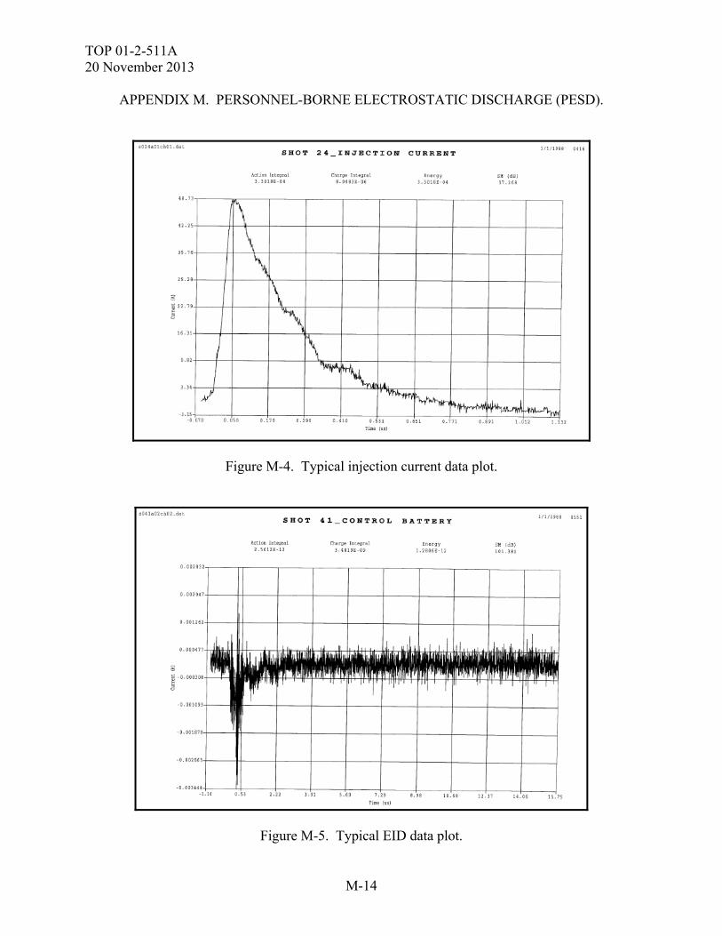
TOP 01-2-511A 20 November 2013
M-14
APPENDIX M. PERSONNEL-BORNE ELECTROSTATIC DISCHARGE (PESD).
Figure M-4. Typical injection current data plot.
Figure M-5. Typical EID data plot.
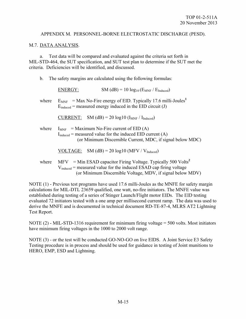
TOP 01-2-511A 20 November 2013
M-15
APPENDIX M. PERSONNEL-BORNE ELECTROSTATIC DISCHARGE (PESD). M.7. DATA ANALYSIS. a. Test data will be compared and evaluated against the criteria set forth in MIL-STD-464, the SUT specification, and SUT test plan to determine if the SUT met the criteria. Deficiencies will be identified, and discussed. b. The safety margins are calculated using the following formulas: ENERGY: SM (dB) = 10 log10 (EMNF / EInduced) where EMNF = Max No-Fire energy of EID. Typically 17.6 milli-Joules1 Einduced = measured energy induced in the EID circuit (J) CURRENT: SM (dB) = 20 log10 (IMNF / IInduced) where IMNF = Maximum No-Fire current of EID (A) Iinduced = measured value for the induced EID current (A) (or Minimum Discernible Current, MDC, if signal below MDC) VOLTAGE: SM (dB) = 20 log10 (MFV / VInduced) where MFV = Min ESAD capacitor Firing Voltage. Typically 500 Volts2 Vinduced = measured value for the induced ESAD cap firing voltage (or Minimum Discernible Voltage, MDV, if signal below MDV) NOTE (1) - Previous test programs have used 17.6 milli-Joules as the MNFE for safety margin calculations for MIL-DTL 23659 qualified, one watt, no-fire initiators. The MNFE value was established during testing of a series of Stinger Launch/Flight motor EIDs. The EID testing evaluated 72 initiators tested with a one amp per millisecond current ramp. The data was used to derive the MNFE and is documented in technical document RD-TE-87-4, MLRS AT2 Lightning Test Report. NOTE (2) - MIL-STD-1316 requirement for minimum firing voltage = 500 volts. Most initiators have minimum firing voltages in the 1000 to 2000 volt range. NOTE (3) - or the test will be conducted GO-NO-GO on live EIDS. A Joint Service E3 Safety Testing procedure is in process and should be used for guidance in testing of Joint munitions to HERO, EMP, ESD and Lightning.
TOP 01-2-511A 20 November 2013
M-16
APPENDIX M. PERSONNEL-BORNE ELECTROSTATIC DISCHARGE (PESD). c. The test data will be compared to the applicable criteria set forth in MIL-STD 464C, the SUT specification, and SUT test plan and the pre-event baseline measurements to determine the extent to which the test criteria are met and the effects of the PESD test environment on the SUT. Test anomalies will be assessed to determine if they should be classified as SUT failures and if so, further assessed with regards to causes, test parameters at which they occurred, mission impact and safety. Safety margins will be calculated and compared to the criteria, as necessary.
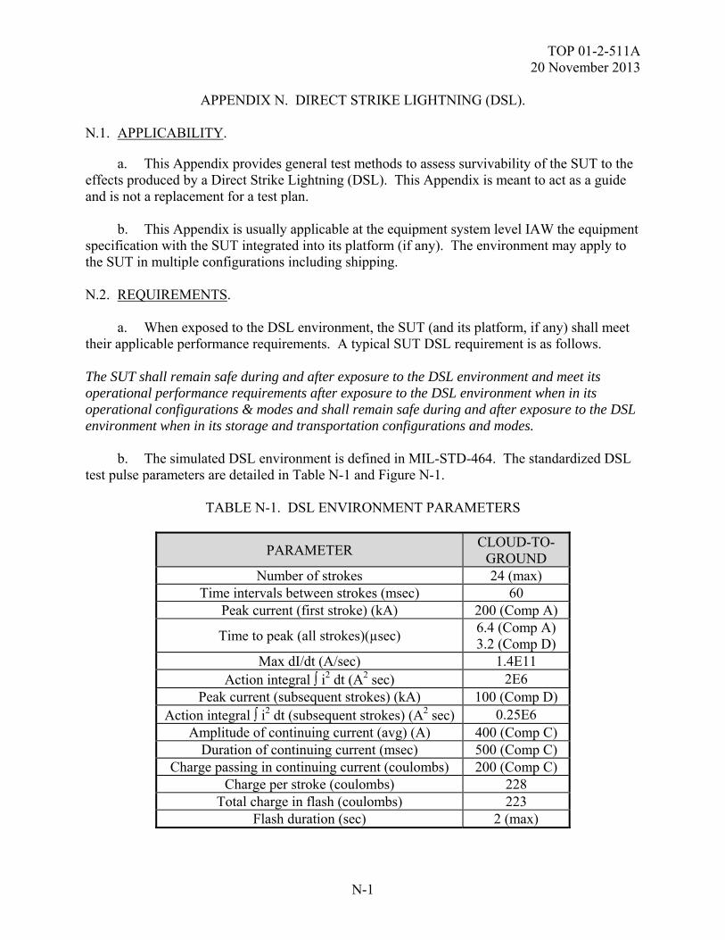
TOP 01-2-511A 20 November 2013
N-1
APPENDIX N. DIRECT STRIKE LIGHTNING (DSL). N.1. APPLICABILITY.
a. This Appendix provides general test methods to assess survivability of the SUT to the effects produced by a Direct Strike Lightning (DSL). This Appendix is meant to act as a guide and is not a replacement for a test plan. b. This Appendix is usually applicable at the equipment system level IAW the equipment specification with the SUT integrated into its platform (if any). The environment may apply to the SUT in multiple configurations including shipping. N.2. REQUIREMENTS. a. When exposed to the DSL environment, the SUT (and its platform, if any) shall meet their applicable performance requirements. A typical SUT DSL requirement is as follows. The SUT shall remain safe during and after exposure to the DSL environment and meet its operational performance requirements after exposure to the DSL environment when in its operational configurations & modes and shall remain safe during and after exposure to the DSL environment when in its storage and transportation configurations and modes. b. The simulated DSL environment is defined in MIL-STD-464. The standardized DSL test pulse parameters are detailed in Table N-1 and Figure N-1.
TABLE N-1. DSL ENVIRONMENT PARAMETERS
PARAMETER CLOUD-TO-
GROUND Number of strokes 24 (max)
Time intervals between strokes (msec) 60 Peak current (first stroke) (kA) 200 (Comp A)
Time to peak (all strokes)(µsec) 6.4 (Comp A) 3.2 (Comp D)
Max dI/dt (A/sec) 1.4E11 Action integral i2 dt (A2 sec) 2E6
Peak current (subsequent strokes) (kA) 100 (Comp D) Action integral i2 dt (subsequent strokes) (A2 sec) 0.25E6
Amplitude of continuing current (avg) (A) 400 (Comp C) Duration of continuing current (msec) 500 (Comp C)
Charge passing in continuing current (coulombs) 200 (Comp C) Charge per stroke (coulombs) 228
Total charge in flash (coulombs) 223 Flash duration (sec) 2 (max)
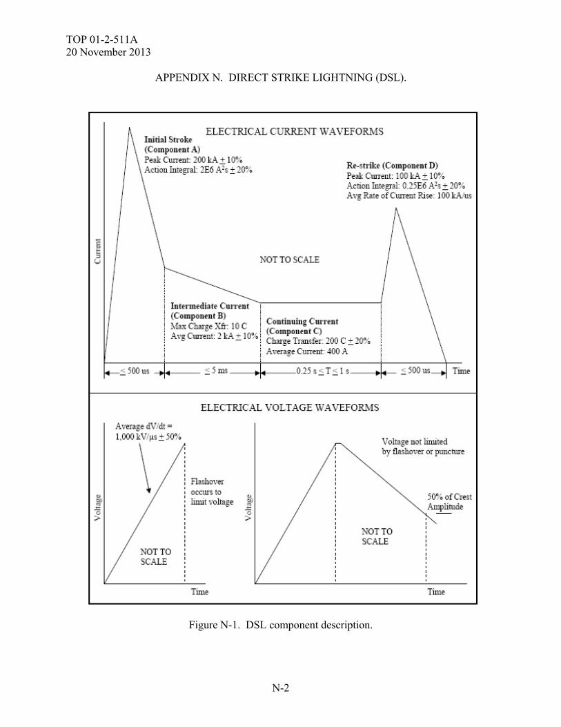
TOP 01-2-511A 20 November 2013
N-2
APPENDIX N. DIRECT STRIKE LIGHTNING (DSL).
Figure N-1. DSL component description.
TOP 01-2-511A 20 November 2013
N-3
APPENDIX N. DIRECT STRIKE LIGHTNING (DSL). c. When the SUT contains ordnance or safety critical circuits / functions (e.g. EIDs,), the SUT ordnance and safety critical circuits / functions shall meet the safety margin requirements during and after exposure to the DSL specification environment. The SUT EIDs, if any, will be considered to have passed when subjected to the DSL environment, if they exhibit sufficient safety margins. There are two classifications of EID situations, safety and reliability. In accordance with MIL-STD-464, safety (hazardous) EIDs shall maintain a 16.5 dB safety factor below the Maximum No Fire parameter (MNF) (based on not exceeding 15% of the EID MNF) and reliability (non-hazardous) EIDs shall maintain a 6 dB safety factor below the MNF (based on not exceeding 50% of the MNF). When empirical MNFE for a specific, qualified, one-Watt no-fire EID is lacking, the Army may use a level of 17.6 mJ based on previous testing of a series of Stinger launch/flight motor EIDs providing the safety factor is necessary, and when the methodology is approved by the Army E3 Board. MIL-STD-1316 specifies a minimum firing voltage of 500 volts for an ESAD. In some cases, EIDs are tested live with no instrumentation; GO-NO-GO. A JOTP is in process and should be used for guidance of joint munition ESD and Lightning testing. Testing in a tactical full up live configuration also applies as part of the JOTP for specific ordnance configurations. N.3. PURPOSE. The purpose of this testing is to verify the ability of the SUT to withstand the DSL environment IAW its specification performance requirements detailed in the test plan. A typical test purpose follows: The purpose of DSL testing is to demonstrate that the SUT remains safe and meets its operational performance requirements during and after being subjected to the DSL environment when in a stored configuration and that the SUT remains safe during and after being subjected to the DSL environment when in an operational condition. N.4. TEST SETUP. N.4.1 Test Equipment. a. A listing of the typical equipment used during DSL testing is provided in Table N-2. The test report shall include the actual test equipment used along with their serial numbers and calibration dates, if applicable. b. The test measurement equipment is required to operate in the DSL environment frequency range (dc to 2 MHz) as a minimum.
TOP 01-2-511A 20 November 2013
N-4
APPENDIX N. DIRECT STRIKE LIGHTNING (DSL).
TABLE N-2. DSL TYPICAL TEST EQUIPMENT LIST
HARDWARE DESCRIPTION
DSL Generator / Simulator
Often a custom, in-house design and build Marx generator type design, usually in four parts to simulate each of the four DSL components
HV DC Power Supply
High Voltage power supply used to charge up capacitor charge storage bank
Voltage Divider Network
Used to measure charge voltage
Down Conductor (discharge probe)
Current Probe Used to measure injection current Placed around down conductor
Current Probe Used to measure current coupled to SUT or SUT EIDs (preferred – a closed type current probe - requires a break in the line being monitored to attach the probe)
Current Probe Used to measure current coupled to SUT cable (a clamp type probe - used only when the wire cannot be cut) Need several in different physical sizes and current handling capabilities
Differential Voltage Probe
Used to measure voltage across the ESAF capacitor. Need several in different physical sizes and current handling capabilities
Field Probe E and H field probes real time field calibration and monitoring
Telemetry Unit Takes input from probes & drives fiber optic output Need several in different physical sizes and current/voltage handling capabilities
Fiber Optic Converter
Converts telemetry fiber optic signal back to an analog signal for input to oscilloscope
Fiber Optic lines To send the sensor data back to the data acquisition units Digital Storage Oscilloscope
Used to record and display current and voltage measurements Must operate in the dc to 2 MHz range minimum, Typical setting: 2 µs/div
Portable Computer
For data reduction (e.g. calculates safety margins, creates plots from data for display, stores data)
Lightning Test Software
For data reduction / presentation
Plotter To plot out data Printer c. Unless otherwise stated, test equipment tolerances shall meet the following minimum requirements:
TOP 01-2-511A 20 November 2013
N-5
APPENDIX N. DIRECT STRIKE LIGHTNING (DSL). (1) Distance: + 5 % (2) Frequency: + 2 % (3) Amplitude, measurement receiver: + 2 dB (4) Amplitude, measurement system (receiver, cables, etc): + 3 dB (5) Time (waveforms): + 5 % (6) Resistors: + 5 % (7) Capacitors: + 20 % d. Test software used, including measurement system software, SUT software, instrumentation and test set software shall be documented as to dates, developer, version number, etc. N.4.2 Instrumentation. SUT instrumentation is permissible but it shall not influence test results. To minimize the possibility of instrumentation influencing test results or instrumentation susceptibility: a. Use fiber-optic based instrumentation whenever possible. b. Use twisted, shielded pair wiring when conductive leads are required. c. Instrumentation equipment and its leads should be buried inside the SUT with only the fiber optic leads exiting the SUT. N.4.3 Instrumentation may include the following: a. Current probes to measure the stimulus current waveforms to determine the adequacy of the simulated DSL environment. b. Cameras connected to monitors in a shielded instrumentation room using fiber optic lines. The cameras may be placed within shielded enclosures. c. Test sets may be used to check out the SUT before and after each test event but should be removed from the test setup for DSL testing (if not used during the test event). If required during testing, test sets should be protected from the test environment and placed as far away from the strike point as possible. Any test set interface cabling should be well shielded and run radially away from the strike point to minimize coupling.
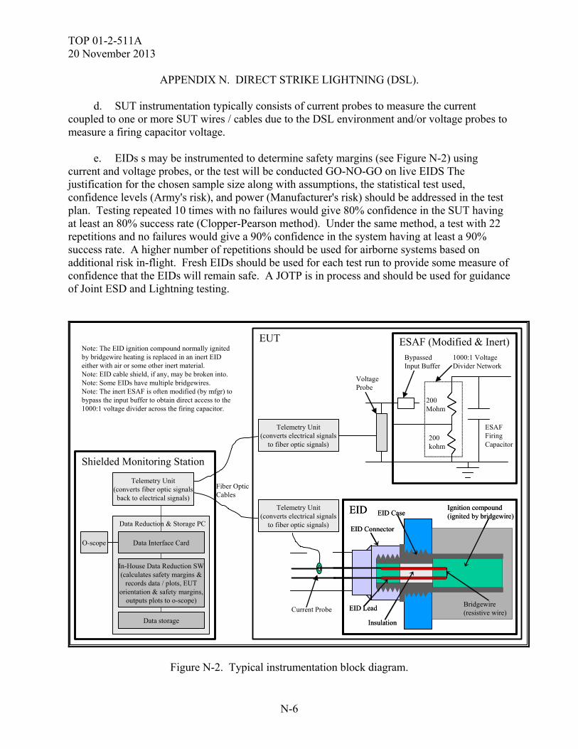
TOP 01-2-511A 20 November 2013
N-6
APPENDIX N. DIRECT STRIKE LIGHTNING (DSL). d. SUT instrumentation typically consists of current probes to measure the current coupled to one or more SUT wires / cables due to the DSL environment and/or voltage probes to measure a firing capacitor voltage. e. EIDs s may be instrumented to determine safety margins (see Figure N-2) using current and voltage probes, or the test will be conducted GO-NO-GO on live EIDS The justification for the chosen sample size along with assumptions, the statistical test used, confidence levels (Army's risk), and power (Manufacturer's risk) should be addressed in the test plan. Testing repeated 10 times with no failures would give 80% confidence in the SUT having at least an 80% success rate (Clopper-Pearson method). Under the same method, a test with 22 repetitions and no failures would give a 90% confidence in the system having at least a 90% success rate. A higher number of repetitions should be used for airborne systems based on additional risk in-flight. Fresh EIDs should be used for each test run to provide some measure of confidence that the EIDs will remain safe. A JOTP is in process and should be used for guidance of Joint ESD and Lightning testing.
Shielded Monitoring Station
Fiber OpticCables
Data Reduction & Storage PC
Data Interface Card
In-House Data Reduction SW(calculates safety margins &
records data / plots, EUTorientation & safety margins,
outputs plots to o-scope)
Data storage
Note: The EID ignition compound normally ignitedby bridgewire heating is replaced in an inert EIDeither with air or some other inert material.Note: EID cable shield, if any, may be broken into.Note: Some EIDs have multiple bridgewires.Note: The inert ESAF is often modified (by mfgr) tobypass the input buffer to obtain direct access to the1000:1 voltage divider across the firing capacitor.
EID
Bridgewire(resistive wire)
EID Connector
Insulation
EID Lead
EID CaseIgnition compound(ignited by bridgewire)
EID
Bridgewire(resistive wire)
EID Connector
Insulation
EID Lead
EID CaseIgnition compound(ignited by bridgewire)
ESAF (Modified & Inert)
ESAFFiringCapacitor
BypassedInput Buffer
200Mohm
200kohm
1000:1 VoltageDivider Network
Current Probe
VoltageProbe
Telemetry Unit(converts electrical signals
to fiber optic signals)
Telemetry Unit(converts electrical signals
to fiber optic signals)
EUT
O-scope
Telemetry Unit(converts fiber optic signalsback to electrical signals)
Figure N-2. Typical instrumentation block diagram.
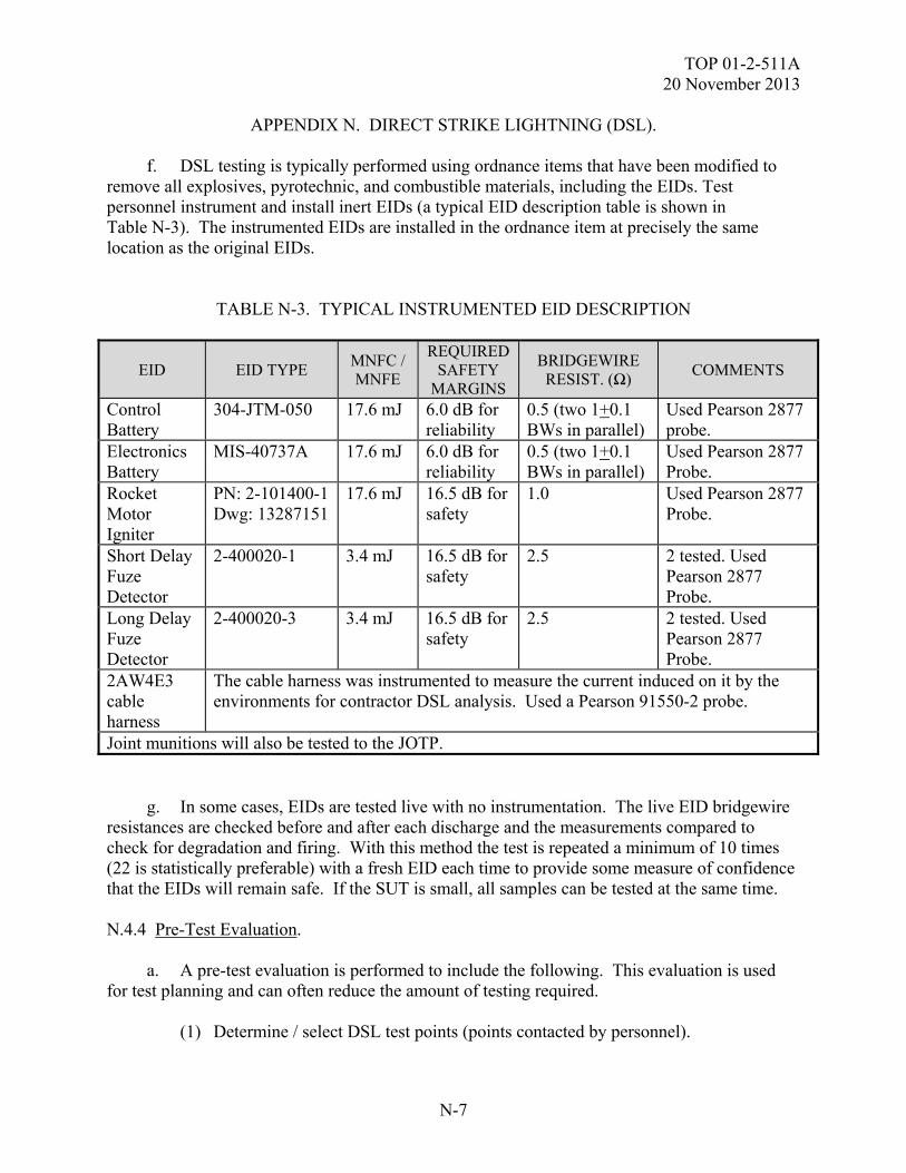
TOP 01-2-511A 20 November 2013
N-7
APPENDIX N. DIRECT STRIKE LIGHTNING (DSL). f. DSL testing is typically performed using ordnance items that have been modified to remove all explosives, pyrotechnic, and combustible materials, including the EIDs. Test personnel instrument and install inert EIDs (a typical EID description table is shown in Table N-3). The instrumented EIDs are installed in the ordnance item at precisely the same location as the original EIDs.
TABLE N-3. TYPICAL INSTRUMENTED EID DESCRIPTION
EID EID TYPE MNFC / MNFE
REQUIRED SAFETY
MARGINS
BRIDGEWIRE RESIST. (Ω)
COMMENTS
Control Battery
304-JTM-050 17.6 mJ 6.0 dB for reliability
0.5 (two 1+0.1 BWs in parallel)
Used Pearson 2877 probe.
Electronics Battery
MIS-40737A 17.6 mJ 6.0 dB for reliability
0.5 (two 1+0.1 BWs in parallel)
Used Pearson 2877 Probe.
Rocket Motor Igniter
PN: 2-101400-1 Dwg: 13287151
17.6 mJ 16.5 dB for safety
1.0 Used Pearson 2877 Probe.
Short Delay Fuze Detector
2-400020-1 3.4 mJ 16.5 dB for safety
2.5 2 tested. Used Pearson 2877 Probe.
Long Delay Fuze Detector
2-400020-3 3.4 mJ 16.5 dB for safety
2.5 2 tested. Used Pearson 2877 Probe.
2AW4E3 cable harness
The cable harness was instrumented to measure the current induced on it by the environments for contractor DSL analysis. Used a Pearson 91550-2 probe.
Joint munitions will also be tested to the JOTP. g. In some cases, EIDs are tested live with no instrumentation. The live EID bridgewire resistances are checked before and after each discharge and the measurements compared to check for degradation and firing. With this method the test is repeated a minimum of 10 times (22 is statistically preferable) with a fresh EID each time to provide some measure of confidence that the EIDs will remain safe. If the SUT is small, all samples can be tested at the same time. N.4.4 Pre-Test Evaluation. a. A pre-test evaluation is performed to include the following. This evaluation is used for test planning and can often reduce the amount of testing required. (1) Determine / select DSL test points (points contacted by personnel).
TOP 01-2-511A 20 November 2013
N-8
APPENDIX N. DIRECT STRIKE LIGHTNING (DSL). (2) Determine the primary DSL current paths. (3) Determine the most / least susceptible SUT configurations. (4) Determine the most / least susceptible SUT modes of operation. (5) Determine the probable Ports of Entry (POEs). (6) Determine the bulk current measurement points. (7) Perform an energy coupling analysis to identify the type and capability requirements for the data acquisition system. Usually, clamp-on non-obtrusive current probes are used to not affect the inherent shielding integrity of the cable or the SUT shielding integrity. (8) Determine critical SUT data required to be instrumented and monitored. (9) Determine which EIDs are to be instrumented, monitored, measured and how. (10) Determine SUT/platform critical functions and circuits. (11) Determine SUT DSL protection features and their predicted performance and whether they are repairable or replaceable. (12) Determine verification and pass/fail criteria and required safety margins. (13) Determine the SUT operating and check-out procedures. b. Pre-existing analyses and test data from previous tests may be evaluated and incorporated into the test planning and pre-test analysis in order to enhance and reduce the scope of the new testing. N.4.5 Setup. Test setups vary. Some typical test setups and photographs are shown in Figures N-3 through N-7. Following are general / typical test setup guidelines. a. The DSL environment is generated by discharging the energy in several capacitor banks through low resistance cables onto the SUT attachment points. The different capacitor banks are set up to produce different components of the lightning waveform (A through D). The SUT / platform will be grounded to the return side of the lightning generator. The return path should be less than 1.0 Ω resistance and less than 20 µH of inductance.
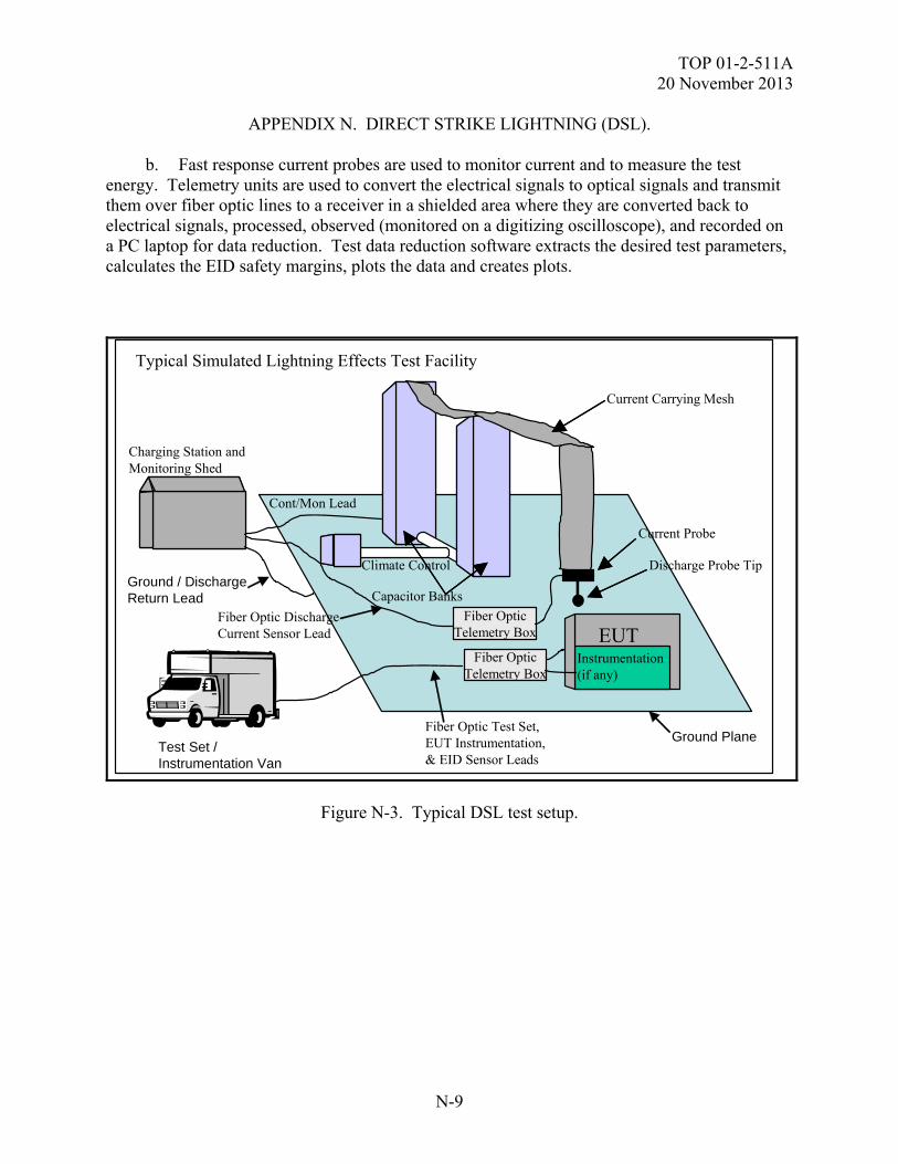
TOP 01-2-511A 20 November 2013
N-9
APPENDIX N. DIRECT STRIKE LIGHTNING (DSL). b. Fast response current probes are used to monitor current and to measure the test energy. Telemetry units are used to convert the electrical signals to optical signals and transmit them over fiber optic lines to a receiver in a shielded area where they are converted back to electrical signals, processed, observed (monitored on a digitizing oscilloscope), and recorded on a PC laptop for data reduction. Test data reduction software extracts the desired test parameters, calculates the EID safety margins, plots the data and creates plots.
Charging Station andMonitoring Shed
Climate Control Discharge Probe Tip
Capacitor Banks
Current Carrying Mesh
Current Probe
Instrumentation(if any)
EUT
Cont/Mon Lead
Fiber Optic DischargeCurrent Sensor Lead
Typical Simulated Lightning Effects Test Facility
Fiber Optic Test Set,EUT Instrumentation,& EID Sensor Leads
Test Set / Instrumentation Van
Ground Plane
Ground / DischargeReturn Lead
Fiber OpticTelemetry Box
Fiber OpticTelemetry Box
Figure N-3. Typical DSL test setup.
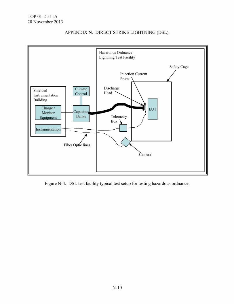
TOP 01-2-511A 20 November 2013
N-10
APPENDIX N. DIRECT STRIKE LIGHTNING (DSL).
EUT
Safety Cage
CapacitorBanks
ClimateControl
ShieldedInstrumentationBuilding
TelemetryBox
Camera
Hazardous OrdnanceLightning Test Facility
Charge /Monitor
Equipment
Instrumentation
Fiber Optic lines
Injection CurrentProbe
DischargeHead
Figure N-4. DSL test facility typical test setup for testing hazardous ordnance.
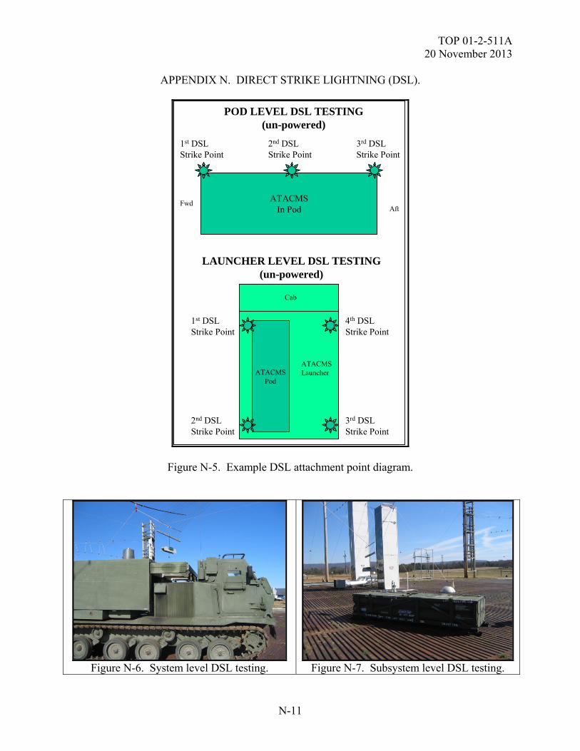
TOP 01-2-511A 20 November 2013
N-11
APPENDIX N. DIRECT STRIKE LIGHTNING (DSL).
ATACMSIn Pod
2nd DSLStrike Point
3rd DSLStrike Point
1st DSLStrike Point
2nd DSLStrike Point
3rd DSLStrike Point
1st DSLStrike Point
AftFwd
4th DSLStrike Point
ATACMSPod
Cab
ATACMSLauncher
POD LEVEL DSL TESTING(un-powered)
LAUNCHER LEVEL DSL TESTING(un-powered)
Figure N-5. Example DSL attachment point diagram.
Figure N-6. System level DSL testing. Figure N-7. Subsystem level DSL testing.
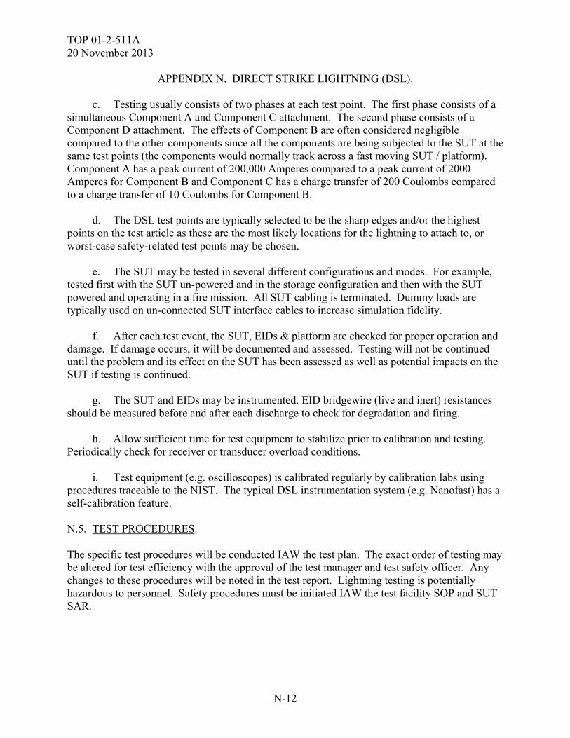
TOP 01-2-511A 20 November 2013
N-12
APPENDIX N. DIRECT STRIKE LIGHTNING (DSL). c. Testing usually consists of two phases at each test point. The first phase consists of a simultaneous Component A and Component C attachment. The second phase consists of a Component D attachment. The effects of Component B are often considered negligible compared to the other components since all the components are being subjected to the SUT at the same test points (the components would normally track across a fast moving SUT / platform). Component A has a peak current of 200,000 Amperes compared to a peak current of 2000 Amperes for Component B and Component C has a charge transfer of 200 Coulombs compared to a charge transfer of 10 Coulombs for Component B. d. The DSL test points are typically selected to be the sharp edges and/or the highest points on the test article as these are the most likely locations for the lightning to attach to, or worst-case safety-related test points may be chosen. e. The SUT may be tested in several different configurations and modes. For example, tested first with the SUT un-powered and in the storage configuration and then with the SUT powered and operating in a fire mission. All SUT cabling is terminated. Dummy loads are typically used on un-connected SUT interface cables to increase simulation fidelity. f. After each test event, the SUT, EIDs & platform are checked for proper operation and damage. If damage occurs, it will be documented and assessed. Testing will not be continued until the problem and its effect on the SUT has been assessed as well as potential impacts on the SUT if testing is continued. g. The SUT and EIDs may be instrumented. EID bridgewire (live and inert) resistances should be measured before and after each discharge to check for degradation and firing. h. Allow sufficient time for test equipment to stabilize prior to calibration and testing. Periodically check for receiver or transducer overload conditions. i. Test equipment (e.g. oscilloscopes) is calibrated regularly by calibration labs using procedures traceable to the NIST. The typical DSL instrumentation system (e.g. Nanofast) has a self-calibration feature. N.5. TEST PROCEDURES. The specific test procedures will be conducted IAW the test plan. The exact order of testing may be altered for test efficiency with the approval of the test manager and test safety officer. Any changes to these procedures will be noted in the test report. Lightning testing is potentially hazardous to personnel. Safety procedures must be initiated IAW the test facility SOP and SUT SAR.
TOP 01-2-511A 20 November 2013
N-13
APPENDIX N. DIRECT STRIKE LIGHTNING (DSL). N.5.1 Calibration. a. Test Equipment Calibration: Calibration of the test equipment shall be traceable to the NIST. b. DSL Test Setup Calibration (to confirm proper operation of the instrumentation and capacitor banks and to verify specification waveform parameters): (1) Set up the DSL simulator and discharge head IAW Figure N.3-1 without the SUT being in the setup. (2) Place the current probe around the lightning simulator discharge conductor to measure the stroke current amplitude and waveform. (3) Connect the current probe to the data collection system (oscilloscope and PC) through the telemetry system and fiber optic cables. (4) Set the DSL simulator equipment to settings that past experience has shown to discharge per the specification waveform parameters. (5) Secure the test area and insure that personnel are at a safe distance. (6) Charge up Component A and C capacitor banks and discharge to the return. (7) Repeat, adjusting the DSL simulator until the DSL criteria is obtained. (8) Record the DSL simulator calibration settings. (9) Verify DSL simulator is in a safe configuration. (10) Repeat for each DSL component, as necessary. N.5.2 EID Instrumentation Calibration. a. Check instrumentation operation for the SUT, EIDs, ESAFs, etc. b. Test EIDs and their associated firing circuit continuity and operation. c. Exercise instrumentation self-calibration features, if available.
TOP 01-2-511A 20 November 2013
N-14
APPENDIX N. DIRECT STRIKE LIGHTNING (DSL). N.5.3 Test. a. Set up the SUT for DSL testing IAW Figure N.3 using the same test equipment and settings used during calibration. Set up the instrumentation equipment (e.g. to monitor EID current / energy coupling), if applicable. b. Connect the instrumentation (e.g. current probes) to the data collection system (oscilloscope and PC) using the telemetry system and fiber optic cables. If required, set up a camera to monitor the discharge. (1) Set up the DSL simulator downlink at a selected SUT attachment point IAW the test plan matrix. Place a current probe around the lightning simulator downlink conductor to measure the stroke current amplitude and waveform. (2) Power up the SUT and run a pre-test baseline functional check. (3) Place the SUT in a test plan matrix specified configuration and mode. (4) Verify data acquisition and instrumentation equipment operation. (5) Secure the test area and insure that personnel are at a safe distance. (6) Charge up the capacitor banks and discharge them to an SUT attachment point using the calibration settings. (7) Verify that the lightning generator is in a safe configuration. (8) After each discharge, examine the data to ensure that the DSL criteria were simulated, the test data is adequate, and the data is within pass/fail criteria. (9) After each discharge, perform a visual check of the SUT for any lightning induced damage. (10) After each discharge, repeat SUT operational checks and compare to baseline. (11) If there are any susceptibilities, determine the SUT components affected the required steps to recovery (e.g. cycling power) and the recovery time. If possible (if SUT not damaged), verify the repeatability of the susceptibility and determine the threshold and safety margins, if necessary. c. Record the following for each discharge and mark on plots. (1) Stimulus waveform parameter data / plots.
TOP 01-2-511A 20 November 2013
N-15
APPENDIX N. DIRECT STRIKE LIGHTNING (DSL). (2) Test configuration / test mode. (3) Test discharge point. (4) Post-discharge functional check pass/fail results. (5) Visual damage inspection results. (6) SUT responses (e.g. components affected, wire/cable currents, EID currents, SUT upsets, recovery times, etc.). (7) EIDs monitored their calculated SMs and whether they met requirements. (8) EID bridgewire resistance and determination of degradation, if required. (9) Date, time, location. d. Repeat the test procedure for each lighting attachment point and DSL component, as necessary. e. Repeat the test procedure for all test modes and configurations. N.6. DATA PRESENTATION. Sample data sheets are provided in Tables N-3 and N-4. Note: data should be reported at the level of accuracy of the test equipment. Sample test photographs and test data plots are provided in Figures N-8 through N-13.
TABLE N-3. EXAMPLE DSL TEST RUN DATA SHEET – TEST WITHOUT SUT INSTRUMENTATION
TEST CONFIG
TEST MODE
DISCHARGE LOCATION
SHOT #
TEST PULSE PARAMETERS
OBSERVED DAMAGE / RESPONSE FUNCTIONAL CHECK RESULTS
PASS / FAIL
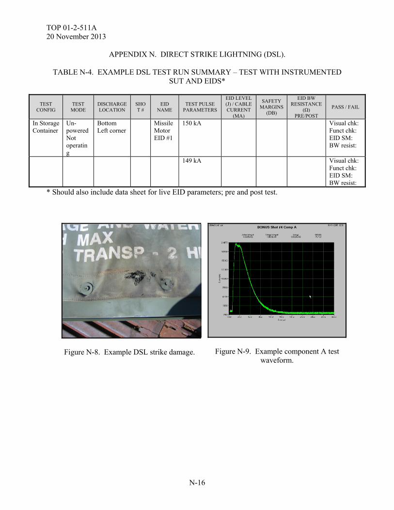
TOP 01-2-511A 20 November 2013
N-16
APPENDIX N. DIRECT STRIKE LIGHTNING (DSL).
TABLE N-4. EXAMPLE DSL TEST RUN SUMMARY – TEST WITH INSTRUMENTED SUT AND EIDS*
TEST CONFIG
TEST MODE
DISCHARGE LOCATION
SHOT #
EID NAME
TEST PULSE PARAMETERS
EID LEVEL (J) / CABLE CURRENT
(MA)
SAFETY MARGINS
(DB)
EID BW RESISTANCE
(Ω) PRE/POST
PASS / FAIL
In Storage Container
Un-powered Not operating
Bottom Left corner
Missile Motor EID #1
150 kA Visual chk: Funct chk: EID SM: BW resist:
149 kA Visual chk: Funct chk: EID SM: BW resist:
* Should also include data sheet for live EID parameters; pre and post test.
Figure N-8. Example DSL strike damage.
Figure N-9. Example component A test waveform.
TOP 01-2-511A 20 November 2013
N-17
APPENDIX N. DIRECT STRIKE LIGHTNING (DSL).
Figure N-10. Example component C test
waveform.
Figure N-11. Example component D test
waveform.
Figure N-12. Example cable current data
plot.
Figure N-13. Example EID current data plot.
N.7. DATA ANALYSIS.
a. Test data will be compared and evaluated against the criteria set forth in MIL-STD 464, the SUT specification, and SUT test plan to determine if the SUT met the criteria. Deficiencies will be identified and discussed.
TOP 01-2-511A 20 November 2013
N-18
APPENDIX N. DIRECT STRIKE LIGHTNING (DSL). b. The safety margins are calculated using the following formulas: ENERGY: SM (dB) = 10 log10 (EMNF / EInduced) where EMNF = Max No-Fire energy of EID. Typically 17.6 milli-Joules1 Einduced = measured energy induced in the EID circuit (J) CURRENT: SM (dB) = 20 log10 (IMNF / IInduced) where IMNF = Maximum No-Fire current of EID (A) Iinduced = measured value for the induced EID current (A) (or Minimum Discernible Current, MDC, if signal below MDC) VOLTAGE: SM (dB) = 20 log10 (MFV / VInduced) where MFV = Min ESAD capacitor Firing Voltage. Typically 500 Volts2 Vinduced = measured value for the induced ESAD cap firing voltage (or Minimum Discernible Voltage, MDV, if signal below MDV)
NOTE (1) - Previous test programs have used 17.6 milli-Joules as the MNFE for safety margin calculations for MIL-I 23659 qualified, one watt, no-fire initiators. The MNFE value was established during testing of a series of Stinger Launch/Flight motor EIDs. The EID testing evaluated 72 initiators tested with a one amp per millisecond current ramp. The data was used to derive the MNFE and is documented in technical document RD-TE-87-4, MLRS AT2 Lightning Test Report. NOTE (2) - MIL-STD-1316 requirement for minimum firing voltage = 500 volts. Most initiators have minimum firing voltages in the 1000 to 2000 volt range. NOTE (3) - or the test will be conducted GO-NO-GO on live EIDS. A Joint Service E3 Safety Testing procedure is in process and should be used for guidance in testing of Joint munitions to HERO, EMP, ESD and Lightning. or live tactical ordnance as specified in applicable requirement documents. The DSL environmental data may require extrapolation to the 200 kA level. If the test discharge current level available during the test is less than the criteria, then the measured (DSL induced) current, voltage or energy will be extrapolated analytically to the required criteria. The extrapolation expressions are defined as follows:

TOP 01-2-511A 20 November 2013
N-19
APPENDIX N. DIRECT STRIKE LIGHTNING (DSL). ENERGY: Eextrapolated = Einduced (Icriteria / Itest)
2 Where Eextrapolated = the extrapolated value of the induced energy (J) The extrapolated value for energy can then used in place of the measured induced energy value to calculate the safety margin or the following expression can be used:
SMextrapolated (dB) = 10 log10 (EMNF / Einduced) × K Where K = (Icriteria / Itest)
2 CURRENT: Iextrapolated = Iinduced (Icriteria / Itest) Where Iextrapolated = the extrapolated value of the induced current (A) Icriteria = the required (criteria) discharge current (A) (Table C.2-1) Itest = the actual discharge current amplitude measured during the test (A) The extrapolated value for current can then used in place of the measured induced current value to calculate the safety margin or the following expression can be used:
SMextrapolated (dB) = 20 log10 (IMNF / Iinduced) × K Where K = (Icriteria / Itest) < 1 VOLTAGE: Vextrapolated = Vinduced (Icriteria / Itest) Where Vextrapolated = the extrapolated value of the induced voltage (V) The extrapolated value for voltage can then used in place of the measured induced voltage value to calculate the safety margin or the following expression can be used:
SMextrapolated (dB) = 20 log10 (MFV / Vinduced) × K Where K = (Icriteria / Itest) < 1 c. The test data will be compared to the applicable criteria set forth in MIL-STD 464C, the SUT specification, and SUT test plan and the pre-event baseline measurements to determine the extent to which the test criteria are met and the effects of the DSL test environment on the SUT. Test anomalies will be assessed to determine if they should be classified as SUT failures and if so, further assessed with regards to causes, test parameters at which they occurred, mission impact and safety. Safety margins will be calculated and compared to the criteria, as necessary.

TOP 01-2-511A 20 November 2013
N-20
(This page is intentionally blank.)
TOP 01-2-511A 20 November 2013
O-1
APPENDIX O. ABBREVIATIONS. AAE Army Acquisition Executive ADS Aeronautical Design Standard AEC US Army Evaluation Center AM amplitude modulation ANSI American National Standards Institute ASTM American Society for Testing and Materials ATEC US Army Test and Evaluation Command ATPD Army-Tank Purchase Description BER bit error rate BFACS Battlefield Functional Area Control System BFT Blue Force Tracker BIT built-in test BITE built-in test equipment CNNS Committee on National Security Systems COTS commercial off-the shelf CTTA Certified TEMPEST Technical Authority CW continuous wave DAS data acquisition system dB decibel dBm decibel referenced to milliwatt DC direct current DIACAP Defense Information Assurance Certification and Accreditation
Process DOD Department of Defense DODD Department of Defense Directive DODI Department of Defense Instruction DSL direct strike lightning E3 electromagnetic environmental effects EED electro explosive device E field electromagnetic field EFI exploding foil initiator EID electrically initiated device EM electromagnetic EMC electromagnetic compatibility EME electromagnetic environment EMI electromagnetic interference EMICP electromagnetic interference control procedures EMITP electromagnetic interference test procedures EMITR electromagnetic interference test report
TOP 01-2-511A 20 November 2013
O-2
APPENDIX O. ABBREVIATIONS. EMNF Max No-Fire energy of EID EMP electromagnetic pulse EMR electromagnetic radiation EMRADHAZ electromagnetic radiation hazards EMRH electromagnetic radiation hazard EPLRS Enhanced Position Location and Reporting System ERP effective radiated power ESAD Electronic Safe and Arm Device ESD electrostatic discharge FI field intensity FM frequency modulation GHz Giga-hertz H Horizontal HERF hazards of electromagnetic radiation to fuel HERO hazards of electromagnetic radiation to ordnance HERP hazards of electromagnetic radiation to personnel HESD helicopter generated electrostatic discharge HEMP high altitude electromagnetic pulse H field magnetic field HPM high power microwave IAW in accordance with IEEE Institute of Electrical and Electronics Engineers IMI intermodulation interference IMNF Max No-Fire current of EID ISR intelligence, surveillance, and reconnaissance JOERAD Joint Ordnance Electromagnetic Risk Assessment Database JOTP Joint Ordnance Test Procedure kHz kilohertz km kilometer KPP key performance parameter KV kilovolt KV/m kilovolt per meter LAN local area network LE lightning effects LEFI low energy exploding foil initiator LISN line impedance stabilization network
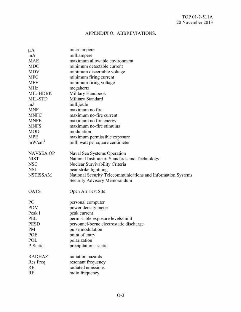
TOP 01-2-511A 20 November 2013
O-3
APPENDIX O. ABBREVIATIONS. A microampere mA milliampere MAE maximum allowable environment MDC minimum detectable current MDV minimum discernible voltage MFC minimum firing current MFV minimum firing voltage MHz megahertz MIL-HDBK Military Handbook MIL-STD Military Standard mJ millijoule MNF maximum no fire MNFC maximum no-fire current MNFE maximum no fire energy MNFS maximum no-fire stimulus MOD modulation MPE maximum permissible exposure mW/cm2 milli watt per square centimeter NAVSEA OP Naval Sea Systems Operation NIST National Institute of Standards and Technology NSC Nuclear Survivability Criteria NSL near strike lightning NSTISSAM National Security Telecommunications and Information Systems
Security Advisory Memorandum OATS Open Air Test Site PC personal computer PDM power density meter Peak I peak current PEL permissible exposure levels/limit PESD personnel-borne electrostatic discharge PM pulse modulation POE point of entry POL polarization P-Static precipitation - static RADHAZ radiation hazards Res Freq resonant frequency RE radiated emissions RF radio frequency
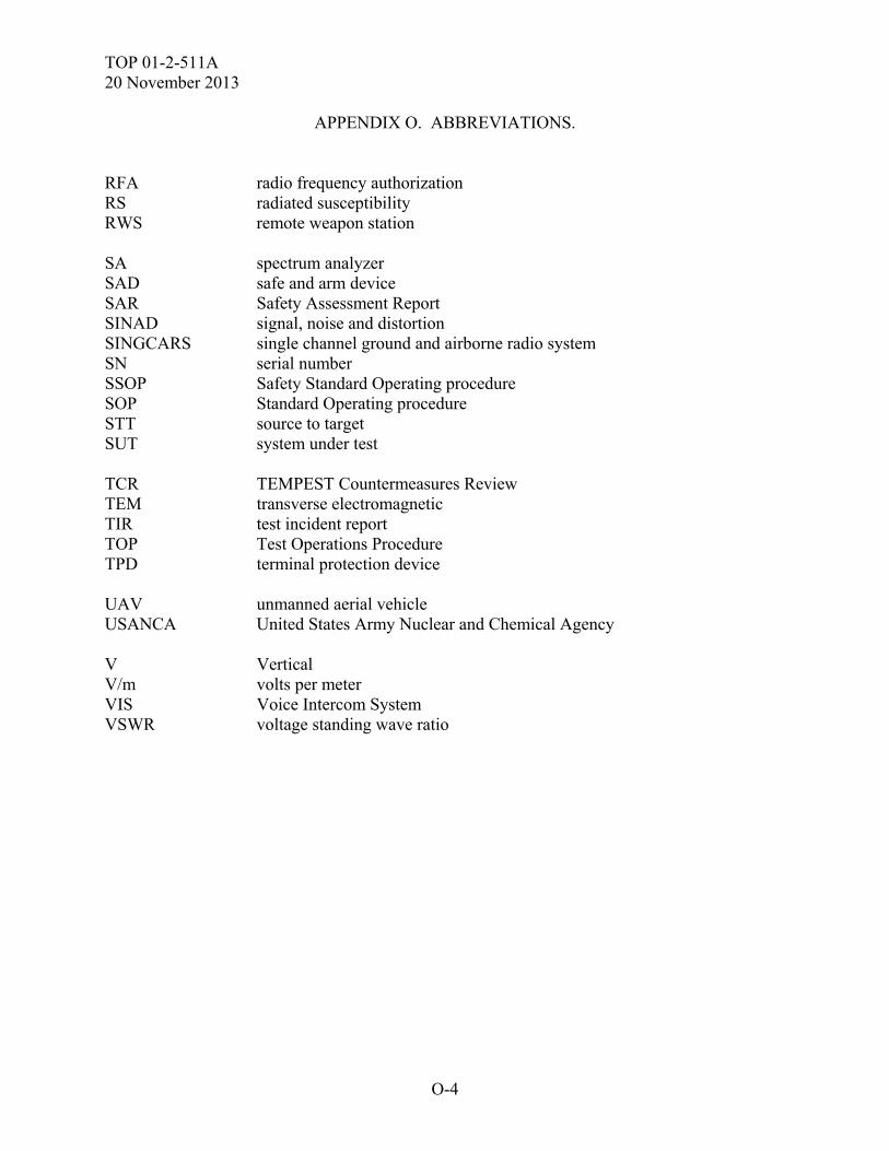
TOP 01-2-511A 20 November 2013
O-4
APPENDIX O. ABBREVIATIONS. RFA radio frequency authorization RS radiated susceptibility RWS remote weapon station SA spectrum analyzer SAD safe and arm device SAR Safety Assessment Report SINAD signal, noise and distortion SINGCARS single channel ground and airborne radio system SN serial number SSOP Safety Standard Operating procedure SOP Standard Operating procedure STT source to target SUT system under test TCR TEMPEST Countermeasures Review TEM transverse electromagnetic TIR test incident report TOP Test Operations Procedure TPD terminal protection device UAV unmanned aerial vehicle USANCA United States Army Nuclear and Chemical Agency V Vertical V/m volts per meter VIS Voice Intercom System VSWR voltage standing wave ratio
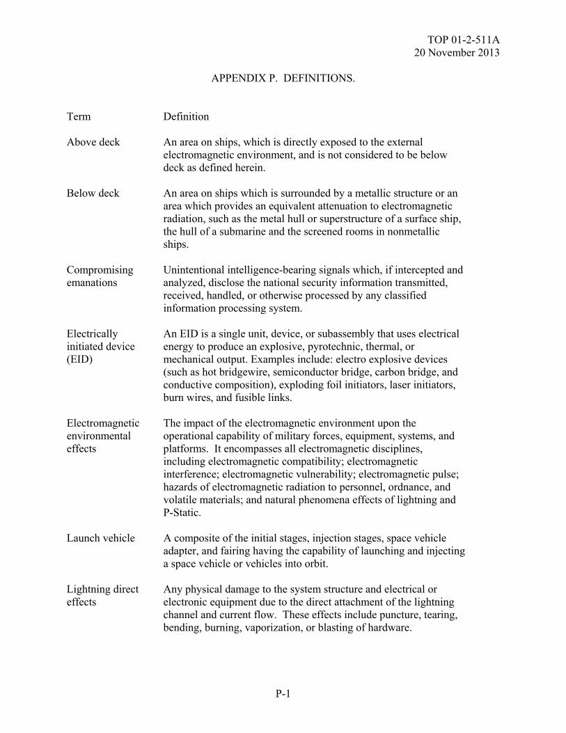
TOP 01-2-511A 20 November 2013
P-1
APPENDIX P. DEFINITIONS. Term Definition Above deck An area on ships, which is directly exposed to the external
electromagnetic environment, and is not considered to be below deck as defined herein.
Below deck An area on ships which is surrounded by a metallic structure or an
area which provides an equivalent attenuation to electromagnetic radiation, such as the metal hull or superstructure of a surface ship, the hull of a submarine and the screened rooms in nonmetallic ships.
Compromising emanations
Unintentional intelligence-bearing signals which, if intercepted and analyzed, disclose the national security information transmitted, received, handled, or otherwise processed by any classified information processing system.
Electrically initiated device (EID)
An EID is a single unit, device, or subassembly that uses electrical energy to produce an explosive, pyrotechnic, thermal, or mechanical output. Examples include: electro explosive devices (such as hot bridgewire, semiconductor bridge, carbon bridge, and conductive composition), exploding foil initiators, laser initiators, burn wires, and fusible links.
Electromagnetic environmental effects
The impact of the electromagnetic environment upon the operational capability of military forces, equipment, systems, and platforms. It encompasses all electromagnetic disciplines, including electromagnetic compatibility; electromagnetic interference; electromagnetic vulnerability; electromagnetic pulse; hazards of electromagnetic radiation to personnel, ordnance, and volatile materials; and natural phenomena effects of lightning and P-Static.
Launch vehicle A composite of the initial stages, injection stages, space vehicle
adapter, and fairing having the capability of launching and injecting a space vehicle or vehicles into orbit.
Lightning direct effects
Any physical damage to the system structure and electrical or electronic equipment due to the direct attachment of the lightning channel and current flow. These effects include puncture, tearing, bending, burning, vaporization, or blasting of hardware.
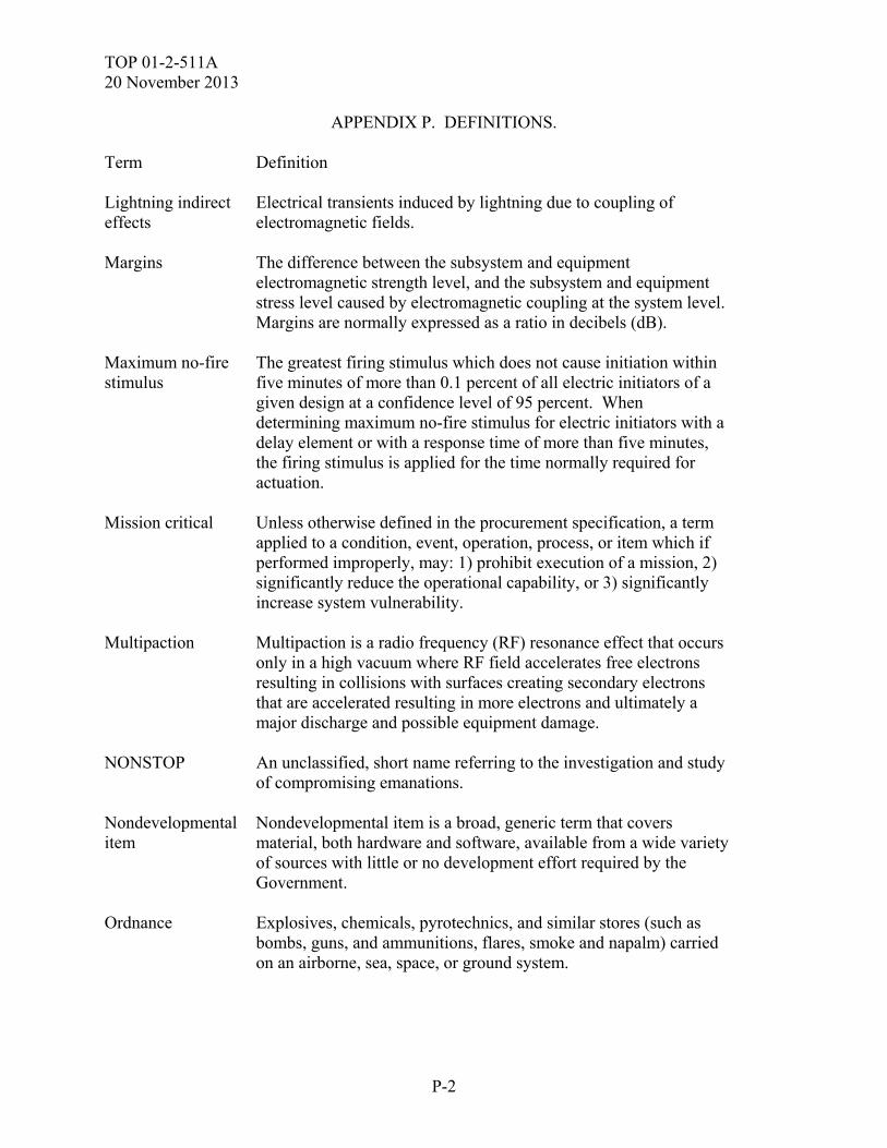
TOP 01-2-511A 20 November 2013
P-2
APPENDIX P. DEFINITIONS. Term Definition Lightning indirect effects
Electrical transients induced by lightning due to coupling of electromagnetic fields.
Margins The difference between the subsystem and equipment
electromagnetic strength level, and the subsystem and equipment stress level caused by electromagnetic coupling at the system level. Margins are normally expressed as a ratio in decibels (dB).
Maximum no-fire stimulus
The greatest firing stimulus which does not cause initiation within five minutes of more than 0.1 percent of all electric initiators of a given design at a confidence level of 95 percent. When determining maximum no-fire stimulus for electric initiators with a delay element or with a response time of more than five minutes, the firing stimulus is applied for the time normally required for actuation.
Mission critical Unless otherwise defined in the procurement specification, a term
applied to a condition, event, operation, process, or item which if performed improperly, may: 1) prohibit execution of a mission, 2) significantly reduce the operational capability, or 3) significantly increase system vulnerability.
Multipaction Multipaction is a radio frequency (RF) resonance effect that occurs
only in a high vacuum where RF field accelerates free electrons resulting in collisions with surfaces creating secondary electrons that are accelerated resulting in more electrons and ultimately a major discharge and possible equipment damage.
NONSTOP An unclassified, short name referring to the investigation and study
of compromising emanations. Nondevelopmental item
Nondevelopmental item is a broad, generic term that covers material, both hardware and software, available from a wide variety of sources with little or no development effort required by the Government.
Ordnance Explosives, chemicals, pyrotechnics, and similar stores (such as
bombs, guns, and ammunitions, flares, smoke and napalm) carried on an airborne, sea, space, or ground system.
TOP 01-2-511A 20 November 2013
P-3
APPENDIX P. DEFINITIONS. Term Definition Safety critical Unless otherwise defined in the procurement specification, a term
applied to a condition, event, operation, process, or item whose proper recognition, control, performance or tolerance is essential to safe system operation or use; for example, safety critical function, safety critical path, or safety critical component.
Space vehicle A complete, integrated set of subsystems and components capable
of supporting an operational role in space. A space vehicle may be an orbiting vehicle, a major portion of an orbiting vehicle, or a payload of an orbiting vehicle which performs its mission while attached to a recoverable launch vehicle. The airborne support equipment, which is peculiar to programs utilizing a recoverable launch vehicle, is considered a part of the space vehicle being carried by the launch vehicle.
System operational performance
A set of minimal acceptable parameters tailored to the platform and reflecting top level capabilities such as range, probability of kill, probability of survival, operational availability, and so forth. A primary aspect of acquisition related to this definition are key performance parameters (KPPs), which are used in acquisition to specify system characteristics that are considered most essential for successful mission accomplishment and that are tracked during development to evaluate the effectiveness of the system. For the purposes of this document, the set of parameters under consideration would normally extend beyond this limited set of parameters to address other details of system performance that may be less critical but still have a substantial impact on system effectiveness.
TEMPEST An unclassified, short name referring to the investigation and study
of compromising emanations.

TOP 01-2-511A 20 November 2013
P-4
(This page is intentionally blank.)
TOP 01-2-511A 20 November 2013
Q-1
APPENDIX Q. REFERENCES.
1. MIL-STD-464C, Department of Defense Interface Standard: Electromagnetic Environmental Effects Requirements for Systems, 1 December 2010.
2. ADS-37A-PRF, Aeronautical Design Standard: Electromagnetic Environmental Effects
(E3) Performance and Verification Requirements, 28 May 1996. 3. ATPD-2407, Electromagnetic Environmental Effects (E3) for US Army Tank and
Automotive Vehicle Systems Tailored From MIL-STD-464C, June 25, 2012 4. MIL-STD-461F, Department of Defense Interface Standard: Requirements for the
Control of Electromagnetic Interference Characteristics of Subsystems and Equipment, 10 December 2007.
5. MIL -STD-2169B Notice 1 (Classified), Department of Defense Interface Standard: High
Altitude Electromagnetic Pulse (HEMP) Environment, 19 January 2012. 6. ASTM E1851-09, Standard Test Method for Electromagnetic Shielding Effectiveness of
Durable Rigid Wall Relocatable Structures, 2009. 7. MIL-HDBK-235/1C, Department of Defense Handbook: Military Occupational
Electromagnetic Environment Profiles, Part 1C, General Guidance, 1 October 2010. 8. MIL-HDBK-235/4C, Department of Defense Handbook: External Electromagnetic
Environment Levels for Ground Systems, 1 October 2010. 9. MIL-HDBK-240A, Department of Defense Handbook: Hazards of Electromagnetic
Radiation to Ordnance (HERO) Test Guide, 10 March 2011. 10. JOTP-061, Joint Ordnance Test Procedure, Hazards of Electromagnetic Radiation to
Ordnance (HERO) Safety Test, 10 January 2013. 11. Army Technical Report TR-RD-TE-97-01, Electromagnetic Environmental Effects
Criteria and Guidelines for EMRH, EMRO, Lightning Effects, ESD, EMP, and EMI Testing of US Army Missile Systems.
12. DODI 6055.11, Protecting Personnel from Electromagnetic Fields, 19 August 2009. 13. IEEE C95.3-2002, IEEE Recommended Practice for Measurements and Computations of
Radio Frequency Electromagnetic Fields with Respect to Human Exposure to Such Fields, 100 kHz to 300 GHz, 2002.
14. IEEE C95.1-2005, IEEE Standard for Safety Levels with Respect to Human Exposure to
Radio Frequency Electromagnetic Fields, 3 kHz to 300 GHz, 2005.
TOP 01-2-511A 20 November 2013
Q-2
APPENDIX Q. REFERENCES. 15. MIL-STD-1316E, Department of Defense Design Criteria Standard; Fuze Design, Safety
Criteria For, 10 July 1998. 16. MIL-DTL-23659E, Detail Specification; Initiators, Electric, General Design
Specification For, 27 September 2007. 17. RD-TE-87-4, MLRS AT2 Lightning Test Report. 18. NAVSEA OP 3565 Volume 1, Revision 6, Electromagnetic Radiation Hazards to
Personnel Fuel and Other Flammable Material, 20 August 2012. 19. NSTISSAM Compromising Emanations Laboratory Test TEMPEST/1-92 Requirements,
Electromagnetic. 20. CNSS Advisory Memorandum, NONSTOP Evaluation Standard TEMPEST 01-02,
October 2002. 21. DODD 5200.19, Control of Compromising Emanations, 16 May 1995. 22. NSTISSAM Compromising Emanations Field Test TEMPEST/1-93 Requirements,
Electomagnetics. 23. NSTISSAM Red/Black Installation Guidance TEMPEST/2-95. 24. Navy IA Pub 5239-31, Information Assurance Shipboard Red/Black Installation
Publication, July 2001. 25. NSTISSAM Compromising Emanations Analysis Handbook TEMPEST/2-91. 26. NSTISSAM Advisory Memorandum for the Strategy for Using the National Information
Assurance Partnership (NIAP) for the Evaluation of Commercial Off-The Shelf (COTS) Security Enabled Information Technology Products TEMPEST/2-00.
27. KAG-30 ()/TSEC, Compromising Emanations Standard for Cryptographic Equipment. 28. NSTISSAM Rationale for Compromising Emanations Laboratory and Field Test
Requirements, Electromagnetic TEMPEST/2-93. 29. MIL-STD-461E, Department of Defense Interface Standard: Requirements for the
Control of Electromagnetic Interference Characteristics of Subsystems and Equipment, 20 August 1999.

TOP 01-2-511A 20 November 2013
Q-3
APPENDIX Q. REFERENCES.
For information only (related publications).
a. MIL-STD-1399/070Part 1, Military Standard: Interface Standard for Shipboard Systems (Section 070-Part 1) D.C. Magnetic Field Environment, 26 February 1979.
b. DODD 4650.1, Policy and Procedures for Management and Use of the Electromagnetic
Spectrum, 9 January 2009. d. NTIA Manual of Regulations and Procedures for Federal Radio Frequency Management. e. MIL-STD-331C with Change 1, Department of Defense Test Method Standard: Fuze and
Fuze Components, Environmental and Performance Tests For, 22 June 2009. f. ANSI/IEEE C63.14-2009, American National Standard Dictionary of Electromagnetic
Compatibility (EMC), including Electromagnetic Environmental Effects (E3), 2009. g. MIL-HDBK-235-2C, Department of Defense Handbook: External Electromagnetic
Environment Levels for U.S. Navy Surface Ship Operations, 1 October 2010. h. MIL-HDBK-235-3C, Department of Defense Handbook: External Electromagnetic
Environment Levels for Space and Launch Vehicle Systems, 1 October 2010. i. MIL-HDBK-235-5C, Department of Defense Handbook: External Electromagnetic
Environment Levels for Rotary-Wing Aircraft, Including UAVs, Except During Shipboard Operations, 1 October 2010.
j. MIL-HDBK-235-6, Department of Defense Handbook: External Electromagnetic
Environment Levels for Fixed-Wing Aircraft, Including UAVs, Except During Shipboard Operations, 1 October 2010.
k. MIL-HDBK-235-7, Department of Defense Handbook: External Electromagnetic
Environment Levels for Ordnance, 1 October 2010. l. MIL-HDBK-235-8, Department of Defense Handbook: External Electromagnetic
Environment Levels from High Power Microwave (HPM) Systems, 1 October 2010. m. MIL-HDBK-235-9, Department of Defense Handbook: External Electromagnetic
Environment Levels for Other U.S. Ships (Coast Guard, Military Sealift Command and Army Ships), 1 October 2010.
TOP 01-2-511A 20 November 2013
Q-4
APPENDIX Q. REFERENCES. n. MIL-HDBK-235-10, Department of Defense Handbook: External Electromagnetic
Environment Levels for Submarine Operations, 1 October 2010. o. ISO/IEC 61000-4-2, Electromagnetic compatibility (EMC) - Part 4-2: Testing and measurement techniques - Electrostatic discharge immunity test, 2008
TOP 01-2-511A 20 November 2013
R-1
APPENDIX R. APPROVAL AUTHORITY.

TOP 01-2-511A 20 November 2013
R-2
(This page is intentionally blank.)
TOP 01-2-511A 20 November 2013
Forward comments, recommended changes, or any pertinent data which may be of use in improving this publication to the following address: Range Infrastructure Division (CSTE-TM), US Army Test and Evaluation Command, 2202 Aberdeen Boulevard, Aberdeen Proving Ground, Maryland 21005-5001. Technical information may be obtained from the preparing activity: Survivability, Vulnerability & Assessment Directorate (TEDT-WSV-E), US Army White Sands Missile Range, White Sands Missile Range, NM 88002-5178. Additional copies can be requested through the following website: http://itops.dtc.army.mil/RequestForDocuments.aspx, or through the Defense Technical Information Center, 8725 John J. Kingman Rd., STE 0944, Fort Belvoir, VA 22060-6218. This document is identified by the accession number (AD No.) printed on the first page.


![[1] Methods for Calculating Electromagnetic Fields From a Known Source Distribution Application to Lightning](https://img.pdfslide.us/doc/110x75/55cf9cdf550346d033ab5ab4/1-methods-for-calculating-electromagnetic-fields-from-a-known-source-distribution.jpg)


![Measured close lightning leader-step electric field ... et al [2011]a.pdfstepped‐leader steps from three negative lightning flashes at distances of tens to hundreds of meters. Electromagnetic](https://img.pdfslide.us/doc/110x75/5ffc6615b937847fb8527e0d/measured-close-lightning-leader-step-electric-field-et-al-2011apdf-steppedaleader.jpg)

![Lightning Surge Analysis by EMTP and Mumerical Electromagnetic Analysis Method[1]](https://img.pdfslide.us/doc/110x75/547599dcb4af9fc30a8b5b28/lightning-surge-analysis-by-emtp-and-mumerical-electromagnetic-analysis-method1.jpg)