Embed Size (px)
Citation preview
1
Electromagnetic Mass and Efficiency of Magnetic Gears for
Electrified Aircraft Thomas F. Tallerico1 Dr. Justin J. Scheidler 1 and Zachary A. Cameron1
NASA Glenn Research Center, Cleveland, Ohio, 44135, U.S.A.
Magnetic gears are currently being developed for use in a variety of industries such as
wind and automotive, because of their higher reliability and lower maintenance cost than their
mechanical counterparts. The bulk of magnetic gear development to date has focused on
maximizing the technology’s volumetric torque density (torque per unit volume). In contrast,
the primary performance metrics for an aircraft’s gear box are its mass and efficiency. To
that end, this paper presents a study of the achievable electromagnetic specific torque (torque
per unit electromagnetic mass) and efficiency of concentric magnetic gears. NASA’s second
magnetic gear prototype is used as the baseline for this study. Achievable electromagnetic
specific torque and efficiency trends are presented with respect to higher-level design
variables such as gear ratio and radius.
I. Nomenclature
ag = mechanical airgap size
𝐵 = magnetic flux density
D = rotor diameter
GR = gear ratio
𝑙 = magnet axial lamination thickness
𝑘1 = modified Stienmentz coefficient
M = iron mass
MR = magnets per ring gear pole pair
MS = magnets per sun gear pole pair
Q = number of pole pieces
PR = number of ring gear pole pairs
PS = number of sun gear pole pairs
t = time
T = time period of magnetic flux repetition
TRM = total number of ring gear magnets
TSM = total number of sun gear magnets
w = magnet width
V = magnet volume
𝛼 = Stienmetz frequency coefficient
𝛽 = Stienmetz flux density coefficient
𝜌 = resistivity of magnet material
II. Introduction
he use of a gearbox to connect an electric machine to a propeller in an electrified aircraft drive has been shown to
provide significant weight savings (Ref 1). These weight savings result from reductions in electric motor weight
with reduced output torque. Additionally, increasing electric motor tip speed can also improve an electric motor’s
efficiency (Ref 1-3). However, mechanically-geared drive systems have significantly lower reliability than direct drive
systems, because of the large number of potential failure modes in mechanical gearboxes (Ref 4-5). Most of
mechanical gearboxes’ wear and failure modes directly result from mechanical gears transmitting torque through tooth
contact. In contrast, magnetic gearboxes transmit torque with magnetic fields. They, therefore, have none of the tooth
contact related failure modes that exist in mechanical gearboxes and the potential to enable geared electrified aircraft
drives with similar reliability to direct drive systems.
Magnetic gears have been explored extensively in recent years for use in wind energy, automotive, and marine
energy applications, because of their reliability advantages over mechanical gears (Ref 5-10). The bulk of this
exploration has focused on magnetic gear volumetric torque density (torque per unit volume). In contrast, the primary
performance metrics for electrified aircraft drive systems are mass and efficiency (Ref 11-12). To that end, NASA
began a program in 2016 to assess the potential of magnetic gears to achieve similar mass and efficiency to aerospace-
grade mechanical gearboxes (Ref 13-16).
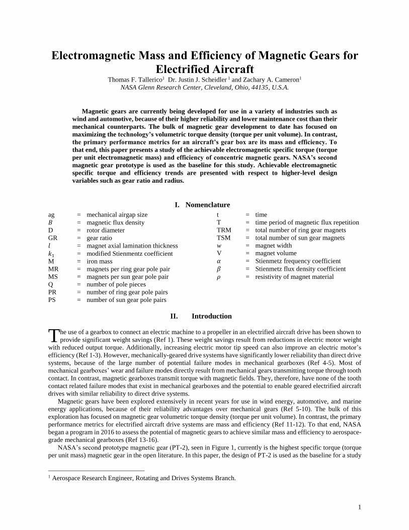
NASA’s second prototype magnetic gear (PT-2), seen in Figure 1, currently is the highest specific torque (torque
per unit mass) magnetic gear in the open literature. In this paper, the design of PT-2 is used as the baseline for a study
1 Aerospace Research Engineer, Rotating and Drives Systems Branch.
T
2
of concentric magnetic gear’s achievable specific torque (torque per unit mass) and efficiency. Electromagnetic
specific torque and efficiency trends for concentric magnetic gears are presented with respect to higher-level magnetic
gear design variables such as gear ratio and radius. Work by Texas A&M University (Ref 17-19) represent the only
known similar studies of concentric magnetic gears’ potential specific torque and efficiency. Their studies, however,
did not explore gears designed with Halbach arrays, which have been shown to improve magnetic gear specific torque
(Ref 20). Their studies also assumed a minimum modulator radial thicknesses two times larger than what was achieved
in NASA’s second prototype. As discussed in References 13-16, Modulator radial thickness is one of the main drivers
of a magnetic gear’s specific torque. Additionally, their study was conducted for grade N42 neodymium magnets,
most likely to limit cost. Higher grade neodymium magnets are more practical for aerospace applications because cost
is less of a factor. Grade N52 neodymium is considered in this study, because it was the magnet grade used in PT-2.
Figure 1 NASA's second prototype magnetic gear (PT-2)
In Section III of this paper, a brief description of concentric magnetic gears is provided. Section IV explains the
methodology used in the specific torque and efficiency studies presented in this paper. Sections V-IX discuss magnetic
gear efficiency and specific torque with respect to magnets per ring gear pole pair (MR), magnets per sun gear pole
pair (MS), number of sun gear pole pairs (PS), gear ratio, and radius. Section X provides a discussion of the trends
between concentric magnetic gear mass and efficiency.
III. Concentric Magnetic Gears
The concept of the concentric magnetic gear (CMG) was first proposed in 2004 (Ref 21). A concentric magnetic gear
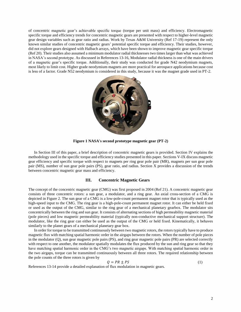
consists of three concentric rotors: a sun gear, a modulator, and a ring gear. An axial cross-section of a CMG is
depicted in Figure 2. The sun gear of a CMG is a low-pole-count permanent magnet rotor that is typically used as the
high-speed input to the CMG. The ring gear is a high-pole-count permanent magnet rotor. It can either be held fixed
or used as the output of the CMG, similar to the ring gear of a mechanical planetary gearbox. The modulator sits
concentrically between the ring and sun gear. It consists of alternating sections of high permeability magnetic material
(pole pieces) and low magnetic permeability material (typically non-conductive mechanical support structure). The
modulator, like the ring gear can either be used as the output of the CMG or held fixed. Kinematically, it behaves
similarly to the planet gears of a mechanical planetary gear box.
In order for torque to be transmitted continuously between two magnetic rotors, the rotors typically have to produce
magnetic flux with matching spatial harmonic order in the airgaps between the rotors. When the number of pole pieces
in the modulator (Q), sun gear magnetic pole pairs (PS), and ring gear magnetic pole pairs (PR) are selected correctly
with respect to one another, the modulator spatially modulates the flux produced by the sun and ring gear so that they
have matching spatial harmonic order in the CMG’s two magnetic airgaps. With matching spatial harmonic order in
the two airgaps, torque can be transmitted continuously between all three rotors. The required relationship between
the pole counts of the three rotors is given by
𝑄 = 𝑃𝑅 ± 𝑃𝑆 (1)
References 13-14 provide a detailed explanation of flux modulation in magnetic gears.
3
Figure 2 Cross-sectional geometry of a simple concentric magnetic gear
In this paper, the number of pole pieces is assumed to be equal to the number of ring gear pole pairs plus the number
of sun gear pole pairs. The ring gear is assumed to be fixed and the modulator is used as the output of the CMG. In
this configuration, the gear ratio is given by
𝐺𝑅 =𝑄
𝑃𝑆=
𝑃𝑅
𝑃𝑆+ 1 (2)
IV. Study Methodology
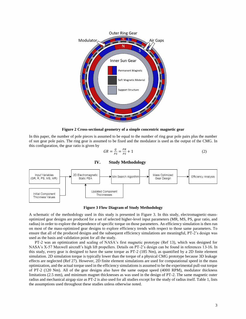
Figure 3 Flow Diagram of Study Methodology
A schematic of the methodology used in this study is presented in Figure 3. In this study, electromagnetic-mass-
optimized gear designs are produced for a set of selected higher-level input parameters (MR, MS, PS, gear ratio, and
radius) in order to explore the dependence of specific torque on those parameters. An efficiency simulation is then run
on most of the mass-optimized gear designs to explore efficiency trends with respect to those same parameters. To
ensure that all of the produced designs and the subsequent efficiency simulations are meaningful, PT-2’s design was
used as the basis and validation point for all the study.
PT-2 was an optimization and scaling of NASA’s first magnetic prototype (Ref 13), which was designed for
NASA’s X-57 Maxwell aircraft’s high lift propellers. Details on PT-2’s design can be found in references 13-16. In
this study, every gear is designed to have the same torque as PT-2 (185 Nm), as quantified by a 2D finite element
simulation. 2D simulation torque is typically lower than the torque of a physical CMG prototype because 3D leakage
effects are neglected (Ref 27). However, 2D finite element simulations are used for computational speed in the mass
optimization, and the actual torque used in the efficiency simulations is assumed to be the experimental pull-out torque
of PT-2 (120 Nm). All of the gear designs also have the same output speed (4000 RPM), modulator thickness
limitations (2.5 mm), and minimum magnet thicknesses as was used in the design of PT-2. The same magnetic outer
radius and mechanical airgap size as PT-2 is also used for all studies except for the study of radius itself. Table 1, lists
the assumptions used throughout these studies unless otherwise noted.
4
Table 1 Design parameters held constant throughout the study and their assumed values unless otherwise
noted.
Parameter Metric English
Outer Diameter 140 mm 5.51 in
2D Output Torque 185 Nm 1637 in lbf
3D Output Torque 120 Nm 1062 in lbf
Output Speed 4000 RPM
Mechanical Airgap Thickness 1 mm 0.0394 in
Min Sun Magnet Thickness 5 mm 0.197 in
Min Pole Piece Thickness 2.5 mm 0.0984 in
Min Ring Magnet Thickness 3 mm 0.118 in
Thickness of Walls Between Magnets 0.5 mm 0.0197 in
Inner Pole Piece Span Angle (rad) 1.2*π/PR
Mid Pole Piece Span Angle (rad) 1.2*π/PR
Outer Pole Piece Span Angle (rad) .6*π/PR
Magnetic Material Neodymium N52
Electrical Steel Fe49Co49V2
Density of Magnets 7500 kg/m^3 0.271 lb/in^3
Density of Pole Pieces 8000 kg/m^3 0.289 ln/in^3
Allowable Stress in Carbon Fiber 600 MPa 87 ksi
A. Specific Torque Optimized Gear Design Methodology
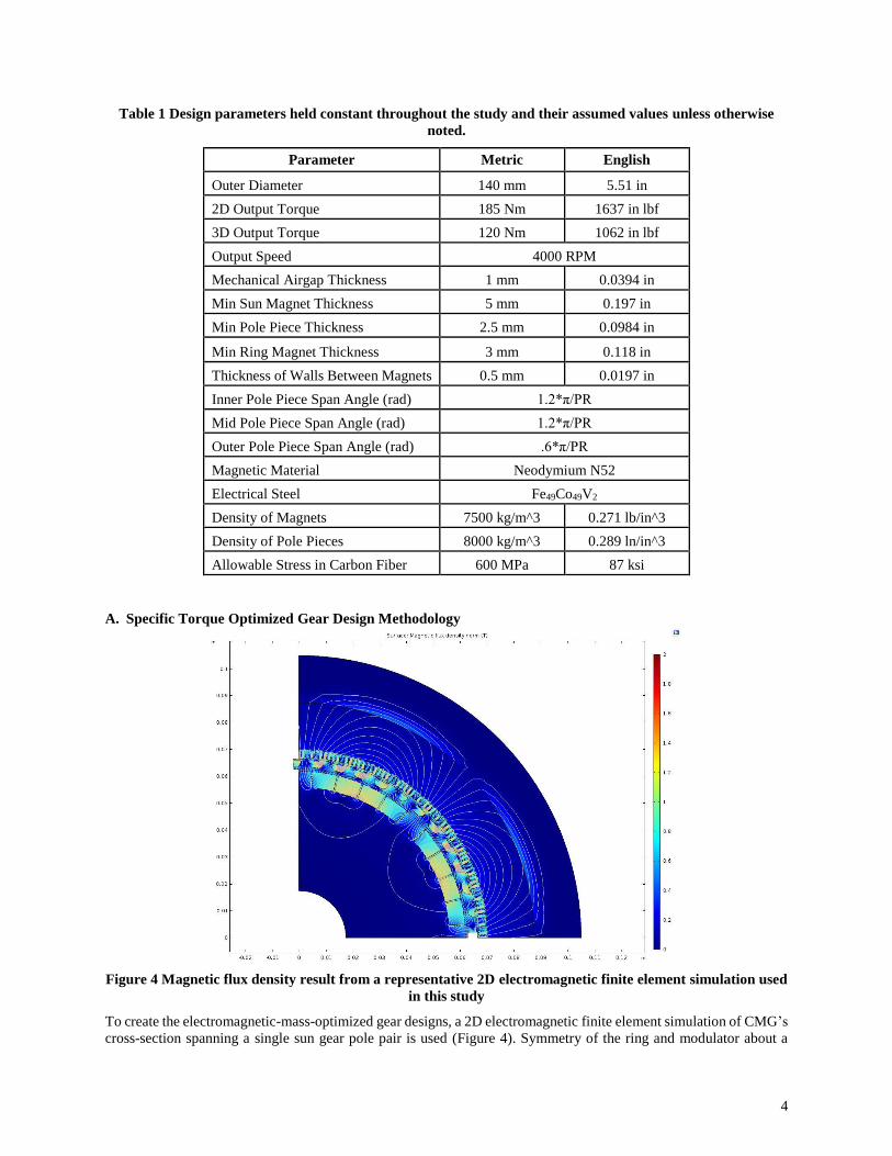
Figure 4 Magnetic flux density result from a representative 2D electromagnetic finite element simulation used
in this study
To create the electromagnetic-mass-optimized gear designs, a 2D electromagnetic finite element simulation of CMG’s
cross-section spanning a single sun gear pole pair is used (Figure 4). Symmetry of the ring and modulator about a
5
single sun gear pole pair is enabled through the use of integer gear ratios. This symmetry was inforced for
computational efficiency. In actual CMG prototypes, integer gear ratios should be avoided because the symmetry they
create leads to a large amount of cogging torque and torque ripple (Ref 22-23). A minimum search algorithm is used
to optimize the sun gear magnet, pole piece, and ring gear magnet thicknesses to maximize specific torque. Definitions
of these thicknesses are shown in Figure 5.
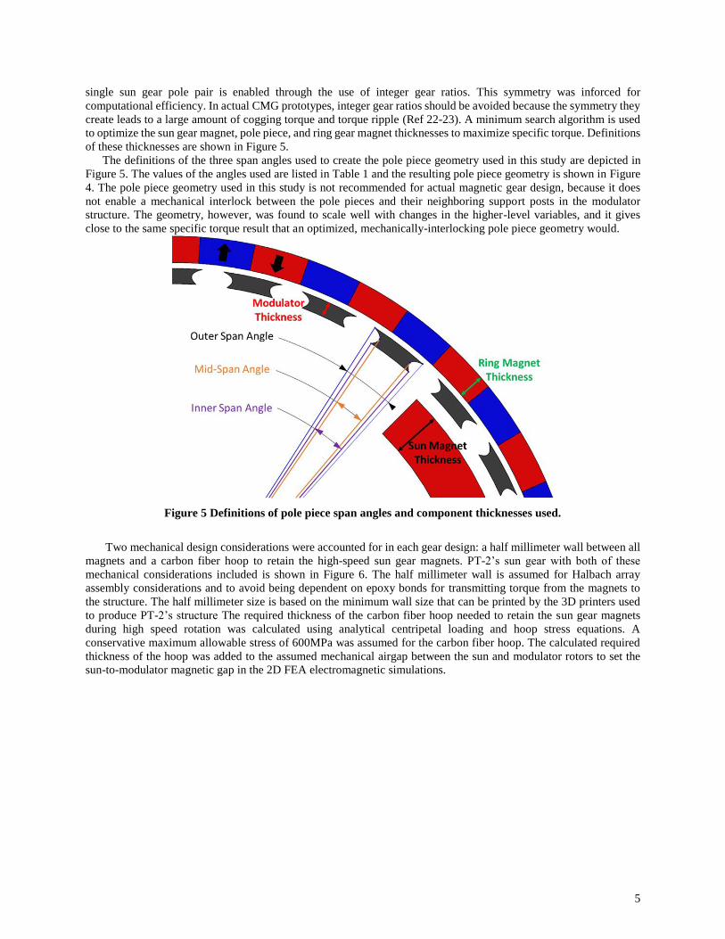
The definitions of the three span angles used to create the pole piece geometry used in this study are depicted in
Figure 5. The values of the angles used are listed in Table 1 and the resulting pole piece geometry is shown in Figure
4. The pole piece geometry used in this study is not recommended for actual magnetic gear design, because it does
not enable a mechanical interlock between the pole pieces and their neighboring support posts in the modulator
structure. The geometry, however, was found to scale well with changes in the higher-level variables, and it gives
close to the same specific torque result that an optimized, mechanically-interlocking pole piece geometry would.
Figure 5 Definitions of pole piece span angles and component thicknesses used.
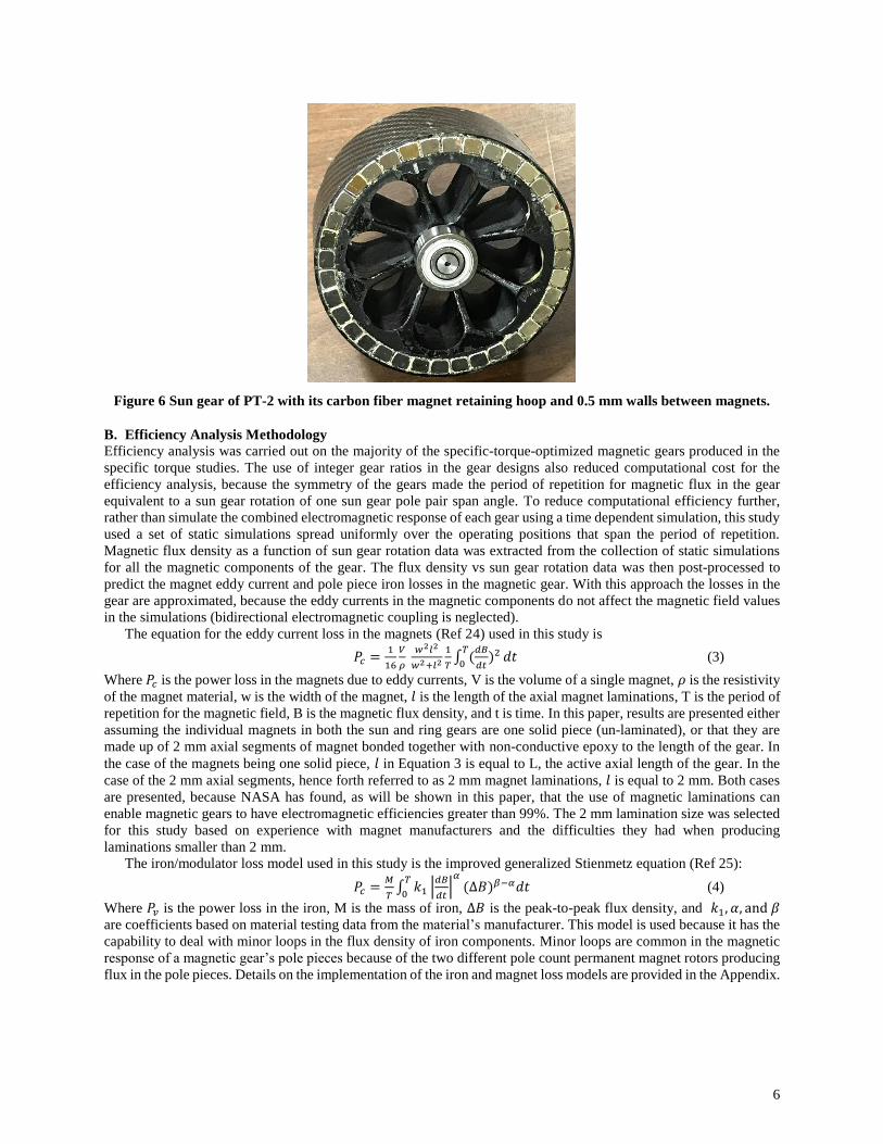
Two mechanical design considerations were accounted for in each gear design: a half millimeter wall between all
magnets and a carbon fiber hoop to retain the high-speed sun gear magnets. PT-2’s sun gear with both of these
mechanical considerations included is shown in Figure 6. The half millimeter wall is assumed for Halbach array
assembly considerations and to avoid being dependent on epoxy bonds for transmitting torque from the magnets to
the structure. The half millimeter size is based on the minimum wall size that can be printed by the 3D printers used
to produce PT-2’s structure The required thickness of the carbon fiber hoop needed to retain the sun gear magnets
during high speed rotation was calculated using analytical centripetal loading and hoop stress equations. A
conservative maximum allowable stress of 600MPa was assumed for the carbon fiber hoop. The calculated required
thickness of the hoop was added to the assumed mechanical airgap between the sun and modulator rotors to set the
sun-to-modulator magnetic gap in the 2D FEA electromagnetic simulations.
6
Figure 6 Sun gear of PT-2 with its carbon fiber magnet retaining hoop and 0.5 mm walls between magnets.
B. Efficiency Analysis Methodology
Efficiency analysis was carried out on the majority of the specific-torque-optimized magnetic gears produced in the
specific torque studies. The use of integer gear ratios in the gear designs also reduced computational cost for the
efficiency analysis, because the symmetry of the gears made the period of repetition for magnetic flux in the gear
equivalent to a sun gear rotation of one sun gear pole pair span angle. To reduce computational efficiency further,
rather than simulate the combined electromagnetic response of each gear using a time dependent simulation, this study
used a set of static simulations spread uniformly over the operating positions that span the period of repetition.
Magnetic flux density as a function of sun gear rotation data was extracted from the collection of static simulations
for all the magnetic components of the gear. The flux density vs sun gear rotation data was then post-processed to
predict the magnet eddy current and pole piece iron losses in the magnetic gear. With this approach the losses in the
gear are approximated, because the eddy currents in the magnetic components do not affect the magnetic field values
in the simulations (bidirectional electromagnetic coupling is neglected).
The equation for the eddy current loss in the magnets (Ref 24) used in this study is
𝑃𝑐 =1
16
𝑉
𝜌
𝑤2𝑙2
𝑤2+𝑙2
1
𝑇∫ (
𝑑𝐵
𝑑𝑡)2𝑇
0𝑑𝑡 (3)
Where 𝑃𝑐 is the power loss in the magnets due to eddy currents, V is the volume of a single magnet, 𝜌 is the resistivity
of the magnet material, w is the width of the magnet, 𝑙 is the length of the axial magnet laminations, T is the period of
repetition for the magnetic field, B is the magnetic flux density, and t is time. In this paper, results are presented either
assuming the individual magnets in both the sun and ring gears are one solid piece (un-laminated), or that they are
made up of 2 mm axial segments of magnet bonded together with non-conductive epoxy to the length of the gear. In
the case of the magnets being one solid piece, 𝑙 in Equation 3 is equal to L, the active axial length of the gear. In the
case of the 2 mm axial segments, hence forth referred to as 2 mm magnet laminations, 𝑙 is equal to 2 mm. Both cases
are presented, because NASA has found, as will be shown in this paper, that the use of magnetic laminations can
enable magnetic gears to have electromagnetic efficiencies greater than 99%. The 2 mm lamination size was selected
for this study based on experience with magnet manufacturers and the difficulties they had when producing
laminations smaller than 2 mm.
The iron/modulator loss model used in this study is the improved generalized Stienmetz equation (Ref 25):
𝑃𝑐 =𝑀
𝑇∫ 𝑘1 |
𝑑𝐵
𝑑𝑡|
𝛼
(∆𝐵)𝛽−𝛼𝑑𝑡𝑇
0 (4)
Where 𝑃𝑣 is the power loss in the iron, M is the mass of iron, ∆𝐵 is the peak-to-peak flux density, and 𝑘1, 𝛼, and 𝛽
are coefficients based on material testing data from the material’s manufacturer. This model is used because it has the
capability to deal with minor loops in the flux density of iron components. Minor loops are common in the magnetic
response of a magnetic gear’s pole pieces because of the two different pole count permanent magnet rotors producing
flux in the pole pieces. Details on the implementation of the iron and magnet loss models are provided in the Appendix.
7
V. Effect of Magnets per Ring Gear Pole Pair (MR)
MR and MS are included in this study to show separately the effects of total ring magnet count (TRM) and total sun
magnet count (TSM) on magnetic gear specific torque and efficiency independent of sun and ring gear pole count
changes. For the study of MR an outer radius of 7 cm and a gear ratio of 4 was used similar to PT-2. MS was set to
10. Parametric sweeps of PS and MR were performed and mass optimized gear designs were produced for each
combination. Table 2 lists the higher-level variable values used in this study.
Table 2 Higher-level variable values for MR study
MR Study Parameters
Radius 7 cm
Gear Ratio 4
Sun Gear Pole Pairs (PS) 4, 6, 8, 10, 12
Magnets per Sun Gear Pole Pair (MS) 10
Magnets per Ring Gear Pole Pair (MR) 4, 6, 8, 10
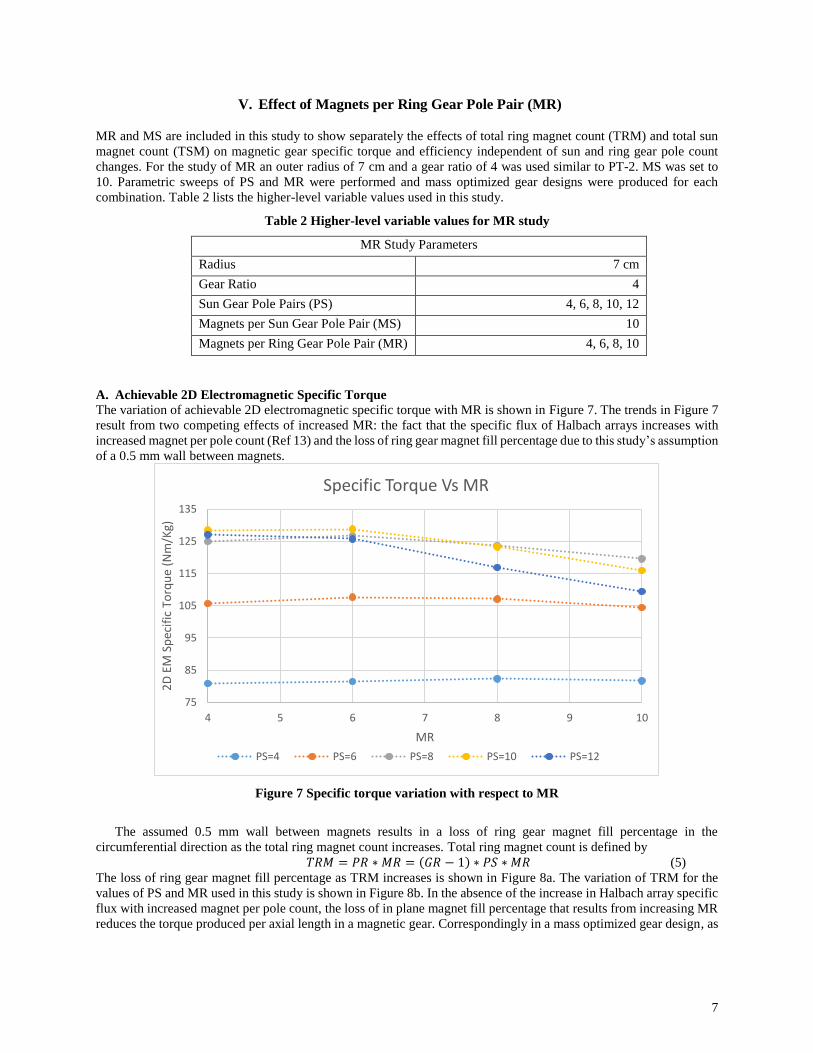
A. Achievable 2D Electromagnetic Specific Torque
The variation of achievable 2D electromagnetic specific torque with MR is shown in Figure 7. The trends in Figure 7
result from two competing effects of increased MR: the fact that the specific flux of Halbach arrays increases with
increased magnet per pole count (Ref 13) and the loss of ring gear magnet fill percentage due to this study’s assumption
of a 0.5 mm wall between magnets.
Figure 7 Specific torque variation with respect to MR
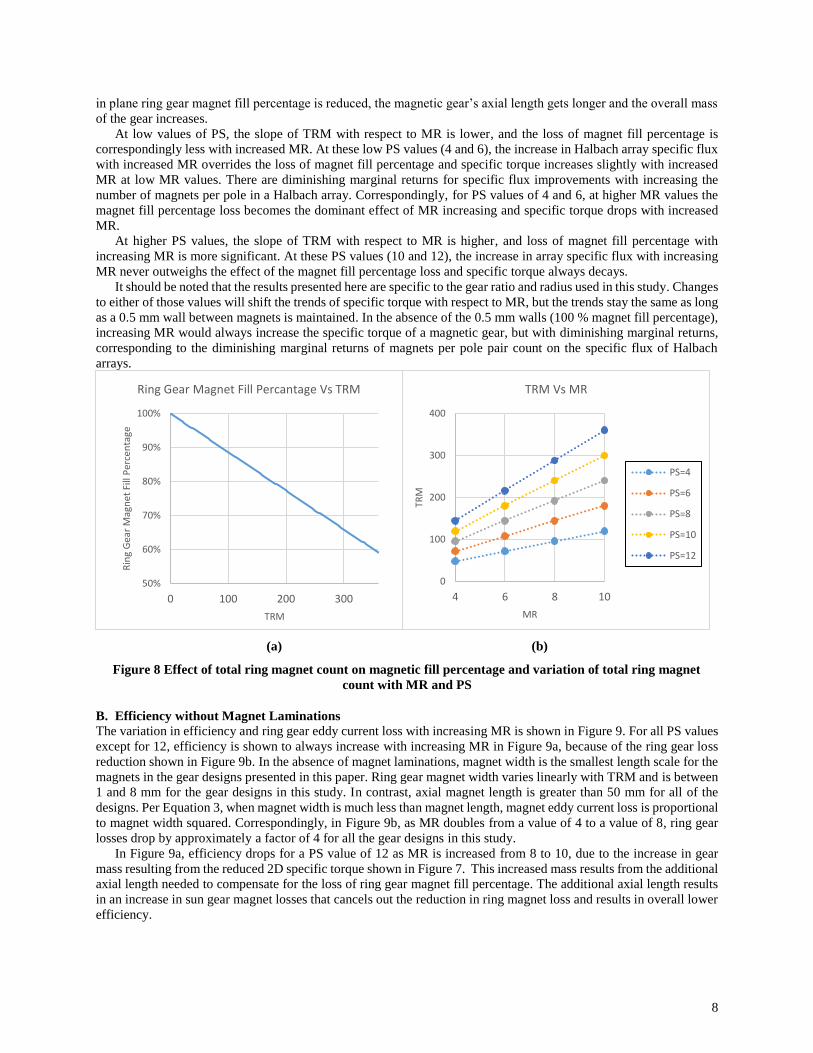
The assumed 0.5 mm wall between magnets results in a loss of ring gear magnet fill percentage in the
circumferential direction as the total ring magnet count increases. Total ring magnet count is defined by
𝑇𝑅𝑀 = 𝑃𝑅 ∗ 𝑀𝑅 = (𝐺𝑅 − 1) ∗ 𝑃𝑆 ∗ 𝑀𝑅 (5)
The loss of ring gear magnet fill percentage as TRM increases is shown in Figure 8a. The variation of TRM for the
values of PS and MR used in this study is shown in Figure 8b. In the absence of the increase in Halbach array specific
flux with increased magnet per pole count, the loss of in plane magnet fill percentage that results from increasing MR
reduces the torque produced per axial length in a magnetic gear. Correspondingly in a mass optimized gear design, as
75
85
95
105
115
125
135
4 5 6 7 8 9 10
2D
EM
Sp
ecif
ic T
orq
ue
(Nm
/Kg)
MR
Specific Torque Vs MR
PS=4 PS=6 PS=8 PS=10 PS=12
8
in plane ring gear magnet fill percentage is reduced, the magnetic gear’s axial length gets longer and the overall mass
of the gear increases.
At low values of PS, the slope of TRM with respect to MR is lower, and the loss of magnet fill percentage is
correspondingly less with increased MR. At these low PS values (4 and 6), the increase in Halbach array specific flux
with increased MR overrides the loss of magnet fill percentage and specific torque increases slightly with increased
MR at low MR values. There are diminishing marginal returns for specific flux improvements with increasing the
number of magnets per pole in a Halbach array. Correspondingly, for PS values of 4 and 6, at higher MR values the
magnet fill percentage loss becomes the dominant effect of MR increasing and specific torque drops with increased
MR.
At higher PS values, the slope of TRM with respect to MR is higher, and loss of magnet fill percentage with
increasing MR is more significant. At these PS values (10 and 12), the increase in array specific flux with increasing
MR never outweighs the effect of the magnet fill percentage loss and specific torque always decays.
It should be noted that the results presented here are specific to the gear ratio and radius used in this study. Changes
to either of those values will shift the trends of specific torque with respect to MR, but the trends stay the same as long
as a 0.5 mm wall between magnets is maintained. In the absence of the 0.5 mm walls (100 % magnet fill percentage),
increasing MR would always increase the specific torque of a magnetic gear, but with diminishing marginal returns,
corresponding to the diminishing marginal returns of magnets per pole pair count on the specific flux of Halbach
arrays.
(a) (b)
Figure 8 Effect of total ring magnet count on magnetic fill percentage and variation of total ring magnet
count with MR and PS
B. Efficiency without Magnet Laminations
The variation in efficiency and ring gear eddy current loss with increasing MR is shown in Figure 9. For all PS values
except for 12, efficiency is shown to always increase with increasing MR in Figure 9a, because of the ring gear loss
reduction shown in Figure 9b. In the absence of magnet laminations, magnet width is the smallest length scale for the
magnets in the gear designs presented in this paper. Ring gear magnet width varies linearly with TRM and is between
1 and 8 mm for the gear designs in this study. In contrast, axial magnet length is greater than 50 mm for all of the
designs. Per Equation 3, when magnet width is much less than magnet length, magnet eddy current loss is proportional
to magnet width squared. Correspondingly, in Figure 9b, as MR doubles from a value of 4 to a value of 8, ring gear
losses drop by approximately a factor of 4 for all the gear designs in this study.
In Figure 9a, efficiency drops for a PS value of 12 as MR is increased from 8 to 10, due to the increase in gear
mass resulting from the reduced 2D specific torque shown in Figure 7. This increased mass results from the additional
axial length needed to compensate for the loss of ring gear magnet fill percentage. The additional axial length results
in an increase in sun gear magnet losses that cancels out the reduction in ring magnet loss and results in overall lower
efficiency.
50%
60%
70%
80%
90%
100%
0 100 200 300
Rin
g G
ear
Mag
net
Fill
Per
cen
tage
TRM
Ring Gear Magnet Fill Percantage Vs TRM
0
100
200
300
400
4 6 8 10
TRM
MR
TRM Vs MR
PS=4
PS=6
PS=8
PS=10
PS=12
9
(a) (b)
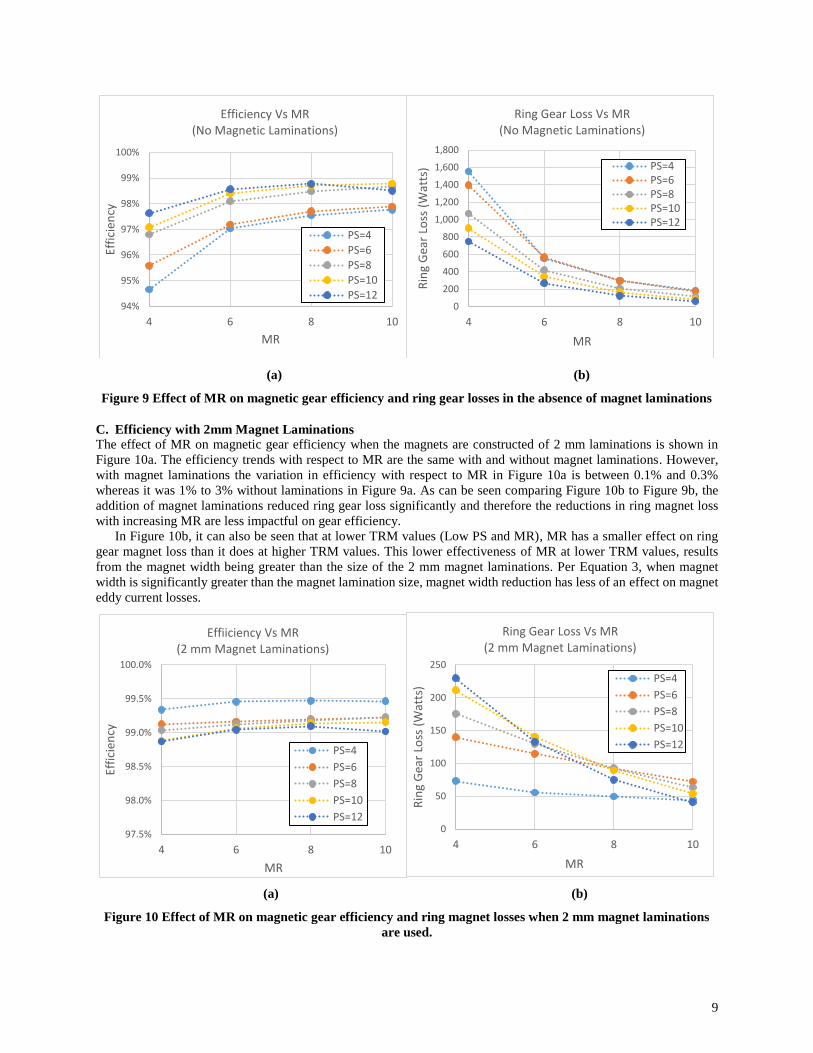
Figure 9 Effect of MR on magnetic gear efficiency and ring gear losses in the absence of magnet laminations
C. Efficiency with 2mm Magnet Laminations
The effect of MR on magnetic gear efficiency when the magnets are constructed of 2 mm laminations is shown in
Figure 10a. The efficiency trends with respect to MR are the same with and without magnet laminations. However,
with magnet laminations the variation in efficiency with respect to MR in Figure 10a is between 0.1% and 0.3%
whereas it was 1% to 3% without laminations in Figure 9a. As can be seen comparing Figure 10b to Figure 9b, the
addition of magnet laminations reduced ring gear loss significantly and therefore the reductions in ring magnet loss
with increasing MR are less impactful on gear efficiency.
In Figure 10b, it can also be seen that at lower TRM values (Low PS and MR), MR has a smaller effect on ring
gear magnet loss than it does at higher TRM values. This lower effectiveness of MR at lower TRM values, results
from the magnet width being greater than the size of the 2 mm magnet laminations. Per Equation 3, when magnet
width is significantly greater than the magnet lamination size, magnet width reduction has less of an effect on magnet
eddy current losses.
(a) (b)
Figure 10 Effect of MR on magnetic gear efficiency and ring magnet losses when 2 mm magnet laminations
are used.
94%
95%
96%
97%
98%
99%
100%
4 6 8 10
Effi
cien
cy
MR
Efficiency Vs MR (No Magnetic Laminations)
PS=4
PS=6
PS=8PS=10
PS=120
200
400
600
800
1,000
1,200
1,400
1,600
1,800
4 6 8 10
Rin
g G
ear
Loss
(W
atts
)
MR
Ring Gear Loss Vs MR (No Magnetic Laminations)
PS=4PS=6PS=8PS=10PS=12
97.5%
98.0%
98.5%
99.0%
99.5%
100.0%
4 6 8 10
Effi
cien
cy
MR
Effiiciency Vs MR(2 mm Magnet Laminations)
PS=4
PS=6
PS=8
PS=10
PS=120
50
100
150
200
250
4 6 8 10
Rin
g G
ear
Loss
(W
atts
)
MR
Ring Gear Loss Vs MR (2 mm Magnet Laminations)
PS=4
PS=6
PS=8
PS=10
PS=12
10
Overall, comparing Figure 10a to Figure 9a, the addition of magnet laminations enabled most the gear designs to
achieve greater than 99% electromagnetic efficiency. This result is one of the key findings of NASA’s magnetic
gearing program as these efficiency values are comparable to the efficiencies typically achieved by aerospace grade
mechanical gearboxes.
VI. Effect of Magnets per Sun Gear Pole Pair (MS)
For the study of MS, similar to MR a radius of 7 cm and a gear ratio of 4 was assumed. MR was held fixed at 6.
Parametric sweeps of PS and MS were performed. Table 3 lists the values of the higher-level variables used in the MS
study.
Table 3 Higher-level variable values used in MS study
MS Study Parameters
Radius 7 cm
Gear Ratio 4
Sun Gear Pole Pairs (PS) 4, 6, 8, 10, 12
Magnets per Sun Gear Pole Pair (MS) 4, 6, 8, 10, 12
Magnets per Ring Gear Pole Pair (MR) 6
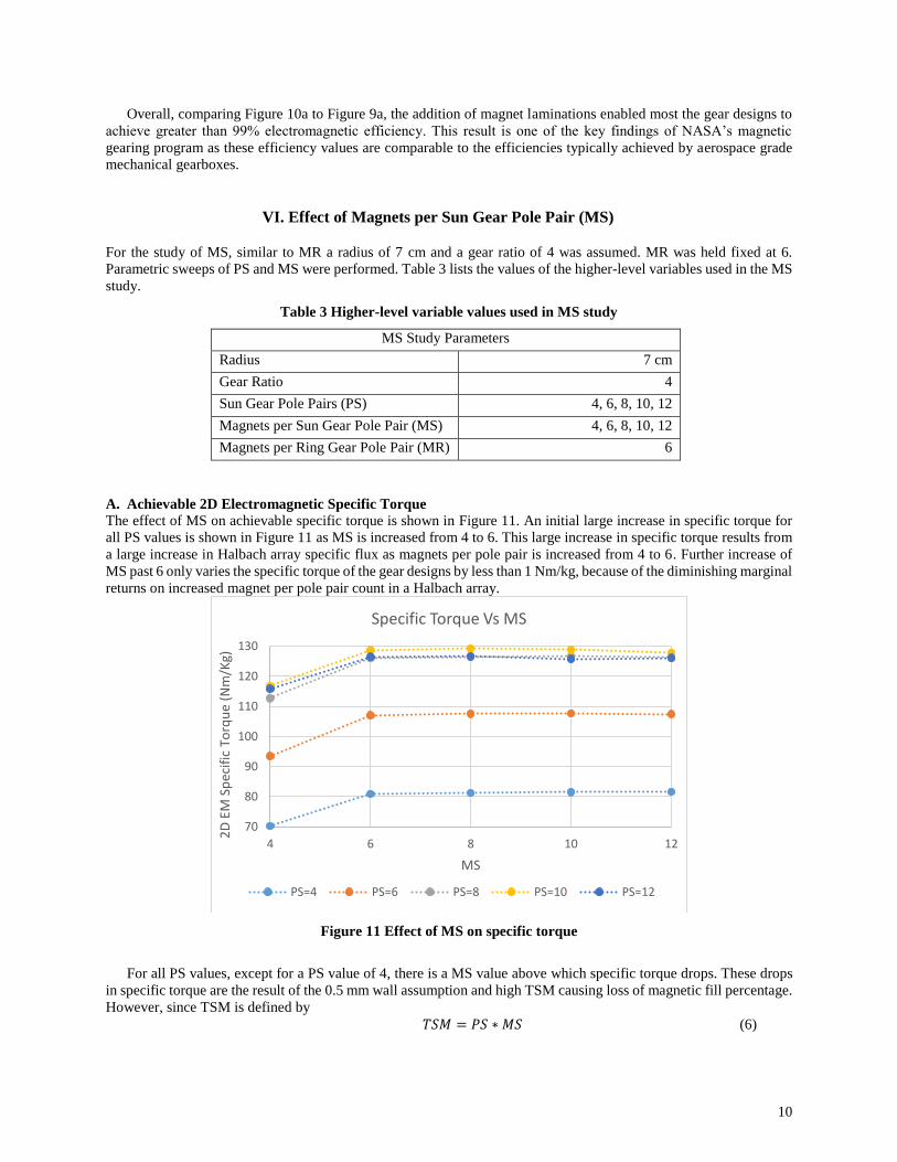
A. Achievable 2D Electromagnetic Specific Torque
The effect of MS on achievable specific torque is shown in Figure 11. An initial large increase in specific torque for
all PS values is shown in Figure 11 as MS is increased from 4 to 6. This large increase in specific torque results from
a large increase in Halbach array specific flux as magnets per pole pair is increased from 4 to 6. Further increase of
MS past 6 only varies the specific torque of the gear designs by less than 1 Nm/kg, because of the diminishing marginal
returns on increased magnet per pole pair count in a Halbach array.
Figure 11 Effect of MS on specific torque
For all PS values, except for a PS value of 4, there is a MS value above which specific torque drops. These drops
in specific torque are the result of the 0.5 mm wall assumption and high TSM causing loss of magnetic fill percentage.
However, since TSM is defined by
𝑇𝑆𝑀 = 𝑃𝑆 ∗ 𝑀𝑆 (6)
70
80
90
100
110
120
130
4 6 8 10 12
2D
EM
Sp
ecif
ic T
orq
ue
(Nm
/Kg)
MS
Specific Torque Vs MS
PS=4 PS=6 PS=8 PS=10 PS=12

11
the increase in TSM with increased MS is three times less steep than the increase of TRM with MR for the gear ratio
assumed in this study. Magnet fill percentage is therefore lost more gradually as MS increases. As a result, no
significant loss of specific torque is shown in Figure 11, even at the highest MS and PS values used in this study.
B. Efficiency without Magnet Laminations
The effects of MS on magnetic gear efficiency and sun gear magnet loss in the absence of magnet laminations are
shown in Figure 12. Similar to ring gear magnet losses, in the absence of magnet laminations, sun gear magnet losses
decrease with approximately the square of sun magnet width which decreases linearly with increased MS.
Correspondingly, efficiency increases as MS is increased for all of the gear designs.
(a) (b)
Figure 12 Effect of MS on magnetic gear efficiency and sun gear losses
Comparing ring gear magnet losses in Figure 9b to sun gear magnet losses in Figure 12b, sun gear magnet losses
are shown to be significantly higher. Sun gear magnet losses are higher in these studies for three reasons: TSM is
significantly lower than TRM for the parameter values used in this study and correspondingly sun magnet width is
much larger than ring magnet width; the sun magnets in all of the designs are approximately two times thicker than
the ring gear magnets and therefore have approximately double the volume; and the frequency of the ring gear pole
passage on the sun gear at a gear ratio of four is three times the frequency of sun gear pole passage on the ring gear.
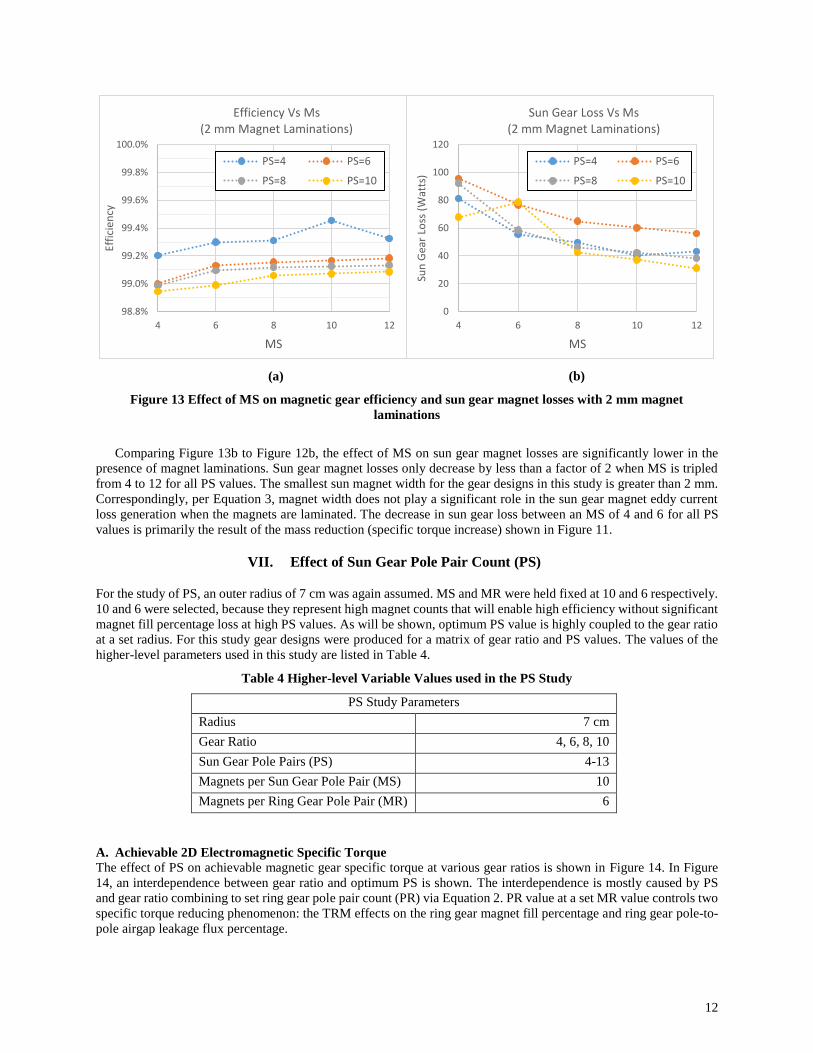
C. Efficiency with 2mm Magnet Laminations
The effect of MS on magnetic gear efficiency and sun gear magnet losses with 2 mm magnet laminations is shown in
Figure 13. Similar to the variation of efficiency with MR when 2 mm magnetic laminations are used, the variation in
efficiency with MS when the magnets are laminated is very small (<0.2 %).
80%
84%
88%
92%
96%
100%
4 6 8 10 12
Effi
cien
cy
MS
Efficiency Vs Ms(No Magnet Laminations)
PS=4
PS=6
PS=8
PS=10
0
1000
2000
3000
4000
5000
6000
7000
8000
4 6 8 10 12
Sun
Gea
r Lo
ss (
Wat
ts)
MS
Sun Gear Loss Vs Ms(No Magnet Laminations)
PS=4
PS=6
PS=8
PS=10
12
(a) (b)
Figure 13 Effect of MS on magnetic gear efficiency and sun gear magnet losses with 2 mm magnet
laminations
Comparing Figure 13b to Figure 12b, the effect of MS on sun gear magnet losses are significantly lower in the
presence of magnet laminations. Sun gear magnet losses only decrease by less than a factor of 2 when MS is tripled
from 4 to 12 for all PS values. The smallest sun magnet width for the gear designs in this study is greater than 2 mm.
Correspondingly, per Equation 3, magnet width does not play a significant role in the sun gear magnet eddy current
loss generation when the magnets are laminated. The decrease in sun gear loss between an MS of 4 and 6 for all PS
values is primarily the result of the mass reduction (specific torque increase) shown in Figure 11.
VII. Effect of Sun Gear Pole Pair Count (PS)
For the study of PS, an outer radius of 7 cm was again assumed. MS and MR were held fixed at 10 and 6 respectively.
10 and 6 were selected, because they represent high magnet counts that will enable high efficiency without significant
magnet fill percentage loss at high PS values. As will be shown, optimum PS value is highly coupled to the gear ratio
at a set radius. For this study gear designs were produced for a matrix of gear ratio and PS values. The values of the
higher-level parameters used in this study are listed in Table 4.
Table 4 Higher-level Variable Values used in the PS Study
PS Study Parameters
Radius 7 cm
Gear Ratio 4, 6, 8, 10
Sun Gear Pole Pairs (PS) 4-13
Magnets per Sun Gear Pole Pair (MS) 10
Magnets per Ring Gear Pole Pair (MR) 6
A. Achievable 2D Electromagnetic Specific Torque
The effect of PS on achievable magnetic gear specific torque at various gear ratios is shown in Figure 14. In Figure
14, an interdependence between gear ratio and optimum PS is shown. The interdependence is mostly caused by PS
and gear ratio combining to set ring gear pole pair count (PR) via Equation 2. PR value at a set MR value controls two
specific torque reducing phenomenon: the TRM effects on the ring gear magnet fill percentage and ring gear pole-to-
pole airgap leakage flux percentage.
98.8%
99.0%
99.2%
99.4%
99.6%
99.8%
100.0%
4 6 8 10 12
Effi
cien
cy
MS
Efficiency Vs Ms(2 mm Magnet Laminations)
PS=4 PS=6
PS=8 PS=10
0
20
40
60
80
100
120
4 6 8 10 12
Sun
Gea
r Lo
ss (
Wat
ts)
MS
Sun Gear Loss Vs Ms(2 mm Magnet Laminations)
PS=4 PS=6
PS=8 PS=10

13
Ring gear pole-to-pole airgap flux leakage is flux that links between two poles on the ring gear through the airgap
rather than crossing the airgap into the modulator. This flux that leaks pole-to-pole on the ring gear does not couple
with the sun gear flux and therefore does not produce torque. The percent of the ring gear’s flux that leaks pole-to-
pole is determined by the relative reluctance of the coupling and leakage flux paths. The reluctance of the coupling
path is largely set by the thickness of the CMG’s airgaps. The reluctance of the pole-to-pole leakage path is mostly
driven by the circumferential distance between poles on the ring gear. The relative ratio of the airgap thickness to the
ring gear pole-to-pole distance therefore governs what percent of the ring gear’s flux leaks pole-to-pole. At a set radius
pole-to-pole distance decreases linearly with increasing PR. Correspondingly ring gear pole-to-pole leakage
percentage increases.
By the nature of Equation 2, PR is significantly larger than PS and the ring gear’s pole-to-pole distance is shorter
than that of the sun gear. As a result, a higher percentage of the ring gear flux leaks pole-to-pole than sun gear flux.
Correspondingly, additional magnet material is more effective at producing torque on the sun gear than it would be
on the ring gear, because a higher percentage of the added material’s flux will be in the coupling path. As a result, the
ring gear magnets are typically radially thinner than the sun gear magnets in a mass or volume optimized CMG design.
In the absence of ring gear pole-to-pole leakage and magnet fill percentage effects, specific torque would always
increase with increased PS. Increasing PS reduces pole-to-pole distance on the gears’ Halbach arrays. Reduced pole-
to-pole distance improves array specific flux (Ref 13) and reduces the optimal modulator thickness. Optimal modulator
thickness reduces with reduced pole-to-pole distance because the reluctance between poles is smaller and therefore
less pole piece thickness is required to significantly affect the reluctance between poles and create flux modulation.
Figure 14 Effect of PS on achievable specific torque at various gear ratios
At low PR values (low PS values and low gear ratios), ring gear pole-to-pole leakage and magnet fill percentage
effects are negligible and specific torque increases with increased PS, because the optimal modulator gets thinner and
the arrays gain specific flux. This specific torque increase can be seen in Figure 14 for a gear ratio of 4 between PS
values of 4 and 8. The specific torque increase is almost linear. At a PS value of 8 and a gear ratio of 4 in Figure 14,
the modulator reaches the 2.5 mm minimum modulator thickness limit set for this study. Beyond that point, until a PS
of 11, specific torque increase is more marginal because only the improvements to Halbach array specific flux due to
reduced pole-to-pole distance contribute to specific torque improvements.
At some point for every gear ratio in this study, increasing PS led to a drop in achievable specific torque. The PS
value at which this occurs for each gear ratio corresponds to the modulator thickness being at its minimum value and
PR being in the range of 32 to 36 pole pairs. The pole-to-pole distance on the ring gear in this PR value range is around
6 mm. This is the point where ring gear pole-to-pole flux leakage and magnet fill percentage effects become more
significant than specific flux gains for the arrays. As a result, specific torque decays with increased PS after this point.
0
20
40
60
80
100
120
140
4 6 8 10 12 14
2D
Sp
ecif
ic T
orq
ue
(Nm
/kg)
PS
Specific Torque Vs PS
GR=4 GR=6 GR=8 GR=10
14
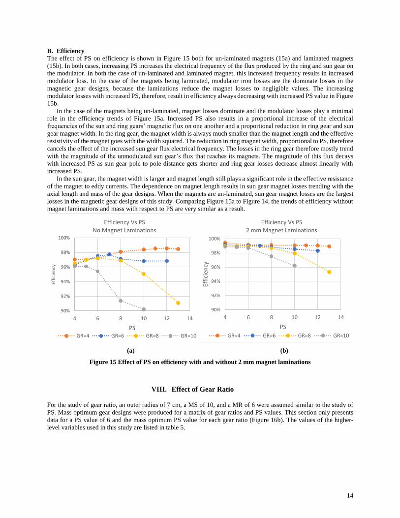
B. Efficiency
The effect of PS on efficiency is shown in Figure 15 both for un-laminated magnets (15a) and laminated magnets
(15b). In both cases, increasing PS increases the electrical frequency of the flux produced by the ring and sun gear on
the modulator. In both the case of un-laminated and laminated magnet, this increased frequency results in increased
modulator loss. In the case of the magnets being laminated, modulator iron losses are the dominate losses in the
magnetic gear designs, because the laminations reduce the magnet losses to negligible values. The increasing
modulator losses with increased PS, therefore, result in efficiency always decreasing with increased PS value in Figure
15b.
In the case of the magnets being un-laminated, magnet losses dominate and the modulator losses play a minimal
role in the efficiency trends of Figure 15a. Increased PS also results in a proportional increase of the electrical
frequencies of the sun and ring gears’ magnetic flux on one another and a proportional reduction in ring gear and sun
gear magnet width. In the ring gear, the magnet width is always much smaller than the magnet length and the effective
resistivity of the magnet goes with the width squared. The reduction in ring magnet width, proportional to PS, therefore
cancels the effect of the increased sun gear flux electrical frequency. The losses in the ring gear therefore mostly trend
with the magnitude of the unmodulated sun gear’s flux that reaches its magnets. The magnitude of this flux decays
with increased PS as sun gear pole to pole distance gets shorter and ring gear losses decrease almost linearly with
increased PS.
In the sun gear, the magnet width is larger and magnet length still plays a significant role in the effective resistance
of the magnet to eddy currents. The dependence on magnet length results in sun gear magnet losses trending with the
axial length and mass of the gear designs. When the magnets are un-laminated, sun gear magnet losses are the largest
losses in the magnetic gear designs of this study. Comparing Figure 15a to Figure 14, the trends of efficiency without
magnet laminations and mass with respect to PS are very similar as a result.
(a) (b)
Figure 15 Effect of PS on efficiency with and without 2 mm magnet laminations
VIII. Effect of Gear Ratio
For the study of gear ratio, an outer radius of 7 cm, a MS of 10, and a MR of 6 were assumed similar to the study of
PS. Mass optimum gear designs were produced for a matrix of gear ratios and PS values. This section only presents
data for a PS value of 6 and the mass optimum PS value for each gear ratio (Figure 16b). The values of the higher-
level variables used in this study are listed in table 5.
90%
92%
94%
96%
98%
100%
4 6 8 10 12 14
Effi
cien
cy
PS
Efficiency Vs PSNo Magnet Laminations
GR=4 GR=6 GR=8 GR=10
90%
92%
94%
96%
98%
100%
4 6 8 10 12 14
Effi
cien
cy
PS
Efficiency Vs PS2 mm Magnet Laminations
GR=4 GR=6 GR=8 GR=10
15
Table 5 Higher-level Variable Values used in the Gear Ratio Study
Gear Ratio Study Parameters
Radius 7 cm
Gear Ratio 4-12
Sun Gear Pole Pairs (PS) 4-13
Magnets per Sun Gear Pole Pair (MS) 10
Magnets per Ring Gear Pole Pair (MR) 6
A. Achievable 2D Electromagnetic Specific Torque
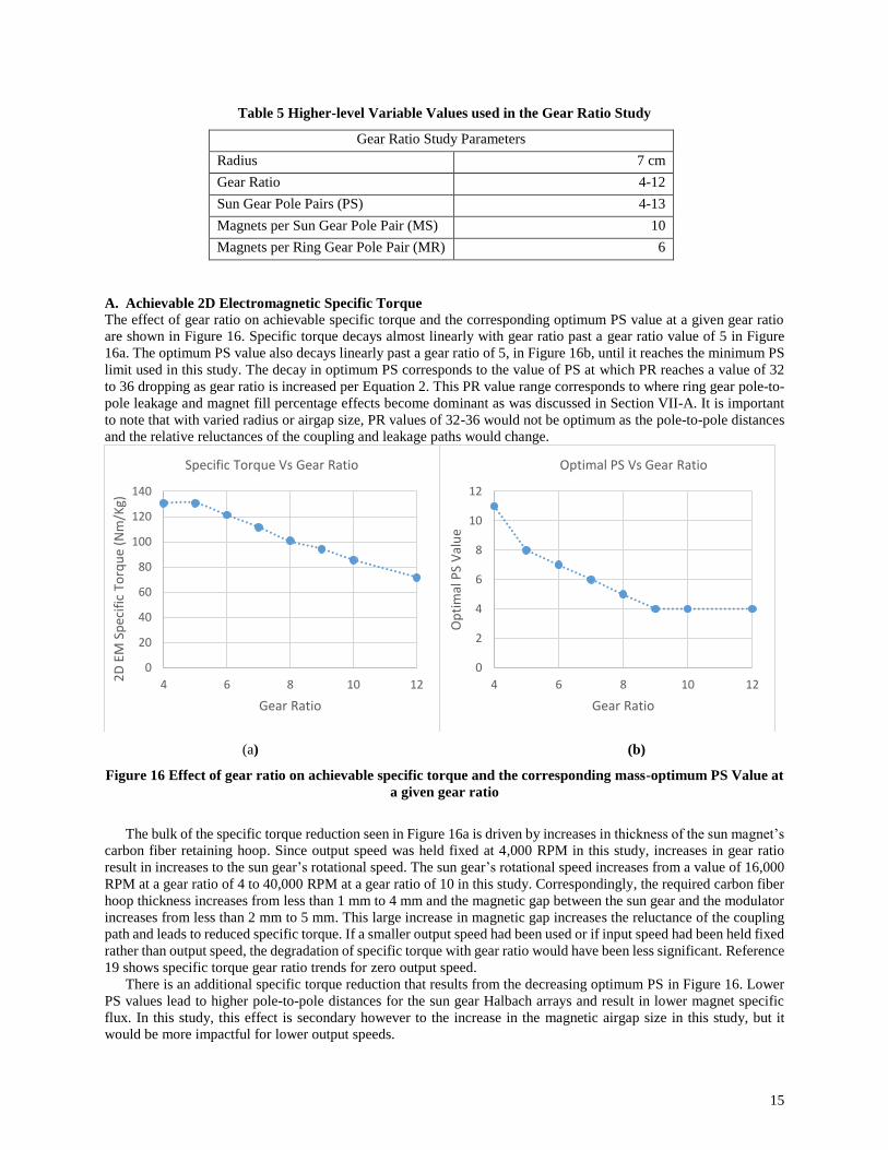
The effect of gear ratio on achievable specific torque and the corresponding optimum PS value at a given gear ratio
are shown in Figure 16. Specific torque decays almost linearly with gear ratio past a gear ratio value of 5 in Figure
16a. The optimum PS value also decays linearly past a gear ratio of 5, in Figure 16b, until it reaches the minimum PS
limit used in this study. The decay in optimum PS corresponds to the value of PS at which PR reaches a value of 32
to 36 dropping as gear ratio is increased per Equation 2. This PR value range corresponds to where ring gear pole-to-
pole leakage and magnet fill percentage effects become dominant as was discussed in Section VII-A. It is important
to note that with varied radius or airgap size, PR values of 32-36 would not be optimum as the pole-to-pole distances
and the relative reluctances of the coupling and leakage paths would change.
(a) (b)
Figure 16 Effect of gear ratio on achievable specific torque and the corresponding mass-optimum PS Value at
a given gear ratio
The bulk of the specific torque reduction seen in Figure 16a is driven by increases in thickness of the sun magnet’s
carbon fiber retaining hoop. Since output speed was held fixed at 4,000 RPM in this study, increases in gear ratio
result in increases to the sun gear’s rotational speed. The sun gear’s rotational speed increases from a value of 16,000
RPM at a gear ratio of 4 to 40,000 RPM at a gear ratio of 10 in this study. Correspondingly, the required carbon fiber
hoop thickness increases from less than 1 mm to 4 mm and the magnetic gap between the sun gear and the modulator
increases from less than 2 mm to 5 mm. This large increase in magnetic gap increases the reluctance of the coupling
path and leads to reduced specific torque. If a smaller output speed had been used or if input speed had been held fixed
rather than output speed, the degradation of specific torque with gear ratio would have been less significant. Reference
19 shows specific torque gear ratio trends for zero output speed.
There is an additional specific torque reduction that results from the decreasing optimum PS in Figure 16. Lower
PS values lead to higher pole-to-pole distances for the sun gear Halbach arrays and result in lower magnet specific
flux. In this study, this effect is secondary however to the increase in the magnetic airgap size in this study, but it
would be more impactful for lower output speeds.
0
20
40
60
80
100
120
140
4 6 8 10 12
2D
EM
Sp
ecif
ic T
orq
ue
(Nm
/Kg)
Gear Ratio
Specific Torque Vs Gear Ratio
0
2
4
6
8
10
12
4 6 8 10 12
Op
tim
al P
S V
alu
e
Gear Ratio
Optimal PS Vs Gear Ratio
16
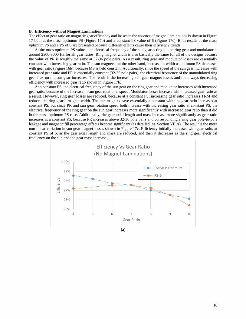
B. Efficiency without Magnet Laminations
The effect of gear ratio on magnetic gear efficiency and losses in the absence of magnet laminations is shown in Figure
17 both at the mass optimum PS (Figure 17b) and a constant PS value of 6 (Figure 17c). Both results at the mass
optimum PS and a PS of 6 are presented because different effects cause their efficiency trends.
At the mass optimum PS values, the electrical frequency of the sun gear acting on the ring gear and modulator is
around 2500-3000 Hz for all gear ratios. Ring magnet width is also basically the same for all of the designs because
the value of PR is roughly the same at 32-36 pole pairs. As a result, ring gear and modulator losses are essentially
constant with increasing gear ratio. The sun magnets, on the other hand, increase in width as optimum PS decreases
with gear ratio (Figure 16b), because MS is held constant. Additionally, since the speed of the sun gear increases with
increased gear ratio and PR is essentially constant (32-36 pole pairs), the electrical frequency of the unmodulated ring
gear flux on the sun gear increases. The result is the increasing sun gear magnet losses and the always decreasing
efficiency with increased gear ratio shown in Figure 17b.
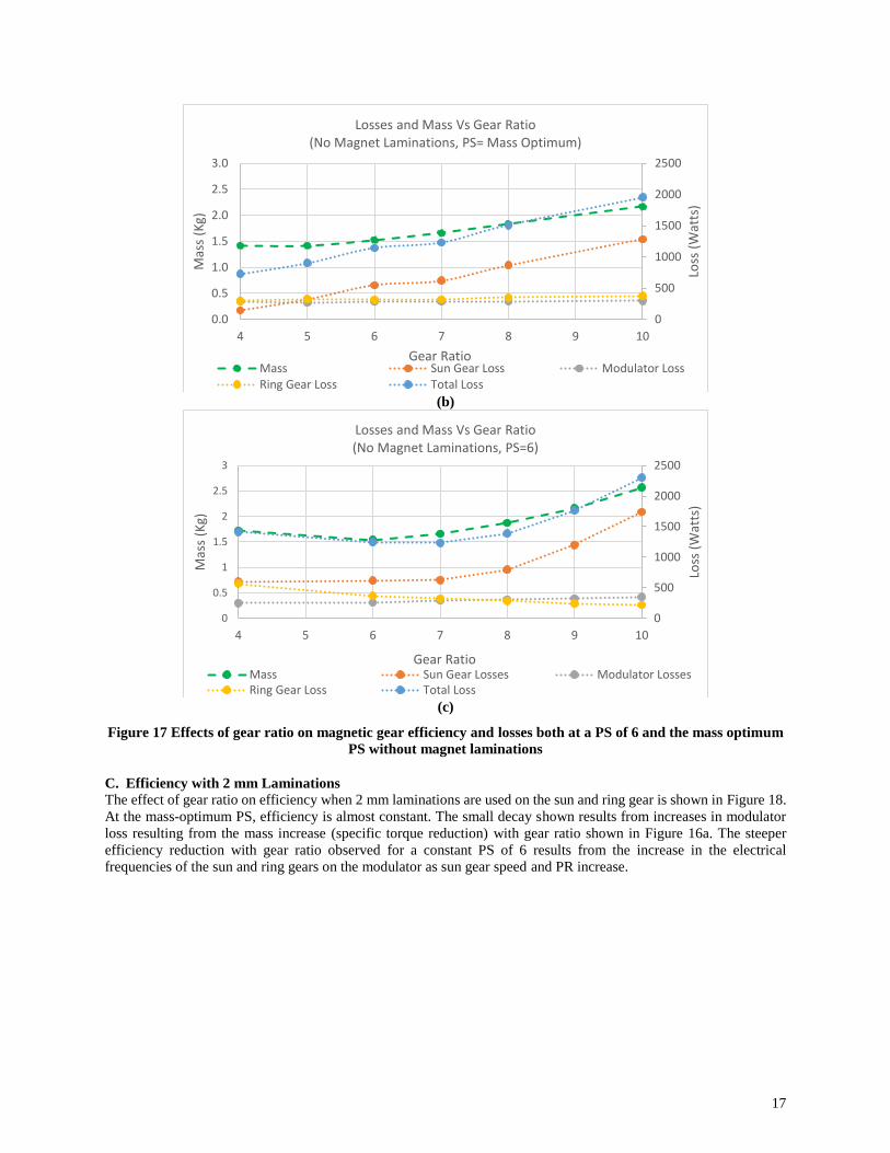
At a constant PS, the electrical frequency of the sun gear on the ring gear and modulator increases with increased
gear ratio, because of the increase in sun gear rotational speed. Modulator losses increase with increased gear ratio as
a result. However, ring gear losses are reduced, because at a constant PS, increasing gear ratio increases TRM and
reduces the ring gear’s magnet width. The sun magnets have essentially a constant width as gear ratio increases at
constant PS, but since PR and sun gear rotation speed both increase with increasing gear ratio at constant PS, the
electrical frequency of the ring gear on the sun gear increases more significantly with increased gear ratio than it did
in the mass-optimum PS case. Additionally, the gear axial length and mass increase more significantly as gear ratio
increases at a constant PS, because PR increases above 32-36 pole pairs and correspondingly ring gear pole-to-pole
leakage and magnetic fill percentage effects become significant (as detailed ins Section VII A). The result is the more
non-linear variation in sun gear magnet losses shown in Figure 17c. Efficiency initially increases with gear ratio, at
constant PS of 6, as the gear axial length and mass are reduced, and then it decreases as the ring gear electrical
frequency on the sun and the gear mass increase.
(a)
95%
96%
97%
98%
99%
100%
4 5 6 7 8 9 10
Effi
cien
cy
Gear Ratio
Efficiency Vs Gear Ratio(No Magnet Laminations)
PS=Mass Optimum
PS=6
17
(b)
(c)
Figure 17 Effects of gear ratio on magnetic gear efficiency and losses both at a PS of 6 and the mass optimum
PS without magnet laminations
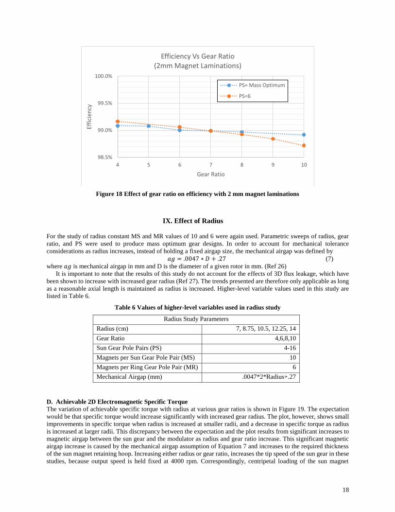
C. Efficiency with 2 mm Laminations
The effect of gear ratio on efficiency when 2 mm laminations are used on the sun and ring gear is shown in Figure 18.
At the mass-optimum PS, efficiency is almost constant. The small decay shown results from increases in modulator
loss resulting from the mass increase (specific torque reduction) with gear ratio shown in Figure 16a. The steeper
efficiency reduction with gear ratio observed for a constant PS of 6 results from the increase in the electrical
frequencies of the sun and ring gears on the modulator as sun gear speed and PR increase.
0
500
1000
1500
2000
2500
0.0
0.5
1.0
1.5
2.0
2.5
3.0
4 5 6 7 8 9 10
Loss
(W
atts
)
Mas
s (K
g)
Gear Ratio
Losses and Mass Vs Gear Ratio(No Magnet Laminations, PS= Mass Optimum)
Mass Sun Gear Loss Modulator LossRing Gear Loss Total Loss
0
500
1000
1500
2000
2500
0
0.5
1
1.5
2
2.5
3
4 5 6 7 8 9 10
Loss
(W
atts
)
Mas
s (K
g)
Gear Ratio
Losses and Mass Vs Gear Ratio(No Magnet Laminations, PS=6)
Mass Sun Gear Losses Modulator LossesRing Gear Loss Total Loss
18
Figure 18 Effect of gear ratio on efficiency with 2 mm magnet laminations
IX. Effect of Radius
For the study of radius constant MS and MR values of 10 and 6 were again used. Parametric sweeps of radius, gear
ratio, and PS were used to produce mass optimum gear designs. In order to account for mechanical tolerance
considerations as radius increases, instead of holding a fixed airgap size, the mechanical airgap was defined by
𝑎𝑔 = .0047 ∗ 𝐷 + .27 (7)
where 𝑎𝑔 is mechanical airgap in mm and D is the diameter of a given rotor in mm. (Ref 26)
It is important to note that the results of this study do not account for the effects of 3D flux leakage, which have
been shown to increase with increased gear radius (Ref 27). The trends presented are therefore only applicable as long
as a reasonable axial length is maintained as radius is increased. Higher-level variable values used in this study are
listed in Table 6.
Table 6 Values of higher-level variables used in radius study
Radius Study Parameters
Radius (cm) 7, 8.75, 10.5, 12.25, 14
Gear Ratio 4,6,8,10
Sun Gear Pole Pairs (PS) 4-16
Magnets per Sun Gear Pole Pair (MS) 10
Magnets per Ring Gear Pole Pair (MR) 6
Mechanical Airgap (mm) .0047*2*Radius+.27
D. Achievable 2D Electromagnetic Specific Torque
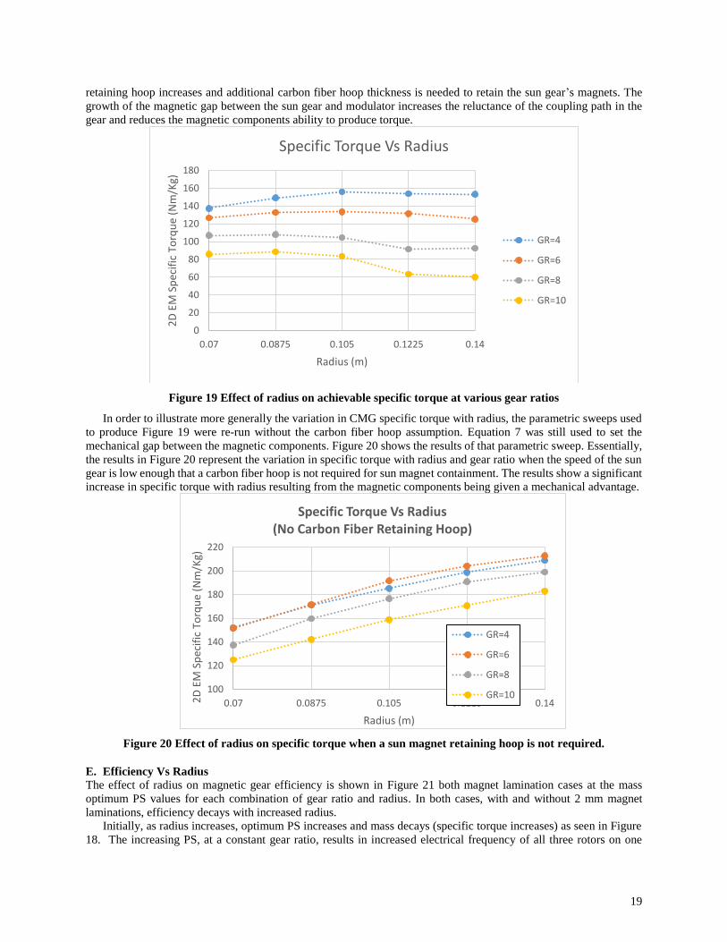
The variation of achievable specific torque with radius at various gear ratios is shown in Figure 19. The expectation
would be that specific torque would increase significantly with increased gear radius. The plot, however, shows small
improvements in specific torque when radius is increased at smaller radii, and a decrease in specific torque as radius
is increased at larger radii. This discrepancy between the expectation and the plot results from significant increases to
magnetic airgap between the sun gear and the modulator as radius and gear ratio increase. This significant magnetic
airgap increase is caused by the mechanical airgap assumption of Equation 7 and increases to the required thickness
of the sun magnet retaining hoop. Increasing either radius or gear ratio, increases the tip speed of the sun gear in these
studies, because output speed is held fixed at 4000 rpm. Correspondingly, centripetal loading of the sun magnet
98.5%
99.0%
99.5%
100.0%
4 5 6 7 8 9 10
Effi
cien
cy
Gear Ratio
Efficiency Vs Gear Ratio(2mm Magnet Laminations)
PS= Mass Optimum
PS=6
19
retaining hoop increases and additional carbon fiber hoop thickness is needed to retain the sun gear’s magnets. The
growth of the magnetic gap between the sun gear and modulator increases the reluctance of the coupling path in the
gear and reduces the magnetic components ability to produce torque.
Figure 19 Effect of radius on achievable specific torque at various gear ratios
In order to illustrate more generally the variation in CMG specific torque with radius, the parametric sweeps used
to produce Figure 19 were re-run without the carbon fiber hoop assumption. Equation 7 was still used to set the
mechanical gap between the magnetic components. Figure 20 shows the results of that parametric sweep. Essentially,
the results in Figure 20 represent the variation in specific torque with radius and gear ratio when the speed of the sun
gear is low enough that a carbon fiber hoop is not required for sun magnet containment. The results show a significant
increase in specific torque with radius resulting from the magnetic components being given a mechanical advantage.
Figure 20 Effect of radius on specific torque when a sun magnet retaining hoop is not required.
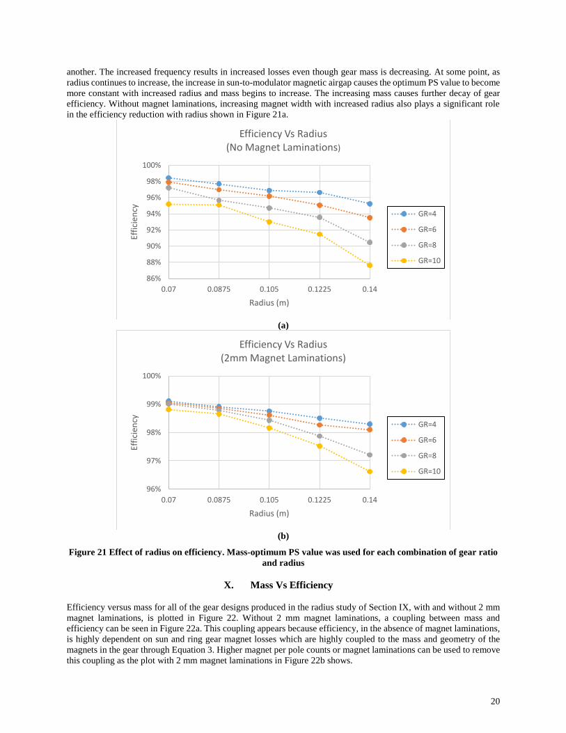
E. Efficiency Vs Radius
The effect of radius on magnetic gear efficiency is shown in Figure 21 both magnet lamination cases at the mass
optimum PS values for each combination of gear ratio and radius. In both cases, with and without 2 mm magnet
laminations, efficiency decays with increased radius.
Initially, as radius increases, optimum PS increases and mass decays (specific torque increases) as seen in Figure
18. The increasing PS, at a constant gear ratio, results in increased electrical frequency of all three rotors on one
0
20
40
60
80
100
120
140
160
180
0.07 0.0875 0.105 0.1225 0.14
2D
EM
Sp
ecif
ic T
orq
ue
(Nm
/Kg)
Radius (m)
Specific Torque Vs Radius
GR=4
GR=6
GR=8
GR=10
100
120
140
160
180
200
220
0.07 0.0875 0.105 0.1225 0.142D
EM
Sp
ecif
ic T
orq
ue
(Nm
/Kg)
Radius (m)
Specific Torque Vs Radius(No Carbon Fiber Retaining Hoop)
GR=4
GR=6
GR=8
GR=10
20
another. The increased frequency results in increased losses even though gear mass is decreasing. At some point, as
radius continues to increase, the increase in sun-to-modulator magnetic airgap causes the optimum PS value to become
more constant with increased radius and mass begins to increase. The increasing mass causes further decay of gear
efficiency. Without magnet laminations, increasing magnet width with increased radius also plays a significant role
in the efficiency reduction with radius shown in Figure 21a.
(a)
(b)
Figure 21 Effect of radius on efficiency. Mass-optimum PS value was used for each combination of gear ratio
and radius
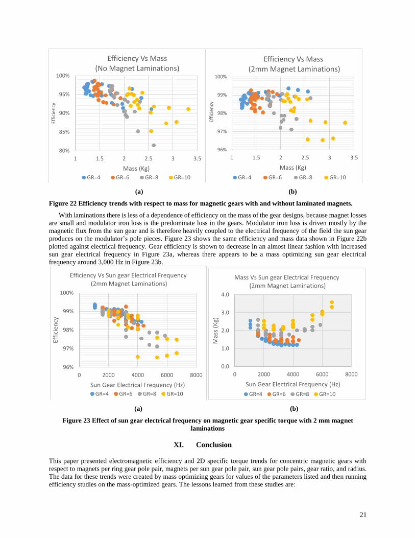
X. Mass Vs Efficiency
Efficiency versus mass for all of the gear designs produced in the radius study of Section IX, with and without 2 mm
magnet laminations, is plotted in Figure 22. Without 2 mm magnet laminations, a coupling between mass and
efficiency can be seen in Figure 22a. This coupling appears because efficiency, in the absence of magnet laminations,
is highly dependent on sun and ring gear magnet losses which are highly coupled to the mass and geometry of the
magnets in the gear through Equation 3. Higher magnet per pole counts or magnet laminations can be used to remove
this coupling as the plot with 2 mm magnet laminations in Figure 22b shows.
86%
88%
90%
92%
94%
96%
98%
100%
0.07 0.0875 0.105 0.1225 0.14
Effi
cien
cy
Radius (m)
Efficiency Vs Radius(No Magnet Laminations)
GR=4
GR=6
GR=8
GR=10
96%
97%
98%
99%
100%
0.07 0.0875 0.105 0.1225 0.14
Effi
cien
cy
Radius (m)
Efficiency Vs Radius(2mm Magnet Laminations)
GR=4
GR=6
GR=8
GR=10
21
(a) (b)
Figure 22 Efficiency trends with respect to mass for magnetic gears with and without laminated magnets.
With laminations there is less of a dependence of efficiency on the mass of the gear designs, because magnet losses
are small and modulator iron loss is the predominate loss in the gears. Modulator iron loss is driven mostly by the
magnetic flux from the sun gear and is therefore heavily coupled to the electrical frequency of the field the sun gear
produces on the modulator’s pole pieces. Figure 23 shows the same efficiency and mass data shown in Figure 22b
plotted against electrical frequency. Gear efficiency is shown to decrease in an almost linear fashion with increased
sun gear electrical frequency in Figure 23a, whereas there appears to be a mass optimizing sun gear electrical
frequency around 3,000 Hz in Figure 23b.
(a) (b)
Figure 23 Effect of sun gear electrical frequency on magnetic gear specific torque with 2 mm magnet
laminations
XI. Conclusion
This paper presented electromagnetic efficiency and 2D specific torque trends for concentric magnetic gears with
respect to magnets per ring gear pole pair, magnets per sun gear pole pair, sun gear pole pairs, gear ratio, and radius.
The data for these trends were created by mass optimizing gears for values of the parameters listed and then running
efficiency studies on the mass-optimized gears. The lessons learned from these studies are:
80%
85%
90%
95%
100%
1 1.5 2 2.5 3 3.5
Effi
cien
cy
Mass (Kg)
Efficiency Vs Mass (No Magnet Laminations)
GR=4 GR=6 GR=8 GR=10
96%
97%
98%
99%
100%
1 1.5 2 2.5 3 3.5
Effi
cien
cy
Mass (Kg)
Efficiency Vs Mass(2mm Magnet Laminations)
GR=4 GR=6 GR=8 GR=10
96%
97%
98%
99%
100%
0 2000 4000 6000 8000
Effi
cien
cy
Sun Gear Electrical Frequency (Hz)
Efficiency Vs Sun gear Electrical Frequency(2mm Magnet Laminations)
GR=4 GR=6 GR=8 GR=10
0.0
1.0
2.0
3.0
4.0
0 2000 4000 6000 8000
Mas
s (K
g)
Sun Gear Electrical Frequency (Hz)
Mass Vs Sun gear Electrical Frequency(2mm Magnet Laminations)
GR=4 GR=6 GR=8 GR=10
22
1. Magnets per pole pair in a Halbach array on either the sun or ring gear improve concentric magnetic gear
specific torque, until significant magnetic fill percentage is lost due to mechanical and manufacturing
considerations. If 100% magnet fill can always be maintained with increased magnet per pole count,
specific torque will always go up with increased magnets per pole count, but with diminishing marginal
returns.
2. High magnet per pole pair count can significantly reduce the eddy current losses in a magnetic gear and
may be an alternative to magnet laminations for enabling high efficiency.
3. At a given radius, gear ratio, and airgap size, there is an optimum number of sun gear pole pairs for
maximizing specific torque. This optimum number is driven by limits on ring gear pole pair count that
result from pole-to-pole flux leakage and magnetic fill percentage loss effects.
4. In the absence of magnet laminations, sun gear losses are the dominate losses in a magnetic gear. Sun gear
losses trend heavily with the dimensions and thereby the mass of the sun gear magnets. Correspondingly
efficiency trends with the mass of the gear.
5. In the presence of magnet laminations, modulator/iron loss is the dominate loss in a magnetic gear.
Modulator loss trends with the electrical frequency of the sun and ring gear on the modulator.
Correspondingly, efficiency trends with the electrical frequency of the sun and ring gear on the modulator.
6. Due to the high speed of the output assumed in this study, the required carbon fiber hoop thickness to retain
the sun gear magnets greatly increased the magnetic airgap between the sun gear and modulator as radius
and/or gear ratio increased. The larger magnetic airgaps resulted in specific torque decaying with gear ratio
and limited specific torque increases with radius.
7. At speeds where a carbon fiber hoop is not required to retain the sun magnets, magnetic gear specific
torque increases nearly linearly with radius.
XII. Appendix
A. Magnet Eddy Current Model
Eddy currents in the magnets were predicted using the eddy current model for general periodic waves found in
Reference 24. The model defines volumetric loss in a component experiencing a periodically varying magnetic field
as
𝑃𝑐 =1
16
𝑉
𝜌
𝑤2𝑙2
𝑤2 + 𝑙
1
𝑇∫ (
𝑑𝐵
𝑑𝑡)2
𝑇
0
𝑑𝑡
Where 𝑃𝑐 is the volumetric loss, w the tangential thickness of the magnet, l is the axial length of a given magnet
section, V is the volume of the magnet, 𝜌 is the resistivity of the material, T is the period of repetition, and B is
magnetic field magnitude.
Using numerical integration this equation can be written
𝑃𝑐 =1
16
𝑉
𝜌
𝑤2𝑙2
𝑤2 + 𝑙
1
∆𝑡 ∗ 𝑁∑(
∆𝐵𝑖
∆𝑡𝑖
)2
𝑁
𝑖=1
∆𝑡𝑖
Where N is the number of time steps and ∆𝑡 is the length of the time step. Because ∆𝑡 is constant this equation can be
simplified to
𝑃𝑐 =1
∆𝑡 2
1
16
𝑉
𝜌
𝑤2𝑙2
𝑤2 + 𝑙
1
𝑁∑ ∆𝐵𝑖
2
𝑁
𝑖=1
B. Pole Piece Iron Loss Model
Modulator loss was predicted using the Improved Generalized Stienmetz Equation (IGSE) with minor loop separation
method found in Reference 25. The IGSE is a modification to the Stienmetz Equation that allows for accurate
prediction of core loss when the magnetic field is not sinusoidal. The Stienmetz Equation defines the specific core
loss (loss per Kg of material) in electrical steel subjected to a sinusoidal varying magnetic field as
𝑃𝑣 = 𝑘 ∗ 𝑓𝛼𝐵𝛽
Where 𝑃𝑣 is specific core loss, 𝑓 is the frequency of the sinusoidal varying magnetic field, 𝐵 is the peak value of the
field, and 𝑘, 𝛼, and 𝛽 are material constants. 𝑘, 𝛼, and 𝛽 can generally be determined from core loss information
23
provided by electrical steel manufacturers. The IGSE uses these parameters to predict core loss for non-sinusoidal
waves as
𝑃𝑣 =1
𝑇∫ 𝑘1 |
𝑑𝐵
𝑑𝑡|
𝛼
(∆𝐵)𝛽−𝛼𝑑𝑡𝑇
0
𝑘1 =𝑘
2𝛽−1𝜋𝛼−1 ∫ |cos (𝜃)|𝛼𝑑𝜃2𝜋
0
Where 𝑇 is the period of repetition of the field, ∆𝐵 is the peak to peak flux density, and 𝑘1is an updated loss coefficient.
The algorithm for numerically implementing this equation with minor loop separation is discussed in detail in
Reference 25. This algorithm was implemented on the magnetic field vs rotor position data from the finite element
simulation. By a similar method as used for the magnet loss, modulator loss can also be written
𝐿𝑜𝑠𝑠𝑚𝑜𝑑 = 𝐶𝑚𝑜𝑑 ∗1
∆𝑡
𝛼
Where 𝐿𝑜𝑠𝑠𝑚𝑜𝑑 is the modulator losses and 𝐶𝑚𝑜𝑑 is the modulator loss coefficient.
This loss prediction is only meant to serve as a min baseline for modulator loss in the gear as the IGSE most likely
under predicts the losses. The IGSE is only accurate for unidirectional fields and therefore it doesn’t account for the
losses from the rotating fields (Ref 28). Iron loss is the most likely location that additionally losses need to be added
based on the thermal behavior and efficiency testing of the gear
XIII. Acknowledgments
The authors would like to acknowledge NASA’s Revolutionary Vertical Lift Technologies (RVLT) and
Independent Research and Development (IRAD) projects for funding this work.
XIV. References
1. Anderson, A.D., Renner, N.J., Wang, Y., Lee, D., Agrawal, S., Sirimanna, S., Haran, K., Banerjee, A.,
Starr, M., and Felder, J., “System Weight Comparison of Electric Machine Topologies for Electric Aircraft
Propulsion” 2018 AIAA/IEEE Electric Aircraft Technologies Symposium. Cincinnati, Ohio.
2. Zhang, X., Bowman, C. L., O’Connell, T. C., and Haran, K. S., “Large electric machines for aircraft
electric propulsion,” IET Electric Power Applications, vol. 12, issue 6, 2018.
3. Borisavljevic, A., “Limits, Modeling, and Design of High-Speed Permanent Magnet Machnines,” ISBN
978-3-642-33457-3, Springer 2013
4. Astridge, D., and Savage, M., “Rotorcraft Drivetrain Life Safety and Reliability,” AGARD Report No. 775,
North Atlantic Treaty Organization Advisory Group For Aerospace Research And Development, June 1990
5. Zaretsky, E. V., “Bearing and Gear Steels for Aerospace Applications” NASA Technical Memorandum
102529, NASA, March 1990
6. Desvaux, M., Bildstein, H., Sire, S., and Fasquelle, A., “Magnetic Losses and Thermal Analysis in a
Magnetic Gear for Wind Turbine,” 13th International Conference on Ecological Vehicles and Renewable
Energies, IEEE, 2018
7. Johnson, M., Gardner, M.C., Toliyat, H. A., Englebretson, S., Ouyan, W., and Tschida, C., “Design,
Construction, and Analysis of a Large-Scale Inner Stator Radial Flux Magnetically Geared Generator for
Wave Energy Conversion,” IEEE Transactions on Industrial Applications Vol 50 No 4, July/August 2018
8. McGilton, B., Crozier, R., McDonal, A., and Mueller, M., “Review of Magnetic Gear Technologies and
Their Applications in Marine Energy,” IET Renewable Power Generation Conference, IET, December
2017
9. Frandsen, T.v., Rasmussen P.O., and Jensen K.K., “Improved Motor Integrated Permanent Magnet Gear for
Traction Applications,” 2012 IEEE Energy Conversion Congress and Exposition (ECCE)
24
10. Jian, L., Chau, K.T., and Jian, J.Z., “ An Integrated Magnetic-Geared Permanent-Magnet In-Wheel Motor
Drive for Electric Vehicles,” IEEE Vehicle Power and Propulsion Conference, IEE, September 3-5, 2008
11. Jansen, R., Brown, G. V., Felder, J. L., and Duffy, K. P., “Turboelectric Aircraft Drive Key Performance
Parameters and Functional Requirements,” American Institute of Aeronautics and Astronautics, 2015
12. Kirsten P. Duffy and Ralph Jansen. "Partially Turboelectric and Hybrid Electric Aircraft Drive Key
Performance Parameters", 2018 AIAA/IEEE Electric Aircraft Technologies Symposium, AIAA Propulsion
and Energy Forum, (AIAA 2018-5023)
13. Asnani, V., Scheidler, J., and Tallerico, T., “Magnetic gearing research at NASA,” Proc. of AHS Int. 74 th
Annual Forum, Phoenix, AZ, May 14-17, 2018.
14. Scheidler, J. J., Asnani, V. M., and Tallerico, T. F., “NASA’s magnetic gearing research for electrified
aircraft propulsion,” Proc. of AIAA/IEEE Electric Aircraft Technologies Symposium, Cincinnati, OH, Aug
21-22, 2018.
15. Scheidler, J.J., Cameron, Z. A., and Tallerico, T. F., “Dynamic Testing of a High Specific Torque
Concentric Magnetic Gear,” Proc. of the Vertical Flight Society’s 75th Annual Forum, Philadelphia, PA,
May 13-16, 2019
16. Cameron, Z. A., Tallerico, T. F, and Scheidler, J.J. “Lessons Learned in Fabrication of a High-Specific-
Torque Magnetic Gear,” Proc. of the Vertical Flight Society’s 75th Annual Forum, Philadelphia, PA, May
13-16, 2019
17. Gardner, M.C., Johnson, M., and Toliyat, H. A., “Comparison of Surface Permanent Magnet Axial and
Radial Flux Coaxial Magnetic Gears,” IEEE Transactions on Energy Conversion, 2018
18. Johnson, M., Gardner, M.C., and Toliyat, H. A., “Design Comparison of NbFeB and Ferrite Radial Flux
Surface Permanent Magnet Coaxial Magnetic Gears,” IEEE Transactions on Industrial Applications
Volume 54 Issue 2, IEEE, October 2017
19. Johnson, M., Gardner, M.C., and Toliyat, H. A., "Analysis of High Gear Ratio Capabilities for Single-
Stage, Series Multistage, and Compound Differential Coaxial Magnetic Gears," in IEEE Transactions on
Energy Conversion, vol. 34, no. 2, pp. 665-672, June 2019.
20. Li, X., Chau, K. T., Cheng, M., and Hau, W., “Comparison of Magnetic Geared Permanent Magnet
Machines” Progress in Electromagnetics Research Vol 133 pg 177-198, 2013
21. Atallah, K., Calverley, S., and Howe, D., “Design, analysis and realization of a high-performance magnetic
gear,” Proc. of IEEE Electric Power Applications, p. 135-143, 2004.
22. Zhu, Z.Q., and Howe, D.: ‘Influence of design parameters on cogging torque in permanent magnet
machines’, IEEE Trans. Magn., 2000, 15, (5), pp. 407–412
23. Jungmayr, G., Loeffler, J., Winter, B., Jeske, F., and Amrhein, W., “Magnetic gear: radial force, cogging
torque, skewing, and optimization,” IEEE Transactions on Industry Applications, p. 3822-3830, 2016.
24. Rouho, S., Santa-Nokki, T., Kolehmainen, J., and Arkkio, A., “Modeling Magnet Length in 2-D Finite
Element Analysis of Electric Machine,” IEEE Transactions on Magnetic Vol 45 No 8, IEEE, August 2009
25. K. Venkatachalam, C. Sullivan, T. Abdallah, and H. Tacca, “Accurate prediction of ferrite core loss with
non-sinusoidal waveforms using only Steinmetz parameters,” in Computers in Power Electronics, 2002.
Proceedings. 2002 IEEE Workshop on, June 2002, pp. 36 – 41
25
26. Duan, Y. and Ionel, D.M., "Nonlinear Scaling Rules for Brushless PM Synchronous Machines Based on
Optimal Design Studies for a Wide Range of Power Ratings," in IEEE Transactions on Industry
Applications, vol. 50, no. 2, pp. 1044-1052, March-April 2014.
27. Gerber, S. and Wang, R-J., “Analysis of the end-effects in magnetic gears and magnetically geared
machines,” 2014 International Conference on Electrical Machines Proceedings, Berlin, German, pp. 396 –
402, Nov. 2014.
28. Krings, “Iron Losses in electrical Machines – Influence of Material Properties, Manufacturing Processes,
and Inverter Operation” Doctoral Thesis KTH University. Stockholm, Sweden 2014