Embed Size (px)
Citation preview

Electromagnetic energy harvesting using
magnetic levitation architectures: a review
Pedro Carneiro a, Marco P. Soares dos Santos a,b,c,∗,
André Rodrigues a, Jorge A. F. Ferreira a,b, José A. O. Simões a,b,
A. Torres Marques c,d, Andrei L. Kholkin e,f,g
aDepartment of Mechanical Engineering, University of Aveiro, Aveiro, Portugal.
bCentre for Mechanical Technology & Automation (TEMA), University of Aveiro,
Aveiro, Portugal.
cAssociated Laboratory for Energy, Transports and Aeronautics (LAETA), Porto,
Portugal
dMechanical Engineering Department, University of Porto, Porto, Portugal.
eDepartment of Physics, University of Aveiro, Aveiro, Portugal.
fCICECO - Aveiro Institute of Materials, Aveiro, Portugal.
gLaboratory of Functional Low-Dimensional Structures, National University of
Science and Technology MISIS, Moscow, Russia.
Preprint submitted to Elsevier 15 November 2019

Abstract
Motion-driven electromagnetic energy harvesters have the ability to provide
low-cost and customizable electric powering. They are a well-suited technological
solution to autonomously supply a broad range of high-sophisticated devices. This
paper presents a detailed review focused on major breakthroughs in the scope
of electromagnetic energy harvesting using magnetic levitation architectures. A
rigorous analysis of twenty-one design congurations was made to compare their
geometric and constructive parameters, optimization methodologies and energy
harvesting performances. This review also explores the most relevant models
(analytical, semi-analytical, empirical and nite element method) already developed
to make intelligible the physical phenomena of their transduction mechanisms. The
most relevant approaches to model each physical phenomenon of these transduction
mechanisms are highlighted in this paper. Very good agreements were found between
experimental and simulation tests with deviations lower than 15%. Moreover,
the external motion excitations and electric energy harvesting outputs were also
comprehensively compared and critically discussed. Electric power densities up to 8
mW/cm3 (8 kW/m3) have already been achieved; for resistive loads, the maximum
voltage and current were 43.4 V and 150 mA, respectively, for volumes up to 235
cm3. Results highlight the potential of these harvesters to convert mechanical energy
into electric energy both for large-scale and small-scale applications. Moreover,
this paper proposes future research directions towards eciency maximization and
minimization of energy production costs.
Key words: Energy harvesting, Self-powering, Electromagnetic harvesting,
Magnetic levitation, Modelling, Design optimization
∗ Corresponding author.
Email address: [email protected] (Marco P. Soares dos Santos).
2
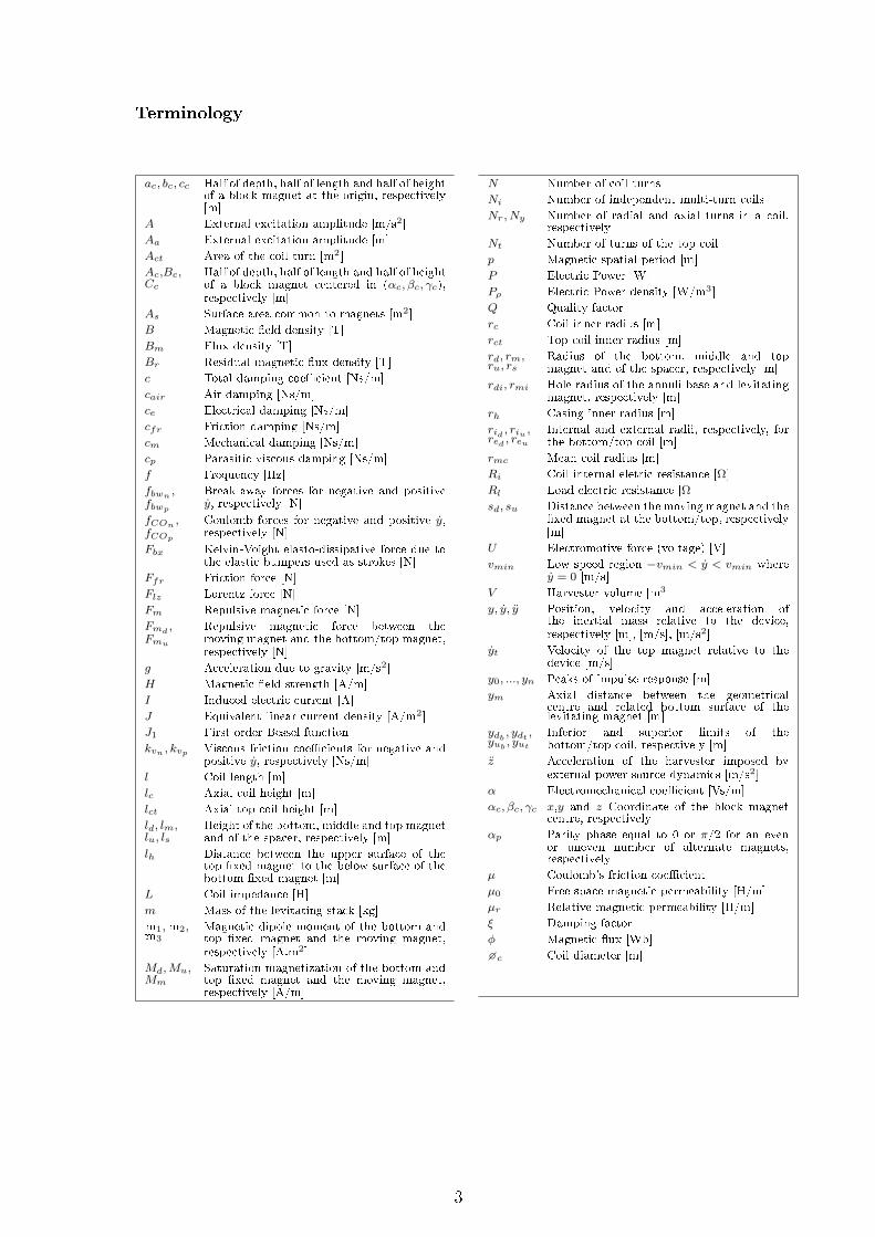
Terminology
ac, bc, cc Half of depth, half of length and half of heightof a block magnet at the origin, respectively[m]
A External excitation amplitude [m/s2]
Aa External excitation amplitude [m]
Act Area of the coil turn [m2]
Ac,Bc,Cc
Half of depth, half of length and half of heightof a block magnet centered in (αc, βc, γc),respectively [m]
As Surface area common to magnets [m2]
B Magnetic eld density [T]
Bm Flux density [T]
Br Residual magnetic ux density [T]
c Total damping coecient [Ns/m]
cair Air damping [Ns/m]
ce Electrical damping [Ns/m]
cfr Friction damping [Ns/m]
cm Mechanical damping [Ns/m]
cp Parasitic viscous damping [Ns/m]
f Frequency [Hz]
fbwn ,fbwp
Break-away forces for negative and positivey, respectively [N]
fCOn ,fCOp
Coulomb forces for negative and positive y,respectively [N]
Fbx Kelvin-Voight elasto-dissipative force due tothe elastic bumpers used as strokes [N]
Ffr Friction force [N]
Flz Lorentz force [N]
Fm Repulsive magnetic force [N]
Fmd ,Fmu
Repulsive magnetic force between themoving magnet and the bottom/top magnet,respectively [N]
g Acceleration due to gravity [m/s2]
H Magnetic eld strength [A/m]
I Induced electric current [A]
J Equivalent linear current density [A/m2]
J1 First order Bessel function
kvn , kvp Viscous friction coecients for negative andpositive y, respectively [Ns/m]
l Coil length [m]
lc Axial coil height [m]
lct Axial top coil height [m]
ld, lm,lu, ls
Height of the bottom, middle and top magnetand of the spacer, respectively [m]
lh Distance between the upper surface of thetop xed magnet to the below surface of thebottom xed magnet [m]
L Coil impedance [H]
m Mass of the levitating stack [kg]
m1,m2,m3
Magnetic dipole moment of the bottom andtop xed magnet and the moving magnet,respectively [A.m2]
Md,Mu,Mm
Saturation magnetization of the bottom andtop xed magnet and the moving magnet,respectively [A/m]
N Number of coil turns
Ni Number of independent multi-turn coils
Nr, Ny Number of radial and axial turns in a coil,respectively
Nt Number of turns of the top coil
p Magnetic spatial period [m]
P Electric Power [W]
Pρ Electric Power density [W/m3]
Q Quality factor
rc Coil inner radius [m]
rct Top coil inner radius [m]
rd, rm,ru, rs
Radius of the bottom, middle and topmagnet and of the spacer, respectively [m]
rdi, rmi Hole radius of the annuli base and levitatingmagnet, respectively [m]
rh Casing inner radius [m]
rid , riu ,red , reuInternal and external radii, respectively, forthe bottom/top coil [m]
rmc Mean coil radius [m]
Ri Coil internal eletric resistance [Ω]
Rl Load electric resistance [Ω]
sd, su Distance between the moving magnet and thexed magnet at the bottom/top, respectively[m]
U Electromotive force (voltage) [V]
vmin Low speed region −vmin < y < vmin wherey = 0 [m/s]
V Harvester volume [m3]
y, y, y Position, velocity and acceleration ofthe inertial mass relative to the device,respectively [m], [m/s], [m/s2]
yt Velocity of the top magnet relative to thedevice [m/s]
y0, ..., yn Peaks of impulse response [m]
ym Axial distance between the geometricalcentre and related bottom surface of thelevitating magnet [m]
ydb , ydt ,yub , yutInferior and superior limits of thebottom/top coil, respectively [m]
z Acceleration of the harvester imposed byexternal power source dynamics [m/s2]
α Electromechanical coecient [Vs/m]
αc, βc, γc x,y and z Coordinate of the block magnetcentre, respectively
αp Parity phase equal to 0 or π/2 for an evenor uneven number of alternate magnets,respectively
µ Coulomb's friction coecient
µ0 Free space magnetic permeability [H/m]
µr Relative magnetic permeability [H/m]
ξ Damping factor
φ Magnetic ux [Wb]
c Coil diameter [m]
3

1 Introduction
Scientic breakthroughs in electric energy harvesting are of utmost importance for
technological sophistication in many societal domains [17]. Energy harvesting from
environment is becoming increasingly a promising methodology to power both large-scale
and small-scale devices. These require ecient and customizable self-powering technologies
to operate throughout long periods of time with reduced intermittence and high transduction
rate, ensuring low production and maintenance costs, as well as performance adaptability for
circumstantial variations in the dynamics of primary power sources [810].
Common renewable sources for large-scale electric powering, such as wind and sun, are
intermittent, which result in complex grid managements and high energy production costs.
The latter occurs mainly due to the backup costs to support the uctuating electrical energy
production, such as costs related to conversion processes and energy storage [1115]. However,
current non-intermittent renewable energy systems, including those harvesting electric energy
from the ocean, require complex mechanical systems for energy transduction, such as
turbines, oleo-hydraulic systems, transmission systems, etc., which bear high maintenance
costs and signicant performance losses. Besides, they are not able to ensure performance
adaptation to varying motion-driven vibrations [16,17]. Therefore, there is a need to develop
advanced technological solutions to highly improve the performance of non-intermittent
clean energy harvesting systems. Research in this area is mandatory as the electricity
consumption is estimated to increase around 55% worldwide by 2040, and the European
Union already established goals to reduce conventional non-renewable energy sources by
80-95% up to 2050 [18,19]. Signicant growth has also been observed in the development
of self-powering small-scale power systems. Such an ability has been recognized as critical
for emerging technologies to develop high-performance autonomous remote sensors [20,21],
wearable devices [2224], implantable biomedical devices [22,23,25] and mobile applications
[26], among many others [27]. Most of these technologies must have their own incorporated
power supply to ensure that enough energy is available, but also to reduce problems related
to interconnection, electronic noise and control system complexity [13,28]. Nonetheless, at the
moment, current harvesting solutions to power these multifunctional devices electrically do
4

not full existing requirements for eective self-powering, including enough electric current
magnitudes, long-term operation, low maintenance costs, reduced performance losses and
ability to adapt to excitation variations [25,29,30]. The use of batteries is far behind the
power requirements of innovative stand-alone technologies, as they have limited capacity
to store energy or their replacement is impractical or inconvenient [31]. In the scope of
implantable medical devices, the limited service time of batteries exposes patients to surgical
procedures and other potential risks that must be avoided. Besides, around 20% of bioelectronic
medical devices failures, with possible catastrophic impacts on patients, are directly related
to their electric power supply systems [32]. In contrast, advanced multifunctional medical
devices need the incorporation of intracorporeal energy harvesting systems to ensure: (i)
continuous and long-lasting acquisition of multiple monitoring bio-signals [33]; (ii) continuous
and long-lasting therapy based on electromechanical actuation and/or biophysical stimulation
[3436]; (iii) processing capability to run intensive closed-loop dynamic control algorithms and
complex articial intelligence procedures [37,38]; (iv) frequent communication operations to
extracorporeal systems, allowing clinicians to control and monitor medical devices [3941].
As mechanical energy surrounding us is available [4244], transduction mechanisms based on
electromagnetic [4547], piezoelectric [4850], electrostatic [5153] and triboelectric [5456]
principles have been extensively studied to convert mechanical energy into electric energy.
This paper is focused on electromagnetic energy harvesting systems using magnetic levitation
architectures. These are recent and promising self-powering technologies because they have
the potential to implement high-performance energy harvesting for a wide range of devices,
both for small-scale and large-scale self-powering [33,5759], since they present distinctive
properties like their non-complex design (which avoids the use of complex mechanical systems
for energy conversion), low maintenance requirements and ability to operate autonomously
with stable performance for long periods of time [25,33,60]. Several studies report that the
magnitude of harvested energy is strongly dependent on geometric optimization prior to
fabrication [25,6163]. Moreover, their eectiveness have been investigated for applications
involving severe dimensional constraints and time-varying power source dynamics. Although
several architectures using magnetic levitation have already been proposed, research has been
mainly conducted in the scope from mono-stable to multi-stable architectures (bi-stable,
5

tri-stable and quad-stable harvesters) [25,45,58]. Multi-stable approaches require wider
structures and additional magnets. Their nonlinearities are more prominent than the highly
nonlinear behaviors observed in mono-stable architectures. As a consequence, multi-stable
architectures demand much more complex optimization methods, which in turn demand
much greater computational costs. Despite all scientic ndings in this eld, the highest
performances that mono-stable and multi-stable harvesters are able to achieve are currently
unknown. To date, no exhaustive and systematic eort has been done to compare harvester
designs, optimization methods, harvested electric power, and modelling and validation
of the transduction mechanisms of electromagnetic energy harvesting systems comprising
mono-stable magnetic levitation architectures. This review presents all relevant studies that
report the major achievements in this scientic area. The ultimate goal is to contribute towards
the implementation of highly-sophisticated electromagnetic energy harvesters with ability to
supply energy to a wide range of stand-alone devices.
2 Methods
2.1 Selection criteria
In this paper we present a rigorous analysis of electromagnetic harvesters focused on magnetic
levitation architectures that full four major requirements:
(1) Architectures must comprise two or more magnets, and one or more coils;
(2) Architectures including at least one xed hard-magnetic element, and one or more
hard-magnetic elements experiencing magnetic levitation;
(3) Architectures designed for axial motions of the levitating magnet(s) within the container;
(4) Architectures with mono-stable electromagnetic-induction congurations. Multi-stable
congurations were considered outside the scope of this review.
The search was completed in September 2019. Twenty-nine relevant papers were selected
according to these criteria.
6

2.2 Literature search strategy
The following data were extracted and analysed from the selected papers: (1) architectures
proposed by each author; (2) the most relevant geometrical and construction parameters used
to characterize each harvester, namely the geometry of the hollow container, coil(s) design,
specications of the hard-magnetic elements, including the levitating magnet(s); (3) dierent
approaches to model each physical phenomenon of the transduction mechanisms of energy
harvesters: the magnetic eld produced by the hard magnetic elements, repulsive magnetic
forces, induced voltages, electric currents, electromechanical coupling coecients and damping
forces; (4) agreement between the simulation and experimental tests; (5) electric output,
namely power, voltage and current, as well as the excitation patterns and resistive loads used
for model validation purposes; (6) approaches for design optimization.
2.3 Assessment of other literature reviews
To our knowledge, four review papers were published on the scope of electromagnetic energy
harvesting from vibration sources that refer to research ndings obtained using magnetic
levitation architectures. Harb [3] only reports the working principle of a single magnetic spring
generator (proposed by Saha et al. [64]) and its ability to harvest energy during human-induced
motion. Wei and Jing [65] presented a review that includes theory, modelling methods and
validation of piezoelectric, electromagnetic and electrostatic harvesters, but only mentioned
the research ndings of Mann and Sims [66] and the ability of magnetic levitation harvesters
to operate in a wide range of vibration frequencies. The review paper published by Yildirim et
al. [67] describes only the study of Mann and Sims [66], without carrying out an exhaustive and
comprehensive analysis to the overall architectures already proposed in the literature. Siddique
et al. [5] only refer a study whose architecture comprises magnetic levitation [68], but the
energy transduction mechanism includes the piezoelectric principle. Therefore, no review that
presents major breakthroughs achieved on the scope of magnetic levitation architectures has
been published so far. Neither comparative nor critical analyses have been done highlighting the
design congurations, construction parameters, energy outputs and modelling of transduction
mechanisms.
7

3 Design congurations
3.1 Magnetic levitation architectures
The basic architecture of these energy harvesters comprises a hollow cylindrical container,
three permanent magnets and a coil, as illustrated in Fig. 1a. The polarity of the magnets is
arranged in a way that the levitating magnet experiences a repulsive force due to the xed
magnets, which are attached to the end extremities of the container. A portion of the container
is wrapped in a multilayer coil around its outer surface [25]. Twenty-one design congurations
were already tested using: (i) circular or rectangular containers [66,69]; (ii) cylindrical, ring
or block magnets [7072]; (iii) number of levitating magnets up to six [7]; (iv) number of
coil windings up to ve [73]; (v) planar or helicoidal coils [74,75]; (vi) levitating magnets
with and without guidance systems [6,57]; (vii) levitating magnets in stack arrangements with
or without spacers [61,64], and experiencing repulsive or attractive forces [76,77]; (viii) end
extremities of containers with xed permanent magnets or, dierently, with springs or bumpers
[78,79]; (ix) nonlinear FR4 planar spring anchored to the casing and glued to the top magnet,
guiding its motion (use of dual-mass) [80]. According to the number of coils and permanent
magnets, these twenty-one designs can be categorized as: (i) single coil and single levitating
magnet: 3 congurations (Fig. 1a-c) [25,70,72]; (ii) single coil and multiple levitating magnets: 8
congurations (Fig. 2a-h) [7,13,57,64,76,77,81]; (iii) multiple coils and single levitating magnet:
5 congurations (Fig. 3a-e) [66,78,79,82,80]; (iv) multiple coils and multiple levitating magnets:
5 congurations (Fig. 4a-e) [6,73,75,77,83].
The rst category is presented in twelve studies [25,61,6972,74,8488]. They designed circular
(Fig. 1a,b) and rectangular containers (Fig. 1c) with a helicoidal coil around each outer
surface; cylindrical (Fig. 1a), ring (Fig. 1b) and block magnets (Fig. 1c) were used; not only
the basic positioning of the xed magnets was studied (Fig. 1a,b), but also a conguration
in which two xed magnets were mounted in only one end cap of the device (Fig. 1c);
guidance systems were also considered (Fig. 1b). When a single coil and multiple levitating
magnets are incorporated (second category), seven studies [7,13,57,64,76,77,81] present only
circular containers, used cylindrical (Fig. 2a-g) and ring magnets (Fig. 2h), counting up to six
levitating magnets (Fig. 2g), with (Fig. 2b-e,h) and without spacers (Fig. 2a,f,g), in which the
8

inertial magnets experienced both repulsive (Fig. 2c-f,h) or attractive forces (Fig. 2a-c,f,g). Two
architectures utilize the behaviour of levitating magnets only using a xed magnet (Fig. 2c,d);
and another one was engineered with a guidance system (Fig. 2h). For harvesters embedding a
single levitating magnet inside the container and attaching multiple coils (third category), six
studies [66,78,79,82,89,80] propose cylindrical containers that include cylindrical (Fig. 3a-c,e)
and ring magnets arranged along a shaft (Fig. 3d). These were arranged according to the
basic architecture (Fig. 3a,d), or only with a xed permanent magnet (Fig. 3b,c) or with a
design that uses dual inertial mass (Fig. 3e). Two helicoidal coil windings were wrapped in
all congurations, included one whose wire is wounded both inside and outside the annular
permanent magnet to engineer both the inner and outer coils (Fig. 3d). Some harvesters were
designed using the inertial magnet coupled to a spring (Fig. 3b) or two rubber bumpers bonded
to the upper and lower lids (Fig. 3c). Besides, new designs were proposed in which the top
magnet is freed and a FR4 mechanical spring is used to guide its motion (Fig. 3e). Finally, ve
studies [6,73,75,77,83] included up to ve helicoidal (Fig. 4b) and sixteen planar coils (Fig. 4e),
up to four stack magnets (Fig. 4c), and levitating magnets shaped as cylindrical (Fig. 4a-c),
ring (Fig. 4d) and planar (2x5 block array) (Fig. 4e). Besides, the analysis was extended to
architectures composed by guidance systems (Fig. 4d), and those in which the inertial mass is
disposed so that the same poles are facing each other (Fig. 4a-d) with (Fig. 4a-c) and without
spacers (Fig. 4d).
3.2 Construction parameters of magnetic levitation harvesters
The most relevant construction parameters that characterize each harvester are shown in Table
1 and illustrated in Fig. 5. Comparison includes geometric and volumetric data from the
container and coil properties. The analysed harvesters have container lengths from 20 to 254
mm and respective inner radii between 2.2 and 28.6 mm. The harvesters' stroke has lengths
from 13 to 184 mm, although most of them did not exceed 50 mm. Such dimensions correlate
with volumes ranging from 0.5 to 235 cm3, even though most harvesters were designed to
exhibit volumes smaller than 17 cm3. Hence, it is noteworthy to state that no harvesters were
already designed for large-scale electric powering. In a signicant number of studies (6 out
9

of 29) [25,72,76,79,81,89], the authors selected PTFE polytetrauorethylene (TEFLON®) to
manufacture the container, as this material features low friction coecients.
Energy harvesting was observed considering coils designed to take up approximately from 10
to 50% of the harvester lengths. As expected, higher induced voltages in the coil terminals are
obtained for smaller distances between the inner coil radius and the levitating stack radius;
nevertheless, researchers dened these distances in the range from 0.5 to 9 mm, most likely
to avoid problems related to the mechanical integrity of the harvesters, or to minimize the
complexity of the manufacturing process. A signicant range of coil resistances (2.4 - 6191 Ω)
and inductances (2.9×10⁻³ - 1.5 H) were also imposed due to the wide range in the number of
coil turns (240 - 15000) and copper wire diameters (40 - 635 µm), as shown in Table 1. Notice
that 23 out of 29 authors did not report the coil(s) inductance, disregarding their inuence
on the electric dynamics of the transduction mechanisms. Importantly, several authors (9) did
not mention the coil(s) resistance, although it must be indicated as it is required to maximize
the self-powering ability according to the maximum power transfer theorem.
The features related to levitating and xed magnets strongly inuence both mechanical and
electric dynamics of energy harvesters (as highlighted in section 4.4) [71]. Therefore, detailed
data concerning properties of the magnets chosen by each author, namely their mass, geometry
(Fig. 5) and magnetization are also reported in Table 2. The inertial mass always includes
levitating magnets that vary from 1.2 to 1.54×10³ g. Neodymium magnets were chosen by
all authors, since they are able to provide strong magnetic uxes through the coils (up to
N45 grade) and ensure a stable magnetic moment during long periods of time. A remarkable
amount of studies (22 out of 29) included congurations with cylindrical hard magnets, but
ring (4 out of 29) and block (3 out of 29) geometries were also explored.
10

Table 1
Geometrical and constructive parameters(a)
ReferencesContainer Coil
Figure(b)
lh[mm]
rh[mm]
sd + su[mm]
V[cm3]
lc[mm]
rc[mm]
N[turns]
c[µm]
Ri[Ω]
L[H]
Category
1
Constantinou,Mellor,
Wilcox[84]65.4 ND 27.3 ≈40 ND 18.9 476 360 ND 0.01 Fig.1(b)
Constantinou,Mellor, Wilcox[70]
70.4 ND 32.3 ND ND 18.9 240 600 2.4 0.0029 Fig.1(b)
Bernal, García[74] ND ND ND ND 1000 ND ND ND ND ND Fig.1(a)
Foisal, Hong,Chung [71](c)
44/46 3.5 26-30 ND 5 4 1500 ND ND ND Fig.1(a)
Foisal, Lee, Chung[85]
46 3.5 28 ≈7.4 5 4 1500 100 96.5 ND Fig.1(a)
Foisal, Chung[86]
48 3.5 32 ≈7.4 5 4 1500 100 96.1 ND Fig.1(a)
Berdy, Valentino,Peroulis [69]
35 NA(d) ≈20.7 7.7 4 NA(e) 1000 635 450 ND Fig.1(c)
Berdy, Valentino,Peroulis [72]
35 NA(d) ≈20.7 7.7 4 NA(e) 1000 635 450 ND Fig.1(c)
Liu et al. [87] 46-66 3.5 36-56 4.4-6.3 10-30 5.5 ND 200 10-20 ND Fig.1(a)
Santos et al. [25] 58 3.1 50 ≈12 20 4.1 15000 68 3630 1 Fig.1(a)
Kecik et al. [61] ND ND ND ND ND ND ND ND 2300(f) 1.5 Fig.1(a)
K¦cik [88] ND ND ND ND ND ND ND ND 1200 1.5 Fig.1(a)
Category
2
Saha et al. [64] ≈55 ND≈34/35
12.7 6 8.5 1000 40 800 ND Fig.2(b,c)-A
Dallago, Marchesi,Venchi [76]
≈56 7.5 ≈38 ≈13 ND ND 500 110 60 ND Fig.2(a)-A
Munaz, Lee,Chung [13]
≈80 5.5 ≈35 9 5 6 1000 ND 115 ND Fig.2(f)-R
Masoumi, Wang[57]
254 28.6 101.6 ≈235 101.6 31.2 10186 143 6191 ND Fig.2(h)-R
Wang et al. [7]≈144/204
10.3≈112-184
≈ 71/100
60 12.5 480 500 5 ND Fig.2(f,g)-A
Pancharoen, Zhu,Beeby [81]
≈20 2.2 ≈13 ≈0.5 ND 2.5 1100 50 236 ND Fig.2(e)-R
Struwig,Wolhuter, Niesler
[77]
111.8-121
5.593.8-95
15.1-15.7
6-13 6.5280-607
127 14-31 ND Fig.2(c,d)-R
Category
3
Mann, Sims [66] ND ND 72.6 ND ND ND ND ND 188 ND Fig.3(a)
Bonisoli et al. [78] ND ND ND ND ND ND ND ND ND ND Fig.3(c)
Morais et al. [79] ND 3.3 ND 3.8 24 ND 9600 63 ND ND Fig.3(b)
Morgado et
al.[89]78.5 ND 49.5 ≈16 26 5 10000 ND ND ND Fig.3(a)
Yang et al. [82] 28 ND 16 ND ND 15(g) 2×600 ND ND ND Fig.3(d)
Aldawood,(h)
Nguyen,Bardaweel [80]
100.8 6.6 72.2 ≈220 13.7 8.7 450 80 ≈93 ND Fig.3(e)
Category
4
Saravia, Ramírez,Gatti [6]
≈110 8 ≈65 ≈74 ND 10.3 1850 240 ND ND Fig.4(c)-R
Geisler et al.
[73](i)50 4.3 32 9 5×5 4.9 5×2800 57 5×950 ND Fig.4(b)-R
Apo, Priya [83] ND 5.3 ND 6.2 9.6 5.5 5600 44 2800 ND Fig.4(d)-R
Zhang, Wang,Kim [75]
200 ND ND 120 NA NA 16(j) ND ND ND Fig.4(e)
Struwig,Wolhuter, Niesler
[77]120.7 5.5 102.7 16.8 19.4 6.5 910 127 46 ND Fig.4(a)-R
(a) Terminology: NA - not applicable; ND - not dened.(b) Magnet interaction of the inertial stack: A-attracting; R-repelling.(c) This paper studied 2 congurations, each with an array of four dierent generators. Their parameters are presented
individually.(d) ≈ 3.5×25.7.(e) ≈ 6.8×29.(f) Ri +Rl(g) Wires were wounded both inside and outside of the annular permanent magnet. The radii of the inner coils (inside
and outside) are 3.5 and 4.5 mm.(h) Top coil parameters: lct=12.7 mm; rct=26.7 mm; Nt=1500 turns; Ri ≈890 Ω.(i) Coils winding are considered as independent.(j) Number of planar coils wounded over the boundaries between the magnets of the 2×5 magnet array.
11

Table 2
Features of levitating and xed magnets(a)
References
Nr.
(b)
magnets
m [g]Dimensions [mm] Sat. magnetization [kA/m]
rm×lm ru×lu rd×ld rs×ls Mm Mu Md
Category
1
Constantinou,Mellor,
Wilcox[84]
1
38 12.7/6×12.7 12.7/ND×12.7 NA (N38)
Constantinou,Mellor, Wilcox[70]
38 12.7/6×12.7 NA (N38)
Bernal, García[74] ND 6.5×5 ND ND NA 1.15×10³ ND ND
Foisal, Hong,Chung [71]
2.5-3.4
3×163×123×143×16
1.5×11×21×21×2
0.5×11×21×2
1.5×2
NA (N35)
Foisal, Lee, Chung[85]
2.9 3×14 1×2 NA (N35)
Foisal, Chung[86]
2.93 3×14 0.5×1 1×2 NA (N35)
Berdy, Valentino,Peroulis [69] 7.7 NA(c) NA NA(d) NA (N42)
Berdy, Valentino,Peroulis [72]
Liu et al. [87] 1.2 3×6 1.5×2 NA 860 (N35)
Santos et al. [25] 1.2 3×6 3×1 NA 800 761 761
Kecik et al. [61] 98 ND ND ND NA ND
K¦cik [88] 90 ND ND ND NA ND
Category
2
Saha et al. [64] 2 27 7.5×8 5×1 7.5×3 ND
Dallago, Marchesi,Venchi [76]
2 20.9 7.5×8 5×1 NA ND
Munaz, Lee,Chung [13]
3 11.5 5×10 5×5 5×10 NA ND
Masoumi, Wang[57]
3 1539 25.4/3.2×25.4 25.4/3.2×12.7 1.03×10³ (N42)
Wang et al. [7] 3/631.5/63
10×4 NA 890 (N35)
Pancharoen, Zhu,Beeby [81]
2 ND 2×1 2×NDi 868 (N35)
Struwig,Wolhuter, Niesler
[77]2/3 ND 5×5 NA 5×5 5×3 (N35)
Category
3
Mann, Sims [66]
1
19.5 ND ND ND NA ND
Bonisoli et al. [78] ND ND NA ND NA ND
Morais et al. [79] 4.4 3×24 NA 2×2 NA (N42)
Morgado et
al.[89]9.5 4×24 2×2 3×3 NA ND
Yang et al. [82] 29 12/5×10 12/5×1 NA ND
Aldawood,Nguyen,
Bardaweel [80]18.1 6.4
×19.1 6.4×4.8 NA (N42)
Category
4 Saravia, Ramírez,Gatti [6]
4 48 7.5×5 (N37)
Geisler et al. [73] 3 5.7 4×4 1×1 2×1 3.5×2 (N45)
Apo, Priya [83] 3 22.4 4.8/1.6×4.8 3.2×0.8 NA (N42)
Zhang, Wang,Kim [75]
10 40 6.4×ND×3.2 NA ND NA ND
(a) Terminology: NA - not applicable; ND - not dened.(b) Number of inertial magnets.(c) 25.4×3.18×12.7.(d) 3.18×3.18×1.6.
12

4 Review of transduction mechanisms models
4.1 Overall analysis of modelling approaches
The interest in modelling transduction mechanisms of electromagnetic harvesters with
magnetic levitation architectures emerges from the need and complexity to design them highly
ecient. It is true that the amount of mechanical energy surrounding us, which is ready to
be transduced into electricity, is signicant [8,9]. Nevertheless, their performance optimization
is problematic because: (i) geometric optimization prior to fabrication is hard to carry out
as these harvesters present highly non-linear behaviour [25]; (ii) architecture adaptability is
required to eectively address the issue of unknown, broadband and time-varying behaviour
of mechanical power sources [70]; (iii) dimensional constraints must be considered for practical
usability [69,77]. Modelling the energy transduction is then mandatory to ensure their superior
performance over other motion-driven harvesters [25].
Twenty-nine dierent models were developed to intelligibly describe the most relevant
physical phenomena occurring on the twenty-one proposed design congurations (Table 3).
Most authors focused on modelling the magnetic eld from levitating magnets, repulsive
magnetic forces between permanent magnets, induced electromotive force from the relative
motion between coil and levitating magnet(s), electric current, electromechanical coupling
coecient, mechanical friction and damping forces, as presented in Table 3. The overall
dynamic behaviour of the energy transduction systems, which includes mechanical and
electric dynamics, was always modelled by time-dependent ordinary dierential equations.
Four modelling approaches were distinguished to model each physical phenomenon: (i)
empirical, which is based on parametric equations that t experimental data; (ii) analytical,
focused on physical laws, comprising parameters with physical meaning, to explain physical
mechanisms under experimental observation; (iii) semi-analytical, established as a set of
analytic approximations to describe the same physical mechanisms; (iv) and nite element
method (FEM), a numerical technique used to perform nite element analysis (FEA) of
a physical phenomenon. Almost all authors conducted hybridizations; dierently, Bonisoli
et al. [78] and Foisal et al. [71] developed purely analytical models. Six hybrid patterns
13

were established, all of these including some type of analytical modelling, three comprising
semi-analytical modelling, three with FEM modelling, and, surprisingly, three studies used
empirical models (Table 3). The most common encloses three modelling approaches: the
analytical-empirical-FEM pattern, counting with eight models [6,7,57,64,76,77,81,83], was
the most considered one; however, the analytical-semi-analytical-empirical [69,70,72,89] and
analytical-semi-analytical-FEM [13,73,75,82] hybridizations were also frequently used. Besides,
three hybrid patterns were proposed using two modelling approaches: analytical-empirical
[61,66,79,87,88], analytical-FEM [74,85,86] and analytical-semi-analytical [25,84]. These
ndings reveal that numerical analysis is more often used than analytical analysis and
emphasize: (i) lower computational eciency for optimization purposes, since it requires
suitable identication of many parameters related to the design of coil(s), container and
magnet(s); (ii) overall energy transduction mechanisms remain partially unclear. Nevertheless,
even though only a qualitative evaluation of the accuracy of the models was carried out,
very good approximations were achieved both for electric and mechanical dynamics (Table
3). It is noteworthy to recognize the results achieved by Mann and Sims [66], Constantinoub
et al. [70], Berdy et al. [72], Soares dos Santos et al. [25] and Wang et al. [7]. Although
few studies reported quantitative analyses, simulation-experiment agreements with deviations
lower than 15% and 16% for voltage and power harvesting, respectively, as well as 5.2% for the
inertial motion of levitating magnets have already been obtained (Table 3) [7,72,81]. About
half of the studies (14 out of 29) did not report an overall electric or mechanical model
validation. Concerning model validation related to the overall mechanical dynamics, Mann
and Sims [66] were the only authors that investigated the inertial magnet dynamics; all the
remaining authors studied the harvester resonant frequency under open circuit conditions
[64,69,72,81,84]. The experimental validation of the magnetic eld was only observed in three
studies; more signicantly, the repulsive magnetic forces and induced voltage were validated
by eleven and nine studies, respectively [66,73,72]. Of all studies assessed, only Constantinou
et al. [70] and Kecik et al. [61] obtained a good match between measured and calculated
electromagnetic coupling coecients. So far, the electric current, damping coecients and
forces were not validated. Furthermore, no modelling approaches under tri-dimensional motions
were validated up to date. Only two-dimensional analyses were carried out on the scope of
magnetic levitation architectures. In the next sections we describe how authors modelled the
14

most relevant physical phenomena of the transduction mechanisms of these harvesters. Due
to the signicant number of models analysed and considering the impossibility to present all
simulation results, we provide the ones of one of the most signicant studies that reported a
very good simulation-experiment agreement (Fig. 6) [25].
Table 3
Overall analysis of the modulation approaches(a)
References
Magnetic
eld
Repulsive
magnetic
force
Induced
voltage
Electric
current
Coupling
coe.
Damping
coe./forces
Overall modelvalidation
Model validationrelated to eachphenomenon
Category
1
Constantinou,Mellor,
Wilcox[84]ND SA/A A A SA ND
Electric: ND;mechanical: resonantfrequencies with
average error of 1.6%for 3 dierent lh.
MF: ND; RMF: ND; V:good approximation (OC);I: ND: CC: ND; DF: ND.
Constantinou,Mellor, Wilcox[70]
SASA/
A/EA A SA A/E
Electric: power (2.1g,37 Hz, ∆Rl) presentsslight dierences;mechanical: ND.
MF: ND; RMF: goodapproximation; V: ND; I:
ND; CC goodapproximation: ND; DF:
ND.
Bernal, García[74] AA/
FEMA A NA A ND
MF: good approximation;RMF: ND; V: ND; I: ND;
DF: ND.
Foisal, Hong,Chung [71]
A A A ND A A ND ND
Foisal, Lee,Chung [85]
FEM ND A ND NA ND ND ND
Foisal, Chung[86]
FEM A ND ND NA ND NDMF: ND; RMF: ND; V:considerable dierences(OC); I: ND; DF: ND.
Berdy, Valentino,Peroulis [69]
A A A A SA A/E
Electric: power withvery good agreement(0.1g/0.075g, ∆Rl);mechanical: resonantfrequency (0.05g)presents an error of
≈3%.
MF: ND; RMF: ND; V:ringdown test accuratelycorrelated (OC); I: ND;
CC: ND; DF: ND.
Berdy, Valentino,Peroulis [72]
A A A A SA A/E
Electric: averagepower was predictedwithin 14% accuracyerrors; mechanical:resonant frequencywith errors of 4.48%,4.54% and 5.17% forvertical apparatusesusing rotations of 15°
and 30°.
MF: ND; RMF: ND; V:ringdown tests (OC) forthe 3 developed devices
under dierent apparatus,as well as under
customized excitation(Rl=1000 W, ∆f) exhibitvery good agreement; I:ND; CC: ND; DF: ND.
Liu et al. [87] A A A A A A/E ND
MF: ND; RMF: ND; V:errors between 3.7% and20% (0.5g-0.65g, 4.2-4.8Hz); I: ND; CC: ND; DF:
ND.
Santos et al. [25] SA SA SA A NA A/SA
Electric: meanabsolute percentageerror of 6.02% andcross-correlationshigher than 86%;mechanical: ND.
ND
15

Table 3
Continuation
References
Magnetic
eld
Repulsive
magnetic
force
Induced
voltage
Electric
current
Coupling
coe.
Damping
coe./forces
Overall modelvalidation
Model validationrelated to eachphenomenon
Category
1
Kecik et al. [61] ND E/A A A E/A E ND
MF: ND; RMF: goodapproximation; V: ND; I:
ND; CC: very goodapproximation; DF: ND.
K¦cik [88] ND E/A A A E E NDMF: ND; RMF: good
approximation; V: ND; I:ND; CC: ND; DF: ND.
Category
2
Saha et al. [64] FEMFEM/
AA ND ND A/E
Electric: ND;mechanical: resonant
frequency (OC,0.039g) presents an 5%
error.
MF: ND; RMF: very goodapproximation; V: ND; I:ND; CC: ND; DF: ND.
Dallago, Marchesi,Venchi [76]
FEMFEM/
AA A A A/E
Electric: the inducedvoltage (1g, 9/10.4 Hz,
∆Rl) presentsmaximum error:20/80% withoutLorentz force and
(7/6%) considering theLorentz force;
mechanical: ND.
MF: ND; RMF: goodapproximation; V: peakvoltage with an averageerror of 10.4% (1g, 7-12Hz); I: ND; CC: ND; DF:
ND.
Munaz, Lee,Chung [13]
SA/
FEMND A ND NA ND ND
MF: ND; RMF: ND; V:RMS OC voltage (0.5g, 6Hz) error is 5.7%; I: ND:
DF: ND.
Masoumi, Wang[57]
FEM E/A A ND A A/E NDMF: ND; RMF: very goodapproximation; V: ND; I:ND; CC: ND; DF: ND.
Wang et al. [7] FEM E/A A A ND A/E
Electric: voltageresponse for forwardfreq. sweeps point outmaximum relative
errors lower than 15%while the response forreverse freq. sweeps
shows slightdierences compared
to simulations;mechanical: ND.
MF: ND; RMF: goodapproximation; V: ND; I:ND; CC: ND; DF: ND.
Pancharoen, Zhu,Beeby [81]
A/
FEM
A/
FEMA ND A A/E
Electric: power error(0.5g) lower than 16%;mechanical: resonantfrequency (0.5g)
presents errors lowerthan 2.3%.
MF: errors between 0.5%and 14.6%; RMF: goodapproximation; V: OCvoltage with errors lowerthan 8.5%; I: ND; CC:ND; DF: ND. Height ofthe quiescent positionwith errors in the range
10.3 - 21.1%.
Struwig,Wolhuter, Niesler
[77]ND
A/
FEM
A/
FEMA NA E ND
MF: ND; RMF: very goodapproximation; V: ND; I:
ND; DF: ND.
Category
3
Mann, Sims [66] ND E/A A A A A/E
Electric: ND;mechanical: for
excitation that causedhysteresis, the highest
velocities of themiddle magnet werenot achievable (the
remainingexperimental data
matched the analyticalsolution).
MF: ND; RMF: very goodapproximation; V: ND; I:ND; CC: ND; DF: ND.
Bonisoli et al. [78] ND ND A A A A
Electric: power andinduced voltage werewell approximated;mechanical: ND.
ND
16

Table 3
Continuation
References
Magnetic
eld
Repulsive
magnetic
force
Induced
voltage
Electric
current
Coupling
coe.
Damping
coe./forces
Overall modelvalidation
Model validationrelated to eachphenomenon
Category
3
Morais et al. [79] E A A ND A A/E
Electric: power andinduced voltage
(0.09g-0.55g, 0.75-1.85Hz, ∆Rl) exhibitslight dierences;mechanical: ND.
ND
Morgado et
al.[89]SA SA A ND NA E ND
MF: ND; RMF: ND; V:OC free fall test from aheight of 15 mm showsgood agreement with
simulation results; I: ND;DF: ND.
Yang et al. [82] FEM A SA ND NA ND ND ND
Aldawood,Nguyen,
Bardaweel [80]A
SA
FEMSA ND NA ND
Electric: ND;mechanical: forward
and backwardfrequency responses(OC, 0.3g/0.5g, 5-15
Hz) were wellapproximated.
MF: ND; RMF: goodapproximation; V: verygood approximation; I:
ND; DF: ND.
Category
4 Saravia, RamírezGatti [6]
FEM E/A A A A A/E
Electric: power andinduced voltage (1g,Rl=100 W, ∆f) werewell approximated;mechanical: ND.
MF: ND; RMF: very goodapproximation; V: ND; I:ND; CC: ND; DF: ND.
Geisler et al. [73] FEM SA A A NA A
Electric: power (1g,Rl=950 W, ∆f) waswell approximated;mechanical: ND.
MF: good approximation;RMF: ND; V: ND; I: ND;
DF: ND.
Apo, Priya [83] FEM A A A A A/E ND ND
Zhang, Wang,Kim [75]
SA/
FEMA A ND NA A ND ND
(a) Terminology: NA - not applicable; ND - not dened; NV - non validated; A - analytical; SA - semi-analytical;E - empirical; FEM - Finite Element Mfethod; MF - magnetic eld; RMF - repulsive magnetic force; V - induced
voltage;I - electric current; CC - coupling coecient; DF - damping coecients/forces; ∆var - variable dened in a specicrange.
4.2 Modelling the inertial mass dynamics
The overall dynamic behaviour of energy transduction systems, that include mechanical and
electric dynamics, has always been modelled by time-dependent ordinary dierential equations.
Table 4 summarizes the governing equations that express the mechanical dynamics of the
motion-driven inertial mass, which can comprise levitating magnets and spacers in between.
All authors modelled this dynamics using the Newton's second law as a result of a sum of forces
along one degree of freedom, usually the vertical direction, although some inclinations were also
imposed, and horizontal tests were also carried out [7,72]. Most models include the eects due
to the inertia force of the moving magnet(s)-spacer(s), the damping coecient, the repulsive
17

(levitation) force between the moving mass and the xed magnets, and the gravitational force.
A couple of studies detailed the damping coecient as a combined eect of both electrical
and mechanical damping [7,57,66,79,87]. Some authors modelled the electrical damping with
an electromechanical coupling coecient (as described in Table 9), but more complex models
considered the Lorentz force to include the magnetic force opposing the inertial motion of the
levitating magnet(s) caused by the electric current owing through the coil(s) [25,74]. A system
reduction to a Dung oscillator under both static and dynamic loads was also proposed by
modelling the repulsive forces between magnets as a polynomial function (as explored in Table
6) [66]. Although the Runge-Kutta method was used by some authors to numerically compute
the inertial mass dynamics [6,80], most studies did not clarify which numerical method were
used to compute the proposed models.
Table 4
Mechanical dynamics of inertial masses
Equations References
−mz = my + cy + Fm [7,13,57,64,71,73,77,79,84,85,87]
−mz = my + cy + Fm +mg [6,61,66,70,75,76,81,83,86,88,89,80]
−mz = my + (ce + cp)y + Ffr − Fm +mg [69,72]
mz = −my + Flz − Ffr + Fm [74]
−mz = my + Flz + Ffr + Fm +mg [25]
−F = −my + Ffr + Fbx + Fm [78]
4.3 Modelling the magnetic eld of permanent magnets
The magnetic eld (B) variation is required to drive the mechanical-electric transduction
mechanism. It was modelled by analytical, semi-analytical and FEM approaches. Three
dierent methods have been proposed to model this phenomenon (Table 5): (i) B is constant
along the tri-dimensional space enclosed by the harvester, not computed using the magnet
characteristics (equation Q1) [66,79] or computed by analytic approximations (equation Q2)
[71,87]; (ii) B as a single variable function dened on a set of axial distances to the centre
of the levitating hard-magnet (equations Q3 and Q5) [69,72,81]; and (iii) B described as
18

a two-variable function of radial and axial distances to the centre of the levitating magnet
(equations Q6 to Q9) [25,70,74,89].
Researchers who simulate the behaviour of this physical phenomenon by FEM used ANSIS 2D
[13,83,85,86], COMSOL Multiphysics [73,75,81], Finite Element Method Magnetics [6,57], Flux
2D [76] and ANSOFT Maxwell [7]. Two studies did not specify the software [64,82] and some
did not describe how the models were designed, namely their domains, electric and magnetic
properties of materials, 3D mesh characterization and convergence test analyses. Apo and
Priya [83] reported the use of 96 mesh elements.
Foisal et al. [71] studied this phenomenon based on the vector potential model, which in turn
is based on the molecular current approach as the magnetization vector is assumed to be in
line with the axial direction. They characterized the model by subdividing the magnetic eld
in four domains and used them to compute an overall mathematical expression that relates
the coil inner radius with the levitating magnet radius and length (equation Q2). The model
proposed by Liu et al. [87] is quite similar to the previously mentioned study (Q2), but it
was obtained by the line-charge model. Additionally, Pancharoen et al. [81] estimated the
magnetic ux density produced by a cylindrical magnet using a technique that calculates the
magnetic eld of the whole magnet integrating, over its volume, the contributions from the
innitesimal dipoles, and relates the radius and length of the levitating magnet as presented
by equation Q3. Identically to equation Q3, Aldawood et al. [80] were the only researchers
that approached this phenomenon along the longitudinal axis by adopting the magnetic dipole
moment of the levitating magnet (equation Q4). Berdy et al. [69,72] studied the interaction
between two parallelepiped magnets using analytical calculations based on the Coulombian or
equivalent charge model. They considered two charged parallel surfaces carrying two distinct
densities to infer the interaction energy and integrated the result into four spatial domains
(equation Q5). Constantinou et al. [70] modelled this phenomenon as the superposition of the
magnetic eld from two equivalent current sheets representing the outer and inner surfaces of
the ring magnet, as considered in equation Q6. Morgado et al. [89] modelled the magnetic eld
based on the principle that a cylindrical permanent magnet (axially polarized) creates a similar
magnetic eld when an electric current ows through a thin wall solenoid of same diameter
and height with constant current density. Equation Q7 is presented in cylindrical coordinates
19

and exposes the sum of the magnetic eld through every cylindrical current sheets of each
coil (the number of turns, their length and thickness are considered). Bernal and García [74]
considered the magnetostatic problems with cylindrical symmetry and modelled the magnetic
potential using Bessel functions (equation Q8). Finally, Soares dos Santos et al. [25] used the
equivalent surface current model that discretizes the magnet into a nite set of current loop
elements and then superimposed the resultant magnetic eld of each layer (equation Q9). Fig.
6a illustrates how the magnetic eld behaves in the tri-dimensional Cartesian space according
to the model proposed by Soares dos Santos et al. [25].
Table 5
Equations of magnetic eld
Equations References
Q1 B =cte [66,79]
Q2 B =Br2
[rc−rm+lm√rm2+(rc−rm)2
− rc−rm√rm2+(rc−rm)2
][71,87]
Q3B(y) =
Br2
[y+lm√
(y+lm)2+rm2− y√
y2+rm2
]Br ≈ µ0H
[81]
Q4 B(y) =m1µ0
2πrm2lm
(lm−2y√
4rm2+(lm−2y)2+
lm+2y√4rm2+(lm+2y)2
)[80]
Q5B =
1∑i=0
1∑j=0
1∑k=0
(−1)i+j+kMm4πµ0
arctan
[(x−xi)(y−yi)(z−zk)Γijk
]Γijk =
√(x− xi)2 + (y − yi)2 + (z − zi)2
[69,72]
Q6B = ∇×Am
Am−p(rp, yp) =∫ yp+lm
yp−lm(Aout−t(rp, y) + Ain−t(rp, y))dy
[70]
Q7
B(y, r) = 2π∫ (
Nulu(reu−riu )
reu∫riu
yut∫yub
rAϕ(y, r)dydr − Ndld(red
−rid )
red∫rid
ydt∫ydb
rAϕ(y, r)dydr)rdr
Aϕ(y, r) =Mm
2
√rmr
[σk
(k2+h2−h2k2
h2k2 K(k2)− 1k2 E(k2) + h2−1
h2 Π(h2|k2)
)σ+
σ−
]h2 =
4rmr
(rm+r)2; k2 =
4rmr
(rm+r)2+σ2 ; σ± = y ∓ lm2; [F (σ)]σ+
σ− = F (σ+)− F (σ−)
K(s) =∫ π
2
0
1√1−s sin2(θ)
dθ; E(s) =∫ π
2
0
√1− s sin2(θ)dθ; Π(s|t) =
∫ π2
0
1
(1−s sin2 θ)
√1−t sin2 θ
dθ
[89]
Q8B(r, y) = µMy(r, y − ym) +
µMmrm2
∞∫0
(e−k|y−ym−lm| − sign(y − ym)sign(y − ym − lm)e−k|y−ym|)J1(krm)J0(kr)dk
M(z) = My(z)y = Mm∏
(r; rm)∏
(y, lm)y
[74]
Q9
B(y, r) = µ0Mm2π
z+y+lm/2∫z+y−lm/2
f(y, y)[Zt(y, y)E(k) +K(k)]dy
E(k) =∫ π
2
0
√1− k2sin2(φ)dφ; K(k) =
∫ π2
0
1√1−k2sin2(φ)
dφ; f(y, y) = 1√(rh+r)2+(y−y)2
k =
√rh4r
(rh+r)2+(y−y)2; Zt =
r2h−r2−(y−y)2
(rh−r)2+(y−y)2
[25]
20
4.4 Modelling the repulsive magnetic force
The total repulsive magnetic force is given by the sum of the repulsive magnitude forces that
keep the inertial magnetic mass in levitation. It can be computed by the sum of the repulsive
forces of the top and bottom xed magnets (Fig. 1a,b; Fig. 2a,b,e-h; Fig. 3a,d; Fig. 4b-d). All
developed models are illustrated in Table 6. The restoring force and, therefore, the resonance
frequency of the system, can be adjusted by changing the inertial mass, the stroke, the grade of
the permanent magnets or by incorporating xed magnets only in one end cap of the container
(instead of using magnets at both ends). Most studies (19 out of 29) computed the force as a
function of the positioning of the inertial magnet(s) by searching the polynomial coecients
of power series by curve tting (equations Q10 to Q13). This phenomenon was analytically
analysed [13,71,79,80,82,83,8587] or combining: (i) empirical-analytical techniques tting
with experimental measurements [6,7,57,61,66,88]; (ii) FEM-analytical techniques tting with
numeric results [64,76,81]; and (iii) semi-analytical-analytical techniques, using the Ampère's
force law [70,84]. Equation Q14 analytically describes the magnetic force relating the saturation
magnetization of the top, moving and bottom magnets, and the distances between the
moving and xed magnets [71,87]. Zhang et al. [75] approached this phenomenon for small
vibrations near to the initial position of the inertial mass, as described by equation Q15, which
was obtained by tting with values obtained by numerical simulation. The analytical-FEM
approach proposed by Struwig et al. [77] (equation Q16) was established by creating a modied
version of Coulomb's law by introducing a parameter to better approximate the curve for small
motions of the levitating magnet(s). A constant parameter showing a second order relationship
with magnetization was formulated by Pancharoen et al. [81] to model the bottom repulsive
force (equation Q17). Yang et al. [82] conducted a study of this phenomenon taking into
consideration the air-gap ux, the permeance between the moving and xed magnets, and the
principle of continuity (equation Q18). The described formulation proposed in equation Q19
by Apo and Priya [83] relates magnetization with height of the magnets, surface area common
to both magnets and distance between top and levitating hard-magnetic elements. The authors
that proposed equations Q14, Q17, Q18 and Q19 did not provide the deduction method for
their mathematical formulations. Constantinou et al. [70,84] estimated this parameter between
two annular magnets by determining the forces between equivalent current sheets using the
21

Ampère's law of force (equation Q20). The force between two permanent rectangular magnets
was also modelled using the Coulomb model, which consider an equivalent magnetic charge
density on their surfaces (equation Q21) [69,72]. Morgado et al. [89] modelled this phenomenon
combining the Coulomb approach and the Amperian current model (equation Q22). Equation
Q23 was deduced by Aldawood et al. [80] by approximating the levitated magnet as three
dipoles. The total magnetic force acting on the levitated magnet was computed as the gradient
of the dot product between the surrounding magnets' magnetic eld and the levitated magnet's
dipole moment. The semi-analytical approaches using the rst order Bessel function (equations
Q24 and Q25), illustrated by Fig. 6b, were deduced from the derivation of the interaction energy
between magnets, assuming their relative positions and considering the magnetization, radius,
height and distance separating them [25,73,74].
Similarly to the previous section, most researchers who used FEM did not describe how the
models were designed. They only refer that the following softwares were used: COMSOL
Multiphysics [74,81], Flux 2D [76] and ANSIS 2D [83] (two studies did not report which
softwares were used [64,77]). The exceptions were Bernal and García [74], who used 214992
mesh elements and obtained convergence errors around 50%, as well as Apo and Priya [83]
who developed computational models only using 236 mesh elements.
4.5 Modelling the electromotive force
The mechanical energy is converted into electrical energy when the magnetic eld changes
through the coil, inducing an electromotive force (EMF). Most authors focused their
analyses on the analytical methodology to model this physical phenomenon. Hereupon, the
equations to model the EMF are detailed in Table 7. The EMF is mainly described by the
induction Faraday's law, as modelled by equation Q26 [6,7,13,64,69], or as a function of the
electromechanical coupling coecient and velocity of the levitating magnet(s), as highlighted
by the equation Q27 [61,66,70]. The mathematical formulation Q28, proposed by Zhang et al.
[75], is based on the Faraday's law and depends on the acceleration amplitude, mass of the
levitating arrangement, total damping coecient and time-rate change of the magnetic ux.
The open-circuit output voltage was modelled by Pancharoen et al. [81] (equation Q29) as
22
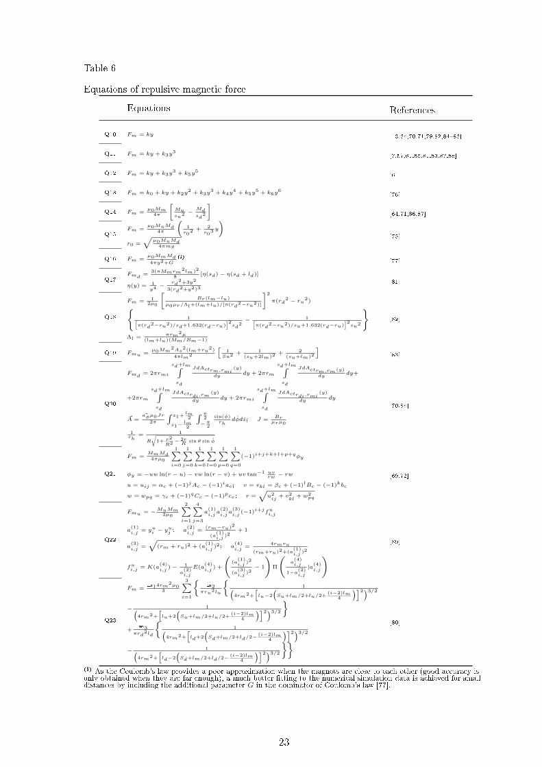
Table 6
Equations of repulsive magnetic force
Equations References
Q10 Fm = ky [13,64,70,71,79,82,8486]
Q11 Fm = ky + k3y3
[7,57,61,66,81,83,87,88]
Q12 Fm = ky + k3y3 + k5y
5[6]
Q13 Fm = k0 + ky + k2y2 + k3y
3 + k4y4 + k5y
5 + k6y6
[76]
Q14 Fm =µ0Mm
4π
[Musu2 −
Mdsd
2
][64,71,86,87]
Q15Fm =
µ0MuMd4π
(1r0
2 + 2r0
3 y
)r0 =
õ0MuMd
4πmg
[75]
Q16 Fm =µ0MmMd4πy2+G
(i)[77]
Q17Fmd =
3(πMmrm2lm)2
8[η(sd)− η(sd + ld)]
η(y) = 1y4 −
rd2+3y2
3(rd2+y2)3
[81]
Q18
Fm = 12µ0
[Br(lm−lu)
µ0µr/Λl+(lm+lu)/[π(rd2−ru2)]
]2
π(rd2 − ru2)
1[π(rd
2−ru2)/sd+1.632(rd−ru)]2sd
2− 1[
π(rd2−ru2)/su+1.632(rd−ru)
]2su2
Λl =
πrm2µ
(lm+lu)(Mm/Bm−1)
[82]
Q19 Fmu =µ0Mm
2As2(lm+ru
2)
4πlm2
[1Su2 + 1
(su+2lm)2+ 2
(su+lm)2
][83]
Q20
Fmd = 2πrmi
sd+lm∫sd
JdActrm,rmi(y)
dydy + 2πrm
sd+lm∫sd
JdActrm,rm (y)
dydy+
+2πrm
sd+lm∫sd
JdActrdi,rm(y)
dydy + 2πrmi
sd+lm∫sd
JdActrdi,rmi(y)
dydy
~A =~aφµ0Jr
2π
∫ z1+lm2
z1−lm2
∫ π2
−π2
sin(φ)rh
dφdz; J =Brµrµ0
1rh
= 1
R
√1+ r2
R2 −2rR
sin θ sin φ
[70,84]
Q21
Fm =MmMd4πµ0
1∑i=0
1∑j=0
1∑k=0
1∑l=0
1∑p=0
1∑q=0
(−1)i+j+k+l+p+qφy
φy = −uw ln(r − u)− vw ln(r − v) + uv tan−1 uvrw− rw
u = uij = αc + (−1)jAc − (−1)iac; v = vkl = βc + (−1)lBc − (−1)kbc
w = wpq = γc + (−1)qCc − (−1)pcc; r =√
u2ij
+ v2kl
+ w2pq
[69,72]
Q22
Fmu = −MuMm2µ0
2∑i=1
4∑j=3
a(1)i,ja
(2)i,ja
(3)i,j
(−1)i+jfui,j
a(1)i,j
= yui − yuj ; a
(2)i,j
=(rm−ru)2
(a(1)i,j
)2+ 1
a(3)i,j
=
√(rm + ru)2 + (a
(1)i,j
)2; a(4)i,j
=4rmru
(rm+ru)2+(a(1)i,j
)2
fui,j = K(a(4)i,j
)− 1
a(2)i,j
E(a(4)i,j
) +
((a
(1)i,j
)2
(a(3)i,j
)2− 1
)Π
(a(4)i,j
1−a(2)i,j
|a(4)i,j
) [89]
Q23
Fm =m14rm
2µ03
3∑i=1
m2
πru2lu
1(
4rm2+
[lu−2
(Su+lm/2+lu/2+
(i−2)lm4
)]2)3/2
− 1(4rm2+
[lu+2
(Su+lm/2+lu/2+
(i−2)lm4
)]2)3/2
+
m3πrd
2ld
1(
4rm2+
[ld+2
(Sd+lm/2+ld/2− (i−2)lm
4
)]2)3/2
− 1(4rm2+
[ld−2
(Sd+lm/2+ld/2− (i−2)lm
4
)]2)3/2
[80]
(i) As the Coulomb's law provides a poor approximation when the magnets are close to each other (good accuracy isonly obtained when they are far enough), a much better tting to the numerical simulation data is achieved for smalldistances by including the additional parameter G in the dominator of Coulomb's law [77].
23
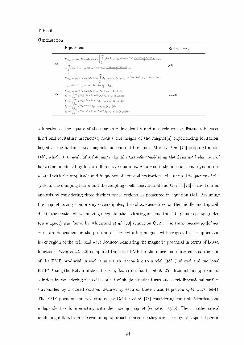
Table 6
Continuation
Equations References
Q24
Fmu = πµ0MmMurmru
[ ∞∫0
(elmk − 1)ek(ym−Su) J1(krm)J1(kru)k
dk−
−∞∫0
(elmk − 1)ek(ym−Su−lu) J1(krm)J1(kru)k
dk
] [74]
Q25
Fmu = µ0πrurmMuMm
∞∫0
J1(εru)J1(εrm)[e−ε(su+lu) + e−ε(su−lm)−
−e−ε(su) − e−ε(su+lu−lm)]ε−1dε
Fmu = µ0πrurmMuMm(I1 + I2 + I3 + I4)
I1 =∫∞
0xme−(su+lm)xJ1(rmx)J1(rux)dx
I2 =∫∞
0xme−(su+lu)xJ1(rmx)J1(rux)dx
I3 =∫∞
0xme−suxJ1(rmx)J1(rux)dx
I4 =∫∞
0xme−(su+lm+lu)xJ1(rmx)J1(rux)dx
[25,73]
a function of the square of the magnetic ux density and also relates the distances between
xed and levitating magnet(s), radius and height of the magnet(s) experiencing levitation,
height of the bottom xed magnet and mass of the stack. Morais et al. [79] proposed model
Q30, which is a result of a frequency domain analysis considering the dynamic behaviour of
harvesters modelled by linear dierential equations. As a result, the inertial mass dynamics is
related with the amplitude and frequency of external excitations, the natural frequency of the
system, the damping factor and the coupling coecient. Bernal and García [74] carried out an
analysis by considering three distinct space regions, as presented in equation Q31. Assuming
the magnet as only comprising seven dipoles, the voltage generated on the middle and top coil,
due to the motion of two moving magnets (the levitating one and the FR4 planar spring-guided
top magnet) was found by Aldawood et al. [80] (equation Q32). The three piecewise-dened
cases are dependent on the position of the levitating magnet with respect to the upper and
lower region of the coil, and were deduced admitting the magnetic potential in terms of Bessel
functions. Yang et al. [82] computed the total EMF for the inner and outer coils as the sum
of the EMF produced in each single turn, according to model Q33 (induced and motional
EMF). Using the Kelvin-Stokes theorem, Soares dos Santos et al. [25] obtained an approximate
solution by considering the coil as a set of single circular turns and a tri-dimensional surface
surrounded by a closed contour dened by each of these turns (equation Q34; Figs. 6d-f).
The EMF phenomenon was studied by Geisler et al. [73] considering multiple identical and
independent coils interacting with the moving magnet (equation Q35). Their mathematical
modelling diers from the remaining approaches because they use the magnetic spatial period
24

(distance between the centres of two consecutive coils), the parity phase (distinct value for an
even or odd number of alternate stack magnets) and the average ux over the coil thickness.
Table 7
Equations of induced electromotive force
Equations References
Q26 U = −N dφdt [6,7,13,57,64,69,71,72,76,77,85,89]
Q27 U = αy[61,66,70,78,81,83,84,87,88]
Q28 U = | dφdy|m(2πf)2Aa
c [75]
Q29 U =−NB2lrm
2lmπµ0
√3Aa(η(sd)−η(sd+ld)−η(su)−η(su+ld))
4mξ(i)
[81]
Q30 U =αAa(2πf)3√
(k/m−(2πf)2)2+(2ξ√k/m(2πf))2
[79]
Q31U =
−ιNlcy
∞∫0
(elmk − 1) ek(ym+lc/2)−ek(ym−lc/2)
k
J1(rmk)J1(rmck)dk if y ≥ ym + lm
−ιNlcy
∞∫0
e−k(ym+lm)(eklc/2−e−klc/2)+ek(ym−lc/2)−e(ym+lc/2)
k
J1(rmk)J1(rmck)dk if ym < y < ym + lm
−ιNlcy
∞∫0
(e−lmk − 1)e−kym (−e−klc/2)+eklc/2))
k
J1(rmk)J1(rmck)dk if y ≤ ym
ι = πµ0NlcMmrmrmc
[74]
Q32
U =2Nrcµ0lc
m1y
7
7∑i=1
1[
lc−2
(Sd+lm/2+ld/2−
ydt+ydb2
− (i−4)lm8
)]2+4rc2
3/2
− 1[lc+2
(Sd+lm/2+ld/2−
ydt+ydb2
− (i−4)lm8
)]2+4rc2
3/2
+m2yt
1[
lc−2
(lh−lu/2−ld/2−
ydt+ydb2
)]2+4rc2
3/2
− 1[lc+2
(lh−lu/2−ld/2−
ydt+ydb2
)]2+4rc2
3/2
Utopcoil =
2Ntrctµ0lct
m1y
7
7∑i=1
1[
lct−2
(Sd+lm/2+ld/2−
yut+yub2
− (i−4)lm8
)]2+4rct
23/2
− 1[lct+2
(Sd+lm/2+ld/2−
yut+yub2
− (i−4)lm8
)]2+4rct
23/2
+m2yt
1[
lct−2
(lh−lu/2−ld/2−
yut+yub2
)]2+4rct
23/2
− 1[lct+2
(lh−lu/2−ld/2−
yut+yub2
)]2+4rct
23/2
[80]
Q33 U =
N∑i=1
y
(−∂Byi∂h
πc2
4+ Bri l
)[82]
Q34 U = 2π ∂∂t
( Ny∑k=1
Nr∑j=1
rj∫0
B(r, yk)rdr
)[25]
Q35
U = −2Nlcφrmc cos
(2πpy + αp
)× sin
(πlcp
)y
φrmc = 1rmc
2rmc−rc∫rc
Φmax(r)dr [73]
(i) η dened in Table 6 (equation Q17).
25

4.6 Modelling the electric current in the coil
The electric current owing through the electric circuit is usually deduced using the Ohm's
law, as presented in equations Q36 to Q38 (Table 8). Some modelling approaches (Q36 and
Q39) disregarded the eects of the coil inductance on the current dynamics. By means of the
multiple scales perturbation technique and after introducing a polar form, Mann and Sims [66]
were the only authors who provided an analytical solution taken into account the non-linear
system dynamics under harmonic excitation. The current that ows through the resistive load
was modelled as a relation of proportionality between a sinusoidal function and a variable
named 'a' by the authors (equation Q39), which is a parameter that results from an analytical
solution.
Table 8
Equations of coil induced current
Equations References
Q36 I = URi+Rl
[7,69,72,76,77,83,87]
Q37 dIdt = U−I(Ri+Rl)
L [6,25,61,70,74,84,88]
Q38 dIdt = U−RiI−ui
L(i) [78]
Q39 I(t) = −(
αRl+Ri
)2πfa sin(2πft− γ)(ii) [66]
(i) There is a conditioning circuit between Ri and Rl.(ii) More information about the parameter "a" can be found in the study of Mann and Sims [66].
4.7 Modelling the electromechanical coupling coecient
The electromechanical coupling coecient relates mechanical and electrical input and output
energies. It was mainly studied using the analytical approach, as highlighted in Table 9.
This parameter was usually considered as a constant (equations Q40 to Q41), as a result
of an analysis signicantly simplied which considers a constant magnetic eld throughout
26

the tri-dimensional space enclosed by the harvester. Equations Q40 and Q41 consider the
magnetic eld and the total coil length. Models Q41 and Q42 introduce the number of
coil turns, while Dallago et al. [76] use the mean length of the coil turns (equation Q42).
Nevertheless, Kecik et al. [61] proposed a method to experimentally determinate this coecient
as a function of the non-linear position of the levitating magnet. The model is described as an
odd polynomial function of thirteen degree (equation Q43) and is parameterized by the least
squares curve-tting technique. This coecient was also considered as non-linear by several
other authors who obtained it as the sum of the electromagnetic coupling coecient of each
coil turn (equation Q44). This formulation merges with the vector magnetic potential at the
coordinates of the coil turn due to all the magnets in the system [69,70,72,84]. Some researchers
did not directly model this coecient and preferred to approach the mechanical-electrical
interaction with the Lorentz force [25,74].
Table 9
Electromechanical coupling coecient
Equations References
Q40 α = Bl [71,79,83]
Q41 α = NBl [6,57,66,81,87]
Q42 α = NB2πrmc [76]
Q43 α = a1y + a3y3 + a5y
5 + a7y7 + a9y
9 + a11y11 + a13y
13 [61]
Q44α =
Nr∑i=1
Ny∑j=1
ke_ij
ke_ij = −2πrijdAijdz , with A dened in Table 6 (Q20)
[69,70,72,84]
Q45 α =(−dλ1
dy + dλ2dy
)(i) [78]
(i) λ1 and λ2 were not dened.
27

4.8 Modelling the damping coecients and forces
Damping forces have signicant impact on the overall dynamics (amplitude and frequency)
of the motion-driven levitating magnet(s). Table 10 presents the most relevant analytical and
semi-analytical models developed so far. The mechanical damping was usually modelled as a
function of the mechanical friction due to the physical contact between the moving magnet
and the container [25], but other damping sources were also employed, such as air damping
[6]. To avoid air compression, the harvesters were commonly designed with tiny holes on the
extremities so that the air ux can leave the inner container when the stack moves in it. Model
Q46, proposed by Pancharoen et al. [81] to determine the damping factor, was experimentally
taken by stopping the shaker abruptly in order to record the attenuated response of the
harvester. They related the variation of the peak responses over time due to impulse excitations.
The damping coecient in equation Q47 is dependent on the damping factor, the mass of the
levitating stack and the natural frequency of the system [71,79]. Saravia et al. [6] modelled
the damping coecient introducing the eects of mechanical friction, air damping and electric
damping as presented in equation Q48. Dierently, the electric damping force is generated
only if a current ows through the coil, creating a magnetic eld that opposes to motion
of the levitating magnet(s). When the coil inductance is neglected, the electrical damping
coecient is mainly described by equation Q49 [7,57,66,69], which relates the square of the
electromechanical coupling coecient with the total resistance of the electric circuit. Similarly
to equation Q49, but considering the coil inductance, equation Q50 introduces the approach
taken by Constantinou et al. [70] and Foisal et al. [86]. A more complex model was implemented
by Geisler et al. [73]. In fact, these authors developed a location-dependent approach in which
some coils are equally aected by the induction, depending on the position of the inertial
levitating magnet(s). This approach was considered because an eective number of independent
multi-turn coils was included, which correspond to the coils close to the moving magnets for
the periodic model (equation Q51). As the mechanical damping factor is harvester-dependent,
Dallago et al. [76] estimated its value using a relation between the natural frequency of the
harvester and a quality factor, indirectly including the non-linearities of the system as described
by equation Q52. It is noteworthy to emphasize that, although the electric damping was usually
modelled as a function of the coupling coecient, Soares dos Santos et al. [25] and Bernal and
28
García [74] proposed to analyse this phenomenon using the Lorentz force (equations Q53 and
Q54). The model proposed by Berdy et al. [69,72] is simplied because it only provides the
eects due to the Coulomb force (equation Q55). Soares dos Santos et al. [25] modelled the
frictional force using the Karnopp friction model that considers, for both negative and positive
velocities, the eect of dierent viscous friction coecients, dierent break-away forces and
dierent Coulomb forces (equation Q56). They also considered a low velocity region where no
relative displacement occurs (Fig. 6c). The force due to the dry friction proposed by Bonisoli
et al. [78] is simpler than the Karnopp friction model developed by Soares dos Santos et al.
[25], as they only considered the Coulomb force and a break-away region (equation Q57).
Finally, a generally observed trend was the computation of the electric damping disregarding
the inuence of the mechanical damping. Moreover, the validation of models concerning the
damping factor was usually performed in an empirical basis.
5 Experimental energy outcomes
Experimental results concerning each harvester design, namely electric parameters (electric
power, voltage, current and load) and the excitation patterns are summarized in Table 11
and Fig. 8. Low excitation magnitudes drive a linear behaviour of the motion experienced
by the levitating magnet, resulting in a response with a single periodic attractor (unique
solution associated with any initial condition) as depicted in Fig. 7a. However, increasing
the external acceleration magnitudes will cause a high nonlinear behaviour characterized by
multiple periodic attractors and hysteresis (Fig. 7b) [66,90,91]. Hence, if the excitation is
enough to exhibit dierent solutions for the same initial condition, the analysis was carried
out registering the range up to the highest achievable experimental data of electric quantities
in any trajectory (ascending and descending), as illustrated in Fig. 7b [7,66]. The analysis
of simulation results was carried out by selecting the reported minimum and maximum peak
values [61,88].
The experimental validation of transduction mechanisms was performed by means of two
approaches: either by attaching the harvesters to a shaker (with previously known sinusoidal
accelerations) or by coupling them to vibrational energy sources, which usually excite the
29

Table 10
Damping coecients and forces
Equations References
Q46ξ = ψ√
4π2+ψ2
ψ = 1n ln y1
yn+1
[81]
Q47 c = 2ξmωn[64,71,75,79]
[81,83]
Q48 c = cair +cfry + U2
Rl+Ri[6]
Q49 ce = α2
Rl+Ri
[7,57,66,69,72]
[79,83,87]
Q50 ce = α2√(Rl+Ri)2+(ωL)2
[70,71]
Q51 ce(y) = NiRl+Ri
(2Nlc φrmc sin
(πlcp
))2cos2
(2πp y + αp
)[73]
Q52 cm = ωnQ [76]
Q53 Flz = 2πINy∑k=1
Nr∑j=1
Br(rj , yk)rj [25]
Q54
Flz = 2πMmrmAφ(ym + lm, rm, lc, rmc)−Aφ(ym, rm, lc, rmc)
Aφ(y, r, lc, Rmc) = µ0
2πlN Irmc
∫ π0 log
(f+(φ′,r,y;rmc,lc)f−(φ′,r,y;rmc,lc)
)dφ′
f±(φ′, r, y; rmc, lc) = 2y ± lc +√lc
2 ± 4lcy + 4(rmc2 + y2 + r2)− 8rmcr cosφ′
[74]
Q55 Ffr = sign(y)Fd [69,72]
Q56 Ffr =
fre if − fbwn < fre < fbwp
fcop + kvpdydt if dydt > vmin
−fcon + kvndydt if dydt < −vmin
[25]
Q57 Ffr =
−f(y)sign(y) if z = ±zlim, x = ±xlim
0 if |z| < zlim, |x| < xlim
[78]
harvesters with irregular accelerations. Most authors used excitations with dened amplitudes
and frequencies varying from 0.039 g to 8 g (0.38 to 78.5 m/s2) and from 0.75 to 46 Hz,
30

respectively. Interestingly, accelerations and dominant frequencies lower than 1 g and 15 Hz,
respectively, were driven in most of the studies that used sinusoidal excitations (Fig. 8). Several
customized excitations were applied to the harvesters, namely by tyre moving (harvesters
housed radially into the inner layer of a tyre as shown in Fig. 3f) [78], hand shaking (Fig. 1d)
[73,87] and other human body motions at various speeds (harvesters attached to upper arm,
hip, lower-limb, chest's side, back, among other locations as illustrated in Figs. 1e, 2i,j and
4f,g) [7,64,72,73,75].
More than two thirds of the studies were conducted using resistive loads similar to the coil
resistance of the harvester, ensuring maximum electric power transfer. The load resistance
applied by the authors was between 4 Ω and 1 MΩ. The electric power outcome is of
paramount importance when evaluating the harvester eciency. Instantaneous power levels
up to 1.9 W were achieved, although most of the studies did not exceed 6 mW. These are
not impressive magnitudes, mainly if we consider the ability of these harvesters for large-scale
electric powering. Nevertheless, they are related to small-scale harvesters that were prototyped
so far (volumes up to 235 cm3, as highlighted in Table 1). Although most studies report power
densities in the 20 - 70 µW/cm3 range, densities up to 8015 µW/cm3 (≈8 kW/m3) were already
achieved, which allow to predict their eective application in large-scale devices. Load voltages
in the 0.3 7 V range (maximum of 43.4 V) and electric currents up to 21.5 mA (maximum
of 150 mA) were measured.
Open load conditions were discarded from the analysis between categories. The harvesters
from the rst category provided electric power in the range from 15 µW to 180 mW [84,87]
and power densities in the range from 3.5 to 7229 µW/cm3 [86,87]. The maximum voltage and
current achieved were 6 V (for 3.5 kΩ of resistive load) and 150 mA (for 4 Ω load), respectively
[25,70]. When considering the developed harvesters from the second category, electric power
was monitored between 15 µW to 1.9 W [57,64] with power densities from 1.1 to 8015 µW/cm3
[7,57]. The maximum voltage and current achieved were 43.4 V and 43.4 mA (under 1 kΩ load),
respectively [57]. In the third category, power levels from 300 µW to 69.3 mW [79,82] and power
densities from 79.8 to 1710 µW/cm3 were achieved [79]. Maximum voltage and current were
measured up to 8 V and 21.5 mA, respectively [78,82]. Finally, the maximum power and power
density associated with the fourth category ranged from 40 µW to 85 mW [6,75] and 0.3 to
31

2080 µW/cm3, respectively [75,83]. Up to 7 V was measured for the maximum load voltage
(for 3.8 kΩ load) and up to 29.2 mA for the electric current (under 100 Ω load) [6,83].
Table 11
Harvesters performance(a)
Referencesz
[m/s2]
Rl[Ω]
P
[mW]
Pρ
[µW/cm3]
U
[V]I
[mA]
Category
1
Constantinou,Mellor,
Wilcox[84]4.3g sin(2π46t) 9 180
(RMS) 4500 1.3(RMS)
140(RMS)
Constantinou,Mellor, Wilcox[70]
2g sin(2π37t) ≈4 90(AVR) 600 0.6
(AVR)150
(AVR)
Bernal, García[74] ND ND ND ND ND ND
Foisal, Hong,Chung [71]
0.5g sin(2πft)7<f<10
ND
2.37(MAX) 21.92 ND ND
2.09(MAX) 52.02 ND ND
Foisal, Lee, Chung[85]
0.16g sin(2π9t) 97 1.18(MAX) ≈159.7 0.3
(MAX)3.5
(MAX)
Foisal, Chung[86]
0.13g sin(2π8.1t) 97 53.5(MAX) ≈7229 2.3
(MAX)23.4
(MAX)
Berdy, Valentino,Peroulis [69]
0.1g sin(2π6.7t) 1×10³ 0.41(MAX) 53.2 0.6
(MAX)0.6
(MAX)
Berdy, Valentino,Peroulis [72]
0.075g sin(2π6.7t) ND 0.33(MAX) 42.9 ND ND
cust.
4.8-9.7 km/h 1×10³ 0.071-0.34(RMS) 9.2-44.4 0.3-0.6
(RMS)0.3-0.6(RMS)
Liu et al. [87]
A sin(2πft)0.45g<A<0.6g
4.4<f<4.8
10 0.015-0.28(RMS) 3.5-45.3 0.012-0.053
(RMS)1.2-5.3(RMS)
cust.f=4.5;A=0.01m 6 < 93 ≈0.1-0.31
(RMS) ≈15.9-49.4 ≈0.035-0.094(RMS)
≈1-5.6(RMS)
cust.f=6.7;A=0.01/0.02m 10
0.57/0.65(RMS)
90.7/104≈0.075/0.081
(RMS)7.5/8.1(RMS)
Santos et al. [25]
A sin(2πft)0.84g<A<1.96g
3.5<f<9
3.5×10³ ≈0.8-10.3(MAX)
≈66.7-858.3
≈1.7-6(MAX)
≈0.5-1.7(MAX)
A sin(2πft)0.84g<A<1.8g
3.5<f<8
8.9×10⁴ ≈0.1-1.1(MAX)
≈11.7-93.3
≈3.5-10(MAX)
≈0.039-0.1(MAX)
Kecik et al. [61]A sin(2πft)A<10.2g
f<15.9
ND ND ND ND ≈0-38(MAX)
K¦cik [88]A sin(2πft)
0.05g<A<14.3g
1.6<f<15.9
1.1×10³ ND ND ND ≈0-56(MAX)
Category
2
Saha et al. [64]0.039g sin(2π7.6t) 7300 0.015
(MAX) 1.18 0.3(MAX)
0.045(MAX)
cust.2<f<2.75;0.5g<A<1g 800 0.3-2.46
(AVR)74.8-193.7
0.9-1.4(AVR)
1-1.8(AVR)
Dallago, Marchesi,Venchi [76]
1g sin(2πft)f=9/10.4
10-1×10⁴ ≈0.48-24 ≈36.9-
1846≈0.25-
3.2 ≈0.2-25
Munaz, Lee,Chung [13]
0.5g cos(2π6t) 1×10³ 4.84(RMS) 535 2.2
(RMS)2.2
(RMS)
Masoumi, Wang[57]
3.4g sin(2πft)6<f<12
1×10³ 190-1.8×10³
(MAX)≈808.5-7831
13.8-42.9(MAX)
13.8-42.9(MAX)
A sin(2π9t)1.22g<A<3.41g
1×10³ 3.8-1.9×10³
(MAX)≈16.2-8015
1.9-43.4(MAX)
1.9-43.4(MAX)
Wang et al. [7]
A sin(2πft)0.35g<A<0.85g
4<f<10
1×10⁴ 0-0.081(MAX) ≈0-1.1 0-0.9
(MAX)0-0.09(MAX)
cust.
5-9 km/h 5 0.4-6(AVR) ≈5.6-60 0.2-0.7
(MAX)8.9-34.6(AVR)
Pancharoen, Zhu,Beeby [81]
0.5g sin(2π14t) 247 8.1×10⁻³ ≈16.2 0.04 0.2
Struwig,Wolhuter, Niesler
[77]
cust.A=2.2g 40 1.7-1.9
(AVR)106.4-122.8
0.26-0.27(AVR)
6.5-6.8(AVR)
32

Table 11
Continuation
Referencesz
[m/s2]
Rl[Ω]
P
[mW]
Pρ
[µW/cm3]
U
[V]I
[mA]
Category
3
Mann, Sims [66]A sin(2πft)
0.21g<A<0.95g
6<f<13
1×10⁶ ≈1.6×10⁻⁴-0.13 (MAX)
ND ≈0.4-11.6(MAX)
≈4×10⁻⁴-1.2×10⁻²
(MAX)
Bonisoli et al. [78]cust.
40-100 km/h ND 2-11(AVR) ND 2-8
(MAX) ND
Morais et al. [79]A sin(2πft)
0.09g<A<0.55g
0.75<f<1.85
5×10³ ≈0.3-6.5(RMS)
≈79.81710
≈1.2-5.6(RMS)
≈0.2-1.1(RMS)
Morgado et
al.[89]cust.(b) - - - - -
Yang et al. [82] 8g sin(2π20t) ND 28.3(MAX) ND 2.67
(MAX)10.59(MAX)
Aldawood,Nguyen,
Bardaweel [80]0.04g sin(2π11t) 150 ≈69.3 ≈315.2 ≈3.2 ≈21.5
Category
4
Saravia, Ramírez,Gatti [6]
1g sin(2πft)4<f<10
100 ≈5-85(MAX)
≈67.6-1148
≈0.8-2.9(MAX)
≈7.1-29.2(MAX)
Geisler et al. [73]
1g sin(2π9.5t) 950 ≈2.25(MAX) ≈250 ≈1.5
(MAX)≈1.5(MAX)
cust.
6.4/8 km/h 950 3.9-5(AVR) 438-550 1.9-2.2
(AVR)2-2.3(AVR)
cust.f=6;A=2g 950 6.6
(AVR) 730 2.5(AVR)
2.6(AVR)
Apo, Priya [83]A sin(2πft)0.25g<A<1g
13<f<16
3.8×10³ 5.9-12.9(RMS)
958-2080
4.7-7(RMS)
1.2-1.8(RMS)
Zhang, Wang,Kim [75]
A sin(2π4t)0.03g<A<0.11g
96 0.04-1.23(RMS) 0.3-10.3 0.1-0.7
(RMS)0.6-3.5(RMS)
cust.
1.6-12.9 km/h 96 ≈0-32 ≈0-266.7 ≈0-1.8 ≈0-18.3
Struwig,Wolhuter, Niesler
[77]
cust.A=2.2g 40 3
(AVR) 179.4 0.35(AVR)
8.7(AVR)
(a) Terminology: ND - not dened; cust. - customized; AVR - average; MAX - maximum; RMS - root mean square.(b) OC free fall test from a height of 15mm.
6 Design optimizations
Some research eorts have been conducted so far to develop optimized motion-driven
electromagnetic energy harvesters using magnetic levitation architectures. The addressed
optimization methodology followed by each author is presented in Table 12. The appropriate
selection of materials (with low friction coecient and negligible magnetic permeability),
as well as good surface nish (to minimize its roughness and non-linearities due to
contact friction), are required to manufacture the container. Nevertheless, the harvester
characteristics must be optimized prior to fabrication to ensure maximum eciency for known
and narrowband excitations, even though their application may impose hard dimensional
constraints, unconstrained motion amplitudes and arbitrary orientations [25]. The design
optimizations were carried out by analysing the eects by varying: (i) the distance between
the xed magnets [6,7,71,77,84]; (ii) the dimensions, mass and number of inertial magnet(s)
33

[6,13,57,69,73,77,79,83,85,86,88]; and (iii) the coil(s) properties (number of turns, width, height,
position) [69,71,73,77,79,81,83,8587]. The proper selection of the shaft material [70], container
material [72] and spacer material (with dierent permeabilities) [57] was also analysed in
some studies. An innovative optimization method was proposed by Diala et al. [92] using
the Associated Linear Equations (ALEs) of the nonlinear system to obtain the Output
Frequency Response Function. Noticeably, no models developed and validated so far (for two
or tri-dimensional motions of the harvesters) were used to optimize (prior fabrication) the
container, coil(s) and magnets. Consequently, the inuence of the design parameters is currently
unknown for multivariable performance optimization. This nding is noticeable when analysing
Fig. 8, as no correlation between the external excitation and the power density was found.
Moreover, as no adaptive mechanisms were already proposed to maximize the energy eciency
for time-varying patterns of external mechanical power sources, it is currently unknown how
much the power density can be maximized.
Table 12
Optimization methodologies(a)
References Description
Category
1
Constantinou,Mellor,
Wilcox[84](3) Distance between xed magnets.
Constantinou,Mellor, Wilcox[70]
(3) Shaft material and (3) shaft cross sections (bearing contact area).
Bernal, García[74] NO
Foisal, Hong,Chung [71]
Number of coil turns, coil width, coil position and distance between xed magnets.
Foisal, Lee, Chung[85]
Permanent magnets dimensions, coil width and coil position.
Foisal, Chung[86]
Inertial mass, size of xed magnets, coil width and coil position.
Berdy, Valentino,Peroulis [69]
Section for the container (rectangular, due to volume restrictions), dimensions ofpermanent magnets, number of coil turns and coil position.
Berdy, Valentino,Peroulis [72]
Container cross section (with and without a guide rail) and container material.
Liu et al. [87] (3) Distance between xed magnets and coil width.
Santos et al. [25] NO
Kecik et al. [61] NO
K¦cik [88] Repulsive magnetic force, coil inductance and coupling coecient inuence.
34

Table 12
Continuation
References Description
Category
2
Saha et al. [64] NO
Dallago, Marchesi,Venchi [76]
NO
Munaz, Lee,Chung [13]
Length of xed magnets and number of levitating magnets.
Masoumi, Wang[57]
Magnet stack assembly conguration, spacers thickness and material (with dierentpermeabilities).
Wang et al. [7]Magnet stack assembling conguration, (3/6) number of levitating magnets and (2)spacing between xed magnets.
Pancharoen, Zhu,Beeby [81]
Coil resistance.
Struwig,Wolhuter, Niesler
[77]
Number of coils, coil height, coil spacing, number of magnets, distance between levitatingmagnets and overall size of the device.
Category
3
Mann, Sims [66] NO
Bonisoli et al. [78] NO
Morais et al. [79] Coil length, weight and height of the inertial mass.
Morgado et
al.[89]NO
Yang et al. [82] NO
Aldawood,Nguyen,
Bardaweel [80]NO
Category
4
Saravia, RamírezGatti [6]
Number of levitating magnets, inuence of spacers and spacing between xed magnets.
Geisler et al. [73]
Permanent magnets dimensions, total inertial mass, inertial mass displacement, magneticperiod, number of turns per coil, coil resistance, coil outer diameter, average magneticux and average electric damping.
Apo, Priya [83] Dimensions and number of levitating magnets and coil height.
Zhang, Wang,Kim [75]
NO
(a) Terminology: NO - not optimized.
7 Discussion and conclusions
In this paper we present a systematic review of relevant literature reports that highlight
major scientic achievements in the design of electromagnetic energy harvesters with
mono-stable magnetic levitation architectures. It focuses their major features concerning design
congurations, construction parameters, modelling and experimental validation of transduction
mechanisms and energy outcomes. Recent research ndings show the potential of these
electromagnetic harvesters to electrically power a wide range of devices requiring self-powering,
from small-scale to large-scale electric systems. The reduced intermittence exhibited by these
energy harvesting systems is a signicant advantage over many other electric power generators.
35

Besides, maintenance requirements are remarkably reduced in comparison to current large-scale
energy systems because: (i) the number of components is lower, as no coupling, motion
transmission or motion transformation systems are required; (ii) their components do not
undergo critical wear, as the current performances of permanent magnets ensure a very
long service time. For example, neodymium magnets only lose a very small fraction of their
magnetic strength over the years under optimum working conditions, which are fullled in many
large-scale applications if the harvesters are hermetically encapsulated; (iii) the non-levitating
magnets do not allow that levitating magnet(s) can be damaged throughout energy harvesting;
(iv) the transduction mechanism design is not complex, as the mechanical design does not
demand turbines or oleo-hydraulic systems, among other complex systems, and the electrical
design is usually based on coil(s) wrapping the outer surface of containers; (v) the mechanical
friction of moving components is much lower since only the levitating magnet(s) experience(s)
the friction on the magnet(s)-container interface. As a result, reduced maintenance and
production costs are expected. These technologies are scalable and adaptable, enabling the
implementation of harvesters with dierent sizes and for dierent external excitations. Hence,
they can be optimized and customized for large-scale power generation, like the conversion of
ocean energy into electric energy by generators using magnetic levitation [57,58,65]. Due to
their non-intermittent operation, these generators hold potential to provide higher eciency
when compared with electric powering using the wind or sun as the primary power source.
Besides, the simplicity of their mechanical and electrical designs ensures long-term operation
with reduced performance losses. Nevertheless, the optimization of these harvesters is an
important task leading to viable alternatives relatively to batteries and other conventional
non-renewable energy sources.
In conclusion, the following core ndings can be highlighted:
(1) Twenty-nine relevant studies focused on electromagnetic energy harvesting with
mono-stable magnetic levitation architectures were found;
(2) Twenty-one design congurations were already studied and demonstrate promising results
for future applications of energy harvesting both for small-scale and large-scale electric
powering;
36

(3) Four categories of energy harvesters emerged according to the number of coils and
levitating magnets. Architectures including levitating magnets coupled to springs and
magnets moving according to guidance systems were also considered, as well as those
using top magnets coupled to planar springs;
(4) Relevant approaches to model each physical phenomenon were explored. Most authors
focused on modelling the magnetic eld from levitating magnets, repulsive magnetic
forces between permanent magnets, induced voltage in the coil terminals, electric current,
electromechanical coupling coecient and damping forces;
(5) Four modelling approaches were distinguished to model each physical phenomenon:
empirical, analytical, semi-analytical, and nite element method. Almost all authors
conducted a hybridization on their models, which resulted in the development of
analytical-empirical-FEM, analytical-empirical and analytical-semi-analytical-empirical
models;
(6) Experimental validations of many transduction mechanisms were successfully achieved;
(7) Experimental energy outcomes leave no doubt about the potential of these harvesters
to supply energy to multifunctional micro-systems and to provide large-scale electric
powering. Densities up to 8 mW/cm3 (8 kW/m3) have already been achieved;
(8) Voltages and currents up to 43.4 V and 150 mA were measured for volumes up to 235
cm3;
(9) No multivariable performance optimization has already been performed. Consequently,
the inuence of the design parameters are currently unknown in multivariable approaches;
(10) Although prototypes have been developed for small-scale testing, electromagnetic energy
generators using magnetic levitation can be scaled up and customized for large-scale
power generation with reduced maintenance and production costs expected.
37

8 Future research prospects
The main limitation of electromagnetic energy harvesters is their highly non-linear behaviour,
which makes performance maximization hard to achieve. The accurate modelling of their
energy transduction mechanisms is mandatory. It is noteworthy to state that, even though
current ndings seem to highlight a strong societal impact of these harvesters in the near
future, their designs ensuring competitive energy production costs still demand intensive
research eorts to optimize harvesting performance. For future applications in both small-scale
and large-scale power generation, a multivariable geometric optimization prior to fabrication
must be conducted. Besides, design optimization must be performed using very accurate
computational models to predict both the mechanical and electric dynamics for tri-dimensional
motions of the harvester due to realistic excitation patterns of external mechanical power
sources. New methodologies must be implemented to optimize harvester architectures so that
their performance can be maximized for unknown and time-varying patterns of mechanical
power sources exciting the harvesters. Large-scale prototypes must be developed to trigger
detailed analyses to their harvesting performances, as well as to identify the main problems
that emerge when these technologies are scaled up. Finally, realistic economic studies must
be conducted to estimate their maintenance and production costs in order to evaluate their
competitiveness in the energy market.
Acknowledgement
This work was funded by Portuguese Foundation for Science and Technology
(grant references SFRH/BPD/117475/2016 and BI/UI66/8372/2018, project reference
POCI-01-0145-FEDER-031132). It was also support by the Centre for Mechanical Technology
& Automation (UID/EMS/00481/2019-FCT and CENTRO-01-0145-FEDER-022083). This
work was developed within the scope of the project CICECO - Aveiro Institute of Materials,
FCT Ref. UID/CTM/50011/2019, nanced by national funds through the FCT/MCTES.
The project POCI-01-0247-FEDER-007678 SGH "Smart Green Homes" is acknowledged.
The research was also supported by the Ministry of Education and Science of the Russian
38

Federation in the framework of the Increase Competitiveness Program of NUST MISiS (no.
K2-2019-015).
Additional information
Competing nancial interests: The authors declare no competing nancial interests.
References
[1] Le MQ, Capsal JF, Lallart M, Hebrard Y, Van Der Ham A, Ree N, et al. Review on
energy harvesting for structural health monitoring in aeronautical applications. Progress
in Aerospace Sciences. 2015;79:147157. doi:10.1016/j.paerosci.2015.10.001.
[2] Abdelke A. Aeroelastic energy harvesting: A review. International Journal of Engineering
Science. 2016;100:112135. doi:10.1016/j.ijengsci.2015.10.006.
[3] Harb A. Energy harvesting: state-of-the-art. Renewable Energy. 2011;36(10):26412654.
doi:10.1016/j.renene.2010.06.014.
[4] Bowen CR, Kim HA, Weaver PM, Dunn S. Piezoelectric and ferroelectric materials
and structures for energy harvesting applications. Energy and Environmental Science.
2014;7(1):2544. doi:10.1039/c3ee42454e.
[5] Siddique ARM, Mahamud S, Heyst BV. A comprehensive review on vibration based micro
power generators using electromagnetic and piezoelectric transducer mechanisms. Energy
Conversion and Management. 2015;106:728747. doi:10.1016/j.enconman.2015.09.071.
[6] Saravia CM, Ramírez JM, Gatti CD. A hybrid numerical-analytical approach for
modeling levitation based vibration energy harvesters. Sensors & Actuators: A Physical.
2017;257:2029. doi:10.1016/j.sna.2017.01.023.
[7] Wang W, Cao J, Zhang N, Lin J, Liao WH. Magnetic-spring based energy harvesting from
human motions: Design, modeling and experiments. Energy Conversion and Management.
2017;132:189197. doi:10.1016/j.enconman.2016.11.026.
39

[8] Mitcheson PD, Yeatman EM, Rao GK, Holmes AS, Green TC. Energy harvesting from
human and machine motion for wireless electronic devices. Proceedings of the IEEE.
2008;96(9):14571486. doi:10.1109/JPROC.2008.927494.
[9] Want R, Farkas KI, Narayanaswami C. Guest editors' introduction: Energy harvesting
and conservation. IEEE Distributed Systems Online. 2005;6(3):1417.
[10] Clark WW. Special issue on energy harvesting. Journal of Intelligent Material Systems
and Structures. 2005;16(10):783. doi:10.1177/1045389X05056683.
[11] Elliott D. A balancing act for renewables. Nature Energy. 2016;1(1):15003.
doi:10.1038/nenergy.2015.3.
[12] Larsson S, Fantazzini D, Davidsson S, Kullander S, Höök M. Reviewing
electricity production cost assessments. Renewable and Sustainable Energy Reviews.
2014;30:170183. doi:10.1016/j.rser.2013.09.028.
[13] Munaz A, Lee BC, Chung GS. A study of an electromagnetic energy harvester
using multi-pole magnet. Sensors & Actuators A: Physical. 2013;201:134140.
doi:10.1016/j.sna.2013.07.003.
[14] Albadi M, El-Saadany E. Overview of wind power intermittency impacts on power systems.
Electric Power Systems Research. 2010;80(6):627632. doi:10.1016/j.epsr.2009.10.035.
[15] Sovacool BK. The intermittency of wind, solar, and renewable electricity generators:
technical barrier or rhetorical excuse? Utilities Policy. 2009;17(3-4):288296.
doi:10.1016/j.jup.2008.07.001.
[16] Falcão AFdO. Wave energy utilization: a review of the technologies. Renewable and
Sustainable Energy Reviews. 2010;14:899918. doi:10.1016/j.rser.2009.11.003.
[17] López I, Andreu J, Ceballos S, Alegría IMD, Kortabarria I. Review of wave energy
technologies and the necessary power-equipment. Renewable and Sustainable Energy
Reviews. 2013;27:413434. doi:10.1016/j.rser.2013.07.009.
[18] European Comission. Energy roadmap 2050. European Union. 2012;p. 20.
doi:10.2833/10759.
40

[19] Conti J, Holtberg P, Diefenderfer J, LaRose A, Turnure JT, Westfall L. International
Energy Outlook 2016 With Projections to 2040. U.S. Energy Information Administration;
2016.
[20] Beeby SP, Tudor MJ, White NM. Energy harvesting vibration sources for
microsystems applications. Measurement Science and Technology. 2006;17(12):175195.
doi:10.1088/0957-0233/17/12/R01.
[21] Dewan A, Ay SU, Karim MN, Beyenal H. Alternative power sources for
remote sensors: A review. Journal of Power Sources. 2014;245(1):129143.
doi:10.1016/j.jpowsour.2013.06.081.
[22] Khaligh A, Member S, Zeng P, Member S, Zheng C, Member S. Kinetic energy harvesting
using pizoelectric and electromagnetic technologies - state of the art. IEEE Transactions
on Industrial Electronics. 2010;57(3):850860. doi:10.1109/TIE.2009.2024652.
[23] Teng XF, Zhang YT, Poon CCY, Bonato P. Wearable medical systems for p-health. IEEE
Reviews in Biomedical Engineering. 2008;1:6274. doi:10.1109/RBME.2008.2008248.
[24] Wu Z, Tang J, Zhang X, Yu Z. An energy harvesting bracelet. Applied Physics Letters.
2017;111(1). doi:10.1063/1.4991666.
[25] dos Santos MPS, Ferreira JAF, Simões JAO, Pascoal R, Torrão J, Xue X, et al. Magnetic
levitation-based electromagnetic energy harvesting: a semi-analytical non-linear model for
energy transduction. Scientic Reports. 2016;6(18579):19. doi:10.1038/srep18579.
[26] Gie RP, Beyers N. Energy scavenging for mobile and wireless electronics. IEEE Pervasive
Computing. 2005;4(1):1827. doi:10.1109/MPRV.2005.9.
[27] Koo MM, Cho IH, Hong K, Kim JM, Choi JY, Jeong JH. Design and analysis of tubular
permanent magnet linear generator for small-scale wave energy converter. AIP Advances.
2017;7(5):056630. doi:10.1063/1.4974496.
[28] Li WJ, Wen Z, Wong PK, Chan GMH, Leong PHW. A micromachined vibration-induced
power generator for low power sensors of robotic systems. World Autom Congr 8th Int
Symp Robot Appl. 2000;.
41

[29] Williams CB, Yates RB. Analysis of a micro-electric generator for microsystems. Sensors
and Actuators, A: Physical. 1996;52(1-3):811. doi:10.1016/0924-4247(96)80118-X.
[30] Sardini E, Serpelloni M. An ecient electromagnetic power harvesting device for
low-frequency applications. Sensors and Actuators A: Physical. 2011;172(2):475482.
doi:10.1016/j.sna.2011.09.013.
[31] Shahosseini I, Naja K. Cylindrical halbach magnet array for electromagnetic vibration
energy harvesters. 28th IEEE International Conference on Micro Electro Mechanical
Systems (MEMS). 2015;p. 10511054. doi:10.1109/MEMSYS.2015.7051143.
[32] Alemzadeh H, Iyer RK, Kalbarczyk Z, Raman J. Analysis of safety-critical
computer failures in medical devices. IEEE Security and Privacy. 2013;11(4):1426.
doi:10.1109/MSP.2013.49.
[33] Soares dos Santos MP, Ferreira JAF, Ramos A, Simões JAO, Morais R, Silva NM,
et al. Instrumented hip implants: Electric supply systems. Journal of Biomechanics.
2013;46(15):25612571. doi:10.1016/j.jbiomech.2013.08.002.
[34] Soares dos Santos MP, Coutinho J, Marote A, Sousa B, Ramos A, Ferreira JAF,
et al. Capacitive technologies for highly controlled and personalized electrical
stimulation by implantable biomedical systems. Scientic Reports. 2019;9(1).
doi:10.1038/s41598-019-41540-3.
[35] Dos Santos MPS, Marote A, Santos T, Torrão J, Ramos A, Simões JAO, et al. New
cosurface capacitive stimulators for the development of active osseointegrative implantable
devices. Scientic Reports. 2016;6(30231). doi:10.1038/srep30231.
[36] Bernardo R, Rodrigues A, dos Santos MPS, Carneiro P, Lopes A, Amaral JS, et al. Novel
magnetic stimulation methodology for
low-current implantable medical devices. Medical Engineering & Physics. 2019;73:77
84. doi:https://doi.org/10.1016/j.medengphy.2019.07.015.
[37] Prescott JH, Lipka S, Baldwin S, Jr NFS, Maloney JM, Coppeta J, et al. Chronic,
programmed polypeptide delivery from an implanted, multireservoir microchip device.
Nature Biotechnology. 2006;24(4):437438. doi:10.1038/nbt1199.
42

[38] Panuccio G, Semprini M, Chiappalone M. Intelligent biohybrid systems for
functional brain repair. New Horizons in Translational Medicine. 2016;3(3):162 174.
doi:https://doi.org/10.1016/j.nhtm.2016.10.001.
[39] dos Santos MPS, Ferreira JAF, Ramos A, Simões JAO. Active orthopaedic implants:
Towards optimality. Journal of the Franklin Institute. 2015;352(3):813 834.
doi:https://doi.org/10.1016/j.jfranklin.2014.11.005.
[40] Ferguson JE, Redish AD. Wireless communication with implanted medical devices
using the conductive properties of the body. Expert Review of Medical Devices.
2011;8(4):427433. doi:10.1586/erd.11.16.Wireless.
[41] Catrysse M, Hermans B, Puers R. An inductive power system with integrated bi-directional
data-transmission. Sensors and Actuators A: Physical. 2004;115(2-3):221229.
doi:10.1016/j.sna.2004.02.016.
[42] Haroun A, Yamada I, Warisawa S. Study of electromagnetic vibration energy harvesting
with free/impact motion for low frequency operation. Journal of Sound and Vibration.
2015;349:389402. doi:10.1016/j.jsv.2015.03.048.
[43] Roundy S. On the eectiveness of vibration-based energy harvesting. Journal of Intelligent
Material Systems and Structures. 2005;16(10):809823. doi:10.1177/1045389X05054042.
[44] Arroyo E, Badel A, Formosa F, Wu Y, Qiu J. Comparison of electromagnetic and
piezoelectric vibration energy harvesters: Model and experiments. Sensors and Actuators,
A: Physical. 2012;183:148156. doi:10.1016/j.sna.2012.04.033.
[45] Gao M, Wang Y, Wang Y, Wang P. Experimental investigation of non-linear multi-stable
electromagnetic-induction energy harvesting mechanism by magnetic levitation oscillation.
Applied Energy. 2018;220:856875. doi:10.1016/j.apenergy.2018.03.170.
[46] Nammari A, Doughty S, Savage D, Weiss L, Jaganathan A, Bardaweel H.
Design and analysis of a small-scale magnetically levitated energy harvester
utilizing oblique mechanical springs. Microsystem Technologies. 2017;23:46454657.
doi:10.1007/s00542-017-3324-x.
43

[47] Beeby SP, Torah RN, Tudor MJ, Glynne-Jones P, O'Donnell T, Saha CR, et al. A micro
electromagnetic generator for vibration energy harvesting. Journal of Micromechanics and
Microengineering. 2007;17(7):12571265. doi:10.1088/0960-1317/17/7/007.
[48] Li M, Jing X. Novel tunable broadband piezoelectric harvesters for ultralow-frequency
bridge vibration energy harvesting. Applied Energy. 2019;255:113829.
doi:https://doi.org/10.1016/j.apenergy.2019.113829.
[49] Berdy DF, Srisungsitthisunti P, Jung B, Xu X, Rhoads JF, Peroulis D. Low-frequency
meandering piezoelectric vibration energy harvester. IEEE
Transactions on Ultrasonics, Ferroelectrics, and Frequency Control. 2012;59(5):846858.
doi:10.1109/TUFFC.2012.2269.
[50] Kim HS, Kim JH, Kim J. A review of piezoelectric energy harvesting based on vibration.
International Journal of Precision Engineering and Manufacturing. 2011;12(6):11291141.
doi:10.1007/s12541-011-0151-3.
[51] Varpula A, Laakso SJ, Havia T, Kyynäräinen J, Prunnila M. Harvesting vibrational energy
using material work functions. Scientic Reports. 2014;4. doi:10.1038/srep06799.
[52] Roundy S, Wright PK, Rabaey J. A study of low level vibrations as a power
source for wireless sensor nodes. Computer Communications. 2003;26:11311144.
doi:10.1016/S0140-3664(02)00248-7.
[53] Meninger S, Mur-miranda JO, Amirtharajah R, Chandrakasan AP, Lang JH.
Vibration-to-electric energy conversion. IEEE Transactions on Very Large Scale
Integration (VLSI) Systems. 2001;9(1):6476. doi:10.1109/92.920820.
[54] Tarelho JPG, Soares dos Santos MP, Ferreira JAF, Ramos A, Kopyl S, Kim SO, et al.
Graphene-based materials and structures for energy harvesting with uids - a review.
Materials Today. 2018;21(10):10191041. doi:10.1016/j.mattod.2018.06.004.
[55] Zhang Z, He J, Wen T, Zhai C, Han J, Mu J, et al. Magnetically levitated-triboelectric
nanogenerator as a self-powered vibration monitoring sensor. Nano Energy.
2017;33(December 2016):8897. doi:10.1016/j.nanoen.2017.01.031.
44

[56] Wang ZL, Jiang T, Xu L. Toward the blue energy dream by triboelectric nanogenerator
networks. Nano Energy. 2017;39:923. doi:10.1016/j.nanoen.2017.06.035.
[57] Masoumi M, Wang Y. Repulsive magnetic levitation-based ocean wave energy harvester
with variable resonance: Modeling, simulation and experiment. Journal of Sound and
Vibration. 2016;381:192205. doi:10.1016/j.jsv.2016.06.024.
[58] Harne RL, Schoemaker ME, Dussault BE, Wang K. Wave
heave energy conversion using modular multistability. Applied Energy. 2014;130:148156.
doi:10.1016/j.apenergy.2014.05.038.
[59] Zhang Z, Zhang X, Rasim Y, Wang C, Du B, Yuan Y. Design, modelling and practical
tests on a high-voltage kinetic energy harvesting (EH) system for a renewable road
tunnel based on linear alternators. Applied Energy. 2016;164(October 2015):152161.
doi:10.1016/j.apenergy.2015.11.096.
[60] Soares Dos Santos MP, Ferreira JAF, Ramos A, Simões JAO, Morais R, Silva
NM, et al. Instrumented hip joint replacements, femoral replacements and
femoral fracture stabilizers. Expert Review of Medical Devices. 2014;11(6):617635.
doi:10.1586/17434440.2014.946695.
[61] Kecik K, Mitura A, Lenci S, Warminski J. Energy harvesting from a magnetic
levitation system. International Journal of Non-Linear Mechanics. 2017;94:200206.
doi:10.1016/j.ijnonlinmec.2017.03.021.
[62] Mitcheson PD, Green TC, Yeatman EM, Holmes AS. Architectures for vibration-driven
micropower generators. Journal of Microelectromechanical Systems. 2004;13(3):429440.
doi:10.1109/JMEMS.2004.830151.
[63] Zhu D, Tudor MJ, Beeby SP. Strategies for increasing the operating frequency
range of vibration energy harvesters: A review. Measurement Science and Technology.
2010;21(022001):29. doi:10.1088/0957-0233/21/2/022001.
[64] Saha CR, O'Donnell T, Wang N, Mccloskey P. Electromagnetic generator for harvesting
energy from human motion. Sensors and Actuators A: Physical. 2008;147:248253.
doi:10.1016/j.sna.2008.03.008.
45

[65] Wei C, Jing X. A comprehensive review on vibration energy harvesting:
Modelling and realization. Renewable and Sustainable Energy Reviews. 2017;74:118.
doi:10.1016/j.rser.2017.01.073.
[66] Mann BP, Sims ND. Energy harvesting from the nonlinear oscillations of
magnetic levitation. Journal of Sound and Vibration. 2009;319(1-2):515530.
doi:10.1016/j.jsv.2008.06.011.
[67] Yildirim T, Ghayesh MH, Li W, Alici G. A review on performance enhancement techniques
for ambient vibration energy harvesters. Renewable and Sustainable Energy Reviews.
2017;71:435449. doi:10.1016/j.rser.2016.12.073.
[68] Zhang Y, Cai CS, Kong B. A low frequency nonlinear energy harvester with large
bandwidth utilizing magnet levitation. Smart Materials and Structures. 2015;24(4):045019.
doi:10.1088/0964-1726/24/4/045019.
[69] Berdy DF, Valentino DJ, Peroulis D. Design and optimization of a magnetically
sprung block magnet vibration energy harvester. Sensors and Actuators, A: Physical.
2014;218:6979. doi:10.1016/j.sna.2014.06.011.
[70] Constantinou P, Mellor PH, Wilcox PD. A magnetically sprung generator for energy
harvesting applications. IEEE/ASME Transactions on Mechatronics. 2012;17(3):415424.
doi:10.1109/TMECH.2012.2188834.
[71] Foisal ARM, Hong C, Chung GS. Multi-frequency electromagnetic energy harvester
using a magnetic spring cantilever. Sensors & Actuators: A Physical. 2012;182:106113.
doi:10.1016/j.sna.2012.05.009.
[72] Berdy DF, Valentino DJ, Peroulis D. Kinetic energy harvesting from human walking and
running using a magnetic levitation energy harvester. Sensors and Actuators, A: Physical.
2015;222:262271. doi:10.1016/j.sna.2014.12.006.
[73] Geisler M, Boisseau S, Perez M, Gasnier P, Willemin J, Ait-Ali I, et al. Human-motion
energy harvester for autonomous body area sensors. Smart Materials and Structures.
2017;26(3):12. doi:10.1088/1361-665X/aa548a.
46
[74] Bernal AA, García L. The modelling of an electromagnetic energy harvesting architecture.
Applied Mathematical Modelling. 2012;36:47284741. doi:10.1016/j.apm.2011.12.007.
[75] Zhang Q, Wang Y, Kim ES, Zhang Q, Wang Y, Kim ES. Power generation from human
body motion through magnet and coil arrays with Power generation from human body
motion through magnet and coil arrays with magnetic spring. Journal of Applied Physics.
2014;115(064908). doi:10.1063/1.4865792.
[76] Dallago E, Marchesi M, Venchi G. Analytical model of a vibrating electromagnetic
harvester considering nonlinear eects. IEEE Transactions on Power Electronics.
2010;25(8):19891997. doi:10.1109/TPEL.2010.2044893.
[77] Struwig MN, Wolhuter R, Niesler T. Nonlinear model and optimization method for a
single-axis linear-motion energy harvester for footstep excitation. Smart Materials and
Structures. 2018;27(12):125007. doi:10.1088/1361-665X/aae6e7.
[78] Bonisoli E, Canova A, Freschi F, Moos S, Repetto M, Tornincasa S. Dynamic simulation
of an electromechanical energy scavenging device. IEEE Transactions on Magnetics.
2010;46(8):28562859. doi:10.1109/TMAG.2010.2044156.
[79] Morais R, Silva NM, Santos PM, Frias CM, Ferreira JAF, Ramos AM, et al. Double
permanent magnet vibration power generator for smart hip prosthesis. Sensors &
Actuators: A Physical. 2011;172(1):259268. doi:10.1016/j.sna.2011.04.001.
[80] Aldawood G, Nguyen HT, Bardaweel H. High power density spring-assisted nonlinear
electromagnetic vibration energy harvester for low base-accelerations. Applied Energy.
2019;253(February):113546. doi:10.1016/j.apenergy.2019.113546.
[81] Pancharoen K, Zhu D, Beeby SP. Temperature dependence of a magnetically
levitated electromagnetic vibration energy harvester. Sensors & Actuators: A Physical.
2017;256:111. doi:10.1016/j.sna.2017.01.011.
[82] Yang X, Zhang B, Li J, Wang Y. Model and experimental research on
an electromagnetic vibration-powered generator with annular permanent magnet
spring. IEEE Transactions on Applied Superconductivity. 2012;22(3):52015045201504.
doi:10.1109/TASC.2011.2179401.
47

[83] Apo DJ, Priya S. High Power Density Levitation-Induced Vibration Energy Harvester.
Energy Harvesting and Systems. 2014;1(1-2):7988. doi:10.1515/ehs-2013-0005.
[84] Constantinou P, Mellor PH, Wilcox P. A model of a magnetically sprung
vibration generator for power harvesting applications. Proceedings of IEEE
International Electric Machines and Drives Conference, IEMDC 2007. 2007;1:725730.
doi:10.1109/IEMDC.2007.382757.
[85] Foisal ARM, Lee BC, Chung GS. Fabrication and performance optimization of an AA size
electromagnetic energy harvester using magnetic spring. Proceedings of IEEE Sensors.
2011;p. 11251128. doi:10.1109/ICSENS.2011.6126947.
[86] Foisal ARM, Chung GS. Design and analysis of a vibration-driven AA size electromagnetic
energy harvester using magnetic spring. Transactions on Electrical and Electronic
Materials. 2012;13(3):125128. doi:10.4313/TEEM.2012.13.3.125.
[87] Liu H, Gudla S, Hassani FA, Heng CH, Lian Y, Lee C. Investigation of the
nonlinear electromagnetic energy harvesters from hand shaking. IEEE Sensors Journal.
2015;15(4):23562364. doi:10.1109/JSEN.2014.2375354.
[88] Kecik K. Energy recovery from a non-linear electromagnetic system. Acta Mechanica et
Automatica. 2018;12(1):1118. doi:10.2478/ama-2018-0002.
[89] Morgado ML, Morgado LF, Silva N, Morais R. Mathematical modelling of cylindrical
electromagnetic vibration energy harvesters. International Journal of Computer
Mathematics. 2015;92(1):101109. doi:10.1080/00207160.2014.884715.
[90] Kalmár-Nagy T, Balachandran B. Forced Harmonic Vibration of a Dung Oscillator with
Linear Viscous Damping. John Wiley & Sons, Ltd; 2011. doi:10.1002/9780470977859.ch5.
[91] Nammari A, Caskey L, Negrete J, Bardaweel H. Fabrication and characterization of
non-resonant magneto-mechanical low-frequency vibration energy harvester. Mechanical
Systems and Signal Processing. 2018;102:298311. doi:10.1016/j.ymssp.2017.09.036.
[92] Diala U, Gunawardena R, Zhu Y, Lang ZQ. Nonlinear Design and Optimisation of a
Vibration Energy Harvester. 2018 UKACC 12th International Conference on Control
(CONTROL). 2018;p. 180185. doi:10.1109/CONTROL.2018.8516821.
48

Fig. 1. Architectures with a single coil and a single levitating magnet (category 1): (a) basic
conguration; (b) ring permanent magnets with guidance system; (c) rectangular section,
block magnets and two xed magnets in one end cap. Customized experimental validation
(reproduced with permission, all rights reserved): (d) in-plane handshaking test setup proposed
by Liu et al. [87]; (e) vest with energy harvester and data acquisition hardware proposed by
Berdy et al. [72].
Fig. 2. Architectures with a single coil and multiple levitating magnets (category 2): (a)
two cylindrical levitating magnets; (b) two inertial magnets with spacer; (c) one xed and
two levitating magnets with spacer; (d) one xed and three levitating magnets with spacers;
(e) extremities of the moving mass are composed by two cylindrical tungsten pieces; (f) the
moving mass consists of three magnets; (g) the inertial mass consists of six magnets; (h) three
levitating ring magnets with spacers and guidance system. Customized experimental validation
(reproduced with permission, all rights reserved): (i) generator in rucksack proposed by Saha et
al. [64]; (j) setup with the generator vertically and horizontally attached to human lower-limb
proposed by Wang et al. [7].
Fig. 3. Architectures with multiple coils and a single levitating magnet (category 3): (a) two
helicoidal coils; (b) inertial magnet coupled to a spring; (c) two rubber bumpers bonded to
the upper and lower lids; (d) ring magnets arranged along a shaft and the wire is wounded
both inside and outside of the permanent central magnet; (e) top magnet is freed and the FR4
mechanical spring is used to guide its motion (dual inertial mass). Customized experimental
validation (reproduced with permission, all rights reserved): (f) energy harvester for automotive
wireless tire sensors proposed by Bonisoli et al. [78].
Fig. 4. Architectures with multiple coils and multiple levitating magnets (category 4): (a) two
coils, one xed and two levitating magnets with spacer; (b) ve coils and three levitating
magnets with spacers; (c) three coils and four levitating magnets with spacers; (d) two coils
and three levitating ring magnets with shaft; (e) sixteen planar coils and 2x4 levitating
magnet block array. Customized experimental validation (reproduced with permission, all
rights reserved): (f) electromagnetic energy harvester, conditioning circuitry and accelerometer
attached to a leg proposed by Struwig et al. [77]; (g) non-linear generator in a smartphone
armband and tested locations proposed by Geisler et al. [73].
49

Fig. 5. (a) Trimetric-view and (b) section-view of a levitation-based harvester with the most
relevant constructive parameters highlighted in Tables 1 and 2.
Fig. 6. Experimental and simulation results achieved by Soares dos Santos et al. [25]: (a)
magnetic eld from the equivalent surface current model; (b) magnetic force-displacement
behaviour for the following magnetizations of the levitating magnet: 700 kA/m (red), 800
kA/m (black) and 1000 kA/m (blue); (c) friction force between the moving magnet and the
container's inner surface using the Karnopp friction model; (d,e,f) experimental (red dots)
and simulation (solid black lines) steady-state voltages for external excitation dened by
12.25 sin(10πt), 7.75 sin(15πt) and 6 sin(18πt) [mm].
Fig. 7. Relative velocity response with excitation amplitudes of (a) 0.5 m/s2 and (b) 4 m/s2.
The model and related parameters used for the simulation were the same as the ones considered
by Mann and Sims [66]. The theoretical behaviour due to the nonlinearity, observed for upward
and downward frequency sweeps, are identied by the black and red solid lines (stable periodic
solutions), while the blue dashed line illustrates unstable periodic solutions.
Fig. 8. Experimental energy harvesting achieved using sinusoidal excitations and resistive loads
similar to the coil resistance. Data related to all customized excitations were not illustrated.
The results from each category are identied with dierent dot colours: category 1 - black,
category 2 - red; category 3 - green; category 4 - blue.
50