Embed Size (px)
Citation preview
(1) Infineon Technologies AG, 9500 Villach, Austria(2) Infineon Technologies AG, 85579 Neubiberg, Germany
EMCCompo 2009 7th International Workshop on Electromagnetic Compatibilityof Integrated Circuits
Toulouse, November 17th-19th 2009
Electromagnetic Immunity Design of Smart Power High Side Switches
Paolo Del Croce(1) , Bernd Deutschmann(2)
EMCCompo 2009Toulouse, 17th-19th November, 2009 Paolo del Croce, Bernd Deutschmann, 2009Paolo del Croce, Bernd Deutschmann, 2009--0909--16 16
Page Page 22
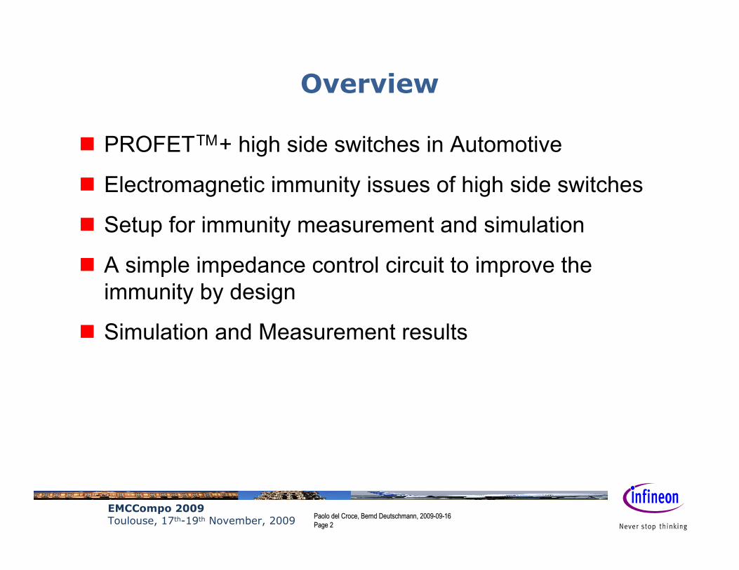
Overview
PROFETTM+ high side switches in Automotive
Electromagnetic immunity issues of high side switches
Setup for immunity measurement and simulation
A simple impedance control circuit to improve the immunity by design
Simulation and Measurement results
EMCCompo 2009Toulouse, 17th-19th November, 2009 Paolo del Croce, Bernd Deutschmann, 2009Paolo del Croce, Bernd Deutschmann, 2009--0909--16 16
Page Page 33
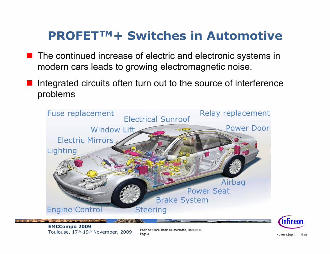
PROFETTM+ Switches in Automotive
The continued increase of electric and electronic systems in modern cars leads to growing electromagnetic noise.
Integrated circuits often turn out to the source of interferenceproblems
Airbag
Electric Mirrors
Power Door
Power Seat
Window Lift
Lighting
SteeringEngine ControlBrake System
Electrical SunroofRelay replacementFuse replacement
EMCCompo 2009Toulouse, 17th-19th November, 2009 Paolo del Croce, Bernd Deutschmann, 2009Paolo del Croce, Bernd Deutschmann, 2009--0909--16 16
Page Page 44
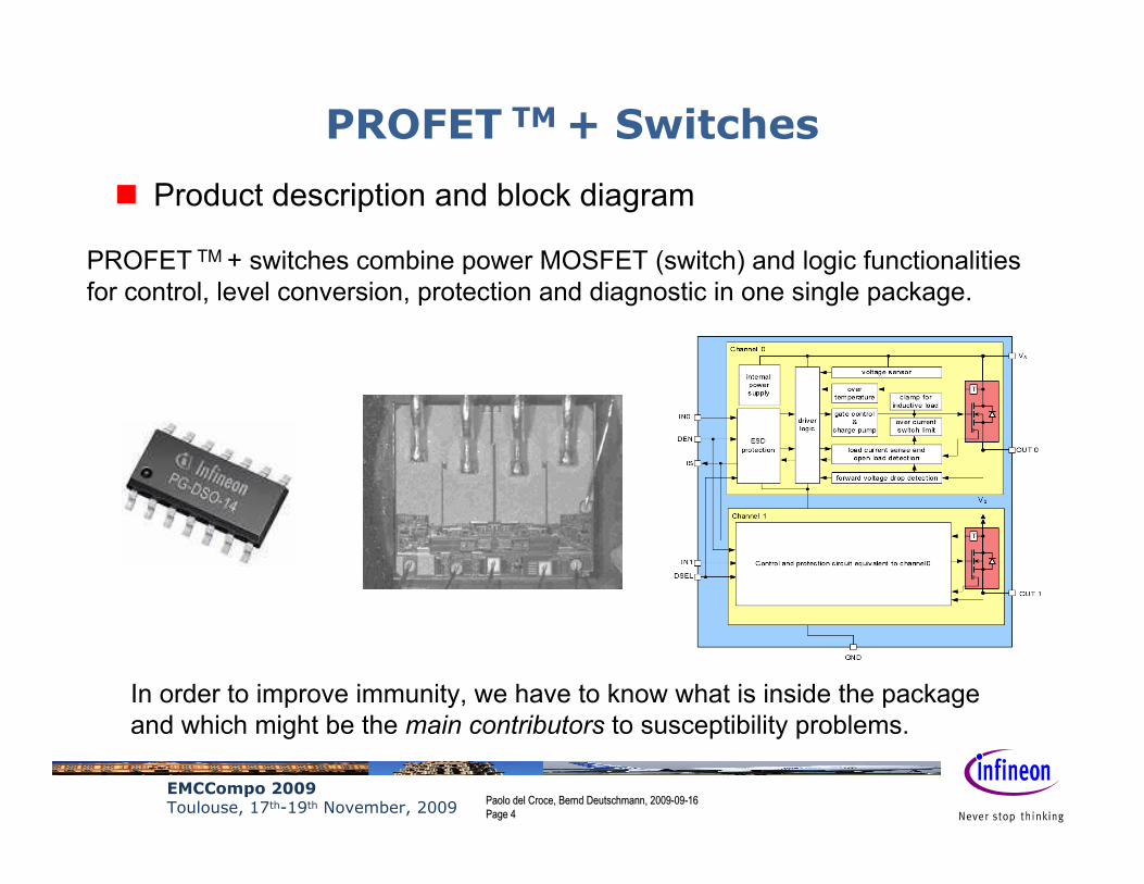
PROFET TM + Switches
Product description and block diagram
PROFET TM + switches combine power MOSFET (switch) and logic functionalitiesfor control, level conversion, protection and diagnostic in one single package.
In order to improve immunity, we have to know what is inside the package and which might be the main contributors to susceptibility problems.
EMCCompo 2009Toulouse, 17th-19th November, 2009 Paolo del Croce, Bernd Deutschmann, 2009Paolo del Croce, Bernd Deutschmann, 2009--0909--16 16
Page Page 55
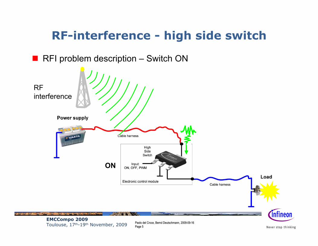
RF-interference - high side switch
RF interference
RFI problem description – Switch ON
ON

EMCCompo 2009Toulouse, 17th-19th November, 2009 Paolo del Croce, Bernd Deutschmann, 2009Paolo del Croce, Bernd Deutschmann, 2009--0909--16 16
Page Page 66
RF-interference - high side switch
RF interference
RFI problem description – Switch OFF
OFF

EMCCompo 2009Toulouse, 17th-19th November, 2009 Paolo del Croce, Bernd Deutschmann, 2009Paolo del Croce, Bernd Deutschmann, 2009--0909--16 16
Page Page 77
RF-interference - high side switch
RFI problem description – Signal at Vbat
V
t
Vbat
If the supply voltage goes below Vbat min. the full functionality can not be guaranteed anymore. If the supply voltage goes further below GND, substrate junctions get forward biased.
Vbat min.
EMCCompo 2009Toulouse, 17th-19th November, 2009 Paolo del Croce, Bernd Deutschmann, 2009Paolo del Croce, Bernd Deutschmann, 2009--0909--16 16
Page Page 88
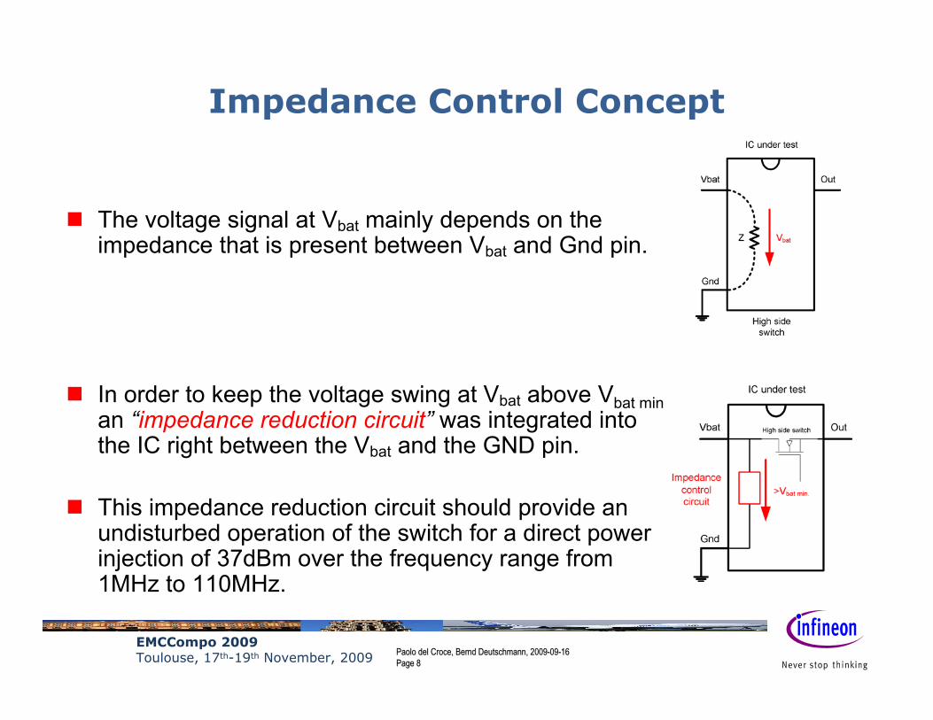
Impedance Control Concept
The voltage signal at Vbat mainly depends on the impedance that is present between Vbat and Gnd pin.
In order to keep the voltage swing at Vbat above Vbat minan “impedance reduction circuit” was integrated into the IC right between the Vbat and the GND pin.
This impedance reduction circuit should provide an undisturbed operation of the switch for a direct power injection of 37dBm over the frequency range from 1MHz to 110MHz.

EMCCompo 2009Toulouse, 17th-19th November, 2009 Paolo del Croce, Bernd Deutschmann, 2009Paolo del Croce, Bernd Deutschmann, 2009--0909--16 16
Page Page 99
DPI measurement setup according to IEC 62132-4
Setup for EMI Measurement

EMCCompo 2009Toulouse, 17th-19th November, 2009 Paolo del Croce, Bernd Deutschmann, 2009Paolo del Croce, Bernd Deutschmann, 2009--0909--16 16
Page Page 1010
DPI simulation setup according to IEC 62132-4
Setup for EMI Simulation

EMCCompo 2009Toulouse, 17th-19th November, 2009 Paolo del Croce, Bernd Deutschmann, 2009Paolo del Croce, Bernd Deutschmann, 2009--0909--16 16
Page Page 1111
Impedance Reduction Circuit
Circuit topology
56789
101112131415
1 10 100 1000Frequency (MHz)
Impe
danc
e (O
hm)
Circuit impedance over frequency
EMCCompo 2009Toulouse, 17th-19th November, 2009 Paolo del Croce, Bernd Deutschmann, 2009Paolo del Croce, Bernd Deutschmann, 2009--0909--16 16
Page Page 1212
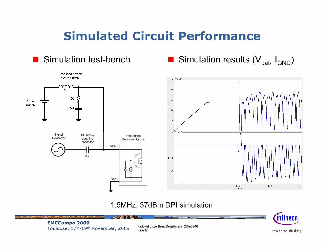
1.5MHz, 37dBm DPI simulation
Simulated Circuit Performance
Simulation test-bench Simulation results (Vbat, IGND)

EMCCompo 2009Toulouse, 17th-19th November, 2009 Paolo del Croce, Bernd Deutschmann, 2009Paolo del Croce, Bernd Deutschmann, 2009--0909--16 16
Page Page 1313
Simulated Product Behavior
1.5MHz, 37dBm DPI simulation
Simulation test-bench Simulation results (Vbat, IGND)
EMCCompo 2009Toulouse, 17th-19th November, 2009 Paolo del Croce, Bernd Deutschmann, 2009Paolo del Croce, Bernd Deutschmann, 2009--0909--16 16
Page Page 1414
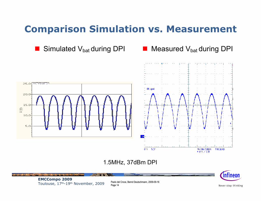
Comparison Simulation vs. Measurement
Simulated Vbat during DPI Measured Vbat during DPI
1.5MHz, 37dBm DPI
EMCCompo 2009Toulouse, 17th-19th November, 2009 Paolo del Croce, Bernd Deutschmann, 2009Paolo del Croce, Bernd Deutschmann, 2009--0909--16 16
Page Page 1515
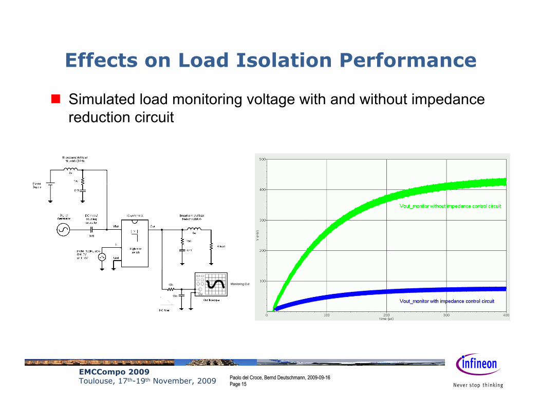
Effects on Load Isolation Performance
Simulated load monitoring voltage with and without impedance reduction circuit

EMCCompo 2009Toulouse, 17th-19th November, 2009 Paolo del Croce, Bernd Deutschmann, 2009Paolo del Croce, Bernd Deutschmann, 2009--0909--16 16
Page Page 1616
Immunity Test Results
Assessment of product robustness to DPI in off state
0
5
10
15
20
25
30
35
40
1 10 100 1000
f / MHz
dBm
OFF-Mode
max. test level
Device:Load:O-Mode:Coupling Point:Monitoring:Modulation:
IC under test3.3ΩOFFVbatOutCW
EMCCompo 2009Toulouse, 17th-19th November, 2009 Paolo del Croce, Bernd Deutschmann, 2009Paolo del Croce, Bernd Deutschmann, 2009--0909--16 16
Page Page 1717
Conclusion
An optimization methodology based on pin impedance control has been proposed and applied in the development of PROFET TM + switch products.
Simulation and measurement results have been compared to validate the approach.
Effectiveness of the methodology in the low frequency range has been confirmed.