Embed Size (px)
Citation preview
1
E 2.
804.
0/03
.17
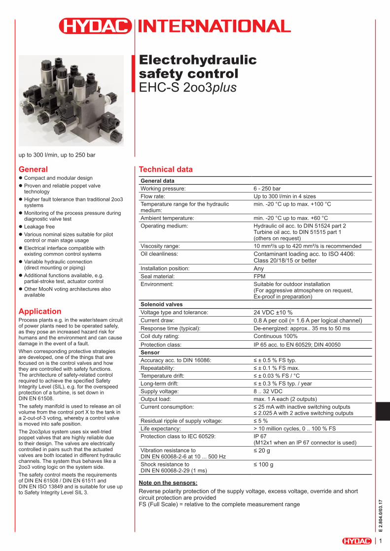
Electrohydraulic safety control EHC-S 2oo3plus
General z Compact and modular design z Proven and reliable poppet valve technology
z Higher fault tolerance than traditional 2oo3 systems
z Monitoring of the process pressure during diagnostic valve test
z Leakage free z Various nominal sizes suitable for pilot control or main stage usage
z Electrical interface compatible with existing common control systems
z Variable hydraulic connection (direct mounting or piping)
z Additional functions available, e.g. partial-stroke test, actuator control
z Other MooN voting architectures also available
ApplicationProcess plants e.g. in the water/steam circuit of power plants need to be operated safely, as they pose an increased hazard risk for humans and the environment and can cause damage in the event of a fault.When corresponding protective strategies are developed, one of the things that are focused on is the control valves and how they are controlled with safety functions. The architecture of safety-related control required to achieve the specified Safety Integrity Level (SIL), e.g. for the overspeed protection of a turbine, is set down in DIN EN 61508.The safety manifold is used to release an oil volume from the control port X to the tank in a 2-out-of-3 voting, whereby a control valve is moved into safe position.The 2oo3plus system uses six well-tried poppet valves that are highly reliable due to their design. The valves are electrically controlled in pairs such that the actuated valves are both located in different hydraulic channels. The system thus behaves like a 2oo3 voting logic on the system side. The safety control meets the requirements of DIN EN 61508 / DIN EN 61511 and DIN EN ISO 13849 and is suitable for use up to Safety Integrity Level SIL 3.
Technical dataGeneral dataWorking pressure: 6 - 250 bar Flow rate: Up to 300 l/min in 4 sizesTemperature range for the hydraulic medium:
min. -20 °C up to max. +100 °C
Ambient temperature: min. -20 °C up to max. +60 °COperating medium: Hydraulic oil acc. to DIN 51524 part 2
Turbine oil acc. to DIN 51515 part 1 (others on request)
Viscosity range: 10 mm²/s up to 420 mm²/s is recommendedOil cleanliness: Contaminant loading acc. to ISO 4406:
Class 20/18/15 or betterInstallation position: AnySeal material: FPMEnvironment: Suitable for outdoor installation
(For aggressive atmosphere on request, Ex-proof in preparation)
Solenoid valvesVoltage type and tolerance: 24 VDC ±10 %Current draw: 0.8 A per coil (= 1.6 A per logical channel)Response time (typical): De-energized: approx.. 35 ms to 50 msCoil duty rating: Continuous 100%Protection class: IP 65 acc. to EN 60529; DIN 40050SensorAccuracy acc. to DIN 16086: ≤ ± 0.5 % FS typ.Repeatability: ≤ ± 0.1 % FS max.Temperature drift: ≤ ± 0.03 % FS / °CLong-term drift: ≤ ± 0.3 % FS typ. / yearSupply voltage: 8 .. 32 VDCOutput load: max. 1 A each (2 outputs)Current consumption: ≤ 25 mA with inactive switching outputs
≤ 2.025 A with 2 active switching outputsResidual ripple of supply voltage: ≤ 5 %Life expectancy: > 10 million cycles, 0 .. 100 % FSProtection class to IEC 60529: IP 67
(M12x1 when an IP 67 connector is used)Vibration resistance to DIN EN 60068-2-6 at 10 ... 500 Hz
≤ 20 g
Shock resistance to DIN EN 60068-2-29 (1 ms)
≤ 100 g
up to 300 l/min, up to 250 bar
Note on the sensors:Reverse polarity protection of the supply voltage, excess voltage, override and short circuit protection are provided FS (Full Scale) = relative to the complete measurement range
2
E 2.
804.
0/03
.17
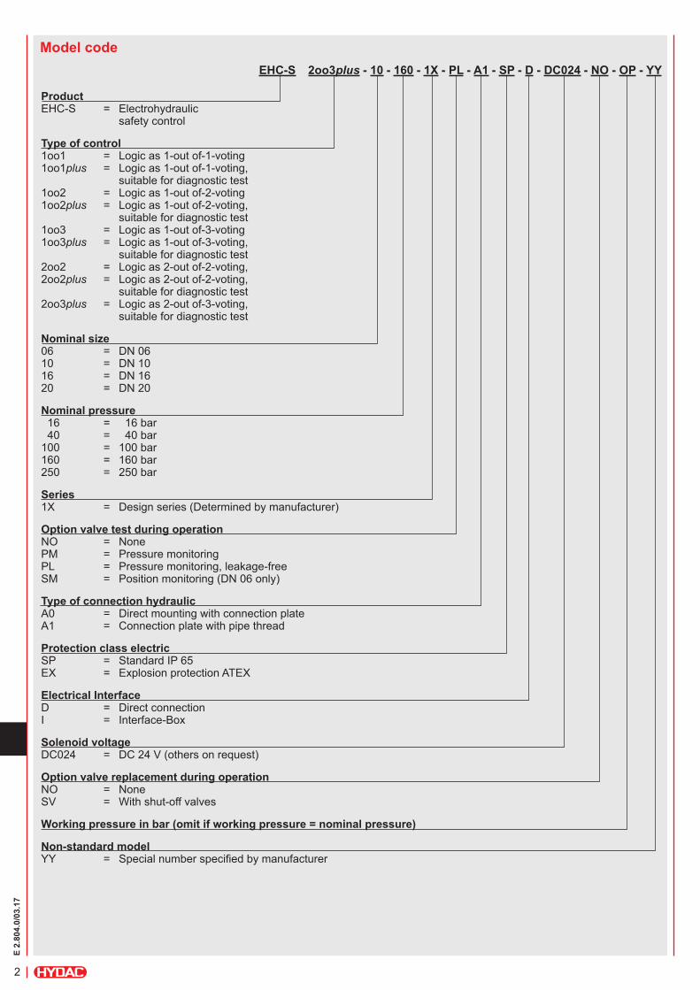
Model codeEHC-S 2oo3plus - 10 - 160 - 1X - PL - A1 - SP - D - DC024 - NO - OP - YY
Product EHC-S = Electrohydraulic safety control
Type of control 1oo1 = Logic as 1-out of-1-voting 1oo1plus = Logic as 1-out of-1-voting, suitable for diagnostic test 1oo2 = Logic as 1-out of-2-voting 1oo2plus = Logic as 1-out of-2-voting, suitable for diagnostic test 1oo3 = Logic as 1-out of-3-voting 1oo3plus = Logic as 1-out of-3-voting, suitable for diagnostic test 2oo2 = Logic as 2-out of-2-voting, 2oo2plus = Logic as 2-out of-2-voting, suitable for diagnostic test 2oo3plus = Logic as 2-out of-3-voting, suitable for diagnostic test
Nominal size 06 = DN 06 10 = DN 10 16 = DN 16 20 = DN 20
Nominal pressure 16 = 16 bar 40 = 40 bar 100 = 100 bar 160 = 160 bar 250 = 250 bar
Series 1X = Design series (Determined by manufacturer)
Option valve test during operation NO = None PM = Pressure monitoring PL = Pressure monitoring, leakage-free SM = Position monitoring (DN 06 only)
Type of connection hydraulic A0 = Direct mounting with connection plate A1 = Connection plate with pipe thread
Protection class electric SP = Standard IP 65 EX = Explosion protection ATEX
Electrical Interface D = Direct connection I = Interface-Box
Solenoid voltage DC024 = DC 24 V (others on request)
Option valve replacement during operation NO = None SV = With shut-off valves
Working pressure in bar (omit if working pressure = nominal pressure)
Non-standard model YY = Special number specified by manufacturer
3
E 2.
804.
0/03
.17
Model range
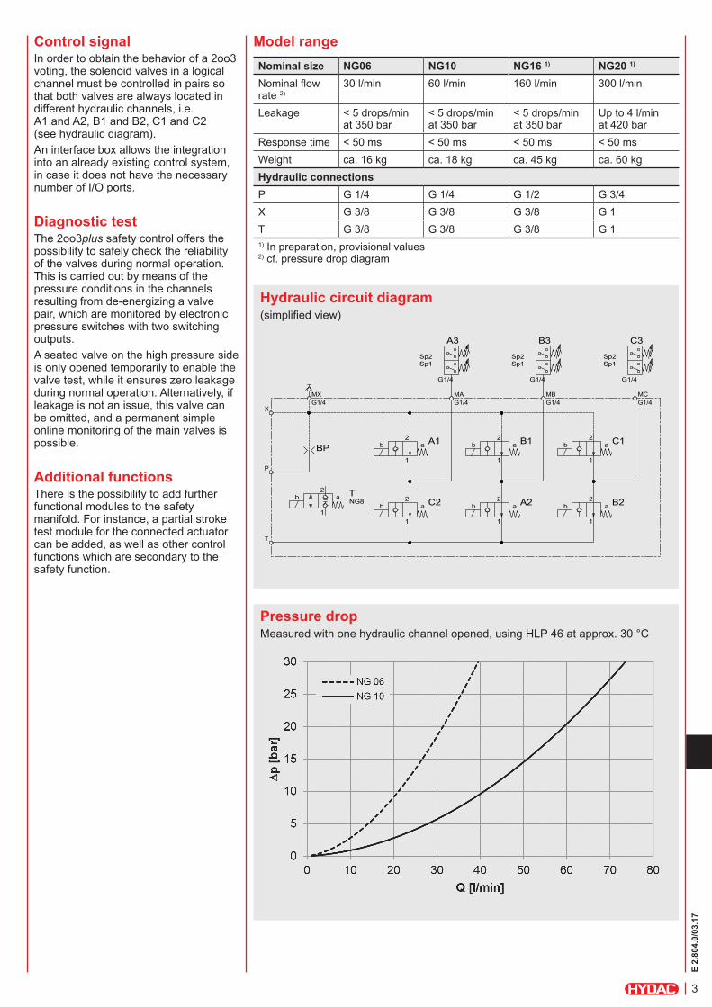
Hydraulic circuit diagram
Pressure drop
Control signalIn order to obtain the behavior of a 2oo3 voting, the solenoid valves in a logical channel must be controlled in pairs so that both valves are always located in different hydraulic channels, i.e. A1 and A2, B1 and B2, C1 and C2 (see hydraulic diagram).An interface box allows the integration into an already existing control system, in case it does not have the necessary number of I/O ports.
Diagnostic testThe 2oo3plus safety control offers the possibility to safely check the reliability of the valves during normal operation. This is carried out by means of the pressure conditions in the channels resulting from de-energizing a valve pair, which are monitored by electronic pressure switches with two switching outputs.A seated valve on the high pressure side is only opened temporarily to enable the valve test, while it ensures zero leakage during normal operation. Alternatively, if leakage is not an issue, this valve can be omitted, and a permanent simple online monitoring of the main valves is possible.
Additional functionsThere is the possibility to add further functional modules to the safety manifold. For instance, a partial stroke test module for the connected actuator can be added, as well as other control functions which are secondary to the safety function.
Nominal size NG06 NG10 NG16 1) NG20 1)
Nominal flow rate 2)
30 l/min 60 l/min 160 l/min 300 l/min
Leakage < 5 drops/min at 350 bar
< 5 drops/min at 350 bar
< 5 drops/min at 350 bar
Up to 4 l/min at 420 bar
Response time < 50 ms < 50 ms < 50 ms < 50 msWeight ca. 16 kg ca. 18 kg ca. 45 kg ca. 60 kgHydraulic connectionsP G 1/4 G 1/4 G 1/2 G 3/4X G 3/8 G 3/8 G 3/8 G 1T G 3/8 G 3/8 G 3/8 G 11) In preparation, provisional values2) cf. pressure drop diagram
BP
G1/4
Sp1Sp2
A3
G1/4
Sp1Sp2
B3
G1/4
Sp1Sp2
C3
b a2
1
A1 b a2
1
B1 b a2
1
C1
b a2
1
B2b a2
1
A2b a2
1
C2b a
2
1
NG8
T
X
P
T
MXG1/4
MAG1/4
MBG1/4
MCG1/4
Measured with one hydraulic channel opened, using HLP 46 at approx. 30 °C
(simplified view)
4
E 2.
804.
0/03
.17
NoteThe information in this brochure relates to the operating conditions and applications described.For applications or operating conditions not described, please contact the relevant technical department.Subject to technical modifications.
HYDAC SYSTEM GMBHIndustriegebiet D-66280 Sulzbach / Saar Tel.:+49 (0) 6897/509-0 Fax:+49 (0) 6897/509-303 Internet: www.hydac.com E-Mail: [email protected]
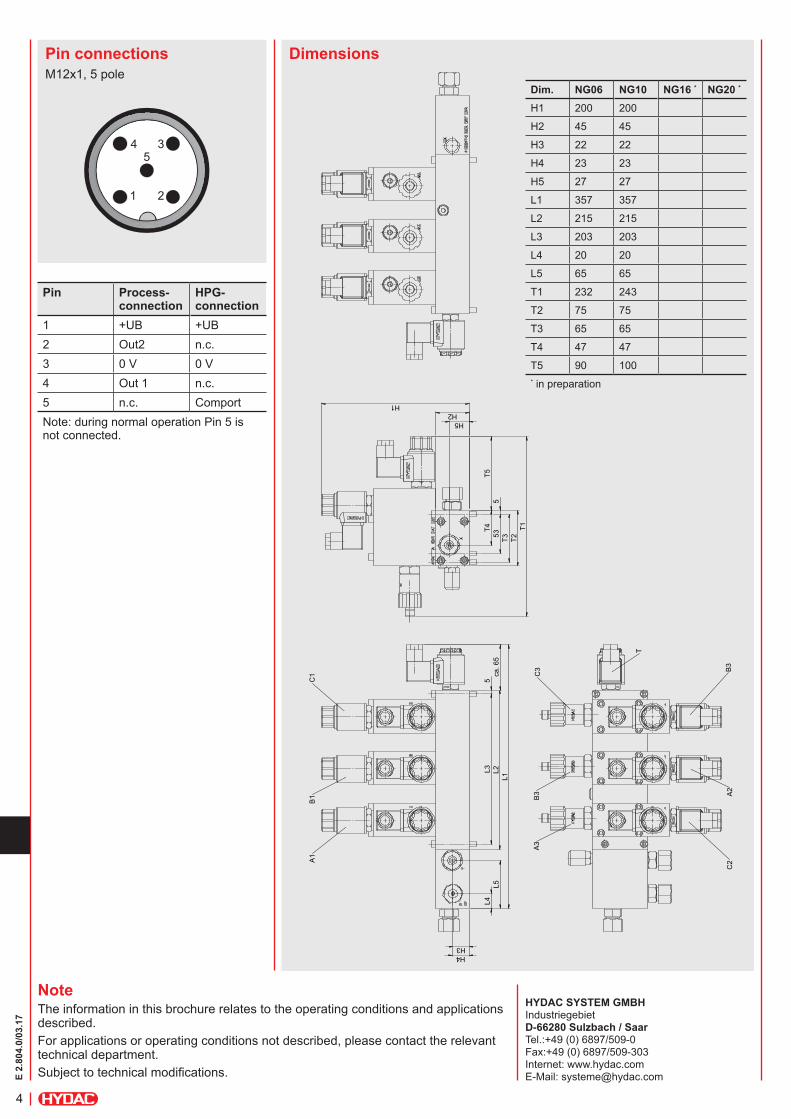
DimensionsPin connectionsM12x1, 5 pole
Pin Process- connection
HPG- connection
1 +UB +UB2 Out2 n.c.3 0 V 0 V4 Out 1 n.c.5 n.c. ComportNote: during normal operation Pin 5 is not connected.
Dim. NG06 NG10 NG16 * NG20 *
H1 200 200
H2 45 45
H3 22 22
H4 23 23
H5 27 27
L1 357 357
L2 215 215
L3 203 203
L4 20 20
L5 65 65
T1 232 243
T2 75 75
T3 65 65
T4 47 47
T5 90 100* in preparation
T1
H1
T2
H5 H2
T5
5
53
T3 T
4 L
2 L
3 5
ca.
65
L1
L4
L5
H3 H4
A1
B1
C1
A3
B3
C3
C2
A2
B3
T
1 2
345


![Cleaning Validation (2010[1].03.17) [호환 모드]](https://img.pdfslide.us/doc/110x75/61c459d34325ab4c8c1a09d5/cleaning-validation-201010317-.jpg)
![Sam jae portfolio [03.17].compressed](https://img.pdfslide.us/doc/110x75/58cf02131a28abab738b6947/sam-jae-portfolio-0317compressed.jpg)