Embed Size (px)
Citation preview
Defence R&D Canada – Atlantic
DEFENCE DÉFENSE&
Electrochemical SupercapacitorsSecond Annual Report
Michael S. FreundGraeme SuppesBhavana DeoreUniversity of Manitoba
University of ManitobaDepartment of ChemistryWinnipeg, Manitoba R3T 2N2
Project Manager: Michael S. Freund, 204-474 -8772
Contract Number: W7707-063349
Contract Scientific Authority: Colin G. Cameron, 902-427-1367
The scientific or technical validity of this Contract Report is entirely the responsibility of the contractorand the contents do not necessarily have the approval or endorsement of Defence R&D Canada.
Contract Report
DRDC Atlantic CR 2008-125
September 2008
Copy No. _____
Defence Research andDevelopment Canada
Recherche et développementpour la défense Canada

This page intentionally left blank.
Electrochemical SupercapacitorsSecond Annual Report
Michael S. FreundUniversity of Manitoba
Graeme SuppesUniversity of Manitoba
Bhavana DeoreUniversity of Manitoba
Prepared by:
University of ManitobaDepartment of ChemistryWinnipeg MB R3T 2N2
Project Manager: Michael S. Freund 204-474-8772Contract Number: W7707-063349Contract Scientific Authority: Colin G. Cameron 902-427-1367
The scientific or technical validity of this Contract Report is entirely the responsibility of the contractorand the contents do not necessarily have the approval or endorsement of Defence R&D Canada.
Defence R&D Canada – AtlanticContract ReportDRDC Atlantic CR 2008-125September 2008
Approved by
Leon ChengA/SH DL(A)
Approved for release by
James L. KennedyChair/Document Review Panel
c© Her Majesty the Queen in Right of Canada as represented by the Minister of NationalDefence, 2008
c© Sa Majeste la Reine (en droit du Canada), telle que representee par le ministre de laDefense nationale, 2008
Original signed by Leon Cheng
Original signed by Ron Kuwahara for
Abstract
This report summarizes results from the second year of this three year project in develop-ing supercapacitor electrode materials based on conducting polymers. Work has contin-ued using the controlled growth polymerization method to manipulate porosity in films ofpolypyrrole. It was found that composites of polypyrrole and multiwalled carbon nano-tubes had an ionic conductivity two orders of magnitude greater than the polypyrrole filmsalone. Polypyrrole films on carbon cloth were also examined and found to possess en-hanced stability if the polymer is built-up in layers. Finally, preliminary results indicatethat conducting polymer films containing phosphotungstic acid may serve well as the neg-ative electrode in an asymmetric capacitor.
Resume
Ce rapport traite des resultats provenant de la deuxieme annee d’un projet que vise adevelopper de nouveaux materiaux bases sur les polymeres conducteurs pour les electrodesde supercondensateur. On a continue a utiliser la methode de polymerisation controlee pourmanipuler la porosite des feuilles minces de polypyrrole. On a decouvert que les materiauxcomposites de polypyrrole et nanotube de carbone multiparoi possedent une conductiviteionique cent fois plus elevee que celle de polypyrrole pur. De plus, des feuilles mincesde polypyrrole sur tissu carbone ont ete examinees et on a trouve qu’elles demontrentune stabilite augmentee quand elles sont formees en couches. Par ailleurs des resultatspreliminaires indiquent que les polymeres conducteurs contentant l’acide phosphotungs-tique pourrait servir comme electrode negatif dans un supercondensateur asymetrique.
DRDC Atlantic CR 2008-125 i

This page intentionally left blank.
ii DRDC Atlantic CR 2008-125
Executive summary
Electrochemical Supercapacitors: Second AnnualReport
Michael S. Freund, Graeme Suppes, Bhavana Deore; DRDC Atlantic CR2008-125; Defence R&D Canada – Atlantic; September 2008.
Background: This Technology Investment Fund (TIF) program aims to develop improvedsupercapacitor technology through the design of better electrode materials. This will ulti-mately yield devices with elevated power and energy densities and/or performance custom-tailored to the needs of the Canadian military. The present work represents one branch ofthe program, where supercapacitor electrodes are being developed from conducting poly-mers and composites. Conducting polymers are a class of material with good charge stor-age capacity which can be enhanced further by the inclusion of electroactive clusters. How-ever, their performance as capacitor electrodes tends to be hampered by slow ion transport.
Principal Results: This work continues to exploit the controlled growth polymerizationmethod to develop new conducting polymer-based materials. New results arose in three keyareas: (i) Polypyrrole composites containing MWCNTs (Multi-walled carbon nanotubes)exhibit a porous morphology, even in the absence of the supplementary porogen demon-strated in the previous year’s report. Electrochemical response goes through a maximum ataround 8% MWCNT content, exhibiting for example a 100-fold increase in ionic conduc-tivity compared to the polymer alone; (ii) Carbon paper coated with polypyrrole in multiplelayers shows somewhat slower response but enhanced stability. At a 1 mA/cm2 discharge,specific power and energy densities were, respectively, 103 W/kg and 1.9 Wh/kg; (iii) Pre-liminary experiments with asymmetric capacitors where one electrodes incorporates phos-photungstic acid indicate that a significant increase in the voltage range may be achieved.
Significance: The results of the past year indicate progress towards tailoring this type ofmaterial for use in supercapacitors. Improving the ionic conductivity is critically impor-tant to increasing the power density of the electrode material. Broadening of the potentialwindow will increase the energy density of the device as the square of the voltage; conse-quently, the development of new negative electrode materials is of great interest.
Future Work: Future work will include: (i) attempts to elucidate why two waves in thecyclic voltammogram grow out of a single one in the symmetric capacitor, (ii) continu-ing to improve the ionic conductivity of the polypyrrole/phosphomolybdic acid materials,and (iii) further developing the phosphotungstic acid electrode and incorporating it in anasymmetric capacitor.
DRDC Atlantic CR 2008-125 iii
Sommaire
Electrochemical Supercapacitors: Second AnnualReport
Michael S. Freund, Graeme Suppes, Bhavana Deore ; DRDC Atlantic CR2008-125 ; R & D pour la defense Canada – Atlantique ; septembre 2008.
Contexte : Ce programme de fonds d’investissement technologique vise a developper demeilleurs technologies de supercondensateur par concevoir de meilleurs materiaux d’elec-trode. Ceci donnera enfin des supercondensateurs a densites de puissance et d’energieelevees, et des dispositifs personnalises pour les forces canadiennes. Le present œuvrerepresente une partie du programme, ou on developpe des electrodes basees sur les po-lymeres conducteurs et ses composites. En general les polymeres conducteurs ont une ca-pacite de charge assez elevee et qui peut etre augmentee davantage en ajoutant des agregatselectroactifs. Toutefois leur fonctionnement comme electrode de supercondensateurs estsouvent limite par le migration lent des ions.
Resultats principaux : On continue a exploiter la methode de polymerisation controleepour developper de nouveaux materiaux bases sur les polymeres conducteurs. Les resultatsprincipaux incluent : (i) Les composites de polypyrrole et nanotubes de carbone multiparoi(NTCMP) ont une morphologie poreuse, meme sans les agents progenes decrits dans ledernier rapport annuel ; (ii) Du papier carbone traite de plusieurs couches demontre unereponse plus lente mais plus stable. Au cours d’une decharge de 1 mA/cm2, la puissance etl’energie specific etaient 103 W/kg et 1.9 Wh/kg, respectivement ; (iii) Nos experiencespreliminaires avec des supercondensateurs asymetriques dont un electrode est traite del’acide phosphotungstique indiquent qu’une gamme de voltage etendue est fort possible.
Portee : Les resultats de cette annee decrient du progres envers la personnalisation de cegenre de materiau pour les supercondensateurs. Il est tres important d’ameliorer la conduc-tivite ionique pour augmenter la densite de puissance. Etendre la gamme de voltage nousdonnera une densite d’energie augmentee ; en consequence le developpement des nouveauxmateriaux pour l’electrode negatif est important.
Recherches futures : Les recherches futures incluront : (i) un effort a decouvrir pourquoiune vague electrochimique devient deux dans le supercondensateur symetrique, (ii) conti-nuer davantage a ameliorer la conductivite ionique de polypyrrole, et (iii) elaborer l’elec-trode de l’acide phosphotungstique et l’utiliser dans un supercondensateur asymetrique.
iv DRDC Atlantic CR 2008-125
Table of contents
Abstract . . . . . . . . . . . . . . . . . . . . . . . . . . . . . . . . . . . . . . . . . i
Resume . . . . . . . . . . . . . . . . . . . . . . . . . . . . . . . . . . . . . . . . . i
Executive summary . . . . . . . . . . . . . . . . . . . . . . . . . . . . . . . . . . . iii
Sommaire . . . . . . . . . . . . . . . . . . . . . . . . . . . . . . . . . . . . . . . . iv
Table of contents . . . . . . . . . . . . . . . . . . . . . . . . . . . . . . . . . . . . v
List of figures . . . . . . . . . . . . . . . . . . . . . . . . . . . . . . . . . . . . . . vii
List of tables . . . . . . . . . . . . . . . . . . . . . . . . . . . . . . . . . . . . . . . ix
1 Background . . . . . . . . . . . . . . . . . . . . . . . . . . . . . . . . . . . . . 1
2 Experimental . . . . . . . . . . . . . . . . . . . . . . . . . . . . . . . . . . . . 2
2.1 Materials . . . . . . . . . . . . . . . . . . . . . . . . . . . . . . . . . . . 2
2.2 Synthesis of PPy/PMA/Carbon Nanotube Composites . . . . . . . . . . . 2
2.3 Synthesis of PPy/PMA Films on Carbon Paper . . . . . . . . . . . . . . . 2
2.4 Construction of the Capacitor Cell . . . . . . . . . . . . . . . . . . . . . 3
2.5 Characterization Techniques . . . . . . . . . . . . . . . . . . . . . . . . . 3
2.5.1 Cyclic voltammetry . . . . . . . . . . . . . . . . . . . . . . . . . 3
2.5.2 Impedance spectroscopy . . . . . . . . . . . . . . . . . . . . . . 4
2.5.3 Scanning electron microscopy . . . . . . . . . . . . . . . . . . . 4
3 Results and Discussion . . . . . . . . . . . . . . . . . . . . . . . . . . . . . . . 4
3.1 Characterization of PPy/PMA/Carbon Nanotubes Composites . . . . . . . 4
3.1.1 Conductivity . . . . . . . . . . . . . . . . . . . . . . . . . . . . 4
3.1.2 Morphology . . . . . . . . . . . . . . . . . . . . . . . . . . . . 5
3.1.3 Redox behaviour . . . . . . . . . . . . . . . . . . . . . . . . . . 6
3.1.4 Specific capacitance . . . . . . . . . . . . . . . . . . . . . . . . 6
DRDC Atlantic CR 2008-125 v
3.1.5 Switching speed . . . . . . . . . . . . . . . . . . . . . . . . . . 8
3.1.6 Impedance measurements . . . . . . . . . . . . . . . . . . . . . 11
3.2 Characterization of PPy/PMA Films Coated on Carbon Paper . . . . . . . 13
3.2.1 Redox behaviour . . . . . . . . . . . . . . . . . . . . . . . . . . 13
3.2.2 Switching speed . . . . . . . . . . . . . . . . . . . . . . . . . . 13
3.2.3 Morphology . . . . . . . . . . . . . . . . . . . . . . . . . . . . 14
3.2.4 Redox stability . . . . . . . . . . . . . . . . . . . . . . . . . . . 14
3.2.5 Specific capacitance . . . . . . . . . . . . . . . . . . . . . . . . 16
3.3 Swagelok Capacitor Cell Using PPy/PMA Composite Films . . . . . . . . 18
3.3.1 Redox behaviour . . . . . . . . . . . . . . . . . . . . . . . . . . 18
3.3.2 Specific capacitance, energy, and power . . . . . . . . . . . . . . 19
3.4 Extending the Potential Window with Phosphotungstic Acid . . . . . . . . 20
4 Conclusion . . . . . . . . . . . . . . . . . . . . . . . . . . . . . . . . . . . . . 22
5 Future work . . . . . . . . . . . . . . . . . . . . . . . . . . . . . . . . . . . . . 23
Symbols and Abbreviations . . . . . . . . . . . . . . . . . . . . . . . . . . . . . . . 24
References . . . . . . . . . . . . . . . . . . . . . . . . . . . . . . . . . . . . . . . . 25
vi DRDC Atlantic CR 2008-125
List of figures
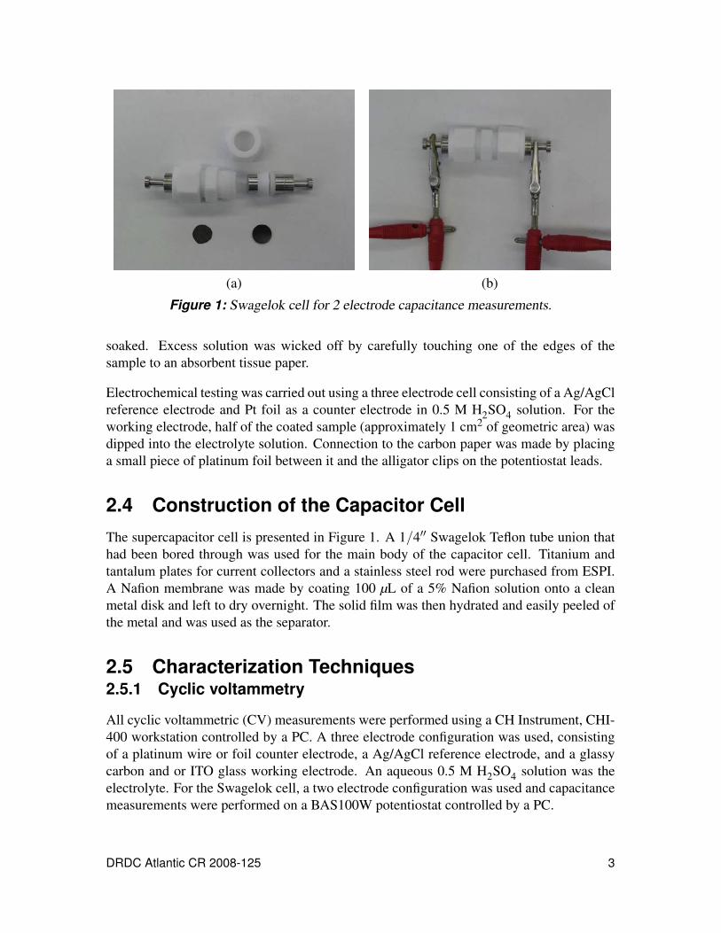
Figure 1: Swagelok cell for 2 electrode capacitance measurements. . . . . . . . . . 3
Figure 2: Conductivity vs. % w/w of MWCNTs in PPy/PMA composite films.Films were prepared using 25.15 mg/ml of pyrrole and 342.3 mg/ml ofPMA in THF. . . . . . . . . . . . . . . . . . . . . . . . . . . . . . . . . 5
Figure 3: PPy/PMA films with 8% MWCNTs at (a) ×1000, and (b) ×10,000magnification. Nanotubes were dispersed in a solution of PMA in THF.Films prepared using 2.5 mg/ml pyrrole and 34.23 mg/ml PMA in THF. . 6
Figure 4: Cyclic voltammograms of chemically prepared PPy/PMA compositefilm with different amounts of MWCNTs at GC electrode in 0.5 MH2SO4 at a scan rate of 100 mV/s: (a) 0%, (b) 2%, (c) 5%, (d) 8%, and(e) 10% w/w. Films were prepared using 2.5 mg/ml (37.5 mM) pyrroleand 34.23 mg/ml (18.75 mM) PMA in THF. . . . . . . . . . . . . . . . 7
Figure 5: Specific capacitance of chemically preparedpolypyrrole/PMA/MWCNTs composite film (a) without and (b) withporogens (40 mg/ml) on an ITO electrode in 0.5 M H2SO4 at a scanrate of 10 mV/s. Films prepared using 25 mg/ml pyrrole, 342.2 mg/mlPMA + 8% MWCNTs, with and without sodium sulphate in THF. . . . . 7
Figure 6: Cyclic voltammograms and peak current (second oxidation peak) as afunction of scan rate of chemically prepared PPy/PMA composite filmwithout and with 8% MWCNTs and sodium sulphate at GC electrodein 0.5 M H2SO4 at different scan rate (10 mV/s – 20 V/s); (a) porousPPy/PMA film with 4 mg/ml sodium sulphate, (b) non-porousPPy/PMA film with 8% MWCNTs and (c) porous PPy/PMA film with4 mg/ml sodium sulphate and 8% MWCNT. Films were prepared using2.5 mg/ml pyrrole and 34.2 mg/ml PMA THF. . . . . . . . . . . . . . . 9
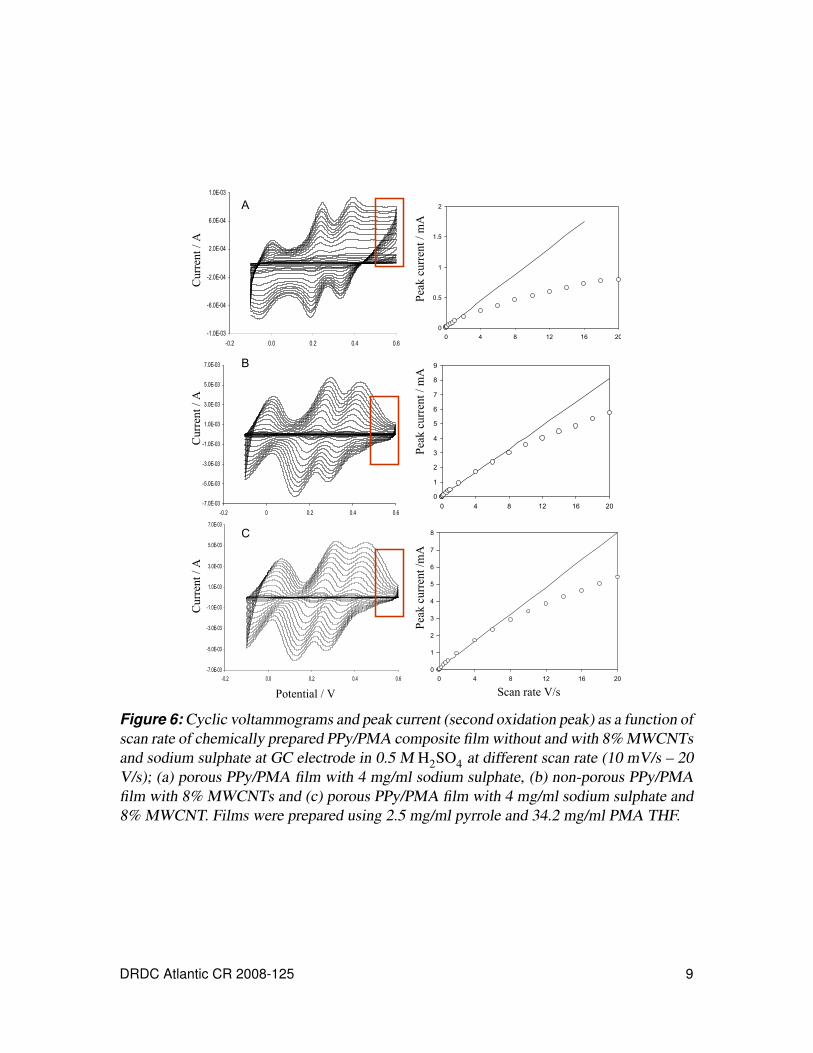
Figure 7: Cyclic voltammograms chemically prepared PPy/PMA composite filmwithout and with 8% MWCNTs and sodium sulphate at GC electrodein 0.5 M H2SO4 at different scan rate; (a) porous PPy/PMA film with 4mg/ml sodium sulphate, (b) non-porous PPy/PMA film with 8%MWCNTs and (c) porous PPy/PMA film with 4 mg/ml sodiumsulphate and 8% MWCNT. Films were prepared using 2.5 mg/ml(37.5 mM) pyrrole and 34.2 mg/ml (18.75 mM) PMA in THF. Scanrate: (A) 0.01 V/s, (B) 0.1 V/s, (C) 1 V/s, and (D) 10 V/s. . . . . . . . . 10
DRDC Atlantic CR 2008-125 vii
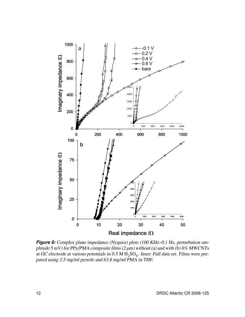
Figure 8: Complex plane impedance (Nyquist) plots (100 KHz–0.1 Hz,perturbation amplitude 5 mV) for PPy/PMA composite films (2 µm)without (a) and with (b) 8% MWCNTs at GC electrode at variouspotentials in 0.5 M H2SO4. Inset: Full data set. Films were preparedusing 2.5 mg/ml pyrrole and 63.8 mg/ml PMA in THF. . . . . . . . . . . 12
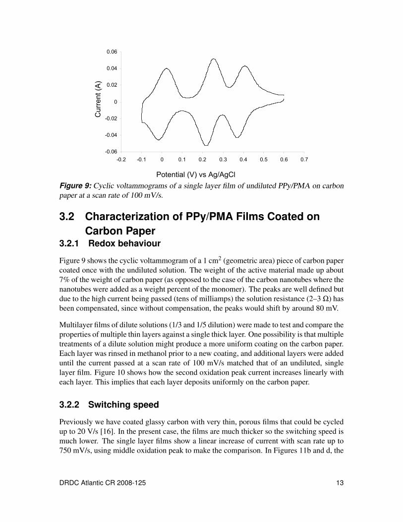
Figure 9: Cyclic voltammograms of a single layer film of undiluted PPy/PMA oncarbon paper at a scan rate of 100 mV/s. . . . . . . . . . . . . . . . . . . 13
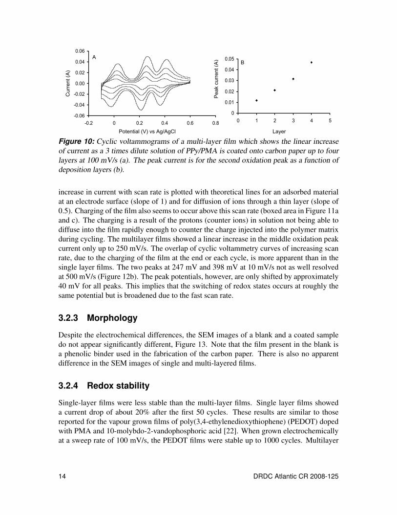
Figure 10: Cyclic voltammograms of a multi-layer film which shows the linearincrease of current as a 3 times dilute solution of PPy/PMA is coatedonto carbon paper up to four layers at 100 mV/s (a). The peak current isfor the second oxidation peak as a function of deposition layers (b). . . . 14
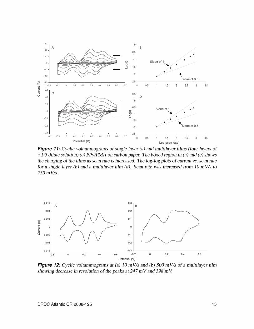
Figure 11: Cyclic voltammograms of single layer (a) and multilayer films (fourlayers of a 1:3 dilute solution) (c) PPy/PMA on carbon paper. Theboxed region in (a) and (c) shows the charging of the films as scan rateis increased. The log-log plots of current vs. scan rate for a single layer(b) and a multilayer film (d). Scan rate was increased from 10 mV/s to750 mV/s. . . . . . . . . . . . . . . . . . . . . . . . . . . . . . . . . . 15
Figure 12: Cyclic voltammograms at (a) 10 mV/s and (b) 500 mV/s of a multilayerfilm showing decrease in resolution of the peaks at 247 mV and 398 mV. 15
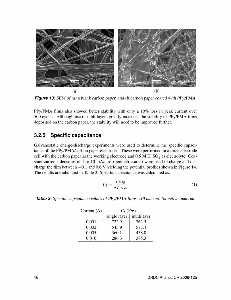
Figure 13: SEM of (a) a blank carbon paper, and (b)carbon paper coated withPPy/PMA. . . . . . . . . . . . . . . . . . . . . . . . . . . . . . . . . . 16
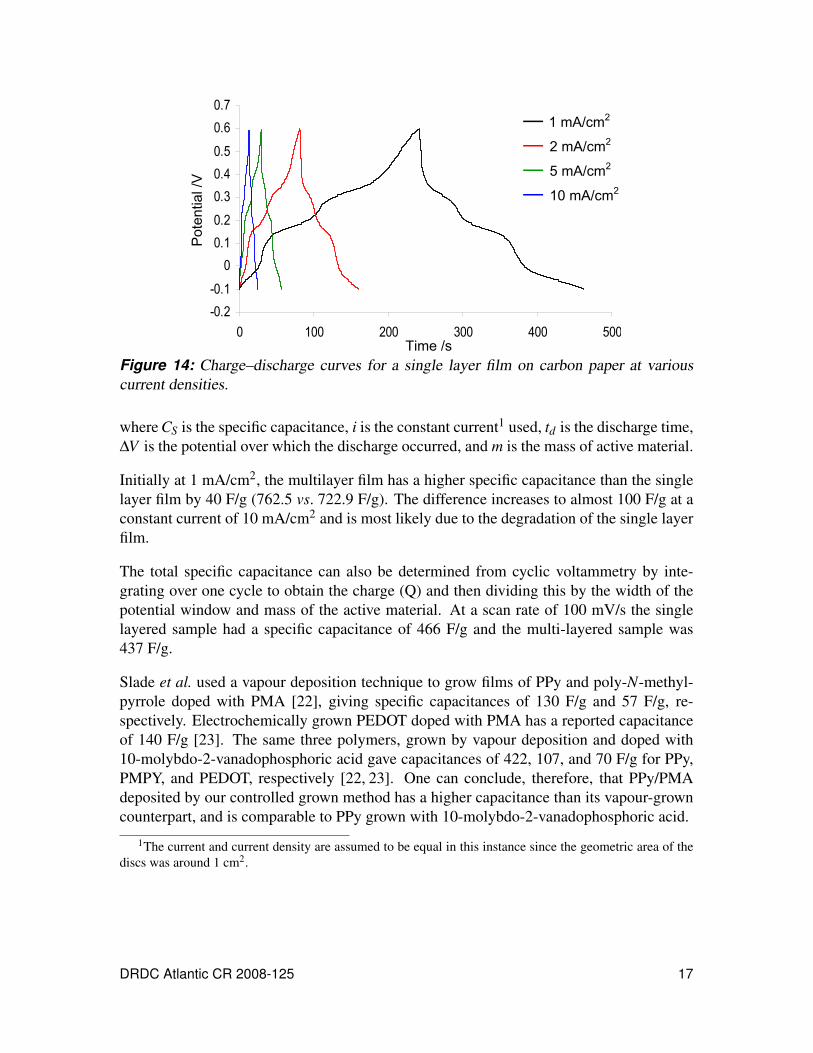
Figure 14: Charge–discharge curves for a single layer film on carbon paper atvarious current densities. . . . . . . . . . . . . . . . . . . . . . . . . . . 17
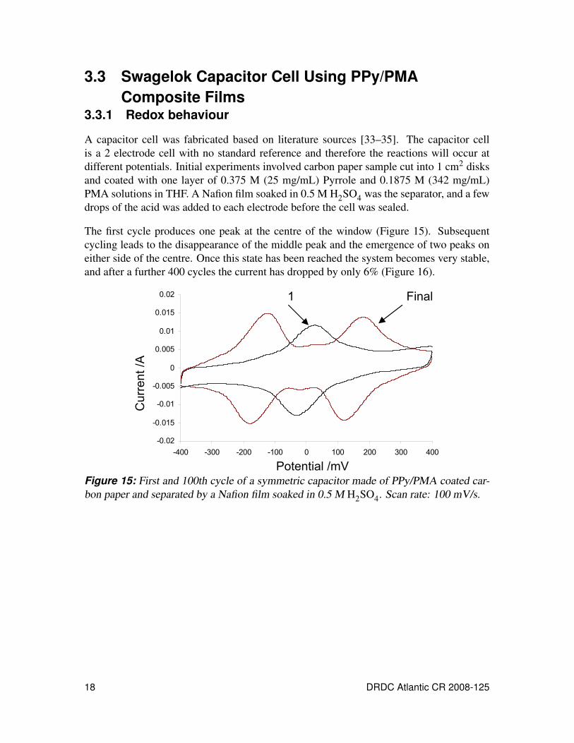
Figure 15: First and 100th cycle of a symmetric capacitor made of PPy/PMAcoated carbon paper and separated by a Nafion film soaked in 0.5 MH2SO4. Scan rate: 100 mV/s. . . . . . . . . . . . . . . . . . . . . . . . 18
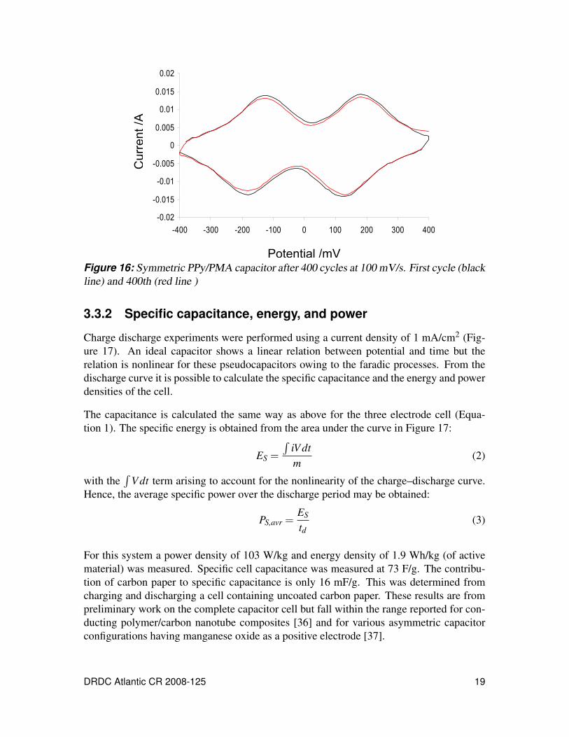
Figure 16: Symmetric PPy/PMA capacitor after 400 cycles at 100 mV/s. Firstcycle (black line) and 400th (red line ) . . . . . . . . . . . . . . . . . . . 19
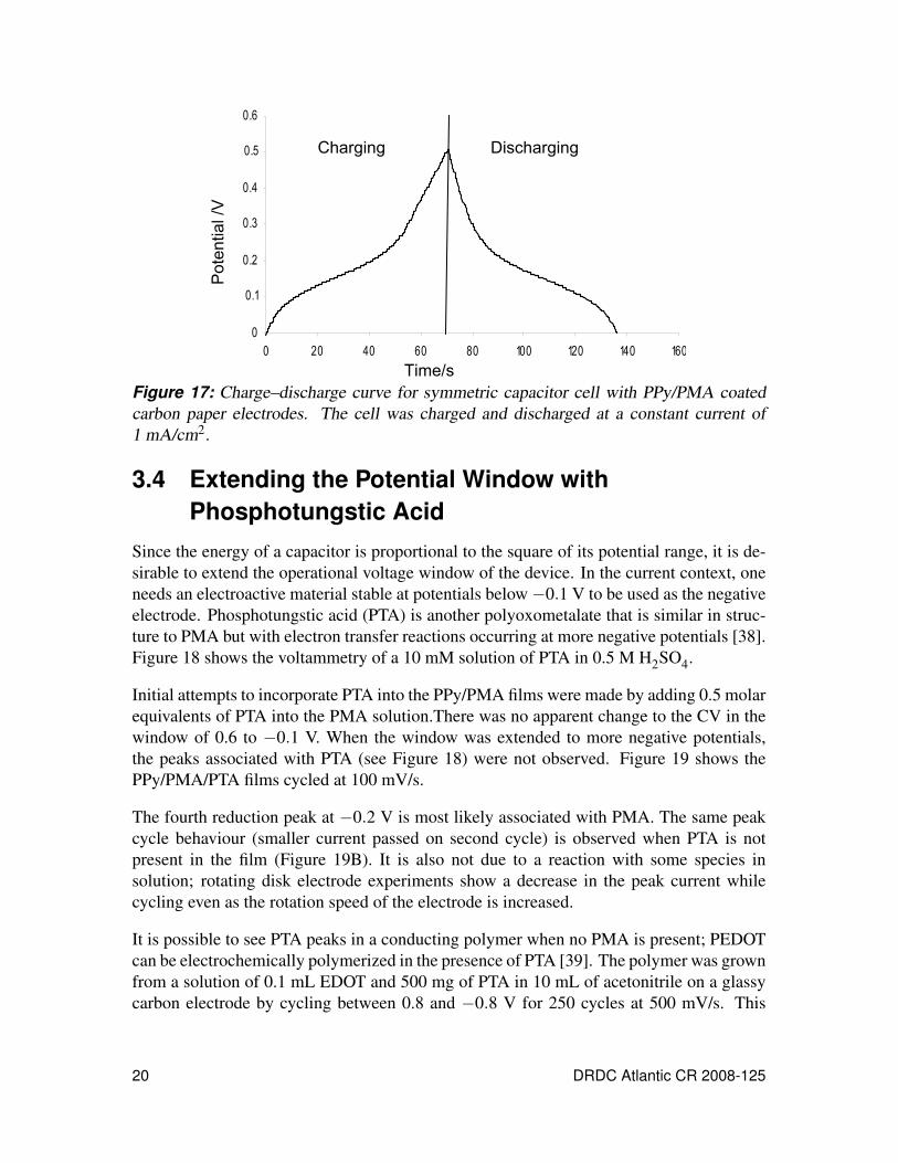
Figure 17: Charge–discharge curve for symmetric capacitor cell with PPy/PMAcoated carbon paper electrodes. The cell was charged and discharged ata constant current of 1 mA/cm2. . . . . . . . . . . . . . . . . . . . . . . 20
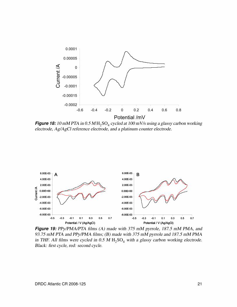
Figure 18: 10 mM PTA in 0.5 M H2SO4 cycled at 100 mV/s using a glassy carbonworking electrode, Ag/AgCl reference electrode, and a platinumcounter electrode. . . . . . . . . . . . . . . . . . . . . . . . . . . . . . 21
viii DRDC Atlantic CR 2008-125
Figure 19: PPy/PMA/PTA films (A) made with 375 mM pyrrole, 187.5 mM PMA,and 93.75 mM PTA and PPy/PMA films; (B) made with 375 mMpyrrole and 187.5 mM PMA in THF. All films were cycled in 0.5 MH2SO4 with a glassy carbon working electrode. Black: first cycle, red:second cycle. . . . . . . . . . . . . . . . . . . . . . . . . . . . . . . . . 21
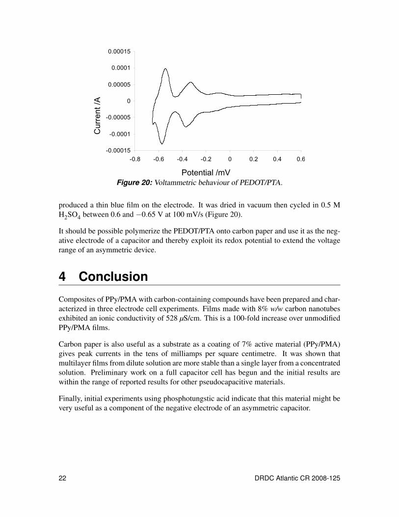
Figure 20: Voltammetric behaviour of PEDOT/PTA. . . . . . . . . . . . . . . . . . 22
List of tables
Table 1: Ionic conductivities from impedance spectroscopy of PPy/PMAcomposite films (2 µm) prepared with and without porogen anddifferent amount of MWCNTs at various potentials in 0.5 M H2SO4 . . . 11
Table 2: Specific capacitance values of PPy/PMA films. All data are for activematerial. . . . . . . . . . . . . . . . . . . . . . . . . . . . . . . . . . . 16
DRDC Atlantic CR 2008-125 ix

This page intentionally left blank.
x DRDC Atlantic CR 2008-125
1 Background
The interest in supercapacitors arises from applications that demand transient bursts ofpower and/or for hybrid systems when coupled with a lower power source such as a fuelcell. High-surface-area carbons [1, 2], metal oxides [3, 4], and conducting polymers [4–8]are examples of commonly used supercapacitor electrode materials, all of which lead toenergy densities higher than those found in conventional parallel-plate capacitors. Con-ducting polymers are particularly attractive due to the fast electrochemical switching andthe potential for synthetic modification. A further advantage is that one may add elec-troactive molecular clusters or extended inorganic species to form hybrid materials thatoffer improved stability, better charge propagation dynamics, and enhanced storage capac-ity [9–11].
It has been reported that thin films of polypyrrole (PPy) can be generated on variety ofsurfaces when a heteropolyoxometalate such as phosphomolybdic acid (PMA) is used asan oxidant [12–15]. In addition to this it is also possible to introduce a porogen into themonomer/oxidant solution, prior to coating, which may be dissolved from the polymer.We have shown previously that a water soluble sodium salt can be used to produce porouspolymer films [16]. Increasing the porosity of the composite films increased the rate atwhich the redox state of the polymer can be switched. This behaviour was attributed to anincrease in the ionic conductivity and a lowering of the RC time constant of the material.However, in highly porous PPy/PMA composite films (i.e., films prepared using higherconcentrations of salt), a degradation in switching response is observed. This was presum-ably due to increased internal resistance associated with fewer conductive pathways withinthe highly porous material. Therefore, we hypothesized that a conducting carbon materialsuch as carbon nanotubes (CNTs) can be embedded within highly porous PPy/PMA com-posite films in order to reduce the internal resistance by providing additional conductivepathways.
In recent years, CNTs have seen numerous applications in chemo/biosensors and catalysis.Recently, CNTs modified with Keggin-type polyoxometalates have been used for bromatesensors [17], methanol electrooxidation [18], and catalysts for hydrogen evolution [19].Polyoxometalates are known for their ability to adsorb on common solid electrode sub-strates, especially on carbon-based materials including powders, fibres and nanotubes withpromising efficiencies and high immobilization strength [17, 18, 20]. Electrodes modifiedwith a mixture of polyoxometalates,PPy, and CNTs have been used for the detection ofnitrite [21]. In this report, we use multi walled CNTs (MWCNTs) as a conducting fillerand to increase PMA loading in the PPy composites.
Previously Slade et al. have shown that carbon paper can be coated with conducting poly-mer/polyoxometalates [22–24] using a monomer vapour deposition technique. Such coat-ings can also be produced using the monomer oxidant solution method works, givinggreater capacitance, as will be presented in this report.
DRDC Atlantic CR 2008-125 1
2 Experimental2.1 MaterialsPhosphomolybdic acid hydrate (H3PMo12O40), pyrrole, tetrahydrofuran (THF), phospho-tungstic acid, 3,4-ethylenedioxythiophene, and MWCNTs were purchased from Aldrichand used without any further purification. Glassy carbon electrodes (3 mm diameter) werepurchased from CHI. Indium-doped tin oxide (ITO, 6±2Ω/square) glass slides were pur-chased from Delta Technologies, Limited. Bulk distilled water was filtered then ion ex-changed using Milli-Q-Academic A10 (Millipore Corporation) to yield 18.2 MΩ·cm qual-ity water. Carbon paper (2050-A) was purchased from Spectracarb.
2.2 Synthesis of PPy/PMA/Carbon NanotubeComposites
PPy/PMA/MWCNTs composites were prepared as follows: Two vials were prepared, eachcontaining a known and roughly equal volume of THF. To one, a sufficient quantity ofpyrrole was added so that the its concentration would be 375 mM (25 mg/mL) after thevials were mixed. Similarly, PMA was added to second vial to give an ultimate concen-tration of 187.5 mM (342 mg/mL), along with a predetermined quantity of MWCNTs inaccordance with the desired composite formulation. The PMA+MWCNT solution wassonicated for four hours, and then the solutions were combined. The MWCNTs were welldispersed in the THF in the presence of PMA and they produced a stable black suspension.The PMA molecules are adsorbed on the surface of MWCNTs by spontaneous and strongchemisorption, which creates a distribution of negative charges that prevents the aggre-gation of MWCNTs [25, 26]. The films were chemically synthesized by spin coating thereaction mixture onto ITO at 2000 RPM for 10 seconds. Upon completion of the spin coat-ing process, films were then left to dry at room temperature overnight before rinsing withmethanol to remove unreacted material and reduced PMA. The films were subsequentlyleft to dry before characterization.
PPy/PMA composite films were prepared on glassy carbon (GC) electrodes by adding 5 µLof reaction mixture to the surface of the electrode.
2.3 Synthesis of PPy/PMA Films on Carbon PaperSimilarly to the MWCNT composites (Section 2.2), samples were prepared from a solutioncontaining 25 mg/ml of pyrrole and 342 mg/ml of PMA in THF, and from 1/3 and 1/5dilutions of this solution. 1×2 cm carbon paper strips were cut from a larger sheet.
After mixing, the solution was dripped onto the carbon paper until the paper was thoroughly
2 DRDC Atlantic CR 2008-125
(a) (b)
Figure 1: Swagelok cell for 2 electrode capacitance measurements.
soaked. Excess solution was wicked off by carefully touching one of the edges of thesample to an absorbent tissue paper.
Electrochemical testing was carried out using a three electrode cell consisting of a Ag/AgClreference electrode and Pt foil as a counter electrode in 0.5 M H2SO4 solution. For theworking electrode, half of the coated sample (approximately 1 cm2 of geometric area) wasdipped into the electrolyte solution. Connection to the carbon paper was made by placinga small piece of platinum foil between it and the alligator clips on the potentiostat leads.
2.4 Construction of the Capacitor CellThe supercapacitor cell is presented in Figure 1. A 1/4′′ Swagelok Teflon tube union thathad been bored through was used for the main body of the capacitor cell. Titanium andtantalum plates for current collectors and a stainless steel rod were purchased from ESPI.A Nafion membrane was made by coating 100 µL of a 5% Nafion solution onto a cleanmetal disk and left to dry overnight. The solid film was then hydrated and easily peeled ofthe metal and was used as the separator.
2.5 Characterization Techniques2.5.1 Cyclic voltammetry
All cyclic voltammetric (CV) measurements were performed using a CH Instrument, CHI-400 workstation controlled by a PC. A three electrode configuration was used, consistingof a platinum wire or foil counter electrode, a Ag/AgCl reference electrode, and a glassycarbon and or ITO glass working electrode. An aqueous 0.5 M H2SO4 solution was theelectrolyte. For the Swagelok cell, a two electrode configuration was used and capacitancemeasurements were performed on a BAS100W potentiostat controlled by a PC.
DRDC Atlantic CR 2008-125 3
2.5.2 Impedance spectroscopy
Impedance measurements were made using a Solartron 1287 electrochemical interfaceand 1255B frequency response analyzer. Impedance measurements were conducted usingZPlot software with perturbation amplitude of 5 mV over a frequency range of 100 kHz to0.01 Hz, 10 points per decade. A three electrode configuration was used, consisting of aplatinum wire counter electrode, a Ag/AgCl reference electrode, and a glassy carbon work-ing electrode. Two electrode measurements were made using the Swagelok cell, connectedso that the counter and reference were connected to one side (negative terminal) and theworking and secondary reference were connected to the other (positive terminal).
2.5.3 Scanning electron microscopy
The micrographs of the composite films were taken by a JEOL 5900 IVAN-LV scanningelectron microscope (SEM).
3 Results and Discussion3.1 Characterization of PPy/PMA/Carbon Nanotubes
Composites3.1.1 Conductivity
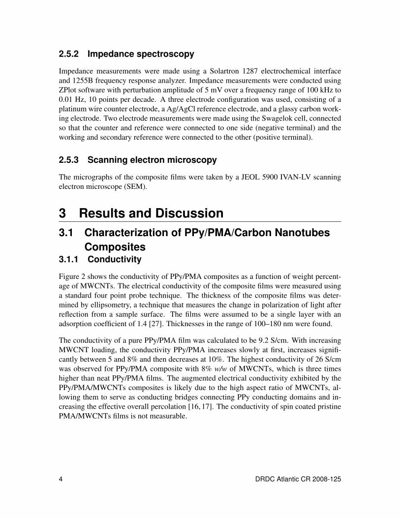
Figure 2 shows the conductivity of PPy/PMA composites as a function of weight percent-age of MWCNTs. The electrical conductivity of the composite films were measured usinga standard four point probe technique. The thickness of the composite films was deter-mined by ellipsometry, a technique that measures the change in polarization of light afterreflection from a sample surface. The films were assumed to be a single layer with anadsorption coefficient of 1.4 [27]. Thicknesses in the range of 100–180 nm were found.
The conductivity of a pure PPy/PMA film was calculated to be 9.2 S/cm. With increasingMWCNT loading, the conductivity PPy/PMA increases slowly at first, increases signifi-cantly between 5 and 8% and then decreases at 10%. The highest conductivity of 26 S/cmwas observed for PPy/PMA composite with 8% w/w of MWCNTs, which is three timeshigher than neat PPy/PMA films. The augmented electrical conductivity exhibited by thePPy/PMA/MWCNTs composites is likely due to the high aspect ratio of MWCNTs, al-lowing them to serve as conducting bridges connecting PPy conducting domains and in-creasing the effective overall percolation [16, 17]. The conductivity of spin coated pristinePMA/MWCNTs films is not measurable.
4 DRDC Atlantic CR 2008-125
% Weight of MWCNT
Co
ndu
ctivity S
/cm
0
5
10
15
20
25
30
0 2 4 6 8 10 1
% Weight of MWCNT
Co
ndu
ctivity S
/cm
2
0
5
10
15
20
25
30
0 2 4 6 8 10 12
Figure 2: Conductivity vs. % w/w of MWCNTs in PPy/PMA composite films. Films wereprepared using 25.15 mg/ml of pyrrole and 342.3 mg/ml of PMA in THF.
3.1.2 Morphology
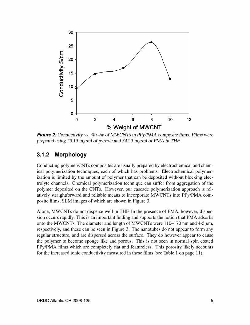
Conducting polymer/CNTs composites are usually prepared by electrochemical and chem-ical polymerization techniques, each of which has problems. Electrochemical polymer-ization is limited by the amount of polymer that can be deposited without blocking elec-trolyte channels. Chemical polymerization technique can suffer from aggregation of thepolymer deposited on the CNTs. However, our cascade polymerization approach is rel-atively straightforward and reliable means to incorporate MWCNTs into PPy/PMA com-posite films, SEM images of which are shown in Figure 3.
Alone, MWCNTs do not disperse well in THF. In the presence of PMA, however, disper-sion occurs rapidly. This is an important finding and supports the notion that PMA adsorbsonto the MWCNTs. The diameter and length of MWCNTs were 110–170 nm and 4-5 µm,respectively, and these can be seen in Figure 3. The nanotubes do not appear to form anyregular structure, and are dispersed across the surface. They do however appear to causethe polymer to become sponge like and porous. This is not seen in normal spin coatedPPy/PMA films which are completely flat and featureless. This porosity likely accountsfor the increased ionic conductivity measured in these films (see Table 1 on page 11).
DRDC Atlantic CR 2008-125 5
(a) (b)
Figure 3: PPy/PMA films with 8% MWCNTs at (a) ×1000, and (b) ×10,000 magnifica-tion. Nanotubes were dispersed in a solution of PMA in THF. Films prepared using 2.5mg/ml pyrrole and 34.23 mg/ml PMA in THF.
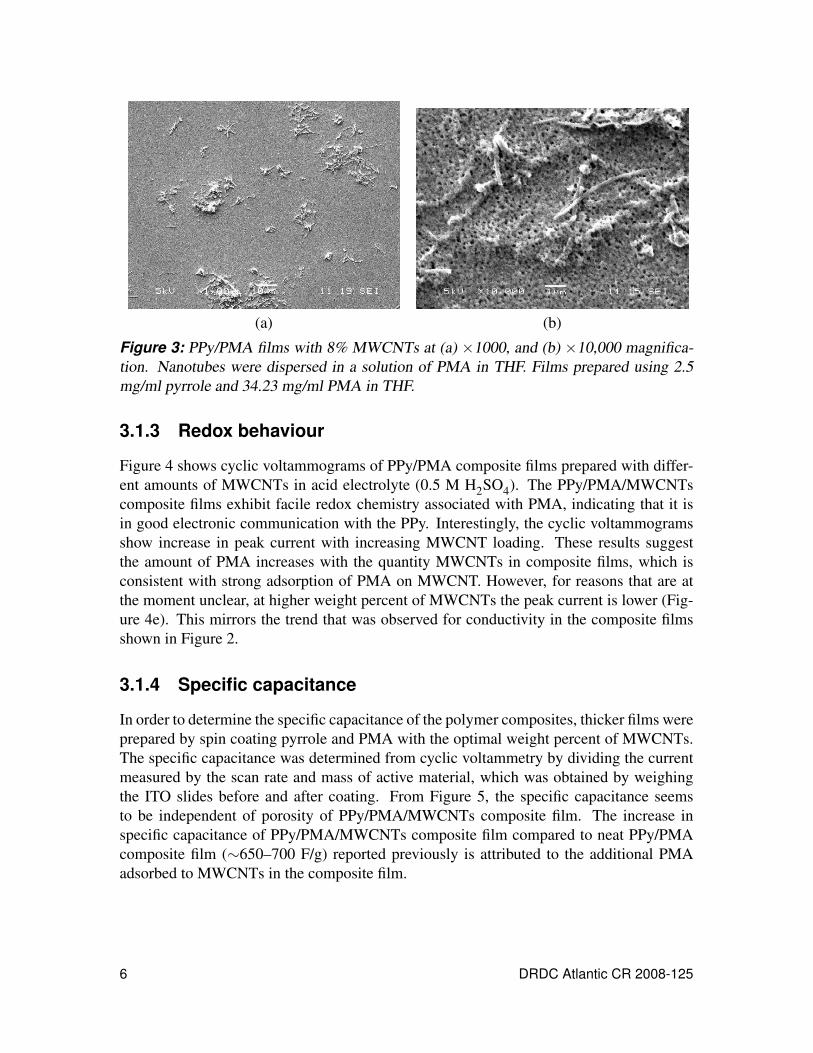
3.1.3 Redox behaviour
Figure 4 shows cyclic voltammograms of PPy/PMA composite films prepared with differ-ent amounts of MWCNTs in acid electrolyte (0.5 M H2SO4). The PPy/PMA/MWCNTscomposite films exhibit facile redox chemistry associated with PMA, indicating that it isin good electronic communication with the PPy. Interestingly, the cyclic voltammogramsshow increase in peak current with increasing MWCNT loading. These results suggestthe amount of PMA increases with the quantity MWCNTs in composite films, which isconsistent with strong adsorption of PMA on MWCNT. However, for reasons that are atthe moment unclear, at higher weight percent of MWCNTs the peak current is lower (Fig-ure 4e). This mirrors the trend that was observed for conductivity in the composite filmsshown in Figure 2.
3.1.4 Specific capacitance
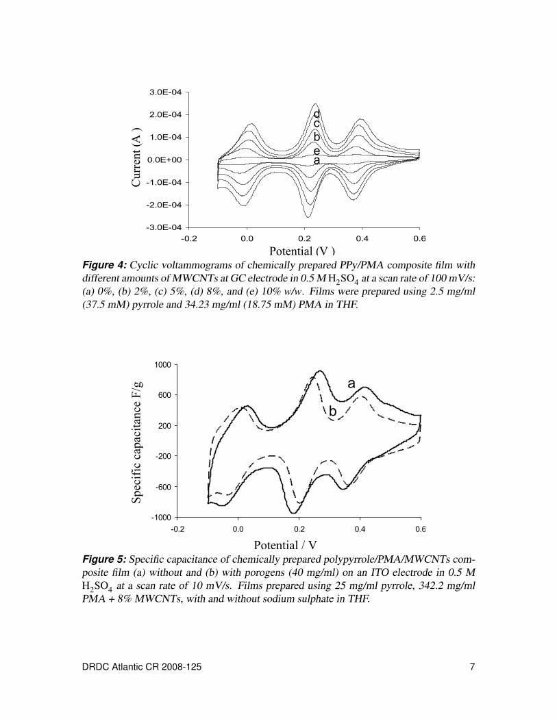
In order to determine the specific capacitance of the polymer composites, thicker films wereprepared by spin coating pyrrole and PMA with the optimal weight percent of MWCNTs.The specific capacitance was determined from cyclic voltammetry by dividing the currentmeasured by the scan rate and mass of active material, which was obtained by weighingthe ITO slides before and after coating. From Figure 5, the specific capacitance seemsto be independent of porosity of PPy/PMA/MWCNTs composite film. The increase inspecific capacitance of PPy/PMA/MWCNTs composite film compared to neat PPy/PMAcomposite film (∼650–700 F/g) reported previously is attributed to the additional PMAadsorbed to MWCNTs in the composite film.
6 DRDC Atlantic CR 2008-125
-3.0E-04
-2.0E-04
-1.0E-04
0.0E+00
1.0E-04
2.0E-04
3.0E-04
-0.2 0.0 0.2 0.4 0.6
a
cd
e
bC
urr
ent
(A
)
Potential (V )Figure 4: Cyclic voltammograms of chemically prepared PPy/PMA composite film withdifferent amounts of MWCNTs at GC electrode in 0.5 M H2SO4 at a scan rate of 100 mV/s:(a) 0%, (b) 2%, (c) 5%, (d) 8%, and (e) 10% w/w. Films were prepared using 2.5 mg/ml(37.5 mM) pyrrole and 34.23 mg/ml (18.75 mM) PMA in THF.
Sp
ecif
ic c
apac
itan
ce F
/g
-1000
-600
-200
200
600
1000
-0.2 0.0 0.2 0.4 0.6
Potential / V
a
b
Figure 5: Specific capacitance of chemically prepared polypyrrole/PMA/MWCNTs com-posite film (a) without and (b) with porogens (40 mg/ml) on an ITO electrode in 0.5 MH2SO4 at a scan rate of 10 mV/s. Films prepared using 25 mg/ml pyrrole, 342.2 mg/mlPMA + 8% MWCNTs, with and without sodium sulphate in THF.
DRDC Atlantic CR 2008-125 7
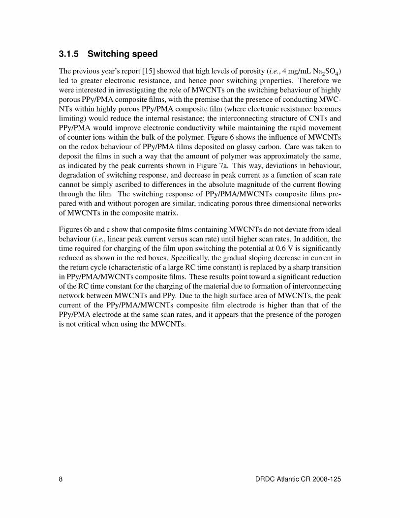
3.1.5 Switching speed
The previous year’s report [15] showed that high levels of porosity (i.e., 4 mg/mL Na2SO4)led to greater electronic resistance, and hence poor switching properties. Therefore wewere interested in investigating the role of MWCNTs on the switching behaviour of highlyporous PPy/PMA composite films, with the premise that the presence of conducting MWC-NTs within highly porous PPy/PMA composite film (where electronic resistance becomeslimiting) would reduce the internal resistance; the interconnecting structure of CNTs andPPy/PMA would improve electronic conductivity while maintaining the rapid movementof counter ions within the bulk of the polymer. Figure 6 shows the influence of MWCNTson the redox behaviour of PPy/PMA films deposited on glassy carbon. Care was taken todeposit the films in such a way that the amount of polymer was approximately the same,as indicated by the peak currents shown in Figure 7a. This way, deviations in behaviour,degradation of switching response, and decrease in peak current as a function of scan ratecannot be simply ascribed to differences in the absolute magnitude of the current flowingthrough the film. The switching response of PPy/PMA/MWCNTs composite films pre-pared with and without porogen are similar, indicating porous three dimensional networksof MWCNTs in the composite matrix.
Figures 6b and c show that composite films containing MWCNTs do not deviate from idealbehaviour (i.e., linear peak current versus scan rate) until higher scan rates. In addition, thetime required for charging of the film upon switching the potential at 0.6 V is significantlyreduced as shown in the red boxes. Specifically, the gradual sloping decrease in current inthe return cycle (characteristic of a large RC time constant) is replaced by a sharp transitionin PPy/PMA/MWCNTs composite films. These results point toward a significant reductionof the RC time constant for the charging of the material due to formation of interconnectingnetwork between MWCNTs and PPy. Due to the high surface area of MWCNTs, the peakcurrent of the PPy/PMA/MWCNTs composite film electrode is higher than that of thePPy/PMA electrode at the same scan rates, and it appears that the presence of the porogenis not critical when using the MWCNTs.
8 DRDC Atlantic CR 2008-125
-1.0E-03
-6.0E-04
-2.0E-04
2.0E-04
6.0E-04
1.0E-03
-0.2 0.0 0.2 0.4 0.6
Curr
ent
/ A
Potential / V
0
0.5
1
1.5
2
0 4 8 12 16
Scan rate V/s
Peak c
urr
ent
/ m
A
20
-7.0E-03
-5.0E-03
-3.0E-03
-1.0E-03
1.0E-03
3.0E-03
5.0E-03
7.0E-03
-0.2 0.0 0.2 0.4 0.6
Curr
ent
/ A
0
1
2
3
4
5
6
7
8
0 4 8 12 16
Peak c
urr
ent
/mA
20
-7.0E-03
-5.0E-03
-3.0E-03
-1.0E-03
1.0E-03
3.0E-03
5.0E-03
7.0E-03
-0.2 0 0.2 0.4 0.6
0
1
2
3
4
5
6
7
8
9
0 4 8 12 16 20
Curr
ent
/ A
Peak c
urr
ent
/ m
A
A
B
C
Figure 6: Cyclic voltammograms and peak current (second oxidation peak) as a function ofscan rate of chemically prepared PPy/PMA composite film without and with 8% MWCNTsand sodium sulphate at GC electrode in 0.5 M H2SO4 at different scan rate (10 mV/s – 20V/s); (a) porous PPy/PMA film with 4 mg/ml sodium sulphate, (b) non-porous PPy/PMAfilm with 8% MWCNTs and (c) porous PPy/PMA film with 4 mg/ml sodium sulphate and8% MWCNT. Films were prepared using 2.5 mg/ml pyrrole and 34.2 mg/ml PMA THF.
DRDC Atlantic CR 2008-125 9
-9.0E-06
-6.0E-06
-3.0E-06
0.0E+00
3.0E-06
6.0E-06
9.0E-06
-0.2 0.0 0.2 0.4 0.6
-7.0E-05
-5.0E-05
-3.0E-05
-1.0E-05
1.0E-05
3.0E-05
5.0E-05
7.0E-05
-0.2 0.0 0.2 0.4 0.6
-6.0E-04
-3.0E-04
0.0E+00
3.0E-04
6.0E-04
-0.2 0.0 0.2 0.4 0.6
-4.0E-03
-2.0E-03
0.0E+00
2.0E-03
4.0E-03
-0.2 0.0 0.2 0.4 0.6
A B
CD
Cu
rren
t /
A
Cu
rren
t /
A
a
b
c
Potential / V
Figure 7: Cyclic voltammograms chemically prepared PPy/PMA composite film withoutand with 8% MWCNTs and sodium sulphate at GC electrode in 0.5 M H2SO4 at differ-ent scan rate; (a) porous PPy/PMA film with 4 mg/ml sodium sulphate, (b) non-porousPPy/PMA film with 8% MWCNTs and (c) porous PPy/PMA film with 4 mg/ml sodiumsulphate and 8% MWCNT. Films were prepared using 2.5 mg/ml (37.5 mM) pyrrole and34.2 mg/ml (18.75 mM) PMA in THF. Scan rate: (A) 0.01 V/s, (B) 0.1 V/s, (C) 1 V/s, and(D) 10 V/s.
10 DRDC Atlantic CR 2008-125
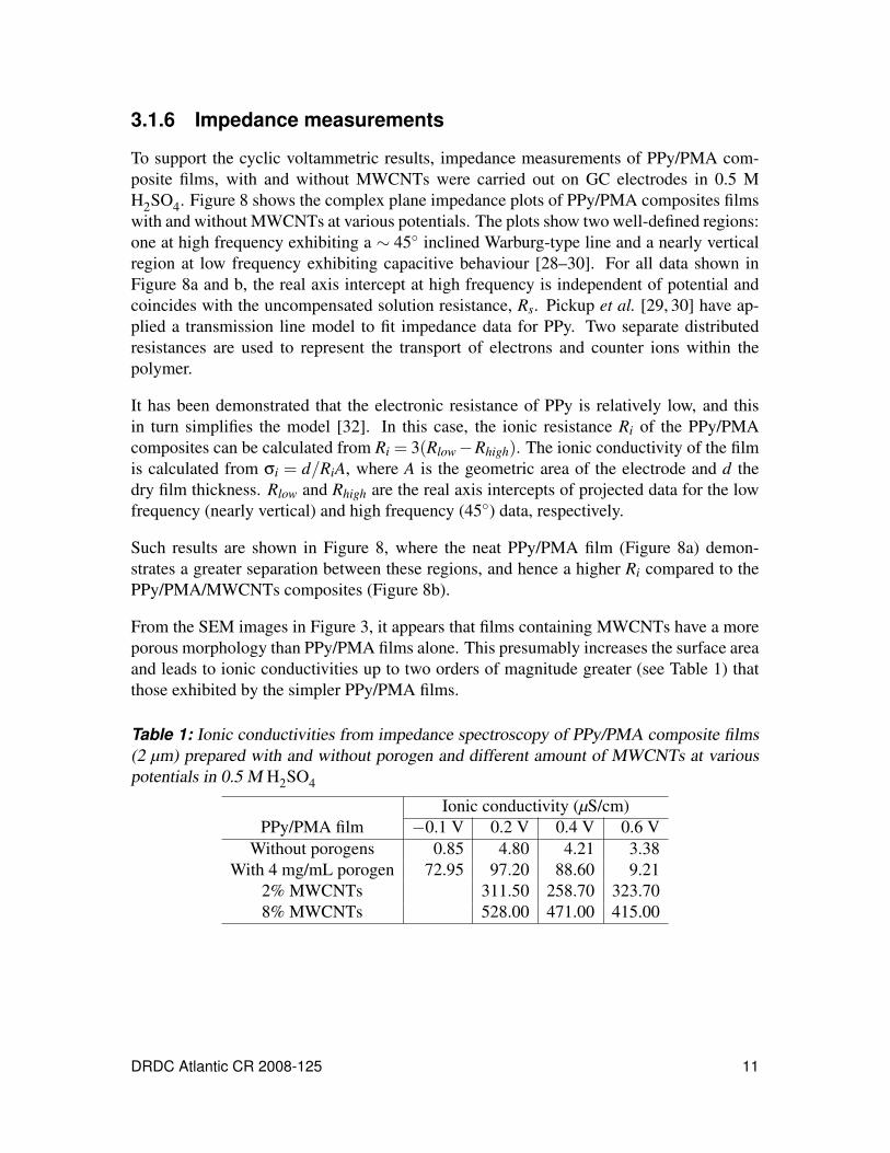
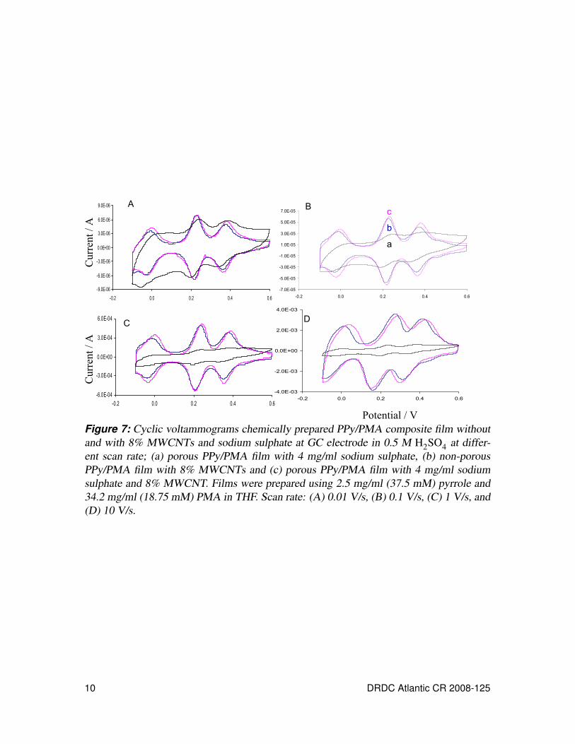
3.1.6 Impedance measurements
To support the cyclic voltammetric results, impedance measurements of PPy/PMA com-posite films, with and without MWCNTs were carried out on GC electrodes in 0.5 MH2SO4. Figure 8 shows the complex plane impedance plots of PPy/PMA composites filmswith and without MWCNTs at various potentials. The plots show two well-defined regions:one at high frequency exhibiting a ∼ 45 inclined Warburg-type line and a nearly verticalregion at low frequency exhibiting capacitive behaviour [28–30]. For all data shown inFigure 8a and b, the real axis intercept at high frequency is independent of potential andcoincides with the uncompensated solution resistance, Rs. Pickup et al. [29, 30] have ap-plied a transmission line model to fit impedance data for PPy. Two separate distributedresistances are used to represent the transport of electrons and counter ions within thepolymer.
It has been demonstrated that the electronic resistance of PPy is relatively low, and thisin turn simplifies the model [32]. In this case, the ionic resistance Ri of the PPy/PMAcomposites can be calculated from Ri = 3(Rlow−Rhigh). The ionic conductivity of the filmis calculated from σi = d/RiA, where A is the geometric area of the electrode and d thedry film thickness. Rlow and Rhigh are the real axis intercepts of projected data for the lowfrequency (nearly vertical) and high frequency (45) data, respectively.
Such results are shown in Figure 8, where the neat PPy/PMA film (Figure 8a) demon-strates a greater separation between these regions, and hence a higher Ri compared to thePPy/PMA/MWCNTs composites (Figure 8b).
From the SEM images in Figure 3, it appears that films containing MWCNTs have a moreporous morphology than PPy/PMA films alone. This presumably increases the surface areaand leads to ionic conductivities up to two orders of magnitude greater (see Table 1) thatthose exhibited by the simpler PPy/PMA films.
Table 1: Ionic conductivities from impedance spectroscopy of PPy/PMA composite films(2 µm) prepared with and without porogen and different amount of MWCNTs at variouspotentials in 0.5 M H2SO4
Ionic conductivity (µS/cm)PPy/PMA film −0.1 V 0.2 V 0.4 V 0.6 V
Without porogens 0.85 4.80 4.21 3.38With 4 mg/mL porogen 72.95 97.20 88.60 9.21
2% MWCNTs 311.50 258.70 323.708% MWCNTs 528.00 471.00 415.00
DRDC Atlantic CR 2008-125 11
Ima
gin
ary
im
peda
nce
/
Real impedance /
b
Ima
gin
ary
im
peda
nce
/
0
200
400
600
800
1000
0 200 400 600 800 1000
-0.1 V0.2 V0.4 V0.6 Vbare
0
1000
2000
3000
4000
5000
0 1000 2000 3000 4000 5000
a
0
25
50
75
100
0 10 20 30 40 50
0
1000
2000
3000
4000
5000
0 1000 2000 3000 4000 5000
Ima
gin
ary
im
peda
nce
/
Real impedance /
b
Ima
gin
ary
im
peda
nce
/
0
200
400
600
800
1000
0 200 400 600 800 1000
-0.1 V0.2 V0.4 V0.6 Vbare
0
1000
2000
3000
4000
5000
0 1000 2000 3000 4000 5000
a
0
25
50
75
100
0 10 20 30 40 50
0
1000
2000
3000
4000
5000
0 1000 2000 3000 4000 5000
Figure 8: Complex plane impedance (Nyquist) plots (100 KHz–0.1 Hz, perturbation am-plitude 5 mV) for PPy/PMA composite films (2 µm) without (a) and with (b) 8% MWCNTsat GC electrode at various potentials in 0.5 M H2SO4. Inset: Full data set. Films were pre-pared using 2.5 mg/ml pyrrole and 63.8 mg/ml PMA in THF.
12 DRDC Atlantic CR 2008-125
-0.06
-0.04
-0.02
0
0.02
0.04
0.06
-0.2 -0.1 0 0.1 0.2 0.3 0.4 0.5 0.6 0.7
Potential (V) vs Ag/AgCl
Curr
ent
(A)
Figure 9: Cyclic voltammograms of a single layer film of undiluted PPy/PMA on carbonpaper at a scan rate of 100 mV/s.
3.2 Characterization of PPy/PMA Films Coated onCarbon Paper
3.2.1 Redox behaviour
Figure 9 shows the cyclic voltammogram of a 1 cm2 (geometric area) piece of carbon papercoated once with the undiluted solution. The weight of the active material made up about7% of the weight of carbon paper (as opposed to the case of the carbon nanotubes where thenanotubes were added as a weight percent of the monomer). The peaks are well defined butdue to the high current being passed (tens of milliamps) the solution resistance (2–3 Ω) hasbeen compensated, since without compensation, the peaks would shift by around 80 mV.
Multilayer films of dilute solutions (1/3 and 1/5 dilution) were made to test and compare theproperties of multiple thin layers against a single thick layer. One possibility is that multipletreatments of a dilute solution might produce a more uniform coating on the carbon paper.Each layer was rinsed in methanol prior to a new coating, and additional layers were addeduntil the current passed at a scan rate of 100 mV/s matched that of an undiluted, singlelayer film. Figure 10 shows how the second oxidation peak current increases linearly witheach layer. This implies that each layer deposits uniformly on the carbon paper.
3.2.2 Switching speed
Previously we have coated glassy carbon with very thin, porous films that could be cycledup to 20 V/s [16]. In the present case, the films are much thicker so the switching speed ismuch lower. The single layer films show a linear increase of current with scan rate up to750 mV/s, using middle oxidation peak to make the comparison. In Figures 11b and d, the
DRDC Atlantic CR 2008-125 13
Potential (V) vs Ag/AgCl
Curr
ent
(A)
Layer
-0.06
-0.04
-0.02
0.00
0.02
0.04
0.06
-0.2 0 0.2 0.4 0.6 0.8
0
0.01
0.02
0.03
0.04
0.05
0 1 2 3 4 5
Peak c
urr
ent (A
)
AB
Figure 10: Cyclic voltammograms of a multi-layer film which shows the linear increaseof current as a 3 times dilute solution of PPy/PMA is coated onto carbon paper up to fourlayers at 100 mV/s (a). The peak current is for the second oxidation peak as a function ofdeposition layers (b).
increase in current with scan rate is plotted with theoretical lines for an adsorbed materialat an electrode surface (slope of 1) and for diffusion of ions through a thin layer (slope of0.5). Charging of the film also seems to occur above this scan rate (boxed area in Figure 11aand c). The charging is a result of the protons (counter ions) in solution not being able todiffuse into the film rapidly enough to counter the charge injected into the polymer matrixduring cycling. The multilayer films showed a linear increase in the middle oxidation peakcurrent only up to 250 mV/s. The overlap of cyclic voltammetry curves of increasing scanrate, due to the charging of the film at the end or each cycle, is more apparent than in thesingle layer films. The two peaks at 247 mV and 398 mV at 10 mV/s not as well resolvedat 500 mV/s (Figure 12b). The peak potentials, however, are only shifted by approximately40 mV for all peaks. This implies that the switching of redox states occurs at roughly thesame potential but is broadened due to the fast scan rate.
3.2.3 Morphology
Despite the electrochemical differences, the SEM images of a blank and a coated sampledo not appear significantly different, Figure 13. Note that the film present in the blank isa phenolic binder used in the fabrication of the carbon paper. There is also no apparentdifference in the SEM images of single and multi-layered films.
3.2.4 Redox stability
Single-layer films were less stable than the multi-layer films. Single layer films showeda current drop of about 20% after the first 50 cycles. These results are similar to thosereported for the vapour grown films of poly(3,4-ethylenedioxythiophene) (PEDOT) dopedwith PMA and 10-molybdo-2-vandophosphoric acid [22]. When grown electrochemicallyat a sweep rate of 100 mV/s, the PEDOT films were stable up to 1000 cycles. Multilayer
14 DRDC Atlantic CR 2008-125
-0.3
-0.2
-0.1
0
0.1
0.2
0.3
-0.2 -0.1 0 0.1 0.2 0.3 0.4 0.5 0.6 0.7
-0.3
-0.2
-0.1
0
0.1
0.2
0.3
-0.2 -0.1 0 0.1 0.2 0.3 0.4 0.5 0.6 0.7
-2.5
-2
-1.5
-1
-0.5
0
0 0.5 1 1.5 2 2.5 3 3.5
-2.5
-2
-1.5
-1
-0.5
0
0.5
0 0.5 1 1.5 2 2.5 3 3.5
A
Curr
ent (A
)
Potential (V)
B
D
Slope of 1
Slope of 0.5
Slope of 1
Slope of 0.5
Log(i)
Log(i)
Log(scan rate)
C
Figure 11: Cyclic voltammograms of single layer (a) and multilayer films (four layers ofa 1:3 dilute solution) (c) PPy/PMA on carbon paper. The boxed region in (a) and (c) showsthe charging of the films as scan rate is increased. The log-log plots of current vs. scan ratefor a single layer (b) and a multilayer film (d). Scan rate was increased from 10 mV/s to750 mV/s.
-0.015
-0.01
-0.005
0
0.005
0.01
0.015
-0.2 0 0.2 0.4 0.6
-0.3
-0.2
-0.1
0
0.1
0.2
0.3
-0.2 0 0.2 0.4 0.6
Cu
rren
t (A
)
Potential (V)
A B
Figure 12: Cyclic voltammograms at (a) 10 mV/s and (b) 500 mV/s of a multilayer filmshowing decrease in resolution of the peaks at 247 mV and 398 mV.
DRDC Atlantic CR 2008-125 15
(a) (b)
Figure 13: SEM of (a) a blank carbon paper, and (b)carbon paper coated with PPy/PMA.
PPy/PMA films also showed better stability with only a 10% loss in peak current over500 cycles. Although use of multilayers greatly increases the stability of PPy/PMA filmsdeposited on the carbon paper, the stability will need to be improved further.
3.2.5 Specific capacitance
Galvanostatic charge-discharge experiments were used to determine the specific capaci-tance of the PPy/PMA/carbon paper electrodes. These were performed in a three electrodecell with the carbon paper as the working electrode and 0.5 M H2SO4 as electrolyte. Con-stant currents densities of 1 to 10 mA/cm2 (geometric area) were used to charge and dis-charge the film between −0.1 and 0.6 V, yielding the potential profiles shown in Figure 14.The results are tabulated in Table 2. Specific capacitance was calculated as:
CS =i× td
∆V ×m(1)
Table 2: Specific capacitance values of PPy/PMA films. All data are for active material.
Current (A) CS (F/g)single layer multilayer
0.001 722.9 762.50.002 543.9 577.40.005 360.1 438.00.010 286.3 385.3
16 DRDC Atlantic CR 2008-125
-0.2
-0.1
0
0.1
0.2
0.3
0.4
0.5
0.6
0.7
0 100 200 300 400 500
Time /s
Pote
ntial /V
1 mA/cm2
2 mA/cm2
5 mA/cm2
10 mA/cm2
Figure 14: Charge–discharge curves for a single layer film on carbon paper at variouscurrent densities.
where CS is the specific capacitance, i is the constant current1 used, td is the discharge time,∆V is the potential over which the discharge occurred, and m is the mass of active material.
Initially at 1 mA/cm2, the multilayer film has a higher specific capacitance than the singlelayer film by 40 F/g (762.5 vs. 722.9 F/g). The difference increases to almost 100 F/g at aconstant current of 10 mA/cm2 and is most likely due to the degradation of the single layerfilm.
The total specific capacitance can also be determined from cyclic voltammetry by inte-grating over one cycle to obtain the charge (Q) and then dividing this by the width of thepotential window and mass of the active material. At a scan rate of 100 mV/s the singlelayered sample had a specific capacitance of 466 F/g and the multi-layered sample was437 F/g.
Slade et al. used a vapour deposition technique to grow films of PPy and poly-N-methyl-pyrrole doped with PMA [22], giving specific capacitances of 130 F/g and 57 F/g, re-spectively. Electrochemically grown PEDOT doped with PMA has a reported capacitanceof 140 F/g [23]. The same three polymers, grown by vapour deposition and doped with10-molybdo-2-vanadophosphoric acid gave capacitances of 422, 107, and 70 F/g for PPy,PMPY, and PEDOT, respectively [22, 23]. One can conclude, therefore, that PPy/PMAdeposited by our controlled grown method has a higher capacitance than its vapour-growncounterpart, and is comparable to PPy grown with 10-molybdo-2-vanadophosphoric acid.
1The current and current density are assumed to be equal in this instance since the geometric area of thediscs was around 1 cm2.
DRDC Atlantic CR 2008-125 17
3.3 Swagelok Capacitor Cell Using PPy/PMAComposite Films
3.3.1 Redox behaviour
A capacitor cell was fabricated based on literature sources [33–35]. The capacitor cellis a 2 electrode cell with no standard reference and therefore the reactions will occur atdifferent potentials. Initial experiments involved carbon paper sample cut into 1 cm2 disksand coated with one layer of 0.375 M (25 mg/mL) Pyrrole and 0.1875 M (342 mg/mL)PMA solutions in THF. A Nafion film soaked in 0.5 M H2SO4 was the separator, and a fewdrops of the acid was added to each electrode before the cell was sealed.
The first cycle produces one peak at the centre of the window (Figure 15). Subsequentcycling leads to the disappearance of the middle peak and the emergence of two peaks oneither side of the centre. Once this state has been reached the system becomes very stable,and after a further 400 cycles the current has dropped by only 6% (Figure 16).
-0.02
-0.015
-0.01
-0.005
0
0.005
0.01
0.015
0.02
-400 -300 -200 -100 0 100 200 300 400
1 Final
Potential /mV
Cu
rre
nt
/A
Figure 15: First and 100th cycle of a symmetric capacitor made of PPy/PMA coated car-bon paper and separated by a Nafion film soaked in 0.5 M H2SO4. Scan rate: 100 mV/s.
18 DRDC Atlantic CR 2008-125
-0.02
-0.015
-0.01
-0.005
0
0.005
0.01
0.015
0.02
-400 -300 -200 -100 0 100 200 300 400
Potential /mV
Cu
rre
nt
/A
Figure 16: Symmetric PPy/PMA capacitor after 400 cycles at 100 mV/s. First cycle (blackline) and 400th (red line )
3.3.2 Specific capacitance, energy, and power
Charge discharge experiments were performed using a current density of 1 mA/cm2 (Fig-ure 17). An ideal capacitor shows a linear relation between potential and time but therelation is nonlinear for these pseudocapacitors owing to the faradic processes. From thedischarge curve it is possible to calculate the specific capacitance and the energy and powerdensities of the cell.
The capacitance is calculated the same way as above for the three electrode cell (Equa-tion 1). The specific energy is obtained from the area under the curve in Figure 17:
ES =∫
iV dtm
(2)
with the∫
V dt term arising to account for the nonlinearity of the charge–discharge curve.Hence, the average specific power over the discharge period may be obtained:
PS,avr =ES
td(3)
For this system a power density of 103 W/kg and energy density of 1.9 Wh/kg (of activematerial) was measured. Specific cell capacitance was measured at 73 F/g. The contribu-tion of carbon paper to specific capacitance is only 16 mF/g. This was determined fromcharging and discharging a cell containing uncoated carbon paper. These results are frompreliminary work on the complete capacitor cell but fall within the range reported for con-ducting polymer/carbon nanotube composites [36] and for various asymmetric capacitorconfigurations having manganese oxide as a positive electrode [37].
DRDC Atlantic CR 2008-125 19
0
0.1
0.2
0.3
0.4
0.5
0.6
0 20 40 60 80 100 120 140 1
Time/s
Po
ten
tia
l /V
60
Charging Discharging
Figure 17: Charge–discharge curve for symmetric capacitor cell with PPy/PMA coatedcarbon paper electrodes. The cell was charged and discharged at a constant current of1 mA/cm2.
3.4 Extending the Potential Window withPhosphotungstic Acid
Since the energy of a capacitor is proportional to the square of its potential range, it is de-sirable to extend the operational voltage window of the device. In the current context, oneneeds an electroactive material stable at potentials below −0.1 V to be used as the negativeelectrode. Phosphotungstic acid (PTA) is another polyoxometalate that is similar in struc-ture to PMA but with electron transfer reactions occurring at more negative potentials [38].Figure 18 shows the voltammetry of a 10 mM solution of PTA in 0.5 M H2SO4.
Initial attempts to incorporate PTA into the PPy/PMA films were made by adding 0.5 molarequivalents of PTA into the PMA solution.There was no apparent change to the CV in thewindow of 0.6 to −0.1 V. When the window was extended to more negative potentials,the peaks associated with PTA (see Figure 18) were not observed. Figure 19 shows thePPy/PMA/PTA films cycled at 100 mV/s.
The fourth reduction peak at −0.2 V is most likely associated with PMA. The same peakcycle behaviour (smaller current passed on second cycle) is observed when PTA is notpresent in the film (Figure 19B). It is also not due to a reaction with some species insolution; rotating disk electrode experiments show a decrease in the peak current whilecycling even as the rotation speed of the electrode is increased.
It is possible to see PTA peaks in a conducting polymer when no PMA is present; PEDOTcan be electrochemically polymerized in the presence of PTA [39]. The polymer was grownfrom a solution of 0.1 mL EDOT and 500 mg of PTA in 10 mL of acetonitrile on a glassycarbon electrode by cycling between 0.8 and −0.8 V for 250 cycles at 500 mV/s. This
20 DRDC Atlantic CR 2008-125
-0.0002
-0.00015
-0.0001
-0.00005
0
0.00005
0.0001
-0.6 -0.4 -0.2 0 0.2 0.4 0.6 0.8
Potential /mV
Cu
rre
nt
/A
Figure 18: 10 mM PTA in 0.5 M H2SO4 cycled at 100 mV/s using a glassy carbon workingelectrode, Ag/AgCl reference electrode, and a platinum counter electrode.
-8.00E-03
-6.00E-03
-4.00E-03
-2.00E-03
0.00E+00
2.00E-03
4.00E-03
6.00E-03
-0.5 -0.3 -0.1 0.1 0.3 0.5 0.7
-8.00E-03
-6.00E-03
-4.00E-03
-2.00E-03
0.00E+00
2.00E-03
4.00E-03
6.00E-03
-0.5 -0.3 -0.1 0.1 0.3 0.5 0.7
Potential / V (Ag/AgCl) Potential / V (Ag/AgCl)
Cu
rre
nt /A
A B
-8.00E-03
-6.00E-03
-4.00E-03
-2.00E-03
0.00E+00
2.00E-03
4.00E-03
6.00E-03
-0.5 -0.3 -0.1 0.1 0.3 0.5 0.7
-8.00E-03
-6.00E-03
-4.00E-03
-2.00E-03
0.00E+00
2.00E-03
4.00E-03
6.00E-03
-0.5 -0.3 -0.1 0.1 0.3 0.5 0.7
Potential / V (Ag/AgCl) Potential / V (Ag/AgCl)
Cu
rre
nt /A
A B
Figure 19: PPy/PMA/PTA films (A) made with 375 mM pyrrole, 187.5 mM PMA, and93.75 mM PTA and PPy/PMA films; (B) made with 375 mM pyrrole and 187.5 mM PMAin THF. All films were cycled in 0.5 M H2SO4 with a glassy carbon working electrode.Black: first cycle, red: second cycle.
DRDC Atlantic CR 2008-125 21
-0.00015
-0.0001
-0.00005
0
0.00005
0.0001
0.00015
-0.8 -0.6 -0.4 -0.2 0 0.2 0.4 0.6
Potential /mV
Cu
rre
nt
/A
Figure 20: Voltammetric behaviour of PEDOT/PTA.
produced a thin blue film on the electrode. It was dried in vacuum then cycled in 0.5 MH2SO4 between 0.6 and −0.65 V at 100 mV/s (Figure 20).
It should be possible polymerize the PEDOT/PTA onto carbon paper and use it as the neg-ative electrode of a capacitor and thereby exploit its redox potential to extend the voltagerange of an asymmetric device.
4 Conclusion
Composites of PPy/PMA with carbon-containing compounds have been prepared and char-acterized in three electrode cell experiments. Films made with 8% w/w carbon nanotubesexhibited an ionic conductivity of 528 µS/cm. This is a 100-fold increase over unmodifiedPPy/PMA films.
Carbon paper is also useful as a substrate as a coating of 7% active material (PPy/PMA)gives peak currents in the tens of milliamps per square centimetre. It was shown thatmultilayer films from dilute solution are more stable than a single layer from a concentratedsolution. Preliminary work on a full capacitor cell has begun and the initial results arewithin the range of reported results for other pseudocapacitive materials.
Finally, initial experiments using phosphotungstic acid indicate that this material might bevery useful as a component of the negative electrode of an asymmetric capacitor.
22 DRDC Atlantic CR 2008-125
5 Future work
To determine the cause of the shift from one peak to two in the symmetric capacitor voltam-mogram, it may be necessary to set the potential of each disc against a reference beforeusing it in the 2-electrode capacitor cell. In such a process, it should be possible to chargeeach electrode to one-half its capacity, as opposed to having each close to its fully oxidizedstate as will be the case immediately following polymerization. In general terms, settingeach electrode to its half-charged state would maximize the overall storage capacity of thedevice, and we plan to explore this concept further.
It would be beneficial to use a material containing phosphotungstic acid as a negative elec-trode in an asymmetric capacitor since doing so can increase the potential window (andhence energy) of the device. PTA can be incorporated into films electrochemically but it isdifficult to do chemically because of its low oxidation potential.
DRDC Atlantic CR 2008-125 23
Symbols and Abbreviations
σi: Ionic conductivity
EDOT: Ethylenedioxythiophene
CNT: Carbon nanotube
CV: Cyclic voltammetry or voltammogram
GC: Glassy carbon (electrode)
ITO: Indium-doped tin oxide
MWCNT: Multiwalled carbon nanotube
PEDOT: Poly ethylenedioxythiophene
PMA: Phosphomolybdic acid
PPy: Polypyrrole
PTA: Phosphotungstic acid
SEM: Scanning electron microscope / micrograph
THF: Tetrahydrofuran
CS: Specific capacitance
ES: Specific energy
PS,avr: Average specific power density
Re: Electronic resistance
Rhigh: Extrapolated high frequency resistance
Ri: Ionic resistance
Rlow: Extrapolated low frequency resistance
Rs: Solution resistance
V : Potential
i: Current
m: Mass of active material
td: Discharge time
24 DRDC Atlantic CR 2008-125
References
[1] Zheng, J. P., Huang, J., and Jow, T. R. (1997), J. Electrochem. Soc., 144, 2026.
[2] Frackowiak, E. (2001), Carbon, 39, 937.
[3] Zheng, J. (1995), J. Electrochem. Soc., 142, L6.
[4] Khudo, T., Ikeda, Y., Watanabe, T., Hibino, M., Miyayama, M., Abe, H., and Kajita,K. (2002), Solid State Ionics, 152, 833.
[5] Novak, P., Mueller, K., Santhanam, K. S. V., and Haas, O. (1997), Chem Rev., 97,207.
[6] Oyama, N., Tatsuma, Y., Sato, T., and Sotomura, T. (1995), Nature, 373, 598.
[7] Rudge, A. D., John, R. I., Gottesfeld, S., and Ferraris, J. P. (1994), J. Power Sources,47, 89.
[8] Chen, W. C. and Wen, T. C. (2003), J. Power Sources, 117, 273.
[9] Gomez-Romero, P (2001), Adv. Mater., 13, 163.
[10] Cuentas-Gallegos, K., Lira-Cantu, M, Casan-pastor, N., and Gomez-Romero, P.(2005), Adv. Funct. Mater., 15, 1125.
[11] Vaillant, J., Lira-Cantu, M., Cuentas-Gallegos, K., Casan-pastor, N., andGomez-Romero, P. (2006), Prog. Solid State Chem., 34, 147.
[12] Freund, M. S., Karp, C., and Lewis, N. S. (1995), Inorg. Chim. Acta, 240, 447.
[13] Freund, Michael S. (2005), Controlled Chemical Polymerization Method forProcessing Conducting Polymers: First Year Progress Report, (CR 2005-080)Defence R&D Canada – Atlantic.
[14] Freund, Michael S. (2005), Controlled Chemical Polymerization Method forProcessing Conducting Polymers Part 2: Final Report, (CR 2005-130) DefenceR&D Canada – Atlantic.
[15] Freund, Michael S. (2007), Electrochemical Supercapacitors: First Annual Report,(CR 2007-199) Defence R&D Canada – Atlantic.
[16] Suppes, G.M., Deore, B.A., and Freund, M.S. (2008), Langmuir, 24, 1064.
[17] Li, Z., Chen, J., Pan, D., Tao, W., Nie, L., and Yao, S. (2006), Electrochimica Acta,51, 4255.
[18] Pan, D., Chen, J., Tao, W., Nie, L., and Yao, S. (2006), Langmuir, 22, 5872.
DRDC Atlantic CR 2008-125 25
[19] Xu, W., Liu, C., Xing, W., and Lu, T. (2007), Electrochem. Comm., 9, 180.
[20] Garrigue, P., H., Delville M., Labrugere, C., Cloutet, E., Kulesza, P. J., Morand, J. P.,and Kuhn, A. (2004), Chem. Mater., 16, 2984.
[21] Tang, Q., Luo, X., and Wen, R. (2005), Anal. Lett., 38, 1445.
[22] White, A. M. and Slade, R. C. T. (2003), Electrochimica Acta, 48, 2583.
[23] White, A. M. and Slade, R.C. T. (2004), Electrochim. Acta, 49, 861.
[24] White, A. M. and Slade, R. C. T. (2003), Synth. Met., 139, 123.
[25] Schewegler, M. A., Vinke, P., Eijk, M., and Bekkum, H. (1992), Appl. Cat. A, 80, 41.
[26] Gall, R. D., Hill, C. L., and Walker, J. E. (1996), Chem. Mater., 8, 2523.
[27] Kim, D. R., Cha, W., and Paik, W. (1997), Synth. Met., 84, 759.
[28] Albery, W. J., Elliott, C. M., and Mount, A. R. (1990), J. Electroanal. Chem., 288,15.
[29] Duffitt, G. L. and Pickup, P. G. (1992), J. Chem. Soc. Faraday. Trans., 88, 1417.
[30] Pickup, P. G. (1990), J. Chem. Soc. Faraday. Trans., 86, 3631.
[31] Ren, X. and Pickup, P. G. (1993), J. Chem. Soc. Faraday. Trans., 89, 321.
[32] Ren, P. G., X.; Pickup (1993), J. Phys. Chem., 97, 5356.
[33] Munoz-Rojas, D., Leriche, J.-B., Delacourt, C., Poizot, P., Palacin, M. R., andTarascon, J.-M. (2007), Electrochem. Comm., 9, 708.
[34] Khomenko, V., Raymundo-Pinero, E., and Beguin, F. (2006), J. Power Sources, 153,183.
[35] Gomez-Romero, Pedro, Chojaka, Malgorzata, Cuentas-Gallegosa, Karina, Asensioa,Juan A., Kuleszab, Pawel J., Casan-Pastora, Nieves, and Lira-Cantu, Monica (2003),Electrochem. Comm., 5, 149.
[36] Frackowiak, E., Khomenko, V., Jurewicz, K., Lota, K., and Beguin, F. (2006), J.Power Sources, 153, 413.
[37] Belanger, D., Brousse, T., and Long, J. W. (2008), E.C.S. Interface, spring, 49.
[38] Holmstrom, S.D., Karwowska, B., Cox, J.A., and Kulesza, P.J. (1998), J.Electroanal. Chem., 456, 239.
[39] Adamezyk, L., Kulesza, P. J., Miecznikowski, K., Palys, B., Chojak, M., andKrawczyk, D. (2005), J. Electrochem. Soc., 152, E98.
26 DRDC Atlantic CR 2008-125
Distribution list
DRDC Atlantic CR 2008-125
Internal distribution2 Colin Cameron; 1 CD, 1 paper
1 Trisha Huber
1 Ed Andrukaitis
1 Jeff Szabo, GL/MC
1 Calvin Hyatt, H/DLA
5 DRDC Atlantic Library
Total internal copies: 11
External distribution2 Prof. Michael Freund; 1 CD, 1 paper
Department of Chemistry, University of ManitobaWinnipeg, MB R3T 2N2
1 Prof. Peter G. PickupDepartment of ChemistryMemorial University of NewfoundlandSt. John’s NL A1B 3X7
1 Prof. Alex AdronovDepartment of Chemistry, McMaster University1280 Main St. WHamilton, ON L8S 4M1
1 Prof. Daniel BelangerDept. de chimie, Universite de Quebec a MontrealCP 888 Succ. Centre VilleMontreal, QC H3C 3P8
1 DRDKIM
Total external copies: 6
Total copies: 17
DRDC Atlantic CR 2008-125 27

This page intentionally left blank.
28 DRDC Atlantic CR 2008-125
DOCUMENT CONTROL DATA(Security classification of title, body of abstract and indexing annotation must be entered when document is classified)
1. ORIGINATOR (The name and address of the organization preparing thedocument. Organizations for whom the document was prepared, e.g. Centresponsoring a contractor’s report, or tasking agency, are entered in section 8.)
University of ManitobaDepartment of ChemistryWinnipeg MB R3T 2N2
2. SECURITY CLASSIFICATION (Overallsecurity classification of the documentincluding special warning terms if applicable.)
UNCLASSIFIED
3. TITLE (The complete document title as indicated on the title page. Its classification should be indicated by the appropriateabbreviation (S, C or U) in parentheses after the title.)
Electrochemical Supercapacitors: Second Annual Report
4. AUTHORS (Last name, followed by initials – ranks, titles, etc. not to be used.)
Freund, M.S.; Suppes, G.; Deore, B.
5. DATE OF PUBLICATION (Month and year of publication ofdocument.)
September 2008
6a. NO. OF PAGES (Totalcontaining information.Include Annexes,Appendices, etc.)
42
6b. NO. OF REFS (Totalcited in document.)
39
7. DESCRIPTIVE NOTES (The category of the document, e.g. technical report, technical note or memorandum. If appropriate, enterthe type of report, e.g. interim, progress, summary, annual or final. Give the inclusive dates when a specific reporting period iscovered.)
Contract Report
8. SPONSORING ACTIVITY (The name of the department project office or laboratory sponsoring the research and development –include address.)
Defence R&D Canada – AtlanticP.O. Box 1012, Dartmouth, Nova Scotia, Canada B2Y 3Z7
9a. PROJECT NO. (The applicable research and developmentproject number under which the document was written.Please specify whether project or grant.)
12sz07
9b. GRANT OR CONTRACT NO. (If appropriate, the applicablenumber under which the document was written.)
W7707-063349
10a. ORIGINATOR’S DOCUMENT NUMBER (The officialdocument number by which the document is identified by theoriginating activity. This number must be unique to thisdocument.)
DRDC Atlantic CR 2008-125
10b. OTHER DOCUMENT NO(s). (Any other numbers which maybe assigned this document either by the originator or by thesponsor.)
11. DOCUMENT AVAILABILITY (Any limitations on further dissemination of the document, other than those imposed by securityclassification.)( X ) Unlimited distribution( ) Defence departments and defence contractors; further distribution only as approved( ) Defence departments and Canadian defence contractors; further distribution only as approved( ) Government departments and agencies; further distribution only as approved( ) Defence departments; further distribution only as approved( ) Other (please specify):
12. DOCUMENT ANNOUNCEMENT (Any limitation to the bibliographic announcement of this document. This will normally correspondto the Document Availability (11). However, where further distribution (beyond the audience specified in (11)) is possible, a widerannouncement audience may be selected.)

13. ABSTRACT (A brief and factual summary of the document. It may also appear elsewhere in the body of the document itself. It is highlydesirable that the abstract of classified documents be unclassified. Each paragraph of the abstract shall begin with an indication of thesecurity classification of the information in the paragraph (unless the document itself is unclassified) represented as (S), (C), (R), or (U).It is not necessary to include here abstracts in both official languages unless the text is bilingual.)
This report summarizes results from the second year of this three year project in developingsupercapacitor electrode materials based on conducting polymers. Work has continued usingthe controlled growth polymerization method to manipulate porosity in films of polypyrrole. It wasfound that composites of polypyrrole and multiwalled carbon nanotubes had an ionic conductivitytwo orders of magnitude greater than the polypyrrole films alone. Polypyrrole films on carboncloth were also examined and found to possess enhanced stability if the polymer is built-up inlayers. Finally, preliminary results indicate that conducting polymer films containing phospho-tungstic acid may serve well as the negative electrode in an asymmetric capacitor.
14. KEYWORDS, DESCRIPTORS or IDENTIFIERS (Technically meaningful terms or short phrases that characterize a document and couldbe helpful in cataloguing the document. They should be selected so that no security classification is required. Identifiers, such asequipment model designation, trade name, military project code name, geographic location may also be included. If possible keywordsshould be selected from a published thesaurus. e.g. Thesaurus of Engineering and Scientific Terms (TEST) and that thesaurus identified.If it is not possible to select indexing terms which are Unclassified, the classification of each should be indicated as with the title.)
supercapacitor; conducting polymer; pyrrole; phosphomolybdic acid; assymetric; pseudocapac-itance

This page intentionally left blank.