Embed Size (px)
Citation preview
University of Pennsylvania
SUNFEST
NSF REU Program Summer 2007
Assembly and Testing of Poly(3,4-Propylenedioxythiophene) Based Electrochemical Supercapacitors
NSF Summer Undergraduate Fellowship in Sensor Technologies Victor Uriarte (Mechanical Engineer) - Florida International University
Advisors: Dr. Jorge Santiago-Avilés Dr. Mariem Rosario-Canales
Abstract
Neither traditional capacitors nor batteries are capable of releasing high amounts of energy at high power. Supercapacitors represent a middle ground because they can hold and release
considerable amounts of energy while doing so at a medium power. Continuous research in the supercapacitor area has been geared towards the testing of various active materials like metal
oxides and electroactive polymers to probe their properties in this field. This paper presents the initial results for tests done with the electroactive polymer poly(3,4-propylenedioxythiophene) in
an electrolyte system composed of the salt tetraethylammonium bis(trifluoromethylsulfonyl)imide, the ionic liquid 1-ethyl-3-methylimidazolium
bis(trifluoromethylsulfonyl)imide, and propylene carbonate as solvent.
2
TABLE OF CONTENTS 1. INTRODUCTION ............................................................................................................3
2. BACKGROUND ..............................................................................................................3
2.1 Capacitors: Classes and Equations for Basic Geometry ............................................3 2.2 Double Layer and Electrochemical Capacitors...........................................................4 2.3 Components of Electrochemical Capacitors...............................................................5
3. EXPERIMENTAL SETUP...............................................................................................6 3.1 Electropolymerization of ProDOT Monomer and Morphology Evaluation...............6 3.2 Evaluation of PProDOT Films....................................................................................7 3.3 Device Assembly and Testing ....................................................................................7
4. RESULTS AND DISCUSSION.......................................................................................9
4.1 Electropolymerization of ProDOT in Both Electrolyte Systems................................9 4.1.1 Evaluation of Polymer Films ........................................................................11
4.2 Device Assembly and Testing ..................................................................................14 4.2.1 Oxidized and Neutral States of PProDOT ....................................................14 4.2.2 Device Scan Rate Test ..................................................................................16
5. CONTINUING WORK ..................................................................................................21
6. ACKNOWLEDGMENTS ..............................................................................................21 7. REFERENCES ...............................................................................................................21
3
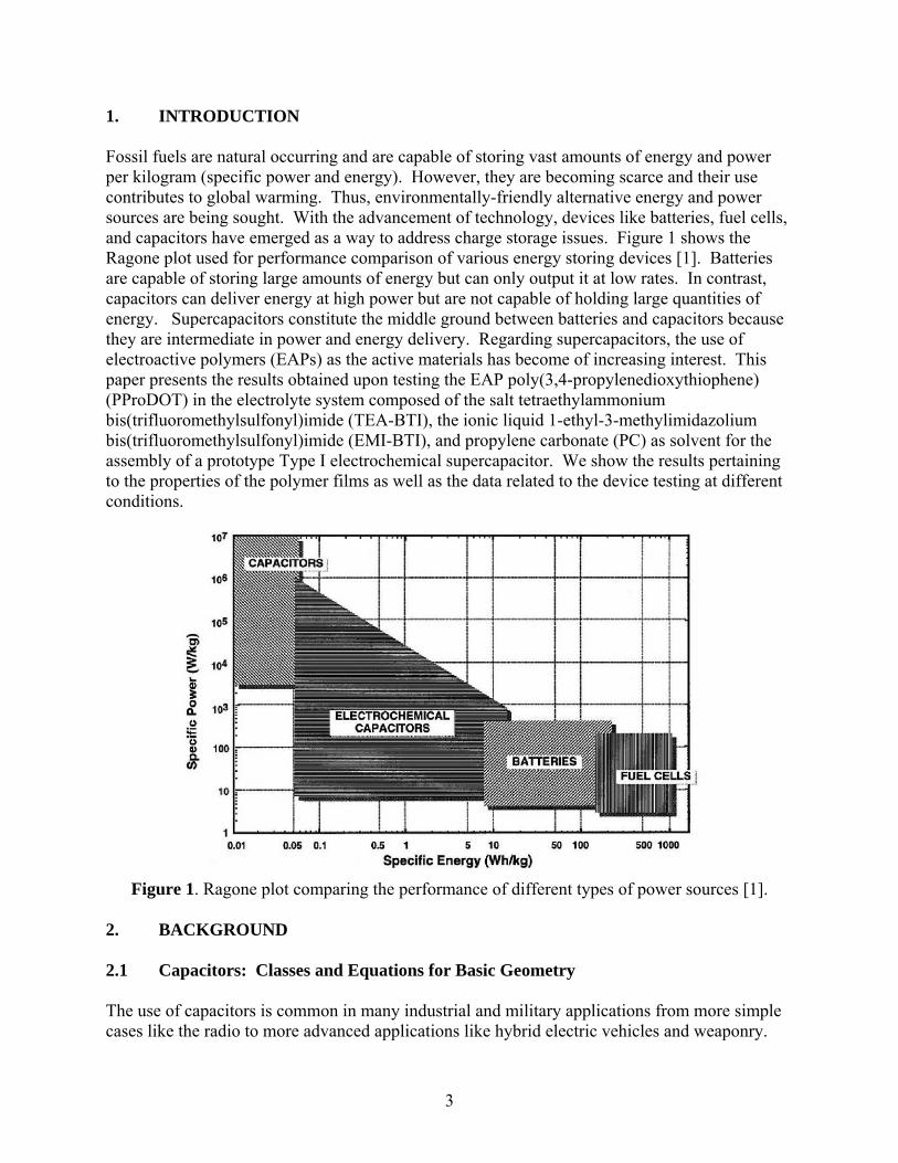
1. INTRODUCTION Fossil fuels are natural occurring and are capable of storing vast amounts of energy and power per kilogram (specific power and energy). However, they are becoming scarce and their use contributes to global warming. Thus, environmentally-friendly alternative energy and power sources are being sought. With the advancement of technology, devices like batteries, fuel cells, and capacitors have emerged as a way to address charge storage issues. Figure 1 shows the Ragone plot used for performance comparison of various energy storing devices [1]. Batteries are capable of storing large amounts of energy but can only output it at low rates. In contrast, capacitors can deliver energy at high power but are not capable of holding large quantities of energy. Supercapacitors constitute the middle ground between batteries and capacitors because they are intermediate in power and energy delivery. Regarding supercapacitors, the use of electroactive polymers (EAPs) as the active materials has become of increasing interest. This paper presents the results obtained upon testing the EAP poly(3,4-propylenedioxythiophene) (PProDOT) in the electrolyte system composed of the salt tetraethylammonium bis(trifluoromethylsulfonyl)imide (TEA-BTI), the ionic liquid 1-ethyl-3-methylimidazolium bis(trifluoromethylsulfonyl)imide (EMI-BTI), and propylene carbonate (PC) as solvent for the assembly of a prototype Type I electrochemical supercapacitor. We show the results pertaining to the properties of the polymer films as well as the data related to the device testing at different conditions.
Figure 1. Ragone plot comparing the performance of different types of power sources [1].
2. BACKGROUND 2.1 Capacitors: Classes and Equations for Basic Geometry
The use of capacitors is common in many industrial and military applications from more simple cases like the radio to more advanced applications like hybrid electric vehicles and weaponry.

4
There are four general classes of capacitors: 1) simple dielectric capacitors built from two conducting parallel plates or films separated by an insulating layer, 2) electrolytic capacitors where one of the electrodes is a metal plate covered by an insulating oxide layer and the second electrode is a liquid or solid electrolyte, 3) double-layer capacitors comprised of two carbonaceous electrodes and also categorized as ultracapacitors, and 4) redox or electrochemical capacitors, also known as supercapacitors, where the use of metal oxides or EAPs is typically involved [2,3]. The simple dielectric capacitors follow a standard circuit model and the capacitance (C) is given by equation 1 [2]:
dAC ⋅
=ε
(1)
where ε is the electrical permittivity of the insulating layer, A is the surface area of the plates, and d is the plate spacing. Applying a potential difference (V) between the plates leads to the storage of charge (Q) represented by equation 2 [2]:
VCQ ⋅= (2)
As capacitors are used in electrical circuits, the equations for equivalent capacitance (Cequiv) when connected in parallel and in series are [2]:
Parallel nnequiv CCCCC ++++= −121 ... (3)
Series nnequiv CCCCC
11...111
121
++++=−
(4)
Regardless of its type, a real capacitor has interconnections (wires) and plates and therefore resistance and inductance. Even electrochemical capacitors possess a residual electrostatic capacitance and there will be a leakage resistance. These properties can be minimized but not avoided altogether. 2.2 Double Layer and Electrochemical Capacitors When describing capacitors, the terminology becomes complex because the existent nomenclature is often used interchangeably among types. Double layer capacitor, electrochemical capacitor, redox capacitor, supercapacitor, and ultracapacitor are all used to describe a variety of charge storage devices which differ from the traditional electrolytic and electrostatic capacitors previously mentioned. In double layer capacitors, the principle of energy storage is based on the separation of charged species in the double layer between the aqueous or organic electrolyte and an electron conductor, typically a carbonaceous material [4]. In redox or electrochemical capacitors, chemical storage of charge occurs via redox processes in the active materials typically consisting of EAPs and metal oxides like RuO2 [5]. With metal oxides the capacity is surface-area limited because the charge storage mechanism involves only the surfaces
5
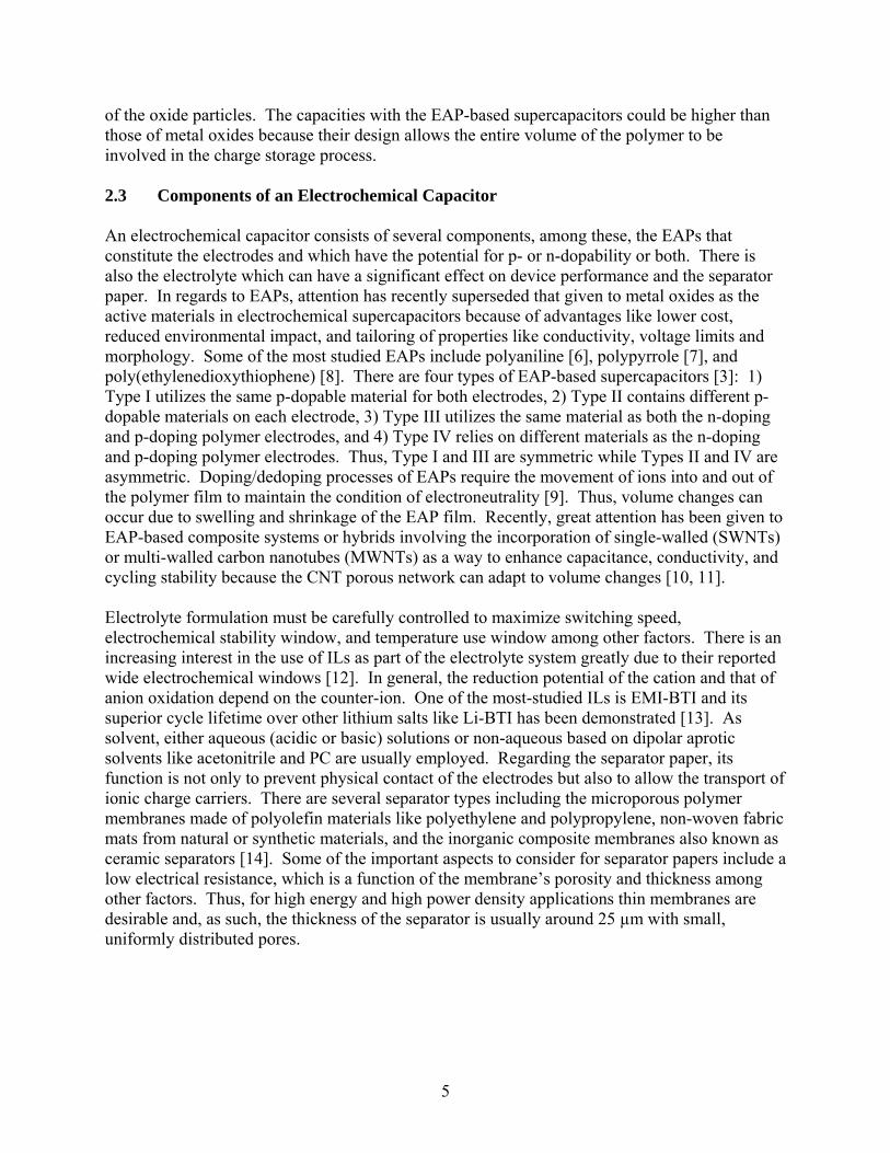
of the oxide particles. The capacities with the EAP-based supercapacitors could be higher than those of metal oxides because their design allows the entire volume of the polymer to be involved in the charge storage process. 2.3 Components of an Electrochemical Capacitor An electrochemical capacitor consists of several components, among these, the EAPs that constitute the electrodes and which have the potential for p- or n-dopability or both. There is also the electrolyte which can have a significant effect on device performance and the separator paper. In regards to EAPs, attention has recently superseded that given to metal oxides as the active materials in electrochemical supercapacitors because of advantages like lower cost, reduced environmental impact, and tailoring of properties like conductivity, voltage limits and morphology. Some of the most studied EAPs include polyaniline [6], polypyrrole [7], and poly(ethylenedioxythiophene) [8]. There are four types of EAP-based supercapacitors [3]: 1) Type I utilizes the same p-dopable material for both electrodes, 2) Type II contains different p-dopable materials on each electrode, 3) Type III utilizes the same material as both the n-doping and p-doping polymer electrodes, and 4) Type IV relies on different materials as the n-doping and p-doping polymer electrodes. Thus, Type I and III are symmetric while Types II and IV are asymmetric. Doping/dedoping processes of EAPs require the movement of ions into and out of the polymer film to maintain the condition of electroneutrality [9]. Thus, volume changes can occur due to swelling and shrinkage of the EAP film. Recently, great attention has been given to EAP-based composite systems or hybrids involving the incorporation of single-walled (SWNTs) or multi-walled carbon nanotubes (MWNTs) as a way to enhance capacitance, conductivity, and cycling stability because the CNT porous network can adapt to volume changes [10, 11]. Electrolyte formulation must be carefully controlled to maximize switching speed, electrochemical stability window, and temperature use window among other factors. There is an increasing interest in the use of ILs as part of the electrolyte system greatly due to their reported wide electrochemical windows [12]. In general, the reduction potential of the cation and that of anion oxidation depend on the counter-ion. One of the most-studied ILs is EMI-BTI and its superior cycle lifetime over other lithium salts like Li-BTI has been demonstrated [13]. As solvent, either aqueous (acidic or basic) solutions or non-aqueous based on dipolar aprotic solvents like acetonitrile and PC are usually employed. Regarding the separator paper, its function is not only to prevent physical contact of the electrodes but also to allow the transport of ionic charge carriers. There are several separator types including the microporous polymer membranes made of polyolefin materials like polyethylene and polypropylene, non-woven fabric mats from natural or synthetic materials, and the inorganic composite membranes also known as ceramic separators [14]. Some of the important aspects to consider for separator papers include a low electrical resistance, which is a function of the membrane’s porosity and thickness among other factors. Thus, for high energy and high power density applications thin membranes are desirable and, as such, the thickness of the separator is usually around 25 µm with small, uniformly distributed pores.
6
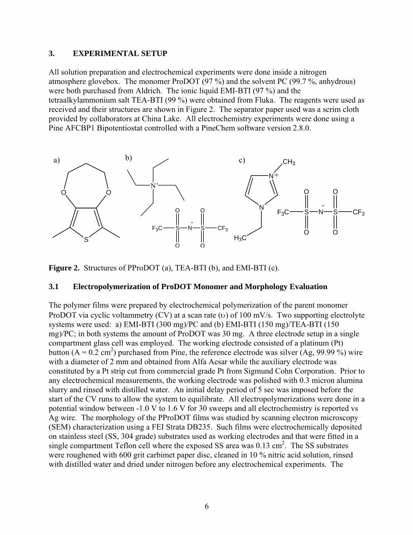
3. EXPERIMENTAL SETUP All solution preparation and electrochemical experiments were done inside a nitrogen atmosphere glovebox. The monomer ProDOT (97 %) and the solvent PC (99.7 %, anhydrous) were both purchased from Aldrich. The ionic liquid EMI-BTI (97 %) and the tetraalkylammonium salt TEA-BTI (99 %) were obtained from Fluka. The reagents were used as received and their structures are shown in Figure 2. The separator paper used was a scrim cloth provided by collaborators at China Lake. All electrochemistry experiments were done using a Pine AFCBP1 Bipotentiostat controlled with a PineChem software version 2.8.0.
Figure 2. Structures of PProDOT (a), TEA-BTI (b), and EMI-BTI (c). 3.1 Electropolymerization of ProDOT Monomer and Morphology Evaluation The polymer films were prepared by electrochemical polymerization of the parent monomer ProDOT via cyclic voltammetry (CV) at a scan rate (υ) of 100 mV/s. Two supporting electrolyte systems were used: a) EMI-BTI (300 mg)/PC and (b) EMI-BTI (150 mg)/TEA-BTI (150 mg)/PC; in both systems the amount of ProDOT was 30 mg. A three electrode setup in a single compartment glass cell was employed. The working electrode consisted of a platinum (Pt) button (A = 0.2 cm2) purchased from Pine, the reference electrode was silver (Ag, 99.99 %) wire with a diameter of 2 mm and obtained from Alfa Aesar while the auxiliary electrode was constituted by a Pt strip cut from commercial grade Pt from Sigmund Cohn Corporation. Prior to any electrochemical measurements, the working electrode was polished with 0.3 micron alumina slurry and rinsed with distilled water. An initial delay period of 5 sec was imposed before the start of the CV runs to allow the system to equilibrate. All electropolymerizations were done in a potential window between -1.0 V to 1.6 V for 30 sweeps and all electrochemistry is reported vs Ag wire. The morphology of the PProDOT films was studied by scanning electron microscopy (SEM) characterization using a FEI Strata DB235. Such films were electrochemically deposited on stainless steel (SS, 304 grade) substrates used as working electrodes and that were fitted in a single compartment Teflon cell where the exposed SS area was 0.13 cm2. The SS substrates were roughened with 600 grit carbimet paper disc, cleaned in 10 % nitric acid solution, rinsed with distilled water and dried under nitrogen before any electrochemical experiments. The
a) b) c)
OO
S
N
N
CH3
H3C
+
N S
O
O
CF3S
O
O
F3C-
N S
O
O
CF3S
O
O
F3C-
N+
7
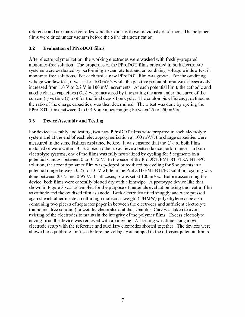
reference and auxiliary electrodes were the same as those previously described. The polymer films were dried under vacuum before the SEM characterization. 3.2 Evaluation of PProDOT films After electropolymerization, the working electrodes were washed with freshly-prepared monomer-free solution. The properties of the PProDOT films prepared in both electrolyte systems were evaluated by performing a scan rate test and an oxidizing voltage window test in monomer-free solutions. For each test, a new PProDOT film was grown. For the oxidizing voltage window test, υ was set at 100 mV/s while the positive potential limit was successively increased from 1.0 V to 2.2 V in 100 mV increments. At each potential limit, the cathodic and anodic charge capacities (C1/2) were measured by integrating the area under the curve of the current (I) vs time (t) plot for the final deposition cycle. The coulombic efficiency, defined as the ratio of the charge capacities, was then determined. The υ test was done by cycling the PProDOT films between 0 to 0.9 V at values ranging between 25 to 250 mV/s. 3.3 Device Assembly and Testing For device assembly and testing, two new PProDOT films were prepared in each electrolyte system and at the end of each electropolymerization at 100 mV/s, the charge capacities were measured in the same fashion explained before. It was ensured that the C1/2 of both films matched or were within 30 % of each other to achieve a better device performance. In both electrolyte systems, one of the films was fully neutralized by cycling for 5 segments in a potential window between 0 to -0.75 V. In the case of the ProDOT/EMI-BTI/TEA-BTI/PC solution, the second polymer film was p-doped or oxidized by cycling for 5 segments in a potential range between 0.25 to 1.0 V while in the ProDOT/EMI-BTI/PC solution, cycling was done between 0.375 and 0.95 V. In all cases, υ was set at 100 mV/s. Before assembling the device, both films were carefully blotted dry with a kimwipe. A prototype device like that shown in Figure 3 was assembled for the purpose of materials evaluation using the neutral film as cathode and the oxidized film as anode. Both electrodes fitted snuggly and were pressed against each other inside an ultra high molecular weight (UHMW) polyethylene cube also containing two pieces of separator paper in between the electrodes and sufficient electrolyte (monomer-free solution) to wet the electrodes and the separator. Care was taken to avoid twisting of the electrodes to maintain the integrity of the polymer films. Excess electrolyte oozing from the device was removed with a kimwipe. All testing was done using a two-electrode setup with the reference and auxiliary electrodes shorted together. The devices were allowed to equilibrate for 5 sec before the voltage was ramped to the different potential limits.
8
Figure 3. Prototype setup for a supercapacitor device.
Following device assembly, a scan rate test was done in a potential window between 0 to 0.5 V. Initially ν was set at 250 mV/s followed by testing at slower ν of 100, 50, and 25 mV/s; testing continued by cycling at faster ν between 350 and 10000 mV/s. At each υ, the cathodic and anodic C1/2 were measured to analyze the υ-dependence of the charge capacity and the depth of discharge (DOD) was calculated. A voltage limit test of the devices followed starting with an initial potential limit of 0.5 V over 1,000 and 20,000 cycles and testing continued by successively incrementing the potential up to the point where significant changes in the peak currents, C1/2 or the appearance of irreversible peaks were observed meaning device failure. The data evaluated from these tests included the following:
2d
avgV
V = (5)
where Vavg is the average voltage in Volts and Vd is the device voltage also in Volts,
avgavg VCE ⋅= 2/1 (6) where Eavg is the average energy delivered by the device in Joules,
tC
I avg Δ= 2/1
(7)
Separator Paper
UHMW Polyethylene
cube
Cathode
Anode
9
where Iavg is the average current in Amperes and Δt is the time span of the experiment in sec
dVCC 2/1= (8)
where C is the capacitance in Farads. Alternatively, C can be obtained by normalizing the average current relative to the scan rate. Thus,
νavgI
C = (9)
The average power (Pavg) in units of Joules/sec or Watts can be calculated from the relation
avgavgavg IVP ⋅= (10) By normalizing both Eavg and Pavg relative to the area (A) of the device, one can report
AE
E avgnorm = (11)
AP
P avgnorm = (12)
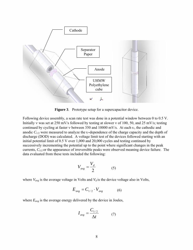
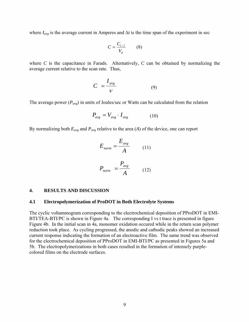
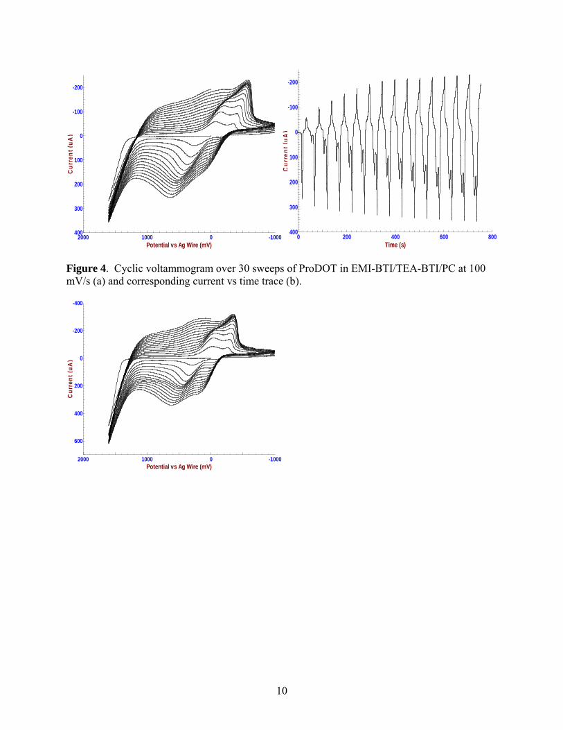
4. RESULTS AND DISCUSSION 4.1 Electropolymerization of ProDOT in Both Electrolyte Systems The cyclic voltammogram corresponding to the electrochemical deposition of PProDOT in EMI-BTI/TEA-BTI/PC is shown in Figure 4a. The corresponding I vs t trace is presented in figure Figure 4b. In the initial scan in 4a, monomer oxidation occured while in the return scan polymer reduction took place. As cycling progressed, the anodic and cathodic peaks showed an increased current response indicating the formation of an electroactive film. The same trend was observed for the electrochemical deposition of PProDOT in EMI-BTI/PC as presented in Figures 5a and 5b. The electropolymerizations in both cases resulted in the formation of intensely purple-colored films on the electrode surfaces.
10
-1000010002000Potential vs Ag Wire (mV)
-200
-100
0
100
200
300
400
Cur
rent
(uA
)
0 200 400 600 800Time (s)
-200
-100
0
100
200
300
400
Cur
rent
(uA
)
Figure 4. Cyclic voltammogram over 30 sweeps of ProDOT in EMI-BTI/TEA-BTI/PC at 100 mV/s (a) and corresponding current vs time trace (b).
-1000010002000Potential vs Ag Wire (mV)
-400
-200
0
200
400
600
Cur
rent
(uA
)