Embed Size (px)
Citation preview
ELECTROCHEMICAL STUDIES ON
METAL PHTHALOCYANINES
Thesis submitted to
the Cochin University of Science and Technology
in partial fulfilment of the requirements
for the degree of
DOCTOR OF PHILOSOPHY
by
HARIKUMAR P. S.
DEPARTMENT OF APPLIED CHEMISTRY
COCHIN UNIVERSITY OF SCIENCE AND TECHNOLOGY
COCHIN - 682022
JANUARY 1990
DECLARATION
I hereby declare that the work presented in this thesis is based on the original work done by me under the guidance of Dr. V.N. Sivasankara Pillai, Professor, Deparunent of Applied Chemistry, Cochin University of Science and Technology and that no part of this thesis has been included in any other thesis submitted previously for the award of any degree.
Cochin - 22 17111 January 1990
CERTIFICATE
Certified that the work presented in this thesis is based on the bonafide work done by Mr. Harimumar, P.S. under my guidance in the Department of Applied Chemistry, Cochin University of Science and Technology and that no part themf has been included in any other thesis submitted previously for the award of any degree.
Cochin - 22, 17th January 1990
DR. V.N. SIV ASANKARA PILLAI Professor
Department of Applied Chemistry Cochin University of Science and Technology
ACKNOWLEDGEMENT
I wish to express my sincere gratitude and obligation to Prof. V.N. Si vasankara Pillai, for his kind and patient guidance and encouragement given all through the period of my research.
The help extended by Prof. Paul A. Vatakencherry, Head of the Department of Applied Chemistry is gratefully acknowledged. I am extremely thankful to all the faculty members of this department for their co-operation and encouragement
I am very much indebted to Dr. Syed Akheel Ahamed, Department of P.G. Studies and Research in Chemistry, University of Mysore and Dr.K. Ravindran, Head, Crafts and Gears Division, CIFf, Cochin for their valuable suggestions.
I am thankful to the administrative and technical staff of the Department of Applied Chemistry and the staff of the University Science Instrumentation Centre for their timely help and co-operation.
The endless support. affection and timely help extended by my friends are remembered with great appreciation and a deep sense of gratitude.
The financial assistance extended to me in the fonn of Research Fellowship. by the university Grants Commission. Government of India is gratefully acknowledged.
Finally I would like to extend my gratitude to Mrs. Bharathi, P.A. and Mls. TC Computeck Pte Ltd. South Kalamassery for their excellent work at typing this thesis.
HARIKUMAR p.s
PREFACE
The work embodied in this thesis was carried out by the author in the Department of Applied Chemistry dwing 1985 -'89. The primary aim of these investigations was to probe the elecnuchemical and material science aspects of some selected metal phthalocyanines(MPcs).
Metal phthalocyanines are characterised by a unique planar molecular structure. As a single class of compounds they have been the subject of ever increasing number of physicochemical and technological investigations. During the last two decades the literature on these compounds was flooded by an outpour of original publications and patents. Almost every branch of materials science has benefited by their application-swface coating, printing, electrophotography, photoelectrochemistry, electronics and medicine to name a few.
The present study was confined to the electrical and electrochemical properties of cobalt, nickel, zinc. iron and copper phthalocyanines. The use of soluble Pes as corrosion inhibitor for aluminium was also investigated.
In the introductory section of the thesis, the work done so far on MPcs is reviewed. In this review emphasis is given to their general methods of synthesis and the physicochemical properties.
In phthalocyanine chemistry one of the formidable tasks is the isolation of singular species. In the second chapter the methods of synthesis and purification are presented with necessary experimental details.
The studies on plasma modified films of CoPe, FePc, ZnPc. NiPc and CuPc are presented in the third chapter. Modification of electron transfer process by such films for reversible redox systems is taken as the criterion to establish enhanced electrocatalytic activity.
Metal phthalocyanines are p- type semiconductors and the conductivity is enhanced by doping with iodine. The effect of doping on the activation energy of the conduction process is evaluated by measuring the temperature dependent variation of conductivity. Effect of thennal treatment on iodine doped CoPc is investigated by DSC,magnetic susceptibility, IR, ESR and electronic spectra. The elecnucatalytic activity of such doped materials was probed by cyclic voltammetry. The results are presented in the fourth chapter.
The electron transfer mediation characteristics of MPc films depend on the film thickness. The influence of reducing the effective thickness of the MPc film by dispersing it into a conductive polymeric matrix was investigated. Tetrasulphonated cobalt phthalocyanine (CoTSP) was electrostatically immobilised into polyaniline and poly(o-toluidine) under varied conditions. Such chemically modified electrodes were studied and the results are presented in the fifth chapter.
Chapter six contains the studies on corrosion inhibition of aluminium by CoTSP and CuTSP. By virtue of their anionic character they are soluble in water and are strongly adsorbed on aluminium. Hence they can act as corrosion inhibitors. CoTSP is also known to catalyze the reduction of dioxygen.This reaction can accelerate the anodic dissolution of metal as a complementary reaction. The influence of these conflicting properties of CoTSP on the corrosion of aluminium was studied and compared with those of CuTSP.
In the concluding chapter the salient features of the results obtained are summarised.

In the course of these investigations a number of gadgets like cell for measuring the electrical conductivity of solids under non-isothermal conditions, low power rf oscillator and a rotating disc electrode were fabricated. These are mentioned in appropriate sections.
CONTENTS
CHAPTER 1. A BRIEF SURVEY OF THE WORK ON METAL PHTHALOCYANINES
1.1 1.2
1.2.1 1.2.2 1.2.3
1.3 1.4
1.4.1 1.4.2 1.4.3 1.4.4 1.4.5
1.5
Structure of Phthalocyanine General Methods for the Synthesis of Phthalocyanines Monomeric Phthalocyanine Lanthanide and Actinide Phthalocyanines Miscellaneous MPcs Purification of Metal Phthalocyanines Physicochemical Characteristics of Metal Phthalocyanines Crystal Structure and Polymorphism Spectral Characteristics Magnetic Propertis Electrical Characteristics of MPcs Aggregation of MPcs Technological Application of Phthalocyanines
CHAPTER n SYNTHESIS AND CHARACTERISATION OF METAL PHTHALOCYANINES
2.1 2.1.2
Synthesis of Metal Phthalocyanines Characterisation of Metal Phthalocyanines
CHAYfERm ELECTROCHEMICAL STUDIES
3.1 3.1.1 3.1.3 3.1.5
3.2 3.3
Introduction Plasma Treatment of MPc Layers Experimental Techniques for Plasma Treatment Application of Plasma Cyclic Voltammetry in the Study of Electrode Process Experimental Procedure
CHAYfER IV ELECTRICAL CONDUCTIVITY OF METALPHTHALOCYANINES
4.1 4.2
4.2.2 4.2.3 4.2.4
4.3 4.3.6
4.4 4.5
Introduction Experimental Characterisation of MPcI Measurment of Conductivity Cyclic Voltammetry Results and Discussion Electrochemical Studies on CoPcI Iron Phthalocyanine Zinc Phthalocyanine
PAGE NO.
1 2 2 8 8 10 10 10 12 12 13 13 14
18 19
24 25 26 27 28 31
41 42 42 42 43 43 44 45 45
CHAPTER V CHEMICALLY MODIFIED ELECTRODES PAGE NO.
5.1 5.3
5.3.1 5.3.2
5.4 5.5 5.6
5.7 5.8 5.9
5.10 5.11
5.12
Introduction Electrochemical Behaviour of Cobalt Tetrasulphophthalocyanine ion Doped into Poly aniline and poly(o-Toluidine) Introduction Experimental Preparation and Characterisation of Polyaniline Films Results and Discussion Electrochemical Characterisation of Chemically Prepared Polyaniline Electrochemical Preparation of CoTSP - PA electrodes Electrochemical Behaviour ofCoTSP - PA electrodes Dioxygen Reduction Conclusions Mediation of Electron Transfer by CoTSP Incorporated into Poly (0-Toluidine) Experimental
CHAPTER VI METAL TETRASULPHOPHTHALOCY ANINE AS CORROSION INHmITORS
6.1 6.2
6.2.2 6.3.3
Introduction Inhibition of Corrosion of Aluminium in Hydrochloric Acid by Metal Tetrasulphophthalocyanines Experimental Results and Discussion
CHAPTER VU SUMMARY AND CONCLUSION
REFERENCES
46
50 50 51 51 52
53 53 54 55 56
56 56
60
64 65 66
69
72
A BRIEF SURVEY OF THE \\-fORK O~ METAL IJHTHALULYA~Il'.t..~
1.0 INTRODUCTION
1.1 Structure of Phthalocyanines
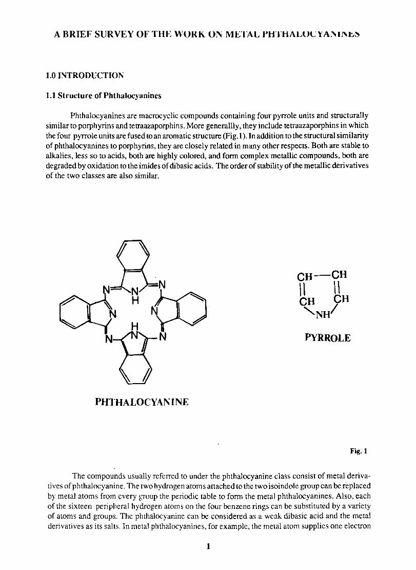
Phthalocyanines are macrocyclic compounds containing four pyrrole units and structurally similar to porphyrins and tetraazaporphins. More generallly, they include tetraazaporphins in which the four pyrrole units are fused to an aromatic structure (Fig. 1 ). In addition to the structural similarity of phthalocyanines to porphyrins, they are closely related in many other respects. Both are stable to alkalies, less so to acids, both are highly colored, and form complex metallic compounds, both are degraded by oxidation to the imides of di basic acids. The order of stabili ty of the metallic deri vati ves of the two classes are also similar.
PHTHALOCYAN INE
CH-CH , , \ \ CH CH 'NH/
PYRROLE
Fig.l
The compounds usually referred to under the phthalocyanine class consist of metal derivatives of phthalocyanine. The two hydrogen atoms attached to the two isoindole group can be replaced by metal atoms from every group the periodic table to form the metal phthalocyanines. Also, each of the sixteen peripheral hydrogen atoms on the four benzene rings can be substituted by a variety of atoms and groups. The phthalocyanine can be considered as a weak dibasic acid and the metal derivatives as its salts. In metal phthalocyanines, for example, the metal atom supplies one electron
1
each to the nitrogen atoms of the isoindole groups and these isoindole nitrogen atoms in turn supplies an electron to the metal atom, forming a covalent bond. The un shared pairs of electrons in the remaining two isoindole nitrogen atoms presumably form coordinate covalent bonds with the metal ::,' A metal phthalocyanine molecule, ~ntains four six membered chelate rings of the
-~~C-The unusual stability of these me~ co~exes can be explained by the coordination of the
central metal atom.
1.2.0 General Methods for the Synthesis of Phthalocyanines
The technological importance of phthalocyanine pigments has generated renewed interest in their synthesis, purification and characterization. The methods available for the synthesis of phthalocyanines can be classified into four groups:
1) Reaction of phthalonitrile with a metal or metal salt in a high boiling liquid like nitrobenzene or quinoline.
2) Reaction of phthalic acid or phthalic anhydride with urea and metal salts in presence of a catalyst or phthalimide with a metal salt in presence of catalyst.
3) Reaction of o-cyanobenzamide with a metal
and
4) Reaction of phthalocyanine or labile metal phthalocyanine with a metal forming a more stable phthalocyanine.
1.2.1 Monomeric phthalocyanines
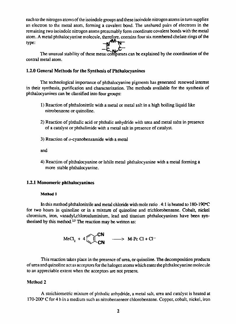
Metbod 1
In this method phthalonitrile and metal chloride with mole ratio. 4: 1 is heated to 18()"19O"C for two hours in quinoline or in a mixture of quinoline and trichlorobenzene. Cobalt, nickel chromium, iron, vanadyl,chloroaluminium, lead and titanium phthalocyanines have been synthesised by this method.2
,3 The reaction may be written as:
OCN MeD + 4 I
"2 ~ eN --> M-Pc Cl + Cl-
This reaction takes place in the presence of urea, or quinoline. The decomposition products of urea and quinoline act as acceptors for the halogen atoms which enter the phthalocyanine molecule to an appreciable extent when the acceptors are not present
Method 2
A stoichiometric mixture of phthalic anhydride, a metal salt, urea and catalyst is heated at 170-200" C for 4 h in a medium such as nitrobenzeneor chlorobenzene. Copper, cobalt, nickel, iron
2
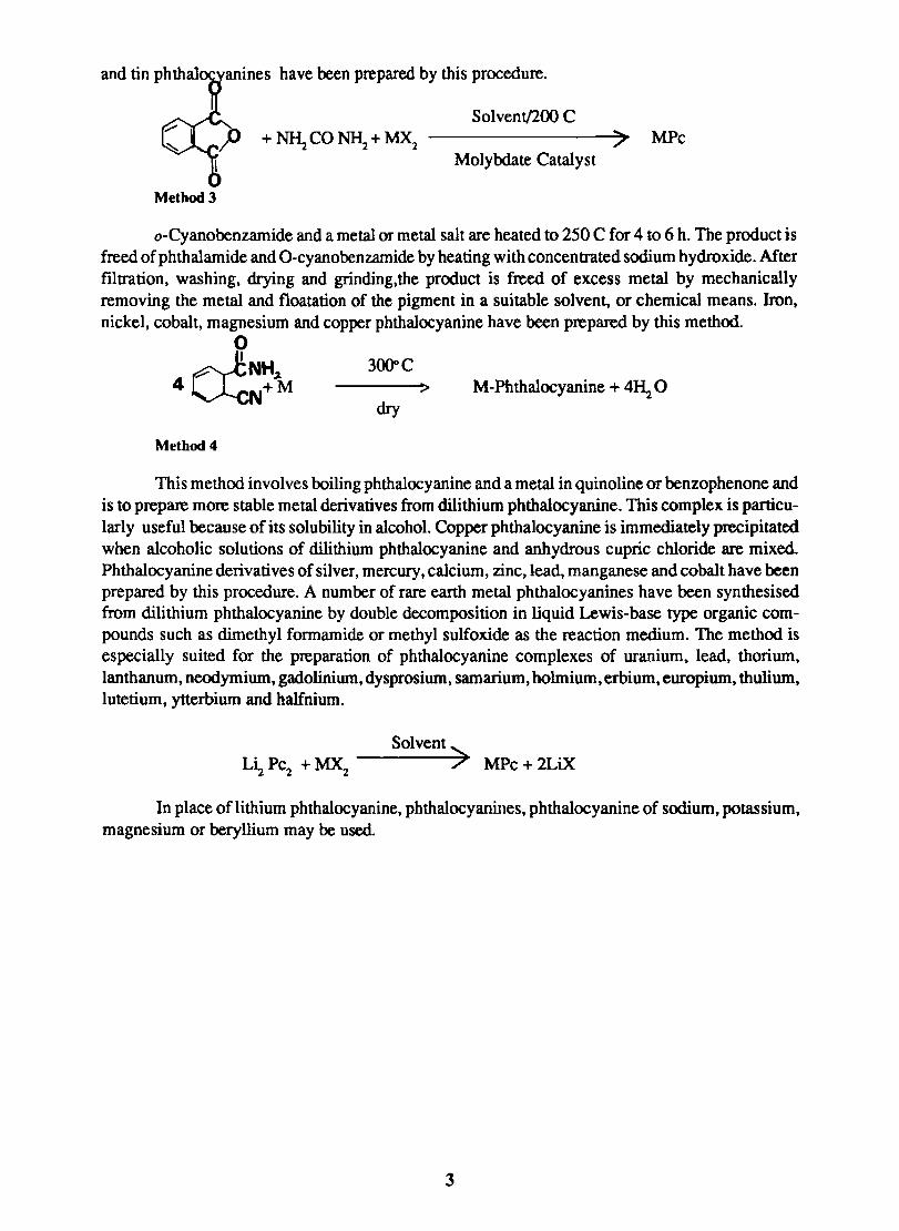
anines have been prepared by this procedure.
Solvent/200 C
+~CONl\+~ ---------------->~ MPc Molybdate Catalyst
Method 3
o-Cyanobenzamide and a metal or metal salt are heated to 250 C for 4 to 6 h. The product is freed of phthalamide and O-cyanobenzamide by heating with concen trated sodi urn hydroxide. Mter filtration, washing, drying and grinding,the product is freed of excess metal by mechanically removing the metal and floatation of the pigment in a suitable solvent, or chemical means. Iron, nickel, cobalt, magnesium and copper phthalocyanine have been prepared by this method.
o ~NH.1 4~N+M
Method 4
300"C > M-Phthalocyanine + 4~ 0
dry
This method involves boiling phthalocyanine and a metal in quinoline or benzophenone and is to prepare more stable metal derivatives from dilithium phthalocyanine. This complex is particularly useful because of its solubility in alcohol. Copper phthalocyanine is immediately precipitated when alcoholic solutions of dilithium phthalocyanine and anhydrous cupric chloride are mixed. Phthalocyanine derivatives of silver, mercury, calcium, zinc, lead. manganese and cobalt have been prepared by this procedure. A number of rare earth metal phthalocyanines have been synthesised from dilithium phthalocyanine by double decomposition in liquid Lewis-base type organic compounds such as dimethyl fonnamide or methyl sulfoxide as the reaction medium. The method is especially suited for the preparation of phthalocyanine complexes of uranium, lead. thorium. lanthanum. neodymium, gadolinium, dysprosium, samarium, holmium, erbium, europium, thulium, lutetium, ytterbium and halfnium.
Solvent> MPc +2LiX
In place oflithium phthalocyanine, phthalocyanines, phthalocyanine of sodium, potassium, magnesium or beryllium may be used.
3
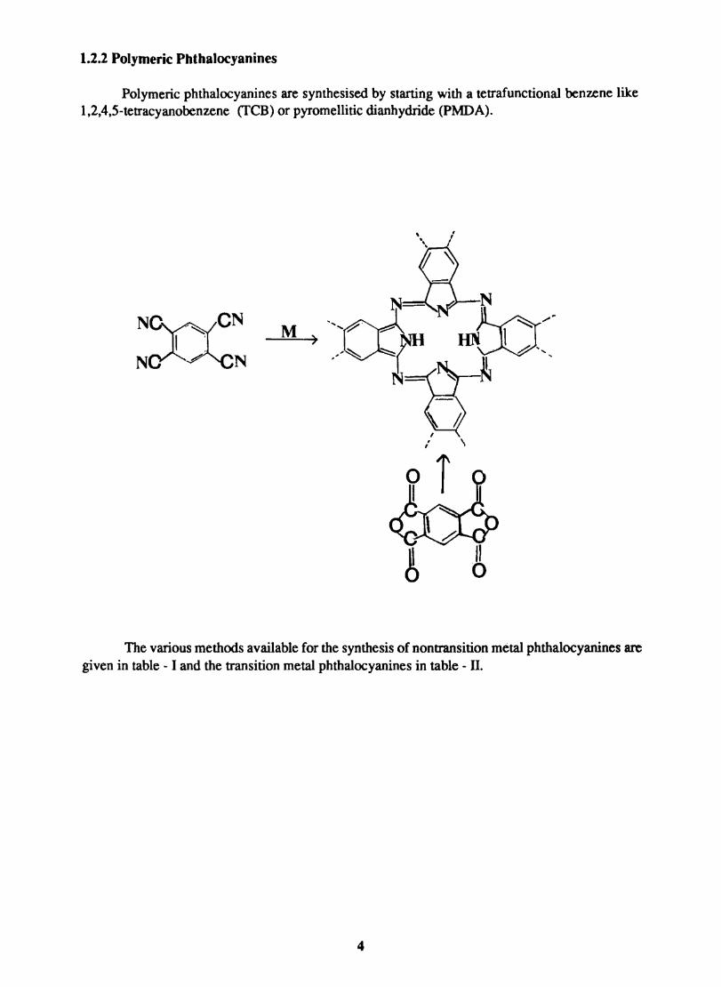
1.2.2 Polymeric Phthalocyanines
Polymeric phthalocyanines are synthesised by starting with a tetrafunctional benzene like 1,2,4,5-tetracyanobenzene (fCB) or pyromellitic dianhydride (PMDA).
,
N~~CN I :
N .# N
, " \
The various methods available for the synthesis of non transition metal phthalocyanines are given in table - I and the transition metal phthalocyanines in table - II.
4
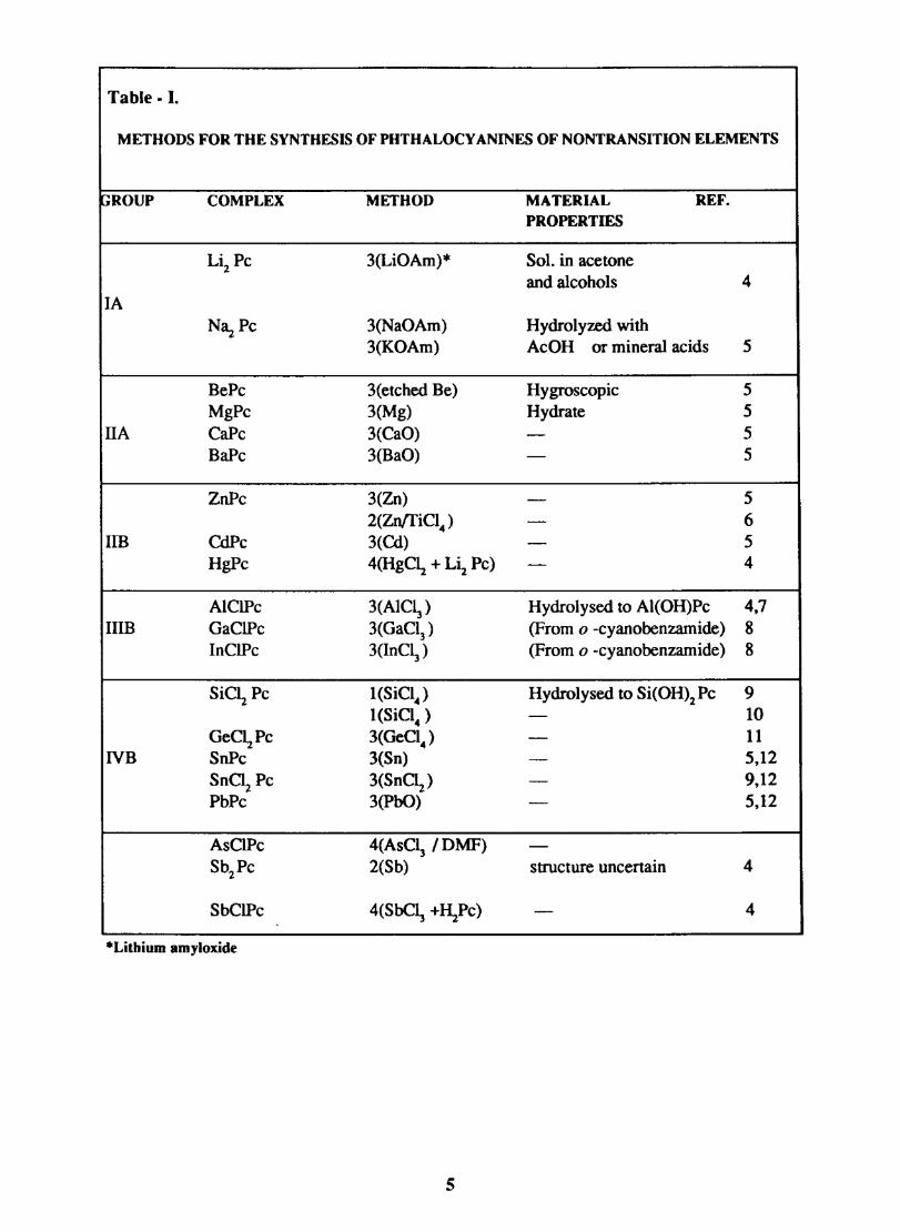
Table - I.
METHODS FOR THE SYNTHESIS OF PHTHALOCY ANINES OF NONTRANSITION ELEMENTS
GROUP COMPLEX METHOD MATERIAL REF. PROPERTIES
Li2Pc 3(LiOAm)* Sol. in acetone and alcohols 4
lA N3.z Pc 3(NaOAm) Hydrolyzed with
3(KOAm) AcOH or mineral acids 5
BePc 3(etched Be) Hygroscopic 5 MgPc 3(Mg) Hydrate 5
HA CaPc 3(CaO) - 5 BaPe 3(BaO) - 5
ZnPc 3(Zn) - 5 2(ZnffiC14 ) - 6
Im CdPc 3 (Cd) - 5 HgPc 4(HgC\ + Li2 Pc) - 4
AIClPc 3(AIC~) Hydrolysed to Al(OH)Pc 4,7 HIB GaClPc 3(GaC13 ) (From 0 -eyanobenzamide) 8
InClPc 3(InC~) (From 0 -cyanobenzamide) 8
SiC~ Pe I(SiCI4 ) Hydrolysed to Si(OH)2PC 9 I(SiCi4 ) - 10
GeC~Pc 3(GeCI4 ) - 11 NB SnPc 3(Sn) - 5,12
SnCi2 Pe 3(SnC\) - 9,12 PbPc 3(PbO) - 5,12
AsClPc 4(AsC~ /DMF) -Sb2Pc 2(Sb) structure uncertain 4
SbClPc 4(SbC~ +~Pe) - 4
*Litbium amyloxide
5
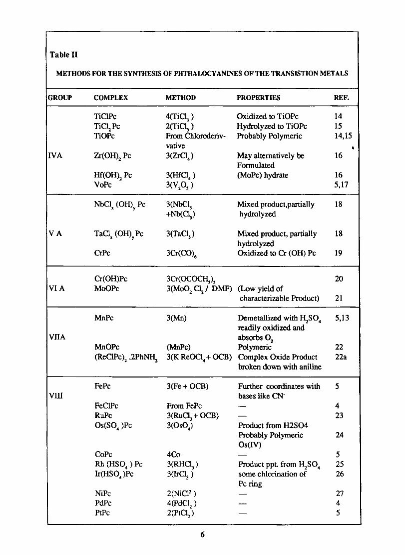
Table 11
METHODS FOR THE SYNTHESIS OF PHTHALOCYANINES OF THE TRANSISTION METALS
GROUP COMPLEX METHOD PROPERTIES REF.
TiClPc 4(TiC~ ) Oxidized to TiOPc 14
TiC~Pc 2(Ti~ ) Hydrolyzed to TiOPc 15 TiOPc From Chloroderiv- Probably Polymeric 14,15
vative • IVA Zr(OH)2 Pc 3(ZrCI
4) May alternatively be 16
Fonnulated Hf(OH)2 Pc 3(Hf°4 ) (MoPc) hydrate 16 VoPc 3(V2OS
) 5,17
NbClx (OH)y Pc 3(NbC~ Mixed product,partially 18 +Nb(CIs) hydrolyzed
VA TaCl (OH) Pc 3(TaCIs) Mixed product, partially 18 x y
hydrolyzed CrPc 3Cr(CO)6 Oxidized to er (OH) Pc 19
Cr(OH)Pc 3Cr(OC~)3 20 VIA MoOPc 3(Mo02 C12! DMF) (Low yield of
characterizable Product) 21
MnPc 3(Mn) Demetallized with I\S04 5,13 readily oxidized and
VllA absorbs O2 MnOPc (MnPc) Polymeric 22 (ReClPc)2 .2Ph~ 3(K ReOCl4 + OCB) Complex Oxide Product 22a
broken down with aniline
FePc 3 (Fe + OCB) Further coordinates with 5 VID bases like CN-
FeClPc From FePc - 4 RuPc 3(RuC~ + OCB) - 23 OS(S04 )Pc 3(OS04) Product from H2S04
Probably Polymeric 24 Os (IV)
CoPc 4Co - 5 Rh (HS04) Pc 3(RHCI3) Product ppt. from I\S04 25 Ir(HS04)Pc 3(IrC~ ) some chlorination of 26
Pc ring NiPc 2(NiCF) - 27 PdPc 4(PdC12 ) - 4 PtPc 2(PtClz) - 5
6
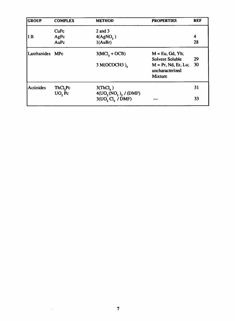
GROUP COMPLEX METHOD PROPERTIES REF
CuPc 2and3 IB AgPc 4(AgN03 ) 4
AuPc I(AuBr) 28
Lanthanides MPc 3(MC~ +OCB) M = Eu. Gd. Vb; Solvent Soluble 29
3 M(OCOCH3 )3 M = Pr, Nd, Er, Lu; 30 uncharacterized Mixture
Actinides ThC~Pc 3(ThC14 ) 31 U02 Pc 4(U0 z (NO] )2 I (DMF)
3(U0z <\ I DMF) - 33
7
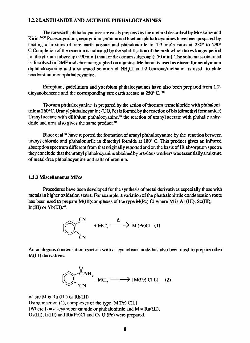
1.2.2 LANTHANIDE AND ACTINIDE PHTHALOCY ANINES
The rare earth phthalocyanines are easil y prepared by the method descri bed by Moskalev and Kirin.36
,37 Praseodymium, neodymium, erbium and lutetium phthalocyanines have been prepared by heating a mixture of rare earth acetate and phthalonitrile in 1:3 mole ratio at 280" to 29{)0 C.Completion of the reaction is indicated by the solidification of the melt which takes longer period for the yttrium subgroup (-9Omin.) than for the cerium subgroup (-50 min), The solid mass obtained is dissolved in DMF and cbromatographed on alumina. Methanol is used as eluent for neodymium diphthalocyanine and a saturated solution of NH
4CI in 1:2 benzene/methanol is used to elute
neodymium monophthalocyanine.
Europium, gadolinium and ytterbium phthalocyanines have also been prepared from 1,2-dicyanobenzene and the corresponding rare earth acetate at 250" C. 38
Thorium phthalocyanine is prepared by the action of thorium tetrachloride with phthalonitrile at 260" C. Uranyl phthalocyanine (U02PC) is fonned by the reaction ofbis (dimethyl fonnamide) Uranyl acetate with dilithium phthalocyanine.39 the reaction of uranyl acetate with phthalic anhydride and urea also gives the same product.40
Bloor et al 41 have reported the formation of uranyl phthalocyanine by the reaction between uranyl chloride and phthalonitrile in dimethyl formide at 180" C. This product gives an infrared absorption spectrum different from that originally reported and on the basis of IR absorption spectra they conclude that the uranyl phthalocyanineobtained by previous workers was essentially a mixture of metal-free phthalocyanine and salts of uranium.
1.2.3 Miscellaneous MPcs
Procedures have been developed for the synthesis of metal derivatives especially those with metals in higher oxidation states. For example. a variation of the phathalonitrile condensation route has been used to prepare M(Ill)complexes of the type M(pc) a where M is Al (Ill). Sc(lll), In(ID) or Yb(lll).42.
uCN !l +MC~ --~) M(Pc)CI (1)
CN
An analogous condensation reaction with 0 -cyanobenzamide has also been used to prepare other M(llI) derivatives.
o:~-NH 2 + MCl
3 __ ~) [M(Pc) Cl L] (2)
CN
where M is Ru (ITI) or Rh(III) Using reaction (1), complexes of the type [M(Pc) ClL] (Where L = 0 -cyanobenzamide or phthalonitrile and M = Ru(III), Os(llI), h(llI) and Rh(Pc)CI and Os 0 (Pc) were prepared.
8
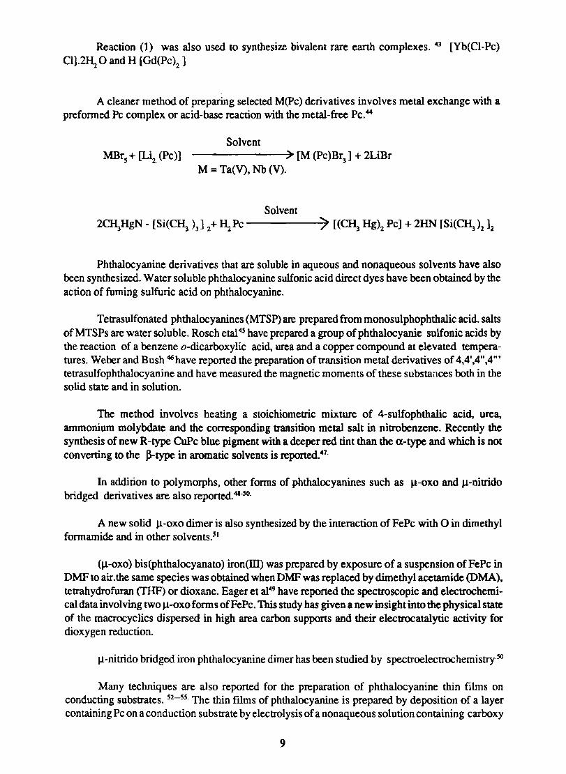
Reaction (1) was also used to synthesize bivalent rare earth complexes. 43 [Yb(CI-Pc) CI].2~ 0 and H [Gd(Pc)2 ]
A cleaner method of preparing selected M(Pc) derivatives involves metal exchange with a preformed Pc complex or acid-base reaction with the metal-free Pc.44
Solvent MBrs + [Li2 (Pc)] ) [M (Pc)Br
3] + 2LiBr
M = Ta(V), Nb (V).
Solvent 2~HgN - [Si(C~ )3] 2+ ~Pc -----)~ [(C~ Hg)2 Pc] + 2HN [Si(C~)212
Phthalocyanine derivatives that are soluble in aqueous and nonaqueous solvents have also been synthesized. Water soluble phthalocyanine suIfonic acid direct dyes have been obtained by the action of fuming sulfuric acid on phthalocyanine.
Tetrasulfonated phthalocyanines (MTSP) are prepared from monosulphophthalic acid. salts of MTSPs are water soluble. Rosch etal4S have prepared a group of phthaIocyanie sulfonic acids by the reaction of a benzene o-dicarboxylic acid, urea and a copper compound at elevated temperatures. Weber and Bush 46 have reported the preparation of transition metal derivatives of 4,4',4",4'" tetrasulfophthalocyanine and have measured the magnetic moments of these substances both in the solid state and in solution.
The method involves heating a stoichiometric mixture of 4-sulfophthaIic acid, urea, ammonium molybdate and the corresponding transition metal salt in nitrobenzene. Recently the synthesis of new R-type CuPc blue pigment with a deeper red tint than the a-type and which is not converting to the ~type in aromatic solvents is reported. 47.
In addition to polymorphs, other forms of phthaIocyanines such as ~-oxo and J.l-nitrido bridged derivatives are also reported.4I·so.
A new solid J.l-oxo dimer is also synthesized by the interaction of FePc with 0 in dimethyl formarnide and in other solvents.sl
(J.l-oxo) bis(phthalocyanato) iron(III) was prepared by exposure of a suspension of FePc in DMF to air.the same species was obtained when DMF was replaced by dimethyl acetamide (DMA). tetrahydrofuran (THF) or dioxane. Eager et a149 have reported the spectroscopic and electrochemical data involving two J.1-oxo forms of Fe Pc. This study has given a new insight into the physical state of the macrocyclics dispersed in high area carbon supports and their electrocatalytic activity for dioxygen reduction.
J.l-nitrido bridged iron phthalocyanine dimer has been studied by spectroelectrochemistry-so
Many techniques are also reported for the preparation of phthalocyanine thin films on conducting substrates. 52-SS. The thin ftlms of phthalocyanine is prepared by deposition of a layer containing Pc on a conduction substrate by electrolysis of a nonaqueous solution containing carboxy
9
phthalocyanine and supporting electrolyte. Another technique used to prepare thin films is by electrolyte micelle disruption method.56 In this case the film formation consists of the following stages: (1) sollubilization (or dispersion) of a water-insoluble chemical by a surfactant with ferrocenyl moiety (2) electrochemical oxidation of the ferrocenyl moiety, followed by break upof the micelle (3) release of molecules (orpartic1es) from the aggregates and then (4) deposition of the water-insoluble substance on the electrode surface. These methods facilitate the preparation of electrodes with controllable layer thickness,uniformity, adhesion and durability.
1.3 Purification of Metal Phthalocyanines
A formidable hurdle in phthalocyanine chemistry is the isolation of phthalocyanine in its pure form. Every method of synthesis of phthalocyanines results in the contamination of the product with unreacted materials such as phthalic anhydride, urea, phthalimide or phthalonitrile.The phthalocyanine formed itself is a mixture of oligomers. Classical purification techniques such as acid and alkali washing, solvent washing, solvent extraction, regeneration by concentrated ~S04 ,vacuum sublimation and chromatography are used to purify the crude phthalocyanines.
The first step in the purification of phthalocyanine involves washing with 10% caustic soda,2M HCI, methanol and benzene successivey. The solid mass so obtained is slurried in concentrated sulphuric acid and dropped on ice. The precipitate which is essentially a mixture of various polymorphs of metal phthalocyanines is washed with water and dried. Though this method is sufficient for the removal of unreacted materials, the different polymorphs and oligomers cannot be separated.
Linstead et al 56 have reported that phthalocyanines sublime under vacuum slowly at 5500C and rapidly at 580" C. This method is found suitable to prepare very pure crystals and thin films of MPcs. The vapour is deep blue and the crystals formed have the purple lustre characteristic of the a-form. This films ofMPcs of thickness 1000-4000"- can be conveniently prepared by sublimation technique.
The phthalocyanines especially rare earth phthalocyanines are found to be mixtures of complexes having different compositions. Neodymium, praseodymium, erbium. lutetium and lanthanum phthalocyanines give two forms, mono and diphthalocyanines. The several forms ofPcs can often be separated only by chromatography.5I.59.
The rare earth phthalocyanine formed is dissolved in DMF and passed through a column of aluminium oxide. Methanol is used as the eluent Separationis also achieved by eluting with a saturated solution of NH4Cl in a 1:2 benzene-methanol mixture. Neodymium phthalocyanine is purified by this method. Lutetium diphthalocyanine is purified by chromatography over neutral alumina with DMF as eluent. It was rechromatographed over silica gel using chloroform as eluent Walton et al 60 purified lutetium and ytterbium diphthalocyanines avoiding time consuming chromatographic elution techniques. They have isolated the Pcs from the mixture by extraction into chloroform.The green powder obtained by solvent evaporation was washed with acetic anhydride. methanol and acetone to remove traces of persistent impurities.
1.4.0 Physicochemical Characteristics of Metal Phthalocyanines
1.4.1 Crystal Structure and Polymorphism
The X-ray studies of crytals of copper,nickel, platinum, cobalt. iron and managanese phthalocyanines show that the crystals are all monoclinic. having a centre of symmetry.
10
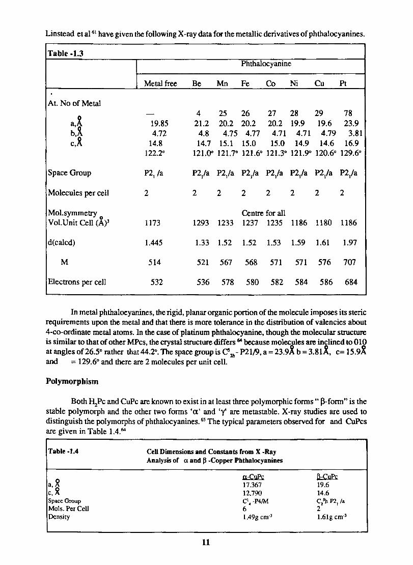
Linstead et al 61 have given the following X -ray data for the metallic derivatives of phthalocyanines.
Table -1.3 Phthalocyanine
Metal free Be Mn Fe Co Ni Cu Pt . At. No of Metal
- 4 25 26 27 28 29 78 a,x' 19.85 21.2 20.2 20.2 20.2 19.9 19.6 23.9 b.~ 4.72 4.8 4.75 4.77 4.71 4.71 4.79 3.81 c,R 14.8 14.7 15.1 15.0 15.0 14.9 14.6 16.9
122.2° 121.00 121.7° 121.6° 121.3° 121.9<> 120.6° 129.6°
Space Group P21 /a P2/a P2/a P2/a P2/a P2/a P2/a P2/a
Molecules per cell 2 2 2 2 2 2 2 2
Mol. symmetry Centre for all Vol.Unit Cell (ly 1173 1293 1233 1237 1235 1186 1180 1186
d(calcd) 1.445 1.33 1.52 1.52 1.53 1.59 1.61 1.97
M 514 521 567 568 571 571 576 707
Electrons per cell 532 536 578 580 582 584 586 684
In metal phthalocyanines, the rigid, planar organic portion of the molecule imposes its steric requirements upon the metal and that there is more tolerance in the distribution of valencies about 4-co-ordinate metal atoms. In the case of platinum phthalocyanine, though the molecular structure is similar to that of other MPcs. the crystal structure differs 64 because molec~des are inclined to 010 at angles of 26.5° rather that 44.2°. The space group is Cs 2b - P2119, a=23.9A b =3.81K. c= 15.9X and = 129.6° and there are 2 molecules per unit cell.
Polymorphism
Both I\Pc and CuPc are known to exist in at least three polymorphic forms" J}-form" is the stable polymorph and the other two forms 'a' and '"'(' are metastable. X-ray studies are used to distinguish the polymorphs of phthalocyanines. 65 The typical parameters observed for and CuPcs are given in Table 1.4.64
Table -1.4
a.~ c.~ Space Group Mols. Per Cell Density
CeU Dimensions and Constants from X -Ray Analysis of a and ~ -Copper Phthalocyanines
11
a-CuPc 17.367 12.790 C\ -P4/M 6 1.49g cm-3
6-CUPC 19.6 14.6 C/h P2l/a 2 1.61g cm-3
The a-form of metal phthalocyanine is formed in both the solvent and melt methods of synthesis. Heating to 2000 C reconverts the a-form to the ~-form. The a - ~ transition can be followed from the temperature-conductivity measurements. The sublimation product of copper phthalocyanine at 550"C is the ~-form. The ~form can be converted to the a-form by dissolution in concentrated sulphuric acid followed by precipitation with water. The a-form is also obtained from the ~-form by the permutoid swelling process ie. by adding the J3-fonn pigment to 68% sulphuric acid, forming a yellowish green sulphate, followed by drowning in water, to hydrolyse the sulphate. The precipitate formed is of the a-form. The polymorphs can be identified both quantitatively and qualitatively by infrared spectroscopy'6S The enthalpy difference between and CuPc has been measured by isothermal calorimetry.66.
The third polymorph 'Y-CuPc first reported by Estates 67, is obtained by stirring crude CuPc
with sulphuric acid of less than 60% concentration. Salts of CuPc made by slurrying it in nitrobenzene and adding a non-oxidising strong mineral acid, followed by fllteration and hydroysis of the filtered salt by water also produced the 'Y-type crystal. The solvent unstable forms of a-and 'Y-phthalocyanines were converted to stable a or'Y polymorphs by pasting with 50-100% I-I"S04 in the presence of an undisclosed stabilizer.6
&
1.4.2 Spectral Characteristics
Absorption Spectra
The absorption maximum of phthalocyanines is calculated by assuming the TI-electrons to be one dimensional free electron gas, resonating between two equivalent limiting structures of the phthalocyanine ring with constant potential energy along its lenght.69.70.
In the normal state, the stablest energy states of the electron gas, each contains two electrons in accordance with Pauli' s exclusion principle. The remaining states are empty. The existence of the first absorption band is a consequence of the jump of a TI - electron from the highest energy level. The spectrum of the phthalocyanine in the visible region is composed of at least seven bands, the main absorption occuring between 6000 and 7000 A.
The infrared spectra of metal phthalocyanines are reported irt media such as nujol and also the form of solid fllms formed by sublimation.71;n Infrared spectra of the two polymorphic forms of CuPc show distinct difference in the 12.5 to 14.5 ~ m range. IR spectroscopy also helps to study the effect of electron donors on phthalocyanines.73•7S.
1.4.3 Magnetic Properties
The magnetic susceptibility measurements on metal phthalocyanines give information relating to their structure and the nature of bonding of the central metal atom with the surrounding isoindole nitrogen atoms. NiPc is paramagnetic has a magnetic moment of 1.73 BMg·1
•76 The
magnetic susceptibility of cobalt, iron, managanese and vanadyl phthalocyanines are 2.9,10.5 and 1.6 Bohr magnetons respectively.
12
1.4.4 Electrical characteristics of MPcs
Phthalocyanines are intrinsic semiconductors and the current carriers are mobile n-electrons. The temperature dependence of conductivity follows the relation
o = 0 0 exp (-Ea/kT) where 0 = Specific conductivity at temperature T in ohm -1 cm-1
0 0 = specific conductivity at infinite temperature Ea = Activation energy and R= Gas constant
Pressure has only a little effect on the conductivity ofMPcs. Replacement of the two central hydrogen atoms by a metal atom has little effect upon the energy gap which lies between 1.5 to 1.7 eV and is sensitive to the atomsphere surrounding the sample. Replacement of the two central hydrogen atoms by a metal atom has little effect upon the energy gap which lies between 1.5 to 1.7 e V and is sensitive to atomsphere surrounding the sample.
1.4.5 Aggregation of MPcs
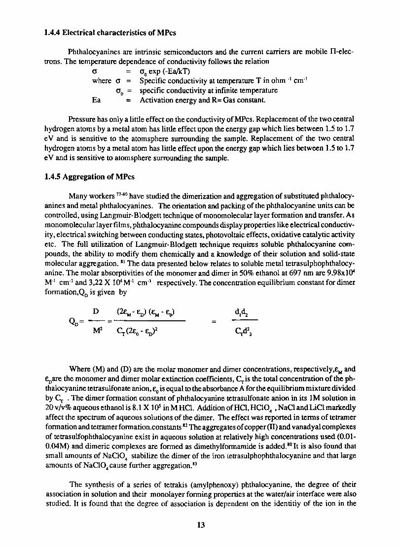
Many workers 77-80 have studied the dimerization and aggregation of substituted phthalocyanines and metal phthalocyanines. The orientation and packing of the phthalocyanine units can be controlled, using Langmuir-Blodgett technique of monomolecular layer formation and transfer. As monomolecular layer films, phthalocyanine compounds display properties like electrical conductivity, electrical switching between conducting states, photovoltaic effects, oxidative catalytic activity etc. The full utilization of Langmuir-Blodgett technique requires soluble phthalocyanine compounds, the ability to modify them chemically and a knowledge of their solution and solid-state molecular aggregation. 81 The data presented below relates to soluble metal tetrasulphophthalocyanine. The molar absorptivities of the monomer and dimer in 50% ethanol at 697 nm are 9.98xl04 M-1 cm-1 and 3,22 X 10⁴M-1 cm-! respectively. The concentration equilibrium constant for dimer formation,QD is given by
D (~- En) (Ew - EO> QD= -- = -------- =
M2 ~ (2£0 - En)2
Where (M) and (D) are the molar monomer and dim er concentrations, respectively,Ew and Eoare the monomer and dimer molar extinction coefficients, ~is the total concentration of the phthalocyanine tetrasulfonate anion, Eo is equal to the absorbance A for the equilibrium mixture divided by ~ . The dim er formation constant of phthalocyanine tetrasulfonate anion in its 1 M solution in 20 v/v % aqueousethanolis 8.1 X lOS in M HCl. Addition of HCI, HCI0. ,NaClandLiClmarkedly affect the spectrum of aqueous solutions of the dim er. The effect was reponed in terms of tetramer formation and tetramer formation.constants·82 The aggregates of copper (IT) and vanadyal complexes of tetrasulfophthalocyanine exist in aqueous solution at relatively high concentrations used (0.01-O.04M) and dimeric complexes are formed as dimethylfonnamide is added. 10 It is also found that small amounts of NaCI0
4 stabilize the dimer of the iron tetrasulphophthalocyanine and that large
amounts of NaC104 cause funher aggregation. 83
The synthesis of a series of tetrakis (amylphenoxy) phthalocyanine, the degree of their association in solution and their monolayer fonning properties at the water/air interlace were also studied. It is found that the degree of association is dependent on the identitiy of the ion in the
13
phthalocyanine cavity. The phthalocyanine aggregate forms stable monomolecular films whose packing densities at the air/water interface relate to .the degree of association.
1.5.0 Technological Applications of Phthalocyanines
1.5.1 Pigments and Dyes
The phthalocyanines are widely used in textile, paint, printing ink and plastic industries. The noncolorant applications include catalysts, lubricating greases, analytical reagents, clinical diagnostic agents and electrical devices.
Although the shade range of the phthalocyanines is rather limited and covers only the bluegreen regions of the spectrum, their excellent fastness to light, and high absorptivity render them apt for many appliations. The insolubility of phthalocyanines necessitates preparation of soluble derivatives for application as dyes for textile fibres.Phthalocyanine pigments in the fonn of aqueous dispersions is used in pad-dyeing with resin emulsions. Because of their excellent stability to acids, alkalis and solvents phthalocyanines are particularly useful in spin dying. They have also been used in coloring polyvinylchloride fibres, viscose, cuprommonium cellulose, nylon, 'perIon L', etc.
Both phthalocyanine blue (copper phthalocyanine) and phthalocyanine green (copper pol ychloro phthalocyanine) have found wide use as paint pigments. Metal surfaces can be coated by forming the metal phthalocyanine directly on them.804 Large metal surfaces can be coated with metal phthalocyanine by dipping in a solution of phthalonitrile in acetone, drying, and subjecting the metal to temperatures of around 3500 C in a sealed oven. The coating is very adherent and the shade of color depends on the metal used.
Phthalocyanines have been used to colorrubber, poly styrene, poly urethane foams, cellulose acetate sheeting, polysters, polyamides, vinylchloride polymers and other plastic and polymeric materials. IS-BB Copper phthalocyanine-sodium sulfonate have been used in photographic proceses to produce colored prints. Copper phthalocyanine is also used as a certified food color.89
1.5.2 Analytical Reagent
Copper phthalocyanine in concentrated sulphuric acid has been used as a reagent for the detection of oxidizing agents such as N0
2- , N0
3- ,CIO]- ,Br0
3-,I0
3- , Cr
20/,-- and Mno
Copper tetrasulphophthalocyanine is used as a redox indicator in the cerimetric detennination of iron (ID and ferrocyanide 90. It was found that copper 4,4',4",4'" tetrasulphophthalocyanine (CuTSP) is a suitable indicatior for the titration ofFe(ID in 0.5 -2 .5M HCI or ~S04 or Fe(CN)64- in 0.5N ~S04 with O.OIN to O.OOlN Ce +4 • CuTSP is stable towards HC!, ~S04 and ~P04' A 0.1 % solution of CuTSP is used as the indicatior solution.
1.5.3 Catalyst
The first mention of phlhalocyanines as catalyst is on the activation of molecular hydrogen 91 and found that crystals of phlhalocyanine and copper phthalocyanine catalyse atomic interchange between molecular hydrogen and water vapour, and oxygen.92 Phthalocyanines catalyse the oxidation of many organic compounds.93-9s Cobalt, nickel and iron phthalocyanines catalyse the oxidation of a-pinene to verbenone. Nickel phthalocyanine catalyses the autooxidation of saturated ketones such as 2-octanone, 4-heptanone and cyclo hexanone at 120-13O"C to adiketones and aldehyde. The aerobic oxidation of unsaturated fatty acids catalysed by iron and cobalt
14
phthalocyanine has been reported.96 Iron, cobalt, tin and copper phthalocyanines and their derivatives have been used as rubber emulsification catalysts. When cobalt tetrasulphophthalocyanine is attached to poly (vinylamine) it can catalyse the autooxidation of thiols.97
1.5.4 Electrocatalysts
a-Keto acids, eg., pyruvic, phenylpyruvic, a-ketobutyric, a-ketoglutaric and a-keto isocaproic undergo electrocatalysed reduction at carbon past electrode modified with cobalt phthalocyanine.98 CoPc modified electrodes can catalyse numerous electron transfer processes in addition to those of hydrazine and thiol compounds·99 Metal phthalocyanines have received much attention in the electocatalytic reduction of dioxygen,lQO.l02The phthalocyanines assume importance in electrocatalysis for two reasons:
1) Metal phthalocyanines are structural and electronic analogues of porphyrins whose electrochemistry is imponant in understanding electron transfer processes in biological systems.
2) Electrocatalytic reduction of dioxygen is important in fuel cells. Of the metal complexes of phthalocyanine, iron and cobalt have been examined in detail. 103
Because of the lower solubility of phthalocyanines, water soluble phthalocyanines such as tetrasulphophthalocyanine 104 and tetracarboxy phthalocyanine 105 have been used as facile catalysts in aqueous medium. The electrocatalytic activity of dioxygen reduction was improved at a glassy carbon electrode when modified with polypyrrole/tetrasulfonatophthalocyaniato cobalt electrode. 106 The glassy carbon/polypyrrole/cobalt tetrasulfophthalocyanine (GC/PPY /CoTSP) electrode was formed by electropolymerization of pyrrole on a glassy carbon electrode in methanol solution containing CoTSP. Oxygen reduction reaction at the GC/PPY/CoTSP electrode in O.5M ~SO 4 showed about O.5V more anodic onset 'potential than the value obtained with a GC electrode in the same medium.
The reduction of dioxygen at iron tetrasulfonatophthalocyanine (FeTSP) incorporated into polypyrrole was also studied.10? It was found that thicker fllms are stable and mediate four-electron reduction of dioxygen. It was indicated that dimeric FeTSP species are responsible for the marked shift in the reduction onset potential.
Polymeric iron phthalocyanine precipitated on activated carbon, when heated to 200-5000 C showed a higher rate of deactivation for the electrochemical reduction of dioxygen. 108
.
The iron, cobalt, copper phthalocyanine function as a catalyst layer and oxygen sensor in fuel cells and air batterie.109 A porous electrocatalyst material was prepared by soaking activated carbon in iron phthalocyanine pyridine solution and in perfluorodecalin - CCI solution and then mixing with P1FE. The material in the form of sheet was bonded on a nickel mesh. The electrode was used in a zinc-air battery having a discharge current density of 63 mAlcm2 •
15
1.5.5 Active Layers on Chemically Modified Electrodes
Electrodes derived from different types of phthalocyanines have been fabricated.lol.lI~ 112 powdered carbon or metal is coated with the phthalocyanines by chemical vapour deposition, solvent evaporation or electrophoretic deposition. the powder of the same material has also been pressed with crystalline phthalocyanines in to composite pellets. Various metal and semiconductor su bstrates demonstrated greatly enhanced activity for the electrolysis of the benzoquinone/hydroquinone redox couple when coated with multimolecular layers of chlorogallium phthalocyanine.113
Exchange current density on GaPc-CUAu electrode irradiated with -100mW/cm2 polychromatic light were -1()3 times greater than on plain gold electrode. The role of GaPc-Clin activating the substrate surface is also reported. The use of chemically modified carbon paste electrodes,which are modified by the incorporation of cobalt phthalocyanine is able to oxidize or reduce solute species which are themselves electrolysed only irreversibly at conventional electrode surfaces." These electrodes decrease the overpotential for the oxidation of thiols 114, hydrazinellS, a -keto acids and oxalic acid. A glassy carbon electrode modified with CoPc can be efficiently used as a liquid chromatographic detector for the clinical assay of oxalic acid and a-ketoacids in blood and urine. Faulkneret al t I 6,J17 have studied in detail the faradaic processes taking place on Pc modified electrode surfaces. Nearly reversible kinetics and a high degree of selectivity for the electrode process are observed on these films.
Photoreduction of dioxygen takes place on certain phthalocyanines, when they are vacuum deposited to a thickness of 100-1000 1 on polished graphite. Photooxidation of oxalate takes place on 1 m thick films of CuPc deposited on Pt.IIB
1.5.6 Photovoltaic and Photogalvanic Devices
Phthalocyanines show photoconductivity. The photoconductive and photovoltaic properties ofPcs have been extensively studied for use in electrophotographic systems,diodes,laser printers, photovoltaic cells, photoelectrochemical devices and vidicon tubeS.1I9•123
MnPe can be considered as a model compound for the study of photocatalytic decomposition of water in biochemical processes. Cobalt cm tetrasulfophthalocyanine (CoTSP) can be covalently bound to the surface of titanium dioxide particles. Upon irradiation with light having energy exceeding the band gap energy of TiOz ' Co(II) TSP is reduced to Co(I) TSP. This photochemical reduction is reversible in presence of dioxygen. The photochemical stability and the high quantum yields for 02 reduction makes this newly developed material applicable as a potent and stable oxidation catalyst. The interest shown in these systems is due to the simultaneous fonnation of dihydrogen and dioxygen from water. An overall transfer of conduction band electrons e-ell and valence band holes h\B is required to achieve this direct storage of solar energy in the form of chemical energy. The reactions taking place are:
> 1\ ( ) + 20H-8CJ cathodic
------>.»02 ( ) +4H+aq anOdic
Cobalt tetrasulfophthalocyanine covalently bound on the surface of titanium dioxide particles act as efficient electron relays to compete with the e-/h+ recombination and thus achieve reasonable but still rather small,quantum yields.
16
In photocells, with phthalocyanine as the active material under an externally impressed negative bias, the efficiency in energy conversion can reach about 25%.
1.5.7 Electrocbromic Displays
Electrochromic (Electrochemichromic EC) effect is the production, by faradaic reaction, of a color change in materials localised at an electrode surface. A thin film of lanthanide diphthalocyanine deposited on optically transparent electrode shows change in absorption spectrum of polarisation in contact with an aqueous electrolyte. 126,1 27 Rare earth phthalocyanine can be sublimed onto conducting glass and can therefore be used as materials for EC displays. These electrochemichromic materials are also useful for full-colour imaging and graphic and alphanumerics displays.121 The rapid decay of EC characteristics of rare earth diphthalocyanine film electrodes on potential cycling in neutral aqueous solution has been considerably retarded by using ethyleneglycol as solventl29
1.5.8 Batteries
Phthalocyanines and phthalocyanine derivatives have been used as cathode materials in batteries especially in fuel cells and air cathode batteries. In batteries the porouselectroconductive material is loaded with metal phthalocyanine and a perfluoro compound. This composite material is used as the catalyst layer. 130,131
1.5.9 Gas Sensors
Devices based on metal phthalocyanine such as PbPc show useful response towards N02. A thin film PbPc sensor has successfuly been used to monitor NO" produced by shon firing in coal mines 132pc based devices offer much promise as resistance modulating sensors for toxic gases. They are thus complementary to metal oxide devices which are most useful in the detection of flammable gases. The lanthanide diphthalocyanine complexes have been used as gas detectors for acidic and basic gases. m
I.S.10 Electropbotograpby
Electrically conductive substances are coated with photoconductive layers made up ofPcs dispersed in a binder resin, The plates show high sensitivity, improved durability and excellent imaging characteristics. 134
17
CHAPTERII
EXPERIMENTAL
Synthesis and characterisation of metal phthalocyanines Synthesis of copper, cobalt and nickel phthalocyanines
A mixture of phthalic anhydride 5.9g (0.4 mmol), urea 9.6g (1.6 mmol) and 50mg of ammonium molybdate and a speck of ammonium chloride were heated in nitrobenzene at refluxing temperature (205° C) for 2 h. The nitrobenzene was recovered by distillation at reduced pressure. The crude product so obtained was washed several times with methanol until it was free of nitrobenzene. This was again washed with 10% NaOH, 2M Hel to remove any unreacted acid and metal salt, and finally washed with distilled water till the washing were neutral. The solid mass so obtained was slunied in concentrated sulphuric acid and dropped on ice. The precipitate fonned was filtered and dried.
The metal phthalocyanines so obtained were further purified by soxhlet extraction with benzene, acetone and DMF. The material was finally purified in a sublimation chamber. The pure phthalocyanine was deposited onto a glass plate at 200"C under about 10""4 tOIT.
Phthalonitrile Process
Iron and zinc phthalocyanines were prepared by heating phthalonitrile and the corresponding metal chloride in the molar ratio 4: 1 at 180-190" for 2h in quinoline. The metal phthalocyanine so obtained was purified by the procedure described in the previous section. The unreacted phthalonitrile was removed by soxhlet extraction with benzene.
Lanthanum phthalocyanine
Rare earth acetates prepared from pure grade oxide were used for the preparation of lanthanide phthalocyanines. Lanthanum acetate was prepared from its oxide by the following procedure. 135
Lanthanum oxide (Indian Rare Earths Ltd. Udyogamandal) was ignited for 3 h in a silica crucible. This oxide was cooled and refluxed with 200 ml of acetic anhydride for 6 h. After 2 h of refluxing the solid mass was broken up thoroughly and refluxing continued for 4 h. The lanthanum acetate formed was filtered out and dried in vacuum.
A mixture of Ig of lanthanum acetate (0.5 mmol) and 3g ofphthalonitrile (2.6 mmol) were heated at 280 - 29{)0 C in a furnace for 2 h. The dark blue solid mass obtained was washed with benzene to remove any unreacted phthalonitrile. This was filtered and the solid dissolved in 200 ml DMF. This solution was then passed through a column of neutral alumina. The pigment was adsorbed on the upper part of the column. Methanol was used to elute the fraction containing the blue pigment. The solution was evaporated to dryness and the residue was dried at 1000 C for 1 h.
Tetrasodium salt of cobalt(II) 4,4',4" ,4'" - tetrasulfophthalocyanine dihydrate.
The procedure is a modification of the method developed by Weber and Busch.1J6. The monosodium salt of 4-sulfophthalic acid (4.7g, O.09mol), urea(58g, O.97mol), ammonium mo-
18
lybdate (0.68g, 0.0006 mol), and cobalt(lI) sulphate, 7-hydrate (13.6g, 0.048 mol) were ground together to a fine powder. Nitrobenzene (40 ml) was heated to 180" C in a 500 ml two-necked flask fitted with a thermometer and a condenser and a stopper. The solid mixture was added slowly with stirring keeping the temperature between 160" and 190" C.
The mixture was heated for 6 h at 180" C. The crude product was ground and washed with methanol. The washed solid was added to 1 L of 1 N hydrochloric acid saturated with sodium chloride. This was heated to boiling,cooled and filtered. The resulting solid was dissolved in 700 ml of 0.1 N sodium hydroxide. The solution was heated to 90" C and insolubles separated by filtration. Sodium chloride (270g) was added to the solution.At this point the solid product precipitated. This was centrifuged and the solid was washed with 80% aqueous ethanol refluxed for 4 h in 200 ml absolute ethanol and cooled. The product was filtered and dried at 80" C.
Complexes of nickel (11), copper (11) and Pe(lll) were prepared by procedures similar to that used for Co(II).
2.1.2 CHARACTERISATION OF METAL PHTHALOCYANlNES
The various metal phthalocyanines were characterized by the following physical and chemical methods. Nitrogen was estimated by standard Kjeldahl method. 137
Sulphur content of the compounds was estimated by Schoniger oxygen flask method. m
A weighed sample (0.2g) of the material was placed in the sample cup of the Schoniger flask. It was covered with a strip of ashless filter paper having a wick for ignition. Sodium hydroxide solution (40 ml, 10%) was used as absorbent and 5 ml of 30% hydrogen peroxide was used as oxidant. The sample cup was lowered into the flask and the flask was flushed with oxygen. The wick was ignited and the flaskwas closed by lowering the stopper carrying the cup. After ignition, the contents were thoroughly mixed the solution was acidified with hydrochloric acid and transferred to 250 ml beaker. Sulphate was determined gravimetrically as barium sulphate.
; .. ~\ ':'
19
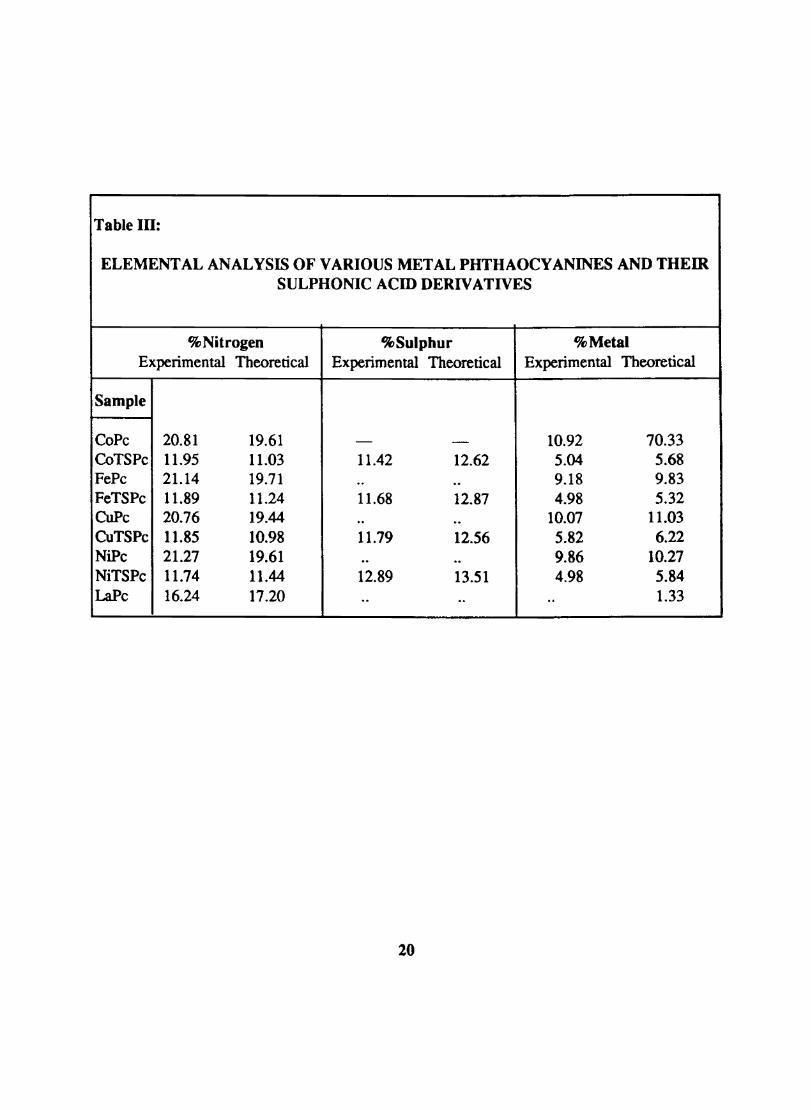
Table Ill:
ELEMENTAL ANALYSIS OF VARIOUS METAL PHTHAOCYANINES AND THEIR SULPHONIC ACID DERIVATIVES
% Nitrogen %Sulphur % Metal Experimental Theoretical Experimental Theoretical Experimental Theoretical
Sample
CoPe 20.81 19.61 - - 10.92 70.33 CoTS Pe 11.95 11.03 11.42 12.62 5.04 5.68 FePc 21.14 19.71 .. .. 9.18 9.83 FeTSPc 11.89 11.24 11.68 12.87 4.98 5.32 CoPe 20.76 19.44 .. .. 10.07 11.03 CuTS Pc 11.85 10.98 11.79 12.56 5.82 6.22 NiPc 21.27 19.61 .. .. 9.86 10.27 NiTSPc 11.74 11.44 12.89 13.51 4.98 5.84 LaPe 16.24 17.20 .. .. .. 1.33
20
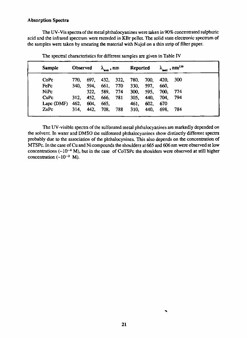
Absorption Spectra
The UV -Vis spectra of the metal phthalocyanines were taken in 90% concentrated sulphuric acid and the infrared spectrum were recorded in KBr pellet. The solid state electronic spectrum of the samples were taken by smearing the material with Nujol on a thin strip of filter paper.
The spectral characteristics for different samples are given in Table IV
Sample Observed A..u ' om Reported A. om139 IIIU '
CoPc 770, 697, 432, 322, 780, 700, 420, 300 FePc 340, 594, 661, 770 330, 597, 660, NiPc 322, 589, 774 300, 595, 700, 774 CuPc 312, 452, 666, 781 305, 440, 704, 794 Lapc (DMF) 462, 604, 665, 461, 602, 670 ZnPc 314, 442, 708, 788 310, 440, 698, 784
The UV -visible spectra of the sulfonated metal phthalocyanines are markedly depended on the solvent. In water and DMSO the sulfonated phthalocyanines show distinctly different spectra probably due to the association of the phthalocynines. This also depends on the concentration of MTSPc. In the case of Cu and Ni compounds the shoulders at 665 and 606 nm were observed at low concentrations (-1 ~ M), but in the case of CoTSPc the shoulders were observed at still higher concentration (-10-3 M).
21
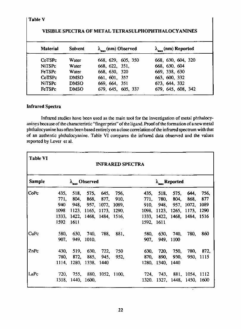
Table V
VISIBLE SPECTRA OF METAL TETRASULPHOPHTHALOCY ANINES
Material Solvent AIftU (nm) Observed AIIIU (nm) Reported
CoTS Pc Water 668, 629, 605, 350 668, 630, 604, 320 NiTSPc Water 668, 622, 351, 668, 630, 604 FeTSPc Water 668, 63O, 320 669, 338, 630 CoTSPc DMSO 661, 601, 357 663, 600, 332 NiTS Pc DMSO 669, 664, 351 673, 644, 332 FeTSPc DMSO 679, 645, 605, 337 679, 645, 608, 342
Infrared Spectra
Infrared studies have been used as the main tool for the investigation of metal phthalocyanin~s because of the characteristic "fingerprint" of the ligand. Proof of the fonnation of a new metal phthalocyanine has often been based entirely on a close correlation of the infrared spectrum with that of an authentic phthalocyanine. Table VI compares the infrared data observed and the values reported by Lever et al.
Table VI INFRARED SPECTRA
Sample A.as Observed A..u; Reported
CoPc 435. 518, 575. 645, 756, 435, 518, 575, 644, 756, 771, 804, 868, 877, 910, 771, 780, 804, 868, 877 940 948, 957, 1072, 1089, 910, 948, 957, 1072, 1089
1098 1123, 1165, 1173, 1290, 1098, 1123, 1265, 1173, 1290 1333, 1422, 1468, 1484, 1516, 1333, 1422, 1468, 1484, 1516 1592 1611 1592, 1611
CuPc 580, 63O, 740, 788, 881, 580, 630, 740, 780, 860 907, 949, 1010, 907, 949. 1100
ZnPc 430, 519, 630, 722, 750 630, 720, 750, 780. 872, 78O, 872, 885, 945, 952, 870, 890, 930. 950. 1115
1114, 1280, 1338, 1440 1280. 1340, 1440
LaPc 720, 755, 880, 1052, 1100, 724, 743, 881, 1054, 1112 1318, 1440, 1600, 1320. 1327, 1448, 145O, 1600
22
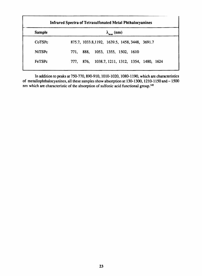
Infrared Spectra of Tetrasulfonated Metal Phthalocyanines
Sample A (nm) mu
CoTS Pc 875.7, 1033.8,1192, 1639.5, 1458,3448, 3691.7
NiTS Pc 771, 888, 1053, 1355, 1502, 1610
FeTSPc 777, 876, 1038.7, 1211, 1312, 1354, 1480, 1624
In addition to peaks at 750-770, 890-910, 1010-1020, 1080-1190, which are characteristics of meta110phthalocyanines, all these samples show absorption at 130-1300, 1210-1150 and - 1500 nm which are characteristic of the absorption of sulfonic acid functional groUp.143
23
CHAPTERIII
ELECTROCHEMICAL STUDIES
Introduction
The surface of an electrode can be characterized by studying the electron transfer across the electrode/electrolyte interface. This also helps in understanding the general rules of electrochemical kinetics and the relation of the electronic structure of the electrode to the electrochemical behaviour. Free charges available for electrical conduction is much lower in semiconductors than in metallic conductors. The electrical field extends deep within the volume of the semiconductor and a space charge region is formed close to its surface. The applied voltage at a semiconductor electrode controls the probability of a surface reaction primarily and not, as at metal electrodes the energy factor.
Depending on whether the semiconductor chosen is n-type or p-type, it can act as electron donor or acceptor, without change in its constitution in an electron transfer reaction. Organic semiconductor electrodes such as phthalocyanines are capable of undergoing faradaic reactions. Faulkner et al 117 have correlated the electrochemical reactivities of several solution species with the relative positions of their energy level and the known band edges and intermediate levels of phthalocyanine thin-film electrodes. They studied the electrochemical properties of thin films of semiconductor electrodes of metal free, zinc and nickel phthalocyanines and found that the facility of charge transfer is determined by the phthalocyanine coverage.
The electrodes modified with layers of electroactive or inactive species is a new tool for the fundamental studies of electron-transfer reactions. Usually the chemical species are attached to the electrode surface and the surface would take on the properties of the attached reagents. Another method is to allow the Faradaic reaction to take place directly on these surfaces. One of the necessary condition for these electrodes is that they should be reasonably conditive. Thin film technology has been utilized for the fabrication of molecular semiconductors with low resistancq. A film of thickness of -l000A deposited over a metallic conductor can provide a current path of sufficiently low resistance, even with bulk resistivities in the over layer as high as 1(1ohm cm.
Metal complexes of organic compounds in general and metal phthalocyanines in particular, received much attention since Jasinski 144,145 reponed that, they are capable of catalysing the electroreduction of dioxygen. Subsequently many types of phthalocyanine-modified electrodes have been fabricated. 110.111, \13, 146,147 Powdered carbon or metal has been coated with the phthalocyanines by chemical vapour deposition, solvent evaporation and electrophoretic deposition. These same powders have also been pressed with crystalline phthalocyanines into composite electrodes. Bulk metal surfaces have been coated by solvent evaporation, by adsorption from solution and also by vacuum deposition. Most of the work based on these electrodes were oriented to study the electrocatalysis of 02 reduction by phthalocyanines. It was Faulkner et al 116 who ftrst investigated whether faradaic process is taking place on the phthalocyanine surfaces. They have fabricated electrodes by evaporating chromium, gold and phthalocyanine in sequence onto a glass substrate in vacuo.ZnPc and FePc showed nearly reversible charge transfer reactions on a cyclic voltammetric time scale. ZnPc and FePc could not efficiently mediate electrode reactions (including 02 reduction) that occurred on Au at potentials more negative than 0.0 V vs SCE, whereas reactions in the positive region could proceed readily.
24
Plasma treatment of MPc layers
A gas can exhibit conductivity only when it possesses free charged particles. The concentration of such charged particles will influence the conductivity of the gas. In the presence of charged carriers, a gas, which is a perfect insulator, starts showing the properties of a conductor. Its insulating capability deteriorates owing to the generation and multiplication of charged particles. This characterized behaviour of the gases in the partially or fully ionized state constitutes the plasma. The electron emission from boundary surfaces, especially from electrodes, facilitates generation of charged particles and contributes to a more intense plasma.
The treatment of a material with plasma results in unique surface modification which can be controlled. This property makes it a useful tool for the modification of surface structure and composition of solid materials. The plasma treaUDent produces chemically active species which results in the surface modification. The thermal treatment of surfaces require temperatures which can either damage or distort the solid being treated, and ultraviolet radiation processes are limited by the spectrum available from UV lamps. The significant advantage of plasma processes is that they can take advantage of both the UV radiation and the active species simultaneously. Thus in the case of a polymer, the UV radiation can produce polymer free radicals which react with free radicals produced in the plasma. A second advantage is that plasma process can be controlled easily through the large number of independent parameters influencing the properties of the plasma. Thermal, chemical and high energy radiation processes usually do not possess equivalent degrees of freedom in their control.
There are three general means by which a plasma and a solid can interact. In the first case, the plasma and the solid are physically in contact, are electrically isolated, and have a steady -state interaction. Physical contact is produced by placing the solid directly in the volume where the plasma is generated or by placing it downstream from this position and allowing the plasma to expand over the solid. Electrical isolation means that there is no net current arriving at the solid boundary and that the potential of the solid floats relative to the plasma. An example of this type of interaction is a sheet of polyethylene placed inside of a rf electrode less discharge. In the second case, the plasma and solid are both physically and electrically in contact and again have a steady-state interaction. As a result of the electrical contact, current is drawn from the plasma through the solid material. The solid material may be an electrode used in the production of the plasma or it may be independent of the plasma and electrically biased relative to the plasma. A current flow to the solid material can alter the reactions at the surface by producing a change in the plasma and gas composition around the solid. The third case involves a nonsteady-state interaction in which the solid has physical but no elecnical contact.
3.1.2 Transfer and Dissipation of Plasma Energy
Energy can be transferred from plasma to a solid through optical radiation, neutral particle fluzes, and through ionic particle fluxes. The energy transferred from the plasma is dissipated within the solid by a variety of chemical and physical processes. These dissipation processes are the origin of the desired surfaces property modificatons.
The optical radiation emitted by a plasma contains components in the IR and UV -vis region of the spectrum. For polymers, the visible radiation is weakly absorbed and does not produce interesting chemistry. The UV radiation is strongly absorbed by polymers producing polymer free radicals. The polymer free radicals are active sites which can then react with gas components within
2S
the plasma. The neutral particles in the plasma continually bombard the solid transferring energy from the plasma to the solid. The neuttal particle flux contains energy in four fonns kinetic, vibrational, dissociation (free radicals), and excitation (metastables). The kinetic and vibrational fonns of energy heat the solid. For polymers, the free radical dissociation energy is dissipated through surface chemical reactions such as absttaction, addition, and oxidation as well as through thennal heating caused by free-radical recombination on the surface of the solid. Metastable atoms and molecules are the principal carriers of the energy stored in electronic excitation not released by radiation. These metastable particles release their energy by collisions with the surface. For polymers, the metastable energy in general is larger than the polymer dissociation energy and tends to produce polymer free radicals.
3.1.3 Experimental Techniques for Plasma Treatment
Four different techniques have been used to generate plasmas. i Silent discharges ii Direct - current and low-frequency low discharges iii High-frequency and iv Microwave discharges.
(I) Silent Discharges
In this technique a silent electric discharge is passed through a gaseous medium by applying high voltage (>lmV) Coaxially placed metal electrodes or electrolyte solutions are used as electrodes. Its major disadvantages are the small gap and large surface are required.
(ll) Direct - Current and Low-frequency Glow Discharges
In this case, two metal electrodes are placed inside a reactor and connected to a variable high voltage source. When this kind of device is used for organic reactions, the electrodes are quickly covered with polymeric material. To prevent this contamination, it is necessary to isolate the electrodes from the organic gases by a shroud of rare gas.
(llI) Radio -Frequency Discbarges
At frequencies above 1 MHz direct contact between the electrodes and the plasma is no longer necessary. The energy can be fed to the plasma indirectly by capacitive or inductive coupling. An inductive coupling includes a small percentage of capacitive coupling and vice versa. In the case of capacitive coupling, the electrodes enclose the plasma tube. For inductive coupling, the tube lies on the axis of the coil.
At higher working frequencies the rf circuit elements become very small in both dimension and value.
(IV) Microwave Discharges
Microwave generators with outputs between a few watts and a kilowatt have frequently been used in plasma experiments. The microwave power is led by coaxial cable or wave guide from the generator to a resonant cavity which encloses the reactor. While microwave discharges have been used successfully with inorganic compounds, it is found that organic substances are almost completely destroyed.
26
The various kinds of electrical discharges lead to nearly identical results. The choice of equipment is not detennined by the chemical problem but by questions of flexibility, ease of availability and cost. For laboratory purposes, radio frequency equipment is best suited because of its great versatility. The frequency range from about 2·60 MHz is particularly convenient because the dimensions of the rf·coupling elements allow easy handling.
3.1.4 Applications of Plasmas
Plasma chemistry can be applied to synthesize new compounds, which often leads in a single step to substances which by classical methods can only be synthesized in a number of reaction steps. Treatment of plasma will result in reactions as (a) generation of atoms or radicals (b) isomerization (c) elimination of atoms or small groups (d) dimerization and polymerization (e) reactions involving a complete scrambling or destruction of the starting material.
Plasma technique can be used for the generation and reaction of atomic hydrogen, oxygen and nitrogen.148-1SO The glow discharge technique can be utilized for the cis·trans isomerizations. When the trans stilbene is distilled through a glow discharge, the reaction product is found to be cis· stilbene.1Sl Another type of isomerization frequently observed in plasmas is the migration of substituents, especially in aromatic compounds.
Plasma can also be utilized for elimination reactions. At low energies of collision the process eliminates small groups or atoms without altering the rest of the molecule. The remaining species often are reactive intennediates like radicals and carbenes which stablize through the fonnation of multiple bonds, through cyclization, ring contraction or dimerization.
3.1.5 Application of Plasma· Solid reactions to polymers
The principal changes brought about by exposure of a polymer to a plasma are in the surface wettability, the molecular weight of a surface layer, and the chemical composition of the surface. Plasma processes which lead to an improved wetting have found application in packaging, electron· ics, construction and clothing industries. Molecular weight changes are another property modifica· tion which can be effected by a plasma. Variation in this characteristic affetcs a number of physical properties of the polymer such as penneability, solubility, melt temperature, and cohesive strenght. The cohesive strength is important for adhesion and again is a surface effect
Exposure of a polymer to a plasma can also be used to create reactive sites on the polymer surface. These changes in the surface composition can be produced by bond rearrangement reactions which lead to unsaturation. The groups are attached through covalent bonds and can act as "hooks" for the addition of new compounds which can further change the surface chemical and electrical properties. The fIlms treated with plasmas are usually amorphous, pinhole-free, and highly crosslinked.
The surface of organic pigments can be modified by low temperature oxygen plasma. Organic pigments of high quality with good sharpness, tinting strenght, transparency, fastness etc. can be synthesized by treatment with plasma. 152 The compositions comprising the plasma irradiated pigments showed a newtonian flow, which one of the preferred properties of a coating composition, giving the coating fllms better glass and sharpness than original coating fIlms containing untreated pigments.
27
3.2 CYCLIC VOLT AMMETRY IN THE STUDY OF ELECTRODE PROCESS
Principles
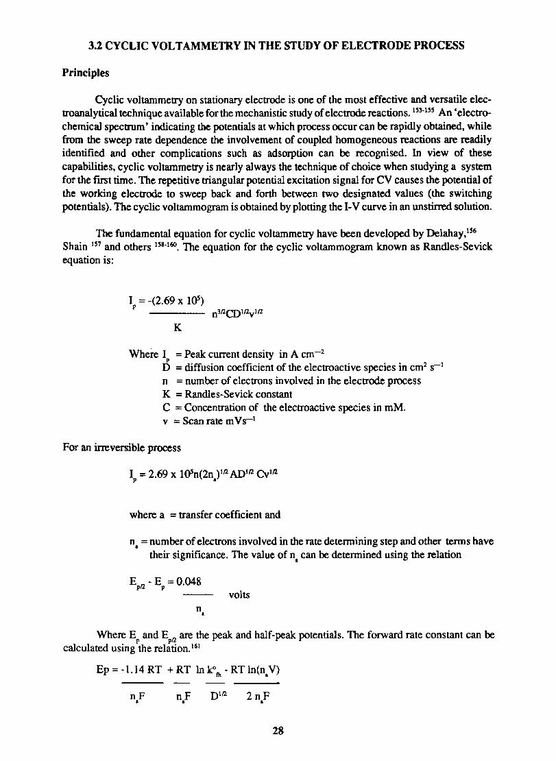
Cyclic voltammetry on stationary electrode is one of the most effective and versatile electroanalytical technique available for the mechanistic study of electrode reactions. m·IS!i An 'electrochemical spectrum' indicating the potentials at which process occur can be rapidly obtained, while from the sweep rate dependence the involvement of coupled homogeneous reactions are readily identified and other complications such as adsorption can be recognised. In view of these capabilities, cyclic voltammetry is nearly always the technique of choice when studying a system for the fmt time. The repetitive triangular potential excitation signal for CV causes the potential of the working electrode to sweep back and forth between two designated values (the switching potentials). The cyclic voltammogram is obtained by plotting the I-V curve in an unstirred solution.
The fundamental equation for cyclic voltammetry have been developed by Delahay,1S6 Shain 1!i7 and others 1S8-160. The equation for the cyclic voltammogram known as Randles-Sevick equation is:
Jp = -(2.69 x 10⁵) n3flCO I/ZvIlZ
K
Where J = Peak: current density in A cm-2 p
D = diffusion coefficient of the electroactive species in cm2 S-I n = number of electrons involved in the electrode process K = Randles-Sevick constant C = Concentration of the electroactive species in mM. v = Scan rate m VS-I
For an irreversible process
J = 2.69 x I05n(2n )Ifl ADlfl Cvlfl p •
where a = transfer coefficient and
n. = number of electrons involved in the rate detennining step and other tenns have their significance. The value of n. can be determined using the relation
E - E =0.048 pfl p volts
n •
Where E and E " are the peak: and half-peak: potentials. The forward rate constant can be P PI'"
calculated using the relation. 161
Ep = -1.14 RT + RT 10 le> fh - RT InCn.V)
nF nF 2nF • • •
28
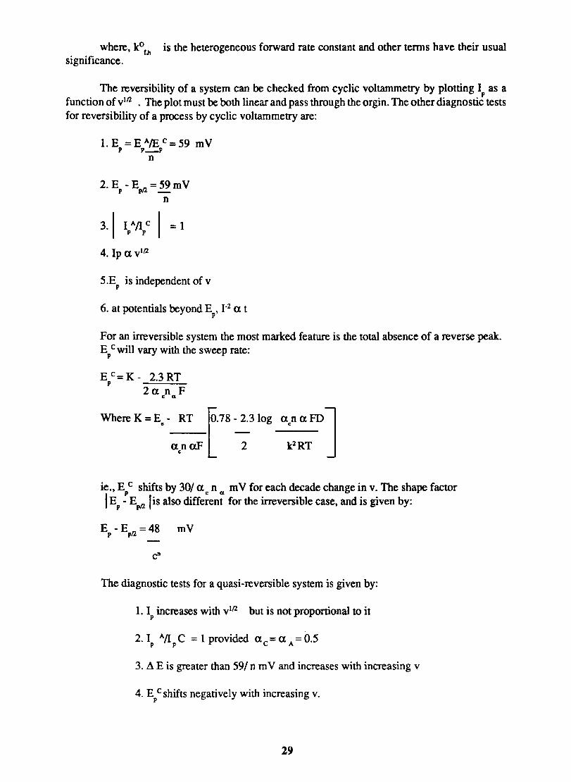
where, kOr.h is the heterogeneous forward rate constant and other tenns have their usual significance.
The reversibility of a system can be checked from cyclic voltammetry by plotting Jp as a function of vln . The plot must be both linear and pass through the orgin. The other diagnostic tests for reversibility of a process by cyclic voltammetry are:
1. E = E AlE C = 59 m V p p...:..-p
n
2. E - E n = 59 m V p p -
n
4. Ip a vln
5.E is independent of v p
6. at potentials beyond E , }-2 a t p
For an irreversible system the most marked feature is the total absence of a reverse peak. Ep C will vary with the sweep rate:
2a n F c Cl
Where K = E" - RT L.78 -2.3 log
anaF 2 c
acn CXFDJ k2 RT
ie., E C shifts by 301 a n mV for each decade change in v. The shape factor
I p c Cl
Ep - Epnlis also different for the irreversible case, and is given by:
E - E fl =48 mV p p
c"
The diagnostic tests for a quasi-reversible system is given by:
1. I increases with V1fl but is not proportional to it p
3. !!J. E is greater than 59/ n m V and increases with increasing v
4. E Cshifts negatively with increasing v. p
29
Cyclic voltammetry is probably the most powerful tool available for investigating coupled chemical reactions. In the case of a ce mechanism (Y~ 0; 0 + ne- ~ R) if the electron transfer is reversible and the chemical step is very slow. the current will be purely kinetically controlled and therefore no peaks will appear in the cyclic voltammogram. Instead, a simple steady state type wave will be obtained.
The diagnostic tests for CE mechanism are:
1. I C /v l !2 decreases as v increases p
2. I All E increases with v and is always greater than or equal to unity. p p
kl For the ec reaction (0 + ne- '" .... R; R.... >- Y) and if the electron transfer is totally
k irreversible, the following diagnostic tests can be applied to the system.
1. I All C is less than one but tends to unity as v is increased. p p
2. I C/Vlfl. decreases slightly with increasing v p .
3. E C is positive of the value for the reversible case p
4. E C shifts negatively with increasing v. p
Similarly cyclic voltammetty can be utilized for diagnosing catalytic reactions, ece reaction, and also surface process such as adsorption, deposition and passivation. Cyclic voltammetty is the principal technique used to determine the thermodynamic parameters of polymer films fonned on an electrode162 and it is the most extensively used technique to characterize the electroactiviity of monomolecular and multimolecular layers of redox species. l63
30
3.3 EXPERIMENTAL PROCEDURE
3.3.1. Chemicals
The metal phthalocyanines used were prepared and purified as described in section 2.1
All chemicals used were of guaranteed purity. The complexes of iron were prepared by mixing stoichiometric amounts of ferrous sulphate with the corresponding ligands. The solutions were prepared in doubly distilled water.
3.3.2 Pretreatment of platinum electrode
The platinum electrode was immersed in strong dichromate-sulfuric acid 'cleaning solution' for several minutes, then rinsed with tap water and finally with distilled water. It removes grease and oil as well as many of the organic films prevalent in the oxidation of aromatic compounds and oxidizes the platinum surface strongly.l64 The electrode was then dipped in hot nitric acid to oxidatively destroy any further organic materials on the surface. After rinsing with distilled water the electrode was immersed in air-free O.lM perchloric acid and subjected to strong cathodic pretreatment by holding the notential at -20V vs SCE for 10 minutes, during which time hydrogen was vigorously evolved at the surface. The electrode was then washed with distilled water and applied the cathodic pretreatment by immersing the electrode for 10 min. in an acid solution containing an oxidant (Bromine water). The anodic current occuring between 0.0 and 0.5 V vs SCE was completely eliminated by treating with the oxidant. Finally chemical reduction was done by immersing the electrode in ferrous sulfate solution and then immersing in 12M HCI and washing with distilled water.
A cyclic voltammogram was obtained at the electrode at the beginning of each experiment to check the quality of the electrode and also to determine the cathodic and anodic limits.
3.3.3 Background current and cycling history
The background current which flows under a set of given experimental conditions in the absence of the electroacvtive material is determined before the start of a new experiment
In the electrochemical studies a platinum wire electrode oflenght 5mm or a platinum button electrode of area 5(mm)2 was used as the working electrode. An auxiliary electrode of a sheet of platinum of area (15mm x 15mm) and a saturated calomel reference electrode were employed. The solution was made air free by flushing with nitrogen for about 20 minutes and keeping a positive nitrogen atomsphere in the cell during the experiment
A conventional undivided cell (Fig.3.1) was used for the electrochemical experiments. The reference electrode was introduced through a luggin capillary whose tip was positioned close to the working electrode to minimise IR drop.
3.3.4 Procedure For Setting The m Compensation 1'5
The method involves pulsing the working electrode in potential regions where no faradaic process occurs, while moitoring the current vs time behaviour. The ability of the working electrode to follow an applied square-wave signal is a function of the solution resistance, R between the working and reference electrodes, and of the double-layer capacitance, C of the working electrode.
31
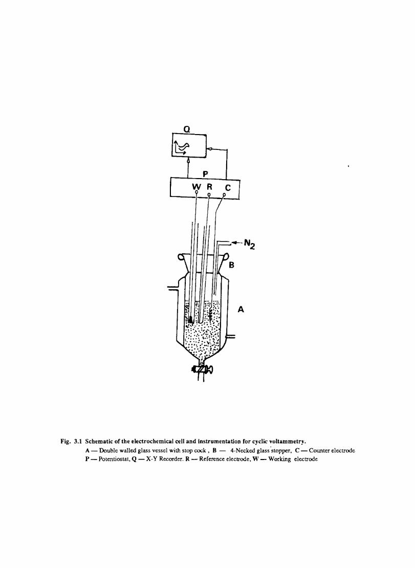
Q
A
Fig. 3.1 Schematic of the electrochemical cell and instrumentation for cyclic voltammetry. A - Double walled glass vessel with stop cock, 8 - 4-Necked glass 'stopper, C - Counter electrode P - Potentiostat, Q - X-Y Recorder. R - Reference electrode, W - Working electrode
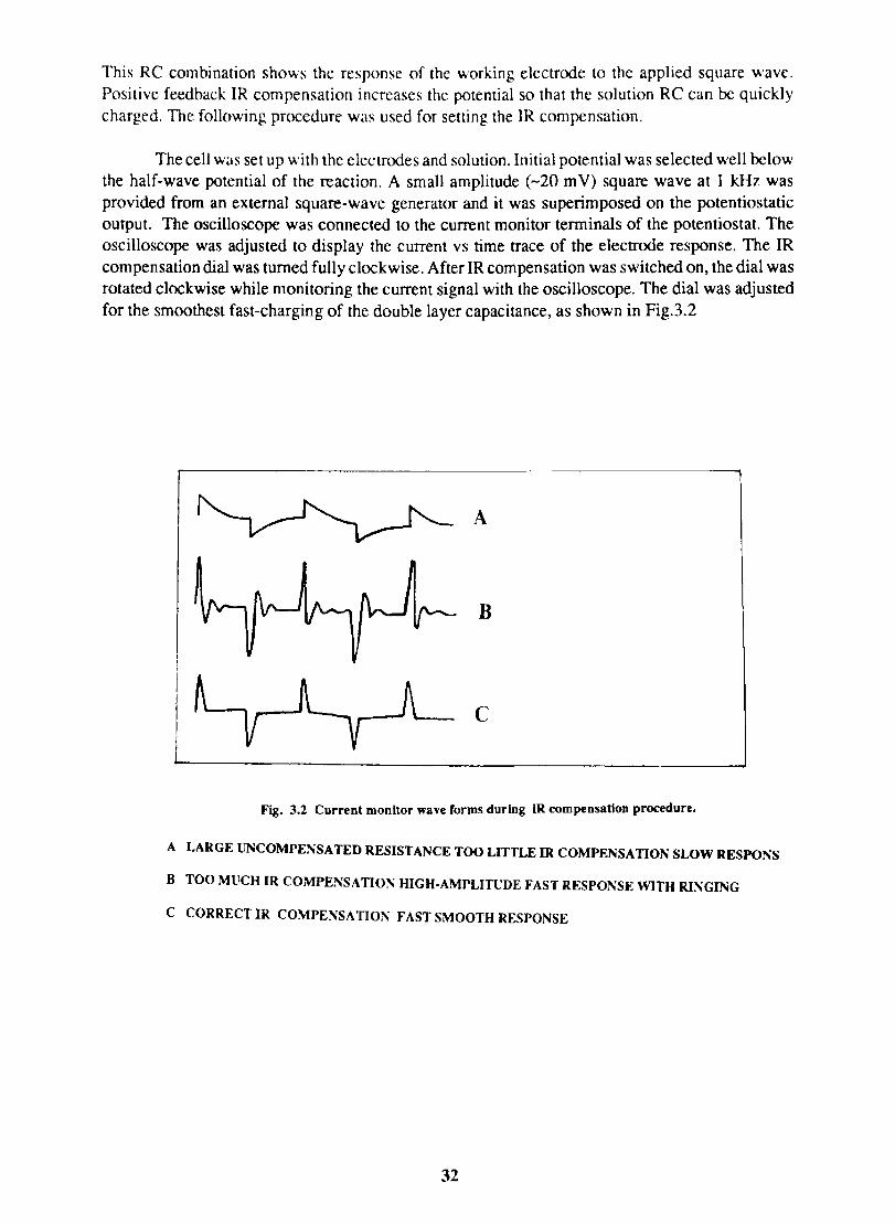
This RC combination shows the response of the working electrode to the applied square wave. Positive feedback IR compensation increases the potential so that the solution RC can be quickly charged. The following procedure was used for setting the IR compensation.
The cell was set up with the electrodes and solution. Initial potential was selected well below the half-wave potential of the reaction. A small amplitude (-20 mY) square wave at 1 kRz was provided from an external square-wave generator and it was superimposed on the potentiostatic output. The oscilloscope was connected to the current monitor terminals of the potentiostat. The oscilloscope was adjusted to display the current vs time trace of the electrode response. The IR compensation dial was turned fully clockwise. After IR compensation was switched on, the dial was rotated clockwise while monitoring the current signal with the oscilloscope. The dial was adjusted for the smoothest fast-charging of the double layer capacitance, as shown in Fig.3.2
A
B
c
Fig. 3.2 Current monitor wave forms during IR compensation procedure.
A LARGE IJNCOMPENSATED RESISTANCE TOO LITTLE IR COMPENSATION SLOW RESPONS
B TOO MUCH IR COMPENSATIO~ HIGH-AMPLITUDE FAST RESPO~SE WITH RI~GING
C CORRECT IR COMPENSATION FAST SMOOTH RESPONSE
32
IR compensation adjustments are critical in the sense that any change in the system (sensitivity. cell geometry, supporting electrolyte, etc.) will change the amount of compensation required.
3.3.5 Plasma Treatment
The plasma was generated in a glass tube by capacitive coupling as described in section. The electrode was mounted in the closed tube and placed close to the plasma source and rotated periodically to make the treatment uniform. The atmosphere in the tube was air at a pressure of -30 torr.
3.3.6 Results
Electron transfer process mediated by electrodes modified with CoPc, FePc, ZnPc, CuPc and NiPc were carried out by cyclic voltammetry.
The cyclic voltammograms recorded for the supporting electrolyte in bare Pt and MPc coated Pt are shown in Fig.3.3 In deaerated O.lM KN0
3 solution CoPc. NiPc and ZnPc show a flat
background response from O.OV to -0.8V vs SCE. The cathodic peak onset occurs at -O.8V. A positive scan from O.QV shows a quasi-reversible process at O.3V in the case of ZnPc & NiPc and for CoPc a peak is observed at 0.79V.The quasi-reversible nature confmned nature confmned from the i vs Vlfl plot The value of i increases with Vlfl but is not directly proportional to it. It is also p p
found thet AB is greater that 59/n m V and increases with increasing scan rate.
The background current is only a small fraction of the faradaic current produced by added electroactive species in the 4-1 OmM concentration range.
Fig. 3.4 shows the cyclic voltammetric responses of different redox couples at a Pt electrode. The potentials at which electron transfer take place in these compounds lie within the range selected to study the behaviour of phthalocyanine electrodes. All these systems give characteristic well defined redox peaks at a Pt electrode. The cyclicvoltamemetric characteristics for the oxidation and reduction of these compounds at Pt electrode are summarised in Table. 1
Fig. 3.4 shows the cyclic voltammograms of the different redox couples at CoPc/Pt electrode. Table IT lists the potential at which the redox couples undergone electron transfer. Fig. 3.5 shows the scan rate dependence of the anodic peak current at the CoPc electrode for ferrocyanide in 0.1 M KN03 medium. The linear variation of peak current with square root of the scan rate rules out any involvement of the adsorption of electroactive species on the electrode. AE is close to 59 m V and
p
the peak: is asymmetric. These results show that diffusion controlled reversible charge transfer of redox species is possible at these electrodes. The electrode process occurring may be on the MPc surface or on the metal surface by the penetration of the solution through pin holes or channels that may be present on the fIlm. Hence it is necessary to confmn the site of the heterogeneous charge transfer.
Evidences for the occurence of charge transfer at MPc Surface
1. The diffusion current at CoPe has the same magnitude (within experimental error) as that on a bare electrode (Fig 3.5) 2. Under identical conditions the voltammogram at CuPc (Fig. 3.7 ) is considerably distorted and show only small peak currents. This behaviour is in agreement with the observation of other authors·l66
33
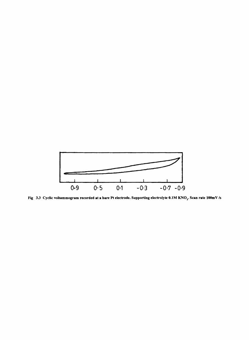
o·g 0·5 0·1 -0·3 -0·7 -O-g Fig 3.3 CycUc \,oltammogram recorded at a bare Pt electrode. Supporting electrolyte O.lM KN03• Scan rate lOOmV Is
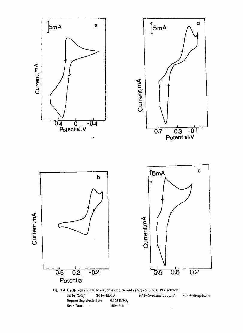
« E
a
04 0 -0.4 Potential, V
0.2 Potential
;
-0.2
b
15mA
0·3 -0·1 Potential, v
c
d
Fig. 3.4 Cyclic Yoltammetric response of different redox couples at Pt electrode
(a) Fe(CN)64
- (b) Fe-EDTA (c) Fe(o-phenanthrolinc) (d) Hydroqumonc
Supporting electrolyte O.lM KN03
Scan Rate lOOmV/s
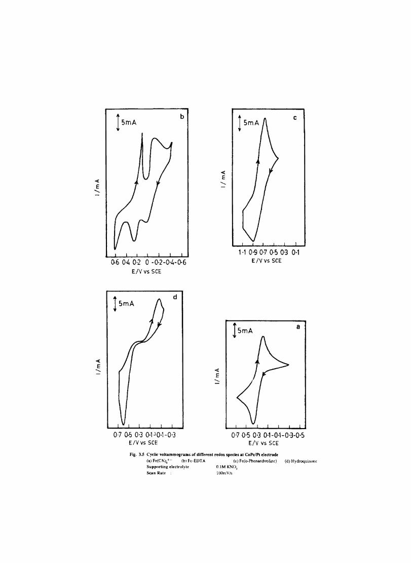
lsmA b
()'6 0-4 0-2 0 -0-2-0'4-0-6 ElY vs SCE
lsmA d
0-7 0-5 0·3 0·1 JO-l-0·3 ElY vs SCE
c
1-1 0-9 0-7 O-~ 0-3 0-1 EIV vs SCE
J5mA a
0'70-5 0·3 0-1-0-1-0-3-0·5 EIV vs SCE
Fig. 3.5 Cyclic voltammogram, of dlrr • ...,n( redox sp.cles at CoPcJPt .leclrod.
(a) Fe(C/';J:- (b) Fe-ElnA (c) Fe(o.Phenan\hrohnc) (d) Hydroquimmc Supp()r1in~ d.clrol~·t. O.lM KNO,
Saln Rate lOOmV!s
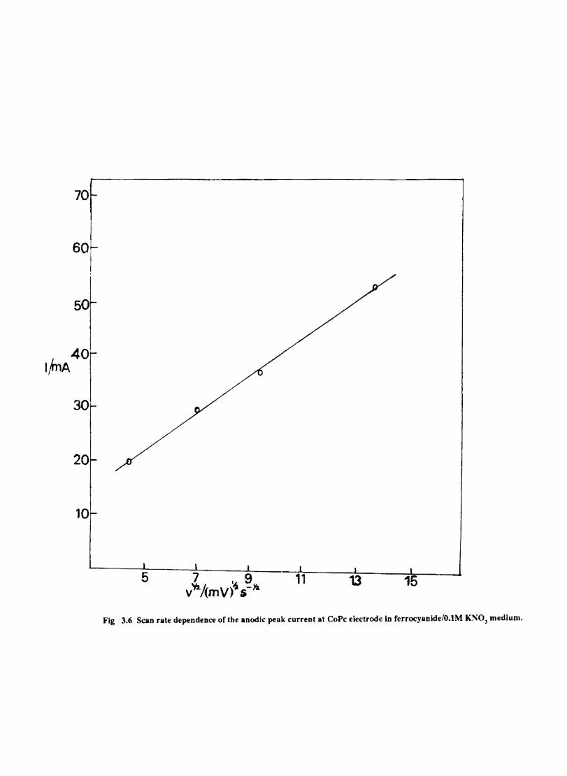
70
60
50
20
10
11 13 15
Fig 3.6 Scan rate dependence of the anodic peak current at CoPc electrode in ferrocyanide/O.IM KSO) medium.
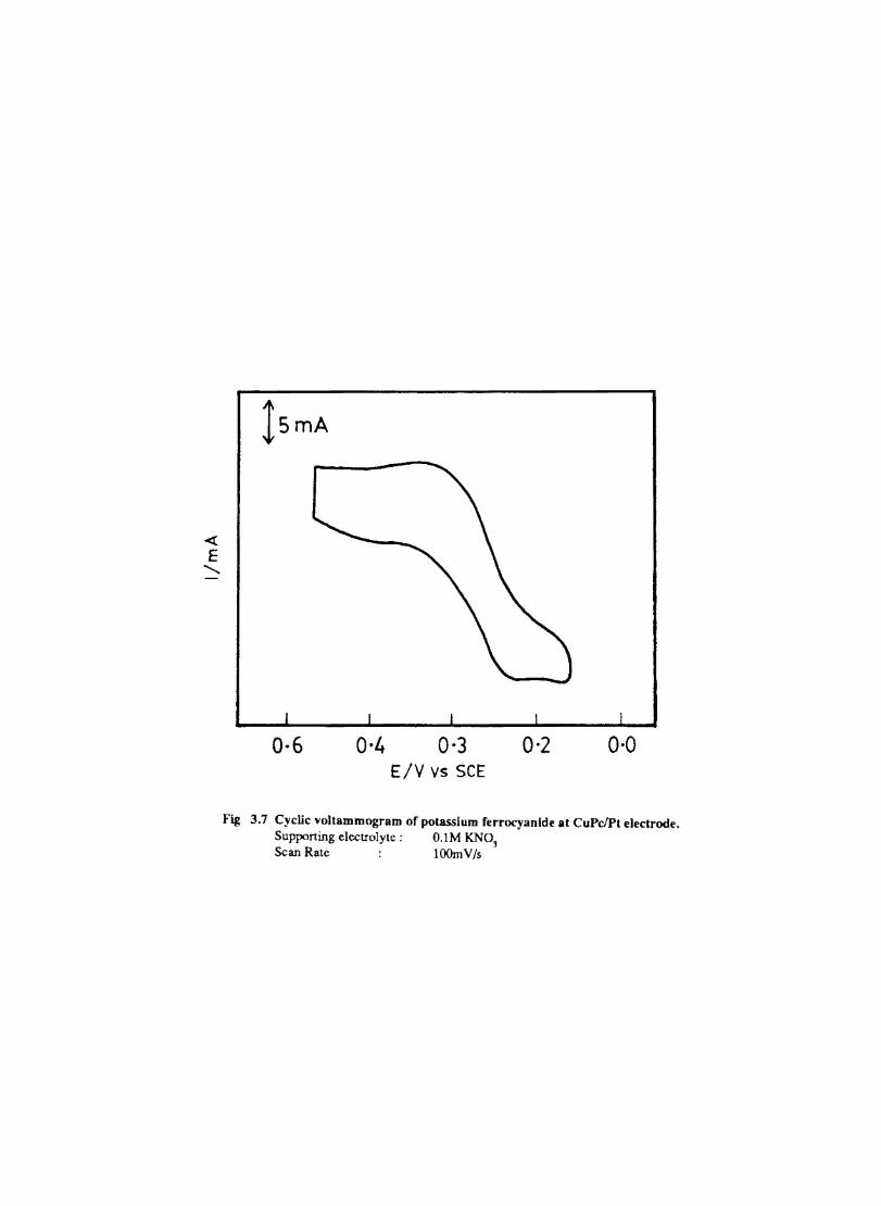
ls mA
0-6 0·4 0·3 0·2 0·0 E/V vs SCE
Fig 3.7 Cyclic voltammogram of potassium ferrocyanlde at CuPc!Pt electrode. Supporting electrolyte; O.lM KNO] Scan Rate lOOm V /s
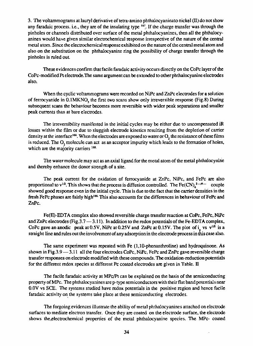
3. The voltammograms at lauryl derivative of tetra·amino phthalocyaninato nickel (ll) do not show any faradaic process. i.e., they are of the insulating type 16~. If the charge transfer was through the pinholes or channels distributed over surface of the metal phthalocyanines, then all the phthalocy· anines would have given similar electrochemical response irrespective of the nature of the central metal atom. Since the electrochemical response exhibited on the nature of the central metal atom and also on the substitution on the phthalocyanine ring the possibility of charge transfer through the pinholes is ruled out
These evidences confmn that facile faradaic activity occurs directly on the CoPc layer of the CoPc·modified Pt electrode.The same argument can be extended to other phthalocyanine electrodes also.
When the cyclic voltammograms were recorded on NiPc and ZnPc electrodes for a solution of ferrocyanide in O.lMKN0
3 the first two scans show only irreversible response (Fig.8) During
subsequent scans the behaviour becomes more reversible with wider peak separations and smaller peak currents than at bare electrodes.
The irreversibility manifested in the initial cycles may be either due to uncompensated iR losses within the film or due to sluggish electrode kinetics resulting from the depletion of carrier density at the interfacel66
• When the electrodes are exposed to water or 02 the resistance of these films is reduced. The 02 molecule can act as an acceptor impurity which leads to the formation of holes, which are the majority carriers 168.
The water molecule may act as an axial ligand for the metal atom of the metal phthalocynine and thereby enhance the donor strength of a site.
The peak current for the oxidation of ferrocyanide at ZnPc, NiPc, and FePc are also proportional to Vlll. This shows that the process is diffusion controlled. The Fe(CN)t---14- couple showed good response even in the initial cycle. This is due to the fact that the carrier densities in the fresh FePc phases are fairly highl66
. This also accounts for the differences in behaviour of FePc and ZnPc.
Fe(ll)·EDTA complex also showed reversible charge transfer reaction at CoPc. FePc, NiPc and ZnPc electrodes (Fig. 3. 7 - 3.11). In addition to the redox poten tials of the Fe· EDTA complex, CoPc gave an anodic peak at O.5V, NiPc at O.25V and ZnPc at O.15V. The plot of i vs v1(J. is a
p
straight line and rules out the involvement of any adsorption in the electrode process in this case also.
The same experiment was repeated with Fe (l,10·phenanthroline) and hydroquinone. As shown in Fig.3.9 - 3.11 all the four electrodes CoPc, NiPc, FePc and ZnPc gave reversible charge transfer responses on electrode modified with these compounds. The oxidation-reduction potentials for the different redox species at different Pc coated electrodes are given in Table. IT
The facile faradaic activity at MPclPt can be explained on the basis of the semiconducting property ofMPc. The phthalocyanines are p-type semiconductors with their flat band potentials near O.OV vs SCE. The systems studied have redox potentials in the positive region and hence facile faradaic activity on. the systems take place at these semiconducting electrodes.
The forgoing evidences illustrate the ability of metal phthalocyanines attached on electrode surfaces to mediate electron transfer. Once they are coated on the electrode surface, the electrode shows the,electrochemical properties of the metal phthalocyanine species. The MPc- coated
34
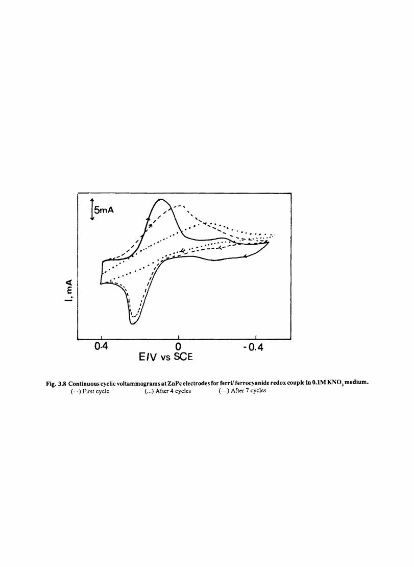
et E
Ism A
0.4
... • • •.•. • -_ . .; ~:;::-'----7
.k ":..-~--...( .' ,
o E/V VS SCE
- 0.4
Fig. 3.8 Continuous cyclic voltammograms at ZnPc electrodes for ferril ferrocyanide redox couple In O.lM Kl'"03 medium. (- -) First cycle ( ... ) After 4 cycles (-) After 7 cycles
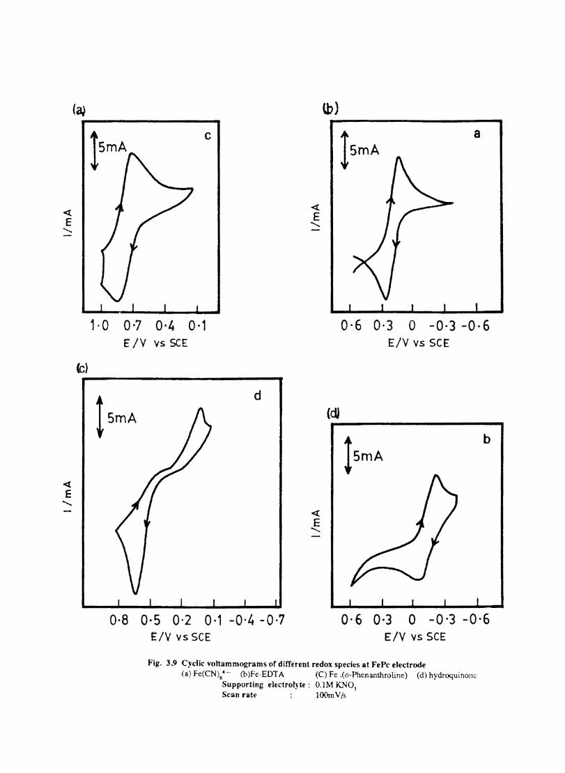
« E "
(c)
c
1· 0 0·7 0·4 0·1 ElY vS SCE
« E "
(b)
15mA
a
0-6 0·3 0 -0·3 -0·6 ElY vs SCE
t5mA
d (dJ
15mA
b
0·8 0·5 0·2 0·1 -0-4 -0-7 ElY vs SCE
<t: E "
0-6 0-3 0 -0'3 -0,6 ElY vs SCE
Fig. 3.9 Cyclic voltammograms of different redox species at FePc electrode (a) Fc(CN\4 - (b)Fe-EDT A (C) Fe .(o-Phcnanthroline) (d) hydroquinonc
Supporting electrollte: O.lM KNO] Scan rate : lOOm V /s
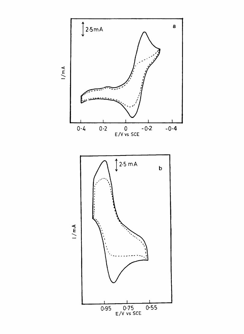
120smA
0-4 0·2 0 -0·2 ElY vs SCE
\
I ... "'111 ______ .... -- ........ ,
, .'
0·95 0·75 0-55 ElY vs SCE
a
-0·4
b
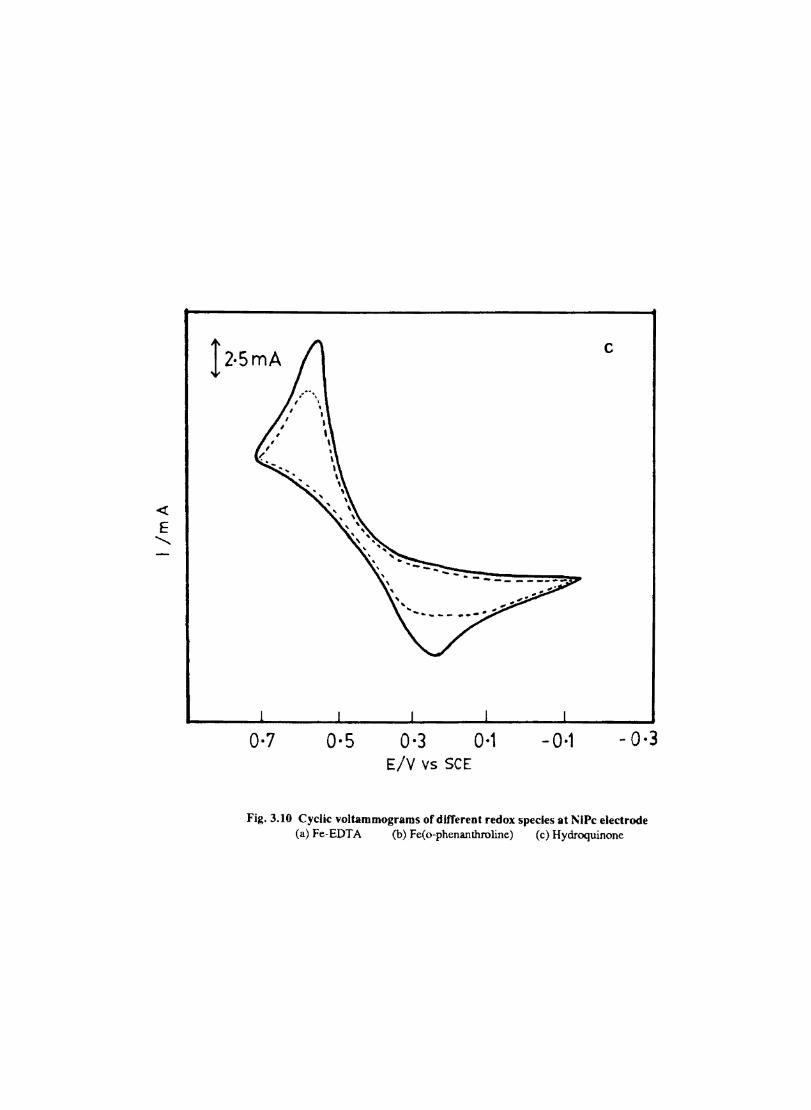
12.smA c
0·7 0·5 0·3 0·1 - 0·1 - 0·3 E/v vs SCE
Fig. 3.10 Cyclic voltammograms of different redox species at ~IPc electrode (a) Fe-EDTA (b) Fe(o-phenanthroline) (c) Hydroquinone
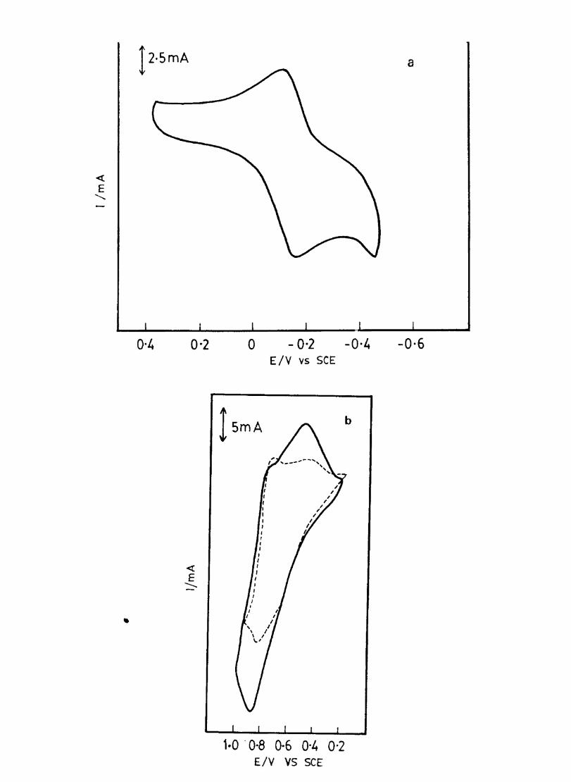
0·4 0'2
« E
---
o
l smA
- 0·2 ElY vs SCE
-0,4
b
1·0 . 0·8 0·6 0'4 0'2 ElY VS SCE
a
-0·6
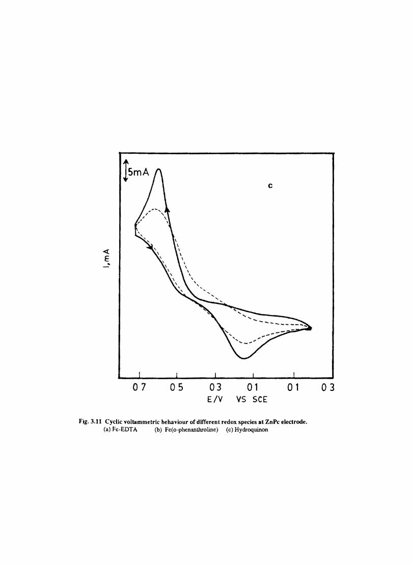
<! E ..
07 05 03 01 01 EIV VS SCE
Fig.3.11 Cyclic voltammetrlc behaviour of different redox species at ZnPc electrode. (a) Fe-EDTA (b) Fe(o-phenanthroline) (c) Hydroquinon
03
electrodes withstand multiple potential cycling and hence are durable as modified electrodes.
3.3.7 Electrochemical behaviour of rf plasma treated metal phthalocyanine electodes
The metal phthalocyanines are treated with rf-plasma in order to create more active sites on the phthalocyanine surface. Exposure of materials to plasma gives films of increased cohesive strength. adhesion and crosslinking.
Fig. 3.12 shows the cyclic voltammetric behaviour of plasma treated CoPc electrode towards various redox species such as potassium ferrocyanide. hydroquinone. Fe-EDTA. Fe(o -Phenanthroline). The treatment of phthalocyanine with plasma evidently lowers the onset potential for the electron transfer process. The peak currents are increased substantially. The diffusional behaviour of the electrode process confirmed by the linear dependence of i on the square root of the scan rate
p (Fig. 3.13). This also suggests that adsorption does not complicate the electrode process.
The ZnPc electrode which fails to mediate the reversible redox process for ferrocyanide in the initial cycles gives characteristic redox behaviour in the first cycle itself. if it is exposed to rf plasma (Fig. 3. 14a) This may be due to the increase in activity and conductivity of ZnPc fIlm as a results of exposure of ZnPc ftlm to plasma.
The CuPc electrode which gives only distorted peaks for the redox process involving ferrocyanide/ferricyanide couple shows better electrochemical response when it is cycled in a 4mM solution of Fe(CN)4--
6 after treatment with rfplasma (Fig. 3.14.b).
The plasma treatment is thus seen to be an efficient method for increasing the activity of electnxles modified with MPc.
3.3.8 Reduction of DiOxygen at MPc Modified Electrodes
A good quantum of research has already been expended on the electrocatalysis of dioxygen reduction because of its use in fuel cells The electrocatalytic behaviour of Mpcs supported on carbon electrodes were studied because of the chemical diversity of carbon electrodes and the possible interaction of extended TI-electron system of phthalocyanine molecule with that of graphite. The type of mechanism for dioxygen reduction at graphite and platinum differ. We have examined the 02 reduction at platinum electrode coated with Mpc.
The elecnocatalytic activity of MPc coated electrodes are found to be stable in basic media than in neutral or acid media For a surface to be a good catalyst for the reduction of 02 it must not only facilitate the transfer of electrons but also actively decompose ~02 170. The over voltage for the reduction of O2 in alkaline medium is lower because an adsorbed oxygen film may be better maintained in such solutions and the electrode surface may act as a more effective ~02 -decomposion catalyst. Hence the electrocatalysis of q reduction by the MPcs was studiedonly in alkaline medium.
The 02 reduction wave was conftrrned from the observation that the intensity of th~ peak decreases and then completely disappears on displacing 02 from the medium using N2 gas.
Fig.3.16a shows the 02 reduction wave at a platinum electrode. At this electrode only an irreversible peak of low intensity occurs at-o.6V. The response of 02 at a CoPc/Pt electrode is shown in Fig.
35
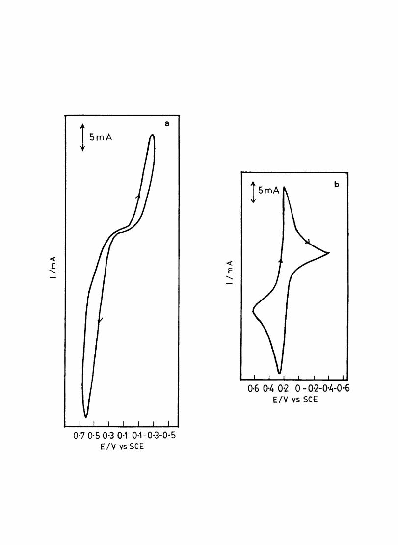
« E
"'"
l smA
a
0'7 0·50·3 0,1-0·1-0'3-0·5 ElY vs SCE
« E
"'"
b
0·6 0·4 0-2 0 - 0·2-cr4-0·6 ElY vs SCE
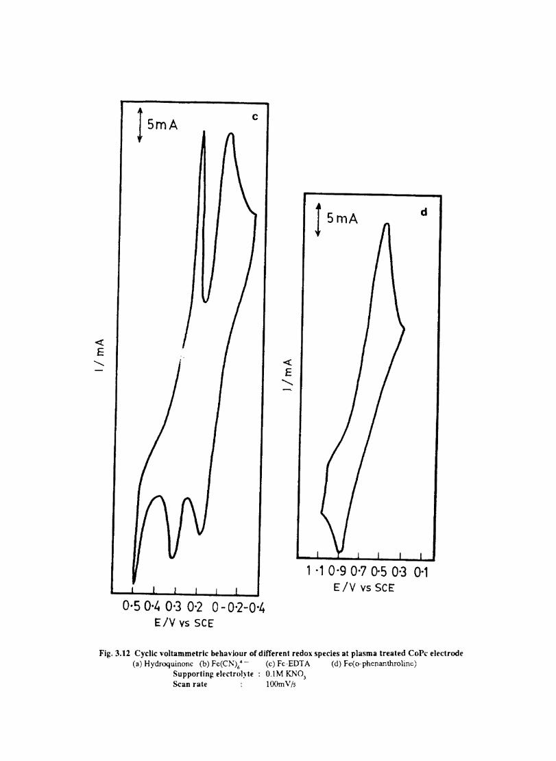
« E '-
lsmA c
0·5 0·4 0·3 0·2 0 - 0·2-0·4 E/V vs SCE
« E ,
d
1 ·1 O·g 0·7 0-5 0·3 0·1 E/V vs SCE
Fig. 3.12 Cyclic voltammetrlc behaviour of different redox species at plasma treated CoPe electrode (a) Hydroquinonc (b) Fe(CN)6' - (c) Fc-EDT A (d) Fe(o-phcnanthrolinc) Supporting el('ctrol~"te : O.1M KNO) Scan rate lOOmV/s
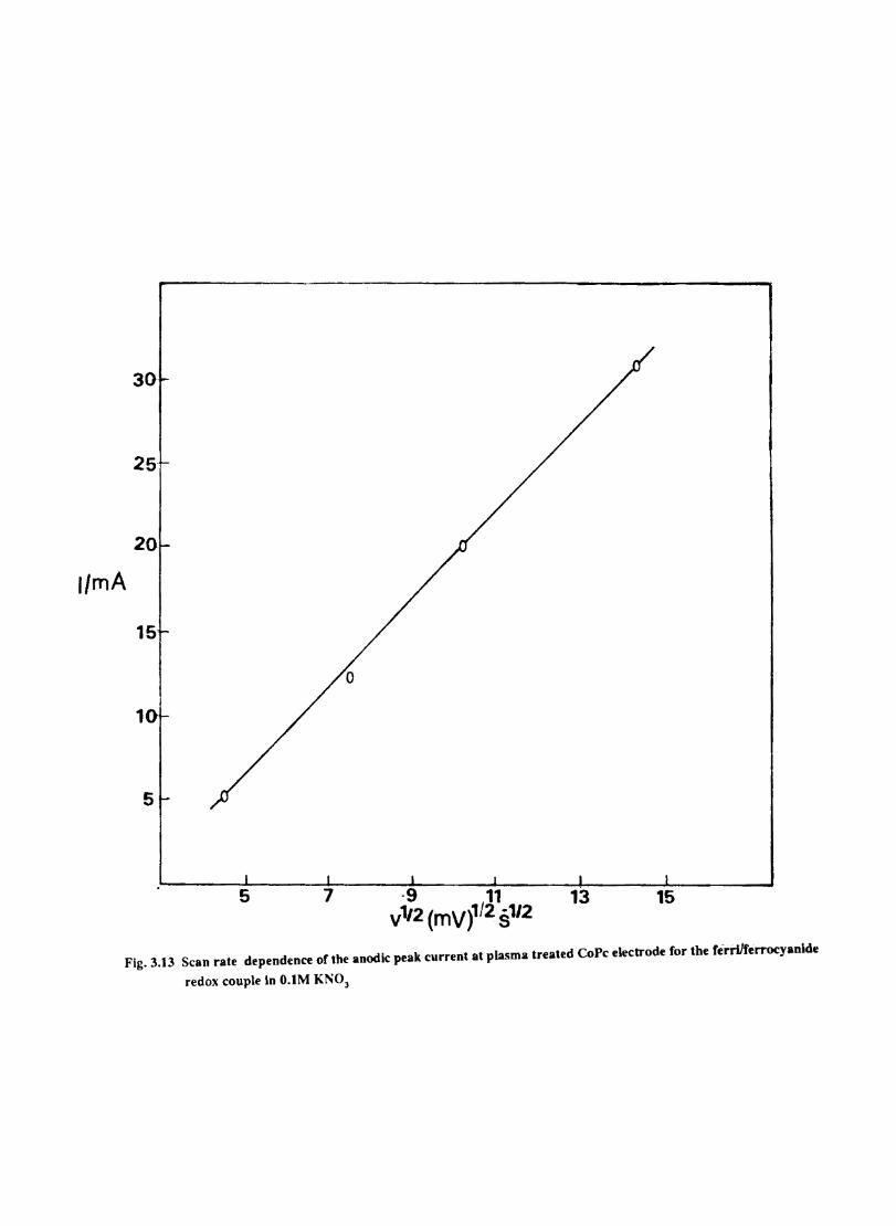
30
25
20
I/mA
15
10
5
5 7 ·9 11 v'1i2 (mv)1/2 81/2
13 15
Fig. 3.13 Scan rate dependence or tbe anodic peak current at pla.'ima treated CoPc electrode for the ferrilferroc:yan.de
redox couple In O.IM KNOJ
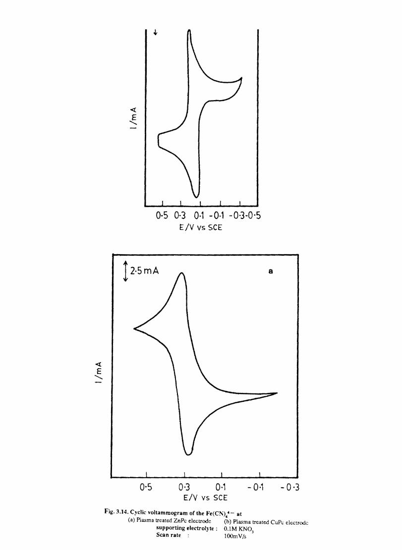
« E
.........
« E ........
0·5 0·3 0·1 - 0·1 -0·3-0,5 E/v vs SCE
!2.smA
0·5 0·3 0·' - 0·1 E/V vs SCE
a
-0,3
Fig. 3.]4. Cyclic voltammogram of the Fe(CN),· - at (a) Plasma treated ZnPc electrode (b) Plasma treated CuPc electrode
supporting electrol~·te: O.lM KNO) Scan rate : lOOmV/s
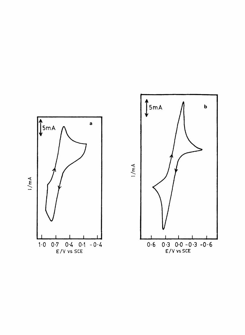
< E
........
lsmA a
1-0 0·7 0'4 0·1 -0,4 ElY vs SCE
<{
E ........
b
0·6 0·3 0·0 -0·3 -0·6 ElY vs SCE
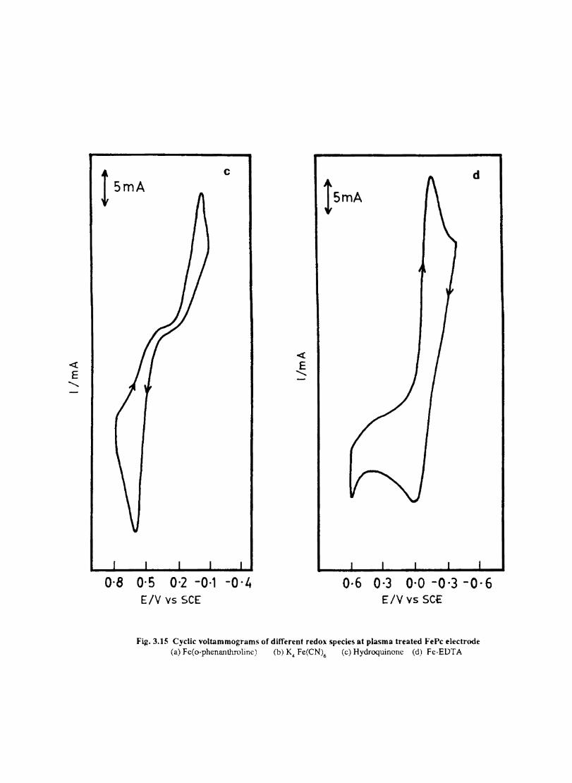
<t E "
t smA c
0-8 0-5 0-2 -0-1 -O-it ElY vs SCE
<t E "
d
0-6 0-3 0-0 -0-3 -0-6 ElY vs SCe
Fig. 3.15 Cyclic voltammograms of different redox species at plasma treated FePc electrode (a) Fc(o-phenanthrolinc) (b) K4 Fe(CN)6 Cc) Hydroquinonc Cd) Fe-EDTA
3.16b 02 is catalytically reduced at a potential ofO.4SV. The well resolved peak with enhanced peak current shows that CoPc exerts electrocatalytic activity for 02 reduction.
As shown in the Fig. 3.l6c FePc reduces dioxygen at a still lower positive potential. The enhanced peak current and the ability of FePc to reduce 02 at a lower potential suggest that FePc is more effective than CoPc.
Dioxygen is also electrocatalytically reduced at ZnPc and NiPc at 0.45 and 0.40 respectively. (Fig. 3.16c - 3.16d). This is not in agreement with the reports of Faulkner et al 117 They have reported that 02 reduction was inhibited on ZnPc and FePc thin fil~ (100-4000 A) when these were deposited on a gold fIlm overlaid on glass substrate.
The catalytic activity of metal phthalocyanine follows the order: FePc>CoPc>CuPc>NiPc>ZnPc. This order can be correlated with the electrooxidation potentials of these metal phthalocyanines as follows. The MPe molecule gets oxidised by donating an electron to the platinum working electrode according to the scheme:
MPc +Pt ---;> (M.Pet + e- (Pt) (1)
When an 02 molecule gets reduced at the MPc, the MPc will donate an electron to the oxygen molecule according to the scheme:
> (M.Pe) + 02 - (2)
Reduction schemes (1) and (2) are analogous and each involves the donation of an electron by MPc to either Pt or 02' It is clear that the ftrst oxidation potential of MPc can be correlated with the catalytic activity for 02 reduction.
3.3.9 Electrocatalytic reduction of dioxygen by plasma-treated cobalt phthalocyanine
As a result of rf-plasma treatment, the electrocatalytic activity ofMPc electrodes is increased. Fig. shows that 02 is reduced at -0.3V on CoPc electrode. The peak current is also enhanced. Other MPcs also show increase in electrocatalytic activity after exposing to plasma.
The heterogenous rate constant for 02 reduction at MPc electrodes and rf-plasma treated with MPc electrodes are given in Table n
36
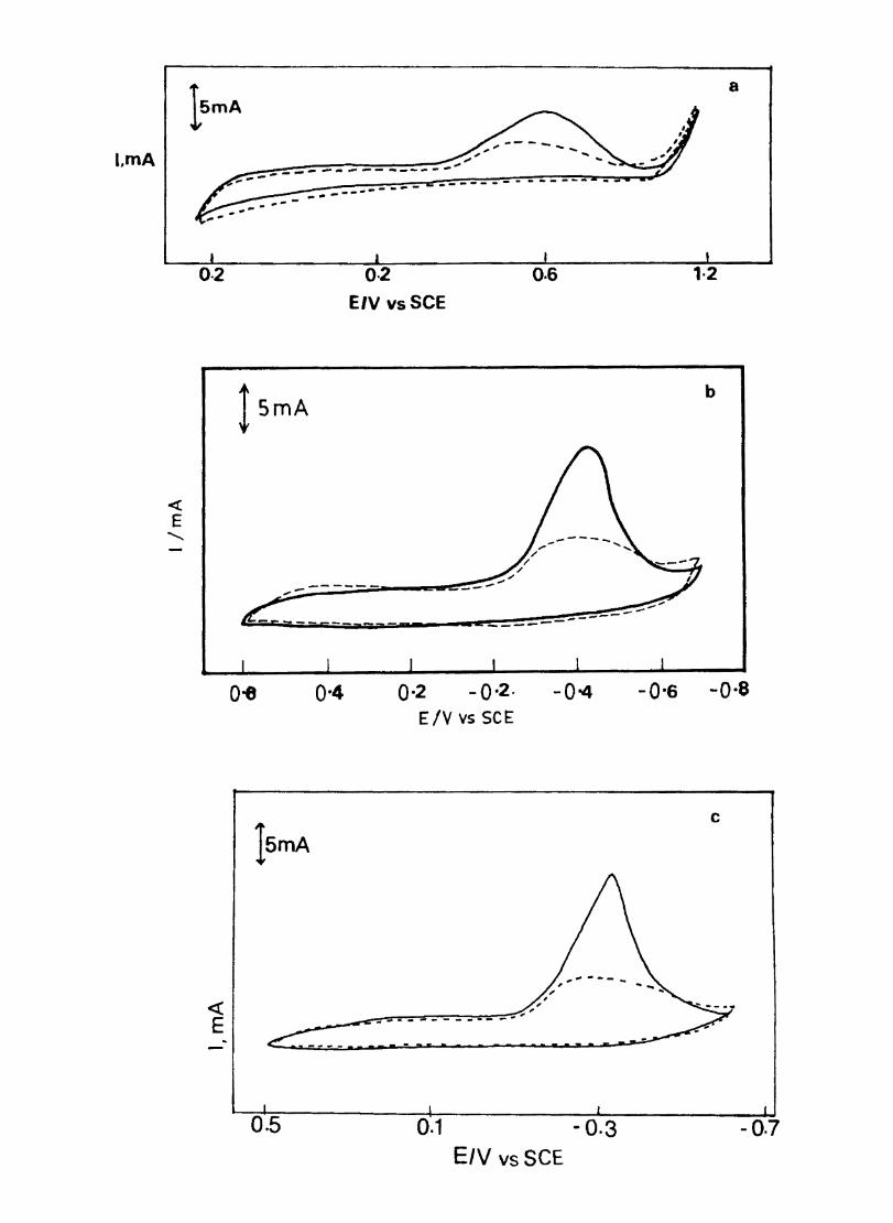
LmA
<t E
..........
0-2
« E
---------------
!5mA
----- -------- ... _----- -
0·2
E/V vsSCE
..-'"
0·6
/ /
/
". ,..-----
------- -- - - ------
0-8 0·4 0·2 - 0 ·2. - 0-4 E IV vs SCE
15mA
... _-------_ .. "
a
1·2
b
---
-0·6 -0·8
c
0.5 0.1 - 0.3 -0.7 E/V vs SCE
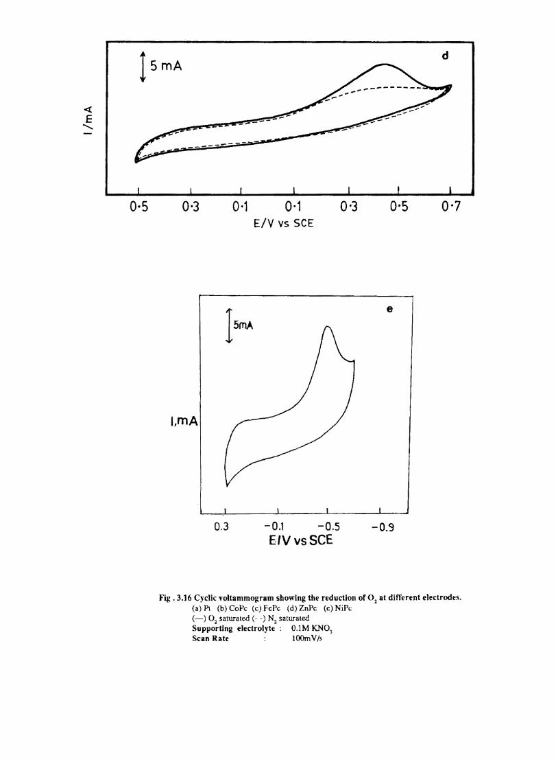
<t: E
........
l smA d
0·5
------
0·3 0-1
I~
l,mA
0.3
0-1 ElY vs SCE
-0.1 -0.5 EIVvsSCE
0-3 0-5 0-7
e
-o.Cj
Fig. 3.16 C~'clic voltammogram showing the reduction of 0: at different electrodes. (a) Pt (b) CoPe (c) FePc (d) ZnPc (e) NiPc (-) O~ saturated (- .) N2 saturated Supporting electrolyte: O.lM KNO, Scan Rate lOOmV/~
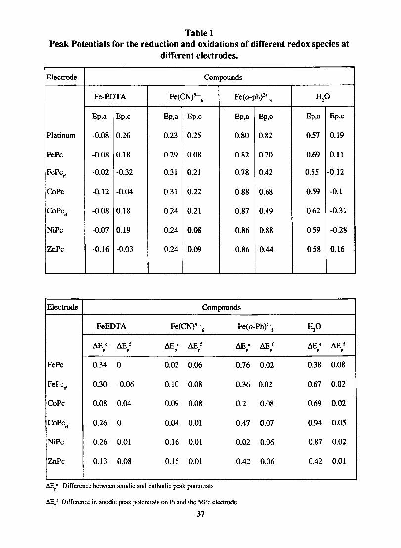
Table I Peak Potentials for the reduction and oxidations of different redox species at
different electrodes.
Electrode Compounds
Fe-EDTA Fe(CN)3-6
Fe(o-ph)2+ 3
Ep,a Ep,c Ep,a Ep,c Ep,a Ep,c
Platinum -0.08 0.26 0.23 0.25 0.80 0.82
FePe -0.08 0.18 0.29 0.08 0.82 0.70
FePcrf -0.02 -0.32 0.31 0.21 0.78 0.42
CoPe -0.12 -0.04 0.31 0.22 0.88 0.68
COPCd -0.08 0.18 0.24 0.21 0.87 0.49
NiPe -0.07 0.19 0.24 0.08 0.86 0.88
ZnPe -0.16 -0.03 0.24 0.09 0.86 0.44
Electrode Compounds
FeEDTA Fe (CN)3-6 Fe(o-Ph)2\
L\E e L\E f L\E c ~f L1E e P P P P P
FePc 0.34 0 0.02 0.06 0.76
FeP':tf 0.30 -0.06 0.10 0.08 0.36
CoPe 0.08 0.04 0.09 0.08 0.2
CoPed 0.26 0 0.04 0.01 0.47
NiPc 0.26 0.01 0.16 0.01 0.02
ZnPe 0.13 0.08 0.15 0.01 0.42
IlEp' Difference between anodic and cathodic peak polentials
1lE/ Difference in anodic peak potentials on Pt and the MPc electrode
37
L1E f P
0.02
0.02
0.08
0.07
0.06
0.06
~o
Ep,a Ep,e
0.57 0.19
0.69 0.11
0.55 -0.12
0.59 -0.1
0.62 -0.31
0.59 -0.28
0.58 0.16
~O
L\E C ~f P P
0.38 0.08
0.67 0.02
0.69 0.02
0.94 0.05
0.87 0.02
0.42 0.01
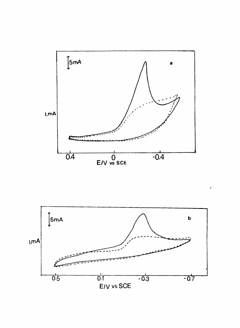
l,mA
..
0.4
0·5
o E/V vs SCE
---- -.- - --
0·1 - 0.3 E/V vs SCE
-0.4
b
-0.7
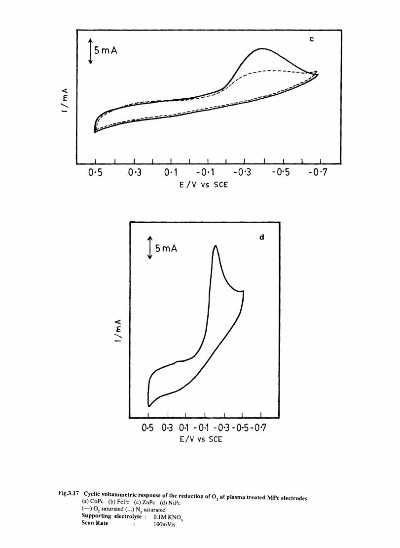
lsmA
0-5 0-3 0-1 - 0-1 E IV vS SCE
l smA
d
0·5 0·3 0·1 - 0·1 -0·3 -0,5 -0-7 E/V vs SCE
Fig.3.]7 Cyclic voltammetric response of the reduction of 02 at plasma treated MPc electrodes (a) CoPe (b) FePe (c) ZnPe (d) NiP, (-) 02 saturated (. .. ) N2 saturated Supporting electrolyte: O.lM KN03
Scan Rate l00mV/s
c
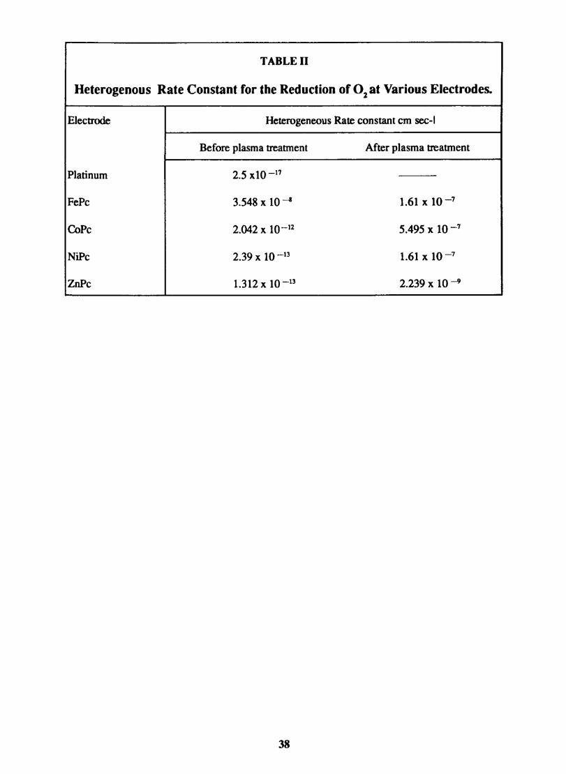
TABLE 11
Heterogenous Rate Constant for the Reduction of 02 at Various Electrodes.
Electrode Heterogeneous Rate constant em sec-I
Before plasma treatment After plasma treatment
Platinum 2.5 dO -17
FePc 3.548 x 1O~ 1.61 x 10⁻⁷
CoPe 2.042 x 10⁻¹² 5.495 X 10⁻⁷
NiPc 2.39 x 10⁻¹³ 1.61 x 10⁻⁷
ZnPc 1.312 x 10 -13 2.239 X 10⁻⁹
38
CHAPTER IV Electrical conductivity of metal phthalocyanines
4.1 Introduction
Eleyand Vananyan 170,171 were the fIrst l:oobserve semiconductivity in phthalocyanines (Pc). With intrinsic semiconductivity the current carriers are moble TI-electrons. The temperature dependence of the conductivity follows the relation
o = 0 0 exp (-Ea/kT)
where ° = specific conductivity at temperature T in Scm -1
0 0 = specifIc conductivity at infinite temperature Ea = activation energy and R = gas constant
The electrical conductivity increases markedly with increasing presure at constant temperature and with increasing temperature at constant pressure 172.
Electrons are not exited to the conduction band, but rather they are trapped at impurity centres or crystal imperfection leaving positive holes.
Replacement of the two central hydrogen atoms by a metal atom has little effect upon the energy gap which lies between 1.5 to 1.7 eV and is sensitive to the atmosphere surrounding the sample. The electrical conductivity of single crystals of metal free, copper, nickel and cobalt phthalocyanines were measured in the temperature range 50-3900 C. 173. The weighted mean values of the activation energies obtained were: 1.71 e V for the metal free, 1.60 e V for the cobalt and nickel and 1.64 eV for the copper substituted compounds.
The changes in the crystal habit at a - ~ phase transformation temperature of phthalocyanine, and appreciable anisotropy effects seriously impair the significance of the data which fail to take these fully into account 174
The resistivities of metal phthalocyanines are lower than that of metal free Pc CuPc shows the highest, and the Mg and Mn Pcs show the lowest resistivity values. The substitution may create a greater overlap between parallely aligned molecules; the copper atom acts as a bridge between nitrogen atoms on the molecules on the stack.
A considerable drop in resistivity as well as in activation energy is obtained upon changes in the peripheral part of the phthalocyanine ring system. m
A study of the effects of high pressure and the combined effects of high pressure and shear defonnation on the electrical conductivity ofMPcs show a sharp increase in conductivity at a critical pressure which depended on the electrode coating (Zn, Cu, or Ni). This increase is attributed to the inset of carrier injection. Under combined pressure and deformation the increase occurred at lower pressures also.
Electrical conductivity in Pes is associated with thermal and/or optical excitation of the mobile carriers of the phthalocyanine ring from the valence band containing highest molecular orbital to the conduction band made of lowest empty molecular orbitals.
39
Doping in MPcs
The effect of doping on the electrical and photoconductivity of molecular solids is well known. The electrical and photoconductivity of phthalocyanines is also found to be increased by the addition of dopants like o-chloraniI 177
• Based on the ESR measurements, this change is ascribed to the transfer of electron from Pc to the acceptor molecules in the dark, which produces holes in the Pc layer and converts o-chloranil to its anion radicals. When the Pc film is doped with2,4,7 trinitrofluorenone (TNF) 178 the carrier generation efficiency increases with increase in TNF concentration while its fluorescence is quenched. This is explained as resulting from the singlet exciton diffusion to the surface of the Pc at the dopant site, followed by the exciplex fonnation and its subsequent dissolution into charge carriers. The electronic process in molecular solids are complicated and their interpretation require molecular level consideration. 179.180 A study of the doping effect on the organic semiconductors gives a clue to the electronic processes such as charge carrier generation upon irradiation, the process being essential in photosynthesis and in solar energy conversion. 181
,
<;: The optoelectronic properties of materials can be modified by depositing phthalocyanines on these materials The photo induced charge injection from metal-free phthalocyanine has been used to photosensitize amorphous selenium in xerographic applications. The low intrinsic conductivity of phthalocyanines limits further exploitation of their optoelectronic properties. However by doping with iodine, the conductivity ofphthalocyanines can be markedly increased 114. 18S. Because of the high stability of 1
3- in polar environments, and its ability to accomodate itself into channels in one
dimensional lattices, iodine is an advantageous dopant for the oxidation of planar organic molecules. (Oxidation of an divalent metal complex would yield afJivalent metal ion if 1- were produced., but a nonintegral oxidation state would result if all metal sites in the material were crystallographically equivalent and if only ~ - were formed.) The utility of thHs synthetic approach is applied to phthalocyanines 186. This results in an extensive new class of highly conducting molecular solids. The oxidation of purified Fe Co,Ni, Cu, Zn" Pt phthalocyanines and metal-free phthalocyanine by iodine vapour or solutions results in dark colored solids with a range of stoichiometries 117 (equation 1), the exact composition obtained depending on the conditions.
~ MPc + x/2 I,. ~ (MPc) (I)~ (1)
where M = Fe, Co, Ni, Co, Zn, Pt, ~ .
A number of chemical methods have been reponed on the preparation of iodized metal phthalocyanines. Doping can be done from liquid phase and vapour phase. In the fonner case a known weight of the Pc is stirred with iodine in CCl
4 for 24-48 hours. Iodine can also be doped by its
sublimation and allowing the vapour to diffuse into films of phthalocyanine.
Phthalocyanines of AI, Ga and er fluorides were prepared and doped with iodine to give (Pc MFJ) complexes [x = 0.012-3.4 (M= AI), 0.048-2.1 (M = Ga) and 0.12-3.3 (M =Cr) ]111 Thermogravimetric analysis showed that complete loss of iodine occurs at < 2500 C leaving a PcMF residue. Iodine doping results in increase in electrical conductivity by factors as high as 109 with the highest conductivity 5-0-1 cm-I) being observed for (pcAI ~)n derived from sublimed «PcAlF)n An apparent activation energy for conduction of 0,17 eV was observed for (pcAlFI 3)0.
Nickel phthalocyanine iodide,NiPcI found earlier to exhibit metal like conductivity at temperatures above ca 50K is shown to be the fIrst molecular crystal that has a high asymptotic low
40
temperature conductivity (J -?; 250-1000 n cm -I as T-> OK, yet contains neither halogen mediated, nor indeed any apparent pathways for strong interactions 119. This compound is also the fIrst low temperature molecular metal based on a metal organic complex. The complex fonned by NiPc can be indicated as NiPc1a where X<3. Mossbauer studies on this material suggests that iodine is present only as ~ ; negligible amount of Iz and 1- are present 190 This type of one dimensional conductors are different from simple organic charge transfer complexes. Transition of one electron from donor to acceptor leads to the formation of cation and dianion radical, which stack together in alternating layers. The conductivity of charge transfer complexes are extremely sensitive to impurities. The single crystals of doped NiPc shows metallik.e conductivity (0.7-0.8 n -I DJ. .1)
But at low temperature,e.g.50K these compounds undergo metal to semiconductor transition. This phenomenon is common to all one dimensional conductors 191.
, NO (BF4) or NO(PF 6) were used to oxidize the stacked, F-bridged metal Pcs {PcMF)1l (M= Al or Ga). The oxidized products give pressed pellet conductivities < 0.3 ohm cm. These materials are stable for months in air and only begin to decompose in vacuu11lat > 115-125°C. No unpaired spins were observed in the neutral polymers but the oxidized products have highly mobile electrons with the spin densities of 0.OO3-0.3e/anion.
Recentl y two-channel conductivity and carrier crossover in (phthalocyaninato) nickel iodide and (phthalocyaninato) cobalt iodide is reported 191 .These complexes were shown to be homogeneous solid solutions by EPR and energy-dispersive Xray microprobe analysis. Though the crystals of Co(pc)J (x=l) and NiPcI (x=O) are isostructural with metal-over-metal columnar stacks of
1 1
partially one-third oxidized M(Pc) units surrounded by chains of ~ - counter ions, the charge transport in these complexes is different. The latter has a high room-temperature conductivity and exhibits metallic behaviour. The conductivity of CoPcI at room temperature is about one-tenth that of Ni(Pc) I and is nonmetallic, decreasing continuously on cooling. These differences arise from the difference in the site of partial oxidation 192. The oxidation of CoPc is metal centered and CoPcI is metal-spine conductor whose carriers are electrons (negative thennopower) in a less-than-halffilled band associated with the cobalt ~ orbitals. In contrast. oxidation of NiPc is ligand centred and NiPcl is an organic conductor whose carriers are holes (positive thennopower) associated with a band made up of the n HOMO of the macrocycle. As the percentage of CoPe 1 is increased from x=O in the alloys, Cox Nil_x (Pc)1 there is a smooth change from the highly conducting metallic behaviour of NiPcl to the nonmetallic behaviour of CoPcI (x= 1).
4.1 Introduction
Metal phthalocyanines undergo a phase transition (Cl - ~) on heating and this tran sfonnation is accompanied by change in its electrical conductivity. The electrical conductivity in MPc can be enhanced by doping. The high electrical conductivity associated with iodine-doped MPc (MPcI) is attributed to the induction of partial oxidation state in the phthalocyanine moiety or tbe central metal atom.
In this chapter the results of the studies on the temperature dependent electrical conductivity in CoPc, FePc and ZnPc and their iodine doped forms are discussed. The behaviour of iodine doped MPc modified electrodes with emphasis on their electrocatalytic activity is also discussed. Since CoPc has a molecular structure in which the central metal atom or the phthalocyanine moiety can undergo doping induced oxidation. The nature of the transformation occurring in CoPc is studied using DSC, IR, EPR and solid state electronic spectra. Investigations were also carried out on the
41
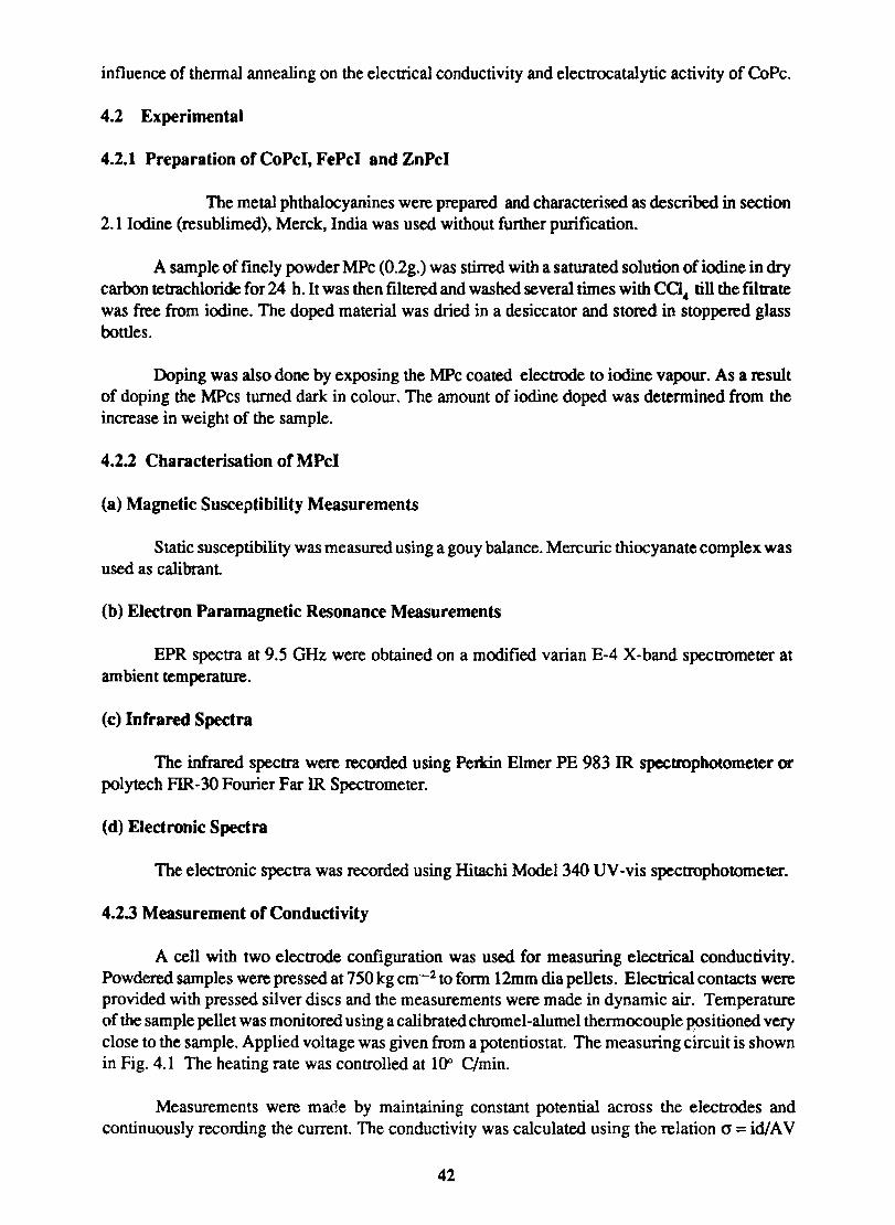
influence of thennal annealing on the elecnical conductivity and electrocatalytic activity of CoPc.
4.2 Experimental
4.2.1 Preparation of CoPcI, FePcI and ZnPcI
The metal phthalocyanines were prepared and characterised as described in section 2.1 Iodine (resublimed), Merck, India was used without further purification.
A sample of finely powder MPc (O.2g.) was stirred with a saturated solution of iodine in dry carbon tetrachloride for 24 h. It was then filtered and washed several times with ca .. till the filtrate was free from iodine. The doped material was dried in a desiccator and stored in stoppered glass bottles.
Doping was also done by exposing the MPc coated electrode to iodine vapour. As a result of doping the MPcs turned dark in colour. The amount of iodine doped was detennined from the increase in weight of the sample.
4.2.2 Characterisation of MPcI
(a) Magnetic Susceptibility Measurements
Static susceptibility was measured using a gouy balance. Mercuric thiocyanate complex was used as calibrant
(b) Electron Paramagnetic Resonance Measurements
EPR spectra at 9.5 GHz were obtained on a modified varian E-4 X-band spectrometer at ambient temperature.
(c) Infrared Spectra
The infrared spectra were recorded using Perkin Elmer PE 983 IR spectrophotometer or polytech FIR-30 Fourier Far IR Spectrometer.
(d) Electronic Spectra
The electronic spectra was recorded using Hitachi Model 340 UV-vis spectrophotometer.
4.2.3 Measurement of Conductivity
A cell with two electrode configuration was used for measuring electrical conductivity. Powdered samples were pressed at 750 kg cm-2 to fonn 12mm dia pellets. Electrical contacts were provided with pressed silver discs and the measurements were made in dynamic air. Temperature of the sample pellet was monitored using a calibrated chromel-alumel thermocouple positioned very close to the sample. Applied voltage was given from a potentiostat. The measuring circuit is shown in Fig. 4.1 The heating rate was controlled at 10" C/min.
Measurements were made by maintaining constant potential across the electrodes and continuously recording the current. The conductivity was calculated using the relation (J = id/A V
42

D E I
Fr-- --.------ --lA 1 , ,
•
:1 I ~ .... ( )8 • ~
, •• : I I , i
• I .- -- ----~tIII - T
T
Fig. 4.1 Block diagram showing the measurement of conductivity.
A: conductivity cell B: Sample C: Thennocoup1e D: Potcntiostat E: ElcctTOmcter F: Furnace
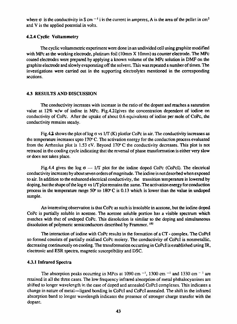
where 0' is the conductivity in S cm -I i is the current in amperes, A is the area of the pellet in cm2
and V is the applied potential in volts.
4.2.4 Cyclic Voltammetry
The cyclic voltammetric experiment were done in an undivided cell using graphite modified with MPc as the working electrode, platinum foil (I Omm X lOmm) as counter electrode. The MPc coated electrodes were prepared by applying a known volume of the MPc solution in DMF on the graphite electrode and slowly evaporating off the sol vent. This was repeated a number of times. The investigations were carried out in the supporting electrolytes mentioned in the corresponding sections.
4.3 RESULTS AND DISCUSSION
The conductivity increases with increase in the ratio of the dopant and reaches a saturation value at 12% w/w of iodine in MPc. Fig.4.2Jgives the concentration dependent of iodine on conductivity of CoPe. After the uptake of about 0.6 equivalents of iodine per mole of CoPc, the conductivity remains steady.
Fig.4.1 shows the plot oflog 0' vs Iff (K) plotfor CoPe in air. The conductivity increases as the temperature increases upto 1700 C. The activation energy for the conduction process evaluated from the Arrhenius plot is 1.53 eV. Beyond 1700 C the conductivity decreases. This plot is not retraced in the cooling cycle indicating that the reversal of phase transformation is either very slow or does not takes place.
Fig.4.4 gives the log 0' - Iff plot for the iodine doped CoPc (CoPcD. The electrical conducti vity increases by about seven orders of magnitude. The iodine is not desorbed when exposed to air. In addition to the enhanced electrical conductivity, the transition temperature is lowered by doping, but the shape of the log 0' vs VI' plot remains the same. The activation energy for conduction process in the temperature range 500 to 1800 C is 0.13 which is lower than the value in undoped sample.
An interesting observation is that CoPc as such is insoluble in acetone, but the iodine doped CoPe is partially soluble in acetone. The acetone soluble portion has a visible spectrum which matches with that of undoped CoPc. This dissolution is similar to the doping and simultaneous dissolution of polymeric semiconductors described by Frammer. 193
The interaction of iodine with CoPe results in the formation of a er -complex. The CoPcI so formed consists of partially oxidised CoPc moiety. The conductivity of CoPcI is nonmetallic, decreasing continuously on cooling. The transformation occurring in CoPcI is established using IR, electronic and ESR spectra, magnetic susceptibility and DSC.
4.3.1 Infrared Spectra
The absorption peaks occurring in MPcs at 1090 cm -I, 1300 cm -1 and 1330 cm - 1 are retained in all the three cases. The low frequency infrared absorption of metal phthalocyanines are shifted to longer wavelength in the case of doped and annealed CoPcI complexes. This indicates a change in nature of metal-ligand bonding in CoPcI and CoPcI annealed. The shift in the infrared absorption band to longer wavelength indicates the presence of stronger charge transfer with the dopant.
43
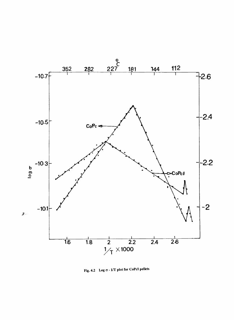
-10.7
-10.5
-10·3 b C) o
-10.1
352
1.6
282
1.8 2 2.2 YT Xl000
Fig. 4.2 Log a - lIT plot for CoPc1 pellets
144 112 - 2.6
-2.4
- ... 2.2
-2
2.4
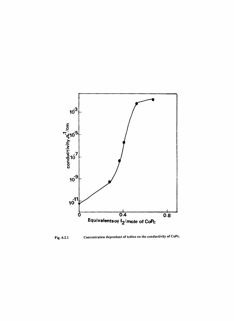
... (.) ·7 -610 c' o (.)
·11 10
o 0.4 0.8 .EquivalentsOf '2/mo1e of CoPe
Fig. 4.2.1 Concentration dependant of Iodine on the conductivity of CoPe.
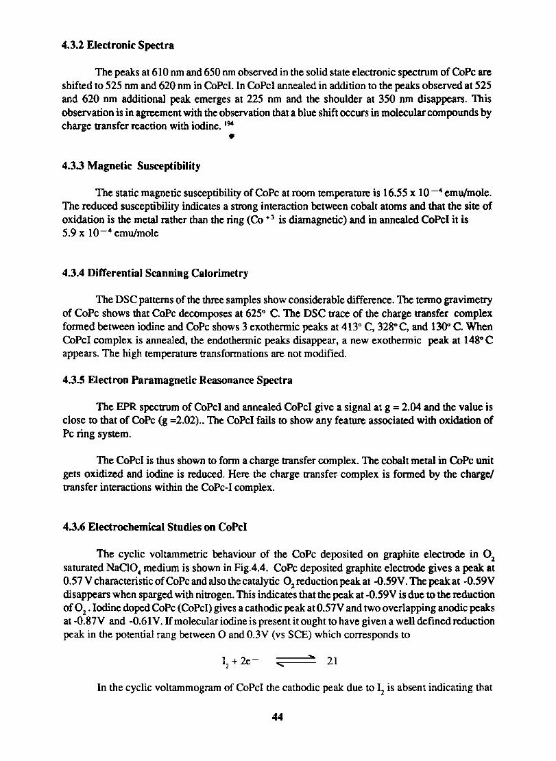
4.3.2 Electronic Spectra
The peaks at 610 nm and 650 nm observed in the solid state electronic spectrum of CoPc are shifted to 525 nm and 620 nm in CoPcI. In CoPcI annealed in addition to the peaks observed at 525 and 620 nm additional peak emerges at 225 nm and the shoulder at 350 nm disappears. This observation is in agreement with the observation that a blue shift occurs in molecular compounds by charge transfer reaction with iodine. 194
• 4.3.3 Magnetic Susceptibility
The static magnetic susceptibility of CoPc at room temperature is 16.55 x 10 -4 emu/mole. The reduced susceptibility indicates a strong interaction between cobalt atoms and that the site of oxidation is the metal rather than the ring (Co +3 is diamagnetic) and in annealed CoPcI it is 5.9 x 10⁻⁴ emu/mole
4.3.4 Differential Scanning Calorimetry
The DSC patterns of the three samples show considerable difference. The tenno gravimetry of CoPc shows that CoPc decomposes at 625° C. The DSC trace of the charge transfer complex fonned between iodine and CoPc shows 3 exothennic peaks at 413° C, 328°C, and 1300 C. When CoPcI complex is annealed, the endothennic peaks disappear, a new exothennie peak at 148° C appears. The high temperature transfonnations are not modified.
4.3.5 Electron Paramagnetic Reasonance Spectra
The EPR spectrum of CoPeI and annealed CoPcI give a signal at g = 2.04 and the value is close to that of CoPc (g =2.02) .. The CoPcI fails to show any feature associated with oxidation of Pc ring system.
The CoPcI is thus shown to fonn a charge transfer complex. The cobalt metal in CoPc unit gets oxidized and iodine is reduced. Here the charge transfer complex is fonned by the charge! transfer interactions within the CoPc-I complex.
4.3.6 Electrochemical Studies on CoPcI
The cyclic voltammetric behaviour of the CoPc deposited on graphite electrode in 02 saturated NaCI04 medium is shown in Fig.4.4. CoPc deposited graphite electrode gives a peak at 0.57 V characteristic of CoPc and also the catalytic 02 reduction peak at -O.59V. The peak at -0.59V disappears when sparged with nitrogen. This indicates that the peak at -0.59V is due to the reduction of °2 , Iodine doped CoPc (CoPcI) gives a cathodic peak at 0.57V and two overlapping anodic peaks at -O.87V and -0.61 V. H molecular iodine is present it ought to have given a well defined reduction peak in the potential rang between 0 and 0.3V (vs SCE) which corresponds to
I + 2e- --===~... 21 2 '"
In the cyclic voltammogram of CoPcI the cathodic peak due to 12 is absent indicating that
44
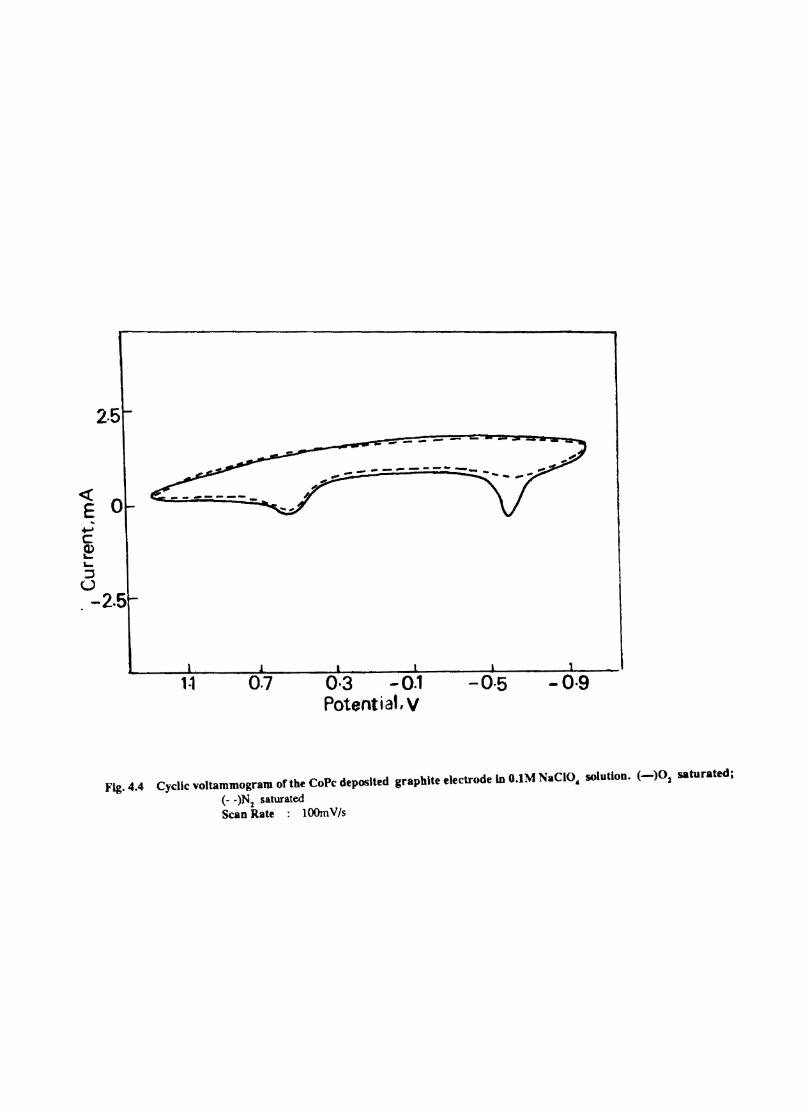
2·5 ..------ -
~ 0 ~
+-' C e L...
:J U . -2.5
0·3 -0.1 Potent i at, V
-0·5 -o·g
Fig.4.4 Cyclic yoltammogram of the CoPe deposited graphite electrode in O.IM NaCIO, solution. (-)01 saturated;
(- -)N1 saturated Scan Rate : lOOmV/s
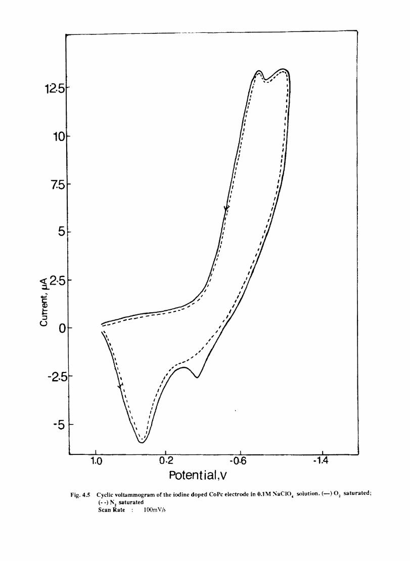
12·5
10
7.5
5
-2.5
-5
I
to 0.2 -0.6
Potential,v Fig.4.5 Cyclic voltammogram of the iodine doped CoPe electrode in O.lM ~aCIO~ solution. (-) O2 saturated;
(- -) ]1\2 saturated Scan Rate lOOm V /~
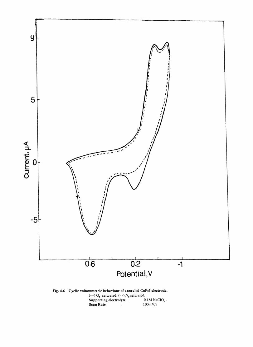
5
... C (1)0 ''-:::J U
-5
0·6
" --.. ' , , ,
, ,
, , I ,
I I I
I I I
. I , I t
Potential ,v
I , , I
I ,
Fig.4.6 Cyclic voltammetric behaviour of annealed CoPcJ electrode. (-) 02 saturated; (- -) N2 saturated. Supporting electrol,yte 0.1 M NaCI04 •
Scan Rate lOOmV/s
-1
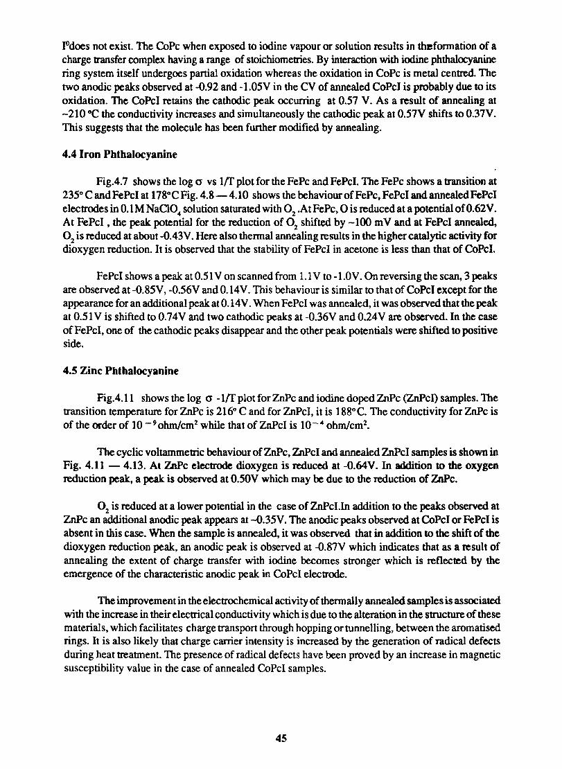
IOdoes not exist. The CoPc when exposed to iodine vapour or solution results in thefonnation of a charge transfer complex having a range of stoichiometries. By interaction with iodine phthalocyanine ring system itself undergoes partial oxidation whereas the oxidation in CoPc is metal centred. The two anodic peaks observed at -0.92 and -l.OSV in the CV of annealed CoPcI is probably due to its oxidation. The CoPc] retains the cathodic peak occurring at 0.S7 V. As a result of annealing at -210°C the conductivity increases and simultaneously the cathodic peak at 0.57V shifts to 0.37V. This suggests that the molecule has been further modified by annealing.
4.4 Iron Phthalocyanine
Fig.4.7 shows the log 0" vs Iff plot for the FePc and FePcl. The FePc shows a transition at 23So C and FePcI at 178°C Fig. 4.8 - 4.10 shows the behaviour of FePc, FePcI and annealed FePcI electrodes in 0.1 M NaClO. solution saturated with 02 .At FePc, ° is reduced at a potential ofO.62V. At FePcI , the peak potential for the reduction of 02 shifted by -100 m V and at FePcI annealed, 02 is reduced at about -0.43V. Here also thermal annealing results in the higher catalytic activity for dioxygen reduction. It is observed that the stability of FePcI in acetone is less than that of CoPc!.
FePcI shows a peak at 0.51 V on scanned from 1.1 V to -I.OV. On reversing the scan, 3 peaks are observed at -0.8SV, -0.S6V and 0.14V. This behaviour is similar to that of CoPcI except for the appearance for an additional peak at 0.14V. When FePcI was annealed, it was observed that the peak at 0.51 V is shifted to 0.74V and two cathodic peaks at -0.36V and 0.24V are observed. In the case of FePcI, one of the cathodic peaks disappear and the other peak potentials were shifted to positive side.
4.5 Zinc Phthalocyanine
Fig.4.ll shows the log er -Iff plot for ZnPc and iodine doped ZnPc (ZnPcl) samples. The transition temperature for ZnPc is 216° C and for ZnPcI, it is 188°C. The conductivity forZnPc is of the order of 10 -9 ohm/cm2 while that of ZnPcI is 10 -. ohm/cm2•
The cyclic voltammetric behaviour of ZnPc, ZnPcI and annealed ZnPcI samples is shown in Fig. 4.11 - 4.13. At ZnPc electrode dioxygen is reduced at -O.64V. In addition to the oxygen reduction peak, a peak is observed at 0.50V which may be due to the reduction of ZnPc.
02 is reduced at a lower potential in the case of ZnPcl.In addition to the peaks observed at ZnPc an additional anodic peak appears at -o.35V. The anodic peaks observed at CoPc] or FePcI is absent in this case. When the sample is annealed, it was observed that in addition to the shift of the dioxygen reduction peak, an anodic peak is observed at -O.87V which indicates that as a result of annealing the extent of charge transfer with iodine becomes stronger which is reflected by the emergence of the characteristic anodic peak in CoPcI electrode.
The improvement in the electrochemical activity of thermally annealed samples is associated with the increase in their electrical conductivity which is due to the alteration in the structure of these materials, which facilitates charge transport through hopping or tunnelling, between the aromatised rings. It is also likely that charge carrier intensity is increased by the generation of radical defects during heat treatment. The presence of radical defects have been proved by an increase in magnetic susceptibility value in the case of annealed CoPcI samples.
45
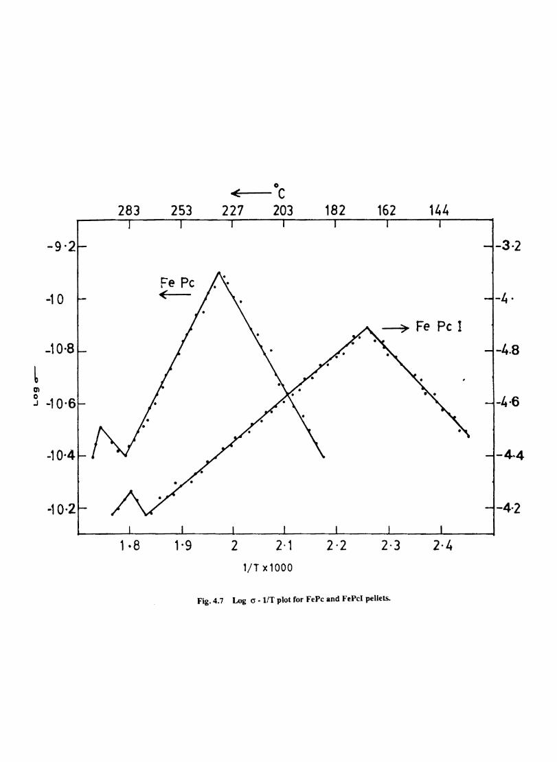
-9 ·2
-10
-10·8
en o .J -10'6
-10·4
283 253
Fe Pc <
1 • 8 1·9
0
< C 227 203 182 162 144
-3·2
-4·
-4.8
-4·6
-4·4
-4'2
2 2·1 2·2 2·3 2·4
l/T x1000
Fig. 4.7 Log 0"' lIT plot for fePc and fePeI pellets.
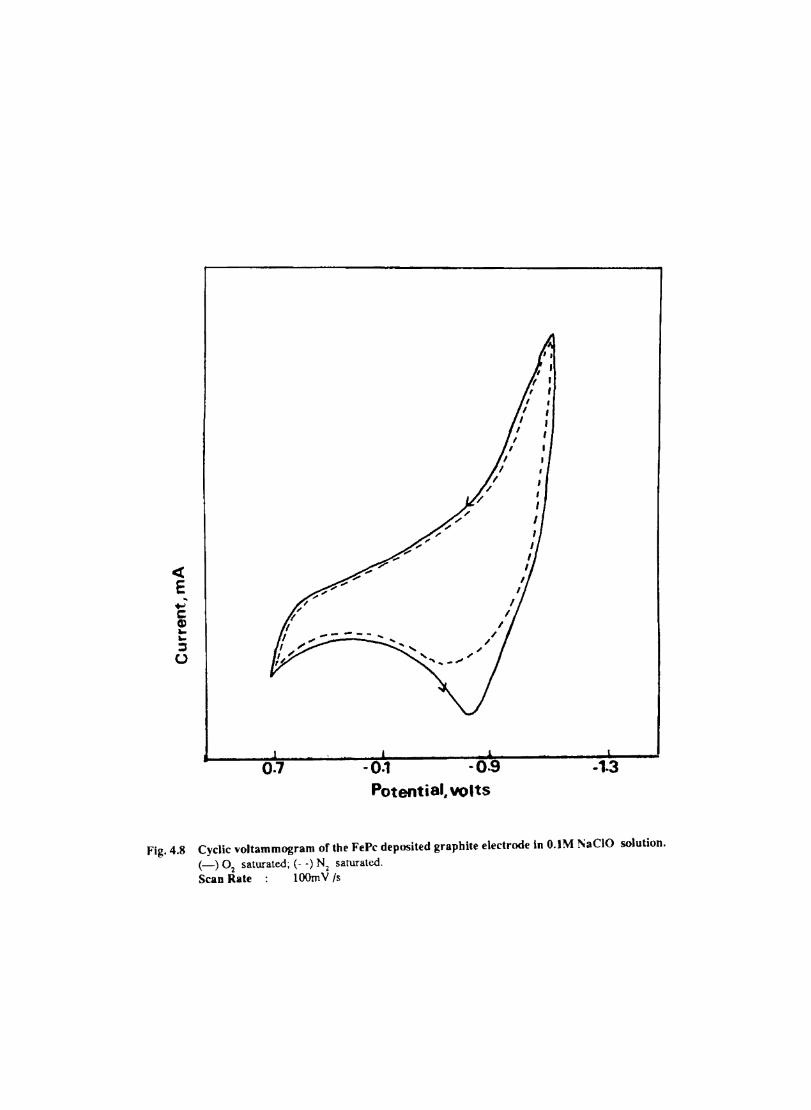
<[
E -... c Cl) --::s U
0.7
I I
I
" "
·0.1 ·0.9 Potential. volts
I I
I I
-1·3
Fig.4.8 Cyclic voltammogram of the FePc deposited graphite electrode In O.lM l'iaClO solution. (-) 02 saturated; (- -) N2 saturated. Scan Rate lOOmV Is
« E
...., s:: Cl.I L. L. ~ u
2·5
0
-2·5
- .................. _-""
- 0·1 Potential volts
-0·5 -o·g
Fig.4.9 Cyclic voltammogram of the iodine doped FePc electrode in O.lM NaCI04 solution. (_) 02 saturated; (- -) Nz saturated
Scan Rate lOOm V Is
1- 0
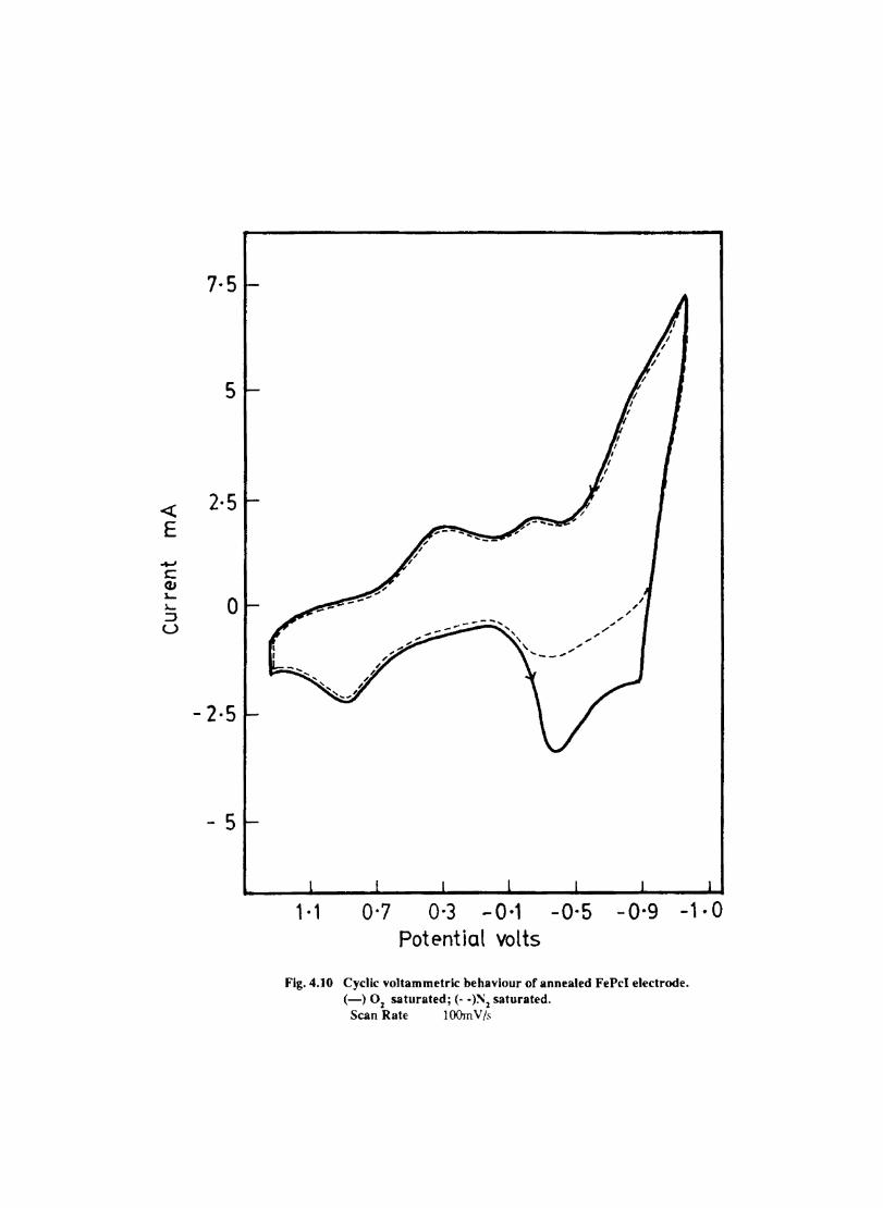
7·5
5
2-5
o
- 2-5
- 5
1·1 0-7
" .... " " .... _-,.".
... ."
, , I ,
0·3 - 0·1 -0-5 -O·g -1·0 Potential volts
Fig.4.10 Cyclic voltammetric behaviour of annealed FePeI electrode. (-) 02 saturated; (. -)~2 saturated.
Scan Rate ] 00m V /s
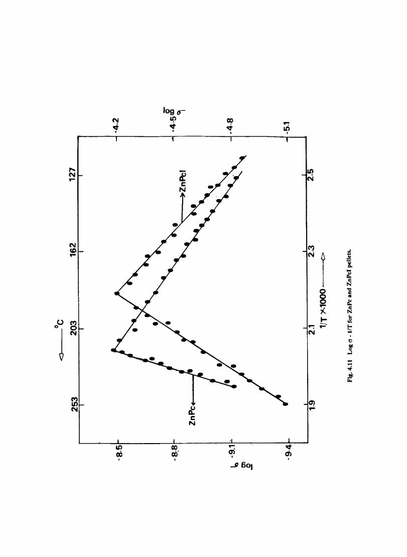
cO
J
,... N -
N CD -
C"l 0 N
M Lt) N
-
N ..t
I
it)
06 •
log 0 it)
~
CO rii •
~ I:
N
co ~
I
-cri
....9 601
-. an •
~ ch •
an N
C'1 N
~
N
O? -
I I
0
8 -i.. ~ --
!l ~ 'ii ~ ... ~ J:: N 'a J:: • ~ J:: N ... .E t -0
~ ..J ... ... ~ ~ fi:
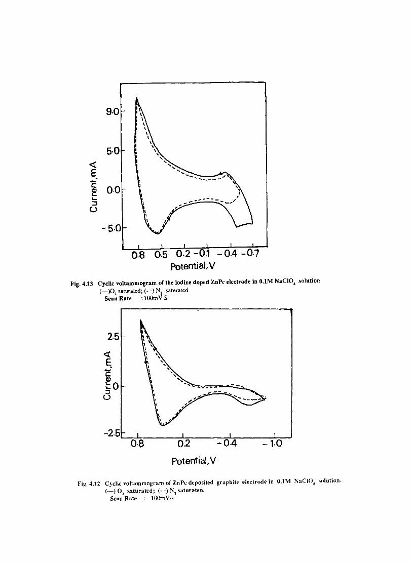
9·0
5·0
-5·0
0.8 Potential, V
Fig.4.13 Cyclic voltammogram ofthe Iodine doped ZnPc electrode in O.lM NaCIO. solution (-)02 saturated; (- -) Nz saturated
San Rate ; lOOmV S
2·5
<C ~ -C Cl) to :::l
U
-2.5 ~0~·8~--~0.~2-----~O~.4~----J,.O~
Potential, V
Fig.4.12 Cyclic voltammogram of ZnPc deposited graphite electrude in 0.1\-1 l\aClO. sulution.
(-) 01 saturated; (- -) ~l saturated. Scan Rate ; lOOmV/s
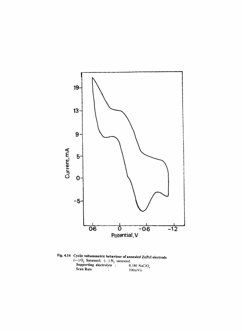
« E
13
9
5
o
-5
0-6 o -0.6 Potential, V
Fig.4.14 Cyclic voltammetrlc behaviour of annealed ZnPcI electrode (-) 02 Saturated; (- -) Nl sanu-ated.
Supporting electrolJte O.lM NaCI04
Scan Rate lOOrnV/s
-1.2
CHAPTER V
Chemically Modified Electrodes
5.1 Introduction
Eventhough electrochemical methods have a wide range of applications in analysis, inorganic and organic synthesis. catalysis, display-devices etc., fouling of the electrode surface by the undesirable precipitation or adsorption of reactants and products and the necessity for applying an overvoltage due to slowness of electron transfer for certain species are some of its major disadvantages. It is anticipated that by attaching chemical reagents to an electrode surface the chemical properties of the attached reagents can be imparted to the surface. If the proper reagent is chosen, desirable properties such as reagent -based control of the rates, selectivity of electrochemical reaction, freedom, from adsorptive and coating effects, and special photochemical features might be obtained. The application of such chemically modified electrodes (CME) has opened up new vistas in the field of electrochemical research. Interest in (CME) has opened up new vistas in the field of electrodes. Interest in CMEs has spread in varied directions, including synthetic design of electrochemically active polymers, basic studies on electrocatalysis, electron transfer kinetics, membrane permeation, electrochromics, photoelectrochemistry, molecular electronics and electroanalysis. 196-200.
The different methods for the modification of electrode by the immobilization of chemical reagents are:
I.Monomolecular layer formation by the chemisorption of reagent. a) On Platinum surface 19&
b) On carbon surface 201
c) On mercury surface 202
d) Gold surface 203
2. Formation of covalent bond formation between electrode and electroactive and electroinactive reagent
a) At metal oxide surface 204
b) At carbon surface 205
c) At semiconductors 206
d) Of electroinactive, chiral substances 207
3. Multimolecular layers, polymer fIlm coatings on electodes a) Redox polymers 208
b) Ion exchange electrostatically trapped 209
c) Electronically conducting polymers 210
d) Ionically conducting polymers 211
e) Crown ether or complexing agent 212
f) Electroinactive chiral polymers 213
4.Heterogeneous multimolecular layers a) Modifying agent mixed with carbon paste 214
b) Clay modified 215
c) Electroactive particles in electroactive polymer 216
46
In the initial phase of development monolayers or submonolayers of electroactive species were irreversibly attached to the electrode surface. Carbon electrodes are especially effective with chemisoroing reagents that have extended TI-bond system. An example is the chemisorption of a dicobalt cofacial pOIphyrin electrocatalyst (COl FTF <4) onto pyrolytic carbon to create an electrode that mediates the 4 electron reduction of dioxygen.
The use of chemical functionalities of electrode surfaces for anchoring reagents has wide range of synthetic diversity and has been extensively developed for attaching monomolecular and multimolecular layers of electroactive substances to metal oxides and carbon semiconductors electrodes.
Electroactive multimolecular layer films of polymers are popular today because they are technically easier to apply to electrodes than are covalently bonded monolayers. They also contain multimolecular layers of electroactive sites, so that their electrochemistry can be more easily observed. Electroactive films can be used as electrocatlysts, as preconcentration media or as transport barrier, where the perfonnance of monolayer films are not reliable. Bare or monolayerderivatised electrodes permit reduction only in an essentially 2-dimensional zone next to the electrode, whilst homogeneous reactions occur in a 3-dimensional zone, pennitting a greater reaction flux. By using thicker modifying films, homogeneous catalysis can take place successfully. Thicker polymeric films are advantageous in corrosion protection by charge transfer blocking and in optical displays by immobilizing redox-state-dependent chromophores.
Electroactive polymer films are intrinsically conductive du' to both ions and electrons. There are three kinds: Redox polymers, electronically conducting polymers, and ion exchange polymers. Polymer films with redox sites (localized electronic states), called redox polymers, conduct electricity via electrons hopping between oxidized and reduced sites. The possible use of polypyrrole in electrocatalysis and other related applications has been reviewed by Derronzier et al l17
• This is the case with o-quinone, pyrrole, substituted porphyrin and ferrocene polymers. The organic metals or electronically conducting polymers conduct via delocalized. metal-like band structures. Polypyrrole is such a material which can be easily prepared by electrochemical polymerization and can be used to entrap electrocatalysts such as phthalocyanines 211 and enzymes.
Ion exchange polymer fJ.1ms are made electroactive by the exchange of some of their chargecompensating counterions forelectroactive ones. Exchange of Fe(CN)6<4- for the CI04 - counter ion of a protonated polyvinylpyridine fllm is an example. Ion exchange equilibrium can be slowly reversed when the polymer is used in an electrolyte solution free of electroactive counter ions. The electroactivity sites of ion exchanged polymer is labile compared to those of covalently bound redox polymers. In the ion exchange films, electrons are transported in part by physical diffusion of electroactive ions, which may also undergo self-exchange as part of the transpon process.ll9 The electrical properties of electroactive polymer films on electrodes and the processes by which they electrocatalytically mediate electron transfers between the electrode and reactive substrates in the contacting solution S a field of active research now. Ionic conductivities of the films have been less fully investigated but need to be better understood. because of electroneutrality a change in the films oxidation state requires movement of charge-compensating counter ions in film.
Heterogeneous films on electrodes can be designed to contain a mixture of constituents with different functions. An example is the addition of constituents such as catalyst monomers and metal complexing agents to carbon paste electrodes.
"The mixed carbon paste electrodes" made from carbon paste which is doped during
47
preparation with the modifying molecule is marked with the following advantages: simplicity of electrode fabrication procedures, wide flexibility for the attachment of numerous organic and organometallic moieties, convenient control over the modifier concentration and capability for easy renewal of the CME surface.
The electrochemical properties of the polymers can be used for the controlled release of chemicals, especially drugs 220-222. The basic concept of this application is to bind the drug into a polymer film on an electrode and release the drug as needed by passing a small current through the polymer.
Though catalytic properties of macrocylic transition metal complexes such as porphyrins and phthalocyanines for an electrochemical oxygen reduction have been recognized and examined extensively by many workers, an active, inexpensive and stable catalyst system has not yet been discovered 223,21A. In this connection special efforts are made to modify the inexpensive materials such as graphite with electroactive substances. Utilization of modified catalytic electrode at monolayer level has not been so successful in that they lack stability and conductivity in a doped state due to the unstable and insulating nature of adsorbed species on the substrate 125.226.
Electrocatalytic materials have been incorporated into polymer-coated electrodes which is an easy and potential means of ftxing a large metal complex as active catalyst on the substrate 227.
Polymer films can be deposited on an electrode by electrooxidative polymerization simultaneously with the incorporation of active materials from the supporting electrolyte. The electrocatalytic activity for oxygen reduction was improved at a glassy carbon electrode modified with polypyrrole/ (tetrasulfonatophthalocyaninatocobalt) electrode22l• CoTS Pc can also be doped intopolyaniline 229
and this shows very good catalytic activity and stability for dioxygen reduction.
5.2 Polymer Modified Electrodes
5.2.1 Electrocbemical Characterization
The behaviour of an electrode coated with polymer and its improvements in design and perfonnance and the resulting interface must be characterised fully. Prominent amongst the pieces of information desired are the following 230.
a) Polymer Structure: The nature of polymer/electrode bonds (if present), interchain interactions and, particularly for in situ polymerised films, the nature of linkage between repeat units.
b) Film thickness and the degree of uniformity therof,
c) The extent to which monomer properties (E'electron transfer rate constants, optical behaviour, etc) are carried over to the polymer;
d) the local environment, notably extent of solvation and solution anion/cation incorporation.
e) the redox composition/potential relation
f) the presence (or otherwise of electrostatic or other interactions between redox centtes and the remainder of the polymer structure and possible resultant structural inhomogeneity.
g) The rates of electron and ion motion through the film, ie. the conductivity and the mechanism of
48
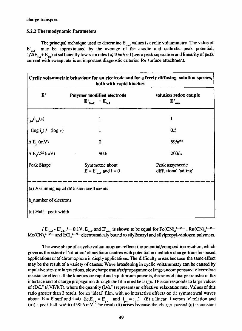
charge transport
5.2.2 Thermodynamic Parameters
The principal technique used to determine E'-r values is cyclic voltammetry· The value of E'.un may be approximated by the average of the anodic and cathodic peak potential, l!2(Ep .. + Ep..) at sufficiently low scan rates ( c;: 1 Om Y 5-1) .zero peak separation and linearity of peak current with sweep rate is an important diagnostic criterion for surface attachment
Cyclic votammetric behaviour for an electrode and for a freely diffusing solution species, both with rapid kinetics
El
ip,/ip..,(a)
(log i) 1 p (log v)
L\ E (mY) p
L\ EP(C) (mY)
Peak Shape
Polymer modified electrode EtSurf = E . .,.
1
1
0
90.6
Symmetric about E =E' andi =0 fIlrf
solution redox couple E'
8DID
1
0.5
59/n(b)
203/n
Peak assymetric diffusional 'tailing'
~------------------------------------
(a) Assuming equal diffusion coefficients
b number of electrons n
(c) Half - peak width
I E'm! - E'mIn I = 0.1 Y. EIIIl'f and E'm is shown to be equal for Fe(CN)63-,14- ,Ru(CN)63--J'
Mo(CN).~ and IrCI61~electrostatica1y bound to silylbenzyl and silylpropyl-viologen polymers.
The wave shape of a cyclic voltammogram reflects the potential/composition relation, which governs the extent of 'titration' of mediator centres with potential in mediator charge-transfer-based applications or of chromophore in disply applications. The difficulty arises because the same effect may be the result of a variety of causes: Wave broadening in cyclic voltammetry can be caused by repulsive site-site interactions, slow charge transfer/propagation or large uncompensated electrolyte resistance effects. If the kinetics are rapid and equilibrium prevails, the rates of charge transfer of the interface and of charge propagation through the film must be large. This corresponds to large values of (D/L 2 )/(VFIRT), where the quantity (OIL 2 ) represents an effective relaxation rate. YaIues of this ratio greater than 3 result, for an 'ideal' film, with no interactive effects on (i) symmetrical waves about E = E surf and i =0 (ie.E = E and i = i ) (ii) a linear i versus 'v' relation and p.. p~ p.. p~
(iii) a peak half-width of 90.6 m V. The result (ii) arises because the charge passed (q) is constant
49
and provides, fIrstly an important diagnostic test for surface attachment and secondly, a means of determining the total number of electroactive centres (r Imol Cm ).
r =q/nFA
The presence of interactive effects alters peak half-width and equality of peak currents (although they may still be individually proportional to scan rate if rapid kinetics prevail). Repulsive or attractive interactions result in peak lm»dening or narrowing respectively.
Kinetic Parameters
Cyclic voltammetry can be used in two ways to determine kinetic data. In the first, the scan time is sufficiently long for the entire film to have the opportunity to react and one may follow the course of comparatively slow film changes. In the second, one assumes that the film is not involving itself in any way, and uses scan rate as the time domain variable to probe the rate of process associated with redox changes involving the film.
An obvious application of the first type of experiment is as a monitor of electroactive redox centre population during film production/elaboration by redox couple incorporation, ion exchange, silylation or electro-polymerisation. In the latter case, film growth and polymerisation are intimately linked, but the act of cycling the potential is also important in the ion exchange of Ru(bipY)31+ into poly(styrene sulphonate) films. Similarly, the loss of electroactive species has been followed by cyclic voltammetry and also that induced by it, in the case of H+ reduction within a protonated pyridine iodide system. In most cases the distinction between redox centre loss and isolation, polymer loss, require more direct data for confmnation.
Reaction (rather than loss) of redox centres may be followed by the appearance (and integration of) peaks at different E'aurf or by the loss of reactant peak if the product is electroinactive.
5.3 ELECTROCHEMICAL BEHAVIOUR OF COBALT TETRASULPHO -PHTHALOCY ANINE ION DOPED INTO POLY ANILINE AND POLY (0-TOLUIDINE)
5.3.1 Introduction
Polyaniline (PA) is an interesting conducting polymer with a wide range of conductivity including that approach 5 Stcm 231 • Electrochemically formed PA is generally homogeneous, strongly adherent to the electrode surface and chemically stable. 232.233. The electrochemical behaviour of PA depends on its method of preparation 234 and the substrate 23S on which it is formed and also on the temperature 236 of synthesis. The conducting or insulating and electroactive or inactive property of PA depends on the experimental conditions used for its preparation.238
Poly aniline can be electrochemically polymerized onto electrodes such as platinum and pyrolytic graphite 2392AO This technique has many advantages like homogeneity strong adherence to electrode surface and chemical stability and the characteristics are reproducible.
PA films have been used as chemical sensors in microelectronic devices, cathode materials in solid state batteries, ion exchangers, display elements in electrochromic devices and as electrocatalysts 241.2
42. Polyaniline based devices can be turned 'on' by either a positive or a negative shift of the
electrochemical potential, because the films are essentially insulating at sufficiently negative (- O.OV vs SCE) or positive (-o.7V vs SCE) applied potentials. The response of PA based transistors to a
50
signal thus differs in a significant way from solid-state transistors where the current passing between the source and the drain I at a given source drain voltage, V • does not decrease with increasing gate voltage. V . When a macroscopic electrode is derivatized with a redox polymer and then coated with a porous metal contact. it can show diode-like behaviour 243.
Platinum microparticles can be electrodeposited as a three dimensional array in a polyaniline film 244. These electrodes show high activity for hydrogen evolution and methanol oxidation. Metalloporphyrins and phthalocyanine can be incorporated into PA and they show very good catalytic activity and stability for dioxygen reduction. 24S.
In this chapter the results of the studies of the electrode process on cobalt tetrasulphophthalocyanine modified polyaniline are reported.
5.3.2 EXPERIMENTAL
5.3.3 Chemicals
Reagent grade aniline (Glaxo Laboratories, Bombay) was vacuum distilled and the middle fraction was used. Other chemicals used were of guaranteed purity.
5.3.4 Electrodes, Electrochemical Cells and Instrumentation
Electrochemical cell and instruments used in this study were the same as those described in section 3.1 .Unless otherwise specified experiments were done in dearated solutions
Spectroscopic grade graphite (Union Carbide. USA), platinum wire or platinum button and carbon paste electrodes were used as the working electrodes.
The graphite electrode of exposed area 0.8 cm2 was made by sealing the graphite electrode in a thick walled glass tube with epoxy resin and polishing the surface with fine carborundum powder.
5.3.5 Carbon paste electrode
Dry, chemically fonned polyaniline (l-5mg) and carbon powder (5-10 mg) were thoroughly mixed in a mortar and mulled with a drop of Nujol until the entire mixture appeared unifonnly wetted. A portion of this paste was then introduced into the cavity of a glass tube fitted with a platinum wire connected to a mercury contact. Connections were made through a copper wire immersed in mercury. This electrode gives a very low residual current over the entire range of potential studied.
A saturated calomel electrode was used as the reference electrode.
5.4 Preparation and Characterization of Polyaniline Films
Electrochemical preparation
A variety of electrochemical techniques and conditions are reported for the preparation of polyaniline f ms.
51
· 5.4.1 Graphite Electrode
PA film was deposited on graphite from a solution of O.5M ~SO. /0.1 M aniline by cycling the electode potential between 1.2V and -0.2V vs SCE.
5.4.2 Platinum electrode
A platinum wire (length 3mm) or button electrode (area-7mm2 ) was used as the working electrode. Aniline was polymerised onto the electrode as described in section 5.4.1
The polyaniline fIlm fonned were characterized by IR spectroscopy.
5.4.3 Chemical Preparation of Polyaniline
Aniline (5ml) was dissolved in 50ml of 4M ~SO. and 50 ml of aqueous solution of 40% ammonium persulphate was added. The resulting solution was warmed on a water bath for abouth 1h. The polymer precipitated out was filtered,washed with distilled water and dried. The PA was characterized by IR spectroscopy.
5.5 Results and Discussion
Fig 5.1. 1 shows the polymerisation of aniline at a graphite electrode. The frrst cycle shows two anodic peaks of aniline which are due to the oxidation of aniline. Subsequent potential cyclings indicate a regular growth of the polymer deposit. The PA film was allowed to grow for about twenty minutes. The electrode was taken out from the solution, washed several times with distilled water and placed in 0.5M ~SO 4' This electrode was cycled between -0.2 to 1.2V Fig. 5.2 shows the cyclic voltammetric behaviour of this electrode. The following peaks are observed in the CV: Anodic peaks at 0.21V, O.44V and 0.75V and Cathodic peaks at 0.51 V, 0.38V and 0.56V.
On repeated potential cycling it was seen that the anodic peak cunent at O.75V increases in magnitude. When the anodic limit of the potential scan did not exceed O.7V a single anodic peak at 0.21 V and two shoulder cathodic peaks at -O.16V and O.OV were only observed. The magnitude of the anodic peak current depends on the pH of the medium. It is also seen that the anodic potential is shifted to more negative values when the concentration of the acid is increased (Fig.5.3)
The same observations were obtained when the rilin was formed from neutral (N8.zHPO" I Nal\ PO;04.5M; pH = 7) and from alkaline medium (O.5MKOH)
The cyclic voltammetric behaviour of PA at Pt electrode is shown in Fig.5.4. This shows 2 pairs of distinct redox peaks at -O.7V and -0.1 V. Another pair is also observed at -O.5V which is not so prominent.
The electroactivity of aniline depends on the pH of the medium from which it is formed. It is also observed that PA formed from O.5M ~S04 is active only in pH <3, with an increase in pH, the anodic and cathodic peakpotentials shift to more negative values and also the anodic and cathodic peak currents decrease.
52
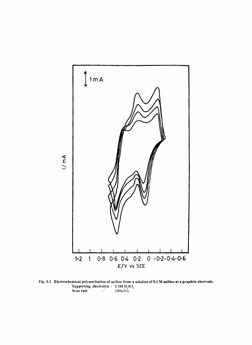
-et E
..........
1-2 1 0'8 0·6 0·4 0·2 0 -0'2-0·4-0·6 E/V vs SCE
Fig.S.1 Electrochemical polymerisation of aniline from a solution orO.1 M aniline at a grapbite electrode. Supporting dectrolytf: O.5M H2SO. Scan raCe 1 Ot..1mV/s
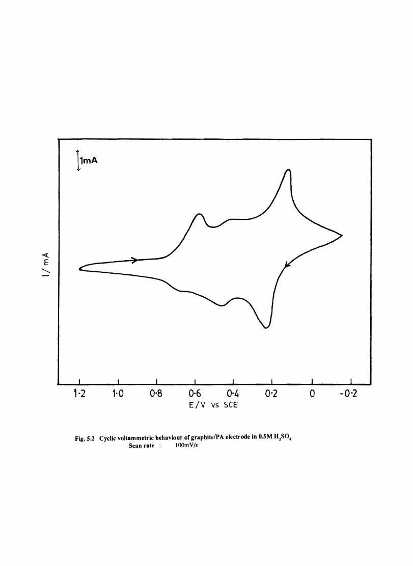
, -2 1-0 0-8 0-6 0-" ElY vs SCE
0-2
Fig. S.2 Cyclic voltammetric behaviour of graphite IPA electrode in O.5M H2S04
Scan rate: lOOm V /s
o -0-2
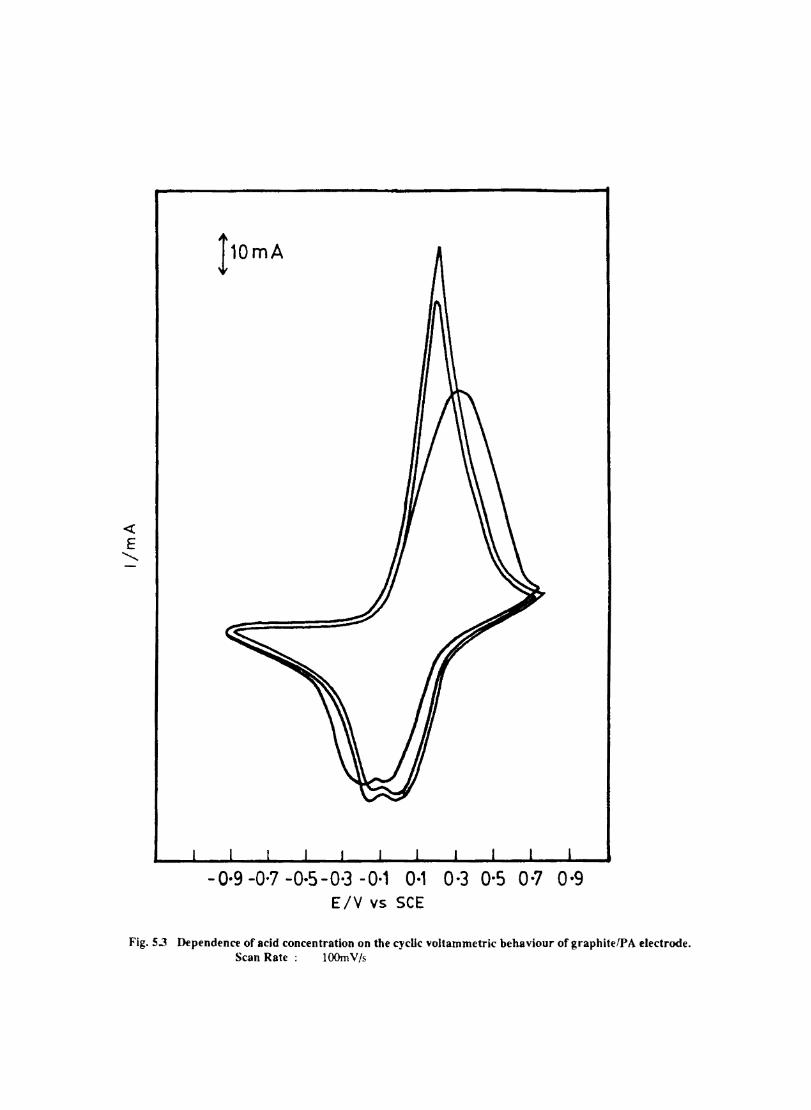
<{
E ..........
-o·g -0-7 -0-5-0-3 -0-1 0·' 0-3 0-5 0-7 o·g E/V vs SCE
Fig.5.3 Dependence or acid concentration on tbe cyclic voltammetric bebaviour ofgrapbitefPA electrode. Scan Rate : lOOm V /s
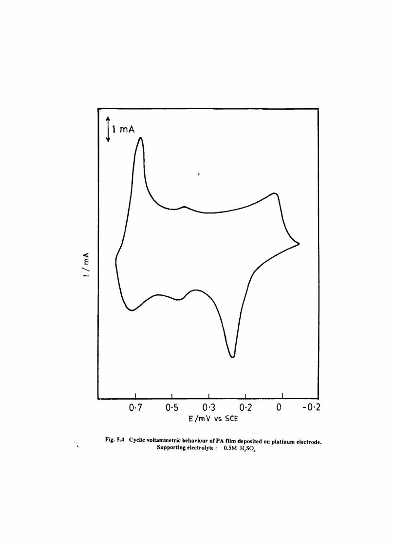
< E
..........
0·7 0·5 0·3 E/mV vs SCE
0·2 o -0·2
Fig.5.4 Cyclic voltammetrlc behaviour of PA film deposited on platinum electrode. , Supporting electrolyte: O.SM RzS04
5.6 Electrochemical Characterisation of Chemically Prepared Polyaniline.
The finely powdered polyaniline was made into a paste with carbon powder as described in section 3.5 and the potential was cycled in O.5M ~S04 . The resultant cyclic voltammograrn is shown in Fig.5.5. The CV shows three anodic and three cathodic peaks at the following potentials.
Anodic 0.78V, 0.56V and 0.24V and Cathodic O.64V, 0.35V and 0.02V
The positions of the peaks depend on the sweep rate. The square root of sweep rate is proportional to i (Fig.5.6). The results demonstrates that carbon paste electrochemistr}' can be
p conveniently extended to the electrochemical study of chemically prepared PA. The electroactivity of P Alcarbon paste electrode is comparable to that of graphite rod and platinum. The advantage of C/P A paste electrode compared to other electrodes are: the electrode fabrication is simple PA concentration can be conveniently controlled electrode surface can be easily renewed and also ease of handling of powder on a larger scale.
5.7 Electrochemical Preparation (CoTSP.PA) Electrodes
PA film was doped with CoTSP anion by electrochemically polymerizing aniline in the presence of CoTSP. The CoTSP-PA was prepared in 3 different ways.
i) The graphite electrode was soaked in 1.0 x 10 -3 M CoTSP solution for 20 minutes, washed with distilled water and a film ofPA was deposited overit by the galvanostatic oxidation of aniline inO.5M ~S04 at 2.5mA/cm2
• This electrode is denoted by C/CoTSPIPA.
ii) A film ofPA was galvanostatically deposited over the graphite as described above and then soaked in a solution of 1.0 X 10 - 3 M CoTSP for 20 min. The electrode was taken out and washed with distilled water. The resultant electrode is indicated by C/PAlCoTSP.
ili)The CI(PA + CoTSP) electrode was prepared as follows: A 1.0 x 10⁻³ M solution of CoTSP was mixed with 0.5M aniline in IM ~SO. Galvanostatic oxidation of aniline was done at a graphite electrode using this solution at a current of 2.5mAlcm2 •
A film of CoTSP doped PA was formed at the electrode. This was washed with dil. ~S04 and then with distilled water. Similarly (Pt/PAlCoTSP) and (Pt/CoTSP + PA) electrodes were also prepared. The CoTSP doped PA carbon paste electrode was prepared by mixing 2 mg. of CoTSP + 10 mg of PA and 50 mg of graphite powder with 2 drops of nujol. This was made into a paste and introduced into the cavity of a glass tube (5 mm Ld) Connections were made as described in section 5.2
5.8 Electrochemical Behaviour of CoTSP.PA Electrodes
5.8.1 Graphite
When the PA is doped with CoTSP, in all the three cases, it was found that the 3 cathodic peaks are well defined particularly the middle peak which was not resolved in the case of bare PA. (Fig. 5.7) Compared to bare PA, the peak potentials are shifted to more negative values. The peak. currents also increase substantially compared to those on PA films.
53
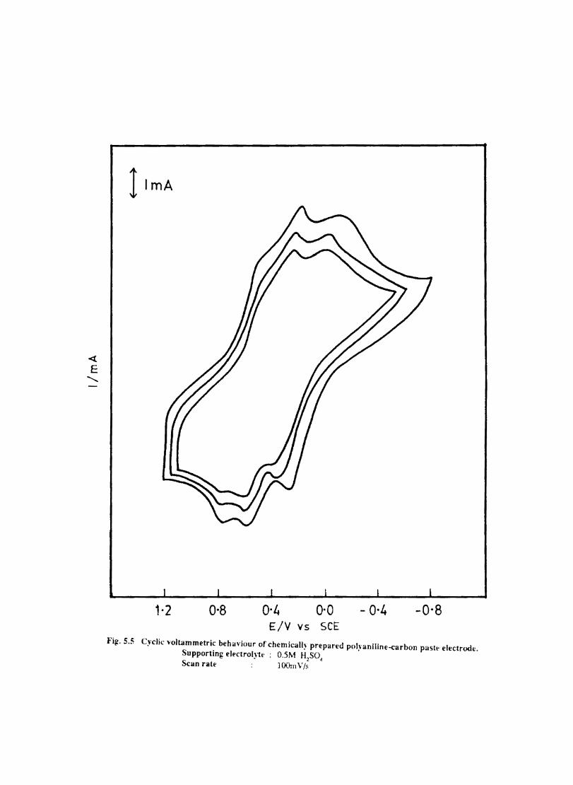
I lmA
1· 2 0-8 0·4 0·0 - 0-4 -0-8 E/V vs SCE
Fi~. 5.5 Cyclic ,ioltammetric beha,·jour of chemicall~ prepared polyaniline-carbon paste electrode. Supporting elpctrol}tf : O.5M H2S0~ Scan rate ]OOrnV/s
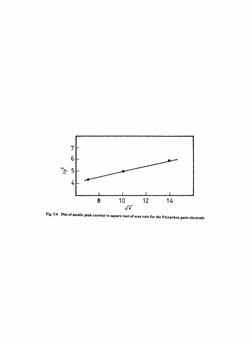
7
6 u
5 0-
~
8 10 12 14 Vv
Fig.5.6 Plot of anodle peak current vs square root of scan rate for tbe PA/carbon paste electrode
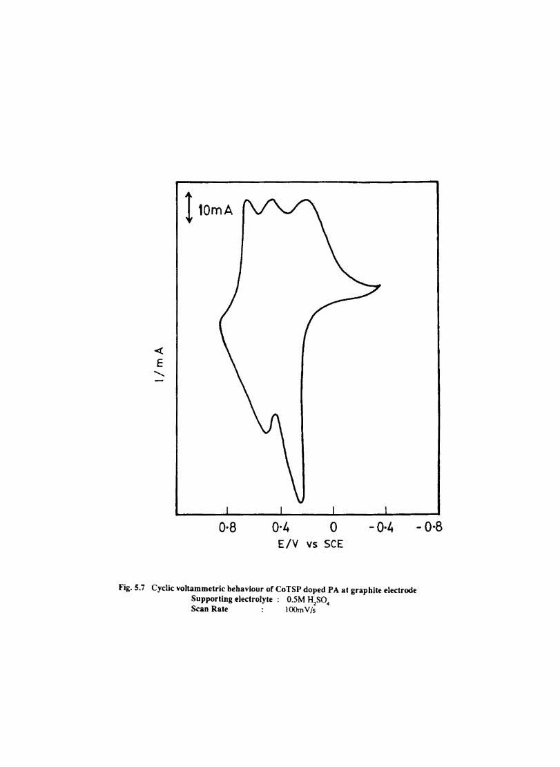
« E
........
110mA
o·a 0·4 o -0·4 E/V vs SCE
Fig. S.7 Cyclic voltammetr-lc behaviour of CoTSP doped PA at graphite electrode Supporting electrolyte: O.SM H2S04
Scan Rate lOOmV/s
- 0·8
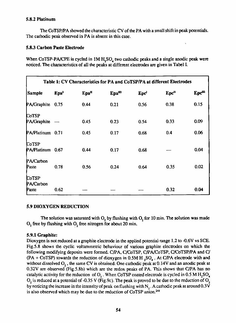
5.8.2 Platinum
The CoTSPIP A showed the characteristic CV of the PA with a small shift in peak potentials. The cathodic peak observed in PA is absent in this case.
5.8.3 Carbon Paste Electrode
When CoTSP-PNCPE is cycled in IM HzSO .. two cathodic peaks and a single anodic peak were noticed. The characteristics of all the peaks at different electrodes are given in Tabel I.
Table 1: CV Characteristics for PA and CoTSP/PA at different Electrodes
Sample EpaI EpaD Epam EpcI EpcD EpcID
PNGraphite 0.75 0.44 0.21 0.56 0.38 0.15
~TSP PNGraphite 0.45 0.23 0.54 0.33 0.09
P AlPlatinum 0.71 0.45 0.17 0.68 0.4 0.06
CoTSP P AlPlatinum 0.67 0.44 0.17 0.68 0.04
PNCarbon Paste 0.78 0.56 0.24 0.64 0.35 0.02
CoTSP PNCarbon Paste 0.62 0.32 0.04
5.9 DIOXYGEN REDUCTION
The solution was saturated with 02 by flushing with 02 for 10 min. The solution was made 02 free by flushing with 02 free nitrogen for about 20 min.
5.9.1 Graphite: Dioxygen is not reduced at a graphite electrode in the applied potential range 1.2 to -0.6V vs SCE. Fig.5.8 shows the cyclic voltammetric behaviour of various graphite electrodes on which the following modifying deposits were formed. C/PA, C/CoTSP, ClPNCoTSP. ClCoTSP/PA and Cl (PA + CoTSP) towards the reduction of dioxygen in 0.5M H 2S0 ... At ClPA electrode with and without dissolved 02 ' the same CV is obtained. One cathodic peak at O.14V and an anodic peak at O.32V are observed (Fig.5.8b) which are the redox peaks of PA. This shows that ClPA has no catalytic activity for the reduction of °2, When CoTSP coated electrode is cycled in 0.5 M ~SO .. 02 is reduced at a potential of -0.35 V (Fig.9c). The peak: is proved to be due to the reduction of 02 by noticing the increase in the intensity of peak on flushing with N2 . A cathodic peak at around O.3V is also observed which may be due to the reduction of CoTSP anion.248
54
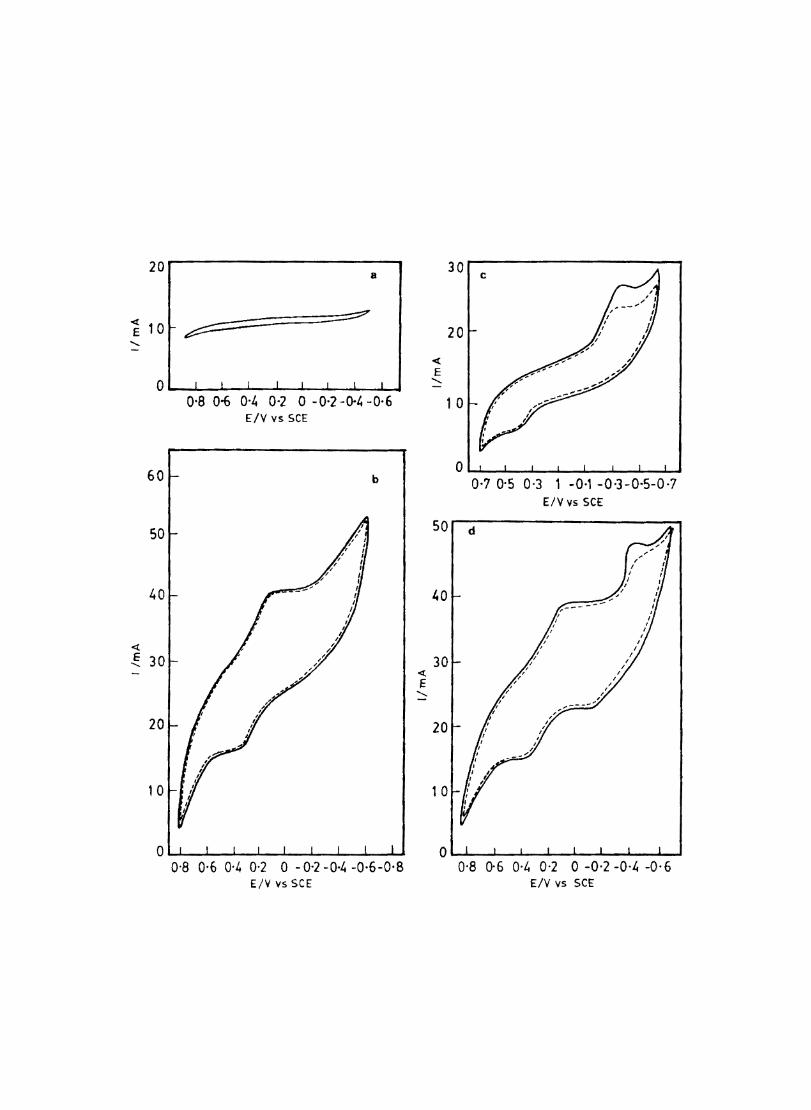
20
<{
E 10 .....
0
60
50
40
« ~ 30
20
1 0
a
~ ~
0'8 0-6 0-4 0-2 o -0-2 -(}4 -0-6 EIV vs SCE
b
0'8 0·6 0·4 0-2 0 - 0-2 -0,4 -0-6-0'8 Elv vs SCE
30
20
<{
E .....
1 0
0-7 0-5 0-3 1 -0-' -0-3-0·5-0·7 EIV vS SCE
50r---------------------~
1.0
30
20
1 0
0-8 0-6 0'" 0'2 0 -0-2 -0-" -0- 6 EIV vs SCE
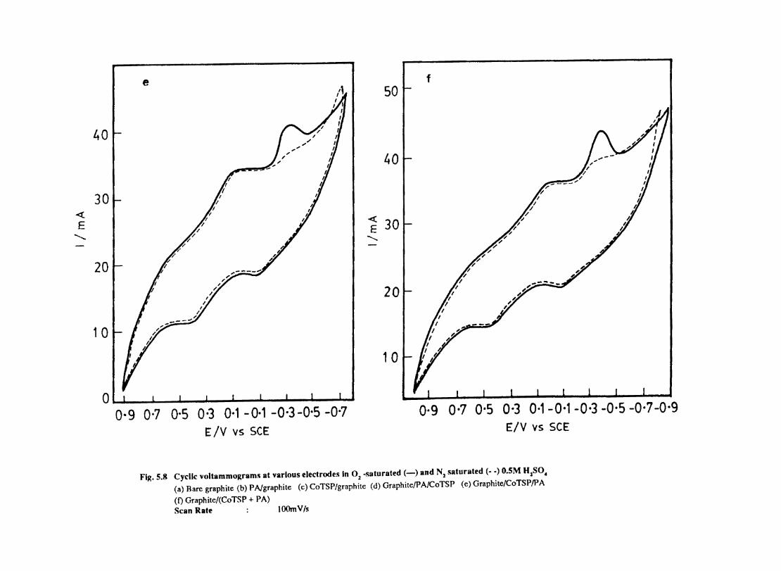
<t E
........
e - I f 50
I "....". AI 40
I I """ f/ 40
I r' I I 30
/ / ~ 30 ........ -
20 I I ~~
20
I /'_J 10
I / i' 1 0
01 r I I O·g 0-7 0-5 0-3 0·1-0·1 -0·3 -0-5 -0,7 -O·g O·g 0'7 0-5 0'3 0·1 - 0·1 -0-3 -0·5 -0-7
Ely vs SCE ElY vs SCE
Flg.5.8 Cyclic voltammograms at various electrodes In 0: -saturated (-) and Nl saturated (- .) O.5M HzSO, (a) Rare graphite (b) PNgraphile (c) CoTSP/graphite (d) Graphile/PA/CoTSP (c) Graphite/CoTSP/PA
(t) Graphile/(CoTSP + PA) Scan Rate lOOmV/s
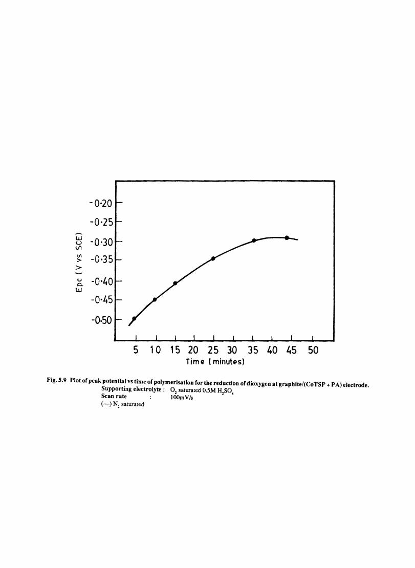
w u 1Il
III > > u 0-w
-0·20
-0,25
-0,30
-0·35
-0-40
-0·45
-0·50
5 10 15 20 25 30 35 40 45 Tim e (minutes)
Fig.5.9 Plot of peak potential vs time ofpol)'merlsation for the reduction ofdioxygen at graphite/(CoTSP + PA) electrode. Supporting electrolyte: 02 saturated O.5M H2SO. Scan rate lOOmV/s (-) N2 saturated
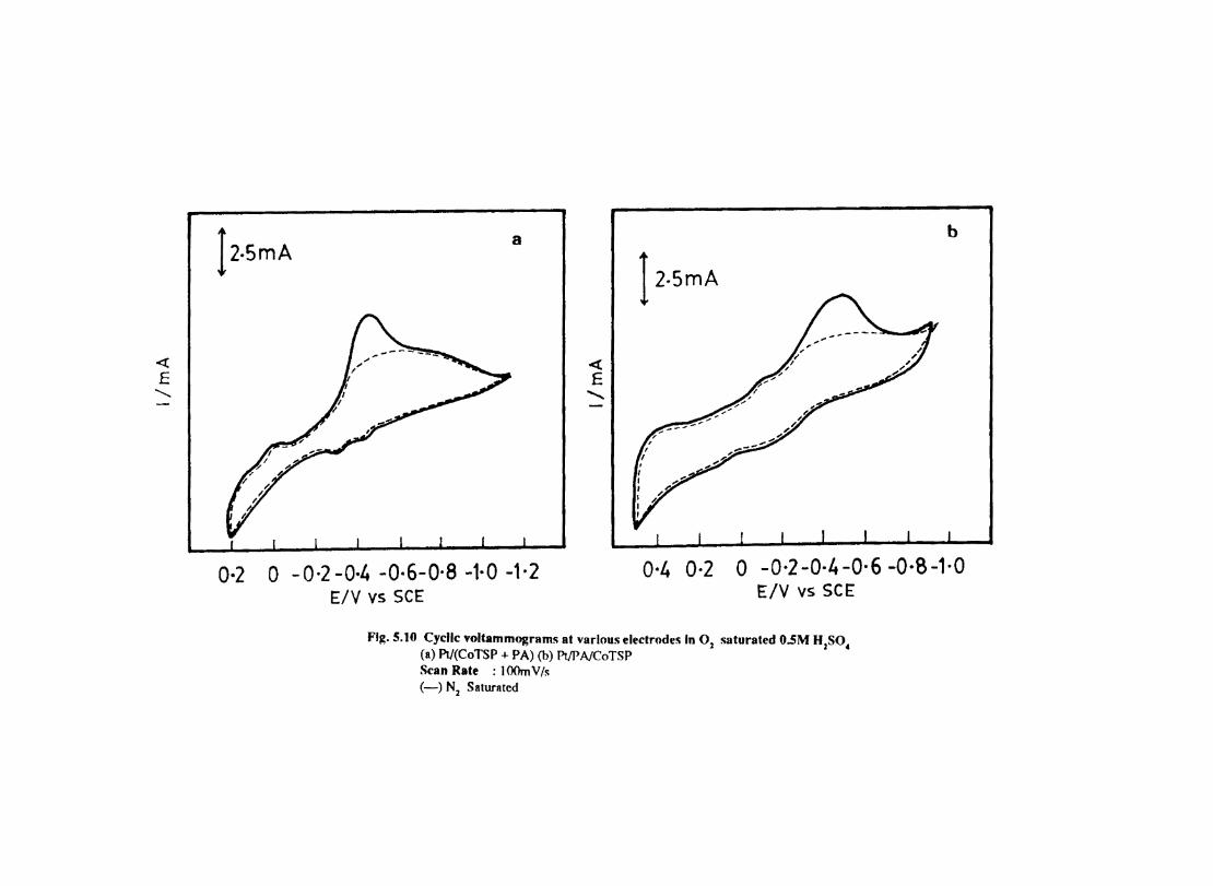
<t: E
.........
12.5mA a
0·2 0 -0·2-0·4 -0·6-0·8 -1·0 -1·2 E/V vS SCE
<! E
.......
b
I2.5mA
0·4 0·2 0 -0·2 -0·4 -0·6 -O·S -1·0 E/V vs SCE
Fig. 5.10 Cyclic voltammograms at various electrodes In 0l saturated O.5M HzSO. (a) PtI(CoTSP + PA) (b) PtlPNCoTSP Scan Rate : lOOmV/s (-) Nz Saturated
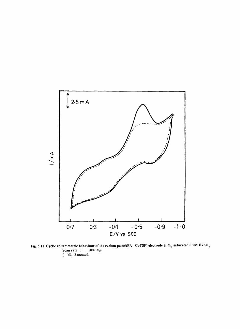
« E
..........
!2osmA
0·7 0-3 -0-1 -0-5 -o·g -1· 0 E/V vs SCE
Fig. 5.11 Cyclic voltammetric behaviour of the carbon past.e/(PA +CoTSP) electrode in 02 saturated O.SM H1S0& Scan rate: lOOmV/s (-)Nz Saturated.
also a catalytic wave for 02 reduction was observed but at a higher negative potential which is perhaps due to the resistance of the PA film for the smooth transfer of electrons. The peak current also decreases substanially. A cathodic peak at - -O.3V ;is also noticed in the case of CoTSP/PA electrode. 02 is reduced at a potential of -0.43V Fig. 5.8e gives the cyclic voltammogram of ClCoTSP/PA. Compared toC/PNCoTSP, this electrode is more sensitive to 02 reduction, gives a higher cathodic current at a less negative potential. The electrocatalytic activity is the greatest with CI(PA+CoTSP). In addition to the 02 reduction peak, a redox peak of PA and an anodic peak of CoTSP are also observed.
The dependence of peak potential for the 02 reduction on the time given for polymerization of (p A +CoTSP) electrode is shown in Fig.5. 9. The electtocatal ytic activity increasing with increase in thickness but only upto a certain thickness beyond which the activity is independent of film thickness.
5.9.2 At platinum
Dioxygen is reduced (Fig.5.1O) at Pt(CoTSP + PA) but at a higher negative potential compared to on graphite/(CoTSP + PA) is required. PtlPN(CoTSP)reduces 02 but the potential shifts to a move negative side i.e. ~ 0.49V. When a film of PA is deposited on this electrode the 02 reduction in inhibited. Both PtI(pA + CoTSP) and PtI(PNCoTSP) give the 02 reduction peak only at pH < 3.
5.9.3 Chemically Prepared CoTSP Doped PolyanilineJCarbon Paste Electrode
Though chemically prepared polyaniline is active in PH < 3, this electrode does not give any catalytic peak for 02 reduction. Another interesting aspect is that when the carbon paste electrode is cycled in a solution containing (p A + CoTSP) washed with distilled water and again cycled in IMKOH, gives a peak for ° reduction with a peak potential of -O.52V (Fig. 5.11)
5.10 Conclusions
The CoTSP anioo can be cooveniently doped into PA film electrochemically by galvanostatically polymerising aniline in dil. ~S04 medium containg CoTSP. It is seen that the CoTSP doped into the PA film remains in the mm even after a number of potential cyclings. Of the different electrodes prepared, CI(CoTSP + PA) showed the highest catalytic activity. The activity for the reduction of 02 at different electrodes are in the following order. CI(PA +CoTSP)>C/CoTSP/P A>ClCoTSP> PtI(PA+CoTSP) = ClPN CoTSP>Pt/Pa/CoTSP > C Paste (PA + CoTSP).
The potential for 02 reduction in the case of CI(PA + CoTSP) is increased with increase in thickness of the PA film. The stability of electroactivity of this electrode is greater than that of C/CoTSP electrode. At (pA +CoTSP) electrode it is likely that the catalytically active centres exist in a multimolecular layer. This is because as the thickness of the PA film increases the availability of active centres for the CoTSP incorporation increases and hence the catalytic activity. Since PA is a moderately conducting polymer, its conductivity in contact with a solution depends on the conditions in the medium.
55
5.11 Mediation of Electron Transfer By (CoTSP) Incorporated Into Poly 0-Toluidine
The concept of controlling the course of an electrochemical reaction by altering the chemical structure of an electrode surface has been worked out by many researchers since 1973 246-:MI. The main attraction of this concept is that the chemical nature of the electrode can be designed in such way as to facilitate the desired electrochemical reduction. The properties and structure of the electrochemically prepared polymer fllms depend on the experimental conditions such as electrode material pH of the medium. nature of supporting electrolyte. time for polymerization. temperature etc. Desired electrochemical properties can be imparted to such polymers by incorporating other electroactive species into them 249.
The permeation of electroactive solutes through films of redox polymers and modification of electrode behaviour by the permeated species have been observed 250. The dynamic behaviour of ionic redox species attached to conducting polymer matrices have been studied in detail 251.253. The diffusion of ionic redox species into the polymer and the rate of heterogeneous electron transfer reaction on the film depend on the concentration of the incorporated redox species. This phenomenon is believed to play a critical role in the functioning of phospholipid bilayer membranes. corrosion inhibiting films on metals etc. Transport of charge and solutes through the redox polymer film coated on electrodes is important in electrocatalysis and photoelectrochemistry 254-257.
The ionic polymer films can be used to bind ionic drugs and then its release can be triggered by neutralizing the charge on the polymer 258. For example a neurotransmitter can be ionic ally bound to the polymer backbone of a polymeric electrode surface and it remains there until it is released by a pulse of cathodic current 259.
The redox couples incorporated into polymer and polyelectrolyte coatings on electrodes exhibit a much wider range of effective diffusion coefficients than they do when they are in olution 260-262. The electron exchange beween the oxidized and reduced forms of a redox couple can contribute significantly to. or can even become the predominant mode of controlling the diffusion of redox species into such coatings.
Poly (o-toluidine). Poly (m-toluidine) and poly(o-ethyl aniline have been recently reported to be synthesized chemically and electrochemically.263. The properties and structure of the electrochemically prepared polymer films depend on the kind of monomer as well as on the experimental conditions such as electrode material. pH of the medium, nature of supporting electrolyte. time for polymerization etc. The incorportion of electroactive cobalt or iron tetrasulophthalocyanine anion into polypyrrole and polyaniline was reponed 264-26S. These films have been used for oxygen reduction catalyzed by anion.
In this section. the behaviour of a (CoTSP) doped poly (o-toluidine) (POT) electrode in presence of ferricyanide/ferrocyanide couple in aqueous media is reponed. The proposed aim is to bring out the role of ionic ally bound redox couple on an ionic polymer in its redox behaviour.
5.12 EXPERIMENTAL
5.12.1 Reagents
0-Toluidine was polymerized onto the platinum electrode from 0.01 M solution of o-toluidine in 2M HC} by cycling the potential between -0.2V and 0.7V vs SCE at a scan rate of 100 mVs - I (Fig. 5.12). The film coated electrode was washed thoroughly with O.IM HCl. The
56
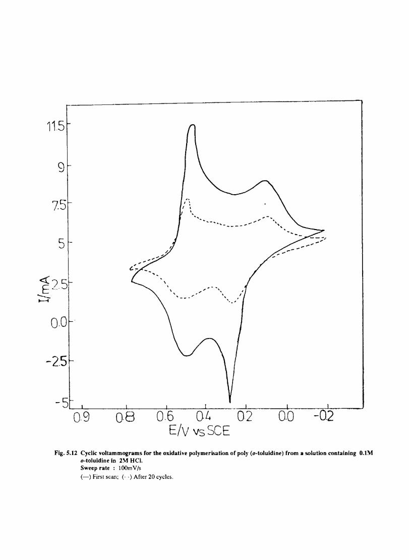
11.5
9
75
5
0.0
-2.5
0·9 0·8
.. I • .
, I \ , '- ........ -...... ..,.. .", ,,-
'----_ ....
0.6 04 0.2 E/V vs SCE
0.0
Fig. 5.12 Cyclic \,oitammograms for the ox.idati"e polymerisation ofpolJ (o-toluldine) from B solution containing O.l~ o-toluldine in 2~ HCI. Sweep rate : lOOm V Is (-) First scan; (- -) After 20 cycles.
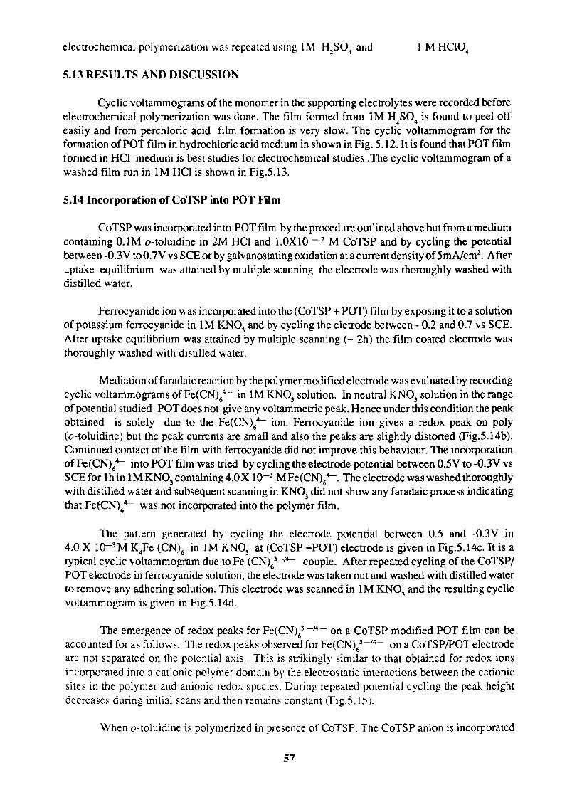
elcctrochcmical polymerization was repeated using I M H2S0
4 and
5.13 RESULTS AND DISCUSSION
Cyclic voltammograms of the monomer in the supponing electrolytes were recorded before electrochemical polymerization was done. The film fonned from 1 M ~S04 is found to peel off easily and from perchloric acid film formation is very slow. The cyclic voltammogram for the formation of POT film in hydrochloric acid medium in shown in Fig. 5.12. It is found that POT film fonned in HCI medium is best studies for electrochemical studies .The cyclic voltammogram of a washed film run in 1 M HCI is shown in Fig.5.13.
5.14 Incorporation of CoTSP into POT Film
CoTSP was incorporated into POT film by the procedure outlined above but from a medium containing O.lM o-toluidine in 2M HCI and 1.0XlO - 2 M CoTSP and by cycling the potential between -0.3V toO.7Vvs SCE or by galvanostatingoxidation at a current density of5mAlcm2
• After uptake equilibrium was attained by multiple scanning the electrode was thoroughly washed with distilled water.
Ferrocyanide ion was incorporated into the (CoTSP + POT) film by exposing it to a solution of potassium ferrocyanide in 1M KN0
3 and by cycling the eletrode between - 0.2 and 0.7 vs SCE.
After uptake equilibrium was attained by multiple scanning (- 2h) the film coated electrode was thoroughly washed with distilled water.
Mediation offaradaic reaction by the polymer modified electrode was evaluated by recording cyclic voltammograms of Fe(CN)/- in IM KN0
3 solution. In neutral KN0
3 solution in the range
of potential studied POT does not give any voltammetric peak. Hence under this condition the peak obtained is solely due to the Fe(CN)64- ion. Ferrocyanide ion gives a redox peak on poly (o-toluidine) but the peak currents are small and also the peaks are slightly distorted (Fig.5.14b). Continued contact of the film with ferrocyanide did not improve this behaviour. The incorporation of Fe(CN)64- into POT film was tried by cycling the electrode potential between 0.5V to -O.3V vs SCE for Ihin 1MKN0
3 containing4.0X 10-3 MFe(CN)64-. The electrode was washed thoroughly
with distilled water and subsequent scanning in KN03
did not show any faradaic process indicating that Fe~CN)64- was not incorporated into the polymer film.
The pattern generated by cycling the electrode potential between 0.5 and -O.3V in 4.0 X 10⁻³ M K4Fe (CN)6 in IM KN0
3 at (CoTSP +POT) electrode is given in Fig.5.14c. It is a
typical cyclic voltammogram due to Fe (CN)63-14-- couple. After repeated cycling of the CoTSP/ POT electrode in ferrocyanide solution, the electrode was taken out and washed with distilled water to remove any adhering solution. This electrode was scanned in IM KN0
3 and the resulting cyclic
voltammogram is given in Fig.5.14d.
The emergence of redox peaks for Fe(CN)/ -/4 - on a CoTSP modified POT film can be accounted for as follows. The redox peaks observed for Fe(CN)/-/4- on a CoTSP/POT electrode are not separated on the potential axis. This is strikingly similar to that obtained for redox ions incorporated into a cationic polymer domain by the electrostatic interactions between the cationic sites in the polymer and anionic redox species. During repeated potential cycling the peak height decreases during initial scans and then remains constant (Fig.5.15).
\Vhen o-toluidine is polymerized in presence of CoTSP, The CoTSP anion is incorporated
57
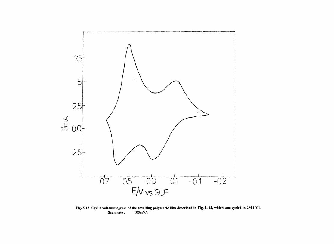
_ ... -------..
7S
5
2.5
« E ~ 0.0
-25i . \./
L_-.L---..._ .. _ ~ _ .. __ 1__ I ____ '-_ _
0'7- ---0.-5- 0·3 01 -0·1 -0:2
E/v vs SCE
Fig. 5.13 Cyclic voltammogram of the resulting polymeric mm described in Fig. S. 12, which was cycled In lM HCL Scan rate: lOOmV/s
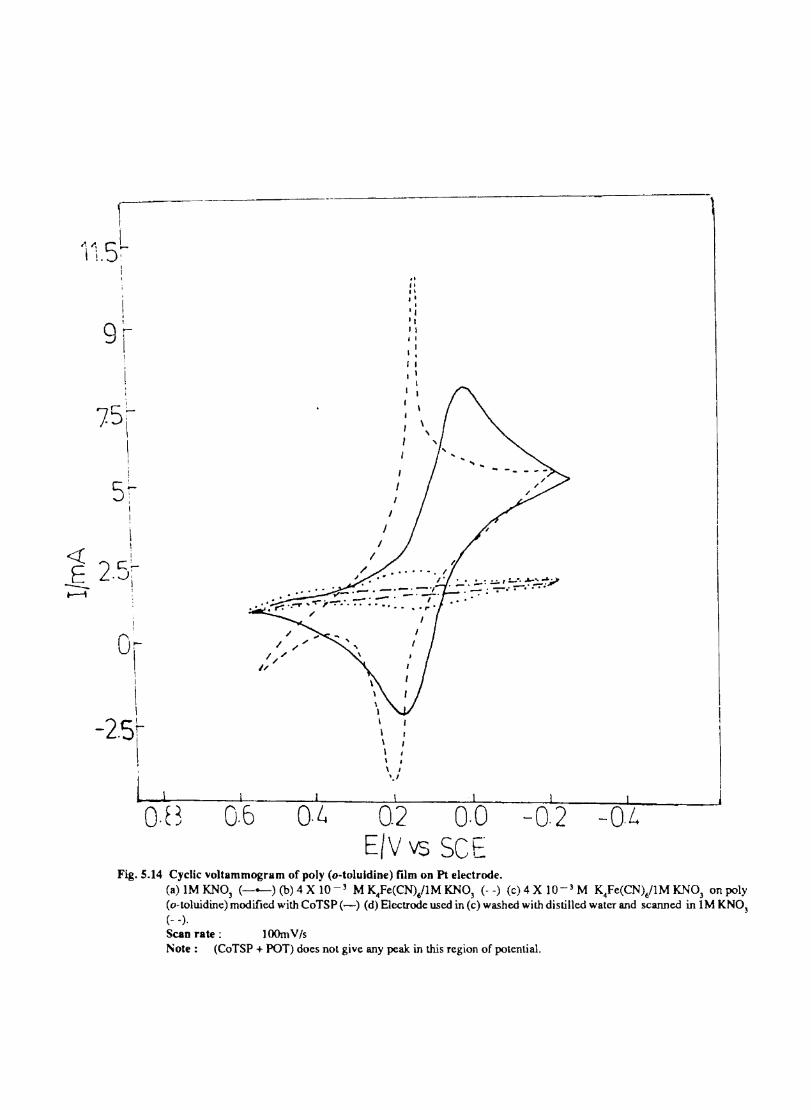
~ !
"", SL i I '
Sf
0: I ! I
\ I
-2.5r \
l 0·(3 0·6 O·G
\ . \ I
'.I
" .. " , ' , 'I 'I 11 • I
1 , . I1 , I
I
I
\
\
0.2 0·0 E/V vs SCF
-0.2 -O.L
Fig. 5.14 Cyclic voltammogram of poly (o-toluldine) film on Pt electrode. (a) IM KNO] (--) (b) 4 X 10 -3 M K~Fe(CN)/IM KNO) (- -) Cc) 4 X 10-- 3 M K~Fe(CNVIM KNO) on poly (o-toluidine) modified with CoTSP(-) (d) Electrode used in Cc) washed wilb distilled water and scanned in IM KN03
(- -). Scan rate: lOOm V Is Note: (CoTSP + POT) does not give any peak in this region of potential.
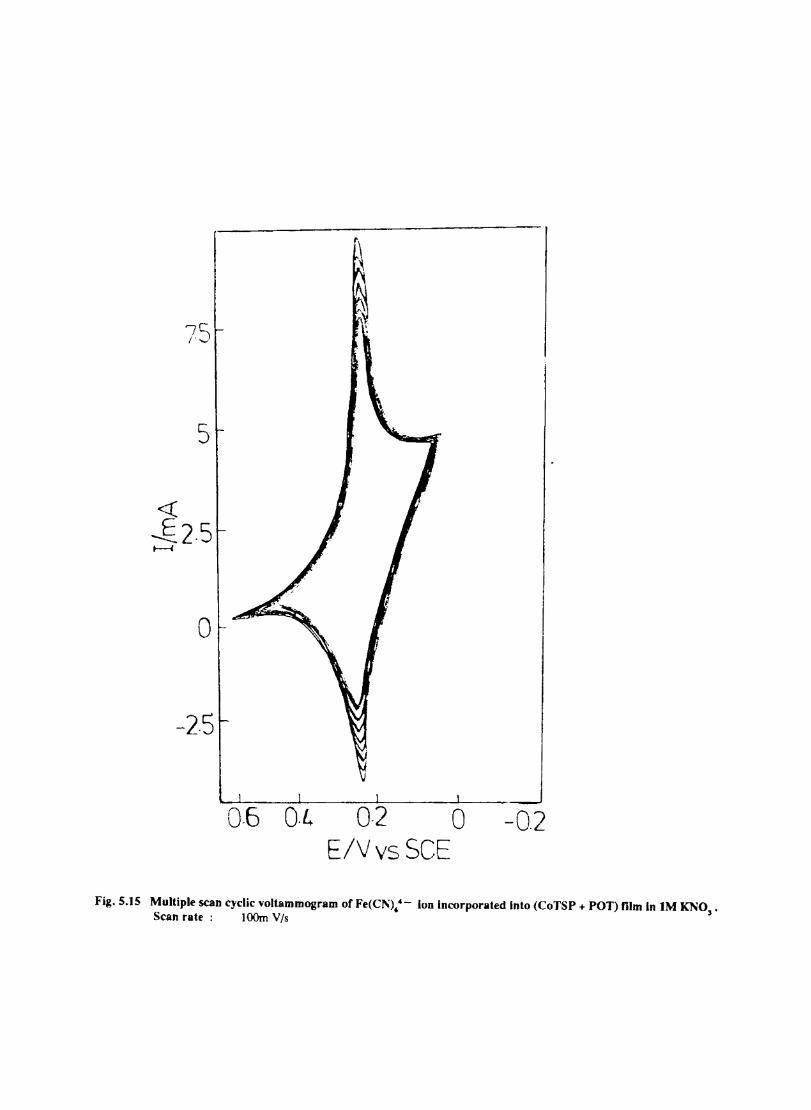
7S
5
o
-2.5
I.-.....l..-----------I::~-~ 0·6 0·4 0·2 0 -0.2
E/Vys SCE
Fig.5.15 Multiple scan cyclic voltammogram of Fe(CJ\): - Ion Incorporated Into (CoTSP + POT) film In IM KNO,. Scan rate : lOOm Vis
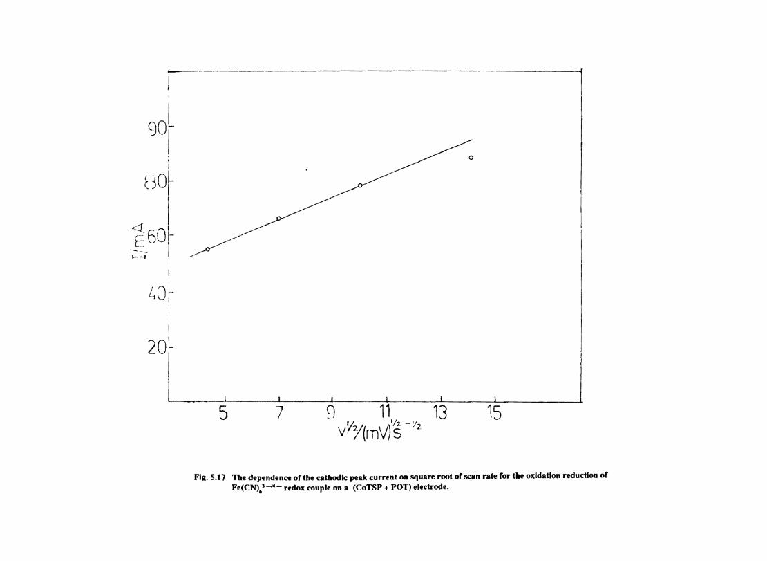
r-----I -
90r I , i
F -'O~ ~)
<:1 E60 --. I--i
LIO
20
~
5 9 11. 13 vYY(mV) S -Y2
15 7
FI~. 5.17 The dependence of the cathodic peak current on square root of scan rate for the oxidation reduction of Fe(CN),'-- redox couple on a (CoTSP + POT) electrode.
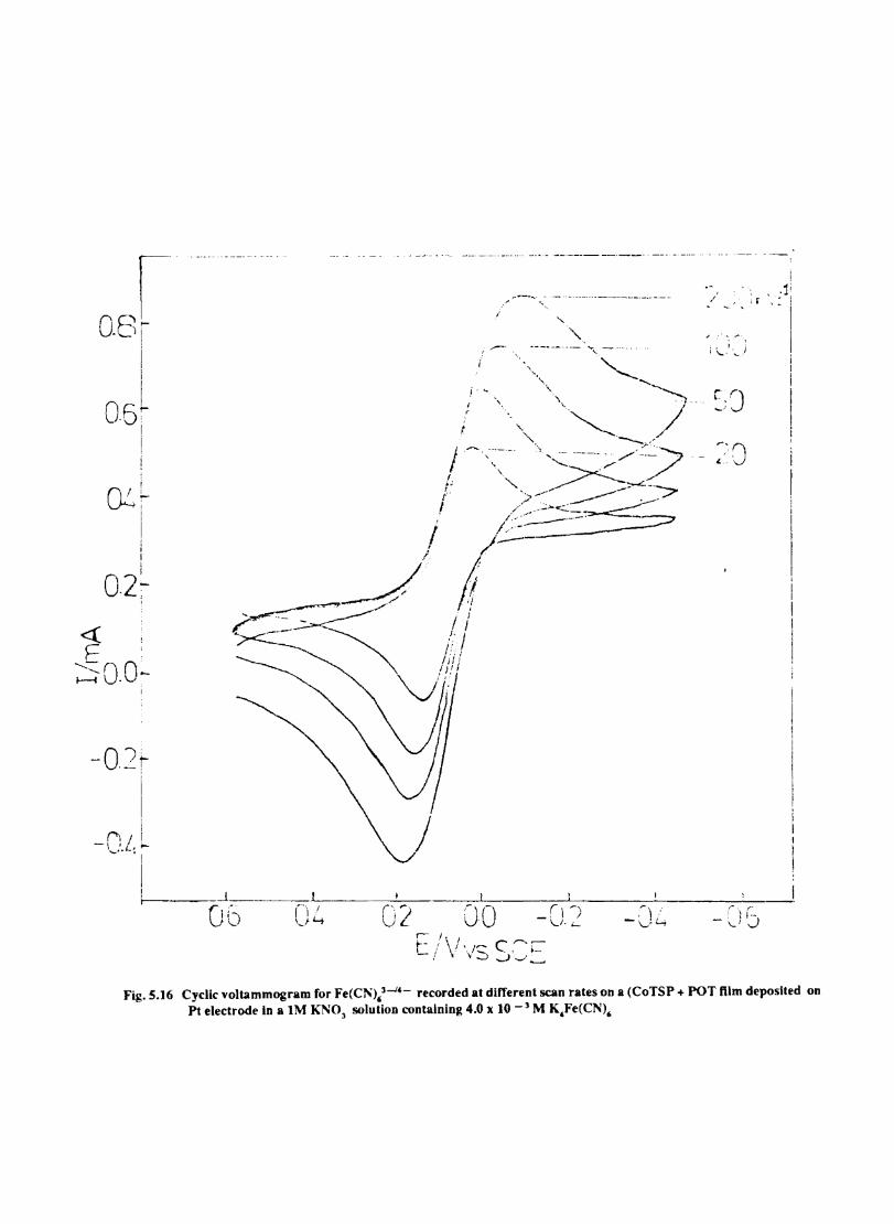
(1! L U'-' I
i i !
O,2~ ,
-o./~
I , r'1 i -IIL.;-
,-" '[ i-____ J
06 ('j ') Vi...
,
I I
I , I'~ I
t
i .---.
l
j . ~.
I r
~'"
00
.. ---........ - ..•. _-_ .... _---_._.-.. -._-
-", ..
~-~---.-~- '" '.
'.
rI' - \ .. ) l-f
.I' ." '. .~',
i \.. I J
r.'J L- " .... .,.!
Fig.5.16 Cyclic voltammogram for Fe(C1"),3.....J'- recorded at different scan rates on a (CoTSP + POT ftlm deposited on Pt electrode In a IM KNO] solution contalnlng 4.0 x 10 -] M K,Fe(CN)6
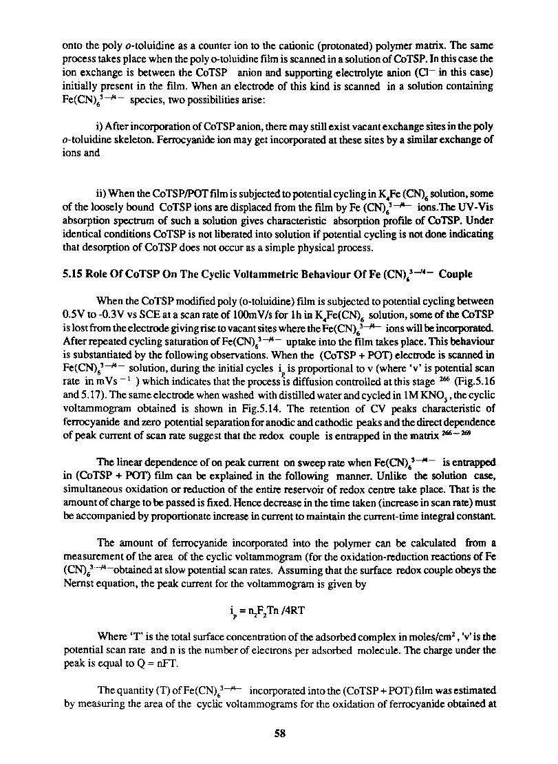
onto the poly o-toluidine as a counter ion to the cationic (protonated) polymer matrix. The same process takes place when the poly o-toluidine film is scanned in a solution of CoTSP. In this case the ion exchange is between the CoTSP anion and supporting electrolyte anion (Cl- in this case) initially present in the film. When an electrode of this kind is scanned in a solution containing Fe(CN)63 ---J4- species, two possibilities arise:
i) After incorporation of CoTSP anion, there may still exist vacant exchange sites in the poly o-toluidine skeleton. Ferrocyanide ion may get incorporated at these sites by a similar exchange of ions and
ii) When the CoTSPIPOT film is subjected to potential cycling in K4Fe (eN)6 solution, some of the loosely bound CoTSP ions are displaced from the film by Fe (CN),3 -14-- ions. The UV -Vis absorption spectrum of such a solution gives characteristic absorption proftle of CoTSP. Under identical conditions CoTSP is not liberated into solution if potential cycling is not done indicating that de sorption of CoTSP does not occur as a simple physical process.
5.15 Role OfCoTSP On The Cyclic Voltammetric Behaviour Of Fe (CN),3-14- Couple
When the CoTSP modified poly (o-toluidine) film is subjected to potential cycling between O.5V to -O.3V vs SCE at a scan rate of lOOm V Is for lh in K4Fe(CN)6 solution, some of the CoTSP is lost from the electrode giving rise to vacant sites where the Fe(CN)t--14- ions will be incorporated. After repeated cycling saturation of Fe(CN)t---I4- uptake into the film takes place. This behaviour is substantiated by the following observations. When the (CoTSP + POT) electrode is scanned in Fe(CN)63 ---J4- solution, during the initial cycles ip is proportional to v (where 'v' is potential scan rate in mVs -I ) which indicates that the process is diffusion controlled at this stage 266 (Fig.5.16 and 5.17). The same electrode when washed with distilled water and cycled in IM KN03 , the cyclic voltammogram obtained is shown in Fig.5.14. The retention of CV peaks characteristic of ferrocyanide and zero potential separation for anodic and cathodic peaks and the direct dependence of peak current of scan rate suggest that the redox couple is entrapped in the matrix 266-269
The linear dependence of on peak current on sweep rate when Fe(CN)63---14- is entrapped in (CoTSP + POT) fllm can be explained in the following manner. Unlike the solution case, simultaneous oxidation or reduction of the entire reservoir of redox centre take place. That is the amount of charge to be passed is fixed. Hence decrease in the time taken (increase in scan rate) must be accompanied by proportionate increase in current to maintain the current-time integral constant.
The amount of ferrocyanide incorporated into the polymer can be calculated from a measurement of the area of the cyclic voltammogram (for the oxidation-reduction reactions of Fe (CN),3-14-obtained at slow potential scan rates. Assuming that the surface redox couple obeys the Nemst equation, the peak current for the voltammogram is given by
Where 'T' is the total surface concentration of the adsorbed complex in moles/cm2 , 'v' is the
potential scan rate and n is the number of electrons per adsorbed molecule. The charge under the peak is equal to Q = nFT.
The quantity (T) ofFe(CN)63-14- incorporated into the (CoTSP + POT) film was estimated by measuring the area of the cyclic voltammograms for the oxidation of ferrocyanide obtained at
58

slow scan rate.
T value was calculated from the relation
T = i x 4RT I n2p .p b = 1 x 4RT I nF coloum s P
The quantity of Fe(CN)64 - incorporated was found to be 2.98 X 10 -2 m moles/cm2
59
CHAPTER VI
Metal Tetrasulphophthalocyanine As Corrosion Inhibitors
6.1 Introduction
Corrosion is the deterioration of metals by electrochemical or direct chemical reactions and in that sense it is an industry in reverse 271. Corrosion rate is influenced by factors such as nature of the metal, the corrodent, nature of the corrosion product temperature, electrical potential between two metals and the relative velocity of the corrodent with respect to the metal. The relationship among these factors determines the type of corrosion.
All metals except gold are thermodynamically unstable with respect to their oxides. Corrosion represents the tendency of pure metals and alloys to return to thermodynamically stable compounds. The fundamental process of corrosion is the anodic dissolution of the metal to form its ions.
M ---> M+z + ZeM [1]
The ions may be carried away into the bulk of the solution in contact with the metal or may for insoluble compounds which adhere on the metal surface. A layer of oxide or hydroxide may be formed on the surface and this is sometimes further converted to a higher oxide. Such layers may be porous allowing further corrosion (as with iron), or they may be compact and nonporous, forming a protective layer blocking further corrosion (as with aluminium).
When an isolated piece of metal is communicating with a corrosive medium the corrosion reaction represented by equation (1) cannot proceed unless another process takes place at the same rate to carry away the electrons accumulated in the metal. In most cases, spontaneous corrosion is accompanied by hydrogen evolution or oxygen reduction, although other cathodic reactions may serve the same pwpose of consuming the electrons released in the anodic dissolution of the metap72.
Corrosion will be either accelerated or retarded by an applied electric potential by changing the chemical activity of metals relative to each other and to hydrogen. In general, if an applied potentia1lowers the activity of metal below to each other and to hydrogen, corrosion is retarded or stopped and the metal is said to be cathodically protected. Cathodic protection can also be secured by using an external electrode that is more active than the metal being protected..
Active metals such as aluminium, titanium and high chromium (stainless) steel owe their good corrosion resistance under oxidising conditions to surface oxide fllm that is adherent and impervious, though of non oxidizing conditions. When this passive layer is not formed these metals may corrode quite rapidly. The acidity of the corroding medium and whether or not it is aerated also can affect the formation of passive layer.
In the case of spontaneous corrosion, when steady state is reached, the metal attains a constant potential, Ecorr which is termed the mixed potential or corrosion potential. At this potential there is an anodic overpotential,
11 =E -E a corr r,a
driving the metal dissolution process, and a cathodic overpotential 11c= Ecorr - Er,<: driving the
60
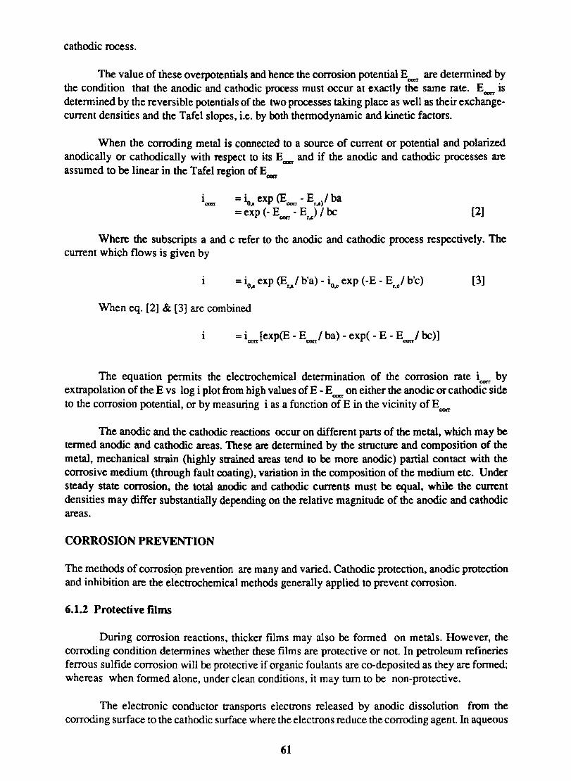
cathodic rocess.
The value of these overpotentials and hence the corrosion potential ECDrT are determined by the condition that the anodic and cathodic process must occur at exactly the same rate. Ec:on- is determined by the reversible potentials of the two processes taking place as well as their exchangecurrent densities and the Tafel slopes, i.e. by both thennodynamic and kinetic factors.
When the corroding metal is connected to a source of current or potential and polarized anodically or cathodic ally with respect to its E.,.,.,. and if the anodic and cathodic processes are assumed to be linear in the Tafel region of Ecorr
= io exp (E - E )/ ba .. corr r ..
= exp (- E - E ) / be con r~ [2]
Where the subscripts a and c refer to the anodic and cathodic process respectively. The current which flows is given by
1 = io exp (E / b'a) - io exp (-E - E / b'c) .. r.a .c r.c [3]
When eq. [2] & [3] are combined
1 = i [exp(E - E / ba) - exp( - E - E / be)] con c:orr corr
The equation permits the electrochemical determination of the corrosion rate icorr by extrapolation of the E vs log i plot from high values of E - E corr on either the anodic or cathodic side to the corrosion potential, or by measwing i as a function of E in the vicinity of Ecorr
The anodic and the cathodic reactions occur on different parts of the metal, which may be termed anodic and cathodic areas. These are determined by the structure and composition of the metal, mechanical strain (highly strained areas tend to be more anodic) partial contact with the corrosive medium (through fault coating), variation in the composition of the medium etc. Under steady state corrosion, the total anodic and cathodic currents must be equal, while the current densities may differ substantially depending on the relative magnitude of the anodic and cathodic areas.
CORROSION PREVENTION
The methods of corrosion prevention are many and varied. Cathodic protection, anodic protection and inhibition are the electrochemical methods generally applied to prevent corrosion.
6.1.2 Protective films
During corrosion reactions, thicker films may also be formed on metals. However, the corroding condition determines whether these films are protective or not. In petroleum refineries ferrous sulfide corrosion will be protective if organic foulants are co-deposited as they are formed; whereas when formed alone, under clean conditions, it may turn to be non-protective.
The electronic conductor transports electrons released by anodic dissolution from the corroding surface to the cathodic surface where the electrons reduce the corroding agent In aqueous
61
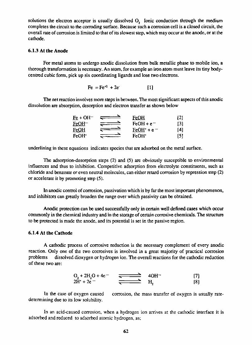
solutions the electron acceptor is usually dissolved O2
Ionic conduction through the medium completes the circuit to the corroding surface. Because such a corrosion cell is a closed circuit, the overall rate of corrosion is limited to that of its slowest step, which may occur at the anode, or at the cathode.
6.1.3 At the Anode
For metal atoms to undergo anodic dissolution from bulk metallic phase to mobile ion. a thorough transformation is necessary. An atom. for example an iron atom must leave its tiny bodycentred cubic form, pick up six coordinating ligands and lose two electrons.
Fe = Fe+1 + 2e- [1]
The net reaction involves more steps in between. The most significant aspects of this anodic dissolution are absorption, desorption and electron transfer as shown below
Fe+OH- ~ FeOH [2] ... FeOH- ~ FeOH+e- [3] '<
FeOH :::.. FeOH+ +e- [4] " FeOH+ ~ FeOH+ [5] '<
underlining in these equations indicates species that are adsorbed on the metal surface.
The adsorption-desorption steps (2) and (5) are obviously susceptible to environmental influences and thus to inhibition. Competitive adsorption from electrolyte constituents, such as chloride and benzoate or even neutral molecules. can either retard corrosion by repression step (2) or accelerate it by promoting step (5).
In anodic control of corrosion, passivation which is by far the most important phenomenon, and inhibitors can greatly broaden the range over which passivity can be obtained.
Anodic protection can be used successfully only in certain well defined cases which occur commonly in the chemical industry and in the storage of certain corrosive chemicals. The structure to be protected is made the anode, and its potential is set in the passive region.
6.1.4 At the Cathode
A cathodic process of corrosive reduction is the necessary complement of every anodic reaction. Only one of the two corrosives is involved in a great majority of practical corrosion problems dissolved dioxygen or hydrogen ion. The overall reactions for the cathodic reduction of these two are:
In the case of oxygen caused determining due to its low solubility.
... , "
[7] [8]
corrosion, the mass transfer of oxygen is usually rate-
In an acid-caused corrosion, when a hydrogen ion arrives at the cathodic interface it is adsorbed and reduced to adsorbed atomic hydrogen, as;
62
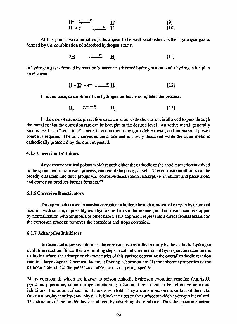
[9] [10]
At this point, two alternative paths appear to be well establIshed. Either hydrogen gas is fonned by the combination of adsorbed hydrogen atoms,
2H [11]
or hydrogen gas is fonned by reaction between an adsorbed hydrogen atom and a hydrogen ion plus an electron
[12]
In either case, desorption of the hydrogen molecule completes the process.
[13]
In the case of cathodic protection an external net cathodic current is allowed to pass through the metal so that the corrosion rate can be brought to the desired level. An active metal, generally zinc is used as a "sacrificial" anode in contact with the corrodable metal, and no external power source is required. The zinc serves as the anode and is slowly dissolved while the other metal is cathodic ally protected by the current passed.
6.1.5 Corrosion Inhibitors
Any electrochemical poison which retards either the cathodic or the anodic reaction invol ved in the spontaneous corrosion process, can retard the process itself. The corrosion inhibitors can be broadly classified into three groups viz., corrosive deactivatiors, adsorptive inhibitors and passivators, and corrosion product-barrier fonners.274
6.1.6 Corrosive Deactivators
This approach is used to combat corrosion in boilers through removal of oxygen by chemical reaction with sulfite, or possibly with hydrazine. In a similar manner, acid corrosion can be stopped by neutralization with ammonia or other bases. This approach represents a direct frontal assault on the corrosion process; removes the corrodent and stops corrosion.
6.1.7 Adsorptive Inhibitors
In deaerated aqueous solutions, the corrosion is controlled mainly by the cathodic hydrogen evolution reaction. Since the rate limiting steps in cathodic reduction of hydrogen ion occur on the cathode surface, the adsorption characteristics of this surface detennine the overall cathodic reaction rate to a large degree. Chemical factors affecting adsorption are (1) the inherent properties of the cathode material (2) the presence or absence of competing species.
Many compounds which are known to poison cathodic hydrogen evolution reaction (e.g.As20 3 pyridine, piperidine, some nitrogen-containing alkaloids) are found to be effective corrosion inhibitors. The action of such inhibitors is two fold. They are adsorbed on the surface of the metal (upto a monolayer or less) and physically block the sites on the surface at which hydrogen is evolved. The structure of the double layer is altered by adsorbing the inhibitor. Thus the specific electron
63
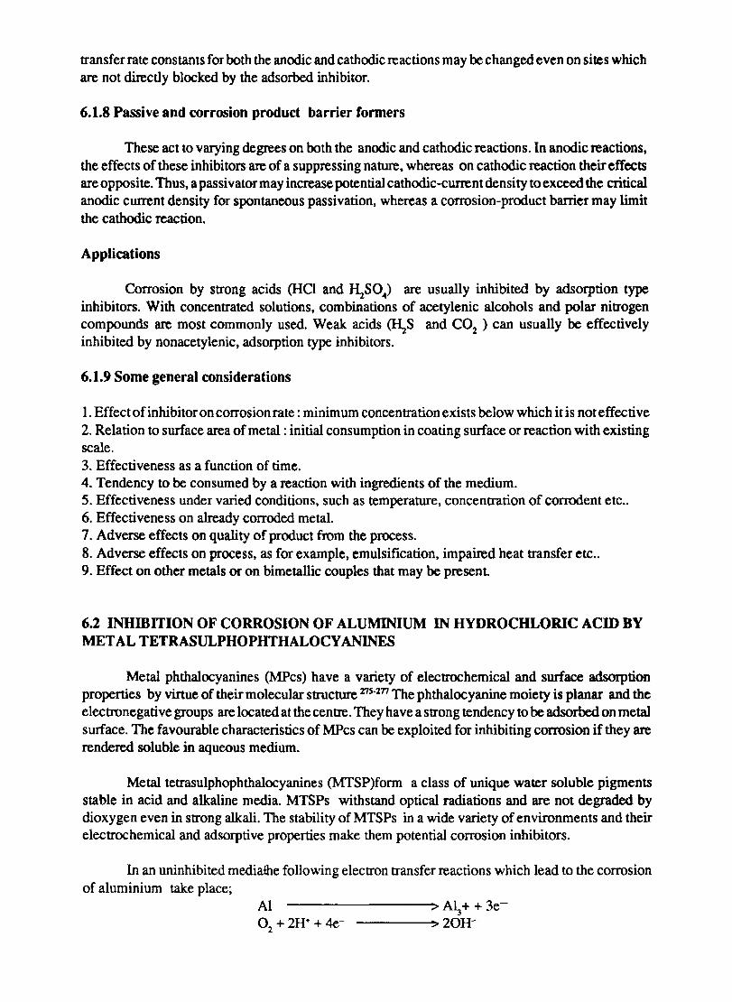
transfer rate constants for both the anodic and cathodic reactions may be changed even on sites which are not directly blocked by the adsorbed inhibitor.
6.1.8 Passive and corrosion product barrier formers
These act to varying degrees on both the anodic and cathodic reactions. In anodic reactions, the effects of these inhibitors are of a suppressing nature, whereas on cathodic reaction their effects are opposite. Thus, a passivator may increase potential cathodic-current density to exceed the critical anodic current density for spontaneous passivation, whereas a corrosion-product barrier may limit the cathodic reaction.
Applications
Corrosion by strong acids (HCI and ~SO .. ) are usually inhibited by adsorption type inhibitors. With concentrated solutions, combinations of acetylenic alcohols and polar nitrogen compounds are most commonly used. Weak acids (l\S and CO2 ) can usually be effectively inhibited by nonacetylenic, adsorption type inhibitors.
6.1.9 Some general considerations
I. Effect of inhibitor on corrosion rate: minimum concentration exists below which it is not effective 2. Relation to surface area of metal: initial consumption in coating surface or reaction with existing scale. 3. Effectiveness as a function of time. 4. Tendency to be consumed by a reaction with ingredients of the medium. 5. Effectiveness under varied conditions, such as temperature, concentration of cornxient etc .. 6. Effectiveness on already corroded metal. 7. Adverse effects on quality of product from the process. 8. Adverse effects on process, as for example, emulsification, impaired heat transfer etc .. 9. Effect on other metals or on bimetallic couples that may be present
6.2 INHmITION OF CORROSION OF ALUMINIUM IN HYDROCHLORIC ACID BY METALTETRASULPHOPHTHALOCY~S
Metal phthalocyanines (MPcs) have a variety of electrochemical and surface adsorption properties by virtue of their molecular structure m·m The phthalocyanine moiety is planar and the electronegative groups are located at the centre. They have a strong tendency to be adsorbed on metal surface. The favourable characteristics of MPcs can be exploited for inhibiting corrosion if they are rendered soluble in aqueous medium.
Metal tetrasulphophthalocyanines (MTSP)form a class of unique water soluble pigments stable in acid and alkaline media. MTSPs withstand optical radiations and are not degraded by dioxygen even in strong alkali. The stability of MTSPs in a wide variety of environments and their electrochemical and adsorptive properties make them potential corrosion inhibitors.
In an uninhibited mediathe following electron transfer reactions which lead to the corrosion of aluminium take place;
Al --------~> A~ + + 3e-o +2H++4e-
2 -----;>20H-
This reaction can be funher enhanced ~ by the presence of species which break the protective oxide layer on aluminium CoTSP is known to catalyse dioxygen reduction and has a tendency to be adsorbed on metal surface. wheras CuTSP is isostructural but its catalytic activity towards O
2 reduction is less. Which one of these conflicting properties does dominate can be
ascertained by evaluating the corrosion inhibition efficiency of these two MTSPS. Advantageous solubility characteristics are found in MTSP and it is wonhwhile to investigate the effect of metal phthalocyanines on the inhibition of aluminium dissolution in HCI medium. Inhibition activity has been measured by weight loss, thermometry, gas evolution and polarization methods and the thermodynamic parameters are reported.
6.2.2 EXPERIMENTAL
Aluminium strips (Indal 2S of the constitution, Si-0.3%, Fe - 0.5%, Ti -0.01 %, B -0.05%, Ga - 0.02% and the rest AI) were used for the studies. The test pieces were polished with 4/0 grade emery paperdegreased with alkaline solution (l5g/1 N~C03 + 15g/1 N~P04) and washed with a copious amount of distilled water. They were washed with reagent grade acetone and dried by pressing between filter paper folds. A fresh test piece was used for each measurement. CoTSP and CuTSP were prepared and purified by the procedure of Weber and Busch 278. $ Jlutions of different concentrations were prepared from a 10-2 M stock solution in water.
6.2.3 THERMOMETRIC METHOD
The test pieces of aluminium were bent to U shape and put in a reaction vessel which was insulated with foamed polystyrene to prevent heat loss. The temperature of the system was measured using a sensitive mercury thennometer, lower end of which rested on the dome of the metal specimen.
The dissolution of aluminium in hydrochloric acid is considerable at concentrations> 1.5M. Hence 2M Hel containing varying amounts of CoTSP was used as the medium.
6.2.4 WEIGHT LOSS METHOD
The test pieces were prepared as above, weighed, and immersed in 50 ml of test solution at room temperature for a period of 15 minutes. They were then washed with distilled water, dried and weighed.
6.2.5 GASOMETRIC METHOD
The dissolution of aluminium in 2M HC} with and without the inhibitor was studied by the hydrogen evolution method in the temperature range 25° to 45° C. The test pieces were prepared as above. A gasometric reaction vessel of the type shown in fig. 6.1 described by Hassan et a1 210 was used. Temperature was controlled at 0.1 ° C by circulating thennostated water around the reaction vessel.
6.2.6 POLARIZATION STUDIES
Aluminium sheet of size 50X25XO.5 mm was used as the electrode. This was polished cleaned and dried as described above. A coating of wax was applied on the specimen using a mask, thus exposing only a defined area (2 cm2
) to the medium. A platinum sheet was used as auxillary electrode and saturated calomel was used as the reference electrode. Measurements were done in
65
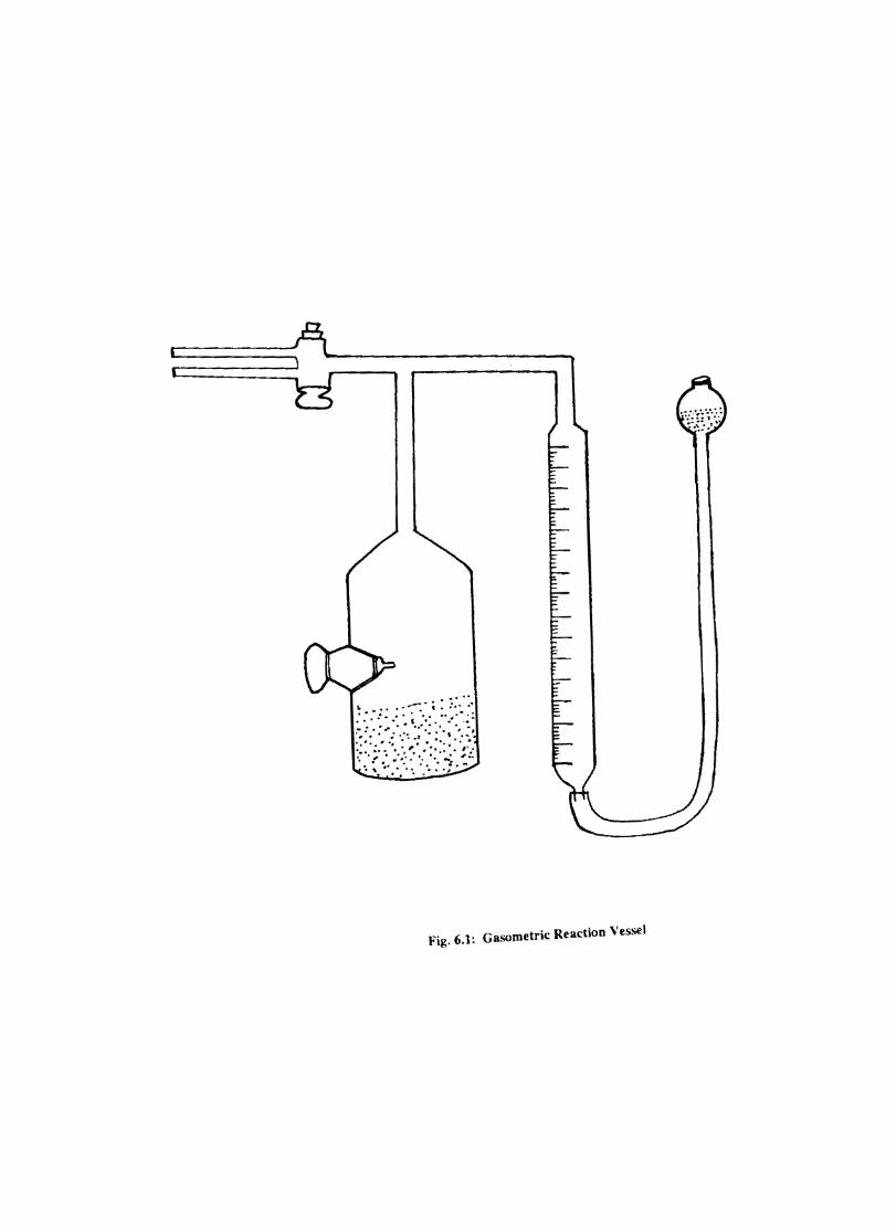
'Fig. 6.1: Gasometric Reaction Ves.o;e\
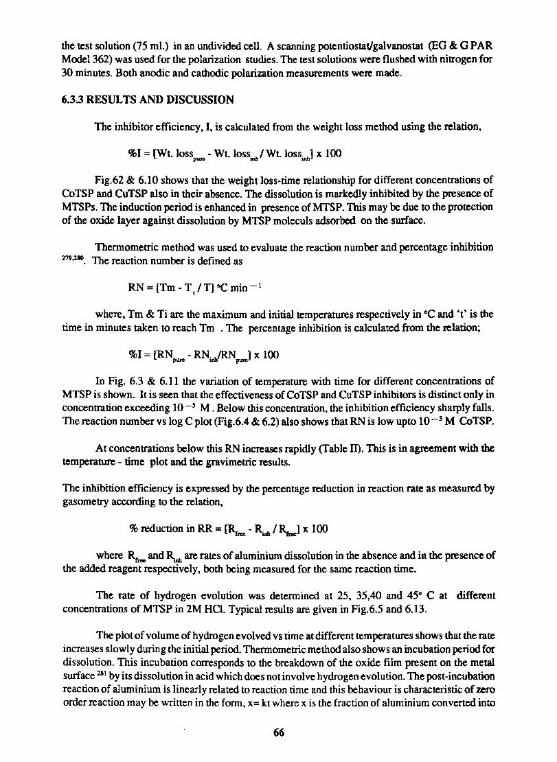
the test solution (75 ml.) in an undivided cell. A scanning potentiostatlgalvanostat (EG & G PAR Model 362) was used for the polarization studies. The test solutions were flushed with nitrogen for 30 minutes. Both anodic and cathodic polarization measurements were made.
6.3.3 RESULTS AND DISCUSSION
The inhibitor efficiency. I. is calculated from the weight loss method using the relation,
%1 = [Wt. 10sspuM • Wt. 10ssinlJ Wt. lossinh] x 100
Fig.62 & 6.10 shows that the weight loss-time relationship for different concentrations of CoTSP and CuTSP also in their absence. The dissolution is markedly inhibited by the presence of MTSPs. The induction period is enhanced in presence of MTSP. This may be due to the protection of the oxide layer against dissolution by MTSP moleculs &lsorbed on the surface.
Thennometric method was used to evaluate the reaction number and percentage inhibition 219,210. The reaction number is defined as
RN = [Tm - T / T] DC min -1 t
where. Tm & Ti are the maximum and initial temperatures respectively in OC and 't' is the time in minutes taken to reach Tm . The percentage inhibition is calculated from the relation;
%1 = [RNpwe - RNuJRN~ x 100
In Fig. 6.3 & 6.11 the variation of temperature with time for different concentrations of MTSP is shown. It is seen that the effectiveness of CoTSP and CuTSP inhibitors is distinct only in concentration exceeding 10-5 M. Below this concentration, the inhibition efficiency sharply falls. The reaction number vs log C plot (Fig.6.4 & 6.2) also shows that RN is low upto 10 -5 M CoTSP.
At concentrations below this RN increases rapidly (Table m. This is in agreement with the temperature - time plot and the gravimetric results.
The inhibition efficiency is expressed by the percentage reduction in reaction rate as measured by gasometry according to the relation.
% reduction in RR = [RbK - RJIIh I ~ x 100
where RbK and RU1h are rates of aluminium dissolution in the absence and in the presence of the added reagent respectively. both being measured for the same reaction time.
The rate of hydrogen evolution was determined at 25, 35.40 and 45° C at different concentrations of MTSP in 2M HCl. Typical results are given in Fig.6.5 and 6.13.
The plot of volume of hydrogen evolved vs time at different temperatures shows that the rate increases slowly during the initial period. Thermometric method also shows an incubation period for dissolution. This incubation corresponds to the breakdown of the oxide film present on the metal surface 211 by its dissolution in acid which does not involve hydrogen evolution. The post-incubation reaction of aluminium is linearly related to reaction time and this behaviour is characteristic of zero order reaction may be written in the form, X= kt where x is the fraction of aluminium converted into
66
101
81
61
r
21
1~~~~~~~--~--~--~--~ 10 20 30 40 50 60 70 80
Time, min.
Fig.6.2: Weight loss-time plot for tbe dissolution of aluminium 10 presence aDd absence of CoTSP; medium 2M HCl. oHC1; lW-BM; clO- 7M; ,)(W-6M; n'W-4M; ~2x.1O-4M
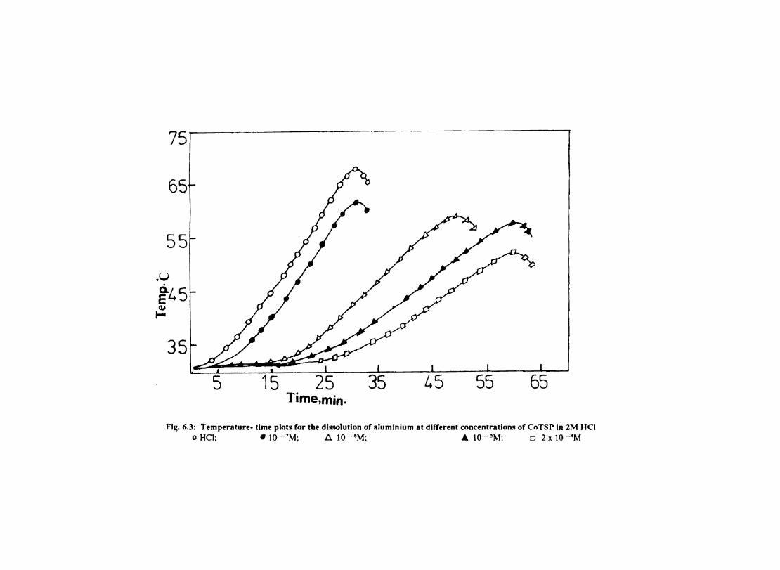
75
65
55
.U
~45 Qi
~
35
5 15 25 35 L.5 55 65 Time,min.
FI~. 6.3: Temperature- time plots for the dls.o;o]utlon of aluminium at different concentrations of CoTSP In 2M HCI o HCI; .10 -7M; A 10 -6M; .. 10 -~M; 0 2 x 10⁻⁴M
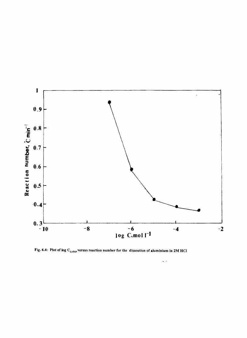
1
0.9
le 0.8 .-f
.U .: 0.7 Cl) .c E ~ c 0.6 c e -Cj 0.5 • ~ =
-0.4
O.3L----------L----------~----------~--------~ -10 -8 -6 -4 -2
log C,moll-1
Fig. 6.4: Plot of log CCoTSP versus reaction number for the dissoution of aluminium in 2M HCI
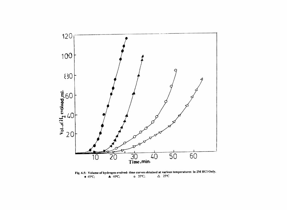
120
100
. -
c30
~60 j (5 , QJ
~L.O '-~ . ~ 20
10 20 30 L.O 50 60 Tirne,min.
Fig. 6.5: Volume of hydrogen evolved- time curves obtained at various temperatures In 2M Hel Only_ • 45"C; A 4O"C; 0 35"C; I::l 25"C
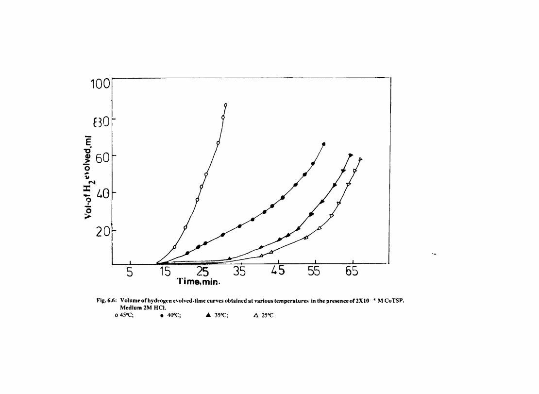
100
l30 -E ~
~ 60 -0 ~ '1J
N
:: 40 9 -~
20
5 25 35 55 65 Time,min.
Fig. 6.6: Volume orhydrogen evolved·time curves obtained at various temperatures In the presence or 2XIO-4 M CoTSP. Medium 2M HCI.
o 45"C; • 4O"C; .. 35"C; 11 25"C
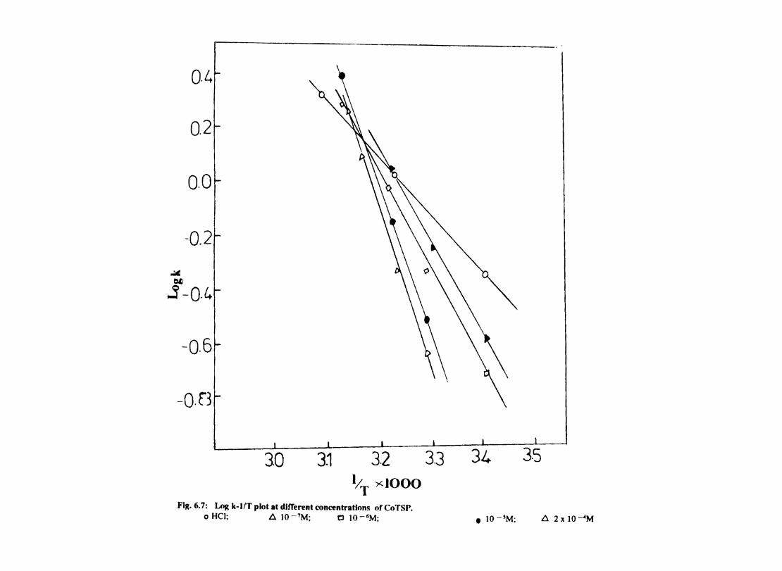
~ ~
0.4
0.2
0.0
-0.2
,j -0·4
-0.6
-0.f3
3.0 3.1 3.2 liT :><1000
Fig. 6.7: Log k-l/T plot at dllTerent concentrations of CoTSP. o HCI; A 10 -7M; Cl 10 -6M;
3.3 3.5
• IO -'M; fl 2 x IO~M
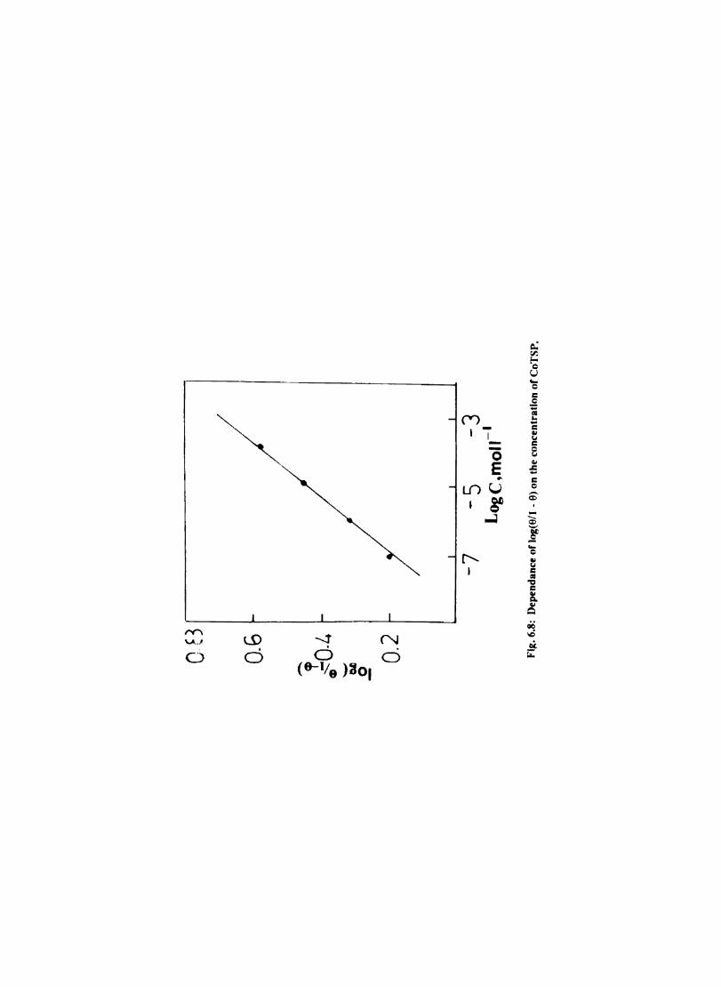
LO . o o
CV> I 1_
£". I
(5 E ..,
.... o c .2 f -c CII ~
e CII
-= c c
-j
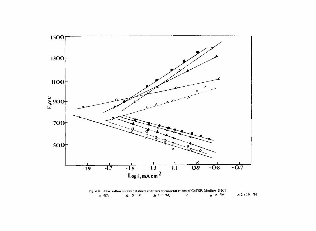
1500
1300
1100
~ E900 ., ~
700
500
x .,...,..---'"
F--
~ --
-1.9 -1.7 -1.5 -1.3 -0·7 Logi, mAcm2
Fig. 6.9: Polarization curves obtained at different concentrations ofCoTSP. Medium 2HCI. o HCI; t::. 1O- 7M; A 10 --fiM; " 0 10 -~M; x 2 x 10 --4M
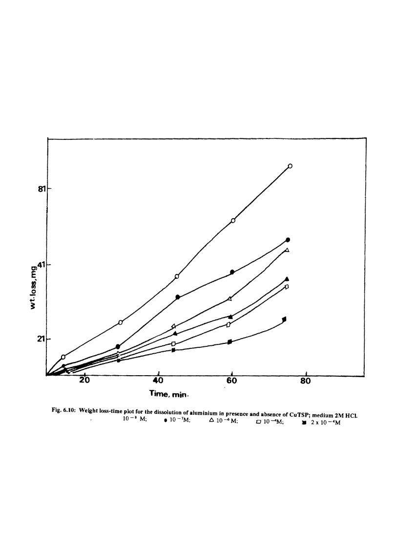
80
Time, min.
Fig.6.10: Weight loss-time plot for the dissolution of aluminium in presence and absence of CuTSPj medium 2M HCI. 10-' M; .1O- 7M; A 10 4 M; DlO-4M; • 2x 1O-4M
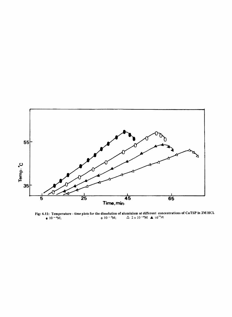
.u c. E t!
55
35
45 Time, min·
65
Fig: 6.11: Temperature - time plots for the dissolution of aluminium at different concentrations of CuTSP in 2M HCI • • 1O- 6M; - olO-5M; !::. 2x lO---<4M £ 10'''1''/
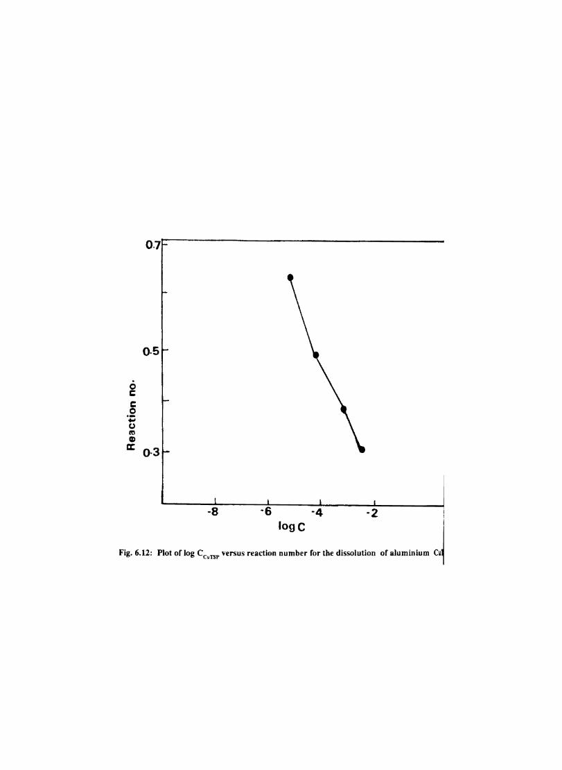
o c c o .-... (.) ft! Cl)
a::
0·5
0·3
-8 -6 -2 lage I
Fig. 6.12: Plot of log CCUTSP versus reaction number for the dissolution of aluminium cu~
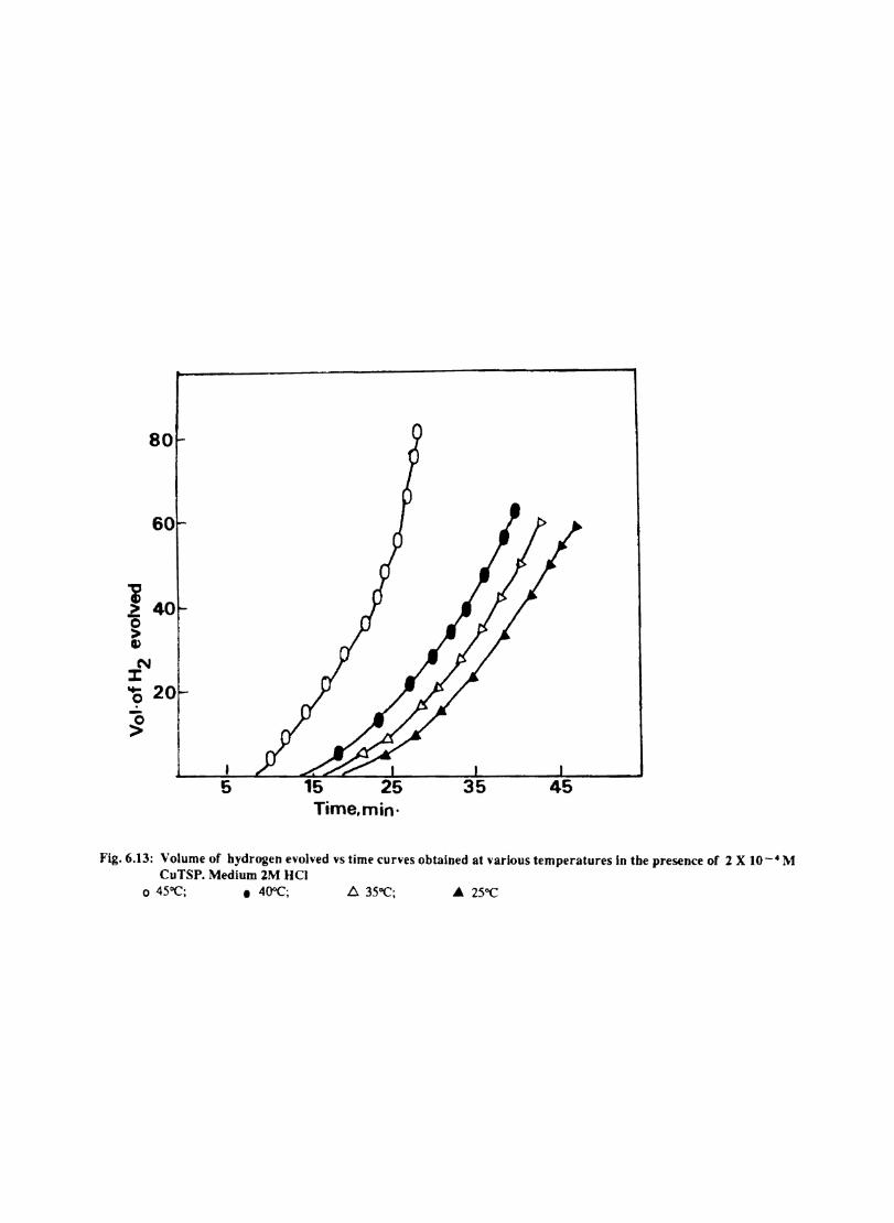
80
60
1 40 0 > 11)
N :I: .... 20 0
~ I 5
Time,min'
Fig.6.13: Volume of hydrogen evolved vs time curves obtained at various temperatures In the presence of 2 X 10- 4 M CuTSP. Medium 2M HCI
o 45"C; • 4O"C; ~ 35"C; • 25"C
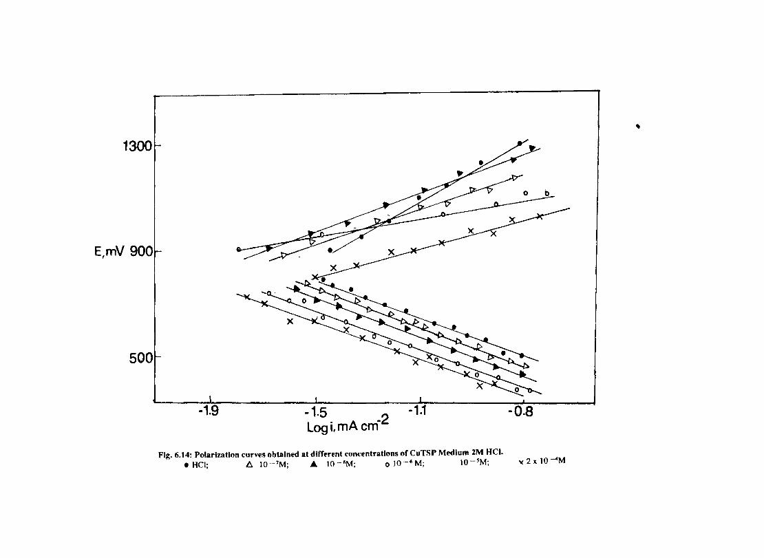
, 1300
E,mV 900
500
-1.9 -1.5 Log if mA cm-2
-1.1 -0.8
Fig. 6.14: Polarization curves obtained at different concentrations of CuTSP Medium 2M HCI. I HCI; II 10 -7M; .& 10 -6M; 0 10 -6 M; 10 --5M; 'I( 2 x 10---4M
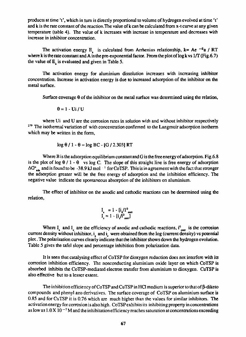
products at time 't', which in turn is directly proportional to volume of hydrogen evolved at time et' and k is the rate constant of the reaction. The value of k can be calculated from x-t curve at any given temperature (table 4). The value of k increases with increase in temperature and decreases with increase in inhibitor concentration.
The activation energy E. is calculated from Arrhenius relationship, k= Ae -Ea I RT where k is the rate constant and A is the pre-exponential factor. From the plot of log k vs 1{f (Fig.6.7) the value of E. is evaluated and given in Table 5.
The activation energy for aluminium dissolution increases with increasing inhibitor concentration. Increase in activation energy is due to increased adsorption of the inhibitor on the metal surface.
Surface coverage e of the inhibitor on the metal surface was determined using the relation,
e = 1- VilV
where Vi and V are the corrosion rates in solution with and without inhibitor respectively 279 The isothermal variation of with concentration confirmed to the Langmuir adsorption isothenn which may be written in the fonn,
log e 11 - e = log BC - [0 /2.303] RT
Where B is the adsorption equilibrium constant and 0 is the free energy of adsorption. Fig.6.8 is the plot of log e / 1 - e vs log C. The slope of this straight line is free energy of adsorption .10°.ds and is found to be -38.9 kJ mol-I for CoTSP. This is in agreement with the fact that stronger the adsorption greater will be the free energy of adsorption and the inhibition efficiency. The negative value indicate the spontaneous absorption of the inhibitors on aluminium.
The effect of inhibitor on the anodic and cathodic reactions can be determined using the relation,
Where I and I are the efficiency of anodic and cathodic reactions, iO is the corrosion • c corr
current density without inhibitor, i. and ic were obtained from the log (current density) vs potential plot. The polarization curves clearly indicate that the inhibitor shows down the hydrogen evolution. Table 5 gives the tafel slope and percentage inhibition from polarization data.
It is seen that catalysing effect of CoTSP for dioxygen reduction does not interfere with its corrosion inhibition efficiency. The nonconducting aluminium oxide layer on which CoTSP is absorbed inhibits the CoTSP-mediated electron transfer from aluminium to dioxygen. CuTSP is also effective but to a lesser extent.
The inhibition efficiency of CoTSP and CuTSP in HCI medium is superior to that of ~diketo compounds and phenyl azo derivatives. The surface coverage of CoTSP on aluminium surface is 0.85 and for CuTSP it is 0.76 which are much higher than the values for similar inhibitors. The activation energy for corrosion is also high. CoTSP exhibits its inhibiting property in concentrations as low as 1.0 X 10 -7 M and the inhibitation efficiency reaches saturation at concentrations exceeding
67

about 2.0 X 10⁻⁴ M. In the case of CuTSP of lowest concentration at which it displays corrosion efficiency is 1.0 X 10⁻⁶ M. Even at lower concentrations it does not accelerate corrosion. Moreover phthalocyanines are non-toxic and well tolerated in living systems 282.
68
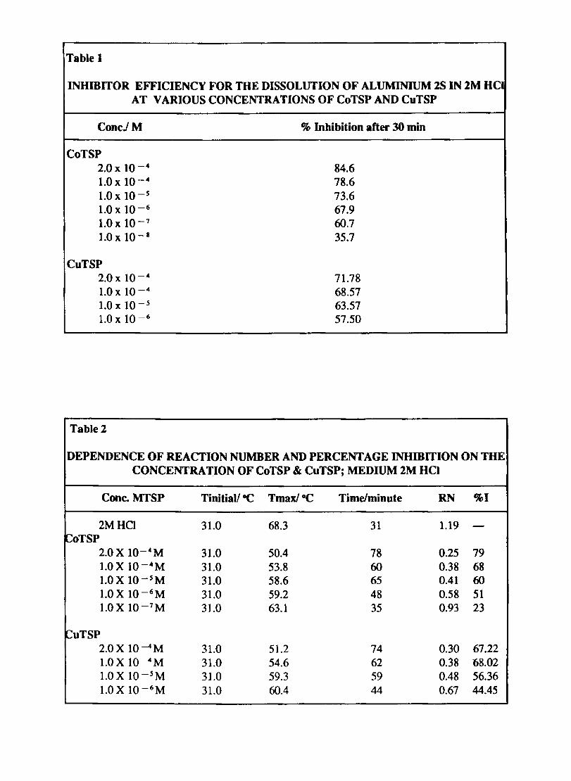
Table 1
INHIBITOR EFFICIENCY FOR THE DISSOLUTION OF ALUMINIUM 2S IN 2M HCI AT VARIOUS CONCENTRATIONS OF CoTSP AND CuTSP
ConcJM % Inhibition after 30 min
CoTSP 2.0 x 10⁻⁴ 84.6 1.0 x 10⁻⁴ 78.6 1.0 x lO-s 73.6 1.0 x 10⁻⁶ 67.9 1.0 x 10⁻⁷ fIJ.7 1.0 x 10⁻⁸ 35.7
CuTSP 2.0 x 10⁻⁴ 71.78 1.0 x 10⁻⁴ 68.57 1.0 x 10⁻⁵ 63.57 1.0 x 10⁻⁶ 57.50
Table 2
DEPENDENCE OF REACTION NUMBER AND PERCENTAGE INHmITION ON THE CONCENTRA lJON OF CoTSP & CuTSP; MEDIUM 2M HCI
Cone. MTSP Tinitiall -C Tmax/°C Time/minute RN %1
2MHCl 31.0 68.3 31 1.19 -~oTSP
2.0 X 1O- 4 M 31.0 50.4 78 0.25 79 l.OX 1O-4 M 31.0 53.8 fIJ 0.38 68 1.0 X 10-sM 31.0 58.6 65 0.41 fIJ 1.0 X 1O-6 M 31.0 59.2 48 0.58 51 l.OX 1O-7 M 31.0 63.1 35 0.93 23
CuTSP 2.0X lO-4M 31.0 51.2 74 0.30 67.22 1.0 X lO-4M 31.0 54.6 62 0.38 68.02 1.0 X lO-sM 31.0 59.3 59 0.48 56.36 l.OX 1O-6M 31.0 60.4 44 0.67 44.45
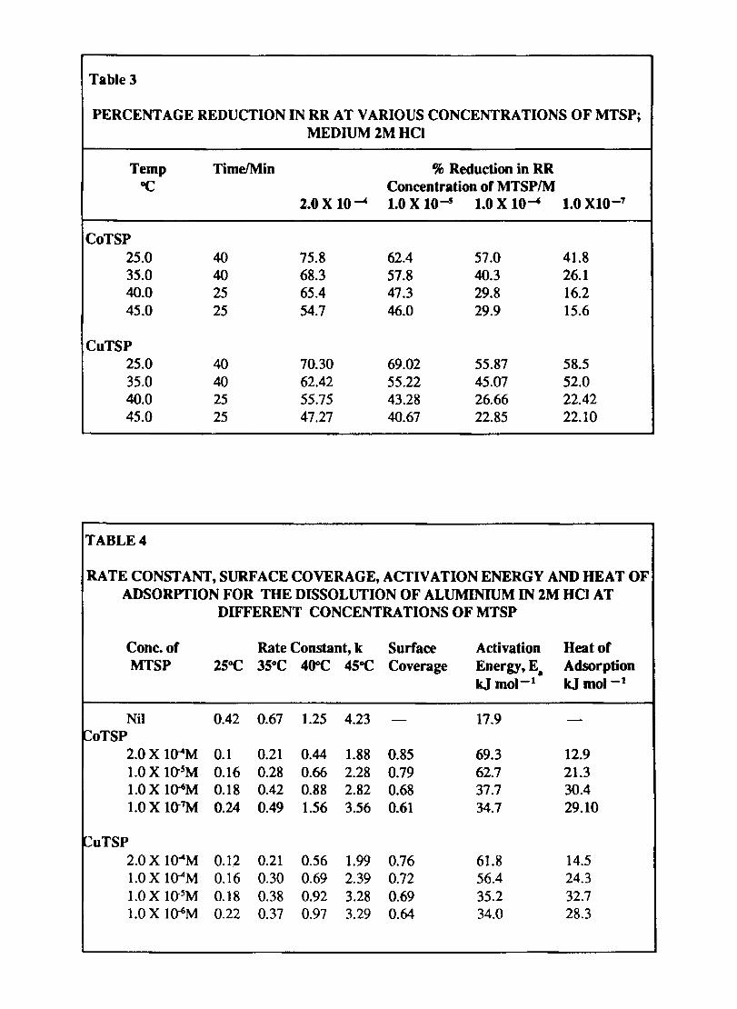
Table 3
PERCENT AGE REDUCTION IN RR AT VARIOUS CONCENTRATIONS OF MTSP; MEDIUM 2M HCI
Temp Time!Min % Reduction in RR ac Concentration of MTSP/M
2.0 X 10~ 1.0 X 10--5 1.0 X 10--4 1.0 XIO-7
CoTSP 25.0 40 75.8 62.4 57.0 41.8 35.0 40 68.3 57.8 40.3 26.1 40.0 25 65.4 47.3 29.8 16.2 45.0 25 54.7 46.0 29.9 15.6
CuTSP 25.0 40 70.30 69.02 55.87 58.5 35.0 40 62.42 55.22 45.07 52.0 40.0 25 55.75 43.28 26.66 22.42 45.0 25 47.27 40.67 22.85 22.10
TABLE 4
RATE CONSTANT, SURFACE COVERAGE, ACTIVATION ENERGY AND HEAT OF ADSORYfION FOR THE DISSOLUTION OF ALUMINIUM IN 2M HCI AT
DIFFERENT CONCENTRATIONS OF MTSP
Cone. of Rate Constant, k Surface Activation Heat of MTSP 2SOC 35°C 400c 4SOC Coverage Energy, E. Adsorption
kJ mol-1 kjmol-1
Nil 0.42 0.67 1.25 4.23 17.9 ~oTSP
2.0 X l(T4M 0.1 0.21 0.44 1.88 0.85 69.3 12.9 1.0 X IO-sM 0.16 0.28 0.66 2.28 0.79 62.7 21.3 1.0 X I~M 0.18 0.42 0.88 2.82 0.68 37.7 30.4 1.0 X Ht7M 0.24 0.49 1.56 3.56 0.61 34.7 29.10
~uTSP 2.0 X l(T4M 0.1.2 0.21 0.56 1.99 0.76 61.8 14.5 1.0 X I~M 0.16 0.30 0.69 2.39 0.72 56.4 24.3 1.0 X IO-5M 0.18 0.38 0.92 3.28 0.69 35.2 32.7 1.0 X l~M 0.22 0.37 0.97 3.29 0.64 34.0 28.3
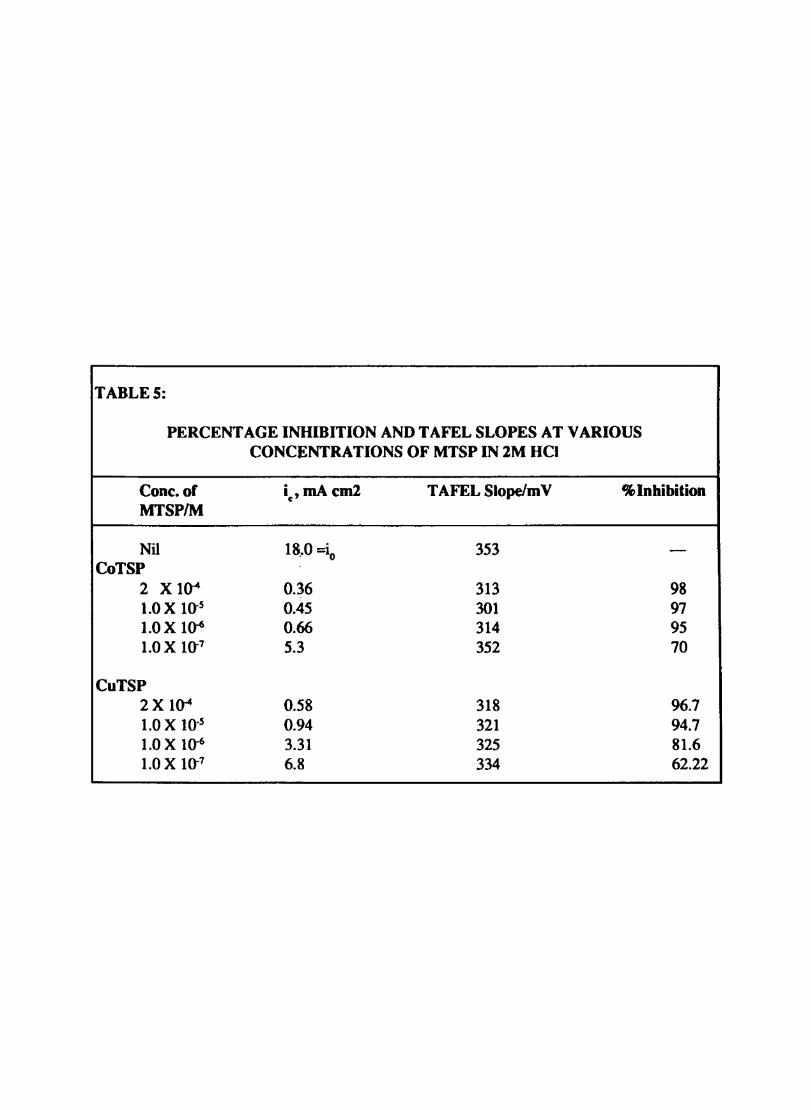
TABLES:
PERCENT AGE INHIBITION AND TAFEL SLOPES AT VARIOUS CONCENTRATIONS OF MTSP IN 2M HCI
Conc.of i ,mAcm2 c TAFEL Slope/m V % Inhibition MTSP/M
Nil 1~.0 =io 353 -CoTSP
2 X 1(}"4 0.36 313 98 1.0 X 10⁻⁵ 0.45 301 97 1.0 X 10.6 0.66 314 95 1.0 X 10⁻⁷ 5.3 352 70
CuTSP 2 X 1(}"4 0.58 318 96.7 1.0 X 10.5 0.94 321 94.7 1.0 X 10⁻⁶ 3.31 325 81.6 1.0 X 10⁻⁷ 6.8 334 62.22
CHAPTER VII SUMMARY AND CONCLUSION
The salient features of the results obtained in this work were discussed in detail in the foregoing sections and are summarised here.
One of the fonnidable obstacles encountered in phthalocyanine chemistry is the separation of singular species for physicochemical studies. Polymorphic forms and molecular aggregates formed by association have varied optical, electrical and electrochemical properties. They show time dependent variation in properties in solution as well as in the solid phase. In addition the elemental analysis is often plagued by deviations which are larger than normal. For the studies reported here, the samples were purified by vacum sublimation and chromatography which give samples with reproducible properties.
Iron phthalocyanine (Fe Pc) and cobalt phthalocyanine (CoPc) catalyse dioxygen reduction and they find application as electrocatalyst in oxygen or air cathode fuel cells. Plasma treatment leads to improved material properties in plasma treatment leads topolymers, surface coatings and catalysts. Effect of low energy plasma treatment on the electroactivity of Co, Fe, Zn and Ni phthalocyanines are reported. Plasma modified materials showed enhanced activity in terms of the lower potential required for the reaction and the higher peak currents observed for cyclic voltammograms. The electrocatalytic activity is further established by comparing the behaviour of standard redox systems like Fe - EDTA, Fe(o-phenanthroline), Fe(CN)64 - , and hydroquinone on modified and unmodified film electrodes. The facile faradaic activity at MPc modified electrode can be explained in terms of the modification of the flat band potentials associated with these. The heterogeneous rate constants for the electrode reaction on the modified electrodes are many orders of magnitude larger than those for unmodified electrodes.
MPcs are p-type semiconductors and the activation energy of the conduction process can be evaluated from the Arrhenius plot of the electrical conductivity versus temperature. Since most of the Pcs undergo polymorphic transitions the method cannot be applied beyond the first phase transition .. Doping ofMPc with iodine leads to enhanced electrical conductivity. Some authors have reported that doping is very similar to a chemisorption and the iodine can be removed by prolonged evacuation. This question has been investigated in detail in this work with reference to CoPe. CoPc was chosen for the study since it has a metal with variable oxidation state at the centre. The magnetic susceptibility, EPR, JR, and the electronic spectra were used to probe the change taking place on the metal ion. The results reveal a change taking place for the central metal atom. DSC was used to see whether iodine is reversibly lost during the heating cycle and to conf'mn whether it modifies the polymorphic transition. It is seen that ~ doped CoPe when subjected to thermal annealing undergoes an irreversible transition and a corresponding exothermic peak is seen in the DSC.
Cyclic voltammograms for the iodine doped and thermally annealed sample in an inert supporting electrolyte give an additional peak which is attributed to the newly generated oxidized fonn of CoPc. Of the thermally annealed metal phthalocyanines CoPc shows maximum activity which is evidenced by the electrode process fordioxygen reduction. FePc andZnPc also give similar results but the activity is much less in these cases.
The study of chemically modified electrodes gives an insight into the mechanism of charge transport through surface species to molecules in solution. The behaviour of cobalt tetrasulphophthalocyanine modified polyaniline and poly (o-toluidine) electrodes were studied. The
69
polyaniline (PA) modified electrode surface was prepared by five different methods and are designated: (i)PA (ii) C!CoTSP/PA (iii)CJPNCoTSPandPt/PNCoTSP (iv) CI(PA + CoTSP) and (v) carbon paste!P A and carbon pasteIP NCoTSP electrodes. These electrodes were electrochemically characterised in acid and alkaline supporting electrolytes by cyclic voltarnmetry. Of the different electodes prepared graphite! (PA + CoTSP) showed the highest activity for the catalytic reduction of dioxygen. Other electrodes also mediate 02 reduction but the reduction occurs only at higher negative potentials. Though the carbon paste/PA and OPA/CoTSP paste electrodes show electrochemical activity at pH < 3. they do not show any catalytic activity.
The mediation of electron transfer by cobalt tetrasulphophthalocyanine ion (CoTSP) incorporated into poly (o-toluidine) POT) was also studied by the same techniques. The CoTSP ion was incorporated into (POT) electrochemically. The mediation of reversible electron transfer by this film was studied. Multiply charged anionic species like ferrocyanide was exchanged on (CoTSP + POT) electrode and are not displaced even after repeated potential cycling.
Tetrasulphoderivatives ofMPcs are among the easily prepared water soluble phthalocyanine derivatives. These are also easily adsorbed on surfaces. Cobalt tetrasulphophthalocyanine (CoTSP) catalyses certain reactions including 02 reduction in solution. The influence of the dual properties. namely. catalysis of02 reduction and adsorption on surfaces on the corrosion of metals is interesting and this was studied. A comparison is made with CuTSP which is noncatalysing.
Aluminium undergoes very fast corrosion especially in chloride medium.The corrosion is accelerated in acid medium and is fast enough in hydrochloric acid solutions to be pursued by standard techniques. Both CoTSP and CuTSP act as cathodic inhibitors on Indal 2S aluminium samples CoTSP has a larger surface coverage and activation energy for corrosion. than CuTSP when used in identical concentrations CoTSP is effective in corrosion inhibition in concentration exceeding 1.0 X 10.7 M and it reaches a maximum at - 1.0 X l04M. These limits are slightly altered for CuTSP. Parameters like percentage inhibition, RN and heat of adsorption also indicate the same trend. This conclusively proves that CoTSP and CuTSP are useful as corrosion inhibitors for Al in chloride medium.
A part of the results of these studies has been published in journals or presented in conferences in the following forms:
1. Cyclic Voltarnmetric Studies on Plasma Treated Cobalt Phthalocyanine. P.S. Harikumar. P. Narayanan and V.N. Sivasankara Pillai, Bulletin ofElectrochemistry, 1988 4(3),233.
2. Doping Enhanced Electrical Conductivity and Electrocatalytic Activity in Cobalt Phthalocyanine. P.S Harikumar and V.N. Sivasankara Pillai, Journal of Material Science Letters. 1989.8(8),969.
3. Mediation of Electron Transfer by Cobalt Tetrasulphophthalocyanine ion Incorporated into Poly (o-toluidine) P.S. Harikumar and V.N. Sivasankarapillai, Communicated to 'Polymer' (UK)
4. Inhibition of Corrosion of Aluminium in Hydrochloric Acid by Cobalt Tetrasulphophthalocyanine P.S. Harikumar and V.N. Sivasankara Pillai Communicated to 'Corrosion Science' (UK).
70
5. Electrical Conductivity and Electrochemical Behaviour of Iodine Doped Iron and Zinc Phthalocyanines. P.S. Harikumar and V.N. Sivasankara Pillai.(to be communicated)
6 Cyclic Voltammetric Studies by Plasma Treated Cobalt Phthalocyanines. First National Conference on Electrocatalysis Jan. 28 & 29, 1987, Baroda.
7. Fabrication of a Rotated Disk Electrode Using Locally Available Components and its Performance. National Seminar on Instrumentation, 7-9 November, 1989, Cochin.
8. Oxidative Transformation in Iodine Doped Thermally Annealed Cobalt Phthalocyanine. Solid State Physics Symposium, December, 1989, Madras.
9. Electrode Process on Cobalt Tetrasulpho Phthalocyanine Modified Polyaniline. To be presented in National Symposium on Polymer Chemistry. February 9-11, Anandh Gujarat.
71
REFERENCES
1. Moser, F.H. and Thomas, A.L. "Phthalocyanine Compounds", Reinhold Publishing Corporation, New York, 1963,p.8.
2. Barret, P.A.; Dent, C.E. and Linstead, R.P. J.Chem. Soc. 1936, 1719.
3. Kroenke, WJ. and Kenney, M.E. J.Inorg. Chem. 1964,3,25
4. Barret, P.A.;Frye, D.A. and Linstead, R.P.J.Chem. Soc. 1938,1157.
5. Frigerio, N.A. and Coley, F.R. J.Inorg. Nuel. Chem. 1963,25,1111.
6. Shinabe, M. et al NSK, JP 842/54; CA. 1955,49, 11019
7. Owen, J.E. and Kenney, M.E. Inorg. Chem. 1962, 1,331.
8. Coaitis, D.Bull. Soc. Chim. France 1962, p.23.
9. Joyner, R.D. and Kenney, M.E. Inorg. Chem. 1962, 1,236.
10. Lowery, M.K.; Starschak, A.J.; Esposito, J.N.; Krueger, P.C and Kenney, M.E Inorg. Chem. 1965, 4. 128.
11. Joyner, R.D. and Kenny, M.E. Inorg. Chem. 1964.3.251.
12. Rutter, H.A. and Mcqueen. J.D. J.Inorg. Nuel. Chem. 1960,12,361.
13. Barret, P.A.; Dent, C.E. and Linstead, R.P. J. Chem. Soc. 1936,1719.
14. Toube, R. Z. Chem., 1963,3, 194.
15. Block, B.P. and Meloni, E.G. Inorg. Chem. 1965,4, 11.
16. Plyushchev, V.E.; Shkloner, L.P. and Rozdin, I.A. Zh. Neorgan Khim 1964,9,125. CA 1964, 60,8879
17. Assour, J.M.; Goldmacher, J. and Harrison, S.E. J.Chem. Phys. 1965,43, 159
18. Buslaev, Y.A.; Kuznetsova, A.A. and Gonyachova, L.F. Izv. Akad Nauk SSSR, Neorg. Mater. 1967,31, 170.
19. Meloni, E.; Ocone, L.R. and Block, B.P. Inorg. Chem. 1967.6,424
20. Elvidge, J.A. and Lever, A.B.P.J.Chem. Soc. 1961, p. 1257.
21. Hill, H.A.O. and Norgett, M.M.J.Chem. Soc. 1966, p.1476.
22. Elvidge. J.A. and Lever, A.B.P. Proc. Chem. Soc. 1959, 195.
72
22. (a) Przywarska, H - Boniccka, Roczniki Chem. 1966,40,1627. CA - 1967,66,7200 k.
23. Krueger, P.C. and Kenney, M.E. J. Inorg. Nuel. Chem. 1963,25,303.
24. Berezin, B.D. and Sosnikova, N.I. Dokl. Akad. Nauk SSSR. 1962. CA 1963,58, 13410.
25. Berezin, B.D. Dokl. Akad. Nauk. SSSR. 1963,150, 1039. CA 1963,59, 7148.
26. Berezin, B.D. and Sennikova, G.V. Dokl. Akad. Nauk SSSR. 1964,59, 117. CA 1965,62, 3637.
27. Eben, N.A. and Gottlieb, J:I.O.J.Am. Chem. Soc. 1952, 74, 2806.
28. Mac Craugh, A and Koski, W.S. J. Am. Chem. Soc. 1965,87,2497.
29. Gurevich, M.G. and Solovev, K.N. Dokl. Akad. Nauk Belorussk, SSSR. 1961,5,291. CA 1962,57, 15948.
30. Kirin. I.S.; Moskalev. P.N. and Makashev, Y.A. Zh. Neorg. Khim. 1965,10,1951, CA 1965, 63.13449.
31. Wolf, Land lohn, H.J. J. Prakt. Chem. 1955,4 (1) 257.
32. Fregerio, N.A. and U.S. Atomic Energy Commission, UPS 3,027,319.
33. Bloor, lE.; Schlabitz, l; Walden, C.C. and Demerdache, A. Can. J. Chem. 1964,42,2201.
34. Kirin, S.; Moskalev, P.N. and Mishin, V.Y. Zh. Obshch. Khim. 1967, 37,280.
35. Englelsma, G.; Yamamoto, A.; Markham, E. and Calvin, M. J. Phys. Chem. 1962,66,2517.
36. Kirin, I.S.; Moskalev, P.N. and Makashev, Vu. A. Russ. J. Inorg. Chem. 1967,369.
37. Kirin, I.S.; Moskalev, P.N. and Makashev, Vu. A. Russ. J. Inorg. Chem. 1967,369.
38. Sadak, M.M.; Roncali. 1. and Garner, F.J. Electroanal. Chem. 1985, 189, 99
39. Frigerio, N.A. and Coley, F.R. J. Inorg. Nuel. Chem. 1963,25, 1111
40. Kobyshev, G.I.; Lyalin, G.N. and Terenin, A.N. Dokl. Akad. Nauk. SSSR 1963,148,1053.
41. Bloor, J.E.; Schlabitz, 1. and Walden, C.C. Can. J. Chem. 1964,42,2201.
42. Keen, lM. and Malerbi, B.W. J. Inorg. Nuel. Chem. 1965,27, 1311.
43. Boas, 1.F.; Fielding, P.E. and Mckay, A.G. Aust. J. Chem. 1974,27, 7.
44. Clare, P and Glocking, F, Inorg. Chem. Acta. 1975,14, 112.
45. Binert, B. and Holzach, K (to General AnilineWorks, Inc. U.S. Patent 2, 125, 633 (Nov. 8, 1938). CA 1987, 106, 157971.
73
46. Weber, H. and Busch. D.H. Inorg. Chem. 1965.4,469.
47. Akira, M.; Mastomo. K.; Nob vhito, W.; Jpn Kokai, Tokkyo CA 1987, 106. 157971.
48. Ercolani, C.; Gardini, M.; Minacelli, F.; Pennesi, G. and Rossi, G. Inorg. Chem. 1983, 22, 2854.
49.Tanaka, A.A.; Fierro. C.; Scherron, D and Yeager, C.B. J. Phys. Chem. 1987,91,3799.
50. Bottomley, L.A.; Gosec, IN.; Goedken, V.L. and Ercolani, C. Inorg. Chem. 1985.24,3733
51. Ercolani, C.; Rossi, G. and Monacelli, F. Inorg. Chim. Acta. 1980,44,215.
52. Hiroyoshi, S.; Kenji, H.; Fakuzawa, T. CA 1988, 109, 137524
53. Seichiro, I.; Osamu, 0.; Kunichiro, I. CA 1988, 109, 137527.
54. Harima, Y and Yamashita, K.I. Phys. Chem. 1989,93,4184.
55. Harima, Y.; Yamashita, K; Saji, T. Appl. Phys. Lett. 1988; 52, 1542.
56. Dent, C.E.; Linstead, R.P. J. Chem. Soc. 1934, 1027.
57. Fan, Fu-Ren Frank 'Rectifying Properties, Photovoltaic Effects and Electrochemical Studies of Phthalocyanine Films. (Ph. D. Thesis, University of Illinois at Urbana-Champaign 1978).
58. Kirin, I.S.; Moskalev, P.N. and Makashev, Vu. A. Russ. J. Inorg. Chem. 1967,12,369.
59. Kirin, I.S.; Moskalev, P.N. and Makashev, Vu. A. Russ. J. Inorg. Chem. 1965, 10, 1065. 60. Wallon, D.; Ely. Band Elliott, G.J. Electrochem. Soc. Solid-state Science and Technology,
1981, 128,2479.
61. Linstead, R.P. and Robertson, J.M. J. Chem. Soc. 1936, 1736.
62. Robertson, I.M. and Woodward, I.J. Cbem. Soc. 1940,336.
63. Tsutsumi, K.; Hayase, A and Seroada, M.J. Pbys. Soc. Jpn, 1957,12, 793.
64. Shigemitsu, M. Bull. Chem. Soc Jpn. 1959,32,502
65. Kendall, D.N. Anal. Chem. 1953,25,382.
66. Beynon, I.H. and Himphries, A.R. Trans, Faraday Soc. 1955,51, 1065.
67. Easter, I.W. (to American Cynamid Co.) US Patent 2, 770. 629 (Nov. 13, 1956).
68. Badische, Anilin and Soda Fabrik Akt. Ges. Brit. 783,634, Sept. 25,1957. CA. 1957. 51, 7722i.
69. Kuhn, H. J. Chem. Phys. 1949,17, 1198.
70. Kuhn, H.Z.Electrochem. 1949,55, 165.
74
71. Elvidge, I.A. and Lever, A.B.P. J. Chem. Soc. 1961, 1257.
72. Vartanyan, A.T. Zhur Fiz. Khim. 1956,30, 1028.
73. Eben, Jr., A.A. and Gottlieb, H.B. J. Am. Chem. Soc. 1952, 74, 2806.
74. Sidorov, A.N. and Terenin, A.N. Doklady Akad. Nauk. SSSR 1955,104, 575
75. Lawton, E.A. J. Phys. Chem. 1958,62,384.
76. Klemm, Land Klem, W.W. J. Prakt. Chem. 1935,143,82.
77. Sheppard, S.E. and Gedder, A.L.J. Am. Chem. Soc. 1944,66,1995
78. Kobayasbi, H.; Torri, Y and Fakuda, N.J. Cbem. Soc. (Japan) 1960,81,694
79. Schelly, Z.A.; Farina, R.D. and Eyring, E.A. J. Pbys. Cbem. 1970, 74,617.
80. Boyd, P.D.W. and Smith, T.n. J. Chem. Soc. (Dalton Trans) 1972,839.
81. Snow, A.W. and Jarvis, N.L.J.Am. Chem. Soc. 1984, 106,4706.
82. Reynolds, W.L. kand Kolstad, 1.1. J.lnorg. Nuel. Cbem. 1976,38, 1835.
83. Sigel, H.; Waldmeir, P and Prijs, B. Inorg. Nuel. Cbem. Lett. 1971, 7, 161
84. Tanner, H.G. (to E.I.) du Pont de Numours & Co) V.S. Patent 2, 163, 768 June 27, 1939.
85. Ciba Ltd., British Patent 685,582 (Jan. 7, 21953).
86. Colwell, R.E. and Platzer; N (to Monsanto Chemical Co.) V.S. Patent 2,857,341 (Oct. 21, 1958).
87. Walker, E.E.; Shaw, M.P. and Fisher, V.W.F. (to Brtish Celanese Ltd.) V.S. Patent 2, 825, 655 (Mar. 4, 1958).
88. Taul, H and Iodest, H (Vereinigte Glanzistoff-Fabriken A.G. ) VS Patent 2,997,450 (Aug. 22, 1961).
89. Sander, A. Die Cbemie 1942, SS, 255.
90. Gopala Rao, and Sastri, T.P. Z Anal. Chem. 160, 109.
91. Calvin, M; Cockbain, E.G. and Polyani, M. Trans. Faraday Soc. 1936, 32, 1443.
92. Polyani, M. Trans. Faraday Soc. 1938,34, 1191.
93. Paquot, C. Bull. Soc. Chim. 1941,8,695.
94. Paquot, C. Campt. rend. 1942,214, 173.
75
95. Paquot, C. Bull. Soc. Chim. 1945,12,450.
96. Un, N. Nature, 1956,177, 1177.
97. Brouwer, W.M.; Traa, D.A.M., De. W.; Piet, W. Angew Makromol. Chem. 1984, 128, 133.
98. Santos, L.M. and Baldwin, Anal. Chem. 1986, 58, 848.
99. Moser, F.H. and Thomas, A.L."The Phthalocyanines" CRC Press, Boca Ration, F.L. 1983, VoLl.
100. Behret, H.; Binder, H.;Sandstete, G.; Scherer, G.G. J.ElectroanaI. Chem. 1981,29,117.
101. Zagel, J.; Sen, R.K.; Yeager, E. J. Eleetroanal. Chem. 1977,83, 207.
102. Kuwana, T.; Fujihira, M.; Sunakawa, K.; Osa, T. J. Electroanal. Chem. 1978,88,299.
103. Randin, lP. Electrochim Acta, 1974,19,83.
104. Zagal, J.; Bindra. P. and Yeager, E.J. Eleetrochem. Soc. 1980,127, 1506.
105. Kobayashi, N. and Nishiyama, Y.J. Phys. Chem. 1985.89, 1167.
106. Osaka, T.T.; Naol, K.; Hirabayashi, T. and Nakamura, S. Bull. Chem. Soc. Jpn. 1986,59, 2717.
107. Elzing, A.; Vander Putten, A.; Visscher, W. and Barendrecht, E.J.Electroanal. Chem. 1987, 233, 113.
108. Blomquist, J.; Helgeson, U.; Mobery, L.C.; Johnson, L.Y.; Larson, R Electrochem. Acta. 1982,27,1445
109. ToshibaCorp. Jpn. Kokai Tokkyo Koho Jp. Appl. 81/41, 673,24 March 1981, CA. 1985, 102, 754174.
110. Savy, M.; Anddro, P. and Bernard, C. Electrochim Acta, 1974, 19, 403.
Ill. Alfemov, G.A. and Sevast'yenov. Electrocbimiya 1975, 11,827.
112. Meshitsuka, M. and Tamaru, K.J. Chem. Soc. Faraday Tr~ 1977, 73, 236.
113. Linkous, C.; Klofta, T.; Annstrong, N.R. J.Electrocbem. Soc. 1983, 130, 1050.
114. Halbert, M.K. and Baldwin, RP. AnaI.Chem. 1985,57,591.
115. Korfhage, K.M.; Ravicharndran, K. and Baldwin, R.P. Anal. Chem. 1984,57, 1514.
116. Tachikawa, H. and Faulkner, L.R. J. Am. Chem. Soc. 1978, 100,4379.
117. Fu Ren Fan and Faulkner, L.R J. Am. Chem. Soc .. 1979,101,4779.
76
118. Meshitsuka, S and Tamar. K. J. Chem. Soc Faraday Trans. 1977, 1,73,23.
119. Grammatica, S and Mort. J. Appl. Physics Lett.1981, 38,445.
120. Kakuta, A., Mori, Y.; Takano, S. Sawada, M and Shibuya, I. J. Imag, Technol. 1985, U, 7.
121. Ghosh, A.K.;Morel, D.L.; Feng, T.; Shaw, R.F. andRowe, C.A. J. Appl. Phys. 1974,45,230.
122.Shimura. M. and Toyoda, A. Jpn. J. Appl. Phys. 184,23,1462.
123. Loutfy, R.O. and Mclntyne. L.F. Energy Mater. 1982, 6,467.
124. Sobezynski, A and White. J.M.J. Mol. Catal. 1985.29.379.
125. Magloiozzo. R.S. and Krasana, A.I. Photochem. Photobiol. 1983.38, 15.
126. Moskalev, P.N. and Alirnova, N.I. Russ. J. Inorg. Chem. 1967,41,251.
127. Moskalev, P.N. and Kirin.I.S. Russ. J. Phys. Chem. 1972,46, 1019.
128. La Mar, G.N.; Jefferey, S.R.; Smith. K.M. and Langry, K.C. J. Am. Chem. Soc. 1980,102, 4835.
129. Collins. G.C.S. and Schiffrin, D.J .. J. Electrochem. Soc. 1985,132, 1835
130. Toshiba Corp. Jpn. Kokai Tokkyo, Koho lP. 57, 157.468 (82, 157,468) 1982 CA. 1983, 75417.
131. Doddapaneni. N. Eur. Pat. Appl. E.P 57, 986. 1982. CA 1983, 1951Om.
132. Miasik, J.l; Hooper. A and Tofield, B.C. J. Chem. Sac. Faraday Trans. 1986.82, 1117
133. Sawa Seikosha Co., Ltd. Jpn. Kokai Tokkyo Koho JP 57, 108,652, 1982. CA 1983, 46165j.
134. Royo Ink Mfg. Ltd. Jpn. Kokai, Tokkyo Koho JP 59, 116. 754. 1982. CA 1985, 123055d.
135. Section. J.A.; Sherif. F.G. and Audrieth. L.F. J. Inorg. Nuel. Chem. 1959, 9, 222
136. Weber, J.H. and Busch, D.H. J. Inorg. Chem. 1967,4.469.
137. Linstead, R.P. J. Chem. Sac. 1934, 1016.
138. Schoniger, W. Mikrochim. A~ta. 1956,869.
139. Lever, A.B.P. Adv. Inorg. Radiochem. 1965,7,84.
140. Rollman, L.D. and Iwamoto, R.T.J. Am. Chem. Soc. 1968,90, 1455.
141. Moser, S.H. and Thomas, A.L. 'Phthalocyanine Compounds' Reinhold Publishing Company, New York, 1963, p.35.
77
142. Lever A.B.P. Adv. Inorg. Chem. Radiochem. 1965,7, p.87.
143. Dyer,I.R. 'Application of Absotption Spectroscopy of Organic Compounds. Prentice-Hall of India, New Delhi, 1984, p. 37 and 38.
144.Jasinski, R. Nature (London), 1964,201, 1212.
145. Jasinski, RJ. Electrochem. Soc. 1965,112,526.
146. Savy, M.; Andro, P.; Bemard, C and Manager, J.Electrochim. Acta. 1973,18, 191.
147. Appleby, A.J. and Savy, M. Electrochim. Acta. 1976,21,567.
148. McCorthey, R.C. J.Chem. Phys. 1984,22,1360.
149. Kaufman, F.J. Chem. Phys. 1984,22, 1360.
150. Kaufman, F.J. Chem. Phys. 1960,32,301.
151. Suhr, Hand Schucker, U. Synthesis, 1970,431.
152. Thara, T.; ]to, Sand Kiboku, M.Chem. Letts. 1986,675.
153. Kissinger, T., and Heineman, W.R 'Laboratory Techniques in Electroanalytical Chemistry', MarceVDekker Inc. New York, 1984.
154. Nicholson, R.S. and Shain, I. Anal. Chem. 1964,36,706.
155. Evan, D.H. Ace. Chem. Res. 1977,10,313.
156. Delahay, P. 'Ney Instrumental Methods in Electrochemistry', Interscience, New York, 1954, Chapterffi.
157. Nicholson, R.S. and Shain, I. Anal. Chem. 1965,37, 190.
158. Adams, R.N. 'Electrochemistry at Solid Electrodes' Marcel Dekker, New York 1969, p.I44.
159. Gileadi, E. Kirowa-Eisner and Penciner, J. 'lnferfacial Electrochemistry- An Experimental Approach' Addison-Wesley, London, 1975, p.370.
160. Greef, R; Peat, R.; Peter, L.M.; Pletcher, D and Robinson, J. 'Instrumental Methods in Electrochemistry' Ellis Horwood Ltd. England 1985, 178.
161. Matsuda, H. and Ayabe, Y.Z. Electrochem. 1955,59,494.
162. 'Polymer modified electrodes: Preparation and characterisation' Hillman, RA. in 'Electrochemical Science and Technology of Polymers', Linford. RG.ed. Elsevier Applied Science Publishers Ltd. London, 1987, P.182.
78
163. Murray, R. W. 'Chemically Modified Electrodes' in Elecrroanalytical Chemistry, ed. Bard, A.I. Marcel Dekker, Inc. New York, 1966, 13, p. 200.
164. Adams, R.N. 'electrochemistry at solid surfaces' , Marcel Dekker, Inc. New York, 1969, p.207 .
165. EG & G PARC, Model 362, Scanning Potentiostat Operating and Service Manual, p.IV-II.
166. Tachikawa, H and Faulkner, L.R.J. Am. Chem. Soc. 1978, 100.4379.
167. Narayanan, P. and Sivasankara Pillai, V.N., Unpublished results.
168. Harrison, S.E. amnd Ludiwig, K.H.J.Chem. Phys. 1966,45,343.
169. Kohl, P.A, and Bard, A.J. J. Am. Chem. Soc. 1977,99,7531.
170. Hoare, J .P. in 'Advances in Electrochemistry and Electrochemical Engineering, Delahay, P. ed. Intersciece Publishers, New York, 1966, p.249.
171. Eley, Nature, 1948,162,819.
172. Vartanyan, A.S. J. Phys. Chem. (USSR) 1946,20,1065
173. Bradley, R.S.; Grace, J .D. and Munro, D.C. Trans. Faraday Soc. 1962, 58, 776.
174. Fielding, P.E. and Guunan, F.J. Chem. Phys. 1957,26(2) 411.
175. Guunan, F. and Lyons, L.E. 'Organic Semiconductors', John Wiley & Sons, New York, 1967, p.457.
176. Harrison, S.C. and Assour, J.M. J. Chem. Pbys. 1964,40,365.
177. Berlin Vu. A.; Beshenko, S.J.; Danielyn, N.G., Zhorin, V.A.; Enikolopyan, N.S. Klim. Fiz. 1983 (C.A. 1984, lOO, 113170g)
178. Tollin, G., Keams, D.R. and Calvin, M.J. Chem. Phys. 1960,32, 1013.
179. Loutfy, R.O. and Menzel, E.R. J. Am. Chem. Soc. 1980,102,4967.
180. Hoegl, H.J. Phys. Chem. 1965,69,755
181. Chaiken, R.F. and Kearns, D.R. J. Chem. Phys. 1970,45,3966.
182. Harima, T., Yamamoto, K.; Takeda, K and Yamashita, K. Bull. Chem. Soc. Jpn. 1989,62, 1458.
183. Flynn, B.W.; Owen, A.E. and Major, J.J. Phys. Chem. 1977,10,4051.
184. Ghosh, A.D.; Morel, D.L.; Feng, T.; Shaw, R.S. and Rowe Jr. J. Appl. Phys. 1974,1,230.
185. Gleizes, T.; Marks T.J. and Ibers, J.A. J. Am. Chem. Soc. 1975,97, 3545.
79
186. Aoyagi, Y.; Manida, K. and Namba, SJ. Phys. Soc. Jpn. 1971,31,524.
187. Pelletier, S.W. and Mody, N.UJ.Am. Chem. Soc. 1977,99(1),286.
188. Taube, R. Pure All. Chem. 1974,38,427.
189. Wynne.; Kenneth, J.; Nohr and Ronald, S. Mol. Cryst. Lig. Cryst. 1982, 81, 243.
190. Martinsen, 1.; Greene.; Richard, L.; Palmer, Petersen, J.L.; Marks, T J. J. Am. Chem Soc. 1977, 99,286.
191. Brant,P.; Nohr. R.S.; Wynne. KJ. and Webber, D.C. Mol. Cryst. Liq. Cryst. 1982.81.255.
192. Martinsen, J.; Santan, I.L.; Greene. R.L.; Tanaka, J and Hoffman, B.M.J.Am. Chem. Soc. 1985. 107,6915.
193. Frammer, I.E. Ace. Chem. Res. 1986,19,2.
194. Drago, S.R. Physical Methods in Chemistry' W.B. Saunders Company. London, 119.
195. Kolthoff, I.M. and Jordan, JJ. Am. Chem. Soc. 1953,75, 1571.
196. Murray, R.W.; Ewing. A.G. and Durst, R.A. Anal. Chem. 1987.59. 379.
197. Murray. R.W. in 'Electroanalytical Chemistry' Bard, AJ. ed. Marcel Dekker, New York, 1984, Vol. 13, 191-368.
198. Lane, R.E; Hubbard, AT. J. Phys. Chem. 1973. 77, 1401.
199. Bard. A.J. Cbem. Edue. 1983,60,302.
200. Chidsay, C.E.D.; Murray, R.W. Science, 1986.231,25.
201. Collman, J.P.; Denisevich, P.; Konai. Y.; Morrocco, M.; Koval. C and Anson. EC. J. Am. Chem. Soc. 1980, 102, 6027.
202. Tomi, T.T.; Liu, H.Y. and Weaver, M.J. J.Am. Cbem. Soc. 1984,106, 1233
203. Albery, J.W.; Eddowes, MJ.; Hill, H.AO. and Hillman, AR. J. Am. Cbem. Soc. 1981,103, 3904.
204. Lenbard, J.R.; Rocklin, R.; Abruna, H.; William, K.; Kuo, K.; Nowak,R. and Murray, R.W. J. Am. Chem. Soc. 1978, 100,7870.
205. Tse, D.S.C. and Kuwana, T. Anal. Chem. 1978,50,1315.
206. Wrigton, M.S. in 'Catalysis and Electrocatalysis'., Miller, J.S., Ed. ACS Symposium Series 192, Washington, D.C., 1982, p. 99.
207. Watkins, B.J..; Bebling, J.R.; Kariv, F and MIller, L.L J. Am. Chem. Soc. 1975,97,3549.
80
.lUlS. LaU, A.N.K. and Miller, L.L. J. Am. Chem. Soc. 1983. 105. 5271.
209. Anson. F.C.; Ohsaka, T and Saveant. J.M. J. Am. Chem. Soc. 1983, lOS, 4883.
210. Kanozawa, K.K.; Diaz. A.F.; Yiess, R.H.; Gill, W.D.; Kauk, J.F.; Logan, I.A.; Rabolt, J.F. and Street, G.B. J. Chem. Soc. Chem. Commun. 1979. 854.
211. Reed, R.A.; Geng, L. and Murray, R.W.J. Electroanal. Chem. 1985, 188.85.
212. Guadalupe, A.R. and Abruna, H.S. Anal. Chem. 1985,57, 142.
213. Komori, T. and Nonaka, T.J. Am. Cbem. Soc. 1983, lOS, 5690.
214. Baldwin, R.P.; Chrisenesen, J.K. and Krygger, L.Anal. Cbem. 1986, 58, 1790.
215. Ghosh, P.K. and Bard, AJ. J.Am. Chem. Soc. 1983,105,5691.
216. Bull, R.A.; fan, F.R.; Bard, A.J. J. Electrocbem. Soc. 1984,131, 687.
217.Deronzier. A. and Moutel, J.C. Ace. Chem. Res. 1989,22,249.
218. Bull, R.A.; Fan, F.R. and Bard, A.J.J.Electrocbem. Soc. 1984,131,687.
219. Buttry, D.A. and Anson, F.C. J. Am. Cbem. Soc. 1982,104,4824.
220. Zinger, B and Miller, L.L. J. Am. Chem. Soc. 1984, 106,6861.
221. Blankespoor, R. and Miller, L.L. Chem. Commun. 1985,90.
222. Miller, L.L.; Zinger, B and Zhou, X-Q. J. Am. Chem. Soc. 1987,109,2267.
223. Zagal. J.; Bindra, P. and Layer, J. Electrocbem. Soc. 1980,127, 1506.
224. Bull, R.A.; Fan, F.R. and Bard, AJ.J. Electrochem. Soc. 1982.129, 1009.
225. Bettelheim, A.; Parash, R. and Ozet. Dol. Electrocbem. Soc. 1982, 129, 2247.
226. Collman, J.P.; Denisevich, P.; Konai, Y.; Marro, M.; Koval, C. and And Anson, F.C. J.Am. Chem. Soc. 1980, 102, 6027.
227. Okabayashi, K.; llceda,O and Tamura, HJ. Cbem. Soc. Chem. Commun. 1983,684.
228. Osaka, T.; Naol, K.; Hirabayashi, T. and Nakamura, S. Bull. Chern. Soc. Jpn. 1986,59,2717.
229. Jiang, R. and Dong, S.J. ElectroanaI. Chem. 1988,246, 101.
230. Hillman, R.A. in Polymer Modified Electrodes: Preparation and Characterisation", Linford, R.G., ed. Elsevier Applied Science Publishers Ltd. London, 1987, p.181.
231. Chiang, J.C. and Mac Diarmid, A. Synth. Met. 1986,13, 193.
81
232. Haung. W .S.; Humphrey. B.D. and Mac Diannid, A.G. J. Chem. Sco. Faraday Trans.I, 1986, 82,2385.
233. Genies, E.M. and Tsintavis, C..J. Electroanal. Chem. 1985,195, 109.
234. Ohnuki, Y.; Ohsaka, T.; Matsuda, Hand Oyama, N. J. Electroanal.Chem. 1983,158,55.
235. Ohsaka, T.; Ohnuki, Y.; Oyama, N.; Katagiri, G. and Kamisaka, K.J. Electroanal. Chem. 1984,161,399.
236. Gholamian, M. and Contractor, A.Q. J. Electroanal. Chem. 1988,252.
237. Diaz, A.F. and Logan, I.A. J. Electroanal. Chem. 1980,lll, 111.
238. Noufi, R.; Nazik, A.J..; White, J. and Warren. L.F. J. Electrochem. Soc. 1982,129,2261.
239. Bull, R.A.; Fan. F.R and Bard, AJ.J., Electrochem. Soc. 1983, 130, 1636.
240. Jiang, R. and Dong, S.J. Electroanal. Chem. 1988,246, 101.
241. Volkov, A.; Tourillon, G.; Lacaze, P.C. and Dubois, J.E. J. Electroanal. Chem. 1980, ll5, 279.
242. Ohsaka, T.; OhnOO, Y.; Oyama, N.; Katagiri, G. and Kamisako, K.J. Electroanal. Chem. 1984, 161,399.
243. Pickup, P.G.; Murray, R.W., J. Electrochem. Soc. 1984,131,833.
244. Kost, K.M.; Banak, D.E.; Kazet, B. and Kuwana, T. Anal. Chem. 1988,60,2379.
245. Bull, RA.; Fan, F.R and Bard, AJ., J. Electrochem. Soc. 1983, 130, 1636.
246. Lane. R.F. and Hubbard, A.T.J. Phys. Cbem 1973,77,1401.
247. Zinger, B. and Miller, L.L., J. Am. Cbem. Soc. 1984,106,6861.
248. Blankespoor, R. and Miller, L.L. Chem. Commun. 1985,90.
249. Bull, RA.; Fan, F.R. and Bard, AJ.,J.Electrochem. Soc. 1984, 131,687.
250. Ikeda, T.; Schmehl, R; Denisvevich, P.; William, K. and Murray, R.W., J. Am. Chem. Soc. 1982, 194,2683.
251. Andrieux. C.P.; Saveant. J.M. J. Electroanal Chem. 1978,93,163.
252. Anson, F.C.; Saveant,I.M. and Shigehara, K., J. Phys. Chem. 1983, 87,214.
253. Oyama, N.; Ohsaka, T. and Ushirogouchi, T.J. Phys. Chem. 1984,88,5274.
254. Oyama, N. and Anson, P.C. Anal. Chem. 1980,52, 1192.
82
255. Peere, P.J. and Bard, AJ., J. Electroanal. Chem. 1980,112,97.
256. Kaufman, F.B.; Schroeder, A.H.; Engler, E.M.; Kramer, S.R. and Chambers, J.O., J. Am.Chem. Soc. 1980, 102, 483.
257. Bookbinder, D.C.; Lewis, N.S.;Bradley, M.G.; Bocarsly, A.B. and Wrighton, M.S. J. Am. Chem. Soc. 1979, 101, 1378.
258. Miller, L.L.; Zinger, B. and Quin·Vin zhou, J.Am. Chem. Soc. 1987. 109,2267.
259. Zinger, B. and Miller, L.L. J. Am. Chem. Soc. 1984,106,6861 ,
260. Daum, P.; Lenbard, J.R.; Rolison, D.; Murray, R.W. J.Am. Chem. Soc. 1980, 102,4649.
261. Facci, 1.; Schmel, R.H. and Murray, R.W.J. Am. Chem. Soc. 1982, 104.4959.
262. Kuo, K. and Murray, R.W., J. Electroanal. Chem. 1982,131,37
263. Yen Wei.; Walter, W .F.; Gary, E.W.; Anjan Ray and Mac Diannid, A.G. J.Pbys. Chem. 1989, 93,495.
264. Bull, R.A.; Fan, F.R. and Bard, A.J., J. Electrochem. Soc. 1984, 131, 687.
265. Jiang, R. and Dong, S.J. Electronal. Chem. 1988,246, 101.
266. Laviron, E.J. Electroanal.Chem. 1980,112, 1.
267. Jiang, R. and Dong, S.J. Electroanal. Chem. 1988,246, 101
268. Laviron, E.J. Electronal. Cbem. 1972,39, 1.
269. Oyama, N.; Ohsaka. T. and Shimuzu, T .Anal. Chem. 1985,57, 1526.
270. Oyama, N.; Ohsaka, T. and Ushuroguchi, T., J. Phys. Chem. 1984,88, 5274.
271. Evan Ulick, 'The Corrosion and Oxidation of metals: Scientific Principles and Practical Applications Edwood Amold, London, 1960.
272. Shrier, L.L., 'Corrosion' Vol.l and 2 Newnes and Butterworths, London, 1976.
273. Uhlig, H'Corrosion and Corrosion Control', An Introduction to Corrosion Science: John Wiley & Sons, New York, 1971.
274. Glordano Trabanelli in 'Corrosion Mechanism' ed. Florian Mansfield, Marcel Dekker, Inc. New York, 1987.
275. McLendon, G. and Manell, A.E. Inorg. Chem. 1977,16, 181.
276. Rollman, L.D. and Iwamotto, R.T. J. Am. Cbem. Soc. 1968,90, 1455.
83
277. Nikolic, B.Z.; Adzic, R.R. and Yeager, E.B., J. Electroanal. Chem. 1979,103,281.
278. Weber, J.H. and Busch, D.H. Inorg. Chem. 1965,4,469.
279. Fouda, A.; Moussa Nader, H.A.M.; Moussa, M.N.D. and Shehata, I Bull. Chem Soc. Jpn. 1988,61,4411.
280. Hassan, S.M.; Moussa, M.N.H.; Taha, F.LM. and Fouda, A.S. Corros. Sci. 1981,21,439.
281. Desai, M.N.; Patel, R.R. and Shah, D.K. J. Indian Chem. Soc. 1973, 50,341.
282. Moser, F-H. and Thomas, A.L. 'Phthalocyanine Compounds' Reinhold Publishing Corpoaration, New York, 1963, p.302.
84


![Novel nonperipheral octa-3-hydroxypropylthio substituted ......ion and peripheral substituents [14]. Electrochemical properties of phthalocyanines in the electrolytic solution, are](https://img.pdfslide.us/doc/110x75/60f78f1008fd2400fb1d308e/novel-nonperipheral-octa-3-hydroxypropylthio-substituted-ion-and-peripheral.jpg)