Embed Size (px)
Citation preview
Electrocardiography
Electrocardiography is a method for recording action potentials of the heart. The source of electric
activity of the heart is situated in the sinus node (sinoatrial or SA node) which consists of specialized
muscle cells. The sinoatrial node in humans, located in the right atrium at the superior vena cava, is in
the shape of a crescent and is about 15 mm long and 5 mm wide. The SA nodal cells are self-
excitatory, pacemaker cells. They generate an action potential at the rate of about 70 per minute. From
the sinus node, activation propagates throughout the atria, but cannot propagate directly across the
boundary between atria and ventricles, since a nonconducting barrier of fibrous tissue is present.
The atrioventricular node (AV node) is located at the boundary between the atria and ventricles; it has
an intrinsic frequency of about 50 pulses/min. However, if the AV node is triggered with a higher
pulse frequency, it follows this higher frequency. In a normal heart, the AV node provides the only
conducting path from the atria to the ventricles.
Propagation from the AV node to the ventricles is provided by a specialized conduction system.
Proximally, this system is composed of a common bundle, called the bundle of His. More distally, it
separates into two bundle branches propagating along each side of the septum, constituting the right
and left bundle branches. Even more distally the bundles ramify into Purkinje fibers, that diverge to
the inner sides of the ventricular walls.
From the inner side of the ventricular wall, the many activation sites, which propagates through the
ventricular mass toward the outer wall. After each ventricular muscle region has depolarized,
repolarization occurs.
Figure 1: Conduction system of heart
The main electrophysiological particularity of a myocardial muscle fibre is the long duration of its
action potential 200 - 300 ms.Each myocardial fibre undergoes 4 electrical changes during the cardiac
cycle:polarisation, depolarisation, transpolarisation, repolarisation.
Associated with the electric activation of cardiac muscle cell is its mechanical contraction, which
occurs a little later.
The small wave labeled P occurs during atrial depolarisation. The complex labeled QRS is the result
of ventricular depolarisation. Atrial repolarisation is masked by this ventricular depolarisation and
ventricular repolarisation gives rise to the T wave.
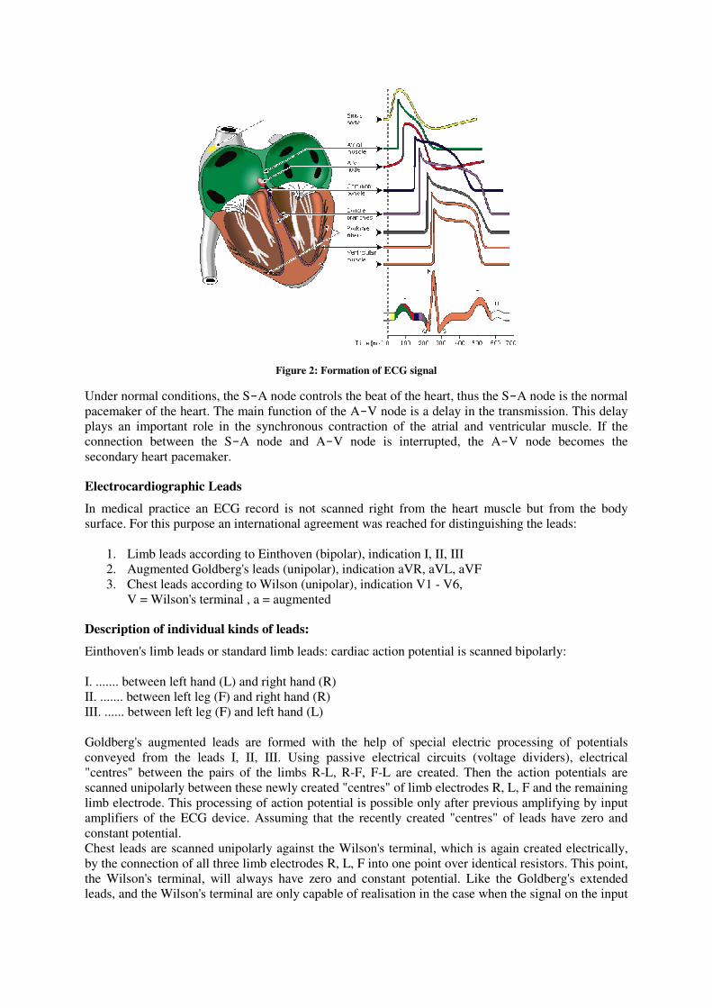
Figure 2: Formation of ECG signal
Under normal conditions, the S-A node controls the beat of the heart, thus the S-A node is the normal
pacemaker of the heart. The main function of the A-V node is a delay in the transmission. This delay
plays an important role in the synchronous contraction of the atrial and ventricular muscle. If the
connection between the S-A node and A-V node is interrupted, the A-V node becomes the
secondary heart pacemaker.
Electrocardiographic Leads
In medical practice an ECG record is not scanned right from the heart muscle but from the body
surface. For this purpose an international agreement was reached for distinguishing the leads:
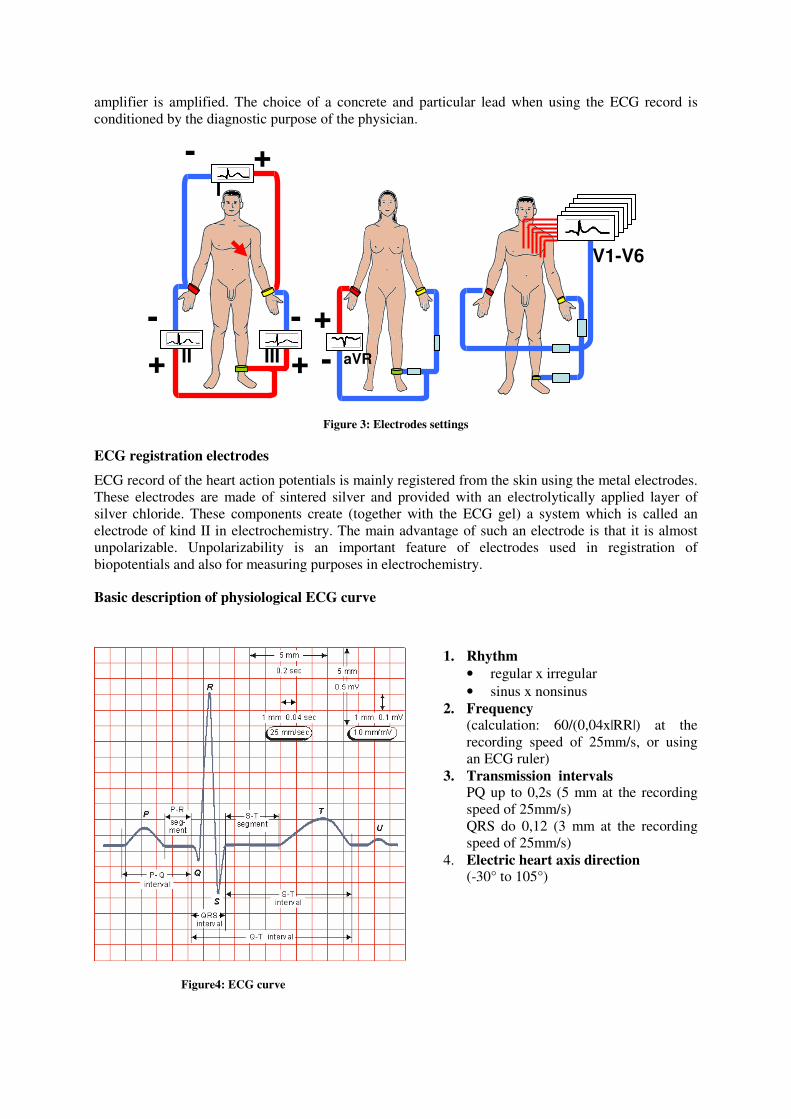
1. Limb leads according to Einthoven (bipolar), indication I, II, III
2. Augmented Goldberg's leads (unipolar), indication aVR, aVL, aVF
3. Chest leads according to Wilson (unipolar), indication V1 - V6,
V = Wilson's terminal , a = augmented
Description of individual kinds of leads:
Einthoven's limb leads or standard limb leads: cardiac action potential is scanned bipolarly:
I. ....... between left hand (L) and right hand (R)
II. ....... between left leg (F) and right hand (R)
III. ...... between left leg (F) and left hand (L)
Goldberg's augmented leads are formed with the help of special electric processing of potentials
conveyed from the leads I, II, III. Using passive electrical circuits (voltage dividers), electrical
"centres" between the pairs of the limbs R-L, R-F, F-L are created. Then the action potentials are
scanned unipolarly between these newly created "centres" of limb electrodes R, L, F and the remaining
limb electrode. This processing of action potential is possible only after previous amplifying by input
amplifiers of the ECG device. Assuming that the recently created "centres" of leads have zero and
constant potential.
Chest leads are scanned unipolarly against the Wilson's terminal, which is again created electrically,
by the connection of all three limb electrodes R, L, F into one point over identical resistors. This point,
the Wilson's terminal, will always have zero and constant potential. Like the Goldberg's extended
leads, and the Wilson's terminal are only capable of realisation in the case when the signal on the input
amplifier is amplified. The choice of a concrete and particular lead when using the ECG record is
conditioned by the diagnostic purpose of the physician.
Figure 3: Electrodes settings
ECG registration electrodes
ECG record of the heart action potentials is mainly registered from the skin using the metal electrodes.
These electrodes are made of sintered silver and provided with an electrolytically applied layer of
silver chloride. These components create (together with the ECG gel) a system which is called an
electrode of kind II in electrochemistry. The main advantage of such an electrode is that it is almost
unpolarizable. Unpolarizability is an important feature of electrodes used in registration of
biopotentials and also for measuring purposes in electrochemistry.
Basic description of physiological ECG curve
Figure4: ECG curve
1. Rhythm
• regular x irregular
• sinus x nonsinus
2. Frequency (calculation: 60/(0,04x|RR|) at the
recording speed of 25mm/s, or using
an ECG ruler)
3. Transmission intervals PQ up to 0,2s (5 mm at the recording
speed of 25mm/s)
QRS do 0,12 (3 mm at the recording
speed of 25mm/s)
4. Electric heart axis direction (-30° to 105°)
V1-V6
I
II III aVR + +
+ -
- - +
-
Evaluation of ECG record
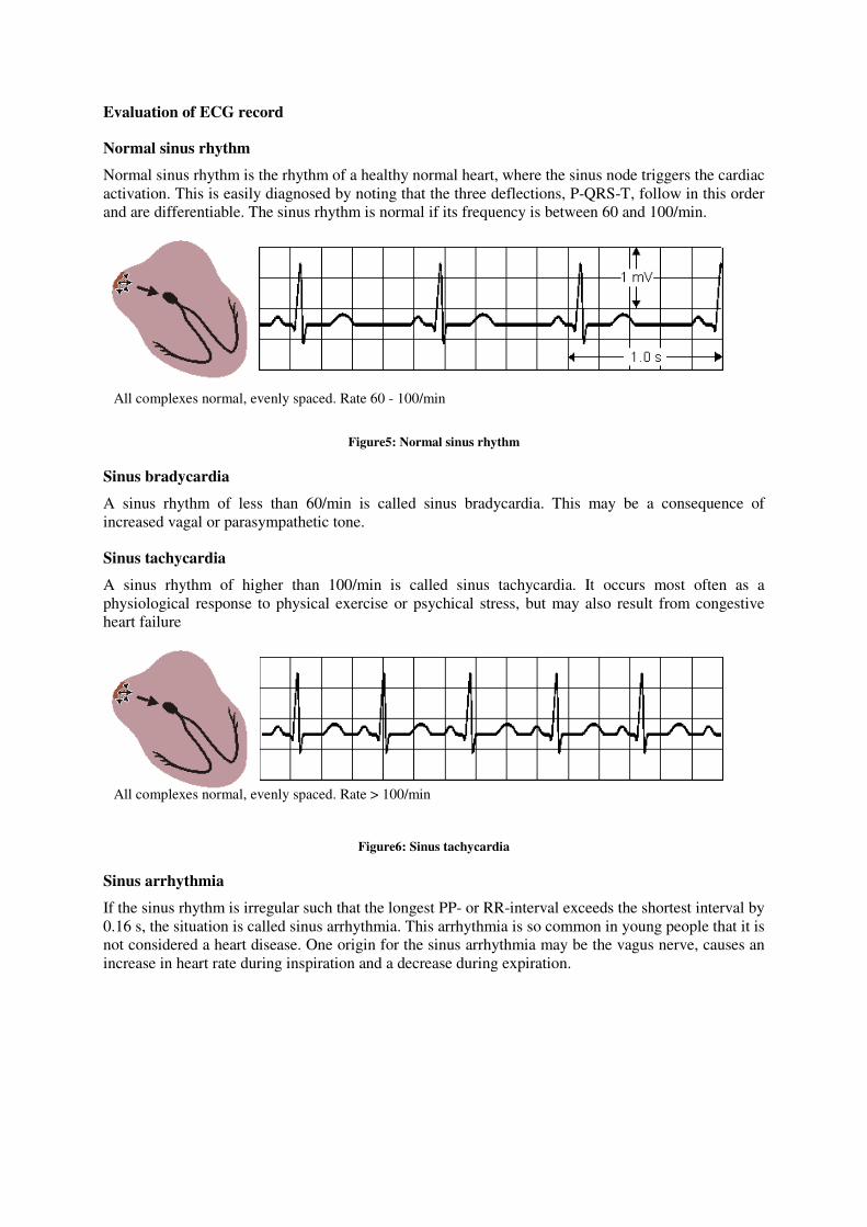
Normal sinus rhythm
Normal sinus rhythm is the rhythm of a healthy normal heart, where the sinus node triggers the cardiac
activation. This is easily diagnosed by noting that the three deflections, P-QRS-T, follow in this order
and are differentiable. The sinus rhythm is normal if its frequency is between 60 and 100/min.
Figure5: Normal sinus rhythm
Sinus bradycardia
A sinus rhythm of less than 60/min is called sinus bradycardia. This may be a consequence of
increased vagal or parasympathetic tone.
Sinus tachycardia
A sinus rhythm of higher than 100/min is called sinus tachycardia. It occurs most often as a
physiological response to physical exercise or psychical stress, but may also result from congestive
heart failure
Figure6: Sinus tachycardia
Sinus arrhythmia
If the sinus rhythm is irregular such that the longest PP- or RR-interval exceeds the shortest interval by
0.16 s, the situation is called sinus arrhythmia. This arrhythmia is so common in young people that it is
not considered a heart disease. One origin for the sinus arrhythmia may be the vagus nerve, causes an
increase in heart rate during inspiration and a decrease during expiration.
All complexes normal, evenly spaced. Rate > 100/min
All complexes normal, evenly spaced. Rate 60 - 100/min
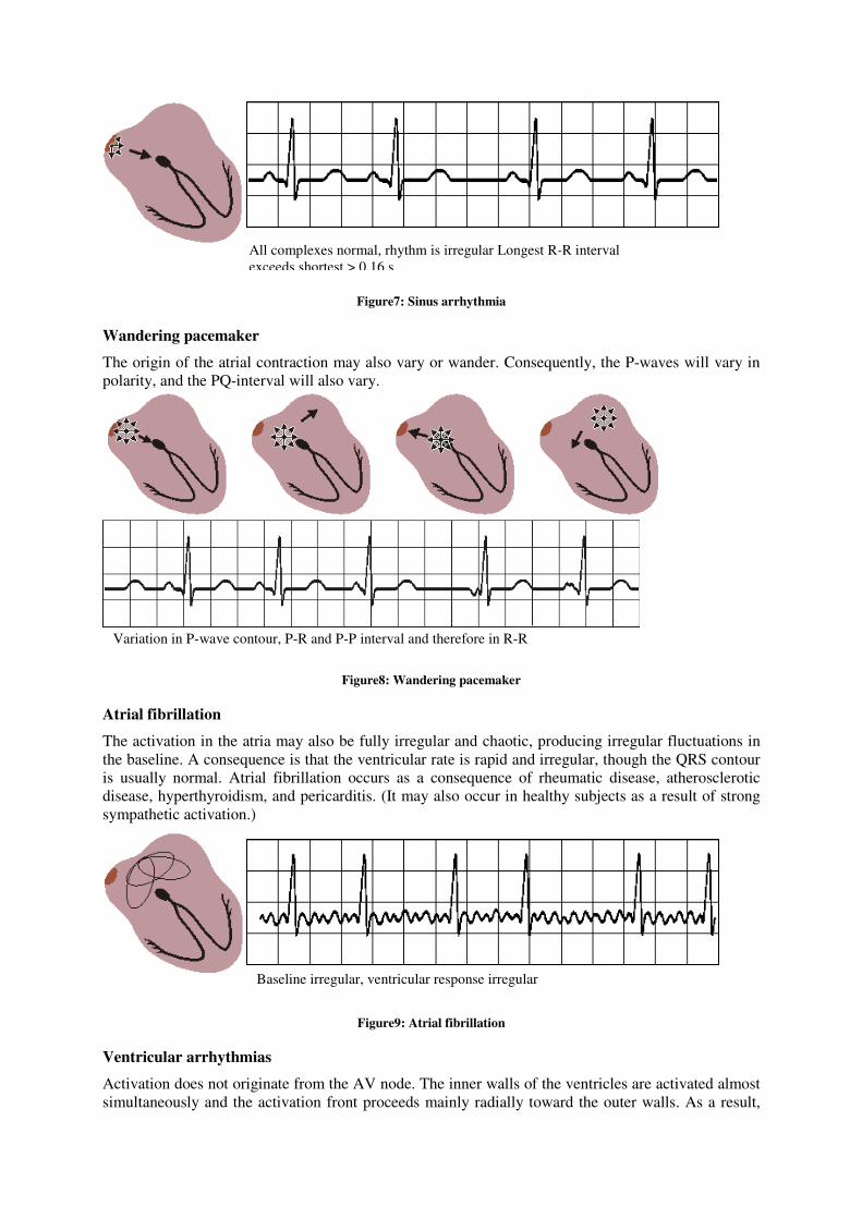
Figure7: Sinus arrhythmia
Wandering pacemaker
The origin of the atrial contraction may also vary or wander. Consequently, the P-waves will vary in
polarity, and the PQ-interval will also vary.
Figure8: Wandering pacemaker
Atrial fibrillation
The activation in the atria may also be fully irregular and chaotic, producing irregular fluctuations in
the baseline. A consequence is that the ventricular rate is rapid and irregular, though the QRS contour
is usually normal. Atrial fibrillation occurs as a consequence of rheumatic disease, atherosclerotic
disease, hyperthyroidism, and pericarditis. (It may also occur in healthy subjects as a result of strong
sympathetic activation.)
Figure9: Atrial fibrillation
Ventricular arrhythmias
Activation does not originate from the AV node. The inner walls of the ventricles are activated almost
simultaneously and the activation front proceeds mainly radially toward the outer walls. As a result,
Baseline irregular, ventricular response irregular
Variation in P-wave contour, P-R and P-P interval and therefore in R-R
intervals
All complexes normal, rhythm is irregular Longest R-R interval
exceeds shortest > 0.16 s
the QRS-complex is of relatively short duration. (The criterion for normal ventricular activation is a
QRS-interval shorter than 0.1 s. ).
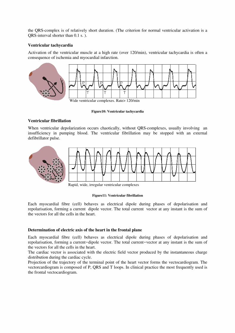
Ventricular tachycardia
Activation of the ventricular muscle at a high rate (over 120/min), ventricular tachycardia is often a
consequence of ischemia and myocardial infarction.
Figure10: Ventricular tachycardia
Ventricular fibrillation
When ventricular depolarization occurs chaotically, without QRS-complexes, usually involving an
insufficiency in pumping blood. The ventricular fibrillation may be stopped with an external
defibrillator pulse.
Figure11: Ventricular fibrillation
Each myocardial fibre (cell) behaves as electrical dipole during phases of depolarisation and
repolarisation, forming a current�dipole vector. The total current�vector at any instant is the sum of
the vectors for all the cells in the heart.
Determination of electric axis of the heart in the frontal plane
Each myocardial fibre (cell) behaves as electrical dipole during phases of depolarisation and
repolarisation, forming a current-dipole vector. The total current-vector at any instant is the sum of
the vectors for all the cells in the heart.
The cardiac vector is associated with the electric field vector produced by the instantaneous charge
distribution during the cardiac cycle.
Projection of the trajectory of the terminal point of the heart vector forms the vectocardiogram. The
vectorcardiogram is composed of P, QRS and T loops. In clinical practice the most frequently used is
the frontal vectocardiogram.
Rapid, wide, irregular ventricular complexes
Wide ventricular complexes. Rate> 120/min
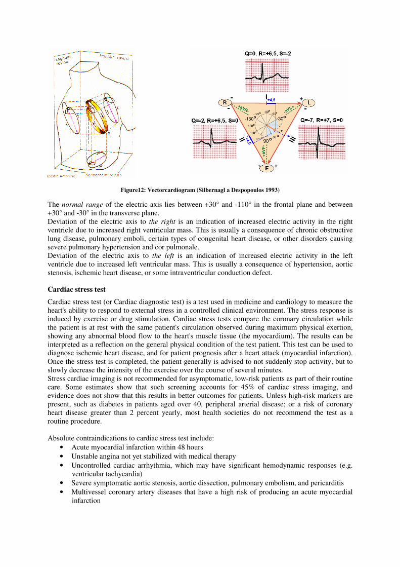
Figure12: Vectorcardiogram (Silbernagl a Despopoulos 1993)
The normal range of the electric axis lies between +30° and -110° in the frontal plane and between
+30° and -30° in the transverse plane.
Deviation of the electric axis to the right is an indication of increased electric activity in the right
ventricle due to increased right ventricular mass. This is usually a consequence of chronic obstructive
lung disease, pulmonary emboli, certain types of congenital heart disease, or other disorders causing
severe pulmonary hypertension and cor pulmonale.
Deviation of the electric axis to the left is an indication of increased electric activity in the left
ventricle due to increased left ventricular mass. This is usually a consequence of hypertension, aortic
stenosis, ischemic heart disease, or some intraventricular conduction defect.
Cardiac stress test
Cardiac stress test (or Cardiac diagnostic test) is a test used in medicine and cardiology to measure the
heart's ability to respond to external stress in a controlled clinical environment. The stress response is
induced by exercise or drug stimulation. Cardiac stress tests compare the coronary circulation while
the patient is at rest with the same patient's circulation observed during maximum physical exertion,
showing any abnormal blood flow to the heart's muscle tissue (the myocardium). The results can be
interpreted as a reflection on the general physical condition of the test patient. This test can be used to
diagnose ischemic heart disease, and for patient prognosis after a heart attack (myocardial infarction).
Once the stress test is completed, the patient generally is advised to not suddenly stop activity, but to
slowly decrease the intensity of the exercise over the course of several minutes.
Stress cardiac imaging is not recommended for asymptomatic, low-risk patients as part of their routine
care. Some estimates show that such screening accounts for 45% of cardiac stress imaging, and
evidence does not show that this results in better outcomes for patients. Unless high-risk markers are
present, such as diabetes in patients aged over 40, peripheral arterial disease; or a risk of coronary
heart disease greater than 2 percent yearly, most health societies do not recommend the test as a
routine procedure.
Absolute contraindications to cardiac stress test include:
• Acute myocardial infarction within 48 hours
• Unstable angina not yet stabilized with medical therapy
• Uncontrolled cardiac arrhythmia, which may have significant hemodynamic responses (e.g.
ventricular tachycardia)
• Severe symptomatic aortic stenosis, aortic dissection, pulmonary embolism, and pericarditis
• Multivessel coronary artery diseases that have a high risk of producing an acute myocardial
infarction
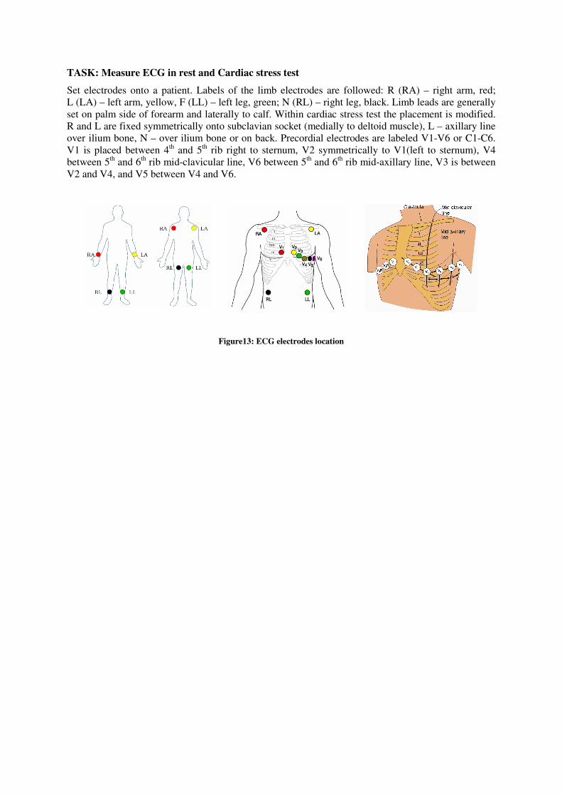
TASK: Measure ECG in rest and Cardiac stress test
Set electrodes onto a patient. Labels of the limb electrodes are followed: R (RA) – right arm, red;
L (LA) – left arm, yellow, F (LL) – left leg, green; N (RL) – right leg, black. Limb leads are generally
set on palm side of forearm and laterally to calf. Within cardiac stress test the placement is modified.
R and L are fixed symmetrically onto subclavian socket (medially to deltoid muscle), L – axillary line
over ilium bone, N – over ilium bone or on back. Precordial electrodes are labeled V1-V6 or C1-C6.
V1 is placed between 4th and 5
th rib right to sternum, V2 symmetrically to V1(left to sternum), V4
between 5th and 6
th rib mid-clavicular line, V6 between 5
th and 6
th rib mid-axillary line, V3 is between
V2 and V4, and V5 between V4 and V6.
Figure13: ECG electrodes location
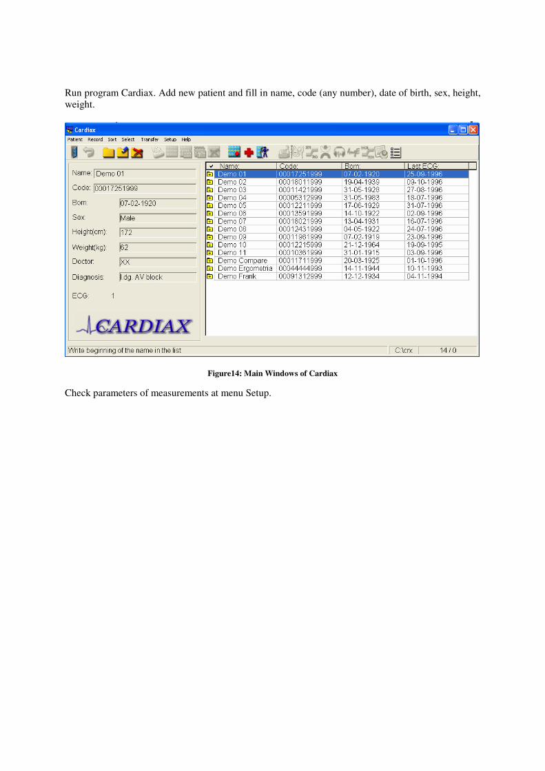
Run program Cardiax. Add new patient and fill in name, code (any number), date of birth, sex, height,
weight.
Figure14: Main Windows of Cardiax
Check parameters of measurements at menu Setup.
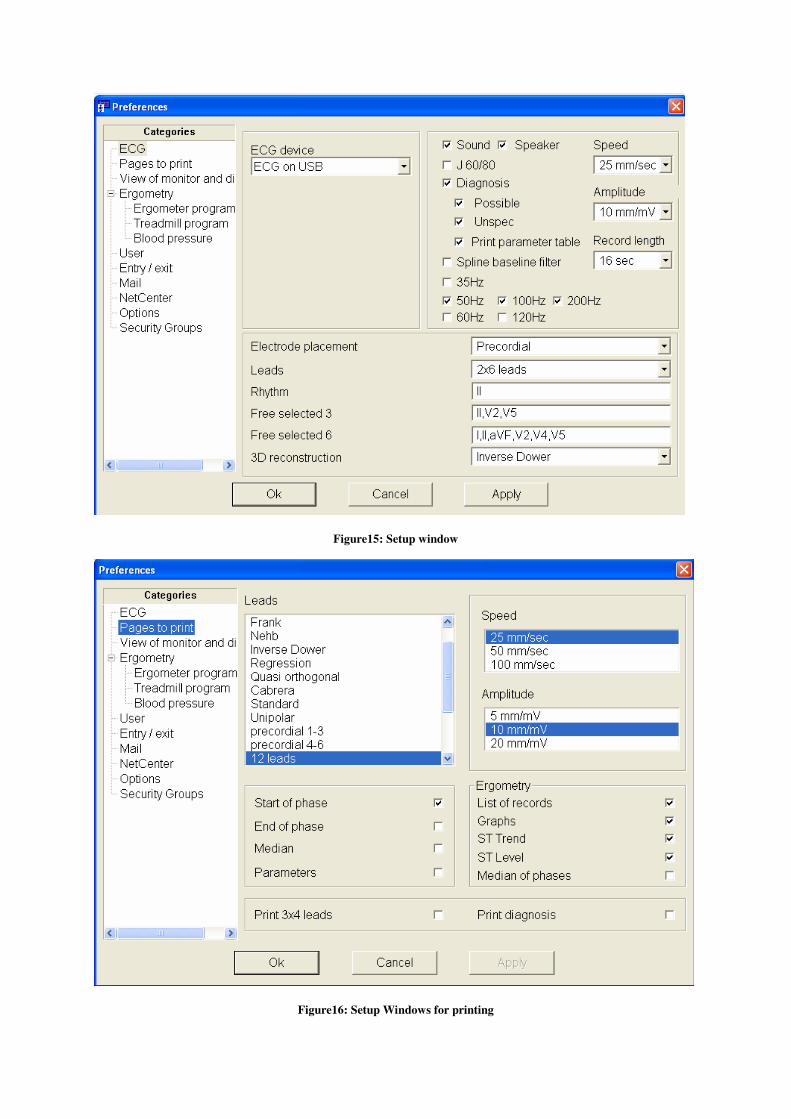
Figure15: Setup window
Figure16: Setup Windows for printing
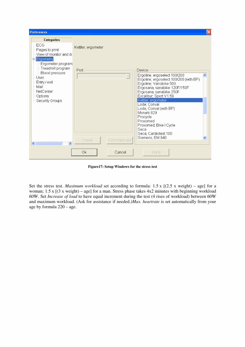
Figure17: Setup Windows for the stress test
Set the stress test. Maximum workload set according to formula: 1.5 x [(2.5 x weight) – age] for a
woman; 1.5 x [(3 x weight) – age] for a man. Stress phase takes 4x2 minutes with beginning workload
60W. Set Increase of load to have equal increment during the test (4 rises of workload) between 60W
and maximum workload. (Ask for assistance if needed.)Max. heartrate is set automatically from your
age by formula 220 – age.
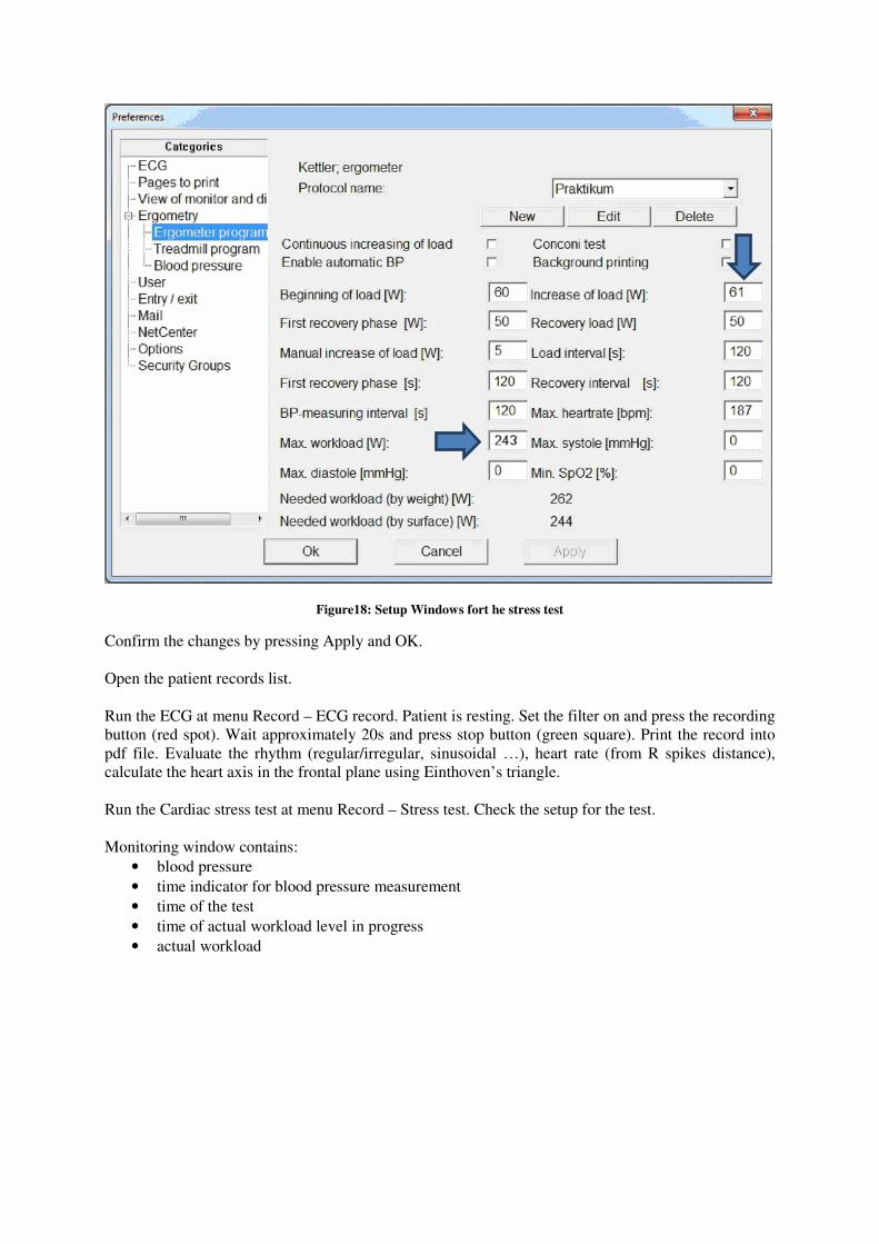
Figure18: Setup Windows fort he stress test
Confirm the changes by pressing Apply and OK.
Open the patient records list.
Run the ECG at menu Record – ECG record. Patient is resting. Set the filter on and press the recording
button (red spot). Wait approximately 20s and press stop button (green square). Print the record into
pdf file. Evaluate the rhythm (regular/irregular, sinusoidal …), heart rate (from R spikes distance),
calculate the heart axis in the frontal plane using Einthoven’s triangle.
Run the Cardiac stress test at menu Record – Stress test. Check the setup for the test.
Monitoring window contains:
• blood pressure
• time indicator for blood pressure measurement
• time of the test
• time of actual workload level in progress
• actual workload
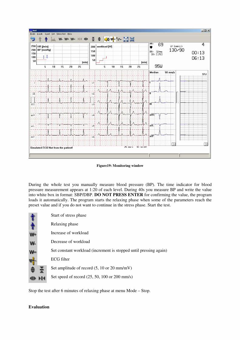
Figure19: Monitoring window
During the whole test you manually measure blood pressure (BP). The time indicator for blood
pressure measurement appears at 1:20 of each level. During 40s you measure BP and write the value
into white box in format: SBP/DBP. DO NOT PRESS ENTER for confirming the value, the program
loads it automatically. The program starts the relaxing phase when some of the parameters reach the
preset value and if you do not want to continue in the stress phase. Start the test.
Start of stress phase
Relaxing phase
Increase of workload
Decrease of workload
Set constant workload (increment is stopped until pressing again)
ECG filter
Set amplitude of record (5, 10 or 20 mm/mV)
Set speed of record (25, 50, 100 or 200 mm/s)
Stop the test after 6 minutes of relaxing phase at menu Mode – Stop.
Evaluation
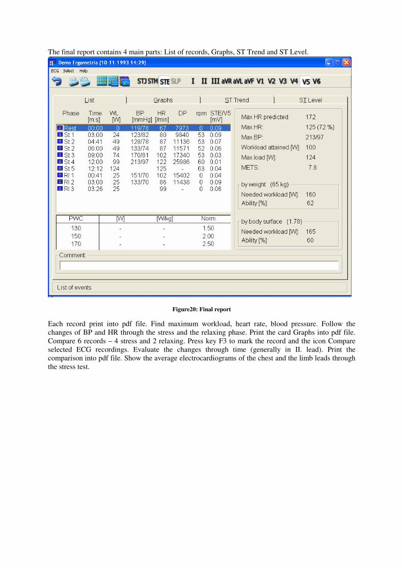
The final report contains 4 main parts: List of records, Graphs, ST Trend and ST Level.
Figure20: Final report
Each record print into pdf file. Find maximum workload, heart rate, blood pressure. Follow the
changes of BP and HR through the stress and the relaxing phase. Print the card Graphs into pdf file.
Compare 6 records – 4 stress and 2 relaxing. Press key F3 to mark the record and the icon Compare
selected ECG recordings. Evaluate the changes through time (generally in II. lead). Print the
comparison into pdf file. Show the average electrocardiograms of the chest and the limb leads through
the stress test.
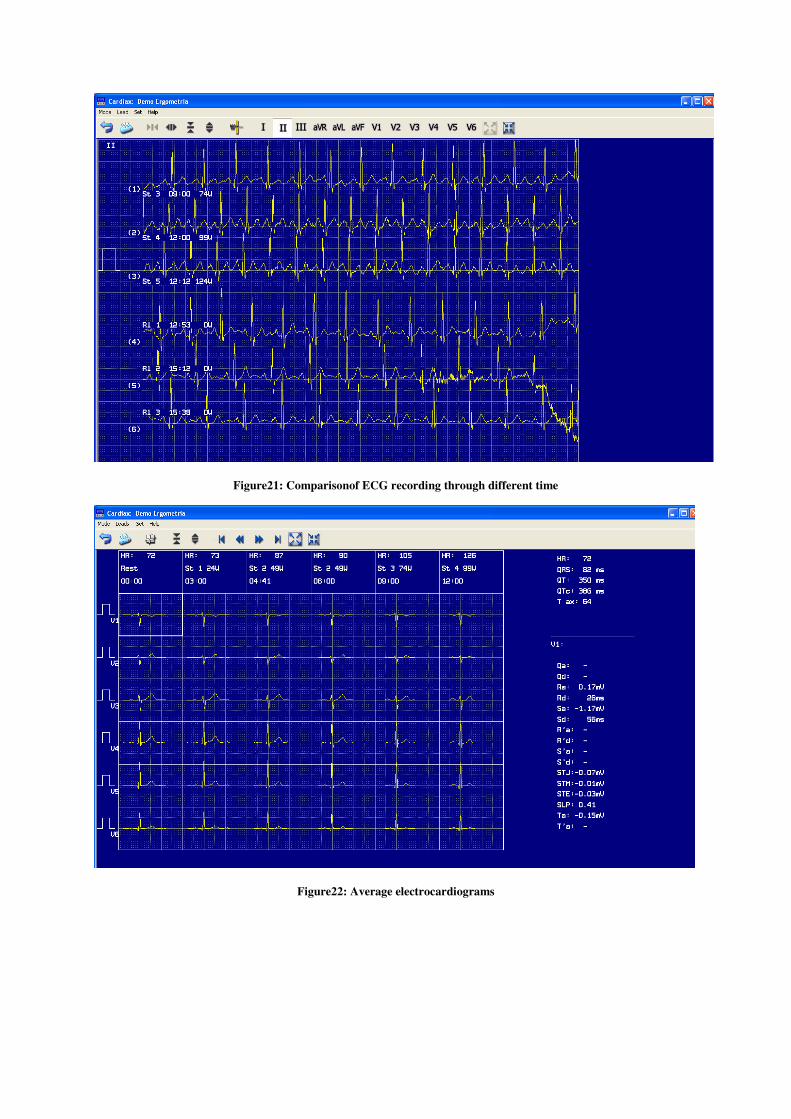
Figure21: Comparisonof ECG recording through different time
Figure22: Average electrocardiograms

Resources:
Malmivuo J, Plonsey R. Bioelectromagnetism. http://www.bem.fi/
Silbernagl S a Despopoulos A. Atlas fyziologie člověka. Grada 1993.
Widimský J a Lefflerová K. Zátěžové EKG testy v kardiologii. Triton 2003.
Chaloupka V, Elbl L a kolektiv. Zátěžové metody v kardiologii. Grada 2003.
Hampton JR. EKG stručně, jasně, přehledně. Grada 1996.