Embed Size (px)
Citation preview
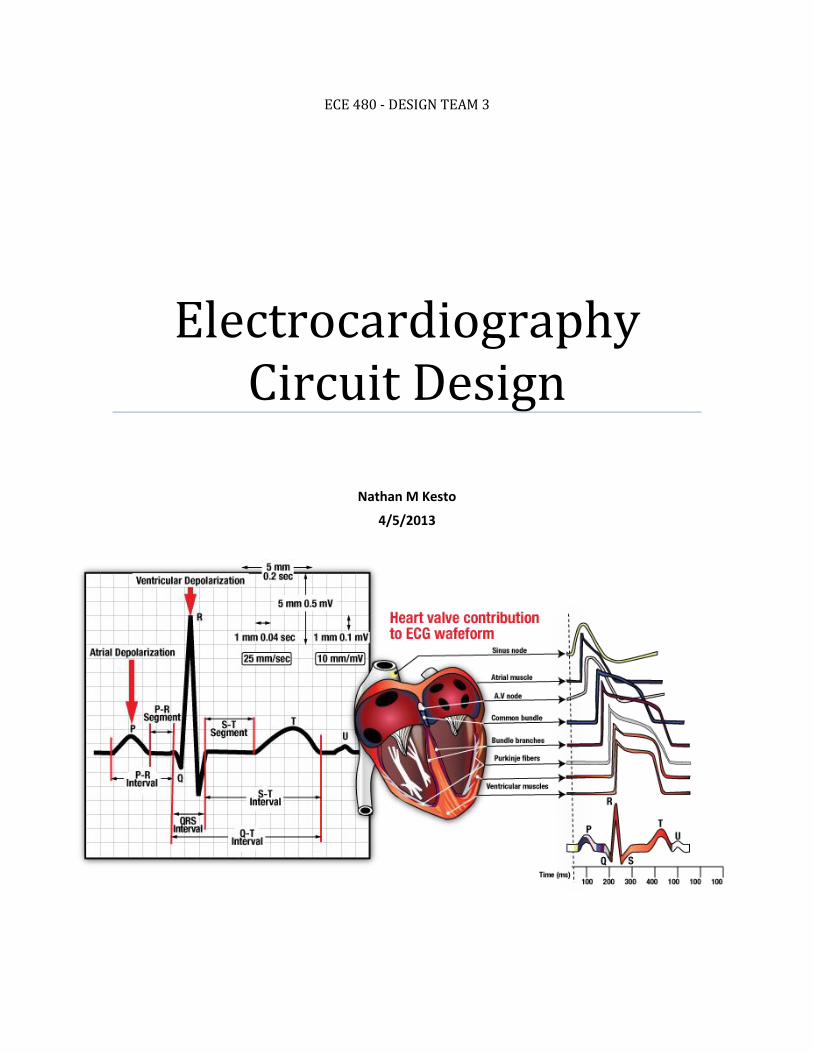
ECE 480 - DESIGN TEAM 3
Electrocardiography Circuit Design
Nathan M Kesto
4/5/2013
1
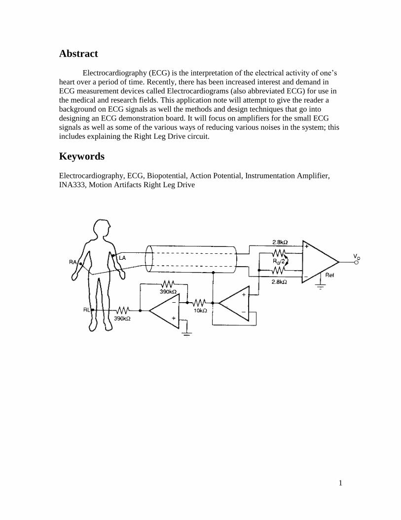
Abstract
Electrocardiography (ECG) is the interpretation of the electrical activity of one’s
heart over a period of time. Recently, there has been increased interest and demand in
ECG measurement devices called Electrocardiograms (also abbreviated ECG) for use in
the medical and research fields. This application note will attempt to give the reader a
background on ECG signals as well the methods and design techniques that go into
designing an ECG demonstration board. It will focus on amplifiers for the small ECG
signals as well as some of the various ways of reducing various noises in the system; this
includes explaining the Right Leg Drive circuit.
Keywords
Electrocardiography, ECG, Biopotential, Action Potential, Instrumentation Amplifier,
INA333, Motion Artifacts Right Leg Drive

2
Table of Contents Executive Summary .......................................................................................................................... 1
Keywords .......................................................................................................................................... 1
Electrocardiography ......................................................................................................................... 3
Circuit Design .................................................................................................................................... 4
Amplifier ............................................................................................................................... 4-5
Filtering ................................................................................................................................. 6-7
Right Leg Drive.......................................................................................................................... 7
ECG Circuit ................................................................................................................................ 8
References ........................................................................................................................................ 9
3
Electrocardiography
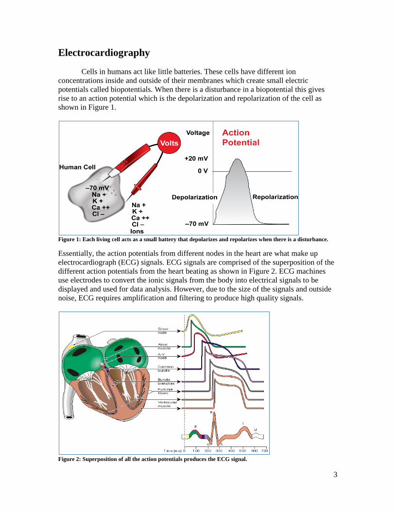
Cells in humans act like little batteries. These cells have different ion
concentrations inside and outside of their membranes which create small electric
potentials called biopotentials. When there is a disturbance in a biopotential this gives
rise to an action potential which is the depolarization and repolarization of the cell as
shown in Figure 1.
Figure 1: Each living cell acts as a small battery that depolarizes and repolarizes when there is a disturbance.
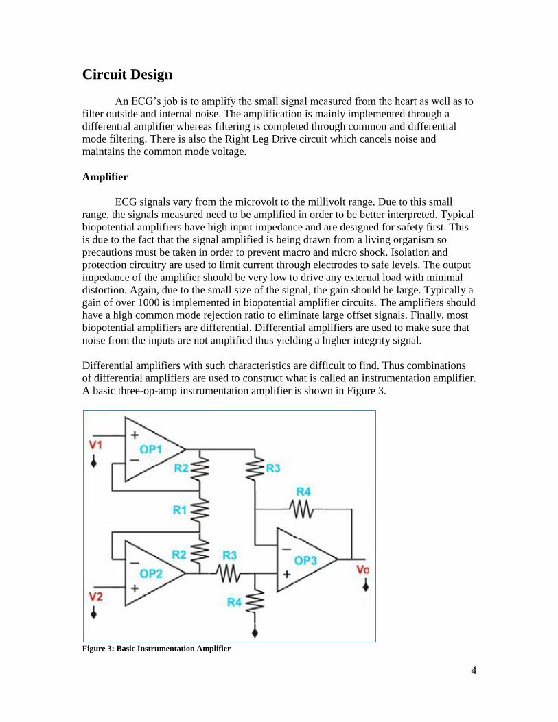
Essentially, the action potentials from different nodes in the heart are what make up
electrocardiograph (ECG) signals. ECG signals are comprised of the superposition of the
different action potentials from the heart beating as shown in Figure 2. ECG machines
use electrodes to convert the ionic signals from the body into electrical signals to be
displayed and used for data analysis. However, due to the size of the signals and outside
noise, ECG requires amplification and filtering to produce high quality signals.
Figure 2: Superposition of all the action potentials produces the ECG signal.
4
Circuit Design
An ECG’s job is to amplify the small signal measured from the heart as well as to
filter outside and internal noise. The amplification is mainly implemented through a
differential amplifier whereas filtering is completed through common and differential
mode filtering. There is also the Right Leg Drive circuit which cancels noise and
maintains the common mode voltage.
Amplifier
ECG signals vary from the microvolt to the millivolt range. Due to this small
range, the signals measured need to be amplified in order to be better interpreted. Typical
biopotential amplifiers have high input impedance and are designed for safety first. This
is due to the fact that the signal amplified is being drawn from a living organism so
precautions must be taken in order to prevent macro and micro shock. Isolation and
protection circuitry are used to limit current through electrodes to safe levels. The output
impedance of the amplifier should be very low to drive any external load with minimal
distortion. Again, due to the small size of the signal, the gain should be large. Typically a
gain of over 1000 is implemented in biopotential amplifier circuits. The amplifiers should
have a high common mode rejection ratio to eliminate large offset signals. Finally, most
biopotential amplifiers are differential. Differential amplifiers are used to make sure that
noise from the inputs are not amplified thus yielding a higher integrity signal.
Differential amplifiers with such characteristics are difficult to find. Thus combinations
of differential amplifiers are used to construct what is called an instrumentation amplifier.
A basic three-op-amp instrumentation amplifier is shown in Figure 3.
Figure 3: Basic Instrumentation Amplifier
5
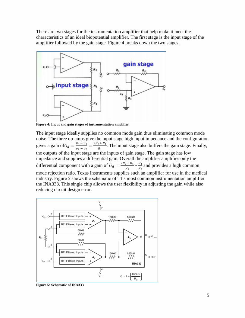
There are two stages for the instrumentation amplifier that help make it meet the
characteristics of an ideal biopotential amplifier. The first stage is the input stage of the
amplifier followed by the gain stage. Figure 4 breaks down the two stages.
Figure 4: Input and gain stages of instrumentation amplifier
The input stage ideally supplies no common mode gain thus eliminating common mode
noise. The three op-amps give the input stage high input impedance and the configuration
gives a gain of
. The input stage also buffers the gain stage. Finally,
the outputs of the input stage are the inputs of gain stage. The gain stage has low
impedance and supplies a differential gain. Overall the amplifier amplifies only the
differential component with a gain of
and provides a high common
mode rejection ratio. Texas Instruments supplies such an amplifier for use in the medical
industry. Figure 5 shows the schematic of TI’s most common instrumentation amplifier
the INA333. This single chip allows the user flexibility in adjusting the gain while also
reducing circuit design error.
Figure 5: Schematic of INA333
6
Filtering
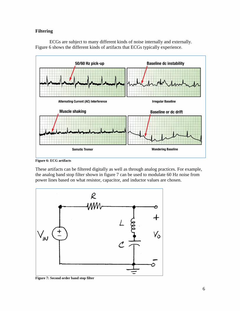
ECGs are subject to many different kinds of noise internally and externally.
Figure 6 shows the different kinds of artifacts that ECGs typically experience.
Figure 6: ECG artifacts
These artifacts can be filtered digitally as well as through analog practices. For example,
the analog band stop filter shown in figure 7 can be used to modulate 60 Hz noise from
power lines based on what resistor, capacitor, and inductor values are chosen.
Figure 7: Second order band stop filter
7
Digitally, Matlab allows one to implement filters with the help of FFTs. For example, an
FFT can extract the ECG and muscle shaking frequency components. From there, one
can design a filter to obtain only the ECG components of the signal. For ECG circuits
however, typically low pass filters will suffice to eliminate outside noise due to the
frequency of a heartbeat.
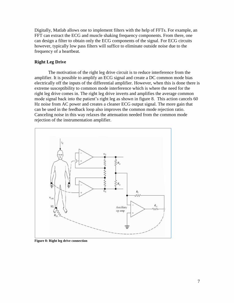
Right Leg Drive
The motivation of the right leg drive circuit is to reduce interference from the
amplifier. It is possible to amplify an ECG signal and create a DC common mode bias
electrically off the inputs of the differential amplifier. However, when this is done there is
extreme susceptibility to common mode interference which is where the need for the
right leg drive comes in. The right leg drive inverts and amplifies the average common
mode signal back into the patient’s right leg as shown in figure 8. This action cancels 60
Hz noise from AC power and creates a cleaner ECG output signal. The more gain that
can be used in the feedback loop also improves the common mode rejection ratio.
Canceling noise in this way relaxes the attenuation needed from the common mode
rejection of the instrumentation amplifier.
Figure 8: Right leg drive connection
8
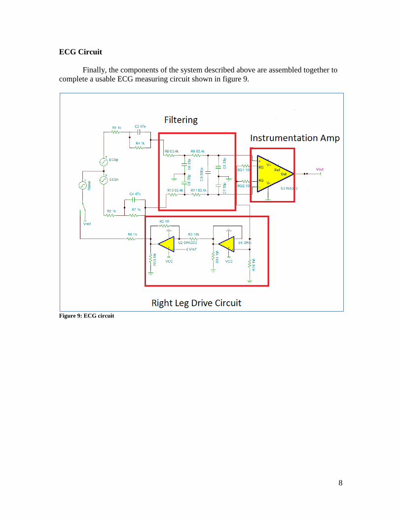
ECG Circuit
Finally, the components of the system described above are assembled together to
complete a usable ECG measuring circuit shown in figure 9.
Figure 9: ECG circuit

9
References
A precision low-level DAS/ECG Cardiotachometer Demo Board, a
Texas Instruments technical presentation created by John Brown.
Analog Fundamentals of the ECG Signal Chain, a Texas
Instruments technical presentation prepared by Matthew Hann.
ECE 445 Biopotential amplifiers prepared by Professor Andrew Mason
INA333 data sheet
http://www.ti.com/product/ina333?DCMP=A_Signal%252520Chai
n_Precision_Amps%252520&%252520Linear&247SEM