Embed Size (px)
Citation preview

ELECTRICITY & MAGNETISM
LECTURE # 15
BY
MOEEN GHIYAS

TODAY’S LESSON
(Capacitors– Chapter 10)
Introductory Circuit Analysis by Boylested (10th Edition)

Today’s Lesson Contents
• Introduction
• Electric Field
• Capacitance
• Dielectric Strength
• Leakage Current
Introduction
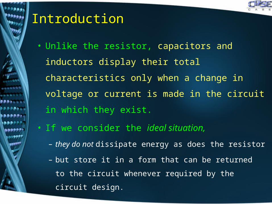
• Unlike the resistor, capacitors and inductors
display their total characteristics only when a
change in voltage or current is made in the
circuit in which they exist.
• If we consider the ideal situation,
– they do not dissipate energy as does the resistor
– but store it in a form that can be returned to the
circuit whenever required by the circuit design.
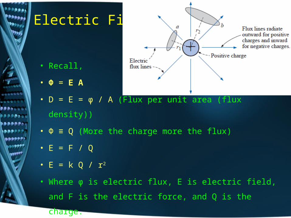
Electric Field
• Recall,
• Φ = E A
• D = E = φ / A (Flux per unit area (flux density))
• Φ ≡ Q (More the charge more the flux)
• E = F / Q
• E = k Q / r2
• Where φ is electric flux, E is electric field, and F is the
electric force, and Q is the charge.
Capacitance
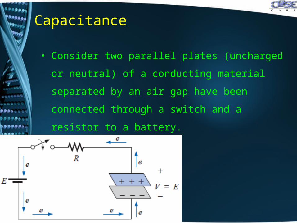
• Consider two parallel plates (uncharged or neutral) of
a conducting material separated by an air gap have
been connected through a switch and a resistor to a
battery.
Capacitance
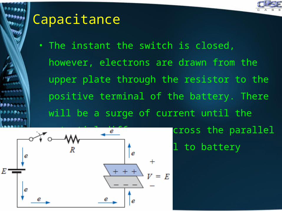
• The instant the switch is closed, however, electrons
are drawn from the upper plate through the resistor to
the positive terminal of the battery. There will be a
surge of current until the potential difference across
the parallel plates is exactly equal to battery voltage.
Capacitance
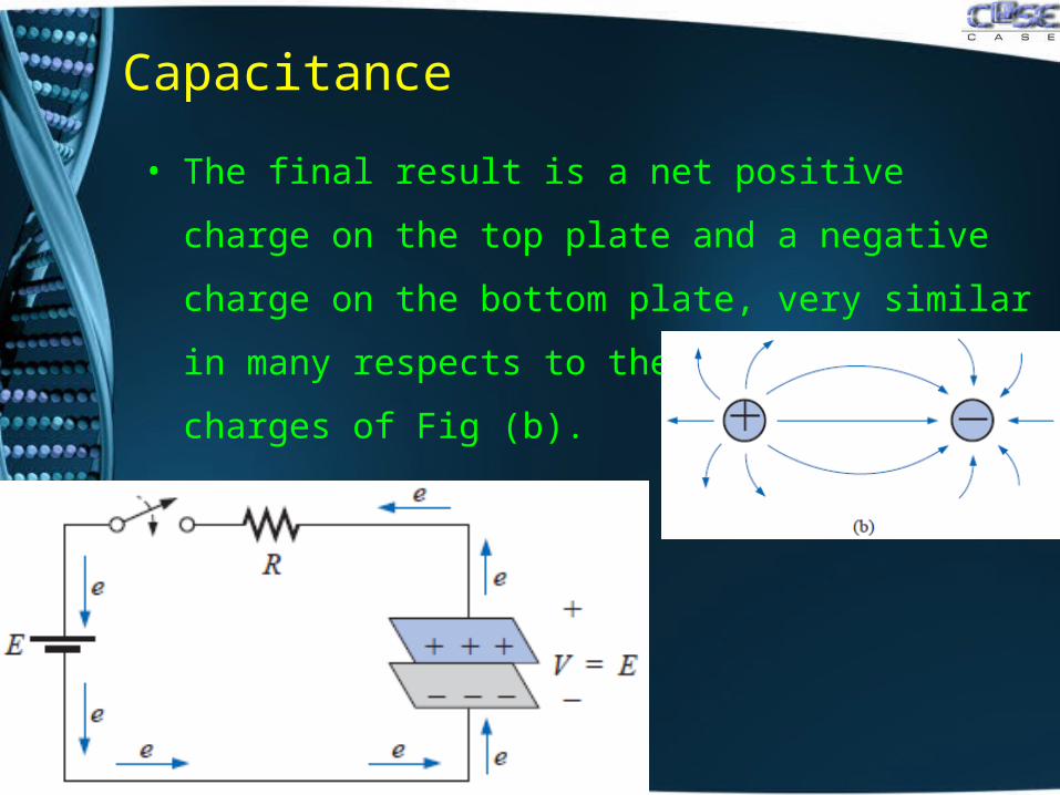
• The final result is a net positive charge on the top
plate and a negative charge on the bottom plate, very
similar in many respects to the two isolated charges of
Fig (b).
Capacitance
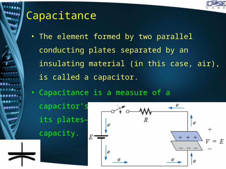
• The element formed by two parallel conducting plates
separated by an insulating material (in this case, air),
is called a capacitor.
• Capacitance is a measure of a capacitor’s ability to
store charge on its plates—in other words, its storage
capacity.
Capacitance
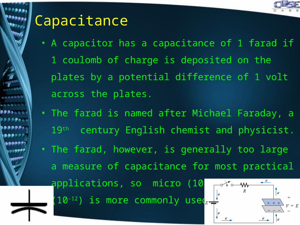
• A capacitor has a capacitance of 1 farad if 1 coulomb
of charge is deposited on the plates by a potential
difference of 1 volt across the plates.
• The farad is named after Michael Faraday, a 19th
century English chemist and physicist.
• The farad, however, is generally too large a measure of
capacitance for most practical applications, so micro
(10-6) or picofarad (10-12) is more commonly used.
Capacitance
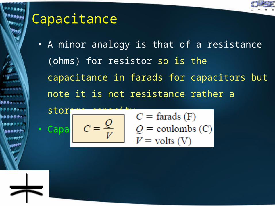
• A minor analogy is that of a resistance (ohms) for
resistor so is the capacitance in farads for capacitors
but note it is not resistance rather a storage capacity.
• Capacitance is determined by
Capacitance
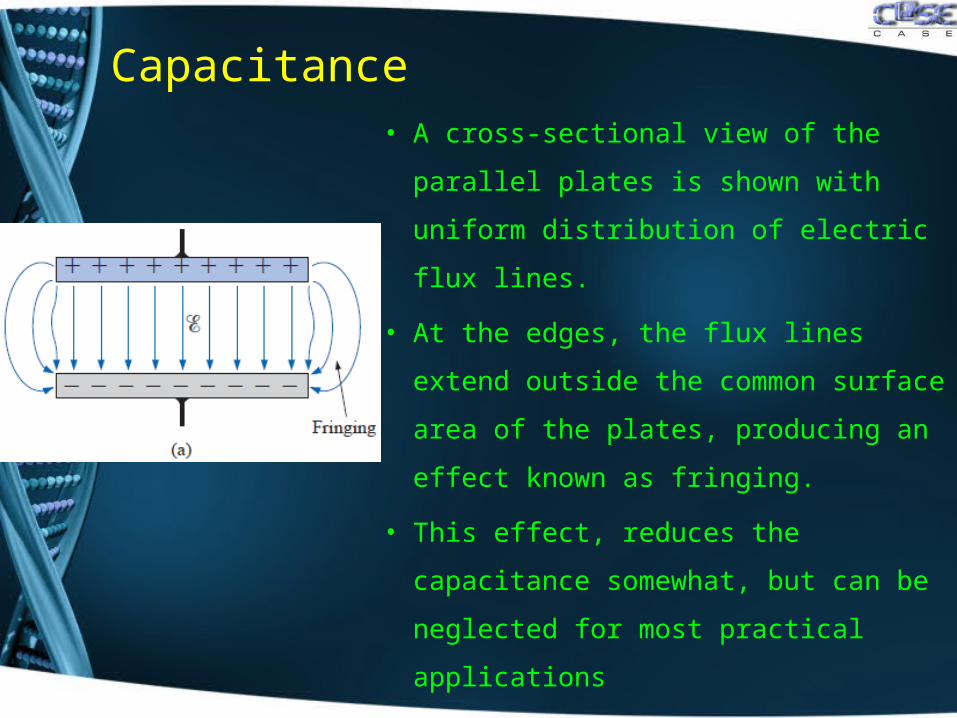
• A cross-sectional view of the parallel
plates is shown with uniform
distribution of electric flux lines.
• At the edges, the flux lines extend
outside the common surface area of
the plates, producing an effect known
as fringing.
• This effect, reduces the capacitance
somewhat, but can be neglected for
most practical applications
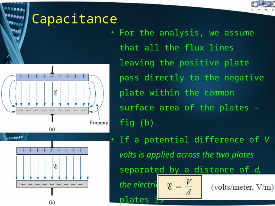
Capacitance• For the analysis, we assume that all
the flux lines leaving the positive
plate pass directly to the negative
plate within the common surface
area of the plates – fig (b)
• If a potential difference of V volts is
applied across the two plates
separated by a distance of d, the
electric field strength between the
plates is
Capacitance
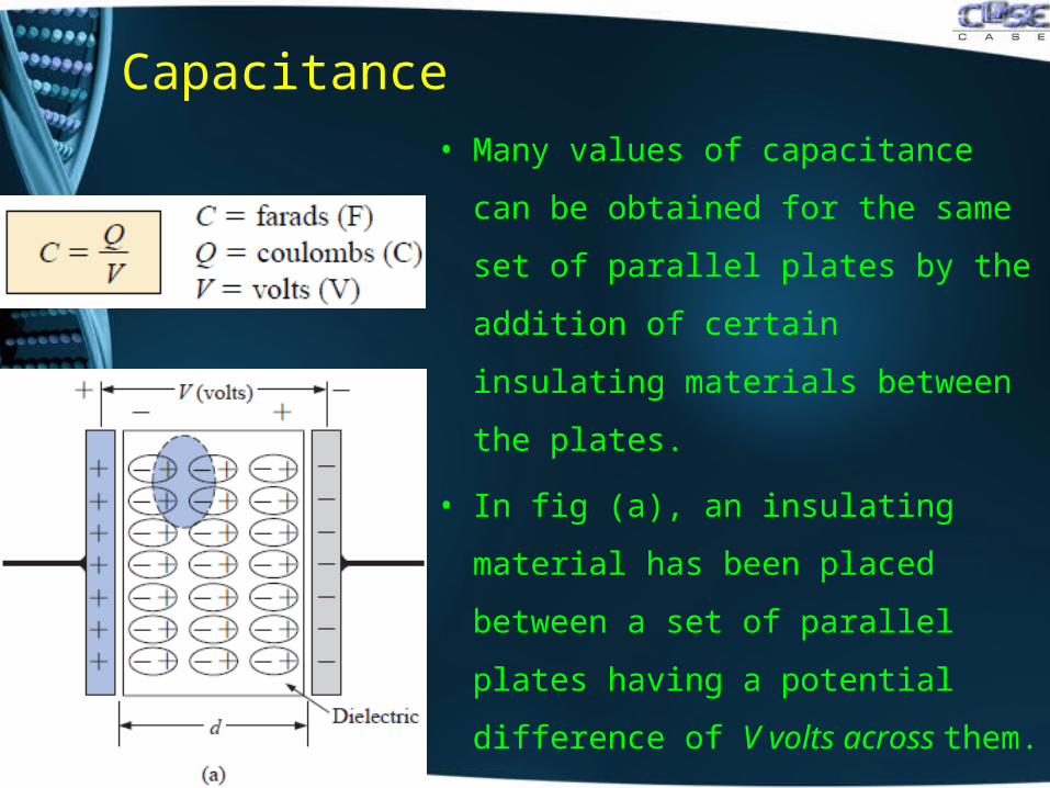
• Many values of capacitance can be
obtained for the same set of parallel
plates by the addition of certain
insulating materials between the
plates.
• In fig (a), an insulating material has
been placed between a set of
parallel plates having a potential
difference of V volts across them.
Capacitance
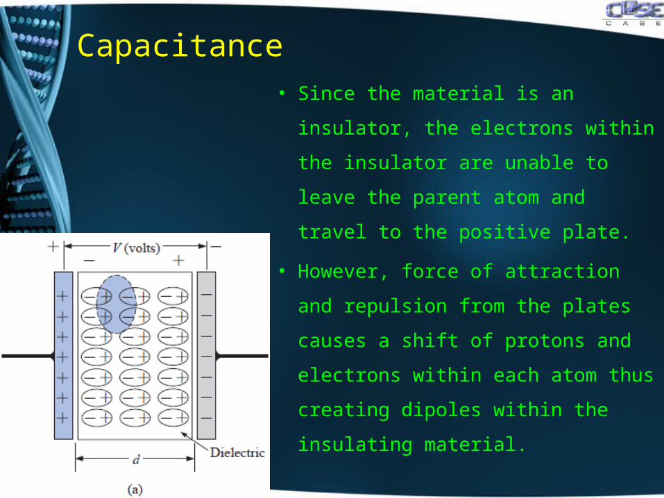
• Since the material is an insulator,
the electrons within the insulator are
unable to leave the parent atom and
travel to the positive plate.
• However, force of attraction and
repulsion from the plates causes a
shift of protons and electrons within
each atom thus creating dipoles
within the insulating material.
Capacitance
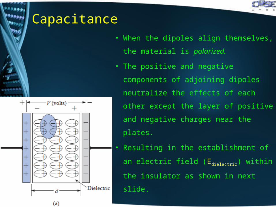
• When the dipoles align themselves,
the material is polarized.
• The positive and negative
components of adjoining dipoles
neutralize the effects of each other
except the layer of positive and
negative charges near the plates.
• Resulting in the establishment of an
electric field (Edielectric) within the
insulator as shown in next slide.
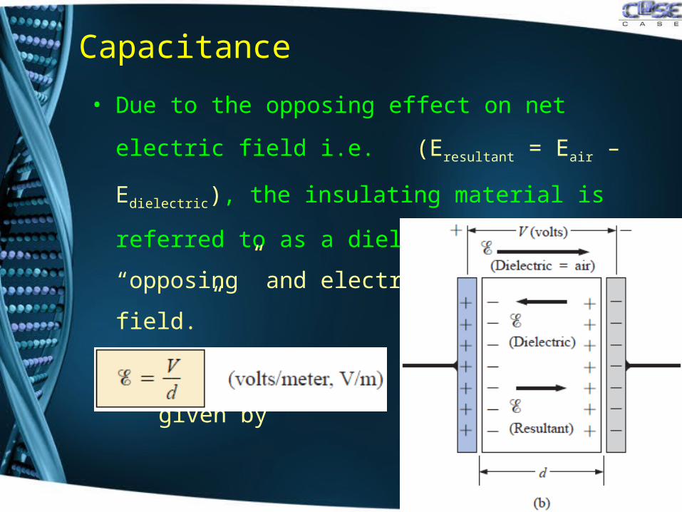
Capacitance
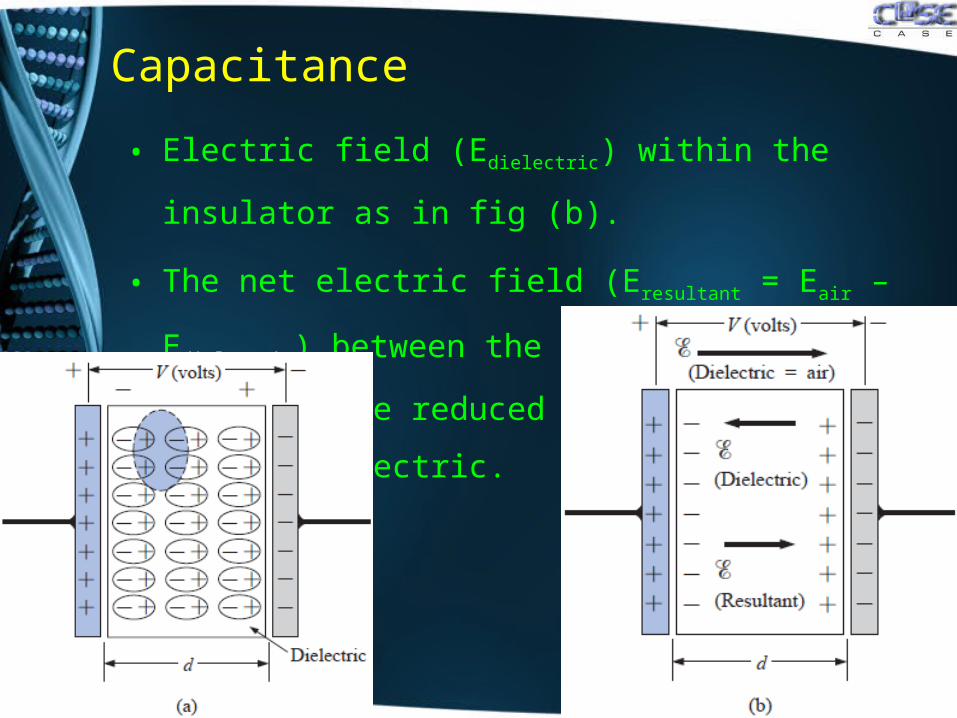
• Electric field (Edielectric) within the insulator as in fig (b).
• The net electric field (Eresultant = Eair – Edielectric) between
the plates would therefore be reduced due to the
insertion of the dielectric.
Capacitance
• Due to the opposing effect on net electric field i.e.
(Eresultant = Eair – Edielectric), the insulating material is
referred to as a dielectric; di for “opposing” and electric
for “electric field.”
• Where electric field is
given by
Capacitance
• Calculating Electric Field between the two plate:
• From Gauss’s law, Φ = qin / ϵ
• But qin = σ A
• Thus we have, Φ = σ A / ϵ
• But Q = σ A
• Thus, we have Φ = Q / ϵ
• But also we know, Φ = EA
• Therefore E A = Q / ϵ
• Thus electric field between plates is E = Q / A ϵ
Capacitance
• Calculating permittivity of dielectric:
• From Gauss’s law, Φ = qin / ϵ
• But qin = σ A
• Thus we have, Φ = σ A / ϵ
• Also Φ = E A
• Therefore E A = σ A / ϵ
• or E = σ / ϵ
• Thus permittivity is given by ϵ = σ / E
• Measured in Farads / meter (F/m)
Capacitance
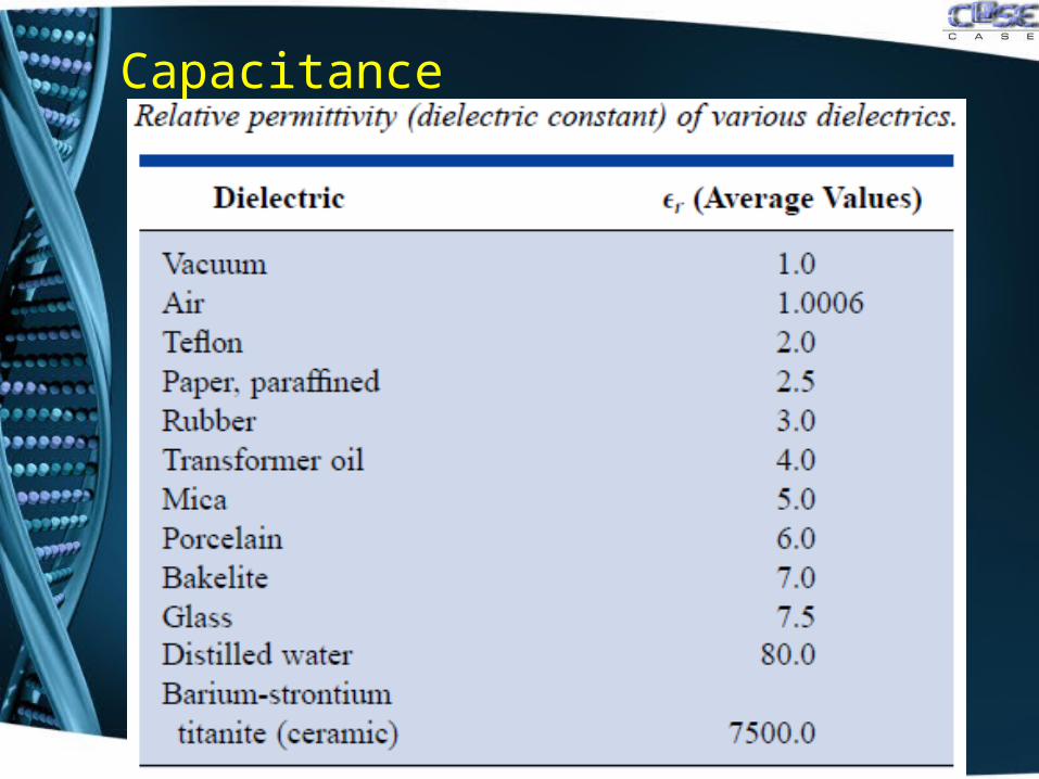
• The ratio of the flux density to the electric field intensity in
the dielectric is called the permittivity of the dielectric:
ϵ = σ / E
• For a vacuum, ϵ (denoted by ϵo) is 8.85 x 10⁻¹² F/m.
• The ratio of the permittivity of any dielectric to that of a
vacuum is called the relative permittivity ϵr. ϵr = ϵ / ϵo
• The relative permittivity ϵr is a dielectric constant and
dimensionless quantity, it simply compares the
permittivity of the dielectric to that of air. ϵ = ϵr ϵo
Capacitance
Capacitance
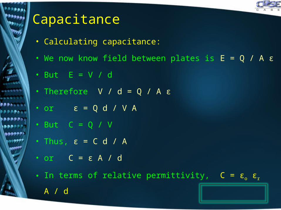
• Calculating capacitance:
• We now know field between plates is E = Q / A ϵ
• But E = V / d
• Therefore V / d = Q / A ϵ
• or ϵ = Q d / V A
• But C = Q / V
• Thus, ϵ = C d / A
• or C = ϵ A / d
• In terms of relative permittivity, C = ϵo ϵr A / d
Capacitance
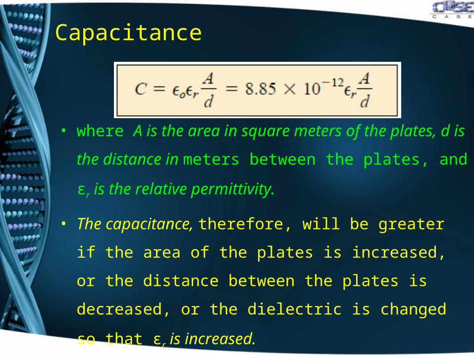
• where A is the area in square meters of the plates, d is
the distance in meters between the plates, and ϵr is the
relative permittivity.
• The capacitance, therefore, will be greater if the area of
the plates is increased, or the distance between the
plates is decreased, or the dielectric is changed so that
ϵr is increased.
Capacitance
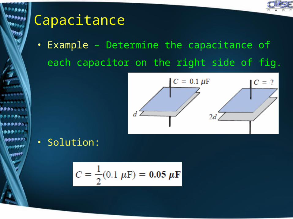
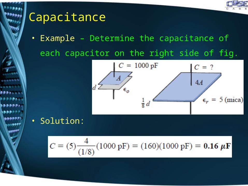
• Example – Determine the capacitance of each capacitor
on the right side of fig.
• Solution:
Capacitance
• Example – Determine the capacitance of each capacitor
on the right side of fig.
• Solution:
Capacitance
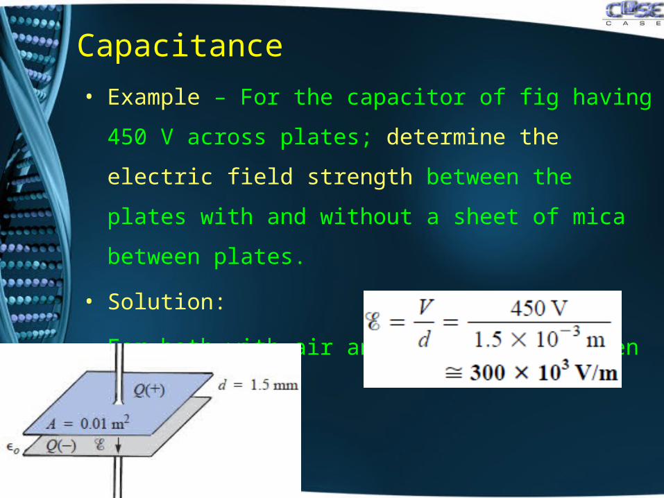
• Example – For the capacitor of fig having 450 V across
plates; determine the electric field strength between the
plates with and without a sheet of mica between plates.
• Solution:
• For both with air and mica sheet between plates;
Capacitance
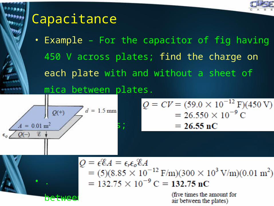
• Example – For the capacitor of fig having 450 V across
plates; find the charge on each plate with and without a
sheet of mica between plates.
• Solution: For air between
plates;
• . For mica sheet between
plates;
Capacitance
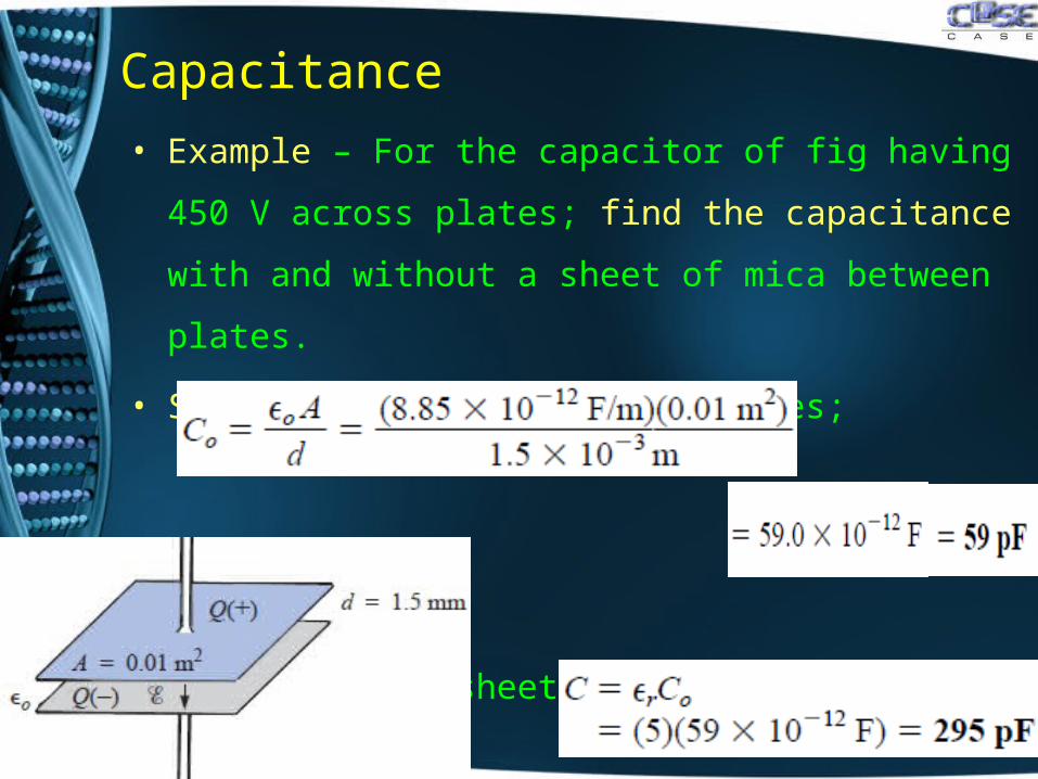
• Example – For the capacitor of fig having 450 V across
plates; find the capacitance with and without a sheet of
mica between plates.
• Solution: For air between plates;
• . For mica sheet between
plates;

Dielectric Strength
• For every dielectric, if potential difference exceeds
certain limits, it will break the bonds within the dielectric
and cause current to flow.
• The voltage required per unit length (electric field
intensity) to establish conduction in a dielectric is an
indication of its dielectric strength and is called the
breakdown voltage.
• A typical example of breakdown is lightning between
clouds and earth with air as its dielectric.
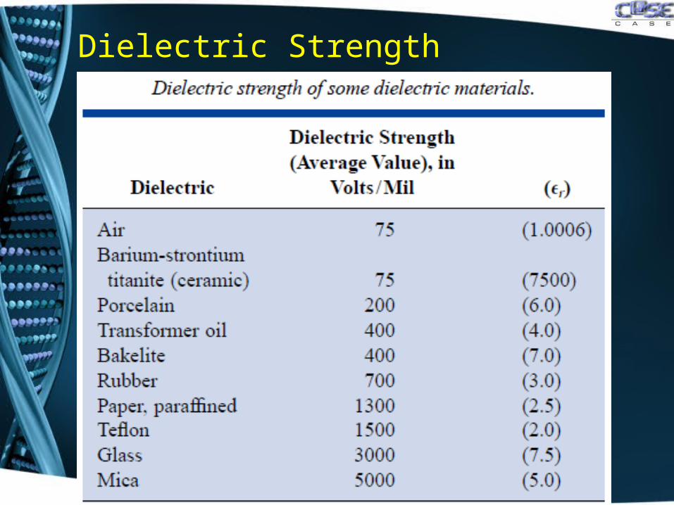
Dielectric Strength
Dielectric Strength
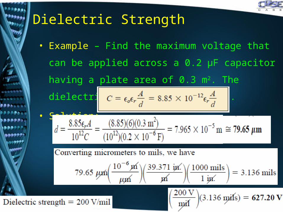
• Example – Find the maximum voltage that can be
applied across a 0.2 μF capacitor having a plate area
of 0.3 m2. The dielectric is porcelain (200V/m).
• Solution:
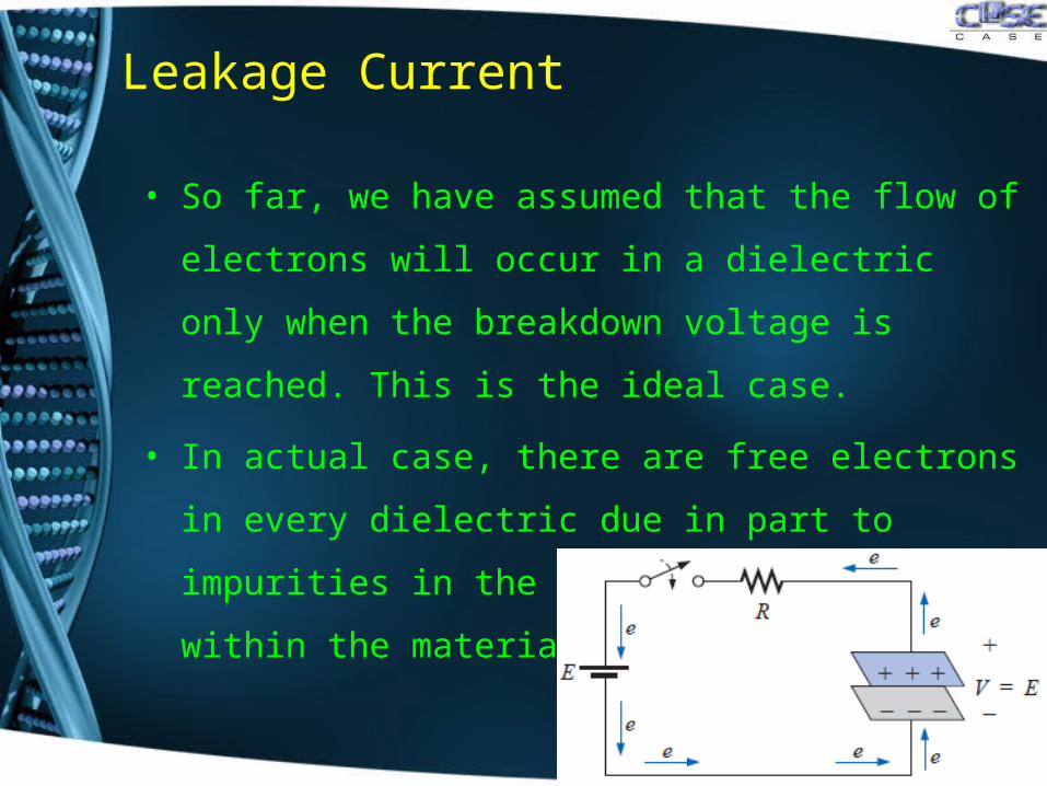
Leakage Current
• So far, we have assumed that the flow of electrons
will occur in a dielectric only when the breakdown
voltage is reached. This is the ideal case.
• In actual case, there are free electrons in every
dielectric due in part to impurities in the dielectric and
forces within the material itself.
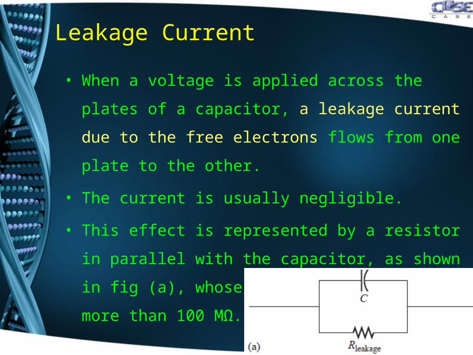
Leakage Current
• When a voltage is applied across the plates of a
capacitor, a leakage current due to the free electrons
flows from one plate to the other.
• The current is usually negligible.
• This effect is represented by a resistor in parallel with
the capacitor, as shown in fig (a), whose value is
typically more than 100 MΩ.
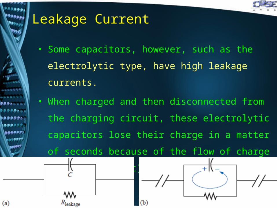
Leakage Current
• Some capacitors, however, such as the electrolytic
type, have high leakage currents.
• When charged and then disconnected from the
charging circuit, these electrolytic capacitors lose their
charge in a matter of seconds because of the flow of
charge (leakage current) from one plate to other fig (b).
Summary / Conclusion
• Introduction
• Electric Field
• Capacitance
• Dielectric Strength
• Leakage Current