Embed Size (px)
Citation preview

© Deakin University 1
Electricity
Introduction This topic explores the key concepts of electricity as they relate to: • static electricity • current electricity • higher order models of electric circuits • household electricity • electricity and magnetism.
Key concepts of electricity The activities in this topic are designed to explore the following key concepts:
Static electricity • Charged objects will attract uncharged objects. • Objects can be charged by rubbing. • Some materials are charged more easily than others. • An object becomes charged when it loses or gains electrons. • Objects can carry either a positive or negative charge, depending on what
they are made of and what they are rubbed with. • A negatively charged object has gained electrons; a positively charged
object has lost electrons. • Like charges repel; unlike charges attract. • Charged objects will discharge over time as charge leaks to the atmosphere. • Charge can move about on conductors, but not very much on insulators. • Sparks are the movement of electrons through the air from one object to
another. Lightning is a sparking effect. • Earthing is where charge is shared between a charged object and a large
conductor (usually the ground). • We measure the quantity of charge with a unit called a ‘coulomb’.
Current electricity • Electric current (measured in amperes) is the flow of electric charge
(measured in coulombs) around a circuit. • A complete circuit is needed for an electric current.

2 S C I E N C E C O N C E P T S : Y E A R S 5 – 1 0 E L E C T R I C I T Y © Deakin University
• Conventional current comes out of the positive terminal of a battery and flows back into the negative terminal, whereas electrons actually flow the other way.
• Switches stop the flow of current. • The current out of the battery from the positive terminal is the same as that
entering the battery through the negative terminal. Current is not diminished around a circuit.
• Metals conduct electric current; most other substances are insulators. • The voltage (measured in volts) of a battery is the energy (measured in
joules) supplied to each unit of charge (measured in coulombs). • Electric circuits involve the transformation of electrical energy into other
forms such as heat, light and movement. • The amount of energy given to each unit of charge diminishes around the
circuit.
Household electricity • Household electricity runs on 240 volts alternating voltage and current. • A complete circuit includes the generator, wires and the appliance in the
home. • A fuse or circuit-breaker breaks a circuit when too much current passes
through it. • Households have a number of parallel circuits each with their own fuse or
circuit-breaker. • The wires from the generator are called the ‘active’ and the ‘neutral’. A
third wire, the ‘earth’, is connected to the neutral wire and the ground. • The earth wire is not normally part of the circuit. It becomes part of the
circuit if it comes in contact with the active wire. • Physically touching an active wire completes a circuit where the current is
passed from the active wire, through the person, the ground and then back to the neutral wire.
Students’ alternative conceptions of electricity Research into students’ ideas about this topic has identified the following non-scientific conceptions: • The electricity companies supply electrons for your household current. • We pay electricity companies for power. • ‘Static’ and ‘current’ electricity are two types of electrical energy. • ‘Electricity’ is used up in electric circuits. • Charge is used up in electric circuits. • Energy is used up in electric circuits. • More devices in a series circuit mean more current because devices ‘draw’
current. • Electrical power is the same as electrical energy. • Electricity means the same thing as current, or voltage, or energy.

© Deakin University S C I E N C E C O N C E P T S : Y E A R S 5 – 1 0 E L E C T R I C I T Y 3
• Batteries store, and supply, electrons or ‘electricity’ to the electric circuit. • A wire from a battery to a bulb is all that is needed for the bulb to light up. • The electrical energy in a circuit flows in a circle. • Electric current is a flow of energy. • The stuff that flows through wires is called ‘electric current’. • Electrons travel at, or near, the speed of light in the wires of an electric
circuit. • Voltage flows through a circuit. • Voltage is energy. • High voltage by itself is dangerous. • Electrons move by themselves. • Current is the same as voltage. • A conductor has no resistance. • The bigger the battery, the more voltage. • Batteries create energy out of nothing. • Alternating current (AC) charges move all the way around a circuit and all
the way back. • AC voltage and current remains constant as in direct current (DC) circuits.
Resources Activities to Explore Static Electricity http://www.mos.org/sln/toe/staticmenu.html Various activities relates to the phenomenon of static electricity.
‘Electricity’ misconceptions in textbooks http://www.amasci.com/miscon/elect.html This site outlines a number of misconceptions students and adults have about the topic of electricity.
Experiments with Static Electricity http://www.school-for-champions.com/science/experiments/expstatic.htm Contains a series of experiments related to static electricity effects.
Exploratorium Science Snacks: ‘Snacks about electricity’ http://www.exploratorium.edu/snacks/iconelectricity.html Contains a number of interesting experiments. Full details of each experiment are given.
Sparks and Lightning http://www.eskimo.com/~billb/tesla/spark.html

4 S C I E N C E C O N C E P T S : Y E A R S 5 – 1 0 E L E C T R I C I T Y © Deakin University
Introduction to electricity Everyday meanings of electrical terms Everyday talk about electricity and electrical appliances is markedly different from scientific talk about them. Terms such as ‘electricity’, ‘current’, ‘voltage’ and ‘power’ are used in everyday talk, but with significantly different meanings than in science. Whereas scientific terms such as ‘power’, ‘electricity’, ‘current’ and ‘energy’ have specific well-defined meanings, in the community these terms are often used interchangeably. This creates misunderstandings and misconceptions about phenomena related to electricity.
In learning a new topic, students should become aware of their current understanding. This can be done through a brainstorming activity and could be followed up by constructing a concept map. During the brainstorming session, where students use scientific terms such as ‘current’ or ‘voltage’, have them explain to the class what they understand by these terms.
Static electricity versus current electricity Static electricity is the separation of electric charges that creates phenomena such as lightning and shocks that you get when walking on carpet or touching a doorknob. Static electricity is not as relevant to our lives as current electricity. Current electricity is the motion of electric charges and affects many aspects of our lives such as the operation of electrical goods in the home (lighting, toasters, refrigerators, lawn mowers). Current electricity plays an important part in communication, through telephones, television and computers, and in manufacturing goods (most industries rely on electric motors).
Static electricity As well as lightning, a number of other effects that we come across in our daily lives can be attributed to static electricity. Such effects include nylon clothing sticking to you when dressing or undressing, shocks from cars or trampolines, and hair sticking out when combed. Have you ever tried to fill a beanbag with polystyrene balls?
Before exploring scientific explanations for static electricity effects, try out the following activities. Students can build up a series of observations, and then apply the theory.
The following static electrical effects work best when the weather is dry. If the weather is humid the equipment should be dried with a heater or hair drier. In your journal record your observations and try to make plausible explanations for the effects. The explanations for these effects are given later in this section.
A C T I V I T Y: E L E C T R I C A L T E R M S

© Deakin University S C I E N C E C O N C E P T S : Y E A R S 5 – 1 0 E L E C T R I C I T Y 5
You will need: • paper • plastic rulers • combs • pens • PVC strips • perspex strips • glass rods • balloons • plastic wrap • various materials for rubbing the object such as wool, fur, silk, cotton, hair,
plastic wrap, etc. • aluminium foil.
Rip up small pieces of paper. Observe the effects when first you bring unrubbed objects near the paper and secondly when you bring the objects near the paper after rubbing with material. What combinations of materials and objects produce the greatest effect? Try picking up small pieces of aluminium foil. Do you achieve different effects?
Rub an inflated balloon vigorously with a piece of wool. Now hold the balloon up against a wall. It will stick to it. It will also stick to your hand, table or even the ceiling. Why?
Rub two inflated balloons vigorously with wool and bring them near each other. What do you observe? Now rub one balloon with wool and the other with plastic wrap or silk and bring them near each other. What do you observe?
Explanations for static electrical effects All matter is composed of small particles called ‘atoms’ that consist of a positively charged centre and negatively charged electrons, some of which are only loosely held by the atom. When two objects come into contact with each other, electrons can transfer from one object to another. This transfer of electrons, which can be heightened through rubbing the materials together, occurs when one of the objects has a propensity to attract electrons from the other object. If an object gains extra electrons it is negatively charged, but if it loses electrons it becomes positively charged. For example, when PVC is rubbed with wool, electrons are transferred from the wool to the PVC. In this circumstance the PVC gains a negative charge while the wool gains a positive charge. However, if perspex is rubbed with wool, electrons are transferred to the wool leaving the perspex positively charged and the wool negatively charged.
Electric charge and subatomic particles Electric charge is a property of the subatomic particles known as ‘protons’ and ‘electrons’. Protons and electrons are some of the main constituents of atoms that make up matter. Electrons have a negative charge, whereas protons have a positive charge. The amount of charge on each particle is the same. These two
A C T I V I T Y: C H A R G E D O B J E C T S

6 S C I E N C E C O N C E P T S : Y E A R S 5 – 1 0 E L E C T R I C I T Y © Deakin University
particles are responsible for all electrical behaviour. A simple model of the atom is shown in Figure 1. Notice that the protons are contained within a central nucleus (other particles, called ‘neutrons’ with a neutral charge, are also there) and electrons are free to move in the space outside the nucleus.
As all matter is made up of atoms, and atoms contain protons and electrons, then all matter can be considered electrical. Most atoms have the same number of electrons as protons, so we can consider the atom to be electrically neutral as the total negative charge of the electrons cancels the total positive charge of the protons. However, atoms can lose or gain electrons quite easily (gaining and losing protons is quite difficult) and so an atom that has more electrons than it has protons will have a net negative charge, and an atom that has fewer electrons than it has protons has a net positive charge. Atoms that have lost or gained electrons are called ‘ions’.
The smallest amount of electric charge is that found on the electron or proton. This amount of charge is called an ‘elementary charge’. However, in our everyday experiences with electrical phenomena we are dealing with many, many elementary charges, so another, more convenient, unit is used. This is called a ‘coulomb’ (it has a symbol, C). One coulomb equals 1 600 000 000 000 000 000 elementary charges—quite a large number indeed!
An uncharged object still contains atoms that have both positive and negative charges but they are equal in number and so the overall effect is a neutralising one. This is why uncharged objects are sometimes described as having an overall neutral charge. A negatively charged object has an excess of negative charges to the positive charges in the atoms.
When objects become charged they may repel or attract other charged objects (such as the two balloons in the activity Charged objects). In addition, charged objects may attract uncharged objects (for example, picking up bits of paper in the activity). Charged objects that repel or attract can be explained by the rule that ‘same charged objects repel each other and oppositely charged objects attract each other’. This is shown in Figure 2.
F I G U R E 1 : M O D E L O F T H E ATO M

© Deakin University S C I E N C E C O N C E P T S : Y E A R S 5 – 1 0 E L E C T R I C I T Y 7
Like charges repel Unlike charges attract
When charged objects attract uncharged objects, such as when a negatively charged balloon attracts paper, the negatively charged balloon repels some of the electrons in the paper. This will result in a redistribution of charges in the paper so that one side of the paper is slightly more negative than the other side. The net effect is that the paper is attracted to the balloon. The principle is the same with the balloon attracting an uncharged wall. This effect can be seen in Figure 3.
Charged balloon not nearby
Charged balloon attracted to a wall
Charged balloon nearby
In the activity Charged objects you may have found that while the plastic ruler or balloon could attract pieces of paper, the material that was used to rub the objects could not. Where there is a transfer of electrons, one object gets a negative charge and the other object gets an equal but opposite positive charge. In the case of the plastic ruler, its surface is smooth and so the charge is concentrated over a small area. The rubbing material, wool, has many fibres and so the charge is distributed over a wider area. The greater the concentration of charge, the bigger the effect it can produce.
You will need: • a plastic strip • a test tube • a test-tube stand • Blu-Tack • a needle, or thin firm wire • a cork • combinations of objects (plastic ruler, pen, comb, PVC or perspex strip, glass
rod, balloon) • combinations of materials (rod, fur, silk, cotton, hair, plastic wrap).
Make a charge detector as shown in the figure Charge tester. If you rub the plastic strip with wool it will gain a negative charge. By bringing other charged objects nearby, the PVC strip will either be repelled or attracted.
F I G U R E 2 : F O R C E S O N C H A R G E D B A L L O O N S
F I G U R E 3 : AT T R A C T I V E F O R C E S
A C T I V I T Y: M A K I N G A C H A R G E D E T E C TO R
8 S C I E N C E C O N C E P T S : Y E A R S 5 – 1 0 E L E C T R I C I T Y © Deakin University
Use different combinations of objects and materials. Bring the charged object near your charge detector. What can you deduce about what charge the object contains? Make a list.
You will need: • two balloons • pepper • a spray bottle • water • a piece of plastic • wool, fur or other material for rubbing.
Work out a way of measuring how strong the charge is on a balloon or piece of plastic. Perhaps you could measure the distance the balloon is above the grains of pepper before it starts to jump, or the distance between two ‘unfriendly’ charged balloons held together.
Investigate the method of rubbing that gives the most charge. Measure the strength of charge each minute to see how quickly it is lost.
Charge the balloon, and then spray around it with a fine mist of water. How much does this reduce the charge? Does this tell you anything about the effect of humidity on charge?
Electric charge, conductors and insulators Once an object is charged (that is, it has an overall negative or positive charge because of an excess or deficiency of electrons), electrical effects can be observed. In some materials (e.g. metals) electrons can move freely through the material, whereas in other materials (e.g. ceramics) electrons are not free to move very much. Materials in which electrons move freely are called ‘conductors’ and materials in which electrons do not move as freely are called ‘insulators’ (there are some materials, silicon for example, that do not fit in either category and are termed ‘semiconductors’; such materials are important in electronics and the operation of computers).
Table 1 gives a listing of some common conductors and insulators.
F I G U R E : C H A R G E T E ST E R
A C T I V I T Y: L O S I N G C H A R G E

© Deakin University S C I E N C E C O N C E P T S : Y E A R S 5 – 1 0 E L E C T R I C I T Y 9
Electrons are transferred by rubbing objects that are insulators or conductors. Whereas the concentration of charge remains in the area of rubbing for the insulator, it spreads throughout the conductor. If you are holding a conductor while rubbing it, then not only does the charge distribute itself over the conductor, it is also shared by your body. For this reason, to observe any static electrical effects with conductors they must first be insulated (that is, be held by an insulator).
In the activity Losing charge the water droplets act as conductors and, when they come into contact with the balloon, some of the charge will be transferred to the water. As the water droplets fall off the balloon (they are also repelled, as they now have the same charge as the balloon) they take charge with them. In this way the balloon becomes discharged. On a humid day a similar process occurs with invisible water droplets. The droplets are initially attracted to the balloon (like the pieces of paper) but upon touching the balloon, charge is shared between the balloon and the droplets. At this point they both have the same charge and the droplets are repelled, taking some of the charge with them. This principle is the same as that causing small aluminium pieces to be at first attracted to a charged object and then repelled.
You will need: • aluminium foil • thread • a balloon or a plastic ruler.
Suspend a small ball of scrunched-up aluminium foil from a thread. Try the following sequence of activities and see if you can explain what is happening in terms of the charge on the aluminium ball.
Bring a charged balloon or plastic ruler close to the aluminium ball. The ball is attracted even though it is uncharged. Let the ball touch the balloon or ruler. What happens? Why?
Take the balloon or ruler away and bring your finger close to the ball. What happens? Why? Touch the ball. Now bring your finger close again. Bring the balloon or ruler close again. The ball is uncharged! How did that happen?
With the balloon or ruler close to the uncharged ball but not touching it, touch the ball with your finger and then let go. Does the attraction to the balloon or ruler change? What do you suppose happened when you touched the ball? Take the
T A B L E 1 : C O N D U C T O R S A N D I N S U L A T O R S
Conductors
Good Poor
Insulators
metals (gold and silver, the best)
carbon as graphite (pencil lead)
water
human body
Earth
rubber
plastics
dry air
ceramics
glass
A C T I V I T Y: P L AY I N G D E T E C T I V E W I T H C H A R G E S

10 S C I E N C E C O N C E P T S : Y E A R S 5 – 1 0 E L E C T R I C I T Y © Deakin University
balloon or ruler away. Bring your finger close to the ball. Can you explain what you observe now?
You might like to test your ideas by hanging two identical aluminium balls side by side, but not touching, and trying different sequences with them.
Let us assume that the balloon or ruler is initially positively charged. The ball is initially attracted as there is charge redistribution on the ball; negative charges in the ball move to the near side of the balloon while positive charges move to the other side.
• When the positively charged balloon touches the ball, positive charge evenly distributes itself over the ball from the balloon. The balloon and the ball are now both positively charged and so will repel each other.
• If you now bring your finger to the ball (now positively charged), it will attract the ball. There is charge redistribution in your finger.
• If you touch the ball, positive charge flows from the ball into the larger conductor, which is your body. There will be very little positive charge left on the ball (it has been ‘earthed’). The positive charge then moves from you into the ground, so you are also left without a charge.
• Now, if you are touching the ball when the positively charged balloon is brought nearby, there is charge redistribution on the ball. However, as you are holding the ball, negative charges from you and the ball will move near the balloon while positive charges will flow into your finger. If you now let go of the ball it will be left with a negative charge. The negatively charged ball will attract the positively charged balloon.
• If you now bring your finger to the negatively charged ball, it will attract your finger (charge redistribution).
Sparks and lightning Sparks are produced when there is a sudden movement of charge, usually through the air, from one material to another. Lightning is just a sparking effect. Clouds gain electric charge in certain atmospheric conditions (the exact scientific reason is unknown). Such clouds can come near oppositely charged clouds with the result that electrons will travel from one cloud to another. Alternatively, the electrons can be attracted to objects on the ground in the same way that pieces of neutrally charged paper are attracted to the comb. However, electrons are more attracted to metal objects as, being conductors, the charge separation that is induced by the charged cloud is far greater than can be obtained in an insulator. If the cloud is negatively charged then electrons travel to the ground, but if the cloud is positively charged electrons travel from the ground to the cloud.
Earthing Sparking effects can occur in situations other than lightning. Planes and cars often build up large charges due to the frictional effects of moving at speed through the air. Such effects can be quite dangerous, especially in situations where the plane or car is being refuelled. To offset the possibility of sparking in a car, it is continually earthed. Earthing is a process by which a charge on a

© Deakin University S C I E N C E C O N C E P T S : Y E A R S 5 – 1 0 E L E C T R I C I T Y 11
material is shared with a much larger object, like Earth. In the case of the car, any charge that builds up is shared with the ground. As the ground is much larger than the car, most of the charge moves away from the car. The conducting path on most cars is through the tyres (the rubber is impregnated with a conducting material) but in some cars a strip of conductor underneath the car produces a conducting path from the car to the ground.
In the case of the plane, earthing occurs upon landing. A refueller touches the plane with a conductor (attached to the ground) to ensure the plane is fully discharged before refuelling the plane. Powerlines and poles and tall buildings are particularly susceptible to lighting strikes (these are objects that are usually closest to the charged clouds), and so many are earthed (or grounded) by having a metal conductor that is connected from the top of the pole or building to several metres within the ground. If lightning hits the metal conductor then charge flows safely into Earth, which, being a very large conductor, spreads the charge over a wide area.
More static electricity effects You will need: • pieces of paper • cigarette ash • a plastic comb • nylon or wool • a cup of puffed rice • aluminium foil.
Charge a comb by rubbing with wool or nylon. Bring your charged comb near small pieces of paper or cigarette ash. Thrust your charged comb into a cup of puffed rice and remove.
Observe what happens to the paper, ash and rice, particularly some moments after jumping onto the comb. Why? Observe and explain the effects of placing a charged comb near small pieces of aluminium foil.
You will need: • a sheet of paper • wool or nylon or fur • plastic wrap.
Hold a piece of dry paper against a wall with one hand, and rub it briskly with the other hand for a few seconds. On a dry day the paper will stick to the wall for hours. Pull the paper completely away from the wall and you will hear crackling. Why?
A greater charge can be placed on the paper using other materials; try fur, wool, nylon and plastic wrap. Try placing some celluloid or plastic wrap against the wall and rub it with the materials.
A C T I V I T Y: T R I C K S W I TH A C O M B
A C T I V I T Y: C H A R G E D P I E C E S O F PA P E R
12 S C I E N C E C O N C E P T S : Y E A R S 5 – 1 0 E L E C T R I C I T Y © Deakin University
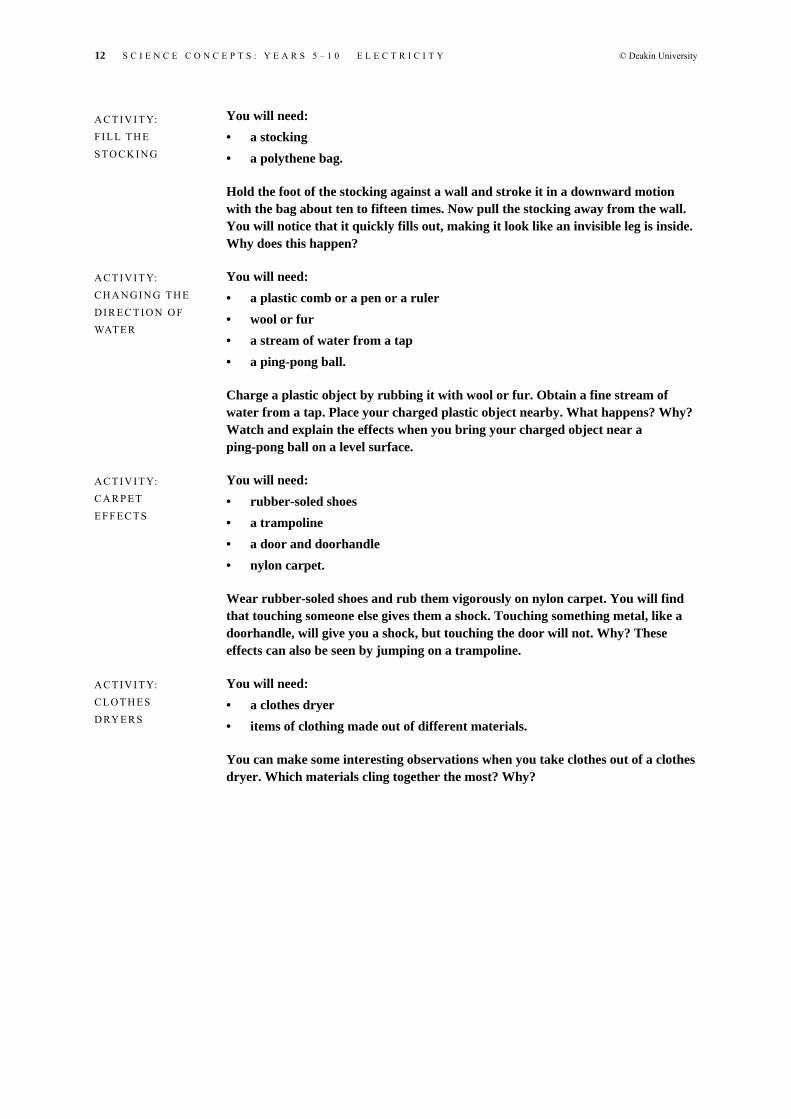
You will need: • a stocking • a polythene bag.
Hold the foot of the stocking against a wall and stroke it in a downward motion with the bag about ten to fifteen times. Now pull the stocking away from the wall. You will notice that it quickly fills out, making it look like an invisible leg is inside. Why does this happen?
You will need: • a plastic comb or a pen or a ruler • wool or fur • a stream of water from a tap • a ping-pong ball.
Charge a plastic object by rubbing it with wool or fur. Obtain a fine stream of water from a tap. Place your charged plastic object nearby. What happens? Why? Watch and explain the effects when you bring your charged object near a ping-pong ball on a level surface.
You will need: • rubber-soled shoes • a trampoline • a door and doorhandle • nylon carpet.
Wear rubber-soled shoes and rub them vigorously on nylon carpet. You will find that touching someone else gives them a shock. Touching something metal, like a doorhandle, will give you a shock, but touching the door will not. Why? These effects can also be seen by jumping on a trampoline.
You will need: • a clothes dryer • items of clothing made out of different materials.
You can make some interesting observations when you take clothes out of a clothes dryer. Which materials cling together the most? Why?
A C T I V I T Y: F I L L T H E S TO C K I N G
A C T I V I T Y: C H A N G I N G TH E D I R E C T I O N O F WAT E R
A C T I V I T Y: C A R P E T E F F E C T S
A C T I V I T Y: C L O T H E S D RY E R S

© Deakin University S C I E N C E C O N C E P T S : Y E A R S 5 – 1 0 E L E C T R I C I T Y 13
Current electricity Current electricity has a great influence on our lives, and an understanding of the basic processes is important for a scientifically literate society. We (including the scientific community) cannot directly see what goes on when, for example, a switch is turned on in a torch and the bulb lights up. From a scientific perspective, we can only construct models that help explain the processes that we observe taking place. We will use several models, each with their own specific purpose, to explain some aspect of current electricity. These models will provide you with a means to understand electrical terms from a scientific perspective.
You will need: • a battery • a bulb • sticky tape • connecting wire.
A battery and bulb can be found in a torch (a torch with a large 6 V battery and a bulb is ideal). The voltage written on the battery must be about the same as that written on the bulb. If your torch has a number of batteries you need to tape them together (head to tail) leaving the ends free.
Arrange the battery, bulb and wire(s) in such a way as to light the bulb. In your journal write down your experiences, describing your successes and your failures. Can you describe the processes by which the bulb lights up?
You will need: • the worksheet provided • a battery • a globe • a piece of wire.
An alternative to the Getting a bulb to light activity is to use the following worksheet. First, predict which of the arrangements on the worksheet showing a battery, bulb and wire on the worksheet will make the bulb light up. Once you have made your predictions, have a classroom discussion of the main ideas before you actually test out your ideas.
The key idea to this activity is that a complete conducting path loop is required for the bulb to light up.
A C T I V I T Y: G E T T I N G A B U L B TO L I G H T
A C T I V I T Y: W O R K S H E E T
14 S C I E N C E C O N C E P T S : Y E A R S 5 – 1 0 E L E C T R I C I T Y © Deakin University
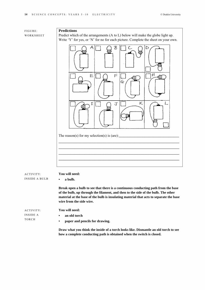
Predictions Predict which of the arrangements (A to L) below will make the globe light up. Write ‘Y’ for yes, or ‘N’ for no for each picture. Complete the sheet on your own.
The reason(s) for my selection(s) is (are):___________________________________
______________________________________________________________________
______________________________________________________________________
______________________________________________________________________
______________________________________________________________________
You will need: • a bulb.
Break open a bulb to see that there is a continuous conducting path from the base of the bulb, up through the filament, and then to the side of the bulb. The other material at the base of the bulb is insulating material that acts to separate the base wire from the side wire.
You will need: • an old torch • paper and pencils for drawing.
Draw what you think the inside of a torch looks like. Dismantle an old torch to see how a complete conducting path is obtained when the switch is closed.
F I G U R E : W O R K S H E E T
A C T I V I T Y: I N S I D E A B UL B
A C T I V I T Y: I N S I D E A TO R C H

© Deakin University S C I E N C E C O N C E P T S : Y E A R S 5 – 1 0 E L E C T R I C I T Y 15
Energy consumption model Let’s begin by imagining an electric circuit in a torch. Inside the torch is a battery (sometimes several), connecting wire that is a conductor (sometimes this is a flat strip of metal), a switch and a light bulb. Figure 4 is a circuit diagram showing each of these components. The symbols used for each component are standard for most science textbooks. The bulb lights up when the switch is closed.
We can describe the process as energy transference from the battery to the bulb via the wires. The concept of energy is very difficult to understand in science. For our purposes, energy can be understood in terms of matter with energy having the ability to cause change or movement in other matter. Energy can come in different forms, for example, kinetic energy, chemical energy, heat energy, electrical energy and light energy. Some examples of these energy types are: • Kinetic energy: a moving car has kinetic energy that has the ability to drag
along a trailer. Any object that is moving is considered to have kinetic energy.
• Heat energy: a hot cup of tea has heat energy that has the ability to raise the temperature of the cold milk that is added. Heat energy is transferred from hot objects to cooler objects.
• Potential energy: a stretched bowstring has potential energy that has the ability to fire an arrow.
• Chemical energy: petrol has chemical energy that has the ability, when lit, to push a cylinder in a car engine. Food has chemical energy that can convert into kinetic energy in the motion of blood and limbs in our bodies. The energy content of food is quite often provided as information on food packaging, particularly breakfast cereals.
• Electrical energy: electric charges flowing in a wire near a magnet have the ability to vibrate the wire, as in a loud speaker.
• Light energy: considered to be pure energy, light energy has the ability to raise the temperature of your skin while you are lying in the sun.
F I G U R E 4 : C I R C U I T D I AG R A M O F A TO R C H

16 S C I E N C E C O N C E P T S : Y E A R S 5 – 1 0 E L E C T R I C I T Y © Deakin University
Energy is never created or destroyed, but can transform from one type of energy to another and be transferred from one object to another. For example, a ball that is thrown against a wall has received kinetic energy from an arm that had potential energy. The potential energy of the arm was transformed from chemical energy in the food that the person ate. The chemical energy in the food was transformed from light energy from the sun. The ball, upon hitting the wall, converts kinetic energy into potential energy where it stops (it gets squashed against the wall). This potential energy is then converted back into kinetic energy in the rebounding ball. The ball is then caught, so the kinetic energy of the ball is converted to kinetic energy of the particles of the hand which is noticeable by a rise in temperature of the hand.
In the case of our torch circuit, chemical energy in the battery is converted to electrical energy that is transferred by the wires to the bulb where it is converted into heat energy and light energy in the filament. In the battery the conversion of chemical energy to electrical energy takes place through a chemical reaction. Once the reaction is complete, the battery is considered dead.
This model of energy transference does not explain what carries the electrical energy or why you require two wires or a connecting loop from the positive terminal of the battery to the negative terminal of the battery. However, this model tells us that when you turn the switch on in your home, the appliance that is connected to the switch is converting energy. This energy came from a generator in Gippsland or Snowy River. This is what we pay for: energy (not electricity, not power). The scientific unit of energy is the ‘joule’ (J).
The electrical energy we pay for is not in units of joules but in units called ‘kilowatt hours’ (kW.h). In terms of joules, 1 KW.h is equivalent to 3.6 million joules or 3.6 megajoules (MJ).
‘Power’ is a term that is quite often used inappropriately in common language. For example, ‘we received our electricity power bill today that showed we used a lot of power last quarter’. In science, power is actually the rate at which energy is used up. Power is measured in watts (W), so that a 100 W light globe will use up 100 J of energy for every second that it is on.
Each electrical appliance in your home, whether a stove, heater, light bulb or television set, has a power rating usually marked on the appliance in some way.
Determine the power rating of several different appliances used in your home. Tabulate the power ratings in your journal as in the table Power ratings.
Determine the approximate number of hours of usage of each item in a given week. If you now multiply the usage (in hours) by the power rating (in watts) and then divide by 1000 you obtain the amount of energy the appliance uses in a week. If the power rating is already in kilowatts (kW), you only need to multiply the power rating by the usage to obtain the energy in units of kW.h.
A C T I V I T Y: E N E R G Y A N D P O W E R I N T H E H O M E
Appliance Power rating (W) Usage (hours) Energy (kW.h)
Light bulb 100 35 100 × 35/1000 = 0.35
T A B L E : P O WE R R A T I N G S

© Deakin University S C I E N C E C O N C E P T S : Y E A R S 5 – 1 0 E L E C T R I C I T Y 17
Determine which appliances have a high power rating. Which appliances have a high energy usage? Does high power rating mean a high energy usage?
Consider the following examples of energy usage in the household.
Example 1 Let’s assume a unit of energy (1 kW.h) costs 12¢ and we use typical power ratings. Compare the daily cost of four items: • heat bank (4.5 kW) that operates thirteen hours during the day • six lights (6 × 80 W = 480 = 0.480 kW) that operate six hours during the day • dryer (2.0 kW) that operates one hour during the day • television (0.1 kW) that operates five hours during the day.
Now, to calculate the energy usage, the power (in kW) is multiplied by the time (in hours) to give the energy for each item. Multiplying the energy usage by the price per kW.h gives the cost of using the item during the day. The calculations are shown in the table Cost of appliances.
Example 2 Consider a fan heater (5 kW) and a light bulb (100 W = 0.100 kW). If the fan heater was operated for an hour, how long could you operate a the light bulb to produce the same energy output (the same cost to the electrical energy bill)?
The energy used by the fan heater in one hour is 5 kW multiplied by one hour, which equals 5 kW.h. The energy used by the globe in one hour is 0.100 kW multiplied by one hour, giving 0.100 kW.h. To consume the same amount of energy as the heater, the bulb would then need to operate for 5 kW.h divided by 0.100 kW.h, which equals fifty hours.
Various models help us understand how energy is transferred from the battery to the bulb. However, before we can test out different models we need to explore our simple torch circuit a bit more.
You will need: • the worksheet Electric bulb circuits • a number of batteries • bulbs • connecting wire • switches.
For each activity in the worksheet, answer the question asked. Then test your answer by constructing the electric circuits.
T A B L E : C O S T O F A P P L I A N C E S
Item Energy (kW.h) Cost ($)
Heat bank 4.5 × 13 = 58.5 kW.h 58.5 × $0.12 = $7.02
Lights 0.48 × 6 = 2.88 kW.h 2.88 × $0.12 = $0.35
Dryer 2.0 × 1 = 2.0 kW.h 2.0 × $0.12 = $0.24
Television 0.1 × 5 = 0.5 kW.h 0.5 × $0.12 = $0.06
A C T I V I T Y: E L E C T R I C B U L B C I RC UI T S

18 S C I E N C E C O N C E P T S : Y E A R S 5 – 1 0 E L E C T R I C I T Y © Deakin University
1) Does the position of the switch make any difference to lighting the bulb
when the switch gets closed?____________________________________
___________________________________________________________
___________________________________________________________
2) What is the effect on the brightness of the bulbs when more are added to
the circuit?_________________________________________________
__________________________________________________________
__________________________________________________________
3) What is the effect of adding batteries to the brightness of the bulb?_____
__________________________________________________________
__________________________________________________________
4) What is the effect of opening or closing the switch?_________________
__________________________________________________________
__________________________________________________________
W O R K S H E E T: E L E C T R I C B U L B C I R C U I T S

© Deakin University S C I E N C E C O N C E P T S : Y E A R S 5 – 1 0 E L E C T R I C I T Y 19
1) The position of the switch does not make any difference. The bulb will only light when the switch is closed.
2) In circuit (b) the bulbs are less bright than in (a). In circuit (c) the bulbs are the same brightness as the bulb in (a).
3) The bulb in (b) is twice the brightness of the bulb in (a). The bulb in (c) does not light up (the connections in the batteries are incorrect).
4) In (a) when the switch is open the bulbs will not light up. With the switch closed, the bulbs are equally bright. In (b) when the switch is open the lower bulb is lit; when the switch is closed both bulbs are equally bright. In (c) when the switch is open the bulb is lit; when the switch is closed the bulb is not lit. When the switch is closed there is a ‘short-circuit’ arrangement.
It does not matter where the switch is placed in the bulb circuit. The bulb will not light up unless the switch is closed. A conducting path must be formed from the positive terminal of the battery through the bulb(s) back to the negative terminal of the battery for the bulb to light up. Such a path is called an ‘electric circuit’. If there is a discontinuity in the conducting path then an open-circuit situation exists. If only one path exists, it is called a ‘series circuit’ (see Figure 5). There can be more than one conducting path from the positive terminal of the battery to the negative terminal. Such paths are called ‘parallel branches’ of a ‘parallel circuit’ (see Figure 5).
Series circuit (one path) Parallel circuit (multiple paths)
Where more bulbs are added in a series circuit, each bulb is less bright. This means that less energy is being transformed at each bulb. Each bulb in the circuit is about the same brightness. Where more bulbs are added in a parallel circuit, each bulb remains at the same brightness. This means that where more bulbs are added in parallel, more energy is transformed in the circuit. Where more batteries are added to the circuit the bulb will be brighter, therefore more energy is being transformed.
Conventional current model One model used commonly in secondary science books suggests that electric charges in the conducting path carry electrical energy from the battery and deliver it to the bulb where it may be converted. The battery does not supply the electric charges as they are already in the full conducting path. All the battery supplies is the energy. There is a common (mistaken) belief that the battery also supplies the electric charges. A model is a representation of what we think is happening in the electric circuit. The model needs to explain the observations that were made in making bulb circuits in the activity Electric bulb circuits. In the previous model (energy consumption model) energy is transferred from the battery to be converted in the bulb. The conventional current model takes this view one step further by explaining how the energy travels from the battery to
F I G U R E 5 : T Y P E S O F E L E C T R I C C I R C U I T S

20 S C I E N C E C O N C E P T S : Y E A R S 5 – 1 0 E L E C T R I C I T Y © Deakin University
the bulb. The energy is carried by positive electric charges in the conducting wire. The rate of movement of positive electric charges around the circuit is called the ‘electric current’.
Electric current The electric charges are the energy carriers that carry the energy to the bulb before being resupplied by the battery. The charges move around the conducting path from the positive terminal of the battery through the entire conducting path loop to the negative terminal of the battery then through the battery back to the positive terminal of the battery. The rate of flow of electric charges at any one point in the conducting loop is called the ‘electric current’ and the direction that the charges flow is called the ‘conventional current direction’. The conventional current direction represents the direction that positive charges flow as distinct from electrons that move in the opposite direction in the conducting path.
Conventional current direction
Electric current, or just ‘current’, is a very important quantity in an electric circuit and can be measured directly. Electric current is the number of charges measured in coulombs (C), that flow past a particular point in the conducting path of the circuit every second. So current has units of coulombs per second, which are called ‘amperes’ (A). A current of 10 A is a flow of 10 C of electric charge every second.
Voltage Another important quantity to be considered in our model is voltage (sometimes called ‘potential difference’). You will have noticed that batteries are distinguished by their voltage (measured in volts, V), which is usually written on the side of the battery. Some common voltages are 1.5 V, 6 V, 9 V and 12 V.
The voltage of a battery represents the amount of energy (measured in joules) given to each charge (measured in coulombs) as it moves around a full conducting loop of the circuit (from positive terminal back to the positive terminal after passing through the negative terminal). The unit of voltage is then joules per coulomb, which is called ‘volts’ (V). So, a 9 V battery will supply 9 J (joules) of energy to each coulomb (C) of charge as it completes each loop of the circuit. A new 9V battery will continuously supply 9 J of energy for every 1 C of charge until such time as it begins to run flat. A battery has a limited amount of energy to release (unless it is rechargeable). At this time it may only be able to supply 6 J or 3 J of energy for every 1 C. A battery can easily be
F I G U R E 6 : C O N V E N T I O N A L C U R R E N T

© Deakin University S C I E N C E C O N C E P T S : Y E A R S 5 – 1 0 E L E C T R I C I T Y 21
tested to determine if its voltage matches the voltage rating given by the manufacturer by using a meter called a ‘voltmeter’.
Voltage is a quantity that measures the amount of energy given to each coulomb of charge by a battery. But it also measures the amount of energy per coulomb of charge that is transformed to other forms. In the torch circuit most of the energy provided by the battery is transformed at the bulb (a small amount is also transformed in the battery and the conducting path). So we can consider the bulb voltage to represent the amount of energy per coulomb of charge that is transformed into heat energy and light energy. The bulb voltage, as with the battery voltage, is measured in volts. The places in the circuit where energy is being transformed are called ‘loads’. So the voltage of a load in an electric circuit is the amount of energy per coulomb of charge that is being transformed into other forms of energy.
Running the model We are now in a position to run our conventional current model for various electric circuits that are shown in Figure 7.
Circuit 1 Circuit 2 Circuit 3
For circuit 1: The 9 V battery supplies 9 J of energy to each 1 C of positive electric charge. Each coulomb then travels a complete loop, offloading the 9 J of energy at the bulb, where it is transformed into other forms of energy. None of the charges that flow around the circuit are lost and upon returning to the battery the charges have offloaded all the energy that was provided by the battery. At the battery again each 1 C of positive charge is given another 9 J of energy for another loop of the circuit. This will continue until such time as the conducting path is broken or the battery can no longer supply each 1 C with 9 J of energy. The battery can supply only so much energy in its lifetime.
This model successfully explains the following points: • the battery voltage equals the bulb voltage (this is not entirely true, as the
rest of the conducting path has some voltage too; this can be explained in the model by suggesting that some energy is also transformed in the wires and the battery, usually as heat energy)
• the current is the same at all points in the conducting path • a break in the conducting path means that the bulb will no longer light up • the battery will run flat after some time and so its voltage will drop to 0 V.
F I G U R E 7 : E L E C T R I C C I R C U I T S

22 S C I E N C E C O N C E P T S : Y E A R S 5 – 1 0 E L E C T R I C I T Y © Deakin University
The model, however, doesn’t explain these points: • how the charges get the energy to move around the circuit (in the model the
charges collect and offload all the energy received from the battery) • that the bulb lights up instantly (the model predicts that there should be
some time between the charges collecting energy and offloading it at the bulb. Therefore, a circuit which has a bulb near the negative terminal will light up a little later than a circuit that has a bulb near the positive terminal)
• the size of the current that flows around the conducting loop • the process by which energy is given to the charges at the battery and
transformed at the load • why the charges should flow in only one direction.
For circuit 2: The 9 V battery supplies 9 J to each 1 C of electric charge, but because there are now two bulbs in the conducting loop and each 1 C of charge can only lose 9 J, 4.5 J is transformed at each bulb.
This model successfully explains that the battery voltage equals the combined voltage of the bulb voltages in the conducting loop.
The model doesn’t explain: • how the charges know to give some energy to some circuit components and
some energy to others • that measurement shows that the current is less in this circuit than for
circuit 1.
For circuit 3: The 9 V battery supplies 9 J of energy to each 1 C of electric charge but each 1 C of charge can take alternate loops but can only take one or the other. By taking just one loop, each bulb receives 9 J from each 1 C of charge.
This model successfully explains the following points: • the battery voltage equals each of the bulb voltages • the current is not the same at each point of the parallel circuit (the current
that enters and leaves the battery equals the total current for each parallel branch of the circuit)
• if one branch of the circuit is open the other part of the circuit will still operate.
The model does not explain the following points: • the current at the battery is greater than that for circuit 1 • how do the charges know which path to follow—why don’t the charges all
take the shortest path?
© Deakin University S C I E N C E C O N C E P T S : Y E A R S 5 – 1 0 E L E C T R I C I T Y 23
Electrical resistance Before exploring other models, we can address some of the problems with the conventional current model by introducing another important quantity: electrical resistance. Each item that is placed into an electric circuit (whether it is a bulb, connecting wire, buzzer, motor, etc.) will do two things. Firstly it will transform the electrical energy into other forms and, secondly, it will restrict the flow of electric charges that flow through it. In other words, electrical components are not perfect conductors. A perfect conductor would not restrict the flow of electric charges and hence would not use up energy. Resistance (R) is measured in ohms, which has the Greek letter ‘omega’ (Ω) as a symbol. The filament wire in a bulb has a higher resistance than the conducting wire that connects the bulb to the battery. Electric circuit measurement Not all the quantities that have been introduced thus far can be directly measured in an electric circuit. The quantities that can be measured directly are voltage, current and resistance. Each of these quantities is measured with a specific meter. Table 2 gives the meter name and its symbol used in a circuit.
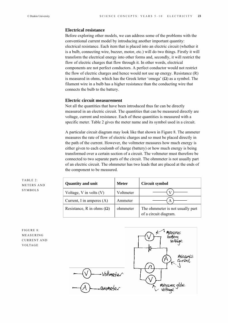
A particular circuit diagram may look like that shown in Figure 8. The ammeter measures the rate of flow of electric charges and so must be placed directly in the path of the current. However, the voltmeter measures how much energy is either given to each coulomb of charge (battery) or how much energy is being transformed over a certain section of a circuit. The voltmeter must therefore be connected to two separate parts of the circuit. The ohmmeter is not usually part of an electric circuit. The ohmmeter has two leads that are placed at the ends of the component to be measured.
Quantity and unit Meter Circuit symbol
Voltage, V in volts (V) Voltmeter V
Current, I in amperes (A) Ammeter A
Resistance, R in ohms (Ω) ohmmeter The ohmmeter is not usually part of a circuit diagram.
T A B L E 2 : M E T E R S A N D S Y M B O L S
F I G U R E 8 : M E A S U R I N G C U R R E NT A ND V O LTA G E

24 S C I E N C E C O N C E P T S : Y E A R S 5 – 1 0 E L E C T R I C I T Y © Deakin University
Conventional current model revisited With our understanding of electrical resistance, we can revisit our previous interpretations of circuits. The conducting path for the electric charges to flow can be imagined as a wide path for the wires and a narrow path for the bulb. The size of the current is determined by the restrictions in the path. If there is only a single conducting path, as in a series circuit, then the size of the current is determined by the resistances in the circuit.
This model can now successfully explain the following points: • The current in circuit 2 will be less than circuit 1 as there are two
restrictions to current in circuit 2, whereas there is only one restriction in circuit 1.
• The current in circuit 3 will be more than in circuit 1 as there is less restriction for charges to travel from the battery back to the battery.
• The circuit shown in Figure 9 produces a very large current in what is called a ‘short-circuit’. A short-circuit contains a conducting path of very low resistance (like a wire that is placed across the terminals of a battery). As there is a large current there is also a large amount of energy being transferred, usually as heat energy. Circuits that produce large currents make batteries go flat quickly.
• There is a very small current through an insulator, such as a piece of plastic, placed in the circuit. Placing a piece of plastic across the terminals of a battery will produce an extremely small current (if anything at all) and so very little energy is lost from the battery. Any charges flowing around a path still transform all the energy provided by the battery. In this situation there are very few charges and so the total energy transformed in the insulator will be small.
The model does not explain: • how the energy is gained and lost in the circuit • a number of points, such as why positive charges move; however the model
is still valuable to use for understanding what is happening in an electric circuit and predicting what may occur.
F I G U R E 9 : S H O RT- C IR C U I T

© Deakin University S C I E N C E C O N C E P T S : Y E A R S 5 – 1 0 E L E C T R I C I T Y 25
Role-play and delivery truck models Role-play is helpful for explaining electric circuits to students. For a circuit containing a battery, bulb, connecting wire and a switch, you can represent what is happening through students acting as energy carriers (i.e. as charges). The following representations are made: • The charges are represented by students. • The battery is represented by a student who holds a certain number of
tokens (these tokens represent energy). • Energy is represented by tokens, such as discs or pieces of paper. • The conducting wire is represented by a clearly laid out path that includes
the battery and bulb. • The bulb is represented by a student. When the student bulb receives a
token (energy) from the student charges, they need to expend some energy (like jumping up and down or flailing their arms).
The student charges walk around a continuous path. Along this path there is a person who acts as a battery who gives tokens, which represent energy, to the student charges as they move around the circuit. The student charges then offload their energy tokens to a person acting as the bulb. The bulb person may do some action, such as waving a flag, every time they collect a token. Using role-play, think how you could act out: • a switch • a parallel circuit • a series circuit • a large resistance • a short-circuit.
The role-play model does not explain some of the observations in the activity Electric bulb circuits, unless rules for the role-play are added. For example: • In a single circuit with one bulb and one battery, all the energy tokens given
to the student charges by the student battery must be given to the student bulb.
• In a series circuit that includes two bulbs, the student charges give equal numbers of energy tokens to each student bulb.
• In a parallel circuit that contains two student bulbs, equal numbers of students need to go along each branch of the circuit.
If such rules are not imposed on the role-play, the role-play model does not predict what is observed with the actual circuits. A model, after all, needs to match the observations with the real data.
Another model that children and adults may be able to relate to is the delivery truck model. In this model, trucks act as charges, roads act as conducting wires, parcels act as energy, a warehouse full of parcels acts as a battery and houses and shops act as bulbs or loads. With this model you may consider how different circuits operate. If the roads are all ‘one way’, this conveniently explains that current flows in only one direction. Trucks deliver parcels to each house on their route, which accounts for energy transmission in all bulbs in a

26 S C I E N C E C O N C E P T S : Y E A R S 5 – 1 0 E L E C T R I C I T Y © Deakin University
series circuit. Trucks have a specific route to follow, so in cases of representing parallel circuits there will be trucks that enter each possible route.
So far we have outlined and discussed the following models: • energy consumption model • conventional current model • role-play model • delivery truck model.
You will need: • a voltmeter • an ammeter • three bulbs • a battery • connecting wires • various metals • plastic • lead (from a pencil) • water • salt water.
Build the circuits in the figure Measuring electric circuits, and take voltage readings from the voltmeter and current readings from the ammeter. Evaluate the readings you obtain with your interpretation of the conventional current model.
1) Compare current and voltage readings
2) Compare current and voltage readings with those from circuits in 1.
A C T I V I T Y: M E A S U R I N G E L E C T R I C C I R C U I T S
F I G U R E 1 3 : M E A S U R I N G E L E C T R I C C I R C U I T S

© Deakin University S C I E N C E C O N C E P T S : Y E A R S 5 – 1 0 E L E C T R I C I T Y 27
3) Compare current and voltage readings with circuits in 1 and 2.
4) Place different material between the ends of the open leads and take current readings. Determine if the material is a conductor or insulator.
Test: • metals (different types) • plastic • lead from a pencil • water • salt water.
1) The voltage over the battery equals the voltage over the bulb. The current in the left-hand wire equals the current in the right-hand wire.
2) The current in these circuits is less than in circuit 1. The voltage over the battery equals the combined voltages over the bulbs.
3) The current in the first circuit is greater than that in circuit 1. The current in the left-hand wire equals the total of the two currents in the parallel branches. The voltage over the battery equals the voltage across each of the bulbs. The voltage across each bulb equals the voltage across the build in circuit 1.
4) The metals and lead in the pencil (carbon) are conductors. Salt water is more of a conductor than water. Plastic is an insulator.
Higher order models of electric circuits The conventional current model explains many phenomena related to electric circuits. However, if you are interested in the ways in which electric circuits work, this section relates to Kirchhoff’s laws, the water pipe model and the electrical field model, which will explain electric circuits further.
Kirchhoff’s laws Two very important laws can be applied to any electric circuit: the voltage loop law and the current node law. These two laws can be understood from thinking about the conventional current model.
Voltage loop law In any working electric circuit, there can be any number of conducting paths that form continuous loops. Loops may or may not contain a battery (in a parallel circuit there is one loop that does not contain a battery). Each loop is

28 S C I E N C E C O N C E P T S : Y E A R S 5 – 1 0 E L E C T R I C I T Y © Deakin University
assigned a direction. In each of these loops the total voltage gains equal the total voltage losses. A voltage gain or loss is determined by the assigned direction of the loop. For example, if the loop direction follows that of the current then a battery voltage is interpreted as a voltage gain and a bulb voltage will be interpreted as a voltage loss. However, if the loop direction is opposite to the current then the battery voltage is interpreted as a voltage loss and the bulb voltage is interpreted as a voltage gain. For example, in the circuit diagram in Figure 10, three loops have been labelled.
For Loop L1: V1 – V2 – V3 = 0
For Loop L2: V1 – V2 – V4 = 0
For Loop L3: V4 – V3 = 0
Current node law A node is a point in a circuit where a current enters and leaves. Depending on the node, there could be any number of currents that enter the point and any number that leave. This can occur in a parallel circuit as in Figure 10. The law simply states that the total current that enters a node equals the total current that leaves the node. For example, in Figure 10: I1 + I2 = I3
Water pipe model While the conventional current model is successful in many ways, it does not constitute the only model that can explain electrical effects. The water pipe model represents an idea that electric current is like water flowing in a pipe. In this model: • electric charges are represented by water particles • the conducting path is an enclosed pipe system where at one part of the
system water is raised a vertical distance and at other parts of the system water is allowed to fall
• the battery is represented by a pump that raises the water a vertical distance • the energy consumers (for example a bulb), or the loads, are represented by
vertical pipes of varying widths.
F I G U R E 1 0 : V O LTA G E L O O P L AW A N D C U R R E N T N O D E L AW
© Deakin University S C I E N C E C O N C E P T S : Y E A R S 5 – 1 0 E L E C T R I C I T Y 29
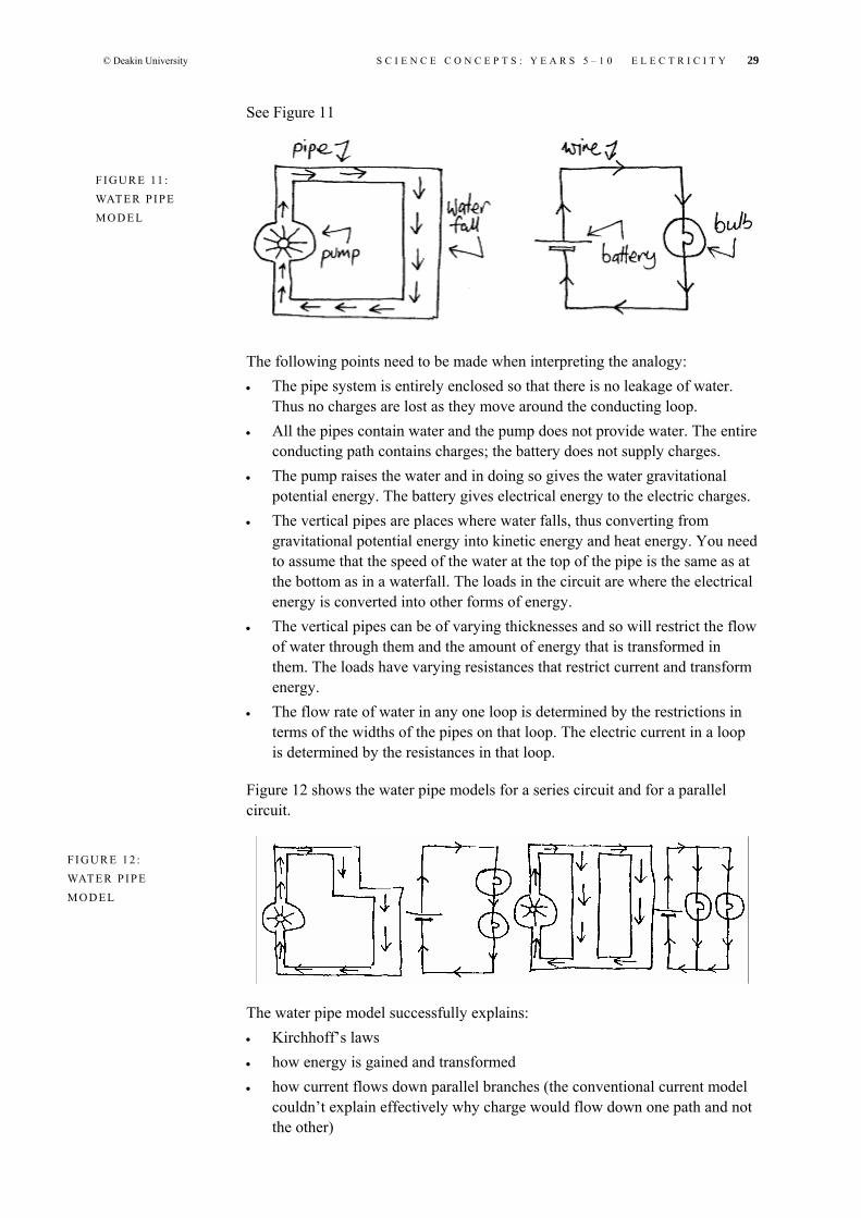
See Figure 11
The following points need to be made when interpreting the analogy: • The pipe system is entirely enclosed so that there is no leakage of water.
Thus no charges are lost as they move around the conducting loop. • All the pipes contain water and the pump does not provide water. The entire
conducting path contains charges; the battery does not supply charges. • The pump raises the water and in doing so gives the water gravitational
potential energy. The battery gives electrical energy to the electric charges. • The vertical pipes are places where water falls, thus converting from
gravitational potential energy into kinetic energy and heat energy. You need to assume that the speed of the water at the top of the pipe is the same as at the bottom as in a waterfall. The loads in the circuit are where the electrical energy is converted into other forms of energy.
• The vertical pipes can be of varying thicknesses and so will restrict the flow of water through them and the amount of energy that is transformed in them. The loads have varying resistances that restrict current and transform energy.
• The flow rate of water in any one loop is determined by the restrictions in terms of the widths of the pipes on that loop. The electric current in a loop is determined by the resistances in that loop.
Figure 12 shows the water pipe models for a series circuit and for a parallel circuit.
The water pipe model successfully explains: • Kirchhoff’s laws • how energy is gained and transformed • how current flows down parallel branches (the conventional current model
couldn’t explain effectively why charge would flow down one path and not the other)
F I G U R E 11 : WAT E R P I P E M O D E L
F I G U R E 1 2 : WAT E R P I P E M O D E L

30 S C I E N C E C O N C E P T S : Y E A R S 5 – 1 0 E L E C T R I C I T Y © Deakin University
• that the energy changes that occur in the loads of the circuit are almost instantaneous when the battery is connected in a complete circuit (the conventional current model predicts that there should be some delay where the loads are some distance from the positive terminal of the battery).
The water pipe model (this includes the conventional current model) does not explain: • that the electrons in the conducting path do not make continuous loops of a
circuit. The speed of the electrons is much slower than the speed at which the electrical effects occur (such as the time between turning on a light switch and the bulb lighting up).
• alternating current effects; many of our domestic electrical appliances such as lights, heaters, ovens, etcetera operate on what is termed ‘AC electricity’. This means that the current in a circuit not only varies between a maximum value and zero, it also reverses direction. This all occurs fifty times every second!
Electrical field model In pursuing other models that explain the two points above, we need to consider many more laws of physics, some of which are quite complex. No matter how complex the models become, you can never truly understand what actually goes on in an electric circuit. An interesting discussion on electric current can be found in an article by Beaty (1996) titled ‘Which way does the “electricity” really flow?’ (Be warned: this article will not enlighten you on what actually happens in an electric circuit.)
Yet another model uses the concept of an electrical field. An electrical field is like a gravitational field where bits of matter are affected by a gravitational field. Electric charges are affected by an electrical field. A piece of matter is forced to move in a gravitational field and an electric charge is forced to move in an electrical field. Let’s assume, for example, that you have just stepped off a diving board. If all of a sudden there was no gravitational field, you would be left stationary in the air. It does not matter how high you are up in the air because as soon as the gravitational field is turned on you will begin to fall. We can’t turn the gravitational field on and off, but we can turn an electrical field on or off. When the battery is connected to a conducting path, an electrical field is set up all along the conducting path almost instantaneously (at the speed of light). The electrons in this field, no matter where they are along the conducting path, will all be instantaneously affected. In this way energy is given to the electric charges almost instantaneously. Constantly changing the direction of the electrical field, as in AC electricity, still gives energy to the electrons.
© Deakin University S C I E N C E C O N C E P T S : Y E A R S 5 – 1 0 E L E C T R I C I T Y 31
Testing our understanding of electric circuits In the following activity it is important to ‘run the model’ so you can picture what is happening in the circuit before giving your predictions and explanations.
You will need: • bulbs • batteries • connecting wires.
For each of the situations outlined below predict what you think will happen and give an explanation.
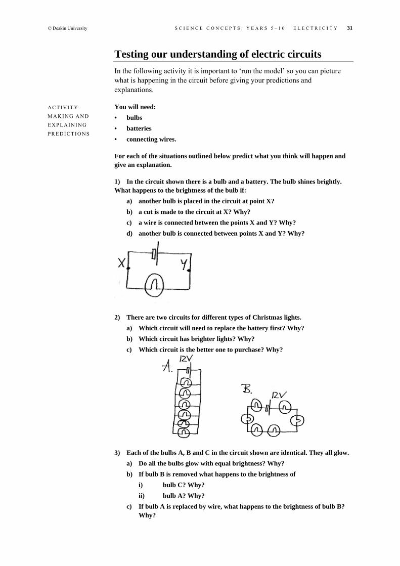
1) In the circuit shown there is a bulb and a battery. The bulb shines brightly. What happens to the brightness of the bulb if:
a) another bulb is placed in the circuit at point X? b) a cut is made to the circuit at X? Why? c) a wire is connected between the points X and Y? Why? d) another bulb is connected between points X and Y? Why?
2) There are two circuits for different types of Christmas lights. a) Which circuit will need to replace the battery first? Why? b) Which circuit has brighter lights? Why? c) Which circuit is the better one to purchase? Why?
3) Each of the bulbs A, B and C in the circuit shown are identical. They all glow. a) Do all the bulbs glow with equal brightness? Why? b) If bulb B is removed what happens to the brightness of
i) bulb C? Why? ii) bulb A? Why?
c) If bulb A is replaced by wire, what happens to the brightness of bulb B? Why?
A C T I V I T Y: M A K I N G A N D E X P L A I N I N G P R E D I C T I O NS

32 S C I E N C E C O N C E P T S : Y E A R S 5 – 1 0 E L E C T R I C I T Y © Deakin University
d) If bulb B is replaced by wire, what happens to the brightness of i) bulb A? Why?
ii) bulb C? Why?
Solutions: 1) a) The brightness in the bulb drops. Energy from the battery is being shared
between both bulbs now. b) No current flows in the open circuit, therefore the bulb will not be lit.
Currents only flow in complete circuits; that is, a conducting path from the positive terminal of the battery to the negative terminal of the same battery.
c) This is called a ‘short-circuit’. As the resistance in the wire is very small, most of the current will flow along the wire and not through the bulb. The bulb will not light up.
d) The brightness of the bulb remains the same. There is now twice as much current in the circuit; half passes through one bulb and the other half passes through the other.
2) a) Circuit A will need to be replaced first as there is a lot more current in this circuit. The greater the current, the greater the number of electric charges taking energy from the battery. b) Circuit A lights are brighter. The voltage across each of these lights is
12 V. This means that every 1 C of charge converts 12 J of energy at the bulb. In circuit B the voltage across each bulb is only 2 V.
c) Circuit A is better because if one of the bulb blows there will still be other bulbs that are lit. If a bulb blows in circuit A there will be an open circuit so no bulbs will be lit.
3) a) Bulb A becomes less bright. The total resistance of the circuit is more than before and so there is less current flowing through A. b) Bulb B becomes brighter. The total resistance of the circuit is less than
before and so more current flows. c) Bulb A becomes brighter as the total resistance of the circuit becomes less,
so more current flows. d) Bulb C does not light. It is short-circuited. Nearly all the current flows
through the wire because its resistance is very small.

© Deakin University S C I E N C E C O N C E P T S : Y E A R S 5 – 1 0 E L E C T R I C I T Y 33
You will need: • three globes • two batteries • three switches • connecting wire.
Draw electric circuits that will accomplish the following tasks: 1) All three globes are equally very bright. 2) All three globes are equally very dull. 3) One globe is very bright and two are dull. 4) All three globes are turned on and off by the one switch. 5) Each globe is controlled by its own switch. 6) One switch controls one globe, a second switch controls the other two globes,
and the third switch controls all three globes. 7) Two globes are on, but a switch turns one light off when it is pressed ‘on’.
The solution circuits are shown in the figure Solutions to globe problems.
A C T I V I T Y: I L L U M I N AT I N G G L O B E S
F I G U R E : S O L U T I O N S TO G L O B E P R O B L E M S

34 S C I E N C E C O N C E P T S : Y E A R S 5 – 1 0 E L E C T R I C I T Y © Deakin University
Household electricity Household electricity operates on alternating voltages and alternating currents, commonly termed ‘AC electricity’ (alternating current electricity). At a household power point the voltage varies from 330 V to –330 V (a negative voltage is equivalent to reversing the terminals of a battery). Figure 13 gives you an indication of how the voltage changes with time. Depending on the resistance of the household appliance, the current in the appliance will also vary from some maximum positive value to a minium negative value.
It is better to imagine household electricity like DC electricity (direct current electricity), where current is in one direction. We describe household voltage as 240 V with a frequency of 50 Hz. The 240 V is a comparison between the constantly changing alternating voltage (the voltage goes through a full cycle of change fifty times per second; 50 Hz) and DC electricity. The alternating voltage 330 V to –330 V gives the same heating effects, as if it were connected to an electric radiator, as a constant voltage of 240 V.
We should consider household AC electricity in terms of current in wires delivering energy to a load (appliance). You do not need to consider the changing direction of the current but just that when a switch is turned on there is current in the appliance which is transforming electrical energy into other forms of energy. The main components of electrical supply to households are as follows: • Two wires from the power pole in the street are connected to the house. It
looks like one wire but there are two. One of the wires is called the ‘active’ and the other is called the ‘neutral’. The active and neutral wires are connected to separate wires running along the power poles.
• The active wire is connected to the switchboard, which contains fuses (usually in older houses) or circuit-breakers (in modern houses). The fuses or circuit-breakers are rated by a specific current (for example, 10 A). If the current rating is exceeded, the fuse will melt, thus breaking the circuit and current will no longer be present. The fuse is made of wire that melts at a low temperature so that when a large enough current occurs the energy that is transformed is enough to melt the wire. The circuit-breaker is made up of an electromagnet and a switch. As its name suggests, it will break the circuit and, with a large enough current, the electromagnet will mechanically turn off a switch by a magnetic effect.
F I G U R E 1 3 : H O U S E H O L D E L E C T R I C I TY A S A LT E R N AT I N G V O LTA G E

© Deakin University S C I E N C E C O N C E P T S : Y E A R S 5 – 1 0 E L E C T R I C I T Y 35
The active wire is also connected to all the switches in the house. However, appliances can still operate if the switch is connected to the neutral wire instead. This can be very dangerous in certain circumstances. For example, when using a toaster, if you turn off the switch but keep the toaster connected, and the switch is on the neutral wire, you will be at risk of electrocution if you use a knife to extract your toast.
The active wire is finally connected to the power point. The top-left hole gives the active wire connection, although this may not always be true. The top right hole connects to the neutral wire and the bottom hole connects to the earth wire. See Figure 15.
The earth wire is connected to a main earthing conductor that extends under the ground. In many cases the earthing conductor is connected to the underground water pipe system or to a copper metal rod that extends some distance into the ground.
Most appliances have a three-point plug which matches up with the active, neutral and earth connections of the power point. The circuit diagram for a toaster or heater is shown in Figure 16. The active pin connects to a switch on the appliances which then connects to an element (a high-resistance conductor where electrical energy is transformed into heat energy) and finally there is a connection to the neutral pin. The earth pin is connected to the metallic housing of the heater or toaster and is not directly connected to the conducting path that contains the switch and the element but to the neutral wire at the switchboard.
F I G U R E 1 4 : H O U S E H O L D E L E C T R I C A L W I R I N G
F I G U R E 1 5 : P O W E R P O I N T

36 S C I E N C E C O N C E P T S : Y E A R S 5 – 1 0 E L E C T R I C I T Y © Deakin University
Operation of a household appliance We can now consider the operation of appliances when in use. For example, turning on the light switch achieves a complete circuit. This circuit is a continuous loop of conducting path that includes the generator in Gippsland or Snowy River and the bulb filament. The current direction is constantly changing in the light filament, delivering electrical energy that is transformed as heat and light energy. Most of the energy is being transformed in the bulb filament as it has the greatest resistance. For a 100 W bulb at 240 V voltage the current will be 0.42 A (calculated from P = VI) and the resistance is 576 Ω (calculated from V = IR).
The active and neutral wires have significance when considering the safety aspects of a household electricity circuit. While the earth wire on an appliance such as a toaster or heater is not normally connected to the path containing the active and neutral wires, there are earth connections all along the neutral wire from the point of contact at the house all the way to the generator. These earth connections can be interpreted as the earth being part of the neutral wire in that it makes a parallel branch to the neutral wire. In a normal operating circuit all the current is in the neutral wire as it is a far better conductor than the earth. The conducting path is shown by arrows in Figure 17.
If the active wire in a toaster or heater comes loose, then one of two things can happen. The first is that the circuit will be broken and no current will flow. The second is that the wire may touch the metal casing that is connected to the earth wire. In this circumstance a circuit will be complete as the conducting path is now from the active wire, through the toaster, through the earth wire and back
F I G U R E 1 6 : TO A S T E R C IR C U I T
F I G U R E 1 7 : C O M P L E T E TO A S T E R C IR C U I T

© Deakin University S C I E N C E C O N C E P T S : Y E A R S 5 – 1 0 E L E C T R I C I T Y 37
through the neutral wire at the switchboard to the generator. This complete circuit has a low resistance and so a large current occurs which in turn blows the fuse or activates the circuit-breaker. Fuses and circuit-breakers break the circuit quickly but, in circumstances where humans become part of the circuit, this may not be quick enough. Electronic circuit-breakers, called ‘residual current devices’ (RCDs) can be installed in houses to compare the current in the active wire with that in the neutral wire. If the circuit is functioning properly then the RCD is not activated. However, even if there is some current leakage through the earth wire, the RCD will activate immediately by breaking the circuit when it detects an imbalance in the currents in the active and neutral wires. The circuit diagram for this complete circuit is shown in Figure 18.
If a person touches an active wire, unless they are heavily insulated, say with rubber gloves and gumboots, then the person makes a conducting path to the earth. Current flows from the active wire through the person into the ground and back along the neutral wire to the generator. Generally the resistance of the person and ground is not small enough to produce enough current to blow a fuse or activate a circuit-breaker, but in most cases the current is large enough to electrocute the person. The circuit diagram for this complete circuit is shown in Figure 19.
Depending on the quality of the RCD the person will not be electrocuted as the switch is activated very quickly, but the RCD will not activate if a person completes the circuit by coming into contact with both the active and neutral wires. In addition, current still exists, even momentarily, in the body before an RCD activates which may have various effects on the person.
Birds quite often land on powerlines without being electrocuted. The reason is that the bird makes a parallel branch to the active wire. The resistance of the bird is very much greater than that of the wire section between its legs. This means that nearly all the current passes through the active wire and not through the bird. However, if the bird were to touch the branches of a tree or another bird on another wire then a complete series circuit would ensue with the bird being part of the circuit and a large current would pass through the bird.
F I G U R E 1 8 : A C T I V E W I R E C O N TA C T E ART H
F I G U R E 1 9 : A P E R S O N TO U C H E S A N A C T I V E W I R E

38 S C I E N C E C O N C E P T S : Y E A R S 5 – 1 0 E L E C T R I C I T Y © Deakin University
A number of websites give information about electrical hazards and the effects on the human body. Explore the following websites to answer the question, ‘What kills you? Current or voltage?’
Electricity safety world http://www.smud.org/safety/world/
Electrical safety http://www.pp.okstate.edu/ehs/MODULES/electric/
Electricity and magnetism Electricity is very closely linked to magnetism. If you move an electric charge, you create what is termed a ‘magnetic field’, which in turn can repel and attract magnets and attract some metals, as well as attract and repel other moving charges. If you move a magnet you can create an electrical field, which we know moves electric charges. These electromagnetic effects are responsible for the operation of a number of devices (e.g. electromagnets, electric generators, transformers, electric motors and residual current devices (RCDs), microphones and loudspeakers). In the topic ‘Light’ we learn that visible light itself can be understood as an electromagnetic effect—the same as microwave radiation (from ovens and mobile telephones), radio wave radiation (radio stations) and gamma radiation (from uranium). Without going into the actual operation of electromagnetic devices, we will briefly describe some of these devices in the following paragraphs.
Electromagnets An electromagnet is just a coil of wire, usually wound around an iron cylinder, that contains a current. In Figure 21 we can imagine a permanent magnet (remember it has a north and south pole) as producing a magnetic field around it that is represented by force lines. Another magnet (like that in a compass) or a piece of iron that comes into the magnetic field will be affected in some way such as being attracted or repelled by the magnet. A current inside a coil of wire will produce a very similar magnetic field. A magnetic field is produced in a single wire but, to magnify the effect, several loops of wire are used. To further enhance the magnetic field of the electromagnet, a piece of magnetic material such as iron is put up the centre of the coil.
F I G U R E 2 0 : B I R D O N A P O W E R L I N E
A C T I V I T Y: W H AT K I L L S Y O U? C U R R E N T O R V O LTA G E?

© Deakin University S C I E N C E C O N C E P T S : Y E A R S 5 – 1 0 E L E C T R I C I T Y 39
You will need: • insulated wire • an iron nail • a battery.
Wind the wire several times around the nail as shown in the figure An electromagnet. Connecting the wires to a battery produces the electromagnet. Explore different magnetic effects through increasing the number of turns of the wire.
Electric motor You may have a broken child’s toy or broken kitchen appliance that contains an electric motor that you can pull apart to get direct access to the motor. You will find that the motor contains coils of wire that have a conducting path to a battery. The coils of wire are usually surrounded by curved permanent magnets. In the operation of the motor, a current in the coils produces an electromagnet that interacts with the permanent magnet. When playing with permanent magnets you may have noticed that in some arrangements two magnets attract each other and for other arrangements the magnets repel each other. However, inside the motor, the coils of wire and permanent magnet are arranged in such a way that the coil will spin on a shaft. The shaft is connected to wheels, propellers, and so on.
Loudspeaker A loudspeaker is a device that contains a coil of wire that can move backwards and forwards inside a circular permanent magnet. The coil is attached to a speaker cone that vibrates to provide the source of the sound. Current in the coil
F I G U R E 2 1 : P E R M A N E N T A N D T E M P O R A RY M A G N E T S
A C T I V I T Y: M A K I N G A N D T E S T I N G A N E L E C T R O M A G N E T
F I G U R E : A N E L E C T R O M A G N E T

40 S C I E N C E C O N C E P T S : Y E A R S 5 – 1 0 E L E C T R I C I T Y © Deakin University
will produce a magnetic field that either attracts the permanent magnet or repels it. If the coil is first repelled it can be attracted to the magnet if the direction of the current in the coil is reversed. So, by having an alternating current in the coil, the speaker cone will vibrate.
Microphone The microphone operates in a reverse process to the loudspeaker. The microphone consists of a diaphragm that is attached to a coil located inside a permanent circular magnet. The coil and the diaphragm are able to move and so when sound is produced the diaphragm and coil will vibrate at the same frequencies as the sound. By moving the coil inside a magnetic field an electrical field is induced in the coil. (In the loudspeaker and motor the electrical field in the coil induced a magnetic field around it.) As there is an electrical field in the wire there will be a current, and as the coil is vibrating there will be an alternating current induced in the coil. This alternating current is very small and is too small to operate the loudspeaker so a current amplifier is placed between the microphone and the speaker. The electronics of the amplifier magnify the changes in the alternating current. The frequencies of the alternating current match the frequencies of the sound coming into the microphone and also match the frequencies of the vibrating speaker cone of the loudspeaker. However, in modern amplifiers the sound is not a direct match as changes are made to the alternating current, such as removing some frequencies and enhancing others. You will notice on your sound system at home that there may be a dial to reduce noise and other dials to enhance or reduce lower range, mid-range or upper range frequencies in the sound.
Generators The generators that produce household electricity basically consist of two sets of coils. One set of coils is an electromagnet (containing an iron centre) and the other coil is attached to the active and neutral wires that span the countryside. The electromagnet spins inside the other coils and in doing so induces a current inside the other coil. The rotating electromagnet constantly changes the direction of the magnetic field and so an alternating current is induced in the stationary coil. The electromagnet rotates at a frequency of 50 Hz, which is what we would expect as this is the frequency of the alternating voltage or current in households.
Residual current devices (RCDs) Residual current devices are composed of a coil, an amplifier and a switch. The coil of wire surrounds both the active and neutral wires. In normal operation, current direction in the active wire is equal in magnitude but opposite in direction to the current in the neutral wire. As described for the generator, the current in the active wire will induce a current in the coil in a specific direction. However, the current in the neutral wire will also induce a current in the coil but it will be in the opposite direction to the induced current from the active wire. The two effects cancel each other out, so if the circuit is operating normally

© Deakin University S C I E N C E C O N C E P T S : Y E A R S 5 – 1 0 E L E C T R I C I T Y 41
there will be no induced current in the coil. However, if there is some earth leakage the current in the active wire will be more than the current in the neutral wire, with the result of an overall induced current in the coil. This is usually very small and so an amplifier is employed to magnify the current that in turn will be large enough to activate a circuit-breaker.
Transformers Transformers are devices that can raise or lower the voltage. They consist of two coils of wire that coil around an iron loop. One coil provides points for an input voltage and the other coil provides points for an output voltage. There is no conducting path between the coils. The coils are insulated from the iron loop. As an alternating voltage is put into the input points and current flows through the input coil, an alternating current is induced in the output coil. Hence, a voltage will form at the output points. If the input coil has more windings than the output coil, there will be less voltage at the output. However, if the output coil has more windings than the input coil, there will be more voltage at the output. It seems that you can create or destroy energy, but this is not so. The amount of energy that enters the transformer must leave the transformer. So if the voltage is high (lots of energy per charge) the current will be small (just a few charges per second), and if the voltage is low (not much energy per charge) then the current will be high (lots of charges per second).
References Beaty, W 1996 ‘Which way does the “electricity” really flow?’,
<http://www.eskimo.com/~billb/amateur/elecdir.html>, viewed 10 March 2005.
Further resources Cooper, V, Pople, S, Ray, B, Seidel, P & Williams, M 1980, Science to sixteen
1, Oxford University Press. Cooper, V, Pople, S, Ray, B, Seidel, P & Williams, M 1980, Science to sixteen
2, Oxford University Press. DeJong, E, Armitage, F, Brown, M, Butler, P & Hayes, J 1990, Physics one,
Heinemann, Mebourne. DeJong, E, Armitage, F, Brown, M, Butler, P & Hayes, J 1990, Physics two,
Heinemann, Melbourne. Harding, J, Burrows, R, Del Balso, S & Forward, K 1996, Physics concepts &
applications VCE units 1 & 2, Macmillan, Melbourne. Harding, J, Burrows, R, Del Balso, S & Forward, K 1996, Physics concepts &
applications VCE units 3 & 4, Macmillan, Melbourne. Havis, S, Malcolm, C & Seddon, J 1992, Electricity, STAV Publishing,
Melbourne. Kelly, L, Tytler, R & Jane, B 2000, Ideas for teaching primary science, Deakin
University, Burwood, Vic.

42 S C I E N C E C O N C E P T S : Y E A R S 5 – 1 0 E L E C T R I C I T Y © Deakin University
Lofts, G, O’Keefe, D, Robertson, P, Pentland, P & Pearce, J 1997, Jacaranda physics 1, Jacaranda Wiley, Milton, Qld.
Lofts, G, O’Keefe, D, Robertson, P, Pentland, P & Pearce, J 1997, Jacaranda physics 2, Jacaranda Wiley, Milton, Qld.
Martin, SL & O’Connor, AK 1968, Basic physics I, Whitcombe & Tombs, Sydney.
Science Teacher’s Association of Victoria 1982, Physics in general science, STAV, Melbourne.
Stannard, P & Williamson, K 1999, Science world 7, 8, 9, 10, Macmillan, South Melbourne.
Stone, B 1986, Physics 3, Charles Letts, London. Storen, A & Martine, R 1987, Physics for senior students, Nelson, Melbourne. Tytler, R 2000, The science of toys and tricks activities book, Deakin
University, Geelong, Vic. Wilkinson, J 1990, World of physics book 1, Macmillan, Melbourne. Wilkinson, J 1990, World of physics book 2, Macmillan, Melbourne.