Embed Size (px)
Citation preview
Electricity and New Energy
Single-Phase Power Transformers
Student Manual 86377-00
Order no.: 86377-00 First Edition Revision level: 01/2015
By the staff of Festo Didactic
© Festo Didactic Ltée/Ltd, Quebec, Canada 2011 Internet: www.festo-didactic.com e-mail: [email protected]
Printed in Canada All rights reserved ISBN 978-2-89640-502-2 (Printed version) ISBN 978-2-89747-240-5 (CD-ROM) Legal Deposit – Bibliothèque et Archives nationales du Québec, 2011 Legal Deposit – Library and Archives Canada, 2011
The purchaser shall receive a single right of use which is non-exclusive, non-time-limited and limited geographically to use at the purchaser's site/location as follows.
The purchaser shall be entitled to use the work to train his/her staff at the purchaser's site/location and shall also be entitled to use parts of the copyright material as the basis for the production of his/her own training documentation for the training of his/her staff at the purchaser's site/location with acknowledgement of source and to make copies for this purpose. In the case of schools/technical colleges, training centers, and universities, the right of use shall also include use by school and college students and trainees at the purchaser's site/location for teaching purposes.
The right of use shall in all cases exclude the right to publish the copyright material or to make this available for use on intranet, Internet and LMS platforms and databases such as Moodle, which allow access by a wide variety of users, including those outside of the purchaser's site/location.
Entitlement to other rights relating to reproductions, copies, adaptations, translations, microfilming and transfer to and storage and processing in electronic systems, no matter whether in whole or in part, shall require the prior consent of Festo Didactic GmbH & Co. KG.
Information in this document is subject to change without notice and does not represent a commitment on the part of Festo Didactic. The Festo materials described in this document are furnished under a license agreement or a nondisclosure agreement.
Festo Didactic recognizes product names as trademarks or registered trademarks of their respective holders.
All other trademarks are the property of their respective owners. Other trademarks and trade names may be used in this document to refer to either the entity claiming the marks and names or their products. Festo Didactic disclaims any proprietary interest in trademarks and trade names other than its own.

© Festo Didactic 86377-00 III
Safety and Common Symbols
Caution, risk of danger
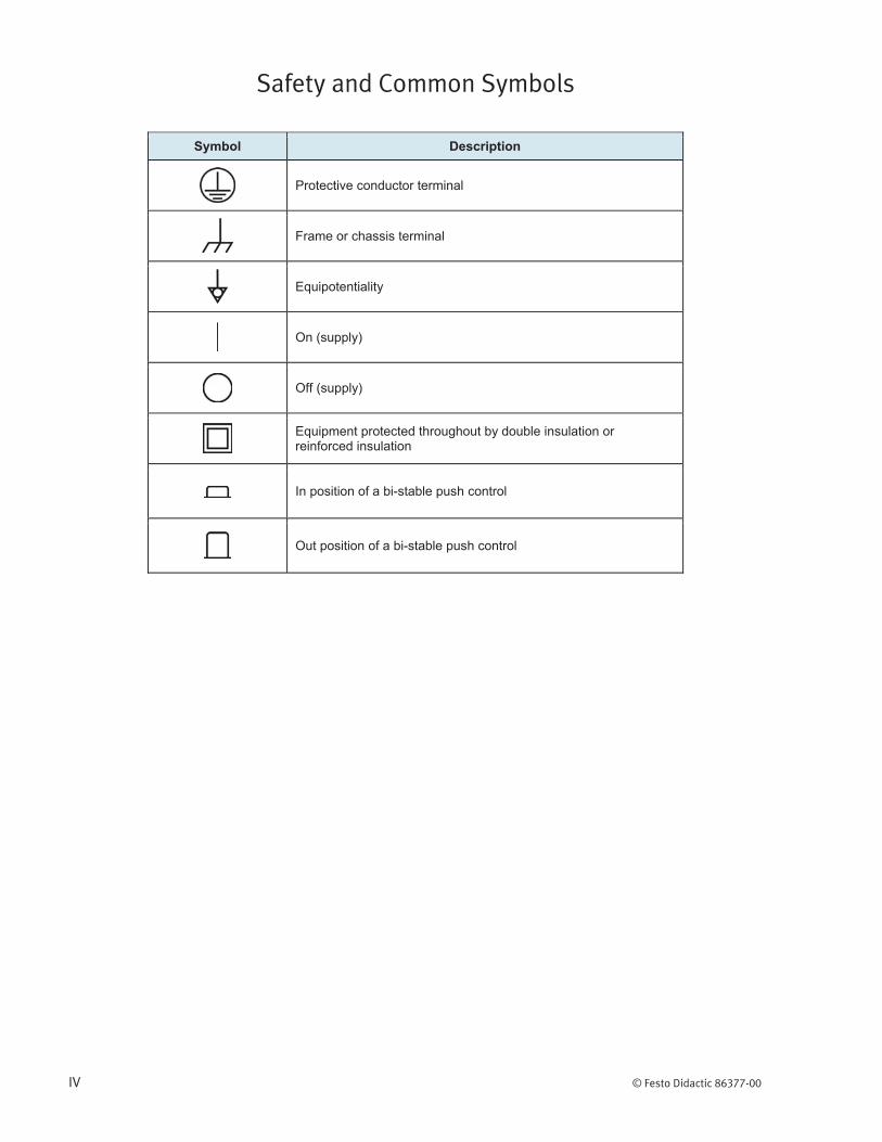
Safety and Common Symbols
IV © Festo Didactic 86377-00
© Festo Didactic 86377-00 V
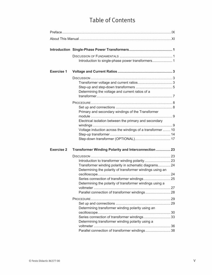
Table of Contents
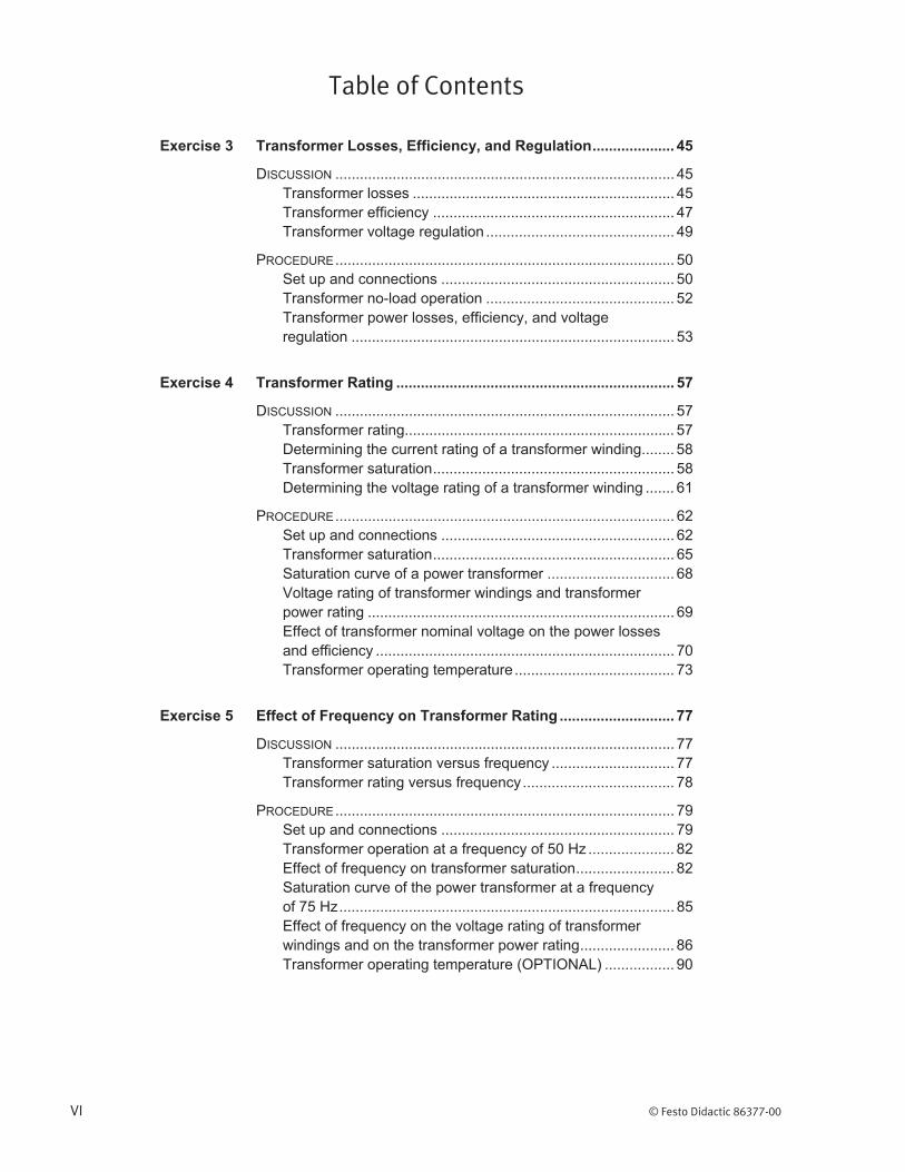
Table of Contents
VI © Festo Didactic 86377-00
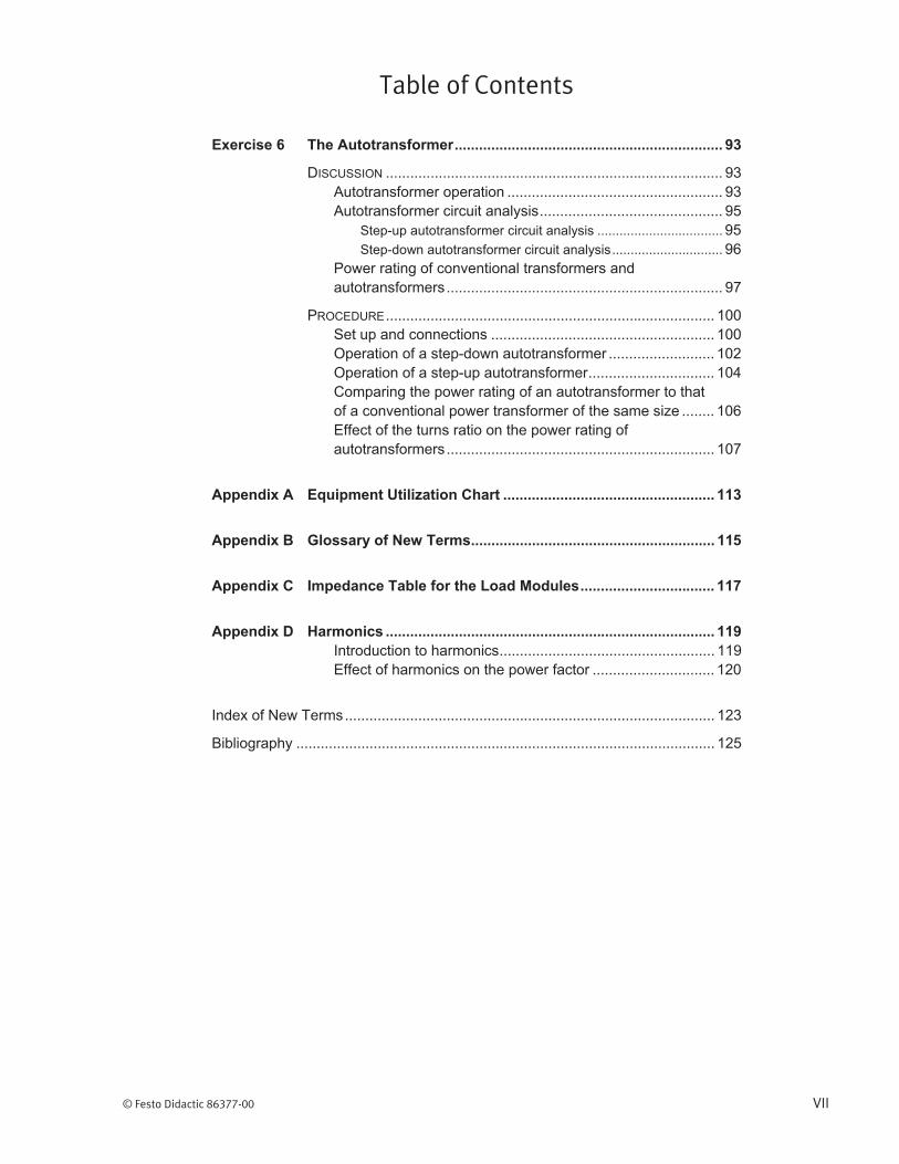
Table of Contents
© Festo Didactic 86377-00 VII


© Festo Didactic 86377-00 IX
Preface

Preface
X © Festo Didactic 86377-00

© Festo Didactic 86377-00 XI
About This Manual

About This Manual
XII © Festo Didactic 86377-00
Safety considerations
Prerequisite
DC Power Circuits Single-Phase AC Power Circuits
Systems of units

© Festo Didactic 86377-00 1
Introduction to single-phase power transformers
Single-Phase Power Transformers
Introduction
MANUAL OBJECTIVE
DISCUSSION OUTLINE
DISCUSSION OF FUNDAMENTALS

Introduction – Single-Phase Power Transformers Discussion of Fundamentals
2 © Festo Didactic 86377-00
© Festo Didactic 86377-00 3
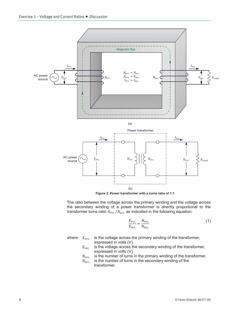
Transformer voltage and current ratios
Voltage and Current Ratios
Exercise 1
EXERCISE OBJECTIVE
DISCUSSION OUTLINE
DISCUSSION
Exercise 1 – Voltage and Current Ratios Discussion
4 © Festo Didactic 86377-00

Exercise 1 – Voltage and Current Ratios Discussion
© Festo Didactic 86377-00 5
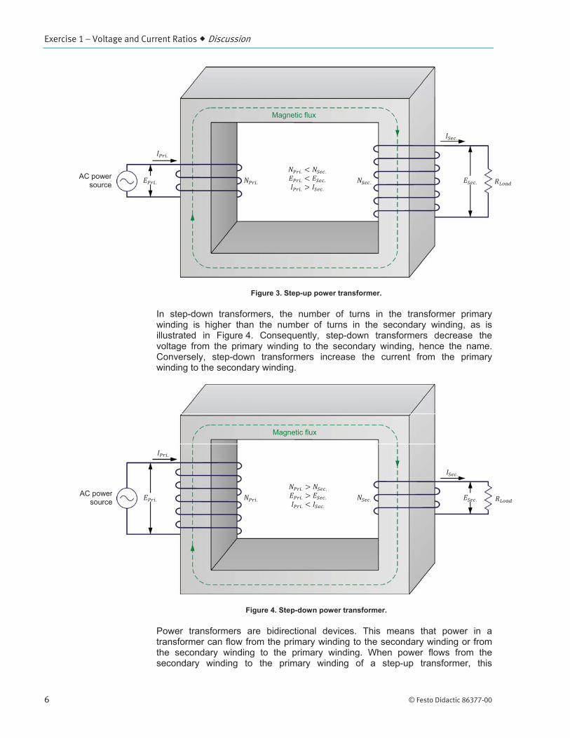
Step-up and step-down transformers
Exercise 1 – Voltage and Current Ratios Discussion
6 © Festo Didactic 86377-00
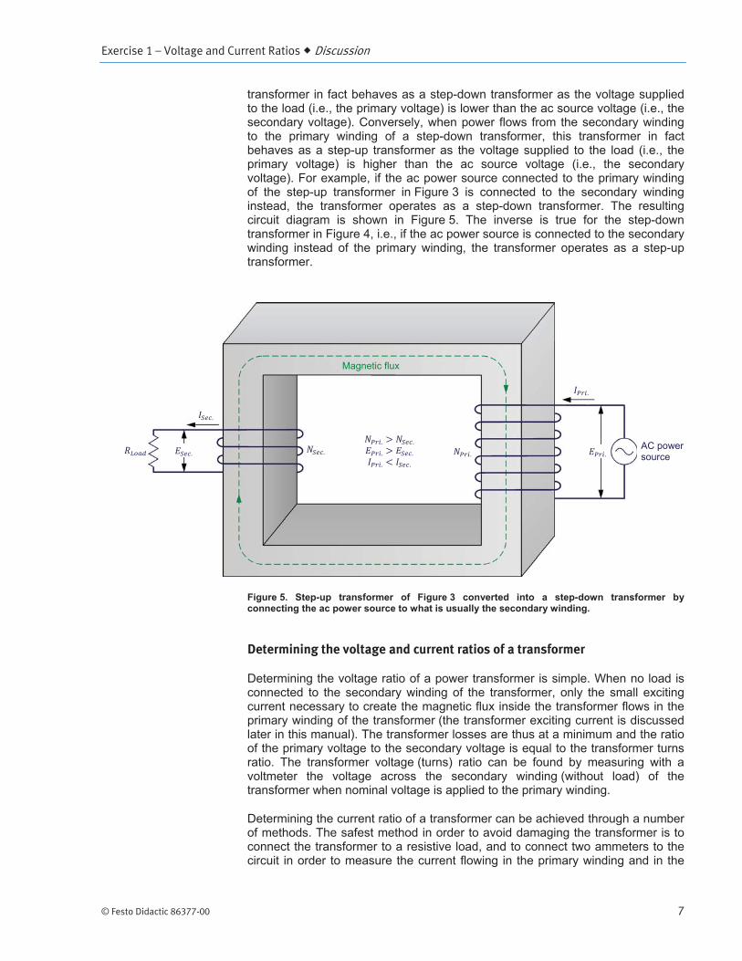
Exercise 1 – Voltage and Current Ratios Discussion
© Festo Didactic 86377-00 7
Determining the voltage and current ratios of a transformer
Exercise 1 – Voltage and Current Ratios Procedure Outline
8 © Festo Didactic 86377-00
Set up and connections
In this section, you will set up the equipment to study the operation of a power transformer.
Power Input
Power Input
Operating Mode Power Supply
PROCEDURE OUTLINE
PROCEDURE

Exercise 1 – Voltage and Current Ratios Procedure
© Festo Didactic 86377-00 9
Computer-Based Instrumentation
OK
Primary and secondary windings of the Transformer module
In this section, you will observe the transformer module and notice the ratings of the transformer windings.
Electrical isolation between the primary and secondary windings
In this section, you will use an ohmmeter to verify that a power transformer provides isolation between its primary and secondary windings.
Exercise 1 – Voltage and Current Ratios Procedure
10 © Festo Didactic 86377-00
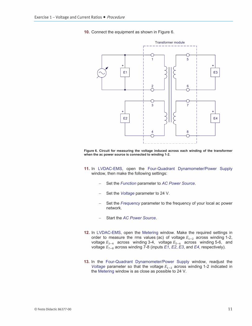
Voltage induction across the windings of a transformer
In this section, you will calculate the voltages induced across the various windings of the Transformer module when a voltage of 24 V is applied to winding 1-2. You will set up the equipment to measure the voltage across each winding of the Transformer module. You will apply a voltage of 24 V to winding 1-2, and measure the voltages induced across each other windings. You will compare the measured voltages with the calculated voltages. You will then calculate the voltages induced across the various windings of the Transformer module when a voltage of 100 V is applied to winding 5-6. You will apply a voltage of 100 V to winding 5-6, and measure the voltages induced across each other windings. Finally, you will compare the measured voltages with the calculated voltages.
Exercise 1 – Voltage and Current Ratios Procedure
© Festo Didactic 86377-00 11
Function AC Power Source
Voltage
Frequency
AC Power Source
E1 E2 E3 E4
Voltage
Exercise 1 – Voltage and Current Ratios Procedure
12 © Festo Didactic 86377-00
AC Power Source
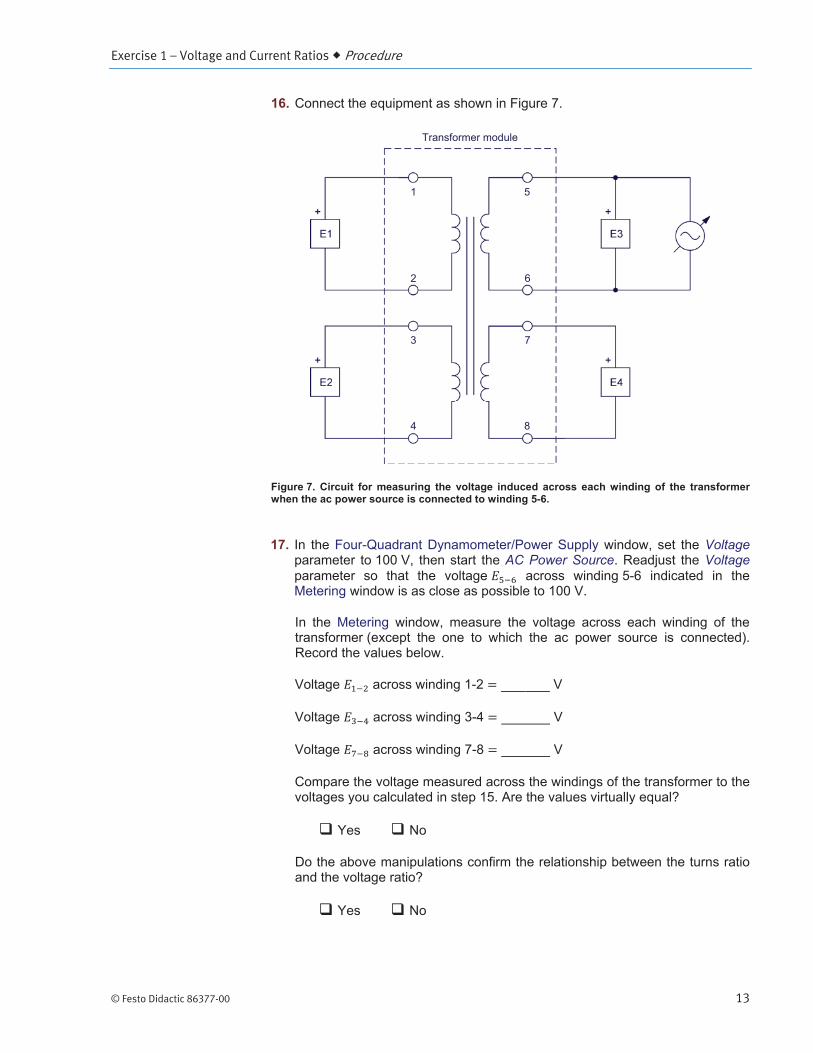
Exercise 1 – Voltage and Current Ratios Procedure
© Festo Didactic 86377-00 13
VoltageAC Power Source Voltage
Exercise 1 – Voltage and Current Ratios Procedure
14 © Festo Didactic 86377-00
AC Power Source
Step-up transformer
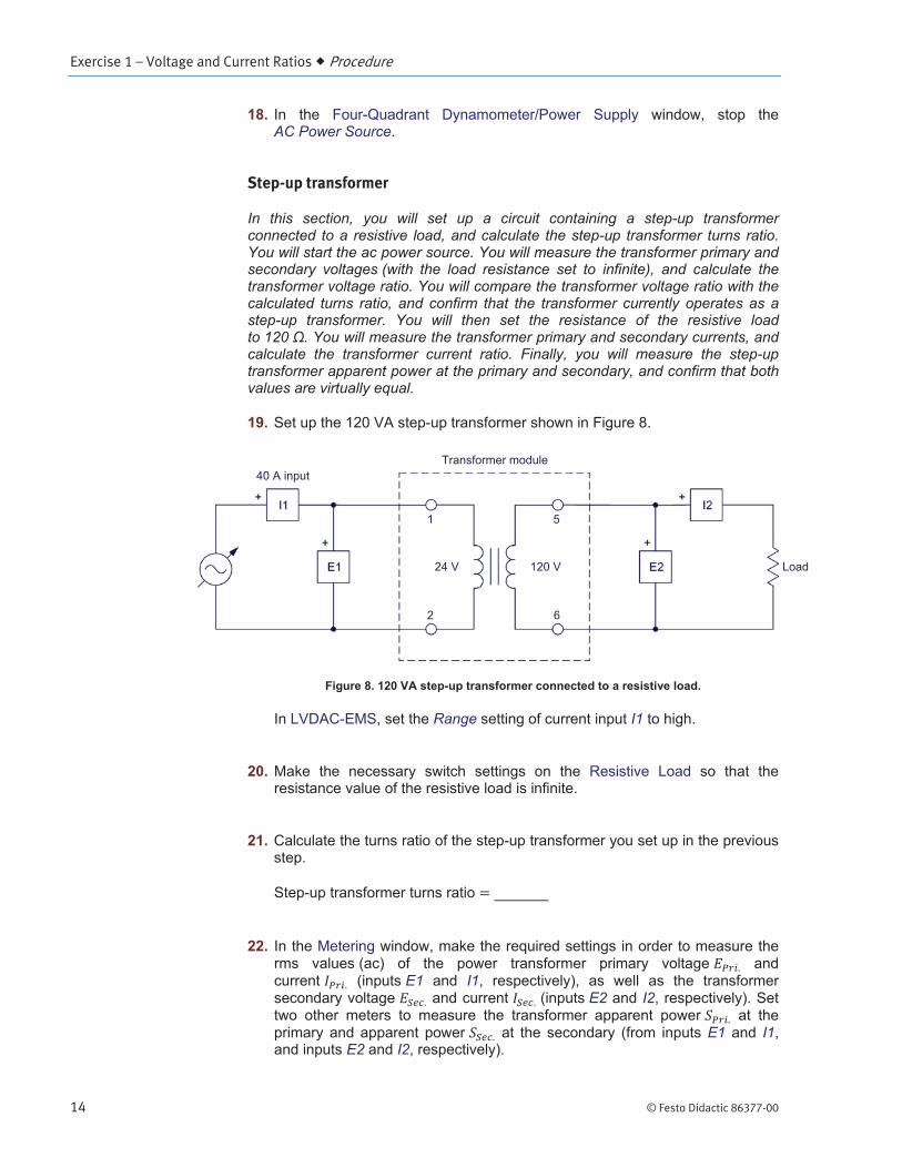
In this section, you will set up a circuit containing a step-up transformer connected to a resistive load, and calculate the step-up transformer turns ratio. You will start the ac power source. You will measure the transformer primary and secondary voltages (with the load resistance set to infinite), and calculate the transformer voltage ratio. You will compare the transformer voltage ratio with the calculated turns ratio, and confirm that the transformer currently operates as a step-up transformer. You will then set the resistance of the resistive load to 120 . You will measure the transformer primary and secondary currents, and calculate the transformer current ratio. Finally, you will measure the step-up transformer apparent power at the primary and secondary, and confirm that both values are virtually equal.
Range I1
E1 I1E2 I2
E1 I1E2 I2
Exercise 1 – Voltage and Current Ratios Procedure
© Festo Didactic 86377-00 15
VoltageAC Power Source Voltage
DC Offset Correction
a Adjusting the parameter of the ac power source ensures that virtually no dc current is supplied to the power transformer. This adjustment is required because dc current negatively affects the operation of power transformers.
Voltage
Exercise 1 – Voltage and Current Ratios Procedure
16 © Festo Didactic 86377-00
AC Power Source

Exercise 1 – Voltage and Current Ratios Procedure
© Festo Didactic 86377-00 17
Step-down transformer (OPTIONAL)
a This section is optional as it requires the use of the load resistors available in the Wind Turbine Generator/Controller module. These low-resistance load resistors are necessary to ensure that the current flowing in the primary winding of the step-down transformer is significant (in relation to the transformer nominal current).
In this section, you will set up a circuit containing a step-down transformer connected to a resistive load, and calculate the step-down transformer turns ratio. You will start the ac power source. You will measure the transformer primary and secondary voltages (with the load resistance set to infinite), and calculate the transformer voltage ratio. You will compare the transformer voltage ratio with the calculated turns ratio, and confirm that the transformer currently operates as a step-down transformer. You will then set the resistance of the resistive load to 5 . You will measure the transformer primary and secondary currents, and calculate the transformer current ratio. Finally, you will measure the step-down transformer apparent power values at the primary and secondary, and confirm that both values are virtually equal.
Range I1Range I2
Exercise 1 – Voltage and Current Ratios Procedure
18 © Festo Didactic 86377-00
VoltageAC Power Source Voltage
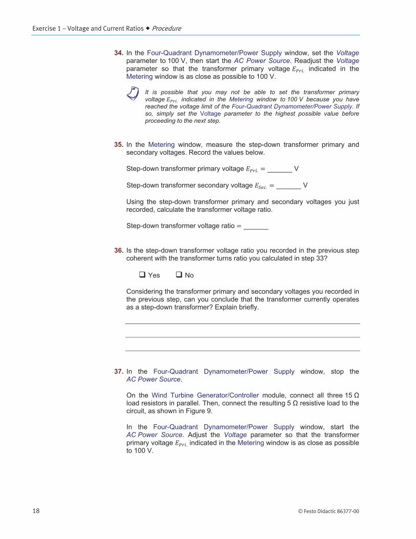
a It is possible that you may not be able to set the transformer primary voltage indicated in the Metering window to 100 V because you have reached the voltage limit of the Four-Quadrant Dynamometer/Power Supply. If so, simply set the parameter to the highest possible value before proceeding to the next step.
AC Power Source
AC Power Source Voltage
Exercise 1 – Voltage and Current Ratios Procedure
© Festo Didactic 86377-00 19
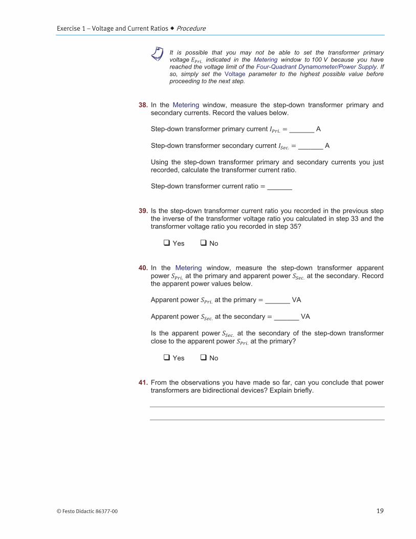
a It is possible that you may not be able to set the transformer primary voltage indicated in the Metering window to 100 V because you have reached the voltage limit of the Four-Quadrant Dynamometer/Power Supply. If so, simply set the parameter to the highest possible value before proceeding to the next step.
Exercise 1 – Voltage and Current Ratios Conclusion
20 © Festo Didactic 86377-00
AC Power Source
CONCLUSION
REVIEW QUESTIONS
Exercise 1 – Voltage and Current Ratios Review Questions
© Festo Didactic 86377-00 21

© Festo Didactic 86377-00 23
Introduction to transformer winding polarity
Transformer Winding Polarity and Interconnection
Exercise 2
EXERCISE OBJECTIVE
DISCUSSION OUTLINE
DISCUSSION

Exercise 2 – Transformer Winding Polarity and Interconnection Discussion
24 © Festo Didactic 86377-00
Transformer winding polarity in schematic diagrams
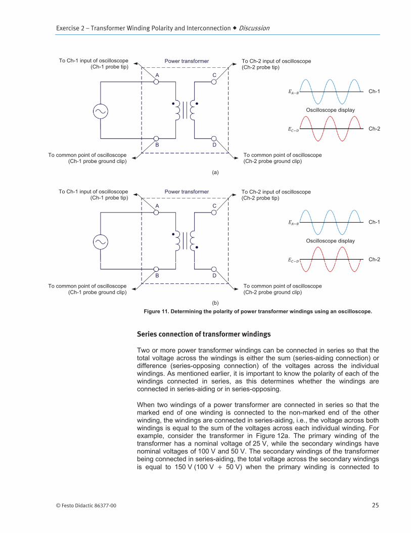
Determining the polarity of transformer windings using an oscilloscope
Exercise 2 – Transformer Winding Polarity and Interconnection Discussion
© Festo Didactic 86377-00 25
Series connection of transformer windings
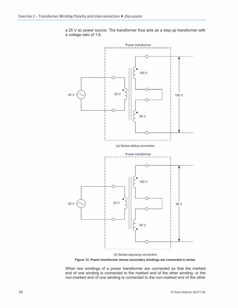
Exercise 2 – Transformer Winding Polarity and Interconnection Discussion
26 © Festo Didactic 86377-00
Exercise 2 – Transformer Winding Polarity and Interconnection Discussion
© Festo Didactic 86377-00 27
Determining the polarity of transformer windings using a voltmeter

Exercise 2 – Transformer Winding Polarity and Interconnection Discussion
28 © Festo Didactic 86377-00
Parallel connection of transformer windings

Exercise 2 – Transformer Winding Polarity and Interconnection Procedure Outline
© Festo Didactic 86377-00 29
Set up and connections
In this section, you will set up the equipment to study the operation of a power transformer. You will observe the polarity markings on the front panel of the transformer module and note which terminals have the same polarity as terminal 1.
PROCEDURE OUTLINE
PROCEDURE

Exercise 2 – Transformer Winding Polarity and Interconnection Procedure
30 © Festo Didactic 86377-00
Power Input
Power Input
Operating Mode Power Supply
Computer-Based Instrumentation
OK
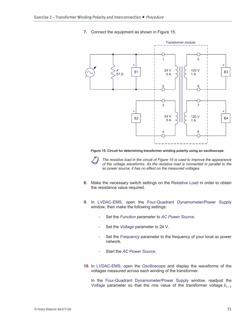
Determining transformer winding polarity using an oscilloscope
In this section, you will connect a circuit containing a power transformer and set up the equipment to determine the transformer winding polarity using the oscilloscope. You will start the ac power source. You will observe the waveforms of the voltage measured across each transformer winding, and determine the polarity of each transformer terminal. You will then observe in the Phasor Analyzer the phasors of the voltage measured across each transformer winding, and confirm the results you obtained using the Oscilloscope. You will reverse the connections at a voltage input of the Data Acquisition and Control Interface, and observe what happens to the corresponding voltage waveform on the Oscilloscope. You will determine if this inversion has any effect on the winding polarity that is found.
Exercise 2 – Transformer Winding Polarity and Interconnection Procedure
© Festo Didactic 86377-00 31
a The resistive load in the circuit of Figure 15 is used to improve the appearance of the voltage waveforms. As the resistive load is connected in parallel to the ac power source, it has no effect on the measured voltages.
Function AC Power Source
Voltage
Frequency
AC Power Source
Voltage

Exercise 2 – Transformer Winding Polarity and Interconnection Procedure
32 © Festo Didactic 86377-00
AC Power Source
E3
AC Power Source
E3
Exercise 2 – Transformer Winding Polarity and Interconnection Procedure
© Festo Didactic 86377-00 33
AC Power Source
Series connection of transformer windings
In this section, you will calculate the voltages induced across the series-connected windings of three different transformer setups. You will then set up each series connection of windings successively, and measure the voltage across each one. You will compare the measured voltages across the series windings with the calculated voltages.

Exercise 2 – Transformer Winding Polarity and Interconnection Procedure
34 © Festo Didactic 86377-00
Exercise 2 – Transformer Winding Polarity and Interconnection Procedure
© Festo Didactic 86377-00 35
a In all the transformer connections of Figure 16, the capacity of the transformer is limited to 120 VA, because all power is transferred through primary winding 1-2, which is rated 24 V and 5 A.
E1E2
AC Power Source Voltage
AC Power Source

Exercise 2 – Transformer Winding Polarity and Interconnection Procedure
36 © Festo Didactic 86377-00
Determining transformer winding polarity using a voltmeter
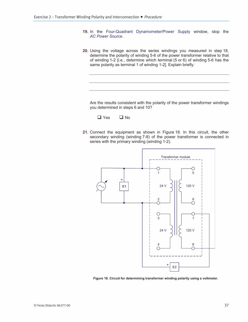
In this section, you will connect a circuit containing a transformer with series-connected windings (windings 1-2 and 5-6). You will start the ac power source and measure the voltages across the series-connected windings. Using the measured voltage, you will determine the polarity of the transformer windings. You will compare the winding polarities you obtained using this method with the winding polarities you determined previously in this exercise. You will then connect another circuit containing a transformer with series-connected windings (windings 1-2 and 7-8), and repeat the above manipulations.
AC Power Source Voltage
Exercise 2 – Transformer Winding Polarity and Interconnection Procedure
© Festo Didactic 86377-00 37
AC Power Source
Exercise 2 – Transformer Winding Polarity and Interconnection Procedure
38 © Festo Didactic 86377-00
AC Power Source Voltage
AC Power Source
Parallel connection of transformer windings
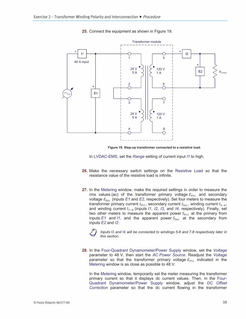
In this section, you will set up a step-up transformer connected to a resistive load. You will start the ac power source and confirm that the transformer secondary voltage is equal to 120 V. You will set the resistance of the resistive load to 120 . The secondary current should thus be virtually equal to the nominal current (1 A). You will measure the transformer primary voltage, current, and apparent power, as well as the secondary voltage, current, and apparent power. You will then modify the circuit so that the secondary windings of the transformer are connected in parallel. You will confirm that the secondary voltage, current, and apparent power have not changed, and that the two windings of the secondary are now sharing the secondary current equally. You will set the resistance of the resistive load to 57 . The current flowing in each winding of the secondary should thus be virtually equal to the nominal current (1 A). You will measure the transformer primary voltage, current and apparent power, as well as the secondary voltage, current, and apparent power, and analyze the results.
Exercise 2 – Transformer Winding Polarity and Interconnection Procedure
© Festo Didactic 86377-00 39
Range I1
E1 E2
I1 I2 I3 I4
E1 I1E2 I2
a Inputs and will be connected to windings 5-6 and 7-8 respectively later in this section.
VoltageAC Power Source Voltage
DC Offset Correction

Exercise 2 – Transformer Winding Polarity and Interconnection Procedure
40 © Festo Didactic 86377-00
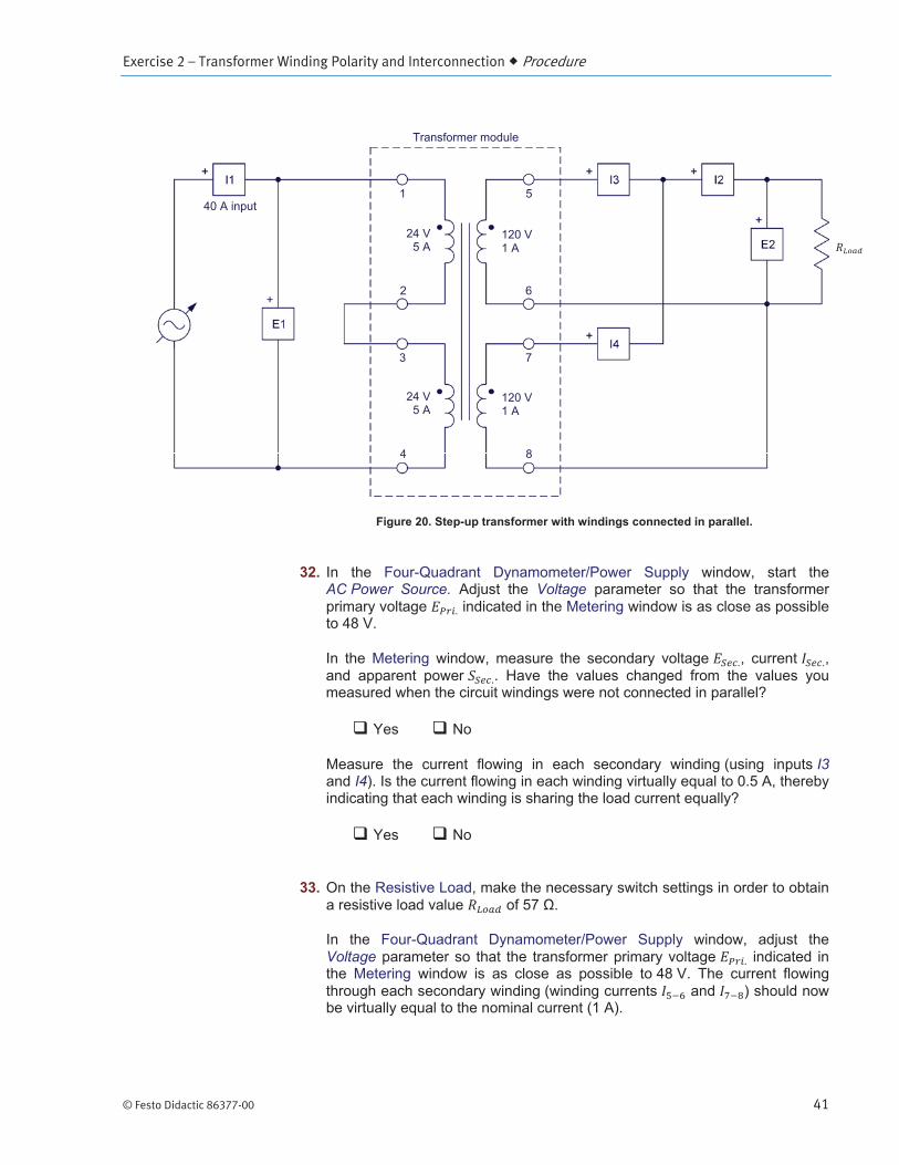
Voltage
AC Power Source
Exercise 2 – Transformer Winding Polarity and Interconnection Procedure
© Festo Didactic 86377-00 41
AC Power Source. Voltage
I3I4
Voltage

Exercise 2 – Transformer Winding Polarity and Interconnection Procedure
42 © Festo Didactic 86377-00
AC Power Source

Exercise 2 – Transformer Winding Polarity and Interconnection Conclusion
© Festo Didactic 86377-00 43
CONCLUSION
REVIEW QUESTIONS
Exercise 2 – Transformer Winding Polarity and Interconnection Review Questions
44 © Festo Didactic 86377-00
© Festo Didactic 86377-00 45
Transformer losses
Transformer Losses, Efficiency, and Regulation
Exercise 3
EXERCISE OBJECTIVE
DISCUSSION OUTLINE
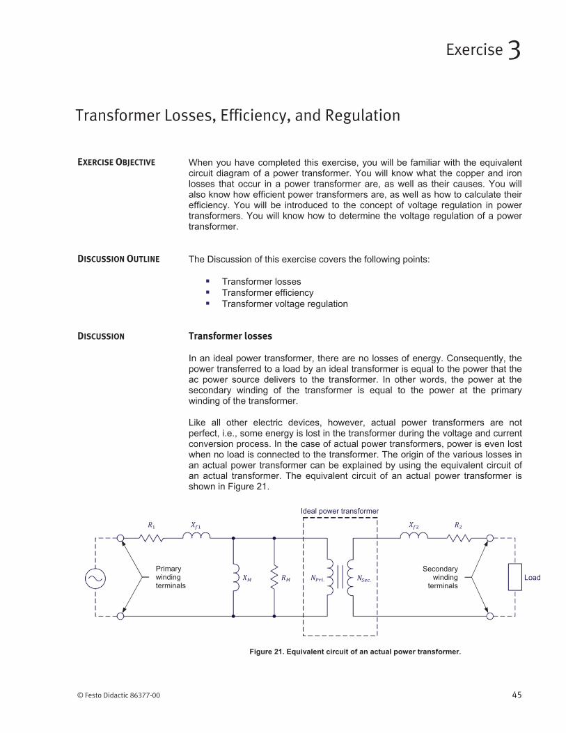
DISCUSSION
Exercise 3 – Transformer Losses, Efficiency, and Regulation Discussion
46 © Festo Didactic 86377-00
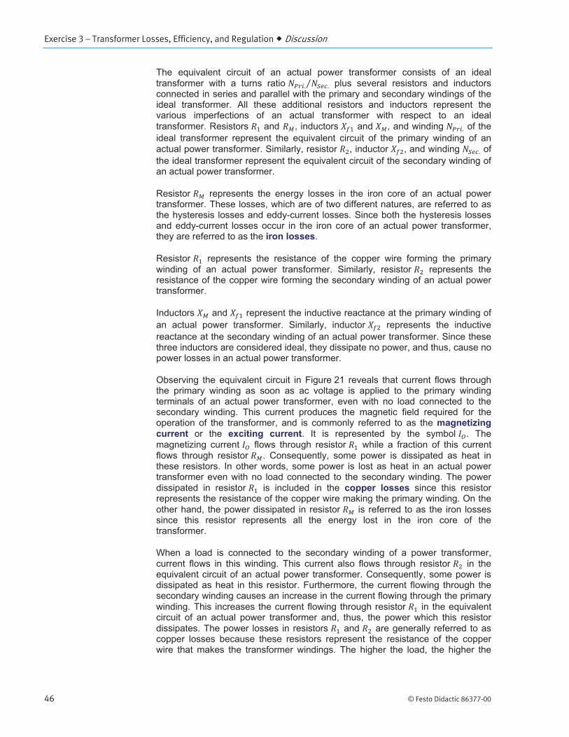
Exercise 3 – Transformer Losses, Efficiency, and Regulation Discussion
© Festo Didactic 86377-00 47
Transformer efficiency
Exercise 3 – Transformer Losses, Efficiency, and Regulation Discussion
48 © Festo Didactic 86377-00

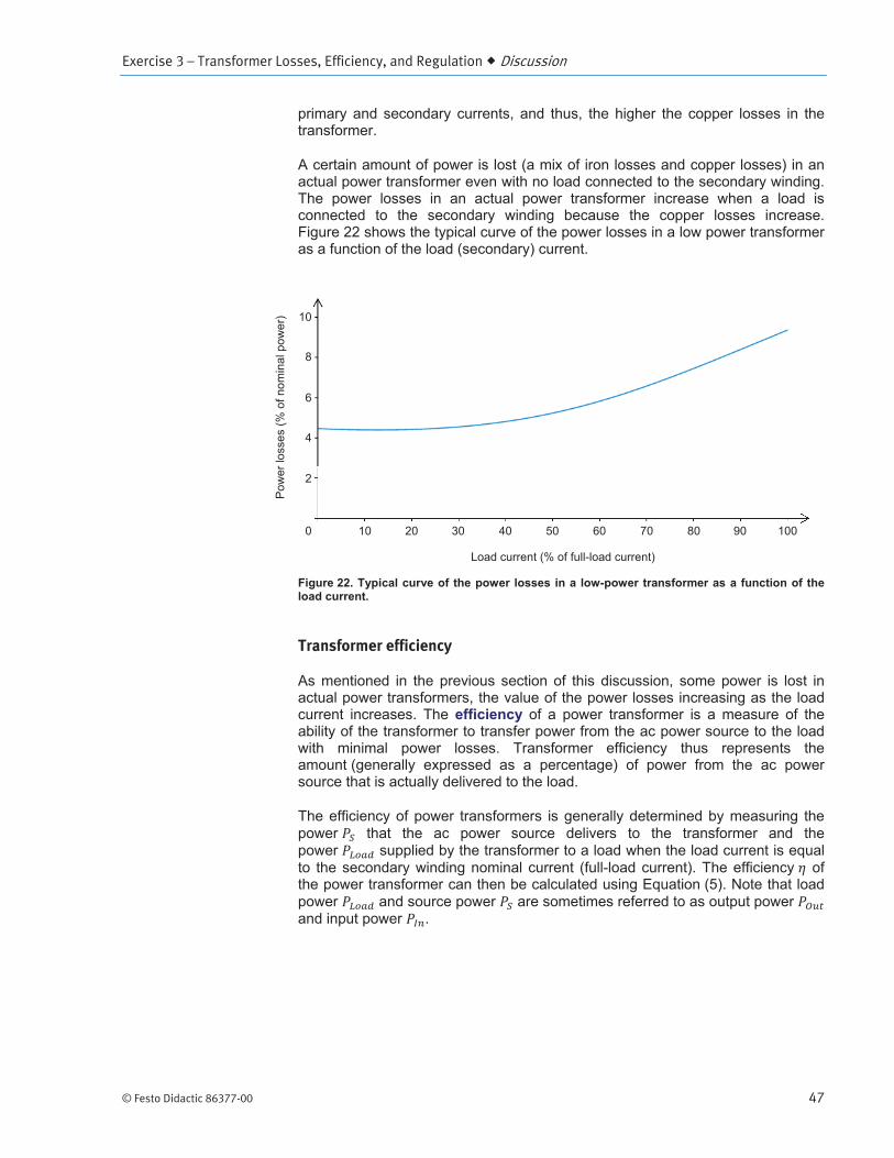
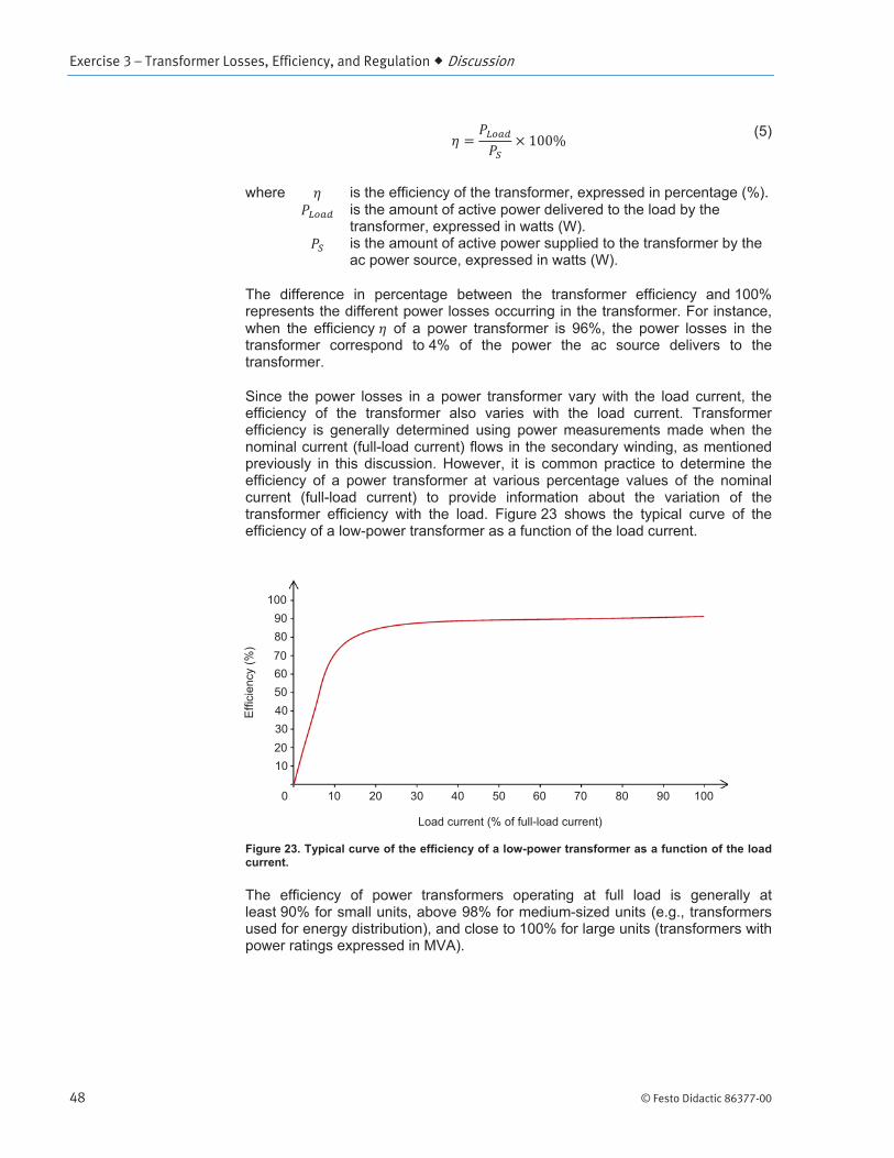
Exercise 3 – Transformer Losses, Efficiency, and Regulation Discussion
© Festo Didactic 86377-00 49
Transformer voltage regulation
Exercise 3 – Transformer Losses, Efficiency, and Regulation Procedure Outline
50 © Festo Didactic 86377-00
Set up and connections
In this section, you will set up a circuit containing a power transformer connected to a resistive load. You will then set the measuring equipment required to study the transformer power losses, efficiency, and voltage regulation.
Power Input
Power Input
PROCEDURE OUTLINE
PROCEDURE
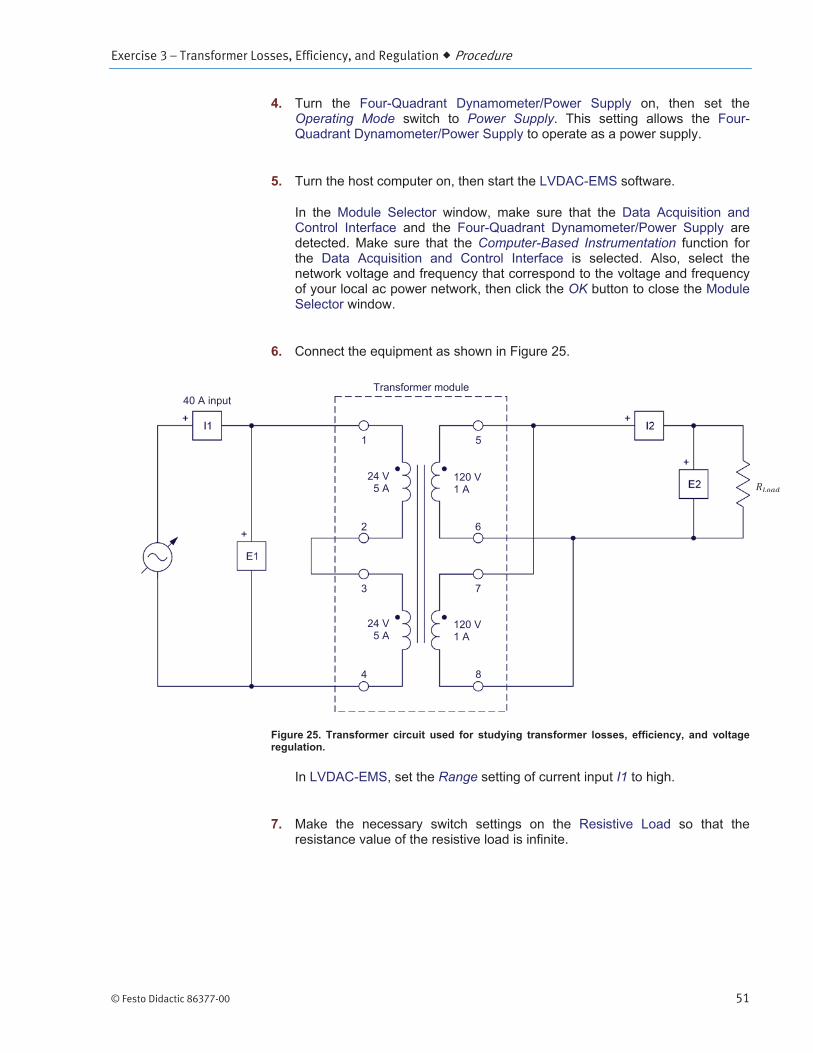
Exercise 3 – Transformer Losses, Efficiency, and Regulation Procedure
© Festo Didactic 86377-00 51
Operating Mode Power Supply
Computer-Based Instrumentation
OK
Range I1
Exercise 3 – Transformer Losses, Efficiency, and Regulation Procedure
52 © Festo Didactic 86377-00
Function AC Power Source
Voltage
Frequency
a Most power transformers are generally designed to operate at frequencies of 50 Hz and 60 Hz. Because transformer design requirements are more stringent at 50 Hz, most transformer designs are based on operation at 50 Hz, hence the setting of the ac power source frequency to 50 Hz.
E1 I1E2 I2
E1 I1E2 I2
Transformer no-load operation
In this section, you will start the ac power source. You will measure the current and active power at the transformer primary during no-load operation, and explain why they are not equal to zero.
AC Power Source Voltage
DC Offset Correction
Exercise 3 – Transformer Losses, Efficiency, and Regulation Procedure
© Festo Didactic 86377-00 53
Transformer power losses, efficiency, and voltage regulation
In this section, you will decrease the resistance of the load connected to the secondary so that the secondary current increases to 2.0 A (nominal full-load current) by steps of about 0.2 A. For each step, you will record in the Data Table the transformer primary voltage, current, and active power, as well as the secondary voltage, current, and active power. You will export the data to a spreadsheet, and calculate the transformer power losses and efficiency using the recorded transformer parameters. You will plot a graph of the transformer power losses as a function of the secondary current, and analyze the results. You will also plot a graph of the transformer efficiency as a function of the secondary current, and analyze the results. Finally, you will plot the transformer voltage regulation curve (i.e., a graph of the transformer secondary voltage as a function of the secondary current), and analyze the results.
Record Data
Voltage
AC Power Source

Exercise 3 – Transformer Losses, Efficiency, and Regulation Procedure
54 © Festo Didactic 86377-00
Exercise 3 – Transformer Losses, Efficiency, and Regulation Conclusion
© Festo Didactic 86377-00 55
CONCLUSION
REVIEW QUESTIONS
Exercise 3 – Transformer Losses, Efficiency, and Regulation Review Questions
56 © Festo Didactic 86377-00
© Festo Didactic 86377-00 57
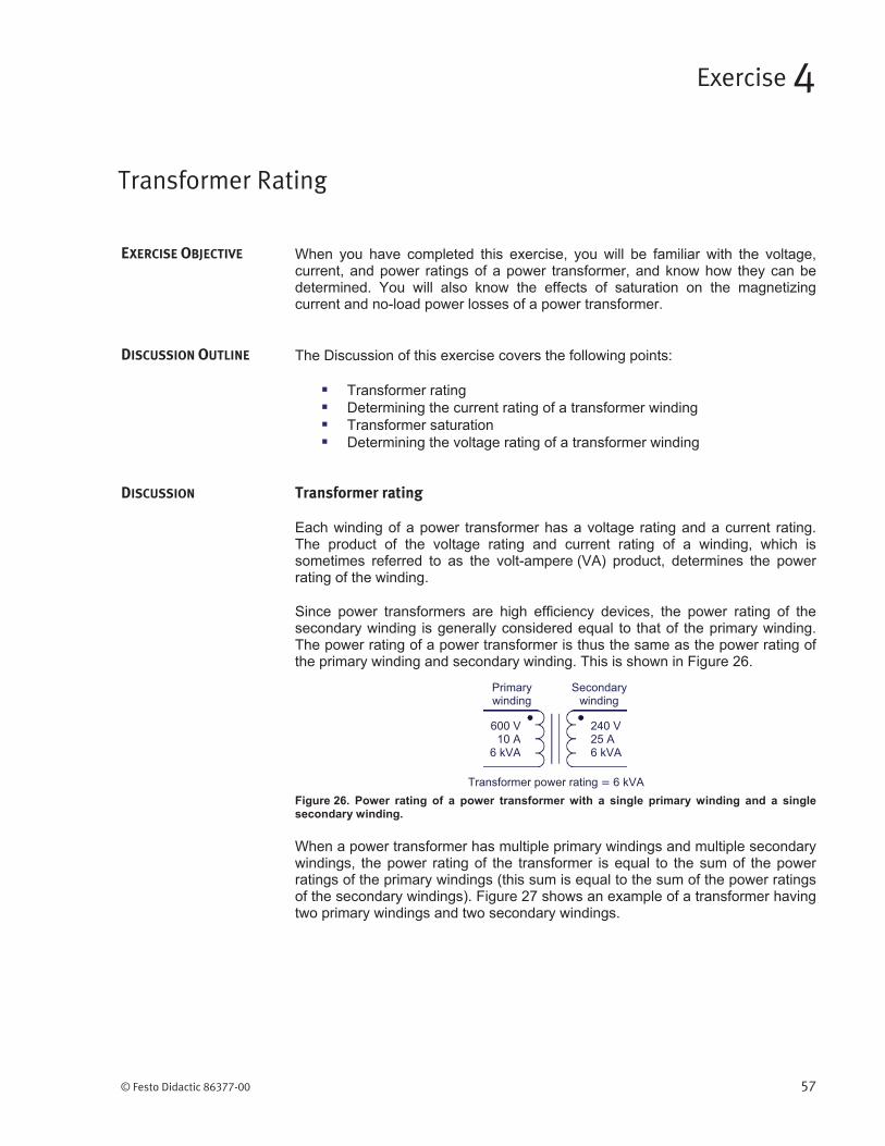
Transformer rating
Transformer Rating
Exercise 4
EXERCISE OBJECTIVE
DISCUSSION OUTLINE
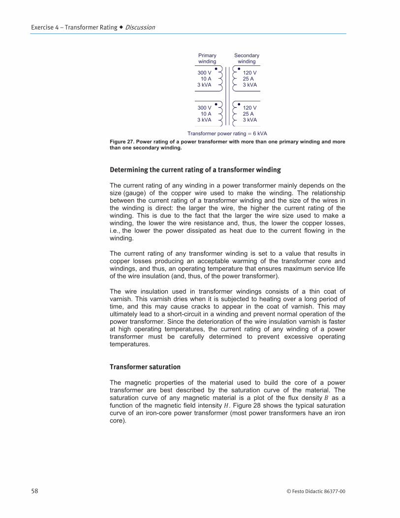
DISCUSSION
Exercise 4 – Transformer Rating Discussion
58 © Festo Didactic 86377-00
Determining the current rating of a transformer winding
Transformer saturation
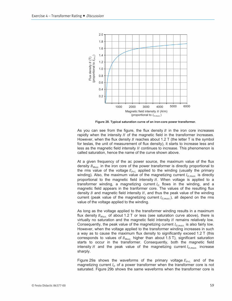
Exercise 4 – Transformer Rating Discussion
© Festo Didactic 86377-00 59
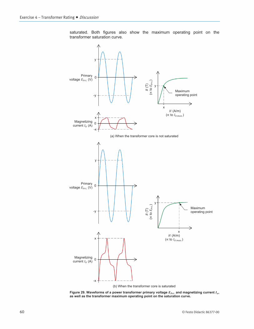
Exercise 4 – Transformer Rating Discussion
60 © Festo Didactic 86377-00

Exercise 4 – Transformer Rating Discussion
© Festo Didactic 86377-00 61
Determining the voltage rating of a transformer winding
Exercise 4 – Transformer Rating Procedure Outline
62 © Festo Didactic 86377-00
Set up and connections
In this section, you will observe the current ratings of the transformer windings indicated on the front panel of the Transformer module, Model 8353, and record their value. You will observe the power transformer in the Transformer module and identify which terminals correspond to the transformer primary windings and which terminals correspond to the transformer secondary windings. You will set up a circuit containing a step-up power transformer without load. You will then set the measuring equipment required to study the transformer voltage, current, and power ratings, as well as the transformer saturation curve.
a Make sure you use the same Transformer module, Model 8353, as in Exercise 3 of this manual by confirming that the module’s serial number is the same as the serial number you recorded in the first step of Exercise 3.
Power Input
Power Input
PROCEDURE OUTLINE
PROCEDURE

Exercise 4 – Transformer Rating Procedure
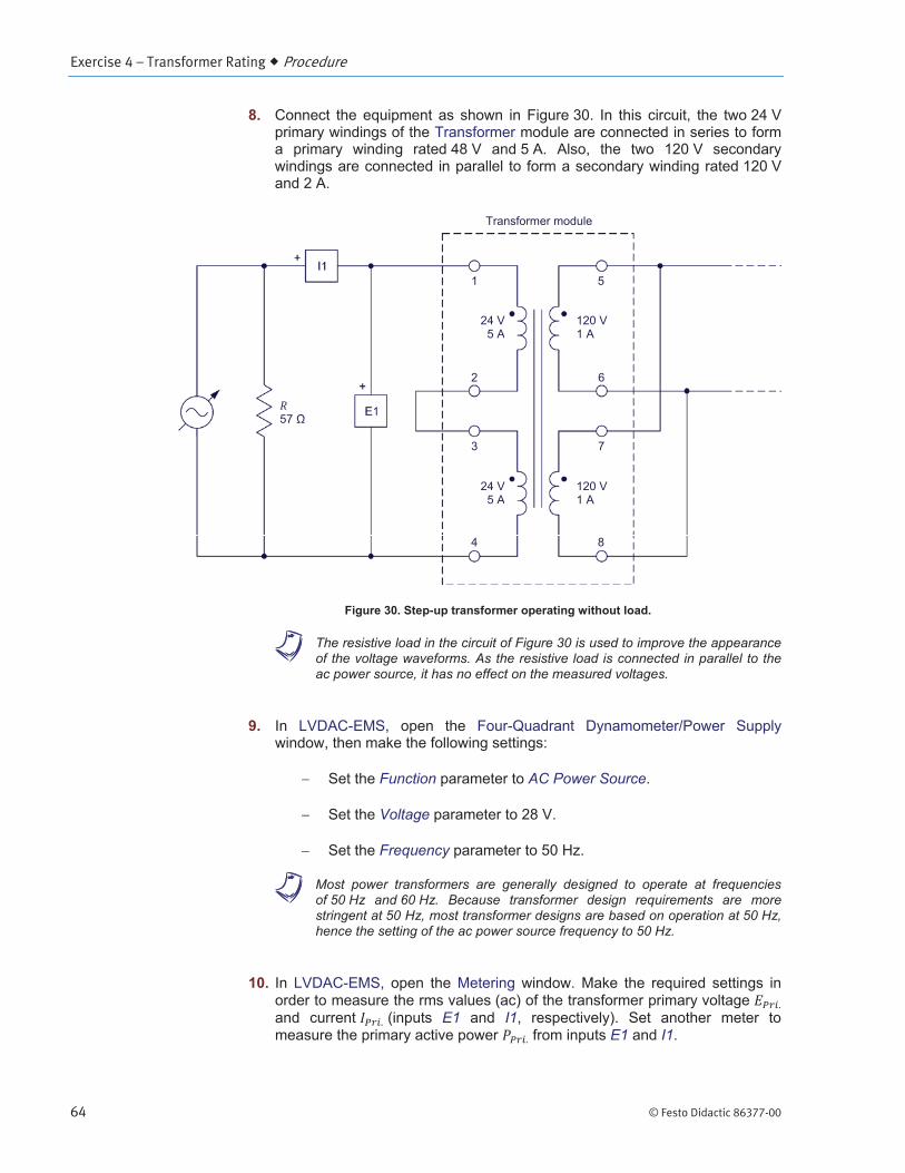
© Festo Didactic 86377-00 63
Operating Mode Power Supply
Computer-Based Instrumentation
OK
a The two terminals of the power transformer with the thinnest wires are used for the thermistor in the transformer. Do not take these terminals into account while answering this question.
Exercise 4 – Transformer Rating Procedure
64 © Festo Didactic 86377-00
a The resistive load in the circuit of Figure 30 is used to improve the appearance of the voltage waveforms. As the resistive load is connected in parallel to the ac power source, it has no effect on the measured voltages.
Function AC Power Source
Voltage
Frequency
a Most power transformers are generally designed to operate at frequencies of 50 Hz and 60 Hz. Because transformer design requirements are more stringent at 50 Hz, most transformer designs are based on operation at 50 Hz, hence the setting of the ac power source frequency to 50 Hz.
E1 I1E1 I1
Exercise 4 – Transformer Rating Procedure
© Festo Didactic 86377-00 65
Transformer saturation
In this section, you will measure the transformer primary voltage, current, and active power when the transformer is not saturated, and analyze the results. You will use the Oscilloscope to observe the waveform of the transformer magnetizing current. You will measure the total harmonic distortion (THD) of the magnetizing current using the Harmonic Analyzer. You will then increase the transformer primary voltage to 56 V and observe what happens to the waveform of the magnetizing current displayed on the Oscilloscope. You will measure the transformer primary voltage, current, and active power when the transformer is saturated, and compare the results with those obtained when the transformer is not saturated. You will measure the THD of the magnetizing current using the Harmonic Analyzer, and compare the result with the THD value you measured when the transformer is not saturated.
AC Power Source Voltage
DC Offset Correction

Exercise 4 – Transformer Rating Procedure
66 © Festo Didactic 86377-00
a The total harmonic distortion (THD) of a waveform indicates the amount of harmonic distortion present in that waveform. The higher the percentage, the more the waveform is distorted due to the presence of harmonics.
Voltage

Exercise 4 – Transformer Rating Procedure
© Festo Didactic 86377-00 67
a The transformer primary voltage is now equal to 56 V, which is nearly 20% above the nominal voltage of the transformer primary windings. The transformer is thus saturated.
Exercise 4 – Transformer Rating Procedure
68 © Festo Didactic 86377-00
Saturation curve of a power transformer
In this section, you will reduce the power transformer primary voltage to 12 V then you will increase the transformer primary voltage to 56 V by steps. For each voltage step, you will record in the Data Table the transformer primary voltage, current (magnetizing current), and active power (no-load power losses), as well as the peak magnetizing current. You will use the measured values to plot the saturation curve of the power transformer.
Voltage
Record Data
Voltage
Voltage
AC Power Source
Exercise 4 – Transformer Rating Procedure
© Festo Didactic 86377-00 69
Voltage rating of transformer windings and transformer power rating
In this section, you will determine at which point on the saturation curve the power transformer operates when the nominal voltage of 48 V is applied to the primary, and analyze the result. You will record the transformer magnetizing current, no-load power losses, and power rating when the nominal voltage of 48 V is applied to the primary. Using the saturation curve, you will determine at which primary voltage value the transformer should operate for maximal efficiency, and determine the corresponding transformer magnetizing current, no-load power losses, and power rating. You will compare these results to the transformer parameters measured at the nominal voltage of 48 V.
Exercise 4 – Transformer Rating Procedure
70 © Festo Didactic 86377-00
Effect of transformer nominal voltage on the power losses and efficiency
In this section, you will connect a resistive load to the step-up transformer. You will start the ac power source and set the transformer primary voltage to the value you determined in the previous section of the exercise (for maximizing transformer efficiency). By varying the resistance of the resistive load, you will increase the transformer secondary (load) current by steps of 0.1 A up to 1.2 A (60% of the nominal load current). For each load current, you will record the transformer primary voltage, current, and active power, as well as the secondary voltage, current, and active power in the Data Table. You will export the results to a spreadsheet application and, for each load current, you will calculate the corresponding transformer power losses and efficiency. On the same graph, you will plot the transformer power losses as a function of the load current, at the nominal voltage (using the values recorded in the previous exercise) and at a voltage maximizing efficiency, and analyze the results. You will do the same for the transformer efficiency as a function of the load current, and analyze the results. Finally, you will compare the transformer load voltage at the nominal voltage and at the voltage you determined for maximizing transformer efficiency, and analyze the results.
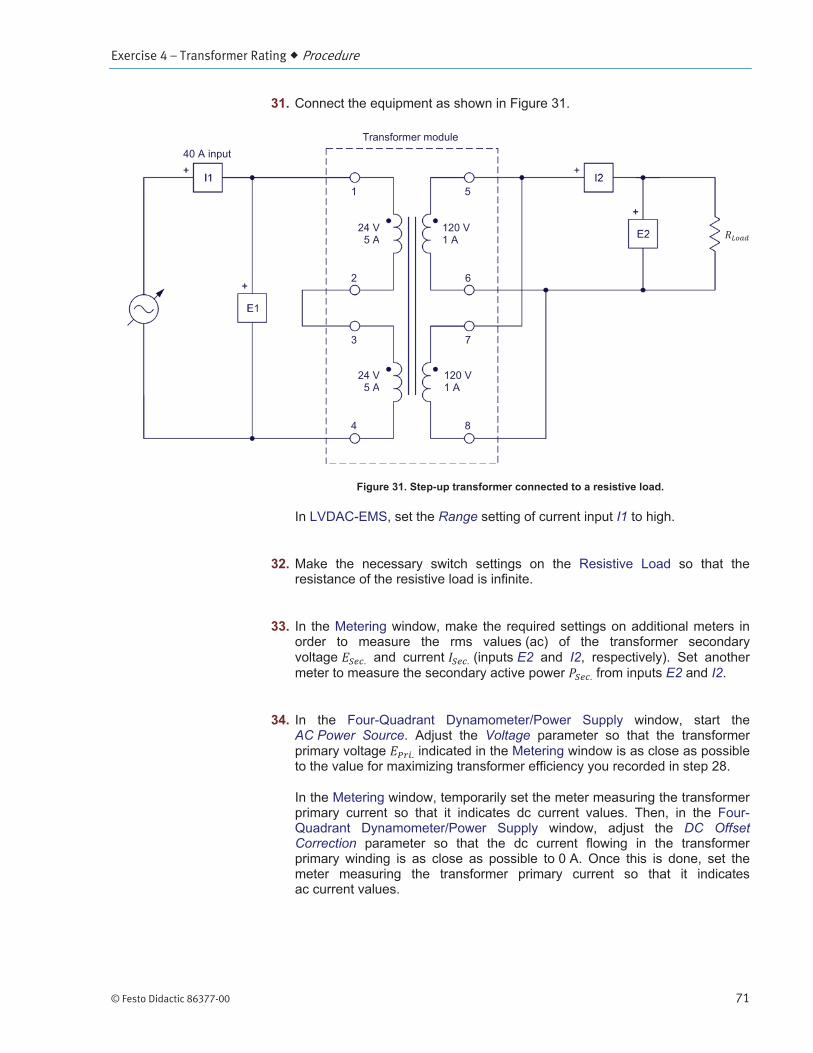
Exercise 4 – Transformer Rating Procedure
© Festo Didactic 86377-00 71
Range I1
E2 I2E2 I2
AC Power Source Voltage
DC Offset Correction
Exercise 4 – Transformer Rating Procedure
72 © Festo Didactic 86377-00
Record Data
Voltage
AC Power Source
Exercise 4 – Transformer Rating Procedure
© Festo Didactic 86377-00 73
Transformer operating temperature
In this section, you will measure the initial temperature of the transformer. You will start the ac power source and set the load resistance so that the load current is equal to about 75% of the nominal full-load current. You will let the ac power source operate for 20 minutes. You will then record the transformer temperature and calculate the transformer temperature increase. These results will be used in the next exercise.
Thermistor InputThermistor Output
a You can also use an external thermometer to achieve the same results if your Transformer module is not equipped with a thermistor input. If so, attach the thermometer probe to the transformer core in order to measure the transformer core temperature.
Exercise 4 – Transformer Rating Conclusion
74 © Festo Didactic 86377-00
Thermistor Type LV Type 2
VoltageAC Power Source Voltage
Voltage
AC Power Source
CONCLUSION
REVIEW QUESTIONS
Exercise 4 – Transformer Rating Review Questions
© Festo Didactic 86377-00 75


© Festo Didactic 86377-00 77
Transformer saturation versus frequency
Effect of Frequency on Transformer Rating
Exercise 5
EXERCISE OBJECTIVE
DISCUSSION OUTLINE
DISCUSSION
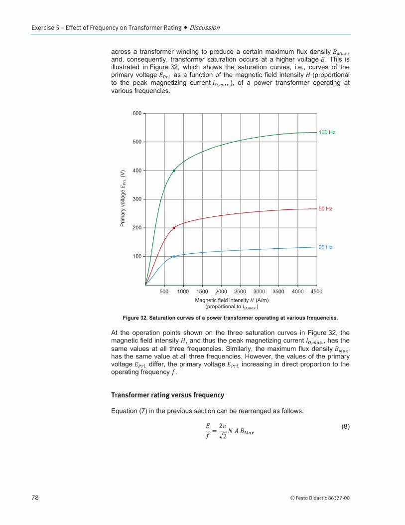
Exercise 5 – Effect of Frequency on Transformer Rating Discussion
78 © Festo Didactic 86377-00
Transformer rating versus frequency
Exercise 5 – Effect of Frequency on Transformer Rating Procedure Outline
© Festo Didactic 86377-00 79
Set up and connections
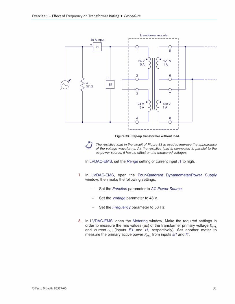
In this section, you will set up a circuit containing a step-up transformer without load. You will then set the measuring equipment required to study the effect of the operating frequency on the transformer voltage and power ratings.
PROCEDURE OUTLINE
PROCEDURE
Exercise 5 – Effect of Frequency on Transformer Rating Procedure
80 © Festo Didactic 86377-00
a Make sure you use the same Transformer module, Model 8353, as in Exercises 3 and 4 of this manual by confirming that the module’s serial number is the same as the serial number you recorded in the first step of Exercise 3.
Power Input
Power Input
Operating Mode Power Supply
Computer-Based Instrumentation
OK
Exercise 5 – Effect of Frequency on Transformer Rating Procedure
© Festo Didactic 86377-00 81
a The resistive load in the circuit of Figure 33 is used to improve the appearance of the voltage waveforms. As the resistive load is connected in parallel to the ac power source, it has no effect on the measured voltages.
Range I1
Function AC Power Source
Voltage
Frequency
E1 I1E1 I1

Exercise 5 – Effect of Frequency on Transformer Rating Procedure
82 © Festo Didactic 86377-00
Transformer operation at a frequency of 50 Hz
In this section, you will start the ac power source. You will display on the Oscilloscope the waveforms of the transformer primary voltage and magnetizing current. You will then measure the transformer primary voltage and magnetizing current when operating at an ac power source frequency of 50 Hz.
AC Power Source Voltage
DC Offset Correction
Effect of frequency on transformer saturation
In this section, you will gradually decrease the ac power source frequency to 35 Hz. While doing so, you will observe on the Oscilloscope what happens to the waveforms of the primary voltage and magnetizing current. You will measure the transformer primary voltage and magnetizing current when operating at an ac power source frequency of 35 Hz. You will set the ac power source frequency back to 50 Hz, then increase it gradually to 75 Hz. While doing so, you will observe on the Oscilloscope what happens to the waveforms of the primary voltage and magnetizing current. You will measure the transformer primary voltage and magnetizing current when operating at an ac power source frequency of 75 Hz, and compare the values to those you obtained at an ac power source frequency of 35 Hz.
FrequencyVoltage

Exercise 5 – Effect of Frequency on Transformer Rating Procedure
© Festo Didactic 86377-00 83
Frequency Voltage
AC Power Source
I1I1
Range I1
AC Power Source
DC Offset
Exercise 5 – Effect of Frequency on Transformer Rating Procedure
84 © Festo Didactic 86377-00
Correction
FrequencyVoltage

Exercise 5 – Effect of Frequency on Transformer Rating Procedure
© Festo Didactic 86377-00 85
Saturation curve of the power transformer at a frequency of 75 Hz
In this section, you will reduce the transformer primary voltage to 18 V then you will increase the transformer primary voltage to 81 V by steps. For each voltage step, you will record in the Data Table the transformer primary voltage, current (magnetizing current), and active power (no-load power losses), as well as the peak magnetizing current. You will plot on the same graph the power transformer saturation curve at ac power source frequencies of 50 Hz (from results recorded in the previous exercise) and 75 Hz, and compare the two saturation curves.
Voltage
Record Data
Voltage
Voltage
AC Power Source

Exercise 5 – Effect of Frequency on Transformer Rating Procedure
86 © Festo Didactic 86377-00
Effect of frequency on the voltage rating of transformer windings and on the transformer power rating
In this section, you will set up a circuit containing a step-up transformer connected to a resistive load. You will make the transformer operate at the nominal voltage and at an ac power source frequency of 50 Hz. You will measure the transformer magnetizing current. You will decrease the resistance of the resistive load so that a current of 1.5 A (75% of the nominal full-load current) flows in the secondary winding. While doing so, you will maintain the transformer primary voltage constant. You will measure the transformer secondary voltage and active power. You will set the resistive load back to infinite. You will then make the transformer operate at an ac power source frequency of 75 Hz, and adjust the primary voltage so that the transformer magnetizing current is virtually equal to the magnetizing current value you recorded at an ac power source frequency of 50 Hz. You will measure the transformer primary voltage, and compare the value with the nominal voltage at an ac power source frequency of 50 Hz. You will decrease the resistance of the resistive load so that a current of 1.5 A flows in the secondary winding. While doing so, you will maintain the transformer primary voltage constant. You will measure the transformer secondary voltage and active power, and compare the values with those obtained at an ac power source frequency of 50 Hz

Exercise 5 – Effect of Frequency on Transformer Rating Procedure
© Festo Didactic 86377-00 87
Range I1
E2 I2E2 I2
VoltageFrequency
AC Power Source Voltage
DC Offset Correction

Exercise 5 – Effect of Frequency on Transformer Rating Procedure
88 © Festo Didactic 86377-00
Voltage
Frequency Voltage
Exercise 5 – Effect of Frequency on Transformer Rating Procedure
© Festo Didactic 86377-00 89
Voltage
a The voltage and power ratings of the Resistive Load are significantly exceeded in this manipulation. It is therefore important that you perform the remainder of this step in less than 2 minutes to avoid damaging the Resistive Load.
AC Power Source
Exercise 5 – Effect of Frequency on Transformer Rating Procedure
90 © Festo Didactic 86377-00
Transformer operating temperature (OPTIONAL)
a This section can only be performed if a second Resistive Load is available. For this reason, it is considered optional.
In this section, you will connect a second load resistor in series with the one in the circuit you set up in the previous section to allow continuous operation at higher voltages. You will measure the initial temperature of the transformer. You will start the ac power source. You will make sure that the transformer primary voltage is equal to the nominal primary voltage determined when operating at an ac power source frequency of 75 Hz and that the load current is equal to about 75% of the nominal load current. You will let the ac power source operate for 20 minutes. You will record the transformer temperature, and calculate the transformer temperature increase. You will then compare the transformer temperature increase when the transformer operates at ac power source frequencies of 50 Hz and 75 Hz using the results you recorded in the previous exercise and in this exercise.
Thermistor InputThermistor Output
Thermistor Type LV Type 2
AC Power Source Voltage

Exercise 5 – Effect of Frequency on Transformer Rating Procedure
© Festo Didactic 86377-00 91
AC Power Source

Exercise 5 – Effect of Frequency on Transformer Rating Conclusion
92 © Festo Didactic 86377-00
CONCLUSION
REVIEW QUESTIONS
© Festo Didactic 86377-00 93
Autotransformer operation
The Autotransformer
Exercise 6
EXERCISE OBJECTIVE
DISCUSSION OUTLINE
DISCUSSION
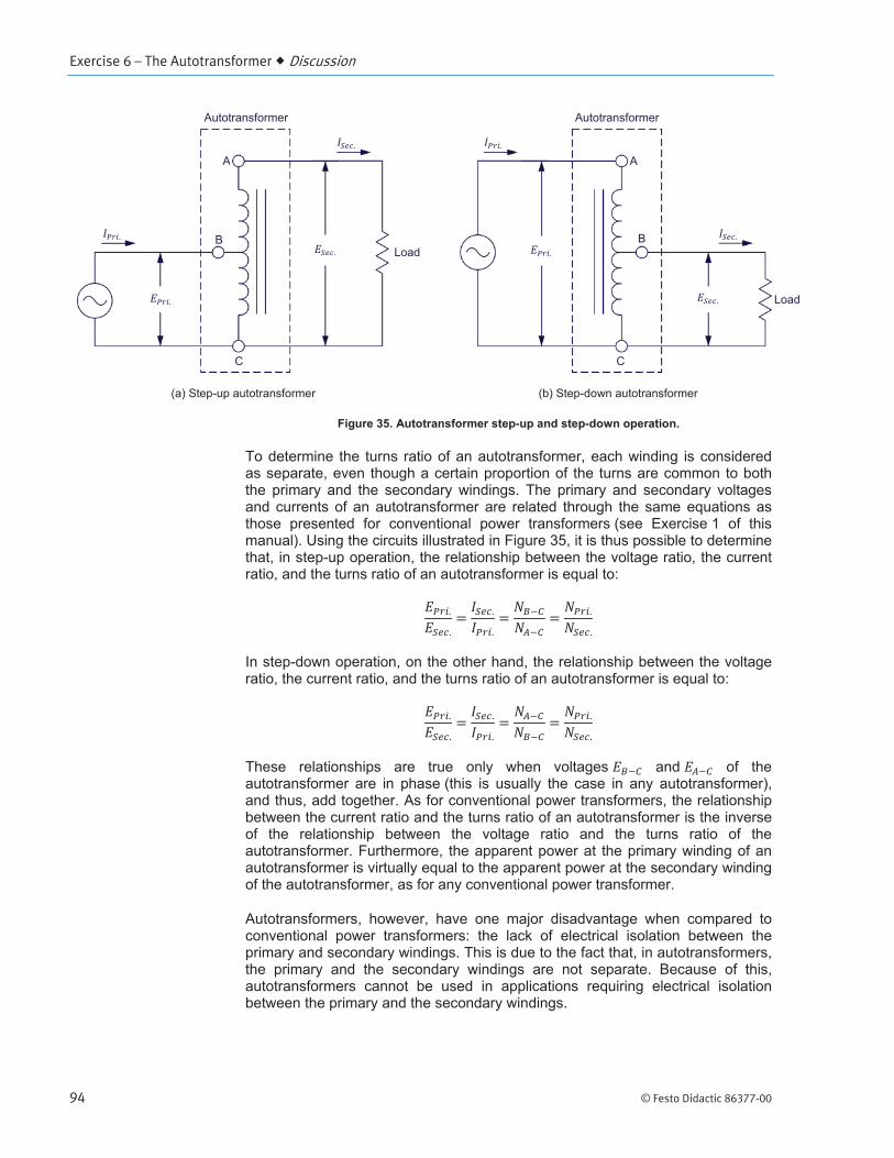
Exercise 6 – The Autotransformer Discussion
94 © Festo Didactic 86377-00

Exercise 6 – The Autotransformer Discussion
© Festo Didactic 86377-00 95
Autotransformer circuit analysis
Step-up autotransformer circuit analysis
Exercise 6 – The Autotransformer Discussion
96 © Festo Didactic 86377-00
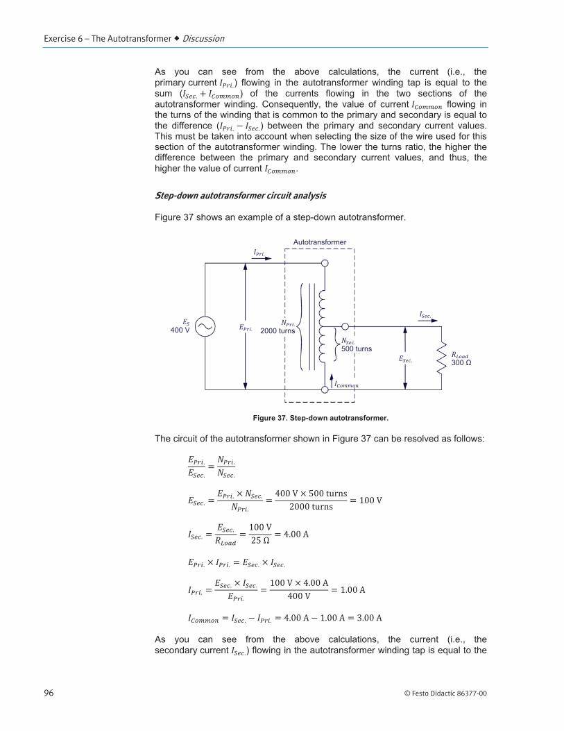
Step-down autotransformer circuit analysis

Exercise 6 – The Autotransformer Discussion
© Festo Didactic 86377-00 97
Power rating of conventional transformers and autotransformers
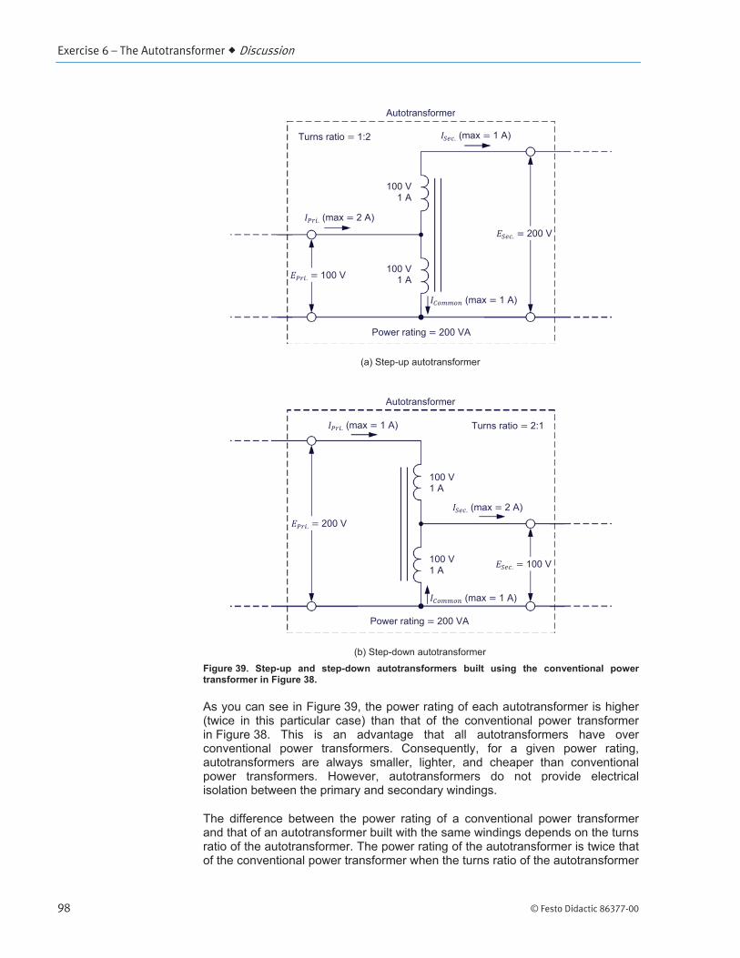
Exercise 6 – The Autotransformer Discussion
98 © Festo Didactic 86377-00
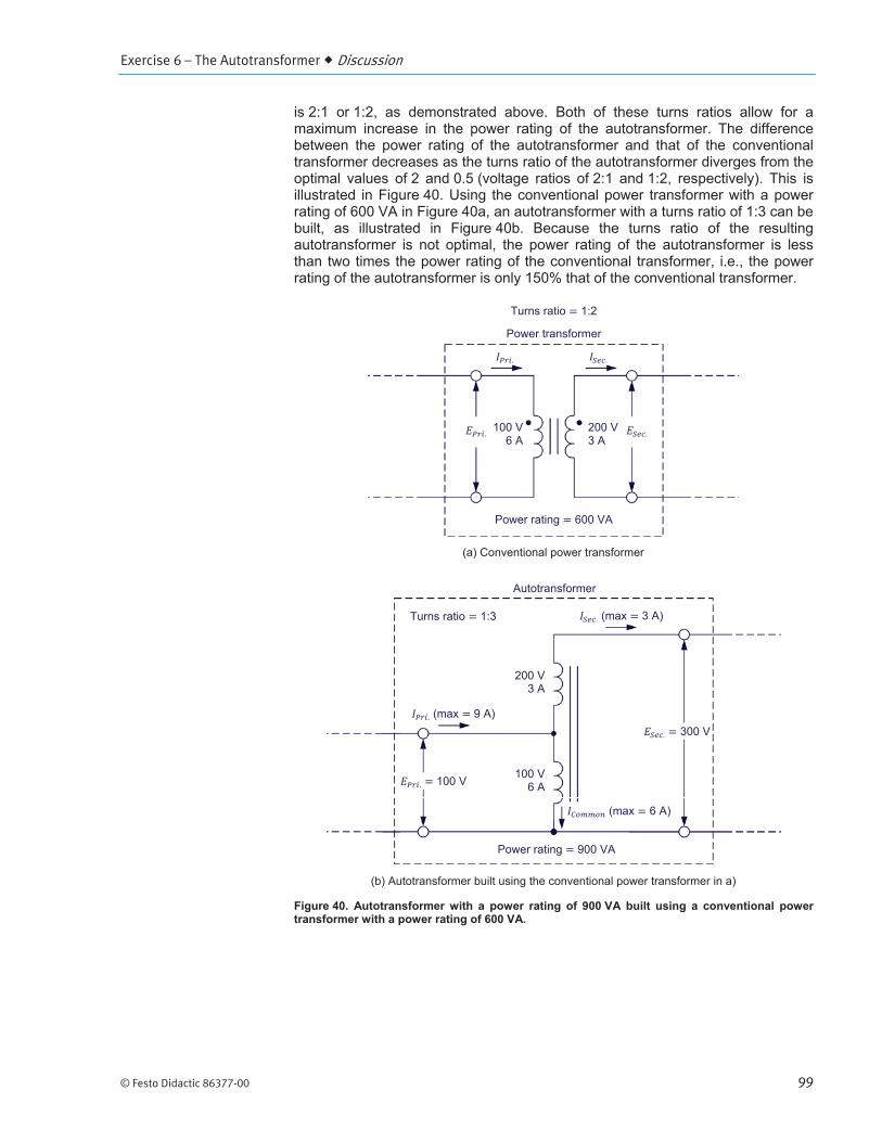
Exercise 6 – The Autotransformer Discussion
© Festo Didactic 86377-00 99

Exercise 6 – The Autotransformer Procedure Outline
100 © Festo Didactic 86377-00
Set up and connections
In this section, you will set up a circuit containing a step-down autotransformer connected to a resistive load. You will determine the autotransformer turns ratio and the secondary voltage when a voltage of 100 V is applied to the primary. You will then set the measuring equipment required to study the operation of autotransformers.
Power Input
Power Input
Operating Mode Power Supply
PROCEDURE OUTLINE
PROCEDURE

Exercise 6 – The Autotransformer Procedure
© Festo Didactic 86377-00 101
Computer-Based Instrumentation
OK

Exercise 6 – The Autotransformer Procedure
102 © Festo Didactic 86377-00
a The number of turns in each of the two 24 V – 5 A windings of the power transformer in the Transformer module is 57 turns. The number of turns in each of the two 120 V – 1 A windings of the transformer is 285 turns.
Function AC Power Source
Voltage
Frequency
E1 I1E2 I2
I3
Operation of a step-down autotransformer
In this section, you will start the ac power source. You will set the resistance of the resistive load to 57 . You will measure the autotransformer voltages and currents, and analyze the results. You will determine the autotransformer maximum secondary (load) voltage and current, as well as its power rating.
AC Power Source Voltage
DC Offset Correction

Exercise 6 – The Autotransformer Procedure
© Festo Didactic 86377-00 103
Voltage
a It is possible that you may not be able to set the transformer primary voltage indicated in the Metering window to 100 V because you have reached the voltage limit of the Four-Quadrant Dynamometer/Power Supply. If so, simply set the parameter to the highest possible value before proceeding to the next step.

Exercise 6 – The Autotransformer Procedure
104 © Festo Didactic 86377-00
AC Power Source
Operation of a step-up autotransformer
In this section, you will set up a circuit containing a step-up autotransformer connected to a resistive load. You will determine the autotransformer turns ratio and the secondary voltage when a voltage of 50 V is applied to the primary. You will start the ac power source. You will set the resistance of the resistive load to 200 . You will measure the autotransformer voltages and currents, and analyze the results. You will determine the autotransformer maximum secondary (load) voltage and current, as well as its power rating.
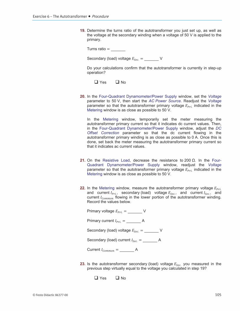
Exercise 6 – The Autotransformer Procedure
© Festo Didactic 86377-00 105
VoltageAC Power Source Voltage
DC Offset Correction
Voltage

Exercise 6 – The Autotransformer Procedure
106 © Festo Didactic 86377-00
AC Power Source
Comparing the power rating of an autotransformer to that of a conventional power transformer of the same size
In this section, you will calculate the power rating of a conventional transformer built using the same windings of the transformer module that you used to implement the step-down and step-up autotransformers studied in the previous sections. You will compare the power rating of these autotransformers with the power rating of the conventional transformer built using the same windings.
Exercise 6 – The Autotransformer Procedure
© Festo Didactic 86377-00 107
Effect of the turns ratio on the power rating of autotransformers
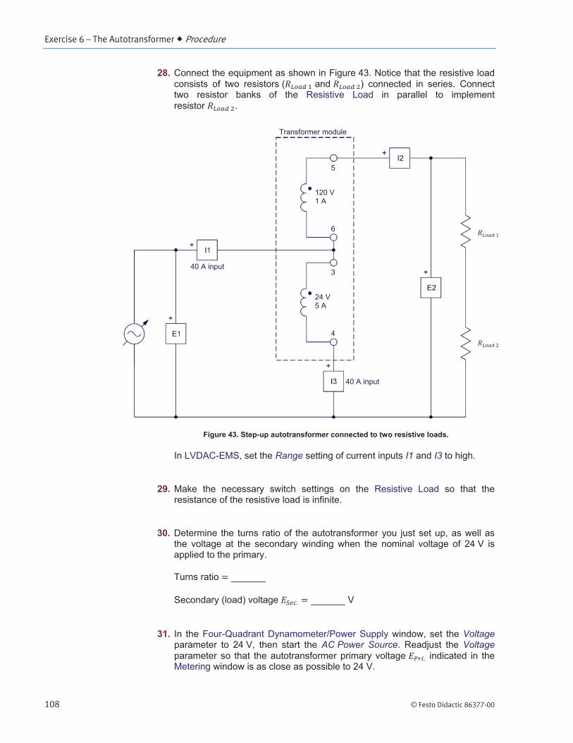
In this section, you will set up a circuit containing a step-up autotransformer connected to a resistive load. You will determine the autotransformer turns ratio and the secondary (load) voltage when a voltage of 24 V is applied to the primary. You will start the ac power source. You will set the resistance of the resistive load to 257 . You will measure the autotransformer voltages and currents, and analyze the results. You will determine the autotransformer maximum secondary (load) current, as well as its power rating. You will calculate the power rating of a conventional transformer built using the same windings as the autotransformer. You will confirm that the power rating of the autotransformer is still higher than that of the conventional transformer built with the same windings. Finally, you will compare the increase in the power rating for autotransformers with turns ratios of 2:1, 1:2, and 1:6 in comparison to a conventional transformer built using the same respective windings.
Exercise 6 – The Autotransformer Procedure
108 © Festo Didactic 86377-00
Range I1 I3
VoltageAC Power Source Voltage

Exercise 6 – The Autotransformer Procedure
© Festo Didactic 86377-00 109
DC Offset Correction
Voltage
Exercise 6 – The Autotransformer Conclusion
110 © Festo Didactic 86377-00
AC Power Source
CONCLUSION
REVIEW QUESTIONS
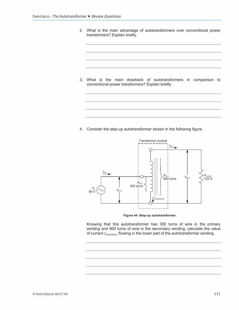
Exercise 6 – The Autotransformer Review Questions
© Festo Didactic 86377-00 111

Exercise 6 – The Autotransformer Review Questions
112 © Festo Didactic 86377-00
© Festo Didactic 86377-00 113
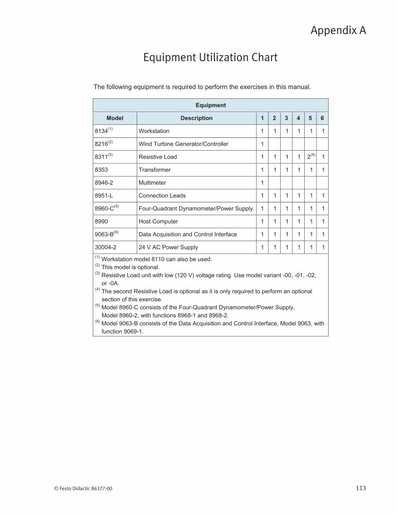
The following equipment is required to perform the exercises in this manual.
Equipment
Model Description 1 2 3 4 5 6
8134(1) Workstation 1 1 1 1 1 1
8216(2) Wind Turbine Generator/Controller 1
8311(3) Resistive Load 1 1 1 1 2(4) 1
8353 Transformer 1 1 1 1 1 1
8946-2 Multimeter 1
8951-L Connection Leads 1 1 1 1 1 1
8960-C(5) Four-Quadrant Dynamometer/Power Supply 1 1 1 1 1 1
8990 Host Computer 1 1 1 1 1 1
9063-B(6) Data Acquisition and Control Interface 1 1 1 1 1 1
30004-2 24 V AC Power Supply 1 1 1 1 1 1
(1) Workstation model 8110 can also be used. (2) This model is optional. (3) Resistive Load unit with low (120 V) voltage rating. Use model variant -00, -01, -02, or -0A. (4) The second Resistive Load is optional as it is only required to perform an optional section of this exercise. (5) Model 8960-C consists of the Four-Quadrant Dynamometer/Power Supply, Model 8960-2, with functions 8968-1 and 8968-2. (6) Model 9063-B consists of the Data Acquisition and Control Interface, Model 9063, with function 9069-1.
Equipment Utilization Chart
Appendix A


© Festo Didactic 86377-00 115
Glossary of New Terms
Appendix B

Appendix B Glossary of New Terms
116 © Festo Didactic 86377-00
© Festo Didactic 86377-00 117
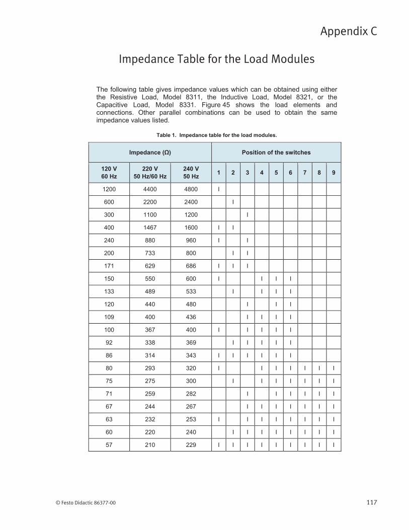
Impedance Table for the Load Modules
Appendix C

Appendix C Impedance Table for the Load Modules
118 © Festo Didactic 86377-00
© Festo Didactic 86377-00 119
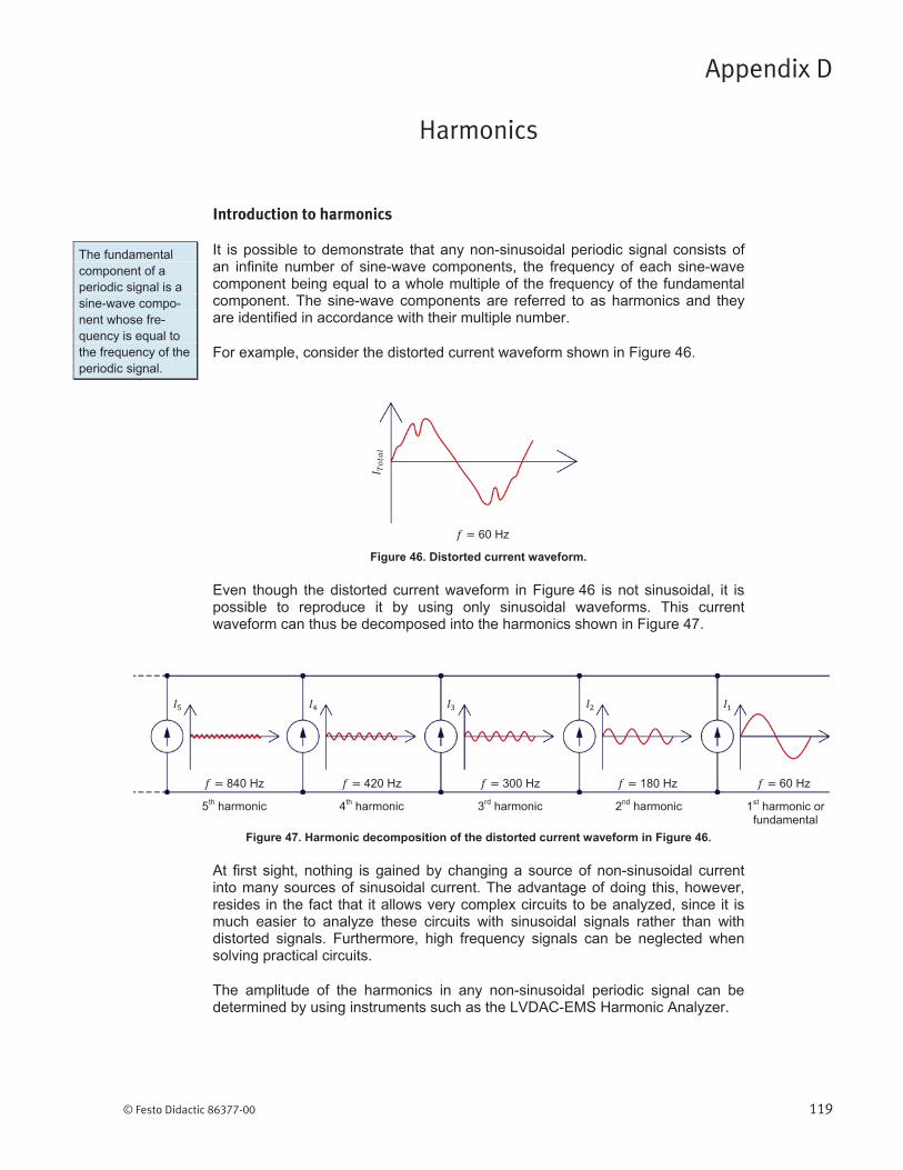
Introduction to harmonics
Harmonics
Appendix D
Appendix D Harmonics
120 © Festo Didactic 86377-00
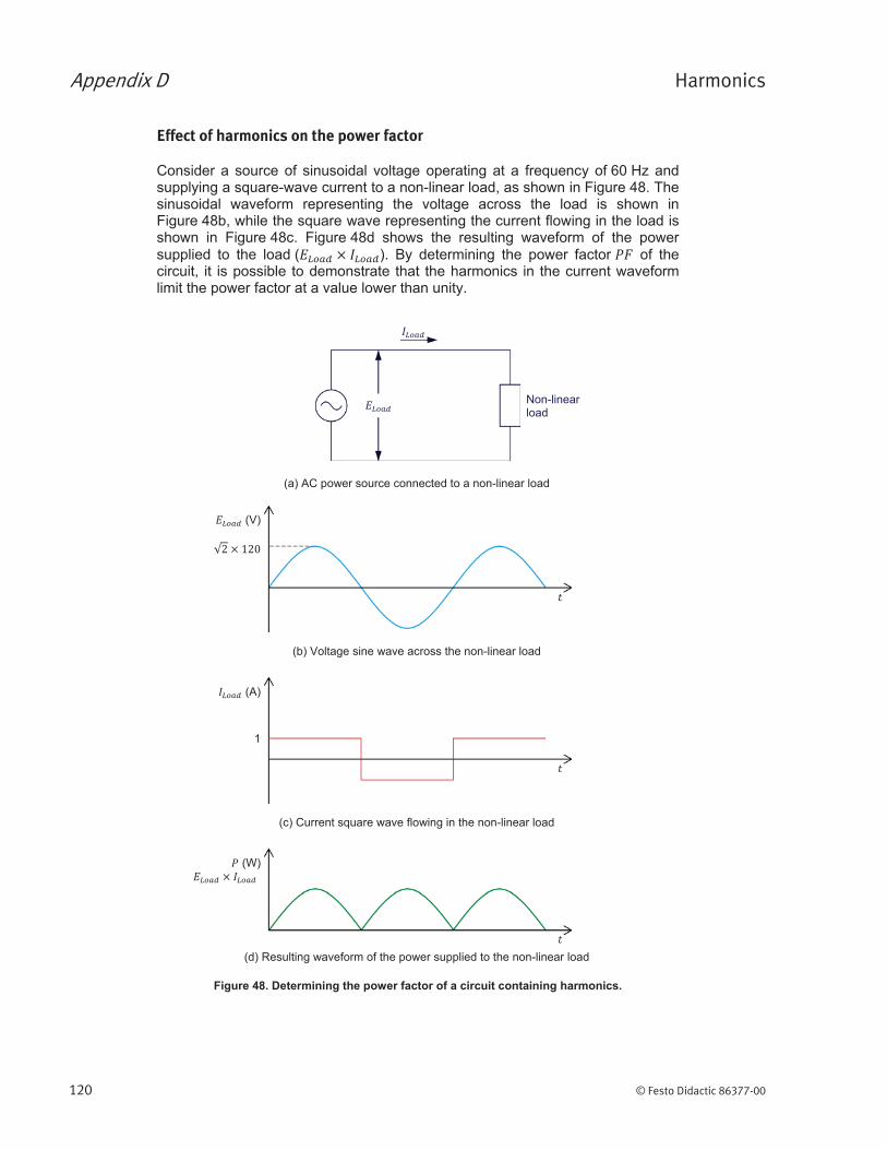
Effect of harmonics on the power factor
Appendix D Harmonics
© Festo Didactic 86377-00 121
a The average value of a rectified sine wave is expressed by , where is the amplitude of the signal.

© Festo Didactic 86377-00 123
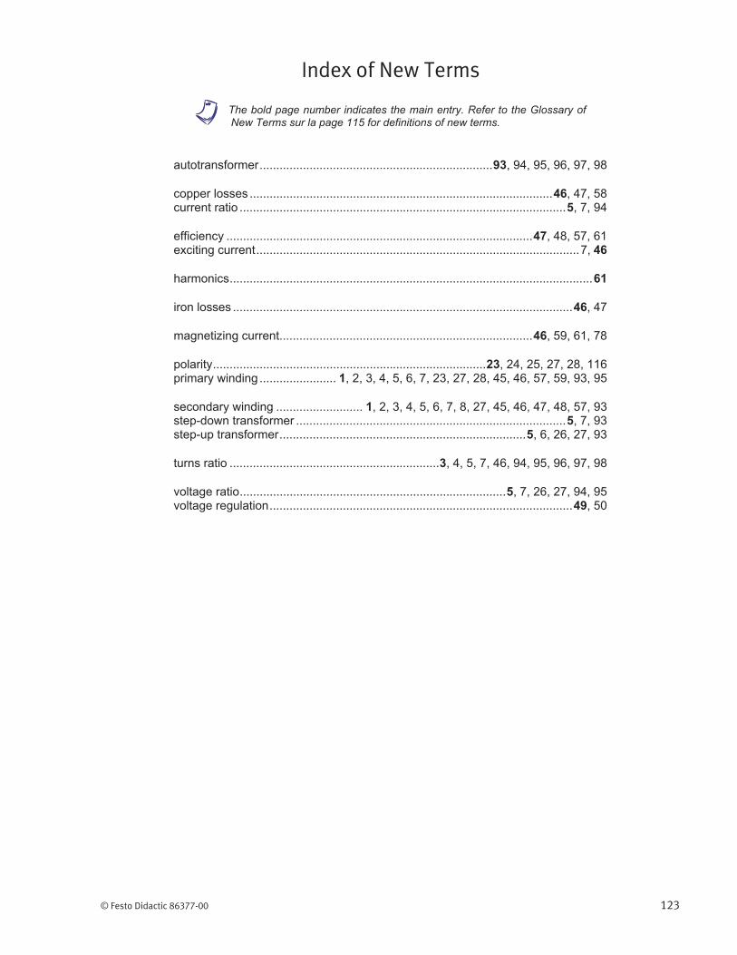
Index of New Terms
a The bold page number indicates the main entry. Refer to the Glossary of New Terms sur la page 115 for definitions of new terms.


© Festo Didactic 86377-00 125
Bibliography
Introductory Circuit Analysis
Electrical Machines, Drives, and Power Systems