Embed Size (px)
Citation preview

Electricity and New Energy
Ni-MH Batteries
Courseware Sample 86354-F0

Order no.: 86354-10 Revision level: 06/2016
By the staff of Festo Didactic
© Festo Didactic Ltée/Ltd, Quebec, Canada 2010 Internet: www.festo-didactic.com e-mail: [email protected]
Printed in Canada All rights reserved ISBN 978-2-89640-451-3 (Printed version) ISBN 978-2-89747-235-1 (CD-ROM) Legal Deposit – Bibliothèque et Archives nationales du Québec, 2010 Legal Deposit – Library and Archives Canada, 2010
The purchaser shall receive a single right of use which is non-exclusive, non-time-limited and limited geographically to use at the purchaser's site/location as follows.
The purchaser shall be entitled to use the work to train his/her staff at the purchaser’s site/location and shall also be entitled to use parts of the copyright material as the basis for the production of his/her own training documentation for the training of his/her staff at the purchaser’s site/location with acknowledgement of source and to make copies for this purpose. In the case of schools/technical colleges, training centers, and universities, the right of use shall also include use by school and college students and trainees at the purchaser’s site/location for teaching purposes.
The right of use shall in all cases exclude the right to publish the copyright material or to make this available for use on intranet, Internet and LMS platforms and databases such as Moodle, which allow access by a wide variety of users, including those outside of the purchaser’s site/location.
Entitlement to other rights relating to reproductions, copies, adaptations, translations, microfilming and transfer to and storage and processing in electronic systems, no matter whether in whole or in part, shall require the prior consent of Festo Didactic.
Information in this document is subject to change without notice and does not represent a commitment on the part of Festo Didactic. The Festo materials described in this document are furnished under a license agreement or a nondisclosure agreement.
Festo Didactic recognizes product names as trademarks or registered trademarks of their respective holders.
All other trademarks are the property of their respective owners. Other trademarks and trade names may be used in this document to refer to either the entity claiming the marks and names or their products. Festo Didactic disclaims any proprietary interest in trademarks and trade names other than its own.
© Festo Didactic 86354-10 III
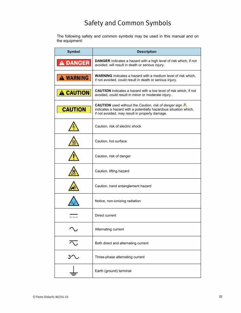
Safety and Common Symbols
The following safety and common symbols may be used in this manual and on the equipment:
Symbol Description
DANGER indicates a hazard with a high level of risk which, if not avoided, will result in death or serious injury.
WARNING indicates a hazard with a medium level of risk which, if not avoided, could result in death or serious injury.
CAUTION indicates a hazard with a low level of risk which, if not avoided, could result in minor or moderate injury.
CAUTION used without the Caution, risk of danger sign , indicates a hazard with a potentially hazardous situation which, if not avoided, may result in property damage.
Caution, risk of electric shock
Caution, hot surface
Caution, risk of danger
Caution, lifting hazard
Caution, hand entanglement hazard
Notice, non-ionizing radiation
Direct current
Alternating current
Both direct and alternating current
Three-phase alternating current
Earth (ground) terminal

Safety and Common Symbols
IV © Festo Didactic 86354-10
Symbol Description
Protective conductor terminal
Frame or chassis terminal
Equipotentiality
On (supply)
Off (supply)
Equipment protected throughout by double insulation or reinforced insulation
In position of a bi-stable push control
Out position of a bi-stable push control
© Festo Didactic 86354-10 V
Table of Contents
Preface .................................................................................................................. IX
About This Manual ................................................................................................ XI
To the Instructor .................................................................................................. XIII
Introduction Ni-MH Batteries ............................................................................ 1
DISCUSSION OF FUNDAMENTALS ....................................................... 1Storing electrical energy using batteries ................................. 1
Exercise 1 Battery Fundamentals ................................................................. 3
DISCUSSION ..................................................................................... 3Definition .................................................................................. 3Battery types ............................................................................ 3Cell versus battery ................................................................... 4Operation during discharge and charge cycles ....................... 4Open-circuit voltage ................................................................. 6State of charge ........................................................................ 7Voltage regulation and internal resistance .............................. 7Battery capacity ....................................................................... 9Cycle life and depth of discharge .......................................... 11
PROCEDURE .................................................................................. 12Set up and connections ......................................................... 12Battery state-of-charge evaluation ......................................... 13Battery voltage regulation curve ............................................ 13Battery internal resistance evaluation ................................... 17Battery voltage and energy supplied during a discharge at 0.5 5 .................................................................................. 18
Exercise 2 Battery Capacity Versus Discharge Rate ................................ 27
DISCUSSION ................................................................................... 27Battery cell voltage versus discharge rate ............................. 27Temperature versus available capacity ................................. 30Memory effect ........................................................................ 31Energy supplied during a discharge cycle ............................. 31Specific energy and energy density....................................... 32
PROCEDURE .................................................................................. 33Set up and connections ......................................................... 33Battery voltage and energy supplied during a discharge at 1 5 ..................................................................................... 35Battery voltage and energy supplied during a discharge at 2 5 ..................................................................................... 38Battery capacity versus discharge rate ................................. 42Specific energy and energy density....................................... 45

Table of Contents
VI © Festo Didactic 86354-10
Exercise 3 Battery Charging Fundamentals............................................... 49
DISCUSSION ................................................................................... 49Charging fundamentals ......................................................... 49Battery voltage and temperature profiles during charge ....... 50Risks related to overcharging a Ni-MH battery ...................... 53Charge control and efficiency ................................................ 54
PROCEDURE .................................................................................. 55Set up and connections ......................................................... 55Full battery discharge ............................................................ 56Battery voltage and temperature profiles at a charge rate of 0.5 5 .................................................................................. 58
Exercise 4 Battery Charging Methods ........................................................ 73
DISCUSSION ................................................................................... 73Charge-control techniques .................................................... 73
Timed charge ........................................................................... 73Voltage drop (- V) .................................................................... 73Voltage plateau (0 V) .............................................................. 74Temperature cutoff (TCO) ........................................................ 74Rate of temperature increase ( T°/ t) ..................................... 75
Charge-control technique and cycle life ................................ 75Charging methods ................................................................. 75
Low-rate charge ....................................................................... 75Quick charge ............................................................................ 75Fast charge .............................................................................. 76Trickle charge ........................................................................... 76Three-step charge .................................................................... 76
PROCEDURE .................................................................................. 77Set up and connections ......................................................... 77Full battery discharge ............................................................ 78Battery charge at 0.5C5 using the dT°/dt charge-control technique ............................................................................... 80Slow battery charge using a low-rate, constant-current charging method (OPTIONAL) .............................................. 91Three-step charge (OPTIONAL) .......................................... 105
Appendix A Equipment Utilization Chart .................................................... 123
Appendix B Glossary of New Terms ........................................................... 125
Table of Contents
© Festo Didactic 86354-10 VII
Appendix C Battery Maintenance ................................................................ 127Preparation of the batteries before a lab session ................ 127Battery charge ..................................................................... 127
First option (preferred) ........................................................... 127Second option ........................................................................ 129
Battery maintenance ............................................................ 130
Index of New Terms ........................................................................................... 131
Acronyms ........................................................................................................... 133
Bibliography ....................................................................................................... 135


© Festo Didactic 86354-10 IX
Preface
The production of energy using renewable natural resources such as wind, sunlight, rain, tides, geothermal heat, etc., has gained much importance in recent years as it is an effective means of reducing greenhouse gas (GHG) emissions. The need for innovative technologies to make the grid smarter has recently emerged as a major trend, as the increase in electrical power demand observed worldwide makes it harder for the actual grid in many countries to keep up with demand. Furthermore, electric vehicles (from bicycles to cars) are developed and marketed with more and more success in many countries all over the world.
To answer the increasingly diversified needs for training in the wide field of electrical energy, the Electric Power Technology Training Program was developed as a modular study program for technical institutes, colleges, and universities. The program is shown below as a flow chart, with each box in the flow chart representing a course.
The Electric Power Technology Training Program.

Preface
X © Festo Didactic 86354-10
The program starts with a variety of courses providing in-depth coverage of basic topics related to the field of electrical energy such as ac and dc power circuits, power transformers, rotating machines, ac power transmission lines, and power electronics. The program then builds on the knowledge gained by the student through these basic courses to provide training in more advanced subjects such as home energy production from renewable resources (wind and sunlight), large-scale electricity production from hydropower, large-scale electricity production from wind power (doubly-fed induction generator [DFIG], synchronous generator, and asynchronous generator technologies), smart-grid technologies (SVC, STATCOM, HVDC transmission, etc.), storage of electrical energy in batteries, and drive systems for small electric vehicles and cars.
We invite readers of this manual to send us their tips, feedback, and sugges-tions for improving the book.
Please send these to [email protected].
The authors and Festo Didactic look forward to your comments.

© Festo Didactic 86354-10 XI
About This Manual
Batteries store electricity in a chemical form, inside a closed-energy system. Some batteries can be re-charged and re-used as a power source in small appliances, machinery, and remote locations. Advances in battery technology may one day help in achieving greater use of clean energy produced from renewable resources such as sunlight, wind, rain, tide, and others.
The Ni-MI Batteries course teaches the basic concepts of Ni-MI batteries. At the beginning of the course, students are introduced to the concepts of voltage regulation, internal resistance, capacity, depth of discharge, and cycle life of Ni-MI batteries. Students then learn about and experiment with both the discharge characteristics and the most common charging methods and charge-control techniques of Ni-MI batteries.
Figure 1. Typical commercially available Ni-MI batteries with corresponding Ni-MI battery charger.

About This Manual
XII © Festo Didactic 86354-10
Safety considerations
Safety symbols that may be used in this manual and on the equipment are listed in the Safety Symbols table at the beginning of the manual.
Safety procedures related to the tasks that you will be asked to perform are indicated in each exercise.
Make sure that you are wearing appropriate protective equipment when performing the tasks. You should never perform a task if you have any reason to think that a manipulation could be dangerous for you or your teammates.
Prerequisite
As a prerequisite to this course, you should have read the manual titled DC Power Circuits, p.n. 86350.
Systems of units
Units are expressed using the International System of Units (SI) followed by the units expressed in the U.S. customary system of units (between parentheses).
© Festo Didactic 86354-10 XIII
To the Instructor
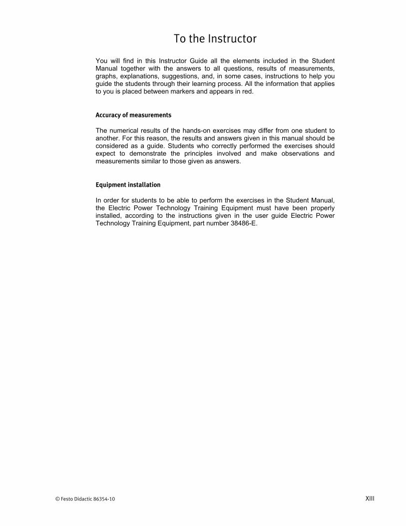
You will find in this Instructor Guide all the elements included in the Student Manual together with the answers to all questions, results of measurements, graphs, explanations, suggestions, and, in some cases, instructions to help you guide the students through their learning process. All the information that applies to you is placed between markers and appears in red.
Accuracy of measurements
The numerical results of the hands-on exercises may differ from one student to another. For this reason, the results and answers given in this manual should be considered as a guide. Students who correctly performed the exercises should expect to demonstrate the principles involved and make observations and measurements similar to those given as answers.
Equipment installation
In order for students to be able to perform the exercises in the Student Manual, the Electric Power Technology Training Equipment must have been properly installed, according to the instructions given in the user guide Electric Power Technology Training Equipment, part number 38486-E.


Sample Exercise
Extracted from
the Student Manual
and the Instructor Guide


© Festo Didactic 86354-10 27
When you have completed this exercise, you will be familiar with the effects of the discharge rate and battery temperature on the capacity and voltage of a Ni-MH battery. You will know how to calculate the energy supplied during a discharge cycle. You will also know what the specific energy and the energy density of a battery are, and how to determine these two parameters.
The Discussion of this exercise covers the following points:
Battery cell voltage versus discharge rate Temperature versus available capacity Memory effect Energy supplied during a discharge cycle Specific energy and energy density
Battery cell voltage versus discharge rate
Figure 14 shows a family of discharge characteristic curves of a Ni-MH battery obtained at various discharge rates. Notice that these curves represent the voltage measured across each cell in the battery. The final voltage or cutoff voltage (1 V in the present case) does not vary as a function of the discharge rate. Also note that this family of curves is relative to the discharge characteristic curve obtained at a discharge rate of 0.2 , i.e., the discharge rate commonly used to establish the nominal capacity of Ni-MH batteries.
Battery Capacity Versus Discharge Rate
Exercise 2
EXERCISE OBJECTIVE
DISCUSSION OUTLINE
DISCUSSION

Exercise 2 – Battery Capacity Versus Discharge Rate Discussion
28 © Festo Didactic 86354-10
Figure 14. Family of discharge characteristic curves of a Ni-MH battery obtained at various discharge rates.
Table 3 shows the discharge time and relative battery capacity for each discharge characteristic curve in Figure 14. The capacity of a Ni-MH battery decreases little as the discharge rate increases. In fact, even with a discharge rate of 3 (15 times the optimal discharge rate of 0.2 ), the relative battery capacity is still only 15% below its nominal capacity.
Table 3. Discharge time and relative battery capacity versus discharge rate.
Discharge rate 0.2 1 2 3
Discharge time (h) 5 0.95 0.45 0.28
Relative battery capacity (% of ) 100 95 90 85
Percent of ampere-hour capacity
Cel
l Vol
tage
(V)
3
2
1
0.2
Cutoff voltage

Exercise 2 – Battery Capacity Versus Discharge Rate Discussion
© Festo Didactic 86354-10 29
Figure 15 shows a curve of the relative capacity of a Ni-MH battery as a function of the discharge rate. Notice that the relative capacity of the Ni-MH battery is still more than 80% of the nominal capacity even when the discharge rate is as high as 3 . In comparison, the relative capacity of a lead-acid battery at a discharge rate of 3 is generally only 50% to 60% of the rated capacity.
Figure 15. Relative capacity of a Ni-MH battery versus discharge rate.
Discharge rate
Rel
ativ
e ca
paci
ty (%
)
85% at 3

Exercise 2 – Battery Capacity Versus Discharge Rate Discussion
30 © Festo Didactic 86354-10
Temperature versus available capacity
Figure 16 illustrates the effect of temperature on the available relative capacity of Ni-MH batteries at various discharge rates. As shown in the figure, Ni-MH batteries maintain their capacity over a wide range of discharge rates when operated at room temperature (20°C or 68°F and higher). However, the available capacity decreases fairly rapidly as the temperature goes below room temperature, especially at high discharge rates (1 and higher). This is due to the progressively increasing internal resistance of Ni-MH batteries at lower temperatures.
Figure 16. Relative capacity of a Ni-MH battery versus temperature at various discharge rates.
Temperature (°C)
Temperature (°F)
3
2
1
0.2
Rel
ativ
e ca
paci
ty (%
)

Exercise 2 – Battery Capacity Versus Discharge Rate Discussion
© Festo Didactic 86354-10 31
Memory effect
The memory effect is a reversible drop in voltage and loss of capacity that may occur when a Ni-MH battery is repeatedly discharged partially and recharged without the benefit of a full discharge in between. This phenomenon is also called voltage depression and can be reversed by performing a few subsequent full-discharge cycles. Figure 17 shows the effect of partial-discharge cycles on the cell voltage and capacity of a Ni-MH battery, as well as the reversal of this effect through repetitive full-discharge cycles.
Figure 17. Voltage depression during partial cycling on a Ni-MH battery.
In Figure 17, after a full-discharge cycle (cycle 1), the Ni-MH battery went through a series of 18 partial-discharge cycles (cycles 2 to 18). On the subsequent full-discharge cycle (cycle 19), the observed voltage and capacity are significantly lower than those observed in cycle 1. However, after a few full-discharge cycles (cycles 20 and 21), the voltage and capacity of the battery are nearly restored to their initial values.
Energy supplied during a discharge cycle
Each discharge characteristic curve can be used to determine the amount of energy that a battery releases during a complete discharge. This is carried out by determining the average battery voltage during the complete discharge, multiplying this voltage by the discharge current to find the average power, and then multiplying the calculated average power by the discharge time. The released energy is expressed in watt-hours (W·h).
A watt-hour (W·h) is a unit of energy, equal to the work done by a power of one watt (1 W) acting for one hour. Note that the symbol “Wh” is also widely used to represent the watt-hour.
Time (hrs)
Vol
tage
(V)
Cycle Discharge 1 Full
2-18 Partial 19 Full
20-21 Full
Cycle 19
Cycle 20 Cycle 21 Cycle 1
Cycle 18Cycle 13
Cycle 8
Cycle 2 Cycle 3

Exercise 2 – Battery Capacity Versus Discharge Rate Discussion
32 © Festo Didactic 86354-10
Example
Suppose a Ni-MH battery having a capacity of 50 Ah is discharged at a rate of 0.2 , i.e., a constant current of 10 A. Also suppose that the average voltage during the discharge is 12 V. In this case, the average power the battery delivers is equal to: 12 V 10 A 120 W. The energy supplied during the complete discharge cycle of 5 hours is thus equal to: 120 W 5 h 600 Wh.
Specific energy and energy density
The energy contained in a battery is often expressed as a ratio related to either the battery weight or volume. The ratio of battery energy to battery weight, called specific energy, is calculated by dividing the energy supplied by the battery during a complete discharge cycle by the battery’s weight. The specific energy of Ni-MH batteries currently available does not exceed 80 Wh/kg (36.3 Wh/lb). This is about twice as much as lead-acid batteries (40 Wh/kg or 18.1 Wh/lb), but only half the specific energy of Li-ion batteries (160 Wh/kg or 75.6 Wh/lb).
The ratio of battery energy to battery volume, called energy density, is calculated by dividing the energy supplied by the battery during a complete discharge cycle by the battery’s volume. The energy density of currently available Ni-MH batteries does not exceed 300 Wh/L (4.92 Wh/in3). This is about four times the energy density of lead-acid batteries (75 Wh/L or 1.23 Wh/in3), but about 80% of the energy density of Li-ion batteries (360 Wh/L or 5.90 Wh/in3).
The specific energy and energy density of a battery usually depend on the discharge rate. In the case of Ni-MH batteries, both decrease only slightly as the discharge rate increases because the battery capacity decreases very little when the discharge rate increases. Ni-MH batteries thus generally offer better performances than lead-acid batteries at high discharge rates (more than 1 ), i.e., in most deep-cycle applications such as electric bikes, mobility scooters, golf carts, and city cars.
Figure 18 shows the size comparison between a lead-acid battery (black) and a Ni-MH battery (green) having a similar battery capacity (2.3 Ah for the lead-acid battery and 2.0 Ah for the Ni-MH battery). The figure clearly demonstrates that, given a similar battery capacity, Ni-MH batteries occupy a much smaller volume than lead-acid batteries. Likewise, for a similar battery capacity, Ni-MH batteries have a much smaller weight compared to lead-acid batteries. For instance, in the picture below, the lead-acid battery weighs 950 g (2.10 lb), while the Ni-MH battery weighs 285 g (0.63 lb).

Exercise 2 – Battery Capacity Versus Discharge Rate Procedure Outline
© Festo Didactic 86354-10 33
Figure 18. Size comparison between a lead-acid battery (black) and a Ni-MH battery (green) having similar battery capacities (2.3 Ah and 2.0 Ah, respectively).
The Procedure is divided into the following sections:
Set up and connections Battery voltage and energy supplied during a discharge at 1 5
Battery voltage and energy supplied during a discharge at 2 5
Battery capacity versus discharge rate Specific energy and energy density
High voltages are present in this laboratory exercise. Do not make or modify anybanana jack connections with the power on unless otherwise specified.
Set up and connections
In this section, you will set up and connect the equipment.
a All exercises should ideally be performed at an ambient temperature between 20°C (68°F) and 25°C (77°F).
1. Refer to the Equipment Utilization Chart in Appendix A to obtain the list of equipment required to perform this exercise.
Make sure that the serial number of the Ni-MH Batteries module you are using corresponds to the Ni-MH Batteries module serial number you noted in step 24 of Exercise 1. This ensures that the results you will obtain during the
PROCEDURE OUTLINE
PROCEDURE

Exercise 2 – Battery Capacity Versus Discharge Rate Procedure
34 © Festo Didactic 86354-10
discharge cycles in this exercise are consistent with the results you obtained during the 0.5 discharge cycle in Exercise 1.
Install the required equipment in the Workstation.
2. Before you continue this section, make sure that both batteries in the Ni-MH Batteries module are fully charged by performing the “Battery state-of-charge evaluation” described in the procedure of Exercise 1.
3. Make sure the main power switch on the Four-Quadrant Dynamometer/ Power Supply is set to the O (off) position, then connect its Power Input to an ac power outlet.
4. Connect the USB port of the Four-Quadrant Dynamometer/ Power Supply to a USB port of the host computer.
5. Turn the Four-Quadrant Dynamometer/Power Supply on, then set the Operating Mode switch to Power Supply.
6. Turn the host computer on, then start the LVDAC-EMS software.
In the LVDAC-EMS Start-Up window, make sure the Four-Quadrant Dynamometer/Power Supply is detected. Select the network voltage and frequency that correspond to the voltage and frequency of the local ac power network, then click the OK button to close the LVDAC-EMS Start-Up window.
7. Connect the battery of the Ni-MH Batteries module you used for the 0.5 discharge (see step 24 of Exercise 1) to the Four-Quadrant Dynamome-ter/Power Supply, as shown in Figure 19.
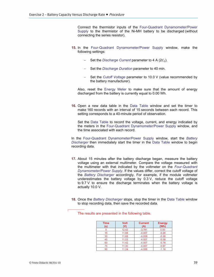
Connect the thermistor inputs of the Four-Quadrant Dynamometer/Power Supply to the thermistor of the Ni-MH battery to be discharged (without connecting the series resistor).

Exercise 2 – Battery Capacity Versus Discharge Rate Procedure
© Festo Didactic 86354-10 35
Figure 19. Ni-MH battery connected to the Four-Quadrant Dynamometer/Power Supply operating as a battery discharger.
Battery voltage and energy supplied during a discharge at 1 5
In this section, you will measure the battery voltage and energy supplied related to a Ni-MH battery during discharge at a rate of 1 . You will use the obtained data to plot a battery discharge curve later in the exercise.
8. In LVDAC-EMS, open the Four-Quadrant Dynamometer/Power Supply window, then make the following settings:
Set the Function parameter to Battery Discharger.
Set the Discharge Current parameter to 2 A (1 ).
Set the Discharge Duration parameter to 70 min.
Set the Cutoff Voltage parameter to 10.0 V (value recommended by the battery manufacturer).
Also, reset the Energy Meter to make sure that the amount of energy discharged from the battery is currently equal to 0.00 Wh.
9. In LVDAC-EMS, open the Data Table window. Set the timer to make 140 records with an interval of 30 seconds between each record. This setting corresponds to a 70-minute period of observation.
Set the Data Table to record the voltage, current, and energy indicated by the meters in the Four-Quadrant Dynamometer/Power Supply window, and the time associated with each record.
*
*
(*) Meter in the Four-Quadrant Dynamometer/Power Supply window of LVDAC-EMS
12 V Ni-MH battery
N
Four-Quadrant Dynamometer/Power Supply

Exercise 2 – Battery Capacity Versus Discharge Rate Procedure
36 © Festo Didactic 86354-10
10. In the Four-Quadrant Dynamometer/Power Supply window, start the Battery Discharger then immediately start the timer in the Data Table window to begin recording data.
11. About 15 minutes after the battery discharge began, measure the battery voltage using an external multimeter. Compare the voltage measured with the multimeter with that indicated by the voltmeter on the Four-Quadrant Dynamometer/Power Supply. If the values differ, correct the cutoff voltage of the Battery Discharger accordingly. For example, if the module voltmeter underestimates the battery voltage by 0.3 V, reduce the cutoff voltage to 9.7 V to ensure the discharge terminates when the battery voltage is actually 10.0 V.
12. Once the Battery Discharger stops, stop the timer in the Data Table window to stop recording data, then save the recorded data.
The results are presented in the following table.
Time (s)
Volt (V)
Current (A)
Energy (Wh)
0 13.15 -1.850 -0.01 30 12.77 -2.008 -0.22 60 12.59 -2.008 -0.44 90 12.49 -2.008 -0.65 120 12.39 -2.008 -0.85 150 12.31 -2.008 -1.06 180 12.24 -2.008 -1.27 210 12.17 -2.008 -1.47 240 12.13 -2.008 -1.67 270 12.10 -2.008 -1.88 300 12.06 -2.008 -2.08 330 12.03 -2.008 -2.28 360 12.02 -2.008 -2.48 390 11.98 -2.008 -2.68 420 11.98 -2.008 -2.88 450 11.98 -2.008 -3.08 480 11.96 -2.008 -3.28 510 11.95 -2.008 -3.48 540 11.94 -2.008 -3.68 570 11.94 -2.008 -3.88 600 11.94 -2.009 -4.08 630 11.94 -2.008 -4.28 660 11.92 -2.008 -4.48 690 11.91 -2.008 -4.68 720 11.91 -2.008 -4.88 750 11.91 -2.008 -5.08 780 11.91 -2.008 -5.28 810 11.91 -2.008 -5.48 840 11.90 -2.007 -5.68 870 11.91 -2.008 -5.88 900 11.90 -2.007 -6.08 930 11.89 -2.008 -6.27 960 11.87 -2.007 -6.47 990 11.87 -2.008 -6.67
1020 11.87 -2.008 -6.87 1050 11.87 -2.008 -7.07 1080 11.87 -2.009 -7.26 1110 11.85 -2.008 -7.46 1140 11.83 -2.008 -7.66 1170 11.83 -2.008 -7.86 1200 11.83 -2.008 -8.06

Exercise 2 – Battery Capacity Versus Discharge Rate Procedure
© Festo Didactic 86354-10 37
Time (s)
Volt (V)
Current (A)
Energy (Wh)
1230 11.83 -2.008 -8.26 1260 11.83 -2.008 -8.45 1290 11.81 -2.007 -8.65 1320 11.81 -2.008 -8.85 1350 11.79 -2.008 -9.05 1380 11.79 -2.008 -9.24 1410 11.80 -2.008 -9.44 1440 11.79 -2.008 -9.64 1470 11.79 -2.009 -9.84 1500 11.78 -2.008 -10.03 1530 11.76 -2.009 -10.23 1560 11.76 -2.008 -10.43 1590 11.76 -2.007 -10.62 1620 11.76 -2.008 -10.82 1650 11.76 -2.007 -11.02 1680 11.74 -2.008 -11.21 1710 11.74 -2.008 -11.41 1740 11.72 -2.008 -11.61 1770 11.72 -2.006 -11.80 1800 11.72 -2.007 -12.00 1830 11.71 -2.007 -12.19 1860 11.68 -2.008 -12.39 1890 11.68 -2.009 -12.59 1920 11.68 -2.008 -12.78 1950 11.68 -2.008 -12.98 1980 11.68 -2.008 -13.17 2010 11.67 -2.008 -13.37 2040 11.65 -2.008 -13.56 2070 11.65 -2.008 -13.76 2100 11.65 -2.008 -13.95 2130 11.62 -2.008 -14.15 2160 11.61 -2.008 -14.34 2190 11.60 -2.008 -14.54 2220 11.60 -2.008 -14.73 2250 11.60 -2.007 -14.92 2280 11.59 -2.007 -15.12 2310 11.57 -2.007 -15.31 2340 11.57 -2.008 -15.51 2370 11.54 -2.008 -15.70 2400 11.53 -2.008 -15.89 2430 11.53 -2.008 -16.09 2460 11.52 -2.008 -16.28 2490 11.50 -2.008 -16.47 2520 11.49 -2.008 -16.66 2550 11.46 -2.007 -16.86 2580 11.45 -2.008 -17.05 2610 11.45 -2.007 -17.24 2640 11.42 -2.008 -17.43 2670 11.40 -2.008 -17.62 2700 11.38 -2.008 -17.81 2730 11.38 -2.008 -18.00 2760 11.34 -2.007 -18.19 2790 11.32 -2.007 -18.38 2820 11.30 -2.008 -18.57 2850 11.30 -2.008 -18.76 2880 11.26 -2.008 -18.95 2910 11.24 -2.007 -19.14 2940 11.23 -2.009 -19.33 2970 11.19 -2.008 -19.51 3000 11.15 -2.008 -19.70 3030 11.11 -2.008 -19.89 3060 11.08 -2.008 -20.07 3090 11.04 -2.008 -20.26 3120 11.00 -2.008 -20.44 3150 10.96 -2.008 -20.62 3180 10.92 -2.008 -20.81 3210 10.87 -2.008 -20.99

Exercise 2 – Battery Capacity Versus Discharge Rate Procedure
38 © Festo Didactic 86354-10
Time (s)
Volt (V)
Current (A)
Energy (Wh)
3240 10.81 -2.007 -21.17 3270 10.75 -2.008 -21.35 3300 10.68 -2.008 -21.53 3330 10.58 -2.008 -21.71 3360 10.51 -2.008 -21.89 3390 10.40 -2.009 -22.06 3420 10.24 -2.008 -22.23 3450 10.09 -2.008 -22.40
End of discharge
Battery voltage versus time at a discharge rate of 1 .
13. Record the duration of the discharge cycle at a rate of 1 .
Discharge duration: min
Discharge duration: 57.5 min (3450 s)
Battery voltage and energy supplied during a discharge at 2 5
In this section, you will measure the battery voltage and energy supplied related to a Ni-MH battery during discharge at a rate of 2 . You will use the obtained data to plot a battery discharge curve later in the exercise.
14. Replace the battery connected to the Four-Quadrant Dynamometer/Power Supply by the other battery (fully charged) of the Ni-MH Batteries module.
9.0
9.5
10.0
10.5
11.0
11.5
12.0
12.5
13.0
13.5
0 5 10 15 20 25 30 35 40 45 50 55 60 65Time (min)
Bat
tery
vol
tage
(V)
Exercise 2 – Battery Capacity Versus Discharge Rate Procedure
© Festo Didactic 86354-10 39
Connect the thermistor inputs of the Four-Quadrant Dynamometer/Power Supply to the thermistor of the Ni-MH battery to be discharged (without connecting the series resistor).
15. In the Four-Quadrant Dynamometer/Power Supply window, make the following settings:
Set the Discharge Current parameter to 4 A (2 ).
Set the Discharge Duration parameter to 40 min.
Set the Cutoff Voltage parameter to 10.0 V (value recommended by the battery manufacturer).
Also, reset the Energy Meter to make sure that the amount of energy discharged from the battery is currently equal to 0.00 Wh.
16. Open a new data table in the Data Table window and set the timer to make 160 records with an interval of 15 seconds between each record. This setting corresponds to a 40-minute period of observation.
Set the Data Table to record the voltage, current, and energy indicated by the meters in the Four-Quadrant Dynamometer/Power Supply window, and the time associated with each record.
In the Four-Quadrant Dynamometer/Power Supply window, start the Battery Discharger then immediately start the timer in the Data Table window to begin recording data.
17. About 15 minutes after the battery discharge began, measure the battery voltage using an external multimeter. Compare the voltage measured with the multimeter with that indicated by the voltmeter on the Four-Quadrant Dynamometer/Power Supply. If the values differ, correct the cutoff voltage of the Battery Discharger accordingly. For example, if the module voltmeter underestimates the battery voltage by 0.3 V, reduce the cutoff voltage to 9.7 V to ensure the discharge terminates when the battery voltage is actually 10.0 V.
18. Once the Battery Discharger stops, stop the timer in the Data Table window to stop recording data, then save the recorded data.
The results are presented in the following table.
Time (s)
Volt (V)
Current (A)
Energy (Wh)
0 12.42 -3.781 0.00 15 11.88 -4.007 -0.20 30 11.68 -4.008 -0.39 45 11.53 -4.007 -0.59 60 11.42 -4.007 -0.78 75 11.30 -4.007 -0.97 90 11.24 -4.006 -1.16

Exercise 2 – Battery Capacity Versus Discharge Rate Procedure
40 © Festo Didactic 86354-10
Time (s)
Volt (V)
Current (A)
Energy (Wh)
105 11.15 -4.005 -1.34 120 11.11 -4.006 -1.53 135 11.08 -4.001 -1.72 150 11.02 -4.008 -1.90 165 11.00 -4.005 -2.08 180 10.97 -4.007 -2.27 195 10.95 -4.010 -2.45 210 10.96 -4.006 -2.63 225 10.94 -4.006 -2.82 240 10.94 -4.006 -3.00 255 10.94 -4.008 -3.18 270 10.92 -4.009 -3.36 285 10.92 -4.004 -3.55 300 10.93 -4.004 -3.73 315 10.92 -4.006 -3.91 330 10.92 -4.002 -4.09 345 10.92 -4.005 -4.28 360 10.92 -4.004 -4.46 375 10.92 -4.006 -4.64 390 10.92 -4.006 -4.82 405 10.91 -4.009 -5.00 420 10.92 -4.007 -5.19 435 10.91 -4.006 -5.37 450 10.92 -4.009 -5.55 465 10.92 -4.005 -5.73 480 10.89 -4.009 -5.92 495 10.91 -4.006 -6.10 510 10.89 -4.005 -6.28 525 10.91 -4.006 -6.46 540 10.89 -4.008 -6.64 555 10.89 -4.003 -6.82 570 10.89 -4.009 -7.01 585 10.87 -4.006 -7.19 600 10.85 -4.007 -7.37 615 10.85 -4.006 -7.55 630 10.85 -4.006 -7.73 645 10.87 -4.008 -7.91 660 10.85 -4.005 -8.09 675 10.85 -4.007 -8.28 690 10.83 -4.007 -8.46 705 10.82 -4.007 -8.64 720 10.81 -4.007 -8.82 735 10.81 -4.005 -9.00 750 10.82 -4.005 -9.18 765 10.81 -4.008 -9.36 780 10.81 -4.008 -9.54 795 10.81 -4.005 -9.72 810 10.77 -4.008 -9.90 825 10.77 -4.006 -10.08 840 10.77 -4.006 -10.26 855 10.77 -4.006 -10.44 870 10.76 -4.007 -10.62 885 10.75 -4.006 -10.80 900 10.74 -4.007 -10.98 915 10.74 -4.007 -11.16 930 10.74 -4.008 -11.34 945 10.74 -4.005 -11.52 960 10.74 -4.008 -11.70 975 10.70 -4.006 -11.87 990 10.70 -4.007 -12.05
1005 10.70 -4.007 -12.23 1020 10.70 -4.006 -12.41 1035 10.70 -4.007 -12.59 1050 10.68 -4.007 -12.77 1065 10.66 -4.007 -12.95 1080 10.65 -4.005 -13.12 1095 10.63 -4.007 -13.30

Exercise 2 – Battery Capacity Versus Discharge Rate Procedure
© Festo Didactic 86354-10 41
Time (s)
Volt (V)
Current (A)
Energy (Wh)
1110 10.62 -4.007 -13.48 1125 10.62 -4.007 -13.66 1140 10.62 -4.006 -13.83 1155 10.62 -4.007 -14.01 1170 10.58 -4.006 -14.19 1185 10.59 -4.007 -14.36 1200 10.58 -4.007 -14.54 1215 10.56 -4.007 -14.72 1230 10.55 -4.006 -14.89 1245 10.54 -4.006 -15.07 1260 10.53 -4.008 -15.25 1275 10.51 -4.006 -15.42 1290 10.51 -4.008 -15.60 1305 10.48 -4.006 -15.77 1320 10.47 -4.007 -15.95 1335 10.45 -4.006 -16.12 1350 10.43 -4.007 -16.30 1365 10.43 -4.006 -16.47 1380 10.41 -4.007 -16.64 1395 10.39 -4.007 -16.82 1410 10.36 -4.007 -16.99 1425 10.34 -4.006 -17.16 1440 10.32 -4.006 -17.34 1455 10.28 -4.007 -17.51 1470 10.28 -4.007 -17.68 1485 10.24 -4.006 -17.85 1500 10.21 -4.006 -18.02 1515 10.19 -4.007 -18.19 1530 10.17 -4.006 -18.36 1545 10.11 -4.007 -18.53 1560 10.09 -4.006 -18.70 1575 10.06 -4.007 -18.87 1590 9.98 -4.006 -19.04
End of discharge
Battery voltage versus time at a discharge rate of 2 .
9.0
9.5
10.0
10.5
11.0
11.5
12.0
12.5
13.0
0 5 10 15 20 25 30Time (min)
Bat
tery
vol
tage
(V)
Exercise 2 – Battery Capacity Versus Discharge Rate Procedure
42 © Festo Didactic 86354-10
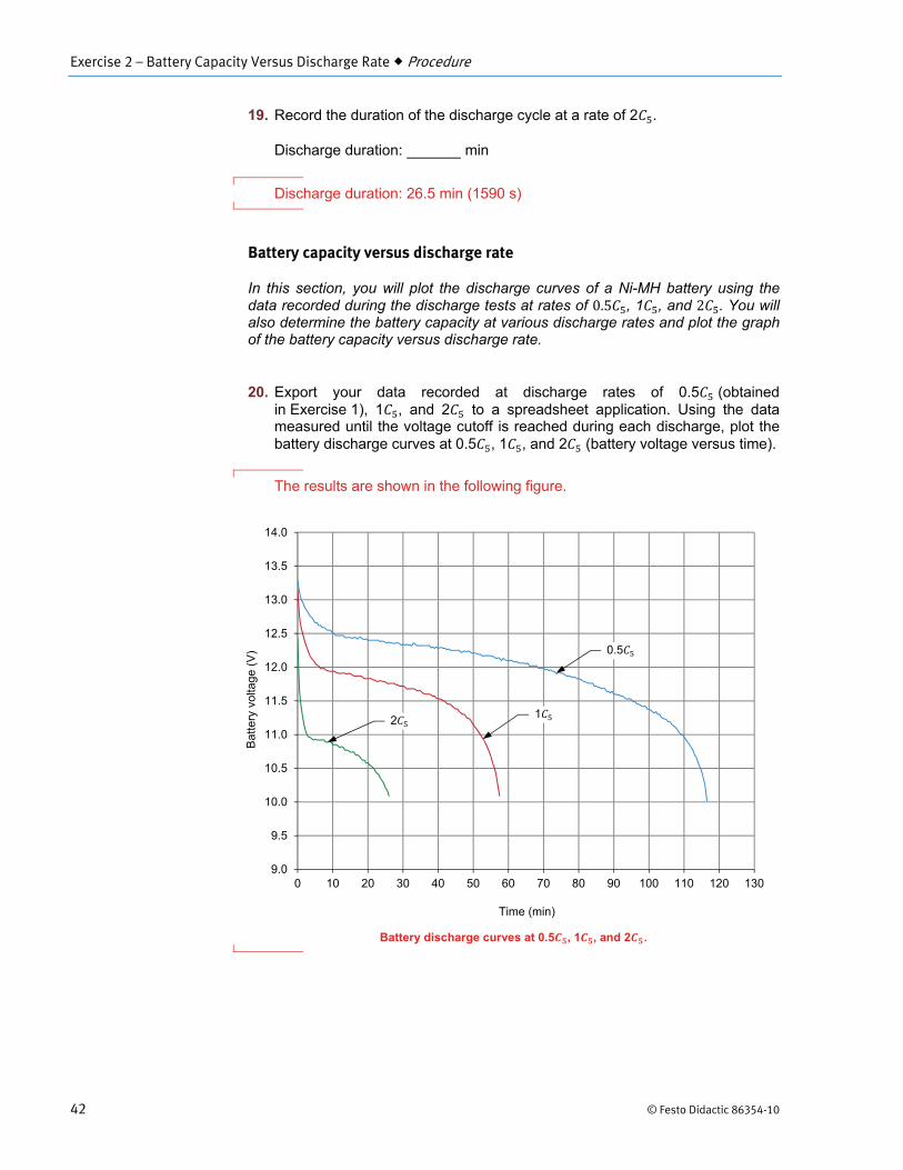
19. Record the duration of the discharge cycle at a rate of 2 .
Discharge duration: min
Discharge duration: 26.5 min (1590 s)
Battery capacity versus discharge rate
In this section, you will plot the discharge curves of a Ni-MH battery using the data recorded during the discharge tests at rates of , 1 , and . You will also determine the battery capacity at various discharge rates and plot the graph of the battery capacity versus discharge rate.
20. Export your data recorded at discharge rates of 0.5 (obtained in Exercise 1), 1 , and 2 to a spreadsheet application. Using the data measured until the voltage cutoff is reached during each discharge, plot the battery discharge curves at 0.5 , 1 , and 2 (battery voltage versus time).
The results are shown in the following figure.
Battery discharge curves at 0.5 , 1 , and 2 .
9.0
9.5
10.0
10.5
11.0
11.5
12.0
12.5
13.0
13.5
14.0
0 10 20 30 40 50 60 70 80 90 100 110 120 130
Time (min)
Bat
tery
vol
tage
(V) 0.5
1 2

Exercise 2 – Battery Capacity Versus Discharge Rate Procedure
© Festo Didactic 86354-10 43
21. From the curves you plotted in the previous step, determine the discharge time to the specified cutoff voltage, expressed in hours, for each discharge rate (0.5 , 1 , and ). Record your results in the appropriate cells of Table 4.
a The discharge time, capacity in Ah, and capacity in % for a discharge rate of 0.2 are already provided in Table 4.
22. Calculate the capacity of the battery at , 1 , and from the curves you plotted in the previous step. Use the following suggested equation: capacity discharge current discharge time to the specified cutoff voltage. Record your results (expressed in Ah) in the appropriate cells of Table 4.
23. Express your calculated capacity values as a percentage of the nominal capacity of the battery. Record your results in the appropriate cells of Table 4.
Table 4. Capacity and discharge time of a Ni-MH battery in relation to the discharge current.
Discharge rate
Discharge current
(A)
Discharge time (min)
Capacity (Ah)
Capacity (%)
0.2 0.40 305 2.03 102
0.5 1.00
1 2.00
2 4.00
The results are presented in the following table.
Capacity and discharge time of a Ni-MH battery in relation to the discharge current.
Discharge rate
Discharge current
(A)
Discharge time (min)
Capacity (Ah)
Capacity (%)
0.2 0.40 305 2.03 102
0.5 1.00 117 1.94 97.0
1 2.00 57.5 1.92 96.0
2 4.00 26.5 1.77 88.5
Exercise 2 – Battery Capacity Versus Discharge Rate Procedure
44 © Festo Didactic 86354-10
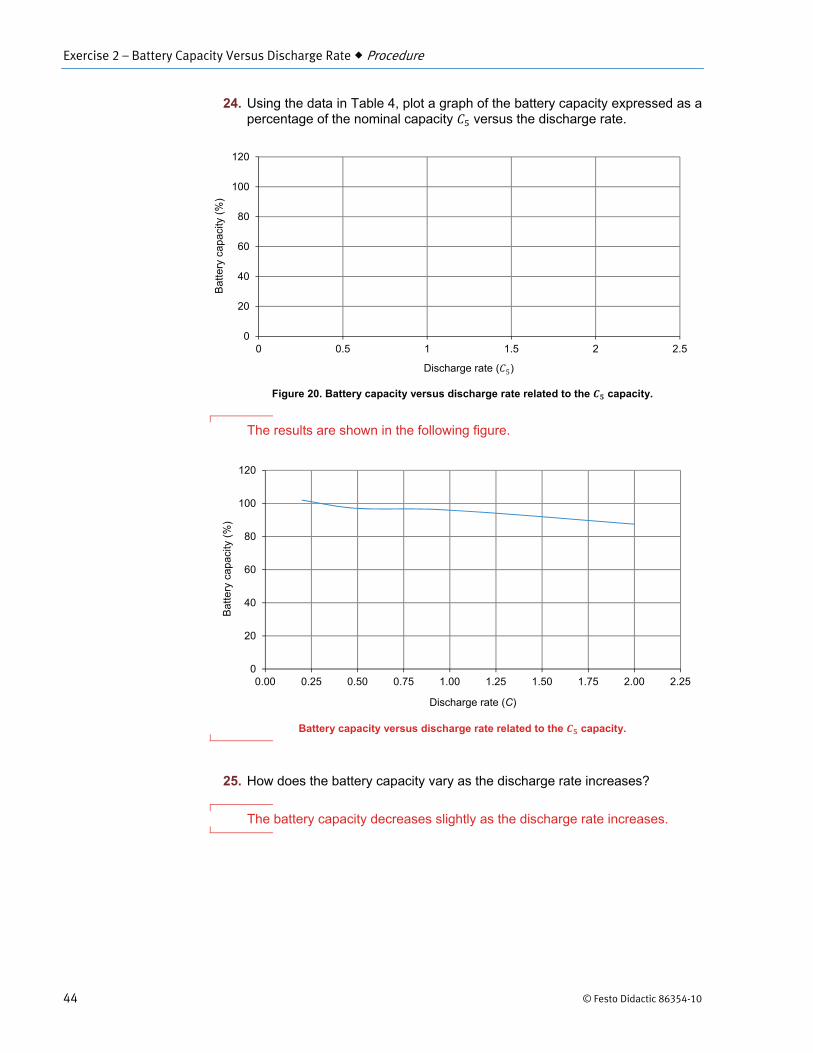
24. Using the data in Table 4, plot a graph of the battery capacity expressed as a percentage of the nominal capacity versus the discharge rate.
Figure 20. Battery capacity versus discharge rate related to the capacity.
The results are shown in the following figure.
Battery capacity versus discharge rate related to the capacity.
25. How does the battery capacity vary as the discharge rate increases?
The battery capacity decreases slightly as the discharge rate increases.
0
20
40
60
80
100
120
0 0.5 1 1.5 2 2.5
0
20
40
60
80
100
120
0.00 0.25 0.50 0.75 1.00 1.25 1.50 1.75 2.00 2.25
Discharge rate ( )
Bat
tery
cap
acity
(%)
Discharge rate (C)
Bat
tery
cap
acity
(%)

Exercise 2 – Battery Capacity Versus Discharge Rate Procedure
© Festo Didactic 86354-10 45
Specific energy and energy density
In this section, you will determine the specific energy and energy density of the Ni-MH batteries. You will then observe how the specific energy and energy density related to the Ni-MH batteries vary with the discharge rate.
26. Record the amount of energy supplied (in Wh) for each discharge rate (0.5 , 1 , and 2 ) in the second column of Table 5. Then, calculate the specific energy of the Ni-MH batteries for each discharge rate using the measured released energy values, and record your results in the third column of Table 5. Assume that the weight of each battery in the Ni-MH Batteries module is 0.285 kg (0.628 lb).
Calculate the energy density of the Ni-MH batteries for each discharge rate (0.5 , 1 , and 2 ) using the measured released energy values, and record your results in the fourth column of Table 5. Assume that the volume of each battery in the Ni-MH Batteries module is 0.0762 L (4.65 in3).
Table 5. Specific energy and energy density of the Ni-MH batteries at discharge rates of 0.5 , 1 , and 2 .
Discharge rate Released energy (Wh)
Specific energy (Wh/kg or Wh/lb)
Energy density (Wh/L or Wh/in3)
0.5
1
2
The results are presented in the following tables.
Specific energy and energy density of the Ni-MH batteries at discharge rates of 0.5 , 1 , and 2 .
Discharge rate Released energy (Wh)
Specific energy [Wh/kg (Wh/lb)]
Energy density [Wh/L (Wh/in3)]
0.5 23.4 82.1 (37.3) 307 (5.03)
1 22.4 78.6 (35.7) 294 (4.82)
2 19.0 66.7 (30.3) 249 (4.09)
27. How do the specific energy and energy density vary when the discharge rate increases?
Both the specific energy and energy density decrease slightly as the discharge rate increases.
28. Close LVDAC-EMS, then turn off all the equipment. Disconnect all leads and return them to their storage location.

Exercise 2 – Battery Capacity Versus Discharge Rate Conclusion
46 © Festo Didactic 86354-10
In this exercise, you became familiar with the effects of the discharge rate and battery temperature on the capacity and voltage of a Ni-MH battery. You learned how to calculate the energy supplied during a discharge cycle. You also learned what the specific energy and the energy density of a battery are, and how to determine these two parameters.
1. When a Ni-MH battery discharges at a high current rate (1 and more), what happens to the voltage measured across the battery and to its relative battery capacity?
The higher the current rate, the lower the measured voltage across the battery. Similarly, the higher the current rate, the less available relative battery capacity during the discharge cycle.
2. What is the effect of ambient temperature on the relative capacity of a Ni-MH battery at low discharge rates (about 0.2 )? At high discharge rates (about 3 )?
At low discharge rates, ambient temperature does not significantly reduce the relative capacity of a Ni-MH battery, even at very low temperatures (-20°C or -4°F). When discharging a Ni-MH battery at high current rates, however, the relative battery capacity begins to drop rapidly when the ambient temperature falls below 10°C (50°F).
3. What is the memory effect and how is it possible to cancel its effect?
The memory effect is a reversible drop in battery voltage that may occur when a battery is repetitively partially discharged and recharged. It is possible to cancel its effect by making the battery go through successive full discharge cycles.
4. Suppose a Ni-MH battery having a capacity of 15 Ah is discharged at a rate of 0.2 , i.e., a constant current of 3 A. Also suppose that the average voltage during the discharge is 10 V. Calculate the amount of energy supplied by the battery during the complete discharge cycle of 5 hours.
The average power the battery delivers is equal to: 10 V 3 A 30 W. The energy supplied by the battery during the complete discharge cycle of 5 hours is thus equal to: 30 W 5 h 150 Wh.
CONCLUSION
REVIEW QUESTIONS
Exercise 2 – Battery Capacity Versus Discharge Rate Review Questions
© Festo Didactic 86354-10 47
5. Suppose that a 12 V Ni-MH battery releases a total of 12 Wh during a full-discharge cycle. If it has a weight of 0.18 kg (0.40 lb) and a volume of 0.05 L (3.05 in3), what are its specific energy and energy density?
The specific energy of the battery is 66.7 Wh/kg (12 Wh 0.18 kg) or 30 Wh/lb (12 Wh 0.40 lb). The energy density of the battery is 240 Wh/L (12 Wh 0.05 L) or 3.93 Wh/in3 (12 Wh 3.05 in3).


© Festo Didactic 86354-10 133
Bibliography
Linden, David, and Reddy, Thomas B., Handbook of Batteries, 3d ed. New York: McGraw-Hill, 2002, ISBN 0-07-135978-8.