Embed Size (px)
Citation preview

Electrically controlled HTSC/ferroelectric coplanar waveguide
S.S. Gevorgian D.I. Kaparkov O.G. Vendik
Indexing terms: Superconducting microwave devices, Ferroelectrics
Abstract: It is shown that in an integrated YBa,Cu,O,SrTiO, structure coplanar waveguide (CPW) electrical control of microwave propaga- tion characteristics is possible. Microwave losses of less than 0.2 dB/cm at 10 GHz can be achieved at liquid nitrogen temperatures, provided ferro- electric films with perfect crystalline structures are used. Electrically controlled changes in effective dielectric permittivity of more than 40% are pre- dicted at 77 K and 10 GHz. Sections of these CPWs can be used in electrically controlled phase shifters and resonators.
1 Introduction
Electrically controlled nonlinear ferroelectric microwave components have been studied in the past. Microwave applications of ferroelectric thin films have been limited by high insertion loss [l]. Recent progress in HTSC tech- nology, improvement of dielectric properties of SrTiO, thin films, and their integration with HTSC films as buffer layers [2], makes possible the development of elec- trically controlled YBa,Cu,O,SrTiO, based microwave devices. In this letter we present the electrically controlled microwave performance of a YBa,Cu,O,/SrTiO, CPW structure see Fig. 1. The phenomenological theory of fer- roelectrics and HTSC, dong with conformal mapping
2s - 1 - ’ d HTSC
9
hl
E 2 I substrate h 2 1 I Fig. 1 Cross section of C P W
techniques, are used to model the electrically controlled microwave propagation in such CPWs.
2
The dielectric properties of ferroelectric crystals are complex functions of temperature and applied electric
Dielectric properties of the ferroelectrics
0 IEE, 1994 Paper 1444H (Ell), first received 9th March and in revised form 6th July 1994 The authors are with the Department of Microwave Technology, Chal- mers University of Technology, S-412 96 Goteborg, Sweden
IEE Proc.-Microw. Antennas Propag., Vol. 141, No. 6, December 1994
field. First, we study the performance of ferroelectrics at cryogenic temperatures, to see what can be expected in the sense of electrically induced dielectric permittivity change and microwave losses. For the dielectric permit- tivity and loss tangent of a ferroelectric crystal a phenom- enological model [3] is used. External electric field, E, and temperature, T , dependence of the relative dielectric permittivity is given by
(1) &(E, 7-1 = E O 0 / W > T ) where
W E , T ) = [ ( tz + tw2 + t12/3 + c(t2 + V 3 p 2 - n 2 j 3 - rl
t = + ~ ~ I l 1 ” g = (0/T,)[1/16 + (T/O)’l1/’ - 1
E, is the rationing field [3], 0 is the Debye temperature of the crystal sub-lattice, &, is the rate of the crystal strain, which is used as a fitting parameter where actual ferroelectric films with defects are concerned. The fre- quency dispersion of &(E, T) is small and can be ignored up to 150-200 GHz. Frequency, field and temperature dependence of the dielectric loss tangent is given by
tan 6 = (n/8Mo,,/oM)’(o/o..Xtt + 1)’/@@, 7‘) (2) This formula was derived for the case of scattering of the ferroelectric oscillation mode by thermal phonons in the perfect ferroelectric crystal. In real materials, the piesoelectric conversion of the microwave field energy due to charged defects can increase the actual value of tan 6. A linear dependence of tan 6 upon microwave fre- quency follows from eqn. 2.
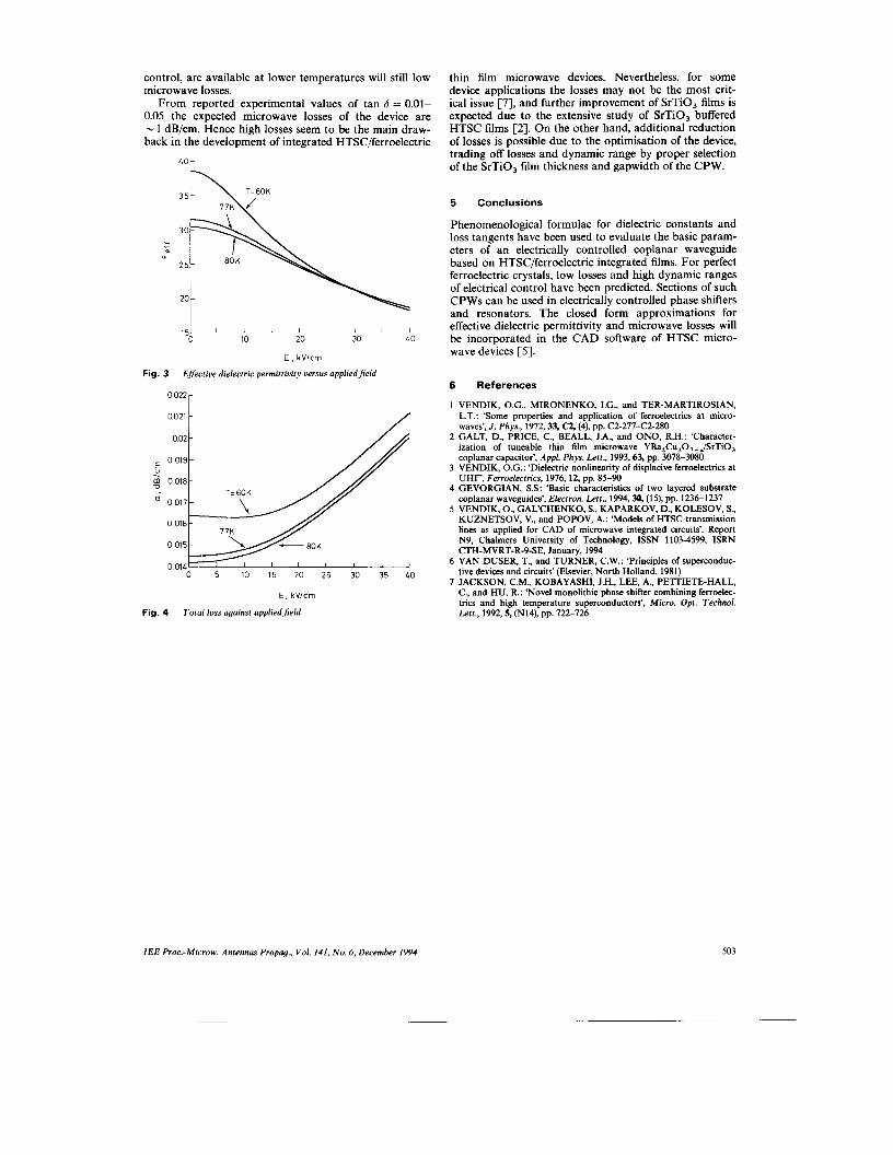
Characteristics parameters for a single crystal of SrTiO, are [SI: T. = 37 K, 0 = 160 K, E, = 12 kV/cm, E,, = 2000, o,, = 6.7 x 10” s-’, mM = 2.6 x lo1, s-’. For these data the dependence of the dielectric permit- tivity and tan 6 upon temperature is shown in Figs. 2A and 2B. In calculations, = 0.7 has been set to fit our results those given in Reference 1. The insert in Fig. 2A shows the results of experimental observation for a 5 pm gap in a microstrip resonator on top of a 0.55 pm thick SrTiO, film [l]. High experimental values of tan 6 reported in the literature (tan 6 < 0.05 at 4 K and
The support of Prof. E. Kollberg is greatly acknowledged. Thanks are also addressed to Prof. A. Herman for helpful discussions. This work was supported by the Swedish National Board of Industrial and Technical Development.
501
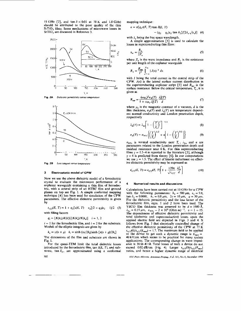
11 GHz [2], and tan 6 < 0.01 at 78 K and 1.8 GHz) should be attributed to the poor quality of the thin SrTiO, films. Some mechanisms of microwave losses in SrTiO, are discussed in Reference 3.
2500r 1 - - - 7 2400
1600
800
I O O V
0 50 100 150 200 250 3W T. K
200 v
01 I I I 1 I I 0 50 100 150 200 250 300
T. K
Fig. 2A Dielectric permittivity versus temperature
0 7r
0 50 100 150 200 250 300
T. K
Fig. 2B Loss tangent urnsus temperature
3 Electrostatic model of CPW
Now we use the above dielectric model of a ferroelectric crystal to evaluate the microwave performance of a coplanar waveguide containing a thin film of ferroelec- tric, with a central strip of an HTSC film and ground planes on top see Fig. 1. A simple conformal mapping technique [4] has been used for simulation of the CPW parameters. The effective dielectric permittivity is given by
%q/I(E, T ) = 1 i- qi[&(E, T ) - %1/2 + q z k z - l)/2 (3) with filling factors
qi = ( K ( k , ) / K ( k : . ) ) ( K ( k b ) / K o ) i = 1, 2 i = 1 for the ferroelectric film, and i = 2 for the substrate. Moduli of the elliptic integrals are given by
k, = s/(s + g) ki = sinh (ns/2hi)/sinh [n(s + g)/2hi] The dimensions of the film and substrate are shown in Fig. 1.
For the quasi-TEM limit the total dielectric losses introduced by the ferroelectric film, tan 6(E, T), and sub- strate, tan 6 , , are approximated using a conformal
502
mapping technique :
a = x[q,E(E, T) tan 6(E, T)
with I, being the free space wavelength.
losses in superconducting thin films: A simple approximation [5] is used to calculate the
Rl ase = X T
‘ L o
where 2, is the wave impedance and R, is the resistance per unit length of the coplanar waveguide
with I being the total current in the central strip of the CPW. J(x ) is the lateral surface current distribution in the superconducting coplanar strips [5] and R,, is the surface resistance. Below the critical temperature, T, , it is given as
(7)
where po is the magnetic constant of a vacuum, d is the film thickness, odT) and &(T) are temperature depend- ent normal conductivity and London penetration depth, respectively
uNTc is normal conductivity near T, , I, and a are parameters related to the London penetration depth and residual resistance near 0 K. For thin superconducting films y = 1.5-4 is reported in the literature [SI, although y = 4 is predicted from theory [6] . In our computations we use y = 1.5. The effect of kinetic inductance on effect- ive dielectric permittivity may be expressed as
4 Numerical results and discussions
Calculations have been carried out at 10 GHz for a CPW with the following parameters: h, = 500 pm, E, = 9.8, tan 6, = O.OOO1, h, = 0.8 pm, 2s = 10 pm, g = 50 pm. For the dielectric permittivity and the loss factor of the ferroelectric film, eqns. 1 and 2 have been used. The YBCO film thickness was assumed to be d = 1OOO A, ALo = 0.15 pm, uNTe = 2 x lo6 (Ohm m)-’, a = 1 -+ 15. The dependences of effective dielectric permittivity and total (dielectric and superconductive) losses upon the applied electric field are depicted in Figs. 3 and 4. It follows from Fig. 3 that electrically controlled change of the effective dielectric permittivity of the CPW at 77 K E , ~ , ( O ) / E , ~ ~ ( E ~ ~ ) = 1.7. The maximum field to be applied to the device to get such a dynamic range is E,, = 40 kV/cm which seems to be practical for many system applications. The corresponding change in wave imped- ance is 36 0-41 R. Total losses of such a device do not exceed 0.02 dB/m (Fig. 4). Larger ee,,(0)/ee,,(EMx) ratios, and hence a higher dynamic range of electrical
1EE Proc.-Microw. Antennas Propog., Vol. 141, No. 6 , December I994
control, are available at lower temperatures will still low microwave losses.
From reported experimental values of tan 6 = 0.01- 0.05 the expected microwave losses of the device are - 1 dB/cm. Hence high losses seem to be the main draw- back in the development of integrated HTSC/ferroelectric
20 -
I I I I I 1 I 10 20 30 40
l S L 0
E , kVlcm
Fig. 3 Efective dielectric permittivity versus appliedfield
/ 0021 1 002 -
m 0018-
I I 1 0 5 10 15 20 25 30 35 40
E. kVIcm
Fig. 4 Total loss against appliedfield
thin film microwave devices. Nevertheless, for some device applications the losses may not be the most crit- ical issue [7], and further improvement of SrTiO, films is expected due to the extensive study of SrTiO, buffered HTSC films [2]. On the other hand, additional reduction of losses is possible due to the optimisation of the device, trading off losses and dynamic range by proper selection of the SrTiO, film thickness and gapwidth of the CPW.
5 Conclusions
Phenomenological formulae for dielectric constants and loss tangents have been used to evaluate the basic param- eters of an electrically controlled coplanar waveguide based on HTSC/ferroelectric integrated films. For perfect ferroelectric crystals, low losses and high dynamic ranges of electrical control have been predicted. Sections of such CPWs can be used in electrically controlled phase shifters and resonators. The closed form approximations for effective dielectric permittivity and microwave losses will be incorporated in the CAD software of HTSC micro- wave devices [ 5 ] .
6 References
1 VENDIK, O.G., MIRONENKO, I.G., and TER-MARTIROSIAN, L.T.: ‘Some properties and application of ferroelectrics at micro- waves’, J. Phys., 1972,33, CZ, (4), pp. C2-27742-280
2 GALT, D., PRICE, C., BEALL, J.A., and ONO, R.H.: ‘Character- ization of tuneable thin film microwave YBa,Cu,O,_JSrTiO, coplanar capacitor’, Appl. Phys. Lett., 1993,63, pp. 3078-3080
3 VENDIK, O.G.: ‘Dielectric nonlinearity of displacive ferroelectrics at UHF‘, Ferroelectrics, 1976, 12, pp. 85-90
4 GEVORGIAN, S S : ‘Basic characteristics of two layered substrate coplanar waveguides’, Electron. Lett., 1994,30, (15), pp. 1236-1237
5 VENDIK, O., GAL‘CHENKO, S., KAPARKOV, D., KOLESOV, S., KUZNETSOV, V., and POPOV, A.: ‘Models of HTSC transmission lines as applied for CAD of microwave integrated circuits’. Report N9, Chalmers University of Technology, ISSN 1103-4599, ISRN CTH-MVRT-R-9-SE. January, 1994
6 VAN DUSER, T., and TURNER, C.W.: ‘Principles of superconduc- tive devices and circuits’ (Elsevier, North Holland, 1981)
7 JACKSON, C.M., KOBAYASHI, J.H., LEE, A., PETTIETE-HALL, C., and HU, R.: ‘Novel monolithic phase shifter combining ferroelec- trics and high temperature superconductors’, Micro. Opt. Technol. Lett., 1992,5, (N14), pp. 722-726
IEE Proc.-Microw. Antennas Propag., Vol. 141, No. 6 , December 1994 503


![FERROELECTRIC RAM [FRAM]](https://img.pdfslide.us/doc/110x75/56816799550346895ddcd567/ferroelectric-ram-fram.jpg)


