Embed Size (px)
Citation preview

1 www.megger.com Megger ELECTRICAL TESTER October 2013
The industry’s recognised information tool
Published by Megger October 2013
CIRED - Knights of the round tableAndrea Bonetti – STRI AB – Västerås Sweden
Dr. Murari Saha – ABB AB – Västerås Sweden
CIRED brought ABB, Siemens, EDF, STRI, Megger and other major players together to discuss new protection schemes for decentralised generation. Pictures: courtesy of Dr. Lothar Fickert
CIRED – ELECTRICITY DISTRIBUTION SYSTEMS FOR A SUSTAINABLE FUTURE
CIRED, the major International Electricity Conference and Exhibition, is the leading forum where the electricity distribution community meets every two years in various European venues, with a worldwide perspective and participation. The 2013 CIRED Conference is the 22nd in the series and took place between 10th and 13th June in Stockholm, at the Kista-fair in Kista.
Fourteen round tables were organized for this event. Murari Saha (ABB AB) and Andrea Bonetti (Megger Sweden AB), both of whom are Swedish representatives of the IEC Standardization Committee on Smart Grid, were invited to be part of the speaker panel for Round Table 3 (RT3), addressing relay protection challenges under the title of “New protection schemes for grids with decentralized generation”.
The scope of RT3 was set by this statement: Decentralized generation in distribution grids is becoming more and more important and requires new strategies and functions for grid and generation protection. This is a challenge for grid protection in MV grids as well as in LV grids and it calls for adaption strategies and new protection schemes. Therefore, new performance of protection equipment in MV and LV grids with or without communication will be addressed. The round table will give an overview of the current state of the art in decentralized protection, and also a glimpse into the future.
The convener of RT3 was Dr Lothar Fickert, from the Technical University of Graz, Austria. The speaker panel comprised Prof Dr Siegfried Lemmer, SIEMENS AG, Germany; Dr Alexander Apostolov, OMICRON, USA; Laurent Karsenti, EDF, France; Andrea Bonetti, Megger Sweden AB, Sweden; and Dr Murari Saha, ABB, Sweden. Approximately 150 people participated in the Round Table (RT3) session, illustrating the wide interest in protection problems relating to the new “power system” created by distributed generation.
This short article is a report of the main concepts that were raised by the speakers and the main questions that were posed by the audience.
Each of the panellists gave a presentation as an introduction to the discussion. The topics of these introductions were:
�New protection schemes for grids with decentralized generation (Dr Siegfried Lemmer)
� New protection schemes for grids with DERs (Dr Alexander Apostolov)
� Protection schemes: distributed generation impact – 50.2 Hz issue – unsolicited islanding (Laurent Karsenti)
� Use of the IEC 61850 standard in smart grid protection schemes to increase the security of the protection system (Andrea Bonetti)
� Smart grid protection – a manufacturer’s perspective (Dr Murari Mohan Saha)
SHORT NOTES FROM THE PANEL SESSION DISCUSSIONS
Dr Lothar FickertIn his introductory presentation, Dr Fickert made two particularly significant points:
� As protection is a very sensitive and difficult subject, there is a need to do a lot of education at all levels, from universities to the organizations. There is the risk that inexperience in protection could result in complicated schemes that may reduce the efficiency of the protection system.
� As the smart grid MV networks appear to be more meshed than radial, we may need to draw inspiration from HV network protection competence, where there is long-established experience. Can we get inspiration from HV network experience?
Dr Sigfried LemmerDr Lemmer emphasised one of the major objectives of relay protection: the capability to protect the power system. This means that if the primary system changes, we need to reflect these changes in what is commonly called the secondary system.
Some important changes in the power system are current in-feeds at new locations that were not present when the protection system was designed, and different transient behaviour of the in-feeds during power system faults. From the system protection point of view, some consequences of these new factors in the power network are:
Sympathetic tripping (unwanted trip) � Relays that use non-directional fault
detection, which are typical in MV radial networks, are “fooled” by short circuit currents coming from another direction. Different fault detection algorithms, including additional measurement quantities, should be considered (directional overcurrent relays for instance).
Blinding (due to external fault current in-feed)
� This phenomenon, which is due to additional fault current not seen by the protection relay, may require settings changes in some protection relays.
Presence of negative sequence components in the faulty electrical quantities
� This phenomenon has to do with the different transient behaviour of the new infeeds: the injection of negative sequence system from the inverters. This phenomenon is new and does not happen with conventional mechanical generators.
Dr Alex ApostolovDr Apostolov explained that considering the situation from point of view of testing, we
need to ensure that the protection systems are properly tested, but when you test something you need to know how it works.
The short-circuit transient from inverters is just 2 or 3 ms long, which is very different from the behaviour we are familiar with (mechanical inertia of generators). One hypothesis is that new protection relays may need to be able to recognize such transients.
From the testing point of view, we will see more and more need for system tests – for example, end-to-end testing – and we will increasingly see the need to test remote units linked by communication that must also be included in the testing.
Considering IEC 61850, we are already seeing the meaning of SCL changing from Substation Configuration Language to System Configuration Language. This is a sign that at IEC 61850 level there is also a need to take a wider view of the power system, which has impact on communication requirements. From the technical point of view we are seeing a wider approach in communication: Wide Area Network GOOSE messages. These can be used over any type of communication including, for example, UDP Multicast.
Laurent KarsentiLaurent Karsenti brought examples from EDF experience, and pointed out the problem of islanding detection, mentioning the so-called “50.2 Hz Issue”. This applies specifically to France, but there are similar issues in other European countries:
�Germany, 13 GW of distributed generation, disconnecting at f > 50.2 Hz
� Italy, 12 GW of distributed generation, disconnecting at f > 50.3 Hz
� France, 1 GW of distributed generation, disconnecting at f > 50.2 Hz
At the present time, there is no recognized method to detect islanding. The idea is to isolate the DG generators, but not all at the
same time. One of the main Smart Grid issues is not to disconnect on the basis of frequency, and to try to keep the DG connected, possibly with help of (smart) load shedding.
Andrea BonettiAndrea Bonetti said that some of the new phenomena in MV networks are well known, although sometimes for different reasons, to the HV protection community.
Weakened in-feed is an HV power system fault situation that well describes the fact that DGs tend not to contribute to the fault current for a sufficient period of time to allow the relay to detect the power system fault. Weakened in-feed protection communication schemes offer some proven solutions for reliable fault clearance.
With all of the doubts about how to handle the new protection system, it comes as good news that the use of IEC 61850 GOOSE messages to implement protection schemes is able to provide higher security than the use of the conventional technology. This is because the GOOSE technology allows the implementation of communication supervision on the receiving relay (IED), which can take a local decision on what to do (setting change) when a communication failure is detected.
Dr Murari SahaDr Saha discussed how changes power system topologies will require changes in protection strategies. It is very probable that in the short term we will see more and more differential protection schemes in Smart Grids; they are well consolidated and the community has several years of experience in their development, commissioning, operation and maintenance.
Despite the need for competence in communication issues, it is still very important to remember that communication is at the service of the protection system, and not vice-versa. We need more power system engineers to be able to specify the correct requirements
continued on page 2
Remote control revealed,page 7
ELECTRICALTESTER
Acoustic pinpointing progress, page 5
High voltage vexation, page 2

2 Megger ELECTRICAL TESTER October 2013 www.megger.com
Wrestling simultaneously with concerns that include the ongoing paucity of funds for investment, ageing and even life-expired plant, and an increasing shortage of skilled engineers and technicians, the electricity supply industry is under pressure as never before. There’s every reason to believe the pressure will increase rather than decrease in the coming years. Let’s take a closer look.
The shortage of funds for investment has any number of roots. The recession is certainly one, as is the pressure from the shareholders of power companies for returns that are at least steady and preferably increasing even though market conditions are difficult. The need to shut down existing generating capacity to meet environmental requirements and as a result, to invest in new power stations is another major issue that’s diverting budget away from routine plant maintenance and replacement.
With these factors in mind, we should be under no illusion that funds – except for those allocated to specific projects, like the construction of the proposed new nuclear power station at Hinckley Point in the UK – will be more readily available in future. They won’t, and the power industry must find ways to cope with this protracted dearth of cash.
The industry’s cash problems are compounded by the age of much of the plant currently in use, which is either close to or beyond its design life. This applies not only to capital items – power transformers, circuit breakers and the like – but also to cables and, in particular, to
underground cables where aging is a serious concern and locating faults is difficult.
Finally, to make life even more challenging for companies in the power sector, there are financial penalties in place for customer supply interruptions and customer minutes lost. In summary, there are all the ingredients of a perfect storm – lack of money to buy new plant, old plant that’s prone to age-related failure, and tough penalties if anything does go wrong!
What’s to be done?
There’s no complete solution, of course, but a strategy that’s proving very useful is asset optimisation. In simple terms, this means maintaining and where necessary, repairing assets to the highest standard that’s possible and affordable, and then putting those assets to the best use. The key to success, particularly with older assets, is accurately determining their current condition and this depends on effective testing.
Fortunately, in recent years much progress has been made in the design of test equipment for power plant. New methods of testing power transformers using sweep frequency response analysis (SFRA) allow potential problems to be identified without the need to dismantle the transformer, as would previously have been necessary. Similar progress has been made in circuit breaker test sets, which now allow the condition of the contacts and mechanical components to be conveniently and accurately assessed without disassembly.
And in the field of underground cable testing, the latest techniques allow insulation condition to be reliably determined. When faults do occur, they allow the precise location to be determined, so that remedial action can be taken quickly and with a minimum amount of excavation.
Across the board, the new generation of power test equipment yields its largest benefits when it is used for condition assessment and the detection of incipient faults, as the knowledge gained from accurate and dependable test results makes truly effective asset optimisation possible. Incipient faults can be tackled before they have the opportunity to develop into full-blown breakdowns, and assets that are revealed to be past their prime can be transferred to less demanding or less critical duties to make best use of their remaining life.
It’s clear that regular testing of assets to determine their current condition has much to offer, but there are two possible objections. The first is the lack of suitably trained test technicians in a world where de-staffing and de-skilling are the order of the day. Fortunately, the best developers and manufacturers of test equipment have found ways of responding to these issues, and the latest test equipment is now much easier and faster to use.
Even tasks like testing protective relays and protection systems, which have, in the past, been seen as demanding very high levels of expertise, have now been simplified by providing support for preloaded test sequences for common relay types and schemes. And it’s not only ease of use that’s been addressed, safety has also been considered.
For example, the best circuit breaker analysers now support dual-ground testing which, as its name suggests, allows tests to be performed with both sides of the circuit breaker grounded. This technique virtually eliminates the hazards associated with induced voltages, even when testing in substations and other difficult environments. Dual-ground testing is nothing less than an essential feature where tests must be carried out by personnel irrespective of their circuit breaker expertise.
The second objection to regular testing of assets is cost. After all, we’ve already seen that budgets are tight, so what justification can there be for allocating money to the purchase of new test equipment, and to the use of costly technician time for testing assets don’t seem to have any problems?
The answer is simple. How much would the unexpected failure of one key asset cost? Including consequential costs, the sum is almost certainly going to be many times the cost of the test equipment and test time that would have been needed to predict and probably prevent that failure. And there’s every prospect that, over a period of time, a programme of regular condition based testing will prevent more than just one failure, and thus will cover its costs many times over.
It would be unrealistic in the extreme to suggest that testing with the latest test equipment is the solution to all of the concerns that the electricity supply industry is facing today. Nevertheless, it is true to say that testing has an important role to play and that, even if it only reduces the pressures in the industry a little, this is surely a worthwhile gain.
Contents
Editor Nick Hilditch.
T +44 (0)1304 502232
www.megger.com
Megger Limited
Archcliffe Road Dover Kent CT17 9EN
T +44 (0)1304 502100
www.megger.com
‘Views expressed in Electrical Tester are not necessarily the views of Megger.’
The word ‘Megger’ is a registered trademark
Note from the Editor - Time for your say.
We have introduced a ‘Questions and Answers’ section and would like your input. If you have any questions or stories that you think we could use, then please email
A printed newsletter is not as interactive as its email equivalent so to help you find items quickly on www.megger.com, we have underlined key search words in blue.
The industry’s recognised information toolELECTRICAL
TESTER
The rights of the individuals attributed in Electrical Tester to be identified as authors of their respective articles has been asserted by them in accordance with the Copyright, Designs and Patents Act 1988. © Copyright Megger. All rights reserved. No part of Electrical Tester may be reproduced in a retrieval system, or transmitted in any form or by any means, electronic, mechanical, photo-copying, recording or otherwise without the prior written permission of Megger.
To request a licence to use an article in Electrical Tester, please email [email protected], with a brief outline of the reasons for your request.
All trademarks used herein are the property of their respective
owners. The use of any trademark in this text does not imply
trademark ownership rights in such trademarks, nor does use
of such trademarks imply any affiliation with or endorsement of
Electrical Tester by such owners.
Knights of the CIRED table ........................1
Andrea Bonetti & Dr. Murari Saha
Megger Sweden AB – Västerås Sweden
Knights of the CIRED table ........................2
Andrea Bonetti & Dr. Murari Saha
Megger Sweden AB – Västerås Sweden
High voltage vexation..................................2
Andrew Boughtwood - Managing Director
Transformer training news .......................3
Tony Wills - Technical Support Group Manager
A Concise Guide to Oil Sampling ..............3
Paul Swinerd - Product portfolio manager
Testing Circuit Breakers .............................4
Nils Wacklen - Product manager,
Cable Testing Seminar News ......................4
Georg Halfar - Marketing Manager, Megger Germany
Progress in Acoustic Pinpointing ............5
Peter Herpertz- Product manager,
Transport never stands still ......................5
Nick Hilditch - Marketing Manager
Fault Location in Power Cables ...............6
Peter Herpertz - Product manager,
Remote control insulaiton testing ............7
Clive Pink - new product development manager,
Megger Instruments Limited
The quirky side of engineering.................7
Keith Wilson - Electrical Engineer
Q&A .................................................................... 8
Blogs & Tweets ............................................... 8
Jo Vanoli - Marketing Assistant
Glass insulators ............................................ 8
Ian Bensted - Technical support group,
High voltage vexationAndrew BoughtwoodManaging Director, Megger Limited
on the communication system, with focus on the two major issues of the protection system: dependability and security.
Dr Saha also mentioned two pilot Swedish projects on Smart Grid: the Stockholm Royal Seaport and Gotland, where ABB is a major partner.
QUESTIONS AND ANSWERS RELATING TO THE PRESENTATIONS
Q: Do we really need to consider all of these new phenomena for the entire network?
A: If they are very few, they are not relevant, but when they are significantly more, there is a serious need to act. Changing relay settings is one possible solution in the short term, but also we need to be prepared to install different protection schemes or different types of protection in the longer term.
Q: The protection system is generally intended to work alone, as far as possible, from the local measuring point. It seems that we are now asking protection systems to rely strongly on the communication network. Is that good?
A: When communication is part of the protection scheme, there is a lot of experience in how communication failures must be handled so as to minimize effects on reliability and security. Line differential protection schemes can be mentioned as a practical example.
The problem is that so far we have managed with various sorts of “point-to-point” communication links, even if complex,
but when we start to talk about “cloud communication”, we must admit that the technical community has little experience and this is a serious question mark. We really need to be careful on this issue, because one serious failure in the communication network may affect the complete protection system! This happened recently in Austria, but no explicit information on when, where and what was given. Another problem of today’s communication systems is that they can’t cope with a power black-out for more than 1 or 2 hours.
Q: How was the frequency value of 50.2 Hz decided?A: It was decided at the time when DG generation was a minor partner in the power generation. The idea was that in the case of problems, the best solution was to get rid of what at that time was considered not significant for the power system. But now the DGs are starting to be significant in the power network and the question is how can we take this into account? One thing that would probably help in finding a strategy would be to have a European approach on Smart Grid strategies, rather than the country-by-country approach we have today.
CONCLUSIONSThe panel session concluded with a lively discussion in which all the speakers participated. The discussion emphasised the importance of education in relation to power system knowledge for modelling and understanding the complexity of modern power networks with distributed generation. Also discussed was the ageing problem in the workforce of European utility and manufacturing companies and the need for younger staff members.
Utilities are, in general, satisfied with the performance of modern numerical protection systems and have good operational experiences. However, with the complexity of Smart Grid with distributed generation, maintaining the protection performance means addressing new challenges and the protection principles must treat both security and dependability as being of the highest importance.
During the discussion it was also mentioned that IEC Technical Committee 95 is setting up ad-hoc group AHG2: “New protection requirements for the smart grid”. This shows the importance of this topic being correctly addressed at institutional level.
As final comment it can be said that, as a result of the round table session and associated discussions, we have understood that we have enough competence to realise that we don’t have enough competence on this new power system! Experience, studies, and care will, however, lead to good solutions. Presentations from the round table are available online at www.cired2013.org/round-tables.html
continued from page 1
There was wide interest in the CIRED round table’s theme of dencentralised protection, Pictures: courtesy of Dr. Lothar Fickert

3 www.megger.com Megger ELECTRICAL TESTER October 2013
practice to measure the oil temperature using the last bottle that will be discarded, as this avoids putting the thermometer into the actual sample.
TAKING THE SAMPLE� Wherever possible, try to take samples during times of relatively steady loads and temperature – in other words, when the equipment is at equilibrium. (This is particularly important with trans- formers, as if the sample is taken after the transformer has cooled following a long period of running at full load, the breakdown voltage of the oil will be much lower than normal. This is because moisture in the paper insulation will have migrated to the oil during the period of full load, and will not yet have had time to migrate back. This is usually considered to be a normal phenomenon, but it is possible that it may also be a factor in so-called ‘sudden death’ transformer incidents where, for no apparent reason, a seemingly healthy transformer suddenly fails.
This is another good reason for recording as much information about the transformer as possible and for trending results to look for unexplained changes).
� Do not take samples when it is raining or snowing, or when the relative humidity is above 50%, as there is a high probability that samples taken in these conditions will be contaminated.
� Do not take samples when it is windy, as dust blown by the wind may contaminate the sample.
� Try not to take samples when the ambient temperature is high, as perspiration is a common source of contamination problems.
The industry’s recognised information toolELECTRICAL
TESTER
The concise guide to oil samplingPaul SwinerdProduct portfolio manager
If the proper procedures are not followed when collecting samples of insulating oils for testing, the validity of the test results is always open to doubt. This short article provides useful hints on how to avoid sampling problems, thereby ensuring that reliable test results are obtained first time, every time.
Two things are particularly important when taking oil samples. The first is to ensure that the proper sampling procedure is followed, and the second is to ensure that all of the essential information is properly recorded. If the sample is to be sent to a test house for testing, the test house should advise on the information needed, as well as the volume of the sample and the type of container to use.
For oil samples from transformers, the information generally required is:
� Description of the sample� List of tests to be performed� Transformer nameplate information� Type of transformer� Type of insulating fluid� Any leaks noted� Insulating fluid service history (has it been dried, etc)� Transformer service history (has it been rewound, etc)� Type of breather� Type of insulation, including temperature rise rating� Details of cooling equipment (fans, radiators, etc)� Temperature of top of fluid, read from gauge� Actual fluid temperature measured� Fluid level
� Vacuum and pressure gauge readings
For load tap changers, it is also advisable to record the counter reading, the selector range and the sweep range.
Sampling should be performed in accordance with the appropriate standard. In the USA, there are two relevant standards:
� D923 - Standard Practices for Sampling Electrical Insulating Liquids
� D3613 - Standard Practice for Sampling Electrical Insulating Oils for Gas Analysis and Determination of Water Content
Internationally, there are two further sampling standards:
� IEC 60475 Ed. 2.0 - Method of Sampling Insulating Liquids
� IEC 60567 Ed. 3.0 - Oil-filled electrical equipment – Sampling of gases and of oil for analysis of free and dissolved gases – Guidance
These IEC standards should be consulted together, especially as part of IEC 60567 has been transferred to IEC 60475.
HINTS FOR TAKING OIL SAMPLES
The sample must be representative of the oil in the equipment, which means cleanliness extremely important.
� Samples are normally drawn from a drain valve or sampling cock, and this must be cleaned both inside and out before the sample is taken to ensure dirt does not fall into the sampling container.
� The drain valve is at the bottom of the equipment, where all of the sludge, water and contaminant particles collect. It is important therefore, to flush the system thoroughly to ensure that the sample is drawn from the main bulk of the oil. This may involve removing two litres of oil, or more if the equipment has been out of service for some time.
� Don’t be tempted to use old engine oil bottles, as even a few parts per million of engine oil will cause the sample to fail a breakdown test.
� Do let the oil flow down the side of the sample bottle, or use a clean tube run to the bottom of the bottle. This will prevent air mixing with the oil.
� Do store oil samples in the dark if they are glass or clear plastic bottles, as mineral oil deteriorates if exposed to UV light.
SAFETY� Before taking samples, ensure that all of the required permissions and permits have been obtained.
� Ensure that everything needed for locking out and/or tagging out is to hand.
� Make sure that the PCB (polychlorinated biphenyl) content of the oil, if any, is known and that the equipment is labelled. PCB is very hazardous and requires special handling.
� Use the correct personal protective equipment (PPE) and correctly rated tools.
� Check the area for electrical and tripping hazards.
� Check for wildlife – snakes, bees and other creatures like transformers!
� Check that the transformer is under positive pressure – are the pressure gauges reliable? Could they be blocked or broken?
NEVER try to take a sample from a transformer under negative pressure. Air could be drawn into the transformer and cause it to fail.
SAMPLING EQUIPMENT� Take extra sample bottles and syringes – they’re often needed.
� Ensure that the sample bottle seals are air tight.
� Use only ground glass syringes.
� If rubber hose is used, discard after each sample is taken.
FLUSHING THE SYSTEM� When flushing the system, a spare sample bottle is usually repeatedly filled and emptied into the waste. It is good The word ‘Megger’ is a registered trademark
The Megger guide
to insulating oil
dielectric breakdown
testing
Training that transformsTony Wills Technical Support Group Manager
This article is an extract from a new publication ‘The Megger Guide to Insulating Oil Dielectric Breakdown Testing’.
Copies of this publication, which provides comprehensive guidance on oil test techniques and equipment, can be obtained from Megger, or can be downloaded in (pdf) format from www.megger.com
Transformers play a crucial role in every power transmission and distribution network. For this reason, it’s essential to be able to accurately determine their condition and, if problems occur, to diagnose these accurately and quickly. However, transformer testing is not only a complex area, it’s also one where test equipment and technologies are constantly evolving, and one where poor technique can lead to safety hazards. All of this means that transformer testing is an area where high-quality training is of vital importance.But what form should that training take? The answer is that it should have a large practical content to give the trainees the confidence and experience they will need to put their newfound knowledge to good use in the field. Nevertheless, the training should also offer sufficient theory to provide a sound underpinning for the practical work, and to facilitate the interpretation of the test results.Course topics should include a review of transformer basics and the theory of testing, safety requirements, ratio testing on voltage and current transformers, winding resistance testing, magnetisation tests, frequency response analysis, frequency domain spectroscopy and the applications of insulation resistance and high-potential testing.
Another essential topic is working with software to maximise the amount of useful information that can be extracted from the test results. To provide the trainees with genuine experience of transformer testing, they should have access during the course to real transformers on which to perform their measurements.It is in order to meet these requirements that Megger has developed its latest two-day transformer testing course. This has been formulated by and will be presented by test experts from the company who have wide experience of transformer working. The course is suitable for all those who work with HV/MV and LV power transformers, the only prerequisite for trainees being a working knowledge of industrial electrical safe systems of work.The courses are held at Megger’s new purpose-designed training centre in Dover England, between 12th -13th Novbember 2013 - which is equipped with specimen transformers and the latest in transformer test equipment. The courses are realistically priced, and the fee includes comprehensive documentation and a certificate of completion, as well as refreshments and lunches on both days.To ensure that all delegates have adequate access to test equipment and ample time for questions and discussions, the number of places on the course is strictly limited. Demand is invariably high, so those interested in attending should enquire about the course and request a booking form as soon as possible by calling the training hotline on 01304 502 241 or by sending an email to [email protected].
You need to always remember sample, test and dispose in the proper manner
Transformer diagnostics – discussing IDAX & software benefits

4 Megger ELECTRICAL TESTER October 2013 www.megger.com
The industry’s recognised information toolELECTRICAL
TESTER
This article provides general information about the testing of MV and HV circuit breakers and, in particular, discusses the important safety benefits that can be achieved by using DualGround test methods.
Tests on circuit breakers must always be carried out in accordance with applicable standards, local regulations and best practice. Information obtained from the circuit breaker instruction manual and nameplate can also be a useful aid to testing.
In every case, safety is of the highest importance – those performing the tests must always be careful to follow all safety instructions and regulations. In addition, before carrying out any tests, a visual inspection should be made to determine whether there are any signs of damage.
An important requirement for circuit breakers is dependability. After long periods of inactivity, they must function perfectly when needed. The best opportunity to test for this is the first-trip test. The rated operating sequence (which is also known as the standard operating duty or standard duty cycle) is the specified operating sequence that the CB must be able to perform at specified ratings. Breaker manufacturers normally specify these sequences and corresponding rated times, which are defined in IEC 62271-100.
SAFETYMany regulations and laws require all electrical equipment to be grounded on both sides before any maintenance work is carried out. During circuit breaker maintenance, however, the most basic and important test – main contact timing – is usually performed without this basic safety prerequisite. The reason is simple: conventional technology simply does not offer a safe way of carrying out timing tests on circuit breakers. Now, however, DualGround/DCM technology offers a much safer approach to testing, as will be explained shortly.
DUALGROUND TESTINGFirst introduced in 2006, this novel testing technique offers greatly increased safety for personnel, and is suitable for use with circuit breakers of all types. It is non-intrusive and does not require any special preparatory information. Despite these benefits, the basic method of working and the interpretation of results remain unchanged, except that testing is much faster and easier.
With DualGround testing, it is possible to carry out timing tests on the main contacts of a circuit breaker while both sides of the breaker are grounded. This means that personnel can be kept at a safe distance from dangerous voltages – a safe area can be created around the circuit breaker under test and clearly marked with security fencing. In this way, the risk of accidents involving arcs and electrocution is eliminated.
The main contact timing data obtained using this new technology is directly comparable with measurements made using conventional methods of testing. For test personnel, the major difference is that they can carry out their work more quickly and more safely, but everything else remains familiar.
Even though safety protocols dictate that both sides of a breaker should be grounded during field tests, conventional timing methods require the ground to be lifted on one side of the breaker to allow for the test instrument to sense the change in contact status. This means that the test cables and the instrument form a path for capacitive coupled current while the test is being performed.
In contrast, the DualGround method allows reliable measurements to be made while both sides of the circuit breaker are grounded, which makes the test faster and easier. The DualGround technique also makes it possible to test circuit breakers in GIS, generator and transformer applications where conventional timing methods require the removal of jumpers and busbar connections, tasks that are often difficult and time consuming.
TIMING WITH BOTH SIDES OF THE CIRCUIT BREAKER GROUNDEDTiming measurements are difficult to make with both sides of a circuit breaker grounded. However, the DualGround or dynamic capacitance measurement (DCM) method of timing gives accurate and dependable results, even when the ground resistance is low.
There is no lower limit on ground loop resistance: even if the ground loop has a lower resistance than the main contact/arcing contact path, the method still works. This is particularly important when testing GIS breakers and generator breakers, and is also relevant for AIS breakers that have farily low resistive grounding appliances, say a couple of milliohms.
The reason for the superiority of the DualGround/DCM test technology is that it uses a high frequency to achieve resonance in the test circuit. The resonant frequency varies when the circuit breaker changes state, and this variation can easily be used to determine when the contacts close and open.
There are other technologies that use dynamic resistance measurement (DRM) to time circuit breakers with both sides grounded. A current is injected and the voltage drop across the circuit breaker is recorded, allowing the resistance to be calculated. The breaker state is determined by evaluating the resistance graph against an adjustable threshold. If the resistance is below the threshold, the breaker is considered closed and if it is above the threshold the breaker is considered open.
Difficulties arise when it comes to setting this threshold since it has to be below the ground loop resistance (which is initially unknown) but above the resulting resistance of the arcing contact (which also is unknown) and the ground loop in parallel. This is because, according to the IEC standard, it is the closing/opening of the arcing contact that determines the breaker’s operation time, not the closing/opening of the main contact. The difference between main and arcing contact operation time can, depending on contact speed, be as much as 10 ms.
Further, a 95 mm2 copper grounding cable of length 2 x 10 m has a resistance of about 3.6 mΩ, neglecting connection resistances. Arcing contacts also usually have resistance ranging from a couple of milliohms up to about 10 mΩ depending on the type of breaker and the condition of the arcing contact. Taken together, these factors make setting the thresholds for DRM testing an almost arbitrary task. And, with instruments that don’t record and display the resistance graph, setting the threshold becomes even more difficult. Additionally, a test method built on evaluation against thresholds is more sensitive to the effect of induced ac currents in the test object.
When both sides of a circuit breaker are grounded, a loop is formed with a large area exposed to the magnetic fields from surrounding live conductors. These fields induce a current, which can be as large as tens of amps, in the circuit breaker/grounding loop. This is a very significant proportion of a test current of, say, 100 A. If the evaluation threshold is close to the limit, such an induced current would definitely impair the accuracy of the timing results. In contrast, the DualGround/DCM method for contact timing is completely unaffected by 50/60 Hz induced currents and interference.
This article is an extract from “The Circuit Breaker Testing Guide”, copies of which can be obtained free of charge from Megger or downloaded in (pdf) format from www.megger.com.
Safe testing of circuit breakers with DualGround™ technology
Nils Wacklen - Product manager, circuit breaker testing, Megger Sweden
Circuit Breaker testing - Sardinia
Very disruptive with the potential to create huge financial losses – few would deny that this is a fair description of power cable faults. It’s easy to see why test equipment suppliers are putting so much effort into developing effective methods not only for finding cable faults rapidly, but also for accurately determining the condition of cables so that the risk of faults can be minimised.
For engineers and technicians involved with cable testing, this development effort undoubtedly opens up new opportunities for working more efficiently and more effectively, but it also creates a problem: how to stay up to date with the latest developments in this fast-moving field. An excellent solution is to attend symposia and conferences, since this not only provides an opportunity to listen to expert speakers, but also to exchange ideas with other delegates who also grapple regularly with the challenges of cable testing.
Of course, there is a snag – seminars and conferences are often expensive to attend. It’s not at all unusual for delegate fees to run to hundreds of pounds, Euros or dollars a day. But this isn’t always the case; for those who want to make the most of their hard-pressed budgets, there are some excellent events that are actually free to attend. One such is the UK cable test seminar, which is hosted by SebaKMT.
The next of these seminars, which will be the third of these very popular events, is being held at the National Motorcycle Museum near Birmingham in the UK on Wednesday, December 4th 2013. It will address current key issues in the testing of power cables on systems from 11 kV to 132 kV, recent developments in cable test technology and the particular problems associated with cable testing in offshore applications.
Although the seminar is free to attend for anyone with a professional interest in power cable testing, booking is essential as the number of places available is limited. An early application is strongly advised as, based on the experience of the previous two highly successful seminars, demand is expected to be high.
Sessions at the seminar will be presented by some of Europe’s leading experts in cable testing technology, including Peter Herpertz, Product Manager, Power at SebaKMT, Hein Putter, Product Manager, Testing and Diagnostics at SebaKMT, and Andrew Barclay from Kinectrics.
All of the presentations will concentrate on the ways in which well-planned and well-executed cable testing regimes, based on the use of the most appropriate technologies, can significantly reduce downtime, disruption and operating costs while greatly enhancing safety for the test technicians and engineers and for the general public.
In addition to benefiting from the invaluable insights and information provided by the formal sessions, delegates attending the seminar will also have ample opportunity to meet informally with their peers for the exchange of ideas and experiences, and to discuss their own particular cable testing requirements and problems with experts from SebaKMT, who have wide practical experience in almost every area of the electrical industry. The delegates will also be able to inspect the latest cable test products.
The third UK cable test seminar is a one-day event, which starts at 09:00 and finishes at approximately 16:00. Complementary refreshments and a light lunch will be provided. The venue has ample free parking and is located conveniently close to motorway, air and rail networks, as well as Birmingham City Centre. To reserve a place, those wishing to attend this important seminar should contact Megger by email at [email protected], or by telephone on 01304 502 236.
Stay on the ball with cable test
5 www.megger.com Megger ELECTRICAL TESTER October 2013
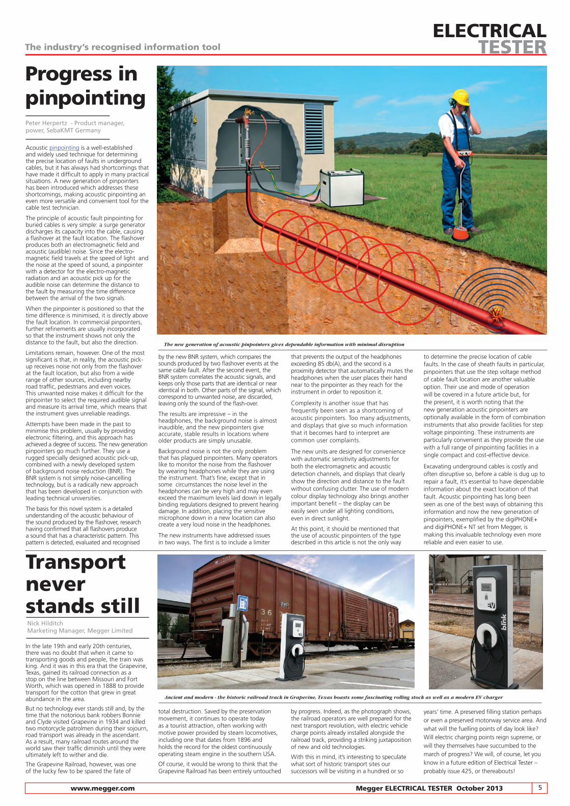
Acoustic pinpointing is a well-established and widely used technique for determining the precise location of faults in underground cables, but it has always had shortcomings that have made it difficult to apply in many practical situations. A new generation of pinpointers has been introduced which addresses these shortcomings, making acoustic pinpointing an even more versatile and convenient tool for the cable test technician.
The principle of acoustic fault pinpointing for buried cables is very simple: a surge generator discharges its capacity into the cable, causing a flashover at the fault location. The flashover produces both an electromagnetic field and acoustic (audible) noise. Since the electro- magnetic field travels at the speed of light and the noise at the speed of sound, a pinpointer with a detector for the electro-magnetic radiation and an acoustic pick up for the audible noise can determine the distance to the fault by measuring the time difference between the arrival of the two signals.
When the pinpointer is positioned so that the time difference is minimised, it is directly above the fault location. In commercial pinpointers, further refinements are usually incorporated so that the instrument shows not only the distance to the fault, but also the direction.
Limitations remain, however. One of the most significant is that, in reality, the acoustic pick-up receives noise not only from the flashover at the fault location, but also from a wide range of other sources, including nearby road traffic, pedestrians and even voices. This unwanted noise makes it difficult for the pinpointer to select the required audible signal and measure its arrival time, which means that the instrument gives unreliable readings.
Attempts have been made in the past to minimise this problem, usually by providing electronic filtering, and this approach has achieved a degree of success. The new generation pinpointers go much further. They use a rugged specially designed acoustic pick-up, combined with a newly developed system of background noise reduction (BNR). The BNR system is not simply noise-cancelling technology, but is a radically new approach that has been developed in conjunction with leading technical universities.
The basis for this novel system is a detailed understanding of the acoustic behaviour of the sound produced by the flashover, research having confirmed that all flashovers produce a sound that has a characteristic pattern. This pattern is detected, evaluated and recognised
by the new BNR system, which compares the sounds produced by two flashover events at the same cable fault. After the second event, the BNR system correlates the acoustic signals, and keeps only those parts that are identical or near identical in both. Other parts of the signal, which correspond to unwanted noise, are discarded, leaving only the sound of the flash-over.
The results are impressive – in the headphones, the background noise is almost inaudible, and the new pinpointers give accurate, stable results in locations where older products are simply unusable.
Background noise is not the only problem that has plagued pinpointers. Many operators like to monitor the noise from the flashover by wearing headphones while they are using the instrument. That’s fine, except that in some circumstances the noise level in the headphones can be very high and may even exceed the maximum levels laid down in legally binding regulations designed to prevent hearing damage. In addition, placing the sensitive microphone down in a new location can also create a very loud noise in the headphones.
The new instruments have addressed issues in two ways. The first is to include a limiter
that prevents the output of the headphones exceeding 85 db(A), and the second is a proximity detector that automatically mutes the headphones when the user places their hand near to the pinpointer as they reach for the instrument in order to reposition it.
Complexity is another issue that has frequently been seen as a shortcoming of acoustic pinpointers. Too many adjustments, and displays that give so much information that it becomes hard to interpret are common user complaints.
The new units are designed for convenience with automatic sensitivity adjustments for both the electromagnetic and acoustic detection channels, and displays that clearly show the direction and distance to the fault without confusing clutter. The use of modern colour display technology also brings another important benefit – the display can be easily seen under all lighting conditions, even in direct sunlight.
At this point, it should be mentioned that the use of acoustic pinpointers of the type described in this article is not the only way
to determine the precise location of cable faults. In the case of sheath faults in particular, pinpointers that use the step voltage method of cable fault location are another valuable option. Their use and mode of operation will be covered in a future article but, for the present, it is worth noting that the new generation acoustic pinpointers are optionally available in the form of combination instruments that also provide facilities for step voltage pinpointing. These instruments are particularly convenient as they provide the use with a full range of pinpointing facilities in a single compact and cost-effective device.
Excavating underground cables is costly and often disruptive so, before a cable is dug up to repair a fault, it’s essential to have dependable information about the exact location of that fault. Acoustic pinpointing has long been seen as one of the best ways of obtaining this information and now the new generation of pinpointers, exemplified by the digiPHONE+ and digiPHONE+ NT set from Megger, is making this invaluable technology even more reliable and even easier to use.
Peter Herpertz - Product manager, power, SebaKMT Germany
Progress in pinpointing
Transport never stands still
The industry’s recognised information toolELECTRICAL
TESTER
The new generation of acoustic pinpointers gives dependable information with minimal disruption
In the late 19th and early 20th centuries, there was no doubt that when it came to transporting goods and people, the train was king. And it was in this era that the Grapevine, Texas, gained its railroad connection as a stop on the line between Missouri and Fort Worth, which was opened in 1888 to provide transport for the cotton that grew in great abundance in the area.
But no technology ever stands still and, by the time that the notorious bank robbers Bonnie and Clyde visited Grapevine in 1934 and killed two motorcycle patrolmen during their sojourn, road transport was already in the ascendant. As a result, many railroad routes around the world saw their traffic diminish until they were ultimately left to wither and die.
The Grapevine Railroad, however, was one of the lucky few to be spared the fate of
total destruction. Saved by the preservation movement, it continues to operate today as a tourist attraction, often working with motive power provided by steam locomotives, including one that dates from 1896 and holds the record for the oldest continuously operating steam engine in the southern USA.
Of course, it would be wrong to think that the Grapevine Railroad has been entirely untouched
by progress. Indeed, as the photograph shows, the railroad operators are well prepared for the next transport revolution, with electric vehicle charge points already installed alongside the railroad track, providing a striking juxtaposition of new and old technologies.
With this in mind, it’s interesting to speculate what sort of historic transport sites our successors will be visiting in a hundred or so
years’ time. A preserved filling station perhaps or even a preserved motorway service area. And what will the fuelling points of day look like? Will electric charging points reign supreme, or will they themselves have succumbed to the march of progress? We will, of course, let you know in a future edition of Electrical Tester – probably issue 425, or thereabouts!
Ancient and modern - the historic railroad track in Grapevine, Texas boasts some fascinating rolling stock as well as a modern EV charger
Nick HilditchMarketing Manager, Megger Limited
6 Megger ELECTRICAL TESTER October 2013 www.megger.com
The industry’s recognised information toolELECTRICAL
TESTER
There are two main reasons for testing power cables; to determine the condition of the cable, and to locate a fault on the cable. This article, which is the second in our series on power cable testing, provides an overview of a systematic approach for each of these cases, and then goes on to discuss fault classification.
A SYSTEMATIC APPROACH
Testing cable conditionThe objective of the test is typically to check the quality a cable before installing it, or to detect and remedy potential defects in the cable, which might otherwise jeopardise reliable operation.
When testing a cable for potential defects, a common technique is to generate flashovers at the sites of the defects, which can then be located using the standard fault location techniques mentioned later. Depending on the type of cable insulation and the type of test object (cable or accessory), the following types of test voltage should be used:
Paper insulated lead-covered cable (PILC) DC voltage AC voltage 50/60 Hz VLF (0.1 Hz)PE/XLPE cable AC voltage 50/60 Hz VLF (0.1 Hz)Components (joints, terminations, etc.) DC voltage AC voltage 50/60 Hz
Alternatively, the cable can be tested non-destructively using dielectric diagnosis and partial discharge techniques. The first diagnostic technology is the Tan Delta technology, based on 0.1 Hz VLF voltage for most insulation materials.
In cables with PE and XLPE insulation, dielectric diagnosis based on IRC (isothermal relaxation current) analysis makes it possible to determine how much the cable has aged, while with PILC cables, RVM (return voltage measurement) analysis allows the moisture content of the dielectric to be accurately assessed. Partial discharge measurement is used for recording, locating and evaluating partial discharges in the insulation and fittings of medium voltage cables, and can reveal a wide range of actual and potential defects.
Cable fault location
The steps needed for determining cable fault locations can be divided into five main categories:
� fault classification – identifying the type of fault
� pre-location – determining the distance to the fault
� route tracing – determining the route of the cable
� pinpointing – determining the exact position of the fault
� cable identification – determining which of several cables is faulty
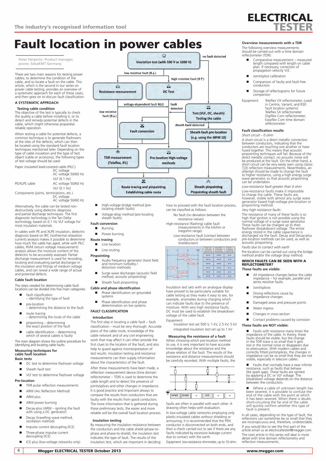
The main diagram shows the outline procedure for identifying and locating cable faults.
Measuring techniques for cable fault locationBasic tests
� DC test to determine flashover voltage
� Sheath fault test
� VLF test to determine flashover voltage
Pre-location � TDR pulse reflection measurements
� ARM (Arc Reflection Method)
� ARM plus
� ARM power burning
� Decay-plus (ARM – igniting the fault with using a DC generator)
� Decay (travelling wave method, oscillation method)
� Impulse current decoupling (ICE)
� Three-phase impulse current decoupling (ICE)
� ICE plus (low-voltage networks only)
� High-voltage bridge method (pre- locating sheath faults)
� Voltage-drop method (pre-locating sheath faults)
Fault conversion � Burning
� Power burning
Route tracing � Line location
� Line routing
Pinpointing � Audio frequency generator (twist field
and minimum turbidity / distortion methods)
� Surge wave discharges (acoustic field method, acoustic pinpointing)
� Sheath fault pinpointing
Cable and phase identification � Phase identification on grounded
systems
� Phase identification and phase determination on live systems
FAULT CLASSIFICATION
IntroductionThe first step in locating a cable fault – fault classification – must be very thorough. Accurate plans of the cable route, knowledge of the cable network and of any civil engineering work that may affect it can often provide the first clues to the location of the fault, and also help to guard against misinterpretation of test results. Insulation testing and resistance measurements can then supply information about the characteristics of the fault.
After these measurements have been made, a reflection measurement device (time domain reflectometer – TDR) is used to determine the cable length and to detect the presence of joints/splices and other changes in impedance. It is good practice and important always to compare the results from conductors that are faulty with the results from good conductors. The more information that is gathered during these preliminary tests, the easier and more reliable will be the overall fault location process.
Insulation testingBy measuring the insulation resistance between the conductors and the cable shield (phase-to-phase and phase-to-shield), the insulation test indicates the type of fault. The results of the insulation test, which are important in deciding
how to proceed with the fault location process, can be classified as follows:
No fault (no deviation between the resistance values)High-resistance (flashing) cable fault (measurements in the kilohm or megohm range) Low-resistance fault (contact between conductors or between conductors and shield/screen)
Insulation test sets with an analogue display have proved to be particularly suitable for cable testing as they make it easy to see, for example, anomalies during charging which can indicate faults due to the presence of moisture. With very high resistance faults, DC must be used to establish the breakdown voltage of the cable fault.Equipment: insulation test set 500 V, 1 kV, 2.5 kV, 5 kV integrated insulation test set up to 1 kV
Measuring the resistance of a faultWhen choosing which pre-location method to use, it is very important to have accurate knowledge about the resistance and the phase relation of the fault. The results of the resistance and distance measurements should be carefully recorded. With multiple faults, the
faults are often in parallel with each other. A drawing often helps with evaluation.
In low-voltage cable networks employing only plastic-insulated cables without shielding or armouring, it is recommended that the PEN conductor is disconnected on both ends, and then a check carried out to see if there are any faults indicated by excessive leakage current due to contact with the earth.Equipment: low-resistance ohmmeter, up to 10 ohm.
Overview measurements with a TDRThe following overview measurements should be carried out with a time domain reflectometer (TDR):
� Comparative measurement – measured length compared with length on cable plan. If necessary, correction of propagation velocity V/2.
� Joint/splice calibration
� Comparison of faulty and fault-free conductors
� Storage of reflectograms for future comparison
Equipment: Teleflex VX reflectometer, (used in Centrix, Variant, and R30 fault location systems) Teleflex SX reflectometer Digiflex Com reflectometer, Easyflex Com time domain reflectometer. Fault classification results Short circuit – 0 ohmA short circuit is a direct metallic connection between conductors, indicating that the conductors are touching one another or have fused together. This means that acoustic pinpointing techniques will fail. Because of the direct metallic contact, no acoustic noise will be produced at the fault. On the other hand, a short circuit can be very easily seen using classic TDR reflection measurements. Nevertheless, an attempt should be made to change the fault to higher resistance, using a high energy surge wave generator, so that acoustic pinpointing can be undertaken.Low-resistance fault greater than 0 ohmLow-resistance faults make it impossible to charge the cable. These faults are, however, visible with almost any surge wave generator based high-voltage pre-location or pinpointing method.Very high resistance faultsThe resistance of many of these faults is so high that ignition is not possible using the normal voltage of a surge wave generator. These faults can be charged up to their flashover (breakdown) voltage. The entire energy stored in the cable capacitance is discharged via the fault. Decay and Decay-plus pre-location methods can be used, as well as acoustic pinpointing.Faults due to contact with earthPre-location can be carried out using the bridge method and/or the voltage drop method.
WHICH FAULTS CAN BE SEEN WITH A REFLECTOMETER?These faults are visible:
� All impedance changes below the cable impedance – for example, parallel and series resistive faults
� Joint/splices
� Strong reflections cause by impedance changes
� Damaged areas and pressure points
� Water ingress
� Changes in cross-section
� Contact problems caused by corrosion
These faults are NOT visible:
� Faults with resistance many times the impedance of the cable. In theory, these faults should be visible, but the change in the TDR trace is so small that it gets lost in the normal noise or disappears due to attenuation. With modern cables and correctly fitted joints/splices, the changes in impedance can be so small that they are not visible, especially in telecom cables.
� Faults that normally have a near infinite resistance, such as faults that behave like spark gaps. These faults are ignited by applying a DC or VLF voltage. The breakdown voltage depends on the distance between the conductors.
� Where a cable of unknown length has been severed, it is possible to confuse the end of the cable with the point at which it has been severed. When there is doubt, short-circuiting the far end of the cable will quickly confirm whether this type of fault is present.
In all cases, depending on the type of fault, the reflections can sometimes be so small that they are inconspicuous and, therefore, undetectable.If you would like to see the first part of the article email us at [email protected] next article in this series will deal in more detail with time domain reflectometry and reflection measurements.
Fault location in power cablesPeter Herpertz- Product manager, power, SebaKMT Germany

7 www.megger.com Megger ELECTRICAL TESTER October 2013
Remote control of insulation testing
The industry’s recognised information toolELECTRICAL
TESTER
Enhanced safety, greater convenience and the possibility of automation are just three of the important benefits offered by high-voltage insulation test sets that have provision for remote control. In this article, we discuss these and other benefits, and also look at some applications where they are of particular value.
Traditionally, high-voltage insulation resistance testers (IRTs) have been designed for manual operation; the user connects the instrument to the device under test (DUT) and, after setting the operating parameters, presses the test button on the instrument itself to initiate the test. For many applications, this method of working is convenient and entirely appropriate, but that’s not always the case.
Consider, for example, a motor manufacturer who, in order to improve productivity and reduce labour costs, wishes to automate insulation resistance testing of items like stators and rotors, or even smaller components like rotor bars, as they come off the production line. Undoubtedly a test jig will be used to provide the necessary connections to the item under test, but the test itself can only be carried out automatically if an IRT with facilities for remote control and test result transfer is used.
Remote control also offers big advantages in testing transformers, circuit breakers and similar equipment routinely used in power transmission and distribution systems. In these applications, particularly when the testing is being carried out in an electrically noisy environment, it is advantageous to keep the test connections as short as possible. However, if testing is being carried out on top of a large transformer, keeping the connections short inevitably means that the IRT will be in
a hard-to-access location and, quite apart from the inconvenience, if the IRT has to be operated locally, there may well be safety concerns over working at height with HV equipment. Remote control provides a complete solution, as it means that even if the tester is on top of the transformer, it can be operated safely and conveniently from ground level.
Working at height is far from being the only safety issue that remotely controlled insulation resistance testing can help to eliminate. Not infrequently, testing must be carried out in electrically hazardous environments, such as EHV substations. In such cases, once the test set has been put in place and connected, the user can, with the benefit of remote control, retreat to a safe distance, and perform the testing with virtually no risk. The IRT could even be left in place and monitored remotely in instances where it is necessary to look for changes in insulation resistance over a period of time.
Another interesting example is the testing of products during development. Because there may be a significant risk of the product failing during the test, it is often desirable to carry out such tests within a test cage or other enclosure. With remote control, the insulation tester can be conveniently located within the enclosure and connected to the DUT by short leads, while the operator initiates the tests from a safe location outside the enclosure.
With such an arrangement, it is also easily possible to use a solenoid-operated lock on the enclosure door, and arrange for this to be
linked with the test set’s remote-control system so that the test cannot be initiated until the door is proved closed and locked, and the door cannot be opened while the test is in progress.
Siemens Subsea is an example of a company that has benefited from some of these options, as Chris Harrison, a senior engineer with the company explains.
“For us, insulation testing is a commonplace activity. The introduction of a remotely operable IRT is allowing us to improve our electrical testing safety, as it means we can now site the IRTs within interlocked test bays. A further advantage is that with the remote control facility, we can control the testing from our in-house software, which means we can semi-automate certain processes.”
“This offers significant time savings, and reduces our paperwork burden by allowing us to log test data directly to our own network locations. At Siemens Subsea, the availability of a remotely operable IRT has made it possible for us to take an exciting step forward toward our long-term goal of semi-automating our test routines.”
There are many other applications where the opportunity for automation offered by remote control is a major benefit. These include the testing of underwater cable during manufacture, where the insulation resistance test has to be repeated at regular intervals while the pressure on the cable – which is held in a pressurised tank during testing – is raised.
Similarly, it is usually considered desirable to perform regular insulation resistance tests on
underwater power cables during the cable laying operation, so that any problems can be immediately detected. Automation, made possible by an IRT with remote operation facilities is the key, allowing the necessary tests to be performed reliably and on-schedule without the need for operator intervention.
It’s clear that remote control of HV IRTs, while a simple concept, has much to offer, but its full potential will only be realised if it is well implemented. A crucial requirement is impeccable isolation between the remote control interface and the measuring circuits, as this is essential for safe operation. And particularly in production line applications, a clearly visible beacon that provides at-a-glance confirmation that the remote control system is functioning is often a useful feature.
Until recently, finding an IRT to meet these requirements was difficult. The new S1 range of HV insulation testers which are available in both 5 kV and 10 kV versions, constitute a new generation of instruments that have been designed with remote control – and other features needed by demanding users, such as exceptional noise immunity – firmly in mind.
Providing remote control facilities for a high-voltage insulation test set may initially seem like a relatively small enhancement but this provision has the potential to open up a wide range of operational opportunities, and to provide many ways of improving operator safety. If you’re about to buy a new HV IRT, therefore, you may well find it worthwhile considering looking for a product that offers well-implemented remote control.
Clive Pink, new product development manager, Megger Instruments Limited
Engineering is, for the most part, a serious
business but it does have a quirky side that can
be both entertaining and amusing. And, if you
want a glimpse of this quirky side, there are
few better places to look than the Eccentric
Engineer column that appears regularly in E&T,
a magazine published by the UK’s Institution of
Engineering and Technology (the IET).
But maybe you don’t receive the magazine or
perhaps you just don’t have time to read it.
In either case, ‘Buses, Bankers and the Beer of
Revenge’, a new book by Justin Pollard, will
make sure that you don’t miss out. A collection
of 50 of the best stories from the Eccentric
Engineering column, it’s a delightful and
amusing read for anyone with an engineering
background. My only caution is that, once I’d
starting reading, I found it hard to stop, so it might be better to keep the book at home rather than on your desk!
I don’t want to spoil your fun by telling you too much about the content, but one example surely won’t hurt. Did you know that in the late 18th century there was much bitter contention about whether lightning conductors should be pointed or have knobs on the end? And that one of the principal supporters of pointy conductors was none other than Benjamin Franklin, who also signed the American Declaration of Independence? Even King George III got involved – on the side of the knobs, of course!
This book is an entertaining read and a great
way of passing a few spare minutes. Reading
it probably doesn’t quite qualify as continuing
professional development, but it will certainly
introduce you to (vaguely) engineering ideas and
concepts that you’re not likely to find elsewhere!
‘Buses, Bankers and the Beer of Revenge’ is available in hardback from the IET on-line bookshop for a mere £15 / $23 / €18. The hardback version is also available from local
Amazon sites or, if you’re so enthusiastic that
you would like to start reading it in the next
few minutes, there’s also a Kindle version.
The quirky side of engineering
Using the remote control can make testing quicker, easier, and above all safer
When choosing an insulation resistance tester, make sure the main controls can be operated with a glove
The most up-to-date insulation resistance testers offer high noise immunity, remote control and ease of use
Keith WilsonElectrical Engineer
Lightning conductors: pointed or with a knob on the end?
8 Megger ELECTRICAL TESTER October 2013 www.megger.com
Q&A High-voltage insulation testing at 5 kV and 10 kV is a subject that comes up regularly in the questions received by our technical support group, so in this issue we’re providing answers for some of the questions we’re most frequently asked in relation to this important and interesting topic.
The industry’s recognised information toolELECTRICAL
TESTER
Q: Is there any good reason to choose an insulation test set that offers a high output current as preference to one with a lower output current?
A: There are actually several reasons to choose a test set with a high output current. Possibly the most important is that a high output current will mean that the item under test will be charged more quickly, which means that the test can be completed in a shorter time, and also that there’s less risk that the readings will be taken before the test voltage has had time to stabilise properly. And, if you’re using the instrument’s guard terminal, don’t forget that a lot of output current may
well be diverted via the surface leakage of the item under test. Unless the instrument has a high output current capability, this could mean that the output voltage will collapse and the test results will not be valid.
Q: Sometimes it seems impossible to get
consistent test results when performing
insulation tests – the readings just won’t
stabilise. This seems to happen a lot,
for example, in substations. What’s the
problem, and what can be done about it?
A: In cases of this type, the source of the trouble is almost always induced noise in the measuring circuit. Noise pick up on the test leads can be reduced by keeping them as short as possible, and by using screened test leads.
With screened leads, the screen is connected to the insulation test set guard terminal, so that the noise currents are diverted away from the measuring circuits. These measures can’t help, however, if the noise is being picked up by the item under test rather than the test leads. In such cases, the only effective solution is to use an insulation test set with high noise immunity and effective filtering. Instruments are now available with noise immunity of 8 mA, which is enough to ensure reliable operation in the toughest conditions, such as EHV substations. They also have adjustable long time constant filtering, which allows users to choose between faster operation, when noise levels are only moderate, and slower operation but enhanced noise rejection when working in the most challenging environments.
Q: Why do some of the latest insulation
testers have facilities for remote control?
A: These facilities are useful in a wide range of applications. For example, when testing a large item such as a power transformer, the tester can be positioned on top of the item near to the terminals so that the test leads are kept short, and operated from a much more convenient – and much safer – location, using the remote control option. Also, it’s sometimes necessary to carry out tests in locations that are hazardous, such as inside an energised sub-station. In these cases, once it has been connected, the test set can be operated from outside of the hazardous area, greatly increasing the safety of the operator. Finally, in production line test applications, it’s often desirable to control the tester automatically, and the remote control facility offers a convenient way of achieving this, and of providing any safety interlocks that may be needed.
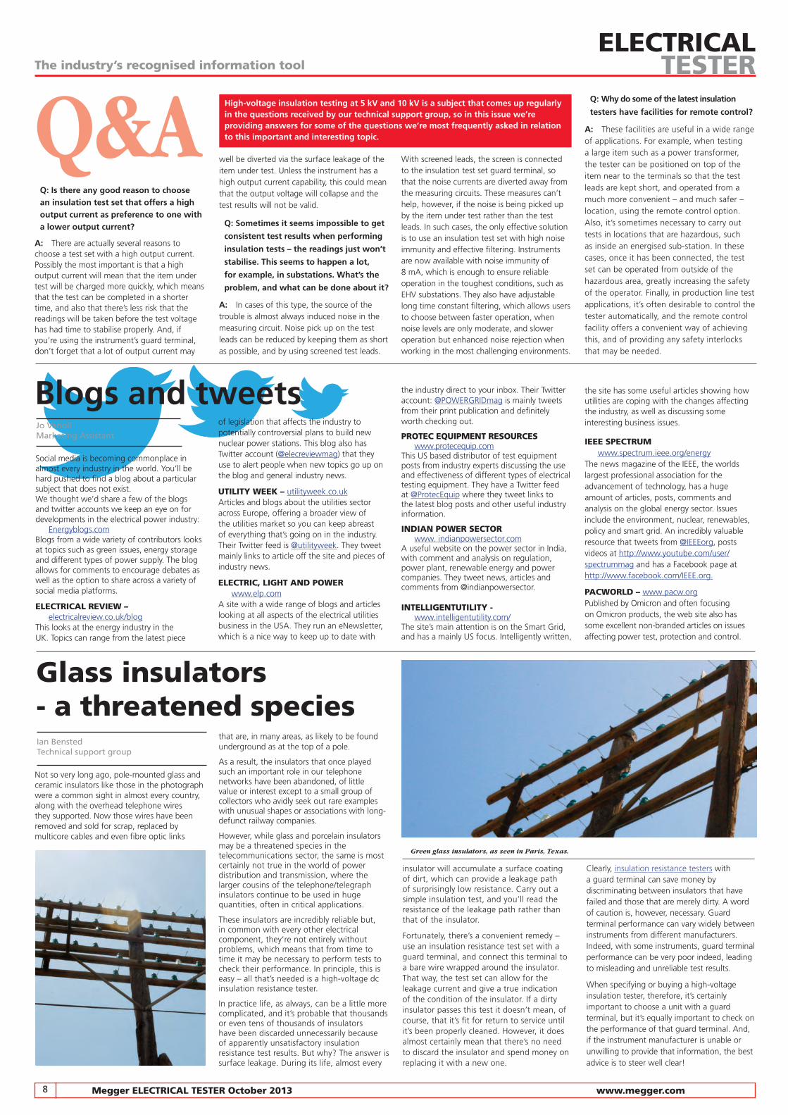
Glass insulators - a threatened speciesIan BenstedTechnical support group
Blogs and tweetsJo VanoliMarketing Assistant
of legislation that affects the industry to potentially controversial plans to build new nuclear power stations. This blog also has Twitter account (@elecreviewmag) that they use to alert people when new topics go up on the blog and general industry news.
UTILITY WEEK – utilityweek.co.ukArticles and blogs about the utilities sector across Europe, offering a broader view of the utilities market so you can keep abreast of everything that’s going on in the industry. Their Twitter feed is @utilityweek. They tweet mainly links to article off the site and pieces of industry news.
ELECTRIC, LIGHT AND POWER www.elp.comA site with a wide range of blogs and articles looking at all aspects of the electrical utilities business in the USA. They run an eNewsletter, which is a nice way to keep up to date with
Social media is becoming commonplace in almost every industry in the world. You’ll be hard pushed to find a blog about a particular subject that does not exist. We thought we’d share a few of the blogs and twitter accounts we keep an eye on for developments in the electrical power industry: Energyblogs.comBlogs from a wide variety of contributors looks at topics such as green issues, energy storage and different types of power supply. The blog allows for comments to encourage debates as well as the option to share across a variety of social media platforms.
ELECTRICAL REvIEW – electricalreview.co.uk/blogThis looks at the energy industry in the UK. Topics can range from the latest piece
the industry direct to your inbox. Their Twitter account: @POWERGRIDmag is mainly tweets from their print publication and definitely worth checking out.
PROTEC EQUIPMENT RESOURCES www.protecequip.comThis US based distributor of test equipment posts from industry experts discussing the use and effectiveness of different types of electrical testing equipment. They have a Twitter feed at @ProtecEquip where they tweet links to the latest blog posts and other useful industry information.
INDIAN POWER SECTOR www. indianpowersector.comA useful website on the power sector in India, with comment and analysis on regulation, power plant, renewable energy and power companies. They tweet news, articles and comments from @indianpowersector.
INTELLIGENTUTILITY - www.intelligentutility.com/ The site’s main attention is on the Smart Grid, and has a mainly US focus. Intelligently written,
the site has some useful articles showing how utilities are coping with the changes affecting the industry, as well as discussing some interesting business issues.
IEEE SPECTRUM www.spectrum.ieee.org/energyThe news magazine of the IEEE, the worlds largest professional association for the advancement of technology, has a huge amount of articles, posts, comments and analysis on the global energy sector. Issues include the environment, nuclear, renewables, policy and smart grid. An incredibly valuable resource that tweets from @IEEEorg, posts videos at http://www.youtube.com/user/spectrummag and has a Facebook page at http://www.facebook.com/IEEE.org.
PACWORLD – www.pacw.orgPublished by Omicron and often focusing on Omicron products, the web site also has some excellent non-branded articles on issues affecting power test, protection and control.
Not so very long ago, pole-mounted glass and ceramic insulators like those in the photograph were a common sight in almost every country, along with the overhead telephone wires they supported. Now those wires have been removed and sold for scrap, replaced by multicore cables and even fibre optic links
that are, in many areas, as likely to be found underground as at the top of a pole.
As a result, the insulators that once played such an important role in our telephone networks have been abandoned, of little value or interest except to a small group of collectors who avidly seek out rare examples with unusual shapes or associations with long-defunct railway companies.
However, while glass and porcelain insulators may be a threatened species in the telecommunications sector, the same is most certainly not true in the world of power distribution and transmission, where the larger cousins of the telephone/telegraph insulators continue to be used in huge quantities, often in critical applications.
These insulators are incredibly reliable but, in common with every other electrical component, they’re not entirely without problems, which means that from time to time it may be necessary to perform tests to check their performance. In principle, this is easy – all that’s needed is a high-voltage dc insulation resistance tester.
In practice life, as always, can be a little more complicated, and it’s probable that thousands or even tens of thousands of insulators have been discarded unnecessarily because of apparently unsatisfactory insulation resistance test results. But why? The answer is surface leakage. During its life, almost every
insulator will accumulate a surface coating of dirt, which can provide a leakage path of surprisingly low resistance. Carry out a simple insulation test, and you’ll read the resistance of the leakage path rather than that of the insulator.
Fortunately, there’s a convenient remedy – use an insulation resistance test set with a guard terminal, and connect this terminal to a bare wire wrapped around the insulator. That way, the test set can allow for the leakage current and give a true indication of the condition of the insulator. If a dirty insulator passes this test it doesn’t mean, of course, that it’s fit for return to service until it’s been properly cleaned. However, it does almost certainly mean that there’s no need to discard the insulator and spend money on replacing it with a new one.
Clearly, insulation resistance testers with a guard terminal can save money by discriminating between insulators that have failed and those that are merely dirty. A word of caution is, however, necessary. Guard terminal performance can vary widely between instruments from different manufacturers. Indeed, with some instruments, guard terminal performance can be very poor indeed, leading to misleading and unreliable test results.
When specifying or buying a high-voltage insulation tester, therefore, it’s certainly important to choose a unit with a guard terminal, but it’s equally important to check on the performance of that guard terminal. And, if the instrument manufacturer is unable or unwilling to provide that information, the best advice is to steer well clear!
Green glass insulators, as seen in Paris, Texas.