Embed Size (px)
Citation preview
BODY ELECTRICAL SYSTEM
–BODY ELECTRICAL SYSTEMBE–1
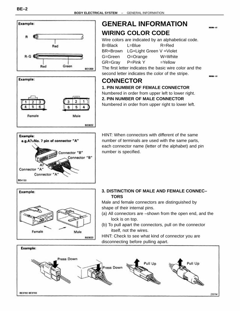
GENERAL INFORMATIONWIRING COLOR CODEWire colors are indicated by an alphabetical code.B=Black L=Blue R=RedBR=Brown LG=Light Green V =VioletG=Green O=Orange W=WhiteGR=Gray P=Pink Y =YellowThe first letter indicates the basic wire color and thesecond letter indicates the color of the stripe.
CONNECTOR1. PIN NUMBER OF FEMALE CONNECTORNumbered in order from upper left to lower right.2. PIN NUMBER OF MALE CONNECTORNumbered in order from upper right to lower left.
3. DISTINCTION OF MALE AND FEMALE CONNEC–TORS
Male and female connectors are distinguished byshape of their internal pins.(a) All connectors are –shown from the open end, and the
lock is on top.(b) To pull apart the connectors, pull on the connector
itself, not the wires.HINT: Check to see what kind of connector you aredisconnecting before pulling apart.
HINT: When connectors with different of the samenumber of terminals are used with the same parts,each connector name (letter of the alphabet) and pinnumber is specified.
–BODY ELECTRICAL SYSTEM GENERAL INFORMATIONBE–2
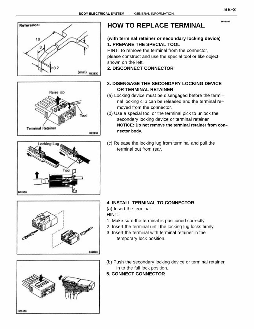
3. DISENGAGE THE SECONDARY LOCKING DEVICEOR TERMINAL RETAINER
(a) Locking device must be disengaged before the termi–nal locking clip can be released and the terminal re–moved from the connector.
(b) Use a special tool or the terminal pick to unlock thesecondary locking device or terminal retainer.NOTICE: Do not remove the terminal retainer from con–nector body.
HOW TO REPLACE TERMINAL
(with terminal retainer or secondary locking device)1. PREPARE THE SPECIAL TOOLHINT: To remove the terminal from the connector,please construct and use the special tool or like objectshown on the left.2. DISCONNECT CONNECTOR
4. INSTALL TERMINAL TO CONNECTOR(a) Insert the terminal.HINT:1. Make sure the terminal is positioned correctly.2. Insert the terminal until the locking lug locks firmly.3. Insert the terminal with terminal retainer in the
temporary lock position.
(b) Push the secondary locking device or terminal retainerin to the full lock position.
5. CONNECT CONNECTOR
(c) Release the locking lug from terminal and pull theterminal out from rear.
–BODY ELECTRICAL SYSTEM GENERAL INFORMATIONBE–3
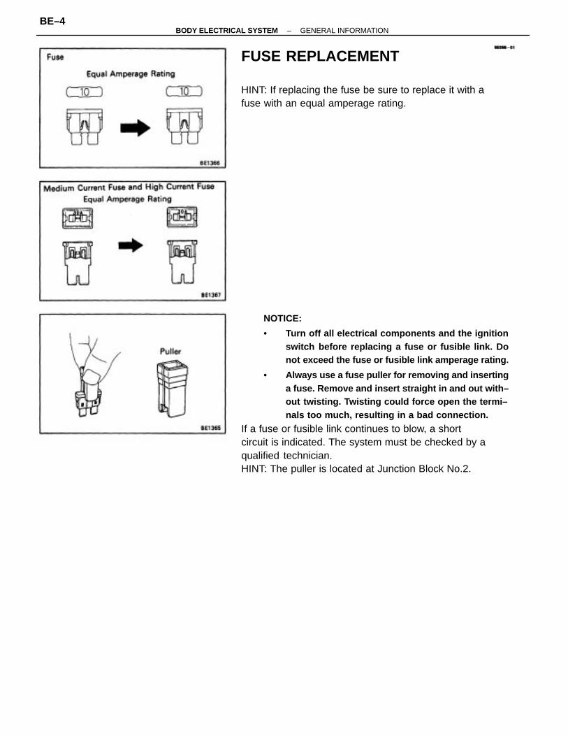
NOTICE:
• Turn off all electrical components and the ignitionswitch before replacing a fuse or fusible link. Donot exceed the fuse or fusible link amperage rating.
• Always use a fuse puller for removing and insertinga fuse. Remove and insert straight in and out with–out twisting. Twisting could force open the termi–nals too much, resulting in a bad connection.
If a fuse or fusible link continues to blow, a shortcircuit is indicated. The system must be checked by aqualified technician.HINT: The puller is located at Junction Block No.2.
FUSE REPLACEMENT
HINT: If replacing the fuse be sure to replace it with afuse with an equal amperage rating.
–BODY ELECTRICAL SYSTEM GENERAL INFORMATIONBE–4
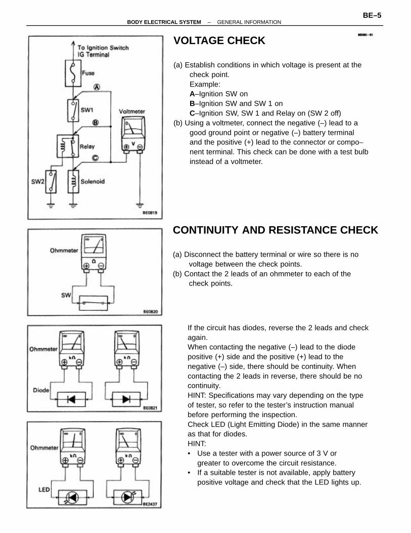
If the circuit has diodes, reverse the 2 leads and checkagain.When contacting the negative (–) lead to the diodepositive (+) side and the positive (+) lead to thenegative (–) side, there should be continuity. Whencontacting the 2 leads in reverse, there should be nocontinuity.HINT: Specifications may vary depending on the typeof tester, so refer to the tester’s instruction manualbefore performing the inspection.Check LED (Light Emitting Diode) in the same manneras that for diodes.HINT:• Use a tester with a power source of 3 V or
greater to overcome the circuit resistance.• If a suitable tester is not available, apply battery
positive voltage and check that the LED lights up.
VOLTAGE CHECK
(a) Establish conditions in which voltage is present at thecheck point.Example:A–Ignition SW onB–Ignition SW and SW 1 onC–Ignition SW, SW 1 and Relay on (SW 2 off)
(b) Using a voltmeter, connect the negative (–) lead to agood ground point or negative (–) battery terminaland the positive (+) lead to the connector or compo–nent terminal. This check can be done with a test bulbinstead of a voltmeter.
CONTINUITY AND RESISTANCE CHECK
(a) Disconnect the battery terminal or wire so there is novoltage between the check points.
(b) Contact the 2 leads of an ohmmeter to each of thecheck points.
–BODY ELECTRICAL SYSTEM GENERAL INFORMATIONBE–5
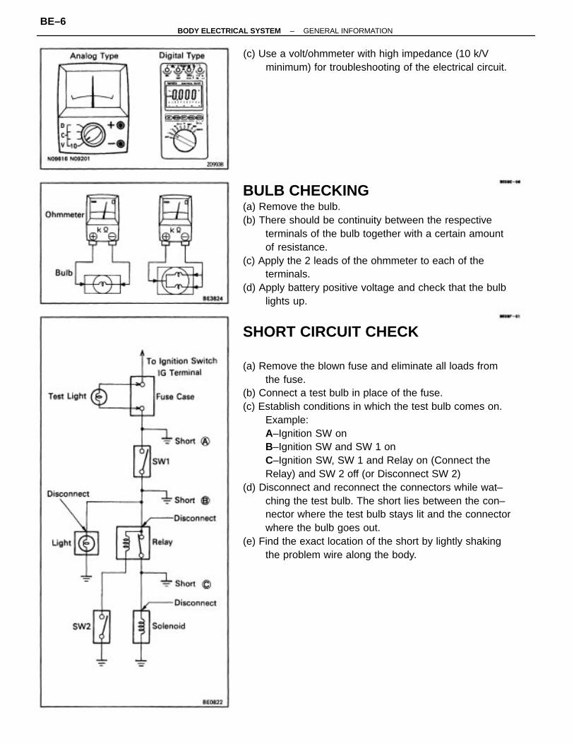
BULB CHECKING(a) Remove the bulb.(b) There should be continuity between the respective
terminals of the bulb together with a certain amountof resistance.
(c) Apply the 2 leads of the ohmmeter to each of theterminals.
(d) Apply battery positive voltage and check that the bulblights up.
SHORT CIRCUIT CHECK
(a) Remove the blown fuse and eliminate all loads fromthe fuse.
(b) Connect a test bulb in place of the fuse.(c) Establish conditions in which the test bulb comes on.
Example:A–Ignition SW onB–Ignition SW and SW 1 onC–Ignition SW, SW 1 and Relay on (Connect theRelay) and SW 2 off (or Disconnect SW 2)
(d) Disconnect and reconnect the connectors while wat–ching the test bulb. The short lies between the con–nector where the test bulb stays lit and the connectorwhere the bulb goes out.
(e) Find the exact location of the short by lightly shakingthe problem wire along the body.
(c) Use a volt/ohmmeter with high impedance (10 k/Vminimum) for troubleshooting of the electrical circuit.
–BODY ELECTRICAL SYSTEM GENERAL INFORMATIONBE–6
HEADLIGHT SYSTEM
• Halogen bulbs have pressurized gas inside and require special handling. They can burst orscatter if scratched or dropped. Hold a bulb only by its plastic or metal case.Don’t touch the glass part of a bulb with bare hands.
SRS (SUPPLEMENTAL RESTRAINT SYSTEM)
• Work must be started after 90 seconds from the time the ignition switch is turned to the”LOCK” position and the negative (–) terminal cable is disconnected from the battery.
• When disconnecting any of the connectors in the SRS, be sure to lock the ignition switch anddisconnect the negative (–) terminal cable from the battery first. Since the connectors aretwin lock type connectors, disconnect the connectors only after releasing the first stagelock.
• When connecting SRS connectors, be sure to lock them securely. (If the connectors are notlocked securely, the system may not operate when needed.)
• Always store the steering wheel pad with the pad surface facing upward. (Storing the padwith its metallic surface up may lead to a serious accident if the air bag inflates for somereason.)
• When installing the spiral cable, be sure the vehicle is in the straight ahead condition andconfirm that the spiral cable is in the neutral position when it is installed. (See page BE–28)
• INFORMATION LABELS (NOTICE) are attached to the periphery of the air bag components.Follow the NOTICE.
AUDIO SYSTEM• If the negative (–) terminal cable is disconnected from the battery, the preset AM, FM 1 and
FM 2 stations stored in memory are erased, so be sure to note the stations and reset themafter the battery terminal is reconnected.
• If the negative (–) terminal cable is disconnected from the battery, the ”ANTI–THEFTSYSTEM” will operate when the cable is reconnected, but the radio, tape player and CDplayer will not operate. Be sure to input the correct ID number so that the radio, tape playerand CD player can be operated again.
MOBILE COMMUNICATION SYSTEM• If the vehicle is equipped with a mobile communication system, refer to precautions in the IN
section.
PRECAUTIONTake care to observe the following precautions when performing inspections or remOval andreplacement of body electrical related parts.
–BODY ELECTRICAL SYSTEM PRECAUTIONBE–7
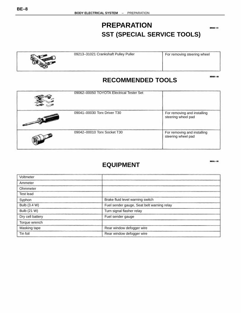
PREPARATIONSST (SPECIAL SERVICE TOOLS)
09062–00050 TOYOTA Electrical Tester Set
RECOMMENDED TOOLS
For removing and installingsteering wheel pad
For removing and installingsteering wheel pad
Fuel sender gauge, Seat belt warning relay
09213–31021 Crankshaft Pulley Puller
09042–00010 Torx Socket T30
09041–00030 Torx Driver T30
Brake fluid level warning switch
Rear window defogger wire
For removing steering wheel
Rear window defogger wire
Turn signal flasher relay
EQUIPMENT
Fuel sender gaugeDry cell battery
Torque wrench
Masking tape
Bulb (3.4 W)
Bulb (21 W)
Ohmmeter
Voltmeter
Test lead
Ammeter
Syphon
Tin foil
–BODY ELECTRICAL SYSTEM PREPARATIONBE–8
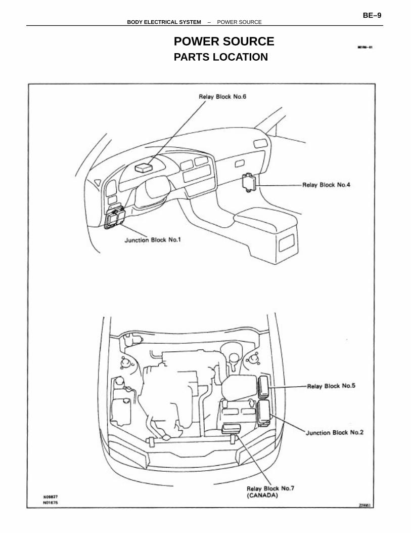
POWER SOURCEPARTS LOCATION
–BODY ELECTRICAL SYSTEM POWER SOURCEBE–9
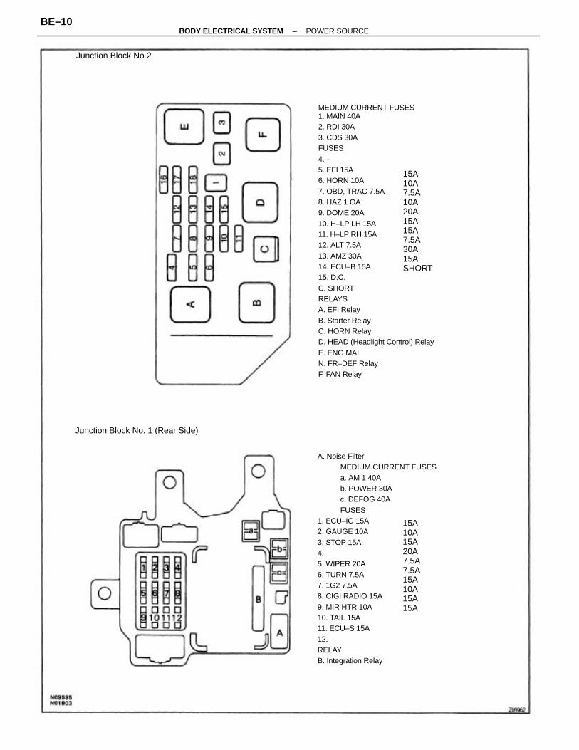
MEDIUM CURRENT FUSES1. MAIN 40A2. RDI 30A3. CDS 30AFUSES4. –5. EFI 15A6. HORN 10A7. OBD, TRAC 7.5A8. HAZ 1 OA9. DOME 20A10. H–LP LH 15A11. H–LP RH 15A12. ALT 7.5A13. AMZ 30A14. ECU–B 15A15. D.C.C. SHORTRELAYSA. EFI RelayB. Starter RelayC. HORN RelayD. HEAD (Headlight Control) RelayE. ENG MAIN. FR–DEF RelayF. FAN Relay
A. Noise FilterMEDIUM CURRENT FUSESa. AM 1 40Ab. POWER 30Ac. DEFOG 40AFUSES
1. ECU–IG 15A2. GAUGE 10A3. STOP 15A4.5. WIPER 20A6. TURN 7.5A7. 1G2 7.5A8. CIGI RADIO 15A9. MIR HTR 10A10. TAIL 15A11. ECU–S 15A12. –RELAYB. Integration Relay
15A10A7.5A10A20A15A15A7.5A30A15ASHORT
15A10A15A20A7.5A7.5A15A10A15A15A
Junction Block No. 1 (Rear Side)
Junction Block No.2
–BODY ELECTRICAL SYSTEM POWER SOURCEBE–10
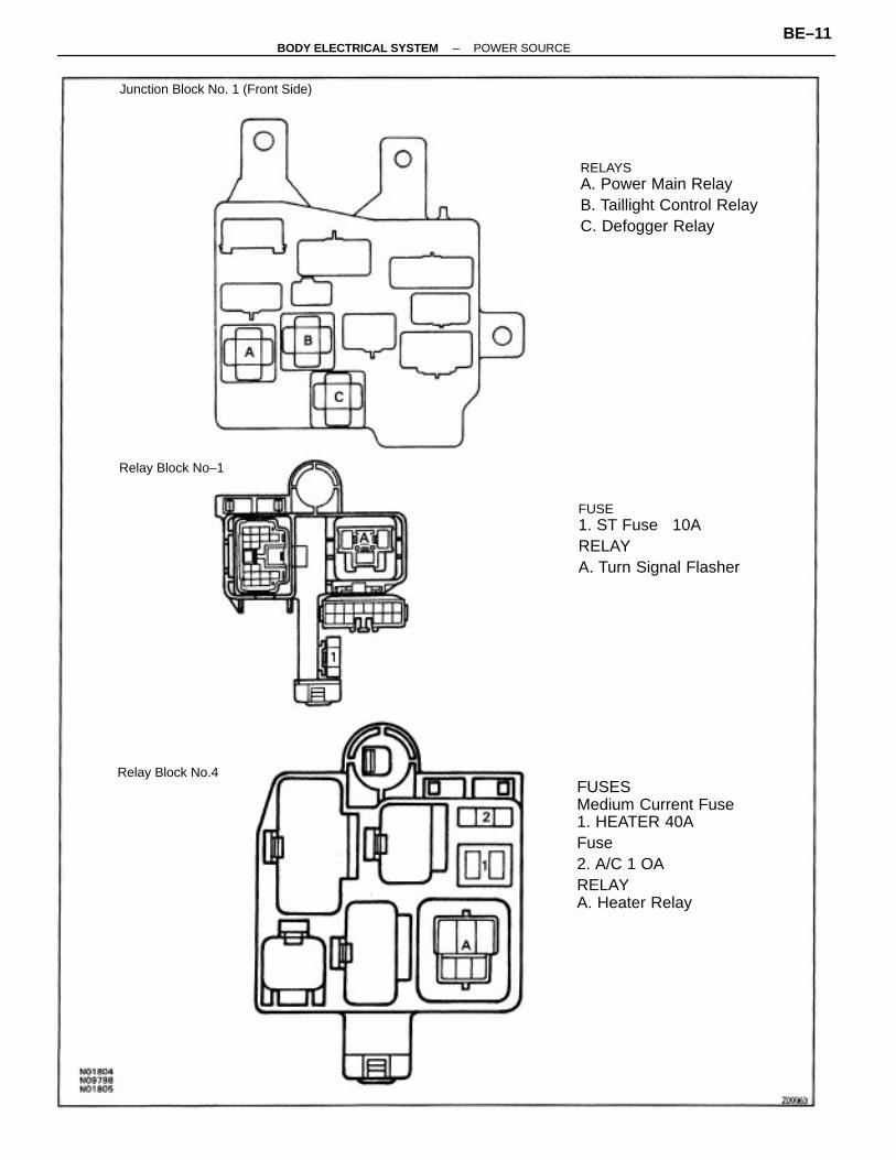
FUSESMedium Current Fuse1. HEATER 40AFuse2. A/C 1 OARELAYA. Heater Relay
FUSE1. ST Fuse 10ARELAYA. Turn Signal Flasher
RELAYSA. Power Main RelayB. Taillight Control RelayC. Defogger Relay
Junction Block No. 1 (Front Side)
Relay Block No–1
Relay Block No.4
–BODY ELECTRICAL SYSTEM POWER SOURCEBE–11
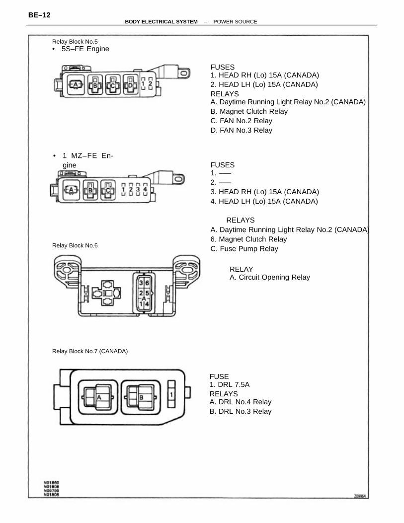
FUSES1. –––2. –––3. HEAD RH (Lo) 15A (CANADA)4. HEAD LH (Lo) 15A (CANADA)
RELAYSA. Daytime Running Light Relay No.2 (CANADA)6. Magnet Clutch RelayC. Fuse Pump Relay
FUSES1. HEAD RH (Lo) 15A (CANADA)2. HEAD LH (Lo) 15A (CANADA)RELAYSA. Daytime Running Light Relay No.2 (CANADA)B. Magnet Clutch RelayC. FAN No.2 RelayD. FAN No.3 Relay
FUSE1. DRL 7.5ARELAYSA. DRL No.4 RelayB. DRL No.3 Relay
RELAYA. Circuit Opening Relay
Relay Block No.5• 5S–FE Engine
Relay Block No.7 (CANADA)
• 1 MZ–FE En-gine
Relay Block No.6
–BODY ELECTRICAL SYSTEM POWER SOURCEBE–12
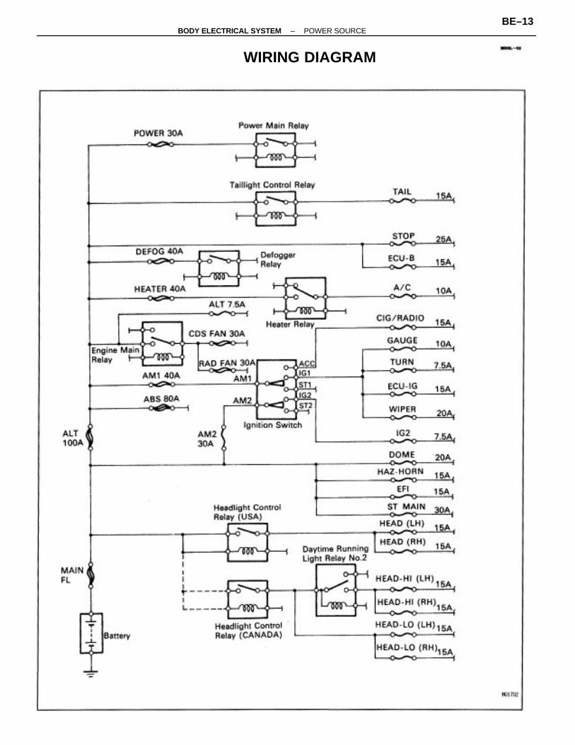
WIRING DIAGRAM
–BODY ELECTRICAL SYSTEM POWER SOURCEBE–13
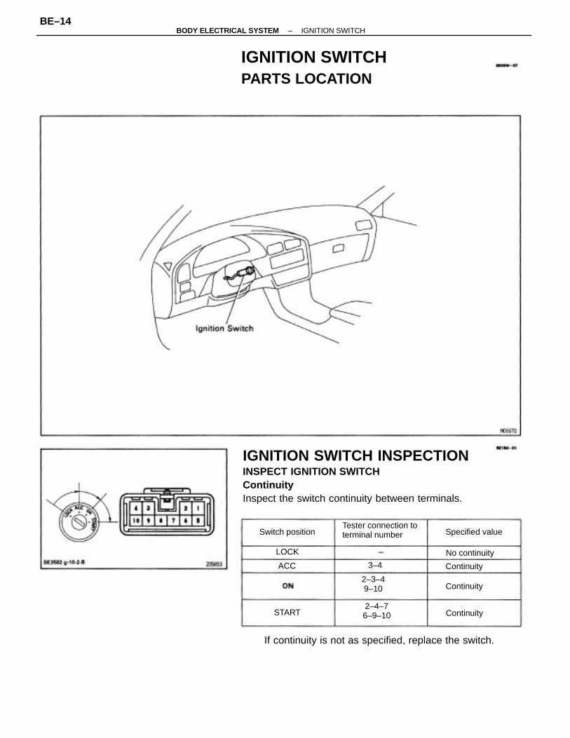
IGNITION SWITCH INSPECTIONINSPECT IGNITION SWITCHContinuityInspect the switch continuity between terminals.
IGNITION SWITCHPARTS LOCATION
If continuity is not as specified, replace the switch.
Tester connection toterminal number
2–4–76–9–10
2–3–49–10
Specified valueSwitch position
No continuity
Continuity
Continuity
Continuity3–4
START
LOCK
ACC
–BODY ELECTRICAL SYSTEM IGNITION SWITCHBE–14
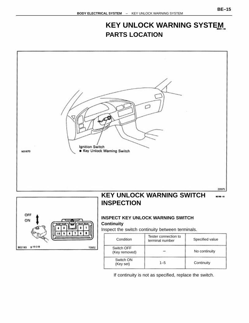
KEY UNLOCK WARNING SWITCHINSPECTION
INSPECT KEY UNLOCK WARNING SWITCHContinuityInspect the switch continuity between terminals.
KEY UNLOCK WARNING SYSTEMPARTS LOCATION
If continuity is not as specified, replace the switch.
Tester connection toterminal number
Switch OFF(Key removed)
Switch ON(Key set)
Specified value
No continuity
Continuity
Condition
1–5
–BODY ELECTRICAL SYSTEM KEY UNLOCK WARNING SYSTEMBE–15
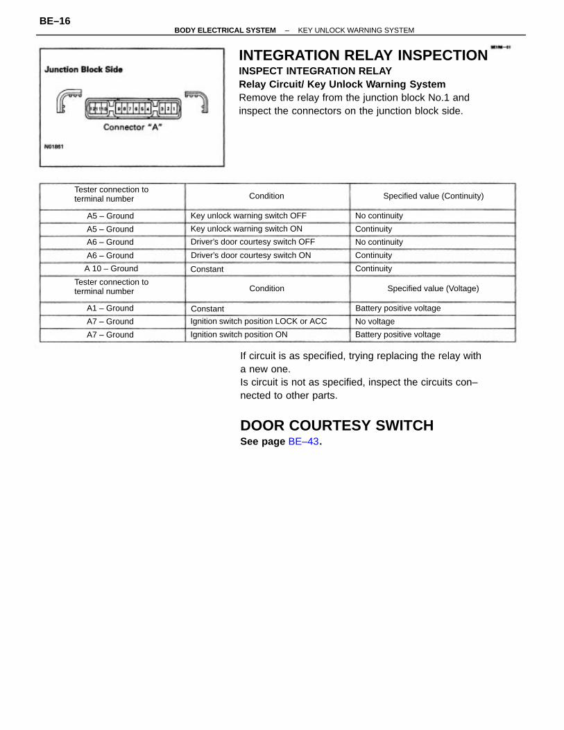
If circuit is as specified, trying replacing the relay witha new one.Is circuit is not as specified, inspect the circuits con–nected to other parts.
DOOR COURTESY SWITCHSee page BE–43.
INTEGRATION RELAY INSPECTIONINSPECT INTEGRATION RELAYRelay Circuit/ Key Unlock Warning SystemRemove the relay from the junction block No.1 andinspect the connectors on the junction block side.
Ignition switch position LOCK or ACC
Tester connection toterminal number
Tester connection toterminal number
Driver’s door courtesy switch OFF
Driver’s door courtesy switch ON
Key unlock warning switch OFF
Key unlock warning switch ON
Ignition switch position ON
Specified value (Continuity)
Specified value (Voltage)
Battery positive voltage
Battery positive voltage
A 10 – Ground
A1 – Ground
No continuity
No continuity
A6 – Ground
A6 – Ground
A7 – Ground
A5 – Ground
A7 – Ground
A5 – Ground
No voltage
Continuity
Continuity
Continuity
Condition
Condition
Constant
Constant
–BODY ELECTRICAL SYSTEM KEY UNLOCK WARNING SYSTEMBE–16
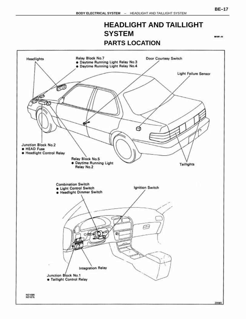
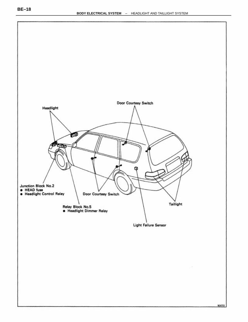
HEADLIGHT AND TAILLIGHTSYSTEMPARTS LOCATION
–BODY ELECTRICAL SYSTEM HEADLIGHT AND TAILLIGHT SYSTEMBE–17
–BODY ELECTRICAL SYSTEM HEADLIGHT AND TAILLIGHT SYSTEMBE–18
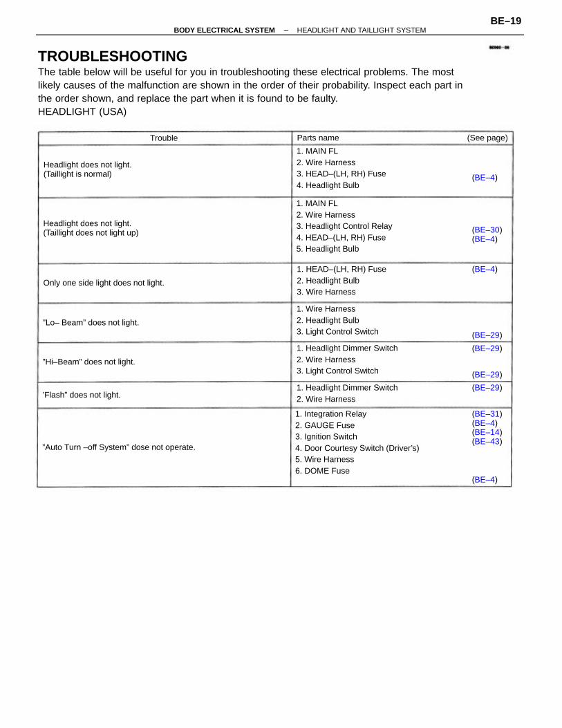
TROUBLESHOOTINGThe table below will be useful for you in troubleshooting these electrical problems. The mostlikely causes of the malfunction are shown in the order of their probability. Inspect each part inthe order shown, and replace the part when it is found to be faulty.HEADLIGHT (USA)
1. Integration Relay2. GAUGE Fuse3. Ignition Switch4. Door Courtesy Switch (Driver’s)5. Wire Harness6. DOME Fuse
1. MAIN FL2. Wire Harness3. Headlight Control Relay4. HEAD–(LH, RH) Fuse5. Headlight Bulb
1. MAIN FL2. Wire Harness3. HEAD–(LH, RH) Fuse4. Headlight Bulb
1. Headlight Dimmer Switch2. Wire Harness3. Light Control Switch
1. HEAD–(LH, RH) Fuse2. Headlight Bulb3. Wire Harness
1. Wire Harness2. Headlight Bulb3. Light Control Switch
Headlight does not light.(Taillight does not light up)
1. Headlight Dimmer Switch2. Wire Harness
Headlight does not light.(Taillight is normal)
”Auto Turn –off System” dose not operate.
(BE–31)(BE–4)(BE–14)(BE–43)
Only one side light does not light.
”Lo– Beam” does not light.
”Hi–Beam” does not light.
’Flash” does not light.
(BE–30)(BE–4)
(See page)Parts name
(BE–29)
(BE–29)
(BE–29)
(BE–29)
(BE–4)
(BE–4)
(BE–4)
Trouble
–BODY ELECTRICAL SYSTEM HEADLIGHT AND TAILLIGHT SYSTEMBE–19
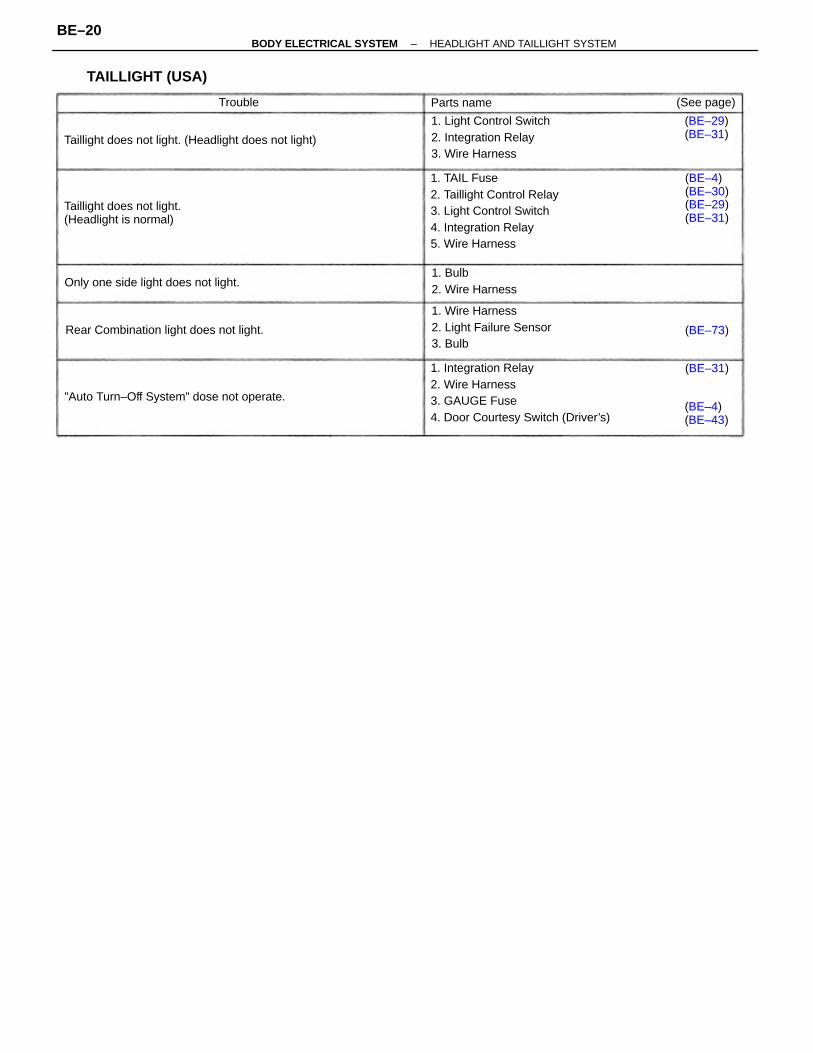
1. Integration Relay2. Wire Harness3. GAUGE Fuse4. Door Courtesy Switch (Driver’s)
1. TAIL Fuse2. Taillight Control Relay3. Light Control Switch4. Integration Relay5. Wire Harness
1. Light Control Switch2. Integration Relay3. Wire Harness
1. Wire Harness2. Light Failure Sensor3. Bulb
Taillight does not light. (Headlight does not light)
”Auto Turn–Off System” dose not operate.
Taillight does not light.(Headlight is normal)
Rear Combination light does not light.
(BE–4)(BE–30)(BE–29)(BE–31)
Only one side light does not light.1. Bulb2. Wire Harness
TAILLIGHT (USA)
(BE–4)(BE–43)
(BE–29)(BE–31)
(See page)Parts name
(BE–31)
(BE–73)
Trouble
–BODY ELECTRICAL SYSTEM HEADLIGHT AND TAILLIGHT SYSTEMBE–20
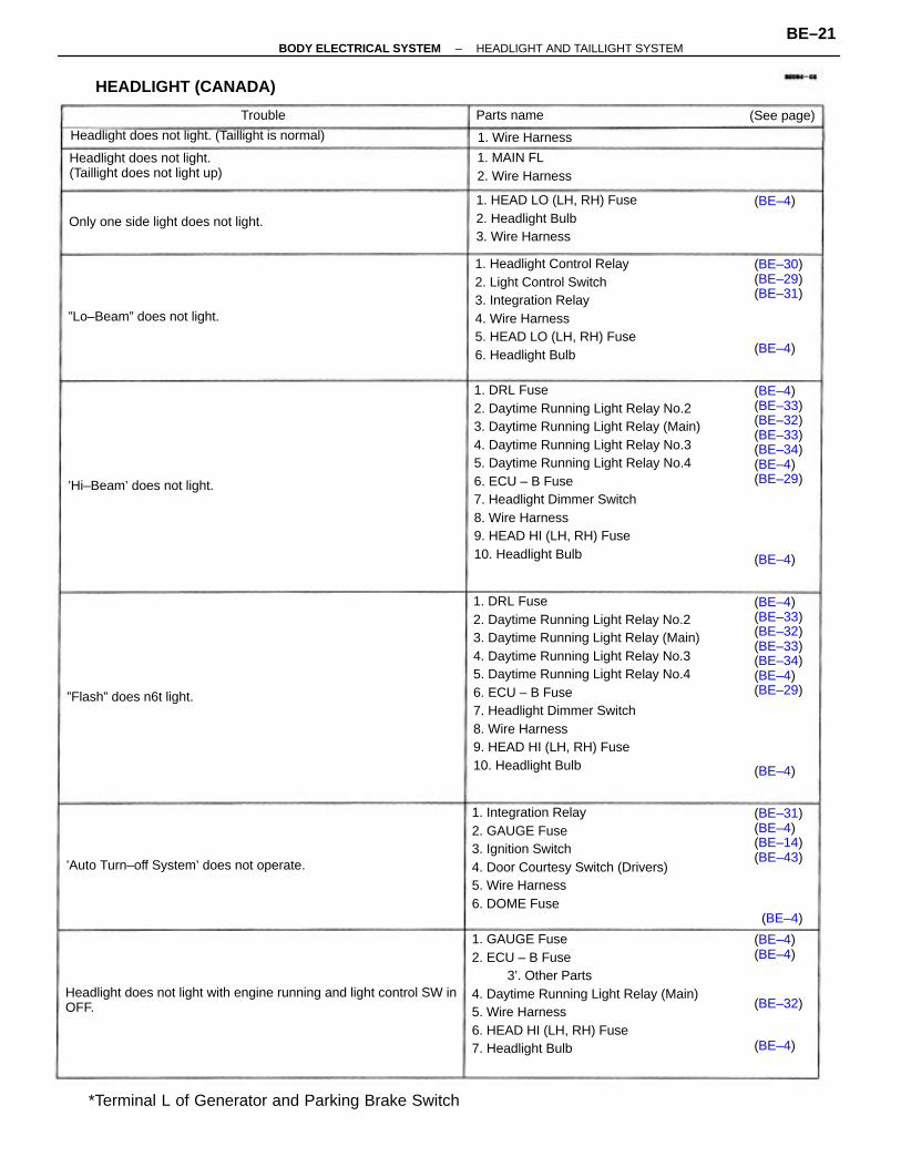
1. DRL Fuse2. Daytime Running Light Relay No.23. Daytime Running Light Relay (Main)4. Daytime Running Light Relay No.35. Daytime Running Light Relay No.46. ECU – B Fuse7. Headlight Dimmer Switch8. Wire Harness9. HEAD HI (LH, RH) Fuse10. Headlight Bulb
1. DRL Fuse2. Daytime Running Light Relay No.23. Daytime Running Light Relay (Main)4. Daytime Running Light Relay No.35. Daytime Running Light Relay No.46. ECU – B Fuse7. Headlight Dimmer Switch8. Wire Harness9. HEAD HI (LH, RH) Fuse10. Headlight Bulb
1. GAUGE Fuse2. ECU – B Fuse
3’. Other Parts4. Daytime Running Light Relay (Main)5. Wire Harness6. HEAD HI (LH, RH) Fuse7. Headlight Bulb
1. Integration Relay2. GAUGE Fuse3. Ignition Switch4. Door Courtesy Switch (Drivers)5. Wire Harness6. DOME Fuse
1. Headlight Control Relay2. Light Control Switch3. Integration Relay4. Wire Harness5. HEAD LO (LH, RH) Fuse6. Headlight Bulb
Headlight does not light with engine running and light control SW inOFF.
*Terminal L of Generator and Parking Brake Switch
1. HEAD LO (LH, RH) Fuse2. Headlight Bulb3. Wire Harness
(BE–4)(BE–33)(BE–32)(BE–33)(BE–34)(BE–4)(BE–29)
(BE–4)(BE–33)(BE–32)(BE–33)(BE–34)(BE–4)(BE–29)
Headlight does not light.(Taillight does not light up)
Headlight does not light. (Taillight is normal)
’Auto Turn–off System’ does not operate.
HEADLIGHT (CANADA)
(BE–31)(BE–4)(BE–14)(BE–43)
Only one side light does not light.
1. MAIN FL2. Wire Harness
”Lo–Beam” does not light.
(BE–30)(BE–29)(BE–31)
’Hi–Beam’ does not light.
”Flash” does n6t light.
(BE–4)(BE–4)
1. Wire Harness
Parts name (See page)
(BE–32)
(BE–4)
(BE–4)
(BE–4)
(BE–4)
(BE–4)
(BE–4)
Trouble
–BODY ELECTRICAL SYSTEM HEADLIGHT AND TAILLIGHT SYSTEMBE–21
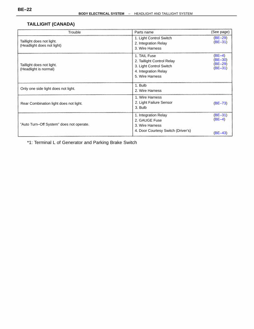
1. Integration Relay2. GAUGE Fuse3. Wire Harness4. Door Courtesy Switch (Driver’s)
1. TAIL Fuse2. Taillight Control Relay3. Light Control Switch4. Integration Relay5. Wire Harness
*1: Terminal L of Generator and Parking Brake Switch
1. Light Control Switch2. Integration Relay3. Wire Harness
1. Wire Harness2. Light Failure Sensor3. Bulb
Taillight does not light.(Headlight does not light)
”Auto Turn–Off System” does not operate.
Taillight does not light.(Headlight is normal)
Rear Combination light does not light.
TAILLIGHT (CANADA)
(BE–4)(BE–30)(BE–29)(BE–31)
Only one side light does not light.1. Bulb2. Wire Harness
(BE–29)(BE–31)
(BE–31)(BE–4)
(See page)Parts name
(BE–43)
(BE–73)
Trouble
–BODY ELECTRICAL SYSTEM HEADLIGHT AND TAILLIGHT SYSTEMBE–22
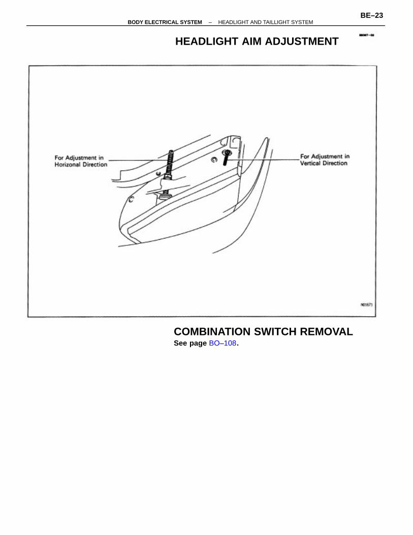
COMBINATION SWITCH REMOVALSee page BO–108.
HEADLIGHT AIM ADJUSTMENT
–BODY ELECTRICAL SYSTEM HEADLIGHT AND TAILLIGHT SYSTEMBE–23
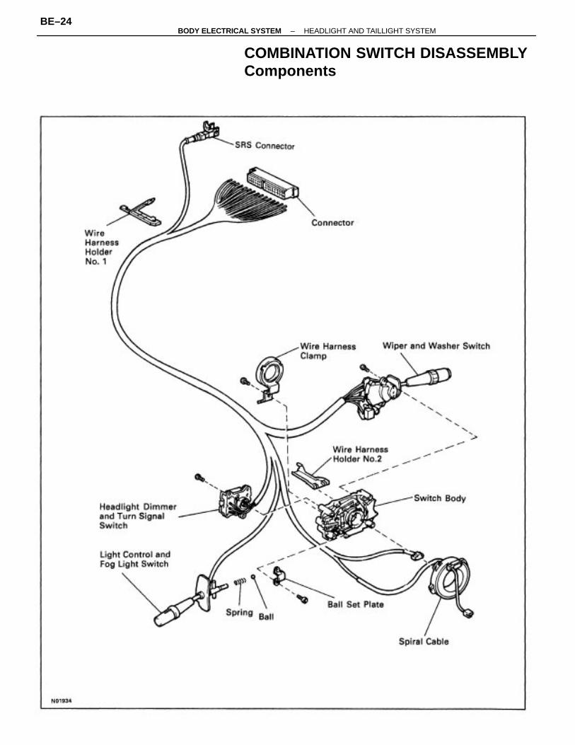
COMBINATION SWITCH DISASSEMBLYComponents
–BODY ELECTRICAL SYSTEM HEADLIGHT AND TAILLIGHT SYSTEMBE–24
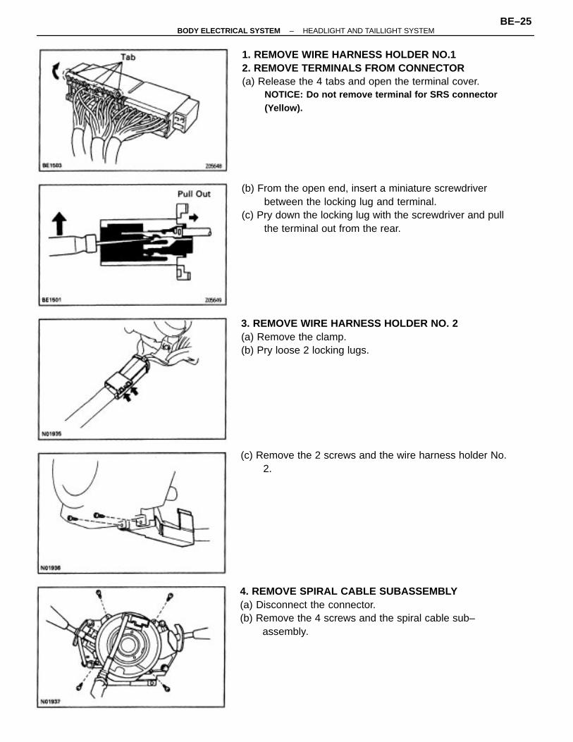
1. REMOVE WIRE HARNESS HOLDER NO.12. REMOVE TERMINALS FROM CONNECTOR(a) Release the 4 tabs and open the terminal cover.
NOTICE: Do not remove terminal for SRS connector(Yellow).
4. REMOVE SPIRAL CABLE SUBASSEMBLY(a) Disconnect the connector.(b) Remove the 4 screws and the spiral cable sub–
assembly.
(b) From the open end, insert a miniature screwdriverbetween the locking lug and terminal.
(c) Pry down the locking lug with the screwdriver and pullthe terminal out from the rear.
3. REMOVE WIRE HARNESS HOLDER NO. 2(a) Remove the clamp.(b) Pry loose 2 locking lugs.
(c) Remove the 2 screws and the wire harness holder No.2.
–BODY ELECTRICAL SYSTEM HEADLIGHT AND TAILLIGHT SYSTEMBE–25
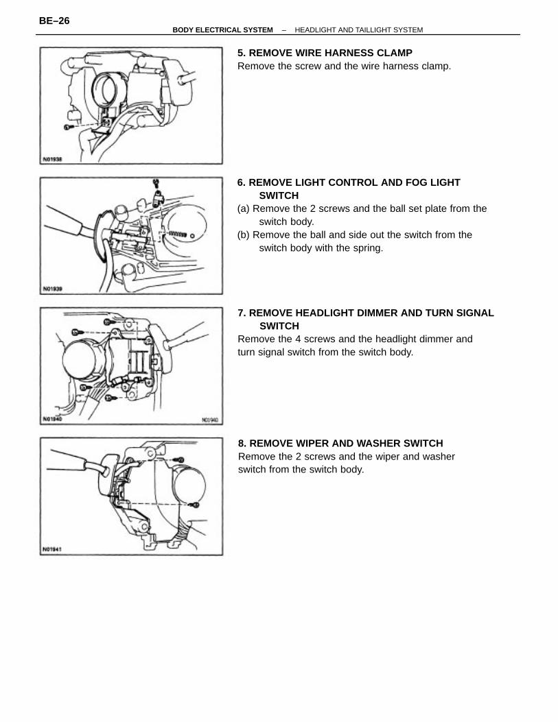
6. REMOVE LIGHT CONTROL AND FOG LIGHTSWITCH
(a) Remove the 2 screws and the ball set plate from theswitch body.
(b) Remove the ball and side out the switch from theswitch body with the spring.
7. REMOVE HEADLIGHT DIMMER AND TURN SIGNALSWITCH
Remove the 4 screws and the headlight dimmer andturn signal switch from the switch body.
8. REMOVE WIPER AND WASHER SWITCHRemove the 2 screws and the wiper and washerswitch from the switch body.
5. REMOVE WIRE HARNESS CLAMPRemove the screw and the wire harness clamp.
–BODY ELECTRICAL SYSTEM HEADLIGHT AND TAILLIGHT SYSTEMBE–26
COMBINATION SWITCH ASSEMBLY
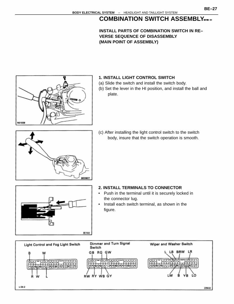
INSTALL PARTS OF COMBINATION SWITCH IN RE–VERSE SEQUENCE OF DISASSEMBLY(MAIN POINT OF ASSEMBLY)
2. INSTALL TERMINALS TO CONNECTOR• Push in the terminal until it is securely locked in
the connector lug.• Install each switch terminal, as shown in the
figure.
1. INSTALL LIGHT CONTROL SWITCH(a) Slide the switch and install the switch body.(b) Set the lever in the HI position, and install the ball and
plate.
(c) After installing the light control switch to the switchbody, insure that the switch operation is smooth.
–BODY ELECTRICAL SYSTEM HEADLIGHT AND TAILLIGHT SYSTEMBE–27
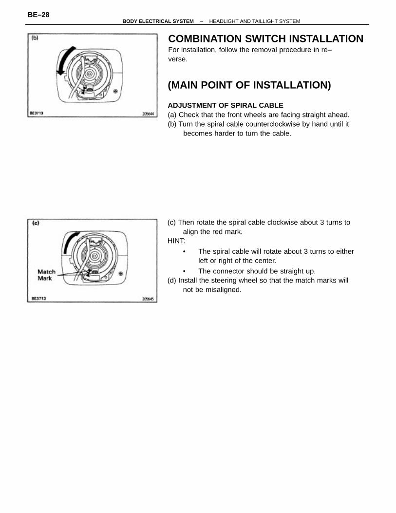
(c) Then rotate the spiral cable clockwise about 3 turns toalign the red mark.
HINT:
• The spiral cable will rotate about 3 turns to eitherleft or right of the center.
• The connector should be straight up.(d) Install the steering wheel so that the match marks will
not be misaligned.
(MAIN POINT OF INSTALLATION)
ADJUSTMENT OF SPIRAL CABLE(a) Check that the front wheels are facing straight ahead.(b) Turn the spiral cable counterclockwise by hand until it
becomes harder to turn the cable.
COMBINATION SWITCH INSTALLATIONFor installation, follow the removal procedure in re–verse.
–BODY ELECTRICAL SYSTEM HEADLIGHT AND TAILLIGHT SYSTEMBE–28
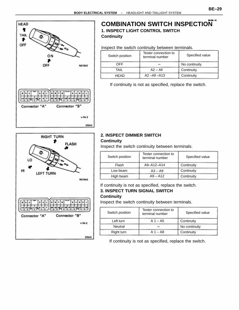
COMBINATION SWITCH INSPECTION1. INSPECT LIGHT CONTROL SWITCHContinuity
Inspect the switch continuity between terminals.
If continuity is not as specified, replace the switch.3. INSPECT TURN SIGNAL SWITCHContinuityInspect the switch continuity between terminals.
2. INSPECT DIMMER SWITCHContinuityInspect the switch continuity between terminals.
If continuity is not as specified, replace the switch.
If continuity is not as specified, replace the switch.
Tester connection toterminal number
Tester connection toterminal number
Tester connection toterminal number
A9–A12–A14
A2 –All –A13
Specified value
Switch position Specified value
Switch position
Switch position Specified value
No continuity
No continuity
High beam
Continuity
ContinuityRight turn
Continuity
A9 – A12 Continuity
A2 – All
Continuity
Continuity
Continuity
Low beam
A 1 – A8
A 1 – A5Left turn
A3 – A9
Neutral
HEAD
Flash
TAIL
OFF
–BODY ELECTRICAL SYSTEM HEADLIGHT AND TAILLIGHT SYSTEMBE–29
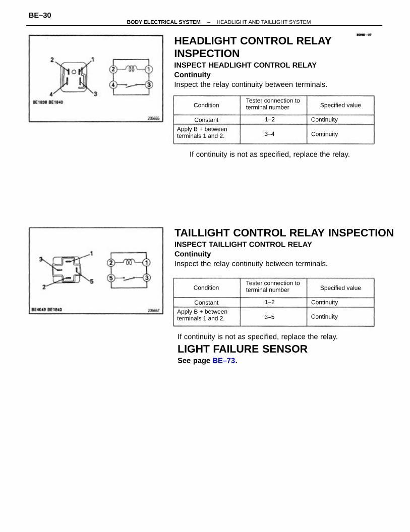
HEADLIGHT CONTROL RELAYINSPECTIONINSPECT HEADLIGHT CONTROL RELAYContinuityInspect the relay continuity between terminals.
TAILLIGHT CONTROL RELAY INSPECTIONINSPECT TAILLIGHT CONTROL RELAYContinuityInspect the relay continuity between terminals.
If continuity is not as specified, replace the relay.
LIGHT FAILURE SENSORSee page BE–73.
If continuity is not as specified, replace the relay.
Tester connection toterminal number
Tester connection toterminal number
Apply B + betweenterminals 1 and 2.
Apply B + betweenterminals 1 and 2.
Specified value
Specified value
Continuity
Continuity
Continuity
Continuity
Condition
Condition
Constant
Constant
3–4
1–2
1–2
3–5
–BODY ELECTRICAL SYSTEM HEADLIGHT AND TAILLIGHT SYSTEMBE–30
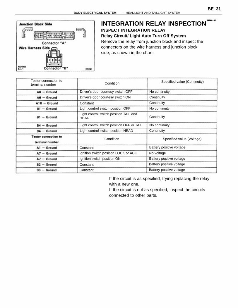
INTEGRATION RELAY INSPECTIONINSPECT INTEGRATION RELAYRelay Circuit/ Light Auto Turn Off SystemRemove the relay from junction block and inspect theconnectors on the wire harness and junction blockside, as shown in the chart.
If the circuit is as specified, trying replacing the relaywith a new one.If the circuit is not as specified, inspect the circuitsconnected to other parts.
Light control switch position TAIL andHEAD
Light control switch position OFF or TAIL
Ignition switch position LOCK or ACC
Tester connection toterminal number
Light control switch position HEAD
Specified value (Continuity)
Driver’s door courtesy switch OFF
Light control switch position OFF
Driver’s door courtesy switch ON
Ignition switch position ON
Specified value (Voltage)
Battery positive voltage
Battery positive voltage
Battery positive voltage
Battery positive voltage
No continuity
No continuity
No continuity
No voltage
Continuity
Continuity
Continuity
Continuity
Condition
Condition
Constant
Constant
Constant
Constant
–BODY ELECTRICAL SYSTEM HEADLIGHT AND TAILLIGHT SYSTEMBE–31
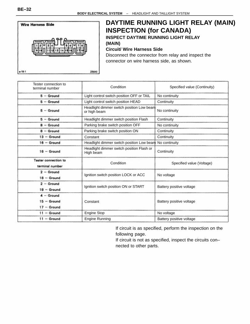
DAYTIME RUNNING LIGHT RELAY (MAIN)INSPECTION (for CANADA)INSPECT DAYTIME RUNNING LIGHT RELAY(MAIN)Circuit/ Wire Harness SideDisconnect the connector from relay and inspect theconnector on wire harness side, as shown.
If circuit is as specified, perform the inspection on thefollowing page.If circuit is not as specified, inspect the circuits con–nected to other parts.
Headlight dimmer switch position Low beamor high beam
Headlight dimmer switch position Flash orHigh beam
Headlight dimmer switch position Low beam
Light control switch position OFF or TAIL
Headlight dimmer switch position Flash
Ignition switch position ON or START
Ignition switch position LOCK or ACC
Tester connection toterminal number
Light control switch position HEAD
Parking brake switch position OFF
Parking brake switch position ON
Specified value (Continuity)
Specified value (Voltage)
Battery positive voltage
Battery positive voltage
Battery positive voltage
Engine Running
No continuity
No continuity
No continuity
No continuity
Engine Stop No voltage
No voltage
Continuity
Continuity
Continuity
Continuity
Continuity
Condition
Condition
Constant
Constant
–BODY ELECTRICAL SYSTEM HEADLIGHT AND TAILLIGHT SYSTEMBE–32
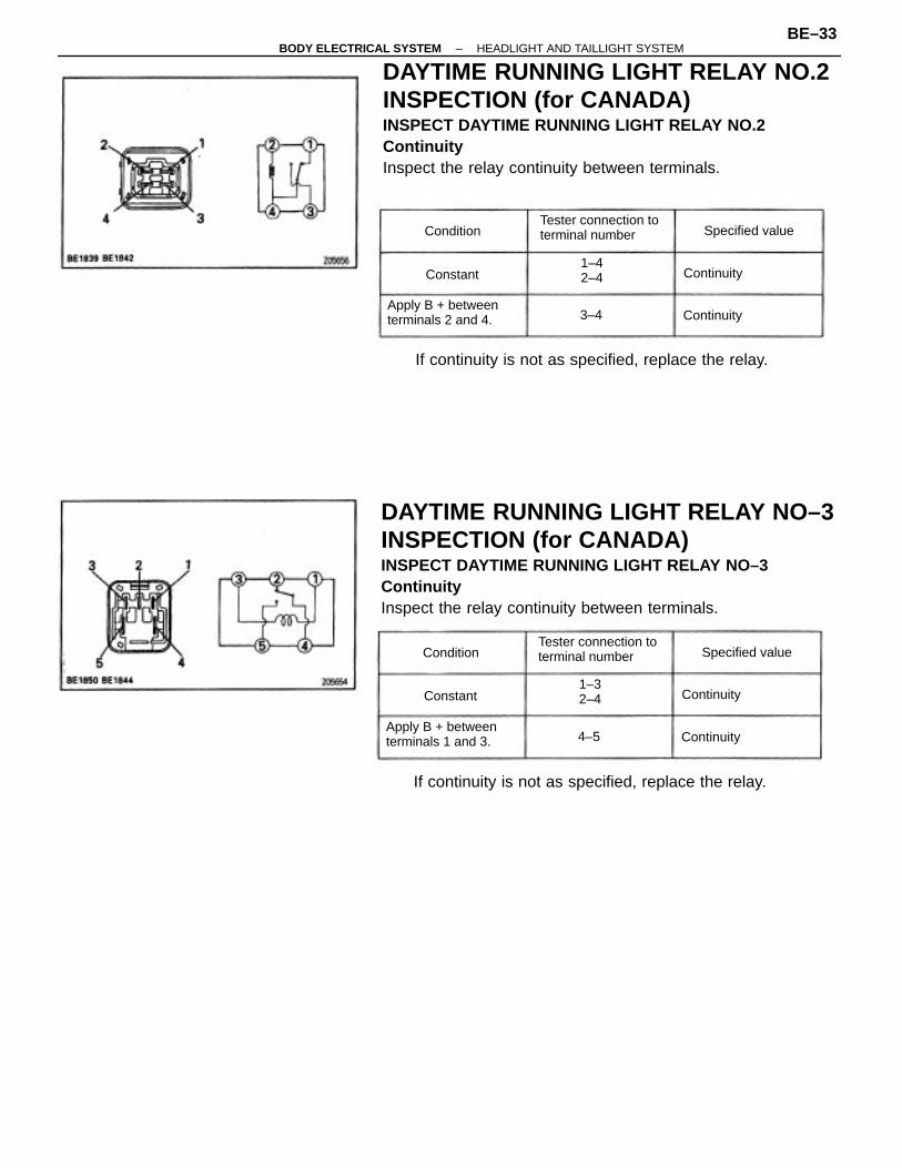
DAYTIME RUNNING LIGHT RELAY NO.2INSPECTION (for CANADA)INSPECT DAYTIME RUNNING LIGHT RELAY NO.2ContinuityInspect the relay continuity between terminals.
DAYTIME RUNNING LIGHT RELAY NO–3INSPECTION (for CANADA)INSPECT DAYTIME RUNNING LIGHT RELAY NO–3ContinuityInspect the relay continuity between terminals.
If continuity is not as specified, replace the relay.
If continuity is not as specified, replace the relay.
Tester connection toterminal number
Tester connection toterminal number
Apply B + betweenterminals 1 and 3.
Apply B + betweenterminals 2 and 4.
Specified value
Specified value
1–32–4
1–42–4 Continuity
Continuity
Continuity
Continuity
Condition
Condition
Constant
Constant
3–4
4–5
–BODY ELECTRICAL SYSTEM HEADLIGHT AND TAILLIGHT SYSTEMBE–33
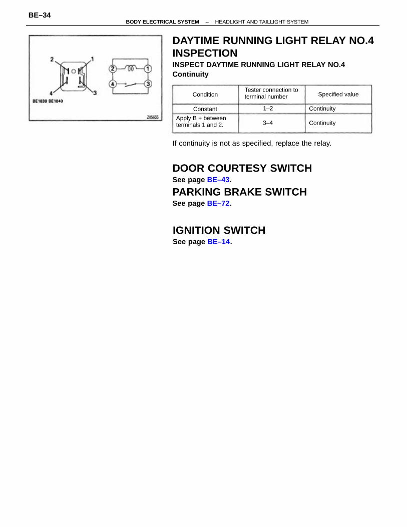
If continuity is not as specified, replace the relay.
DOOR COURTESY SWITCHSee page BE–43.
PARKING BRAKE SWITCHSee page BE–72.
DAYTIME RUNNING LIGHT RELAY NO.4INSPECTIONINSPECT DAYTIME RUNNING LIGHT RELAY NO.4Continuity
IGNITION SWITCHSee page BE–14.
Tester connection toterminal number
Apply B + betweenterminals 1 and 2.
Specified value
Continuity
Continuity
Condition
Constant
3–4
1–2
–BODY ELECTRICAL SYSTEM HEADLIGHT AND TAILLIGHT SYSTEMBE–34
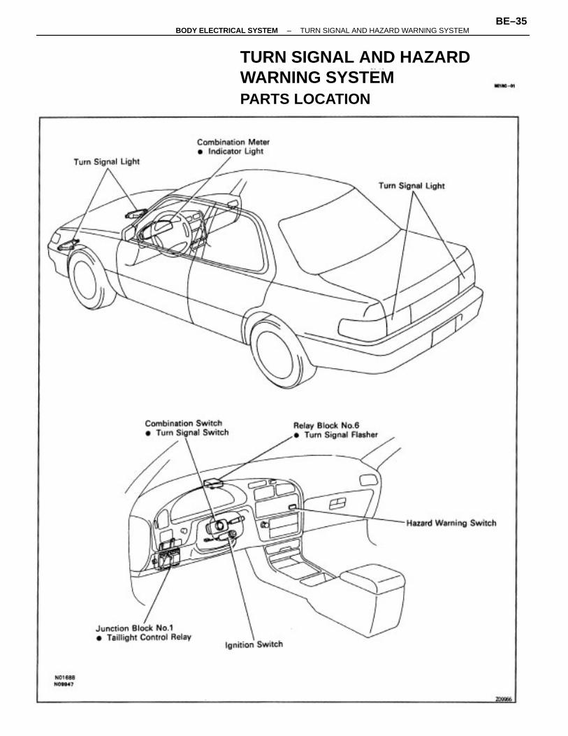
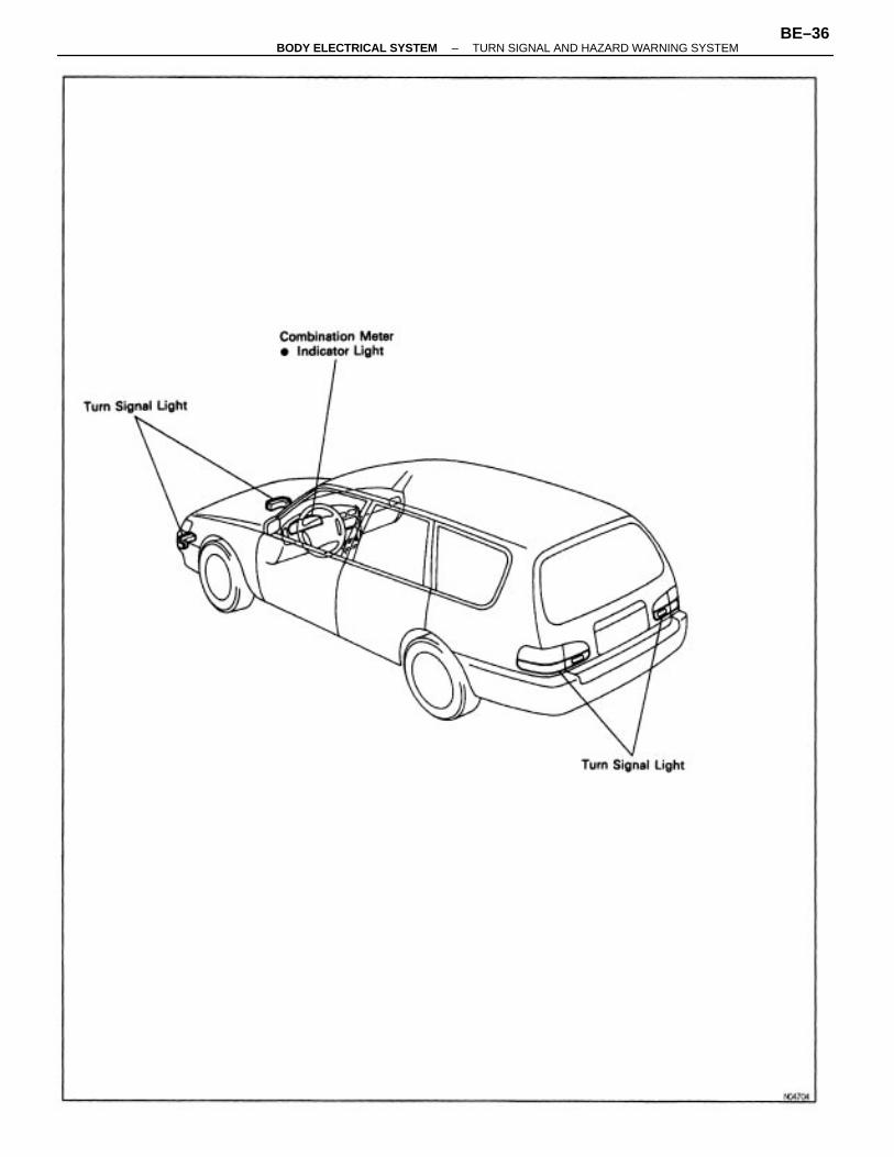
TURN SIGNAL AND HAZARDWARNING SYSTEMPARTS LOCATION
–BODY ELECTRICAL SYSTEM TURN SIGNAL AND HAZARD WARNING SYSTEMBE–35
–BODY ELECTRICAL SYSTEM TURN SIGNAL AND HAZARD WARNING SYSTEMBE–36
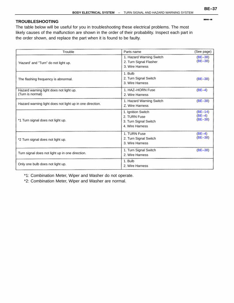
TROUBLESHOOTINGThe table below will be useful for you in troubleshooting these electrical problems. The mostlikely causes of the malfunction are shown in the order of their probability. Inspect each part inthe order shown, and replace the part when it is found to be faulty.
*1: Combination Meter, Wiper and Washer do not operate.*2: Combination Meter, Wiper and Washer are normal.
1. Ignition Switch2. TURN Fuse3. Turn Signal Switch4. Wire Harness
Hazard warning light does not light up.(Turn is normal)
1. Hazard Warning Switch2. Turn Signal Flasher3. Wire Harness
1. Bulb2. Turn Signal Switch3. Wire Harness
1. TURN Fuse2. Turn Signal Switch3. Wire Harness
Hazard warning light does not light up in one direction.
Turn signal does not light up in one direction.
1. Hazard Warning SwitchZ. Wire Harness
1. Turn Signal Switch2. Wire Harness
1. HAZ–HORN Fuse2. Wire Harness
The flashing frequency is abnormal.
’Hazard’ and ”Turn” do not light up.
Only one bulb does not light up.
*2 Turn signal does not light up.
*1 Turn signal does not light up.
1. Bulb2. Wire Harness
(BE–14)(BE–4)(BE–38)
(BE–4)(BE–38)
(BE–38)(BE–38)
(See page)Parts name
(BE–38)
(BE–38)
(BE–38)
(BE–4)
Trouble
–BODY ELECTRICAL SYSTEM TURN SIGNAL AND HAZARD WARNING SYSTEMBE–37
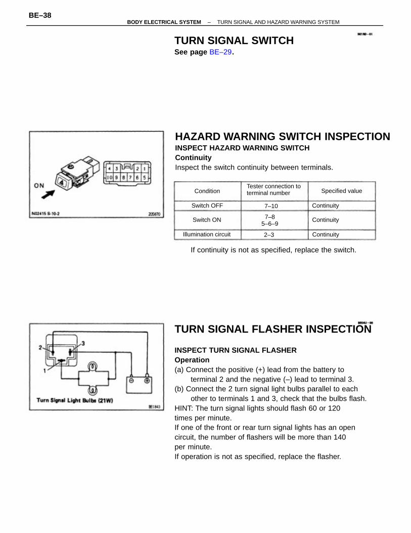
TURN SIGNAL FLASHER INSPECTION
INSPECT TURN SIGNAL FLASHEROperation(a) Connect the positive (+) lead from the battery to
terminal 2 and the negative (–) lead to terminal 3.(b) Connect the 2 turn signal light bulbs parallel to each
other to terminals 1 and 3, check that the bulbs flash.HINT: The turn signal lights should flash 60 or 120times per minute.If one of the front or rear turn signal lights has an opencircuit, the number of flashers will be more than 140per minute.If operation is not as specified, replace the flasher.
HAZARD WARNING SWITCH INSPECTIONINSPECT HAZARD WARNING SWITCHContinuityInspect the switch continuity between terminals.
TURN SIGNAL SWITCHSee page BE–29.
If continuity is not as specified, replace the switch.
Tester connection toterminal number
7–85–6–9
Illumination circuit
Specified value
Switch OFF
Switch ON Continuity
Continuity
Continuity
Condition
7–10
2–3
–BODY ELECTRICAL SYSTEM TURN SIGNAL AND HAZARD WARNING SYSTEMBE–38
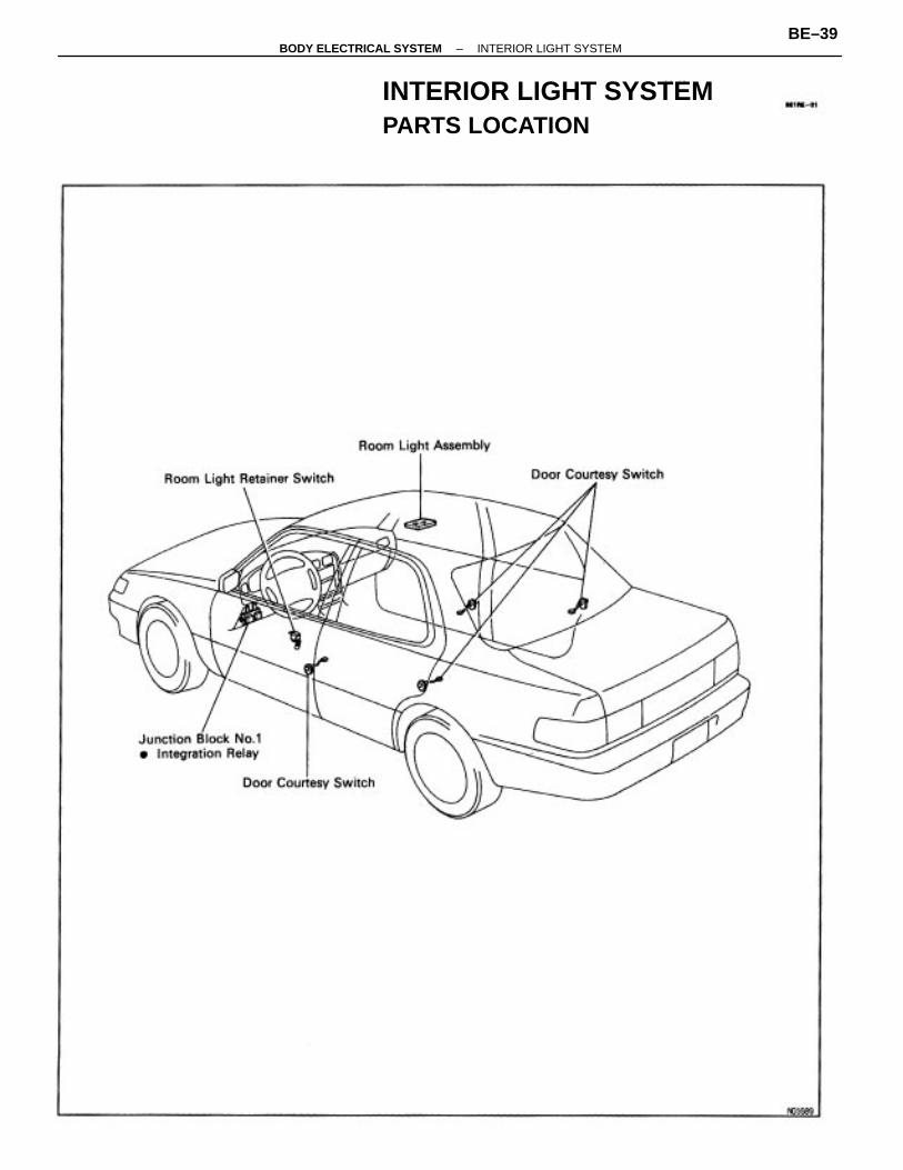
INTERIOR LIGHT SYSTEMPARTS LOCATION
–BODY ELECTRICAL SYSTEM INTERIOR LIGHT SYSTEMBE–39
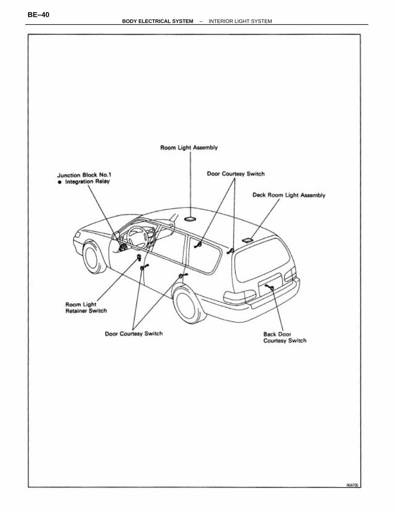
–BODY ELECTRICAL SYSTEM INTERIOR LIGHT SYSTEMBE–40
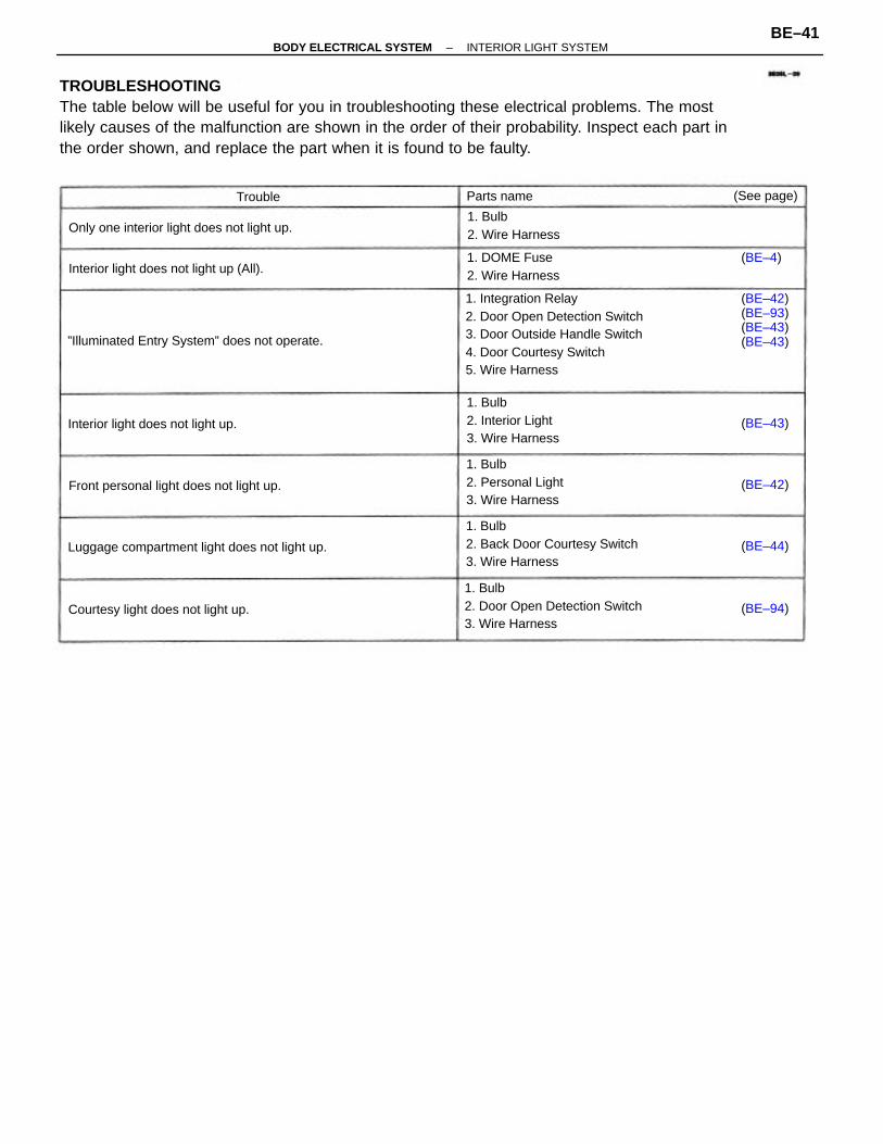
TROUBLESHOOTINGThe table below will be useful for you in troubleshooting these electrical problems. The mostlikely causes of the malfunction are shown in the order of their probability. Inspect each part inthe order shown, and replace the part when it is found to be faulty.
1. Integration Relay2. Door Open Detection Switch3. Door Outside Handle Switch4. Door Courtesy Switch5. Wire Harness
1. Bulb2. Door Open Detection Switch3. Wire Harness
1. Bulb2. Back Door Courtesy Switch3. Wire Harness
”Illuminated Entry System” does not operate.
Front personal light does not light up.
Luggage compartment light does not light up.
Interior light does not light up.
1. Bulb2. Personal Light3. Wire Harness
1. Bulb2. Interior Light3. Wire Harness
Only one interior light does not light up.
(BE–42)(BE–93)(BE–43)(BE–43)
Interior light does not light up (All).
Courtesy light does not light up.
1. Bulb2. Wire Harness
1. DOME Fuse2. Wire Harness
(See page)Parts name
(BE–94)
(BE–44)
(BE–43)
(BE–42)
(BE–4)
Trouble
–BODY ELECTRICAL SYSTEM INTERIOR LIGHT SYSTEMBE–41
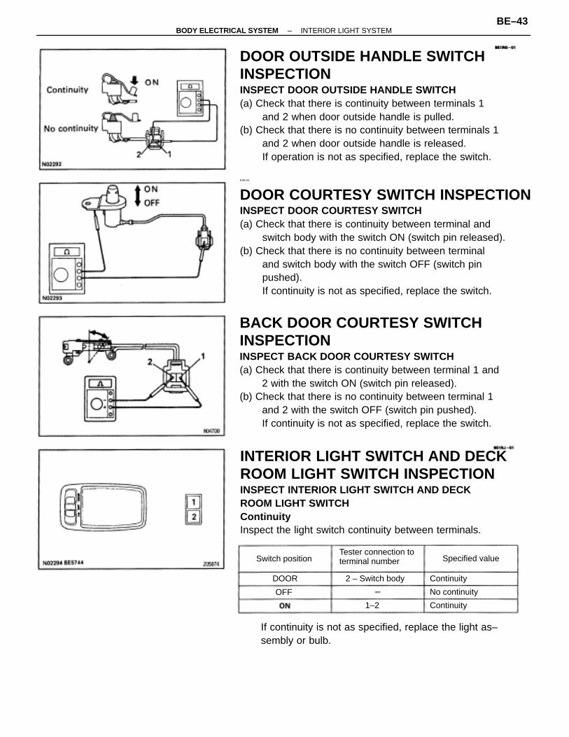
INTEGRATION RELAY INSPECTION
INSPECT INTEGRATION RELAYRelay Circuit/ Illuminated Entry SystemRemove the relay from junction block and inspect theconnector on the junction block side, as shown in thechart.
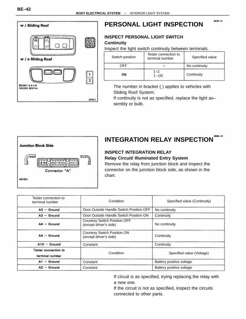
PERSONAL LIGHT INSPECTION
INSPECT PERSONAL LIGHT SWITCHContinuityInspect the light switch continuity between terminals.
The number in bracket ( ) applies to vehicles withSliding Roof System.If continuity is not as specified, replace the light as–sembly or bulb.
If circuit is as specified, trying replacing the relay witha new one.If the circuit is not as specified, inspect the circuitsconnected to other parts.
Courtesy Switch Position OFF(except driver’s side)
Courtesy Switch Position ON(except driver’s side)
Door Outside Handle Switch Position OFF
Door Outside Handle Switch Position ON
Tester connection toterminal number
Tester connection toterminal number
Specified value (Continuity)
Specified value (Voltage)
Battery positive voltage
Battery positive voltage
1–21 –(4)
Specified valueSwitch position
No continuity
No continuity
No continuity
Continuity
Continuity
Continuity
Continuity
Condition
Condition
Constant
Constant
Constant
OFF
–BODY ELECTRICAL SYSTEM INTERIOR LIGHT SYSTEMBE–42
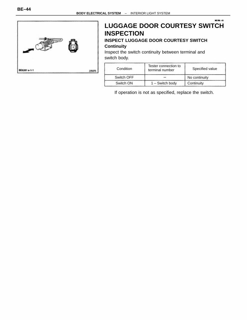
DOOR OUTSIDE HANDLE SWITCHINSPECTIONINSPECT DOOR OUTSIDE HANDLE SWITCH(a) Check that there is continuity between terminals 1
and 2 when door outside handle is pulled.(b) Check that there is no continuity between terminals 1
and 2 when door outside handle is released.If operation is not as specified, replace the switch.
KIM–01
DOOR COURTESY SWITCH INSPECTIONINSPECT DOOR COURTESY SWITCH(a) Check that there is continuity between terminal and
switch body with the switch ON (switch pin released).(b) Check that there is no continuity between terminal
and switch body with the switch OFF (switch pinpushed).If continuity is not as specified, replace the switch.
BACK DOOR COURTESY SWITCHINSPECTIONINSPECT BACK DOOR COURTESY SWITCH(a) Check that there is continuity between terminal 1 and
2 with the switch ON (switch pin released).(b) Check that there is no continuity between terminal 1
and 2 with the switch OFF (switch pin pushed).If continuity is not as specified, replace the switch.
INTERIOR LIGHT SWITCH AND DECKROOM LIGHT SWITCH INSPECTIONINSPECT INTERIOR LIGHT SWITCH AND DECKROOM LIGHT SWITCHContinuityInspect the light switch continuity between terminals.
If continuity is not as specified, replace the light as–sembly or bulb.
Tester connection toterminal number
2 – Switch body
Specified valueSwitch position
No continuity
Continuity
Continuity1–2
DOOR
OFF
–BODY ELECTRICAL SYSTEM INTERIOR LIGHT SYSTEMBE–43
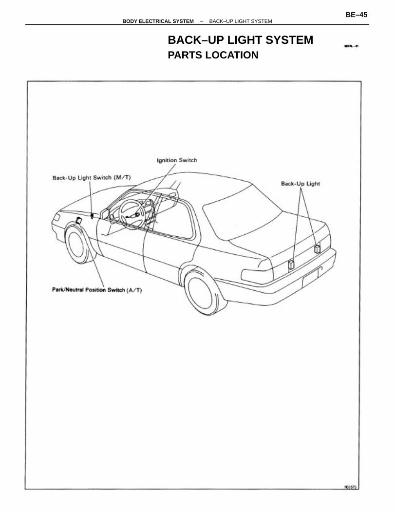
LUGGAGE DOOR COURTESY SWITCHINSPECTIONINSPECT LUGGAGE DOOR COURTESY SWITCHContinuityInspect the switch continuity between terminal andswitch body.
If operation is not as specified, replace the switch.
Tester connection toterminal number
1 – Switch body
Specified value
No continuitySwitch OFF
ContinuitySwitch ON
Condition
–BODY ELECTRICAL SYSTEM INTERIOR LIGHT SYSTEMBE–44
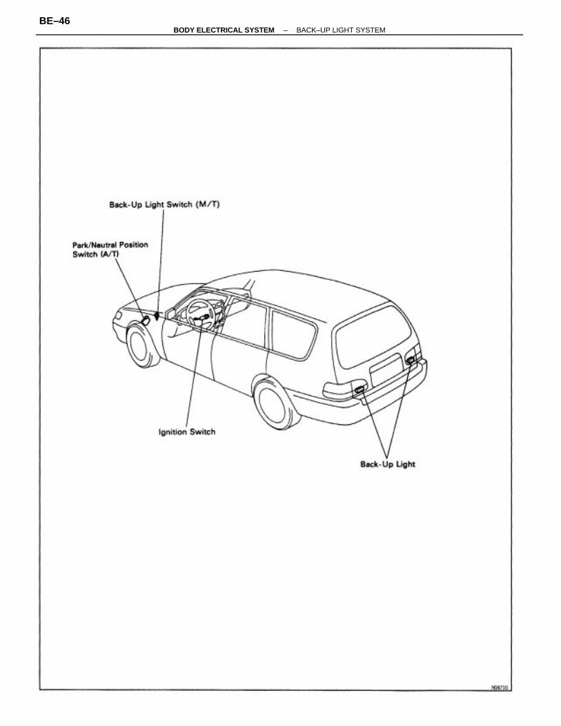
BACK–UP LIGHT SYSTEMPARTS LOCATION
–BODY ELECTRICAL SYSTEM BACK–UP LIGHT SYSTEMBE–45
–BODY ELECTRICAL SYSTEM BACK–UP LIGHT SYSTEMBE–46
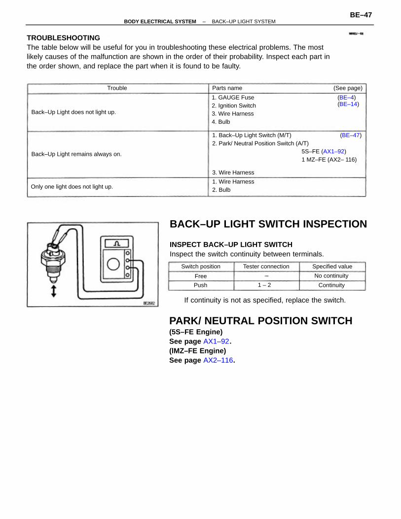
TROUBLESHOOTINGThe table below will be useful for you in troubleshooting these electrical problems. The mostlikely causes of the malfunction are shown in the order of their probability. Inspect each part inthe order shown, and replace the part when it is found to be faulty.
PARK/ NEUTRAL POSITION SWITCH(5S–FE Engine)See page AX1–92.(lMZ–FE Engine)See page AX2–116.
BACK–UP LIGHT SWITCH INSPECTION
INSPECT BACK–UP LIGHT SWITCHInspect the switch continuity between terminals.
1. Back–Up Light Switch (M/T) (BE–47)2. Park/ Neutral Position Switch (A/T)
5S–FE (AX1–92)1 MZ–FE (AX2– 116)
If continuity is not as specified, replace the switch.
1. GAUGE Fuse2. Ignition Switch3. Wire Harness4. Bulb
Back–Up Light remains always on.
Back–Up Light does not light up.
Only one light does not light up.1. Wire Harness2. Bulb
(BE–4)(BE–14)
Tester connection Specified valueSwitch position
3. Wire Harness
No continuity
(See page)Parts name
Continuity
Trouble
1 – 2Push
Free
–BODY ELECTRICAL SYSTEM BACK–UP LIGHT SYSTEMBE–47
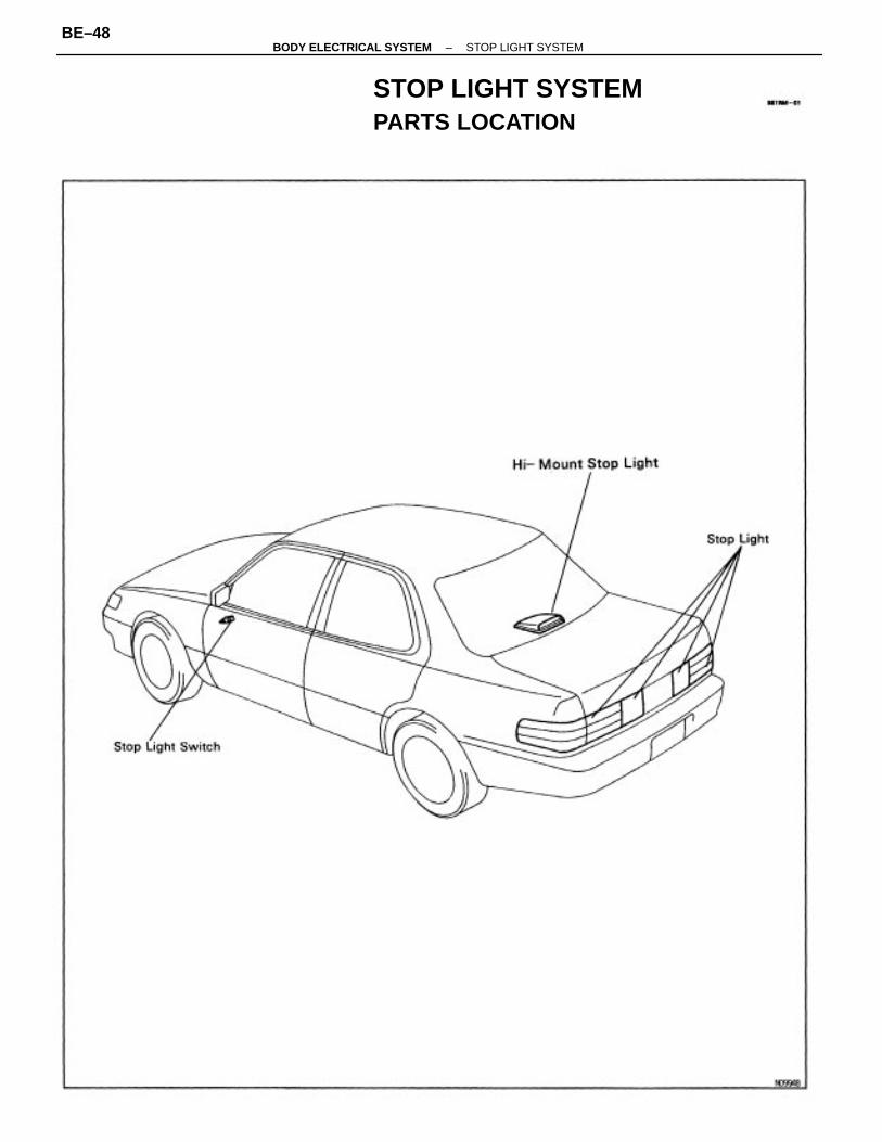
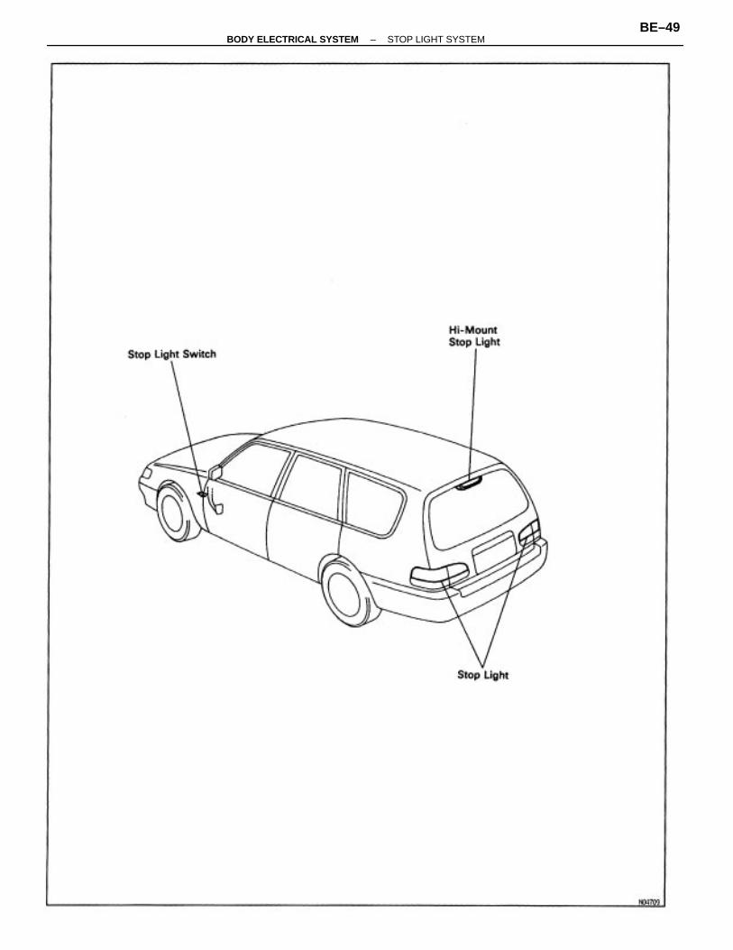
STOP LIGHT SYSTEMPARTS LOCATION
–BODY ELECTRICAL SYSTEM STOP LIGHT SYSTEMBE–48
–BODY ELECTRICAL SYSTEM STOP LIGHT SYSTEMBE–49
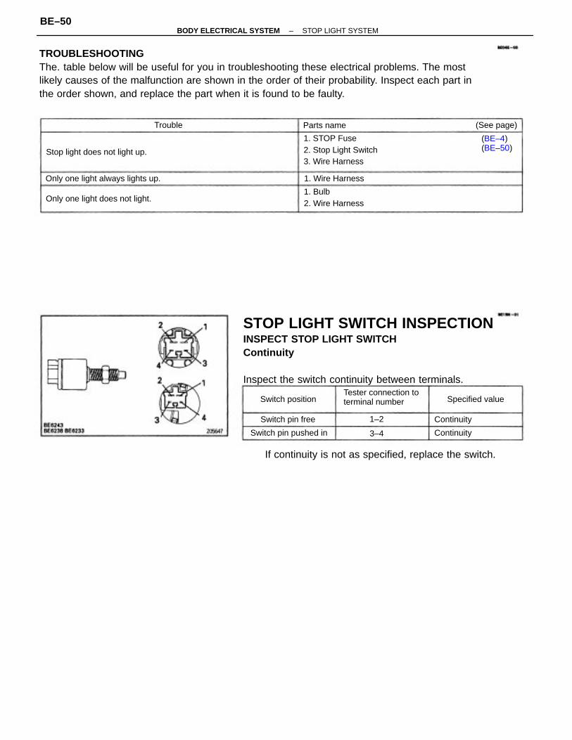
TROUBLESHOOTINGThe. table below will be useful for you in troubleshooting these electrical problems. The mostlikely causes of the malfunction are shown in the order of their probability. Inspect each part inthe order shown, and replace the part when it is found to be faulty.
STOP LIGHT SWITCH INSPECTIONINSPECT STOP LIGHT SWITCHContinuity
Inspect the switch continuity between terminals.
If continuity is not as specified, replace the switch.
1. STOP Fuse2. Stop Light Switch3. Wire Harness
Tester connection toterminal number
Only one light always lights up.
1. Bulb2. Wire HarnessOnly one light does not light.
Stop light does not light up.
Switch pin pushed in
(BE–4)(BE–50)
Switch pin free
Specified valueSwitch position
1. Wire Harness
(See page)Parts name
Continuity
Continuity
Trouble
1–2
3–4
–BODY ELECTRICAL SYSTEM STOP LIGHT SYSTEMBE–50
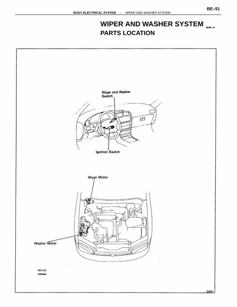
WIPER AND WASHER SYSTEMPARTS LOCATION
–BODY ELECTRICAL SYSTEM WIPER AND WASHER SYSTEMBE–51
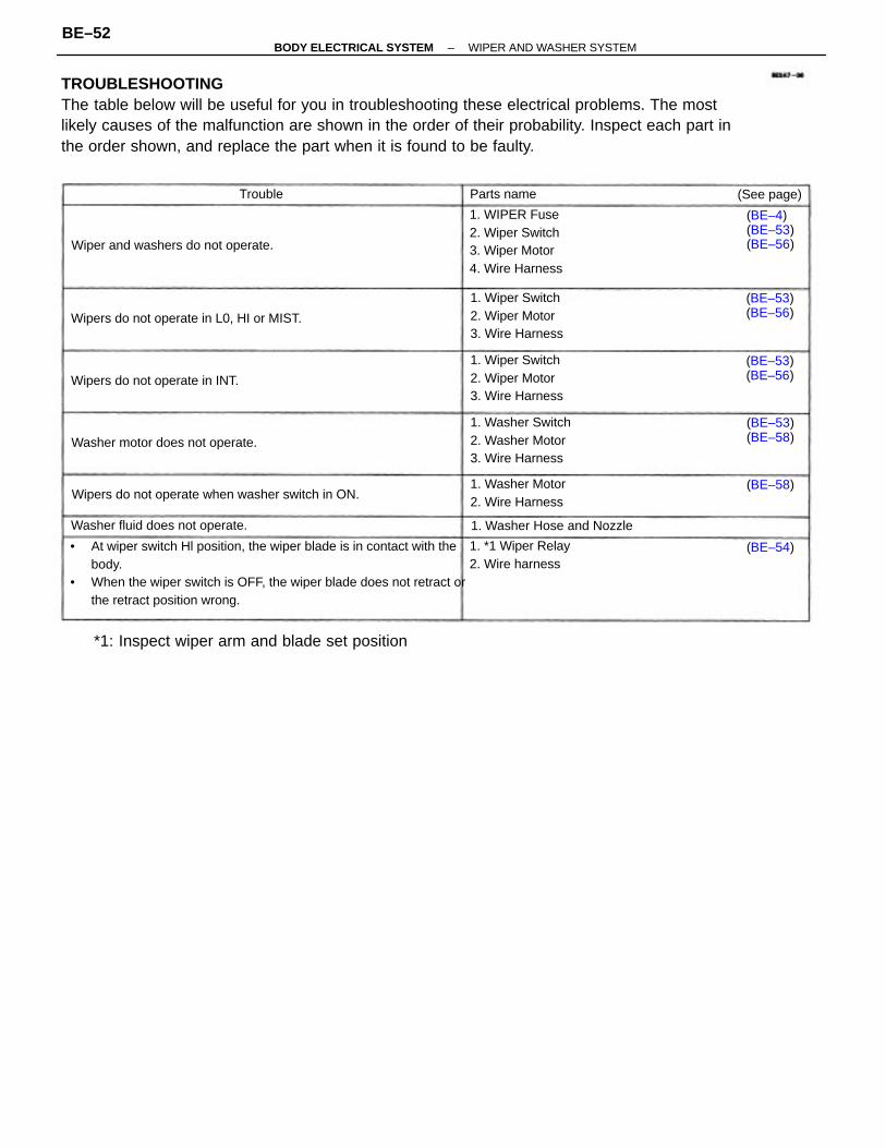
TROUBLESHOOTINGThe table below will be useful for you in troubleshooting these electrical problems. The mostlikely causes of the malfunction are shown in the order of their probability. Inspect each part inthe order shown, and replace the part when it is found to be faulty.
• At wiper switch Hl position, the wiper blade is in contact with thebody.
• When the wiper switch is OFF, the wiper blade does not retract orthe retract position wrong.
*1: Inspect wiper arm and blade set position
1. WIPER Fuse2. Wiper Switch3. Wiper Motor4. Wire Harness
Wipers do not operate when washer switch in ON.
1. Washer Switch2. Washer Motor3. Wire Harness
1. Wiper Switch2. Wiper Motor3. Wire Harness
1. Wiper Switch2. Wiper Motor3. Wire Harness
Wipers do not operate in L0, HI or MIST.
Wiper and washers do not operate.
Washer motor does not operate.
1. *1 Wiper Relay2. Wire harness
1. Washer Motor2. Wire Harness
Washer fluid does not operate.
Wipers do not operate in INT.
(BE–4)(BE–53)(BE–56)
1. Washer Hose and Nozzle
(BE–53)(BE–56)
(BE–53)(BE–56)
(BE–53)(BE–58)
Parts name (See page)
(BE–54)
(BE–58)
Trouble
–BODY ELECTRICAL SYSTEM WIPER AND WASHER SYSTEMBE–52
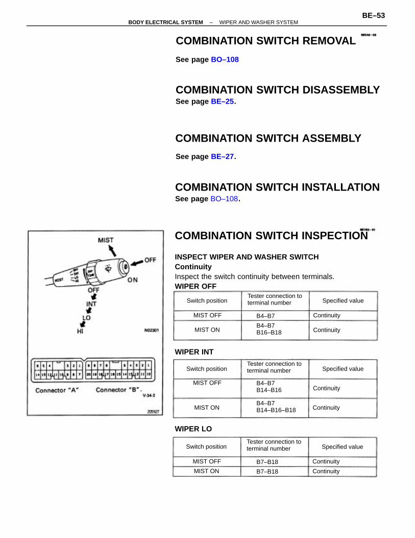
COMBINATION SWITCH INSPECTION
INSPECT WIPER AND WASHER SWITCHContinuityInspect the switch continuity between terminals.WIPER OFF
COMBINATION SWITCH INSTALLATIONSee page BO–108.
COMBINATION SWITCH DISASSEMBLYSee page BE–25.
COMBINATION SWITCH ASSEMBLY
COMBINATION SWITCH REMOVAL
Tester connection toterminal number
Tester connection toterminal number
Tester connection toterminal number
B4–B7B14–B16–B18
See page BO–108
See page BE–27.
B4–B7B14–B16
B4–B7B16–B18
WIPER INT
Specified value
Specified value
Specified value
Switch position
Switch position
Switch position
MIST OFF
WIPER LO
Continuity
B7–B18 Continuity
Continuity
Continuity
Continuity
ContinuityB7–B18
MIST OFF
MIST OFF
MIST ON
MIST ON
MIST ON
B4–B7
–BODY ELECTRICAL SYSTEM WIPER AND WASHER SYSTEMBE–53
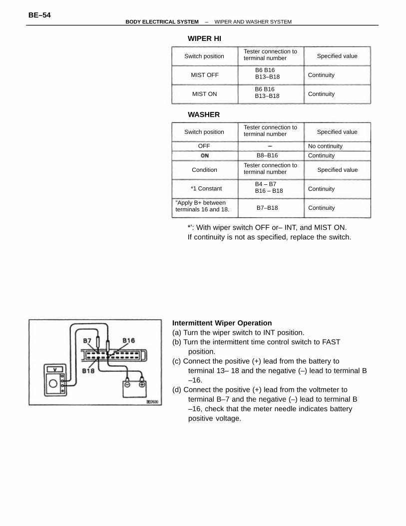
Intermittent Wiper Operation(a) Turn the wiper switch to INT position.(b) Turn the intermittent time control switch to FAST
position.(c) Connect the positive (+) lead from the battery to
terminal 13– 18 and the negative (–) lead to terminal B–16.
(d) Connect the positive (+) lead from the voltmeter toterminal B–7 and the negative (–) lead to terminal B–16, check that the meter needle indicates batterypositive voltage.
*’: With wiper switch OFF or– INT, and MIST ON.If continuity is not as specified, replace the switch.
”Apply B+ betweenterminals 16 and 18.
Tester connection toterminal number
Tester connection toterminal number
Tester connection toterminal number
B4 – B7B16 – B18
B6 B16B13–B18
B6 B16B13–B18
Switch position
Specified value
Specified value
Switch position Specified value
WIPER HI
No continuity
WASHER
Continuity
Continuity
Continuity
ContinuityB7–B18
*1 Constant
Continuity
B8–B16
MIST OFF
Condition
MIST ON
OFF
–BODY ELECTRICAL SYSTEM WIPER AND WASHER SYSTEMBE–54
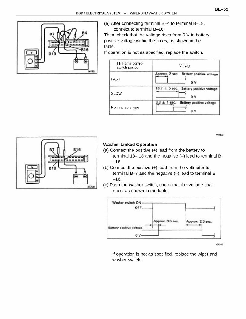
Washer Linked Operation(a) Connect the positive (+) lead from the battery to
terminal 13– 18 and the negative (–) lead to terminal B–16.
(b) Connect the positive (+) lead from the voltmeter toterminal B–7 and the negative (–) lead to terminal B–16.
(c) Push the washer switch, check that the voltage cha–nges, as shown in the table.
(e) After connecting terminal B–4 to terminal B–18,connect to terminal B–16.
Then, check that the voltage rises from 0 V to batterypositive voltage within the times, as shown in thetable.If operation is not as specified, replace the switch.
If operation is not as specified, replace the wiper andwasher switch.
I NT time controlswitch position
Non variable type
Voltage
SLOW
FAST
–BODY ELECTRICAL SYSTEM WIPER AND WASHER SYSTEMBE–55
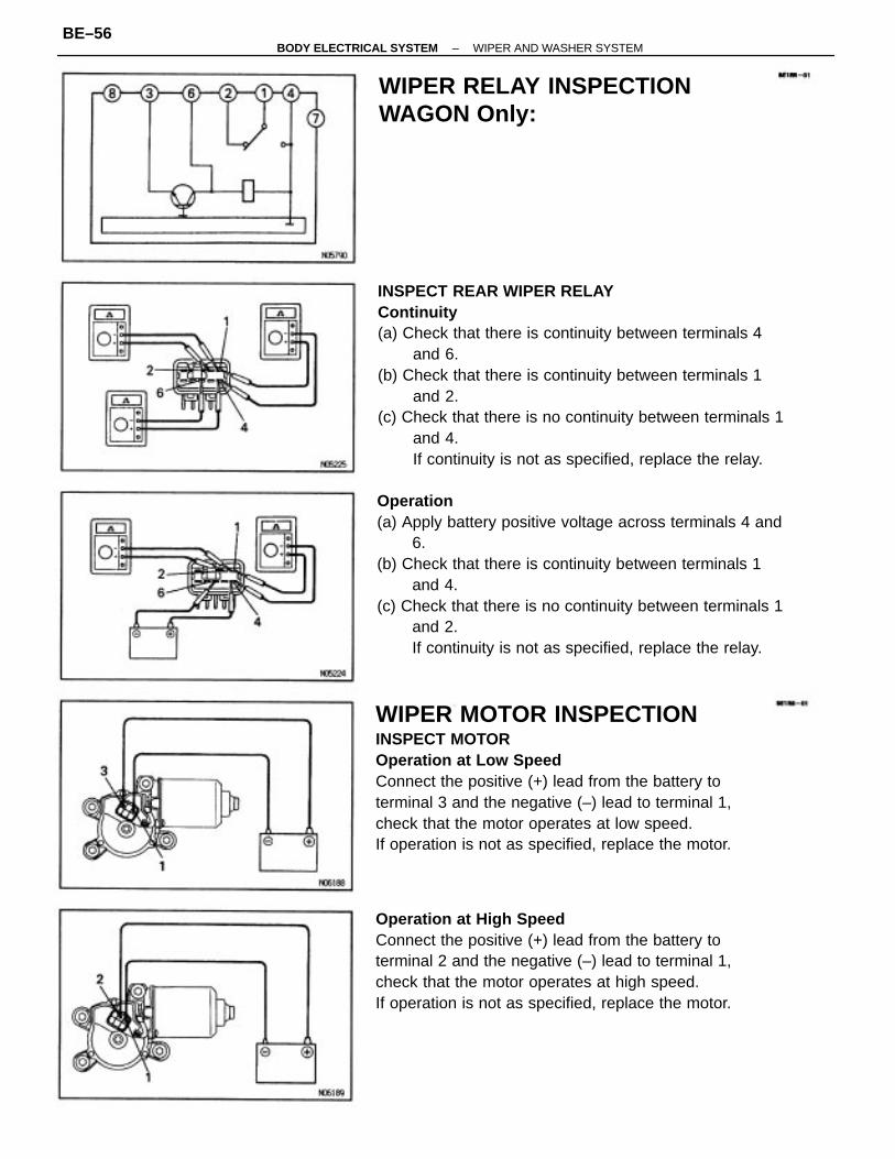
INSPECT REAR WIPER RELAYContinuity(a) Check that there is continuity between terminals 4
and 6.(b) Check that there is continuity between terminals 1
and 2.(c) Check that there is no continuity between terminals 1
and 4.If continuity is not as specified, replace the relay.
Operation(a) Apply battery positive voltage across terminals 4 and
6.(b) Check that there is continuity between terminals 1
and 4.(c) Check that there is no continuity between terminals 1
and 2.If continuity is not as specified, replace the relay.
WIPER MOTOR INSPECTIONINSPECT MOTOROperation at Low SpeedConnect the positive (+) lead from the battery toterminal 3 and the negative (–) lead to terminal 1,check that the motor operates at low speed.If operation is not as specified, replace the motor.
Operation at High SpeedConnect the positive (+) lead from the battery toterminal 2 and the negative (–) lead to terminal 1,check that the motor operates at high speed.If operation is not as specified, replace the motor.
WIPER RELAY INSPECTIONWAGON Only:
–BODY ELECTRICAL SYSTEM WIPER AND WASHER SYSTEMBE–56
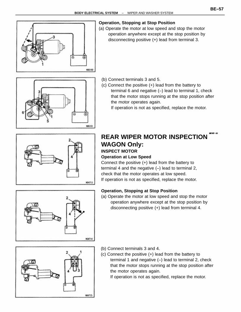
REAR WIPER MOTOR INSPECTIONWAGON Only:INSPECT MOTOROperation at Low SpeedConnect the positive (+) lead from the battery toterminal 4 and the negative (–) lead to terminal 2,check that the motor operates at low speed.If operation is not as specified, replace the motor.
Operation, Stopping at Stop Position(a) Operate the motor at low speed and stop the motor
operation anywhere except at the stop position bydisconnecting positive (+) lead from terminal 4.
(b) Connect terminals 3 and 4.(c) Connect the positive (+) lead from the battery to
terminal 1 and negative (–) lead to terminal 2, checkthat the motor stops running at the stop position afterthe motor operates again.If operation is not as specified, replace the motor.
(b) Connect terminals 3 and 5.(c) Connect the positive (+) lead from the battery to
terminal 6 and negative (–) lead to terminal 1, checkthat the motor stops running at the stop position afterthe motor operates again.If operation is not as specified, replace the motor.
Operation, Stopping at Stop Position(a) Operate the motor at low speed and stop the motor
operation anywhere except at the stop position bydisconnecting positive (+) lead from terminal 3.
–BODY ELECTRICAL SYSTEM WIPER AND WASHER SYSTEMBE–57
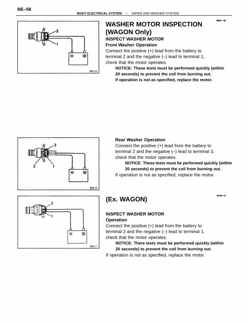
WASHER MOTOR INSPECTION(WAGON Only)INSPECT WASHER MOTORFront Washer OperationConnect the positive (+) lead from the battery toterminal 2 and the negative (–) lead to terminal 1,check that the motor operates.
NOTICE: These tests must be performed quickly (within20 seconds) to prevent the coil from burning out.If operation is not as specified, replace the motor.
(Ex. WAGON)
INSPECT WASHER MOTOROperationConnect the positive (+) lead from the battery toterminal 2 and the negative (–) lead to terminal 1,check that the motor operates.
NOTICE: There tests must be performed quickly (within20 seconds) to prevent the coil from burning out.
If operation is not as specified, replace the motor.
Rear Washer OperationConnect the positive (+) lead from the battery toterminal 2 and the negative (–) lead to terminal 3,check that the motor operates.
NOTICE: These tests must be performed quickly (within20 seconds) to prevent the coil from burning out.
If operation is not as specified, replace the motor.
–BODY ELECTRICAL SYSTEM WIPER AND WASHER SYSTEMBE–58
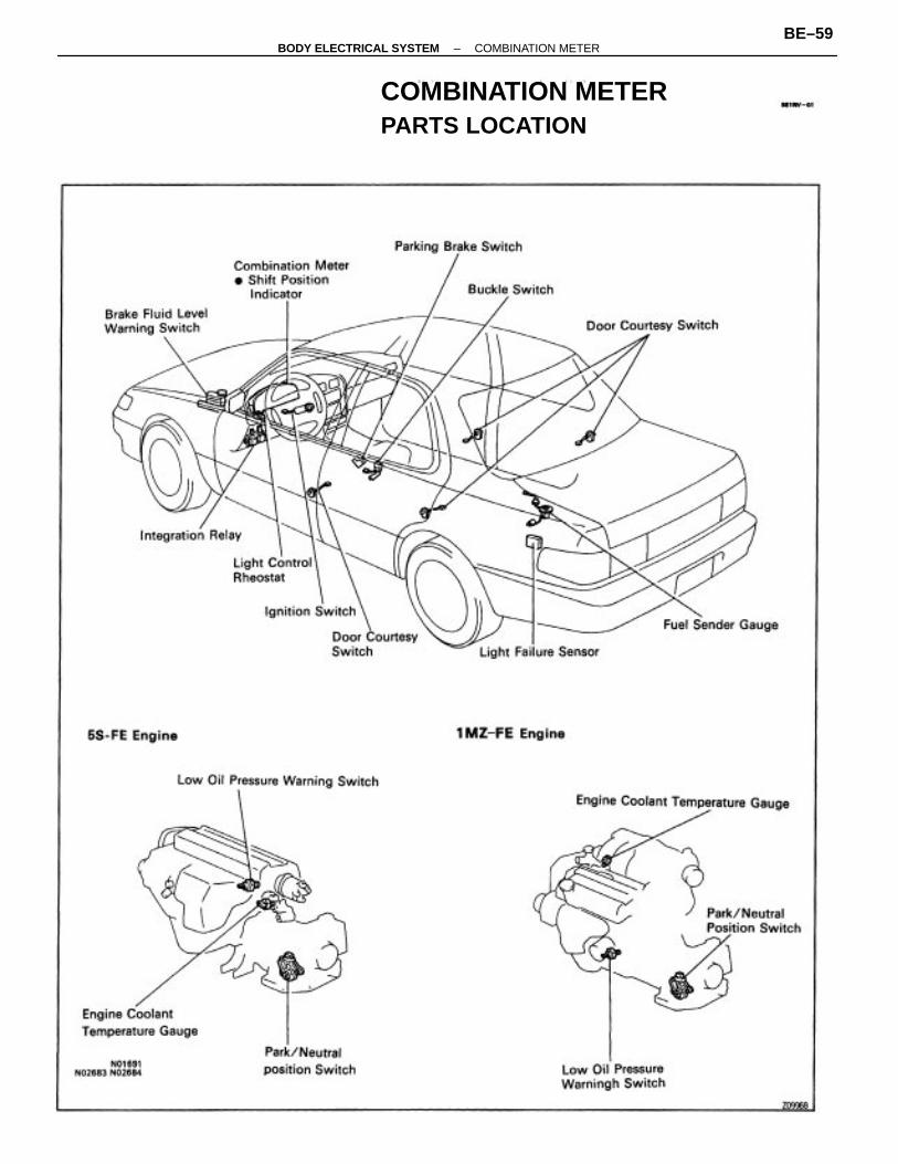
COMBINATION METERPARTS LOCATION
–BODY ELECTRICAL SYSTEM COMBINATION METERBE–59
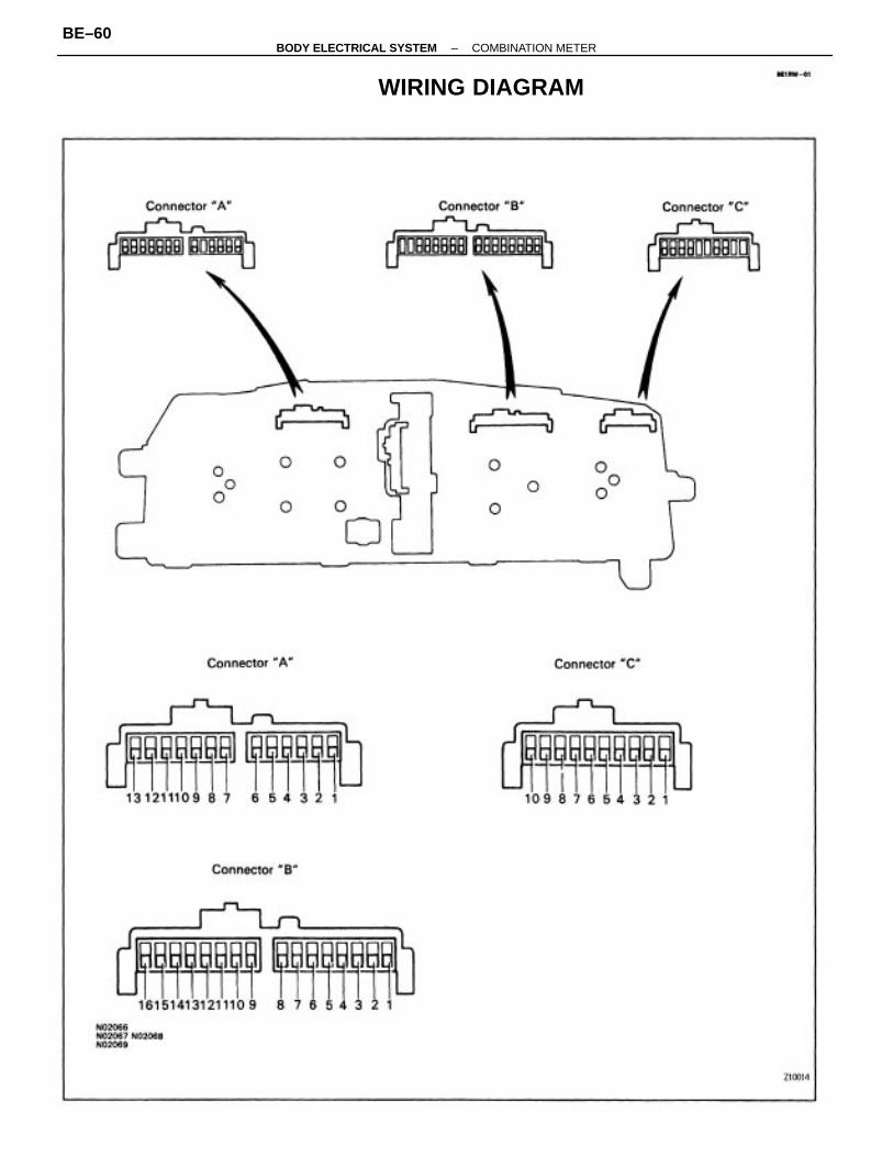
WIRING DIAGRAM
–BODY ELECTRICAL SYSTEM COMBINATION METERBE–60
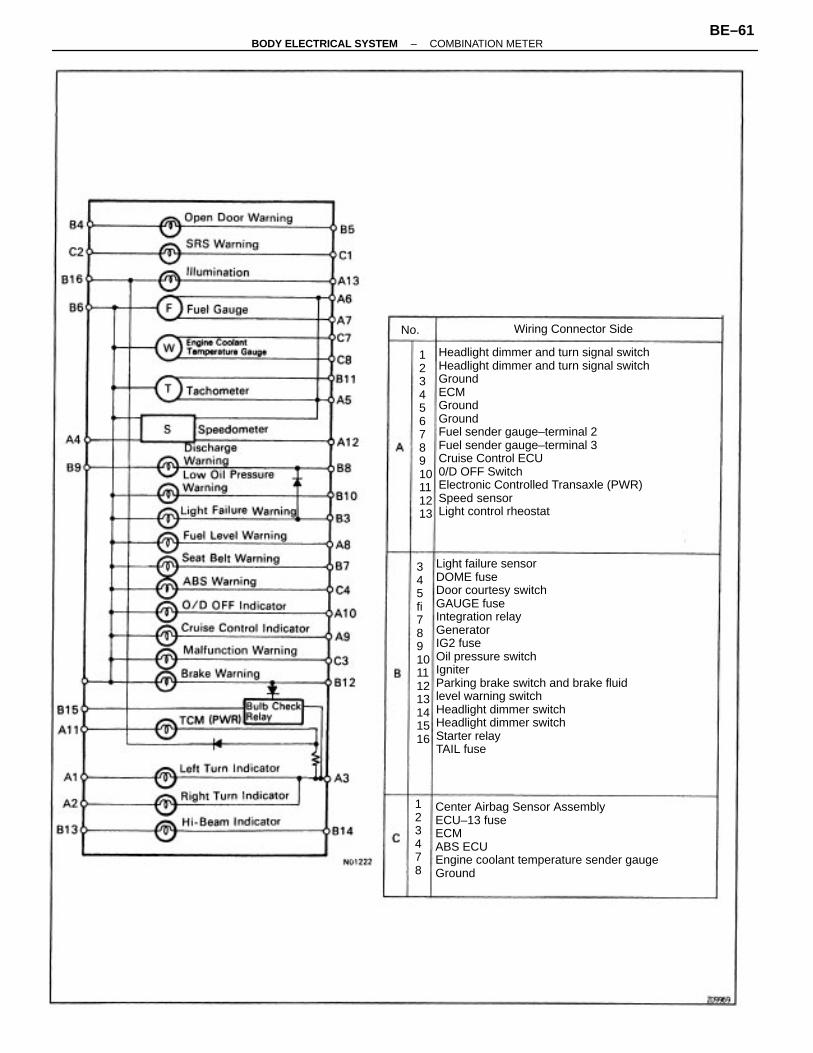
Light failure sensorDOME fuseDoor courtesy switchGAUGE fuseIntegration relayGeneratorIG2 fuseOil pressure switchIgniterParking brake switch and brake fluidlevel warning switchHeadlight dimmer switchHeadlight dimmer switchStarter relayTAIL fuse
Headlight dimmer and turn signal switchHeadlight dimmer and turn signal switchGroundECMGroundGroundFuel sender gauge–terminal 2Fuel sender gauge–terminal 3Cruise Control ECU0/D OFF SwitchElectronic Controlled Transaxle (PWR)Speed sensorLight control rheostat
Center Airbag Sensor AssemblyECU–13 fuseECMABS ECUEngine coolant temperature sender gaugeGround
345fi78910111213141516
12345678910111213
Wiring Connector SideNo.
123478
–BODY ELECTRICAL SYSTEM COMBINATION METERBE–61
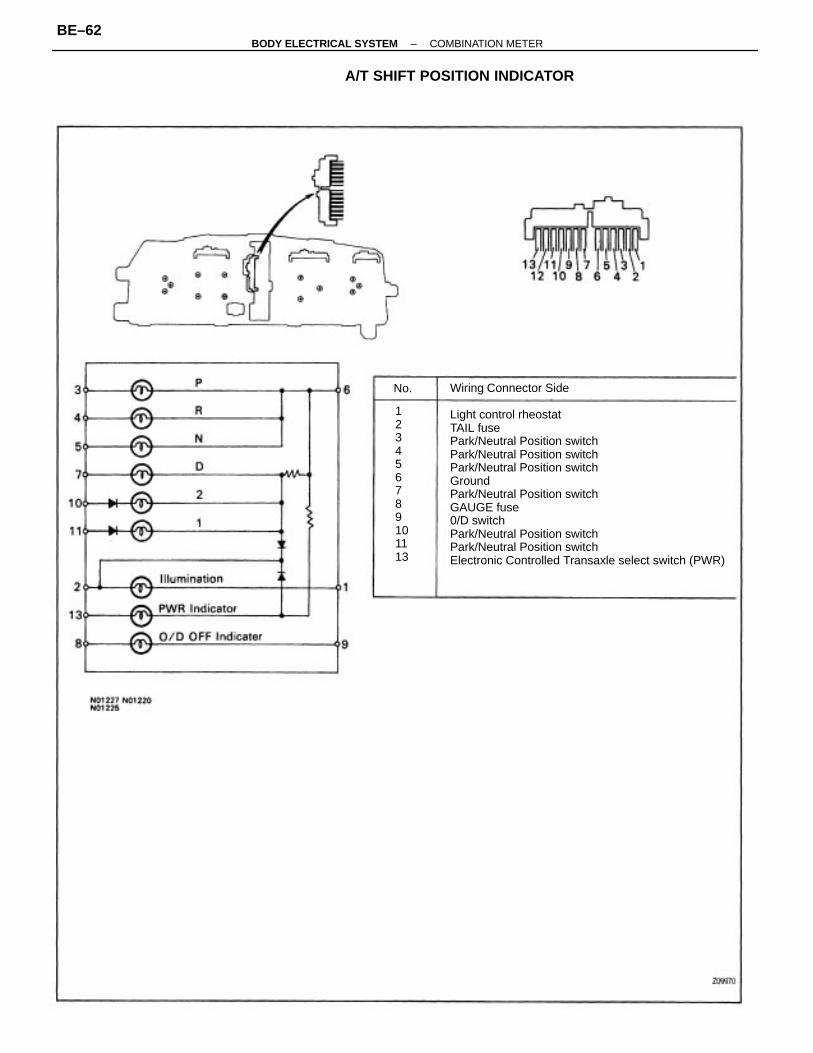
Wiring Connector Side
Light control rheostatTAIL fusePark/Neutral Position switchPark/Neutral Position switchPark/Neutral Position switchGroundPark/Neutral Position switchGAUGE fuse0/D switchPark/Neutral Position switchPark/Neutral Position switchElectronic Controlled Transaxle select switch (PWR)
A/T SHIFT POSITION INDICATOR
123456789101113
No.
–BODY ELECTRICAL SYSTEM COMBINATION METERBE–62
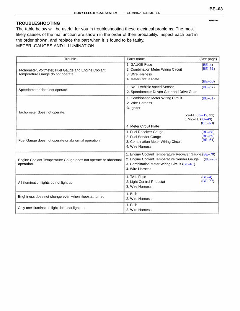
TROUBLESHOOTINGThe table below will be useful for you in troubleshooting these electrical problems. The mostlikely causes of the malfunction are shown in the order of their probability. Inspect each part inthe order shown, and replace the part when it is found to be faulty.METER, GAUGES AND ILLUMINATION
1. Engine Coolant Temperature Receiver Gauge (BE–70)2. Engine Coolant Temperature Sender Gauge (BE–70)3. Combination Meter Wiring Circuit (BE–61)4. Wire Harness
Engine Coolant Temperature Gauge does not operate or abnormaloperation.
Tachometer, Voltmeter, Fuel Gauge and Engine Coolant Temperature Gauge do not operate.
1. GAUGE Fuse2. Combination Meter Wiring Circuit3. Wire Harness4. Meter Circuit Plate
1. Fuel Receiver Gauge2. Fuel Sender Gauge3. Combination Meter Wiring Circuit4. Wire Harness
1. Combination Meter Wiring Circuit2. Wire Harness3. Igniter
1. No. 1 vehicle speed Sensor2. Speedometer Driven Gear and Drive Gear
1. TAIL Fuse2. Light Control Rheostat3. Wire Harness
Brightness does not change even when rheostat turned.
5S–FE (IG–12, 31)1 MZ–FE (IG–49)
(BE–60)
Fuel Gauge does not operate or abnormal operation.
Only one illumination light does not light up.
All illumination lights do not light up.
Speedometer does not operate.
Tachometer does not operate.
1. Bulb2. Wire Harness
1. Bulb2. Wire Harness
(BE–68)(BE–69)(BE–61)
4. Meter Circuit Plate
(BE–4)(BE–61)
(BE–4)(BE–77)
(See page)Parts name
(BE–61)
(BE–60)
(BE–67)
Trouble
–BODY ELECTRICAL SYSTEM COMBINATION METERBE–63
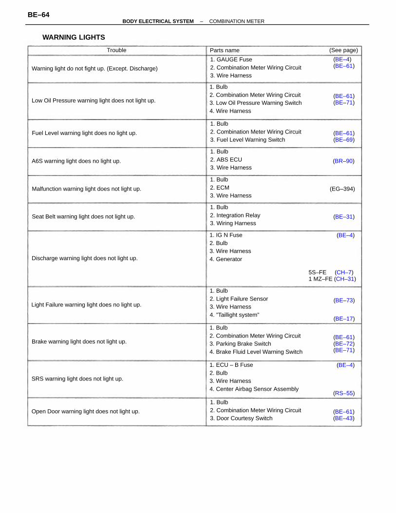
1. Bulb2. Combination Meter Wiring Circuit3. Parking Brake Switch4. Brake Fluid Level Warning Switch
1. Bulb2. Combination Meter Wiring Circuit3. Low Oil Pressure Warning Switch4. Wire Harness
1. ECU – B Fuse2. Bulb3. Wire Harness4. Center Airbag Sensor Assembly
1. Bulb2. Combination Meter Wiring Circuit3. Door Courtesy Switch
1. Bulb2. Combination Meter Wiring Circuit3. Fuel Level Warning Switch
1. GAUGE Fuse2. Combination Meter Wiring Circuit3. Wire Harness
1. Bulb2. Light Failure Sensor3. Wire Harness4. ”Taillight system”
1. IG N Fuse2. Bulb3. Wire Harness4. Generator
1. Bulb2. Integration Relay3. Wiring Harness
Warning light do not fight up. (Except. Discharge)
Low Oil Pressure warning light does not light up.
Malfunction warning light does not light up.
Light Failure warning light does no light up.
1. Bulb2. ABS ECU3. Wire Harness
Open Door warning light does not light up.
1. Bulb2. ECM3. Wire Harness
Fuel Level warning light does no light up.
Discharge warning light does not light up.
Seat Belt warning light does not light up.
Brake warning light does not light up.
5S–FE (CH–7)1 MZ–FE (CH–31)
SRS warning light does not light up.
A6S warning light does no light up.
WARNING LIGHTS
(BE–61)(BE–72)(BE–71)
(BE–61)(BE–43)
(BE–61)(BE–71)
(BE–61)(BE–69)
(BE–4)(BE–61)
(See page)Parts name
(EG–394)
(BR–90)
(RS–55)
(BE–17)
(BE–31)
(BE–73)
(BE–4)
(BE–4)
Trouble
–BODY ELECTRICAL SYSTEM COMBINATION METERBE–64
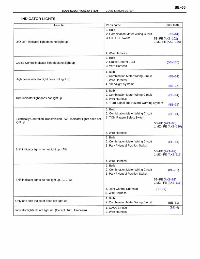
1. Bulb2. Combination Meter Wiring Circuit3. Wire Harness4. ”Turn Signal and Hazard Warning System”
Electrically Controlled Transmission PWR indicator lights does notlight up.
1. Bulb2. Combination Meter Wiring Circuit3. Wire Harness4. ”Headlight System”
1. Bulb2. Combination Meter Wiring Circuit3. Park / Neutral Position Switch
1. Bulb2. Combination Meter Wiring Circuit3. Park / Neutral Position Switch
1. Bulb2. Combination Meter Wiring Circuit3. O/D OFF Switch
1. Bulb2. Combination Meter Wiring Circuit3. TCM Pattern Select Switch
1. Bulb2. Combination Meter Wiring Circuit
Indicator lights do not light up. (Except. Turn, Hi–beam)
1. Bulb2. Cruise Control ECU3. Wire Harness
5S–FE (AX1–92)1 MZ– FE (AX2–116)
Cruise Control indicator light does not light up.
Shift indicator lights do not light up. (L. 2. D)
4. Light Control Rheostat5. Wire Harness
High beam indicator light does not light up.
O/D OFF indicator light does not light up.
Only one shift indicator does not light up.
Shift indicator lights do not light up. (All)5S–FE (AX1–92)1 MZ– FE (AX2–116)
5S–FE (AX1–98)1 MZ– FE (AX2–126)
Turn indicator light does not light up.
5S–FE (AX1–102)1 MZ–FE (AX2–130)
INDICATOR LIGHTS
1. GAUGE Fuse2. Wire Harness
4. Wire Harness
4. Wire Harness
4. Wire Harness
(see page)Parts name
(BE–176)
(BE–17)
(BE–61)
(BE–61)
(BE–61)
(BE–61)
(BE–61)
(BE–35)
(BE–61)
(BE–61)
(BE–4)
Trouble
(BE–77)
–BODY ELECTRICAL SYSTEM COMBINATION METERBE–65
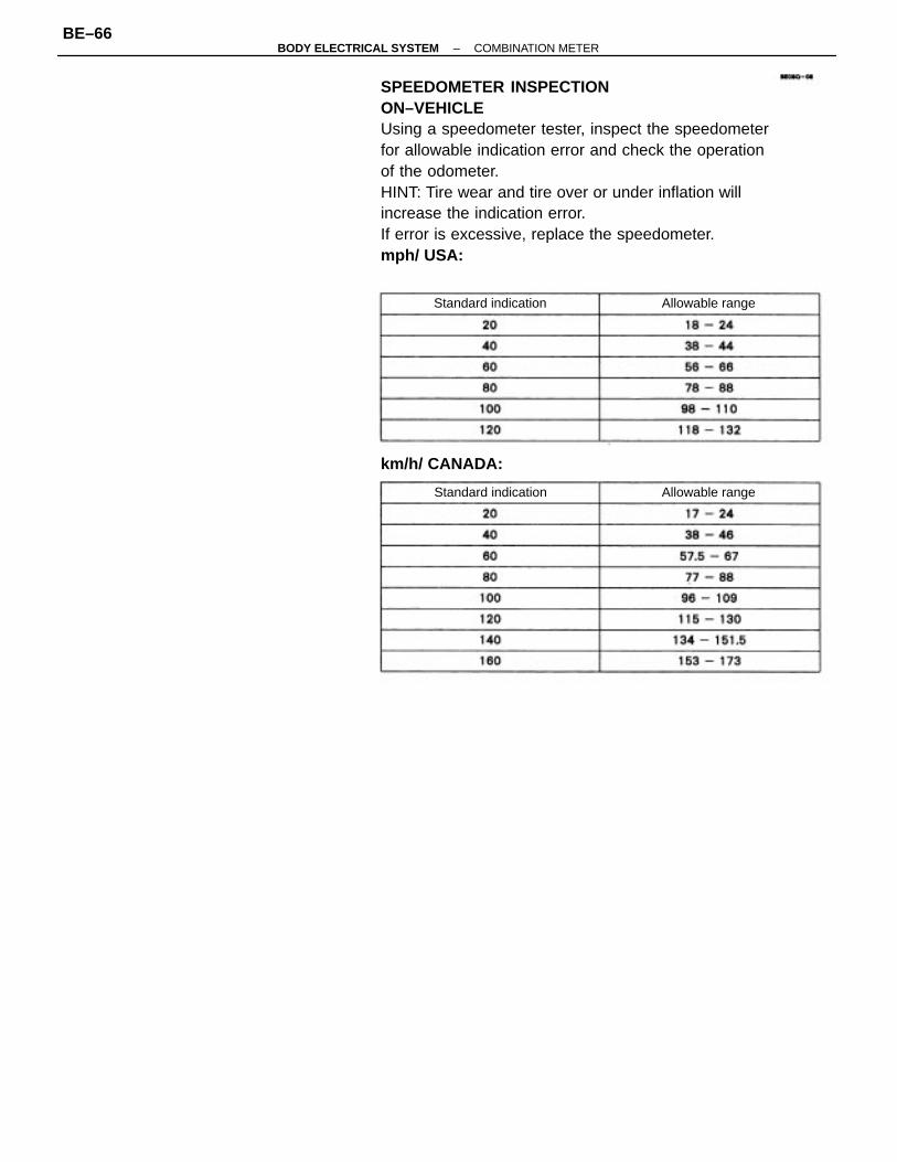
SPEEDOMETER INSPECTIONON–VEHICLEUsing a speedometer tester, inspect the speedometerfor allowable indication error and check the operationof the odometer.HINT: Tire wear and tire over or under inflation willincrease the indication error.If error is excessive, replace the speedometer.mph/ USA:
km/h/ CANADA:
Standard indication
Standard indication
Allowable range
Allowable range
–BODY ELECTRICAL SYSTEM COMBINATION METERBE–66
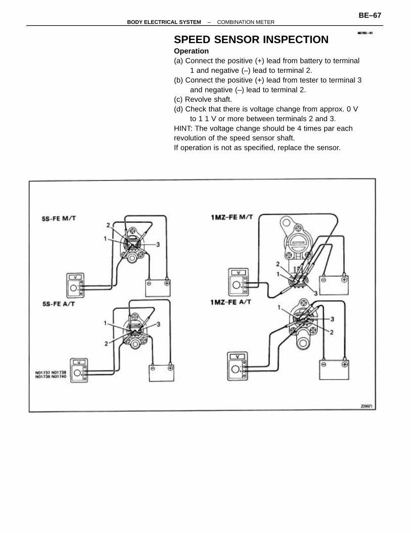
SPEED SENSOR INSPECTIONOperation(a) Connect the positive (+) lead from battery to terminal
1 and negative (–) lead to terminal 2.(b) Connect the positive (+) lead from tester to terminal 3
and negative (–) lead to terminal 2.(c) Revolve shaft.(d) Check that there is voltage change from approx. 0 V
to 1 1 V or more between terminals 2 and 3.HINT: The voltage change should be 4 times par eachrevolution of the speed sensor shaft.If operation is not as specified, replace the sensor.
–BODY ELECTRICAL SYSTEM COMBINATION METERBE–67
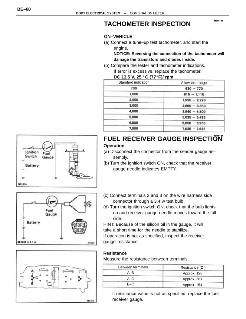
(c) Connect terminals 2 and 3 on the wire harness sideconnector through a 3.4 w test bulb.
(d) Turn the ignition switch ON, check that the bulb lightsup and receiver gauge needle moves toward the fullside.
HINT: Because of the silicon oil in the gauge, it willtake a short time for the needle to stabilize.If operation is not as specified, inspect the receivergauge resistance.
ResistanceMeasure the resistance between terminals.
TACHOMETER INSPECTION
ON–VEHICLE(a) Connect a tune–up test tachometer, and start the
engine.NOTICE: Reversing the connection of the tachometer willdamage the transistors and diodes inside.
(b) Compare the tester and tachometer indications.If error is excessive, replace the tachometer.DC 13.5 V, 25 C (77F)/ rpm
FUEL RECEIVER GAUGE INSPECTIONOperation(a) Disconnect the connector from the sender gauge as–
sembly.(b) Turn the ignition switch ON, check that the receiver
gauge needle indicates EMPTY.
If resistance value is not as specified, replace the fuelreceiver gauge.
Standard indication
Between terminals
Allowable range
Resistance (Ω )
Approx. 154
Approx. 281
Approx. 126A–B
B–C
A–C
–BODY ELECTRICAL SYSTEM COMBINATION METERBE–68
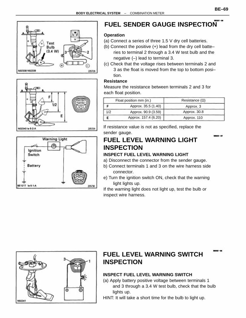
If resistance value is not as specified, replace thesender gauge.
FUEL LEVEL WARNING LIGHTINSPECTIONINSPECT FUEL LEVEL WARNING LIGHTa) Disconnect the connector from the sender gauge.b) Connect terminals 1 and 3 on the wire harness side
connector.e) Turn the ignition switch ON, check that the warning
light lights up.If the warning light does not light up, test the bulb orinspect wire harness.
Operation(a) Connect a series of three 1.5 V dry cell batteries.(b) Connect the positive (+) lead from the dry cell batte–
ries to terminal 2 through a 3.4 W test bulb and thenegative (–) lead to terminal 3.
(c) Check that the voltage rises between terminals 2 and3 as the float is moved from the top to bottom posi–tion.
ResistanceMeasure the resistance between terminals 2 and 3 foreach float position.
FUEL LEVEL WARNING SWITCHINSPECTION
INSPECT FUEL LEVEL WARNING SWITCH(a) Apply battery positive voltage between terminals 1
and 3 through a 3.4 W test bulb, check that the bulblights up.
HINT: It will take a short time for the bulb to light up.
FUEL SENDER GAUGE INSPECTION
Float position mm (in.)
Approx. 157.4 (6.20)
Approx. 35.5 (1.40)
Approx. 90.9 (3.59)
Resistance (Ω)
Approx. 30.8
Approx. 110
Approx. 3
1/2
–BODY ELECTRICAL SYSTEM COMBINATION METERBE–69
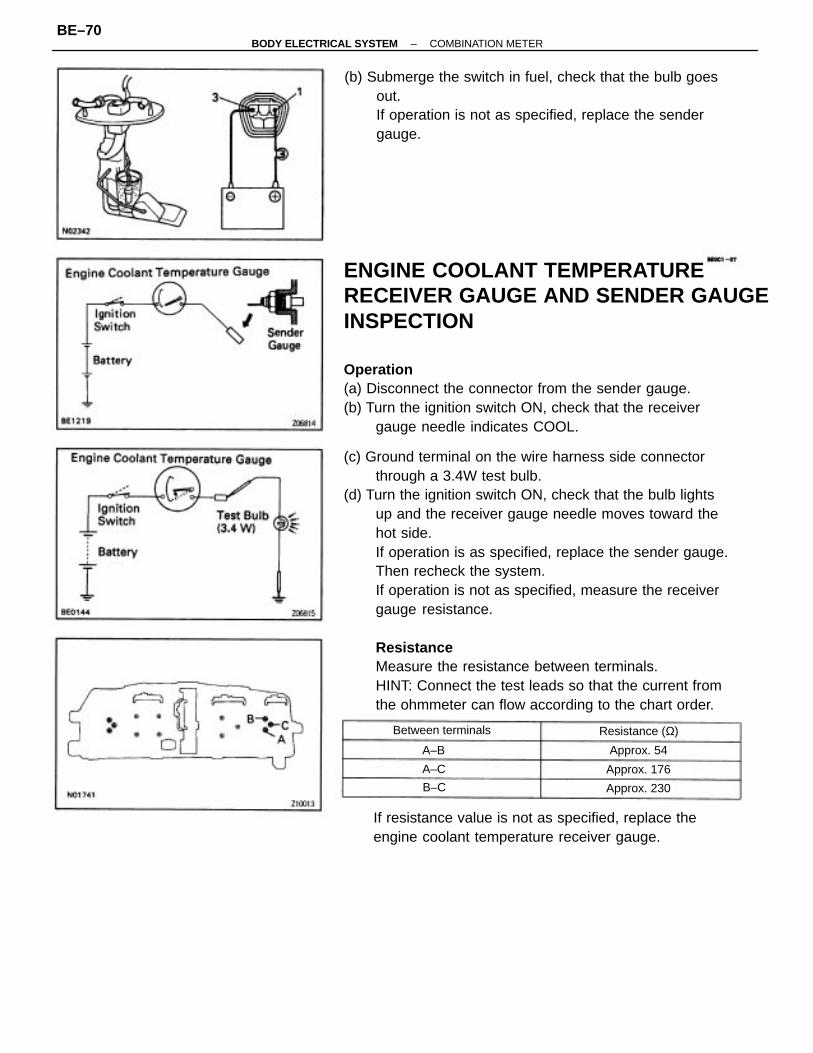
(c) Ground terminal on the wire harness side connectorthrough a 3.4W test bulb.
(d) Turn the ignition switch ON, check that the bulb lightsup and the receiver gauge needle moves toward thehot side.If operation is as specified, replace the sender gauge.Then recheck the system.If operation is not as specified, measure the receivergauge resistance.
ResistanceMeasure the resistance between terminals.HINT: Connect the test leads so that the current fromthe ohmmeter can flow according to the chart order.
ENGINE COOLANT TEMPERATURERECEIVER GAUGE AND SENDER GAUGEINSPECTION
Operation(a) Disconnect the connector from the sender gauge.(b) Turn the ignition switch ON, check that the receiver
gauge needle indicates COOL.
(b) Submerge the switch in fuel, check that the bulb goesout.If operation is not as specified, replace the sendergauge.
If resistance value is not as specified, replace theengine coolant temperature receiver gauge.
Between terminals Resistance (Ω)
Approx. 230
Approx. 176
Approx. 54
B–C
A–C
A–B
–BODY ELECTRICAL SYSTEM COMBINATION METERBE–70
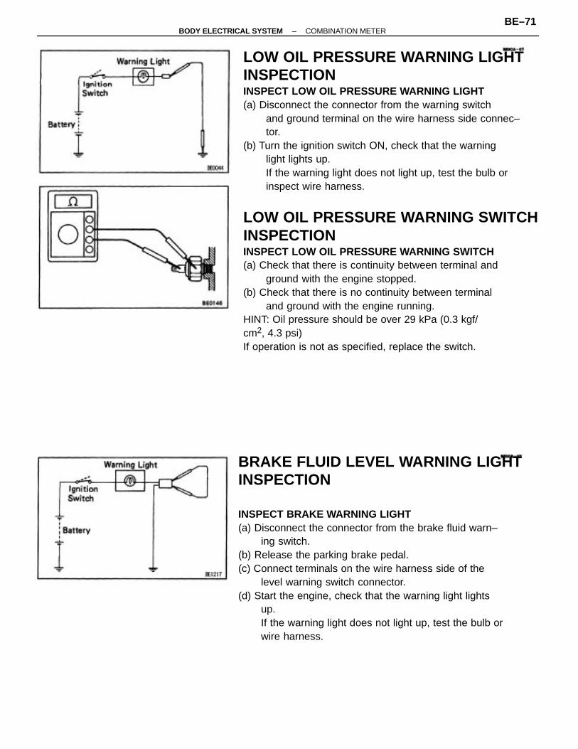
LOW OIL PRESSURE WARNING LIGHTINSPECTIONINSPECT LOW OIL PRESSURE WARNING LIGHT(a) Disconnect the connector from the warning switch
and ground terminal on the wire harness side connec–tor.
(b) Turn the ignition switch ON, check that the warninglight lights up.If the warning light does not light up, test the bulb orinspect wire harness.
LOW OIL PRESSURE WARNING SWITCHINSPECTIONINSPECT LOW OIL PRESSURE WARNING SWITCH(a) Check that there is continuity between terminal and
ground with the engine stopped.(b) Check that there is no continuity between terminal
and ground with the engine running.HINT: Oil pressure should be over 29 kPa (0.3 kgf/cm2, 4.3 psi)If operation is not as specified, replace the switch.
BRAKE FLUID LEVEL WARNING LIGHTINSPECTION
INSPECT BRAKE WARNING LIGHT(a) Disconnect the connector from the brake fluid warn–
ing switch.(b) Release the parking brake pedal.(c) Connect terminals on the wire harness side of the
level warning switch connector.(d) Start the engine, check that the warning light lights
up.If the warning light does not light up, test the bulb orwire harness.
–BODY ELECTRICAL SYSTEM COMBINATION METERBE–71
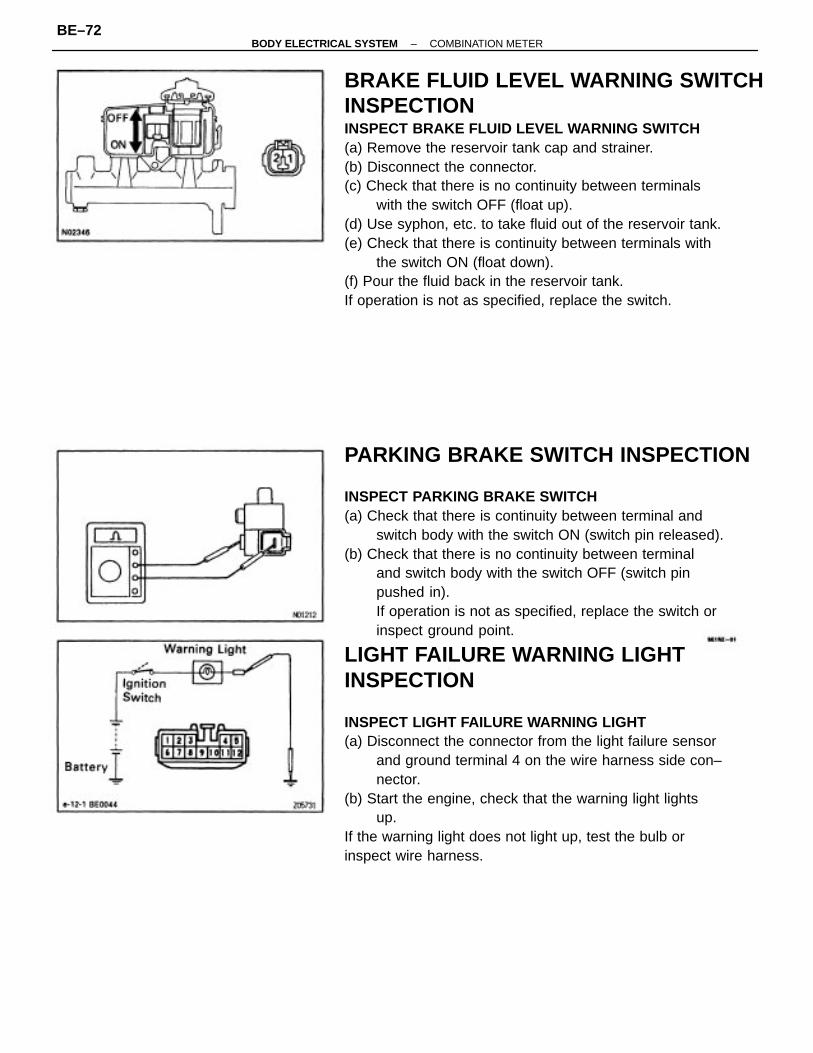
PARKING BRAKE SWITCH INSPECTION
INSPECT PARKING BRAKE SWITCH(a) Check that there is continuity between terminal and
switch body with the switch ON (switch pin released).(b) Check that there is no continuity between terminal
and switch body with the switch OFF (switch pinpushed in).If operation is not as specified, replace the switch orinspect ground point.
LIGHT FAILURE WARNING LIGHTINSPECTION
INSPECT LIGHT FAILURE WARNING LIGHT(a) Disconnect the connector from the light failure sensor
and ground terminal 4 on the wire harness side con–nector.
(b) Start the engine, check that the warning light lightsup.
If the warning light does not light up, test the bulb orinspect wire harness.
BRAKE FLUID LEVEL WARNING SWITCHINSPECTIONINSPECT BRAKE FLUID LEVEL WARNING SWITCH(a) Remove the reservoir tank cap and strainer.(b) Disconnect the connector.(c) Check that there is no continuity between terminals
with the switch OFF (float up).(d) Use syphon, etc. to take fluid out of the reservoir tank.(e) Check that there is continuity between terminals with
the switch ON (float down).(f) Pour the fluid back in the reservoir tank.If operation is not as specified, replace the switch.
–BODY ELECTRICAL SYSTEM COMBINATION METERBE–72
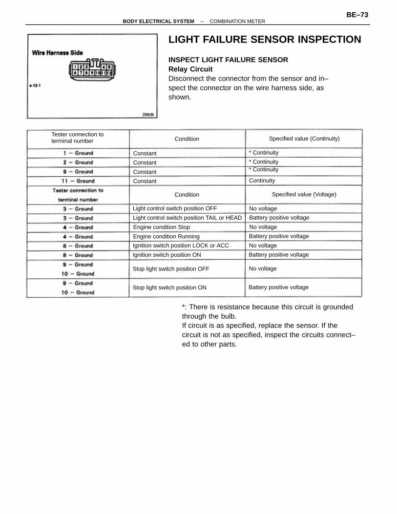
LIGHT FAILURE SENSOR INSPECTION
INSPECT LIGHT FAILURE SENSORRelay CircuitDisconnect the connector from the sensor and in–spect the connector on the wire harness side, asshown.
*: There is resistance because this circuit is groundedthrough the bulb.If circuit is as specified, replace the sensor. If thecircuit is not as specified, inspect the circuits connect–ed to other parts.
Light control switch position TAIL or HEAD
Ignition switch position LOCK or ACC
Tester connection toterminal number
Light control switch position OFF
Stop light switch position OFF
Stop light switch position ON
Specified value (Continuity)
Ignition switch position ON
Engine condition Running
Specified value (Voltage)
Battery positive voltage
Battery positive voltage
Battery positive voltage
Battery positive voltage
Engine condition Stop
Constant
* Continuity* Continuity
* Continuity
No voltage
No voltage
No voltage
No voltage
Continuity
Condition
Condition
Constant
Constant
Constant
–BODY ELECTRICAL SYSTEM COMBINATION METERBE–73
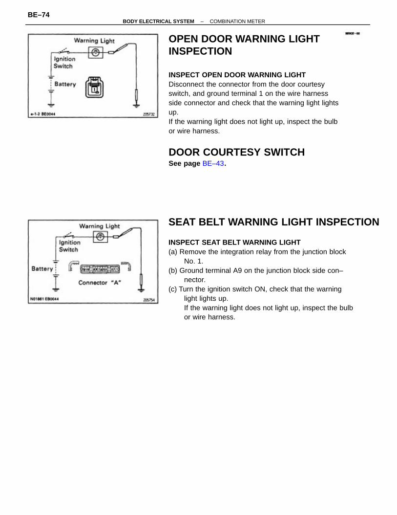
OPEN DOOR WARNING LIGHTINSPECTION
INSPECT OPEN DOOR WARNING LIGHTDisconnect the connector from the door courtesyswitch, and ground terminal 1 on the wire harnessside connector and check that the warning light lightsup.If the warning light does not light up, inspect the bulbor wire harness.
DOOR COURTESY SWITCHSee page BE–43.
SEAT BELT WARNING LIGHT INSPECTION
INSPECT SEAT BELT WARNING LIGHT(a) Remove the integration relay from the junction block
No. 1.(b) Ground terminal A9 on the junction block side con–
nector.(c) Turn the ignition switch ON, check that the warning
light lights up.If the warning light does not light up, inspect the bulbor wire harness.
–BODY ELECTRICAL SYSTEM COMBINATION METERBE–74
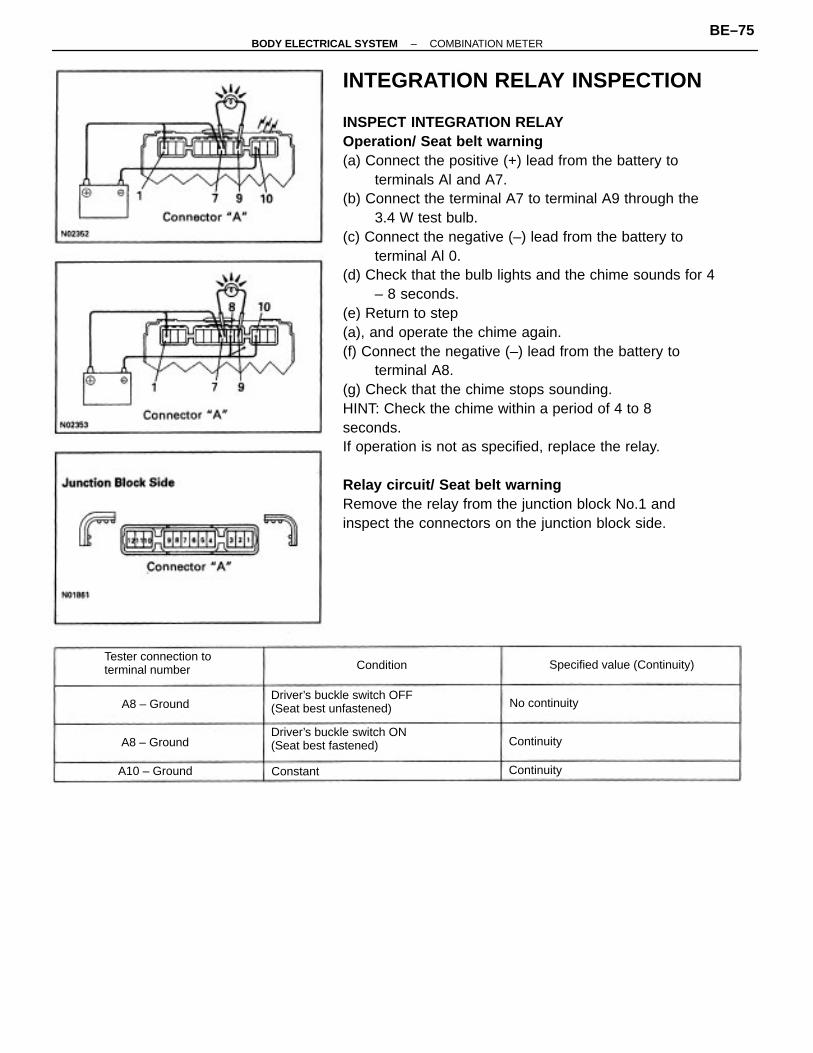
INTEGRATION RELAY INSPECTION
INSPECT INTEGRATION RELAYOperation/ Seat belt warning(a) Connect the positive (+) lead from the battery to
terminals Al and A7.(b) Connect the terminal A7 to terminal A9 through the
3.4 W test bulb.(c) Connect the negative (–) lead from the battery to
terminal Al 0.(d) Check that the bulb lights and the chime sounds for 4
– 8 seconds.(e) Return to step(a), and operate the chime again.(f) Connect the negative (–) lead from the battery to
terminal A8.(g) Check that the chime stops sounding.HINT: Check the chime within a period of 4 to 8seconds.If operation is not as specified, replace the relay.
Relay circuit/ Seat belt warningRemove the relay from the junction block No.1 andinspect the connectors on the junction block side.
Driver’s buckle switch OFF(Seat best unfastened)
Driver’s buckle switch ON(Seat best fastened)
Tester connection toterminal number Specified value (Continuity)
A10 – Ground
No continuity
A8 – Ground
A8 – Ground
Continuity
Continuity
Condition
Constant
–BODY ELECTRICAL SYSTEM COMBINATION METERBE–75
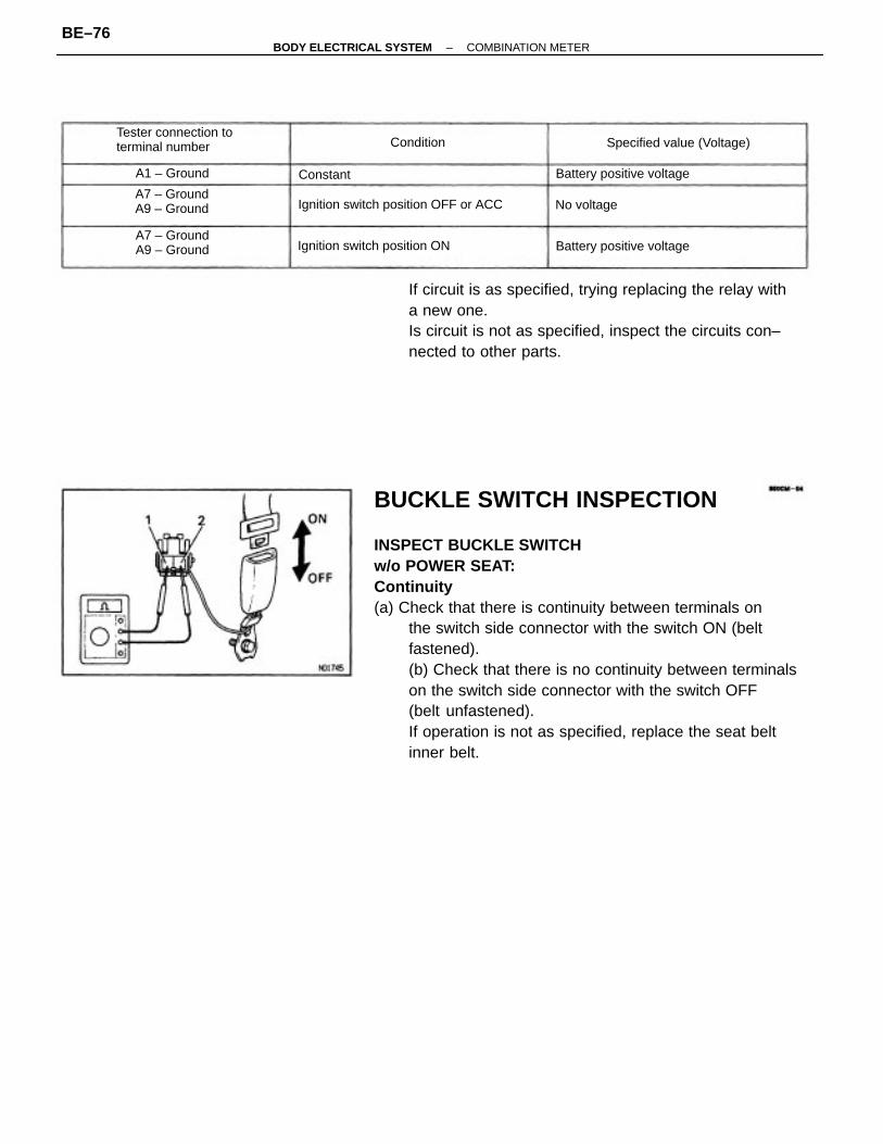
BUCKLE SWITCH INSPECTION
INSPECT BUCKLE SWITCHw/o POWER SEAT:Continuity(a) Check that there is continuity between terminals on
the switch side connector with the switch ON (beltfastened).(b) Check that there is no continuity between terminalson the switch side connector with the switch OFF(belt unfastened).If operation is not as specified, replace the seat beltinner belt.
If circuit is as specified, trying replacing the relay witha new one.Is circuit is not as specified, inspect the circuits con–nected to other parts.
Tester connection toterminal number
Ignition switch position OFF or ACC
Ignition switch position ON
A7 – GroundA9 – Ground
A7 – GroundA9 – Ground
Specified value (Voltage)
Battery positive voltage
Battery positive voltage
A1 – Ground
No voltage
Condition
Constant
–BODY ELECTRICAL SYSTEM COMBINATION METERBE–76
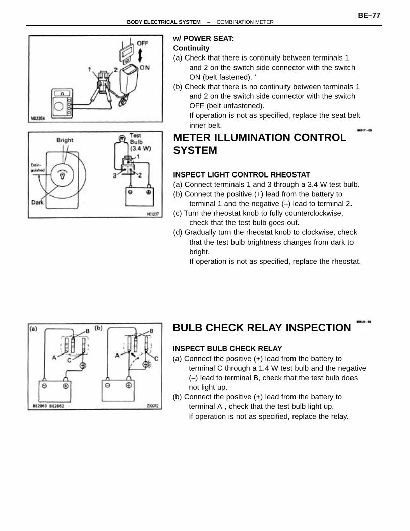
w/ POWER SEAT:Continuity(a) Check that there is continuity between terminals 1
and 2 on the switch side connector with the switchON (belt fastened). ’
(b) Check that there is no continuity between terminals 1and 2 on the switch side connector with the switchOFF (belt unfastened).If operation is not as specified, replace the seat beltinner belt.
METER ILLUMINATION CONTROLSYSTEM
INSPECT LIGHT CONTROL RHEOSTAT(a) Connect terminals 1 and 3 through a 3.4 W test bulb.(b) Connect the positive (+) lead from the battery to
terminal 1 and the negative (–) lead to terminal 2.(c) Turn the rheostat knob to fully counterclockwise,
check that the test bulb goes out.(d) Gradually turn the rheostat knob to clockwise, check
that the test bulb brightness changes from dark tobright.If operation is not as specified, replace the rheostat.
BULB CHECK RELAY INSPECTION
INSPECT BULB CHECK RELAY(a) Connect the positive (+) lead from the battery to
terminal C through a 1.4 W test bulb and the negative(–) lead to terminal B, check that the test bulb doesnot light up.
(b) Connect the positive (+) lead from the battery toterminal A , check that the test bulb light up.If operation is not as specified, replace the relay.
–BODY ELECTRICAL SYSTEM COMBINATION METERBE–77
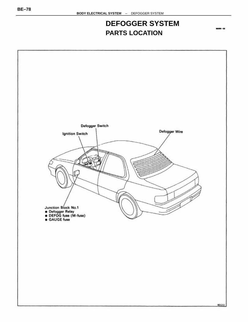
DEFOGGER SYSTEMPARTS LOCATION
–BODY ELECTRICAL SYSTEM DEFOGGER SYSTEMBE–78
TROUBLESHOOTINGThe table below will be useful for you in troubleshooting these electrical problems. The mostlikely causes of the malfunction are shown in the order of their probability. Inspect each part inthe order shown, and replace the part when it is found to be faulty.
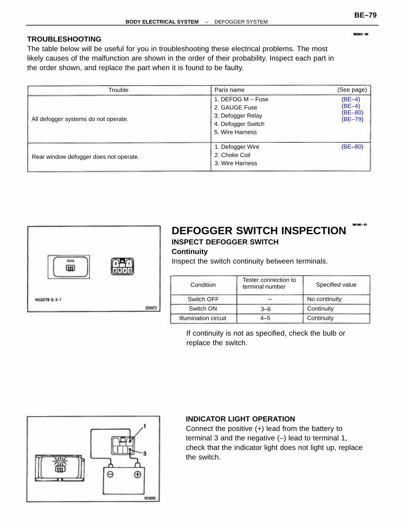
INDICATOR LIGHT OPERATIONConnect the positive (+) lead from the battery toterminal 3 and the negative (–) lead to terminal 1,check that the indicator light does not light up, replacethe switch.
DEFOGGER SWITCH INSPECTIONINSPECT DEFOGGER SWITCHContinuityInspect the switch continuity between terminals.
If continuity is not as specified, check the bulb orreplace the switch.
1. DEFOG M – Fuse2. GAUGE Fuse3. Defogger Relay4. Defogger Switch5. Wire Harness
1. Defogger Wire2. Choke Coil3. Wire Harness
Rear window defogger does not operate.
Tester connection toterminal number
All defogger systems do not operate.
(BE–4)(BE–4)(BE–80)(BE–79)
Illumination circuit
Specified value
No continuity
(See page)
Switch OFF
Paris name
ContinuitySwitch ON
Continuity
(BE–80)
Condition
Trouble
4–5
3–6
–BODY ELECTRICAL SYSTEM DEFOGGER SYSTEMBE–79
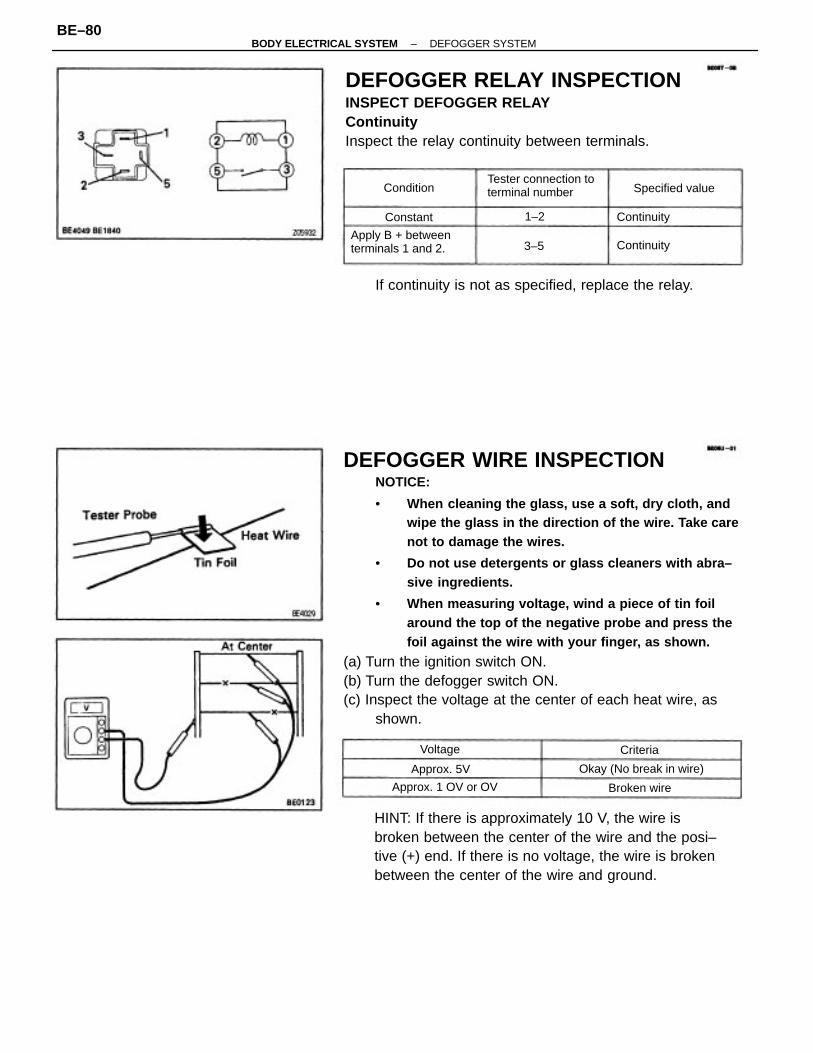
DEFOGGER WIRE INSPECTIONNOTICE:
• When cleaning the glass, use a soft, dry cloth, andwipe the glass in the direction of the wire. Take carenot to damage the wires.
• Do not use detergents or glass cleaners with abra–sive ingredients.
• When measuring voltage, wind a piece of tin foilaround the top of the negative probe and press thefoil against the wire with your finger, as shown.
(a) Turn the ignition switch ON.(b) Turn the defogger switch ON.(c) Inspect the voltage at the center of each heat wire, as
shown.
DEFOGGER RELAY INSPECTIONINSPECT DEFOGGER RELAYContinuityInspect the relay continuity between terminals.
HINT: If there is approximately 10 V, the wire isbroken between the center of the wire and the posi–tive (+) end. If there is no voltage, the wire is brokenbetween the center of the wire and ground.
If continuity is not as specified, replace the relay.
Tester connection toterminal number
Apply B + betweenterminals 1 and 2.
Okay (No break in wire)
Approx. 1 OV or OV
Specified value
Broken wire
Approx. 5V
Continuity
Continuity
Condition
Constant
Voltage Criteria
1–2
3–5
–BODY ELECTRICAL SYSTEM DEFOGGER SYSTEMBE–80
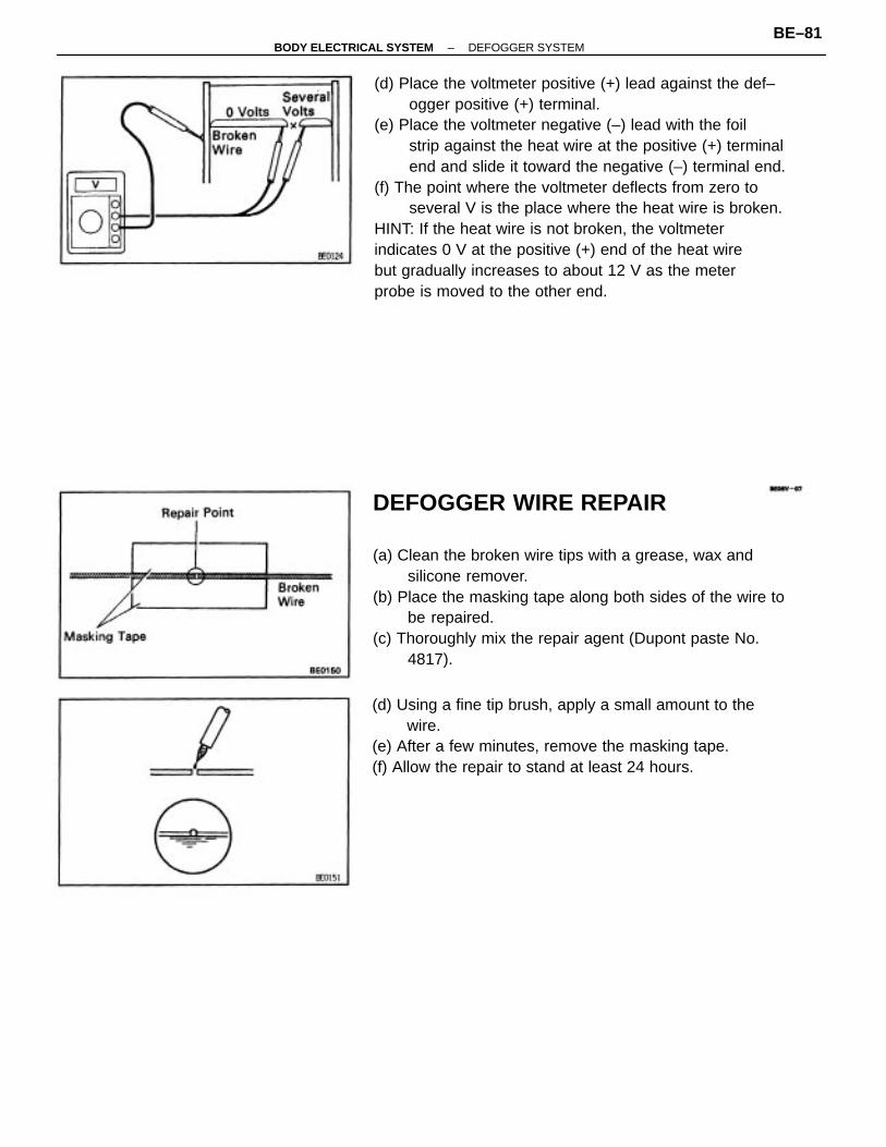
(d) Place the voltmeter positive (+) lead against the def–ogger positive (+) terminal.
(e) Place the voltmeter negative (–) lead with the foilstrip against the heat wire at the positive (+) terminalend and slide it toward the negative (–) terminal end.
(f) The point where the voltmeter deflects from zero toseveral V is the place where the heat wire is broken.
HINT: If the heat wire is not broken, the voltmeterindicates 0 V at the positive (+) end of the heat wirebut gradually increases to about 12 V as the meterprobe is moved to the other end.
DEFOGGER WIRE REPAIR
(a) Clean the broken wire tips with a grease, wax andsilicone remover.
(b) Place the masking tape along both sides of the wire tobe repaired.
(c) Thoroughly mix the repair agent (Dupont paste No.4817).
(d) Using a fine tip brush, apply a small amount to thewire.
(e) After a few minutes, remove the masking tape.(f) Allow the repair to stand at least 24 hours.
–BODY ELECTRICAL SYSTEM DEFOGGER SYSTEMBE–81
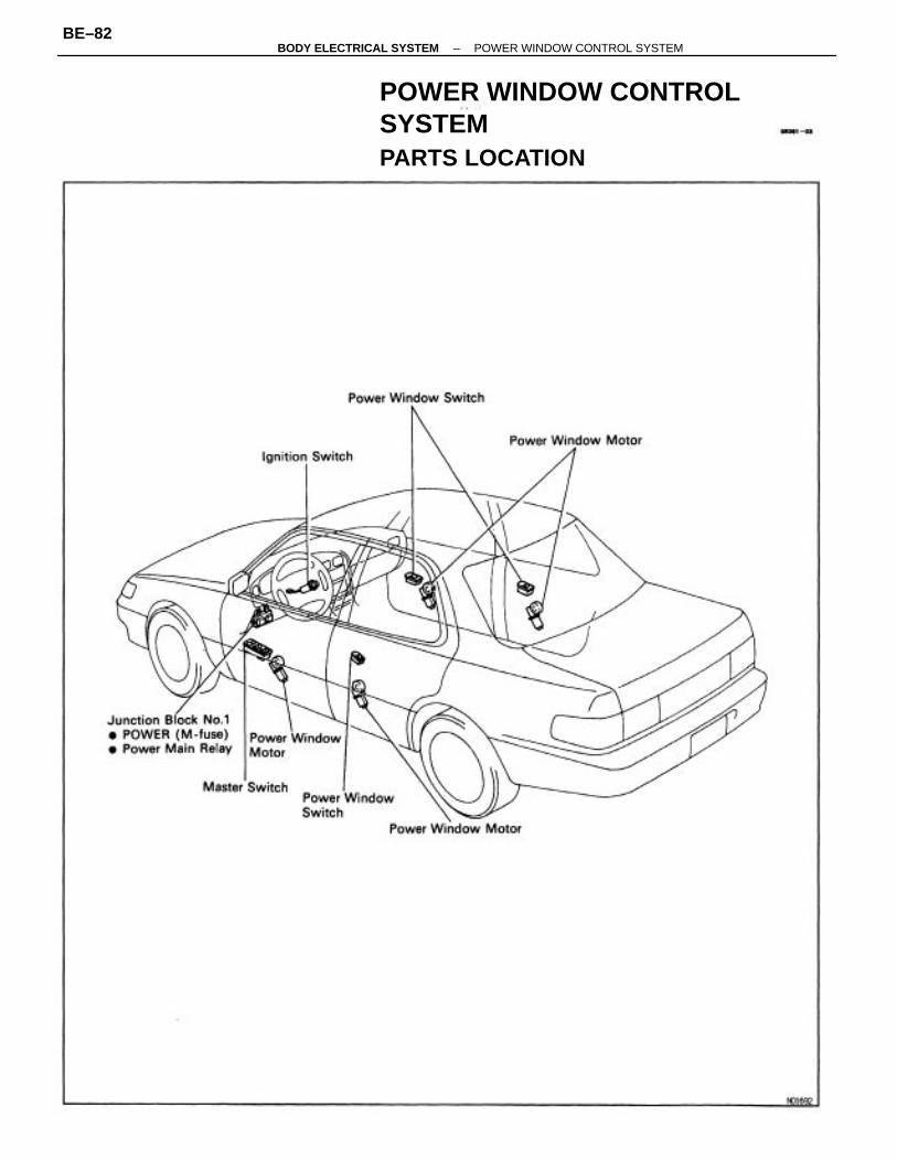
POWER WINDOW CONTROLSYSTEMPARTS LOCATION
–BODY ELECTRICAL SYSTEM POWER WINDOW CONTROL SYSTEMBE–82
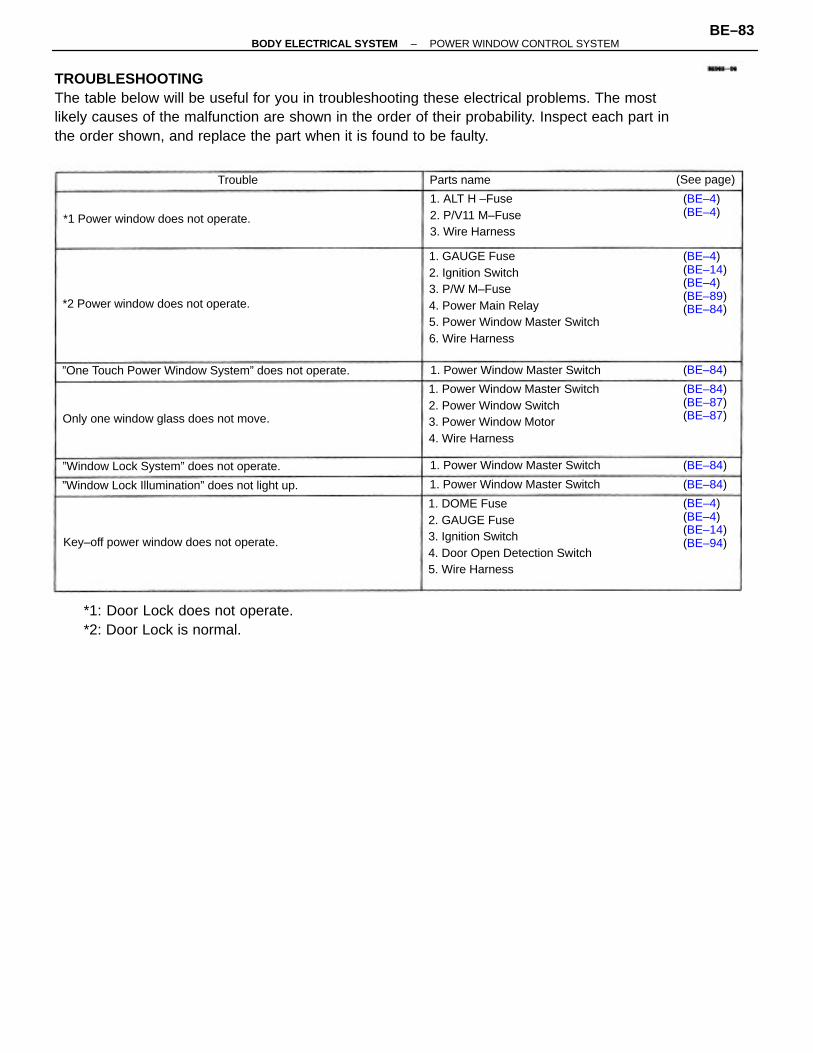
TROUBLESHOOTINGThe table below will be useful for you in troubleshooting these electrical problems. The mostlikely causes of the malfunction are shown in the order of their probability. Inspect each part inthe order shown, and replace the part when it is found to be faulty.
1. GAUGE Fuse2. Ignition Switch3. P/W M–Fuse4. Power Main Relay5. Power Window Master Switch6. Wire Harness
1. DOME Fuse2. GAUGE Fuse3. Ignition Switch4. Door Open Detection Switch5. Wire Harness
1. Power Window Master Switch2. Power Window Switch3. Power Window Motor4. Wire Harness
*1: Door Lock does not operate.*2: Door Lock is normal.
”One Touch Power Window System” does not operate.
1. ALT H –Fuse2. P/V11 M–Fuse3. Wire Harness
”Window Lock Illumination” does not light up.
(BE–4)(BE–14)(BE–4)(BE–89)(BE–84)
Key–off power window does not operate.
”Window Lock System” does not operate.
Only one window glass does not move.
*1 Power window does not operate.
(BE–4)(BE–4)(BE–14)(BE–94)
*2 Power window does not operate.
1. Power Window Master Switch
1. Power Window Master Switch
1. Power Window Master Switch
(BE–84)(BE–87)(BE–87)
(BE–4)(BE–4)
(See page)Parts name
(BE–84)
(BE–84)
(BE–84)
Trouble
–BODY ELECTRICAL SYSTEM POWER WINDOW CONTROL SYSTEMBE–83
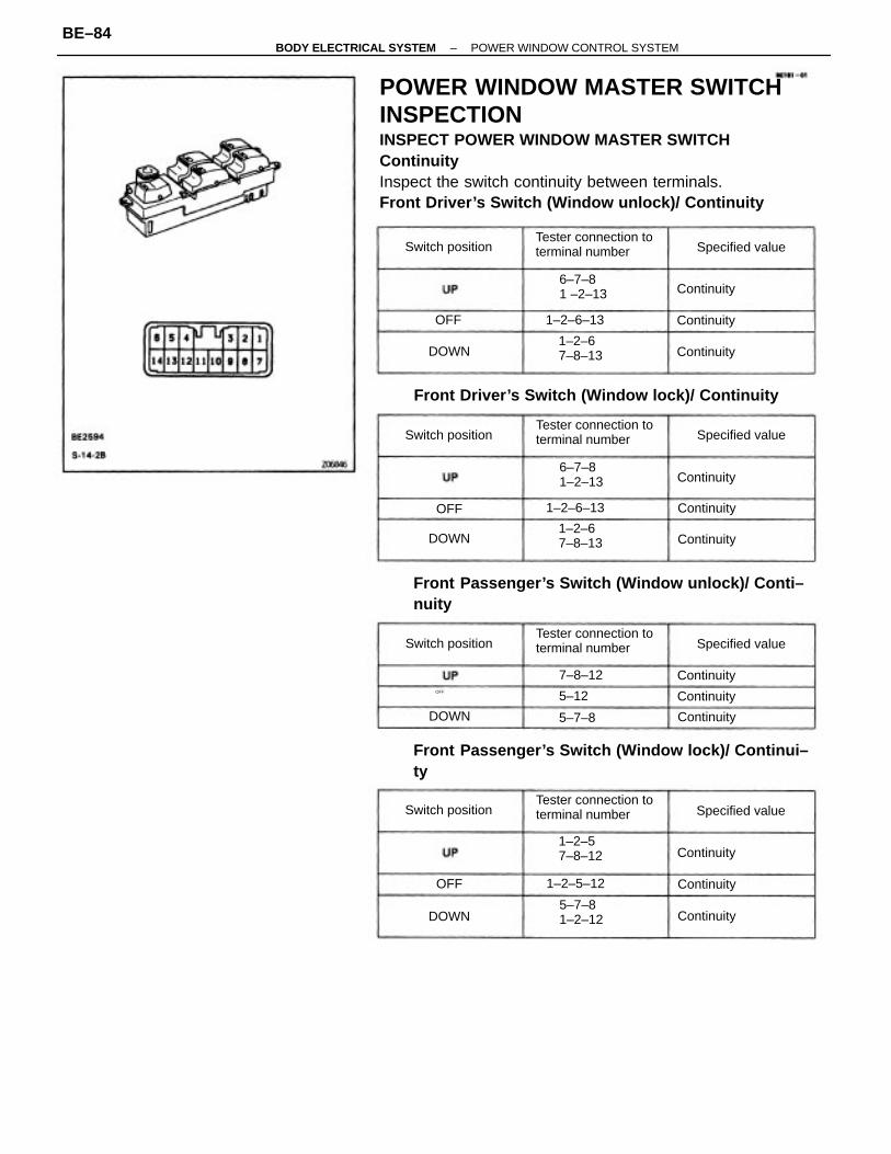
POWER WINDOW MASTER SWITCHINSPECTIONINSPECT POWER WINDOW MASTER SWITCHContinuityInspect the switch continuity between terminals.Front Driver’s Switch (Window unlock)/ Continuity
Front Passenger’s Switch (Window unlock)/ Conti–nuity
Front Passenger’s Switch (Window lock)/ Continui–ty
Front Driver’s Switch (Window lock)/ Continuity
Tester connection toterminal number
Tester connection toterminal number
Tester connection toterminal number
Tester connection toterminal number
1–2–57–8–12
5–7–81–2–12
1–2–67–8–13
1–2–67–8–13
6–7–81 –2–13
6–7–81–2–13
1–2–6–13
1–2–5–12
1–2–6–13
Switch position
Switch position Specified value
Specified value
Specified value
Switch position Specified value
Switch position
7–8–12
Continuity
Continuity
Continuity
Continuity
Continuity
Continuity
Continuity
Continuity
Continuity
Continuity
Continuity
Continuity
5–7–8
5–12
DOWN
DOWN
DOWN
DOWN
OFF
OFF
OFF
OFF
–BODY ELECTRICAL SYSTEM POWER WINDOW CONTROL SYSTEMBE–84
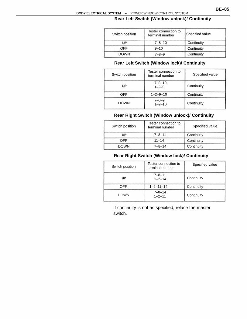
If continuity is not as specified, relace the masterswitch.
Rear Left Switch (Window unlock)/ Continuity
Rear Left Switch (Window lock)/ Continuity
Rear Right Switch (Window unlock)/ Continuity
Rear Right Switch (Window lock)/ Continuity
Tester connection toterminal number
Tester connection toterminal number
Tester connection toterminal number
Tester connection toterminal number
Specified value
7–8–101–2–9
7–8–111–2–14
7–8–91–2–10
7–8–141–2–11
Specified value
1–2–11–14
1–2–9–10
Switch position
Specified valueSwitch position
Switch position
Specified valueSwitch position
7–8–14
7–8–10
7–8–11
Continuity
Continuity
Continuity
Continuity
Continuity
Continuity
Continuity
Continuity
Continuity
Continuity
Continuity
Continuity
7–8–9
11–14
9–10
DOWN
DOWN
DOWN
DOWN
OFF
OFF
OFF
OFF
–BODY ELECTRICAL SYSTEM POWER WINDOW CONTROL SYSTEMBE–85
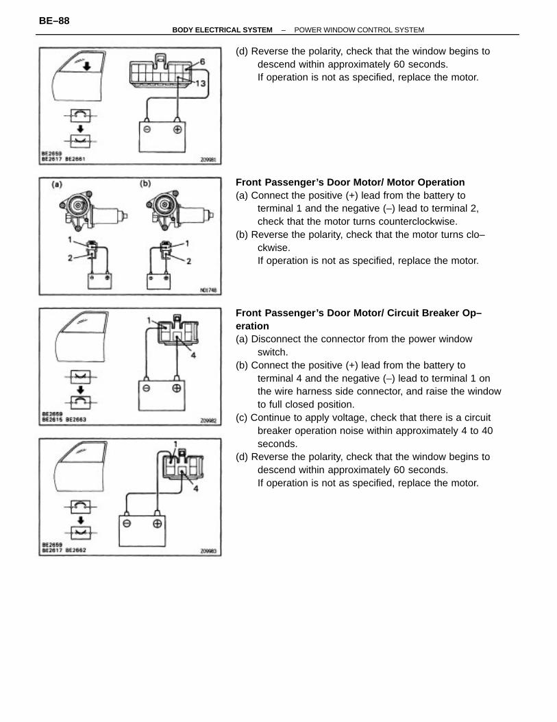
One Touch Power Window System/ Current of Cir–cuitInspection using an ammeter.(a) Disconnect the connector from the master switch.(b) Connect the positive (+) lead from the ammeter to
terminal 6 on the wire harness side connector and thenegative (–) lead to negative terminal of the battery.
(c) Connect the positive (+) lead from the battery toterminal 13 on the wire harness side connector.
(d) As the window goes down, check that the currentflow is approximately 7 A.
(e) Check that the current increases approximately 14.5A or more when the window stops going down.
HINT: The circuit breaker opens some 4 – 40 secondsafter the window stops going down, so that checkmust be made before the circuit breaker operates.If the operation is as specified, replace the masterswitch.
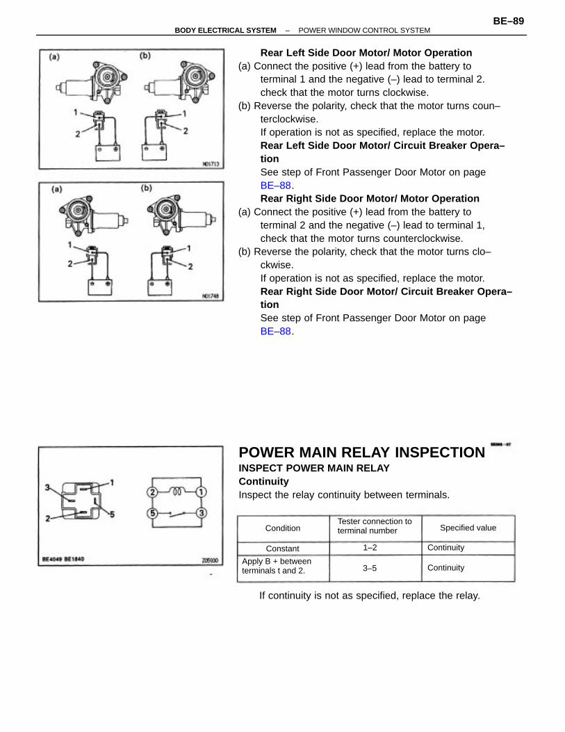
Inspection using an ammeter with a current–meas–uring probe.(a) Remove the master switch with connector connected.(b) Attach a current–measuring probe to terminal 6 of
the wire harness.(c) Turn the ignition switch ON and set the power
window switch in the down position.(d) As the window goes down, check that the current
flow is approximately 7 A.
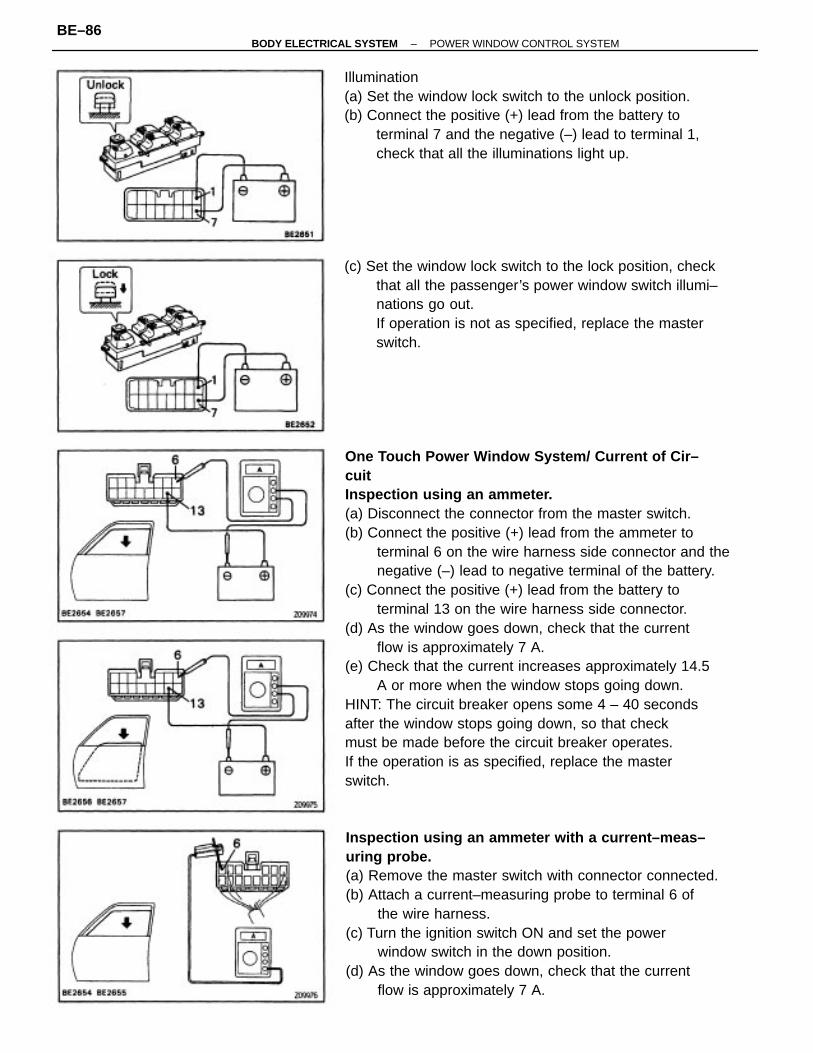
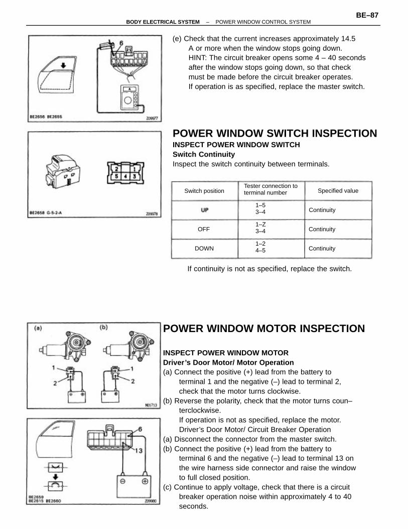
Illumination(a) Set the window lock switch to the unlock position.(b) Connect the positive (+) lead from the battery to
terminal 7 and the negative (–) lead to terminal 1,check that all the illuminations light up.
(c) Set the window lock switch to the lock position, checkthat all the passenger’s power window switch illumi–nations go out.If operation is not as specified, replace the masterswitch.
–BODY ELECTRICAL SYSTEM POWER WINDOW CONTROL SYSTEMBE–86
POWER WINDOW MOTOR INSPECTION
INSPECT POWER WINDOW MOTORDriver’s Door Motor/ Motor Operation(a) Connect the positive (+) lead from the battery to
terminal 1 and the negative (–) lead to terminal 2,check that the motor turns clockwise.
(b) Reverse the polarity, check that the motor turns coun–terclockwise.If operation is not as specified, replace the motor.Driver’s Door Motor/ Circuit Breaker Operation
(a) Disconnect the connector from the master switch.(b) Connect the positive (+) lead from the battery to
terminal 6 and the negative (–) lead to terminal 13 onthe wire harness side connector and raise the windowto full closed position.
(c) Continue to apply voltage, check that there is a circuitbreaker operation noise within approximately 4 to 40seconds.
(e) Check that the current increases approximately 14.5A or more when the window stops going down.HINT: The circuit breaker opens some 4 – 40 secondsafter the window stops going down, so that checkmust be made before the circuit breaker operates.If operation is as specified, replace the master switch.
POWER WINDOW SWITCH INSPECTIONINSPECT POWER WINDOW SWITCHSwitch ContinuityInspect the switch continuity between terminals.
If continuity is not as specified, replace the switch.
Tester connection toterminal number
1–Z3–4
Specified valueSwitch position
1–53–4
1–24–5
Continuity
Continuity
ContinuityDOWN
OFF
–BODY ELECTRICAL SYSTEM POWER WINDOW CONTROL SYSTEMBE–87
Front Passenger’s Door Motor/ Circuit Breaker Op–eration(a) Disconnect the connector from the power window
switch.(b) Connect the positive (+) lead from the battery to
terminal 4 and the negative (–) lead to terminal 1 onthe wire harness side connector, and raise the windowto full closed position.
(c) Continue to apply voltage, check that there is a circuitbreaker operation noise within approximately 4 to 40seconds.
(d) Reverse the polarity, check that the window begins todescend within approximately 60 seconds.If operation is not as specified, replace the motor.
Front Passenger’s Door Motor/ Motor Operation(a) Connect the positive (+) lead from the battery to
terminal 1 and the negative (–) lead to terminal 2,check that the motor turns counterclockwise.
(b) Reverse the polarity, check that the motor turns clo–ckwise.If operation is not as specified, replace the motor.
(d) Reverse the polarity, check that the window begins todescend within approximately 60 seconds.If operation is not as specified, replace the motor.
–BODY ELECTRICAL SYSTEM POWER WINDOW CONTROL SYSTEMBE–88
Rear Left Side Door Motor/ Motor Operation(a) Connect the positive (+) lead from the battery to
terminal 1 and the negative (–) lead to terminal 2.check that the motor turns clockwise.
(b) Reverse the polarity, check that the motor turns coun–terclockwise.If operation is not as specified, replace the motor.Rear Left Side Door Motor/ Circuit Breaker Opera–tionSee step of Front Passenger Door Motor on page BE–88.Rear Right Side Door Motor/ Motor Operation
(a) Connect the positive (+) lead from the battery toterminal 2 and the negative (–) lead to terminal 1,check that the motor turns counterclockwise.
(b) Reverse the polarity, check that the motor turns clo–ckwise.If operation is not as specified, replace the motor.Rear Right Side Door Motor/ Circuit Breaker Opera–tionSee step of Front Passenger Door Motor on page BE–88.
POWER MAIN RELAY INSPECTIONINSPECT POWER MAIN RELAYContinuityInspect the relay continuity between terminals.
If continuity is not as specified, replace the relay.
Tester connection toterminal number
Apply B + betweenterminals t and 2.
Specified value
Continuity
Continuity
Condition
Constant 1–2
3–5
–BODY ELECTRICAL SYSTEM POWER WINDOW CONTROL SYSTEMBE–89
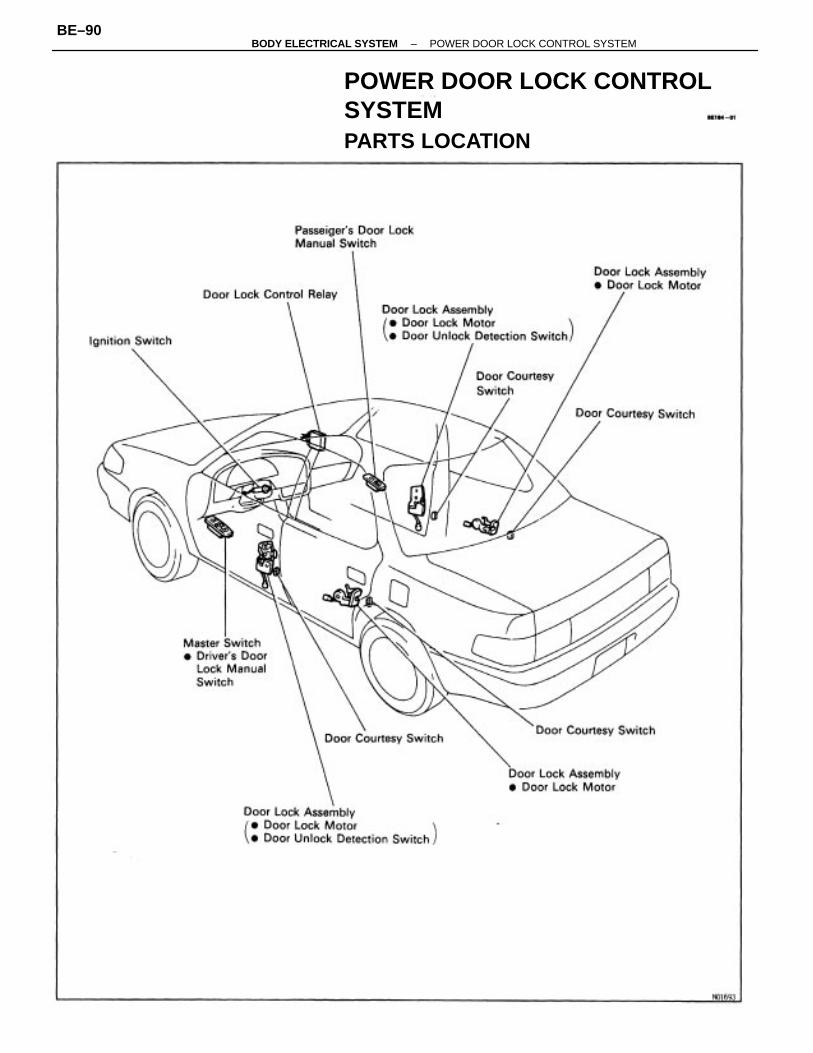
POWER DOOR LOCK CONTROLSYSTEMPARTS LOCATION
–BODY ELECTRICAL SYSTEM POWER DOOR LOCK CONTROL SYSTEMBE–90
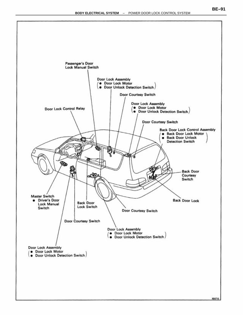
–BODY ELECTRICAL SYSTEM POWER DOOR LOCK CONTROL SYSTEMBE–91
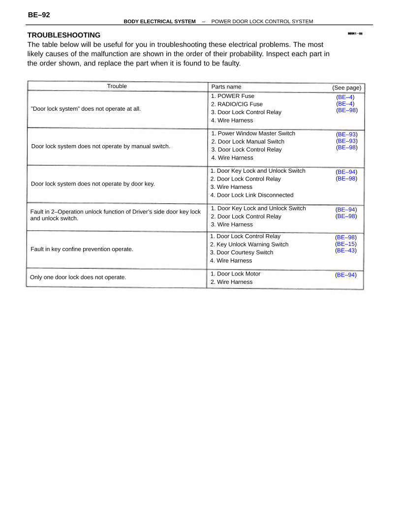
TROUBLESHOOTINGThe table below will be useful for you in troubleshooting these electrical problems. The mostlikely causes of the malfunction are shown in the order of their probability. Inspect each part inthe order shown, and replace the part when it is found to be faulty.
1. Door Key Lock and Unlock Switch2. Door Lock Control Relay3. Wire Harness4. Door Lock Link Disconnected
Fault in 2–Operation unlock function of Driver’s side door key lockand unlock switch.
1. Power Window Master Switch2. Door Lock Manual Switch3. Door Lock Control Relay4. Wire Harness
1. Door Lock Control Relay2. Key Unlock Warning Switch3. Door Courtesy Switch4. Wire Harness
1. Door Key Lock and Unlock Switch2. Door Lock Control Relay3. Wire Harness
1. POWER Fuse2. RADIO/CIG Fuse3. Door Lock Control Relay4. Wire Harness
Door lock system does not operate by manual switch.
Door lock system does not operate by door key.
”Door lock system” does not operate at all.
Fault in key confine prevention operate.
Only one door lock does not operate.1. Door Lock Motor2. Wire Harness
(BE–98)(BE–15)(BE–43)
(BE–93)(BE–93)(BE–98)
(BE–4)(BE–4)(BE–98)
(BE–94)(BE–98)
(BE–94)(BE–98)
(See page)Parts name
(BE–94)
Trouble
–BODY ELECTRICAL SYSTEM POWER DOOR LOCK CONTROL SYSTEMBE–92
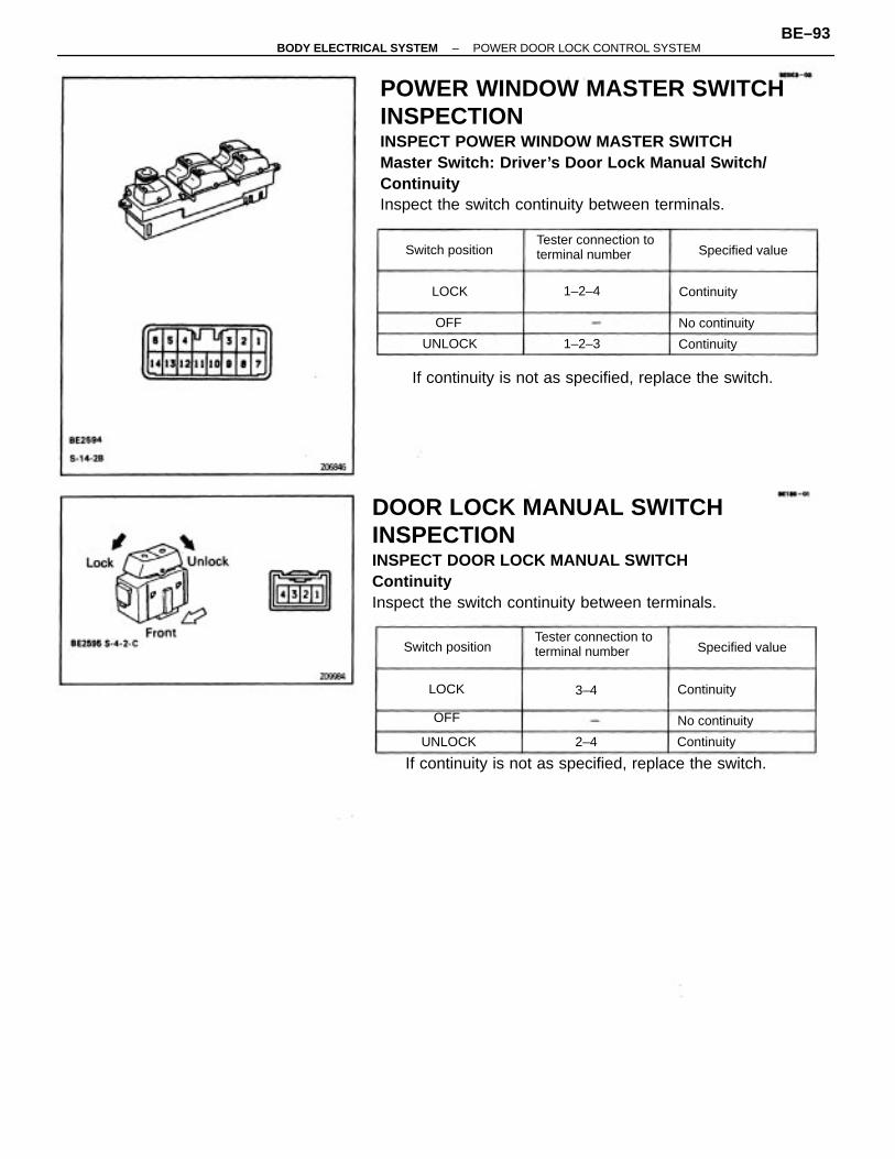
POWER WINDOW MASTER SWITCHINSPECTIONINSPECT POWER WINDOW MASTER SWITCHMaster Switch: Driver’s Door Lock Manual Switch/ContinuityInspect the switch continuity between terminals.
DOOR LOCK MANUAL SWITCHINSPECTIONINSPECT DOOR LOCK MANUAL SWITCHContinuityInspect the switch continuity between terminals.
If continuity is not as specified, replace the switch.
If continuity is not as specified, replace the switch.
Tester connection toterminal number
Tester connection toterminal number
Switch position
Switch position
Specified value
Specified value
No continuity
No continuity
LOCK
1–2–4
1–2–3 Continuity
Continuity
Continuity
ContinuityUNLOCK
UNLOCK
2–4
LOCK
3–4
OFF
OFF
–BODY ELECTRICAL SYSTEM POWER DOOR LOCK CONTROL SYSTEMBE–93
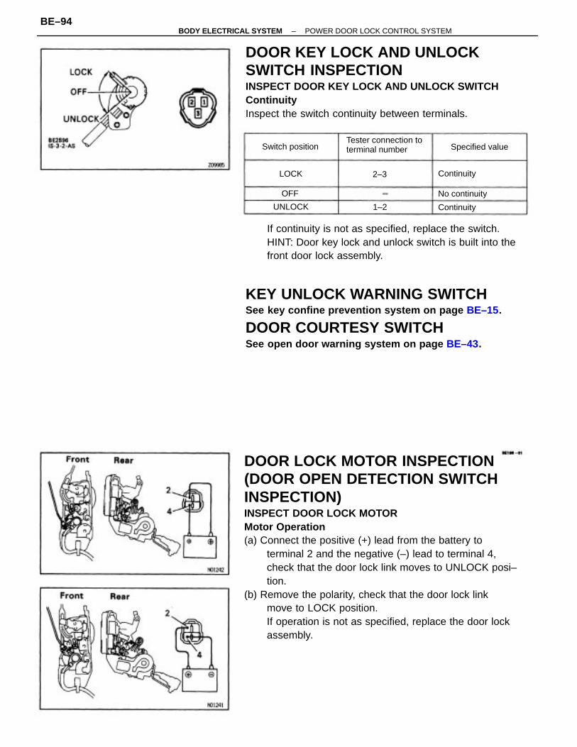
DOOR LOCK MOTOR INSPECTION(DOOR OPEN DETECTION SWITCHINSPECTION)INSPECT DOOR LOCK MOTORMotor Operation(a) Connect the positive (+) lead from the battery to
terminal 2 and the negative (–) lead to terminal 4,check that the door lock link moves to UNLOCK posi–tion.
(b) Remove the polarity, check that the door lock linkmove to LOCK position.If operation is not as specified, replace the door lockassembly.
DOOR KEY LOCK AND UNLOCKSWITCH INSPECTIONINSPECT DOOR KEY LOCK AND UNLOCK SWITCHContinuityInspect the switch continuity between terminals.
KEY UNLOCK WARNING SWITCHSee key confine prevention system on page BE–15.
DOOR COURTESY SWITCHSee open door warning system on page BE–43.
If continuity is not as specified, replace the switch.HINT: Door key lock and unlock switch is built into thefront door lock assembly.
Tester connection toterminal numberSwitch position Specified value
No continuity
Continuity
Continuity
UNLOCK 1–2
2–3LOCK
OFF
–BODY ELECTRICAL SYSTEM POWER DOOR LOCK CONTROL SYSTEMBE–94
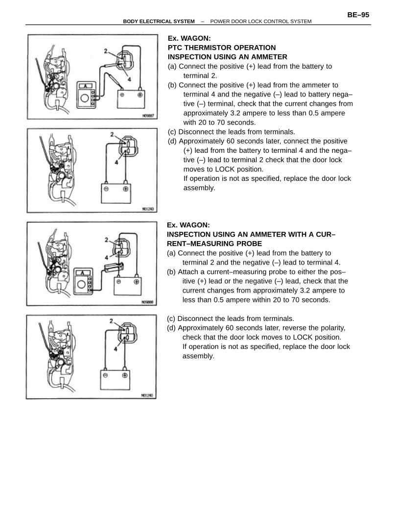
Ex. WAGON:PTC THERMISTOR OPERATIONINSPECTION USING AN AMMETER(a) Connect the positive (+) lead from the battery to
terminal 2.(b) Connect the positive (+) lead from the ammeter to
terminal 4 and the negative (–) lead to battery nega–tive (–) terminal, check that the current changes fromapproximately 3.2 ampere to less than 0.5 amperewith 20 to 70 seconds.
(c) Disconnect the leads from terminals.(d) Approximately 60 seconds later, connect the positive
(+) lead from the battery to terminal 4 and the nega–tive (–) lead to terminal 2 check that the door lockmoves to LOCK position.If operation is not as specified, replace the door lockassembly.
Ex. WAGON:INSPECTION USING AN AMMETER WITH A CUR–RENT–MEASURING PROBE(a) Connect the positive (+) lead from the battery to
terminal 2 and the negative (–) lead to terminal 4.(b) Attach a current–measuring probe to either the pos–
itive (+) lead or the negative (–) lead, check that thecurrent changes from approximately 3.2 ampere toless than 0.5 ampere within 20 to 70 seconds.
(c) Disconnect the leads from terminals.(d) Approximately 60 seconds later, reverse the polarity,
check that the door lock moves to LOCK position.If operation is not as specified, replace the door lockassembly.
–BODY ELECTRICAL SYSTEM POWER DOOR LOCK CONTROL SYSTEMBE–95
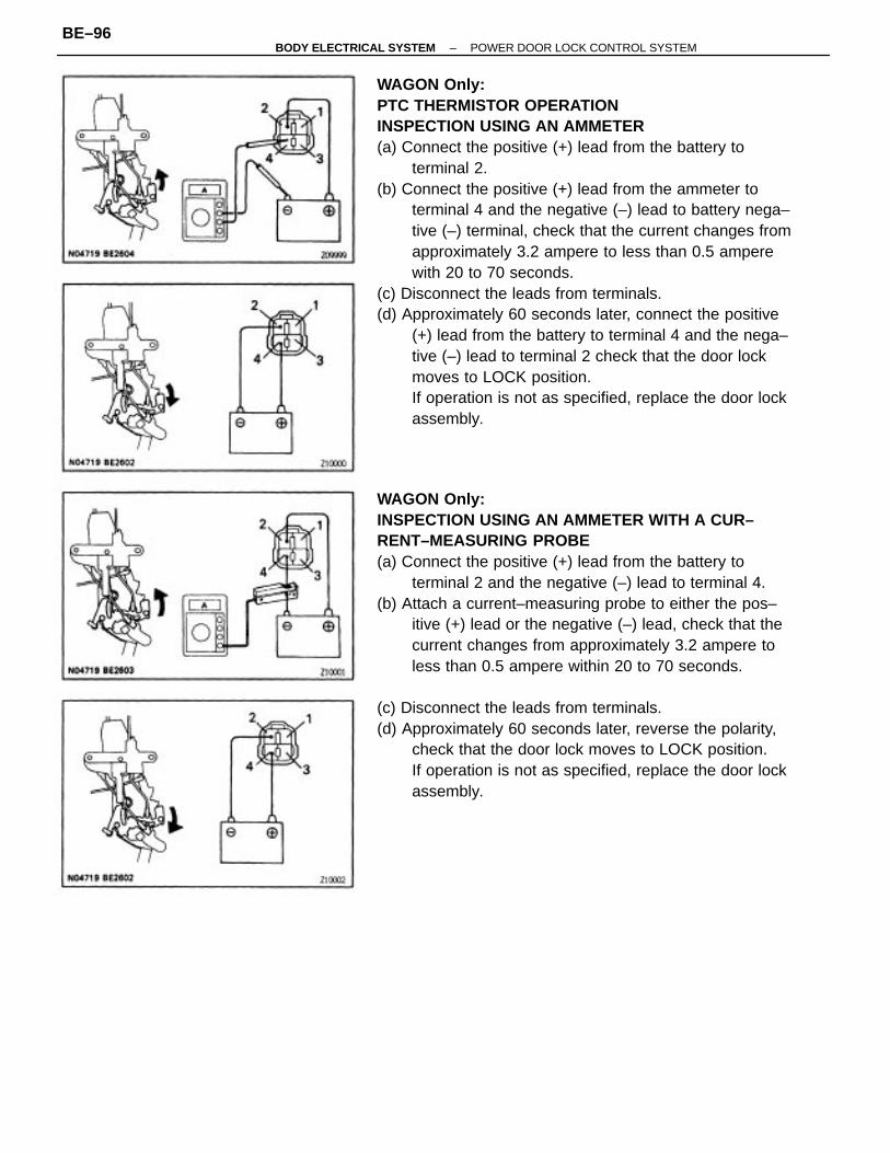
WAGON Only:PTC THERMISTOR OPERATIONINSPECTION USING AN AMMETER(a) Connect the positive (+) lead from the battery to
terminal 2.(b) Connect the positive (+) lead from the ammeter to
terminal 4 and the negative (–) lead to battery nega–tive (–) terminal, check that the current changes fromapproximately 3.2 ampere to less than 0.5 amperewith 20 to 70 seconds.
(c) Disconnect the leads from terminals.(d) Approximately 60 seconds later, connect the positive
(+) lead from the battery to terminal 4 and the nega–tive (–) lead to terminal 2 check that the door lockmoves to LOCK position.If operation is not as specified, replace the door lockassembly.
WAGON Only:INSPECTION USING AN AMMETER WITH A CUR–RENT–MEASURING PROBE(a) Connect the positive (+) lead from the battery to
terminal 2 and the negative (–) lead to terminal 4.(b) Attach a current–measuring probe to either the pos–
itive (+) lead or the negative (–) lead, check that thecurrent changes from approximately 3.2 ampere toless than 0.5 ampere within 20 to 70 seconds.
(c) Disconnect the leads from terminals.(d) Approximately 60 seconds later, reverse the polarity,
check that the door lock moves to LOCK position.If operation is not as specified, replace the door lockassembly.
–BODY ELECTRICAL SYSTEM POWER DOOR LOCK CONTROL SYSTEMBE–96
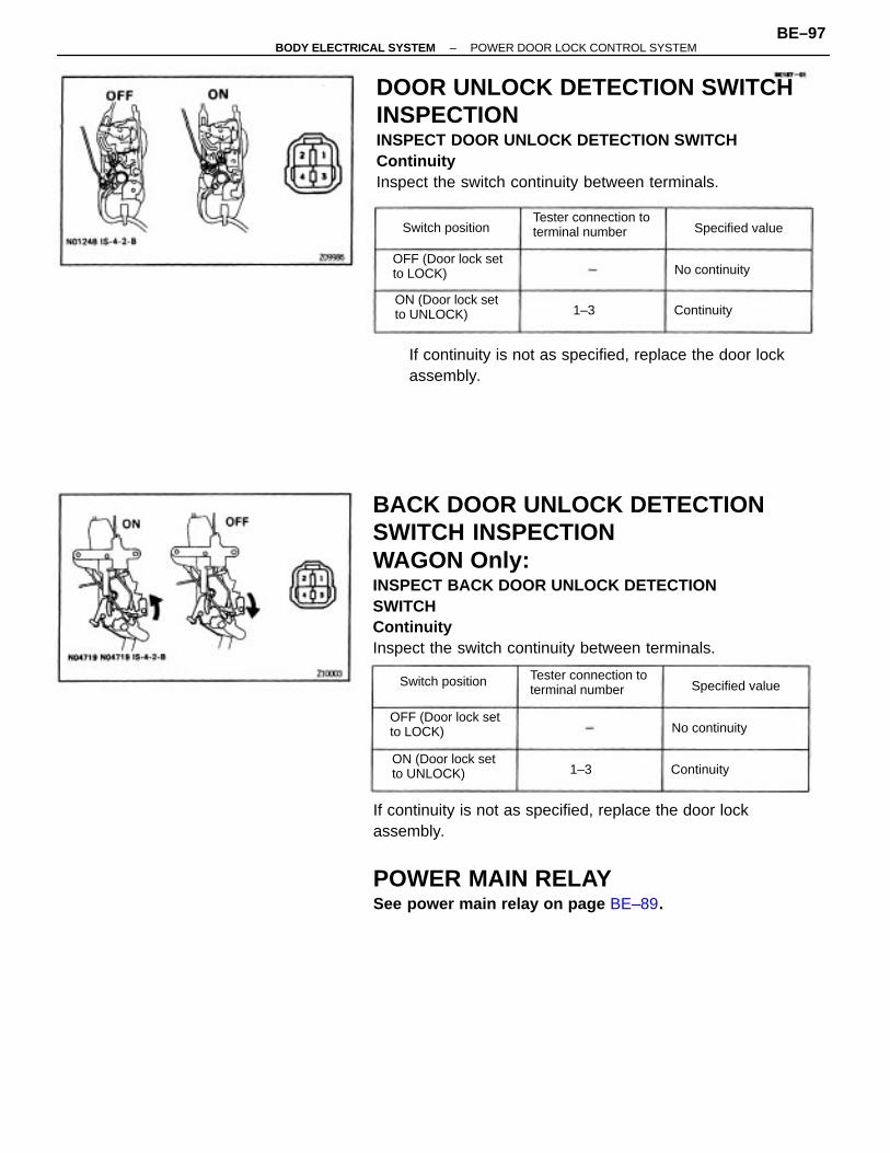
BACK DOOR UNLOCK DETECTIONSWITCH INSPECTIONWAGON Only:INSPECT BACK DOOR UNLOCK DETECTIONSWITCHContinuityInspect the switch continuity between terminals.
DOOR UNLOCK DETECTION SWITCHINSPECTIONINSPECT DOOR UNLOCK DETECTION SWITCHContinuityInspect the switch continuity between terminals.
If continuity is not as specified, replace the door lockassembly.
POWER MAIN RELAYSee power main relay on page BE–89.
If continuity is not as specified, replace the door lockassembly.
OFF (Door lock setto LOCK)
Tester connection toterminal number
Tester connection toterminal number
OFF (Door lock setto LOCK)
ON (Door lock setto UNLOCK)
ON (Door lock setto UNLOCK)
Switch position Specified value
Switch position Specified value
No continuity
No continuity
Continuity
Continuity1–3
1–3
–BODY ELECTRICAL SYSTEM POWER DOOR LOCK CONTROL SYSTEMBE–97
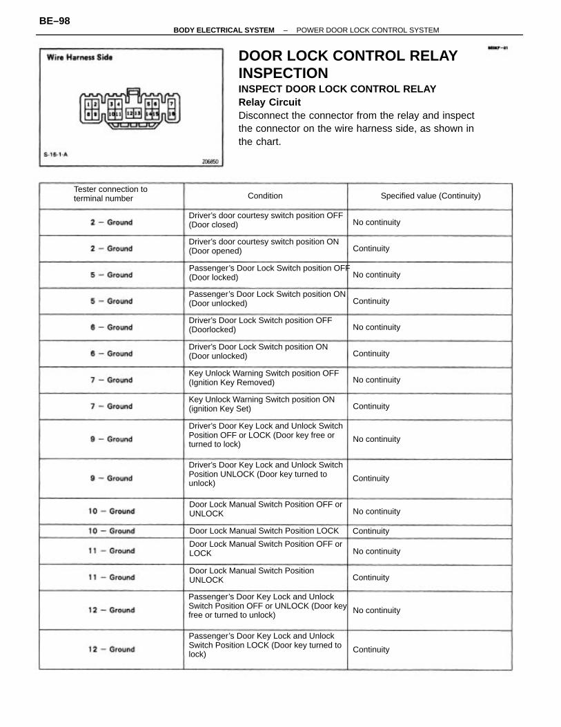
DOOR LOCK CONTROL RELAYINSPECTIONINSPECT DOOR LOCK CONTROL RELAYRelay CircuitDisconnect the connector from the relay and inspectthe connector on the wire harness side, as shown inthe chart.
Driver’s Door Key Lock and Unlock SwitchPosition UNLOCK (Door key turned tounlock)
Driver’s Door Key Lock and Unlock SwitchPosition OFF or LOCK (Door key free orturned to lock)
Passenger’s Door Key Lock and UnlockSwitch Position LOCK (Door key turned tolock)
Passenger’s Door Key Lock and UnlockSwitch Position OFF or UNLOCK (Door keyfree or turned to unlock)
Driver’s Door Lock Switch position ON(Door unlocked)
Driver’s Door Lock Switch position OFF(Doorlocked)
Passenger’s Door Lock Switch position ON(Door unlocked)
Driver’s door courtesy switch position ON(Door opened)
Key Unlock Warning Switch position OFF(Ignition Key Removed)
Key Unlock Warning Switch position ON(ignition Key Set)
Passenger’s Door Lock Switch position OFF(Door locked)
Driver’s door courtesy switch position OFF(Door closed)
Door Lock Manual Switch Position OFF orLOCK
Door Lock Manual Switch Position OFF orUNLOCK
Door Lock Manual Switch PositionUNLOCK
Door Lock Manual Switch Position LOCK
Tester connection toterminal number Specified value (Continuity)
No continuity
No continuity
No continuity
No continuity
No continuity
No continuity
No continuity
No continuity
Continuity
Continuity
Continuity
Continuity
Continuity
Continuity
Continuity
Continuity
Condition
–BODY ELECTRICAL SYSTEM POWER DOOR LOCK CONTROL SYSTEMBE–98
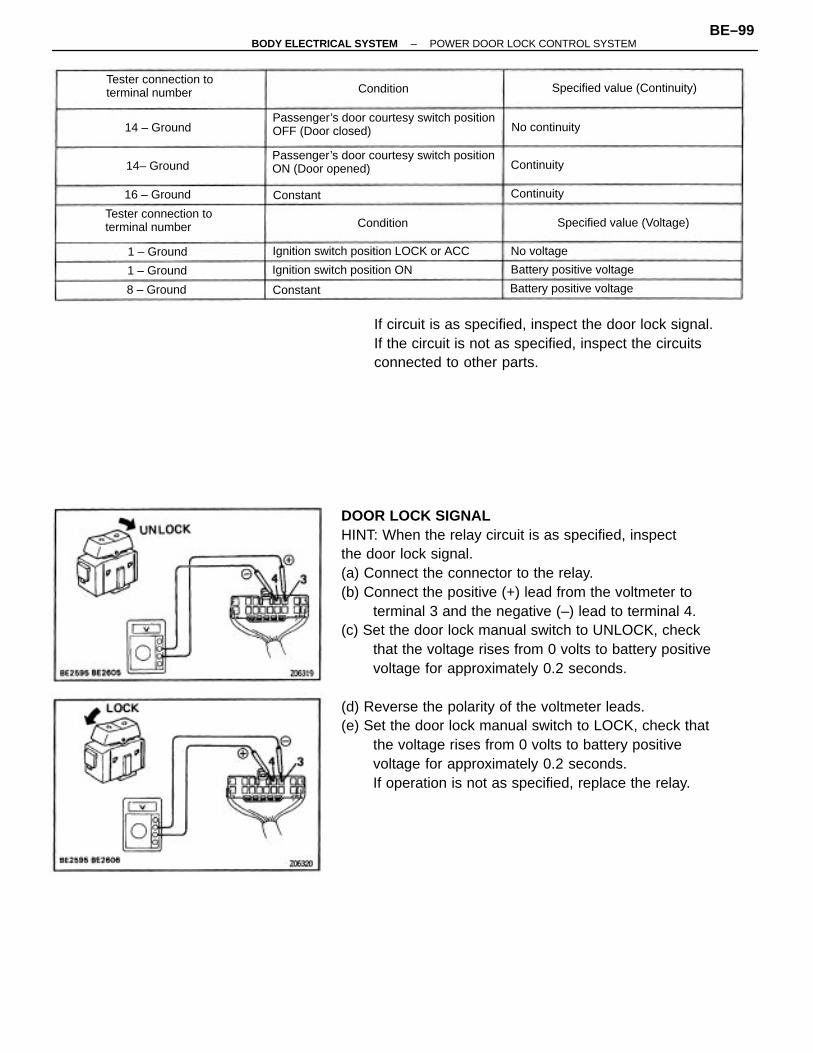
DOOR LOCK SIGNALHINT: When the relay circuit is as specified, inspectthe door lock signal.(a) Connect the connector to the relay.(b) Connect the positive (+) lead from the voltmeter to
terminal 3 and the negative (–) lead to terminal 4.(c) Set the door lock manual switch to UNLOCK, check
that the voltage rises from 0 volts to battery positivevoltage for approximately 0.2 seconds.
(d) Reverse the polarity of the voltmeter leads.(e) Set the door lock manual switch to LOCK, check that
the voltage rises from 0 volts to battery positivevoltage for approximately 0.2 seconds.If operation is not as specified, replace the relay.
If circuit is as specified, inspect the door lock signal.If the circuit is not as specified, inspect the circuitsconnected to other parts.
Passenger’s door courtesy switch positionON (Door opened)
Passenger’s door courtesy switch positionOFF (Door closed)
Tester connection toterminal number
Ignition switch position LOCK or ACC
Tester connection toterminal number Specified value (Continuity)
Ignition switch position ON
Specified value (Voltage)
Battery positive voltage
Battery positive voltage
No continuity
16 – Ground
14 – Ground
14– Ground
1 – Ground
8 – Ground
1 – Ground No voltage
Continuity
Continuity
Condition
Condition
Constant
Constant
–BODY ELECTRICAL SYSTEM POWER DOOR LOCK CONTROL SYSTEMBE–99
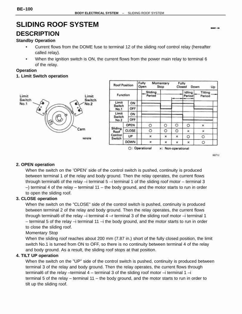
2. OPEN operationWhen the switch on the ’OPEN’ side of the control switch is pushed, continuity is producedbetween terminal 1 of the relay and body ground. Then the relay operates, the current flowsthrough terminal6 of the relay –i terminal 5 –i terminal 1 of the sliding roof motor – terminal 3–) terminal 4 of the relay – terminal 11 – the body ground, and the motor starts to run in orderto open the sliding roof.
3. CLOSE operationWhen the switch on the ”CLOSE” side of the control switch is pushed, continuity is producedbetween terminal 2 of the relay and body ground. Then the relay operates, the current flowsthrough terminal6 of the relay –i terminal 4 –r terminal 3 of the sliding roof motor –i terminal 1– terminal 5 of the relay –i terminal 11 –i the body ground, and the motor starts to run in orderto close the sliding roof.Momentary StopWhen the sliding roof reaches about 200 mm (7.87 in.) short of the fully closed position, the limitswitch No.1 is turned from ON to OFF, so there is no continuity between terminal 4 of the relayand body ground. As a result, the sliding roof stops at that position.
4. TILT UP operationWhen the switch on the ”UP” side of the control switch is pushed, continuity is produced betweenterminal 3 of the relay and body ground. Then the relay operates, the current flows throughterminal6 of the relay –terminal 4 – terminal 3 of the sliding roof motor –i terminal 1 –iterminal 5 of the relay – terminal 11 – the body ground, and the motor starts to run in order totilt up the sliding roof.
SLIDING ROOF SYSTEMDESCRIPTIONStandby Operation
• Current flows from the DOME fuse to terminal 12 of the sliding roof control relay (hereaftercalled relay).
• When the ignition switch is ON, the current flows from the power main relay to terminal 6of the relay.
Operation1. Limit Switch operation
–BODY ELECTRICAL SYSTEM SLIDING ROOF SYSTEMBE–100
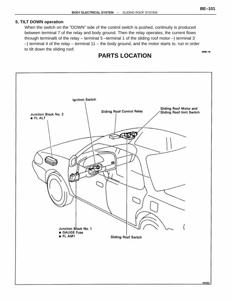
5. TILT DOWN operationWhen the switch on the ”DOWN” side of the control switch is pushed, continuity is producedbetween terminal 7 of the relay and body ground. Then the relay operates, the current flowsthrough terminal6 of the relay – terminal 5 –terminal 1 of the sliding roof motor –) terminal 3–) terminal 4 of the relay – terminal 11 – the body ground, and the motor starts to. run in orderto tilt down the sliding roof.
PARTS LOCATION
–BODY ELECTRICAL SYSTEM SLIDING ROOF SYSTEMBE–101
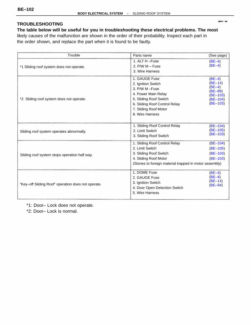
TROUBLESHOOTINGThe table below will be useful for you in troubleshooting these electrical problems. The mostlikely causes of the malfunction are shown in the order of their probability. Inspect each part inthe order shown, and replace the part when it is found to be faulty.
1. Sliding Roof Control Relay (BE–104)2. Limit Switch (BE–105)3. Sliding Roof Switch (BE–103)4. Sliding Roof Motor (BE–103)(Stones to foreign material trapped in motor assembly)
1. GAUGE Fuse2. Ignition Switch3. P/W M –Fuse4. Power Main Relay5. Sliding Roof Switch6. Sliding Roof Control Relay7. Sliding Roof Motor8. Wire Harness
1. DOME Fuse2. GAUGE Fuse3. Ignition Switch4. Door Open Detection Switch5. Wire Harness
*1: Door– Lock does not operate.*2: Door– Lock is normal.
1. Sliding Roof Control Relay2. Limit Switch3. Sliding Roof Switch
(BE–4)(BE–14)(BE–4)(BE–89)(BE–103)(BE–104)(BE–103)
”Key–off Sliding Roof” operation does not operate.
1. ALT H –Fuse2. P/W M – Fuse3. Wire Harness
Sliding roof system stops operation half way.
*2 Sliding roof system does not operate.
*1 Sliding roof system does not operate.
Sliding roof system operates abnormally.
(BE–4)(BE–4)(BE–14)(BE–94)
(BE–104)(BE–105)(BE–103)
(BE–4)(BE–4)
(See page)Parts nameTrouble
–BODY ELECTRICAL SYSTEM SLIDING ROOF SYSTEMBE–102
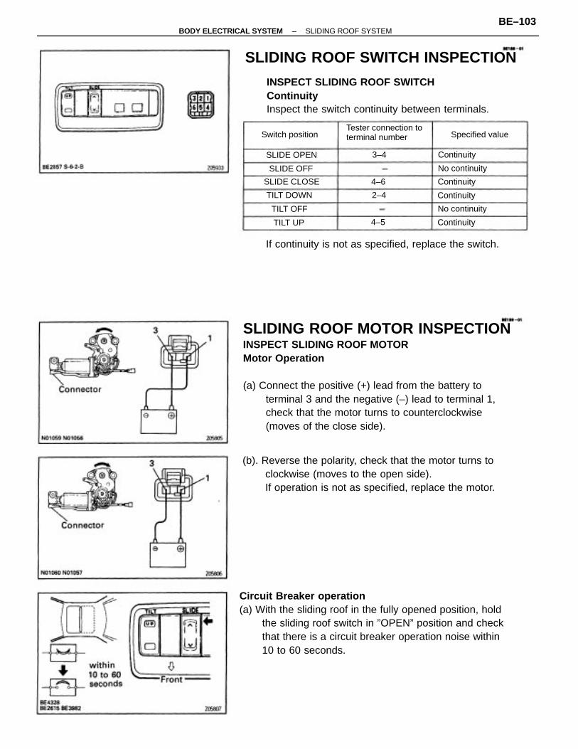
SLIDING ROOF MOTOR INSPECTIONINSPECT SLIDING ROOF MOTORMotor Operation
(a) Connect the positive (+) lead from the battery toterminal 3 and the negative (–) lead to terminal 1,check that the motor turns to counterclockwise(moves of the close side).
Circuit Breaker operation(a) With the sliding roof in the fully opened position, hold
the sliding roof switch in ”OPEN” position and checkthat there is a circuit breaker operation noise within10 to 60 seconds.
(b). Reverse the polarity, check that the motor turns toclockwise (moves to the open side).If operation is not as specified, replace the motor.
INSPECT SLIDING ROOF SWITCHContinuityInspect the switch continuity between terminals.
If continuity is not as specified, replace the switch.
SLIDING ROOF SWITCH INSPECTION
Tester connection toterminal numberSwitch position Specified value
No continuity
No continuity
SLIDE CLOSE
TILT DOWN
SLIDE OPEN
SLIDE OFF
Continuity
Continuity
Continuity
Continuity
TILT OFF
TILT UP
2–4
4–6
3–4
4–5
–BODY ELECTRICAL SYSTEM SLIDING ROOF SYSTEMBE–103
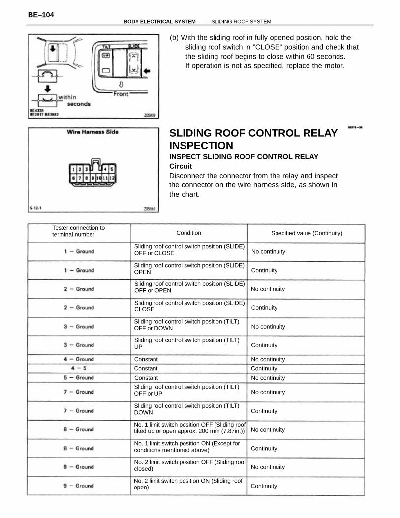
SLIDING ROOF CONTROL RELAYINSPECTIONINSPECT SLIDING ROOF CONTROL RELAYCircuitDisconnect the connector from the relay and inspectthe connector on the wire harness side, as shown inthe chart.
(b) With the sliding roof in fully opened position, hold thesliding roof switch in ”CLOSE” position and check thatthe sliding roof begins to close within 60 seconds.If operation is not as specified, replace the motor.
No. 1 limit switch position OFF (Sliding rooftilted up or open approx. 200 mm (7.87in.))
No. 1 limit switch position ON (Except forconditions mentioned above)
No. 2 limit switch position ON (Sliding roofopen)
No. 2 limit switch position OFF (Sliding roofclosed)
Sliding roof control switch position (TILT)OFF or UP
Sliding roof control switch position (SLIDE)OFF or OPEN
Sliding roof control switch position (SLIDE)CLOSE
Sliding roof control switch position (TILT)OFF or DOWN
Sliding roof control switch position (TILT)UP
Sliding roof control switch position (SLIDE)OPEN
Sliding roof control switch position (SLIDE)OFF or CLOSE
Sliding roof control switch position (TILT)DOWN
Tester connection toterminal number Specified value (Continuity)
No continuity
No continuity
No continuity
No continuity
No continuity
No continuity
No continuity
No continuity
Continuity
Continuity
Continuity
Continuity
Continuity
Continuity
Continuity
Condition
Constant
Constant
Constant
–BODY ELECTRICAL SYSTEM SLIDING ROOF SYSTEMBE–104
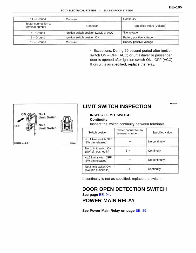
If continuity is not as specified, replace the switch.
DOOR OPEN DETECTION SWITCHSee page BE–94.
POWER MAIN RELAY
See Power Main Relay on page BE–89.
*: Exceptions: During 60 second period after ignitionswitch ON – OFF (ACC) or until driver or passengerdoor is opened after ignition switch ON –OFF (ACC).If circuit is as specified, replace the relay.
INSPECT LIMIT SWITCHContinuityInspect the switch continuity between terminals.
LIMIT SWITCH INSPECTION
No.2 limit switch OFF(SW pin released)
No. 1 limit switch OFF(SW pin released)
No.2 limit switch ON(SW pin pushed in)
No. 1 limit switch ON(SW pin pushed in)
Ignition switch position LOCK or ACC
Tester connection toterminal number
Tester connection toterminal number
Ignition switch position ON
Specified value (Voltage)
Battery positive voltage
Battery positive voltage
Specified valueSwitch position
No continuity
No continuity
12 – Ground
11 – Ground
6 – Ground *No voltage
6 – Ground
Continuity
Continuity
Continuity
Condition
Constant
Constant
1–4
2–4
–BODY ELECTRICAL SYSTEM SLIDING ROOF SYSTEMBE–105
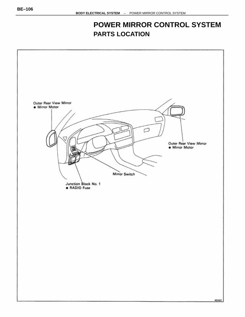
POWER MIRROR CONTROL SYSTEMPARTS LOCATION
–BODY ELECTRICAL SYSTEM POWER MIRROR CONTROL SYSTEMBE–106
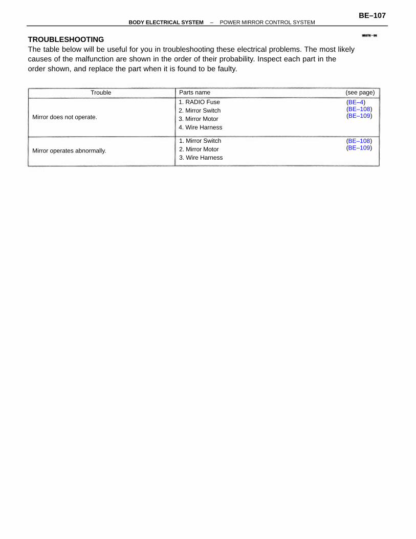
TROUBLESHOOTINGThe table below will be useful for you in troubleshooting these electrical problems. The most likelycauses of the malfunction are shown in the order of their probability. Inspect each part in theorder shown, and replace the part when it is found to be faulty.
1. RADIO Fuse2. Mirror Switch3. Mirror Motor4. Wire Harness
1. Mirror Switch2. Mirror Motor3. Wire Harness
(BE–4)(BE–108)(BE–109)
Mirror operates abnormally.
Mirror does not operate.
(BE–108)(BE–109)
(see page)Parts nameTrouble
–BODY ELECTRICAL SYSTEM POWER MIRROR CONTROL SYSTEMBE–107
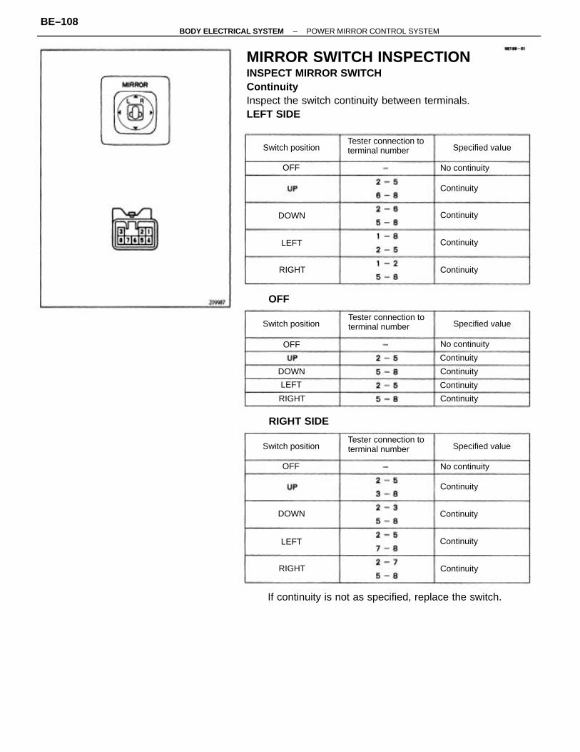
MIRROR SWITCH INSPECTIONINSPECT MIRROR SWITCHContinuityInspect the switch continuity between terminals.LEFT SIDE
If continuity is not as specified, replace the switch.
Tester connection toterminal number
Tester connection toterminal number
Tester connection toterminal number
RIGHT SIDE
Specified value
Switch position Specified value
Specified vaIueSwitch position
Switch position
No continuity
No continuity
No continuity
Continuity
Continuity
Continuity
Continuity
Continuity
Continuity
Continuity
Continuity
Continuity
Continuity
Continuity
Continuity
DOWN
DOWN
RIGHT
RIGHT
RIGHT
DOWN
OFF
LEFT
LEFT
LEFT
OFF
OFF
OFF
–BODY ELECTRICAL SYSTEM POWER MIRROR CONTROL SYSTEMBE–108
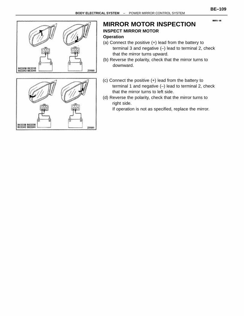
MIRROR MOTOR INSPECTIONINSPECT MIRROR MOTOROperation(a) Connect the positive (+) lead from the battery to
terminal 3 and negative (–) lead to terminal 2, checkthat the mirror turns upward.
(b) Reverse the polarity, check that the mirror turns todownward.
(c) Connect the positive (+) lead from the battery toterminal 1 and negative (–) lead to terminal 2, checkthat the mirror turns to left side.
(d) Reverse the polarity, check that the mirror turns toright side.If operation is not as specified, replace the mirror.
–BODY ELECTRICAL SYSTEM POWER MIRROR CONTROL SYSTEMBE–109
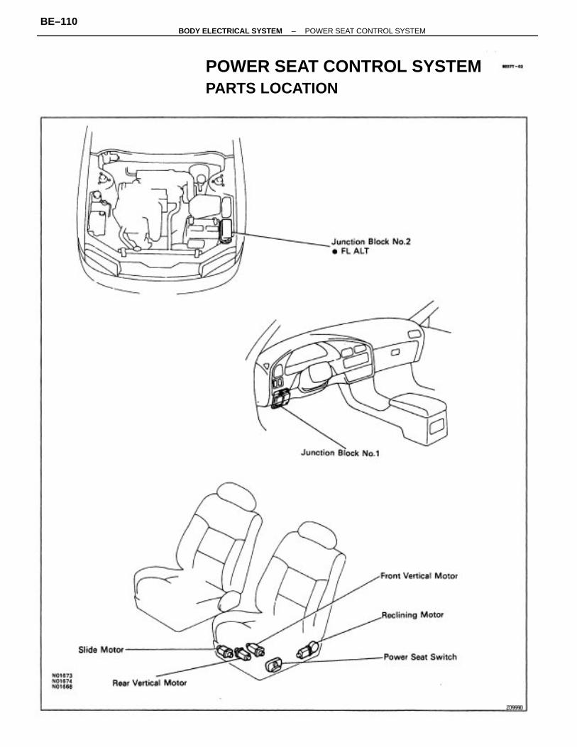
POWER SEAT CONTROL SYSTEMPARTS LOCATION
–BODY ELECTRICAL SYSTEM POWER SEAT CONTROL SYSTEMBE–110
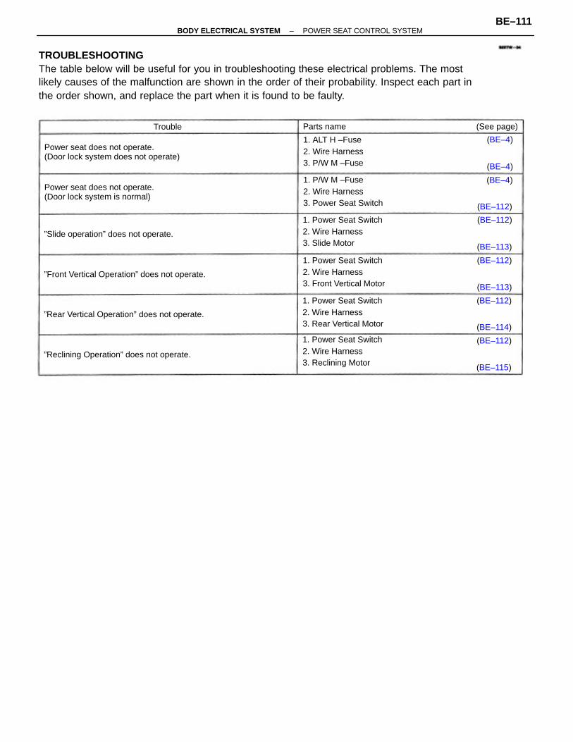
TROUBLESHOOTINGThe table below will be useful for you in troubleshooting these electrical problems. The mostlikely causes of the malfunction are shown in the order of their probability. Inspect each part inthe order shown, and replace the part when it is found to be faulty.
Power seat does not operate.(Door lock system does not operate)
1. Power Seat Switch2. Wire Harness3. Front Vertical Motor
1. Power Seat Switch2. Wire Harness3. Reclining Motor
1. Power Seat Switch2. Wire Harness3. Rear Vertical Motor
1. Power Seat Switch2. Wire Harness3. Slide Motor
1. P/W M –Fuse2. Wire Harness3. Power Seat Switch
Power seat does not operate.(Door lock system is normal)
1. ALT H –Fuse2. Wire Harness3. P/W M –Fuse
”Front Vertical Operation” does not operate.
”Rear Vertical Operation” does not operate.
”Reclining Operation” does not operate.
”Slide operation” does not operate.
(See page)Parts name
(BE–112)
(BE–112)
(BE–112)
(BE–112)
(BE–112)
(BE–115)
(BE–113)
(BE–113)
(BE–114)
(BE–4)
(BE–4)
(BE–4)
Trouble
–BODY ELECTRICAL SYSTEM POWER SEAT CONTROL SYSTEMBE–111
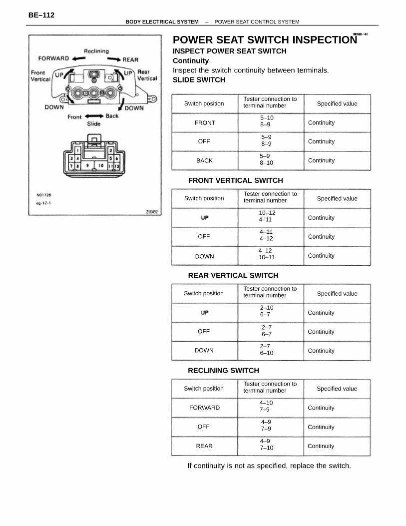
POWER SEAT SWITCH INSPECTIONINSPECT POWER SEAT SWITCHContinuityInspect the switch continuity between terminals.SLIDE SWITCH
If continuity is not as specified, replace the switch.
FRONT VERTICAL SWITCH
REAR VERTICAL SWITCH
Tester connection toterminal number
Tester connection toterminal number
Tester connection toterminal number
Tester connection toterminal number
RECLINING SWITCH
10–124–11
4–1210–11
Specified value
Switch position Specified value
Switch position
Specified value
Specified value
Switch position
4–107–9
Switch position
4–97–10
2–106–7
5–108–9
5–98–10
4–114–12
2–76–10
4–97–9
5–98–9
2–76–7
FORWARD
Continuity
Continuity
Continuity
Continuity
Continuity
Continuity
Continuity
DOWN
Continuity
Continuity
Continuity
Continuity
Continuity
DOWN
FRONT
BACK
REAR
OFF
OFF
OFF
OFF
–BODY ELECTRICAL SYSTEM POWER SEAT CONTROL SYSTEMBE–112
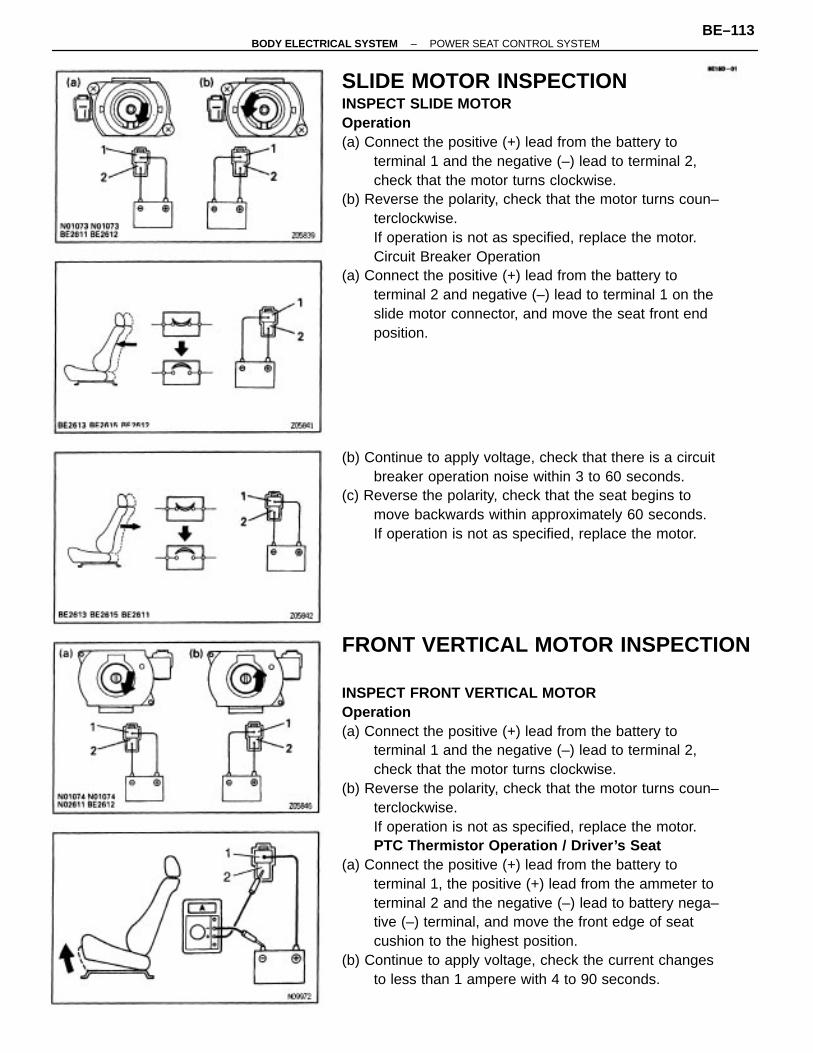
FRONT VERTICAL MOTOR INSPECTION
INSPECT FRONT VERTICAL MOTOROperation(a) Connect the positive (+) lead from the battery to
terminal 1 and the negative (–) lead to terminal 2,check that the motor turns clockwise.
(b) Reverse the polarity, check that the motor turns coun–terclockwise.If operation is not as specified, replace the motor.PTC Thermistor Operation / Driver’s Seat
(a) Connect the positive (+) lead from the battery toterminal 1, the positive (+) lead from the ammeter toterminal 2 and the negative (–) lead to battery nega–tive (–) terminal, and move the front edge of seatcushion to the highest position.
(b) Continue to apply voltage, check the current changesto less than 1 ampere with 4 to 90 seconds.
SLIDE MOTOR INSPECTIONINSPECT SLIDE MOTOROperation(a) Connect the positive (+) lead from the battery to
terminal 1 and the negative (–) lead to terminal 2,check that the motor turns clockwise.
(b) Reverse the polarity, check that the motor turns coun–terclockwise.If operation is not as specified, replace the motor.Circuit Breaker Operation
(a) Connect the positive (+) lead from the battery toterminal 2 and negative (–) lead to terminal 1 on theslide motor connector, and move the seat front endposition.
(b) Continue to apply voltage, check that there is a circuitbreaker operation noise within 3 to 60 seconds.
(c) Reverse the polarity, check that the seat begins tomove backwards within approximately 60 seconds.If operation is not as specified, replace the motor.
–BODY ELECTRICAL SYSTEM POWER SEAT CONTROL SYSTEMBE–113
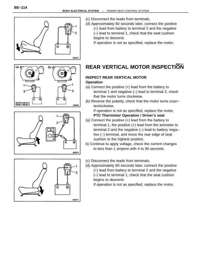
REAR VERTICAL MOTOR INSPECTION
INSPECT REAR VERTICAL MOTOROperation(a) Connect the positive (+) lead from the battery to
terminal 1 and negative (–) lead to terminal 2, checkthat the motor turns clockwise.
(b) Reverse the polarity, check that the motor turns coun–terclockwise.If operation is not as specified, replace the motor.PTC Thermistor Operation / Driver’s seat
(a) Connect the positive (+) lead from the battery toterminal 1, the positive (+) lead from the ammeter toterminal 2 and the negative (–) lead to battery nega–tive (–) terminal, and move the rear edge of seatcushion to the highest position.
b) Continue to apply voltage, check the current changesto less than 1 ampere with 4 to 90 seconds.
(c) Disconnect the leads from terminals.(d) Approximately 60 seconds later, connect the positive
(+) lead from battery to terminal 2 and the negative(–) lead to terminal 1, check that the seat cushionbegins to descend.If operation is not as specified, replace the motor.
(c) Disconnect the leads from terminals.(d) Approximately 60 seconds later, connect the positive
(+) lead from battery to terminal 2 and the negative(–) lead to terminal 1, check that the seat cushionbegins to descend.If operation is not as specified, replace the motor.
–BODY ELECTRICAL SYSTEM POWER SEAT CONTROL SYSTEMBE–114
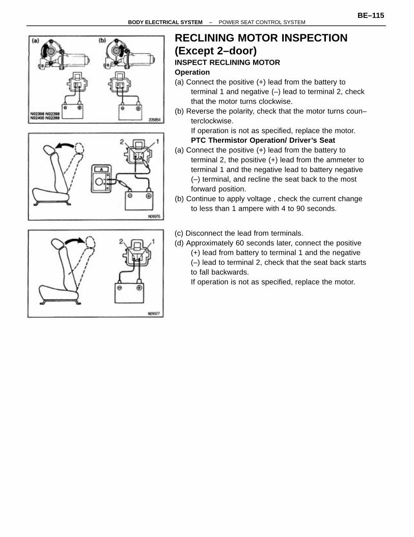
RECLINING MOTOR INSPECTION(Except 2–door)INSPECT RECLINING MOTOROperation(a) Connect the positive (+) lead from the battery to
terminal 1 and negative (–) lead to terminal 2, checkthat the motor turns clockwise.
(b) Reverse the polarity, check that the motor turns coun–terclockwise.If operation is not as specified, replace the motor.PTC Thermistor Operation/ Driver’s Seat
(a) Connect the positive (+) lead from the battery toterminal 2, the positive (+) lead from the ammeter toterminal 1 and the negative lead to battery negative(–) terminal, and recline the seat back to the mostforward position.
(b) Continue to apply voltage , check the current changeto less than 1 ampere with 4 to 90 seconds.
(c) Disconnect the lead from terminals.(d) Approximately 60 seconds later, connect the positive
(+) lead from battery to terminal 1 and the negative(–) lead to terminal 2, check that the seat back startsto fall backwards.If operation is not as specified, replace the motor.
–BODY ELECTRICAL SYSTEM POWER SEAT CONTROL SYSTEMBE–115
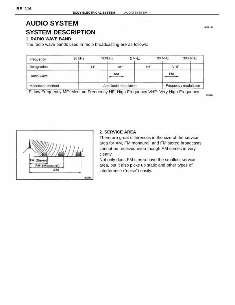
2. SERVICE AREAThere are great differences in the size of the servicearea for AM, FM monaural, and FM stereo broadcastscannot be received even though AM comes in veryclearly.Not only does FM stereo have the smallest servicearea, but it also picks up static and other types ofinterference (”noise”) easily.
AUDIO SYSTEMSYSTEM DESCRIPTION1. RADIO WAVE BANDThe radio wave bands used in radio broadcasting are as follows:
LF: low Frequency MF: Medium Frequency HF: High Frequency VHF: Very High Frequency
Frequency modulationAmplitude modulationModulation method
Designation
Radio wave
Frequency 300 MHz30 MHz300kHz30 kHz 3 MHz
VHF
–BODY ELECTRICAL SYSTEM AUDIO SYSTEMBE–116
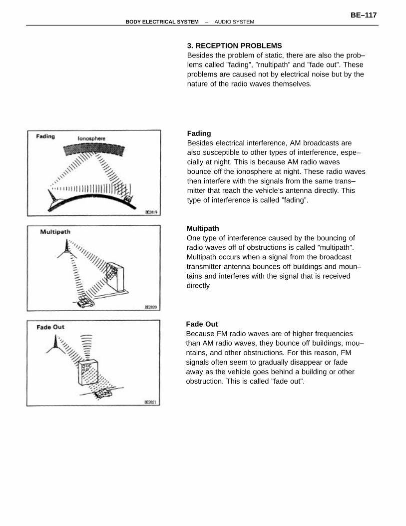
FadingBesides electrical interference, AM broadcasts arealso susceptible to other types of interference, espe–cially at night. This is because AM radio wavesbounce off the ionosphere at night. These radio wavesthen interfere with the signals from the same trans–mitter that reach the vehicle’s antenna directly. Thistype of interference is called ”fading”.
MultipathOne type of interference caused by the bouncing ofradio waves off of obstructions is called ”multipath”.Multipath occurs when a signal from the broadcasttransmitter antenna bounces off buildings and moun–tains and interferes with the signal that is receiveddirectly
Fade OutBecause FM radio waves are of higher frequenciesthan AM radio waves, they bounce off buildings, mou–ntains, and other obstructions. For this reason, FMsignals often seem to gradually disappear or fadeaway as the vehicle goes behind a building or otherobstruction. This is called ”fade out”.
3. RECEPTION PROBLEMSBesides the problem of static, there are also the prob–lems called ”fading”, ”rnultipath” and ”fade out”. Theseproblems are caused not by electrical noise but by thenature of the radio waves themselves.
–BODY ELECTRICAL SYSTEM AUDIO SYSTEMBE–117
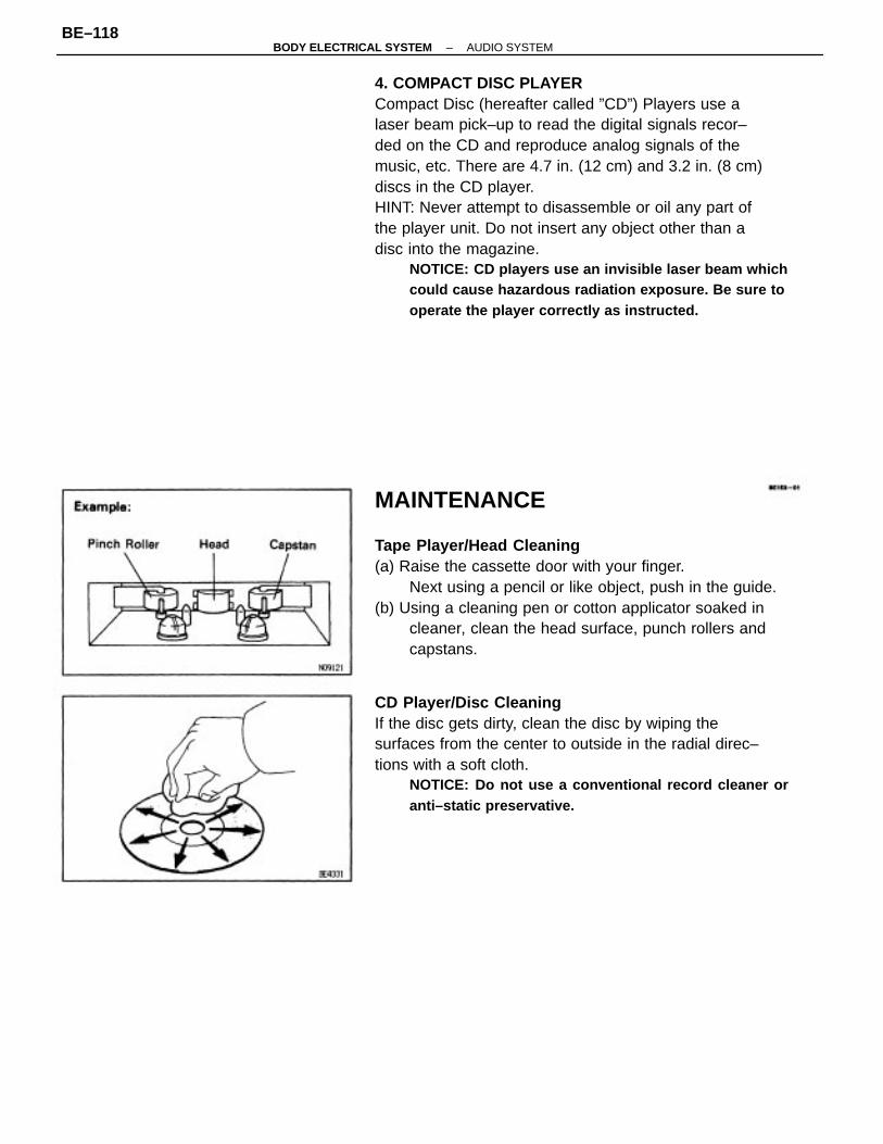
4. COMPACT DISC PLAYERCompact Disc (hereafter called ”CD”) Players use alaser beam pick–up to read the digital signals recor–ded on the CD and reproduce analog signals of themusic, etc. There are 4.7 in. (12 cm) and 3.2 in. (8 cm)discs in the CD player.HINT: Never attempt to disassemble or oil any part ofthe player unit. Do not insert any object other than adisc into the magazine.
NOTICE: CD players use an invisible laser beam whichcould cause hazardous radiation exposure. Be sure tooperate the player correctly as instructed.
MAINTENANCE
Tape Player/Head Cleaning(a) Raise the cassette door with your finger.
Next using a pencil or like object, push in the guide.(b) Using a cleaning pen or cotton applicator soaked in
cleaner, clean the head surface, punch rollers andcapstans.
CD Player/Disc CleaningIf the disc gets dirty, clean the disc by wiping thesurfaces from the center to outside in the radial direc–tions with a soft cloth.
NOTICE: Do not use a conventional record cleaner oranti–static preservative.
–BODY ELECTRICAL SYSTEM AUDIO SYSTEMBE–118
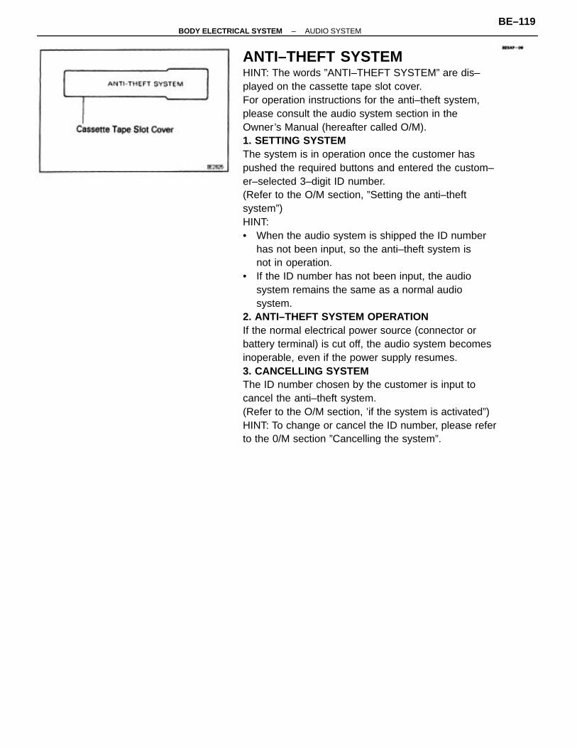
ANTI–THEFT SYSTEMHINT: The words ”ANTI–THEFT SYSTEM” are dis–played on the cassette tape slot cover.For operation instructions for the anti–theft system,please consult the audio system section in theOwner’s Manual (hereafter called O/M).1. SETTING SYSTEMThe system is in operation once the customer haspushed the required buttons and entered the custom–er–selected 3–digit ID number.(Refer to the O/M section, ”Setting the anti–theftsystem”)HINT:• When the audio system is shipped the ID number
has not been input, so the anti–theft system isnot in operation.
• If the ID number has not been input, the audiosystem remains the same as a normal audiosystem.
2. ANTI–THEFT SYSTEM OPERATIONIf the normal electrical power source (connector orbattery terminal) is cut off, the audio system becomesinoperable, even if the power supply resumes.3. CANCELLING SYSTEMThe ID number chosen by the customer is input tocancel the anti–theft system.(Refer to the O/M section, ’if the system is activated”)HINT: To change or cancel the ID number, please referto the 0/M section ”Cancelling the system”.
–BODY ELECTRICAL SYSTEM AUDIO SYSTEMBE–119
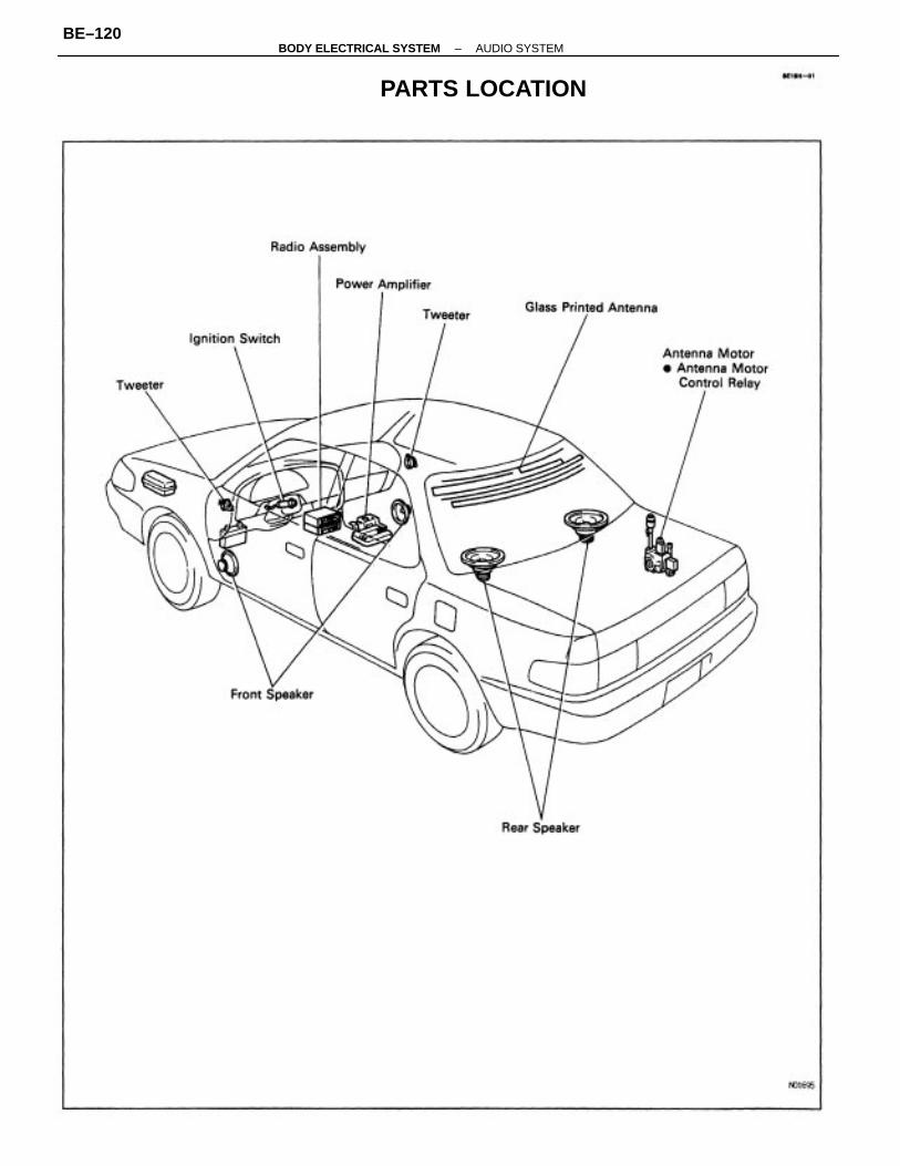
PARTS LOCATION
–BODY ELECTRICAL SYSTEM AUDIO SYSTEMBE–120
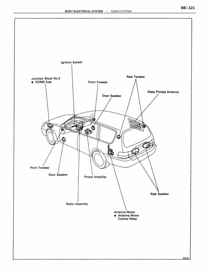
–BODY ELECTRICAL SYSTEM AUDIO SYSTEMBE–121
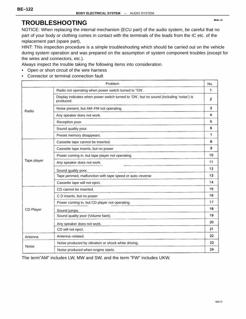
TROUBLESHOOTINGNOTICE: When replacing the internal mechanism (ECU part) of the audio system, be careful that nopart of your body or clothing comes in contact with the terminals of the leads from the IC etc. of thereplacement part (spare part),HINT: This inspection procedure is a simple troubleshooting which should be carried out on the vehicleduring system operation and was prepared on the assumption of system component troubles (except forthe wires and connectors, etc.).Always inspect the trouble taking the following items into consideration.• Open or short circuit of the wire harness• Connector or terminal connection fault
Display indicates when power switch turned to ’ON’, but no sound (including ’noise’) isproduced.
The term”AM” includes LW, MW and SW, and the term ”FW” includes UKW.
Power coming in, but CD player not operating.
Sound jumps.
Any speaker does not work.
Sound quality poor.
Sound quality poor (Volume faint).
Any speaker does not work.
Tape jammed, malfunction with tape speed or auto–reverse
Radio not operating when power switch turned to ”ON’.
Noise produced by vibration or shock white driving.
Power coming in, but tape player not operating.
Noise present, but AM–FM not operating.
Noise produced when engine starts.
Cassette tape inserts, but no power
Cassette tape cannot be inserted.
Any speaker does not work.
Cassette tape will not eject.
Preset memory disappears.
C D inserts, but no power
CD cannot be inserted.
Sound quality poor.
CD will not eject.
Reception poor.
Antenna–related.
Tape player
CD Player
Problem
Antenna
Radio
Noise
No.
–BODY ELECTRICAL SYSTEM AUDIO SYSTEMBE–122
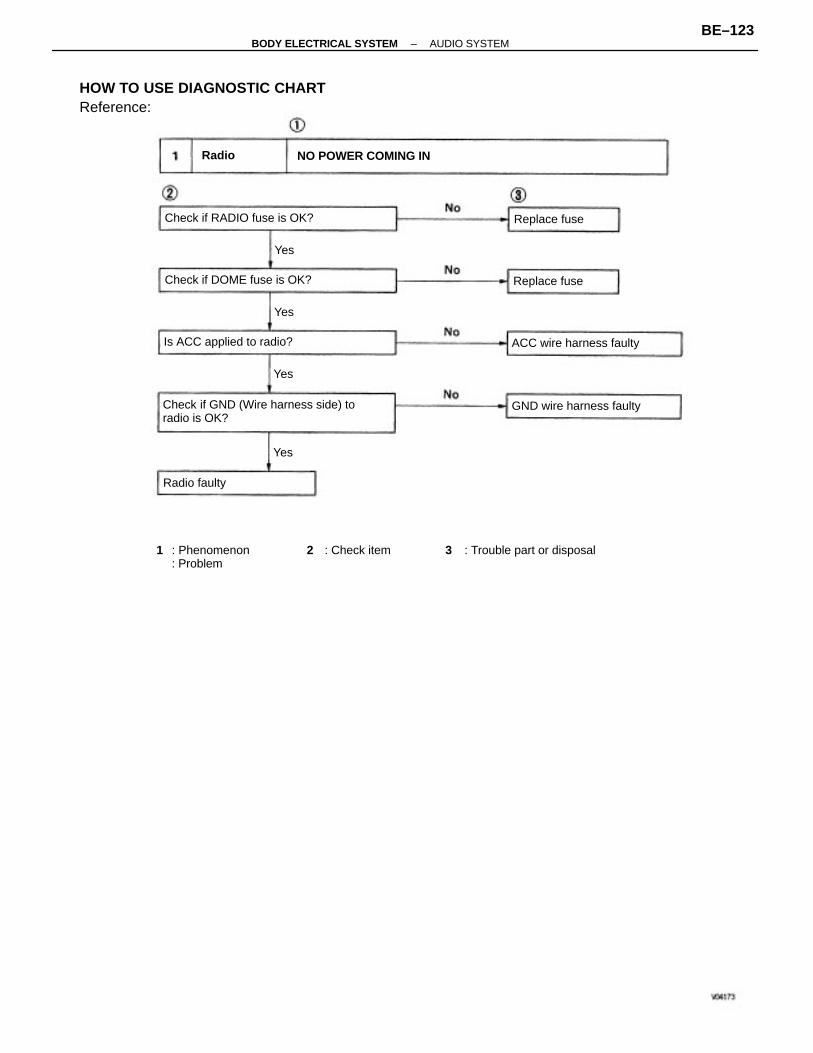
HOW TO USE DIAGNOSTIC CHARTReference:
Check if GND (Wire harness side) toradio is OK?
3 : Trouble part or disposal1 : Phenomenon: Problem
Check if RADIO fuse is OK?
Check if DOME fuse is OK?
NO POWER COMING IN
GND wire harness faulty
Is ACC applied to radio? ACC wire harness faulty
2 : Check item
Replace fuse
Replace fuse
Radio faulty
Radio
Yes
Yes
Yes
Yes
–BODY ELECTRICAL SYSTEM AUDIO SYSTEMBE–123
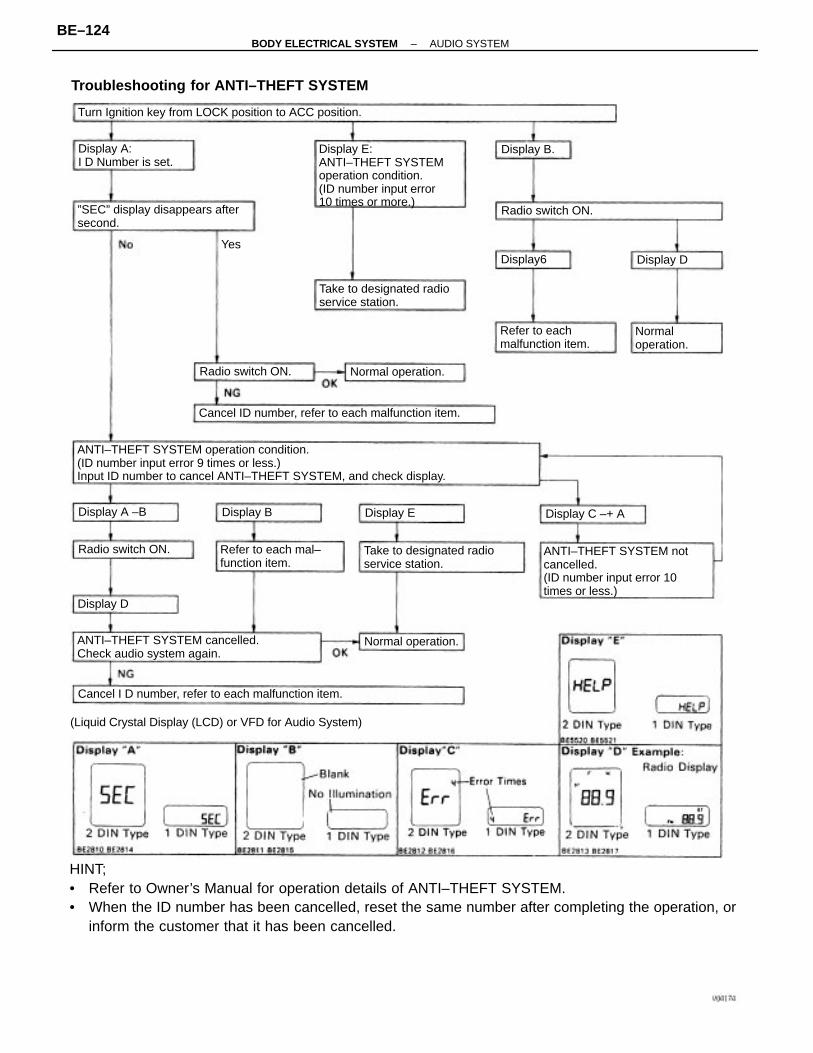
HINT;• Refer to Owner’s Manual for operation details of ANTI–THEFT SYSTEM.• When the ID number has been cancelled, reset the same number after completing the operation, or
inform the customer that it has been cancelled.
ANTI–THEFT SYSTEM operation condition.(ID number input error 9 times or less.)Input ID number to cancel ANTI–THEFT SYSTEM, and check display.
Troubleshooting for ANTI–THEFT SYSTEM
(Liquid Crystal Display (LCD) or VFD for Audio System)
Display E:ANTI–THEFT SYSTEMoperation condition.(ID number input error10 times or more.)
ANTI–THEFT SYSTEM notcancelled.(ID number input error 10times or less.)
Turn Ignition key from LOCK position to ACC position.
ANTI–THEFT SYSTEM cancelled.Check audio system again.
Cancel ID number, refer to each malfunction item.
Cancel I D number, refer to each malfunction item.
”SEC” display disappears aftersecond.
Take to designated radioservice station.
Take to designated radioservice station.
Refer to each mal–function item.
Refer to eachmalfunction item.
Display A:I D Number is set.
Normal operation.
Normal operation.
Normaloperation.
Radio switch ON.
Radio switch ON.
Radio switch ON.
Display C –+ ADisplay A –B
Display B.
Display D
Display D
Display B
Display6
Display E
Yes
–BODY ELECTRICAL SYSTEM AUDIO SYSTEMBE–124
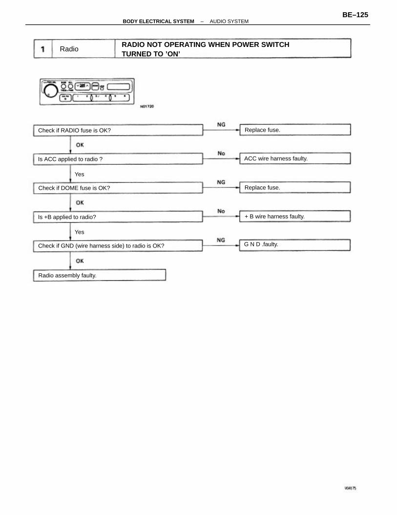
RADIO NOT OPERATING WHEN POWER SWITCHTURNED TO ’ON’
Check if GND (wire harness side) to radio is OK?
Check if RADIO fuse is OK?
Check if DOME fuse is OK?
Is ACC applied to radio ? ACC wire harness faulty.
Is +B applied to radio? + B wire harness faulty.
Radio assembly faulty.
Replace fuse.
G N D .faulty.
Replace fuse.
Radio
Yes
Yes
–BODY ELECTRICAL SYSTEM AUDIO SYSTEMBE–125
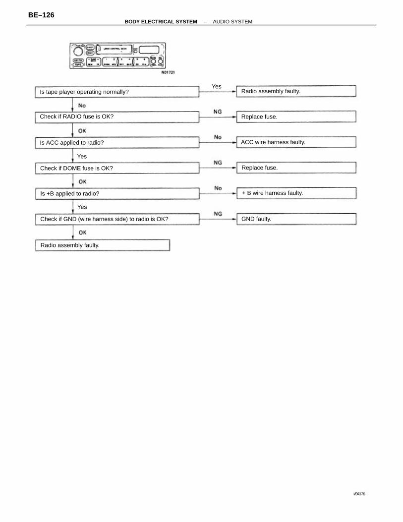
Check if GND (wire harness side) to radio is OK?
Is tape player operating normally?
Check if RADIO fuse is OK?
Check if DOME fuse is OK?
Is ACC applied to radio? ACC wire harness faulty.
Is +B applied to radio? + B wire harness faulty.
Radio assembly faulty.
Radio assembly faulty.
Replace fuse.
Replace fuse.
GND faulty.
Yes
Yes
Yes
–BODY ELECTRICAL SYSTEM AUDIO SYSTEMBE–126
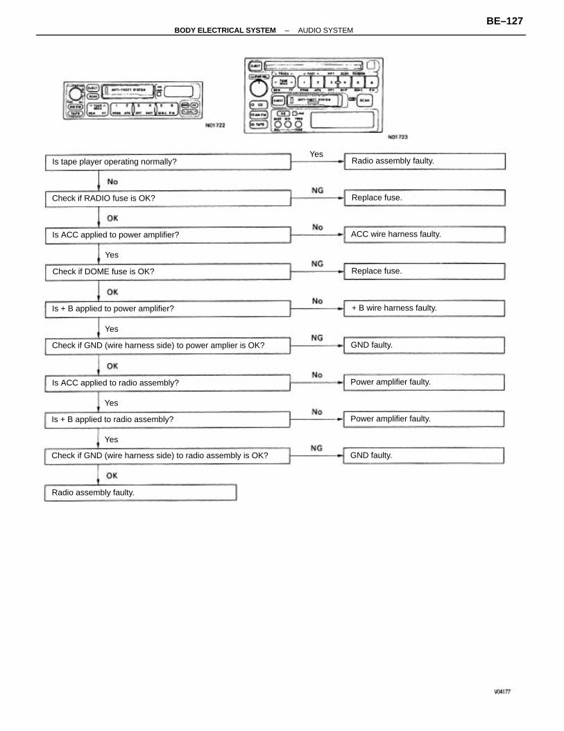
Check if GND (wire harness side) to radio assembly is OK?
Check if GND (wire harness side) to power amplier is OK?
Is ACC applied to power amplifier?
Is tape player operating normally?
Is + B applied to power amplifier?
Is ACC applied to radio assembly?
Is + B applied to radio assembly?
Check if RADIO fuse is OK?
Check if DOME fuse is OK?
ACC wire harness faulty.
+ B wire harness faulty.
Power amplifier faulty.
Power amplifier faulty.
Radio assembly faulty.
Radio assembly faulty.
Replace fuse.
Replace fuse.
GND faulty.
GND faulty.
Yes
Yes
Yes
Yes
Yes
–BODY ELECTRICAL SYSTEM AUDIO SYSTEMBE–127
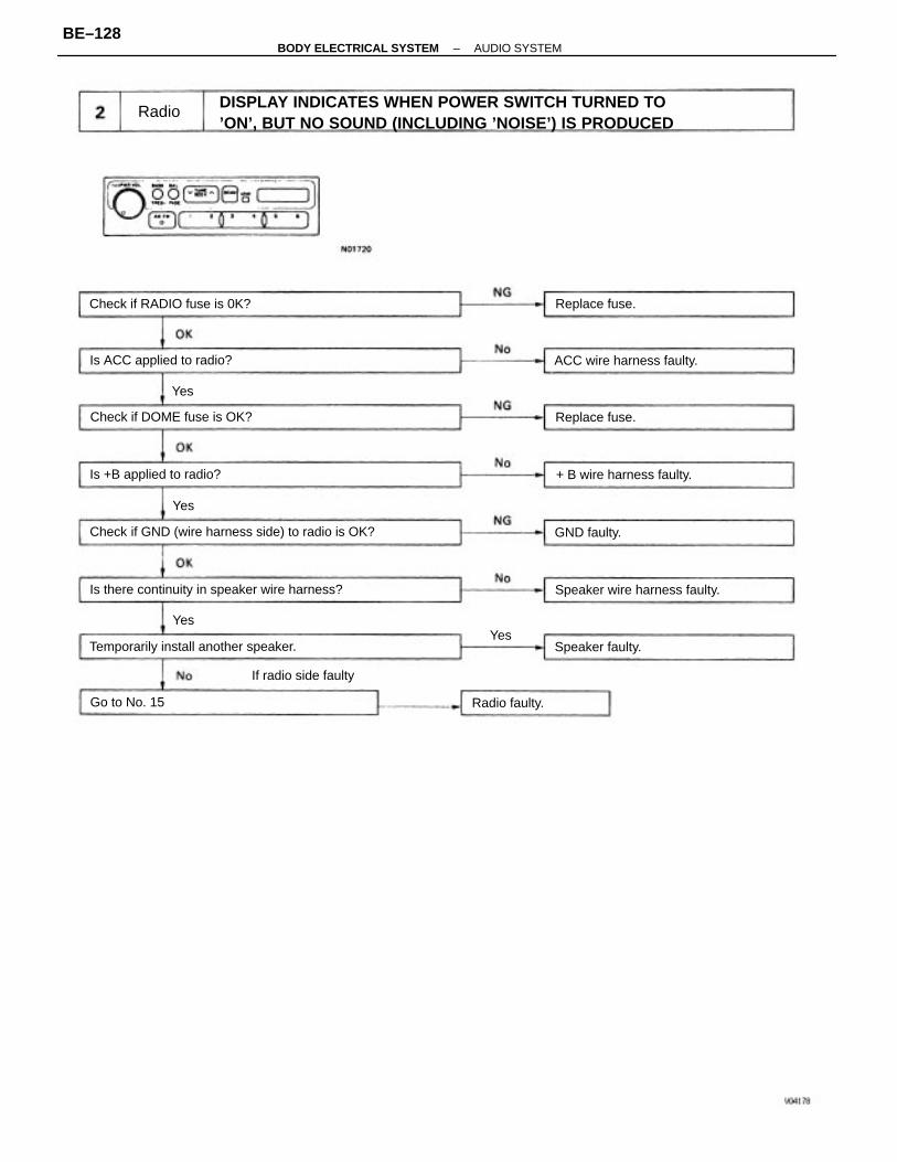
DISPLAY INDICATES WHEN POWER SWITCH TURNED TO’ON’, BUT NO SOUND (INCLUDING ’NOISE’) IS PRODUCED
Check if GND (wire harness side) to radio is OK?
Is there continuity in speaker wire harness?
Temporarily install another speaker.
Speaker wire harness faulty.
Check if RADIO fuse is 0K?
Check if DOME fuse is OK?
Is ACC applied to radio? ACC wire harness faulty.
Is +B applied to radio? + B wire harness faulty.
If radio side faulty
Speaker faulty.
Replace fuse.
Replace fuse.
Radio faulty.Go to No. 15
GND faulty.
Radio
Yes
YesYes
Yes
–BODY ELECTRICAL SYSTEM AUDIO SYSTEMBE–128
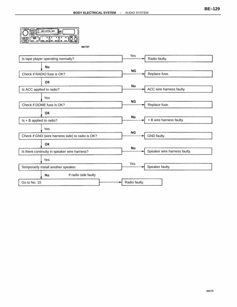
Check if GND (wire harness side) to radio is OK?
Is there continuity in speaker wire harness?
Temporarily install another speaker.
Is tape player operating normally?
Speaker wire harness faulty.
Check if RADIO fuse is OK?
Check if DOME fuse is OK?
Is ACC applied to radio? ACC wire harness faulty.
+ B wire harness faulty.Is + B applied to radio?
If radio side faulty
Speaker faulty.
Replace fuse.
Replace fuse.
Radio faulty.
Radio faulty.
Go to No. 15
GND faulty.
Yes
YesYes
Yes
Yes
–BODY ELECTRICAL SYSTEM AUDIO SYSTEMBE–129
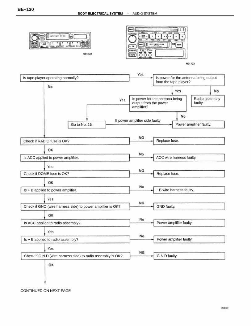
Is power for the antenna beingoutput from the poweramplifier?
Check if GNO (wire harness side) to power amplifier is OK?
Is power for the antenna being outputfrom the tape player?
Check if G N D (wire harness side) to radio assembly is OK?
Is ACC applied to power amplifier.
Is ACC applied to radio assembly?
Is tape player operating normally?
Is + B applied to power amplifier.
Is + B applied to radio assembly?
If power amplifier side faulty
CONTINUED ON NEXT PAGE
Check if DOME fuse is OK?
Radio assemblyfaulty.
Check if RADIO fuse is OK?
ACC wire harness faulty.
+B wire harness faulty.
Power amplifier faulty.
Power amplifier faulty.
Power amplifier faulty.
Replace fuse.
Replace fuse.
Go to No. 15
GND faulty.
G N D faulty.
Yes
Yes
Yes
Yes
Yes
Yes
Yes
–BODY ELECTRICAL SYSTEM AUDIO SYSTEMBE–130
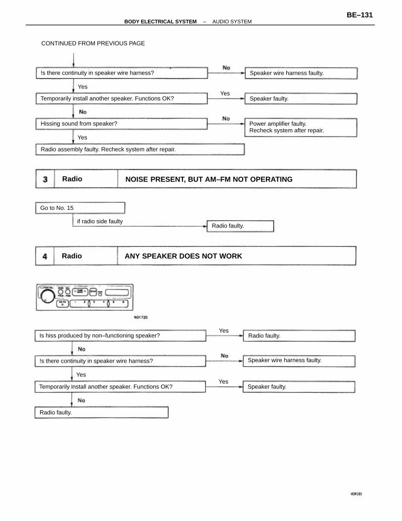
NOISE PRESENT, BUT AM–FM NOT OPERATING
ANY SPEAKER DOES NOT WORK
Temporarily install another speaker. Functions OK?
Radio assembly faulty. Recheck system after repair.
Temporarily install another speaker. Functions OK?
Is hiss produced by non–functioning speaker?
Power amplifier faulty.Recheck system after repair.
!s there continuity in speaker wire harness?
!s there continuity in speaker wire harness?
CONTINUED FROM PREVIOUS PAGE
Speaker wire harness faulty.
Hissing sound from speaker?
Speaker wire harness faulty.
if radio side faulty
Speaker faulty.
Speaker faulty.
Radio faulty.
Radio faulty.
Radio faulty.
Go to No. 15
Radio
Radio
Yes
Yes
Yes
Yes
Yes
Yes
–BODY ELECTRICAL SYSTEM AUDIO SYSTEMBE–131
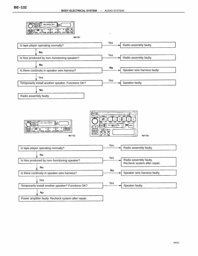
Temporarily install another speaker? Functions OK?
Temporarily install another speaker. Functions OK?
Power amplifier faulty. Recheck system after repair.
Is hiss produced by non–functioning speaker?
Is hiss produced by non–functioning speaker?
Radio assembly faulty.Recheck system after repair.
Is there continuity in speaker wire harness?
Is there continuity in speaker wire harness?
Is tape player operating normally?
Is tape player operating normally?
Speaker wire harness faulty.
Speaker wire harness faulty.
Radio assembly faulty.
Radio assembly faulty.
Radio assembly faulty.
Radio assembly faulty.
Speaker faulty.
Speaker faulty.Yes
Yes
Yes
Yes
YesYes
Yes
Yes
–BODY ELECTRICAL SYSTEM AUDIO SYSTEMBE–132
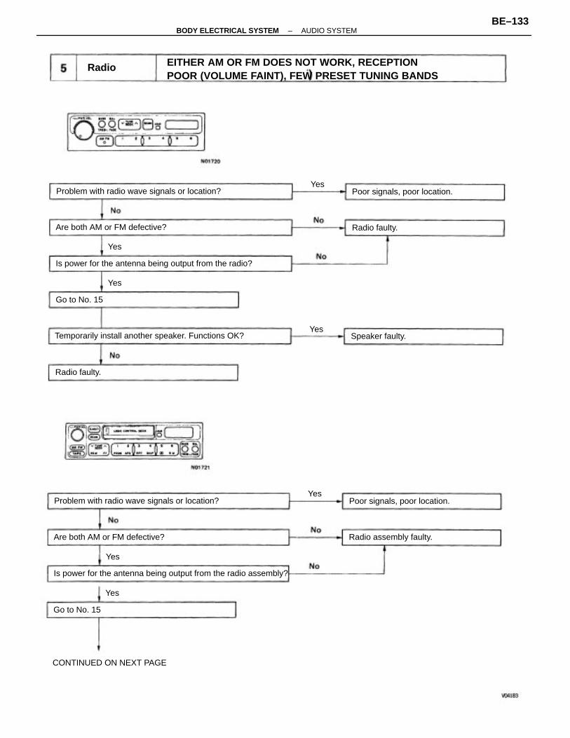
EITHER AM OR FM DOES NOT WORK, RECEPTIONPOOR (VOLUME FAINT), FEW PRESET TUNING BANDS
Is power for the antenna being output from the radio assembly?
Is power for the antenna being output from the radio?
Temporarily install another speaker. Functions OK?
Problem with radio wave signals or location?
Problem with radio wave signals or location?
Are both AM or FM defective?
Are both AM or FM defective?
Poor signals, poor location.
CONTINUED ON NEXT PAGE
Poor signals, poor location.
Radio assembly faulty.
Speaker faulty.
Radio faulty.
Radio faulty.
Go to No. 15
Go to No. 15
Radio
Yes
Yes
Yes
Yes
Yes
Yes
Yes
–BODY ELECTRICAL SYSTEM AUDIO SYSTEMBE–133
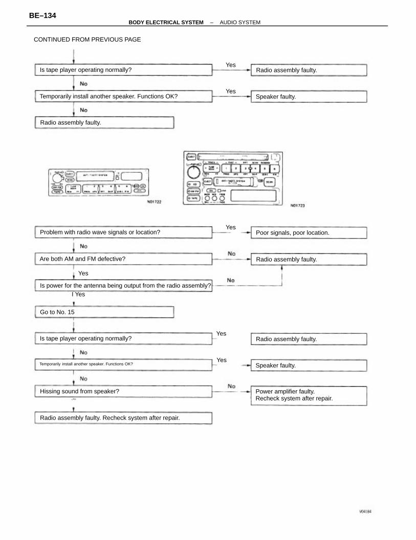
Is power for the antenna being output from the radio assembly?
Radio assembly faulty. Recheck system after repair.
Temporarily install another speaker. Functions OK?
Temporarily install another speaker. Functions OK?
Problem with radio wave signals or location?
Power amplifier faulty.Recheck system after repair.
CONTINUED FROM PREVIOUS PAGE
Is tape player operating normally?
Is tape player operating normally?
Are both AM and FM defective?
Hissing sound from speaker?
Poor signals, poor location.
Radio assembly faulty.
Radio assembly faulty.
Radio assembly faulty.
Radio assembly faulty.
Yes
Speaker faulty.
Speaker faulty.Yes
Go to No. 15
I Yes
¿Yes
Yes
Yes
Yes
Yes
–BODY ELECTRICAL SYSTEM AUDIO SYSTEMBE–134
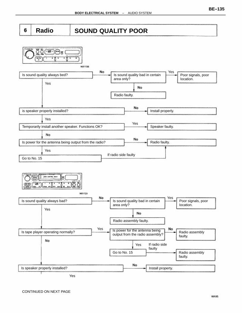
Yes
CONTINUED ON NEXT PAGE
Is power for the antenna beingoutput from the radio assembly?
Is power for the antenna being output from the radio?
Temporarily install another speaker. Functions OK?
Is sound quality bad in certainarea only?
Is sound quality bad in certainarea only?
SOUND QUALITY POOR
Is tape player operating normally?
is speaker properly installed?
Is sound quality always bed?
Is sound quality always bad?
Is speaker properly installed?
Poor signals, poorlocation.
Poor signals, poorlocation.
Radio assemblyfaulty.
Radio assemblyfaulty.
Radio assembly faulty.
If radio sidefaulty
If radio side faulty
Install property.
Install properly.
Speaker faulty.
Radio faulty.
Radio faulty.
Go to No. 15
Go to No. 15
Radio
Yes
Yes
Yes
Yes
Yes
Yes
Yes
Yes
Yes
–BODY ELECTRICAL SYSTEM AUDIO SYSTEMBE–135

Radio assembly or power amplifier faulty.Recheck system after repair.
Is power for the antennabeing output from thepower amplifier?
Is power for the antennabeing output from theradio assembly?
Temporarily install another speaker. Functions OK?
Temporarily install another speaker. Functions OK?
Radio assembly or poweramplifier faulty.
Is sound quality bad incertain areas only?
CONTINUED FROM PREVIOUS PAGE
Is tape player operating normally?
Is tape player operating normally?
Poor signals, poorlocation.
Is sound quality always bad?
Is speaker properly installed?
Power amplifier faulty.
Radio assembly faulty.
Radio assembly faulty.
Radio assembly faulty.
Install properly.
Speaker faulty.
Speaker faulty.
Yes
Yes
Yes
Yes
Yes
Yes
Yes
Yes
–BODY ELECTRICAL SYSTEM AUDIO SYSTEMBE–136
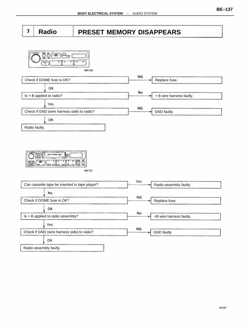
PRESET MEMORY DISAPPEARS
Can cassette tape be inserted in tape player?
Check if GND (wire harness side) to radio?
Check if GND (wire harness side) to radio?
Is + B applied to radio assembly?
Check if DOME fuse is OK?
Check if DOME fuse is OK?
Is + B applied to radio?
+B wire harness faulty.
+ B wire harness faulty.
Radio assembly faulty.
Radio assembly faulty.
Replace fuse.
Replace fuse.
Radio faulty.
GND faulty.
GND faulty.
Radio
Yes
Yes
Yes
–BODY ELECTRICAL SYSTEM AUDIO SYSTEMBE–137
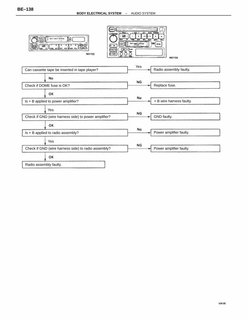
Check if GND (wire harness side) to power amplifier?
Check if GND (wire harness side) to radio assembly?
Can cassette tape be inserted in tape player?
Is + B applied to power amplifier?
Is + B applied to radio assembly?
Check if DOME fuse is OK?
+ B wire harness faulty.
Power amplifier faulty.
Power amplifier faulty.
Radio assembly faulty.
Radio assembly faulty.
Replace fuse.
GND faulty.
Yes
Yes
Yes
–BODY ELECTRICAL SYSTEM AUDIO SYSTEMBE–138
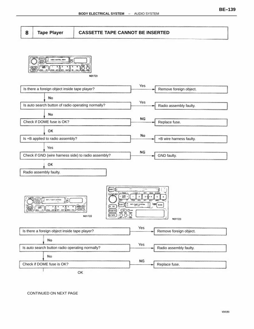
CASSETTE TAPE CANNOT BE INSERTED
OK
CONTINUED ON NEXT PAGE
Check if GND (wire harness side) to radio assembly?
Is auto search button of radio operating normally?
Is auto search button radio operating normally?
Is there a foreign object inside tape player?
Is there a foreign object inside tape player?
Is +B applied to radio assembly?
Check if DOME fuse is OK?
Check if DOME fuse is OK?
Remove foreign object.
+B wire harness faulty.
Remove foreign object.
Radio assembly faulty.
Radio assembly faulty.
Radio assembly faulty.
Tape Player
Replace fuse.
Replace fuse.
GND faulty.
Yes
Yes
Yes
Yes
Yes
–BODY ELECTRICAL SYSTEM AUDIO SYSTEMBE–139
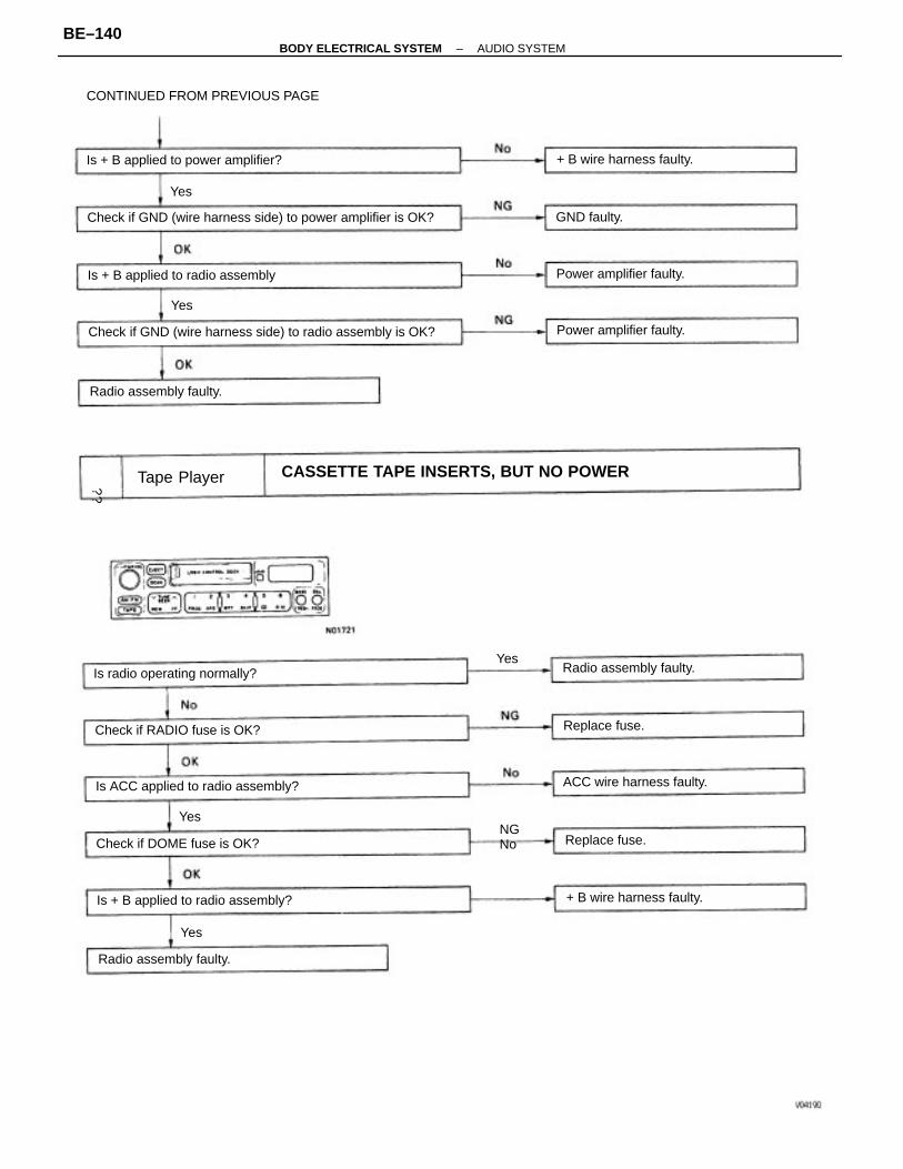
CASSETTE TAPE INSERTS, BUT NO POWER
Check if GND (wire harness side) to radio assembly is OK?
Check if GND (wire harness side) to power amplifier is OK?
CONTINUED FROM PREVIOUS PAGE
Is ACC applied to radio assembly?
Is + B applied to power amplifier?
Is + B applied to radio assembly?
Is + B applied to radio assembly
Is radio operating normally?
Check if RADIO fuse is OK?
Check if DOME fuse is OK?
ACC wire harness faulty.
+ B wire harness faulty.
+ B wire harness faulty.
Power amplifier faulty.
Power amplifier faulty.
Radio assembly faulty.
Radio assembly faulty.
Radio assembly faulty.
Tape Player
NGNo
Replace fuse.
Replace fuse.
GND faulty.
Yes
Yes
Yes
Yes
Yes
¿¿
–BODY ELECTRICAL SYSTEM AUDIO SYSTEMBE–140
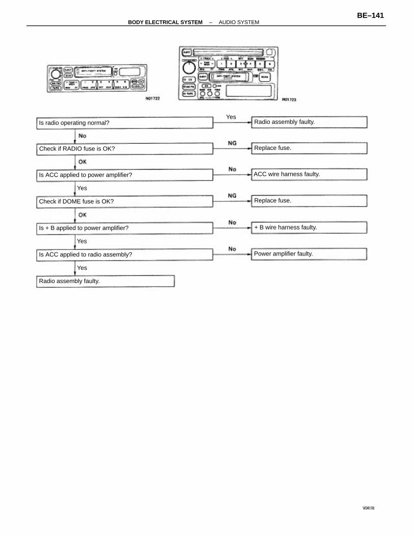
Is ACC applied to power amplifier?
Is ACC applied to radio assembly?
Is + B applied to power amplifier?
Check if DOME fuse is OK?
Check if RADIO fuse is OK?
Is radio operating normal?
ACC wire harness faulty.
+ B wire harness faulty.
Power amplifier faulty.
Radio assembly faulty.
Radio assembly faulty.
Replace fuse.
Replace fuse.
Yes
Yes
Yes
Yes
–BODY ELECTRICAL SYSTEM AUDIO SYSTEMBE–141
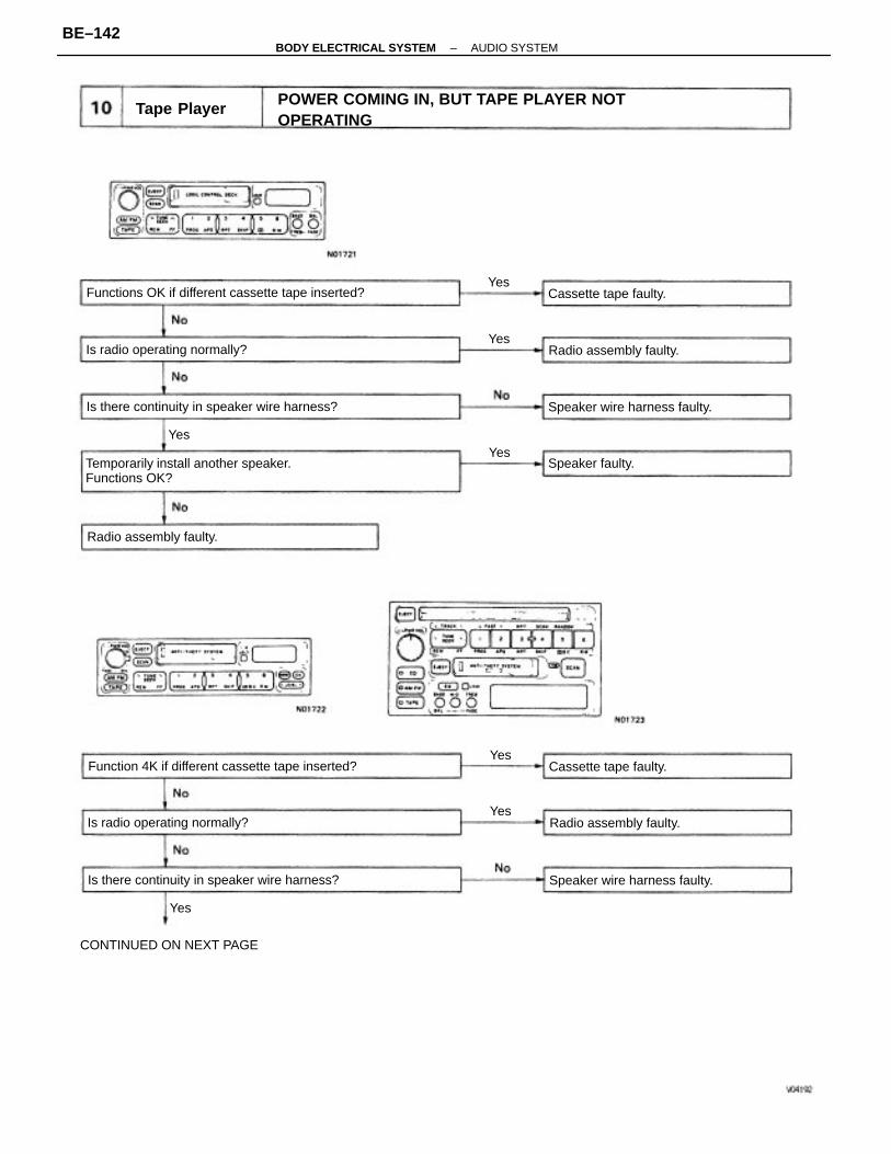
POWER COMING IN, BUT TAPE PLAYER NOTOPERATING
Temporarily install another speaker.Functions OK?
Functions OK if different cassette tape inserted?
Function 4K if different cassette tape inserted?
Is there continuity in speaker wire harness?
Is there continuity in speaker wire harness? Speaker wire harness faulty.
Is radio operating normally?
Is radio operating normally?
CONTINUED ON NEXT PAGE
Speaker wire harness faulty.
Radio assembly faulty.
Radio assembly faulty.
Radio assembly faulty.
Tape Player
Cassette tape faulty.
Cassette tape faulty.
Speaker faulty.
Yes
YesYes
Yes
Yes
Yes
Yes
–BODY ELECTRICAL SYSTEM AUDIO SYSTEMBE–142
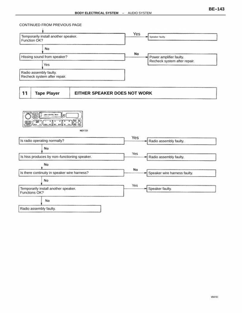
EITHER SPEAKER DOES NOT WORK
Temporarily install another speaker.Function OK?
Temporarily install another speaker.Functions OK?
Power amplifier faulty.Recheck system after repair.
Is hiss produces by non–functioning speaker.
Radio assembly faulty.Recheck system after repair.
Is there continuity in speaker wire harness?
CONTINUED FROM PREVIOUS PAGE
Hissing sound from speaker?
Is radio operating normally?
Speaker wire harness faulty.
Radio assembly faulty.
Radio assembly faulty.
Radio assembly faulty.
Tape Player
Speaker faulty.
Speaker faulty.
Yes
Yes
Yes
Yes
Yes
–BODY ELECTRICAL SYSTEM AUDIO SYSTEMBE–143
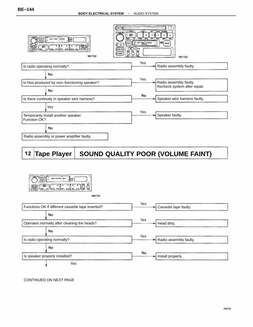
SOUND QUALITY POOR (VOLUME FAINT)
Yes
CONTINUED ON NEXT PAGE
Temporarily install another speaker.Function OK?
Functions OK if different cassette tape inserted?
Is hiss produced by non–functioning speaker? Radio assembly faulty.Recheck system after repair.
Is there continuity in speaker wire harness?
Operates normally after cleaning the heads?
Radio assembly or power amplifier faulty.
Is speaker properly installed?
Speaker wire harness faulty.
Is radio operating normally?
Is radio operating normally? Radio assembly faulty.
Radio assembly faulty.
Tape Player
Cassette tape faulty.
Install properly.
Speaker faulty.
Head dirty.
Yes
Yes
Yes
Yes
Yes
Yes
Yes
–BODY ELECTRICAL SYSTEM AUDIO SYSTEMBE–144
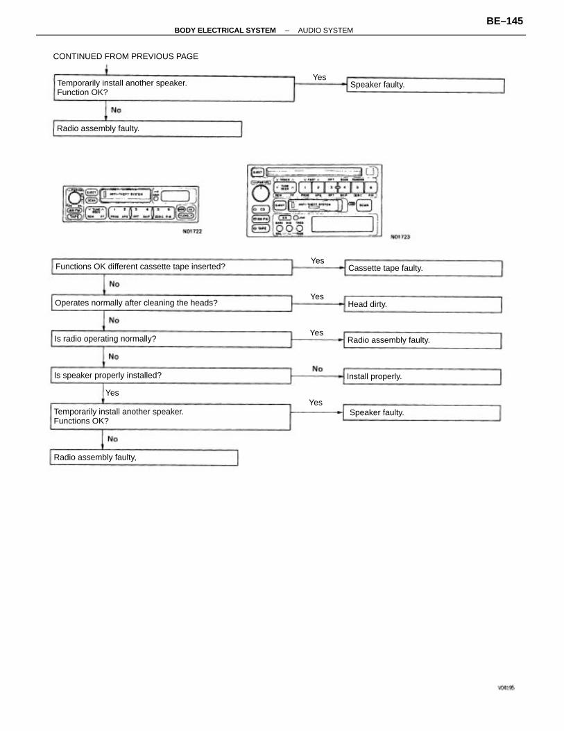
Temporarily install another speaker.Functions OK?
Temporarily install another speaker.Function OK?
Functions OK different cassette tape inserted?
Operates normally after cleaning the heads?
CONTINUED FROM PREVIOUS PAGE
Is radio operating normally?
Is speaker properly installed?
Radio assembly faulty.
Radio assembly faulty.
Radio assembly faulty,
Cassette tape faulty.
Install properly.
Speaker faulty.
Speaker faulty.
Head dirty.
Yes
Yes
Yes
Yes
Yes
Yes
–BODY ELECTRICAL SYSTEM AUDIO SYSTEMBE–145
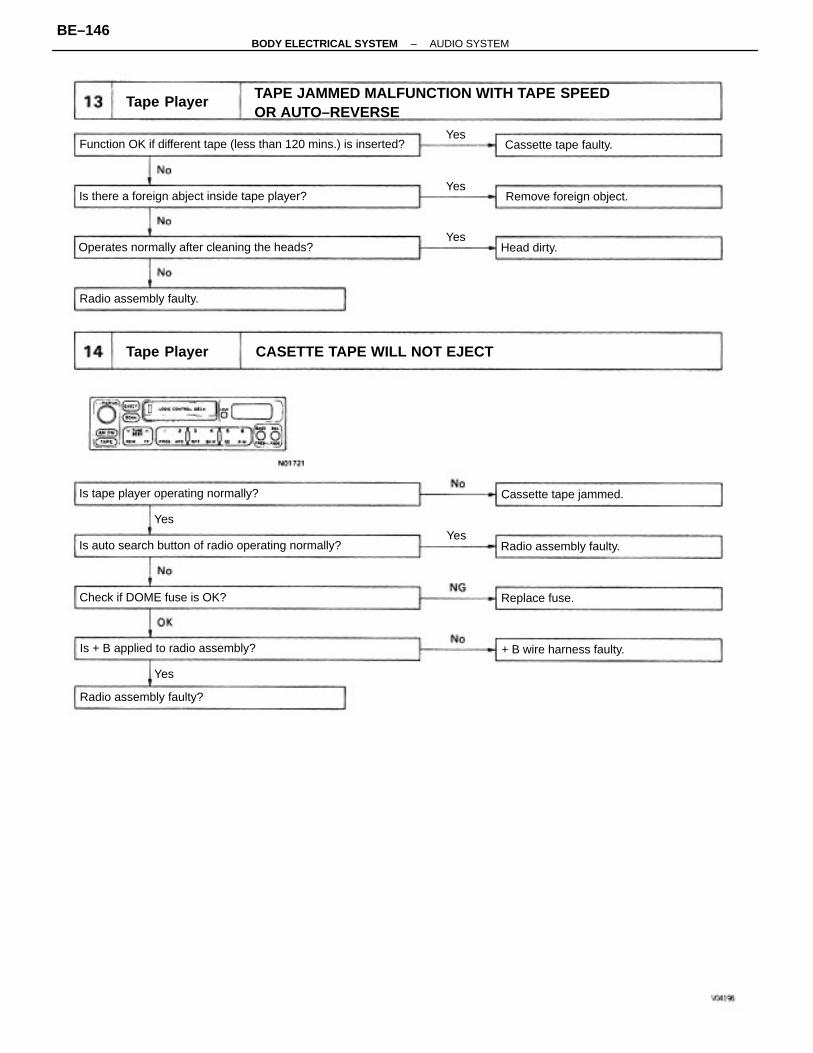
TAPE JAMMED MALFUNCTION WITH TAPE SPEEDOR AUTO–REVERSE
Function OK if different tape (less than 120 mins.) is inserted?
CASETTE TAPE WILL NOT EJECT
Is auto search button of radio operating normally?
Operates normally after cleaning the heads?
Is there a foreign abject inside tape player?
Is tape player operating normally?
Is + B applied to radio assembly?
Check if DOME fuse is OK?
+ B wire harness faulty.
Remove foreign object.
Cassette tape jammed.
Radio assembly faulty?
Radio assembly faulty.
Radio assembly faulty.
Tape Player
Tape Player
Cassette tape faulty.
Replace fuse.
Head dirty.
Yes
Yes
Yes
Yes
Yes
Yes
–BODY ELECTRICAL SYSTEM AUDIO SYSTEMBE–146
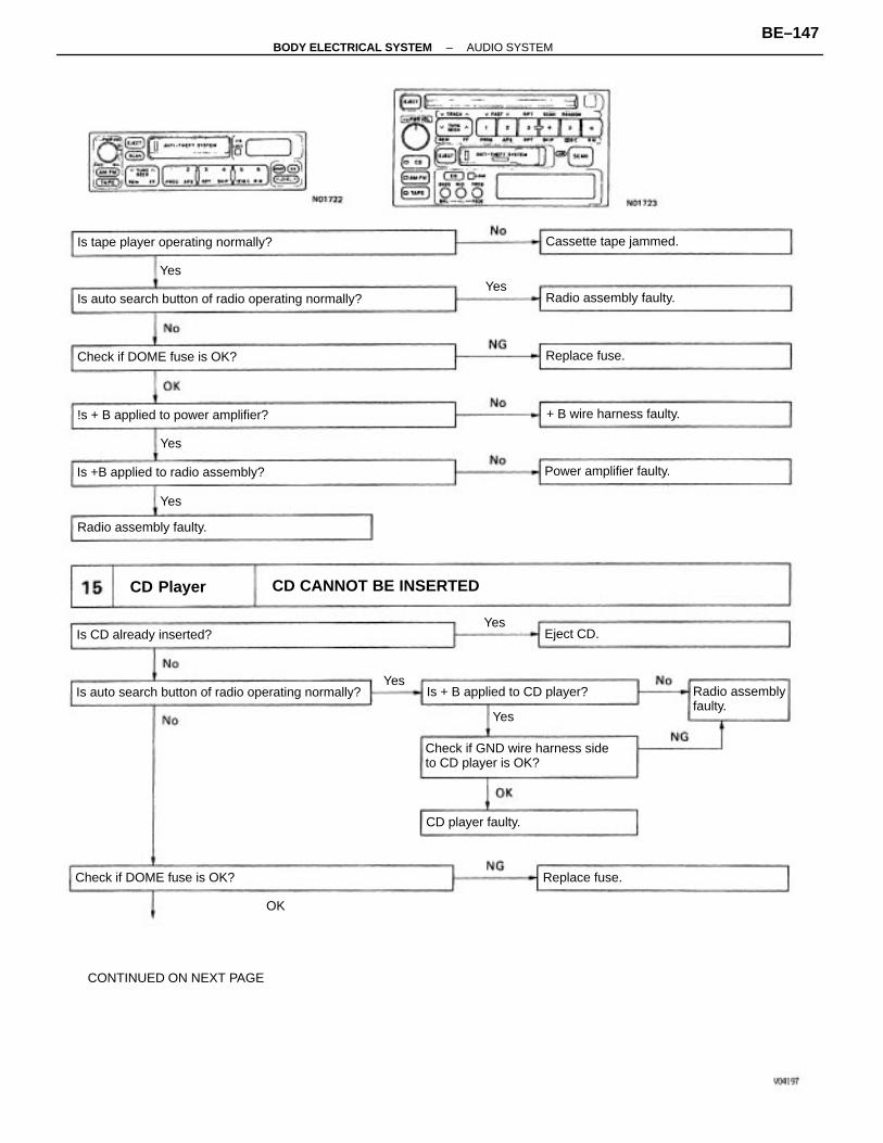
OK
CONTINUED ON NEXT PAGE
Check if GND wire harness sideto CD player is OK?
Is auto search button of radio operating normally?
Is auto search button of radio operating normally?
CD CANNOT BE INSERTED
Is tape player operating normally?
!s + B applied to power amplifier?
Is +B applied to radio assembly?
Is + B applied to CD player?
Check if DOME fuse is OK?
Radio assemblyfaulty.
Check if DOME fuse is OK?
+ B wire harness faulty.
Power amplifier faulty.
Is CD already inserted?
Cassette tape jammed.
Radio assembly faulty.
Radio assembly faulty.
CD Player
CD player faulty.
Replace fuse.
Replace fuse.
Eject CD.Yes
Yes
Yes
Yes
Yes
Yes
Yes
–BODY ELECTRICAL SYSTEM AUDIO SYSTEMBE–147
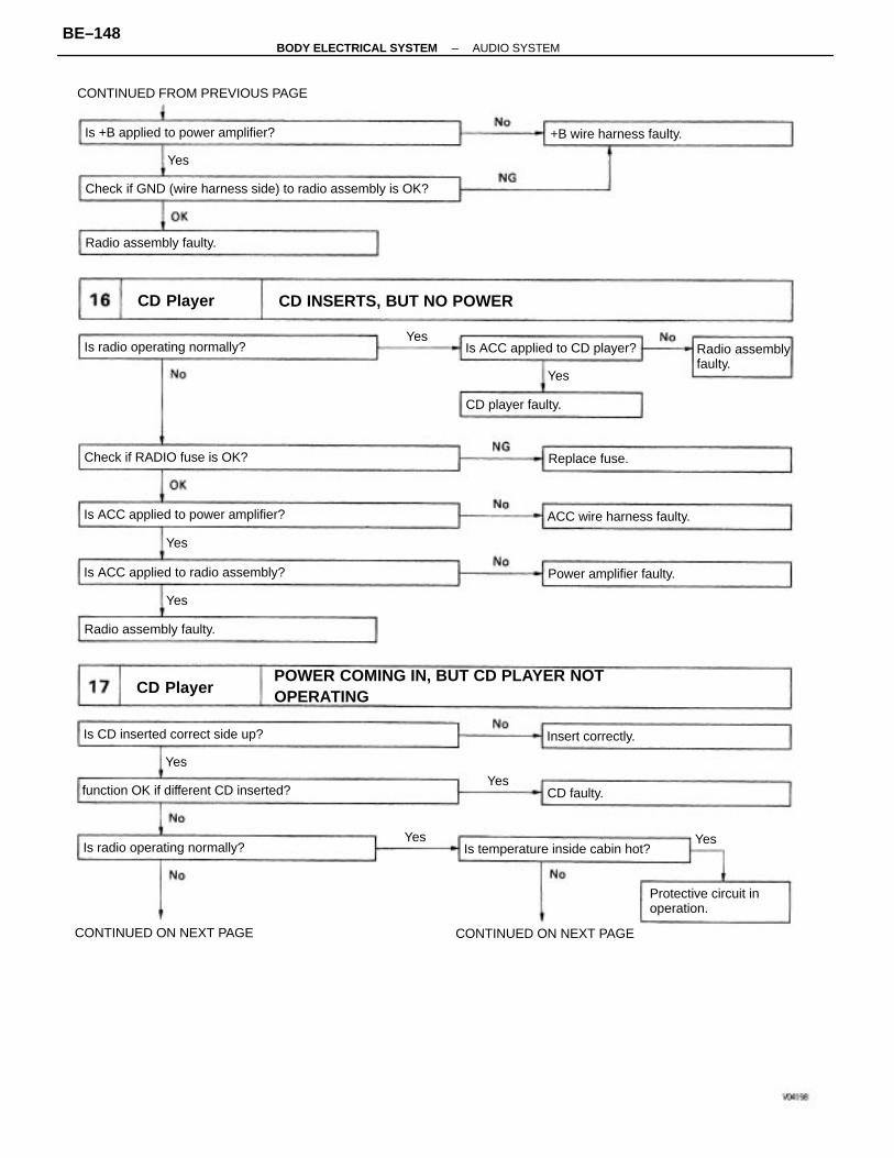
POWER COMING IN, BUT CD PLAYER NOTOPERATING
Check if GND (wire harness side) to radio assembly is OK?
CD INSERTS, BUT NO POWER
CONTINUED FROM PREVIOUS PAGE
Is ACC applied to power amplifier?
function OK if different CD inserted?
Is ACC applied to radio assembly?
Is +B applied to power amplifier?
Is temperature inside cabin hot?
Protective circuit inoperation.
Is CD inserted correct side up?
CONTINUED ON NEXT PAGE
Is ACC applied to CD player?Is radio operating normally?
CONTINUED ON NEXT PAGE
Is radio operating normally?
Check if RADIO fuse is OK?
Radio assemblyfaulty.
ACC wire harness faulty.
Power amplifier faulty.
+B wire harness faulty.
Radio assembly faulty.
Radio assembly faulty.
CD Player
CD Player
CD player faulty.
Insert correctly.
Replace fuse.
CD faulty.
Yes
Yes
Yes
Yes
Yes
Yes
Yes
Yes
Yes
–BODY ELECTRICAL SYSTEM AUDIO SYSTEMBE–148
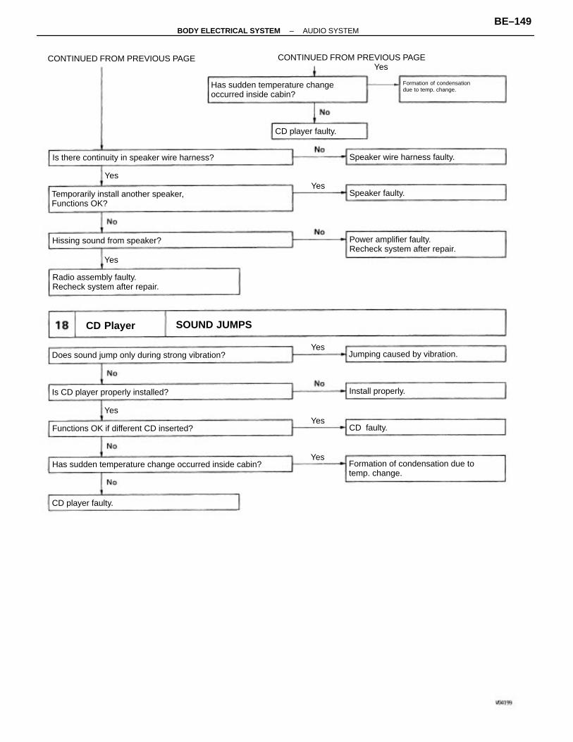
CONTINUED FROM PREVIOUS PAGEYes
Has sudden temperature change occurred inside cabin?
Temporarily install another speaker,Functions OK?
Formation of condensation due totemp. change.
Does sound jump only during strong vibration?
Has sudden temperature changeoccurred inside cabin?
Power amplifier faulty.Recheck system after repair.
Radio assembly faulty.Recheck system after repair.
Is there continuity in speaker wire harness?
Formation of condensationdue to temp. change.
CONTINUED FROM PREVIOUS PAGE
Functions OK if different CD inserted?
Is CD player properly installed?
Jumping caused by vibration.
Hissing sound from speaker?
Speaker wire harness faulty.
SOUND JUMPSCD Player
CD player faulty.
CD player faulty.
Install properly.
Speaker faulty.
CD faulty.
Yes
Yes
Yes
Yes
Yes
Yes
Yes
–BODY ELECTRICAL SYSTEM AUDIO SYSTEMBE–149
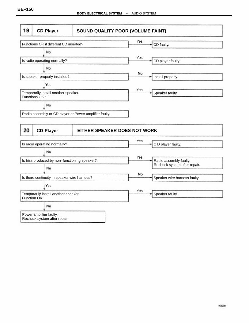
SOUND QUALITY POOR (VOLUME FAINT)
EITHER SPEAKER DOES NOT WORK
Radio assembly or CD player or Power amplifier faulty.
Temporarily install another speaker.Functions OK?
Temporarily install another speaker.Function OK.
Radio assembly faulty.Recheck system after repair.
Is hiss produced by non–functioning speaker?
Power amplifier faulty.Recheck system after repair.
Is there continuity in speaker wire harness?
Functions OK if different CD inserted?
Is speaker properly installed?
Is radio operating normally?
Speaker wire harness faulty.
Is radio operating normally?
CD Player
CD Player
C D player faulty.
CD player faulty.
Install properly.
Speaker faulty.
Speaker faulty.
CD faulty.Yes
Yes
Yes
Yes
Yes
Yes
Yes
Yes
–BODY ELECTRICAL SYSTEM AUDIO SYSTEMBE–150
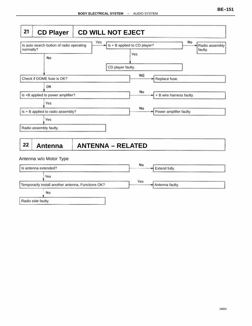
Is auto search button of radio operatingnormally?
Temporarily install another antenna, Functions OK?
ANTENNA – RELATED
CD WILL NOT EJECT
Is +B applied to power amplifier?
Antenna w/o Motor Type
Is + B applied to radio assembly?
Is + B applied to CD player? Radio assemblyfaulty.
Check if DOME fuse is OK?
+ B wire harness faulty.
Power amplifier faulty.
Radio assembly faulty.
Is antenna extended?
CD Player
Radio side faulty.
CD player faulty.
Antenna faulty.
Replace fuse.
Antenna
Extend fully.
Yes
Yes
Yes
Yes
Yes
Yes
–BODY ELECTRICAL SYSTEM AUDIO SYSTEMBE–151
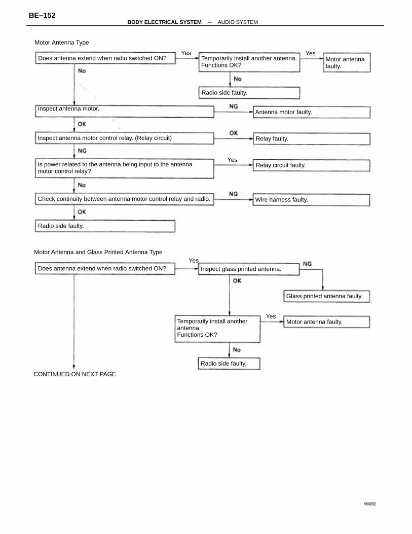
Motor Antenna and Glass Printed Antenna TypeYes
Is power related to the antenna being input to the antennamotor control relay?
Check continuity between antenna motor control relay and radio.
Temporarily install anotherantenna.Functions OK?
Temporarily install another antenna.Functions OK?
Inspect antenna motor control relay. (Relay circuit)
Does antenna extend when radio switched ON?
Does antenna extend when radio switched ON?
Inspect glass printed antenna.
Inspect antenna motor.
Glass printed antenna faulty.
CONTINUED ON NEXT PAGE
Motor Antenna Type
Motor antennafaulty.
Antenna motor faulty.
Motor antenna faulty.
Wire harness faulty.
Relay circuit faulty.
Radio side faulty.
Radio side faulty.
Radio side faulty.
Relay faulty.
Yes
Yes
Yes
Yes
–BODY ELECTRICAL SYSTEM AUDIO SYSTEMBE–152
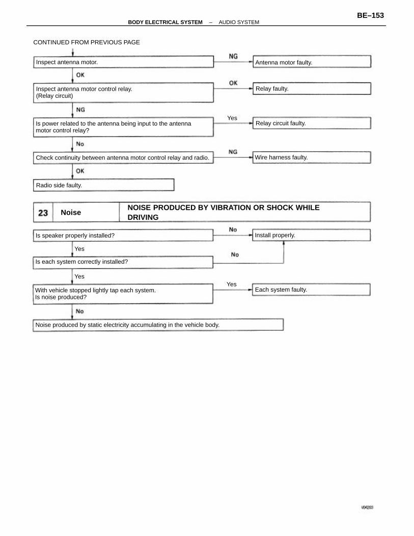
NOISE PRODUCED BY VIBRATION OR SHOCK WHILEDRIVING
Is power related to the antenna being input to the antennamotor control relay?
With vehicle stopped lightly tap each system.Is noise produced?
Noise produced by static electricity accumulating in the vehicle body.
CONTINUED FROM PREVIOUS PAGE
Check continuity between antenna motor control relay and radio.
Inspect antenna motor control relay.(Relay circuit)
Is each system correctly installed?
Is speaker properly installed?
Inspect antenna motor. Antenna motor faulty.
Wire harness faulty.
Each system faulty.
Relay circuit faulty.
Radio side faulty.
Install properly.
Relay faulty.
Noise
YesYes
Yes
Yes
–BODY ELECTRICAL SYSTEM AUDIO SYSTEMBE–153
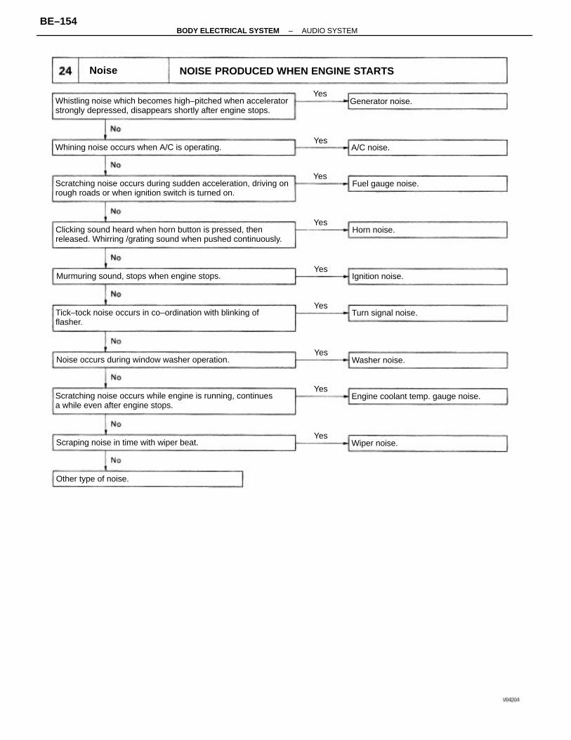
Whistling noise which becomes high–pitched when acceleratorstrongly depressed, disappears shortly after engine stops.
Scratching noise occurs during sudden acceleration, driving onrough roads or when ignition switch is turned on.
Clicking sound heard when horn button is pressed, thenreleased. Whirring /grating sound when pushed continuously.
Scratching noise occurs while engine is running, continuesa while even after engine stops.
Tick–tock noise occurs in co–ordination with blinking offlasher.
NOISE PRODUCED WHEN ENGINE STARTS
Noise occurs during window washer operation.
Whining noise occurs when A/C is operating.
Murmuring sound, stops when engine stops.
Scraping noise in time with wiper beat.
Engine coolant temp. gauge noise.
Other type of noise.
Turn signal noise.
Fuel gauge noise.
Generator noise.
Ignition noise.
Washer noise.
Wiper noise.
Horn noise.
A/C noise.
Noise
Yes
Yes
Yes
Yes
Yes
Yes
Yes
Yes
Yes
–BODY ELECTRICAL SYSTEM AUDIO SYSTEMBE–154
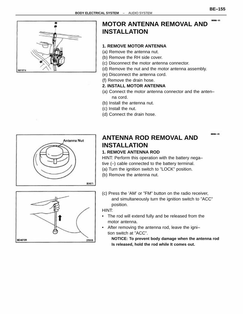
MOTOR ANTENNA REMOVAL ANDINSTALLATION
1. REMOVE MOTOR ANTENNA(a) Remove the antenna nut.(b) Remove the RH side cover.(c) Disconnect the motor antenna connector.(d) Remove the nut and the motor antenna assembly.(e) Disconnect the antenna cord.(f) Remove the drain hose.2. INSTALL MOTOR ANTENNA(a) Connect the motor antenna connector and the anten–
na cord.(b) Install the antenna nut.(c) Install the nut.(d) Connect the drain hose.
(c) Press the ’AM’ or ”FM” button on the radio receiver,and simultaneously turn the ignition switch to ”ACC”position.
HINT:• The rod will extend fully and be released from the
motor antenna.• After removing the antenna rod, leave the igni–
tion switch at ”ACC”.NOTICE: To prevent body damage when the antenna rodIs released, hold the rod while It comes out.
ANTENNA ROD REMOVAL ANDINSTALLATION1. REMOVE ANTENNA RODHINT: Perform this operation with the battery nega–tive (–) cable connected to the battery terminal.(a) Turn the ignition switch to ”LOCK” position.(b) Remove the antenna nut.
–BODY ELECTRICAL SYSTEM AUDIO SYSTEMBE–155
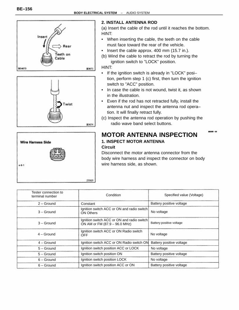
2. INSTALL ANTENNA ROD(a) Insert the cable of the rod until it reaches the bottom.HINT:• When inserting the cable, the teeth on the cable
must face toward the rear of the vehicle.• Insert the cable approx. 400 mm (15.7 in.).(b) Wind the cable to retract the rod by turning the
ignition switch to ”LOCK” position.HINT:• If the ignition switch is already in ”LOCK” posi–
tion, perform step 1 (c) first, then turn the ignitionswitch to ”ACC” position.
• In case the cable is not wound, twist it, as shownin the illustration.
• Even if the rod has not retracted fully, install theantenna nut and inspect the antenna rod opera–tion. It will finally retract fully.
(c) Inspect the antenna rod operation by pushing theradio wave band select buttons.
MOTOR ANTENNA INSPECTION1. INSPECT MOTOR ANTENNACircuitDisconnect the motor antenna connector from thebody wire harness and inspect the connector on bodywire harness side, as shown.
Ignition switch ACC or ON and radio switchON AM or FM (87.9 – 96.0 MHz)
Ignition switch ACC or ON Radio switchOFF
Ignition switch ACC or ON and radio switchON Others
Ignition switch ACC or ON Radio switch ON
Ignition switch position ACC or LOCK
Tester connection toterminal number
Ignition switch position ACC or ON
Ignition switch position LOCK
Ignition switch position ON
Specified value (Voltage)
Battery positive voltage
Battery positive voltage
Battery positive voltage
Battery positive voltage
Battery positive voltage
4 – Ground
5 – Ground
4 – Ground
5 – Ground
6 – Ground
2 – Ground
3 – Ground
6 – Ground
3 – Ground
No voltage
No voltage
No voltage
No voltage
Condition
Constant
–BODY ELECTRICAL SYSTEM AUDIO SYSTEMBE–156
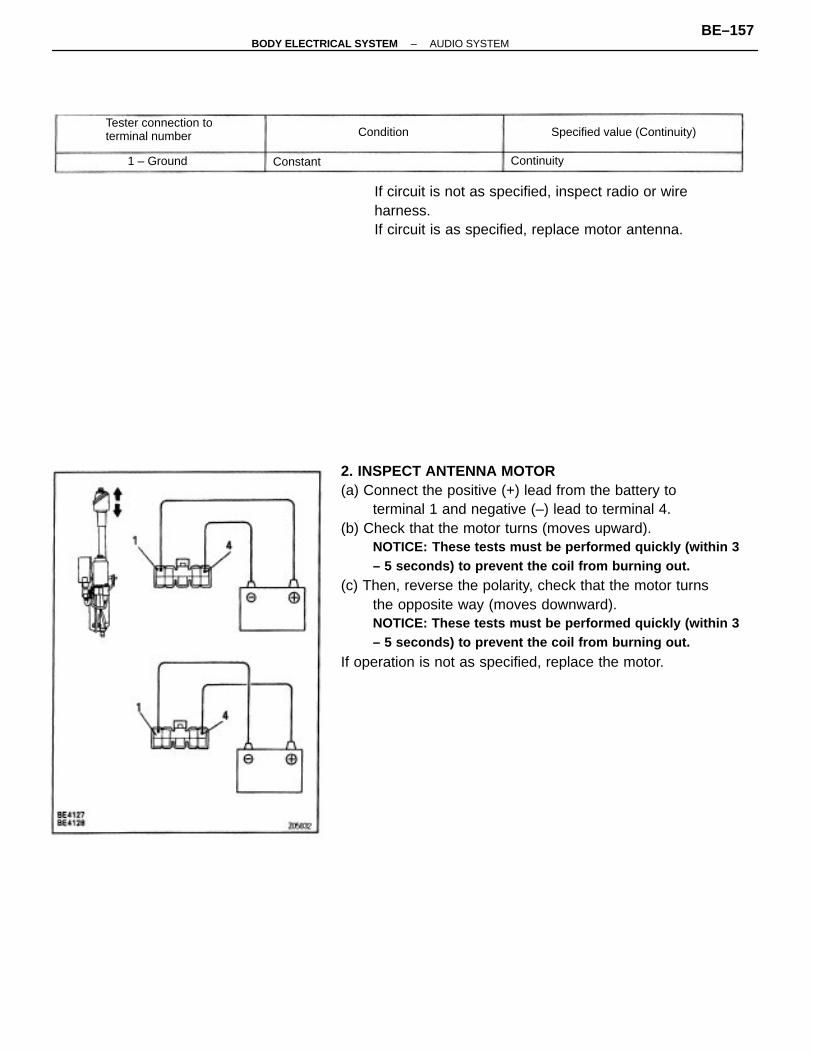
2. INSPECT ANTENNA MOTOR(a) Connect the positive (+) lead from the battery to
terminal 1 and negative (–) lead to terminal 4.(b) Check that the motor turns (moves upward).
NOTICE: These tests must be performed quickly (within 3– 5 seconds) to prevent the coil from burning out.
(c) Then, reverse the polarity, check that the motor turnsthe opposite way (moves downward).NOTICE: These tests must be performed quickly (within 3– 5 seconds) to prevent the coil from burning out.
If operation is not as specified, replace the motor.
If circuit is not as specified, inspect radio or wireharness.If circuit is as specified, replace motor antenna.
Tester connection toterminal number Specified value (Continuity)
1 – Ground Continuity
Condition
Constant
–BODY ELECTRICAL SYSTEM AUDIO SYSTEMBE–157
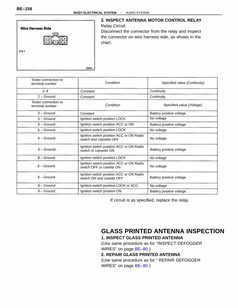
GLASS PRINTED ANTENNA INSPECTION1. INSPECT GLASS PRINTED ANTENNA(Use same procedure as for ”INSPECT DEFOGGERWIRES” on page BE–80.)2. REPAIR GLASS PRINTED ANTENNA(Use same procedure as for ” REPAIR DEFOGGERWIRES” on page BE–80.)
3. INSPECT ANTENNA MOTOR CONTROL RELAYRelay CircuitDisconnect the connector from the relay and inspectthe connector on wire harness side, as shown in thechart.
Ignition switch position ACC or ON Radioswitch ON and casette OFF
Ignition switch position ACC or ON Radioswitch and cassette OFF
Ignition switch position ACC or ON Radioswitch OFF or casette ON
Ignition switch position ACC or ON Radioswitch or cassette ON
If circuit is as specified, replace the relay.
Ignition switch position LOCK or ACC
Tester connection toterminal number
Tester connection toterminal number
Ignition switch position ACC or ON
Ignition switch position LOCK
Ignition switch position LOCK
Ignition switch position LOCK
Ignition switch position ON
Specified value (Continuity)
Specified value (Voltage)
Battery positive voltage
Battery positive voltage
Battery positive voltage
Battery positive voltage
Battery positive voltage
No voltage
8 – Ground
8 – Ground
8 – Ground
3 – Ground
No voltage
9 – Ground
5 – Ground
6 – Ground
2 – Ground
5 – Ground
6 – Ground
9 – Ground
6 – Ground
No voltage
No voltage
No voltage
No voltage
Continuity
Continuity
Condition
Condition
Constant
Constant
Constant1–4
–BODY ELECTRICAL SYSTEM AUDIO SYSTEMBE–158
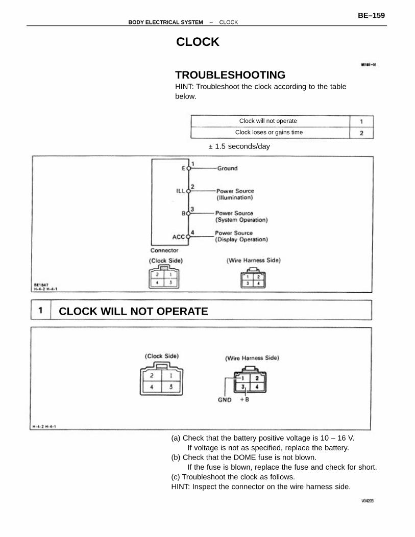
(a) Check that the battery positive voltage is 10 – 16 V.If voltage is not as specified, replace the battery.
(b) Check that the DOME fuse is not blown.If the fuse is blown, replace the fuse and check for short.
(c) Troubleshoot the clock as follows.HINT: Inspect the connector on the wire harness side.
TROUBLESHOOTINGHINT: Troubleshoot the clock according to the tablebelow.
CLOCK WILL NOT OPERATE
± 1.5 seconds/day
Clock loses or gains time
Clock will not operate
CLOCK
–BODY ELECTRICAL SYSTEM CLOCKBE–159
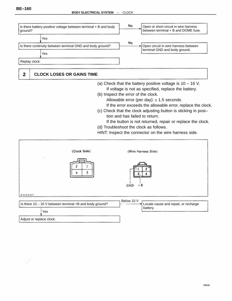
(a) Check that the battery positive voltage is 10 – 16 V.If voltage is not as specified, replace the battery.
(b) Inspect the error of the clock.Allowable error (per day): ± 1.5 secondsIf the error exceeds the allowable error, replace the clock.
(c) Check that the clock adjusting button is sticking in posi–tion and has failed to return.If the button is not returned, repair or replace the clock.
(d) Troubleshoot the clock as follows.HINT: Inspect the connector on the wire harness side.
Is there battery positive voltage between terminal + B and bodyground?
Is there continuity between terminal GND and body ground?
Open or short circuit in wire harnessbetween terminal + B and DOME fuse.
Open circuit in wire harness betweenterminal GND and body ground.
Locate cause and repair, or rechargebattery.
Is there 10 – 16 V between terminal +B and body ground?
CLOCK LOSES OR GAINS TIME
Adjust or replace clock.
Below 10 V
Replay clock.
Yes
Yes
Yes
–BODY ELECTRICAL SYSTEM CLOCKBE–160

– MEMO –
–BODY ELECTRICAL SYSTEM CLOCKBE–161

–MEMO –
–BODY ELECTRICAL SYSTEM CLOCKBE–162

CRUISE CONTROL SYSTEM
–BODY ELECTRICAL SYSTEM CRUISE CONTROL SYSTEMBE–163
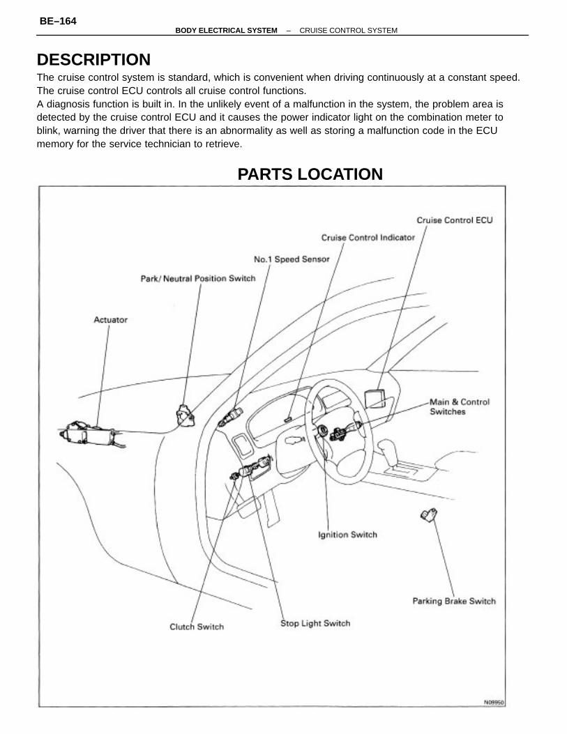
DESCRIPTIONThe cruise control system is standard, which is convenient when driving continuously at a constant speed.The cruise control ECU controls all cruise control functions.A diagnosis function is built in. In the unlikely event of a malfunction in the system, the problem area isdetected by the cruise control ECU and it causes the power indicator light on the combination meter toblink, warning the driver that there is an abnormality as well as storing a malfunction code in the ECUmemory for the service technician to retrieve.
PARTS LOCATION
–BODY ELECTRICAL SYSTEM CRUISE CONTROL SYSTEMBE–164
HOW TO PROCEED WITH TROUBLESHOOTINGPerform troubleshooting in accordance with the procedure on the following page.1. CUSTOMER PROBLEM ANALYSISUsing the customer problem analysis check sheet for reference, ask the customer in as much detail aspossible about the problem.2. CHECK AND CLEAR THE DIAGNOSTIC TROUBLE CODES (PRECHECK)When there is a problem with the cruise control being canceled or failing to set, first check thediagnostic trouble code if there are any trouble codes stored in memory. If there are trouble codes, makea note of them, then clear them and proceed to ”3 Problem Symptom Confirmation”.3. PROBLEM SYMPTOM CONFIRMATION, 4 SYMPTOM SIMULATIONConfirm the problem symptoms. If the problem does not reappear, be sure to simulate the problem bymainly checking the circuits indicated by the diagnostic trouble code in step 2, using ”ProblemSimulation Method”.5. DIAGNOSTIC TROUBLE CODE CHECKCheck the diagnostic trouble codes. Determine if the problem is in the sensors or the wire harness.If a malfunction code is present, proceed to ”6 Diagnostic Trouble Code Chart”. If the normal code isoutput, proceed to ”7 Matrix Chart Problem Symptoms”.Be sure to proceed to ”6 Diagnostic Trouble Code Chart” after 2 and 3 .If troubleshooting is attempted after only the first malfunction code in the memory is output, errorscould be made in the diagnosis.6. DIAGNOSTIC TROUBLE CODE CHARTIf a trouble code is confirmed in the diagnostic trouble code check, proceed to the check procedure indi–cated by the matrix chart for each diagnostic code.7. MATRIX CHART OF PROBLEM SYMPTOMSIf the normal code is confirmed in the diagnostic trouble code check, perform inspection in accordancewith the inspection order in the matrix chart of problem symptoms.8. CIRCUIT INSPECTIONProceed with diagnosis of each circuit in accordance with the inspection order in 6 and 7 .Determine whether the cause of the problem is in the sensor, actuators, wire harness and connectors,or the ECU.9. INPUT SIGNAL CHECKCheck whether signals from the stop light switch and park/neutral position switch, etc. are input nor–mally to the ECU. This check is indicated in the flow chart for each circuit.10. CONFIRMATION TESTAfter completing repairs, confirm not only that the malfunction is eliminated, but also perform a drivetest, etc. to make sure the entire cruise control system is operating correctly.
–BODY ELECTRICAL SYSTEM CRUISE CONTROL SYSTEMBE–165
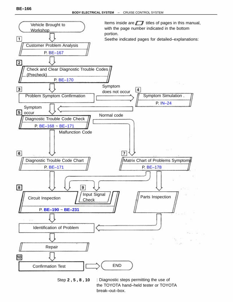
Items inside are titles of pages in this manual,with the page number indicated in the bottomportion.Seethe indicated pages for detailed–explanations:
: Diagnostic steps permitting the use ofthe TOYOTA hand–held tester or TOYOTAbreak–out–box.
Check and Clear Diagnostic Trouble Codes(Precheck)
Problem Symptom Confirmation
Matrix Chart of Problems Symptoms
Diagnostic Trouble Code Check
Diagnostic Trouble Code Chart
Vehicle Brought toWorkshop
Customer Problem Analysis
Symptomdoes not occur
Parts Inspection
Symptom Simulation .
Circuit Inspection
Malfunction Code
Identification of Problem
Symptomoccur
Input SignalCheck
P. BE–168 ~ BE–171
P. BE–190 ~ BE–231
Confirmation Test
Step 2 , 5 , 8 , 10
P. BE–178
Normal code
P. BE–167
P. BE–170
P. BE–171
P. IN–24
Repair
END
–BODY ELECTRICAL SYSTEM CRUISE CONTROL SYSTEMBE–166
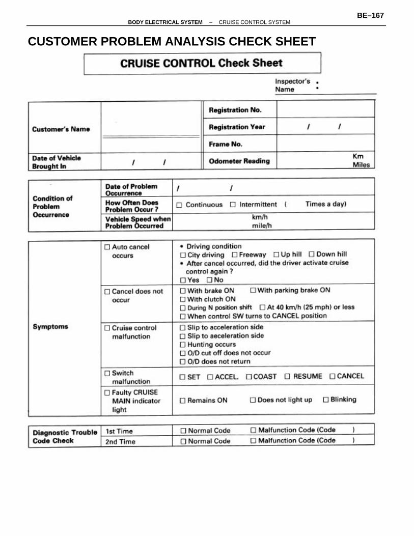
CUSTOMER PROBLEM ANALYSIS CHECK SHEET
–BODY ELECTRICAL SYSTEM CRUISE CONTROL SYSTEMBE–167
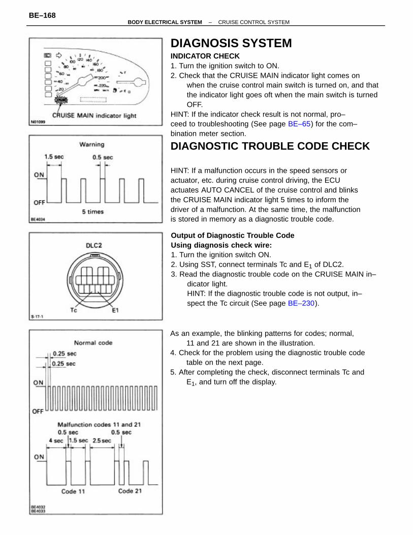
DIAGNOSIS SYSTEMINDICATOR CHECK1. Turn the ignition switch to ON.2. Check that the CRUISE MAIN indicator light comes on
when the cruise control main switch is turned on, and thatthe indicator light goes oft when the main switch is turnedOFF.
HINT: If the indicator check result is not normal, pro–ceed to troubleshooting (See page BE–65) for the com–bination meter section.
DIAGNOSTIC TROUBLE CODE CHECK
HINT: If a malfunction occurs in the speed sensors oractuator, etc. during cruise control driving, the ECUactuates AUTO CANCEL of the cruise control and blinksthe CRUISE MAIN indicator light 5 times to inform thedriver of a malfunction. At the same time, the malfunctionis stored in memory as a diagnostic trouble code.
Output of Diagnostic Trouble CodeUsing diagnosis check wire:1. Turn the ignition switch ON.2. Using SST, connect terminals Tc and E1 of DLC2.3. Read the diagnostic trouble code on the CRUISE MAIN in–
dicator light.HINT: If the diagnostic trouble code is not output, in–spect the Tc circuit (See page BE–230).
As an example, the blinking patterns for codes; normal,11 and 21 are shown in the illustration.
4. Check for the problem using the diagnostic trouble codetable on the next page.
5. After completing the check, disconnect terminals Tc andE1, and turn off the display.
–BODY ELECTRICAL SYSTEM CRUISE CONTROL SYSTEMBE–168
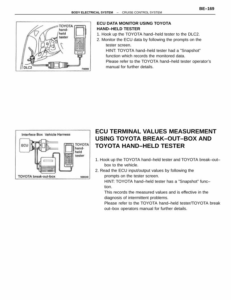
ECU TERMINAL VALUES MEASUREMENTUSING TOYOTA BREAK–OUT–BOX ANDTOYOTA HAND–HELD TESTER
1. Hook up the TOYOTA hand–held tester and TOYOTA break–out–box to the vehicle.
2. Read the ECU input/output values by following theprompts on the tester screen.HINT: TOYOTA hand–held tester has a ”Snapshot” func–tion.This records the measured values and is effective in thediagnosis of intermittent problems.Please refer to the TOYOTA hand–held tester/TOYOTA breakout–box operators manual for further details.
ECU DATA MONITOR USING TOYOTA HAND–HELD TESTER1. Hook up the TOYOTA hand–held tester to the DLC2.2. Monitor the ECU data by following the prompts on the
tester screen.HINT: TOYOTA hand–held tester had a ”Snapshot”function which records the monitored data.Please refer to the TOYOTA hand–held tester operator’smanual for further details.
–BODY ELECTRICAL SYSTEM CRUISE CONTROL SYSTEMBE–169
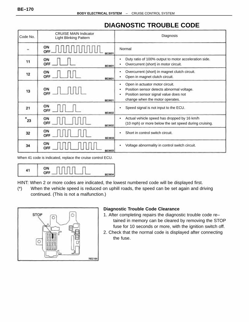
Diagnostic Trouble Code Clearance1. After completing repairs the diagnostic trouble code re–
tained in memory can be cleared by removing the STOPfuse for 10 seconds or more, with the ignition switch off.
2. Check that the normal code is displayed after connectingthe fuse.
HINT: When 2 or more codes are indicated, the lowest numbered code will be displayed first.(*) When the vehicle speed is reduced on uphill roads, the speed can be set again and driving
continued. (This is not a malfunction.)
• Open in actuator motor circuit.• Position sensor detects abnormal voltage.• Position sensor signal value does not
change when the motor operates.
• Actual vehicle speed has dropped by 16 km/h(10 mph) or more below the set speed during cruising.
• Duty ratio of 100% output to motor acceleration side.• Overcurrent (short) in motor circuit.
• Overcurrent (short) in magnet clutch circuit.• Open in magnet clutch circuit.
When 41 code is indicated, replace the cruise control ECU.
DIAGNOSTIC TROUBLE CODE
• Voltage abnormality in control switch circuit.
CRUISE MAIN IndicatorLight Blinking Pattern
• Speed signal is not input to the ECU.
• Short in control switch circuit.
DiagnosisCode No.
Normal
–BODY ELECTRICAL SYSTEM CRUISE CONTROL SYSTEMBE–170
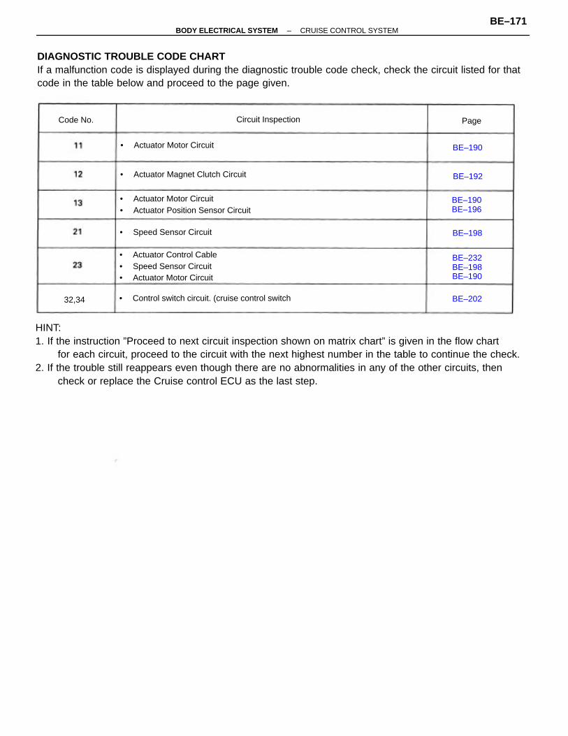
HINT:1. If the instruction ”Proceed to next circuit inspection shown on matrix chart” is given in the flow chart
for each circuit, proceed to the circuit with the next highest number in the table to continue the check.2. If the trouble still reappears even though there are no abnormalities in any of the other circuits, then
check or replace the Cruise control ECU as the last step.
DIAGNOSTIC TROUBLE CODE CHARTIf a malfunction code is displayed during the diagnostic trouble code check, check the circuit listed for thatcode in the table below and proceed to the page given.
• Actuator Control Cable• Speed Sensor Circuit• Actuator Motor Circuit
• Actuator Motor Circuit• Actuator Position Sensor Circuit
• Control switch circuit. (cruise control switch
• Actuator Magnet Clutch Circuit
• Speed Sensor Circuit
• Actuator Motor Circuit
Circuit Inspection
BE–232BE–198BE–190
BE–190BE–196
Code No.
BE–190
BE–202
BE–192
BE–198
32,34
Page
–BODY ELECTRICAL SYSTEM CRUISE CONTROL SYSTEMBE–171
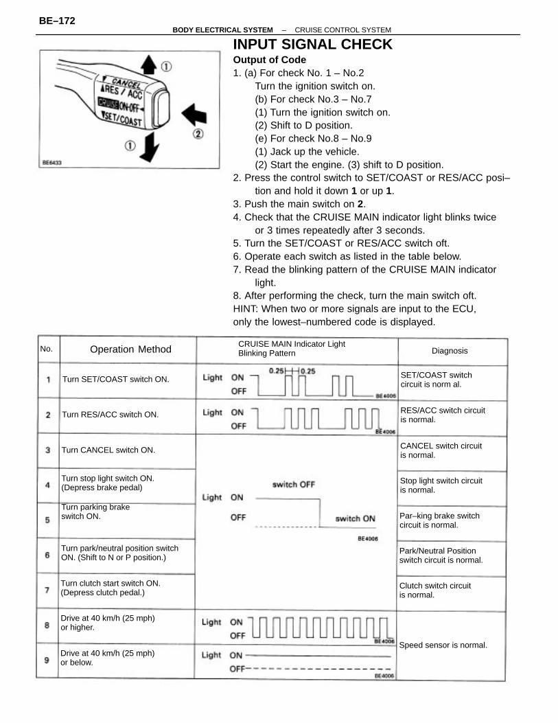
INPUT SIGNAL CHECKOutput of Code1. (a) For check No. 1 – No.2
Turn the ignition switch on.(b) For check No.3 – No.7(1) Turn the ignition switch on.(2) Shift to D position.(e) For check No.8 – No.9(1) Jack up the vehicle.(2) Start the engine. (3) shift to D position.
2. Press the control switch to SET/COAST or RES/ACC posi–tion and hold it down 1 or up 1.
3. Push the main switch on 2.4. Check that the CRUISE MAIN indicator light blinks twice
or 3 times repeatedly after 3 seconds.5. Turn the SET/COAST or RES/ACC switch oft.6. Operate each switch as listed in the table below.7. Read the blinking pattern of the CRUISE MAIN indicator
light.8. After performing the check, turn the main switch oft.HINT: When two or more signals are input to the ECU,only the lowest–numbered code is displayed.
Turn park/neutral position switchON. (Shift to N or P position.)
Turn clutch start switch ON.(Depress clutch pedal.)
CRUISE MAIN Indicator LightBlinking Pattern
Drive at 40 km/h (25 mph)or higher.
Turn stop light switch ON.(Depress brake pedal)
Drive at 40 km/h (25 mph)or below.
Park/Neutral Positionswitch circuit is normal.
RES/ACC switch circuitis normal.
Stop light switch circuitis normal.
Turn parking brakeswitch ON.
CANCEL switch circuitis normal.
Par–king brake switchcircuit is normal.
Clutch switch circuitis normal.
SET/COAST switchcircuit is norm al.
Turn SET/COAST switch ON.
Turn RES/ACC switch ON.
Turn CANCEL switch ON.
Speed sensor is normal.
Operation Method DiagnosisNo.
–BODY ELECTRICAL SYSTEM CRUISE CONTROL SYSTEMBE–172

– MEMO –
–BODY ELECTRICAL SYSTEM CRUISE CONTROL SYSTEMBE–173
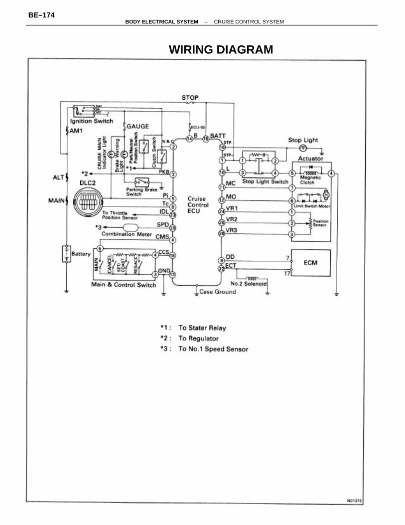
WIRING DIAGRAM
–BODY ELECTRICAL SYSTEM CRUISE CONTROL SYSTEMBE–174
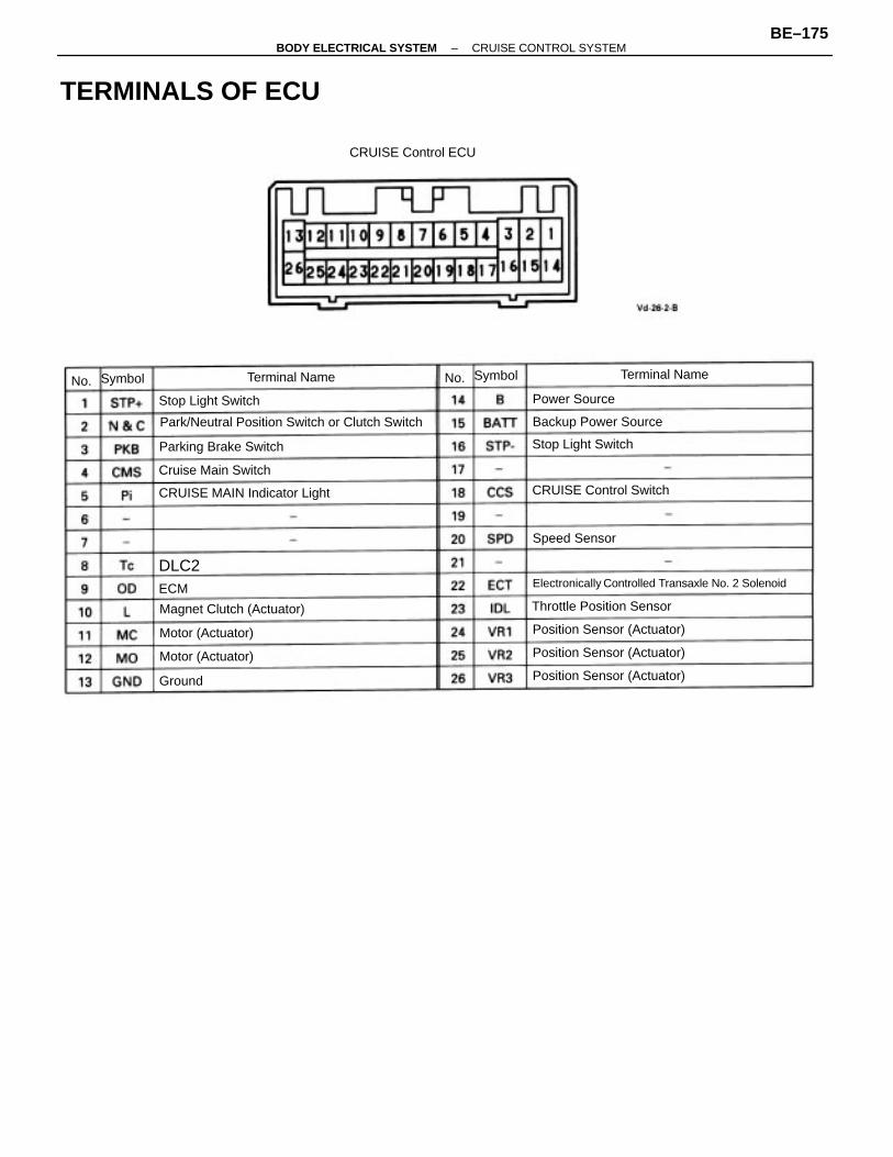
Park/Neutral Position Switch or Clutch Switch
Electronically Controlled Transaxle No. 2 Solenoid
TERMINALS OF ECU
CRUISE MAIN Indicator Light
Magnet Clutch (Actuator)
Position Sensor (Actuator)
Position Sensor (Actuator)
Position Sensor (Actuator)
Throttle Position Sensor
CRUISE Control Switch
Parking Brake Switch
Backup Power Source
CRUISE Control ECU
Cruise Main Switch
Stop Light Switch
Stop Light Switch
Motor (Actuator)
Motor (Actuator)
Terminal NameTerminal Name
Speed Sensor
Power Source
Symbol Symbol
Ground
DLC2ECM
No. No.
–BODY ELECTRICAL SYSTEM CRUISE CONTROL SYSTEMBE–175
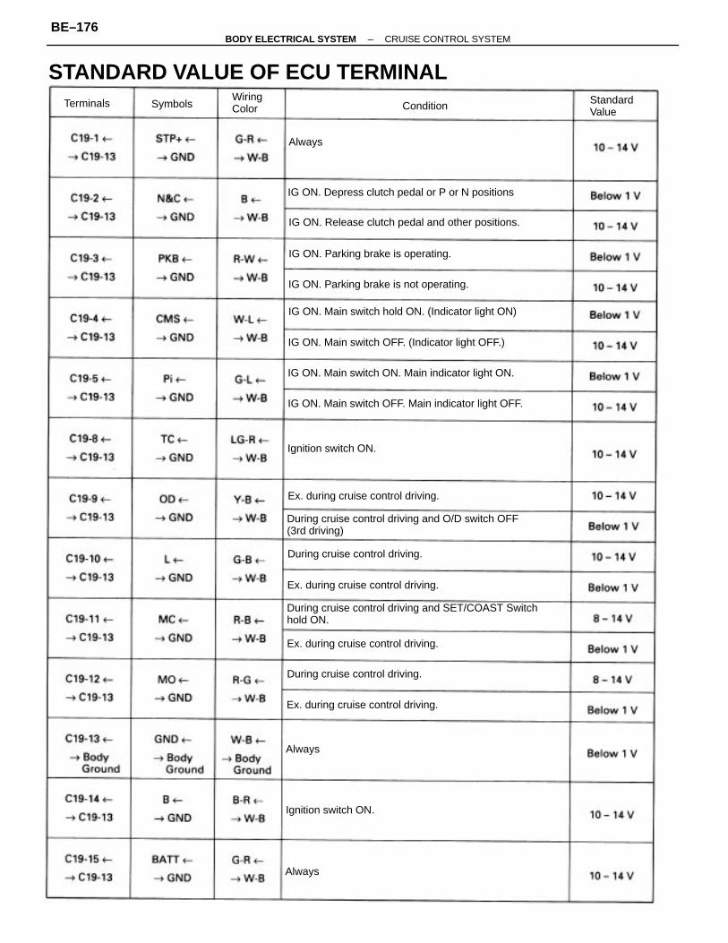
During cruise control driving and SET/COAST Switchhold ON.
During cruise control driving and O/D switch OFF(3rd driving)
STANDARD VALUE OF ECU TERMINAL
IG ON. Main switch OFF. Main indicator light OFF.
IG ON. Release clutch pedal and other positions.
IG ON. Main switch hold ON. (Indicator light ON)
IG ON. Main switch ON. Main indicator light ON.
IG ON. Depress clutch pedal or P or N positions
IG ON. Main switch OFF. (Indicator light OFF.)
IG ON. Parking brake is not operating.
IG ON. Parking brake is operating.
Ex. during cruise control driving.
Ex. during cruise control driving.
Ex. during cruise control driving.
Ex. during cruise control driving.
During cruise control driving.
During cruise control driving.
Ignition switch ON.
Ignition switch ON.
StandardValue
WiringColorTerminals ConditionSymbols
Always
Always
Always
–BODY ELECTRICAL SYSTEM CRUISE CONTROL SYSTEMBE–176
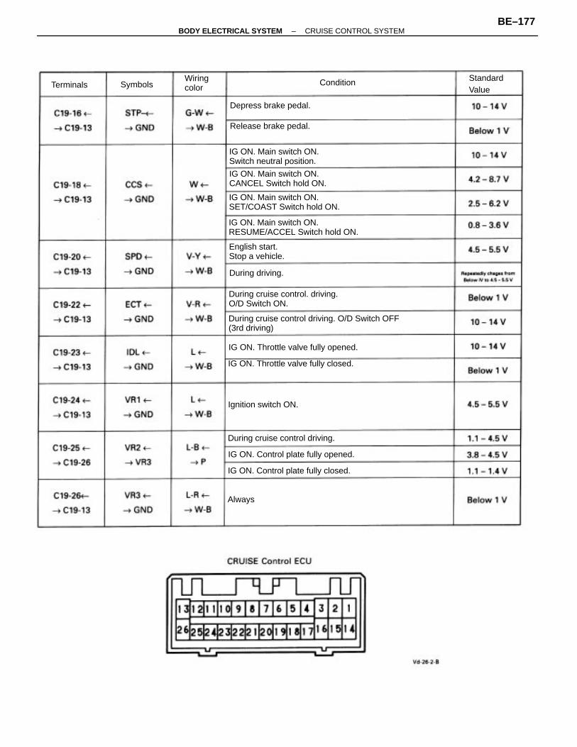
During cruise control driving. O/D Switch OFF(3rd driving)
IG ON. Main switch ON.RESUME/ACCEL Switch hold ON.
During cruise control. driving.O/D Switch ON.
IG ON. Throttle valve fully closed.
IG ON. Main switch ON.SET/COAST Switch hold ON.
IG ON. Main switch ON.CANCEL Switch hold ON.
IG ON. Main switch ON.Switch neutral position.
IG ON. Throttle valve fully opened.
IG ON. Control plate fully opened.
IG ON. Control plate fully closed.
During cruise control driving.
Release brake pedal.
English start.Stop a vehicle.
Depress brake pedal.
Ignition switch ON.
During driving.
StandardValue
Wiringcolor
ConditionTerminals Symbols
Always
–BODY ELECTRICAL SYSTEM CRUISE CONTROL SYSTEMBE–177
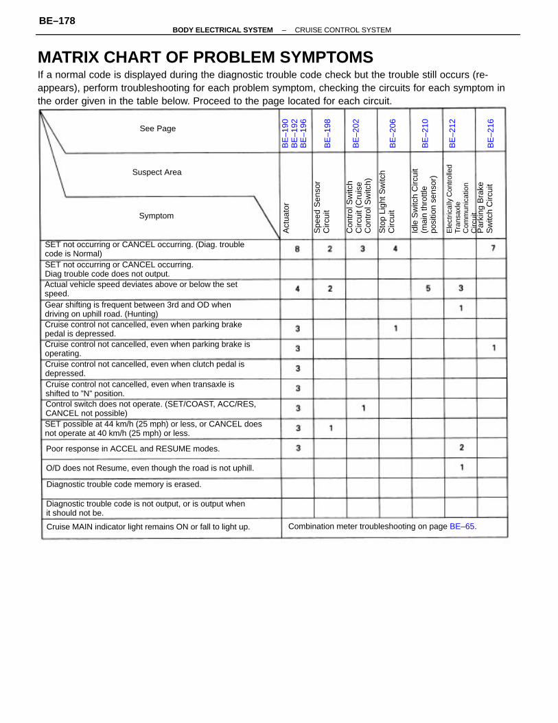
MATRIX CHART OF PROBLEM SYMPTOMSIf a normal code is displayed during the diagnostic trouble code check but the trouble still occurs (re-appears), perform troubleshooting for each problem symptom, checking the circuits for each symptom inthe order given in the table below. Proceed to the page located for each circuit.
SET possible at 44 km/h (25 mph) or less, or CANCEL doesnot operate at 40 km/h (25 mph) or less.
Cruise control not cancelled, even when parking brake isoperating.
SET not occurring or CANCEL occurring. (Diag. troublecode is Normal)
Control switch does not operate. (SET/COAST, ACC/RES,CANCEL not possible)
Diagnostic trouble code is not output, or is output whenit should not be.
Cruise control not cancelled, even when clutch pedal isdepressed.
Cruise control not cancelled, even when parking brakepedal is depressed.
Actual vehicle speed deviates above or below the setspeed.Gear shifting is frequent between 3rd and OD whendriving on uphill road. (Hunting)
Cruise control not cancelled, even when transaxle isshifted to ”N” position.
SET not occurring or CANCEL occurring.Diag trouble code does not output.
Cruise MAIN indicator light remains ON or fall to light up.
O/D does not Resume, even though the road is not uphill.
Diagnostic trouble code memory is erased.
Combination meter troubleshooting on page BE–65.
Poor response in ACCEL and RESUME modes.E
lect
rical
ly C
ontr
olle
dTr
ansa
xle
Com
mun
icat
ion
Circ
uit
Idle
Sw
itch
Circ
uit
(mai
n th
rottl
epo
sitio
n se
nsor
)
Con
trol
Sw
itch
Circ
uit (
Cru
ise
Con
trol
Sw
itch)
Sto
p Li
ght S
witc
hC
ircui
t
Par
king
Bra
keS
witc
h C
ircui
t
Spe
ed S
enso
rC
ircui
t
BE
–190
BE
–192
BE
–196
Suspect Area
See Page
Symptom
Act
uato
r
BE
–210
BE
–202
BE
–206
BE
–216
BE
–198
BE
–212
–BODY ELECTRICAL SYSTEM CRUISE CONTROL SYSTEMBE–178
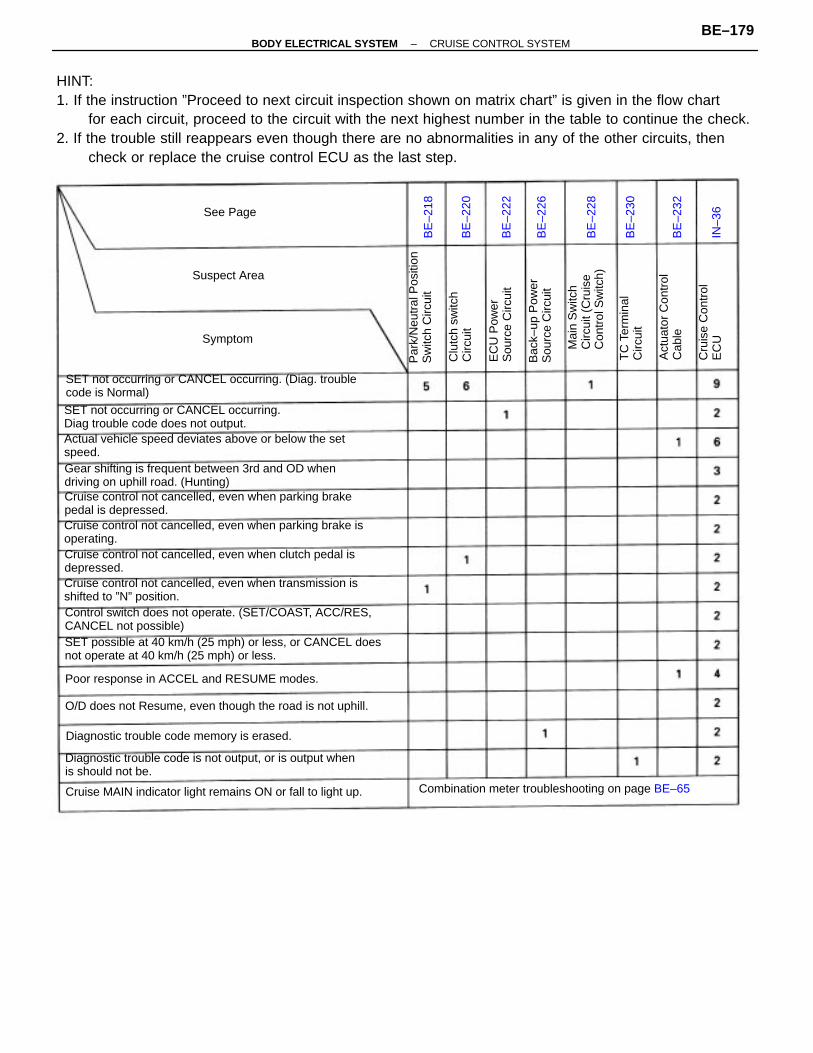
HINT:1. If the instruction ”Proceed to next circuit inspection shown on matrix chart” is given in the flow chart
for each circuit, proceed to the circuit with the next highest number in the table to continue the check.2. If the trouble still reappears even though there are no abnormalities in any of the other circuits, then
check or replace the cruise control ECU as the last step.
SET possible at 40 km/h (25 mph) or less, or CANCEL doesnot operate at 40 km/h (25 mph) or less.
SET not occurring or CANCEL occurring. (Diag. troublecode is Normal)
Cruise control not cancelled, even when parking brake isoperating.
Cruise control not cancelled, even when transmission isshifted to ”N” position.
Diagnostic trouble code is not output, or is output whenis should not be.
Control switch does not operate. (SET/COAST, ACC/RES,CANCEL not possible)
Cruise control not cancelled, even when clutch pedal isdepressed.
Cruise control not cancelled, even when parking brakepedal is depressed.
Actual vehicle speed deviates above or below the setspeed.Gear shifting is frequent between 3rd and OD whendriving on uphill road. (Hunting)
SET not occurring or CANCEL occurring.Diag trouble code does not output.
O/D does not Resume, even though the road is not uphill.
Cruise MAIN indicator light remains ON or fall to light up. Combination meter troubleshooting on page BE–65
Diagnostic trouble code memory is erased.
Poor response in ACCEL and RESUME modes.
Mai
n S
witc
hC
ircui
t (C
ruis
eC
ontr
ol S
witc
h)
Par
k/N
eutr
al P
ositi
onS
witc
h C
ircui
t
Act
uato
r C
ontr
olC
able
Bac
k–up
Pow
erS
ourc
e C
ircui
t
EC
U P
ower
Sou
rce
Circ
uit
Cru
ise
Con
trol
EC
U
Clu
tch
switc
hC
ircui
t
TC
Ter
min
alC
ircui
t
BE
–226
BE
–230
Suspect Area
Symptom
See Page
BE
–220
BE
–218
BE
–228
BE
–232
BE
–222
IN–3
6
–BODY ELECTRICAL SYSTEM CRUISE CONTROL SYSTEMBE–179
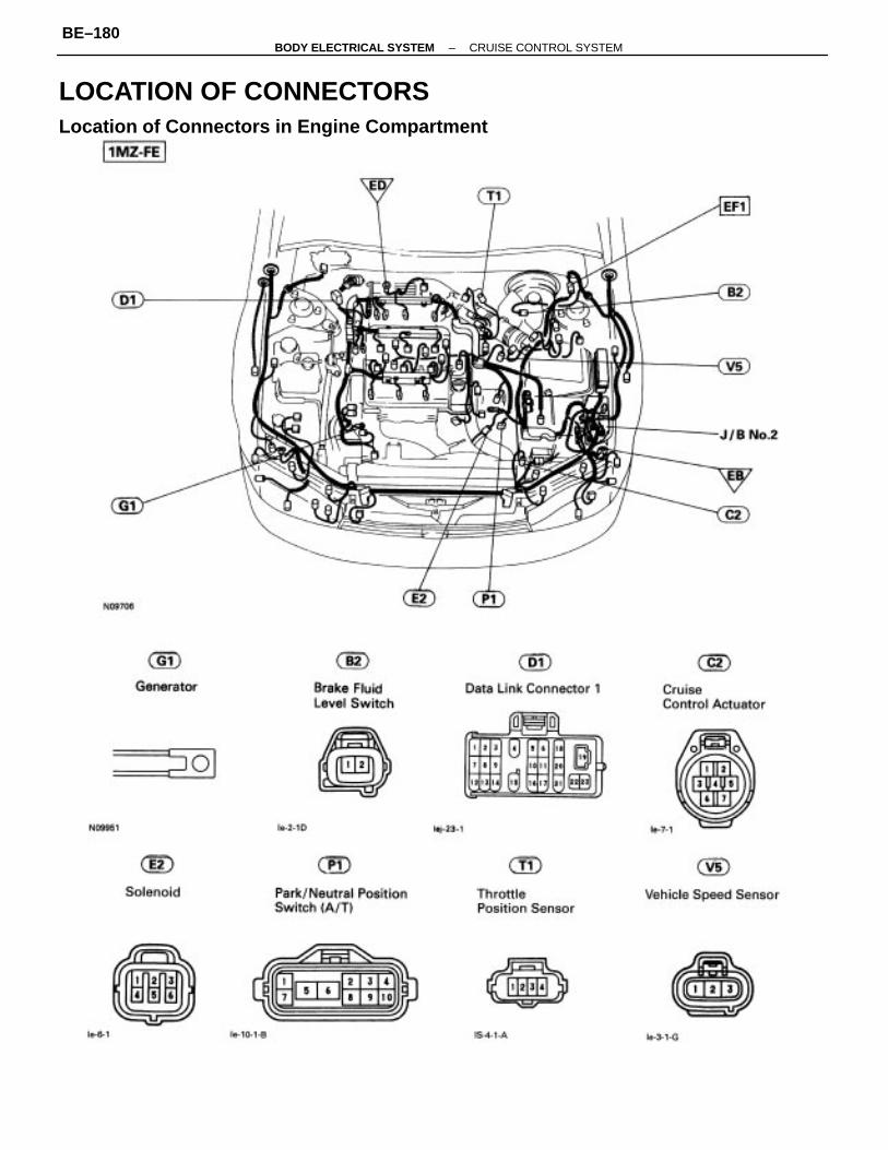
LOCATION OF CONNECTORSLocation of Connectors in Engine Compartment
–BODY ELECTRICAL SYSTEM CRUISE CONTROL SYSTEMBE–180
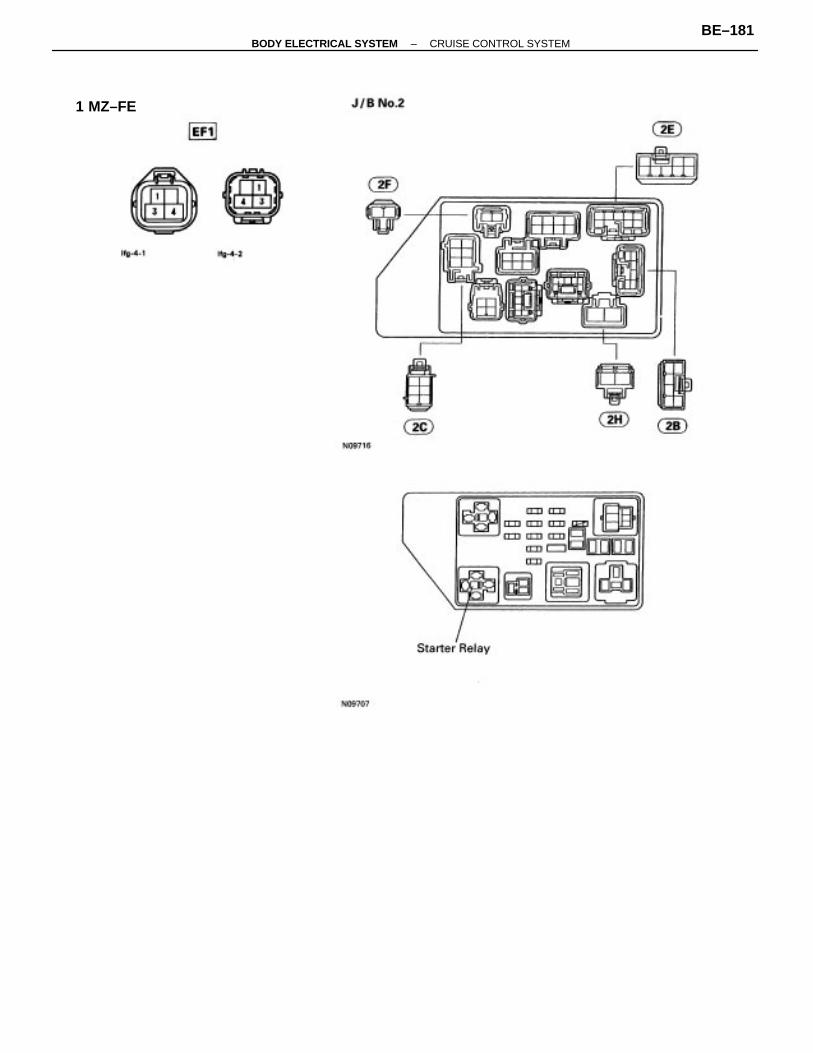
1 MZ–FE
–BODY ELECTRICAL SYSTEM CRUISE CONTROL SYSTEMBE–181
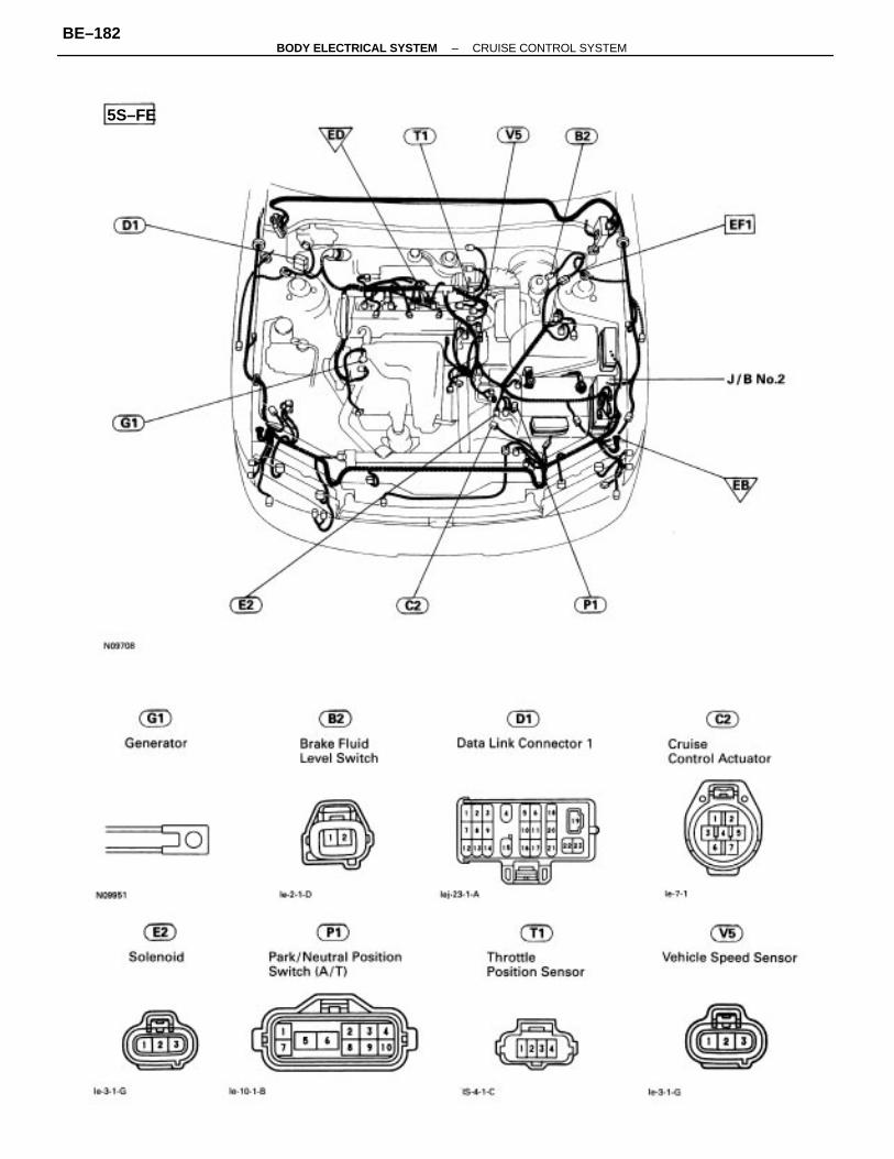
5S–FE
–BODY ELECTRICAL SYSTEM CRUISE CONTROL SYSTEMBE–182
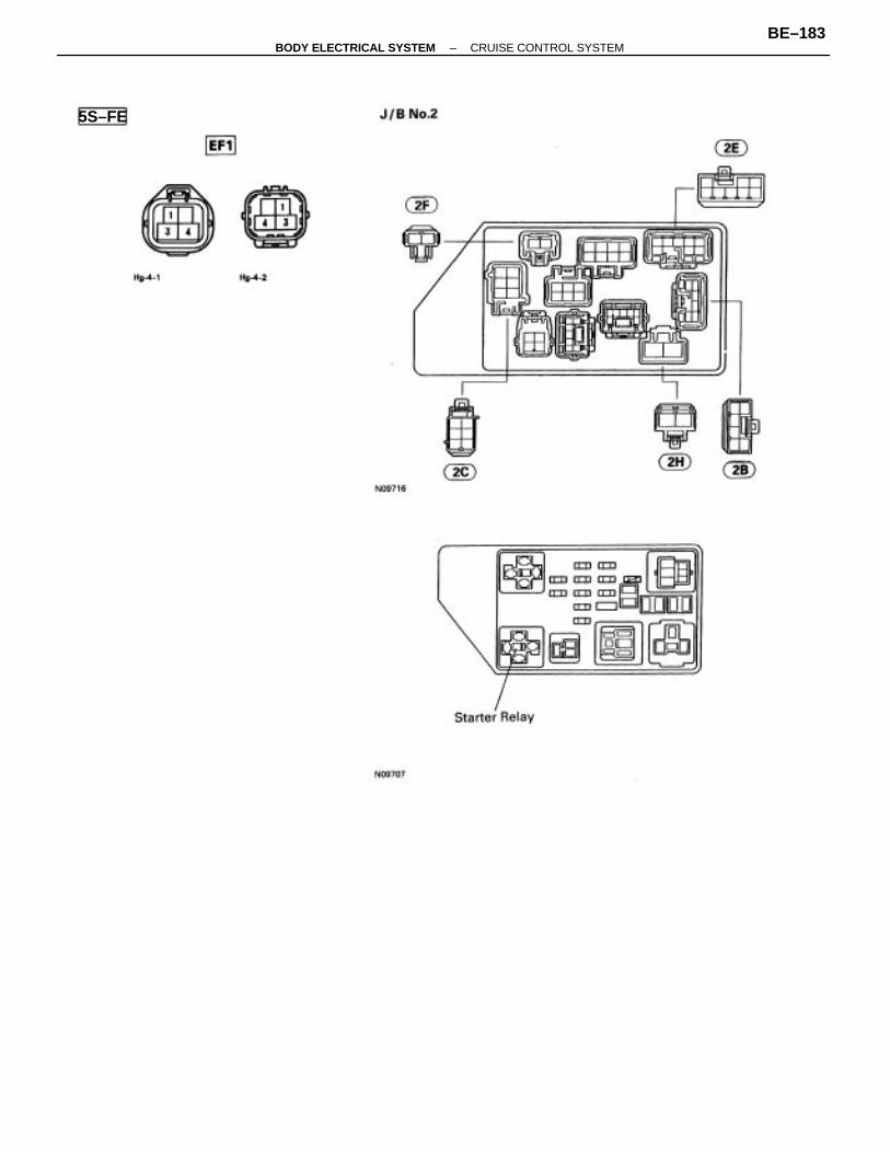
5S–FE
–BODY ELECTRICAL SYSTEM CRUISE CONTROL SYSTEMBE–183
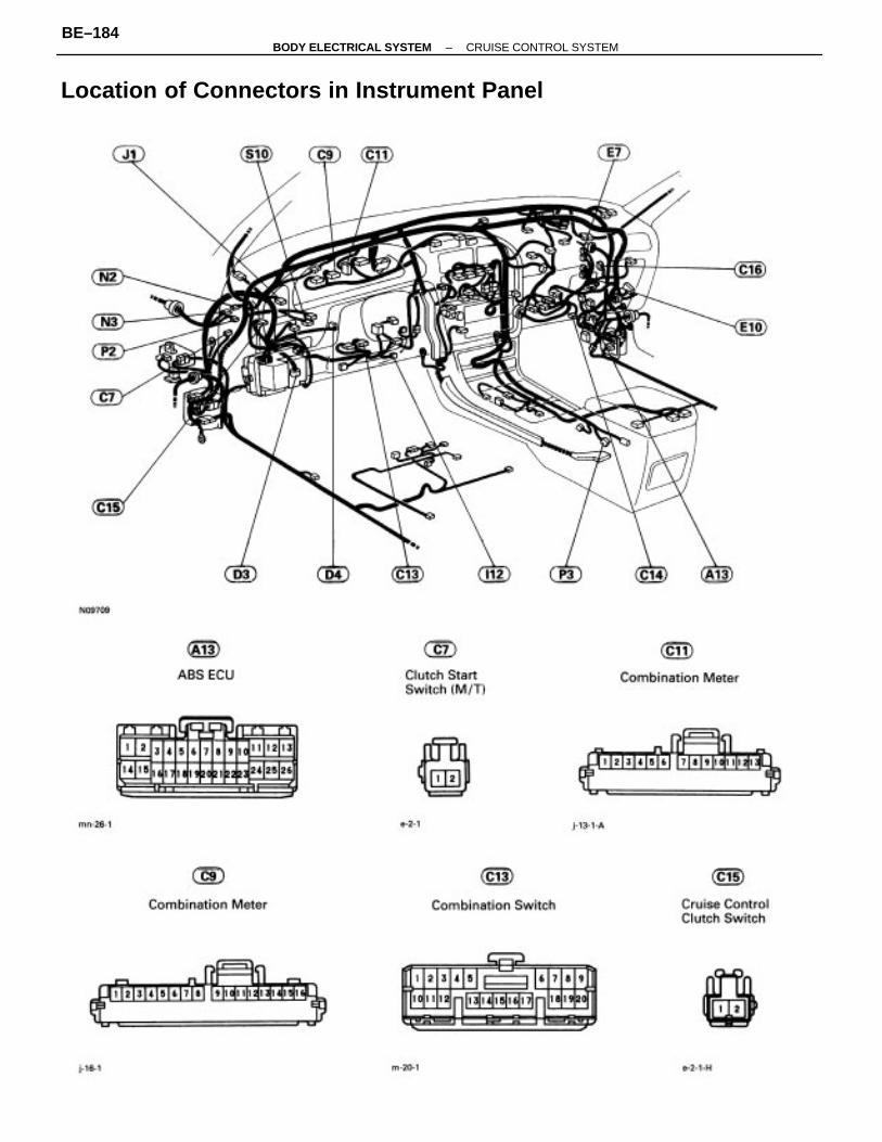
Location of Connectors in Instrument Panel
–BODY ELECTRICAL SYSTEM CRUISE CONTROL SYSTEMBE–184
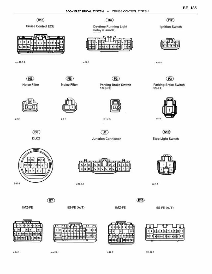
–BODY ELECTRICAL SYSTEM CRUISE CONTROL SYSTEMBE–185
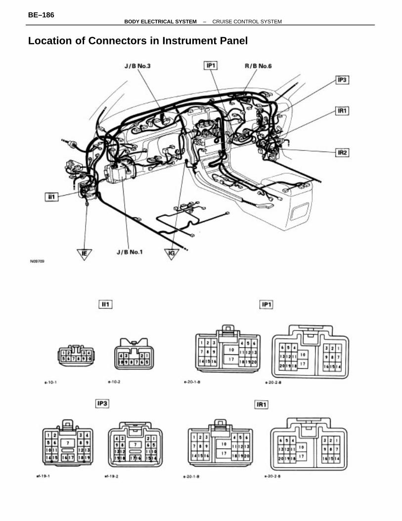
Location of Connectors in Instrument Panel
–BODY ELECTRICAL SYSTEM CRUISE CONTROL SYSTEMBE–186
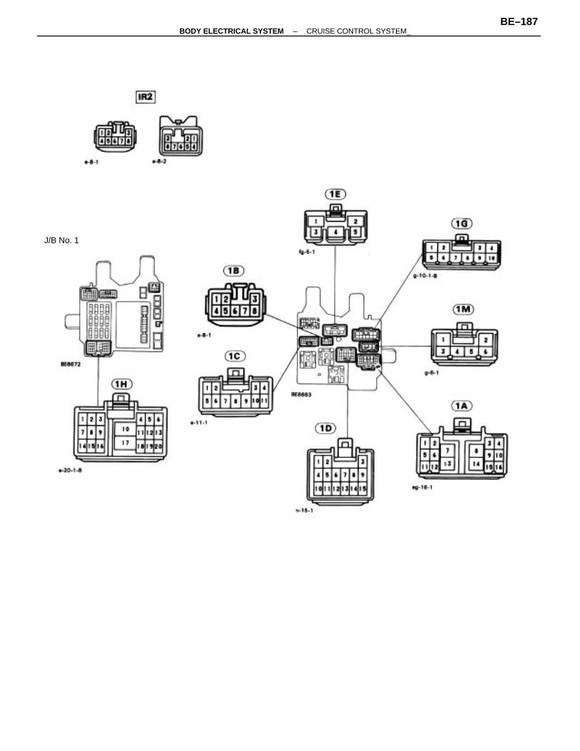
J/B No. 1
–BODY ELECTRICAL SYSTEM CRUISE CONTROL SYSTEM_BE–187
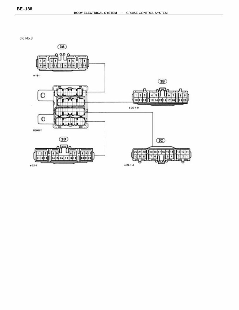
JI6 No.3
–BODY ELECTRICAL SYSTEM CRUISE CONTROL SYSTEMBE–188
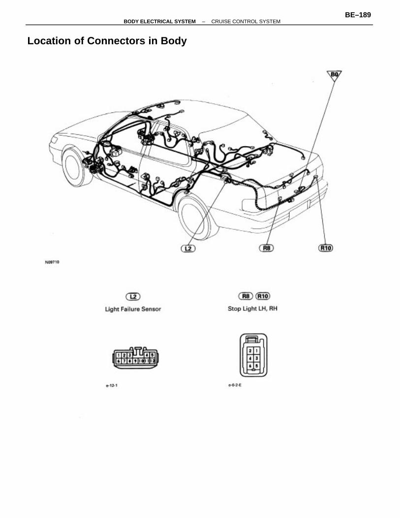
Location of Connectors in Body
–BODY ELECTRICAL SYSTEM CRUISE CONTROL SYSTEMBE–189
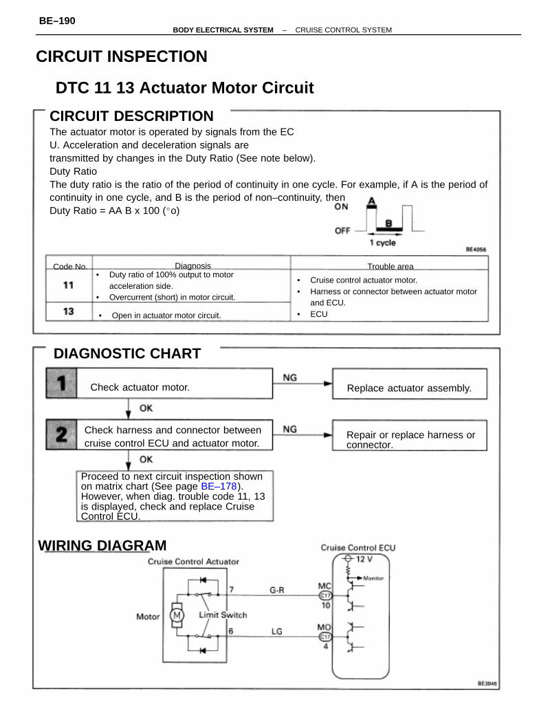
CIRCUIT DESCRIPTIONThe actuator motor is operated by signals from the ECU. Acceleration and deceleration signals aretransmitted by changes in the Duty Ratio (See note below).Duty RatioThe duty ratio is the ratio of the period of continuity in one cycle. For example, if A is the period ofcontinuity in one cycle, and B is the period of non–continuity, thenDuty Ratio = AA B x 100 (o)
Proceed to next circuit inspection shownon matrix chart (See page BE–178).However, when diag. trouble code 11, 13is displayed, check and replace CruiseControl ECU.
• Cruise control actuator motor.• Harness or connector between actuator motor
and ECU.• ECU
• Duty ratio of 100% output to motoracceleration side.
• Overcurrent (short) in motor circuit.
Check harness and connector betweencruise control ECU and actuator motor.
Repair or replace harness orconnector.
DTC 11 13 Actuator Motor Circuit
CIRCUIT INSPECTION
• Open in actuator motor circuit.
Replace actuator assembly.
DIAGNOSTIC CHART
WIRING DIAGRAM
Check actuator motor.
Trouble areaDiagnosisCode No.
CIRCUIT DESCRIPTION
–BODY ELECTRICAL SYSTEM CRUISE CONTROL SYSTEMBE–190
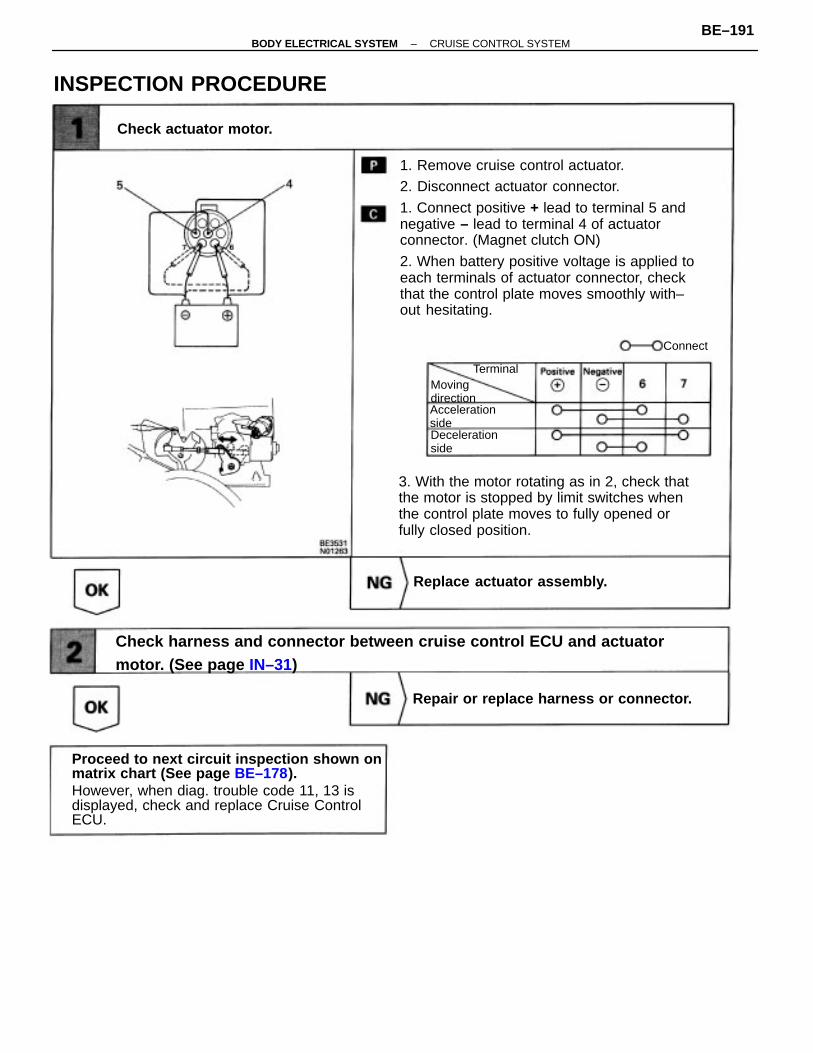
1. Remove cruise control actuator.2. Disconnect actuator connector.
1. Connect positive + lead to terminal 5 andnegative – lead to terminal 4 of actuatorconnector. (Magnet clutch ON)
2. When battery positive voltage is applied toeach terminals of actuator connector, checkthat the control plate moves smoothly with–out hesitating.
Proceed to next circuit inspection shown onmatrix chart (See page BE–178).However, when diag. trouble code 11, 13 isdisplayed, check and replace Cruise ControlECU.
Check harness and connector between cruise control ECU and actuatormotor. (See page IN–31)
3. With the motor rotating as in 2, check thatthe motor is stopped by limit switches whenthe control plate moves to fully opened orfully closed position.
Repair or replace harness or connector.
INSPECTION PROCEDURE
Replace actuator assembly.
Check actuator motor.
AccelerationsideDecelerationside
Movingdirection
Terminal
Connect
–BODY ELECTRICAL SYSTEM CRUISE CONTROL SYSTEMBE–191
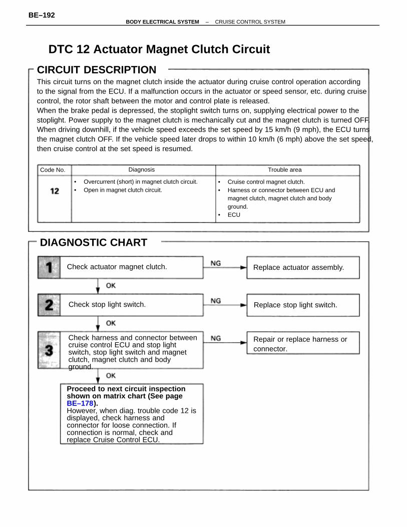
CIRCUIT DESCRIPTIONThis circuit turns on the magnet clutch inside the actuator during cruise control operation accordingto the signal from the ECU. If a malfunction occurs in the actuator or speed sensor, etc. during cruisecontrol, the rotor shaft between the motor and control plate is released.When the brake pedal is depressed, the stoplight switch turns on, supplying electrical power to thestoplight. Power supply to the magnet clutch is mechanically cut and the magnet clutch is turned OFF.When driving downhill, if the vehicle speed exceeds the set speed by 15 km/h (9 mph), the ECU turnsthe magnet clutch OFF. If the vehicle speed later drops to within 10 km/h (6 mph) above the set speed,then cruise control at the set speed is resumed.
Proceed to next circuit inspectionshown on matrix chart (See pageBE–178).However, when diag. trouble code 12 isdisplayed, check harness andconnector for loose connection. Ifconnection is normal, check andreplace Cruise Control ECU.
• Cruise control magnet clutch.• Harness or connector between ECU and
magnet clutch, magnet clutch and bodyground.
• ECU
Check harness and connector betweencruise control ECU and stop lightswitch, stop light switch and magnetclutch, magnet clutch and bodyground.
• Overcurrent (short) in magnet clutch circuit.• Open in magnet clutch circuit.
DTC 12 Actuator Magnet Clutch Circuit
Repair or replace harness orconnector.
Check actuator magnet clutch. Replace actuator assembly.
DIAGNOSTIC CHART
Replace stop light switch.Check stop light switch.
Trouble areaDiagnosisCode No.
CIRCUIT DESCRIPTION
–BODY ELECTRICAL SYSTEM CRUISE CONTROL SYSTEMBE–192
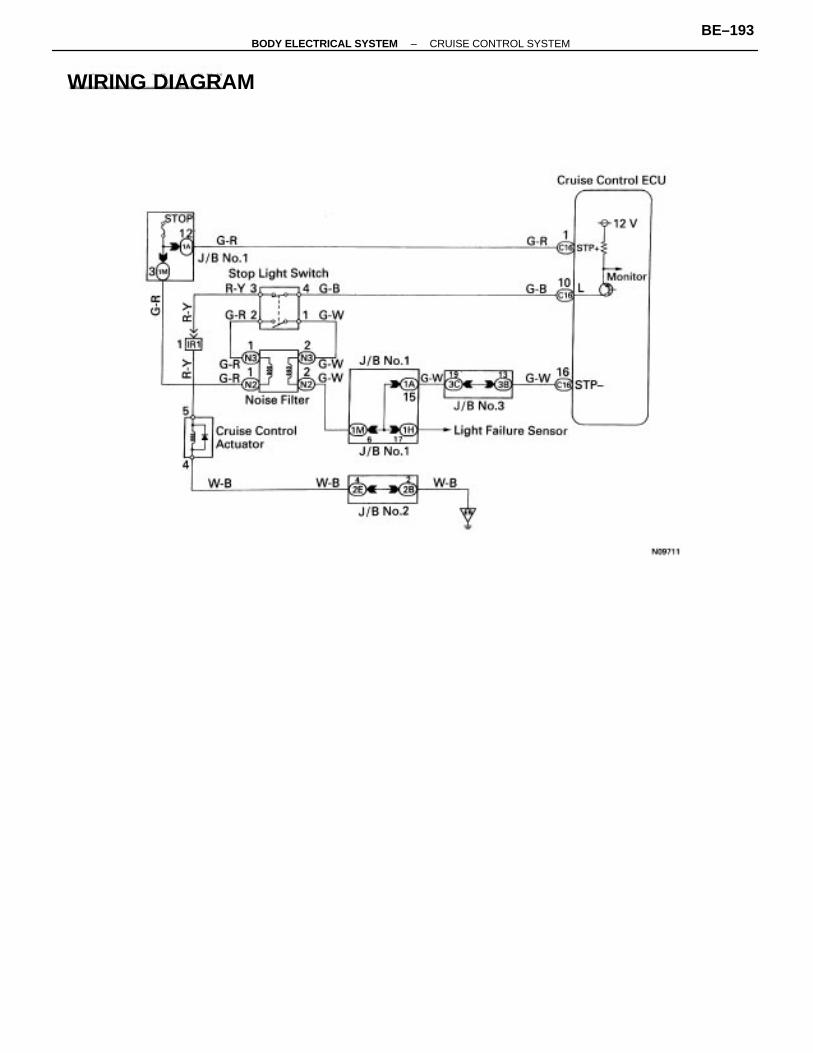
WIRING DIAGRAM
–BODY ELECTRICAL SYSTEM CRUISE CONTROL SYSTEMBE–193
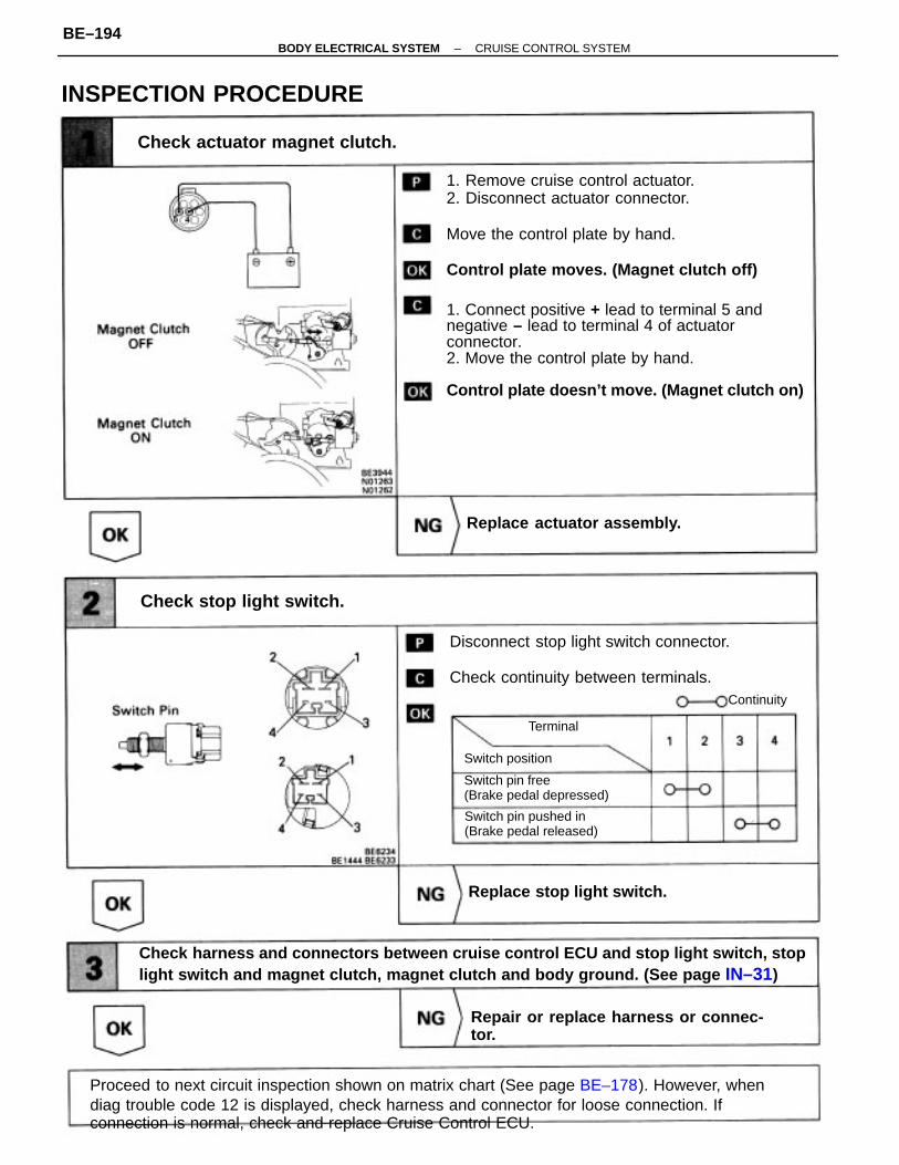
1. Remove cruise control actuator.2. Disconnect actuator connector.
Move the control plate by hand.
Control plate moves. (Magnet clutch off)
1. Connect positive + lead to terminal 5 andnegative – lead to terminal 4 of actuatorconnector.2. Move the control plate by hand.
Control plate doesn’t move. (Magnet clutch on)
Proceed to next circuit inspection shown on matrix chart (See page BE–178). However, whendiag trouble code 12 is displayed, check harness and connector for loose connection. Ifconnection is normal, check and replace Cruise Control ECU.
Check harness and connectors between cruise control ECU and stop light switch, stoplight switch and magnet clutch, magnet clutch and body ground. (See page IN–31)
Disconnect stop light switch connector.
Check continuity between terminals.
Check actuator magnet clutch.
Repair or replace harness or connec-tor.
Check stop light switch.
Switch pin free(Brake pedal depressed)
INSPECTION PROCEDURE
Switch pin pushed in(Brake pedal released)
Replace actuator assembly.
Replace stop light switch.
Switch position
Continuity
Terminal
–BODY ELECTRICAL SYSTEM CRUISE CONTROL SYSTEMBE–194

– MEMO –
–BODY ELECTRICAL SYSTEM CRUISE CONTROL SYSTEMBE–195
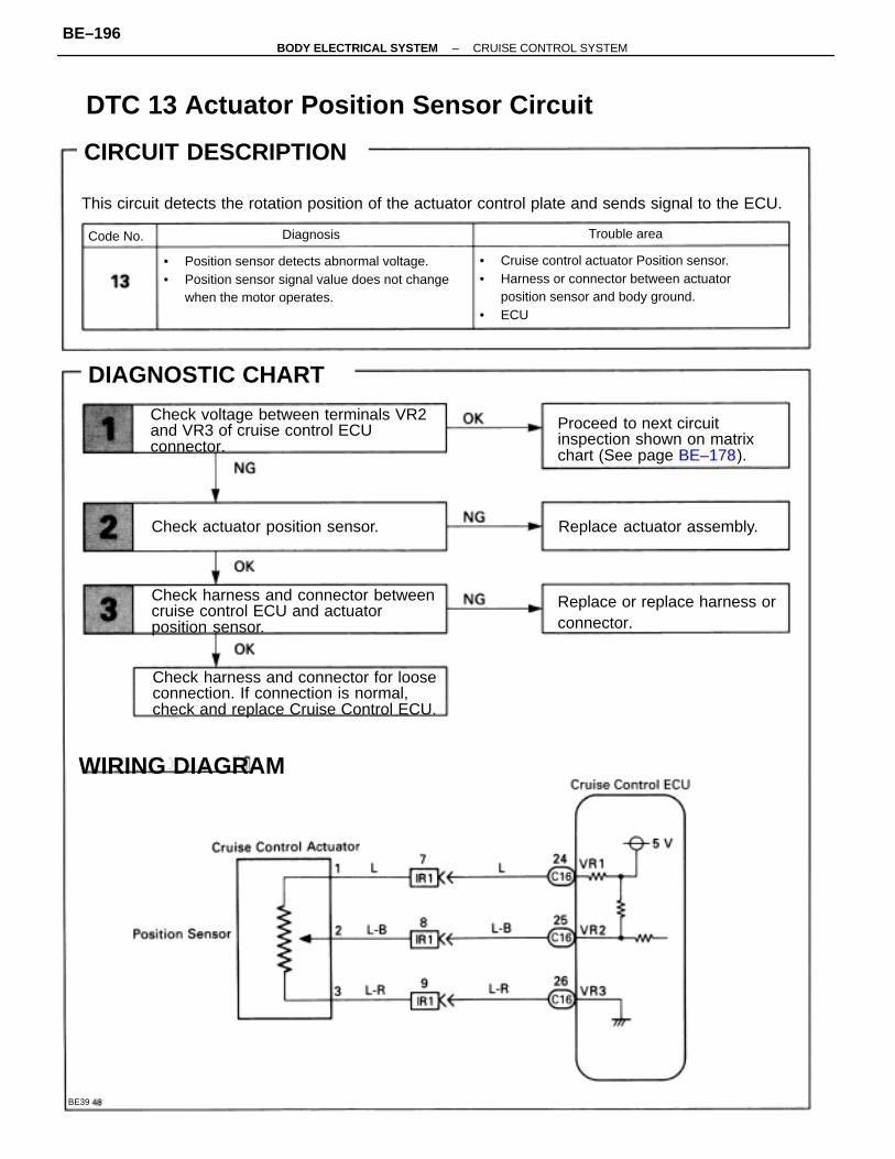
This circuit detects the rotation position of the actuator control plate and sends signal to the ECU.
• Cruise control actuator Position sensor.• Harness or connector between actuator
position sensor and body ground.• ECU
• Position sensor detects abnormal voltage.• Position sensor signal value does not change
when the motor operates.
Check harness and connector for looseconnection. If connection is normal,check and replace Cruise Control ECU.
Check harness and connector betweencruise control ECU and actuatorposition sensor.
Check voltage between terminals VR2and VR3 of cruise control ECUconnector.
DTC 13 Actuator Position Sensor Circuit
Proceed to next circuitinspection shown on matrixchart (See page BE–178).
Replace or replace harness orconnector.
Check actuator position sensor.
CIRCUIT DESCRIPTION
Replace actuator assembly.
DIAGNOSTIC CHART
WIRING DIAGRAM
Trouble areaDiagnosisCode No.
BE39
CIRCUIT DESCRIPTION
–BODY ELECTRICAL SYSTEM CRUISE CONTROL SYSTEMBE–196
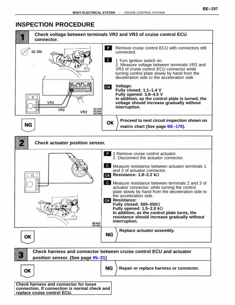
1 Remove cruise control actuator.2. Disconnect the actuator connector.
Measure resistance between actuator terminals 1and 3 of actuator connector.Resistance: 1.8–2.2 k Ω
Measure resistance between terminals 2 and 3 ofactuator connector, while turning the controlplate slowly by hand from the deceleration side tothe acceleration side.Resistance:Fully closed: 500–550 ΩFully opened: 1.5–2.0 k ΩIn addition, as the control plate turns, theresistance should increase gradually withoutinterruption.
Remove cruise control ECU with connectors stillconnected.
1 Turn ignition switch on.2. Measure voltage between terminals VR2 andVR3 of cruise control ECU connector whileturning control plate slowly by hand from thedeceleration side to the acceleration side.
Voltage:Fully closed: 1.1–1.4 VFully opened: 3.8–4.5 VIn addition, as the control plate is turned, thevoltage should increase gradually withoutinterruption.
Check harness and connector between cruise control ECU and actuatorposition sensor. (See page IN–31)
Check voltage between terminals VR2 and VR3 of cruise control ECUconnector.
Check harness and connector for looseconnection. If connection is normal check andreplace cruise control ECU.
Proceed to next circuit inspection shown onmatrix chart (See page BE–178).
Check actuator position sensor.
Replace actuator assembly.
Repair or replace harness or connector.
INSPECTION PROCEDURE
–BODY ELECTRICAL SYSTEM CRUISE CONTROL SYSTEMBE–197
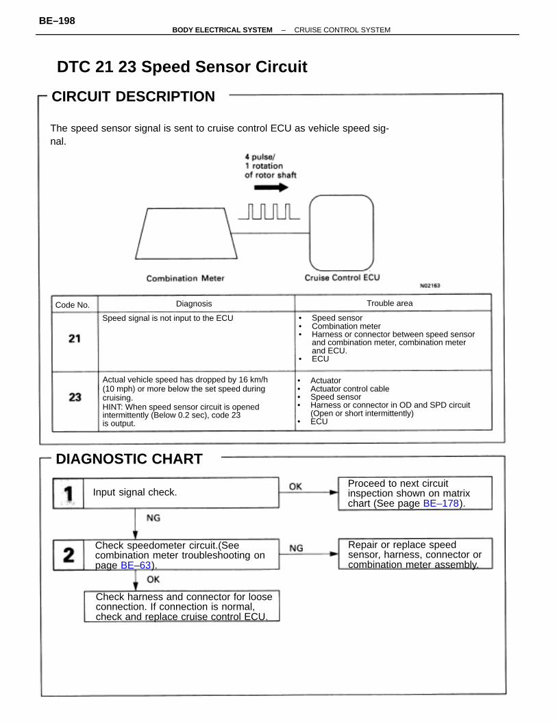
Actual vehicle speed has dropped by 16 km/h(10 mph) or more below the set speed duringcruising.HINT: When speed sensor circuit is openedintermittently (Below 0.2 sec), code 23is output.
• Speed sensor• Combination meter• Harness or connector between speed sensor
and combination meter, combination meterand ECU.
• ECU
• Actuator• Actuator control cable• Speed sensor• Harness or connector in OD and SPD circuit
(Open or short intermittently)• ECU
The speed sensor signal is sent to cruise control ECU as vehicle speed sig-nal.
Check speedometer circuit.(Seecombination meter troubleshooting onpage BE–63).
Check harness and connector for looseconnection. If connection is normal,check and replace cruise control ECU.
Repair or replace speedsensor, harness, connector orcombination meter assembly.
Proceed to next circuitinspection shown on matrixchart (See page BE–178).
DTC 21 23 Speed Sensor Circuit
Speed signal is not input to the ECU
CIRCUIT DESCRIPTION
DIAGNOSTIC CHART
Input signal check.
Trouble areaDiagnosisCode No.
CIRCUIT DESCRIPTION
–BODY ELECTRICAL SYSTEM CRUISE CONTROL SYSTEMBE–198
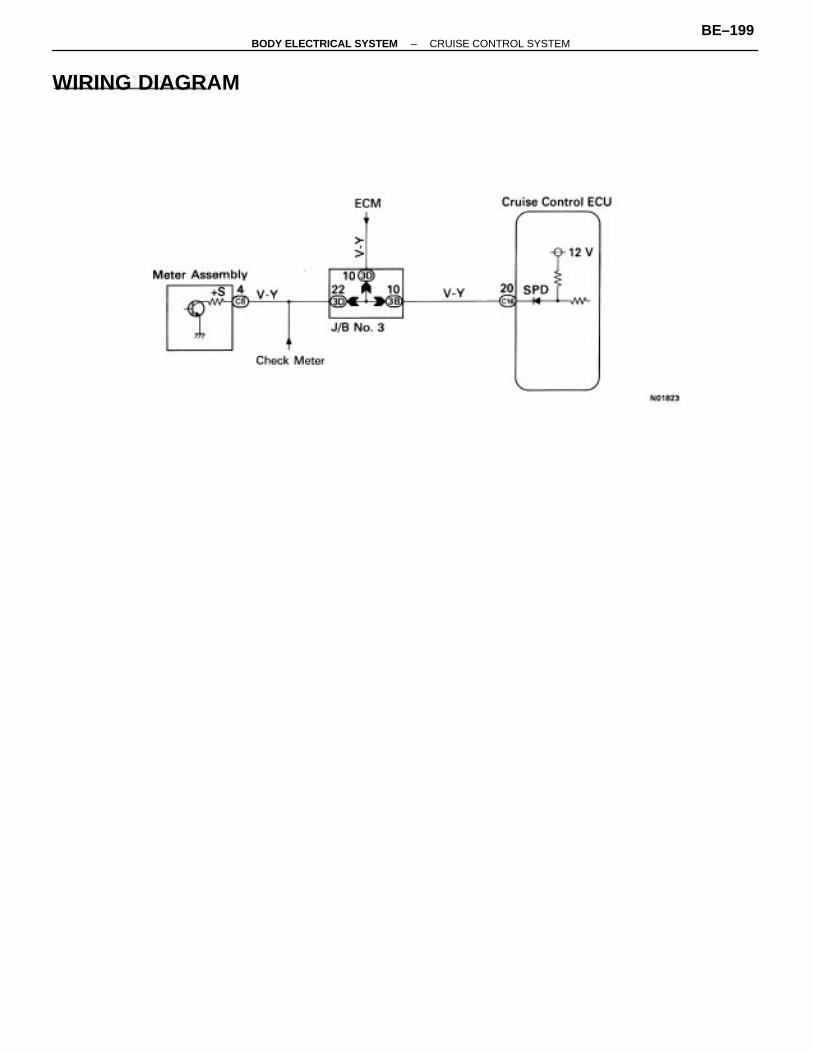
WIRING DIAGRAM
–BODY ELECTRICAL SYSTEM CRUISE CONTROL SYSTEMBE–199
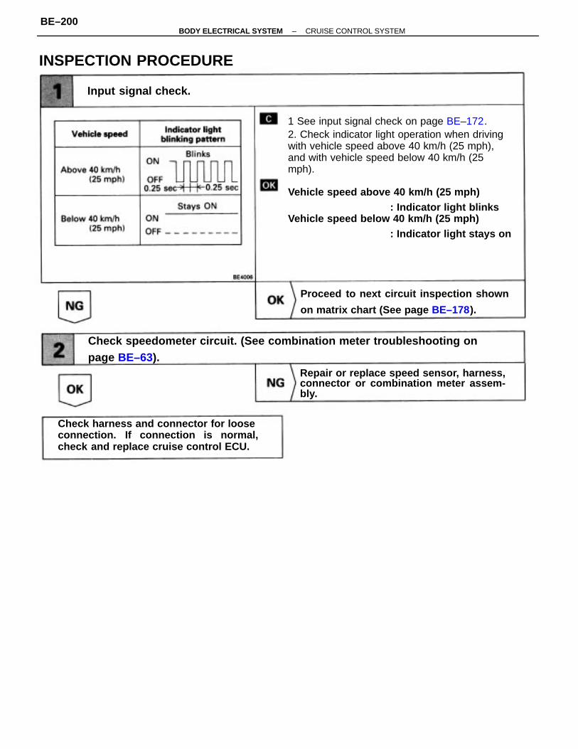
1 See input signal check on page BE–172.2. Check indicator light operation when drivingwith vehicle speed above 40 km/h (25 mph),and with vehicle speed below 40 km/h (25mph).
Vehicle speed above 40 km/h (25 mph): Indicator light blinks
Vehicle speed below 40 km/h (25 mph): Indicator light stays on
Check speedometer circuit. (See combination meter troubleshooting onpage BE–63).
Check harness and connector for looseconnection. If connection is normal,check and replace cruise control ECU.
Proceed to next circuit inspection shown
on matrix chart (See page BE–178).
Repair or replace speed sensor, harness,connector or combination meter assem-bly.
INSPECTION PROCEDURE
Input signal check.
–BODY ELECTRICAL SYSTEM CRUISE CONTROL SYSTEMBE–200

– MEMO –
–BODY ELECTRICAL SYSTEM CRUISE CONTROL SYSTEMBE–201
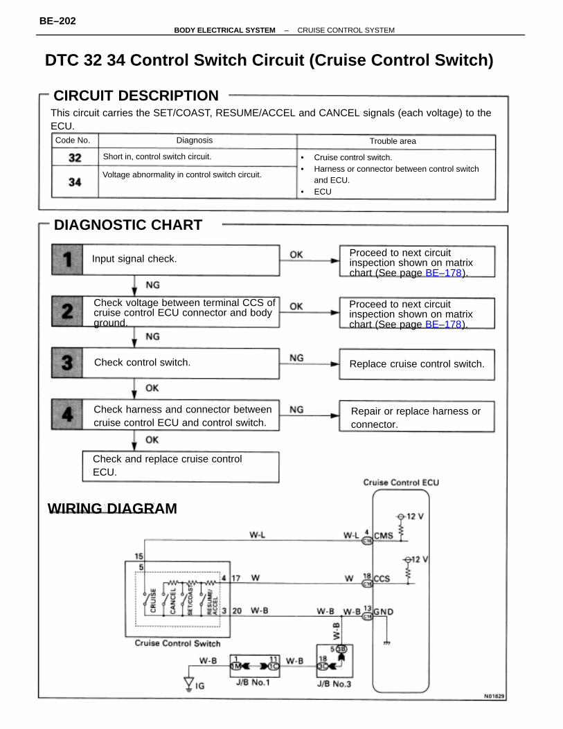
DTC 32 34 Control Switch Circuit (Cruise Control Switch)
This circuit carries the SET/COAST, RESUME/ACCEL and CANCEL signals (each voltage) to theECU.
• Cruise control switch.• Harness or connector between control switch
and ECU.• ECU
Check voltage between terminal CCS ofcruise control ECU connector and bodyground.
Check harness and connector betweencruise control ECU and control switch.
Proceed to next circuitinspection shown on matrixchart (See page BE–178).
Proceed to next circuitinspection shown on matrixchart (See page BE–178).
Repair or replace harness orconnector.
Voltage abnormality in control switch circuit.
Check and replace cruise controlECU.
CIRCUIT DESCRIPTION
Replace cruise control switch.
DIAGNOSTIC CHART
Short in, control switch circuit.
WIRING DIAGRAM
Check control switch.
Input signal check.
Trouble areaDiagnosisCode No.
CIRCUIT DESCRIPTION
–BODY ELECTRICAL SYSTEM CRUISE CONTROL SYSTEMBE–202
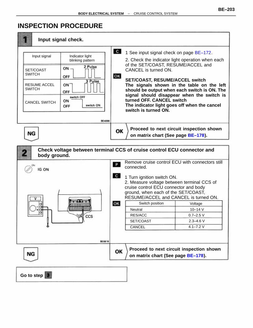
1 See input signal check on page BE–172.
2. Check the indicator light operation when eachof the SET/COAST, RESUME/ACCEL andCANCEL is turned ON.
SET/COAST, RESUME/ACCEL switchThe signals shown in the table on the leftshould be output when each switch is ON. Thesignal should disappear when the switch isturned OFF. CANCEL switchThe indicator light goes off when the cancelswitch is turned ON.
Remove cruise control ECU with connectors stillconnected.
1 Turn ignition switch ON.2. Measure voltage between terminal CCS ofcruise control ECU connector and bodyground, when each of the SET/COAST,RESUME/ACCEL and CANCEL is turned ON.
Check voltage between terminal CCS of cruise control ECU connector andbody ground.
Proceed to next circuit inspection shownon matrix chart (See page BE–178).
Proceed to next circuit inspection shownon matrix chart (See page BE–178).
INSPECTION PROCEDURE
Input signal check.
Indicator lightblinking pattern
RESUME ACCELSWITCH
SET/COASTSWITCH
CANCEL SWITCH
Switch position
Input signal
Go to step
SET/COAST
RES/ACC 0.7–2.5 V
4.1–7.2 V
2.3–4.6 V
Voltage
CANCEL
10–14 VNeutral
–BODY ELECTRICAL SYSTEM CRUISE CONTROL SYSTEMBE–203
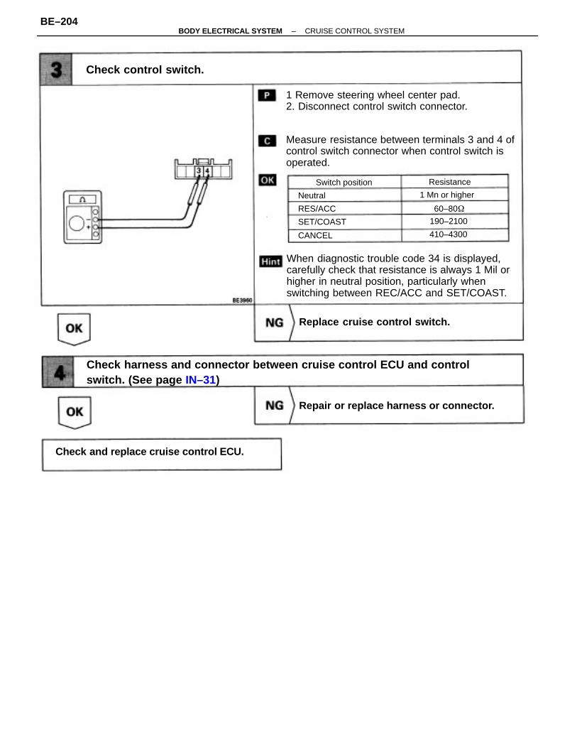
Check harness and connector between cruise control ECU and controlswitch. (See page IN–31)
When diagnostic trouble code 34 is displayed,carefully check that resistance is always 1 Mil orhigher in neutral position, particularly whenswitching between REC/ACC and SET/COAST.
Measure resistance between terminals 3 and 4 ofcontrol switch connector when control switch isoperated.
1 Remove steering wheel center pad.2. Disconnect control switch connector.
Check and replace cruise control ECU.
Repair or replace harness or connector.
Replace cruise control switch.
Check control switch.
Switch position
1 Mn or higher
SET/COAST
Resistance
410–4300
190–2100
RES/ACC
CANCEL
60–80
Neutral
–BODY ELECTRICAL SYSTEM CRUISE CONTROL SYSTEMBE–204

– MEMO –
–BODY ELECTRICAL SYSTEM CRUISE CONTROL SYSTEMBE–205
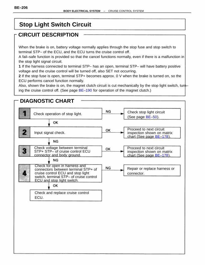
CIRCUIT DESCRIPTION
When the brake is on, battery voltage normally applies through the stop fuse and stop switch toterminal STP– of the ECU, and the ECU turns the cruise control off.A fail–safe function is provided so that the cancel functions normally, even if there is a malfunction inthe stop light signal circuit.1 If the harness connected to terminal STP– has an open, terminal STP– will have battery positivevoltage and the cruise control will be turned off, also SET not occurring.2 If the stop fuse is open, terminal STP+ becomes approx. 0 V when the brake is turned on, so theECU performs cancel function normally.Also, shown the brake is on, the magnet clutch circuit is cut mechanically by the stop light switch, turn–ing the cruise control off. (See page BE–190 for operation of the magnet clutch.)
Check for open in harness andconnectors between terminal STP+ ofcruise control ECU and stop lightswitch, terminal STP– of cruise controlECU and stop Iight switch.
Check voltage between terminalSTP+ STP– of cruise control ECUconnector and body ground.
Proceed to next circuitinspection shown on matrixchart (See page BE–178).
Proceed to next circuitinspection shown on matrixchart (See page BE–178).
Stop Light Switch Circuit
Repair or replace harness orconnector.
Check stop light circuit(See page BE–50).
Check and replace cruise controlECU.
Check operation of stop light.
DIAGNOSTIC CHART
Input signal check.
CIRCUIT DESCRIPTION
–BODY ELECTRICAL SYSTEM CRUISE CONTROL SYSTEMBE–206
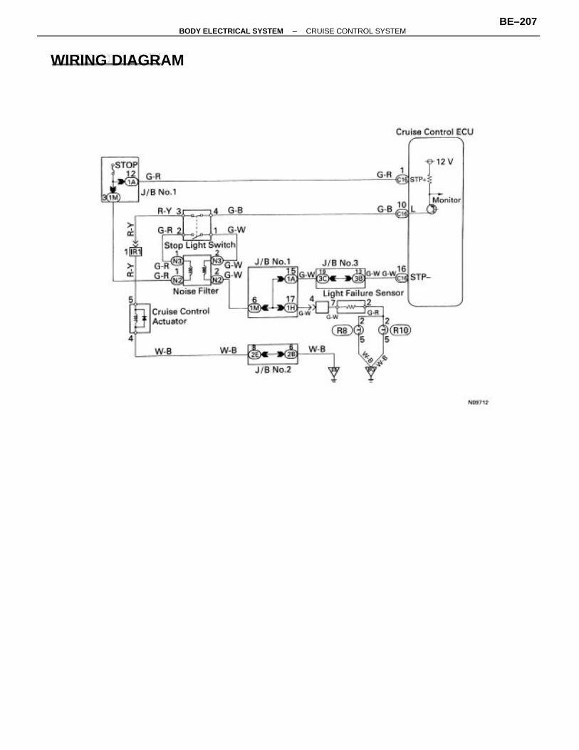
WIRING DIAGRAM
–BODY ELECTRICAL SYSTEM CRUISE CONTROL SYSTEMBE–207
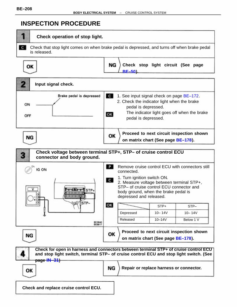
Remove cruise control ECU with connectors stillconnected.
1. Turn ignition switch ON.2. Measure voltage between terminal STP+,STP– of cruise control ECU connector andbody ground, when the brake pedal isdepressed and released.
1. See input signal check on page BE–172.2. Check the indicator light when the brake
pedal is depressed.The indicator light goes off when the brakepedal is depressed.
Check for open in harness and connectors between terminal STP+ of cruise control ECUand stop light switch, terminal STP– of cruise control ECU and stop light switch. (Seepage IN–31)
Check voltage between terminal STP+, STP– of cruise control ECUconnector and body ground.
Check that stop light comes on when brake pedal is depressed, and turns off when brake pedalis released.
Proceed to next circuit inspection shown
on matrix chart (See page BE–178).
Proceed to next circuit inspection shown
on matrix chart (See page BE–178).
Check stop light circuit (See page
BE–50).
Check operation of stop light.
Repair or replace harness or connector.
Check and replace cruise control ECU.
INSPECTION PROCEDURE
Input signal check.
Depressed
Below 1 V
10– 14V10– 14V
10–14VReleased
STP+ STP–
–BODY ELECTRICAL SYSTEM CRUISE CONTROL SYSTEMBE–208

– MEMO –
–BODY ELECTRICAL SYSTEM CRUISE CONTROL SYSTEMBE–209
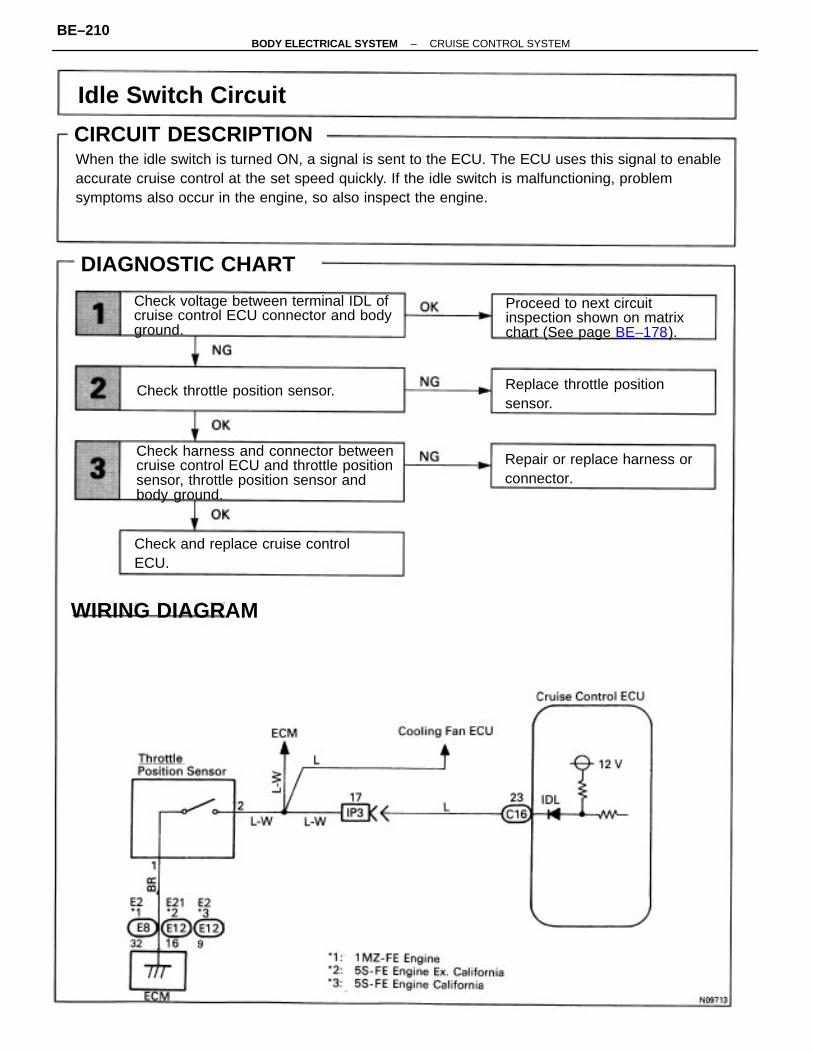
CIRCUIT DESCRIPTIONWhen the idle switch is turned ON, a signal is sent to the ECU. The ECU uses this signal to enableaccurate cruise control at the set speed quickly. If the idle switch is malfunctioning, problemsymptoms also occur in the engine, so also inspect the engine.
Check harness and connector betweencruise control ECU and throttle positionsensor, throttle position sensor andbody ground.
Check voltage between terminal IDL ofcruise control ECU connector and bodyground.
Proceed to next circuitinspection shown on matrixchart (See page BE–178).
Repair or replace harness orconnector.
Replace throttle positionsensor.
Check and replace cruise controlECU.
Idle Switch Circuit
Check throttle position sensor.
DIAGNOSTIC CHART
WIRING DIAGRAM
CIRCUIT DESCRIPTION
–BODY ELECTRICAL SYSTEM CRUISE CONTROL SYSTEMBE–210
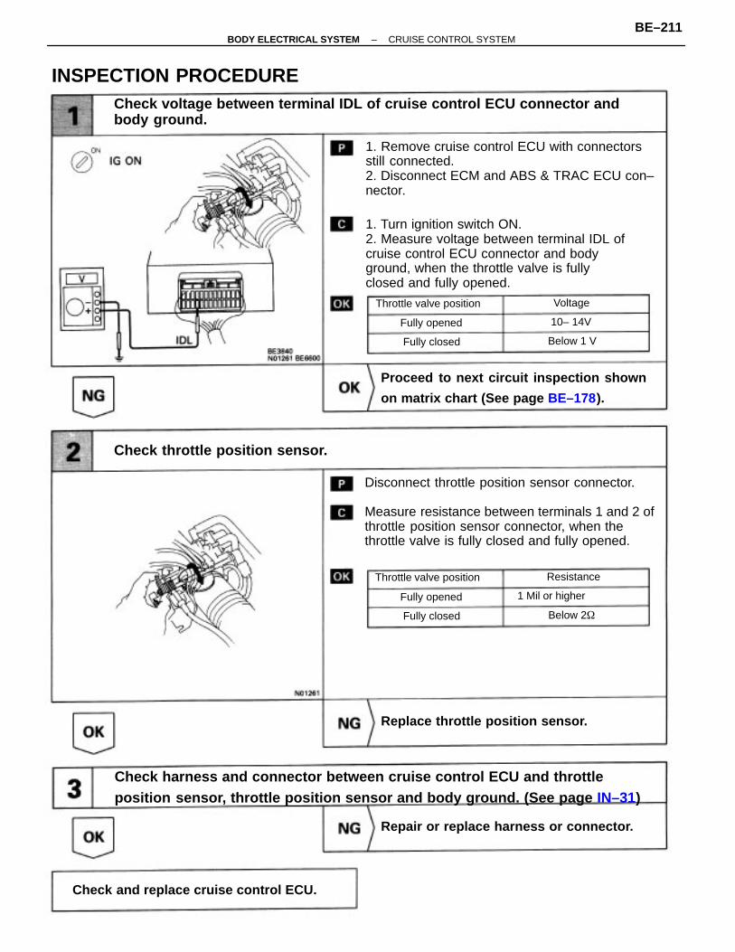
1. Remove cruise control ECU with connectorsstill connected.2. Disconnect ECM and ABS & TRAC ECU con–nector.
1. Turn ignition switch ON.2. Measure voltage between terminal IDL ofcruise control ECU connector and bodyground, when the throttle valve is fullyclosed and fully opened.
Check harness and connector between cruise control ECU and throttleposition sensor, throttle position sensor and body ground. (See page IN–31)
Disconnect throttle position sensor connector.
Measure resistance between terminals 1 and 2 ofthrottle position sensor connector, when thethrottle valve is fully closed and fully opened.
Check voltage between terminal IDL of cruise control ECU connector andbody ground.
Proceed to next circuit inspection shown
on matrix chart (See page BE–178).
Check throttle position sensor.
Check and replace cruise control ECU.
Repair or replace harness or connector.
Replace throttle position sensor.
INSPECTION PROCEDURE
Throttle valve position
Throttle valve position
1 Mil or higher
Fully opened
Fully opened
Fully closed
Fully closed
Resistance
Below 2
Below 1 V
10– 14V
Voltage
–BODY ELECTRICAL SYSTEM CRUISE CONTROL SYSTEMBE–211
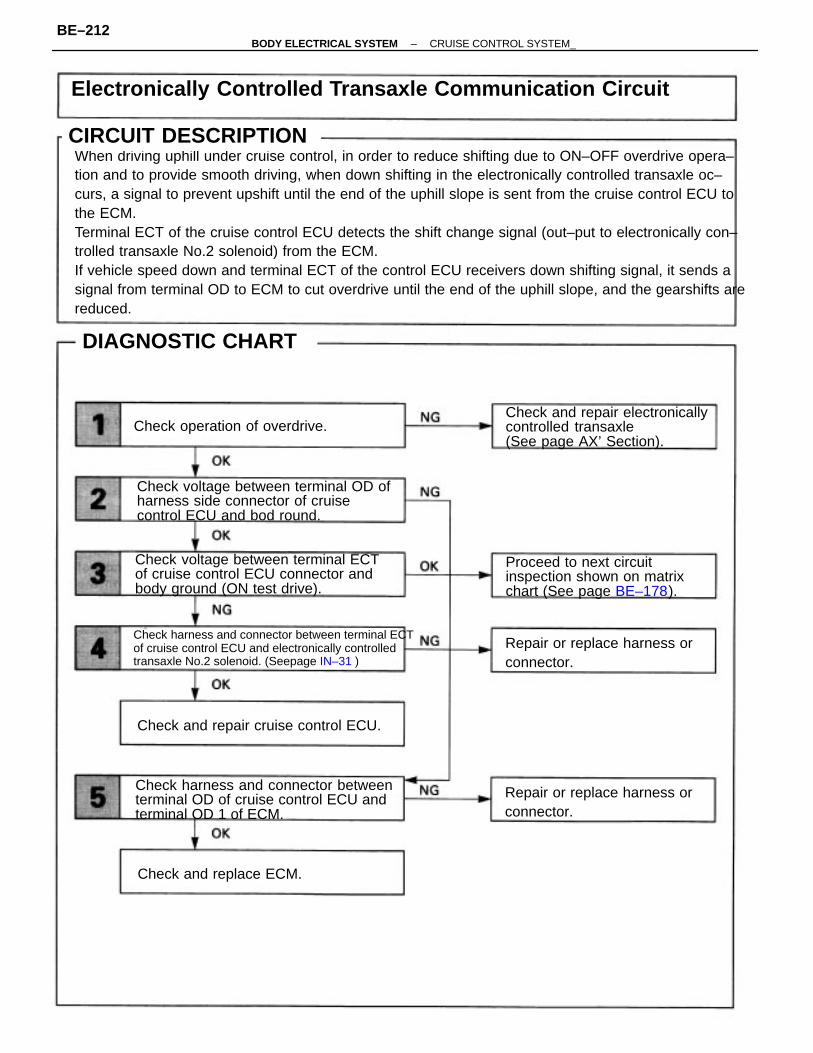
CIRCUIT DESCRIPTIONWhen driving uphill under cruise control, in order to reduce shifting due to ON–OFF overdrive opera–tion and to provide smooth driving, when down shifting in the electronically controlled transaxle oc–curs, a signal to prevent upshift until the end of the uphill slope is sent from the cruise control ECU tothe ECM.Terminal ECT of the cruise control ECU detects the shift change signal (out–put to electronically con–trolled transaxle No.2 solenoid) from the ECM.If vehicle speed down and terminal ECT of the control ECU receivers down shifting signal, it sends asignal from terminal OD to ECM to cut overdrive until the end of the uphill slope, and the gearshifts arereduced.
Electronically Controlled Transaxle Communication Circuit
Check harness and connector between terminal ECTof cruise control ECU and electronically controlledtransaxle No.2 solenoid. (Seepage IN–31 )
Check voltage between terminal ECTof cruise control ECU connector andbody ground (ON test drive).
Check voltage between terminal OD ofharness side connector of cruisecontrol ECU and bod round.
Check harness and connector betweenterminal OD of cruise control ECU andterminal OD 1 of ECM.
Check and repair electronicallycontrolled transaxle(See page AX’ Section).
Proceed to next circuitinspection shown on matrixchart (See page BE–178).
Repair or replace harness orconnector.
Repair or replace harness orconnector.
Check and repair cruise control ECU.
Check operation of overdrive.
Check and replace ECM.
CIRCUIT DESCRIPTION
DIAGNOSTIC CHART
–BODY ELECTRICAL SYSTEM CRUISE CONTROL SYSTEM_BE–212
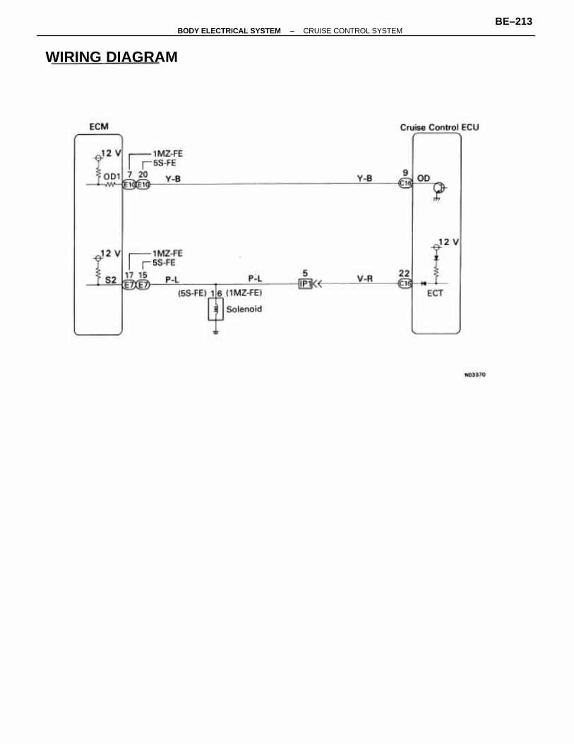
WIRING DIAGRAM
–BODY ELECTRICAL SYSTEM CRUISE CONTROL SYSTEMBE–213
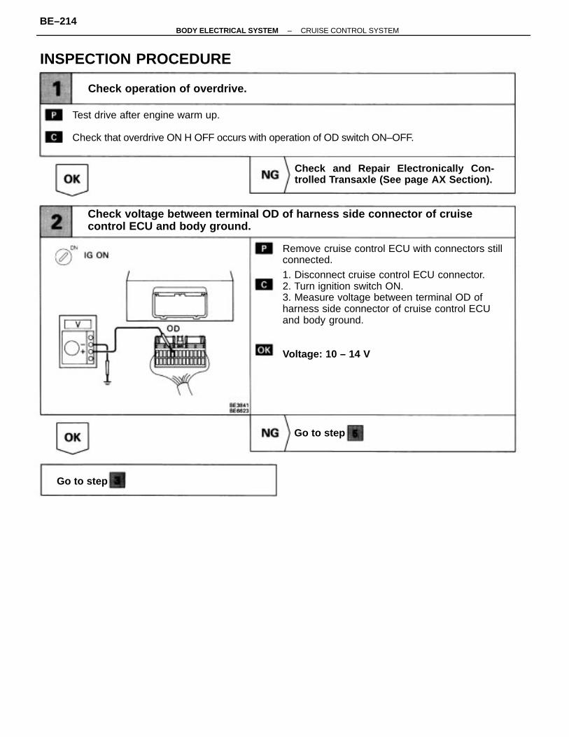
Remove cruise control ECU with connectors stillconnected.
1. Disconnect cruise control ECU connector.2. Turn ignition switch ON.3. Measure voltage between terminal OD ofharness side connector of cruise control ECUand body ground.
Voltage: 10 – 14 V
Test drive after engine warm up.
Check that overdrive ON H OFF occurs with operation of OD switch ON–OFF.
Check voltage between terminal OD of harness side connector of cruisecontrol ECU and body ground.
Check and Repair Electronically Con-trolled Transaxle (See page AX Section).
Check operation of overdrive.
INSPECTION PROCEDURE
Go to step
Go to step
–BODY ELECTRICAL SYSTEM CRUISE CONTROL SYSTEMBE–214
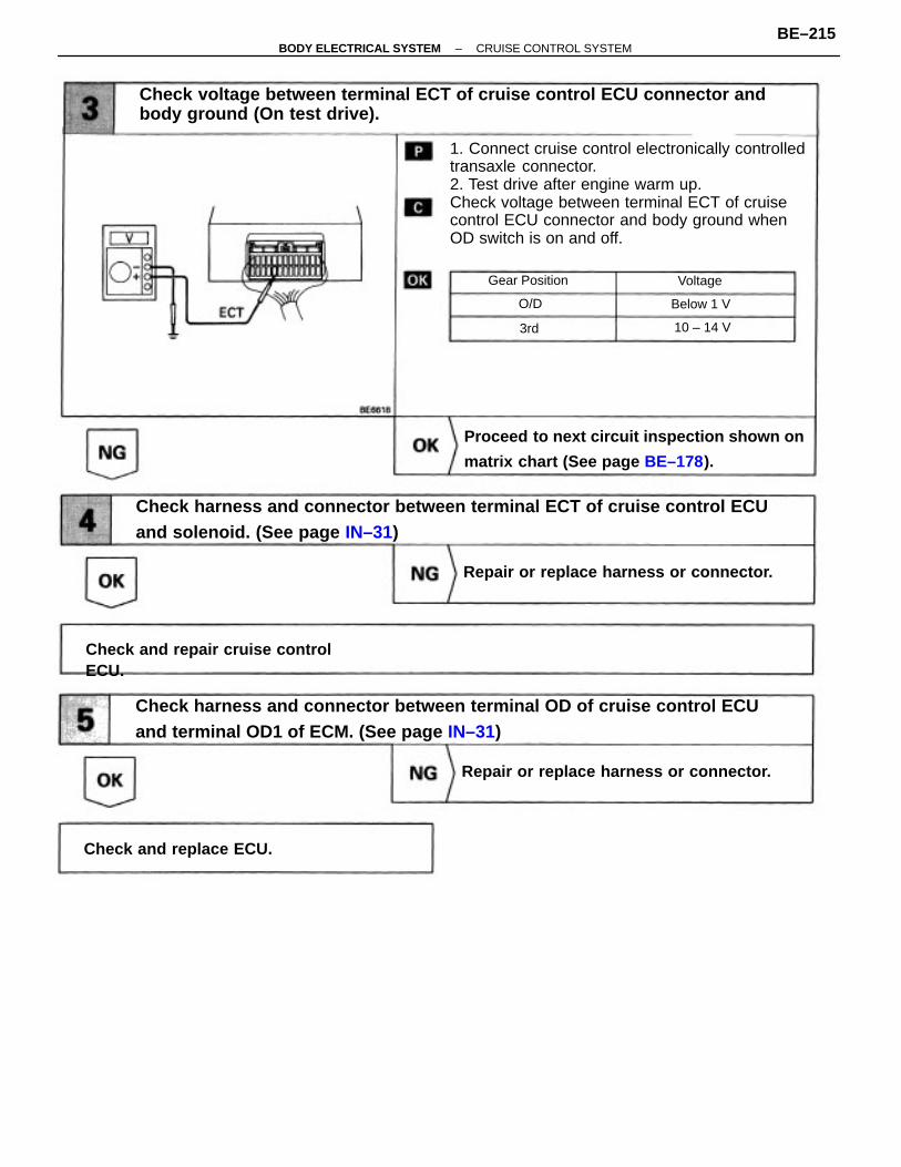
1. Connect cruise control electronically controlledtransaxle connector.2. Test drive after engine warm up.Check voltage between terminal ECT of cruisecontrol ECU connector and body ground whenOD switch is on and off.
Check voltage between terminal ECT of cruise control ECU connector andbody ground (On test drive).
Check harness and connector between terminal ECT of cruise control ECUand solenoid. (See page IN–31)
Check harness and connector between terminal OD of cruise control ECUand terminal OD1 of ECM. (See page IN–31)
Proceed to next circuit inspection shown on
matrix chart (See page BE–178).
Repair or replace harness or connector.
Repair or replace harness or connector.
Check and repair cruise controlECU.
Check and replace ECU.
Gear Position
Below 1 V
10 – 14 V
Voltage
O/D
3rd
–BODY ELECTRICAL SYSTEM CRUISE CONTROL SYSTEMBE–215
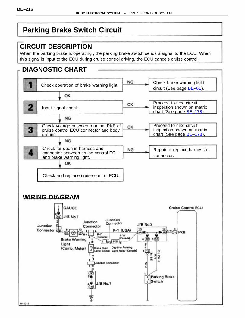
CIRCUIT DESCRIPTIONWhen the parking brake is operating , the parking brake switch sends a signal to the ECU. Whenthis signal is input to the ECU during cruise control driving, the ECU cancels cruise control.
Check voltage between terminal PKB ofcruise control ECU connector and bodyground.
Check for open in harness andconnector between cruise control ECUand brake warning light.
Parking Brake Switch Circuit
Proceed to next circuitinspection shown on matrixchart (See page BE–178).
Proceed to next circuitinspection shown on matrixchart (See page BE–178).
Repair or replace harness orconnector.
Check brake warning lightcircuit (See page BE–61).
Check operation of brake warning light.
Check and replace cruise control ECU.
DIAGNOSTIC CHART
WIRING DIAGRAM
Input signal check.
DIAGNOSTIC CHART
–BODY ELECTRICAL SYSTEM CRUISE CONTROL SYSTEMBE–216
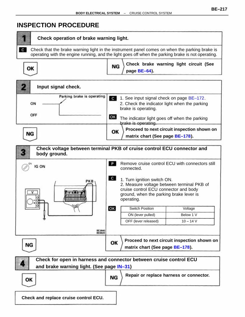
Remove cruise control ECU with connectors stillconnected.
1. Turn ignition switch ON.2. Measure voltage between terminal PKB ofcruise control ECU connector and bodyground, when the parking brake lever isoperating.
1. See input signal check on page BE–172.2. Check the indicator light when the parkingbrake is operating.
The indicator light goes off when the parkingbrake is operating.
Check that the brake warning light in the instrument panel comes on when the parking brake isoperating with the engine running, and the light goes off when the parking brake is not operating.
Check for open in harness and connector between cruise control ECUand brake warning light. (See page IN–31)
Check voltage between terminal PKB of cruise control ECU connector andbody ground.
Proceed to next circuit inspection shown on
matrix chart (See page BE–178).
Proceed to next circuit inspection shown on
matrix chart (See page BE–178).
Check brake warning light circuit (See
page BE–64).
Check operation of brake warning light.
Repair or replace harness or connector.
Check and replace cruise control ECU.
INSPECTION PROCEDURE
Input signal check.
OFF (lever released)
ON (lever pulled)
Switch Position
Below 1 V
10 – 14 V
Voltage
–BODY ELECTRICAL SYSTEM CRUISE CONTROL SYSTEMBE–217
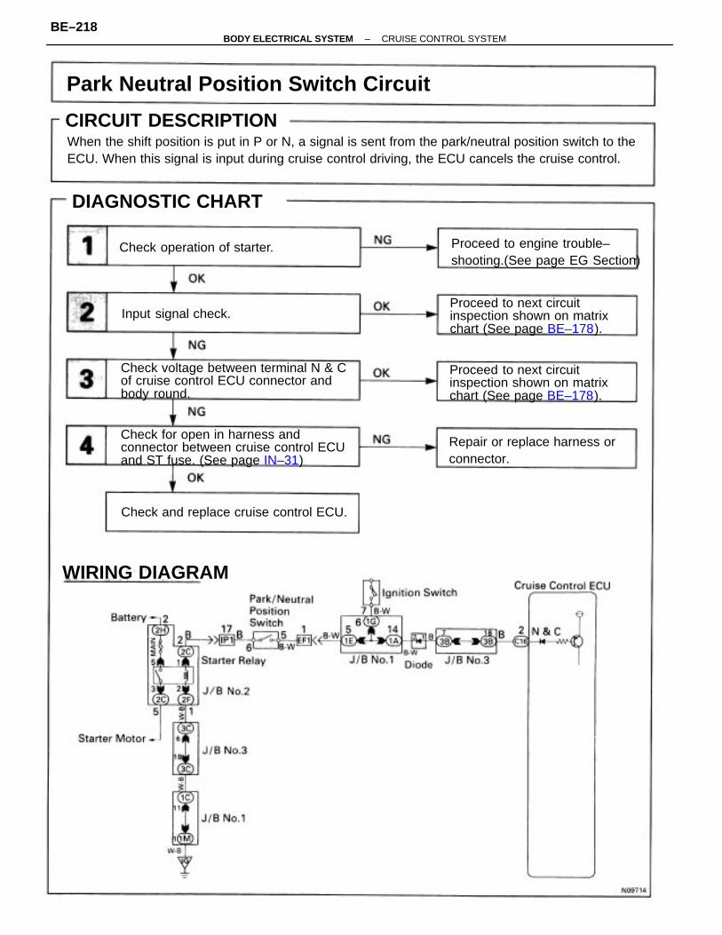
CIRCUIT DESCRIPTIONWhen the shift position is put in P or N, a signal is sent from the park/neutral position switch to theECU. When this signal is input during cruise control driving, the ECU cancels the cruise control.
Check voltage between terminal N & Cof cruise control ECU connector andbody round.
Check for open in harness andconnector between cruise control ECUand ST fuse. (See page IN–31)
Park Neutral Position Switch Circuit
Proceed to next circuitinspection shown on matrixchart (See page BE–178).
Proceed to next circuitinspection shown on matrixchart (See page BE–178).
Proceed to engine trouble–shooting.(See page EG Section)
Repair or replace harness orconnector.
Check and replace cruise control ECU.
DIAGNOSTIC CHART
Check operation of starter.
WIRING DIAGRAM
Input signal check.
CIRCUIT DESCRIPTION
–BODY ELECTRICAL SYSTEM CRUISE CONTROL SYSTEMBE–218
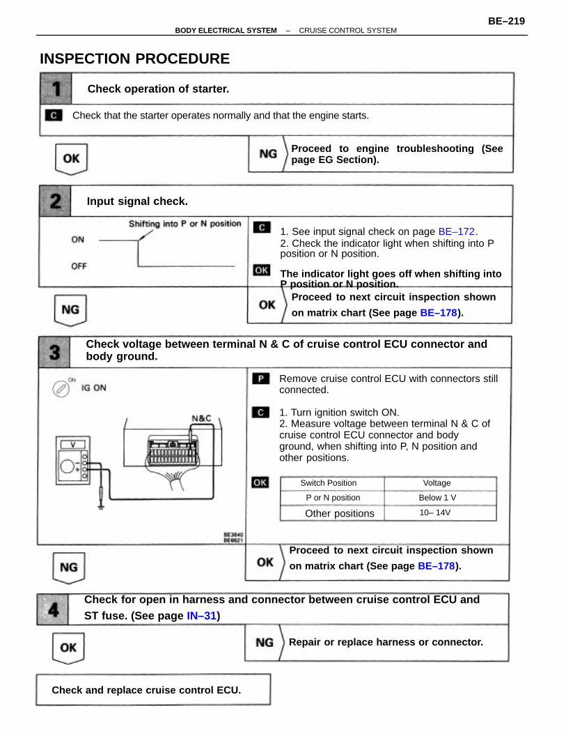
Remove cruise control ECU with connectors stillconnected.
1. Turn ignition switch ON.2. Measure voltage between terminal N & C ofcruise control ECU connector and bodyground, when shifting into P, N position andother positions.
1. See input signal check on page BE–172.2. Check the indicator light when shifting into Pposition or N position.
The indicator light goes off when shifting intoP position or N position.
Check for open in harness and connector between cruise control ECU andST fuse. (See page IN–31)
Check voltage between terminal N & C of cruise control ECU connector andbody ground.
Proceed to next circuit inspection shown
on matrix chart (See page BE–178).
Proceed to next circuit inspection shown
on matrix chart (See page BE–178).
Proceed to engine troubleshooting (Seepage EG Section).
Check that the starter operates normally and that the engine starts.
Repair or replace harness or connector.
Check and replace cruise control ECU.
Check operation of starter.
INSPECTION PROCEDURE
Input signal check.
Other positions
P or N position
Switch Position
Below 1 V
10– 14V
Voltage
–BODY ELECTRICAL SYSTEM CRUISE CONTROL SYSTEMBE–219
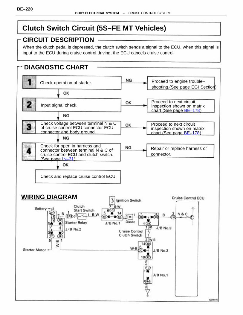
CIRCUIT DESCRIPTIONWhen the clutch pedal is depressed, the clutch switch sends a signal to the ECU, when this signal isinput to the ECU during cruise control driving, the ECU cancels cruise control.
Clutch Switch Circuit (5S–FE MT Vehicles)
Check for open in harness andconnector between terminal N & C ofcruise control ECU and clutch switch.(See page IN–31)
Check voltage between terminal N & Cof cruise control ECU connector ECUconnector and body ground.
Proceed to next circuitinspection shown on matrixchart (See page BE–178).
Proceed to next circuitinspection shown on matrixchart (See page BE–178).
Proceed to engine trouble–shooting.(See page EGI Section)
Repair or replace harness orconnector.
Check and replace cruise control ECU.
DIAGNOSTIC CHART
Check operation of starter.
WIRING DIAGRAM
Input signal check.
CIRCUIT DESCRIPTION
–BODY ELECTRICAL SYSTEM CRUISE CONTROL SYSTEMBE–220
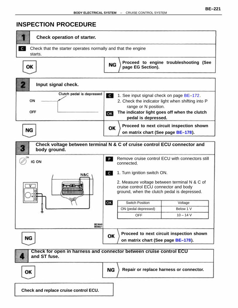
Remove cruise control ECU with connectors stillconnected.
1. Turn ignition switch ON.
2. Measure voltage between terminal N & C ofcruise control ECU connector and bodyground, when the clutch pedal is depressed.
1. See input signal check on page BE–172.2. Check the indicator light when shifting into P
range or N position.The indicator light goes off when the clutch
pedal is depressed.
Check for open in harness and connector between cruise control ECUand ST fuse.
Check voltage between terminal N & C of cruise control ECU connector andbody ground.
Proceed to next circuit inspection shown
on matrix chart (See page BE–178).
Proceed to engine troubleshooting (Seepage EG Section).
Proceed to next circuit inspection shown
on matrix chart (See page BE–178).
Check that the starter operates normally and that the enginestarts.
Repair or replace harness or connector.
Check and replace cruise control ECU.
Check operation of starter.
INSPECTION PROCEDURE
Input signal check.
ON (pedal depressed)
Switch Position
Below 1 V
10 – 14 V
Voltage
OFF
–BODY ELECTRICAL SYSTEM CRUISE CONTROL SYSTEMBE–221
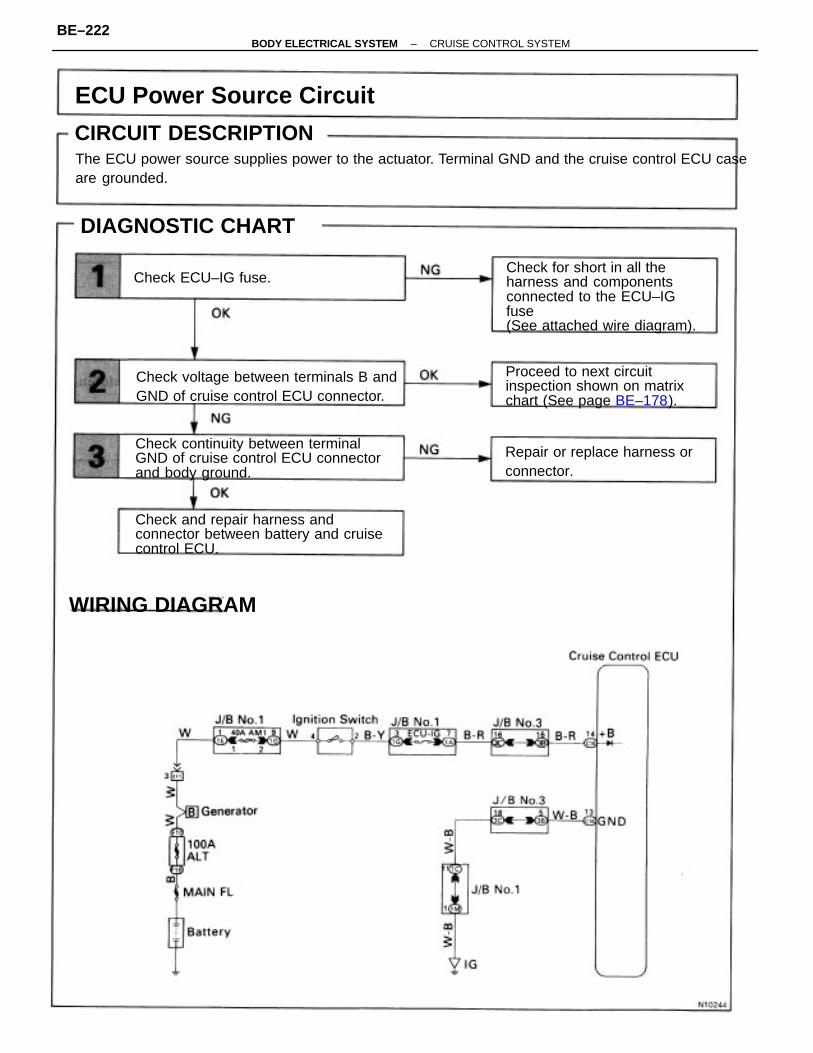
CIRCUIT DESCRIPTIONThe ECU power source supplies power to the actuator. Terminal GND and the cruise control ECU caseare grounded.
Check for short in all theharness and componentsconnected to the ECU–IGfuse(See attached wire diagram).
Check continuity between terminalGND of cruise control ECU connectorand body ground.
Check and repair harness andconnector between battery and cruisecontrol ECU.
Check voltage between terminals B andGND of cruise control ECU connector.
Proceed to next circuitinspection shown on matrixchart (See page BE–178).
ECU Power Source Circuit
Repair or replace harness orconnector.
DIAGNOSTIC CHART
WIRING DIAGRAM
Check ECU–IG fuse.
CIRCUIT DESCRIPTION
–BODY ELECTRICAL SYSTEM CRUISE CONTROL SYSTEMBE–222
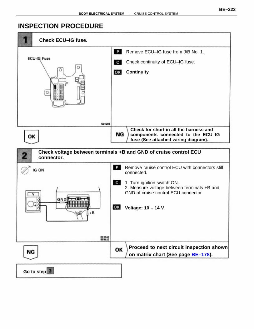
Remove cruise control ECU with connectors stillconnected. 1. Turn ignition switch ON.2. Measure voltage between terminals +B andGND of cruise control ECU connector.
Voltage: 10 – 14 V
Check voltage between terminals +B and GND of cruise control ECUconnector.
Remove ECU–IG fuse from J/B No. 1.
Check continuity of ECU–IG fuse.
Continuity
Check for short in all the harness andcomponents connected to the ECU–IGfuse (See attached wiring diagram).
Proceed to next circuit inspection shownon matrix chart (See page BE–178).
INSPECTION PROCEDURE
Check ECU–IG fuse.
Go to step
–BODY ELECTRICAL SYSTEM CRUISE CONTROL SYSTEMBE–223
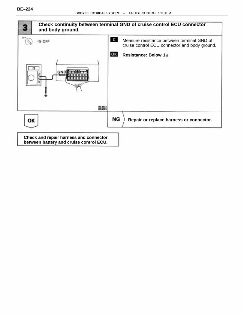
Check continuity between terminal GND of cruise control ECU connectorand body ground.
Measure resistance between terminal GND ofcruise control ECU connector and body ground.
Resistance: Below 1
Check and repair harness and connectorbetween battery and cruise control ECU.
Repair or replace harness or connector.
–BODY ELECTRICAL SYSTEM CRUISE CONTROL SYSTEMBE–224

– MEMO –
–BODY ELECTRICAL SYSTEM CRUISE CONTROL SYSTEMBE–225
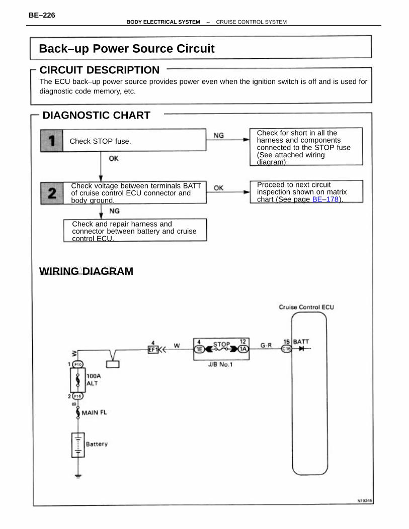
CIRCUIT DESCRIPTIONThe ECU back–up power source provides power even when the ignition switch is off and is used fordiagnostic code memory, etc.
Check for short in all theharness and componentsconnected to the STOP fuse(See attached wiringdiagram).
Check voltage between terminals BATTof cruise control ECU connector andbody ground.
Check and repair harness andconnector between battery and cruisecontrol ECU.
Back–up Power Source Circuit
Proceed to next circuitinspection shown on matrixchart (See page BE–178).
DIAGNOSTIC CHART
WIRING DIAGRAM
Check STOP fuse.
CIRCUIT DESCRIPTION
–BODY ELECTRICAL SYSTEM CRUISE CONTROL SYSTEMBE–226
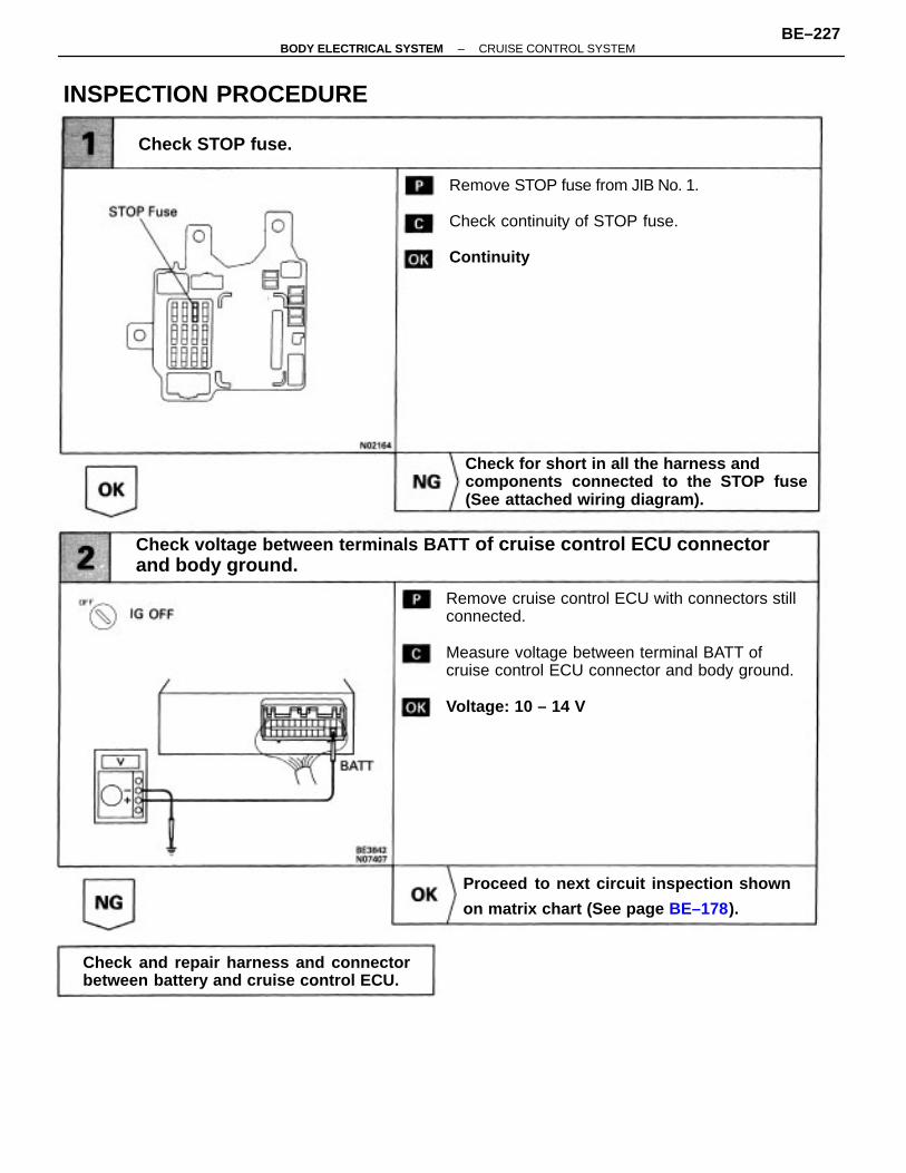
Remove cruise control ECU with connectors stillconnected.
Measure voltage between terminal BATT ofcruise control ECU connector and body ground.
Voltage: 10 – 14 V
Check voltage between terminals BATT of cruise control ECU connectorand body ground.
Remove STOP fuse from JIB No. 1.
Check continuity of STOP fuse.
Continuity
Check for short in all the harness andcomponents connected to the STOP fuse(See attached wiring diagram).
Proceed to next circuit inspection shown
on matrix chart (See page BE–178).
Check and repair harness and connectorbetween battery and cruise control ECU.
INSPECTION PROCEDURE
Check STOP fuse.
–BODY ELECTRICAL SYSTEM CRUISE CONTROL SYSTEMBE–227
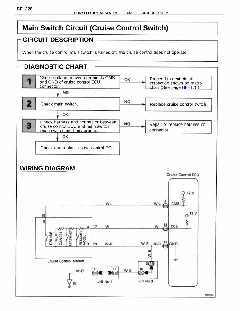
CIRCUIT DESCRIPTION
When the cruise control main switch is turned oft, the cruise control does not operate.
Main Switch Circuit (Cruise Control Switch)
Check harness and connector betweencruise control ECU and main switch,main switch and body ground.
Check voltage between terminals CMSand GND of cruise control ECUconnector.
Proceed to next circuitinspection shown on matrixchart (See page BE–178).
Repair or replace harness orconnector.
Check and replace cruise control ECU.
Replace cruise control switch.
DIAGNOSTIC CHART
Check main switch.
WIRING DIAGRAM
CIRCUIT DESCRIPTION
–BODY ELECTRICAL SYSTEM CRUISE CONTROL SYSTEMBE–228
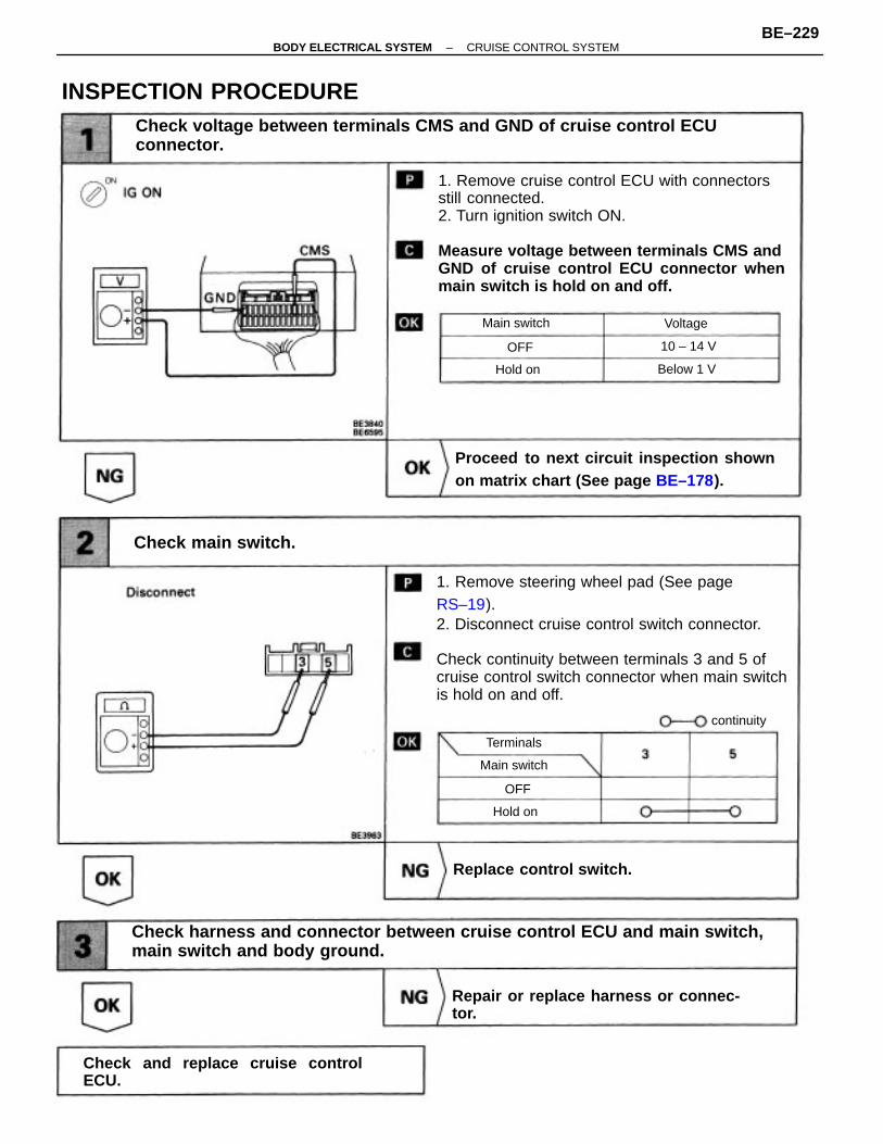
1. Remove steering wheel pad (See pageRS–19).2. Disconnect cruise control switch connector.
Check continuity between terminals 3 and 5 ofcruise control switch connector when main switchis hold on and off.
1. Remove cruise control ECU with connectorsstill connected.2. Turn ignition switch ON.
Measure voltage between terminals CMS andGND of cruise control ECU connector whenmain switch is hold on and off.
Check harness and connector between cruise control ECU and main switch,main switch and body ground.
Check voltage between terminals CMS and GND of cruise control ECUconnector.
Proceed to next circuit inspection shownon matrix chart (See page BE–178).
Repair or replace harness or connec-tor.
Check and replace cruise controlECU.
INSPECTION PROCEDURE
Check main switch.
Replace control switch.
Main switch
Main switch
continuity
Below 1 V
Terminals
10 – 14 V
Voltage
Hold on
Hold on
OFF
OFF
–BODY ELECTRICAL SYSTEM CRUISE CONTROL SYSTEMBE–229
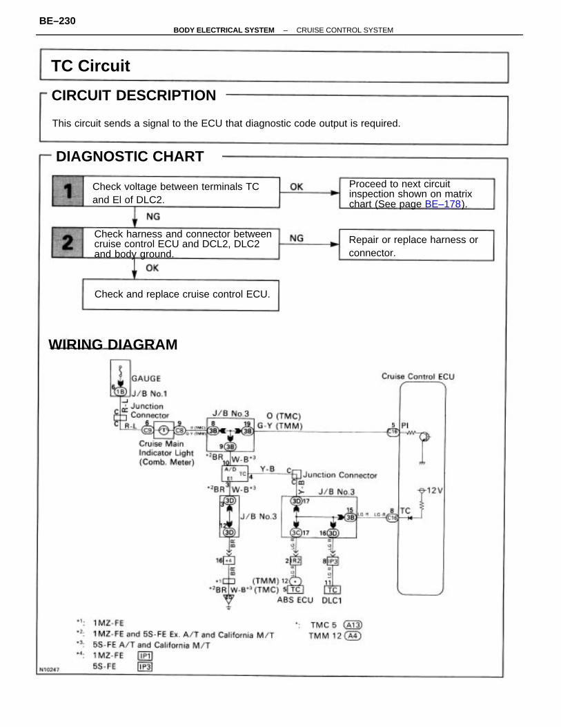
CIRCUIT DESCRIPTION
This circuit sends a signal to the ECU that diagnostic code output is required.
Check harness and connector betweencruise control ECU and DCL2, DLC2and body ground.
Check voltage between terminals TCand El of DLC2.
Proceed to next circuitinspection shown on matrixchart (See page BE–178).
Repair or replace harness orconnector.
Check and replace cruise control ECU.
DIAGNOSTIC CHART
WIRING DIAGRAM
TC Circuit
CIRCUIT DESCRIPTION
–BODY ELECTRICAL SYSTEM CRUISE CONTROL SYSTEMBE–230
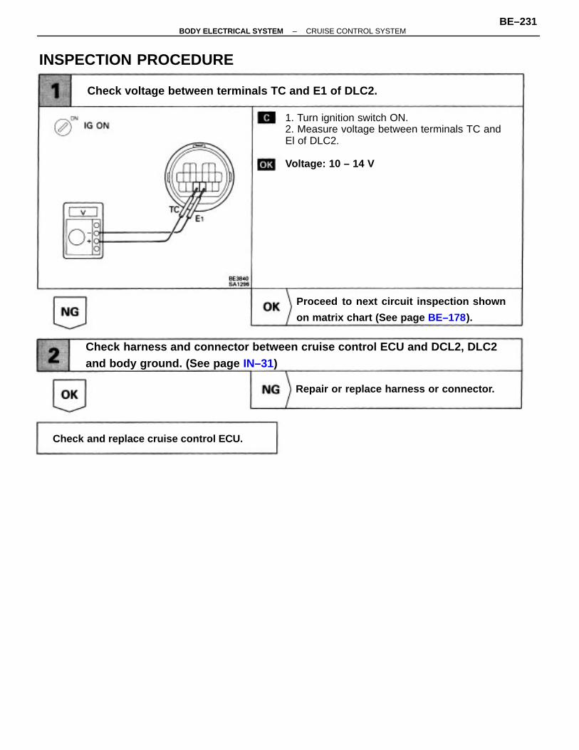
Check harness and connector between cruise control ECU and DCL2, DLC2and body ground. (See page IN–31)
1. Turn ignition switch ON.2. Measure voltage between terminals TC andEl of DLC2.
Voltage: 10 – 14 V
Check voltage between terminals TC and E1 of DLC2.
Proceed to next circuit inspection shown
on matrix chart (See page BE–178).
Repair or replace harness or connector.
Check and replace cruise control ECU.
INSPECTION PROCEDURE
–BODY ELECTRICAL SYSTEM CRUISE CONTROL SYSTEMBE–231
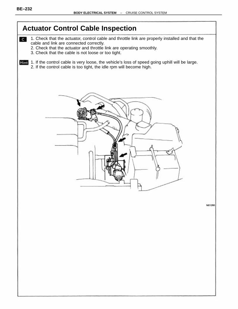
1. Check that the actuator, control cable and throttle link are properly installed and that thecable and link are connected correctly.2. Check that the actuator and throttle link are operating smoothly.3. Check that the cable is not loose or too tight.
1. If the control cable is very loose, the vehicle’s loss of speed going uphill will be large.2. If the control cable is too tight, the idle rpm will become high.
Actuator Control Cable Inspection
–BODY ELECTRICAL SYSTEM CRUISE CONTROL SYSTEMBE–232