Embed Size (px)
Citation preview
•
•
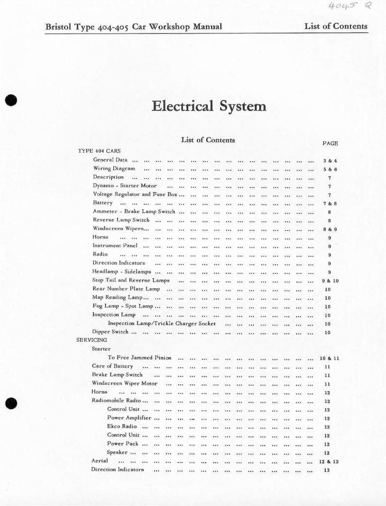
Bristol Type 404-405 Car Workshop Manual
Electrical System
TYPE 404 CARS
General Data
Wiring Diagram
Deacri ption
Dynamo _ Starter Motor
List of Contents
Voltage Regulator and Fuse Box ...
Battery
Ammeter . Brakl!' Lamp Switch.
Reverse Lamp S witch
Wi ndsc ree n Wipe ........
Ho rns
Instrume nt Panel
Radio
Direction Indicators
Headlamp _ Side lamps
S top Tail and Reverse Lamps
Re ar Number Plate Lamp
Map Rellding Lamp ."
Pog Lamp _ Spot Lamp ...
Inspection Lamp
Inspection LamplTrickle Charger Socket
Dippe r Switch
SERVICING
Staru:r
To Fret: Jammed Pinion
Care of Bstlery
Brake Lamp SWitch
Windsc reen Wiper Motor
H orns
Radiomobile Radio _ •.
Control Unit ...
Powe r Amplifier
Ekeo Radio
Control Unit
Power Pack
Speaker •..
Aeria l
Direction IndicatOr..
List of Contents
PAGE
3&4
,. 6
7
7
7
7&8 , ,
,&9
9
9
9
9
9
9 &. 10
10
10
10
10
10
10
10 &. 11
11
11
11
12
12
12
12
12
12
12
12
12 &. 13
13
Bristol Type 404-405 Car Workshop Manual
List of Contents
SERVICING (Cone.)
Direction Indicator Switch
Removing and Refitting InstrumentS
Early Type Cars
Speedometer and Revolution Counter
Oil Temperature Gauge
Waler Temperature Gauge ...
Combined Inan-ument ...
Replacing Bulbs
Ignition and Fuel ReBel've Warning Light
Speedometer and Revolution Coumc<; ..
Illuminating Lamps
Headlamp Warning Lamp .. .
Oil and Water Temperature and
Combined Instrument Illumination Lamp"
Removing and Refining ImHrumcnts
Later Type Cars
Speedometer ...
Revolution Counter
Oil Pressure Gauge
Oil Temperature Gauge
Water Temperature Gauge
Fuel Gauge
Ammeter
Replacing Bulbs
Fuel and Ignition Warning Lights.
Speedometer and Revolution Counter
Direction IndicafOr Warning Lamp ..•
Oil and Water Temperature, Oil Prellllur e
Fuel and Ammeter Illuminating Lamps
Headlamp"
Sett!ng the Beam
Side Lamps ...
Stop Tail and Reverse Lamps
Rear Number Plate Lamp ...
Direction Indicators
Map Reading Lamp. Interior Lamp
Spot Lamp and Fog Lamp ...
Adjusting the Beams .•.
TYPE 405 CARS
General Data ...
Wiring Diagram
Description
Dynamo
List of Contents
PAGE
13
13
13
13
13
13
13
13
13
13
14
14
H
14
14
14
14
14
14
14
14
14 &. 15
15
15
15
15
15
15
15 &. 16
16
17 &. 18
19 &. 20
21
21
•
•
•
•
Bristol Type 404-405 Car Workshop Manual
List of Contents
T YPE 405 CARS (Cont.)
St·arter Motor ...
Voltage Regulator and Fuse Box ...
Batte r y
Ammeter
Brake Lamp Switch
Reverse Lamp Switch
Overdrive Switch (Gearbox Operated)
Windsc reen Wipers ...
Horns
Instrument Panel
Radio
Flashers
Headlamp"
Sidelamps ...
Stop r e ar and Direction Lamps and Reflec tors
Map Reading Lamp ...
Fog Lamp .. .
Spot Lamp .. .
Inspection Lamp
Inspection Lamp/Trickle Charger Socket
Dipper Switch ...
Boot Lamp ..
Warning Lamps
Ignition Warning Lamp
Headlamp Warning Lamp
F ue l Warning Lamp
Direction Indic ator Warning Lamp
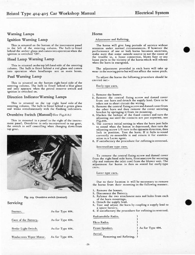
Overdrive Switch (Manual)
SERVICING
S tarter, Care of Battery, Brake L ight Switch and Windscreen Wiper Motor (As ror Type 404)
Horns
Radiomobilc Radio
Ekco Radio
Front Speaker
Ae rial
As for Type 404
List of Contents
PAGE
21
21
21
21
2 1
21
22
22
22
22
22
22
22
23
23
23
23
23
23
23
23
23
" " 24
24
24
24
•
•
Bristol Type 404-405 Car Workshop Manual
Electrical System
~"'tS q
Electrical System
•
•
Bristol Type 404-405 Car Workshop Manual Electrical System
Electrical System
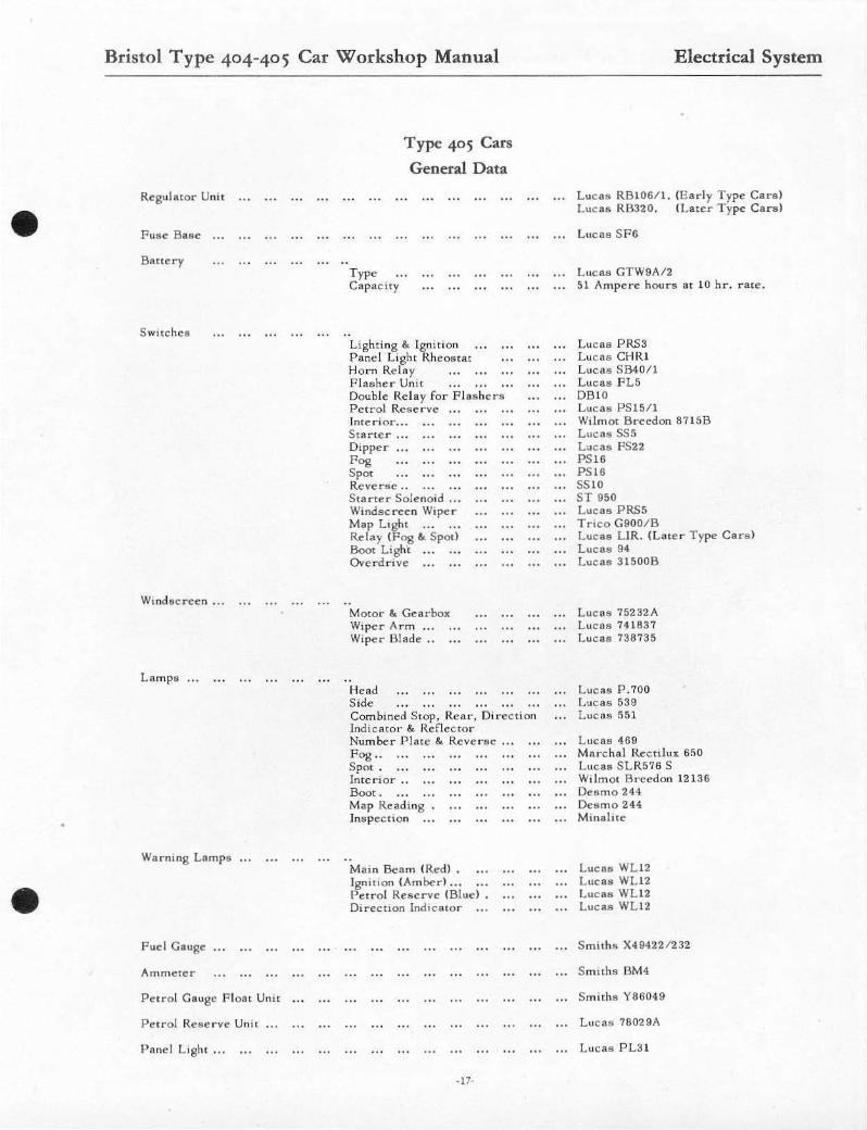
Regulator Unit
F use Baae
Banery
S Wi tches
Wind screen Wiper Motor
Type Capacity
Type 404 Cars
General Data
Lighting &. Ignition Lighting .. Ignition Pane l Lig ht &. Rheos tat Hor n Relay .... " Direction Ind iclllOr S tarter Dippel'" ••• Fog .. Spot .. Petrol Reserve Starter Solenoid ... Windscreen Wiper Map Light Reverse Light Interior ...
Wiper Arm Wiper Blade ...
Combined Instruments (early type c ars )
Radio (special order a lternal1ve)
Fuel Gaug., Oi l Preflflure Gauge Ammeler Fuel Gauge (l ate r type eo r s) Ammerer (lal., r Iype ca r s) Petro l Gauge Flo~1I Unil
Pel r o l Refle r ve Un u ...
Early type c ars HMY HMV (ove r seas) ... E keo
Laler Iype cars HMY ... , HMV (over8eBfI) ... E keo
.J.
12 volt Positive Earth Retur n
Luc!III RF95/2 (Early Type Cars ) Lucas RB10611 ( Later Type Cars)
Lucu SP6 (Lalc r T ype Cars)
L UC88 GTW9A12 51 Ampere houn. a l 10 hr. rate
Lue as P LC6 (Ea rl y Type Ca rs) Lucas PRS3 (Late r T ype Ca rs) Luess CH IH Lucas SB4 01l Lucas TS l Lues ... SSs Luess FS22 LueR'" PS I6 LucRa PS I S Lucss PSI5/1 Lues ... ST950 Luesa PRS5 Tri co G900/B SS IO Smiths 64811
Luese 75232/\
Luess 745072 Luese 738735
S nl ith", X5 6007l3 1
Smitha X494221227 S miths BM4 S m ith", EXY 12667 (Early T ype Ca NI) S miths YB0882/ 1 (Lster T ype Ca r s) Luese 78028A
Mco::Icl 4260 Model 4262 Type CH. 152
Type 200X Type 202X Type eR 152
Bristol Type 404-405 Car Workshop Manual
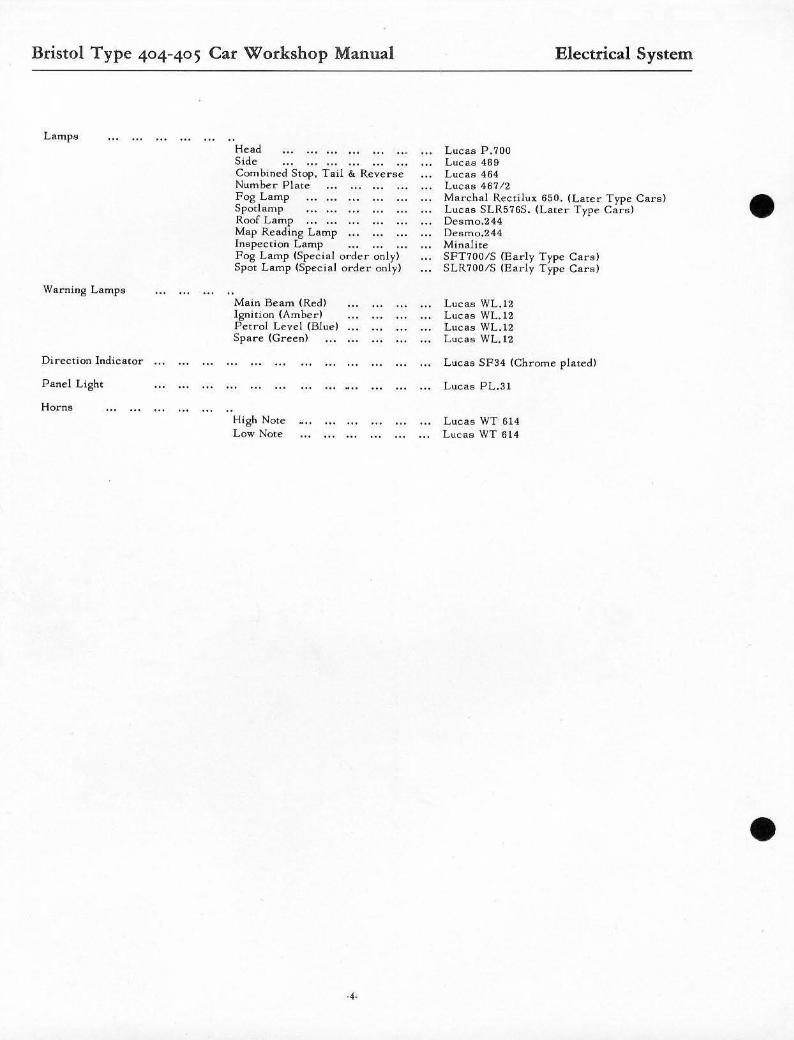
Lamps
Warning Lamps
Direction Indicato r
Panel Light
Horns
Head .. , •..... Side ........ . Com bined Stop, Tail &. Reverse Number Plate Fog Lamp Spotlamp Roof Lamp Map Reading Lamp Inspec tion Lamp Fog Lamp (Special order only) Spot Lamp (Specia l order only)
Main Be am (Red) Ignition (Amber! Petrol Level (Blue) Spare (Green)
High Note Low Note
Luea!'! P.700 Luc9a 469 LUC8S 464 Lucas 46712
Electrical System
Marchal Recti lux 650. (Later Type Car s ) Luess SLR5765 . (Later Type Cars) Deamo.244 Desmo.244 Minalite SFT700/S (Early Type Cars) SLR700/$ !Early Type Cars)
Luess WL.12 Lues!! WL.12 Lucas WL.12 Luess WL.12
Lucaa SF34 (Chrome plated)
Luess Pt.3l
Lues!! WT 61 4 LUCRS WT 614
•
•
•
•
, -,
SN.6.P CO NN F.CTO RS
~
TO FOG lAMP
, ,
STARTER
REGULATOR
STA RTE R
WI"' : TO'N£ 1,' "'re i kl HORNS
RELAY
'0'
'8 18
'CJ
I I -
I -, 1
1 B ATTERY
""'''"'0' (~ o~)\iJ----------, ,-""- ' T I Will
cl IGN . AI COIL I
,--=-Ij DYN"MO
TO SPOT
Ig:
WI PER SW ITCIl
,, ' ,I ,
~ I
PA NEL _I ' \ .
RH EOS TAT~I
\ REVOLUTION M"''' ,
S WI TC H
SPOT lAMP SW ITCH
RIGHT fl ... NO TRAFFICATOR ,
1~~~IIS ING SWITC H
co, '-'
1,'< \ , J
\ ~p: \
I S WI TC H
~3§=+m:l+~'~ "'-"'1 PETROL TAN~ rfo.;-t---'
I GN I TION I L- I ~N~~S~ ' \ : I (/11-,
/
I If I'-- ~
I I
LEFT HAND '~~~ TRAFFICA TO R ~ ,
, ,
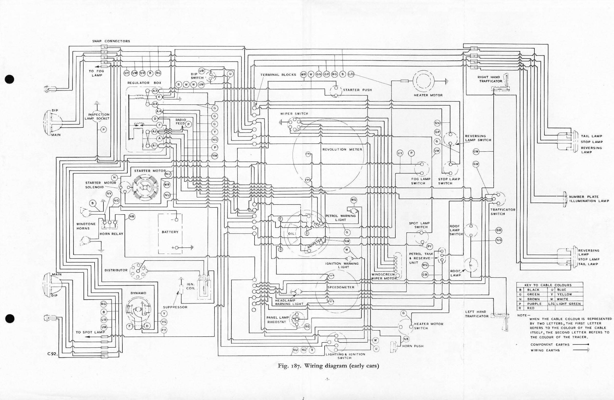
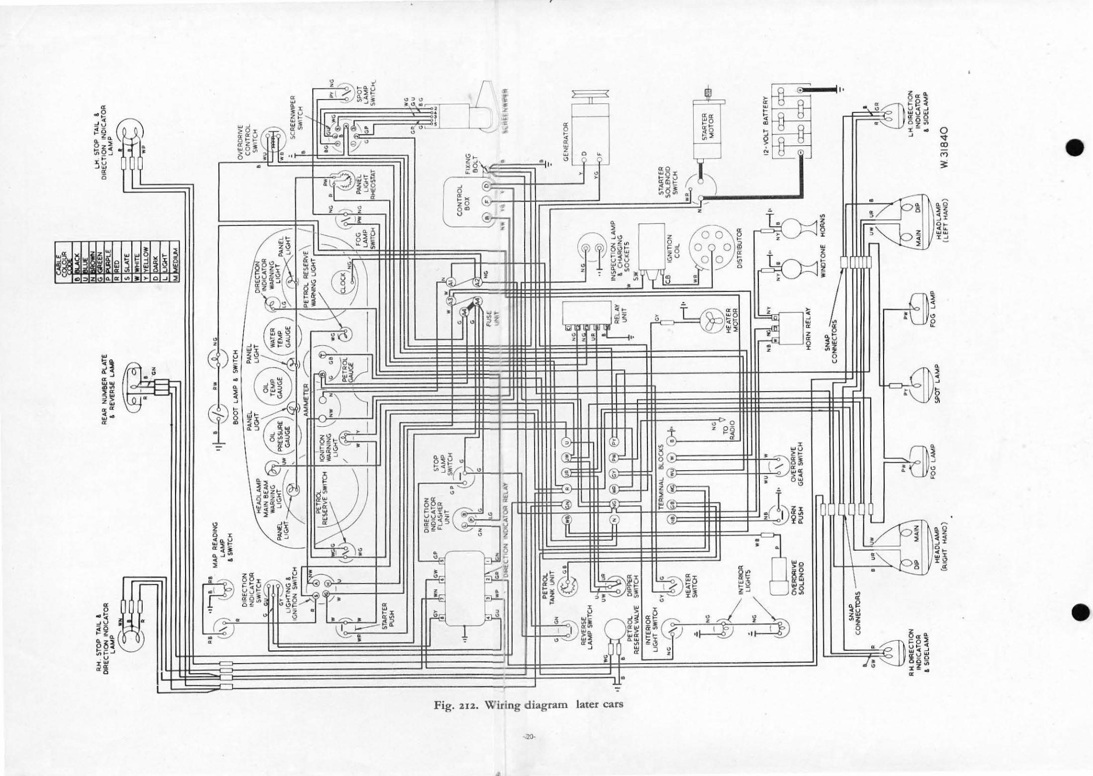
Fig. 187' \Viring diagram (early cars)
I
ND1E-
TI'.IL L .6.'" , , 11,
S TOP lAM , -4lJ REVERS I N " LAMP
L ___ ,_-+ I NUMBER PLA,TE
L-----t' &' ILL UMINATIO N L .o.MP
-, I LA,MP
; 11 STOP L AMP
I L AMP
WHEN THE CABLE C OlOUR IS REPRESENTED
IIV TWO LE TT ERS , THE F IRST LETT ER REFERS TO THE COLOUR O F THE C ... llll'.
ITSELF, THE SECOND LETTER REFERS TO
TH E COLOUR OF T HE TRACE R.
CO t,l PONE NT E"IITHS •
Wi lli NG [ "IITHS if
." --". ,
" '" '"
STOP TAll I. REVER!oE LAMP --,
4~ LIGHT I. SWITCH
18 -.".#
17 21'- ,/
LI GHTING ... '., ' -"--N SW! ~
"'-'M8(R PLATE LAMP
-----S~7
:ID ;;:;,. 1 1\ \ I 'ON"'ON 1 n STARTER I "~~ ) I L'\ ln \ WARNING \~"7
jj d 11 1 (I> " A -"-" - ' , A -'
9 '°1 13 PETROL
RESERVE SWITCH
PETROL RESERVE WARNING LIG HT
---Q ,
~0/ FOG L.AMF' SWITCH
STOP TAlL. AEV(lIISf;. L..AtroIIP
.,.I:;'l+.l--
SCREEN WFER
49 ]".01
-----~ .. 1IIII "~ -
lTI1 (RH) TRAFFICATORS t LH I
" 11 , _____ __. 11 I :~ :
[!ill ' FUSE UNIT ,. - --='1 r;;,--'~d II""~'
,121 niB
PETROL
- '-' -.~, ~~ .... SWiTCH
"E~ [0,
::E
lrANK~ I11 I§~~W\R fl SE LAMP 24 llll I I J L
SWITCH rr=:: -
11 '11'
" I s== INSPECTION • CHARGING SO,
38 ~'O'--"
·'1 . © '-"-
~ SCRH N
~ GENERATOR
J/~
11 ~' • 2 L.H ~ d: r 3 ~IOl I66 S3 @: ., 57 \:: 49 :::t I, .... PETROL DIPP ER I sw COIL
-Jg RE SERVE ... .'.LYE SWITCH 9 ~ _
. 0. 66 ~~ STARTER STARTER ~ - , OC , '"-;: ~ SOLENOID _ __ ~ " 11? I~TE~~~Al SL K r SwtTCH -", ~ 13) ~'1 \..y@ 16
" 'I 1 I~' '9 ! Lzt, tJ . - " /'" 0':" ~ ~" - A 0 0 IJ n tmRIOR (b0 49 \ 0 0 ~ s~~~ 0..1) TO HUTER " 0 / S RADIO MOTOR OISTRIBlfTOA
~ -38 0 3 35 12 VOLT BATTERY
INTERIOR (.h61 (b\ fii:' 66 " . 6 , 351 rsr' 35 1157" r:-= ----, LIGHT '-V \.::::r' \:f):L r-r LZ' ( 10:::0 a=o a:o I
HEATER (
'W''''H 'Ho," j( - = " " l ~.,
, I
,
, t1::
•
IS7t
-l.. .. Lt -UJ:
"J; \ C"'L------, "
C'" ~ ""
FOG LAMP
REI-.... V ~ ..::.. 1':::.. _ I WINDTONE HORNS
h ~ I ,I :::c 5'.]; \ " ~
/.'d'N ~ SPOTLAMP
" c:b FOG LAMP
LH. HEADLAMP
-
(
KEY TO CABLE COLOUR 5
~ ,
f. ~ ,
~ ~ ~ ~ , :gHP "
'~'~ " WN iiii = in ~ :i: WH Wllli Y
:= ~ ~ ,
~ " WI TH Y W .. BLACK WITH 8
C711
•
='
•
•
Bristol Type 404-405 Car Workshop Manual Electrical System
Type 404 Cars
Description
The 12 volt electrical system IS a single wit,,, type c it'cuit having the positive (+) pole of the battery earthing to rh" engine and car. Cllrrcot is sllppliedby a two brush dynamo in conjunction with a voltage regulator and 00
~utornatic c ur out. Two 35 amp fuse s an: fined in the acccssoric" circuit.
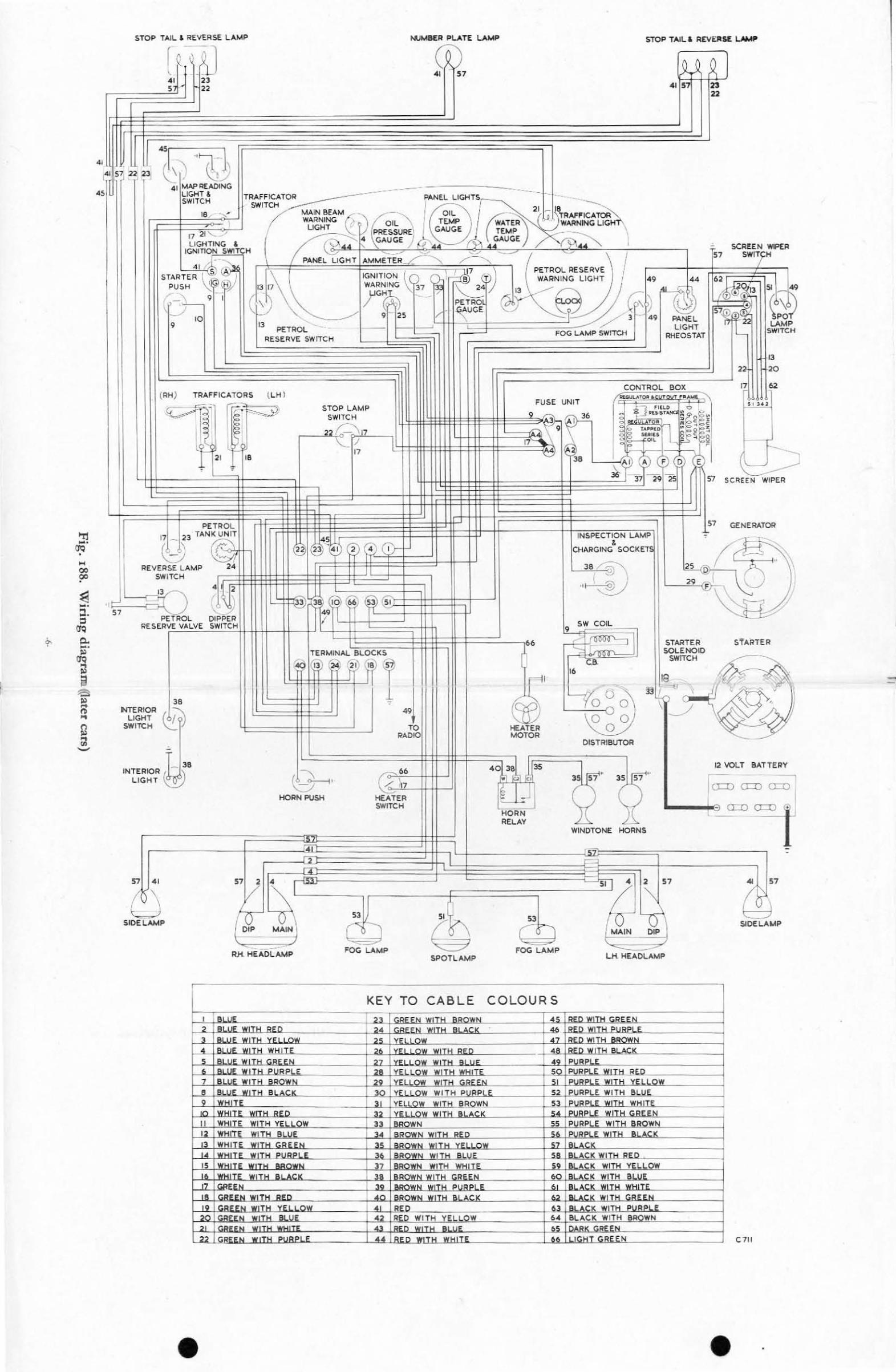
Wiring Diagram karly type can;). Fig.187. Wi"ing Diagram (later type cars). Fig.18B.
Dynamo
The dynamo is belt driven and is mounted in 11 swivcl~ ling cradle on the left hand side of the engine and cooled by a fan at the rcar of the driving plllley.
Starter Motor
T he starter mOtor !located on the right hand side of the engine) is of nOl'mal design with a Bcndix typ" inertia pinion on the worm s haft to engage the nywhcel tecth . The di rection of rotation is COUnter clockwi "c wh en viewed from the front of the car. Control of the starter motor is via the "emote solenoid switch mounted on the right side of the bulkhead.
Voltage Regulator and Fuse Box
Early type cars.
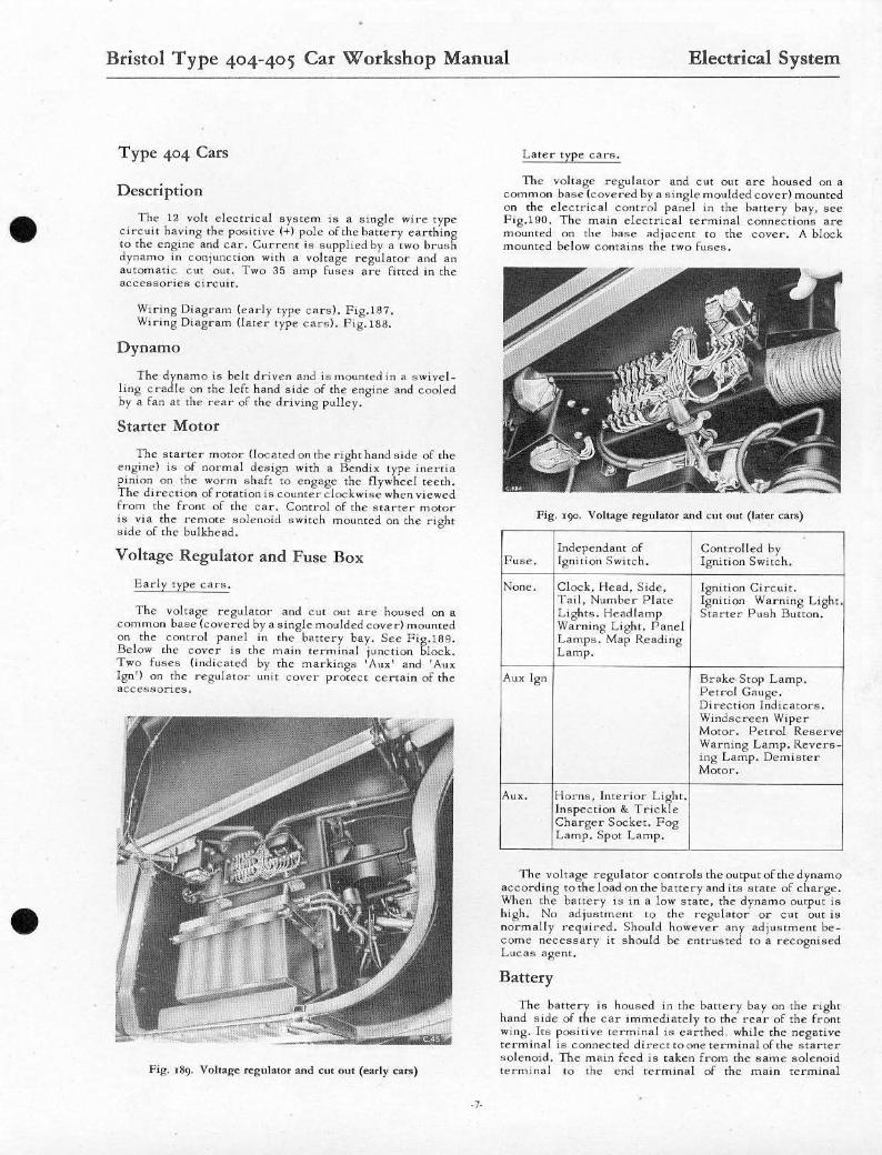
T he voltage regulator and CUt Out are housed on a com mon base (covered by a single moulded cover) mounted on the control panel in the banery bay. Sec Fig.ISO. Below the COVer is the m ain terminal junction block. Two fuses (indi cated by the markings 'lIux' and' AUI( Ign') on the regulator unit cOver protec t certain of the accessories .
Fig. 189. Vultage regu lator anti Cut oUl (early can!)
Later type cars.
The voltage regulator and Cut out are housed on a COmmon base !covered by a single moulded cover) mounted On the electrical control panel in the battery bay, see Fig.190. The main electrical terminal connections are mounted on the base adjacent to the cover. A block mounted be low comains the two fuses.
Fig. '90, Voltage regulator and cut om ( later cars)
Independant of Controlled by Fuse. Ignition S witch . Ignition Switch.
None. Clock. Head, Side, Ignition Circuit. Tail, Number Plate Ignition Wa "ning Light. Lights. Headlamp Starter Push Bunon. Warning Light. Panel Lamps. Map Reading Lamp.
Aux 19n Brake Stop Lamp. Petrol Gauge. Direction indicators. Windscreen Wiper Motor. Petrol Reserv Warning Lamp. Revers-ing Lamp. Demister Motor.
Au~. Horns, Interior Light. In''pec tion & Trick le Charger Socket. Fog Lamp. Spot Lamp.
The voltage regulator controls the output of the dynamo according tothe load on the battery and its state of charge. When the b~tlery is in a low state, the dynamo output is high. No adjustment to the regulator or C Ut out is normally ,·equired. Should however any adjustme nt become necessary it should be e ntrusted to a recognised Lucas agent.
Battery
The battery is housed in the battery bay On the rtght hand side of the car immediately to the rear of the front wing. Its positive tC"mina! is earthed. while the negative term i,,,. I is connected direct toone terminal of the starter solenoid. The main feed is taken from the sante solenoid terminal to the cnd r:erminal of the main terminal
Bristol Type 404-405 Car Workshop Manual Electrical System
junction block within the battery bay. See Fig.189.
Three different types of opening and loc king arrange_ menu are incorporated for the v ~rance doonl,
Early Iype cars.
Pull the knob in front door pdla(", "CC P'8.191. Ra.se the valance door un ti l s upported.
Pig. '9' , Tn~trlJmCIll pane l (ea rl y ca r~)
Intermediate type ca .. s.
Re leas e the locks at cach cnd of the valance door with the s quare key suppl ied. Ra ise the door und I aupported .
Laler Iype c a r s .
Rciell$c the toggle rastener on the undersIde of the pllnel. LIft the safety c a tc h sce Fig. 192 s ituated Il t the rear and rR'SC the door UOll! " upporred.
Fig. ' 92. OJ><'ning n l,.ncc door (late . ClII'lI)
Ammeter 11.c ammeter 18 lo c ircult WIth all e le c t ri cal accessor
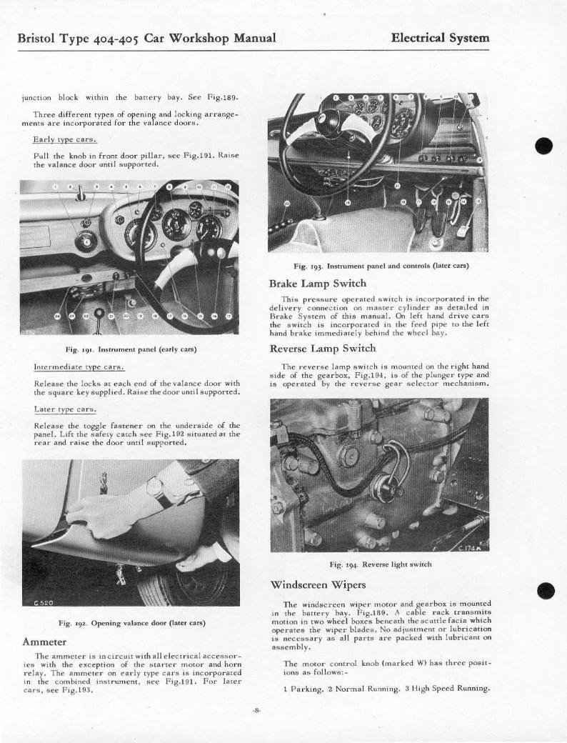
Ies wlIh the exception of thc .. Iarlcr mOl or aod horn relay. The ammete r on early t ype c nr~ i" inco" poratcd 'n the combincd in"frument. see '"'g.19 1. For later can, ace P'g.19.~.
·s·
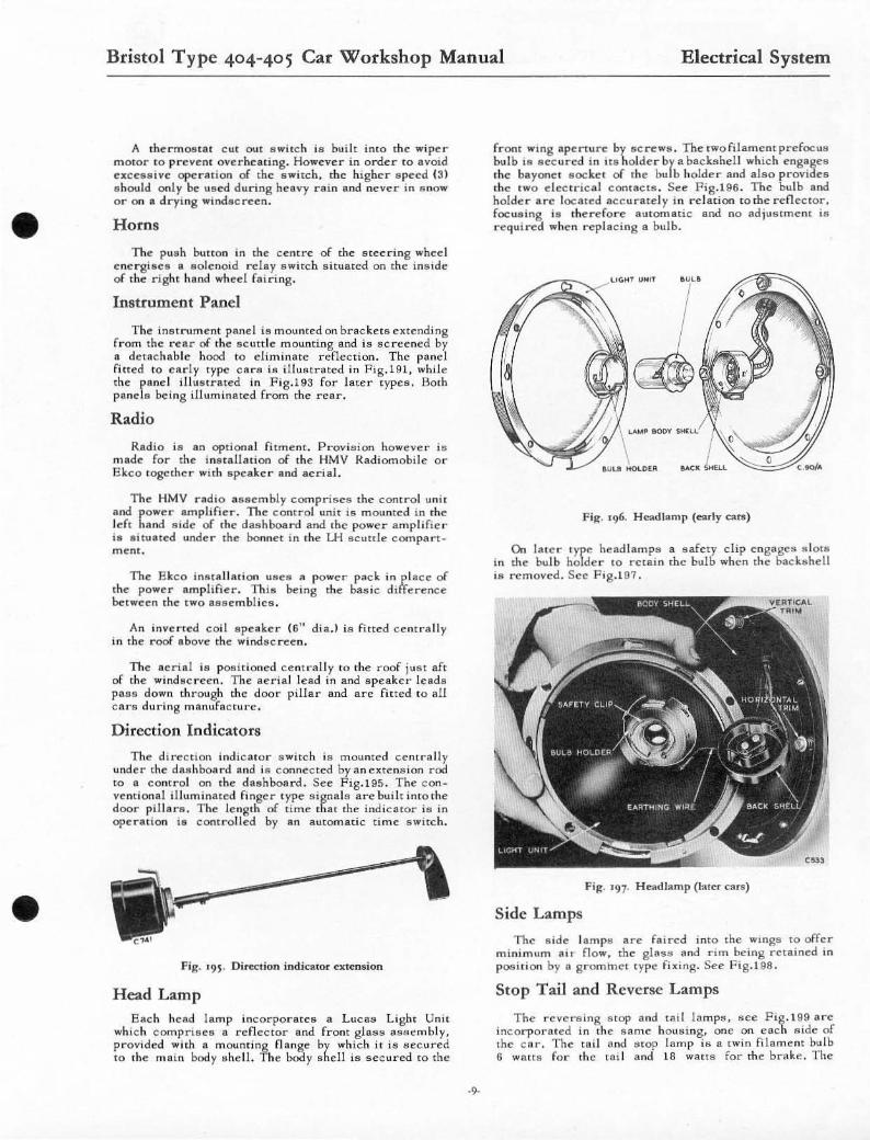
Fig. ' 93, h ... lmmenl p"nd and com m is (L"t~ r cars)
Brake Lamp Switch This pres .. ure operated swilc h , 11 mc orpor au:d in the
del ive r y c onneClLon on m aSter cyb nder as detad ed In
Urake S YStem of ,hia manual. On left hlllxl d rive c ars the .. wile h ,s incorporsted In the feed pipe ro the left h and brllke immedi atc!y beh",d th e wh eel bllY .
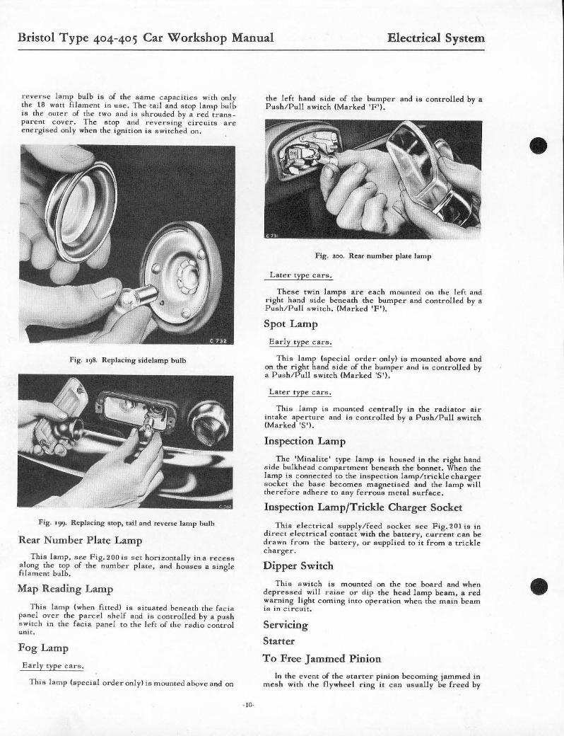
Reverse Lamp Switch
The "everse lamp aWHch.s mounted on the "ight hand tilde of the gearbox, F'g.194, is of the plunger type and is operated by the reverse gea r selector mechanism.
Fig. '94. Reverse light .witch
Windscreen Wipers
The windscreen wiper mOtor and gearbox is mounted in the battery bay. Fig.189. A csble raek t r ansmit .. m ot ion in tWO whe el boltc" benesth Ihe s c uttle racia whic h operates the wIper blade .. . No adjus lment or lubri cation , .. necessa r y as a ll pa rts are packe d with lubneam on assembly.
The motol' cont r ol knob (marked WI hlls three pos it _ ionll a .. rollow .. : .
1 Parking. 2 Normal Running. 3 High Speed Running.
•
•
•
•
Bristol Type 404-405 Car Workshop Manual Electrical System
A ther-moatal c ut OUI switch is built into the wipe r mOlor 10 p r event overheat ing. However in ani'!'''' to avoid cxcc88ivc operalion of the switch, the higher s peed {31 s hould only be ulled during heavy ra in and never in snow Or on 11 drying windscreen.
Horns
The pu,h buuon in the centre of rhe su:cring wheel encrgillclI a solenoid rclay switch s ituated on the inside of the right hInd wheel fa i ring.
Instrument Panel
The inlltrumcnt panel ill mounted on buckets exte nding from the rcar of the scuttle mounting and is screened by I!. detachable hood 10 eliminate .enettion. The panel fitt ed to early Iype ca rs is illu!ltratcd in Fig. l 91, while the panel illustrated in Fig.193 for later type .. , Both pands being illuminated from the rear.
Radio
Radio ia an optional fitme nt. Provision however i" made for the insu,[[ at ion of the HMV Radiomobile or 8kco logelher with speake r and aeri a l.
T he HMV radio assem bly comprises the control Unil and power amplifie r . The control unit is mounted In the Id t hand side of Ihe dashboa rd and Ihe power ampl ifie r i. s ituated unde r the bonnet in the LH scuttle compa r t _ ment .
The E keo inflt a ll alion usea a power pac k in p lace or the power amplifier. Thill being the basic difference between the tWO assembl ies.
An inverted coil speake r (6" dia,) is fitted centra lly in the roo£ above the windscreen.
The aerial ill posi tioned centrally to the roof just aft of the windecree n, The aeria l lead in and speaker lead .. pass down through the door pillar a nd are fitted to all e ar" during manufacture .
Direction Indicators
The direction indicator switch is mounu:d centrally under the dl\8hboard and i8 connec ted by an cxrcnsion rod to a cont r ol on the duhboard. See Fig.Uti. The c onventional illumil'lau:d finger type ... ignal ... arc built into the door pillar". The length of time that the indicator is in operation is conI rolled by an automatic ti me switch .
fig. 19S' Direction indicatot extension
Head Lamp Each hcad lamp incorporates a Luca" Light Unit
whic h comprises a renector and front glass assemb ly, provided with a mounting flange by which it is "ecured to the main body II he l l. T he body shell i ... secured to the
-9-
fron t wing aperture by screWII. Thetwofilamentprefocu8 bulb ill IIecured in ita holde r by a backshdl which engages the bayonel lIockel of the bulb holde r and al80 provides the t wO declncal contact". See Fig.196. The bulb and holder arc located accuratel y in relation lothe reflec tor, foculling ill therefore automatic and 110 adjuaunent ill r e quired when replacing a bul b.
Fig. '96. H eadlamp (early cars)
On later ' yr.e head lamp" a safety clip e ngages ,, 101" in ,he bulb ho der 10 reta in the bulb when the hackshell is removed. Sce Fig.197.
fig. '97, Headlamp ( latcr cars)
Side Lamps
The s ide lamp" arc fa ired imo the wmgs to offer m inimum ai,- flow. the glsss and rIm being retained in poshioll by !I g r ommet typc fix ing. See Fi g.198.
Stop Tail and Reverse Lamps
The rcvel's ms Stop a nd tat! lamps, sce Fig.199 arc incorporated m the same housmg. onc on each aide of the car. The toil and "top lamp is a twin filament hulb 6 waifS fo'- the tail and 18 watts for the hrllle. The
Bristol Type 404-405 Car Workshop Manual Electrical System
reverse Jamp bulb is of the "ame capacities with only the 18 watt filament in use. The ta il and stop lamp bulb is the Outer of the two and ill shrouded by a rcd trans_ parem cover. The stop and r",vcrsing circui ts are energised only when the ignition is switched on.
Fig. '98. Replacing sideJamp bulb
Fig. '99, Replacing SlOp. tail and reverse hlmp bulb
Rear Number Plate Lamp
This lamp, sce Fig.200ia sct horizontally ina recess along the top of the number plate , and house" a single filament bulb.
Map Reading Lamp
This lamp (when fitted) is situated beneath the facia panel over the parcel shelf and is controlled by a push switch in the facia panel to the left of the radio control unit.
Fog Lamp
Early type cars.
This lamp (special onleronlyl is mounted above and on
- 10-
the left hand side of the bumper and ia controlled by a Push/Pull awitch (Marked 'F' ).
Fig. wo. Rear number plate lamp
Later t ype cars.
The!!e twin lamps are each mounted on the left and right hand aide beneath the bumper and controlled by a Push/Pull switch . (Marked 'F'l.
Spot Lamp
Early type cars.
This lamp (spec ial order onlyl is mounted above and on the right hand side of the bumper and is controlled by a Pua h/Pull switch (Marked '5') .
Late r type cars,
This lamp is mounted centrally in the radiator air intake aperture and ia controlled by a Push/Pull switeh (Marked '5').
Inspection Lamp
The 'Minalite' type lamp ia housed in the right hand side bulkhead compartment beneath the bonnet. When the lamp ia connected to the inspection lamp/trickle charger socke t the base becomes magnetised and the lamp will therefore adhere to any ferrous metal surface.
Inspection Lamp/Trickle Charger Socket
This electrical supply/feed socket see Fig. 201 is in direct electrical contact with the battery, c urrent can be drawn rrom the battery, or supplied to it from a trickle charger .
Dipper Switch
This swi t ch is mounted on the roe board and when depressed will raise or dip the head lamp beam, a r ed warning light coming into operation when the main beam is in circuit.
Servicing
Starter
To Free Jammed Pinion
In the event of the starrer pinion becoming jamme d in mesh with the flywheel ring it can usually be freed by
•
•
•
•
Bristol Type 404-405 Car Workshop Manual Electrical System
removIng the prQ(cc ll ve cap, then apply a spanne r 10 the squared end of the arnlature s haft aod turning in a clod WIse dU'ccdOl'l vIe wed from the front cl the engine. Should penislcnl Jamming occur the scaner solenOId and m Olo r ahOll Jd be examined in accordance with the appropriau~ Lucas instructions .
Fig . :aol . 1r"'JlCcl ion lamp llnd trickle charger aocke l
Care of the Battery
Alwaya keep rhe top of rhe balte r y cle an and dry. S mear the cable termi nals with pctro lc \lm jell y toprevem corr or;c ion. Pe rIod ica lly a c hec k s hou ld be carried OUl on the level of the e lect r olyte in each cel l. The ratc of evapor31ion of t he elect r olyte varies according [0 rhe use of the hattery IInd the temperature in which it is ope rating. Never usc a naked light ove r cells , since the gas is explosive . If 'topping up' is req'-l ired, use only pure dhnilled WilIer whi ch must not contact metal (metal fun,>!:l or cnntainer). The tops of the plates should just be covered . Do not over fill since this will cause a viole nt disc hsrge of gas when the battery is being charged by the dynamo n:{!luiting in damage to the surrounding metal wor k.
Occllsionally tllke hydrom eter readings to check the condit ions of each c ell as followl'l :_
Hydrom<: t<: r r<:adings.
CHma!<:. Charged. 112 Charged Di sch a rged.
Temperate 1.2S0 to Approx. 1. 150 Or Up 10 800
P. 1. 300 1.210 less . (270 C.)
Sub-t ropical 1.250 to SOOp 10 lOOOF 1.270 - -1270 C 10 3SoC )
Tropical 1.220 to Over lOO"P 1.240 - -(38"0
· 11-
Brake Lamp Switch
Remov ing and refunng.
Du,"conne c t the c a bles the n unSCN: W and remove the s witch from the mal'lte r cy li nder, see Fig.202!; Refit the e wite h, connect the cables and fioall y bleed the brakes.
Fill:. 101. Brake lamp switch
Windscreen Wiper Motor
RemOVing and refin ing.
Remove the wiper a rms and blad<:s, disconnect the bSlle ry snd then the five c ables from the wiper mOlo r.
Rem ove the s c r ews atlach ing the wiper mOlor mounting bracket to the c ar hody and unsc r e w the nu t attac hing the c a ble c aai ng to the motor. Withdraw the m otor conlplete with tbe mounting brac ke t and the c able. De tac h the mounting br ac ke t from the motOr.
Shou ld 11 be p08l'1 ible to obtain a r<:p lacemem m otor with an identical length cable the existing c abl e ne t:d not b<: detacht:d. Pailing th is it will bc nec<:8ea r y to transfer the c able f, ' om tht: faulty mOlOr to the r eplac e_ meOl.
T o refit the m otor from this stage. fit the mounting bracket, IImea r the cable with greas t: and feed it through
Bristol Type 404-405 Car Workshop Manual Electrical System
cable CUing. fi nally screwing on the nut to secure casing to the motor. Attach the mounting b'".eke! to car body and reconnect the five cables to the motor.
Reconnect the batte ry and with the wipe r !lpindle!l in the sUltionary po .. ;tion, refit the wiper arms and blades and check the arc of wipe.
Horns
Ad justme nt . nd refitti ng.
The hOnl8 will give long periods of service without attention under normal cireumSlanCCII, If however the performance of one or both horns become" uncertain. make lIure that some outside source is "Ot the cauac of the trouble. ie, a lOOllc connection, hlown fuse or any loolle metal part. i n the viCinity of the horns which will vibrate when the horn is energised.
The adjustment provided in ellch horn wi ll take up we.r in Ihe moving parts but will nOI aff'ecl Ihe note pi tch.
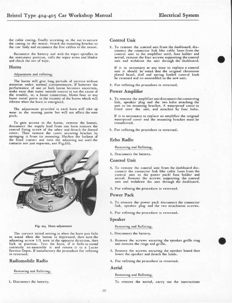
To g.in aeces. to the ho m s , r e move the bannel, d isconnecl Ihe " upply lead from onc horn remove Ihe centra l fixing screw of the olher and detach the domed cover. Then r emove the c over sec uring brscket by "pringing iI from its mounting. S IRcken the locknut of the fixed contact and turn the .djua ting nut until the cont'Cts ore jmlt separale, see Fig.203,
Fig. %0). Horn ad iu~lmenl
The correct 'mual setting IS when the horn JUSt fSl ls to sound whe n the button ,s dcpres sed, then turn the • djust ing acrew 1/2 turn in the opposite direction, then lock in position. Test the horn, if it fail", to "oun<! correc tl y rc-assemble it and retul"n it to a Luca" Service Depot. If satisfactory the procedure for refitting is revereed.
Radiomobile Radio
Removing and Refitting.
1. Disconnect the blltte ry.
· 12·
Control Unit
2. To remove the control unit from the dashboard, dis_ connect the connector link !thc cable loom from the control Unil to the amplifier unit!. fu " e holder and aeriel. remove the four screwa eupporting the c ontrol Unil and wilhdra .. the unil through the dashboard.
If ;, is necessary at any time 10 ..-eplace a conlrol unit i l s hould be noted that the original ch romium plated bezel, d ia l and s pring loadeiJ control knob be relained a..d r e- assembled 10 Ihe new unit.
3. For refitting the procedure is reversed.
Power Amplifier
4. To remove the amplifier unit disconnect the connecting link, s peaker plug a nd the two bolts attaching the unit 10 i ls mounting b r acket . A waterproof cover is fi tled over th e unit, and a ltached by four bol ts.
If it ia ne cessary to r eplace an a m p lifi e r Ihe original wSlerproof cove r and the mounting bracke t must be trsnsferred .
5. For refilting the procedu ..-e ia revers ed.
Echo Radio
Removing and Refiuing.
1. Disconnec t the batte ry.
Control Unit
2. To remove the cont rol unit from the das hboard di,,conneCI Ihe conneCtor link hhe cable loom from the control unil to the powe r packl fU 8e holder and ae rial. Remove the IICr e1Ve lIupporting the control unil !l.nd wi thdraw th e uni t th rough the da sh board.
3. For refitting the procedu r e i ll revereed.
Power Pack
4. T o r emove t he powe r pack dieconnecI the conneCfOr li nk , s peake r plug IInd the two attachment sc r ewa.
5. For r e fining the procedure ia reversed.
Speaker
Removing and Refi tt ing.
1. Disc onnect the battery .
2. Rcmovc the screws securing the 8peaker grille ring !l. nd remove the ring ... and grillc.
3. Remove the sc rews securing Ihe epeaker hoard then lowe r Ihe speaker and det.ch the leads .
4. For refitting the procedu re is reve rsed.
Aerial
Removing and Refitting.
To remove the aerial, carry OUt the instructions
•
•
•
•
Bristol Type 404-405 Car Workshop Manual Electrical System
for removing the speaker. then disconnect the aerial lead and remove the hexagonal screw securing the aerial. Remove the aerial and insulat ing grommet.
For refitting the procedure is reversed.
Direction Indicators
Removing and Refitling.
Release the quarter light fillet screws. remove the door aperture fillet and interior roof light OIwitch (RH side pillar only). Re move the indicator trimming panel. remove the two screw .. securing the indicator bracket to the door pillar. Disconnect the single wire from the indicator and remOve the sCrew securing the indicator to the brad::ct.
For refitting the procedure is reversed.
Direction Indicator Switch
Removing and Refitting.
1. Working from beneath and to the rearofthe dashboard remove the 6 BA screw securing the extension shaft to the sleeve, see Fig,19!;.
2. Remove the ri ng nut and washer.
3. Disconnect the cables and remove the switch from its support bracket.
4. For refitting the procedure is reversed.
Note. If a replacement switch is fitted the sleeve must be transferred.
Removing and Refitting Instruments
Speedometer and Revolution Counter
Early type cars. Sce Fig. 204.
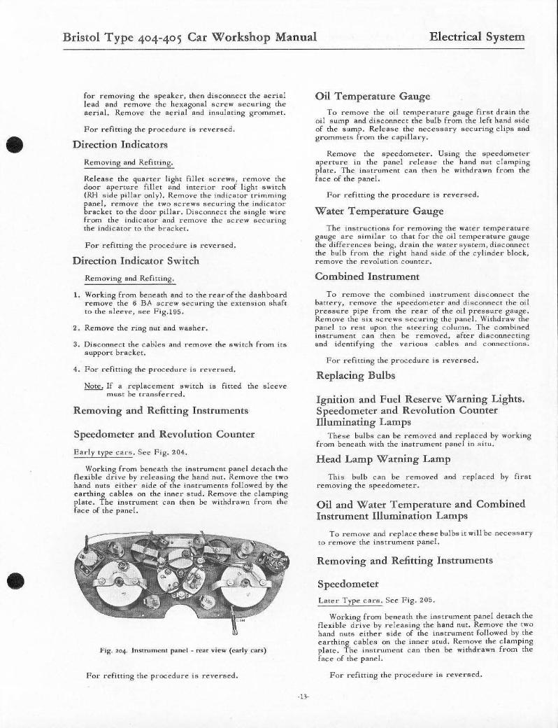
Working from beneath the instrument panel detach the flexible drive by releasing the hand nut. Remove the two hand nuts either side of the instruments followed by the earthing cables on the inner stud. Remove the clamping plate. The instrument can then be withdrawn from the face of the panel.
Fig. 204. Instrument panel _ rear view (early cars)
For refitting the procedure is reversed.
-13-
Oil Temperature Gauge
To remove the oil temperature gauge first drain the oil sump and disconnect the bulb from the left hand side of the sump. Release the necessary securing clips and grommets from the capillary .
Remove the speedometer. Using the speedometer aperture in the panel release the hand nut clamping plate. The instrument can then be withdrawn from the face of the panel.
For refitting the procedure is reversed.
Water Temperature Gauge
The instructions for removing the warer temperature gauge arc similar to that for the oil t emperature gauge the differences being. drain the water .. ysrem, disconnect the bulb from the right hand side of the cylinder block. remOVe the revolution counter.
Combined Instrument
To remove the c ombined insn'ument disconnect the battery, remove the speedometer and disconnect the oil pres,mre pipe from the reOr of the oil pre .. sure gauge. Remove the sill; screws securing the panel. Withdraw the panel to rest upon the steering c olumn. The combined insU'un'ent can then be removed. after disconnecting und identifying the various cables and connections.
For refitting the procedure is rcversed.
Replacing Bulbs
Ignition and Fuel Reserve Warning Lights. Speedometer and Revolution Counter Illuminating Lamps
These bulb" can be removed and replaced by working from beneath with the instrument panel in situ.
Head Lamp Warning Lamp
This bulb can be removed and replaced by flnn removing the speedometer.
Oil and Water Temperature and Combined Instrument Illumination Lamps
To remove and replacerhesebulb"jrwillbe necessary to remove the instrument panel.
Removing and Refitting Instruments
Speedometer
Late r Type cars. Sce Fig. 205.
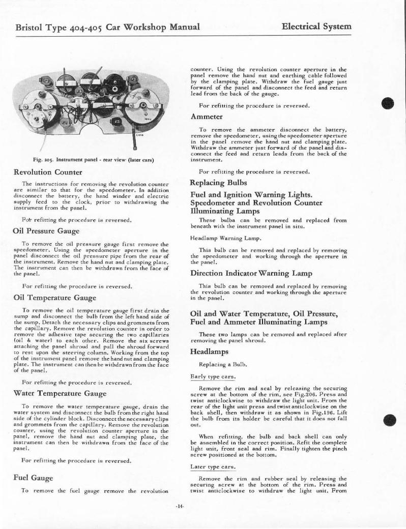
Working from beneath the instrument panel delachthe flexible drive by releasing the hand nut. Remove the tWO hand nuts either side of the instrument followed by the earthing cables on the inner stud. Remove the cl amping plate. The instrument can then be withdrawn f"om the face of the panel.
For refitting the procedure is reversed.
Bristol Type 404-405 Car Workshop Manual Electrical System
I
Fig. 10~. Jnururncnt panel - rear view' ([at". c;Rn)
Revolution Counter
The instructions for removing the revolution counter arc sunilar 10 that for the s peedomeTer. In additi on disconnect the battery, the hand winder and electric supply feed [0 the doc k, prior to withd r awing the ina trument from the pane l.
Fo\- refitting the procedu re i .. reversed.
Oil Pressure Gauge
To remove the oil pres" ", r e gauge first n:nlOvc the speedometer. US ing the speedometer apen ... r e i n th" £land d iscoronecl the o il pressure pipe from the rca r of the instrument. Remove the hand nut and clamping plate. The lmltrum enr can then be withdrawn from the fac e of the pRnel.
For refini ng the pr·ocedu .-" is r eversed.
Oil Temperature Gauge
To remove the od te mperature gauge first drain the s ump and disc onneCt the bu lb from the Icft hand s ide of the sump. Detach the necesllary clips nndgrommet" from the capillary . Remove th e revolu tion counter in or der to remove the adhesive tape sec uring the tWO capillaries (oi! &. water) to each othe r. Remove the s ix Mcrews (llIac hing the pnnel s hroud and. pull the s hroud fo rward to r cst upon the s lee"'ng column. Wor ki ng from the top of the ins lrumen! pane l rem ove the hand nut and clamping plsle. The intHrum!':m can the n be withdrawn fr om the face of the pllnel .
Par refitting the procedure is rever s ed.
Water Temperature Gauge
To remove the water temperature gauge . drain the water system and dlllconneCt the bulb fr om tne righ t hand Side of t he cylinder bloc k. Di llconnec t the nec e ssary clips and g romme ts from the csp illary . Remove thc r evolution COunter. using the revolution COUnter aperture in the pane l, remove the hand nut IInd clamping plate , the instrument c an then bc wi lhdl' awn from the fac e of the panel.
For refitt ing the procedure is r eve r sed.
Fuel Gauge
To remove the fud gauge remove the I'evolution
- 14-
counte r . Using the revolution counter ape r tur e in the panel r e move the hand nut and earthing cable foll owed by the clamping plate . Withdraw the fu el gauge JUSt fo rward of the panel and d isconneCt the feed and return lead from the back of the gauge.
For refitting the procedure is reveraed.
Ammeter
To remove the ammete r disconnect the batte r y. remove the s peedomete r . us ing the speedome le r apertu r e in the panel remove the hand nul and clamping plate. Withdraw the ammeter jus t fo rward of the panel and dis_ connec t the feed and return leads from the back of the imllrument.
For refi tt ing the procedure is reversed .
Replacing Bulbs
Fuel and Ignition Warning Lights. Speedometer and Revolution Counter Illuminating Lamps
Thes e buJba can be removed and rep laced. from beneath with the ins lrument panel i n situ.
Headlamp Warning La mp .
Th is bulb c an be removed and replaced by removing the speedomete r and worki ng th r ough Ihe aperture in the panel.
Direction Indicator Warning Lamp
This bulb can be removed and. replReed by removing the r evolution counter and working th rough the aperture in the panel.
Oil and Water Temperature, Oil Pressure, Fuel and Ammeter Illuminating Lamps
These two lamp" c an be r emoved a nd repl aced afte r r emoving the panel shroud.
Headlamps
Re p lac ing a Bulb.
ERrly type cars.
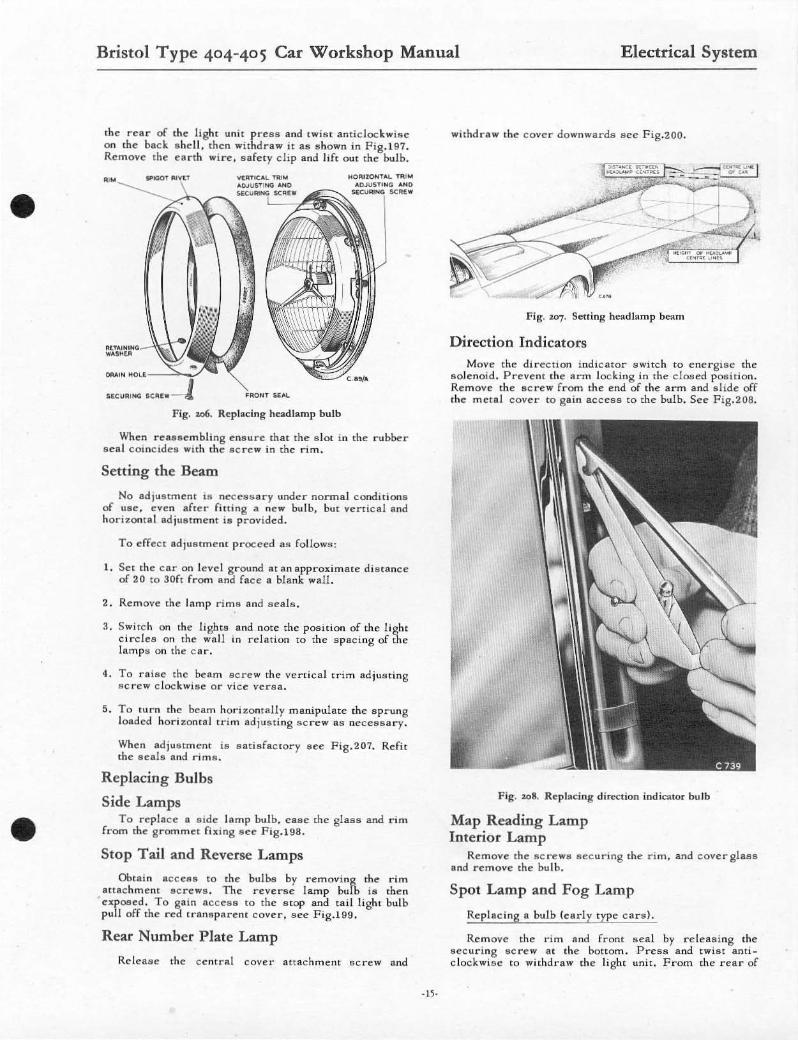
Remove the rim and se d by re le as ing the "ecuring screw at the bOltom of the rim. sce Fig.206. Pres s and. t ... ist Rnticlockwi se to ... ithdraw the light unit. From the rear of the light unit pres .. and. twi .. , a nticlockwise on the back she ll. then withd .. "w it as s hown in F ig. 196. Lift the bu lb rrom its holde r be c a refu l that it does nOl fall out.
When refining. the bulb and back ahell can only be a " semhled in tne correct position. Refit the complete light unit, front seal a nd rim. Final ly tighten the p inch acre ... positioned at the bottom .
LaTer type cars.
Rem ove the rim Rnd rubbe r seal by releasing the aecu ring sc r ew at the bottom of the rim. Press and twis t a nti clockwise to withdraw the light unit. From
•
•
•
•
Bristol Type 404-405 Car Workshop Manual Electrical System
the rear of the light uni t p rcss and twis t anticlockwise on the bAc k ahel l , then withdraw it as s hown i n Fig. 19? Remove Ihe ea r th wire, safety clip and lift OUt the bulb.
UcuR<MG ."".- -,1 F ig. 106. Replacing headlamp bulb
HO .... lON1 ..... Till" AOJUs .... G .... 1)
J,C~l •
When reassembl ing e nsure that the a lC)( in the rubber seal eomCldea wLth the II c rew in the rim.
Setting the Beam
No ad justment is necessary unde r norma l conditions of use. even afu: .. fini ng a new bulb, but vertical and horizollls l adjustment ia prOVided.
To effect ad )tunmem proceed as follows!
1. Set the e n-r on level ground at an approximatt: dis tance of 20 to 30fl from and face a blank wall.
2. Remove Ihe lamp rim!! and seals .
J. Switc h on the lighu a nd nott: the position of the light cirdea on the wnl! in relation to the spaci ng of the lamps on the c ar.
4. To raille the beam acre w the vertical t.-im ad ju;l ting Acrew dockwille or vice vcraa.
S. To lurn the beam horizont ally manipulate the IIprung loaded hori zontal trim adj usting screw as necessary.
When adjustment is satisfactor y 1Iet! F ig.207. Refi t the scala and rims.
Replacing Bulbs
Side Lamps To replace a a ide lamp bu lb, case the glass and rin •
from the grommet fbong sce F ig. 198.
Stop Tail and Reverse Lamps
Obtain access to the bu lbti by removing the rim attachm ent sc rews. The reverse lamp bulb ill the n expOlled. To gain ncceslI to the IItop and tail light bulb pul! off the red transparent cover. see Fig.199.
Rear Number Plate Lamp
Release the central cover attachment scre w and
withd raw the c over downwards see Fig.200.
Fig. a07. Setting headlamp bellm
Direction Indicators Move the direction indicator "witc h to energise the
lIolenoid. PreVent the arm locking in the dosed position. Remove the IIcre w from the end of the arm and slide off the metal eover to gain aecess to the bulb. See Fig.208,
Fig. 308. Replacing dirc-ction indicator bu lb
Map Reading Lamp Interio r Lamp
Remove the s c rews sec uring the r im. and c overglaas and remove the bu lh.
Spot Lamp and Fog Lamp
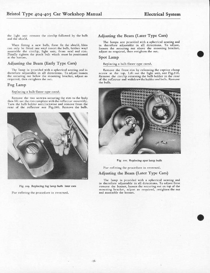
Replacing a bulb (early type cars) .
Rem ove the dm and fron t seal by releasing the securing 8c r e w at the bottom , Pre'u, and twilit anri_ c10ckwille to withdraw the light unit. F rom the r ear of
Bristol Type 404-405 Car Workshop Manual Electrical System
the light unit remove the circlip followed by the bulb and the shield,
When fiuing a new bulb, first fit the s hield, (this Can on1r be fitted one way) insert the bulb, (e ither way) asscmb e the circli p, light unit, front seal and rim. Finally tighten the pinch bolt which must be p05itioned at rhe bottom.
Ad justing the Beam (Early Type Cars)
The lamp is provided with a spherical sCllting IInd is therefore adjustable in all directions, To ad just loosen the s,",curing nut below the mounting bracket, adjust as required, then redghtcn the nut.
Fog Lamp
Replacing a bulb (later type cars!'
Remove the TWO "crews securi ng the rim ro the body then lift out the rim complete with the refl ector lI!1scmbly. Turn the bulb holder lInt.iclockwise and remove from the rcar of the reflector see Fig.a09. Rcmove thc bulb.
Fig. 109. Replacing fog lamp bulb later cars
For refitting the procedure is reversed.
Adjusting the Beam (Later Type Cars)
The lamps are provided with a spherical seating and is therefore adjustable in all directions. To adjust . loosen the securing nut above the mounting bracke t. adjust as requi r ed, then re tighten the nut.
Spot Lamp
Replacing a bulb (la te r type cars).
Remove the front rim by releaSing the c aptive clamp SCreW lit the top. L ift out the light unit, see Fig.210. Remove the circlip retaining the bulb holder in the rear of the r eflector and withdrswthe holder and bulb. Remove the bulb.
Fig. no. Replacing spot lamp bulb
For r efitti ng the procedure is reversed .
Adjusting the Beam (Later T ype Cars)
The lamp is pl:"ovided with a sphe rical seating and is therefore adjustable in a ll directions. To adjust first removc the bonnet, loosen the secul:"ing nut on top of the mounting bracket, adjust as required, retighten the nut and assemble the bonnet.
•
•
•
•
Bristol Type 404-405 Car Workshop Manual
Regulator Unit
Fuse Base
Bllucry
Switches
Wmdscreen ...
Lamp!! ...
Warmng Lamps ...
Fuel Gauge
Ammeter
Pet rol CRuge F loal Un;!
Pe trol RCllcrve Unit
Panel LIght ...
Type 405 Cars
General Data
T ype Capacity
Lighting &. Igni tion Panel Light Rheostat Horn Relay Flasher Unit Double Relay for Flasher!! Petrol Rese rve Inte rior .. . Starter .. . Dipper '" Fog SpOl Reverse .. Sta rter Solenoid ... Windacreen Wipe r
~:I~yL:t~ &'Sp~')' Boot Lighi Overdrive
Motor I!r. Gea rbox Wiper Arm ... Wiper Blade ..
Head Side Combined Stop . Rear, Dirccdon Indicator <I. Reflector Number Plale &. Rcvenlc '" Fog .. Spot. Interior ,_ """,. Map Reading. Im.peclion
Main Beam (Red) Ign itIon {Am berl... . .. Petrol Reserve (Blue) . Direction Ind ic ll lo '-
- l7-
Electrical System
Lucas RBI06/1. (Early T ype Cars) Lucas RB320. ILater T ype Cars)
Lucas SF6
Luess GTW9A12 51 Ampere hours at 10 hr. rate.
LUC8S PR.$3 Lucils CHRl Lucas S840/1 LUC8S FL5 DBI0 Luca" PSISll Wdrnot Brcedon 8715B Lucas $S5 Lucas 1-"522 PS1 6 PSI6 ss 10 ST 950 Lueas PRS5 T r,co GSOO/B Lueae L1R. ( Late r Type Cars) Lueas 94 Lucas 31500B
Lucils 15232A Luc8ll 141831 Lucas 738735
LUCRS P.100 Lucas 539 Lucos 551
LUCRe 469 Marchal Recrilux 650 Lucas SLR576 S W;]mol B,·ccdon 121 36 Desmo24 4 Desmo244 Minalue
LUC88 WL12 Lucas WL 12 Luc as WL 12 Luc as WL 12
Smiths X494221232
Sm iths UM4
Smuhs Y86049
Luci\s 78029A
Luc aa PL3 I
Bristol Type 404-405 Car Workshop Manual
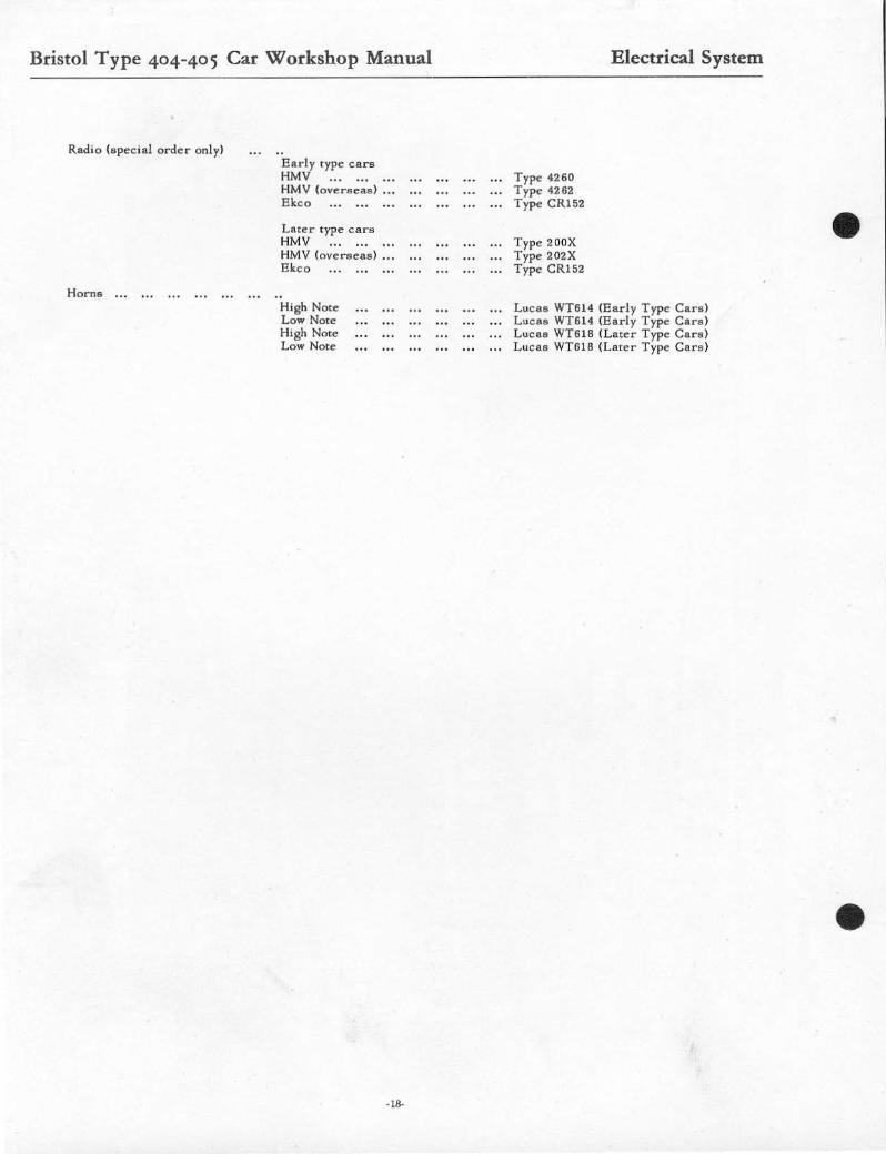
Radio (special order only)
Horn8 ...
Early Iype care HMV HMV (overseae) ..• Ekeo
Llltcr fype cars HMV HMV (over-aces) ." Ekeo
High Note Low Note High Note Low Note
· 18.
Type 4260 Type 4262 Type CR152
Type 200X Type 202X Type CR152
Electrical System
Lue •• WT614 (E arly Type Can ) Lueu WT6 L4 (Early Type Cara ) tucu WT61B (Later Type Can ) LutBII WT61B (Later Type Car8)
•
•
•
Cli. IIII I
. :m l/"!P" i I B~ 0
~ "- '" • "Ji" • "- 0" ~ , • 0
I " /
3 , •
~~ " .-
• ~~ '0. ,,:::1 , " . o ~
) ,
l=I:Ii [[ [
I, : • I·
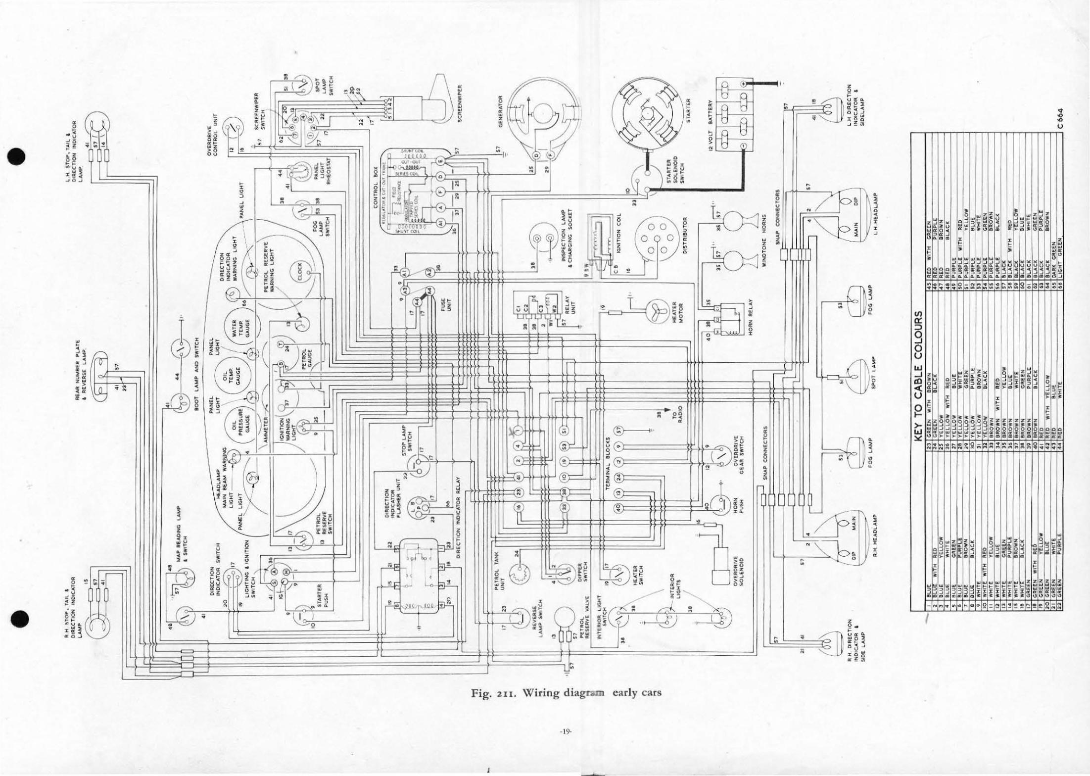
Fig. 21I. Wiring diagram early cars
J
·0 :!:(j
H" " L J >0 _0.
, • , . • . ;; 0« .0, !!':!<. ... ,clO oo~ • 1:1'i~ • ,- • ~-. u
S~ <~ " i~ z~ ~" w·
"
z ~ ~ • • ~ ~
§
~ o z _.u w,_ ".' .~. - . ,
w 0 a
~- 0 w~
~ ~
,
,
~
t • :::;!.l---L~,:./ 1
•
~ ~ • " ,. z " ~
•
Fig. 212 . Wiring diagram later cars
-.ll'-
•
•
•
Bristol Type 404-405 Car Workshop Manual Electrical System
Type 405 Cars
Description
The 12 volt electrical system i,. a single wire type circuit ha ving the positive (+) pol e of the banery earthed to the e ngine and boor, see Fig.211for carly type Cars and Fig.212 for later type cars. Current is supplied by a two brush dynamo in conjunction with a voltage regulator (on later type cars combined currem/voltage regu lator) and an automatic cut out. Two 35 Amp. fuses are fitted in the accessories circuit.
Dynamo
The dynamo ia belt driven and is mounted in a swivelling cradle on the left hand side of the engine and cooled by a fan at the rear of the dynamo.
Starter Motor
The "tarter motor (located on right hand side of the engine) is of normal design with a 'Bendix' type inertia pinion on a worm shaft to e ngage the flywheel teeth. The direction of rotation is counter clockwise when viewed from the from of the car. Control of the starter motor is via the remote "olenoid switch mounted on the right hand side of the bulkhead.
Voltage Regulator and Fuse Box
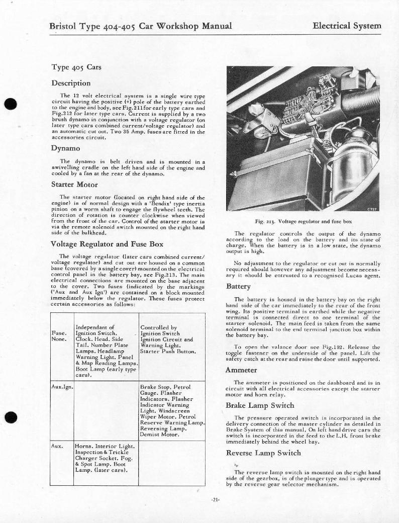
The voltage regulator (later cars combined currentl voltage regulator) a nd cut out are housed on a common base !covered by a Single cover! mounted on the electrical control panel in the battery bay, see Fig.213. The main electrical connections are mounted on the base adjacent to the cover. Two fuses {indicated by the markings ('Aux and Aux Ign') arc contained on a block mounted immediately below the regulator. These fuses protect certain acce!lsories as follows:
lndependant of Controlled by Fuse. Ignition Switch. Ignition Switch None. Clock. Head. Side Ignition Circuit and
Tail. Number Plate Warning Li~ht. Lamps. Headlamp Starter Pus Button. Warnin~ L1iht. Panel at Map ca ing Lamps. Boot Lamp (early type cars).
Aux.lgn. Brake Stop. Petrol Gauge. Flasher Indicator... Fla"her Indicator Warning Light, Windscreen Wiper Motor. Petrol Reserve Warning Lamp Reversi;1, Lamp, Demist otor.
Aux. Horns , Interior Light. inspection at Trickle Charger Socket. Fog, &. Spot Lamp. Boot Lamp. (later cars).
· 21·
Fill:. 213. Voltage r"guiator and fuse box
The regulator controls the output of the dynamo according to the load on the battery and it" state of charge . When the battery is in a low state , the dynamo output is high.
No adjustment to the regulator or Cut out is normally reqUired should however any adjustment become neCess_ ary it !lhould be entrusted to a recognised Lucas agent.
Battery
The battery is housed in the battery bay Oil the right hand side of the car immediately to the rear of the front wing. Its poaitive terminal is earthed while the negative terminal is connected direct to onc te rminal of the starter .. olenoid. The main feed is taken from the same solenoid terminal to the end terminal junction box within the battery bay.
To open the valance door sce Fig.192. Release the toggle fastener on the underside of the panel. Lift the safety catch at the rear and rai!le the door until supported.
Ammeter
The ammeter i .. positioned on the dashboard and is in circuit with all electrical accessories e~cept the starter motor and horn relay.
Brake Lamp Switch
The pressure operated switch is incorporated in the delivery connection of the masrer cylinder as derailed in Brake System of this manual. On left hand drive cars the ..witch is incorporated in the feed to the L.H. from brake imm",diately behind the wheel bay.
Reverse Lamp Switch
" The revers", lamp switch is mounted on the right hand
side of the gearbox, is oftheplungertype and is operated by the reverse gear selector mechanism,
Bristol Type 404-405 Car Workshop Manual Electrical System
Overdrive Switch (Gearbox Operated) The overdrive swhch is mounted 0f'I the gear 1.0,. lOp
cover fo r ward of the gea r change turret assembly. The switch IS of the p lu nger type and is only operative in top gear, when the manud switch on rhe daahboaro is in the 'on position'.
Windscreen Wipers
The windscreen wiper m otor and gcarooJt arc mounted on the electrical comrol panel in the hane ry bay. A cable r ack trans mits motion to two wheel boxes beneath the scuttle facia , .... hich operalell the wiper blade"" No adjustment or lubrication ia ncce'lsary 811 all parts are packed wi th lubricant on assembly.
The windscreen wiper control knob (M arked W) ia on the righl hand wide of the instrument panel and hat! three poaitions .8 foll OW8 :
1. Fast 2. Slow. 3. Parking.
A thermostatic CUt OUt swilch is to prevent overheating. Howevcr cxces!!Iive operation of the switch 8hould only be ulled during heavy snow, or On a drying wind sc reen.
Horns
built into the motor in order to avoid the f!lllt s peed ( 1) rain. Rnd never in
The push button in the centre of the s teering wheel energises a solenoid rday switch situated on the inside of the right hand wheel fairingto therear of the radiator . Thc horn!! on early cars an: fitted one on each s ide be. tween the radiator core and the front grille. and on la ter cers one above the other on the left hand side.
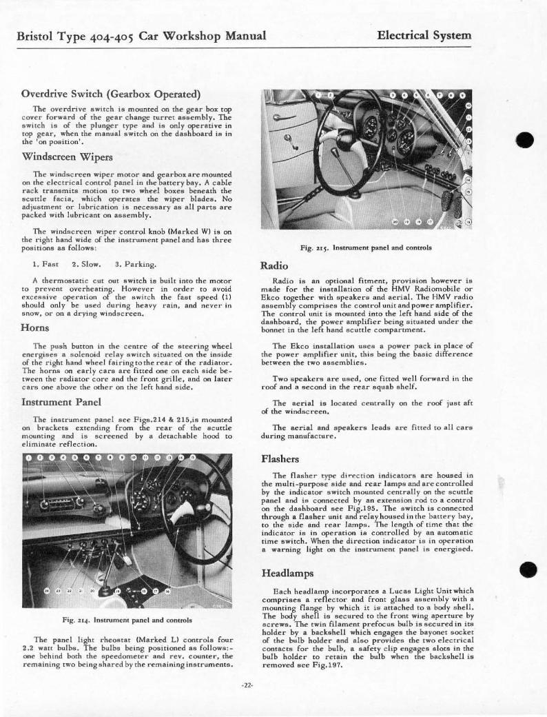
Instrument Panel
The inatrument pand scc F igs.214 & 215.is mounte d on bnekcts enending from thc rear of the scuttle mounting Rnd ill screened by a detachable hood to eliminate reflection.
Fig. i 14 . Inst rument panel and C(ln tro ls
The panel light rheostat (Ma r ked LI COfnrol s fou r 2.2 watt bulbs. The bulbs being posit ioned ... foll owlI:. one behind both the speedomete r and rev. counter, the remaining two being shllred by the remaining in!llrument s .
·22·
Fig. i l j. Inst rument panel and control.
Radio Radio is an optional fitment, provision. however ia
made for the instll.ilMion of the HMV Radiomobile or Ekco together wilh spe akers and aerial. The HMV radio as sembly compri.!lell the control unit and powe r amplifier. The control unit is mounted into the left hand lI ide of the dllahboard, the power IImplifier being lIitullted under the bonnet in the left hand ac utt le c ompanment.
The Ekco instllllarion Ullell a powe r pack in p lace of the power amplifi e r unit , this being the bas ic difference between the t ... o naemblies.
Two s peakers are used, one fitted well forward in the roof and a second in the rear squab shelf.
The aerillI is locau:d centrally on lhe roof just afl of the windsc r een .
The aerial and speakera lead .. are filled to a ll c ars during manufacture.
Flashers
Th.., flasher type direction indicatore are houlled in the multi.purpose a ide and rear l amps and are comrolled by the indicator s witch mounted cenll'ally on the scuttle panel and is connected by an extension rod to a control on the d.shboard aee Pig.195 . The a witch ill connected through a flallher unit and relay housed in the battery bay, to the side and rear lamps. The Icnglh of time that the indic ator ill in operation is controlled by an automatic time switch . When the direction indicatol' is in operation a ... arning light on the instrument panel ill e nergil!lcd,
Headlamps
Each headlamp incorporate!! a tucas Light Unit which comprises a reflector and from glass 8I!Isemhly with a mounting flange by which it is attached to a body IIhell. The hody shell is secured to the front wing aper ture by acrewa. The twin fil a ment pre focus bulb is secured in itoil ho lder by a bac kshell ... hich e ngages the bayonet socket of the bulb holder and also provides the tWO e lect rical comacts for the bulb, • s afety dip ellgagc lI a lotll in the bulb holder to retain the bulb when Ihe backshell is removed see Fig.197.
•
•
•
•
•
Bristol Type 404-405 Car Workshop Manual Electrical System
Side Lamps Each l!I iddamp hOUSing ;s buil! into the from wing the
eove r glas8 and integra l r im p r otruding beyond the wing surface. The lamp is fined with a twin fi iam " m bu lb, 6 wall for the a ide [amp and 2 1 wan for the 'Flasher' direction illdicator. The glas8 and rim is reta in"d by a bayonet type fill ing Sec P ig.216.
Fig. u6. Siddamp
Stop Rear and D irection Lamps and Reflectors
The muhi .purpoee lamps each incorpor au: a twi n filament bulb, 6 wat! for the rellrlight and 21 wan for the flaehcr and atop light. The regulation type reflector is incorporated within the mou lded glasl:! cover, Th" gl ase and rim is retained by a bayonet type fi xing ace Fig.217.
Fig. u 7. Stop. rear and dirCC'l ion l:!. mps and reflectors
Rear Number Plate Il1umination and Reverse Lamp
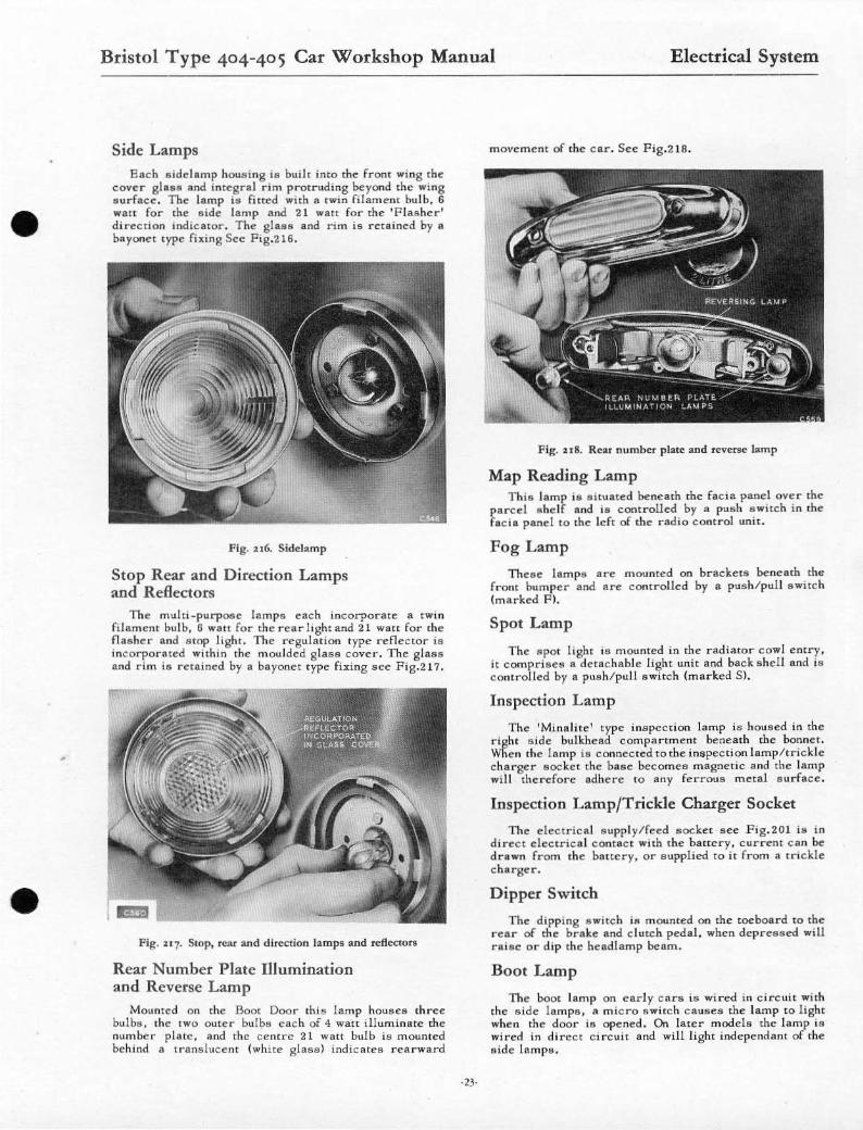
Mounted on the Boot Door this lamp houses three bul bs. the IWO outer bulbs each of 4 watt i lluminate the number plate. a nd the cemre 2 1 wall bulb is mounted behind a Iramliuce nt (white glass) indic ates rearwa rd
-23-
movem ent of the cat". See Fig.2 16 .
FIK. u6. Rear number plate and revene Lamp
Map Reading Lamp This lamp i lll situa ted hcnell th the facia pand ove r Ihe
pared " hel f and is ConI rolled by a pus h s ",i !.Ch in the fa cia panel w the left of the rad io control unil.
Fog Lamp
Theae lamps are mounted on brackets hcneath tbe f r on t bumper and are cont r olled by a pus h/ pull awiteh (marked PI.
Spot Lamp
The apot light ia mounted in the radiator cowl e ntry . it compriee8 R detachable light unit and back s he ll Rod ia controllcd by a push/pul! swi lch (m arked SI.
Inspection Lamp
Tbc 'MinRHte' type ins pection lamp is housed in the right s ide bulkhead compartment beneath the bonnel. Wllen the lamp is connect ed to the inspec tion lamp /trickle charger socket the base becomes magnetic and the lamp will therefore adhere w any ferrous m eld .. urfRce .
Inspection Lamp/Trickle Charger Socket
The electrical supply/fe ed socket sec F ig.20 1 ia in d irect dectric a l c ontac t with the bau e' r y. c ur r ent can be drawn from tbe battery. o r s upplied to it from a lri ckle charger.
Dipper Switch
The dipping a witch is mounted on the toeboa rd 10 the r ear of the brske and clutch pedal , whe'n depressed will r aise o r d ip the headlamp beam.
Boot Lamp
The hoot lamp on ea rl y c ars is wired in ci t"cuit with the side lamps, a m icro swilch c auses the lamp to light ... he'n the door is opened. On later models the lamp is wired in direct Circuit and will light indepe ndant of the aide' l ampa .
Bristol Type 404-405 Car Workshop Manual Electrical System
Warning Lamps
Ignition Warning Lamp 1nill ill s ituated on the bottom of the instrument panel
to the left of rhe flIteed ng column. The bulb ;1I fitted behind the amber glas s and comes incooperat ion when the ignition ia Bwitched 'ON',
Head Lamp Warning Lamp
This is sirullu:d on the top lcflh.nd lIidc of the stceri ng c olumn. The bulb ill lhled behind a rcd g1a88 and cornea imo operation when headlam ps are on main beam.
Fuel Warning Lamp
Th;8 is .;tuated on the bortom right hand side of the s teering column. The bulb ia fined behind a blue g lass and onry appear s whe n the pet rol reservc awitch and ignit ion ia switched on.
Direction IndicatorWarning Lamps
This ia aituatcd on the top righ t hand s ide of me stee ring column. The bulb i ll fiued Gehind a g reen glass and winks simultaneous ly with the fla s hing indic atorll.
Overdrive Switch (Manual) (Scc Fig.219.)
This is mountcd in a panel to the right of rhe inatru_ me nt pane l. Overdrive ia only incorporlltNIn top gear, the switch is s elf c ancelling when c hanging down from top gear.
Fig. 1II1J. Overdrive switch (manual)
Servicing
Starter . Aa for T ype 404.
Ca re of the Battery, As for Type 404.
Brake Light S witch. Aa for T ype 404.
Windsc reen Wiper Motor. All for Type 404.
·24-
Horns Adiustm em and Re fi n ing.
The horns will g ive long periods of /:Iervice without attention under normal ci r cumstances . If however the perfonnllnce of one or both horns becomes uncertain, make a ure tha t s ome outside sou rce ill not the c ause of the t r ouble ie, a JOOfIe cOl'meetion, blown fuse or any loose paris in the vicinity of the horna which will vibrate when the horn ill energised.
The adjustment provided in each horn will take up wear in the m oving parts but will not affec t the noise pitc h.
To adjua t the horns the following procedure should be c arried OII t:-
Early t ype carll.
1. Remove the bonnet. 2. Remove the cenu'al fixing II c rew and domed cover
from one horn and detach tne s upply lead. Cll r e 10 be ta ke n not 10 s hort e ircuit rhe wiring.
3. Re m ove the central fixi ng sc rew and domed cover from the other horn And then remove the cover securing bracket by springing it from its mounting.
4. Shl.c ken the locknut of the fixed contac t and turn the adjusting nut unti l the contaCts are just separ ate. see Fig.203.
5. The correct ini rialsetting i a when the horn just rails to sound when the button is depresscd, then turn the adjusti ng screw 1/2 turn in the opposite direction, then lock in position. T ut the horn. If it fail s to sound cor rectl y re_assem ble i t and r e turn i t for exam in_ ation to a Lucas agent .
6. If satisfactory the procedure fo r refining is revers ed.
Intermedillte type carll .
To remove Ihe c entral fi xing sc",w and domed cover from the right hand side horn. firs t unscrew the securing clip and remove the inlet co .... ! from the blo .... er unit. The sdiustment fo r horns i9 then aa stated fo r early type car s.
Later type cars .
Due to thei r loc ll.l ion it will be necessa r y (0 remove the horns f rom their mounting in Ihe follo .... ing manner.
1. Remove the bonnet. 2. Dillconnect the Battery . 3, Rcleaa e the twO attachment nuts and bolts from each
of the horn mountings. 4. Det ach the supply lead. 5. Test and adjullt the horn by c oupling a s upply lead to
a s pare battery. 6. If sUillfactory the procedure fo r refitting is revers ed..
Radiomobile Rad io .
Ekco Radin.
Front Speake r .
Aerial. - --Removing and Refitt ing.
As for Type 404 .
•
•
•
•
Bristol Type 404-405 Car Workshop Manual Electrical System
Rear Speaker Removing and Refining.
To re move the heavy duty speake r from the near s quab, di sconnect the battery from with in the boot c ompartment turn back the feh masking the .. pcake r . Rcle •• e the four acre". securing the speaker to the squab shelf, lower the apeaker and detach the leads .
Por refitting the procedure i a reversed ca re being laken that the dUB! ac reen is pOSit ioned immedilHeiy behind the speaker g.-me.
Instruments
Rem oving And Refitting.
Instrument Panel Lllmp. and Warning tamp Bu l6s,
Removing and Refitting.
Replaci ng 11 Bulb and acning the bCa m .
Direction Ind icator Switch.
Removing and Rc:fiui rt8'
Replacing Bulbs
) As for later Type ,(04 . ) ) ) ) ) ) ) )
As for Type 404.
Stop, Rear and Direction Indicator Lamps. Side and Direction Indicator Lamps
To replace this bulb push in and twis t the cover glaas anticlOCkwise ulling the finger grip moulded on the cover glasa, withdraw the g!UR lee F ig, 216 and Fig, 217 the bulb ia delligned to permit correct fitment only,
Rear Number Plate lllumination and Reverse Lamp
Remove the tWO acrewa securing the cover, remove the cover to expose the bulba ace Fig.218.
-15-
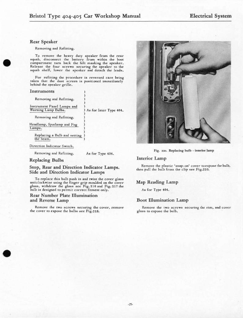
Fig. n o. Replacing bulb · interior lamp
Interior Lamp
Remove the p lastic ' s nap -on' cover weIpoae the bulb, the n pull the bulb from the clip aee F ig.220.
Map Reading Lamp
Aa for Type 404,
Boot I11umination Lamp
Remove the two sc rewa "ecuring the rim, and cover glus to eIpoae the bulb •