Embed Size (px)
Citation preview
from software version V1.33 on BA_2015_1_GB_pCo_DYN
Operating instructions
Electrical switching facility pCo

Page 2 of 31 BA_2015_1_GB_pCo_DYN
TABLE OF CONTENTS
1. Before you start ................................................................... 4 1.1 Brief description ..................................................................... 4 1.2 Using this manual .................................................................. 4
2. pCo integrated controller .................................................... 5 2.1 Design .................................................................................... 5 2.2 Control unit............................................................................. 5 2.3 Controller board ..................................................................... 6 2.4 Terminal board ....................................................................... 6
3. General operation ................................................................ 7 3.1 Elements ................................................................................ 7 3.2 Operating levels ..................................................................... 7 3.2.1 Level 1 (display level) and password entry ............................ 8 3.2.2 Level 2 (parameter level) ....................................................... 9 3.2.3 Level 3 (programming level) ................................................ 10 3.3 Key assignment ................................................................... 11
4. Display level use ................................................................ 12 4.1 Start window ........................................................................ 12 4.2 Status display ...................................................................... 12 4.3 Parameter display ................................................................ 12 4.4 Message list ......................................................................... 12
5. Basic settings ..................................................................... 13 5.1 Starting ................................................................................ 13 5.2 Selecting operating mode .................................................... 13 5.2.1 FIXED PERIOD mode .......................................................... 13 5.2.2 SINGLE LINE mode ............................................................. 13 5.2.3 PROGRESSIVE mode ......................................................... 13 5.2.4 SPRAY LUBRICATION mode .............................................. 13 5.2.5 SKYJET mode (Air-Oil lubrication) ....................................... 14 5.3 Selecting fill level monitoring ................................................ 14 5.4 Prelubrication setting ........................................................... 14
6. Setting parameters ............................................................ 15 6.1 Starting parameterisation ..................................................... 15 6.2 Selecting operating language .............................................. 15 6.3 Entering system parameters ................................................ 15 6.4 Entering time and date ......................................................... 16
Page 3 of 31 BA_2015_1_GB_pCo_DYN
7. Description of controller functions .................................. 17 7.1 Release ................................................................................ 17 7.2 Reset / Intermediate lubrication / Continuous operation ...... 17 7.3 Fill level monitoring .............................................................. 17 7.3.1 Connections used ................................................................ 17 7.3.2 “No monitoring” setting ......................................................... 17 7.3.3 “EMPTY” setting: EMPTY monitoring without shutdown ...... 17 7.3.4 “EMPTY STOP” setting: EMPTY monitoring with shutdown 18 7.3.5 “EMPTY DELAY” setting: EMPTY monitoring with warning
and delayed shutdown ......................................................... 18 7.4 Prelubrication ....................................................................... 19 7.5 Overpressure monitor .......................................................... 19 7.6 FIXED PERIOD mode.......................................................... 19 7.6.1 Signals used ........................................................................ 19 7.6.2 Parameters .......................................................................... 19 7.6.3 Lubrication cycle process ..................................................... 19 7.6.4 Example ............................................................................... 20 7.7 SINGLE LINE operating mode ............................................. 20 7.7.1 Signals used ........................................................................ 20 7.7.2 Parameters .......................................................................... 20 7.7.3 Lubrication cycle process ..................................................... 20 7.7.4 Pressure monitoring ............................................................. 21 7.7.5 Example ............................................................................... 21 7.8 PROGRESSIVE mode ......................................................... 22 7.8.1 Signals used ........................................................................ 22 7.8.2 Parameters .......................................................................... 22 7.8.3 Lubrication cycle process ..................................................... 22 7.8.4 Overcount monitoring ........................................................... 22 7.8.5 Example ............................................................................... 23 7.9 SPRAY LUBRICATION mode .............................................. 23 7.9.1 Connections used ................................................................ 23 7.9.2 Parameters .......................................................................... 23 7.9.3 Lubrication cycle process ..................................................... 24 7.9.4 Example ............................................................................... 24 7.10 Mode SKYJET ..................................................................... 25 7.10.1 Connections used ................................................................ 25 7.10.2 Parameters .......................................................................... 25 7.10.3 Lubrication cycle process ..................................................... 25 7.10.4 Example ............................................................................... 26
8. Reference data ................................................................... 27 8.1 Electrical connections .......................................................... 27 8.1.1 External connections ............................................................ 27 8.1.2 Internal connections ............................................................. 27 8.2 Troubleshooting ................................................................... 30
Page 4 of 31 BA_2015_1_GB_pCo_DYN
1. Before you start
1.1 Brief description pCo is an integrated compact controller for regulating and monitoring pump lubrication. Five keys and a back-lit two-line LCD display are used for settings and operation; they are accessed by opening the cover on the front of the pump. All lubrication tasks possible on the pump are included in the software. The controller offers a variety of options for exchanging information with customer systems.
1.2 Using this manual The operating manual should be read carefully before you use a pump with integrated pCo controller. Inexperienced users should start with Chapter 2 pCo integrated controller and 3 General operation in order to familiarise themselves with the general design and operation of the system. Chapter 5 Basic settings is important for starting the pump. Operators responsible for correct lubrication in terms of amounts and intervals should pay particular attention to Chapter 6 Setting parameters Operators responsible for monitoring the pump but not making any adjustments will find information on displaying the desired information in Chapter 4 Display level use Generally speaking, details of the different pump functions and their settings can be found in the appropriate sections of Chapter 7 Description of controller functions Information on troubleshooting can be found in Chapter 8 Reference data

Page 5 of 31 BA_2015_1_GB_pCo_DYN
2. pCo integrated controller
2.1 Design The controller consists of the following components: a control unit incorporated in the pump housing a controller board mounted in the pump housing an adapter board mounted in the end cap All components are interconnected by ribbon cables.
2.2 Control unit
LCD display to show status data and setting changes
Control keys for selecting and changing values
Fault indicator flashes red for fault; short flashes if display off
2. pCo integrated controller (cont.)
Page 6 of 31 BA_2015_1_GB_pCo_DYN
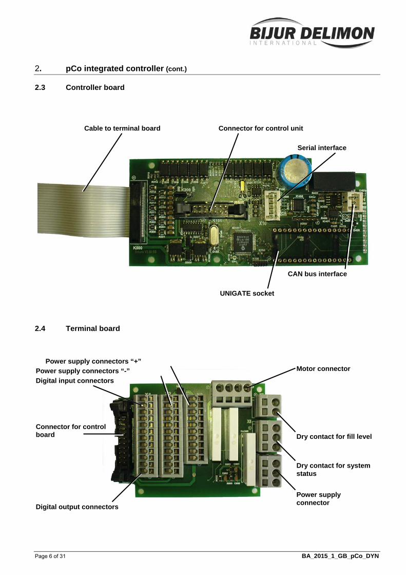
2.3 Controller board
2.4 Terminal board
CAN bus interface
Cable to terminal board Connector for control unit
UNIGATE socket
Serial interface
Power supply connector
Power supply connectors “+”
Connector for control board
Motor connector
Dry contact for system status
Dry contact for fill level
Power supply connectors “-”
Digital input connectors
Digital output connectors
Page 7 of 31 BA_2015_1_GB_pCo_DYN
3. General operation
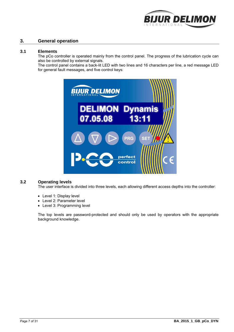
3.1 Elements The pCo controller is operated mainly from the control panel. The progress of the lubrication cycle can also be controlled by external signals. The control panel contains a back-lit LED with two lines and 16 characters per line, a red message LED for general fault messages, and five control keys:
3.2 Operating levels The user interface is divided into three levels, each allowing different access depths into the controller: Level 1: Display level Level 2: Parameter level Level 3: Programming level
The top levels are password-protected and should only be used by operators with the appropriate background knowledge.
3. General operation (cont.)
Page 8 of 31 BA_2015_1_GB_pCo_DYN
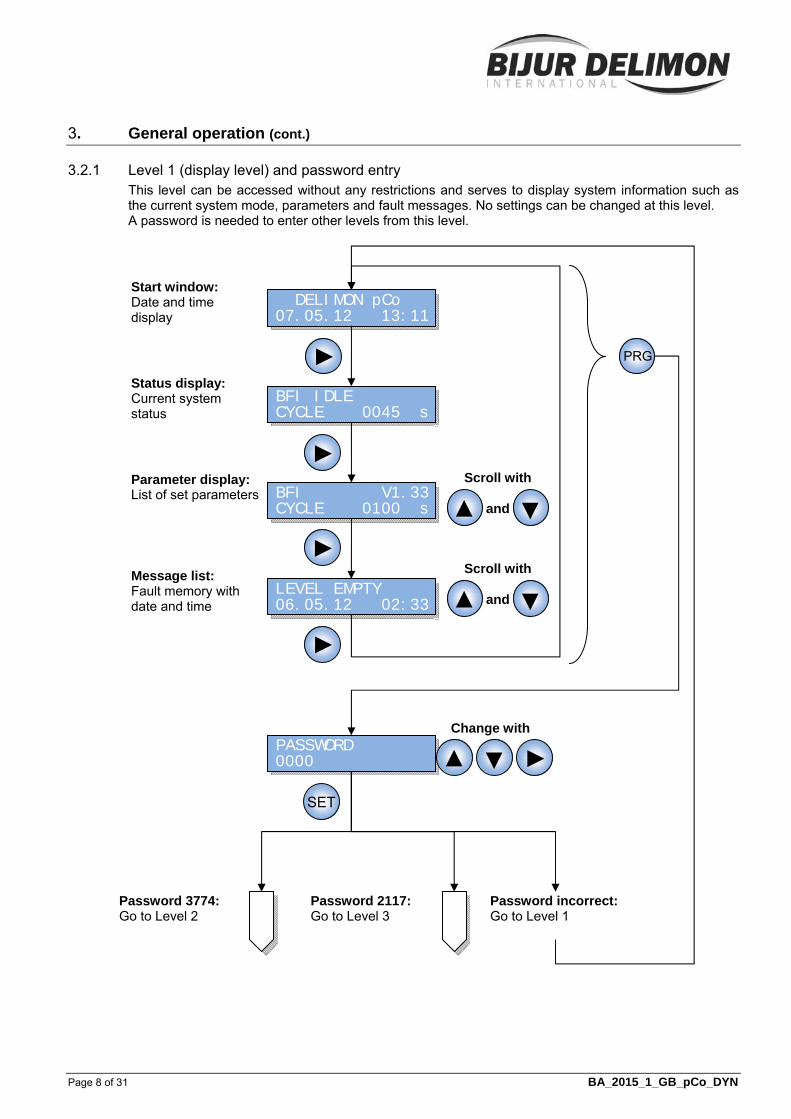
3.2.1 Level 1 (display level) and password entry This level can be accessed without any restrictions and serves to display system information such as the current system mode, parameters and fault messages. No settings can be changed at this level. A password is needed to enter other levels from this level.
DELIMON pCo 07.05.12 13:11
PRG ►
LEVEL EMPTY 06.05.12 02:33
BFI V1.33CYCLE 0100 s
BFI IDLE CYCLE 0045 s
Start window: Date and time display
Status display: Current system status
Parameter display: List of set parameters
Message list: Fault memory with date and time
PASSWORD 0000
Password 3774: Go to Level 2
Password 2117: Go to Level 3
Password incorrect: Go to Level 1
SET
Scroll with
and ▲ ▼
Change with
►
►
►
►▲ ▼
Scroll with
and ▲ ▼
3. General operation (cont.)
Page 9 of 31 BA_2015_1_GB_pCo_DYN
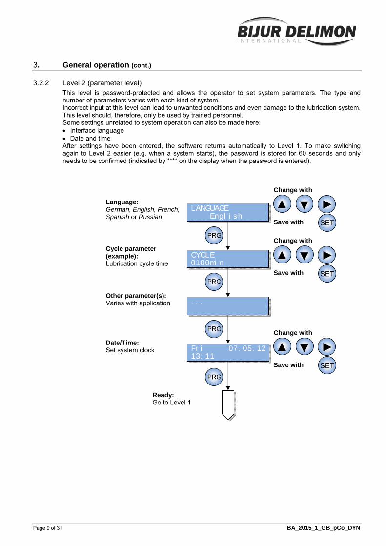
3.2.2 Level 2 (parameter level) This level is password-protected and allows the operator to set system parameters. The type and number of parameters varies with each kind of system. Incorrect input at this level can lead to unwanted conditions and even damage to the lubrication system. This level should, therefore, only be used by trained personnel. Some settings unrelated to system operation can also be made here: Interface language Date and time After settings have been entered, the software returns automatically to Level 1. To make switching again to Level 2 easier (e.g. when a system starts), the password is stored for 60 seconds and only needs to be confirmed (indicated by **** on the display when the password is entered).
CYCLE 0100min
Fri 07.05.1213:11
...
Cycle parameter (example): Lubrication cycle time
Other parameter(s): Varies with application
Date/Time: Set system clock
Ready: Go to Level 1
LANGUAGE English
Language: German, English, French, Spanish or Russian
Change with Save with
Change with Save with
Change with Save with
►▲ ▼
SET
►▲ ▼
SET
►▲ ▼
SET
PRG
PRG
PRG
PRG

3. General operation (cont.)
Page 10 of 31 BA_2015_1_GB_pCo_DYN
3.2.3 Level 3 (programming level) This level is protected by a separate password and allows the controller to be matched to pump use. These settings define the assignment of inputs and outputs to different functions and are, therefore, safety-critical. Incorrect input at this level will prevent proper operation of the pump, so any changes here should only be made by trained personnel.
The operating mode is selected first. This causes the controller to jump to various selection trees and call up only the basic settings for the selected mode. After data has been entered at this level, the software returns to Level 2 automatically so that the system just specified can be parameterised immediately.
Select with
and
OPERATING MODE FIXED PERIOD
p-SWITCHES 1
PRELUBRICATION NO
LEVEL OPTION NONE
- FIXED PERIOD Q1 - SINGLE LINE I4, Q1 - PROGRESSIVE I4, Q1 - SPRAY LUBRIC. I4, I5, Q1, Q4 - SKYJET I4, Q1, Q4
- 1 - 2 I5
OVERCOUNT MONIT.NO
- 1 - 2 I5
- NO - W/O DELAY - WITH DELAY
- NONE - EMPTY I3 - EMPTY STOP I3 - EMPTY DELAY I3
PR
OG
R.
Ready: Go to Level 2
- no - yes
From password entry
MONIT. DIVIDERS 1
SIN
GLE
LI
NE
FIX
ED
P
ER
IOD
SP
RA
Y
LUB
RIC
.
▲ ▼
SET
SET
SET
SET
SETSET
TYPE OF MONITOR PRESSURE SWITCH
- PRESSURE SWITCH - 1 FLOW MONIT. I5 - 2 FLOW MONIT. I5, I6, I7
SK
YJE
T
SET

3. General operation (cont.)
Page 11 of 31 BA_2015_1_GB_pCo_DYN
3.3 Key assignment Key functions depend on the particular situation: Level 1 ▲▼ : scroll through the stored data (e.g. fault messages) ► : change to the next display window PRG : change to password entry SET : short press (<1 s) acknowledge queued fault messages long press (>1 s) acknowledge and start intermediate lubrication Level 2 ▲▼ : change the value at the current cursor position ► : move the cursor to the next changeable position PRG : change to the next settings window SET : store the changes to the current settings window
Level 3 ▲▼ : scroll through selection options ► : not assigned PRG : not assigned SET : accept selection and jump to next option Password entry ▲▼ : change the value at the current cursor position ► : move the cursor to the next position PRG : not assigned SET : submit input (password is checked)
Warning: If you do not press SET, the changes will not be saved; if a value has been changed but not saved, an asterisk (*) will appear in the lower right of the screen.
Page 12 of 31 BA_2015_1_GB_pCo_DYN
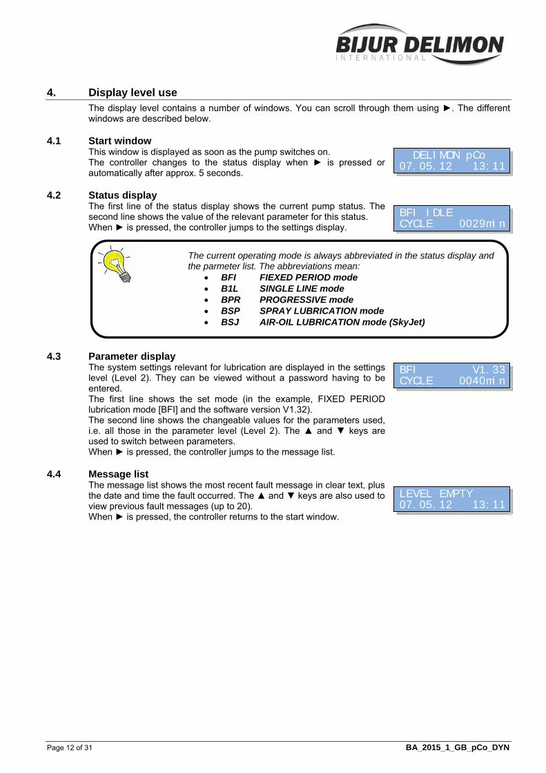
4. Display level use The display level contains a number of windows. You can scroll through them using ►. The different windows are described below.
4.1 Start window This window is displayed as soon as the pump switches on. The controller changes to the status display when ► is pressed or automatically after approx. 5 seconds.
4.2 Status display The first line of the status display shows the current pump status. The second line shows the value of the relevant parameter for this status. When ► is pressed, the controller jumps to the settings display.
4.3 Parameter display The system settings relevant for lubrication are displayed in the settings level (Level 2). They can be viewed without a password having to be entered. The first line shows the set mode (in the example, FIXED PERIOD lubrication mode [BFI] and the software version V1.32). The second line shows the changeable values for the parameters used, i.e. all those in the parameter level (Level 2). The ▲ and ▼ keys are used to switch between parameters. When ► is pressed, the controller jumps to the message list.
4.4 Message list The message list shows the most recent fault message in clear text, plus the date and time the fault occurred. The ▲ and ▼ keys are also used to view previous fault messages (up to 20). When ► is pressed, the controller returns to the start window.
DELIMON pCo 07.05.12 13:11
BFI IDLE CYCLE 0029min
BFI V1.33CYCLE 0040min
LEVEL EMPTY 07.05.12 13:11
The current operating mode is always abbreviated in the status display and the parmeter list. The abbreviations mean:
BFI FIEXED PERIOD mode B1L SINGLE LINE mode BPR PROGRESSIVE mode BSP SPRAY LUBRICATION mode BSJ AIR-OIL LUBRICATION mode (SkyJet)
Page 13 of 31 BA_2015_1_GB_pCo_DYN
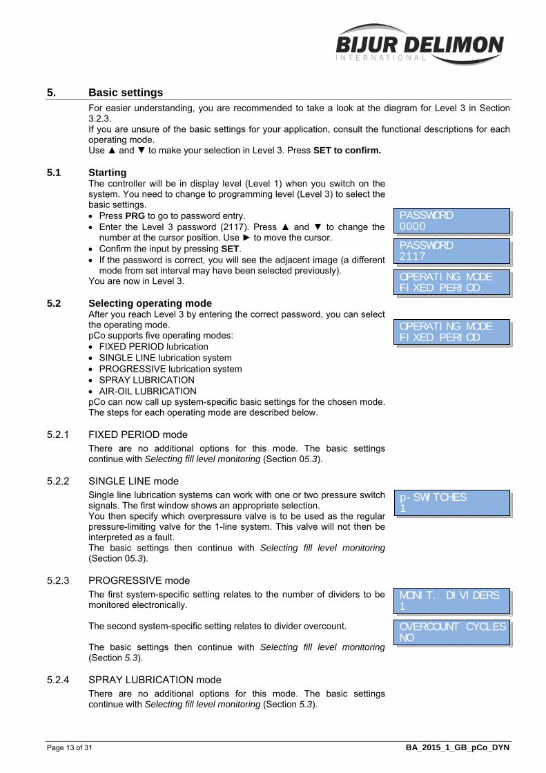
5. Basic settings For easier understanding, you are recommended to take a look at the diagram for Level 3 in Section 3.2.3. If you are unsure of the basic settings for your application, consult the functional descriptions for each operating mode. Use ▲ and ▼ to make your selection in Level 3. Press SET to confirm.
5.1 Starting The controller will be in display level (Level 1) when you switch on the system. You need to change to programming level (Level 3) to select the basic settings. Press PRG to go to password entry. Enter the Level 3 password (2117). Press ▲ and ▼ to change the
number at the cursor position. Use ► to move the cursor. Confirm the input by pressing SET. If the password is correct, you will see the adjacent image (a different
mode from set interval may have been selected previously). You are now in Level 3.
5.2 Selecting operating mode After you reach Level 3 by entering the correct password, you can select the operating mode. pCo supports five operating modes: FIXED PERIOD lubrication SINGLE LINE lubrication system PROGRESSIVE lubrication system SPRAY LUBRICATION AIR-OIL LUBRICATION pCo can now call up system-specific basic settings for the chosen mode. The steps for each operating mode are described below.
5.2.1 FIXED PERIOD mode There are no additional options for this mode. The basic settings continue with Selecting fill level monitoring (Section 05.3).
5.2.2 SINGLE LINE mode Single line lubrication systems can work with one or two pressure switch signals. The first window shows an appropriate selection. You then specify which overpressure valve is to be used as the regular pressure-limiting valve for the 1-line system. This valve will not then be interpreted as a fault. The basic settings then continue with Selecting fill level monitoring (Section 05.3).
5.2.3 PROGRESSIVE mode The first system-specific setting relates to the number of dividers to be monitored electronically. The second system-specific setting relates to divider overcount. The basic settings then continue with Selecting fill level monitoring (Section 5.3).
5.2.4 SPRAY LUBRICATION mode There are no additional options for this mode. The basic settings continue with Selecting fill level monitoring (Section 5.3).
OVERCOUNT CYCLESNO
PASSWORD 0000
PASSWORD 2117
OPERATING MODE FIXED PERIOD
OPERATING MODE FIXED PERIOD
p-SWITCHES 1
MONIT. DIVIDERS 1
5. Basic settings (cont.)
Page 14 of 31 BA_2015_1_GB_pCo_DYN
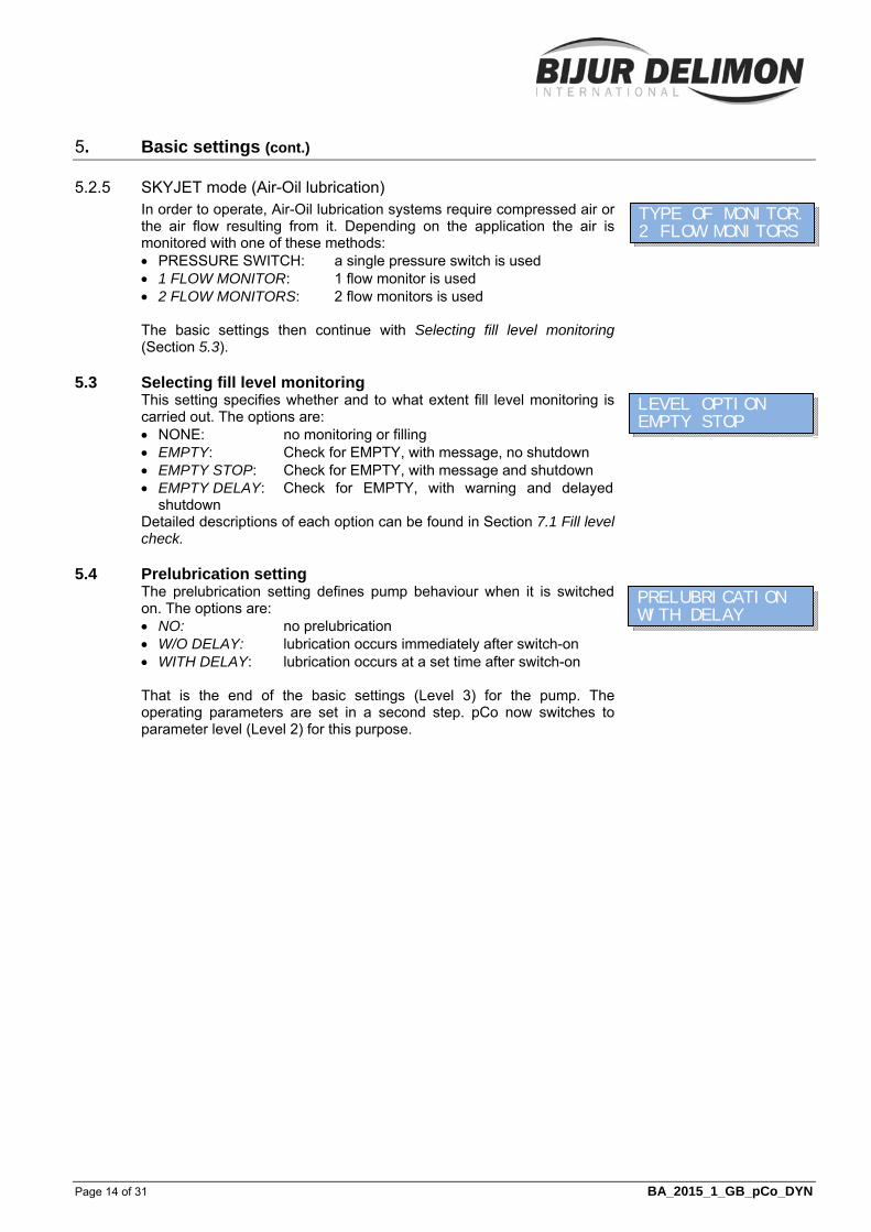
5.2.5 SKYJET mode (Air-Oil lubrication) In order to operate, Air-Oil lubrication systems require compressed air or the air flow resulting from it. Depending on the application the air is monitored with one of these methods: PRESSURE SWITCH: a single pressure switch is used 1 FLOW MONITOR: 1 flow monitor is used 2 FLOW MONITORS: 2 flow monitors is used The basic settings then continue with Selecting fill level monitoring (Section 5.3).
5.3 Selecting fill level monitoring This setting specifies whether and to what extent fill level monitoring is carried out. The options are: NONE: no monitoring or filling EMPTY: Check for EMPTY, with message, no shutdown EMPTY STOP: Check for EMPTY, with message and shutdown EMPTY DELAY: Check for EMPTY, with warning and delayed
shutdown Detailed descriptions of each option can be found in Section 7.1 Fill level check.
5.4 Prelubrication setting The prelubrication setting defines pump behaviour when it is switched on. The options are: NO: no prelubrication W/O DELAY: lubrication occurs immediately after switch-on WITH DELAY: lubrication occurs at a set time after switch-on That is the end of the basic settings (Level 3) for the pump. The operating parameters are set in a second step. pCo now switches to parameter level (Level 2) for this purpose.
LEVEL OPTION EMPTY STOP
PRELUBRICATION WITH DELAY
TYPE OF MONITOR.2 FLOW MONITORS

Page 15 of 31 BA_2015_1_GB_pCo_DYN
6. Setting parameters For easier understanding, you are recommended to take a look at the diagram for Level 2 in Section 3.2.2. If you are unsure of the basic settings for the parameter, consult the functional descriptions for each operating mode.
6.1 Starting parameterisation Proceed as follows to start parameterisation from display level (Level 1): Press PRG to go to password entry. Enter the Level 2 password (3774). Press ▲ and ▼ to change the
number at the cursor position. Use ► to move the cursor. Confirm the input by pressing SET. If the password is correct, you will now see the display on the right. You are now in Level 2.
6.2 Selecting operating language The operating language is set in the first parameterisation window. The options are: German English French Spanish Russian The setting applies to all text shown on the display.
6.3 Entering system parameters The parameters derived from the basic settings are specified in the subsequent windows. The type and number of parameters vary considerably, depending on the operating mode and options. The descriptions for each operating mode include a list of the parameters used, with explanations and principles of operation. This section will be limited to explaining how the parameters are set. The setting window for a parameter contains the following elements: Parameter name Parameter value Unit (not always present) The following elements can be set: Parameter value: all digits including leading zeros can be used; the
setting range may be limited under some conditions Units: the unit can be selected for most parameters (e.g. SEC, MIN,
etc.)
Remember that the content at parameter level depends on the settings at programming level (Level 3). You should start with parameterisation only after the basic settings have been defined.
After the basic settings have been defined, the controller returns automatically from Level 3 to Level 2. No password is needed in this case.
PASSWORD 0000
PASSWORD 3774
LANGUAGE English
LANGUAGE English
{Parameter name}{value} {unit}

6. Setting parameters (cont.)
Page 16 of 31 BA_2015_1_GB_pCo_DYN
Example: The figure on the right shows the parameter Cycle, common to all systems. The value can be set from 1 to 9999. The unit can be set to: IMP: pulses s: seconds min. minutes h: hours Press ▲ and ▼ to change the value at the cursor position. Use ► to move the cursor. Press SET to confirm. Press PRG to jump to the next parameter. If PRG is pressed without pressing SET after the previous entry, any changes will be lost.
6.4 Entering time and date After all parameters have been entered or confirmed, a window appears for entering the date and time. Press ▲ and ▼ to change the value at the cursor position. Use ► to move the cursor. Press SET to confirm. Press PRG to jump to the next window. If PRG is pressed without pressing SET after the previous entry, any changes will be lost.
Cycle 0100s
Mon 07.05.1213:11
Page 17 of 31 BA_2015_1_GB_pCo_DYN
7. Description of controller functions Some pump functions do not depend on the selected operating mode. These will be described first. They are followed by descriptions of each operating mode.
7.1 Release The pump can be controlled via an external release signal, i.e. the set lubrication cycle will run once the release signal is active. This dependency can be circumvented by bridging the signal to the controller’s adapter board. See wiring diagram for details.
7.2 Reset / Intermediate lubrication / Continuous operation Fault messages in the controller must usually be acknowledged. To do so, press the SET key on the display briefly (<1 s). A longer press (>1 s) will also acknowledge existing fault messages, but will also initiate intermediate lubrication. An external signal can also be used in the same way as pressing the key (see wiring diagram for details). A special case is the continuous signal to the external controller input, which switches the pump to continuous operation.
7.3 Fill level monitoring
7.3.1 Connections used The pump usually has a fill level switch which indicates when the level is on EMPTY. This is connected internally to digital input I3. Depending on the setting, the status of the switch affects operation of the pump and message outputs Q2 and Q3, and/or triggers a fault message.
7.3.2 “No monitoring” setting This setting means that the pump controller does not monitor the fill level. This must then be done manually.
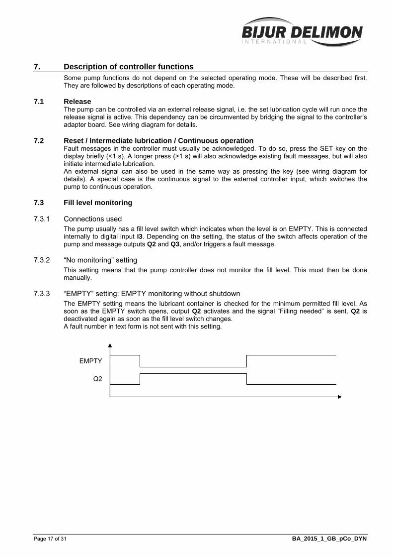
7.3.3 “EMPTY” setting: EMPTY monitoring without shutdown The EMPTY setting means the lubricant container is checked for the minimum permitted fill level. As soon as the EMPTY switch opens, output Q2 activates and the signal “Filling needed” is sent. Q2 is deactivated again as soon as the fill level switch changes. A fault number in text form is not sent with this setting.
EMPTY
Q2
7. Description of controller functions (Fortsetzung)
Page 18 of 31 BA_2015_1_GB_pCo_DYN
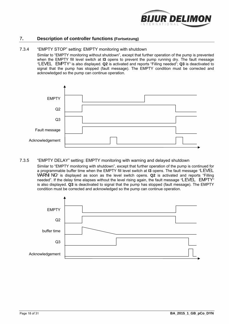
7.3.4 “EMPTY STOP” setting: EMPTY monitoring with shutdown Similar to “EMPTY monitoring without shutdown”, except that further operation of the pump is prevented when the EMPTY fill level switch at I3 opens to prevent the pump running dry. The fault message “LEVEL EMPTY” is also displayed. Q2 is activated and reports “Filling needed”; Q3 is deactivated to signal that the pump has stopped (fault message). The EMPTY condition must be corrected and acknowledged so the pump can continue operation.
7.3.5 “EMPTY DELAY” setting: EMPTY monitoring with warning and delayed shutdown Similar to “EMPTY monitoring with shutdown”, except that further operation of the pump is continued for a programmable buffer time when the EMPTY fill level switch at I3 opens. The fault message “LEVEL WARNING” is displayed as soon as the level switch opens. Q2 is activated and reports “Filling needed”. If the delay time elapses without the level rising again, the fault message “LEVEL EMPTY” is also displayed. Q3 is deactivated to signal that the pump has stopped (fault message). The EMPTY condition must be corrected and acknowledged so the pump can continue operation.
EMPTY
Q3
Fault message
Acknowledgement
Q2
EMPTY
Q2
Q3
buffer time
Acknowledgement

7. Description of controller functions (Fortsetzung)
Page 19 of 31 BA_2015_1_GB_pCo_DYN
7.4 Prelubrication The “Prelubrication” option defines controller behaviour when it is switched on. No prelubrication: The controller has stored the status the last time
the pump was switched off and sets the lubrication cycle to the known value
Prelubrication without delay: When the pump is switched on, the controller starts a lubrication process regardless of the status of the pump the last time it was switched off.
Prelubrication with delay: When the pump is switched on, the “power-on delay” time runs in the controller; initial lubrication starts when this is complete.
7.5 Overpressure monitor Controller inputs I6 and I7 are reserved for connecting electrically monitored overpressure valves. A signal to one of these inputs results in a corresponding fault message. A special case is SINGLE LINE mode, where one of the overpressure valves is used as a regular pressure limiting valve and is therefore not assessed as a fault. This assignment is specified in the basic settings. Details on connecting the monitor can be found in the schematics.
7.6 FIXED PERIOD mode
7.6.1 Signals used The following signals are used for the FIXED PERIOD operating mode. Signal Connection Switch typeRelease Signal connector NO contact Switch on pump internal NO contact
7.6.2 Parameters Cycle time: The period from one lubrication start to the next; the cycle can be specified in
seconds, minutes and hours (s, min, h), in which case a timer operates until the release signal is received; if the signal is interrupted, the timer pauses and restarts at the same point the signal resumes. The cycle can also be specified in pulses (IMP); release signal pulses are then counted and a timer is not used.
Lube ON-time: Switch-on period for lubrication pump; the time can be specified in s, min or h.
7.6.3 Lubrication cycle process
The pump is switched on; ON-time and Cycle time are started simultaneously.
The pump supplies lubricant. The pump is switched off as soon as the ON-time finishes. The cycle time counts down while the release is received. A new lubrication process starts when the cycle time ends.
BFI RUNNING ON_TIME 0017 s
BFI IDLE CYCLE 0030min
7. Description of controller functions (Fortsetzung)
Page 20 of 31 BA_2015_1_GB_pCo_DYN
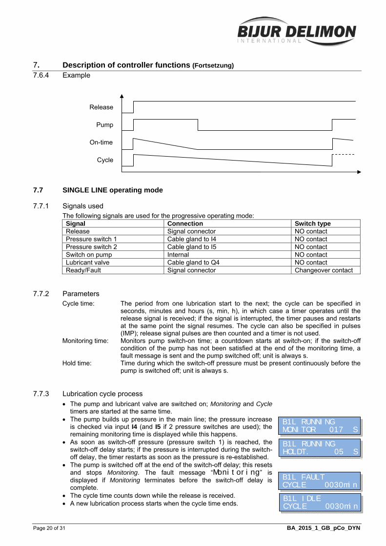
7.6.4 Example
7.7 SINGLE LINE operating mode
7.7.1 Signals used The following signals are used for the progressive operating mode: Signal Connection Switch type Release Signal connector NO contact Pressure switch 1 Cable gland to I4 NO contact Pressure switch 2 Cable gland to I5 NO contact Switch on pump Internal NO contact Lubricant valve Cable gland to Q4 NO contact Ready/Fault Signal connector Changeover contact
7.7.2 Parameters Cycle time: The period from one lubrication start to the next; the cycle can be specified in
seconds, minutes and hours (s, min, h), in which case a timer operates until the release signal is received; if the signal is interrupted, the timer pauses and restarts at the same point the signal resumes. The cycle can also be specified in pulses (IMP); release signal pulses are then counted and a timer is not used.
Monitoring time: Monitors pump switch-on time; a countdown starts at switch-on; if the switch-off condition of the pump has not been satisfied at the end of the monitoring time, a fault message is sent and the pump switched off; unit is always s.
Hold time: Time during which the switch-off pressure must be present continuously before the pump is switched off; unit is always s.
7.7.3 Lubrication cycle process
The pump and lubricant valve are switched on; Monitoring and Cycle timers are started at the same time.
The pump builds up pressure in the main line; the pressure increase is checked via input I4 (and I5 if 2 pressure switches are used); the remaining monitoring time is displayed while this happens.
As soon as switch-off pressure (pressure switch 1) is reached, the switch-off delay starts; if the pressure is interrupted during the switch-off delay, the timer restarts as soon as the pressure is re-established.
The pump is switched off at the end of the switch-off delay; this resets and stops Monitoring. The fault message “Monitoring” is displayed if Monitoring terminates before the switch-off delay is complete.
The cycle time counts down while the release is received. A new lubrication process starts when the cycle time ends.
Release
Pump
Cycle
On-time
B1L RUNNING MONITOR 017 S
B1L RUNNING HOLDT. 05 S
B1L FAULT CYCLE 0030min
B1L IDLE CYCLE 0030min
7. Description of controller functions (Fortsetzung)
Page 21 of 31 BA_2015_1_GB_pCo_DYN
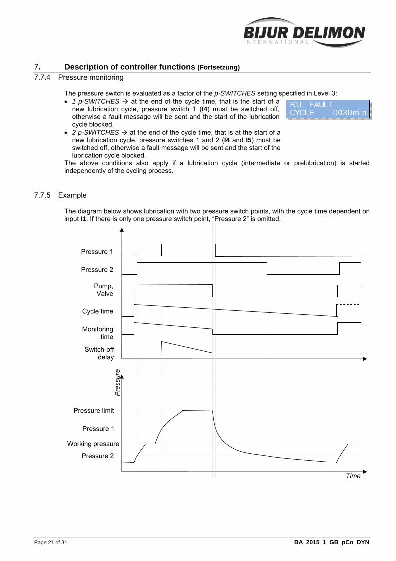
7.7.4 Pressure monitoring
The pressure switch is evaluated as a factor of the p-SWITCHES setting specified in Level 3: 1 p-SWITCHES at the end of the cycle time, that is the start of a
new lubrication cycle, pressure switch 1 (I4) must be switched off, otherwise a fault message will be sent and the start of the lubrication cycle blocked.
2 p-SWITCHES at the end of the cycle time, that is at the start of a new lubrication cycle, pressure switches 1 and 2 (I4 and I5) must be switched off, otherwise a fault message will be sent and the start of the lubrication cycle blocked.
The above conditions also apply if a lubrication cycle (intermediate or prelubrication) is started independently of the cycling process.
7.7.5 Example
The diagram below shows lubrication with two pressure switch points, with the cycle time dependent on input I1. If there is only one pressure switch point, “Pressure 2” is omitted.
Pressure 1
Pressure 2
Pump, Valve
Cycle time
Monitoring time
Pre
ssur
e
Switch-off delay
Pressure limit
Pressure 1
Pressure 2
Working pressure
Time
B1L FAULT CYCLE 0030min

7. Description of controller functions (Fortsetzung)
Page 22 of 31 BA_2015_1_GB_pCo_DYN
7.8 PROGRESSIVE mode
7.8.1 Signals used The following signals are used for the PROGRESSIVE operating mode: Signal Connection Switch type Release Signal connector NO contact Divider monitor 1 Cable gland to I4 NO contact Divider monitor 2 Cable gland to I5 NO contact Switch on pump Internal NO contact Ready/Fault Signal connector Changeover contact
7.8.2 Parameters Cycle time: The period from one lubrication start to the next; the cycle can be specified in
seconds, minutes and hours (s, min, h), in which case a timer operates until the release signal is received; if the signal is interrupted, the timer pauses and restarts at the same point the signal resumes. The cycle can also be specified in pulses (IMP); release signal pulses are then counted and a timer is not used.
Monitoring time: Monitors pump switch-on time; a countdown starts at switch-on; if the switch-off condition of the pump has not been satisfied at the end of the monitoring time, a fault message is sent and the pump switched off; unit is s or min.
Cycles Divider 1: The number of pulses at input I4; unit is always IMP; the pump is switched off again when the entered number of pulses has counted down.
Cycles Divider 2: The number of pulses at input I5; unit is always IMP; the pump is switched off again when the entered number of pulses has counted down (only with 2 monitored dividers).
7.8.3 Lubrication cycle process
The pump is switched on; Monitoring and Cycle timers are started simultaneously.
The pump supplies lubricant to the dividers (up to 2, 1 per pump element). The divider turns are counted via input I4 (and I5 if 2 dividers). The remaining monitoring time is displayed during this process.
The pump is switched off as soon as all monitored distributors have completed the programmed number of cycles. Monitoring is reset and stopped. The fault message “Monitoring” is displayed if Monitoring terminates before all dividers have completed their turns.
The cycle time counts down while the release is received. If overcount monitoring is on, any divider turns are counted.
A new lubrication process starts when the cycle time ends.
7.8.4 Overcount monitoring If overcount monitoring is on, any divider turns are counted during the pause. Up to 3 turns are permitted, but any further turns during the pause activate the fault message “DIVIDER OVERCNT”.
BPR RUNNING MONITOR 017 S
BPR FAULT MONITOR 000 S
BPR IDLE CYCLE 0030min
BPR FAULT CYCLE 0031min

7. Description of controller functions (Fortsetzung)
Page 23 of 31 BA_2015_1_GB_pCo_DYN
7.8.5 Example The diagram below shows the process for a system with 2 monitored dividers. Both are programmed for 4 turns. The pump is switched off when the last divider (here, distributor 2) has completed its turns.
7.9 SPRAY LUBRICATION mode
7.9.1 Connections used The following signals are used for the progressive operating mode: Signal Connection Switch type Release Signal connector NO contact Divider monitoring Cable gland to I4 NO contact Pressure switch Cable gland to I5 NO contact Switch on pump Internal NO contact Spray air valve Cable gland to Q4 NO contact Ready/Fault Signal connector Changeover contact
7.9.2 Parameters Cycle time: The period from one lubrication start to the next; the cycle can be specified in
seconds, minutes and hours (s, min, h), in which case a timer operates until the release signal is received; if the signal is interrupted, the timer pauses and restarts at the same point the signal resumes. The cycle can also be specified in pulses (IMP); release signal pulses are then counted and a timer is not used.
Monitoring time: Monitors pump switch-on time; a countdown starts at switch-on; if the switch-off condition of the pump has not been satisfied at the end of the monitoring time, a fault message is sent and the pump switched off; unit is s or min.
Cycles Divider 1: The number of pulses at input I4; unit is always IMP; the pump is switched off again when the entered number of pulses has counted down.
Spray time: The spraying duration; unit is always s; after the pump is switched off, output Q4 is switched on for the set period.
Release
Divider 1
Divider 2
Pump
Cycle time
Monitoring
7. Description of controller functions (Fortsetzung)
Page 24 of 31 BA_2015_1_GB_pCo_DYN
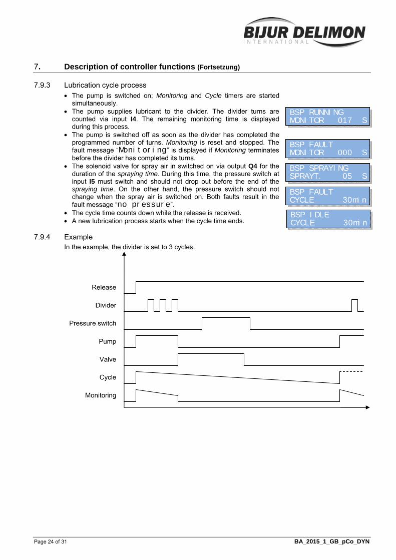
7.9.3 Lubrication cycle process
The pump is switched on; Monitoring and Cycle timers are started simultaneously.
The pump supplies lubricant to the divider. The divider turns are counted via input I4. The remaining monitoring time is displayed during this process.
The pump is switched off as soon as the divider has completed the programmed number of turns. Monitoring is reset and stopped. The fault message “Monitoring” is displayed if Monitoring terminates before the divider has completed its turns.
The solenoid valve for spray air in switched on via output Q4 for the duration of the spraying time. During this time, the pressure switch at input I5 must switch and should not drop out before the end of the spraying time. On the other hand, the pressure switch should not change when the spray air is switched on. Both faults result in the fault message “no pressure”.
The cycle time counts down while the release is received. A new lubrication process starts when the cycle time ends.
7.9.4 Example In the example, the divider is set to 3 cycles.
Release
Divider
Pressure switch
Pump
Cycle
Monitoring
Valve
BSP RUNNING MONITOR 017 S
BSP FAULT MONITOR 000 S
BSP SPRAYING SPRAYT. 05 S
BSP FAULT CYCLE 30min
BSP IDLE CYCLE 30min
7. Description of controller functions (Fortsetzung)
Page 25 of 31 BA_2015_1_GB_pCo_DYN
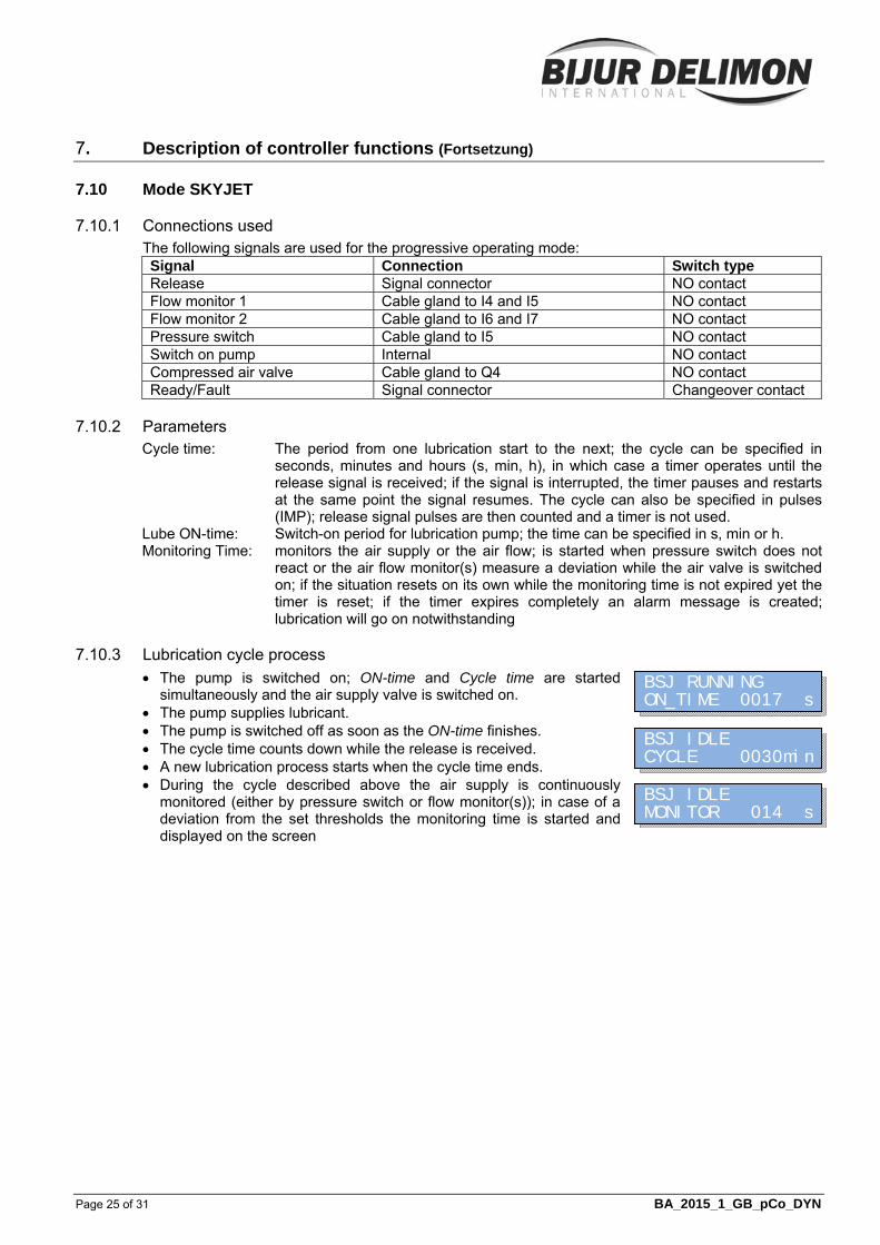
7.10 Mode SKYJET
7.10.1 Connections used The following signals are used for the progressive operating mode: Signal Connection Switch type Release Signal connector NO contact Flow monitor 1 Cable gland to I4 and I5 NO contact Flow monitor 2 Cable gland to I6 and I7 NO contact Pressure switch Cable gland to I5 NO contact Switch on pump Internal NO contact Compressed air valve Cable gland to Q4 NO contact Ready/Fault Signal connector Changeover contact
7.10.2 Parameters Cycle time: The period from one lubrication start to the next; the cycle can be specified in
seconds, minutes and hours (s, min, h), in which case a timer operates until the release signal is received; if the signal is interrupted, the timer pauses and restarts at the same point the signal resumes. The cycle can also be specified in pulses (IMP); release signal pulses are then counted and a timer is not used.
Lube ON-time: Switch-on period for lubrication pump; the time can be specified in s, min or h. Monitoring Time: monitors the air supply or the air flow; is started when pressure switch does not
react or the air flow monitor(s) measure a deviation while the air valve is switched on; if the situation resets on its own while the monitoring time is not expired yet the timer is reset; if the timer expires completely an alarm message is created; lubrication will go on notwithstanding
7.10.3 Lubrication cycle process
The pump is switched on; ON-time and Cycle time are started simultaneously and the air supply valve is switched on.
The pump supplies lubricant. The pump is switched off as soon as the ON-time finishes. The cycle time counts down while the release is received. A new lubrication process starts when the cycle time ends. During the cycle described above the air supply is continuously
monitored (either by pressure switch or flow monitor(s)); in case of a deviation from the set thresholds the monitoring time is started and displayed on the screen
BSJ RUNNING ON_TIME 0017 s
BSJ IDLE CYCLE 0030min
BSJ IDLE MONITOR 014 s
7. Description of controller functions (Fortsetzung)
Page 26 of 31 BA_2015_1_GB_pCo_DYN
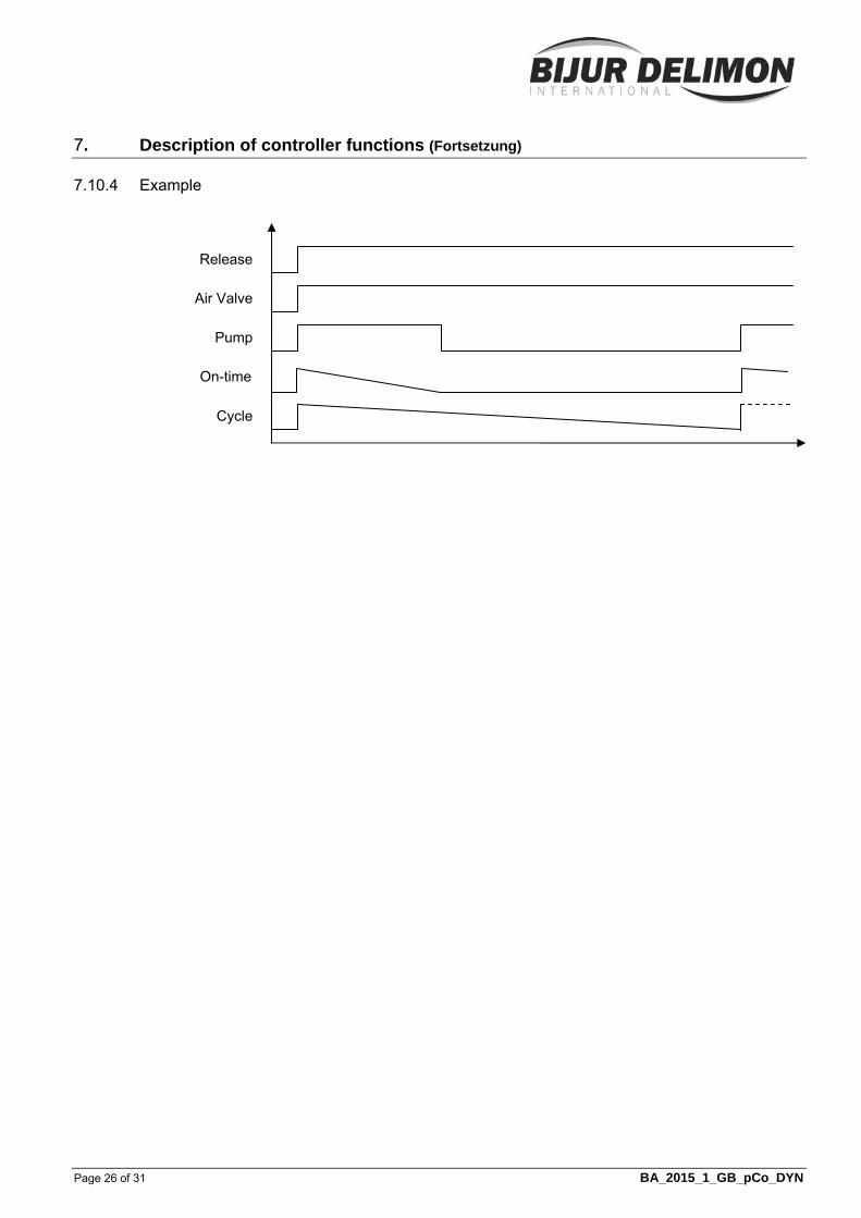
7.10.4 Example
Air Valve
Pump
Cycle
On-time
Release
Page 27 of 31 BA_2015_1_GB_pCo_DYN
8. Reference data
8.1 Electrical connections
8.1.1 External connections For information on the electrical plugs please refer tot he pump’s manual. All available versions are described there.
8.1.2 Internal connections Depending on the tyoe of lubrication system to be controlled, there can be several external electrical devices used, e.g. proximity switches, pressure switches, solenoid valves. In many cases these are pre-wired at delivery, especially if the devices are mounted on the pump itself or when the pump is delivered as part of a more complex unit. Nevertheless there are cases when the wiring of the devices needs to be done by the customer. The following pictures show the connection of all devices used in the standard.
8.1.2.1 FIXED PERIOD mode In this mode there are no external devices.
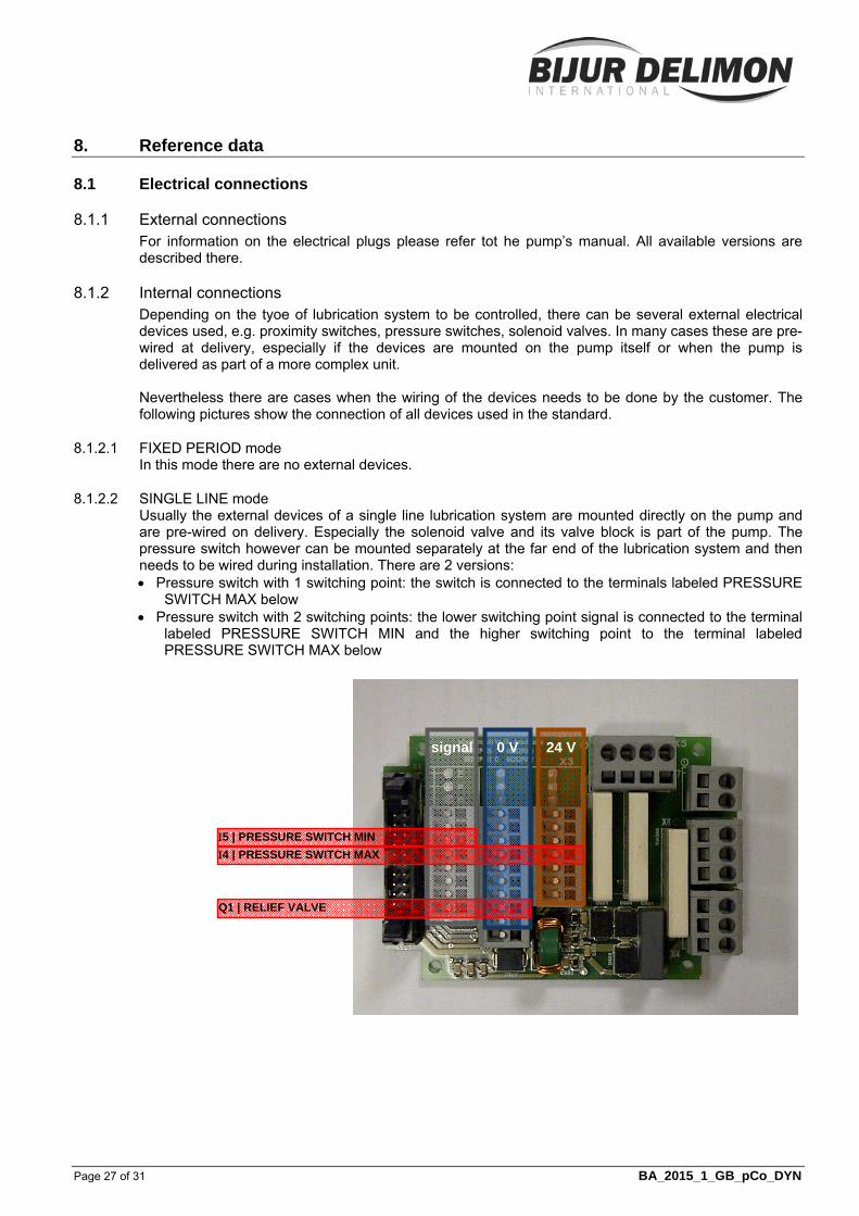
8.1.2.2 SINGLE LINE mode Usually the external devices of a single line lubrication system are mounted directly on the pump and are pre-wired on delivery. Especially the solenoid valve and its valve block is part of the pump. The pressure switch however can be mounted separately at the far end of the lubrication system and then needs to be wired during installation. There are 2 versions: Pressure switch with 1 switching point: the switch is connected to the terminals labeled PRESSURE
SWITCH MAX below Pressure switch with 2 switching points: the lower switching point signal is connected to the terminal
labeled PRESSURE SWITCH MIN and the higher switching point to the terminal labeled PRESSURE SWITCH MAX below
signal 0 V 24 V
Q1 | RELIEF VALVE
4 | PRESSURE SWITCH MAX
5 | PRESSURE SWITCH MIN

8. Reference data (Fortsetzung)
Page 28 of 31 BA_2015_1_GB_pCo_DYN
8.1.2.3 PROGRESSIVE mode In many cases the main divider of a progressive lubrication system is mounted on the pump and the proximity switch is pre-wired on delivery. But if the divider is mounted remotely or if there are 2 monitored dividers wiring needs to be done during installation on site.
8.1.2.4 SPRAY LUBRICATION mode The progressive divider may be directly attached to the pump on delivery. In this case the monitoring switch is pre-wired on delivery. The divider may also be mounted remotely and must then be wired on installation, as well as the air valve and the pressure switch.
signal 0 V 24 V
4 | DIVIDER MONITORING
5 | AIR PRESSURE SWITCH
Q1 | SOLENOID VALVE AIR
signal 0 V 24 V
4 | DIVIDER MONITORING 1
5 | DIVIDER MONITORING 2
8. Reference data (Fortsetzung)
Page 29 of 31 BA_2015_1_GB_pCo_DYN
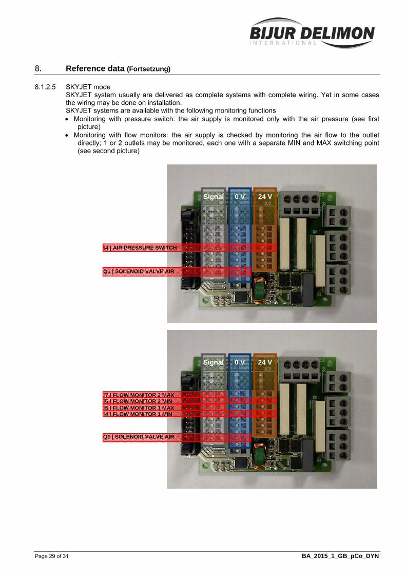
8.1.2.5 SKYJET mode SKYJET system usually are delivered as complete systems with complete wiring. Yet in some cases the wiring may be done on installation. SKYJET systems are available with the following monitoring functions Monitoring with pressure switch: the air supply is monitored only with the air pressure (see first
picture) Monitoring with flow monitors: the air supply is checked by monitoring the air flow to the outlet
directly; 1 or 2 outlets may be monitored, each one with a separate MIN and MAX switching point (see second picture)
Signal 0 V 24 V
4 | FLOW MONITOR 1 MIN
Q1 | SOLENOID VALVE AIR
5 | FLOW MONITOR 1 MAX6 | FLOW MONITOR 2 MIN7 | FLOW MONITOR 2 MAX
Signal 0 V 24 V
4 | AIR PRESSURE SWITCH
Q1 | SOLENOID VALVE AIR
8. Reference data (Fortsetzung)
Page 30 of 31 BA_2015_1_GB_pCo_DYN
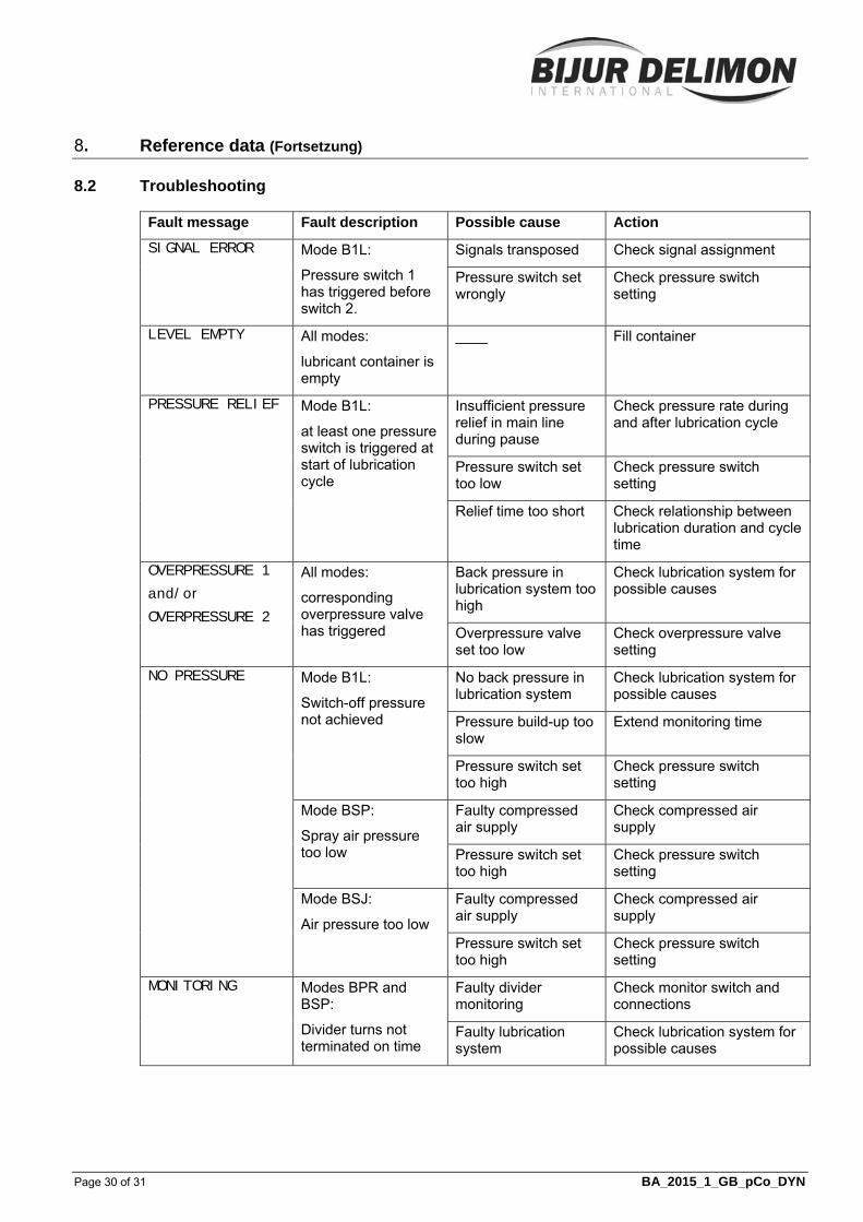
8.2 Troubleshooting
Fault message Fault description Possible cause Action
SIGNAL ERROR Mode B1L:
Pressure switch 1 has triggered before switch 2.
Signals transposed Check signal assignment
Pressure switch set wrongly
Check pressure switch setting
LEVEL EMPTY All modes:
lubricant container is empty
____ Fill container
PRESSURE RELIEF Mode B1L:
at least one pressure switch is triggered at start of lubrication cycle
Insufficient pressure relief in main line during pause
Check pressure rate during and after lubrication cycle
Pressure switch set too low
Check pressure switch setting
Relief time too short Check relationship between lubrication duration and cycle time
OVERPRESSURE 1
and/or
OVERPRESSURE 2
All modes:
corresponding overpressure valve has triggered
Back pressure in lubrication system too high
Check lubrication system for possible causes
Overpressure valve set too low
Check overpressure valve setting
NO PRESSURE Mode B1L:
Switch-off pressure not achieved
No back pressure in lubrication system
Check lubrication system for possible causes
Pressure build-up too slow
Extend monitoring time
Pressure switch set too high
Check pressure switch setting
Mode BSP:
Spray air pressure too low
Faulty compressed air supply
Check compressed air supply
Pressure switch set too high
Check pressure switch setting
Mode BSJ:
Air pressure too low
Faulty compressed air supply
Check compressed air supply
Pressure switch set too high
Check pressure switch setting
MONITORING Modes BPR and BSP:
Divider turns not terminated on time
Faulty divider monitoring
Check monitor switch and connections
Faulty lubrication system
Check lubrication system for possible causes

8. Reference data (Fortsetzung)
Page 31 of 31 BA_2015_1_GB_pCo_DYN
Fault message Fault description Possible cause Action
DIVIDER OVERCNT Mode BPR:
one or more divider(s) did more than 3 turns during pause time
Faulty divider monitoring
Check monitor switch and connections
Pump motor did not stop during pause time
Check function of pump motor
Q1 < MIN
(Q2 < MIN)
Mode BSJ
Air flow on Q1 (2) is too low
Faulty compressed air supply
Check compressed air supply
Quick coupling not connected
Check quick coupling
Flow monitor set too high
Check Flow monitor setting
Q1 > MAX
(Q2 > MAX)
Mode BSJ
Air flow on Q1 (2) is too high
Open end line or considerable leakage in Air-Oil line
Check Air-Oil line
Flow monitor set too low
Check Flow monitor setting