Embed Size (px)
Citation preview

Page 0
ELECTRICAL SMME/EMEWORKS FOR THE
THORNHILL SEWAGEPUMP STATION
PACKAGES:
SEWER PUMP STATION(PACKAGE 1: E4 Transformer
Installation)
PREPARED BY:
SONDEZA AMANZI25 Ray Craib CrescentBeacon BayEast London5241

Page 1
REQUEST FOR QUOTATIONS
A INTRODUCTION
The Thornhill Ministerial Housing Project is an initiative undertaken jointly between ABSA Property
Development, Ndlambe Local Municipality and the Department of Housing, Local Government and
Traditional Affairs. In line with the vision of the ‘Breaking New Ground’ initiative, the project seeks
to provide quality and affordable housing in a development that is mixed mode, and to create a
vibrant and sustainable community.
The Eastern Cape Office of the Premier has made funding available to implement the link
infrastructure required for the development of Phase 1 of the Thornhill Ministerial Housing Project.
The scope of the link infrastructure is as follows:
Package 1: Transformer
o Installation and commissioning of 50kVA transformer, including metering kiosk and
fence.
o The 50kVA,11kV/400V outdoor, plinth mounted transformer is to be installed only
and commissioned only, the transformer will be provided by the Main Contractor and
the plinths cast by others.
o Energizing of MV Network and supply of all Test Certificates.
o Costing for the energizing of the MV Network and provision of all Test Certificates
must be included in the costing.
As part of the main contractor’s obligations, he is contractually required to sub-contract certain of the
works to local SMMEs/EMEs.

Page 2
T1.1: TENDER NOTICE & INVITATION
TENDER NOTICE & INVITATION TO TENDER FOR NDLAMBE SMMESPROJECT NAME: THORNHILL SEWAGE PUMP STATION
Tenders are hereby invited from suitably construction firms for the following:
Project NameNumber of
SMMEsRequired
Scope (Brief)CIDB
Grading
ClosingDate &Time
Transformer Installation (Package 1) 1Install and Commissiontransformer. 1 EP
11 November2021 @ 12h00
Only Tenderers with a Construction Industry Development Board (CIDB) minimum grading as indicated above will be eligible totender.
Tender documents may be downloaded from the Ndlambe Local Municipality website at no cost, from Wednesday 27/10/2021.
Due to Covid 19 regulations NO COMPULSORY Briefing session will be held.
The site of the works is located close to the Thornhill Elevated Reservoir currently under construction.
Bidders should take note of possible questions herewith attached in this advert. For any further clarity, all communications must be inwriting.
Completed tender documents in sealed envelopes clearly written on the outside as per the bid document: e.g., “Tender No: E4Transformer Installation (Package 1)” must be placed in the relevant tender box at Supply Chain offices at No. 44 Campbell Street,Port Alfred by no later than 12:00 on 11 November 2021. Bid opening register will be forwarded to all bidders on the same day andthe opening meeting will conducted through zoom for transparency. Interested bidders who would like to witness the tender openingshould indicate via email and the municipality will forward them the ID for the virtual meeting.
BIDS WILL BE EVALUATED ON THE BASIS OF RESPONSIVENESS FIRST THEN FUNCTIONALITY AND ONLYRESPONSIVE BIDS WILL BE EVALUATED ON PRICE.
Functionality: 100 points, Minimum qualifying points will be 70 for further evaluation.
FUNCTIONALITY POINTS
Experience 40
Bids must submit a Curriculum Vitae of a competent person who will be aforeman/ supervisor for the duration of the contract and must have thefollowing requirements:
Minimum of Six (6) months experience in supervision of thescope of works stipulated in the relevant Bill of Quantities with atleast 3 contact references (Client, Name of the project, Contactname and telephone numbers)
Failure to submit the required documents will score zero (0) points.
40
Locality 60
Bidder residing within Ndlambe municipality: Proof of water/ electrical municipal services bill not older than 3
months.
Unverified documentation will score zero (0) points
60

Page 3
PROSPECTIVE BIDDERS SHALL TAKE NOTE OF THE FOLLOWING BID CONDITIONS:
It should be noted that the 80/20 points system will be applied, 80 being for price and 20 for the B-BBEE status level as defined
in the Preferential Procurement Regulations, 2017.
The award will be made in terms of the Municipality’s Supply Chain Management Policy.
Prices must be valid for at least ninety (90) days from the closing date.
Prices quoted must be firm.
Ndlambe Municipality does not bind itself to accept the lowest bid or any other bid and reserves the right to accept the whole or
part of the bid.
An original tax clearance certificate issued by SARS must accompany all tenders OR a tax reference number and PIN or TCC
number must be provided. Tax status will also be verified against the Central Supplier Database (CSD)
Evidence of registration of company on the Central Supplier Database must be provided (CSD “MAAA” number).
Bidders must complete Council’s Declaration of Interest form (MBD4, MBD8, and MBD 9). Bidders who wish to claim for
preferential points in terms of the Preferential Procurement Regulations, 2017, must submit a completed form MBD 6.1 (included
in the returnable document) as well as a certified copy of the proof of B-BBEE status level of contribution as follows:
In the case of an Affidavit, both the Commissioner of Oaths stamp for the Affidavit itself (the “commissioning”)
AND a “true copy” stamp (which certifies the document as being a true copy of the original) are required i.e. TWO
stamps are required.
In the case of a B-BBEE Certificate, only a “true copy” stamp and signature (which certifies the document as being
an accurate copy) is required i.e. ONE stamp is required.
The abovementioned MBD forms are available for download from: http://www.ndlambe.gov.za/web/MDB-
Documents
A Municipal Billing Clearance Certificate, which covers, if applicable, both the company and its directors, must accompany all
bids (included in the returnable document).
In case of the joint Venture, a memorandum of agreement indicating the level of involvement and responsibilities of each joint
venture partner must be submitted. Individual partners are to comply and submit all relevant documents.
Bids that are late will not be considered, whilst the lowest or only quotation will not necessarily be accepted. Quotations per fax or
E-mail will also not be considered.
Bidders to submit a letter of Good standing from compensation commission within 7 days upon receipt a letter of intent to appoint
Bidders will only be awarded one package under the Thornhill Sewage Pump Station SMME Packages
Bidders must submit a Company Registration Certificate.
It has been determined that, in terms of 2017 PPPFA Regulations 4(1)(a), only tenderers with a minimum B-BBEE Status level of
contribution of 1 (One) may respond to the invitations in respect of All packages as set out in this contract.
Evidence of registration of company on the Central Supplier Database must be provided (CSD “MAAA” number).
Bidders to submit a Programme of Works stipulating the time needed to complete the relevant schedules.
Bidders that have already been appointed for work on the Thornhill Reservoir and Sewer Pumpstation Contract 70/2019 or
Contract 154/2019 will not be eligible to tender for this work.
Enquiries relating to technical matters may be referred to Mr. A Labuschagne (Sondeza Amanzi) on 043 722 1831 or

Page 4
T1.2: TENDER DATA: SPECIAL CONDITIONS OF TENDER
1. DURATION OF CONTRACT
This is a once off contract where the Sub-Contractor shall provide a Programme of Works to
advise on the duration thereof.
2. PAYMENTS
All payments will be made to the Service Provider within thirty (30) days of verification of
an invoice.
3. SERVICE LEVEL AGREEMENT
3.1 A service level agreement will be entered into with the successful bidder.
3.2 Negotiations in respect of the service level agreement must be finalised within fourteen
(14) calendar days of receipt of the letter of acceptance by the successful bidder."
3.3 Service level agreement entered into with the successful bidder will capture the time
frames for performance applying to this contract.
3.4 GCC 2015 Third edition shall be applicable to this Contract.
4. PENALTIES
Penalties shall be applicable to this agreement as per clause 5.13 in the GCC 2015 in the
amount of R900 per calendar day should the SMME not complete the works within the
required time for completion.
5. TERMINATION FOR DEFAULT
After default the following shall apply:
Notice of non – performance/ breach within 7 days of production not being achieved,
14 days to remedy breach,
Termination of contract after 21 days of continued non- performance.
6. PRICE
This Tender shall be a Fixed Price Contract. Contract price adjustment shall not be
applicable to this Tender.
7. BID VALIDITY
This bid shall not be withdrawn during a period of ninety (90) days from the date on which it
is to be lodged and it may be accepted at any time during that period.
Page 5
8. RETURNABLE DOCUMENTS
The issued documents must be returned in the form and order in which they were issued to
assist Sondeza Amanzi to expedite adjudication of the bids. Sondeza Amanzi reserves the
right to disqualify a bid in the event that the bidder does not fully comply with this provision.
9. MANDATORY OBJECTION PERIOD
All administrative actions and decisions taken by Sondeza Amanzi through its officials may
become subject to an objections and appeals process. As such, in terms of Section 62 of the
Municipal Systems Act 32 of 2000, a period of Fourteen (14) days will be set aside to allow
for the submission of appeals against the award/process of making the award to a particular
bidder by any interested party. Except in scenarios where the decision of a duly appointed
panel sets aside the appointment of the successful bidder as service provider of this contract,
the appointment will then be confirmed by Sondeza Amanzi in writing.
10. THIS BID DOCUMENT WILL ONLY BE ACCEPTED IF IT IS COMPLETED IN
BLACK INK.

Page 6
PART T2: RETURNABLE DOCUMENTS
TABLE OF CONTENTS
T2.1 List of Returnable Documents 7
T2.2 Returnable Schedules 8-15

7
T2.1 : LIST OF RETURNABLE DOCUMENTS
The following documents are to be completed and returned as they constitute the tender.
Whilst many of the returnable are required for the purpose of evaluating the tenders, some
will form part of the subsequent contract, as they form the basis of the tender offer. For
this reason, it is very important that tenderers return all information requested.
1.RETURNABLE SCHEDULES REQUIRED FOR TENDER EVALUATION PURPOSES
(included hereafter for completion)
Addendum A Resolution of Authority to Sign Documents
Addendum B Tax Clearance Certificate
Addendum C Certificate of Independent Bid Determination: MBD 9
Addendum D Preference Points Claim Form: MBD 6.1 as well as original Certified Copy
of B – BBEE status level contributor or Affidavit).
Addendum E Declaration of Interest: MBD 4
Addendum F Programme of Works
Addendum G Declaration of Bidders past Supply Chain Management practices: MDB 8
Schedule : 1A Municipal Billing Certificate
Schedule : 1B Centralized Supply Database (CSD)

8
ADDENDUM A: RESOLUTION OF AUTHORITY TO SIGNDOCUMENTS.
RESOLUTION OF AUTHORITY TO SIGN DOCUMENTS
(I/We)*, the undersigned, am/are* duly authorized to sign the Tender Form for this
contract on behalf ……………………………………………………………………....
in accordance with a directors resolution taken on ……………….(date) by the
directors of ………………………………………………….(company name)
registered with the registrar of companies under Number………………
SIGNATURE: …………………………………………………………….
Name and surname printed: ………………………………………………..
CAPACITY: ………………………………………………………………
DATE: …………………………………………………….

9
ADDENDUM B: TAX CLEARANCE
Tenderer must submit an Original Valid tax clearance certificate.

10
ADDENDUM C: CERTIFICATE OF INDEPENDENT BIDDETERMINATION: MBD 9

11
ADDENDUM D: PREFERENCE POINTS CLAIM FORM: MBD 6.1
The tendered to also submit an original Certified Copy of B-BBEE status level contributoror Affidavit

12
ADDENDUM E: DECLARATION OF INTEREST: MBD 4

13
ADDENDUM F: PROGRAMME OF WORKS

14
ADDENDUM G: DECLARATION OF BIDDERS PAST SUPPLYCHAIN MANAGEMENT PRACTICES: MBD 8

15
Schedule 1A
SCHEDULE 1A: MUNICIPAL BILLING CERTIFICATE
The Tenderer must attach to this page a Municipal Billing Certificate of the company in
order to score points for Functionality under Locality.

16
Schedule 1B
SCHEDULE 1B: CENTRAL SUPPLIER DATABASE (CSD)
Attach the Evidence of registration of company on the Central Supplier Database
(CSD “MAAA” number).
.

17
PART C1 : AGREEMENT AND CONTRACT DATA
TABLE OF CONTENTS
C1.1 Tender Offer 16
C1.2 Contract Data 17

18
C1.1: TENDER OFFER
CONTRACT: ………………….
To : …………………….
Gentlemen ,
Having examined the tender documentation and the requirements as set out in the
document and it’s addendums I/We offer to complete the assignment for the Package 1:E4
Transformer, I/We understand the price shall be firm during entire tenure of the contract
for the sum of
R ……………………..( .....................................................................................
…………………………………………………………………………………………)
I/we undertake to complete the Package 1:E4 Transformer Installation, comprised in the
Contract within (to be confirmed) from the date on which I/we have been given the order
to proceed.
I/we further undertake that should I/we withdraw my/our tender after I/We have been
indicated as the success full tenderer, I/we agree to pay the Municipality the expenses that
will occur in calling for fresh tenders.
Signed on this………day of …………….…2021, at ……………….……
SIGNATURE OF AUTHORISED PERSON: ………………………………………
On behalf of (Company)…………………………………………………………….
…………………………………………………………………………………………
WITNESS 1: ………………………………………………..
WITNESS 2: …………………………………………………

19
C1.2: CONTRACT DATA
CONDITIONS OF CONTRACT
The General Conditions of Contract for Construction Works as provided by The South
African Institute of Civil Engineering Third Edition (2015) shall be applicable to this
Contract.
All South African National Standards documentation (SANS) relevant to the works
to be constructed under this package are applicable.

20
PART C2: PRICING DATA
TABLE OF CONTENTS
C2.1 Bill of Quantities
Attached

21
C3: SCOPE OF WORKS
The SMME, subcontract under the Thornhill Sewage Pump Station, will need to
complete the following scope of works:
Site Establishment
Supply of:
o Transformer fence
o Transformer earthing
o Metering kiosk
(Note the Transformer will be supplied by the Main Contractor)
Install and commissioning of:
o Transformer
o Transformer fence
o Transformer earthing
o Metering kiosk
Materials:
o SMME to supply material
OHS Requirements:
o SMME to supply workers with necessary PPE with regards to Scope
of Works.
o Covid PPE and sanitizer to be supplied by SMME
o All employees to be inducted to conform to Covid-19 and Site OHS
compliance requirements.
All South African National Standards documentation (SANS) relevant to the works
to be constructed under this package are applicable.

22
C4: DRAWINGS
Drawings Attached


E4 EPPT SCHEDULE NO. E4:
POWER TRANSFORMER
E4.1 EPPT SCHEDULE E4.1 - SUPPLY AND DELIVERY TO SITE
11,1
.3 EPPT Supply and deliver of power transformer:
11.1 (a) Sewer pump station - 50kVA plinth mounted
(refer to project specification PSEPPT-7) Sum - Provided Provided
.4 EPPT Supply and deliver of transformer fence:
11.1 (a) Sum 1
.5 EPPT Supply and delivery to site transformer earthing:
11.1 (b) Sewer pump station - 50kVA plinth mounted
(refer to project specification PS-EPPT-11) Sum 1
.6 Supply & delivery of Metering Kiosk
Sewer pump station - 50kVA plinth mounted
As per Escom spec Sum 1
E4.2 EPPT SCHEDULE E4.2 - INSTALLATION
11,2 Note: Plinths Excluded,
.3 EPPT Site Installation of power transformer:
11.2 (a) Sewer pump station - 50kVA plinth mounted Sum 1
.4 EPPT Site installation of transformer fence
11.2 (a) Sewer pump station - 50kVA plinth mounted Sum 1
.5 EPPT Installation of transformer earthing:
11.3 (b) Sewer pump station - 50kVA plinth mounted Sum 1
.6 Installation of Metering Kiosk
Sewer pump station - 50kVA plinth mounted
As per Escom spec Sum 1
E4.3 EPPT SCHEDULE E4.3 - COMMISSIONING
11,3
.2 EPPT Commissioning of power transformer:
11.3 (a) Sewer pump station - 50kVA plinth mounted Sum 1
Extra HEALTH AND SAFETY
1 Sum 1
2 Sum 1
SECTION TOTAL
Free Issue: Transformer to be provided by Sondeza Amanzi
Required PPE as per the scope of works for the duration of the
contract
Required COVID PPE and Sanitizer for the duration of the
contract
1,8 meter high diamond mesh security fence with lockable
gate,
Item Payment Description Unit Qty Rate Amount
(R) (R)
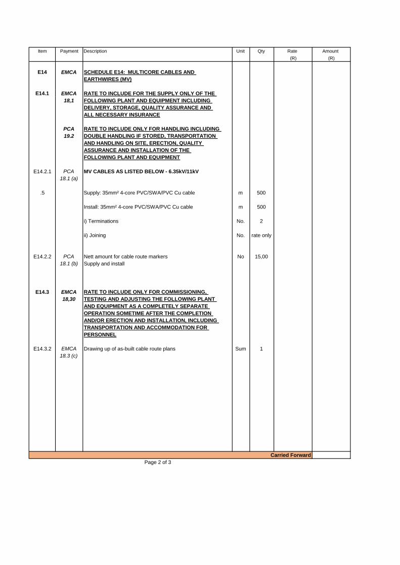
E14 EMCA SCHEDULE E14: MULTICORE CABLES AND
EARTHWIRES (MV)
E14.1 EMCA RATE TO INCLUDE FOR THE SUPPLY ONLY OF THE
18,1 FOLLOWING PLANT AND EQUIPMENT INCLUDING
DELIVERY, STORAGE, QUALITY ASSURANCE AND
ALL NECESSARY INSURANCE
PCA RATE TO INCLUDE ONLY FOR HANDLING INCLUDING
19.2 DOUBLE HANDLING IF STORED, TRANSPORTATION
AND HANDLING ON SITE, ERECTION, QUALITY
ASSURANCE AND INSTALLATION OF THE
FOLLOWING PLANT AND EQUIPMENT
E14.2.1 PCA MV CABLES AS LISTED BELOW - 6.35kV/11kV
18.1 (a)
R 0,00
.5 Supply: 35mm² 4-core PVC/SWA/PVC Cu cable m 500 0,00
0,00
Install: 35mm² 4-core PVC/SWA/PVC Cu cable m 500 0,00
0,00
i) Terminations No. 2 0,00
0,00
ii) Joining No. rate only 0,00
0,00
0,00
E14.2.2 PCA Nett amount for cable route markers No 15,00
18.1 (b) Supply and install
E14.3 EMCA RATE TO INCLUDE ONLY FOR COMMISSIONING,
18,30 TESTING AND ADJUSTING THE FOLLOWING PLANT
AND EQUIPMENT AS A COMPLETELY SEPARATE
OPERATION SOMETIME AFTER THE COMPLETION
AND/OR ERECTION AND INSTALLATION, INCLUDING
TRANSPORTATION AND ACCOMMODATION FOR
PERSONNEL
E14.3.2 EMCA Drawing up of as-built cable route plans Sum 1
18.3 (c)
0,00
Page 2 of 3
Carried Forward

Item Payment Description Unit Qty Rate Amount
(R) (R)
0,00
0,00
E13 EMCA SCHEDULE NO. E13:
MULTICORE CABLES AND EARTHWIRES (LV)
E13.1 EMCA RATE TO INCLUDE FOR THE SUPPLY ONLY OF THE
18,1 FOLLOWING PLANT AND EQUIPMENT INCLUDING
DELIVERY, STORAGE, QUALITY ASSURANCE AND
ALL NECESSARY INSURANCE
E13.2 PCA RATE TO INCLUDE ONLY FOR HANDLING INCLUDING
19.2 DOUBLE HANDLING IF STORED, TRANSPORTATION
AND HANDLING ON SITE, ERECTION, QUALITY
ASSURANCE AND INSTALLATION OF THE
FOLLOWING PLANT AND EQUIPMENT
E13.2.1 PCA 4 CORE CABLES AS LISTED BELOW
18.1 (a)
13.2.1.25 Supply: 25mm² x 4c PVC SWA PVC +ECC m 10
13.2.1.26 Install: 25mm² x 4c PVC SWA PVC +ECC m 10
13.2.1.27 i) Terminations No, 2
13.2.1.28 ii) Joining No, 0
.7 Install warning tape 300mm above all Ducts
i) Supply m 10
ii) Install m 10
0,00
0,00
0,00
0,00
0,00
0,00
0,00
SCHEDULE E14: MULTICORE CABLES AND
EARTHWIRES (MV)
0,00
Page 3 of 3
Total carried forward to summary of schedules
Brought Forward

Thornhill pump station
Summary of Schedules
Electrical & Electronic Scope of Works
Summary of Schedules
Schedule No. Description Price
E4 POWER TRANSFORMERS
E13 MULTICORE CABLES AND EARTHWIRES (LV)
E14 MULTICORE CABLES AND EARTHWIRES (MV)
Value Added Tax at 15%
Total Amount of Tender
Thornhill: Sewer pump station
Sub-Total A

Contract 154/2019 Part C3: Scope of Work Section C3.4: Specifications for Electrical and Electronic Works
Contractor Witness 1 Witness 2 Employer Witness 1 Witness 2
C:\Users\arthbl\AppData\Local\Microsoft\Windows\INetCache\Content.Outlook\PA6INFUI\20 Part C3.4.3.1 Variation and Additions Electrical and Electronic.docx June 2019
C3.4.3.1-11
1) Installation and Commission of one new outdoor 50kVA Diesel Generator unit (plinth
mounted) with AMF&ATS including all operation and maintenance manuals (3 sets), technical
data sheets, spares lists etc. The generator will be installed in a designated area at the sewer
pump station, refer to the applicable drawings.
2) Installation and Commissioning of ONE off new fully Automatic Mains Failure &
Automatic Transfer Switch (AMF&ATS) electrical panel (part of the main MCC) and associated
equipment.
3) Provide monthly testing and routine maintenance (Service Level Agreement (SLA)) on the
system for the duration of the Guarantee period (12 months)
The standby diesel generator installations should comply with ESGS particular specification,
schedule of quantities and drawings.
PS-EMCC-1-2 EMERGENCY GENERATOR CHANGE OVER-SYSTEM
The standby generator change-over system should provide normal as well as a standby power to the sewer pump
station’s main distribution board.
The standby generator change-over panel will be fed from a 50kVA transformer, refer to the PS-EPPT project
specifications.
PS-EPPT POWER TRANSFORMERS (SEWER PUMP STATION)
PS-EPPT-1 SCOPE OF WORKS
In order to power the water tower and temporary sewer pump station, the following power transformers are
supplied by the main Contractor and are NOT included in this tender;
1. 50kVA, 11kV/400V Outdoor, plinth mount transformer supplied by Main Contractor only.
The transformer for the sewer pump station should be fenced-off to avoid unauthorized access.
PS-EPPT-2 CONDITIONS OF SERVICE
All transformers shall be suitable for outdoor installation and shall be equipped with low and medium voltage
weatherproof cable end boxes and have adequate cooling without forced ventilation.
Contract 154/2019 Part C3: Scope of Work Section C3.4: Specifications for Electrical and Electronic Works
Contractor Witness 1 Witness 2 Employer Witness 1 Witness 2
C:\Users\arthbl\AppData\Local\Microsoft\Windows\INetCache\Content.Outlook\PA6INFUI\20 Part C3.4.3.1 Variation and Additions Electrical and Electronic.docx June 2019
C3.4.3.1-12
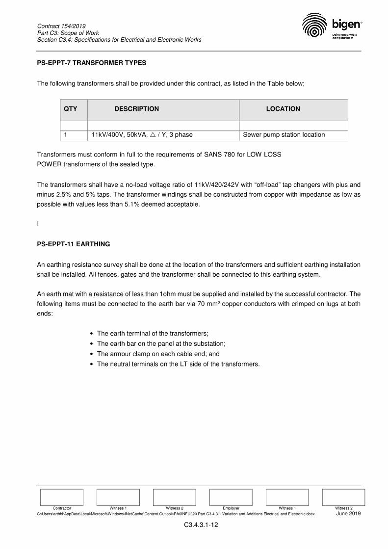
PS-EPPT-7 TRANSFORMER TYPES
The following transformers shall be provided under this contract, as listed in the Table below;
QTY DESCRIPTION LOCATION
1 11kV/400V, 50kVA, / Y, 3 phase Sewer pump station location
Transformers must conform in full to the requirements of SANS 780 for LOW LOSS
POWER transformers of the sealed type.
The transformers shall have a no-load voltage ratio of 11kV/420/242V with “off-load” tap changers with plus and
minus 2.5% and 5% taps. The transformer windings shall be constructed from copper with impedance as low as
possible with values less than 5.1% deemed acceptable.
I
PS-EPPT-11 EARTHING
An earthing resistance survey shall be done at the location of the transformers and sufficient earthing installation
shall be installed. All fences, gates and the transformer shall be connected to this earthing system.
An earth mat with a resistance of less than 1ohm must be supplied and installed by the successful contractor. The
following items must be connected to the earth bar via 70 mm² copper conductors with crimped on lugs at both
ends:
• The earth terminal of the transformers;
• The earth bar on the panel at the substation;
• The armour clamp on each cable end; and
• The neutral terminals on the LT side of the transformers.

Particular Specifications
EPCC - Motor Control Centers
i April 2019
PARTICULAR SPECIFICATIONS:
EMCC – ELECTRICAL/ELECTRONIC: MOTOR CONTROL CENTERS
PRELUDE
This particular specification details the successful supply, manufacturing, factory inspection test at the
contractors premises, careful handling / transportation to the clients premises, safe storage as required and
successful installation and commissioning for the above mentioned.
The contractor will furthermore responsible to uphold the electrical equipment during the Defects Liability
Period.
This particular specification should be read in conjunction with the following;
Section C3.4.3 of the tender document – Variation and additions to the Electrical / Electronic
standard and particular specifications; and
Associated drawings as issued with the Tender document; and
Schedule of Quantities as per project specific.
Whereas conflicts in the above mentioned exits, this should be brought under the attention of the Engineer
within a week before the Tender closes.
All materials and equipment to be supplied shall be new and of the best quality available.
All equipment shall bear the SABS mark.

Particular Specifications
EPCC - Motor Control Centers
ii April 2019
EPPT: POWER TRANSFORMERS
INDEX
Item Description Page No.
PPT 1 PPT POWER TRANSFORMERS ..................................................................................................... 1
PPT 2 SCOPE ............................................................................................................................................. 1
PPT 3 CONDITIONS TO SERVICE ............................................................................................................ 1
PPT 4 STANDARDS AND TESTS .............................................................................................................. 1
PPT 5 STANDARDS AND DRAWINGS ...................................................................................................... 2
PPT 6 INDOOR TYPE ................................................................................................................................. 2
PPT 7 OUTDOOR TYPE ............................................................................................................................. 3
PPT 8 INFORMATION TO BE SUBMITTED WITH TENDERS .................................................................. 3
PPT 9 INSTALLATION OF POWER TRANSFORMERS ............................................................................ 4
PPT 10 TESTING AND COMMISSIONING OF POWER TRANSFORMERS .............................................. 4
PPT 11 EARTHING ....................................................................................................................................... 5
PPT 12 MEASUREMENT AND PAYMENT ................................................................................................... 5
Particular Specifications
EPCC - Motor Control Centers
PPT-1 April 2019
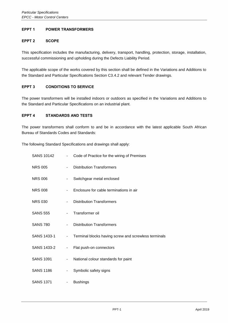
EPPT 1 POWER TRANSFORMERS
EPPT 2 SCOPE
This specification includes the manufacturing, delivery, transport, handling, protection, storage, installation,
successful commissioning and upholding during the Defects Liability Period.
The applicable scope of the works covered by this section shall be defined in the Variations and Additions to
the Standard and Particular Specifications Section C3.4.2 and relevant Tender drawings.
EPPT 3 CONDITIONS TO SERVICE
The power transformers will be installed indoors or outdoors as specified in the Variations and Additions to
the Standard and Particular Specifications on an industrial plant.
EPPT 4 STANDARDS AND TESTS
The power transformers shall conform to and be in accordance with the latest applicable South African
Bureau of Standards Codes and Standards:
The following Standard Specifications and drawings shall apply:
SANS 10142 - Code of Practice for the wiring of Premises
NRS 005 - Distribution Transformers
NRS 006 - Switchgear metal enclosed
NRS 008 - Enclosure for cable terminations in air
NRS 030 - Distribution Transformers
SANS 555 - Transformer oil
SANS 780 - Distribution Transformers
SANS 1433-1 - Terminal blocks having screw and screwless terminals
SANS 1433-2 - Flat push-on connectors
SANS 1091 - National colour standards for paint
SANS 1186 - Symbolic safety signs
SANS 1371 - Bushings

Particular Specifications
EPCC - Motor Control Centers
PPT-2 April 2019
EPPT 5 STANDARDS AND DRAWINGS
All materials used shall satisfy the relevant SANS specification and may only deviate from it upon a definite
instruction in this specification. The successful Tenderer shall ensure that he possesses the latest edition of
the relevant SANS specifications as listed in this specification.
EPPT 6 INDOOR TYPE
The transformers shall be of the free breathing indoor, category 1, DYN 11, low loss type with copper
windings and bushings suitable for indoor use, all in accordance with SANS 780. Transformers shall be
supplied with all the necessary oil. Transformer oil shall comply with SANS 555. The transformer no load
voltage shall be specified in the Variations and Additions to the Standard and Particular Specifications. A
five position tap changer shall be supplied to ensure the designed secondary voltage at plus/minus 5 % of
the primary voltage in steps of 2,5%.
The transformers shall be matched for parallel operation with percentage voltage impedance tolerance
between parallel operated transformers not exceeding 2,5% of rated voltage impedances, same inherent
phase angle difference between primary and secondary terminals, same voltage ratio, same polarity and
same phase sequence.
Apart from the compulsory accessories listed in table 1 of SANS 780. The transformer shall be equipped
with an Oil-level gauge, oil drain plug, bolted tank cover, two shafts and four rollers. A dial type
instantaneous and maximum registering indicating thermometer, Bucholz relay (if specified in the Variations
and Additions to the Standard and Particular Specifications), trip and alarm contacts on the thermometers
and Bucholz relay. The alarm and trip contacts shall be wired to a separate transformer side mounted
termination box equipped with rail mounted termination blocks and 3CR12 unpainted removable cable gland
plate.
The transformer shall be supplied with a cable end box for termination of medium voltage cables by means
of heat shrinkable terminations complete with wooden cable clamps and secondary cables by means of
cable glands. Cable terminations shall be suitable to accommodate the cable or cables for each circuit as
specified. This applies not only to the number of cores, size and conductor material, but also to the type and
construction of the cables. Gland plates in the secondary cable end boxes shall be manufactured from
unpainted 3CR12 steel with thickness to suit the cable sizes.
Cable end boxes and terminations shall be complete with the necessary clamps, glands, extension busbars if
necessary and other accessories.
Before ordering the Contractor shall ensure that substation doors and transformer platforms are suitably
sized for the transformers.
Before commissioning the transformer, the contractor shall ensure that the transformer is properly filled with
oil. All the connection terminals shall be taped with insulation tape corresponding with the respective phase
colours.

Particular Specifications
EPCC - Motor Control Centers
PPT-3 April 2019
EPPT 7 OUTDOOR TYPE
The outdoor type transformers to be supplied and installed under this Contract shall have a normal no-load
voltage ratio as specified with “off-load” tap changer with ±2,5% and 5% taps. The transformer no load
voltage shall be specified in the Variations and Additions to the Standard and Particular Specifications.
The transformers shall be matched for parallel operation with percentage voltage impedance tolerance
between parallel operated transformers not exceeding 2,5% of rated voltage impedances, same inherent
phase angle difference between primary and secondary terminals, same voltage ratio, same polarity and
same phase sequence. Gland plates in the secondary cable end boxes shall be manufactured from
unpainted 3CR12 steel with thickness to suit the cable sizes
The transformer shall comply with the requirements of SANS 780 as amended to date for low loss
transformers with copper windings and bushings suitable for indoor use and shall be of the free breathing
outdoor type (or as specified in the Variations and Additions to the Standard and Particular Specifications)
fitted with weatherproof MV and LV cable end boxes for termination of medium voltage cables by means of
heat shrinkable terminations complete with wooden clamps and secondary cables by means of cable glands
secured to a 3CR12 unpainted gland plate.
The transformer shall be supplied completely filled with oil to SANS 555.
In addition to the standard fittings to be provided in accordance with Table I of SANS Specification No. 780,
the transformer shall be provided with a detail type instantaneous indicating and maximum registering
thermometer, Bucholz Relays (if required), Trip and alarm contacts on the thermometers and Bucholz relay.
The alarm and trip contacts shall be wired to a separate transformer side mounted weatherproof termination
box equipped with rail mounted termination blocks and removable 3CR12 unpainted cable gland plate.
The transformer shall be provided complete with two axles and four rollers to facilitate rolling of the
transformer in the longitudinal direction,
Before ordering the Contractor shall ensure that transformer platforms are suitably sized for the transformers.
Before commissioning the transformer, the contractor shall ensure that the transformer is properly filled with
oil. All the connection terminals shall be taped with insulation tape corresponding with the respective phase
colours.
EPPT 8 INFORMATION TO BE SUBMITTED WITH TENDERS
Three copies of each of the following drawings shall accompany each tender in respect of the transformers
offered:
Outline drawings of the transformer complete with all its accessories, showing main overall dimensions; and
Drawings of the HT and LT bushings.

Particular Specifications
EPCC - Motor Control Centers
PPT-4 April 2019
EPPT 9 INSTALLATION OF POWER TRANSFORMERS
The power transformers shall be installed in the indoor switch room in the positions indicated on the
drawings in such a way that the LT bushings of the two adjacent transformers are facing each other.
Outdoor transformers shall be installed in a similar manner and as indicated on the drawings and can be
either plinth or pole mounted.
The high-tension terminals on each transformer must be connected to the corresponding medium voltage
circuit breaker by means of medium voltage cable via the cable ducts in the floor. At the transformer the
cable must be terminated by means of the specified cable end boxes.
The neutral terminal on the LV side of each transformer as well as its earth terminal shall be connected to
the substation earth as specified elsewhere in this document.
The connections between the low voltage terminals and the relevant board shall be done by means of the
specified cable. The cable shall be terminated at the transformer by means of a heat shrinkable dry type
crimped end kit.
After testing, the terminals must be insulated with busbar putty and taped with coloured PVC tape.
The necessary concrete plinths for the transformers will be provided by others under this contract.
On completion of the installation, but prior to commissioning the contractor shall do the following:
( a ) Ensure that all stoppers have been removed from the breather pipe and oil conservator
connection pipes on each transformer;
( b ) Check the oil level of each transformer and top up if necessary;
( c ) Check the tap positions on the transformer tap changers and ensure that both are in the
same positions;
( d ) Check the elements of the dehydrating breathers on the transformers in order to ensure
that these are dry. Replace if necessary; and
( e ) Check each transformer and dehydrating breather assembly for oil leaks and rectify if
necessary.
( f ) Remove all packings from relays and instruments.
EPPT 10 TESTING AND COMMISSIONING OF POWER TRANSFORMERS
On commissioning of the power transformers, the following shall be done;
( a ) The contractor shall verify phase denomination on both HV and LV sides prior to
terminating the cables.
( b ) After energising the contractor shall proof phase rotation on the LV side of all transformers.
( c ) After all testing had been carried out satisfactorily the transformer terminals and the
terminals on the end boxes must be insulated with busbar putty and taped with coloured
PVC tape. All arcing horns (if any) must be removed.
( d ) All transformers shall be properly and permanently labeled in accordance with the feeder
switchgear labeling system.

Particular Specifications
EPCC - Motor Control Centers
PPT-5 April 2019
EPPT 11 EARTHING
All transformers shall be earthed to the common medium voltage earthing system by means of 70mm² bare
copper conductors.
The contractor shall do all the bonding and earthing in accordance with the latest addition of the "Code of
Practice for the Wiring of Premises" SABS 0142.
Design and Approval
The Contractor shall allow for soil resistivity tests to be performed on site. A detailed report on the resistivity
tests shall be submitted to the Engineer together with a preliminary earthing scheme showing how the
Contractor envisages installing the earth mat before commencing installation of the earth mat. The
Contractor shall employ a specialist to investigate, plan and install the earthing installation.
The earth mat installation shall incorporate earthing electrodes at the extreme corners of the station, in the
vicinity of earthing switches and transformer neutrals. The substation fences shall also be earthed at regular
intervals including all substation gates. The installed maximum earth resistance shall be 1 Ω, or as agreed by
the Engineer. The earth conductors shall generally be laid at a depth of more than 500 mm below the
finished surface.
The complete earth mat design shall be submitted for written approval. The Engineer may then add or delete
equipment and change the design of the earth system if he so requires. The installation of the earth mat shall
be so arranged as not to cause delays in civil works.
Earth Resistance Survey
If specified in the Variations and Additions to the Standard and Particular Specifications. The Contractor will
be responsible to have an earth resistance survey carried out on site by a specialist in this field, to be
approved by the Engineer. The test shall be done on the undisturbed site, i.e. before earth works, trenching,
building etc. commence.
The Engineer shall attend the survey. The Contractor shall inform the Engineer in good time when the test is
scheduled to take place. If it is done without his or his representative being present, the test shall be
repeated in the Engineer’s presence at no additional cost.
The results of this survey will be used to adjust the earthing system as specified herein, if necessary, on the
basis of the quoted rates.
Payment for the services of the specialist shall be by the Contractor.
EPPT 12 MEASUREMENT AND PAYMENT
Measurement and payment will be done in accordance with the methods stated below:

Particular Specifications
EPCC - Motor Control Centers
PPT-6 April 2019
Supply and Delivery to Site (Excluded from this tender)
Pay Item Unit
( a ) Supply and delivery to site of power transformers (Excluded from this tender)
( b ) Supply and delivery to site of substation earthing system (Excluded from this tender)
Installation
Pay Item Unit
( a ) Site installation of power transformers Each
( b ) Installation of substation earthing system Sum
Commissioning
Pay Item Unit
( a ) Commissioning of power transformers Each
( b ) Commissioning of substation earthing system Sum