Embed Size (px)
Citation preview

www.theihe.org | 1
Passive Safety Electrical GuideElectrical requirements for passively safe ITS roadside installations to BS EN 12767
theihe.org
September 2021

2 | www.theihe.org
Institute of Highways EngineersFloor 4Euston House24 Eversholt StreetLondonNW1 [email protected]
First published September 2021© 2021 Institute of Highways Engineers
In cooperation with:Mott MacDonald4th FloorMountbatten HouseGrosvenor SquareSouthamptonS015 2JU
T +44 (0)23 8062 8800F +44 (0)23 8064 7251mottmac.com
DisclaimerThe Institute of Highways Engineers and the other contributors to this Guide have endeavoured to ensure the accuracy of its contents. However, the guidance and recommendations given should be reviewed in the light of the circumstances of each particular installation and specialist advice sought as necessary. This guide is supplied on the condition that no liability for negligence or otherwise can be accepted by the Institute, its servants and agents, nor by other contributors.For future editions, the IHE would appreciate being informed of any error identified or of any situation where following the guidance given herein has led to a problem in practice.
About the authorAlistair Gollop, FIHE, MIET is the Global Transport Technology Technical Champion at Mott MacDonald. As a recognised Intelligent Transport Systems (ITS) industry figure with 30 years in-depth experience, he has a detailed knowledge of specialist technologies and equipment, standards and statutory requirements, along with ancillary issues, such as passive safety and the implications these pose on the design and management of traffic system installations.
IHE Passive Safety Electrical Guide 2021This document provides guidance about the implications posed for the electrical designs of roadside Intelligent Transport Systems (ITS) deployments, by the use of passively safe structures used to mount equipment on.

www.theihe.org | 3
Contents
1. Introduction 4
2. How does the 2019 edition of BS EN 12767 effect electrical installations? 5
3. What happens when roadside structures with electrical installations are struck? 6
4. Example of a pole strike incident 7
5. What are the available design solutions to achieve Impact Electrical Isolation (IEI)? 8
6. Suggested best practice 9
7. Risk Assessment 10
8. Extra Low Voltage Installations 14
9. Supporting Issues 15

4 | www.theihe.org
1. Introduction
This Guidance Note has been produced to assist highway and road authorities, consultants and contractors who design and implement roadside Intelligent Transport Systems (ITS) equipment deployments, such as Traffic Signals. This document is advisory, to provide guidance regarding the implications that are posed by the electrical safety requirements for the majority of passively safe ITS roadside installations. It should be read in conjunction with BS EN 12767:2019 “Passive safety of support structures for road equipment”.
The necessity for this guidance document has been heightened due to changes in the 2019 version of the BS EN 12767 standard, which includes the removal of electrical requirements from the National Annex. Due to the complexity of cable arrangements found in typical ITS installations such as traffic signals, this omission poses potential problems to practitioners undertaking the design, specification or management of ITS equipment. It is not unusual to have a mix of cable types with multiple cores for numerous electrical circuits, mixed in with data/communications, coax video/antenna feeds and separate power supply cables for ancillary units within roadside equipment.
This document therefore examines why Impact Electrical Isolation (IEI) systems should be considered when designing any roadside ITS installation, including those mounted on passively safe or traditional structures. It looks at why an IEI system may be required in addition to standard electrical protective devices, the different types of IEI solutions which are commercially available in the UK, and how the selection of the type of pole and column should influence the IEI technology used.
It should be noted that for street lighting columns and illuminated signs, reference should be made of the separate guidance produced by The Institution of Lighting Professionals (ILP).
An example of a shared lighting column with separate door apertures for electrical terminations of street lighting and traffic signals

www.theihe.org | 5
2. How does the 2019 edition of BS EN 12767 effect electrical installations?
BS EN 12767 is the standard for “Passive safety of support structures for road equipment”, specifying the requirements, classification and test methods for poles and columns, that are ‘forgiving’ in the event of being struck by an errant vehicle. These are used to mount signs and equipment adjacent to the highway. Previous versions of BS EN 12767 included electrical recommendations in the National Annex for the UK.
The electrical items were primarily included because of concerns that the presence of cables within structures could adversely affect the failure mode of the crash friendly structure in the event of a vehicle strike, resulting in the tethering of poles and columns. Because of this, the advice concentrated on the use of ‘snatch plugs’ which physically separate when the pole is struck. The electrical isolation provided by these was seen as a secondary benefit. The annex also stated that electrical circuit protective devices could be used to provide electrical isolation. The standard was written before commercially available impact or tilt switch systems became available, and therefore did not explicitly consider their use. The current advice in the National Annex has been updated to state “In the UK, cable installations to passively safe supports must therefore still comply with all appropriate electrical regulations, standards and guidance without tethering those structures intended to shear or slip”, but does not explicitly cover Impact Electrical Isolation (IEI) to provide protection in the event of a vehicle striking a roadside structure.
Excerpt of the National Annex from the previous version of BS EN 12767:2007 covering electrical requirements which are no longer covered in the 2019 version of the standard.

6 | www.theihe.org
3. What happens when roadside structures with electrical installations are struck?
Irrespective of the type of structure, when poles are struck by an errant vehicle, items of electrical installations, such as luminaires, signal heads, CCTV cameras etc are often shed from the pole on impact, due to their mass. This is particularly prevalent with structures that do not breakaway (non-separating), particularly traditional steel non-passive structures.
In the left example of a passively safe traffic signal pole which was struck by a car, the signal head detached from the pole ending up on the ground, in the location indicated immediately adjacent to the pole. This resulted in the electrical cable to the head dangling down the side of the pole with exposed ends to the cable cores.
Whether the structure is designed to breakaway (separating) on impact or not, it can be seen that the integrity of electrical installations in roadside structures are typically compromised, leaving potentially live conductors exposed.
Cables are also commonly damaged near to ground level in all types of posts, irrespective of if they are designed to be separating or non-separating on impact, and damage can also occur in traditional steel products, which often fail in potentially devasting effect when struck. The quality of an installation design will not preclude the incidence of vehicle strikes occurring, accidents occur across the entire highway network. Whatever the causal factor, it affects drivers of all backgrounds, on roads of all types, and importantly to note, not just high-speed roads. In addition to the drivers of errant vehicles, passengers, passers-by and members of the emergency services can also be impacted by these events.
An example of a passively safe ramp metering installation
The traffic signal head (location indicated) next to the passively safe pole which was struck by an errant vehicle

www.theihe.org | 7
4. Example of a pole strike incident
In this example of a passive aluminium traffic signal pole which was struck by a car at comparatively low-speed, you can see that it folded flat from the top of the retention socket it was installed in. The Steel Wire Armoured (SWA) cable in the pole was crimped so tightly in the folded section, that it could not be extracted without cutting it free. It is thought therefore, that if a snatch plug installation had been used to provide IEI at this traffic signal it is doubtful that the plug would have been able to separate to achieve successful protection.
A passively safe pole that has been struck by an errant vehicle, after being extracted from its retention socket foundation
The control module indicator illuminated to indicate an impact event
The associated circuit breakers had been successfully tripped
This pole was equipped with an impact sensor to provide the IEI protection, and this successfully triggered on impact, isolating the electrical circuits to this structure. This illustrates the importance of selecting the appropriate IEI technology for the failure mode of each individual roadside structure to be protected and recognising that one solution may not be appropriate for all situations.
8 | www.theihe.org
5. What are the available design solutions to achieve Impact Electrical Isolation (IEI)?
From experience of numerous crash tests/demonstrations and real-life examples, the perceived issue of tethering of poles and columns by the presence of cables within these, has not been seen to have an adverse impact on their performance. This is because, even though Steel Wire Armoured (SWA) cables are commonly used, the cables tend to readily detach at the termination points within the structure because of the forces exerted on them. Therefore, the current thoughts for best practice are:
Snatch Plugs – for use on Separating (SE) columns – These are commonly supplied as moulded cable assemblies and can be highly successful when correctly installed at ground level within the column. However, these will not work effectively if they are incorrectly located, such as in an adjacent access chamber or too high up within a pole. The cable assemblies also need to be tightly tethered within the duct network and in the pole, to guarantee separation at the earliest point of an incident. Because of the required location, they can be difficult to install, difficult to undertake periodic inspections of and they may introduce an additional point of failure.
Impact / Tilt Sensors – for use on Non-separating (NS) and Separating (SE) columns – These systems provide effective Impact Electrical Isolation (IEI) in the event of a vehicle strike, but can be costly if a large number of isolators are required to protect multiple cores. They work by installing a sensor on the column, which when struck or if disconnected, cause circuit breakers located in an adjacent cabinet or chamber enclosure, to operate, providing full IEI of the installation.
Circuit Protective Devices – most applicable to traditional non-passive columns – In accordance with BS 7671 “Requirements for Electrical Installations”, Circuit Protective Devices will be required to provide electrical protection for circuits for all installations, however, they cannot guarantee Impact Electrical Isolation is achieved in the event of a vehicle striking a pole on their own. This is because these types of devices are designed to provide protection from electrical malfunctions (such as a short circuit) to operate the device. The requirement for achieving electrical isolation after a vehicle strikes a structure is within 0.4 seconds, but as these devices are not specifically IEI solutions (and with degrading installations or poorly specified circuits), compliance with this requirement cannot be guaranteed.
It is important to ensure that the IEI used for supports is appropriate for the way in which individual poles or columns operate when struck, and because of this, the decision for the type of IEI used should only be made after the support type has been chosen. The pole selection is therefore the critical element that then dictates the requirements for ancillary equipment, such as the type of IEI used. A risk assessment-based process should be used to document the decision making to select, not only the IEI technology to be incorporated within the infrastructure, but also the other elements for the installation, including electrical, civils and ITS equipment.

www.theihe.org | 9
As with any other type of electrical equipment, IEI devices may suffer from failure during the lifetime of an installation. Because of this, the designer should consider the effect that a failure mode might have on the overall operation of the ITS installation and ensure that the proposed IEI is appropriate for the intended use. Impact Electrical Isolation (IEI) systems triggered by an impact / tilt sensor are available commercially with outputs which can not only provide information when an impact event results in the system being triggered, but also when system or power failures occur. To make best use of these, it is recommended that where available, the IEI outputs are routed to a remote monitoring system to allow fault conditions to be automatically reported to the appropriate control centre and equipment maintenance contractor.
6. Suggested best practice
For roadside ITS installations mounted on passively safe structures, it is recommended that for Non-Separating (NS) installations, the appropriate solution is an Impact Electrical Isolation (IEI) system which is triggered by either an impact or tilt sensor on each structure that incorporates an electrical installation. These may also be used as an appropriate solution for Separating (SE) installations, although there is scope in these structures to use Snatch plugs instead.
Pole type Recommended solutionNS (Non-separating) Passive Impact Electrical Isolation (IEI) system triggered by an
impact / tilt sensor on eachpole to be protected
SE (Separating) Passive Either:• Snatch plug installation• IEI system triggered by an impact / tilt sensor on each
pole to be protected
An impact sensor within a cable termination enclosure in a passive traffic signal pole
A pre-moulded Snatch Plug cable assembly
10 | www.theihe.org
It is not recommended to install both Impact Electrical Isolation (IEI) triggered by an impact / tilt sensor and Snatch Plug solutions on the same structure, but these may coexist and be installed separately across a site as appropriate for individual structures.
Although traditional non-passive poles and columns used for roadside ITS structures are not normally equipped with Impact Electrical Isolation (IEI) triggered by an impact / tilt sensor or Snatch Plug solutions to achieve electrical isolation in the event of being struck by a vehicle, it is recommended that a risk assessment based procedure is used to assess the requirements and to record the decisions made when using these.
7. Risk Assessment
It is recommended that as part of the duties for Clients, Designers and Contractors under The Construction (Design and Management) Regulations (CDM), a risk assessment based procedure to document the decision-making process for all equipment specified as part of an ITS installation is undertaken, irrespective of the type of structure or isolation system used. Along with safe designs and communicating any remaining significant risks, this guidance document fulfils the three fundamentals for the Principles of Prevention recognised as being essential for the achievement of successful Design Risk Management (DRM) in construction projects.
Designer Risk Assessments should consider a wide range of issues, and as with any meaningful assessment process, should use the ERIC principles to seek to Eliminate risks, and only when this is not achievable to Reduce risks or to Inform parties about any residual significant risks. This will allow any Control measures to be established prior to them being required. Consideration will need to be given to issues that will be faced during the whole life cycle of the facility, covering the construction/installation, use, maintenance and decommissioning phases. Each roadside ITS installation project will face very different issues because of the vast array of equipment types and the individual characteristics for each installation site.
Because of this, the following points should be considered, alongside any other issues posed by the unique combination of the type of equipment and its proposed location:
• ITS roadside structure – material
Roadside structures used for mounting ITS equipment, such as traffic signal poles, can pose a threat to vehicle occupants in the event of an errant vehicle striking a roadside structure during a Road Traffic Incident (RTI). The selection process for the structure material (i.e. steel, aluminium, composite) should consider the speed limit / 85th percentile of vehicles at the site and the type of environment, such as are Non-Motorised Users (NMUs) present, quantity/demographics of NMUs, is it a rural or urban site, proximity to buildings and other structures.
Pole types should consider: • Steel poles – possible utilisation – urban, or if other objects are immediately adjacent
such as street furniture and buildings which might negate the operation of passively safe products.
• Non-separating (NS) passively safe – possible utilisation – lower speeds, and with NMU presence.
• Separating (SE) passively safe – possible utilisation – higher speeds, rural, little or no NMU presence.
www.theihe.org | 11
• ITS roadside structure – cable termination
The way in which cables are terminated (connected) within a roadside structure should be selected to be compatible with the type of pole or column being used.
Issues to consider: • Try to minimise the requirement for maintenance engineers to work at height adjacent
to the carriageway, for non-passive installations, such as a steel traffic signal pole using steel wire armoured (SWA) cable, instead of using the traditional pole cap assembly could the cable termination use a low-level door aperture instead?
• For tall structures the cable termination should be in a low-level door aperture or in an adjacent feeder pillar, however dependent upon what the structure is made of and where it is located, it may need to be protected by a Vehicle Restraint System (VRS).
• For non-separating (NS) passively safe poles equipped with an IEI system triggered by an impact / tilt switch, an SWA cable could be terminated within a low-level door aperture.
• For separating (SE) passively safe poles equipped with a snatch plug cable assembly, a SWA cable should be terminated using a bottle joint located within a chamber adjacent to the pole, with the snatch plug cable assembly restrained in both the chamber and pole, with the snatch plug located at ground level within the pole, then terminated in a low-level door aperture.
• For separating (SE) passively safe poles equipped with an IEI system triggered by an impact / tilt switch, an SWA cable could be terminated within a low-level door aperture.
• Electrical potential – voltage
Consideration should be given to the electrical potential (voltage) of ITS equipment mounted on roadside structures. Traditionally equipment was mains powered, this is categorised (confusingly) as Low Power or LV. Many modern products are now designed to use Extra-Low Voltage (ELV) supplies, these are at a maximum of 50v. ELV circuits greatly reduce the possibility of users or maintenance engineers being electrocuted. CDM regulations make this a compelling reason alone.
Voltage considerations: • For new installations ELV should be considered as the default, unless the class of
equipment is not available using ELV. • Existing installations undergoing comprehensive equipment replacement or upgrade
should consider ELV as the default. • Partial equipment replacement, it may not be feasible to implement ELV due to constraints,
in which case LV may be the only option. • Also look at the environmental benefits of ELV use. Commonly the reduced electrical
consumption and corresponding CO2 footprint, may result in payback period after a few years of operation, with ongoing electricity and CO2 emission savings for the life-time of the equipment. There may also be functional improvements associated with modern ELV equipment, such as LED traffic signal light sources which do away with the need for regular bulk lamp changes.

12 | www.theihe.org
• ITS roadside structure – height
The required height of the structure needs to consider and document the anticipated access arrangements required for maintenance.
Issues to consider: • Wherever possible locate serviceable equipment at low-level so that it is maintainable
without the need to work at height. • Lower structures such as a 4m traffic signal pole, is there physically room to site an
A-frame to access equipment. • For higher structures, such as a 6m tall traffic signal pole, is it possible to utilise a Mobile
Elevated Work Platform (MEWP) without deploying traffic management. • For tall structures, such as a mast-arm, could a rotating design be used to overcome
road space issues, these benefit from a suitably located maintenance bay to allow MEWP access to be achieved off carriageway. Remember that they will require a periodic inspection regime.
• ITS roadside structure – mass
Would the size and weight of the roadside ITS equipment negate the benefits of using a passively safe support structure in the event of a vehicle strike? In these cases alternatives will need to be considered to locate the structure behind suitable Vehicle Restraint System (VRS) or in a position and at a sufficient distance away from the carriageway, so that it is highly unlikely to be struck by an errant vehicle.
• Ancillary street furniture
The existence of street furniture can be visually intrusive and pose a threat to vehicle occupants in the event of an RTI.
Issues to consider: • Pedestrian guardrailing is not forgiving, particularly if hit end on. Could this be replaced
with suitable kerbing and surfacing treatments such as dissuasion paving • Could traffic signals be co-located with signs or street lighting to reduce the number
of roadside poles. • The close proximity of other roadside structures, such as lighting columns, signs
or buildings may preclude the safe operation of passively safe products.
www.theihe.org | 13
• Equipment cabinets – location issues
Equipment cabinets and feeder pillars should be located to allow maintenance access but away from the carriageway and footways.
The location of cabinets needs to account for: • Causing the view from/to pedestrians being obscured resulting in a risk of pedestrians
entering the carriageway without warning to approaching drivers. • The footway becoming blocked during maintenance activities which might force
pedestrians to enter the carriageway or introduce trip hazards. • Located to minimise the likelihood of cabinets being struck by an errant vehicle or by
maintenance / service / vegetation clearance vehicles. Could these be placed behind VRS or not opposite approaching vehicles. Consider the resulting disruption that would occur if the equipment were to be destroyed in an RTI.
• Ensuring maintenance engineers are not too close to the carriageway to minimise the likelihood of being struck by vehicles.
• Located as close as possible to maintenance vehicle parking provision to reduce the risk of dropping equipment in carriageway, the possibility of equipment being stolen or maintenance engineers suffering due to carrying loads to/from vehicle.
• Maintenance parking bay provision
During maintenance activities, engineers’ vehicles could obstruct the carriageway or footway. Is it possible to provide an allocated area for these vehicles to overcome issues which could put pedestrians and other road users at risk. An alternative maybe an off-line access using local or service road locations at high-speed sites.
The process and results of the Designers Risk Assessment should be recorded and included within the design file for the project.
14 | www.theihe.org
8. Extra Low Voltage Installations
Over the years, many have queried the need to include Impact Electrical Isolation (IEI) features for passively safe technology installations which only include Extra Low Voltage (ELV) circuits. This is because ELV systems are at a safe level below 50v RMS, so that they do not present an electric shock hazard.
However, they could still pose a risk of causing sparks, which theoretically could ignite a fire in the event of a vehicle having a ruptured fuel line or tank after hitting a pole. In addition, because emergency services will not necessarily know if an installation is ELV or not, the lack of an IEI system in place might delay their response to an incident.
As ELV installations become more prevalent across highway deployments, emerging technologies, such as distributed traffic signal architectures, are starting to see the integration of impact sensors into equipment. This trend should be encouraged, but consideration of how these facilities are implemented will need to ensure that they are suitable for the failure mode of the passively safe structures they are used with.
The design process for a project using ELV installations should include a designers’ risk assessment to document the decision-making process for the omission or inclusion of IEI features in a scheme. If Impact Electrical Isolation features are included, it is important to ensure that they are
appropriate for the types of passively safe poles and columns used in an installation and that the selection process for this is also recorded.
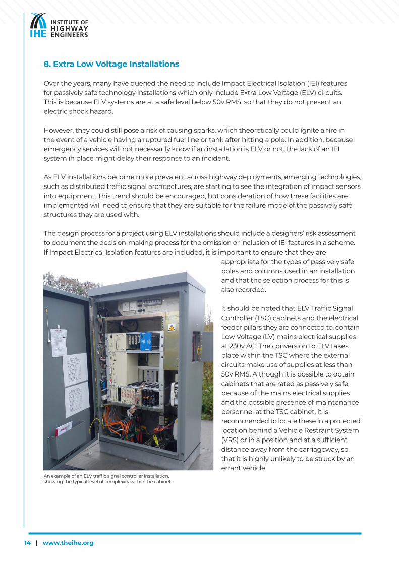
It should be noted that ELV Traffic Signal Controller (TSC) cabinets and the electrical feeder pillars they are connected to, contain Low Voltage (LV) mains electrical supplies at 230v AC. The conversion to ELV takes place within the TSC where the external circuits make use of supplies at less than 50v RMS. Although it is possible to obtain cabinets that are rated as passively safe, because of the mains electrical supplies and the possible presence of maintenance personnel at the TSC cabinet, it is recommended to locate these in a protected location behind a Vehicle Restraint System (VRS) or in a position and at a sufficient distance away from the carriageway, so that it is highly unlikely to be struck by an errant vehicle.
An example of an ELV traffic signal controller installation, showing the typical level of complexity within the cabinet
www.theihe.org | 15
9. Supporting Issues
When undertaking designs for passively safe technology installations, it is important to be aware of other issues which can have a positive impact on the safety of the installation, not only in the event of an accident, but also during maintenance activities.
In addition to diminishing the dangers associated with electric shock in the event of an incident, ELV installations offer other advantages that enhance safety. The design of most ELV equipment has driven the adoption of modern assemblies which are lighter than comparable equipment from just a few years ago. An example of this is traffic signal heads, because they no longer contain the heavy step-down transformers found in traditional style LV heads, they minimise the extent of secondary damage in the event of an accident. In future, this could also aid items to be designed to be more frangible in the event of an accident, breaking into harmless, smaller pieces, which would diminish the threat of injury to vehicle occupants and bystanders. ELV installations also make maintenance activities much safer, reducing the risk of electric shocks occurring whilst equipment is being worked on.
Many crash-friendly poles can also be supplied with low-level door apertures. These can be used to locate electrical terminations, which over-comes a lot of the installation and maintenance issues associated with working at height, which is particularly problematic when working in adverse weather conditions adjacent to moving traffic. Electrical terminations in pole apertures can also make use of cable termination enclosures, which offer protection to the live terminals, but can be visually inspected without requiring covers to be removed. They can also be used to house items such as impact sensors and can be removed from the pole during installation and maintenance activities. Many installations continue to use SWA cables, so the use of poles with low-level terminations also reduces the affect these rigid cables have on the failure mode of the pole if struck. For Snatch Plug installations, the use of light-weight bottle joints allows the moulded cable assemblies to be easily jointed to SWA cables in an adjacent access chamber. Because the weight of bottle joints is negligible, there is little stress on their cable glands, overcoming issues of water ingress that were commonly found with older solutions. Because passively safe installations are designed to take account of a vehicle strike, thought should also be given to making the reinstatement process quicker and easier. To achieve this, instead of using traditional concrete foundations, the use of pole retention sockets (that do not require any excavation during the reinstatement process) will allow for a short turn-round. It could also be possible to have all the pole mounted equipment fitted to the replacement pole in the maintenance contractor’s depot, rather than doing this on site, which would reduce the amount of time personnel need to be working next to the carriageway.
A major contributor to improving safety is the reduction in roadside clutter. Consideration should be given to minimising the quantity of roadside structures by using them to mount multiple types of equipment wherever possible. An example of this includes sharing lighting columns to also mount traffic signals or traffic monitoring CCTV. When undertaking this type of deployment, it is essential to make a structural assessment for the weight and windage of the additional items being mounted on a column. Thought should also be given to how electrical supplies and cut-outs are arranged, to ensure multiple electrical phases are not present on individual columns and to clearly label and separate electrical isolators. In order to reduce the likelihood of electric shock or equipment damage, Low-voltage (LV) and Extra-Low Voltage (ELV) circuits should not be mixed within multi-core cables, individual ducts or poles and columns.

INSTITUTE OF HIGHWAY ENGINEERSFloor 4 Euston House
24 Eversholt Street London NW1 1DBTel 0203 874 3066
Email [email protected] Website www.theihe.org
in association with