Embed Size (px)
Citation preview
Contents lists available at ScienceDirect
Acta Astronautica
journal homepage: www.elsevier.com/locate/actaastro
Online attitude determination of a passively magnetically stabilizedspacecraft
R. Burtona,b,c,⁎, S. Rocka, J. Springmannd, J. Cutlerd
a Stanford University, 496 Lomita Mall, Stanford, CA 94305, United Statesb NASA Ames Research Center, Moffett Field, CA 94035, United Statesc Millennium Engineering and Integration Services, 2231 Crystal Dr, Arlington, VA 22202, United Statesd University of Michigan, 1320 Beal Ave, Ann Arbor, MI 48109, United States
A R T I C L E I N F O
Keywords:Attitude determinationNano satellitesPassive magnetic stabilizationKalman FilterMEKFOnline estimation
A B S T R A C T
An online attitude determination filter is developed for a nano satellite that has no onboard attitude sensors orgyros. Specifically, the attitude of NASA Ames Research Center's O/OREOS, a passively magnetically stabilized3U CubeSat, is determined using only an estimate of the solar vector obtained from solar panel currents. Thefilter is based upon the existing multiplicative extended Kalman filter (MEKF) but instead of relying on gyros todrive the motion model, the filter instead incorporates a model of the spacecraft's attitude dynamics in themotion model. An attitude determination accuracy of five degrees is demonstrated, a performance verified usingflight data from the University of Michigan's RAX-1. Although the filter was designed for the specific problem ofa satellite without gyros or attitude determination it could also be used to provide smoothing of noisy gyrosignals or to provide a backup in the event of gyro failures.
1. Introduction
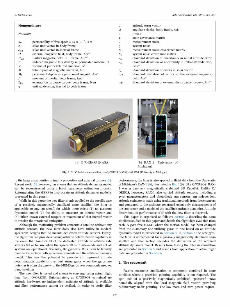
In this paper the problem of providing an online attitude determi-nation capability to satellites that have no dedicated attitude or attituderate sensing hardware is studied. The specific problem studiedoriginated from work relating to NASA Ames Research Center's O/OREOS [1] nano satellite, a 3U CubeSat illustrated in Fig. 1(a). Theprimary science mission on O/OREOS required neither an attitudepointing nor an attitude knowledge capability. To minimize missioncost, complexity and risk, a passive magnetic attitude stabilizationsystem was used and no attitude or attitude rate sensing hardware wasinstalled. After launch and completion of the primary science mission,however, there was a subsequent desire to estimate the attitude of thespacecraft to help with the design of a future mission. The only dataavailable to perform this task were the electrical currents from the bodymounted solar panels from which an estimate of the body frame sunvector, the unit vector pointing from the spacecraft to the sun, can bemade.
A single isolated measurement of a known inertial vector, such asthe sun vector, is insufficient to determine attitude due to a rotationalambiguity around the vector itself. Taking sequential measurements ofthe vector can help, although if the spacecraft is undergoing torque freemotion then the ambiguity will still remain. To resolve the ambiguity,the spacecraft's attitude motion either needs to be forced with a known
external torque that is aperiodic with the rotation in the body frame, orthe known inertial vector being measured needs to be moving in theinertial frame. For O/OREOS, the passive magnetic stabilizationsystem provides the external torques necessary to resolve the ambi-guity.
Attitude estimators that use sequential measurements incorporate amotion model whose purpose is to propagate the estimate betweeneach measurement. Existing attitude determination algorithms thatincorporate a motion model [2,3], have relied on gyro readings to drivethe motion model and so are not suitable for use in this case, where thespacecraft does not have gyros. The online attitude filter presented inthis paper instead uses a model of the spacecraft's attitude dynamics asthe motion model, allowing attitude determination to be performedusing only sequential sun vector measurements and no onboard gyros.
The new filter is based upon the popular multiplicative extendedKalman filter [4] (MEKF), a recursive estimator that in its originalformulation uses a gyro driven motion model. In an MEKF, spacecraftattitude is represented by the unit quaternion. In this work, the gyro-driven kinematic motion model in the original MEKF is replaced with amodel of the spacecraft attitude dynamics, a two step process requiringthe formulation of an attitude dynamics model and the reformulationof the original filter equations to account for the different motionmodel.
Formulating an accurate attitude dynamics model is non-trivial due
http://dx.doi.org/10.1016/j.actaastro.2017.01.024Received 8 October 2015; Accepted 19 January 2017
⁎ Corresponding author at: Stanford University, 496 Lomita Mall, Stanford, CA 94305, United States.
Acta Astronautica 133 (2017) 269–281
Available online 23 January 20170094-5765/ © 2017 IAA. Published by Elsevier Ltd. All rights reserved.
MARK
to the large uncertainties in inertia properties and external torques [3].Recent work [5], however, has shown that an attitude dynamics modelcan be reconstructed using a batch parameter estimation process.Reformulating the MEKF to incorporate an attitude dynamics model ispresented in this paper.
While in this paper the new filter is only applied to the specific caseof a passively magnetically stabilized nano satellite, the filter isapplicable to any spacecraft for which there exists (1) an accuratedynamics model (2) the ability to measure an inertial vector and(3) either known external torques or movement of that inertial vectorto resolve the rotational ambiguity.
Although the motivating problem concerns a satellite without anyattitude sensors, the new filter does also have utility in modernspacecraft designs that do include dedicated attitude sensors. Firstly,the algorithm can provide a backup attitude determination capability inthe event that some or all of the dedicated attitude or attitude ratesensors fail or for use when the spacecraft is in safe-mode and not allsystems are operational. Secondly, the gyro-free MEKF can be triviallymodified to include both gyro measurements and the attitude dynamicsmodel. This has the potential to provide an improved attitudedetermination capability over just using gyros when the gyros arenoisy, as is often the case with the MEMS gyros now commonly used onnano satellites.
The new filter is tested and shown to converge using actual flightdata from O/OREOS. Unfortunately, as O/OREOS contained noattitude hardware, no independent estimate of attitude is availableand filter performance cannot be verified. In order to verify filter
performance, the filter is also applied to flight data from the Universityof Michigan's RAX-1 [6], illustrated in Fig. 1(b). Like O/OREOS, RAX-1 was a passively magnetically stabilized 3U CubeSat. Unlike O/OREOS, however, RAX-1 also carried attitude sensors, including agyro, magnetometers and photodiode sun sensors. An independentattitude estimate is made using traditional methods from these sensorsand compared to the estimate generated using only measurements ofthe sun vector and a model of the satellite's attitude dynamics. Attitudedetermination performance of 5° with the new filter is observed.
This paper is organized as follows: Section 2 describes the nanosatellites studied in this paper and details the flight data available fromeach. A gyro free MEKF, where the motion model has been changedfrom the customary one utilizing gyros to one based on an attitudedynamics model is presented in Section 3. In Section 4 the new gyro-free filter is implemented for a passively magnetically stabilized nanosatellite and that section includes the derivation of the requiredattitude dynamics model. Results from testing the filter in simulationare presented in Section 5 and results from application to actual flightdata are presented in Section 6.
2. The spacecraft
Passive magnetic stabilization is commonly employed in nanosatellites where a precision pointing capability is not required. Thespin axis of a passively magnetically stabilized spacecraft staysnominally aligned with the local magnetic field vector, providingrudimentary nadir pointing. The low mass and zero power require-
Nomenclature
Notation
μ0 permeability of free space π= 4 × 10⁻⁷, H m−1
c solar unit vector in body framecECI solar unit vector in inertial frameH external magnetic field, body frame, Am−1
HECI Earth's magnetic field, ECI frame, Am−1
B induced magnetic flux density in permeable material, TV volume of permeable rod material, m3
M total dipole of magnetic material, Am2
MP permanent dipole in a permanent magnet, Am2
I moment of inertia, body frame, kgm2
Tdist external disturbance torque, body frame, N mq unit quaternion, inertial to body frame
a attitude error vectorω angular velocity, body frame, rads−1
t time, sΣ state covariance matrixν measurement noiseη system noiseΣν measurement noise covariance matrixΣη system noise covariance matrixσa0 Standard deviation of uncertainty in initial attitude errorσω0 Standard deviation of uncertainty in initial attitude rate,
rads−1
σc Standard deviation of errors in solar vectorσH Standard deviation of errors in the external magnetic
field, Am−1
σT Standard deviation of external disturbance torques, Am−1
Fig. 1. 3U CubeSat nano satellites, (a) O/OREOS (NASA), (b)RAX-1 (University of Michigan).
R. Burton et al. Acta Astronautica 133 (2017) 269–281
270
ments of the system make its use ideal in nano satellites. The twosatellites considered in this paper, NASA Ames Research Center's O/OREOS and the University of Michigan's RAX-1, are both passivelymagnetically stabilized 3U CubeSats. The passive magnetic stabiliza-tion system provides the external torques that are required to resolvethe rotational ambiguity around the single measurement vector andallow attitude determination to be performed.
2.1. Spacecraft background
The Organism/Organic Exposure to Orbital Stresses (O/OREOS)spacecraft, illustrated in Fig. 1(a), was a 3U CubeSat that carried twoastrobiology payloads to study the survivability and viability of thespace environment to live organisms and organics respectively. The O/OREOS spacecraft's passive attitude stabilization system consisted ofpermanent dipoles along the long axis, and hysteresis rods in the planeperpendicular to the long axis. While O/OREOS had no direct onboardattitude sensing, the spacecraft bus did monitor solar panel currents.
The first Radio Aurora Explorer satellite, RAX-1, another 3UCubeSat illustrated in Fig. 1(b), was developed to study magneticfield-aligned plasma irregularities in Earth's ionosphere. The satellitewas developed jointly by SRI International and the University ofMichigan. The science payload was an ultra high frequency (UHF)radar receiver. Working in conjunction with ground based incoherentscatter radar stations, the purpose of the mission was to improve theunderstanding of the ionospheric irregularities with the ultimate goalof enabling short-term forecasting. The passive magnetic attitudecontrol system consisted of four permanent magnets aligned with thelong z axis and two strips of HyMu80 soft magnetic material mountedin two axes perpendicular to the permanent magnets. RAX-1 included afull suite of attitude sensors consisting of multiple photodiodes, twothree-axis magnetometers, and a three-axis rate gyroscope [7]. Toimprove the accuracy of the magnetometer and photodiode measure-ments, an attitude-independent calibration was performed using anon-orbit magnetometer calibration algorithm developed to mitigate theeffect of nearby electronics on the magnetometers, which are em-bedded in the spacecraft [8].
2.2. Spacecraft data
Both satellites were secondary payloads on the same November2010 launch from Kodiak AK, and were inserted into a 650 km altitude,72° inclination low Earth orbit. After separation from the launcher,orbital position was determined by propagating two-line-element(TLE) ephemerides using the SGP4 [9] propagator. TLEs were updateddaily, leading to maximum orbit propagation errors of a few kilometers.
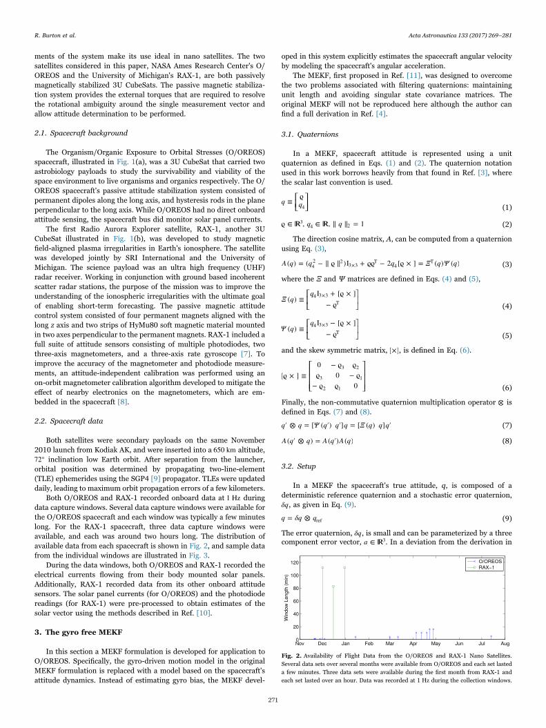
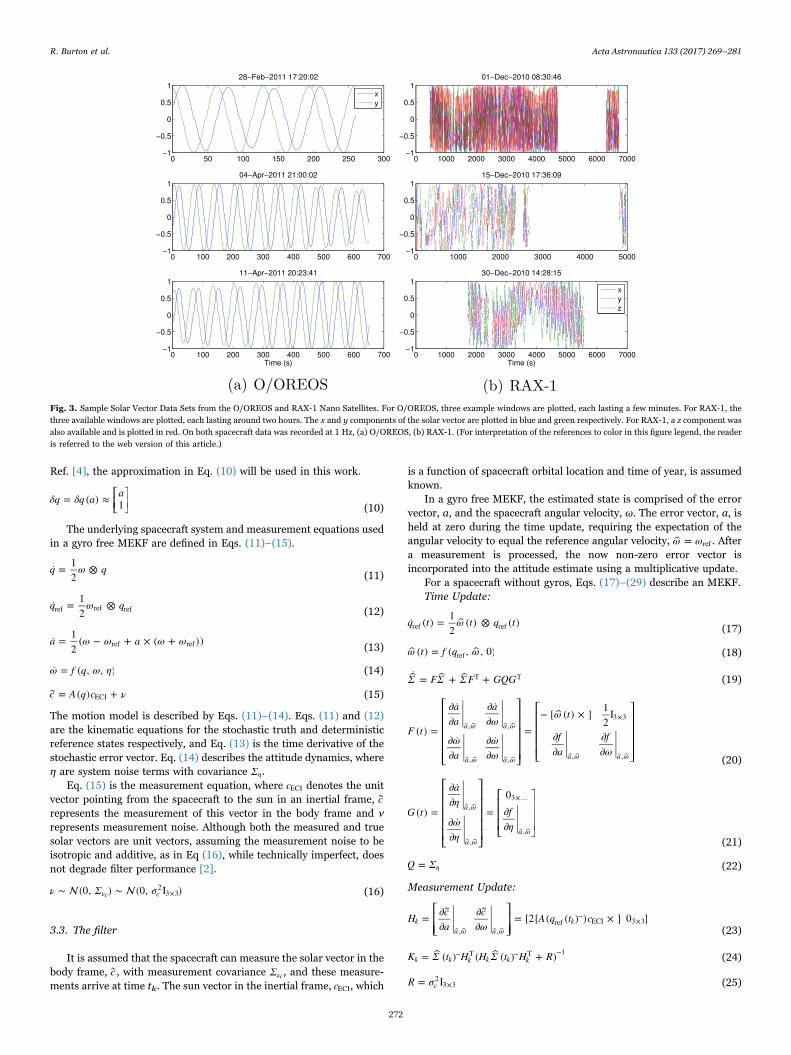
Both O/OREOS and RAX-1 recorded onboard data at 1 Hz duringdata capture windows. Several data capture windows were available forthe O/OREOS spacecraft and each window was typically a few minuteslong. For the RAX-1 spacecraft, three data capture windows wereavailable, and each was around two hours long. The distribution ofavailable data from each spacecraft is shown in Fig. 2, and sample datafrom the individual windows are illustrated in Fig. 3.
During the data windows, both O/OREOS and RAX-1 recorded theelectrical currents flowing from their body mounted solar panels.Additionally, RAX-1 recorded data from its other onboard attitudesensors. The solar panel currents (for O/OREOS) and the photodiodereadings (for RAX-1) were pre-processed to obtain estimates of thesolar vector using the methods described in Ref. [10].
3. The gyro free MEKF
In this section a MEKF formulation is developed for application toO/OREOS. Specifically, the gyro-driven motion model in the originalMEKF formulation is replaced with a model based on the spacecraft'sattitude dynamics. Instead of estimating gyro bias, the MEKF devel-
oped in this system explicitly estimates the spacecraft angular velocityby modeling the spacecraft's angular acceleration.
The MEKF, first proposed in Ref. [11], was designed to overcomethe two problems associated with filtering quaternions: maintainingunit length and avoiding singular state covariance matrices. Theoriginal MEKF will not be reproduced here although the author canfind a full derivation in Ref. [4].
3.1. Quaternions
In a MEKF, spacecraft attitude is represented using a unitquaternion as defined in Eqs. (1) and (2). The quaternion notationused in this work borrows heavily from that found in Ref. [3], wherethe scalar last convention is used.
⎡⎣⎢
⎤⎦⎥q q≡
ϱ4 (1)
q qϱ ∈ , ∈ , ∥ ∥ = 134 2 (2)
The direction cosine matrix, A, can be computed from a quaternionusing Eq. (3),
A q q q Ξ q Ψ q( ) = ( − ∥ ϱ ∥ )I + ϱϱ − 2 [ϱ × ] = ( ) ( )42 2
3×3T
4T (3)
where the Ξ and Ψ matrices are defined in Eqs. (4) and (5),
⎡⎣⎢
⎤⎦⎥Ξ q
q( ) ≡
I + [ϱ × ]− ϱ
4 3×3T
(4)
⎡⎣⎢
⎤⎦⎥Ψ q
q( ) ≡
I − [ϱ × ]− ϱ
4 3×3T
(5)
and the skew symmetric matrix, [×], is defined in Eq. (6).
⎡
⎣⎢⎢⎢
⎤
⎦⎥⎥⎥
[ϱ × ] ≡0 − ϱ ϱϱ 0 − ϱ
− ϱ ϱ 0
3 2
3 1
2 1 (6)
Finally, the non-commutative quaternion multiplication operator ⊗ isdefined in Eqs. (7) and (8).
q q Ψ q q q Ξ q q q′ ⊗ = [ ( ′) ′] = [ ( ) ] ′ (7)
A q q A q A q( ′ ⊗ ) = ( ′) ( ) (8)
3.2. Setup
In a MEKF the spacecraft's true attitude, q, is composed of adeterministic reference quaternion and a stochastic error quaternion,δq, as given in Eq. (9).
q δq q= ⊗ ref (9)
The error quaternion, δq, is small and can be parameterized by a threecomponent error vector, a ∈ 3. In a deviation from the derivation in
Fig. 2. Availability of Flight Data from the O/OREOS and RAX-1 Nano Satellites.Several data sets over several months were available from O/OREOS and each set lasteda few minutes. Three data sets were available during the first month from RAX-1 andeach set lasted over an hour. Data was recorded at 1 Hz during the collection windows.
R. Burton et al. Acta Astronautica 133 (2017) 269–281
271
Ref. [4], the approximation in Eq. (10) will be used in this work.
⎡⎣⎢
⎤⎦⎥δq δq a a= ( ) ≈ 1 (10)
The underlying spacecraft system and measurement equations usedin a gyro free MEKF are defined in Eqs. (11)–(15).
q ω q˙ = 12
⊗(11)
q ω q˙ = 12
⊗ref ref ref (12)
a ω ω a ω ω˙ = 12
( − + × ( + ))ref ref (13)
ω f q ω η˙ = ( , , ) (14)
c A q c ν= ( ) +∼ECI (15)
The motion model is described by Eqs. (11)–(14). Eqs. (11) and (12)are the kinematic equations for the stochastic truth and deterministicreference states respectively, and Eq. (13) is the time derivative of thestochastic error vector. Eq. (14) describes the attitude dynamics, whereη are system noise terms with covariance Ση.
Eq. (15) is the measurement equation, where cECI denotes the unitvector pointing from the spacecraft to the sun in an inertial frame, c∼
represents the measurement of this vector in the body frame and νrepresents measurement noise. Although both the measured and truesolar vectors are unit vectors, assuming the measurement noise to beisotropic and additive, as in Eq (16), while technically imperfect, doesnot degrade filter performance [2].
ν Σ σ∼ (0, ) ∼ (0, I )ν c2
3×3c (16)
3.3. The filter
It is assumed that the spacecraft can measure the solar vector in thebody frame, c∼, with measurement covariance Σνc, and these measure-ments arrive at time tk. The sun vector in the inertial frame, cECI, which
is a function of spacecraft orbital location and time of year, is assumedknown.
In a gyro free MEKF, the estimated state is comprised of the errorvector, a, and the spacecraft angular velocity, ω. The error vector, a, isheld at zero during the time update, requiring the expectation of theangular velocity to equal the reference angular velocity, ω ω= ref . Aftera measurement is processed, the now non-zero error vector isincorporated into the attitude estimate using a multiplicative update.
For a spacecraft without gyros, Eqs. (17)–(29) describe an MEKF.Time Update:
q t ω t q t˙ ( ) = 12
( ) ⊗ ( )ref ref (17)
ω t f q ω( ) = ( , , 0)ref (18)
Σ FΣ Σ F GQG˙ = + +T T (19)
⎡
⎣
⎢⎢⎢⎢⎢
⎤
⎦
⎥⎥⎥⎥⎥
⎡
⎣
⎢⎢⎢⎢
⎤
⎦
⎥⎥⎥⎥F t
aa
aω
ωa
ωω
ω t
fa
fω
( ) =
∂ ˙∂
∂ ˙∂
∂ ˙∂
∂ ˙∂
=− [ ( ) × ] 1
2I
∂∂
∂∂
a ω a ω
a ω a ω a ω a ω
, ,
, ,
3×3
, , (20)
⎡
⎣
⎢⎢⎢⎢⎢
⎤
⎦
⎥⎥⎥⎥⎥
⎡
⎣
⎢⎢⎢
⎤
⎦
⎥⎥⎥G t
aη
ωη
fη
( ) =
∂ ˙∂
∂ ˙∂
=0∂∂
a ω
a ωa ω
,
,
3×…
,(21)
Q Σ= η (22)
Measurement Update:
⎡⎣⎢⎢
⎤⎦⎥⎥H c
acω
A q t c= ∂∂
∂∂
= [2[ ( ( ) ) × ] 0 ]∼ ∼
ka ω a ω
k, ,
ref−
ECI 3×3(23)
K Σ t H H Σ t H R= ( ) ( ( ) + )k k k k k k− T − T −1
(24)
R σ= Ic2
3×3 (25)
Fig. 3. Sample Solar Vector Data Sets from the O/OREOS and RAX-1 Nano Satellites. For O/OREOS, three example windows are plotted, each lasting a few minutes. For RAX-1, thethree available windows are plotted, each lasting around two hours. The x and y components of the solar vector are plotted in blue and green respectively. For RAX-1, a z component wasalso available and is plotted in red. On both spacecraft data was recorded at 1 Hz, (a) O/OREOS, (b) RAX-1. (For interpretation of the references to color in this figure legend, the readeris referred to the web version of this article.)
R. Burton et al. Acta Astronautica 133 (2017) 269–281
272
⎡⎣⎢
⎤⎦⎥
aω K c A q t cΔ = ( − ( ( ) ) )∼k
kk k kref
−ECI
(26)
q t δq a q t( ) = ( ) ⊗ ( )k k kref+
ref− (27)
ω t ω ω t( ) = Δ + ( )k k k+ − (28)
Σ t K H Σ t( ) = (I − ) ( )k k k k+
6×6− (29)
In Eqs. (17)–(29) an estimate of a variable is denoted with acircumflex (^) and a measurement of a variable is denoted with a tilde( )∼ . Measurements arrive at time tk. A superscript minus (-) denotes anestimate of a variable prior to a measurement being incorporated, anda superscript plus (+) denotes an estimate after a measurement hasbeen incorporated.
3.4. Comparison to original MEKF formulation
In the original MEKF derivation, the angular velocity is readdirectly from onboard gyros and uncertainties arise from the gyronoise plus the gyro bias state covariance. In the gyro free MEKF theangular velocity is a state of the filter. Angular velocity uncertainty isquantified by the state covariance and is path dependent, driven byuncertainties in the dynamics model, uncertainties in the measure-ments, and the time history of measurements.
As the underlying dynamics are nonlinear and may be time variant,determining whether a given dynamics model would provide a more orless accurate estimate of angular velocity than a given gyro is notpossible in closed form. For a specific path, Cramér-Rao lower bounds[12] could be computed for both cases but as these are single-sidedbounds they can only provide an indication of relative accuracy.
3.5. Attitude dynamics
So far in this section the problem of actually acquiring an attitudedynamics model is yet to be addressed. Obtaining an accuraterotational dynamics model for even a simple spacecraft with rigidbody dynamics is not a straightforward problem [3], and this difficultyhas been a driver of the historic reliance on using gyros to drive themotion model.
Recently a new method has been demonstrated [5] that cancalibrate the parameters of a spacecraft attitude dynamics model.This method determined a set of initial conditions and model para-meters that would best fit observed data by forming and solving a non-convex optimization problem. Developing the parametric rotationaldynamics model used in the optimization required a detailed analysisof the external torques acting on the orbiting spacecraft [10].This approach is used with the attitude dynamics formulated in theSection 4.
3.6. Reincorporating gyros
Although the filter developed in this section was originally designedfor application where no gyros are available, if gyros were available thedata from these can easily be incorporated into the new filter with onlyminor modifications. Such a design would be useful when the noise inthe gyros is similar to the uncertainty in the attitude dynamics model.In this situation, using a combination of the two angular velocityestimation sources should result in a better estimate than using justone. Conversely, in situations where one source has much less noise oruncertainty than the other, using both will not significantly improve theaccuracy of estimate over just using the less uncertain one.
To include data from gyros while still using an attitude dynamicsbased motion model, the gyro readings should be incorporated in themeasurement update, rather than as part of the motion update. Thegyro bias still needs to be estimated and is augmented to the state.
4. Gyro-free MEKF for a passively magnetically stabilizednano satellite
In this section the gyro-free MEKF described previously is im-plemented for the passively magnetically stabilized nano satellitesstudied in this paper. A spacecraft dynamics model is derived for thesatellites and this model is then substituted into the filter equations.
4.1. Spacecraft dynamics
Eq. (30) is the equation of motion, derived from Euler's Equation,for a passively magnetically stabilized spacecraft.
Iω ω Iω μ H M T0 = ˙ + × + ( × ) −0 dist (30)
In Eq. (30), μ0 is the permeability of free space which equalsπ4 × 10 Hm−7 −1 in the SI unit system, ω is the angular velocity, I isthe moment of inertia tensor, H is the external magnetic field, M is thetotal dipole, and Tdist is the external disturbance torques, all expressedin a body fixed frame. The torques acting on the spacecraft havedeliberately been split between those arising from the passive magneticstabilization system and those arising from other sources. As can beseen from Table 1, which lists the major torques acting on the nanosatellites in this study, these disturbance torques are several orders ofmagnitude less than those arising from the magnetic system, and willnot be modeled.
The external magnetic field in the body frame, H, is computed fromthe assumed known value in an inertial frame using Eq. (31), where q isthe unit quaternion describing the spacecraft's attitude.
H A q H= ( ) ECI (31)
The external magnetic field in an inertial frame, HECI, can be computedusing the IGRF [13] model.
A passive magnetic stabilization system consists of permanentdipoles that provide alignment to the Earth's magnetic field, andpermeable rods that provide damping during the post-separation de-tumble phase. The total dipole, M, can be computed using Eq. (32).
∑M M n B t Vμ
= + ( )
i
m
ii i
P=1 0 (32)
In Eq. (32) MP is the permanent dipole, and Bi and Vi are the inducedflux density in and the volume of the ith of m permeable rodsrespectively. The unit vector ni is parallel to the long axis of the rod.
An attitude determination capability is most important during thescience phase of the mission, when the spacecraft has finished de-tumbling and the permeable rods are providing minimal damping.During this phase the contribution from the permanent dipole dom-inates the total dipole, and so it will be assumed that M M≈ P. Themagnetic torques arising from the un-modeled permeable rod dipolesare larger than the other disturbance torques acting on the spacecraft,but are still at least an order of magnitude less than that arising fromthe permanent dipole.
The parameters of passive magnetic stabilization systems have beenshown to be hard to characterize prior to launch [14,15], making theutilization of on orbit calibration techniques [5] essential for good filter
Table 1Torques Acting on LEO Nano Satellite. For the computations in this table, a 3U CubeSatwith no deployable structures in a 400–650 km altitude low earth orbit (LEO) wasassumed.
Torque Source Range of Values (N m)
Magnetic Dipole 2 × 10⁻⁵ to 5 × 10⁻⁴
Gravity Gradient 2 × 10⁻⁸ to 3 × 10⁻⁸
Aerodynamic Drag 1 × 10⁻⁹ to 8 × 10⁻⁷
Solar Radiation Pressure 2 × 10⁻⁹ to 2 × 10⁻⁸
R. Burton et al. Acta Astronautica 133 (2017) 269–281
273
performance.Determining whether the calibration results in a dynamics model
that is sufficiently accurate to achieve desired filter performance is anon-trivial problem that cannot be answered in closed form. InSection 5 of this paper the impact of model accuracy on filterperformance is explored empirically by varying the relative magnitudeof un-modeled torques.
4.2. Estimating the solar vector
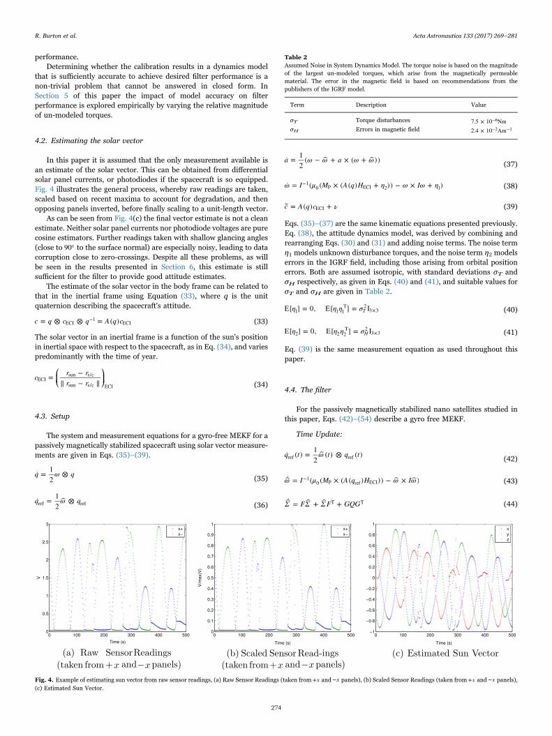
In this paper it is assumed that the only measurement available isan estimate of the solar vector. This can be obtained from differentialsolar panel currents, or photodiodes if the spacecraft is so equipped.Fig. 4 illustrates the general process, whereby raw readings are taken,scaled based on recent maxima to account for degradation, and thenopposing panels inverted, before finally scaling to a unit-length vector.
As can be seen from Fig. 4(c) the final vector estimate is not a cleanestimate. Neither solar panel currents nor photodiode voltages are purecosine estimators. Further readings taken with shallow glancing angles(close to 90o to the surface normal) are especially noisy, leading to datacorruption close to zero-crossings. Despite all these problems, as willbe seen in the results presented in Section 6, this estimate is stillsufficient for the filter to provide good attitude estimates.
The estimate of the solar vector in the body frame can be related tothat in the inertial frame using Equation (33), where q is the unitquaternion describing the spacecraft's attitude.
c q c q A q c= ⊗ ⊗ = ( )ECI−1
ECI (33)
The solar vector in an inertial frame is a function of the sun's positionin inertial space with respect to the spacecraft, as in Eq. (34), and variespredominantly with the time of year.
⎛⎝⎜
⎞⎠⎟c r r
r r= −
∥ − ∥ECIsun s/c
sun s/c ECI (34)
4.3. Setup
The system and measurement equations for a gyro-free MEKF for apassively magnetically stabilized spacecraft using solar vector measure-ments are given in Eqs. (35)–(39).
q ω q˙ = 12
⊗(35)
q ω q˙ = 12
⊗ref ref (36)
a ω ω a ω ω˙ = 12
( − + × ( + ))(37)
ω I μ M A q H η ω Iω η˙ = ( ( × ( ( ) + )) − × + )−10 P ECI 2 1 (38)
c A q c ν= ( ) +∼ECI (39)
Eqs. (35)–(37) are the same kinematic equations presented previously.Eq. (38), the attitude dynamics model, was derived by combining andrearranging Eqs. (30) and (31) and adding noise terms. The noise termη1 models unknown disturbance torques, and the noise term η2 modelserrors in the IGRF field, including those arising from orbital positionerrors. Both are assumed isotropic, with standard deviations σT andσH respectively, as given in Eqs. (40) and (41), and suitable values forσT and σH are given in Table 2.
η η η σE[ ] = 0, E[ ] = IT1 1 1T 2
3×3 (40)
η η η σE[ ] = 0, E[ ] = IH2 2 2T 2
3×3 (41)
Eq. (39) is the same measurement equation as used throughout thispaper.
4.4. The filter
For the passively magnetically stabilized nano satellites studied inthis paper, Eqs. (42)–(54) describe a gyro free MEKF.
Time Update:
q t ω t q t˙ ( ) = 12
( ) ⊗ ( )ref ref (42)
ω I μ M A q H ω Iω˙ = ( ( × ( ( ) )) − × )−10 P ref ECI (43)
Σ FΣ Σ F GQG˙ = + +T T (44)
Fig. 4. Example of estimating sun vector from raw sensor readings, (a) Raw Sensor Readings (taken from x+ and x− panels), (b) Scaled Sensor Readings (taken from x+ and x− panels),(c) Estimated Sun Vector.
Table 2Assumed Noise in System Dynamics Model. The torque noise is based on the magnitudeof the largest un-modeled torques, which arise from the magnetically permeablematerial. The error in the magnetic field is based on recommendations from thepublishers of the IGRF model.
Term Description Value
σT Torque disturbances 7.5 × 10 Nm−6
σH Errors in magnetic field 2.4 × 10 Am−2 −1
R. Burton et al. Acta Astronautica 133 (2017) 269–281
274
⎡
⎣
⎢⎢⎢⎢⎢
⎤
⎦
⎥⎥⎥⎥⎥⎡
⎣⎢⎢⎢
⎤
⎦⎥⎥⎥
F t
aa
aω
ωa
ωω
ω
μ I M A q H I ω I Iω
( ) =
∂ ˙∂
∂ ˙∂
∂ ˙∂
∂ ˙∂
=− [ × ] 1
2I
2 [ × ][ ( ) × ] (−[ × ] + [ × ])
a ω a ω
a ω a ω
, ,
, ,
3×3
0−1
P ref ECI−1
(45)
⎡
⎣
⎢⎢⎢⎢⎢⎢
⎤
⎦
⎥⎥⎥⎥⎥⎥
⎡⎣⎢
⎤⎦⎥G
aη
aη
ωη
ωη
I μ I M=
∂ ˙∂
∂ ˙∂
∂ ˙∂
∂ ˙∂
=0 0
[ × ]a ω a ω
a ω a ω
1 , 2 ,
1 , 2 ,
3×3 3×3−1
0−1
P
(46)
⎡⎣⎢⎢
⎤⎦⎥⎥Q
σσ
=I 0
0 IT
H
23×3 3×3
3×32
3×3 (47)
Measurement Update:
⎡⎣⎢⎢
⎤⎦⎥⎥H
ca
cω
A q t c=∂∂
∂∂
= [2[ ( ( ) ) × ] 0 ]∼ ∼
ka ω a ω
k, ,
ref−
ECI 3×3(48)
K Σ t H H Σ t H R= ( ) ( ( ) + )k k k k k k− T − T −1
(49)
R σ= Ic2
3×3 (50)
⎡⎣⎢
⎤⎦⎥
aω K c A q t cΔ = ( − ( ( ) ) )∼k
kk k kref
−ECI
(51)
q t δq a q t( ) = ( ) ⊗ ( )k k kref+
ref− (52)
ω t ω ω t( ) = Δ + ( )k k k+ − (53)
Σ t K H Σ t( ) = (I − ) ( )k k k k+
6×6− (54)
4.5. Implementation notes
Eqs. (42) and (43) can be integrated using a Runge-Kutta 4th orderalgorithm, with time step chosen such that ωdt∥ ∥ ≪ 12 . AlthoughEq. (44) can be integrated as written, maintaining Σ to be positive
definite requires ad hoc matrix re-projections. Instead, the estimate ofthe covariance matrix can be updated using a state transition matrix asin Eq. (55), which maintains Σ > 0.
∫Σ t Φ Σ t Φ G τ Q τ G τ dτ( ) = ( ) + ( ) ( ) ( )t t t tt
t1 , 0 ,
T T0 1 0 1
0
1
(55)
The state transition matrix Φ is computed using Eq. (56).
Φ F t t t= exp( ( )( − ))t t, 0 1 00 1 (56)
5. Results in simulation
In this section the filter derived in Section 4 is tested in simulation,before application to real flight data in Section 6. The simulationmirrors the conditions experienced by the satellites studied: a 650 kmaltitude low earth orbit at 72° inclination.
5.1. Nominal results
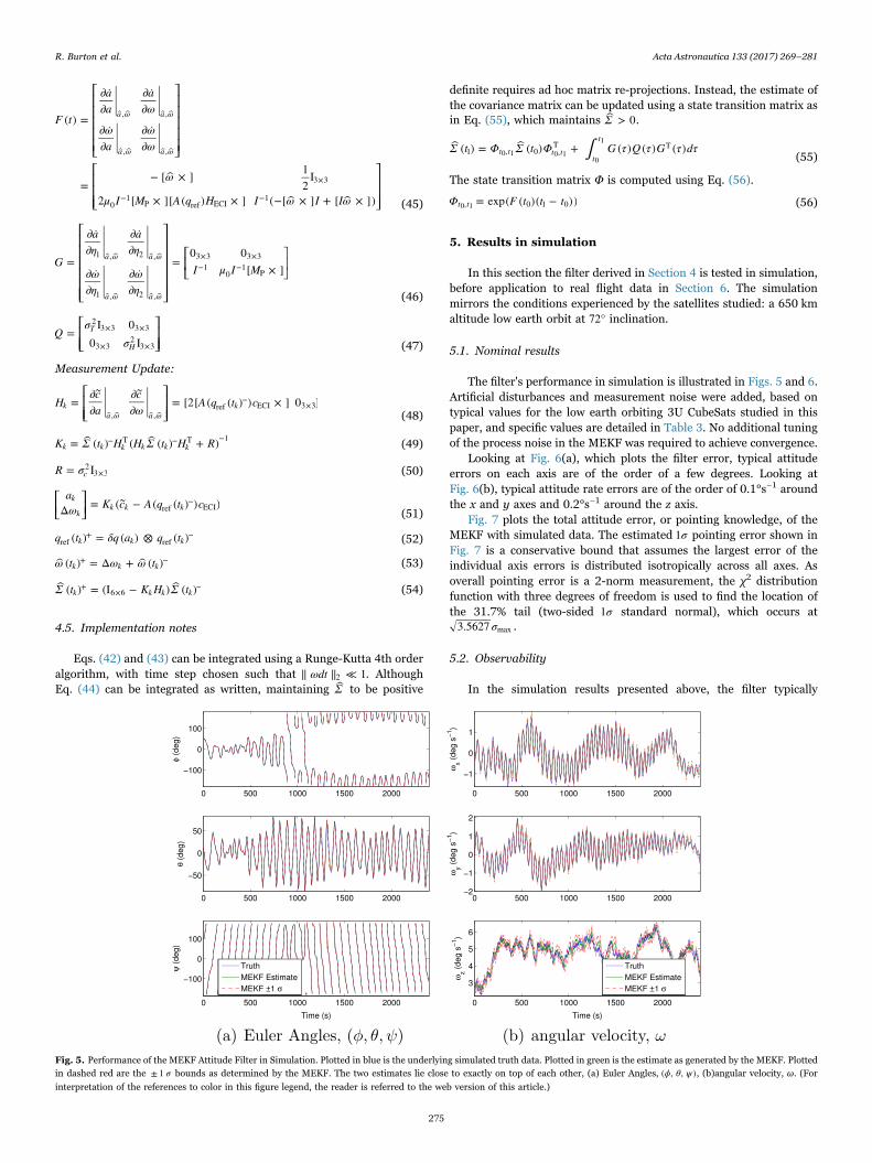
The filter's performance in simulation is illustrated in Figs. 5 and 6.Artificial disturbances and measurement noise were added, based ontypical values for the low earth orbiting 3U CubeSats studied in thispaper, and specific values are detailed in Table 3. No additional tuningof the process noise in the MEKF was required to achieve convergence.
Looking at Fig. 6(a), which plots the filter error, typical attitudeerrors on each axis are of the order of a few degrees. Looking atFig. 6(b), typical attitude rate errors are of the order of 0.1°s−1 aroundthe x and y axes and 0.2°s−1 around the z axis.
Fig. 7 plots the total attitude error, or pointing knowledge, of theMEKF with simulated data. The estimated σ1 pointing error shown inFig. 7 is a conservative bound that assumes the largest error of theindividual axis errors is distributed isotropically across all axes. Asoverall pointing error is a 2-norm measurement, the χ2 distributionfunction with three degrees of freedom is used to find the location ofthe 31.7% tail (two-sided σ1 standard normal), which occurs at
σ3.5627 max .
5.2. Observability
In the simulation results presented above, the filter typically
Fig. 5. Performance of the MEKF Attitude Filter in Simulation. Plotted in blue is the underlying simulated truth data. Plotted in green is the estimate as generated by the MEKF. Plottedin dashed red are the σ± 1 bounds as determined by the MEKF. The two estimates lie close to exactly on top of each other, (a) Euler Angles, ϕ θ ψ( , , ), (b)angular velocity, ω. (For
interpretation of the references to color in this figure legend, the reader is referred to the web version of this article.)
R. Burton et al. Acta Astronautica 133 (2017) 269–281
275
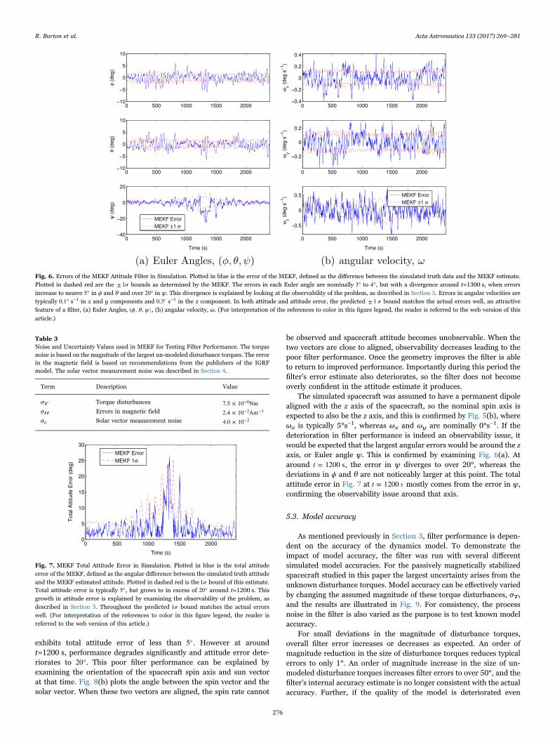
exhibits total attitude error of less than 5°. However at aroundt=1200 s, performance degrades significantly and attitude error dete-riorates to 20°. This poor filter performance can be explained byexamining the orientation of the spacecraft spin axis and sun vectorat that time. Fig. 8(b) plots the angle between the spin vector and thesolar vector. When these two vectors are aligned, the spin rate cannot
be observed and spacecraft attitude becomes unobservable. When thetwo vectors are close to aligned, observability decreases leading to thepoor filter performance. Once the geometry improves the filter is ableto return to improved performance. Importantly during this period thefilter's error estimate also deteriorates, so the filter does not becomeoverly confident in the attitude estimate it produces.
The simulated spacecraft was assumed to have a permanent dipolealigned with the z axis of the spacecraft, so the nominal spin axis isexpected to also be the z axis, and this is confirmed by Fig. 5(b), whereωz is typically 5°s−1, whereas ωx and ωy are nominally 0°s−1. If thedeterioration in filter performance is indeed an observability issue, itwould be expected that the largest angular errors would be around the zaxis, or Euler angle ψ. This is confirmed by examining Fig. 6(a). Ataround t = 1200 s, the error in ψ diverges to over 20°, whereas thedeviations in ϕ and θ are not noticeably larger at this point. The totalattitude error in Fig. 7 at t = 1200 s mostly comes from the error in ψ,confirming the observability issue around that axis.
5.3. Model accuracy
As mentioned previously in Section 3, filter performance is depen-dent on the accuracy of the dynamics model. To demonstrate theimpact of model accuracy, the filter was run with several differentsimulated model accuracies. For the passively magnetically stabilizedspacecraft studied in this paper the largest uncertainty arises from theunknown disturbance torques. Model accuracy can be effectively variedby changing the assumed magnitude of these torque disturbances, σT,and the results are illustrated in Fig. 9. For consistency, the processnoise in the filter is also varied as the purpose is to test known modelaccuracy.
For small deviations in the magnitude of disturbance torques,overall filter error increases or decreases as expected. An order ofmagnitude reduction in the size of disturbance torques reduces typicalerrors to only 1°. An order of magnitude increase in the size of un-modeled disturbance torques increases filter errors to over 50°, and thefilter's internal accuracy estimate is no longer consistent with the actualaccuracy. Further, if the quality of the model is deteriorated even
Fig. 6. Errors of the MEKF Attitude Filter in Simulation. Plotted in blue is the error of the MEKF, defined as the difference between the simulated truth data and the MEKF estimate.Plotted in dashed red are the σ± 1 bounds as determined by the MEKF. The errors in each Euler angle are nominally 3° to 4°, but with a divergence around t=1300 s, when errorsincrease to nearer 5° in ϕ and θ and over 20° in ψ. This divergence is explained by looking at the observability of the problem, as described in Section 5. Errors in angular velocities aretypically 0.1° s−1 in x and y components and 0.3° s−1 in the z component. In both attitude and attitude error, the predicted σ± 1 bound matches the actual errors well, an attractivefeature of a filter, (a) Euler Angles, ϕ θ ψ( , , ), (b) angular velocity, ω. (For interpretation of the references to color in this figure legend, the reader is referred to the web version of this
article.)
Table 3Noise and Uncertainty Values used in MEKF for Testing Filter Performance. The torquenoise is based on the magnitude of the largest un-modeled disturbance torques. The errorin the magnetic field is based on recommendations from the publishers of the IGRFmodel. The solar vector measurement noise was described in Section 4.
Term Description Value
σT Torque disturbances 7.5 × 10 Nm−6
σH Errors in magnetic field 2.4 × 10 Am−2 −1
σc Solar vector measurement noise 4.0 × 10⁻²
Fig. 7. MEKF Total Attitude Error in Simulation. Plotted in blue is the total attitudeerror of the MEKF, defined as the angular difference between the simulated truth attitudeand the MEKF estimated attitude. Plotted in dashed red is the σ1 bound of this estimate.Total attitude error is typically 5°, but grows to in excess of 20° around t=1200 s. Thisgrowth in attitude error is explained by examining the observability of the problem, asdescribed in Section 5. Throughout the predicted σ1 bound matches the actual errorswell. (For interpretation of the references to color in this figure legend, the reader isreferred to the web version of this article.)
R. Burton et al. Acta Astronautica 133 (2017) 269–281
276
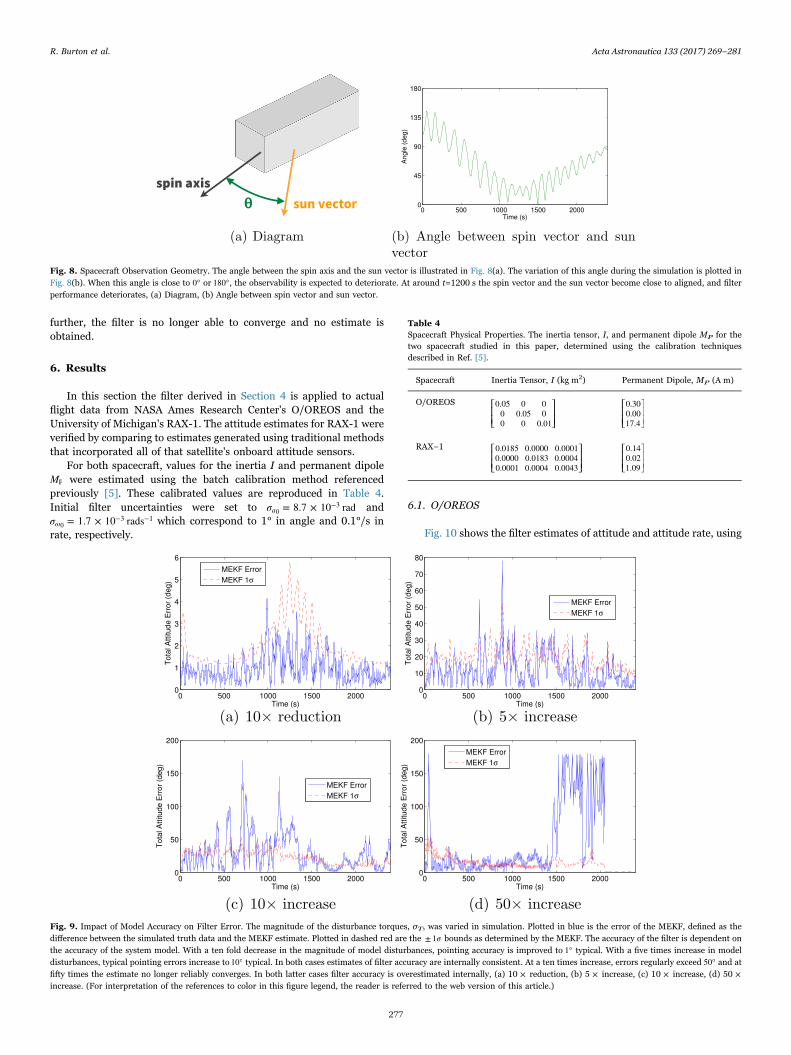
further, the filter is no longer able to converge and no estimate isobtained.
6. Results
In this section the filter derived in Section 4 is applied to actualflight data from NASA Ames Research Center's O/OREOS and theUniversity of Michigan's RAX-1. The attitude estimates for RAX-1 wereverified by comparing to estimates generated using traditional methodsthat incorporated all of that satellite's onboard attitude sensors.
For both spacecraft, values for the inertia I and permanent dipoleMP were estimated using the batch calibration method referencedpreviously [5]. These calibrated values are reproduced in Table 4.Initial filter uncertainties were set to σ = 8.7 × 10 rada
−30 and
σ = 1.7 × 10 radsω−3 −1
0 which correspond to 1° in angle and 0.1°/s inrate, respectively.
6.1. O/OREOS
Fig. 10 shows the filter estimates of attitude and attitude rate, using
Fig. 8. Spacecraft Observation Geometry. The angle between the spin axis and the sun vector is illustrated in Fig. 8(a). The variation of this angle during the simulation is plotted inFig. 8(b). When this angle is close to 0° or 180°, the observability is expected to deteriorate. At around t=1200 s the spin vector and the sun vector become close to aligned, and filterperformance deteriorates, (a) Diagram, (b) Angle between spin vector and sun vector.
Fig. 9. Impact of Model Accuracy on Filter Error. The magnitude of the disturbance torques, σT, was varied in simulation. Plotted in blue is the error of the MEKF, defined as thedifference between the simulated truth data and the MEKF estimate. Plotted in dashed red are the σ± 1 bounds as determined by the MEKF. The accuracy of the filter is dependent onthe accuracy of the system model. With a ten fold decrease in the magnitude of model disturbances, pointing accuracy is improved to 1° typical. With a five times increase in modeldisturbances, typical pointing errors increase to 10° typical. In both cases estimates of filter accuracy are internally consistent. At a ten times increase, errors regularly exceed 50° and atfifty times the estimate no longer reliably converges. In both latter cases filter accuracy is overestimated internally, (a) 10 × reduction, (b) 5 × increase, (c) 10 × increase, (d) 50 ×increase. (For interpretation of the references to color in this figure legend, the reader is referred to the web version of this article.)
Table 4Spacecraft Physical Properties. The inertia tensor, I, and permanent dipole MP for thetwo spacecraft studied in this paper, determined using the calibration techniquesdescribed in Ref. [5].
Spacecraft Inertia Tensor, I (kg m2) Permanent Dipole, MP (A m)
O/OREOS ⎡⎣⎢⎢
⎤⎦⎥⎥
0.05 0 00 0.05 00 0 0.01
⎡⎣⎢⎢
⎤⎦⎥⎥
0.300.0017.4
RAX−1 ⎡⎣⎢⎢
⎤⎦⎥⎥
0.0185 0.0000 0.00010.0000 0.0183 0.00040.0001 0.0004 0.0043
⎡⎣⎢⎢
⎤⎦⎥⎥
0.140.021.09
R. Burton et al. Acta Astronautica 133 (2017) 269–281
277
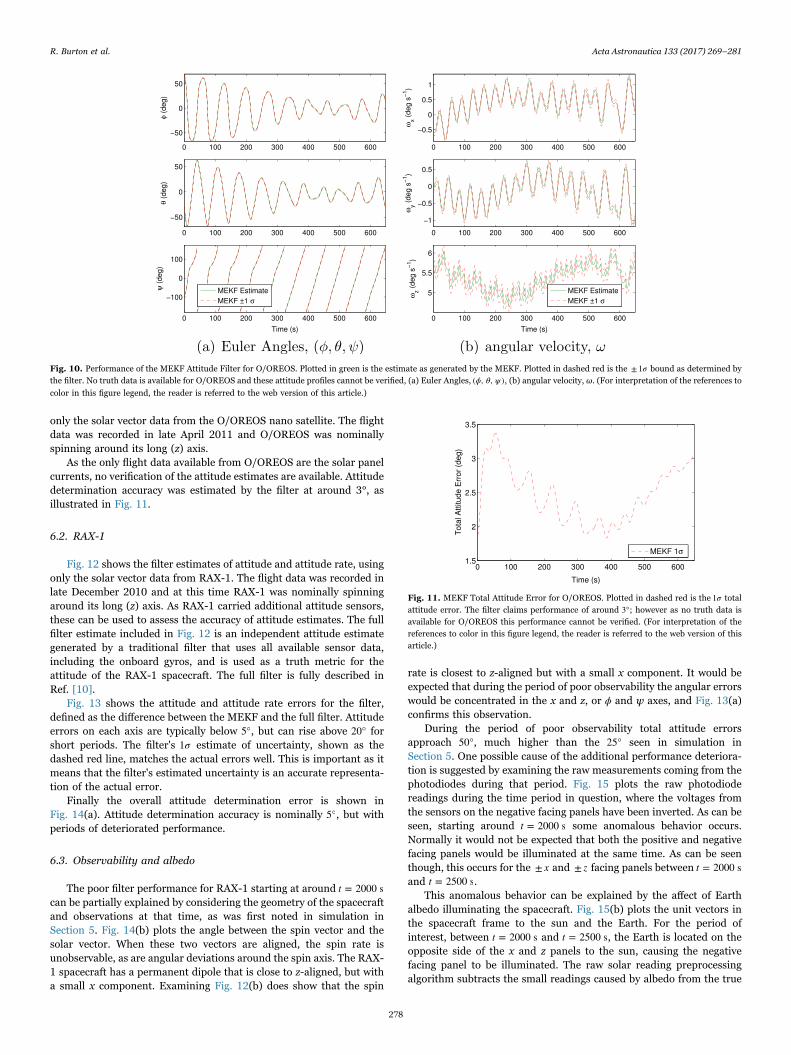
only the solar vector data from the O/OREOS nano satellite. The flightdata was recorded in late April 2011 and O/OREOS was nominallyspinning around its long (z) axis.
As the only flight data available from O/OREOS are the solar panelcurrents, no verification of the attitude estimates are available. Attitudedetermination accuracy was estimated by the filter at around 3°, asillustrated in Fig. 11.
6.2. RAX-1
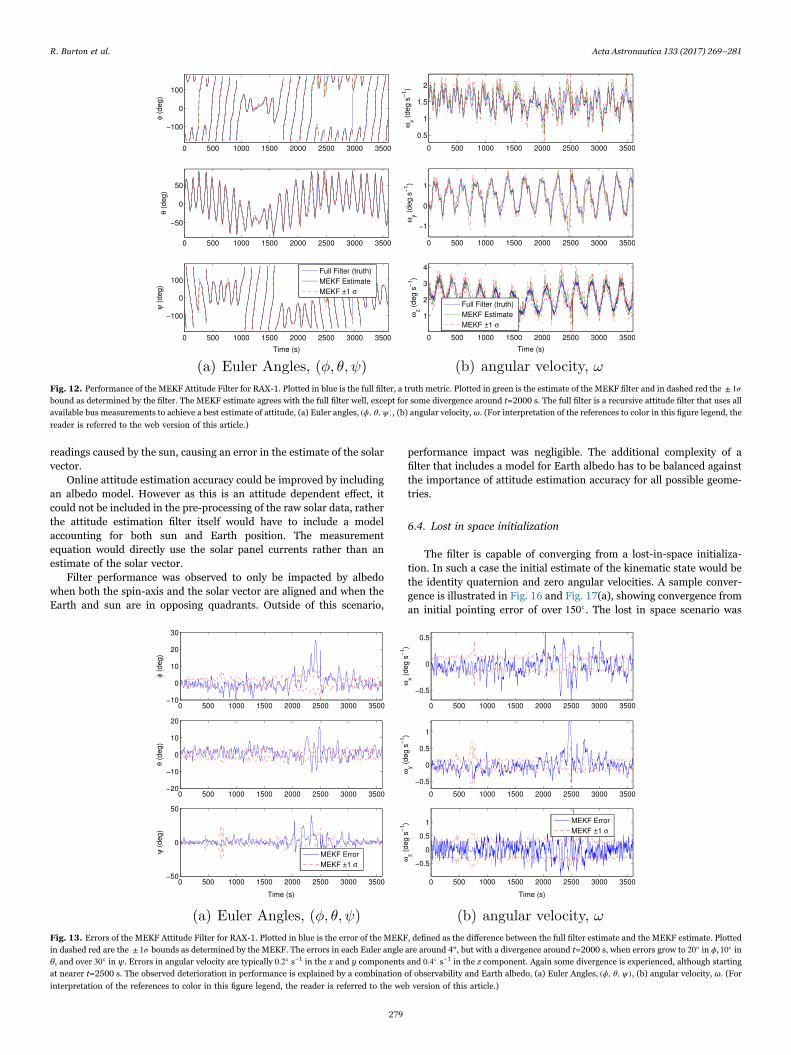
Fig. 12 shows the filter estimates of attitude and attitude rate, usingonly the solar vector data from RAX-1. The flight data was recorded inlate December 2010 and at this time RAX-1 was nominally spinningaround its long (z) axis. As RAX-1 carried additional attitude sensors,these can be used to assess the accuracy of attitude estimates. The fullfilter estimate included in Fig. 12 is an independent attitude estimategenerated by a traditional filter that uses all available sensor data,including the onboard gyros, and is used as a truth metric for theattitude of the RAX-1 spacecraft. The full filter is fully described inRef. [10].
Fig. 13 shows the attitude and attitude rate errors for the filter,defined as the difference between the MEKF and the full filter. Attitudeerrors on each axis are typically below 5°, but can rise above 20° forshort periods. The filter's σ1 estimate of uncertainty, shown as thedashed red line, matches the actual errors well. This is important as itmeans that the filter's estimated uncertainty is an accurate representa-tion of the actual error.
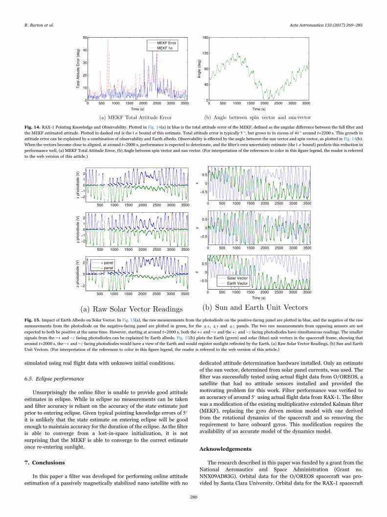
Finally the overall attitude determination error is shown inFig. 14(a). Attitude determination accuracy is nominally 5°, but withperiods of deteriorated performance.
6.3. Observability and albedo
The poor filter performance for RAX-1 starting at around t = 2000 scan be partially explained by considering the geometry of the spacecraftand observations at that time, as was first noted in simulation inSection 5. Fig. 14(b) plots the angle between the spin vector and thesolar vector. When these two vectors are aligned, the spin rate isunobservable, as are angular deviations around the spin axis. The RAX-1 spacecraft has a permanent dipole that is close to z-aligned, but witha small x component. Examining Fig. 12(b) does show that the spin
rate is closest to z-aligned but with a small x component. It would beexpected that during the period of poor observability the angular errorswould be concentrated in the x and z, or ϕ and ψ axes, and Fig. 13(a)confirms this observation.
During the period of poor observability total attitude errorsapproach 50°, much higher than the 25° seen in simulation inSection 5. One possible cause of the additional performance deteriora-tion is suggested by examining the raw measurements coming from thephotodiodes during that period. Fig. 15 plots the raw photodiodereadings during the time period in question, where the voltages fromthe sensors on the negative facing panels have been inverted. As can beseen, starting around t = 2000 s some anomalous behavior occurs.Normally it would not be expected that both the positive and negativefacing panels would be illuminated at the same time. As can be seenthough, this occurs for the x± and z± facing panels between t = 2000 sand t = 2500 s.
This anomalous behavior can be explained by the affect of Earthalbedo illuminating the spacecraft. Fig. 15(b) plots the unit vectors inthe spacecraft frame to the sun and the Earth. For the period ofinterest, between t = 2000 s and t = 2500 s, the Earth is located on theopposite side of the x and z panels to the sun, causing the negativefacing panel to be illuminated. The raw solar reading preprocessingalgorithm subtracts the small readings caused by albedo from the true
Fig. 10. Performance of the MEKF Attitude Filter for O/OREOS. Plotted in green is the estimate as generated by the MEKF. Plotted in dashed red is the σ± 1 bound as determined bythe filter. No truth data is available for O/OREOS and these attitude profiles cannot be verified, (a) Euler Angles, ϕ θ ψ( , , ), (b) angular velocity, ω. (For interpretation of the references to
color in this figure legend, the reader is referred to the web version of this article.)
Fig. 11. MEKF Total Attitude Error for O/OREOS. Plotted in dashed red is the σ1 totalattitude error. The filter claims performance of around 3°; however as no truth data isavailable for O/OREOS this performance cannot be verified. (For interpretation of thereferences to color in this figure legend, the reader is referred to the web version of thisarticle.)
R. Burton et al. Acta Astronautica 133 (2017) 269–281
278
readings caused by the sun, causing an error in the estimate of the solarvector.
Online attitude estimation accuracy could be improved by includingan albedo model. However as this is an attitude dependent effect, itcould not be included in the pre-processing of the raw solar data, ratherthe attitude estimation filter itself would have to include a modelaccounting for both sun and Earth position. The measurementequation would directly use the solar panel currents rather than anestimate of the solar vector.
Filter performance was observed to only be impacted by albedowhen both the spin-axis and the solar vector are aligned and when theEarth and sun are in opposing quadrants. Outside of this scenario,
performance impact was negligible. The additional complexity of afilter that includes a model for Earth albedo has to be balanced againstthe importance of attitude estimation accuracy for all possible geome-tries.
6.4. Lost in space initialization
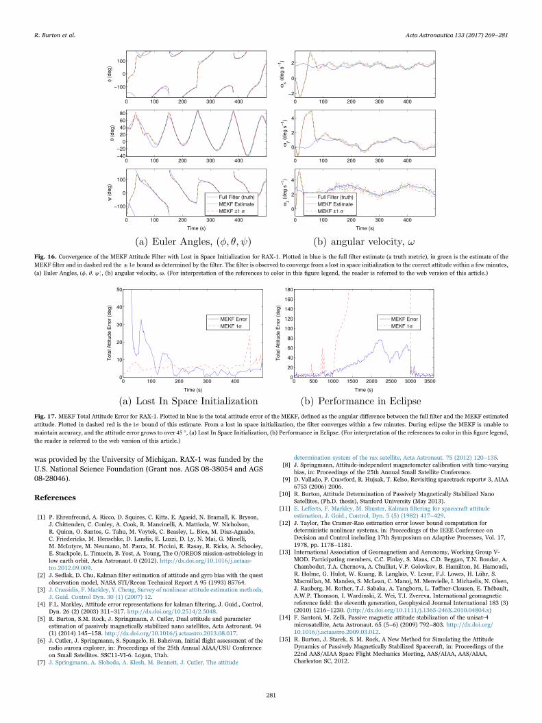
The filter is capable of converging from a lost-in-space initializa-tion. In such a case the initial estimate of the kinematic state would bethe identity quaternion and zero angular velocities. A sample conver-gence is illustrated in Fig. 16 and Fig. 17(a), showing convergence froman initial pointing error of over 150°. The lost in space scenario was
Fig. 12. Performance of the MEKF Attitude Filter for RAX-1. Plotted in blue is the full filter, a truth metric. Plotted in green is the estimate of the MEKF filter and in dashed red the σ± 1bound as determined by the filter. The MEKF estimate agrees with the full filter well, except for some divergence around t=2000 s. The full filter is a recursive attitude filter that uses allavailable bus measurements to achieve a best estimate of attitude, (a) Euler angles, ϕ θ ψ( , , ), (b) angular velocity, ω. (For interpretation of the references to color in this figure legend, the
reader is referred to the web version of this article.)
Fig. 13. Errors of the MEKF Attitude Filter for RAX-1. Plotted in blue is the error of the MEKF, defined as the difference between the full filter estimate and the MEKF estimate. Plottedin dashed red are the σ± 1 bounds as determined by the MEKF. The errors in each Euler angle are around 4°, but with a divergence around t=2000 s, when errors grow to 20° in ϕ,10° inθ, and over 30° in ψ. Errors in angular velocity are typically 0.2° s−1 in the x and y components and 0.4° s−1 in the z component. Again some divergence is experienced, although startingat nearer t=2500 s. The observed deterioration in performance is explained by a combination of observability and Earth albedo, (a) Euler Angles, ϕ θ ψ( , , ), (b) angular velocity, ω. (Forinterpretation of the references to color in this figure legend, the reader is referred to the web version of this article.)
R. Burton et al. Acta Astronautica 133 (2017) 269–281
279
simulated using real flight data with unknown initial conditions.
6.5. Eclipse performance
Unsurprisingly the online filter is unable to provide good attitudeestimates in eclipse. While in eclipse no measurements can be takenand filter accuracy is reliant on the accuracy of the state estimate justprior to entering eclipse. Given typical pointing knowledge errors of 5°it is unlikely that the state estimate on entering eclipse will be goodenough to maintain accuracy for the duration of the eclipse. As the filteris able to converge from a lost-in-space initialization, it is notsurprising that the MEKF is able to converge to the correct estimateonce re-entering sunlight.
7. Conclusions
In this paper a filter was developed for performing online attitudeestimation of a passively magnetically stabilized nano satellite with no
dedicated attitude determination hardware installed. Only an estimateof the sun vector, determined from solar panel currents, was used. Thefilter was successfully tested using actual flight data from O/OREOS, asatellite that had no attitude sensors installed and provided themotivating problem for this work. Filter performance was verified toan accuracy of around 5° using actual flight data from RAX-1. The filterwas a modification of the existing multiplicative extended Kalman filter(MEKF), replacing the gyro driven motion model with one derivedfrom the rotational dynamics of the spacecraft and so removing therequirement to have onboard gyros. This modification requires theavailability of an accurate model of the dynamics model.
Acknowledgements
The research described in this paper was funded by a grant from theNational Aeronautics and Space Administration (Grant no.NNX09AD83G). Orbital data for the O/OREOS spacecraft was pro-vided by Santa Clara University. Orbital data for the RAX-1 spacecraft
Fig. 14. RAX-1 Pointing Knowledge and Observability. Plotted in Fig. 14(a) in blue is the total attitude error of the MEKF, defined as the angular difference between the full filter andthe MEKF estimated attitude. Plotted in dashed red is the σ1 bound of this estimate. Total attitude error is typically 5 °, but grows to in excess of 40 ° around t=2200 s. This growth inattitude error can be explained by a combination of observability and Earth albedo. Observability is effected by the angle between the sun vector and spin vector, as plotted in Fig. 14(b).When the vectors become close to aligned, at around t=2000 s, performance is expected to deteriorate, and the filter's own uncertainty estimate (the σ1 bound) predicts this reduction inperformance well, (a) MEKF Total Attitude Error, (b) Angle between spin vector and sun vector. (For interpretation of the references to color in this figure legend, the reader is referredto the web version of this article.)
Fig. 15. Impact of Earth Albedo on Solar Vector. In Fig. 15(a), the raw measurements from the photodiode on the positive-facing panel are plotted in blue, and the negative of the rawmeasurements from the photodiode on the negative-facing panel are plotted in green, for the x± , y± and z± panels. The two raw measurements from opposing sensors are not
expected to both be positive at the same time. However, starting at around t=2000 s, both the x+ and x− and the z+ and z− facing photodiodes have simultaneous readings. The smallersignals from the x− and z− facing photodiodes can be explained by Earth albedo. Fig. 15(b) plots the Earth (green) and solar (blue) unit vectors in the spacecraft frame, showing thataround t=2000 s, the x− and z− facing photodiodes would have a view of the Earth and would register sunlight reflected by the Earth, (a) Raw Solar Vector Readings, (b) Sun and EarthUnit Vectors. (For interpretation of the references to color in this figure legend, the reader is referred to the web version of this article.)
R. Burton et al. Acta Astronautica 133 (2017) 269–281
280
was provided by the University of Michigan. RAX-1 was funded by theU.S. National Science Foundation (Grant nos. AGS 08-38054 and AGS08-28046).
References
[1] P. Ehrenfreund, A. Ricco, D. Squires, C. Kitts, E. Agasid, N. Bramall, K. Bryson,J. Chittenden, C. Conley, A. Cook, R. Mancinelli, A. Mattioda, W. Nicholson,R. Quinn, O. Santos, G. Tahu, M. Voytek, C. Beasley, L. Bica, M. Diaz-Aguado,C. Friedericks, M. Henschke, D. Landis, E. Luzzi, D. Ly, N. Mai, G. Minelli,M. McIntyre, M. Neumann, M. Parra, M. Piccini, R. Rasay, R. Ricks, A. Schooley,E. Stackpole, L. Timucin, B. Yost, A. Young, The O/OREOS mission-astrobiology inlow earth orbit, Acta Astronaut. 0 (2012). http://dx.doi.org/10.1016/j.actaas-tro.2012.09.009.
[2] J. Sedlak, D. Chu, Kalman filter estimation of attitude and gyro bias with the questobservation model, NASA STI/Recon Technical Report A 95 (1993) 85764.
[3] J. Crassidis, F. Markley, Y. Cheng, Survey of nonlinear attitude estimation methods,J. Guid. Control Dyn. 30 (1) (2007) 12.
[4] F.L. Markley, Attitude error representations for kalman filtering, J. Guid., Control,Dyn. 26 (2) (2003) 311–317. http://dx.doi.org/10.2514/2.5048.
[5] R. Burton, S.M. Rock, J. Springmann, J. Cutler, Dual attitude and parameterestimation of passively magnetically stabilized nano satellites, Acta Astronaut. 94(1) (2014) 145–158. http://dx.doi.org/10.1016/j.actaastro.2013.08.017.
[6] J. Cutler, J. Springmann, S. Spangelo, H. Bahcivan, Initial flight assessment of theradio aurora explorer, in: Proceedings of the 25th Annual AIAA/USU Conferenceon Small Satellites. SSC11-VI-6. Logan, Utah.
[7] J. Springmann, A. Sloboda, A. Klesh, M. Bennett, J. Cutler, The attitude
determination system of the rax satellite, Acta Astronaut. 75 (2012) 120–135.[8] J. Springmann, Attitude-independent magnetometer calibration with time-varying
bias, in: Proceedings of the 25th Annual Small Satellite Conference.[9] D. Vallado, P. Crawford, R. Hujsak, T. Kelso, Revisiting spacetrack report# 3, AIAA
6753 (2006) 2006.[10] R. Burton, Attitude Determination of Passively Magnetically Stabilized Nano
Satellites, (Ph.D. thesis), Stanford University (May 2013).[11] E. Lefferts, F. Markley, M. Shuster, Kalman filtering for spacecraft attitude
estimation, J. Guid., Control, Dyn. 5 (5) (1982) 417–429.[12] J. Taylor, The Cramer-Rao estimation error lower bound computation for
deterministic nonlinear systems, in: Proceedings of the IEEE Conference onDecision and Control including 17th Symposium on Adaptive Processes, Vol. 17,1978, pp. 1178–1181.
[13] International Association of Geomagnetism and Aeronomy, Working Group V-MOD. Participating members, C.C. Finlay, S. Maus, C.D. Beggan, T.N. Bondar, A.Chambodut, T.A. Chernova, A. Chulliat, V.P. Golovkov, B. Hamilton, M. Hamoudi,R. Holme, G. Hulot, W. Kuang, B. Langlais, V. Lesur, F.J. Lowes, H. Lühr, S.Macmillan, M. Mandea, S. McLean, C. Manoj, M. Menvielle, I. Michaelis, N. Olsen,J. Rauberg, M. Rother, T.J. Sabaka, A. Tangborn, L. Tøffner-Clausen, E. Thébault,A.W.P. Thomson, I. Wardinski, Z. Wei, T.I. Zvereva, International geomagneticreference field: the eleventh generation, Geophysical Journal International 183 (3)(2010) 1216–1230. ⟨http://dx.doi.org/10.1111/j.1365-246X.2010.04804.x⟩
[14] F. Santoni, M. Zelli, Passive magnetic attitude stabilization of the unisat-4microsatellite, Acta Astronaut. 65 (5–6) (2009) 792–803. http://dx.doi.org/10.1016/j.actaastro.2009.03.012.
[15] R. Burton, J. Starek, S. M. Rock, A New Method for Simulating the AttitudeDynamics of Passively Magnetically Stabilized Spacecraft, in: Proceedings of the22nd AAS/AIAA Space Flight Mechanics Meeting, AAS/AIAA, AAS/AIAA,Charleston SC, 2012.
Fig. 16. Convergence of the MEKF Attitude Filter with Lost in Space Initialization for RAX-1. Plotted in blue is the full filter estimate (a truth metric), in green is the estimate of theMEKF filter and in dashed red the σ± 1 bound as determined by the filter. The filter is observed to converge from a lost in space initialization to the correct attitude within a few minutes,(a) Euler Angles, ϕ θ ψ( , , ), (b) angular velocity, ω. (For interpretation of the references to color in this figure legend, the reader is referred to the web version of this article.)
Fig. 17. MEKF Total Attitude Error for RAX-1. Plotted in blue is the total attitude error of the MEKF, defined as the angular difference between the full filter and the MEKF estimatedattitude. Plotted in dashed red is the σ1 bound of this estimate. From a lost in space initialization, the filter converges within a few minutes. During eclipse the MEKF is unable tomaintain accuracy, and the attitude error grows to over 45 °, (a) Lost In Space Initialization, (b) Performance in Eclipse. (For interpretation of the references to color in this figure legend,the reader is referred to the web version of this article.)
R. Burton et al. Acta Astronautica 133 (2017) 269–281
281