Embed Size (px)
Citation preview
n GENERAL RADIO -EXPERIMENTER
ELECTRICAL TECHNIQUE
MEASUREMENTS ~~
AND ITS INDUSTRIAL APPLICATIONS
VOL. XI No . 12 MAY, 1937
TYPE 726·A VACUUM·TUBE VOLTMETER .BECAUSE VOLTAGE MEAS · U REM E N T S at communication frc(lucncic6 usually require a voltmeter "ilh an input imperlallce so high as to
ha ve no appreciable shunting effect 0 11
the source under measurement , the vacuulIl- tube volt.meter is a laboratory necessity to the communica tion engillCt!r. Commercially ava ilable thermi. onic \·ol tmetcrs bave in general been subject to ODC or morc of the following defects: low sensitivity. limited voltage range. hi gh-frequency error, and limited precision of reading at 10 ..... va l·
ues 0 11 the seale. The design of II
voltmeter in which these defects a re minimized has recently been
completed. and, since it repre-se nts a new approach to Ibe problem of a-c voltage mea,,
urements, a number of il s design features a re wor th y of men lion. T he voltmeter consists of a fam iliar combiu a-tion ~ a diod e-condenser rec tifier cireuil and a doc amplifier. A condenser
beco mes charge(l b) the recti fier
FIC Ulu: I. Tn'~ 726·A Vacuum-Tube Vollrneler
IET LABS, Inc in the GenRad tradition
534 Main Street, Westbury, NY 11590 www.ietlabs.com
TEL: (516) 334-5959 • (800) 899-8438 • FAX: (516) 334-5988
'" '" .. =
c, .~ r,.-t-..,-:~r' --r-YV"'~I>M~ ' 'T-o
INPUT ~~ )
19;- '- Y fl. , C'T FI(,t .. I> :.> . Scl,,-rnati .. eir<:ui l diagn" n .. ( 11,,·
I _euu m _tuh .. ' Ul l m" lo'r
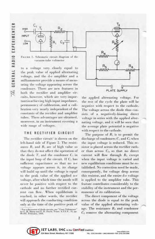
[0 II \'o lta ge H'r) clf)lw l, equal [ 0
the pea k \'81111.' o f ( 1)plietl altc rIl lllill J; vtlh age. a mi 1111" d-e Rmpl ifier a nd II
millin mmeLc.r pro, ide n means of tll t'ItS·
uring , lie ,oll age npl,o'aring across t ill'
('onden~cr. T lu:.rc li re II C' \ fe atll r(!11 111
bOlh tt." n -('ti ller Ull tl nmplificr cir I'u i l;;, hO\\ I.'I'l' r. ,, 1.i,,11 an' H: rr im po rta n t in adl ic\ ing h i:;h input irn pNl ulH't·.
lK' rIIla lle llC) of ea li hra ti(m. 8 1111 a ('a li. bra lion \ ' f"f) nCll rl~ illllcpc ndcril of til l'
COll8la niS or Ihe reeti fi ,- r and a mplifier luhcs. Thes,- adva nt ages are oLla illl" !. moreover, in li n ins tru ment co veri ng It
wirlc ra nge of volta ~,·s.
T HE RECT IFIER CIRCUIT
T Ile rel' lifier ('i r"uil ' is "howil uII 11 .t' Ich·hand side of Figure 2. The resi81· II nceti Il . a llli U1 arc of high 1' lIlu(' tlO
Ihll t lI .e)' (10 no t IIffcc l Ihe opera I ion of the d imlt· 1'. 1111.1 11'11' "ondenser C. ill .111" illplll loop of the dr(' lIit. If C. hil S Auffic;"nl l"a pa(."i tOlnc(' 80 Iha l [10 a·(· • 'o lt ag" apl)Car!l al'ross it. ils cha rge \\i llimiid up un til ll.e \'o llage is eq llul 10 . he ' ... ·a k va lut' o f the a pplie(] a ·(· vollu ge. a rtcr whir h li ' lle the a nolle will never hc l.IOSili v.· Ilith reS ]Jccl 10 tilt" (·a ll.od., and no further rel' lific,1 Cllr· ren t call flo\\. Whe ll f'qui libriulII iSl r('lIehed. in Olher I>offl s. the rec t ifi er wi ll ll pproat'h tile cOlliluctiog cOlldiliml onl y lit the lime of the IlOSili,'c peak of
, ~'Of' dlocu .. "'ft or di"'I0.~ ..... ~, ... _ "C..,., Vol""".",," 11, C. II . s ..... p .ftd E. D. I)<'y le. T,.~ ., A.U :. t; .• 35. I' ''. " .107, F~b .... U)'. 1916.
2
T,
.. PLATE SUPPLY
1111' a pplie fl ul lcl"1I uting volla g'" For the reS I of t l1l" (') I" Ic tlw pl:ll e \\ ill be IIl'ga til e wi lh r(·tl j)C(·t to t he ,·a ll u}(ie. Till' \"olw ge a,'rOSA li lt' Iliotle t h \l ~ con· fliR t:. of a ncga til·cly ·biasing dirt'c l \ o ll age in seri('.e .. ill. the a pplic.l ulk r . nut ing loll age. li nd it \\' ill be secn Ihul Ihe H\'crage pl a le IHUt'nlia1 ill nCl-:a l il'e II i ll . resl)(, ,'1 10 I he cn I hode.
Thc Jluq KlSt' o f NL is to per mil t he discharge of l'omlenS('rs C1 a llfl C, \\ hf' 1L Ihe iop11 1 voltage is redul;e,1. T IL is rf'sistor is pla cetl across the reo.; tifi er ra th · er thun across Ct. 110 Iha l fl O tli rec t ('urre nt will n Oli Ihrol1glL U, except when the inpu t "'oh uge is vuried a nd
new equ ilihriul1l l'o ll tli tions IllLl lj t he I'S,
ta hli"he,!. No correc tion n(:cd he lIIade . consequent ly, {or voltage drop aerOM thi! resi5l or, anrl the entire d ·e volt age is a ppl ied to Ihe (lmpli fie r tube. T his fcn lLl re contrilJll tes cons idera bly to t he s la bi lity of 1111' inSlru men t a nflthe pe r · m,m ence of ils eali bra lion.
The direci component of Ihe voltage across the .Iiode i.e C(l tlal to Ihe peak va lue of Ihe appl ied a h ern a ling voll · age. The rtJs istance 1<2 and condense[ C2 remove the a h erna ting compone nt
IET LABS, Inc in the GenRad tradition
534 Main Street, Westbury, NY 11590 www.ietlabs.com
TEL: (516) 334-5959 • (800) 899-8438 • FAX: (516) 334-5988
so Ihal only the direct COlllpo lle ut is applied to the d-c a. rn plifit'r. Ela hora te hl-
.... lerill!; is lIo t nece8~aq .luc to tile e,; trcme linca ril yof I he 8111pl ifi er resul t · iu g fru m licgencration . Unless the al· Icrlll .. ing ,·oltage is suflicic nt to swin g the plnte current LO c.;u t -ofT, olily a negli gible Il lllount of reetificll tion can take place. The si mple filt erillg a rra ngemen t shOl. n is . therefore. en! ire ly adequat e.
THE AMPLIFIER CIRCUIT
Th~' II -e am pl ifiel' circ uit is slun' lI in the right -hand section of Fig llre 2. The rcsistor ill the cat hode lead is particularl) illl l)()rtant. This pro ,· ides (Iegenerative coupl ing IJeh.een the input a llli ou tput circuits a nd not on ly accom _ plishes in the d·c case im provements a nalogous to t hose resu lt iug from theu~'
of degeneratioll ill a-c a lllplifica t ion. ~
bul also has ot her important resu h s. Defore themall llerofol.lt!ration is ex-
.... plained, tile important ilu provemcn tii rcsulting from li lt' u:.e o f degeneration in the presen t case \\ill Lc outlined :
(a) The meter in dica tion "jthin ,Tery clO$e limits is malic propor tiona l to the direl· t voltagc introdu(:ed into the grid circuit.
(b) Th~ sensiti" it) is lIl ade prac.; ti ca ll y inde llCndent of the con"tants of the luhe.
(c) The gri d ei r.'II it is rcudcn::d cupa!'le of ha ndling Ili rcl't ly voltages hUlillrel ls o f limes greater tha n the nor mal 1'lIt ·off bi as. II cnre no ,Tollage_ dividing ne twork is re<wired.
(II) The ,;cnsili\ it) cun lie changed for the va rious desircil volwge ra nges mcrely by chunging LIII: va lue of the ca thode resistor and the "a llie of til(" grill·bias \ oltagc.
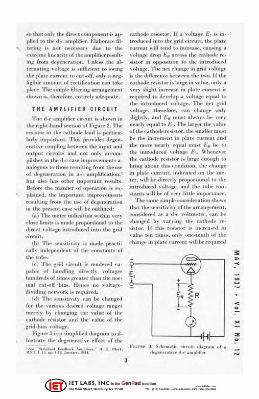
Figure 3 is a sim piif'ic(i diagram to iI · ... lus lrate the degcnerative effecL of t he
• s.. ".s,.bill.ttl f«d',.~k A", .. "f'cn>." II. S. III.,·~. II .S.1'. J . I~. 1>1>. 1·111. hnuo,l'. I~J I.
3
cuthode resis tor . If a volt age E, is in· troduced in to t ht' grill circuit. the platc currc nt will tend 10 increase. ca using a voltage drop En across the cathode re· sistor ill opposition to the introduced ,·ohll ge. The net c hunge in grid vol tage is tile d iffere nce be t \\ecn the L"O. If til ': ca thode resistor is la rge in ,' alue. onl y a \ cr) slight increase in plate current is re1luired 10 develop u ,oltage e(lual to Ihe introdu{:e(1 \oh age. T he ne t grid voltage. tllcrcfore, Cll n change onl) sliglllly, anll I:.'n II1I1S I a lwa ys be ver) nearly eqllult o 1::,. The larger the \ allli'
of the ca thode resiSlor, the smaller mus t be the increme nt in plate curre nl a nd the more nearly Nlua l must En be to the introdllced 'fllt ugc £ ,. Whc ne,cr the ca tit ()(le rt·siS lor is large enough to hrin g 11bollt th is condi tion, the chan ge ill plat e curren t. indicated on IllI" mcler. \\i ll be dircc.; tl, pruportional to the int rodut:eli ,ohage. Hilt! the tube I'ons tant s will he ur \cr) li tl le imj)Or tUlll'c .
The sa llie simple COllsideru lion sho\\ s t ha t the sclI l;.i ti\'i t) o f the arra ngt· luent . consillered IlS a ll·(· ,' oitll1cler, l'an be \·hangcd by ,nr) in g thc cathode rc· sis tor. If this resistor is illc.;rea~t1 in \'a luc It'll tilllcs. onl} line -tenth of the chulIgc ill pia I.e c urrCllt will be required
+
E, + 1:
L R
"' '':U" K 3. Schc",,,li,' "ircuit ,Iiallrllfll ,)r " ,I'·g'·ner"'i •• , ,1.,- jo lll l,lificr
< o
><
:z o
IET LABS, Inc in the GenRad tradition
534 Main Street, Westbury, NY 11590 www.ietlabs.com
TEL: (516) 334-5959 • (800) 899-8438 • FAX: (516) 334-5988
= = cC ~
to de"elop a given opposi ng "011 age. If the platc mjll iammeter hat! a cerl.ai n full-scale sensiti,' ity, consequent ly, tell limes the volt age III U8 t be in troducell in to the grid circuit to ca use fu ll -sca le deflection. For surlicielltly high va lues of the ca thode resistor, the full-seal.; voltage is directly propor tional to the ca thode resis ta nce and depends only on th is quanti ty and 0 11 t he sellsili"ity of the mill iam meter.
The polarity of the di rect voltage {Ievclo l>cd by the rectifier circui t and ap· pl ie(1 to the d-e amplifi er is such tlJut the grid of the amplifier 1'2 ill made neg· a ti ve with reSI:tCct to the ca thode. T his is impor tant in preventing damage to
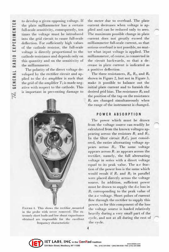
FIGU"!';~ . 'I'hi,. ShO" 8 the rec lifier, ,,,o,,,,ted ill the pro t.e ",itb cover rel"oved. T he Cl(
tcemdy ~hoct ielldllll nd 10'" shun t CIl[lIlcitllllce ohtaiued ace re.J I,olls ilJle {or the excellent
freq uency cbaracteri ~ tic
the rueter due to overload. The plate cu rrent decreases when voh age is applied a llli ca n be rellucud only to zero. T be max imulll possible change in pla te current does not great ly exceed the rni lJianllnet.cr fu ll·sra le current, so th at serious over load is not possible, uo IU8t· ter \\ hat inpu t voltage is appl ied. The milliamllie tcr, of course, is COllncctc(1 in the Cirf!uil hackwan ls, so tha t a decrease in pla te curren! is indi cateJ as a p08i ti\'e defl ect ion.
T he three resistances, R~, U~. and Ra sho\\'11 ill Figure 2, hut lIot in Fi gure 3, make it possible to bai:ulcc out Ihe initia l pla tc current and to furni sh the desired grid bias, The resisl.ance R~ alld the posiljon of the tap on the resis tance U, are clHtnged simultaneously whell the range of tbe instrument is cha nged.
POWER ABSORPTION
T he power which must be drawn (rolll the ,'olt age source can readily he calculated from the known volta ges appea ring ncross the resistors R, lind U2•
In the filter circuit R1C! just consid ered, the entire IIltenl li ti ug voltage ap-1>Cll rs across R~ . The sa me \'oltage apl:lCars across RI as apl:;ears across the rl'ctificr , namely. the full a lt erna tin g voltage in series wilh a di rect ,·oltage cqua l to it s peak \'li llie. The a-c fr action of t.he power loss is the Slime which \\'oultl res ul t if RI and III in parallel \\el·c placed directly across the volt age sou rce, In addition, sufficient po\\er IIlUSt he liraw il to supply t ile doc los8 in II I correspolIJing to the I>cak va lue of the a-c volt age. Shori pulses of f'urrell t fl ow through the rectifier to suppl y this power, so for this cOllq)Onenl of the loss lhe volt age souree is loaded rchlli vc ly he ll vil y {luring a very sll1all parI of the cyi'lc, and nol at all during the rest of Ihe cycle.
4
IET LABS, Inc in the GenRad tradition
534 Main Street, Westbury, NY 11590 www.ietlabs.com
TEL: (516) 334-5959 • (800) 899-8438 • FAX: (516) 334-5988
-DUll to th l! shortness and iu tensity of
the pulses through the rec tifier any resista nce in the input branch reduces seriously the fl ow of I'cct ificd current and lowers correspondin gly the meier reading. It is t his reduction in me ier readi ng d ue to the illl pcdaucc of the volt age source, rllther than the 10lal power consumption, whidl is import an t in mOIl! applica tions. This c lTCtJl ca ll he made negligi ble only by reducillg the d-e power absorbed 10 t he lowes t possible \'a luc. In the T YPE 721 . /\ Vacuum-Tube Voltmeter the rt!SiS IOr R , has the ,'al ue 50 megohm s. About ,~
IUcgolulIs in series wi th the app lied vol tage is sufficient. ho .... ,c \·er, to hah'e the volt meter readi ng. From the ,'olt · age reduction s tandpoi nt the input resistance, therefore, can be said to be 4 megohms. The I}()"'er absorption, howe \'cr. is del,ermi ned mainl y by a-c losses in R, (10 megohms), and fro Ul this stllndpoill l the inpu t resista nce is ap_ preciahly grea ter ~ about 6 megohms. At high frequc n,:ies o ther factors be· come imporHmt, so that the simple analysis here given is no longer appli cable. These faetors a re (Iiscussed below.
OPERATION AT HIGH FREQUENCIE S
T o ael lieve satisfactory opera tion at high frequencies, the e lellll!l1 ts which ma ke up Ihe rect ifier ci rcuit a re made as small as possible and are mou nted in a separate housing at the end of II fl exi.ble cord. Probe termin a ls arc pro"j.Jed so thai the measuring circuit Illay be placed d ose to lhe volta ge !murce, A 955-typc acorn tube is used as t he diode rectifier. The probe termina l! can be removed to reduce slill furthe r the induc tance of the inpu t loop_
As a result of these de ta ils of COil -
5
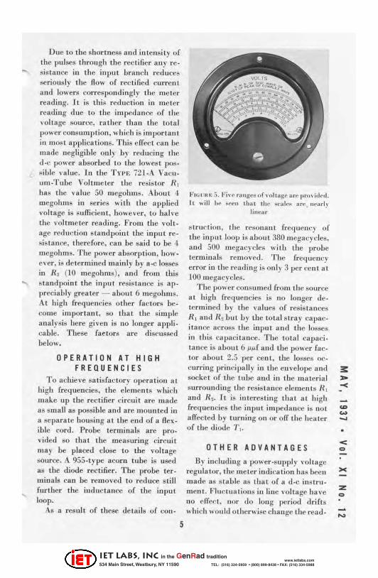
FIGIlIe ~ 5. Fi , t! 'Hllge" of vol tog~ or" 1"'" i.I,·,I. II will I,e ~,~" thal ,I". ~"III~.,. an: " N,d.,
lillc~r
struc t ion, Ihe reSOtHltl t {reque/ley of the input loop is abollL 380 megacycle,.. and 500 megacycles with the probe termi nals remove,l. T ile fre(IUency error in the read ing ;sonly 3 per ct;! lI lllt 100 megacycles.
The pOI' er consumed fro lll 1 he source at higu frequencies is no longer de. termined by the valucs of resistances RI and H.l bUI by tbe IOlal stray capacitallce across the input lind the losses in this ua pacita llcc. The to tal ca paci. tance i,. Ilbout 6 ~~f and tbe powcr faeLOr about 2.5 per ceut, t he losses occurring principa ll y in the e ll velope and socke t. of the tube and ill tbe ma terial surrounding tile resis t,ance clement s RI and Ih. It is interesting that a t high frequencies the input illlpeda llce is nol affectell by tu rn ing on or off the heal er of the diode "1',.
OTHER ADVANTA GE S
Dy including a power ·supply voltage regula tor, Ihe me ter indication has bec n made liS stable as that of a d_e ins trument. FluCLU a tious in line voltage have 110 e ffect , lIor do long per iod drifts 1\ hich would o tl,crwisechauge the rea d-
• < o
:z: o
IET LABS, Inc in the GenRad tradition
534 Main Street, Westbury, NY 11590 www.ietlabs.com
TEL: (516) 334-5959 • (800) 899-8438 • FAX: (516) 334-5988
mg Ihrough changt:1I ill filament tem· peralurt:.
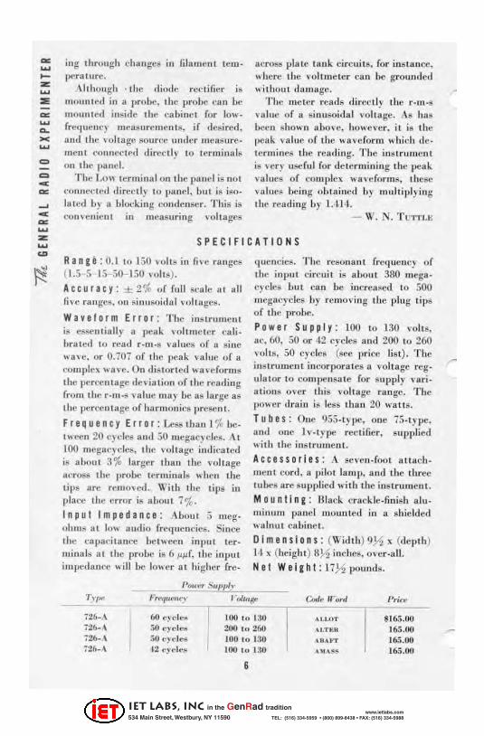
Although . the Iliode rcl'lifier is rnoun tt"ti in a probe, Ihe probe ca n bc mou nled in6idll Ihe cu binci for low· frc(llIclU') IlIeaSllrll lUenlS. if de8ired. anll the voltage source limier measure· ment l"OIlIIC(,ICll .Iircedy to terminals 0 11 the panel.
Tile LOI\ lerm inal on the panel i" not "ollnet:lctl,lireclly to pu nel, but i ~ iso. lat.ed b) n blocking cOlldel1ser. This is conH:nient in measuring vol tages
acrosll plat.e ta uk: circuits. for instance, I."here Ihe I'oit mcter ca ll be grollmled v.'ithou t d:ulluge.
The metcr reads di reetly the r ·III ·S va lue of a sinusoidal I'olt age. As hUll ()cell shown above, hOltCI·e r. it is thc pellk vu llle of the " 'ave form which de· termines the reudi ng. The instruillent is I'cry usefu l for lle terlll ining the lleak values of complex V. UIcform8, Iheac values bci ng uLt ll inell by multi pl) iug the readi ng Ly 1.4 14.
- W. N. T urn .a-;
S PE CIFICA TION S
Rang. : 0.110150 volt ,. in fil(: ranges (1.5 5 15 50- 150 lOllS).
Accuracy : ± 2% uf full sca le nt all five rangCII, on sinusoidul vul lug.·!!.
Waveform Error : The iuSLrUlllerH is essentia lly II pc-uk: \oltmeter cu li· braterl to read r · IIi·S I'a lues of a sine v.a\'e. or 0.707 of the peak: val lie nf a cOlllplc~ II a I e. On diSlort ed II a, cforll1S Ihe Ilerr!Clltage lie, ia tion of I he rcading from the r· III·S value lIlay be as 1urge as tile percentage of hUl'lIlonics prcsen t.
Frequency Error : Lcssthan 1% be· I II cen 20 e) eles und 50 mcgae) des. At 100 IIlcgacyclcs, the voltage inllit'at ed is aLoul :i% larger than the I'ohagc ucross thc probe terminals whell the lips are remO l ed. Wilh Ihe tips ill plaec the error is ahout i %. Inpul Impedance : Aboul 5 meg. ohms at low audio frequencies. Since Ihe capaeit8 1lt..'e hc tll ee n input ter · minals III Ihe prolJC is 6 !A!Af, Ihe input impedance will be lo\\cr at higher fre·
l 'tm..,,- supply
qllcncics. T he resonant freque ncy of the input circui t is abOllt 380 mega· ('yelcs bu t cun be increased 10 500 megacycles Ly removi ng the plllg l ips of tbe probe.
Power S uppl y: 100 10130 l'oh8. ne.60, 50 or 42 cycles and 200 to 260 volts, 50 t:ycles (sec price list ). The inSlrumen t incorporales II volt age reg· ulator to compensa te for supply I'ari· a liOIlS over Ihis volt age range. T he 1}OII er drain is less 1.1 11111 20 wailS.
T ub e s: Que 955.t) pc, one 75·type. and one lv·type rec lifier, supplied v.-illl the illSlrU lIlcnt.
Access or ie s: .A sewn·foot Ullllch· l1Ie1l1 cord, a pi lot lamp. and lhe Iluee tubes are sUPlllied wi tb the ins truUicnt.
M 0 u n t in g: Black crackle·fin isb alu· min um panel mounted ill a shie lded walnut cabi ne t.
Dim e n s i on s: (Widt h) 9,!A1 x (depth) }II x (height) 8H inches, OI'er ·a lL
Hel Wei ght : 17}2 I>ou nds.
'/ :I'I H' FretIIlC"C)' 1'0110(1' (;....1" "or,1 I'rj~'f'
72&·A 6() cydO!I! 100 I" 1:10 .I ... ,oT 8 16.') .00 72f •• ,\ 50 .. yde.'l 200 ,,, 260 \I.TIU' 165.11(1 726· \ 50e,dn 100 10 130 \lu .... 165.00 72h. \ 12 cy,·I'·1! 100 I .. 130 .1)1 \ ;;;; 165.00
G
IET LABS, Inc in the GenRad tradition
534 Main Street, Westbury, NY 11590 www.ietlabs.com
TEL: (516) 334-5959 • (800) 899-8438 • FAX: (516) 334-5988
-
MISCELLANY • 0 N MAY 1 ,fI.'lartill A. Gi lman joined the E:nginccring Department of the General nadio Compan y. Mr. Gilman receives his S. M. degrct· ill electrical engi neering frOIll M .I.T. in June of this yea r.
.ON APRIL 20, Il. F. Field spoke before the Piusburgh section of the [.ILE. on the subject of " DirectHealling Instruments. " He plaus 10 (Ic liver this paper before the Indianap. olis sec tion on May 13.
eFOR SEVERAL MONTHS ,A<nold Peterson of M.I.T. hilS heen cngaged in a research projec t al General Radio Company s tud yin g ultra-highfrc(lucncy oscillators. Some of the reo
sult!! of this project were prCBCIlIC(1 by \'Ir. Peterson at the Apri l 30 meetin g of the Internat ional Scie ntific Hadio Union at Washington, O . C. The tille of lhe paper was " The Frequency Stability of Uhra-lli gh-Freqllcncy Oseil· laton;." We hope to publish some of Ihis material in a forthcoming issue of the Experimenter.
• A. E. T HIE SSE N returned ea rly in April from a several weeks' visit to our Pacific Coast offices in Los Angeles aud San Francisco. Ouring this time be addressed several technical socie ty
1
meetings. At the February 23 meeting of the Physics Club of Chicago, Dr. Arthur I I . Compton. Clmirrnan. his 811hjeci was "Strohoscopcs and High. Speed Photography."
" Direct· Beadin g Instrumen ts" was the title of Mr. Thiessen's paper at t he Los Angeles section, LB.E . The ta lk "'as supplemented by a few reels of high·spce(1 motion pictures. Douglas Kl'nnedy is chairman of the Los An· geles scction, ami the speaker was in· troduced by W. W. Liml say, Jr .. of the '[\'l eetings and Papers COlllmittee.
This sauH' parler was also delivered at the Sa n Francisco sec tion, V. J. Freierllluth. Chairman.
Tile subject of "WIIVC Anlil ysis" was (iiscusscil hefore th(' Ell't'lronic!\ Clu b of Los An geles. Or. J. F. Blackburn . Cha; nu an.
A Ilulllhl!r of ilwitations to address o ther 1.1{ .E. BeI'lions were recei"t"d. and it is regre l tefl t hal tile sched ule fli d Ilot l:Hlrlnit the ,I('eepl an('(' of the8c.
• I NOR 0 E R TOT EST the per· formance of the TVPE 726·A Vacuum · Tube Voltmetcr a l high freqllcllcil!s. it was Ilecessary to dt·velop an accurat e method of high.frequenc), ,'ol tage measurement. In tw.I>t month's EXl'cri, mclllcr, L. B. Arguinlbau will describe the high.rrC(llIency voltage st.andard used for t heSt: llleaSliremcn ts.
• < Q
><
Z Q
IET LABS, Inc in the GenRad tradition
534 Main Street, Westbury, NY 11590 www.ietlabs.com
TEL: (516) 334-5959 • (800) 899-8438 • FAX: (516) 334-5988
I. R. E. H 0 NOR S G ENE R AL R A 0 lOP RES IDE N T
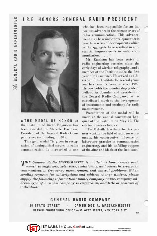
.THE MEDAl OF HONOR of the Ins t itute (If B'l{lio Engineers has heel! a"ardell 10 \lcI"ille Eas lh3111. President of the General Hatlio CompHil)' l' ince it s fou nd ing in 1915.
Thi s gold medal " is given in recognition of (Iis tingui shcd sen ,jcc ill radio conHlHUlication. II is awarded to one
who has been respousible for an illl- ..-porl an l IHlvance in the science or aft of radio COUllllunica tion. Thi s ad,' ancc· men! may be It single developmellt or it llI ay be a series of developmen ts which in the aggrega te ha ve resulted ill sub· stantial improvements in radio com munication ... . "
iHr. Eastham has been active in radio engineerin g societies since the carly days of wireless telegraphy, aud II member of the [nstilu le since the first rear of its existence. He sen 'ed as a di· rec tor of the Institute for several years, lIIui has been its treasurer since 1927. li e now holds tbe membership grade of Fellow. As founder and president of the General Radio Company. he has contributed much to tbe development of instrumen t,s and methods for radio measurements.
Presentation of the medal will be made at the annual convention bau· que t of tbe Institute on May l2. The citation reads as follows:
" To Melvi lle Eastham for his pioneer work in the field of radio measure· ments, his constructive inAueuce on labora tory practice in communicat ion engineering, and bis unfailing support of the aims and ideals of I he rns t i tu te.··
THE Gerlt'ral Radio EX/'EIUMEI"TEIl is mailed u'itllOut clwrge ctlc ll ,no",.11 to c lIg ill cf>rs. scimltists, I.ecll"i,'iuIIs , and ot.l,crs i"teres t.cd i"
COnlmUlli,·uliotl-jrer/U CI/(·Y /II ef/ Sl/re ule I/I. (l"d con/,rol proble",s. IVI' en sendi;,g rer/ueSl s jor sub,;;cripl.ioPls (H,d odclress-clHltI ge not ices. plew.e SIIP!}'Y ,.I'CjOIlOldllg i"jornuttiOl,: II(Urr e, company mIme, comfJ(HlY address. Iype oj uu,'!illess company is c"goge<1 ifl , UTld tille or 110sitioll oj individual.
GENERAL RADIO COMPANY 30 STATE STREET CAMBRIDGE A. MASSACHU SETTS
BRANCH ENGINEERING OFFlCE-90 WEST STREET. NEW YORK CITY
IET LABS, Inc in the GenRad tradition
534 Main Street, Westbury, NY 11590 www.ietlabs.com
TEL: (516) 334-5959 • (800) 899-8438 • FAX: (516) 334-5988
![ru~& Cl ~llli&®©@ Susitna Joint Venture ,, · -- Document Number -· · 2019-04-09 · f_.J.·. ~ ~ fl fll 1J 'il I 1 !}{]£(ru~& Cl ~llli&®©@ Susitna Joint Venture ,, · Document](https://img.pdfslide.us/doc/110x75/5e9954ac0b7e5d52827efb67/ru-cl-llli-susitna-joint-venture-document-number-2019-04-09.jpg)