Embed Size (px)
Citation preview

TECHNICAL BULLETIN NO. 265 OCTOBER, 1931
UNITED STATES DEPARTMENT OF AGRICULTURE WASHINGTON, D. C.
ELECTRICAL EQUIPMENT ON MOVABLE BRIDGES
By CONDE B. MCCULLOUGH, Bridge Engineer, Oregon State Highway Depart-
ment; ALBIN L. GEMEINT, Senior Structural Engvneer, Division of Test», Bu- reau of PuUic Roads; and W. R. WICKERHAM, Electrical Engineer,
CONTENTS
Page Introduction 2 Electric motors 3
Types of electric motors 3 Direct-current motors. -„- 4
Fundamentals of direct-current motor operation __ _ 4
Load characteristics of direct-current motors 4
Speed control of direct-current motors ^ 6 Starting resistance, low voltage re-
lease, overload protection, etc 7 Series-parallel control of motors 8
Alternating-current motors .- 9 Fundamental principles relating to
alternating current_...__ _ 9 Inductance 10 General discussion of polyphase in-
duction motors - 12 Squirrel-cage motors _ 14 Wound-rotor motors... 15 Power factor ___ 16 Speed control of wound-rotor motors. 17 Starting switches, compensators, and
speed controls 17 Single-phase motors 18 Selection of electric motors 18
Direct-current v. alternating-current motors 19
Tests and ratings for motors 19 Special features involved in use of
direct-current motors 20 Special features involved in use of
alternating-current motors . 23 Lubrication 23 Motor housings - 24 Other general features _ 24
Control and interlocking of operations. _ 27 Control and regulation of electric motors _ 28
Starting compensation 28 Speed control and reversal 28 Overload protection 29 Protection against excessive accelera-
tion 30 Control of sequence and interlocking of
operations --. 31 Double-leaf bascule bridges 31 Single-leaf bascule bridges 34 Swing-span bridges .- 35 Vertical-lift bridges 37 General rules for interlocking.
Pilot and indicating devices,..- Protective and travel limit devices Electrical interlocking and control as-
semblies --- Types of electric-control systems
Magnetic contactor details Master switch details _ -._ Resistors Solenoid brakes Limit switches. Motor starting switches Definite time relays--
Page Control and interlocking of operations—Con-
tinued. Miscellaneous and minor control details..
Location of ammeters and voltmeters. Seating of bascule and vertical-lift
spans Wiring Knife switches Grounding connections Telephones, buzzers, and signals Navigation and service lighting Miscellaneous and minor equipment .
Dynamic braking Wiring for electrical control..-
Control system for a double-leaf bascule bridge using alternating current
Wiring for power circuits (stator wmdings) - 68
Rotor windings 71 Auxiliary solenoid brakes 72 Motor-mounted solenoid brakes or
primary brakes 73 Start and stop push buttons 73 Interlock with center-locking mech-
anism Master switches Limit switches-- - Overload relays Current-limit relays Center-lock motor control General remarks .'-
Control system for a rim-bearing swing span, using alternating current-.-
Control wiring Control system for a single-leaf bascule
bridge, using alternating current Incoming lines and service circuits. __ Main control circuit - Roadway gates.-- - _ TraflBc barriers.. Rear jacks Operation of span
Control system for a vertical-Uft span, using direct current
Conclusion Maintenance of interlocking
Recent developments in electrical bridge control:
Variable-voltage control.- Protective and speed-matching indicators
for vertical-lift bridges - Light-sensitive relays 102
Appendix: Definitions - 103 Kinds of protection - - 104 Relays - 104 Qualifying terms of relays 105 Properties and characteristics of appa-
ratus 106 Miscellaneous 106 Rating, performance, and test 106 Manufacturers' specifications 107
61 61
62 62 63 63 63 63 64 64
66
97
64559"—31-

INTRODUCTION
The modern electrified movable bridge involves three elements which are more or less separate and distinct. These are (1) the structural design proper, comprising the moving leaves, the approach spans, and the substructure and foundations; (2) the mechanical assembly, comprising the various gear trains, shafting, and other machinery for transmitting power to the span, and to the various lifts and latching devices, and all other necessary equipment, and (3) the electrical assembly, comprising motors supplying power, and all electrical and mechanical equipment necessary for power regu- lation, speed control and the correct interlocking or sequence of operations.
The structural design of movable bridges is treated in considerable detail in many of the current standard texts on structural analysis. The design of machinery for movable spans has also received con- siderable attention in the engineering literature of the last few years. However, very little data pertinent to the selection of the electrical assembly have been published.
In discussing this question with various bridge engineers, three distinct reactions have been encountered. One group of engineers appears to have dismissed the subject as comparatively unimpor- tant—simply a matter of selection of standard equipment from the manufacturer's catalogue. The second group regards the question as purely the province of the electrical expert, preferring to refer this portion of the design to an outside electrical consultant, specify- ing only basic requirements in their broadest terms. The third group, which is fast coming to represent the majority, feels that the bridge engineer has not given sufficient attention to this phase of design. This group believes that a short publication covering the fundamentals of movable bridge electrification would constitute a valuable addition to the literature on this type of structure.
This bulletin is intended to present in somewhat condensed form a treatment of those fundamental principles which must be applied in making a selection of an assembly of electrical apparatus for bridges.
Consider the nature of the problem—^the highway traffic is com- posed in large part of fast-moving vehicles with all kinds of drivers, many of whom are inclined to neglect the most common safety pre- cautions. This highway traffic is opposed to the water traffic under- neath—a bulky and unwieldy movement with tremendous kinetic energy even at slight speeds, and subject to deviation from its correct path as a result of floods, fog, wind, and cross currents.
Where a movable bridge is necessary these traffic streams should be safeguarded by the installation of a power plant capable of swift and sure acceleration, and a system of control and interlocking which is certain, flexible, and dependable. Many accidents might have been avoided had the power plant met the above specification.
A boat approaching on a freshet stage and at a sufficient speed to avoid losing steerage way—a bridge to be cleared of vehicular traffic before the gates can be closed, an anxious operator watching

ËLECTKICAL EQUIPMENT ON MOVABLE BRIDGEA 3
both traffic ways, timing his operations by split seconds, and then a hoisting motor that will not develop the necessary rapid accelera- tion, or a center lock or wedge motor stalled, or a roadway gate fouled because of faulty interlocking details. This is a situation which is of frequent occurrence.
A majority of the movable bridges in this country use electric power, and bridge engineers have been guided by the manufacturers in the selection of major power units and have placed almost entire dependence upon them in the selection of control and interlocking devices. The large electrical firms have done a great deal to develop control apparatus, and the engineer must be guided by the limita- tions of commercial manufacture. He can not, with due regard for economy, insist upon the production of special equipment except in a few special instances, but he can apply an intelligent understand- ing of fundamental principles, and in the case of wiring and assem- bly, he can produce a specialized arrangement of standard products to fit his particular needs.
Many movable bridges are incorrectly wired. Either the inter- locking is inadequate or the equipment used is lacking in flexibility or is not sufficiently positivé in action, causing uncertainty in opera- tion or high maintenance expense. Much of this trouble may be eliminated by a study of each individual problem, and by the appli- cation of those fundamental principles which form the subject matter to be discussed in this bulletin.
It should be pointed out that this bulletin is not a treatise on in- dustrial power design and control. It does not encroach upon the field of electrical engineering literature and does not go into lengthy discussions or derivations. It is simply a condensed statement of fundamental principles written for the bridge engineer and, for the most part, is based on the personal experience of bridge engineers, and if some of the electrical principles stated appear self-evident or elementary this fact should' be borne in mind.
ELECTRIC MOTORS
TYPES OF ELECTRIC MOTORS
Electric motors are used on movable bridges for thé following pur- poses : For hoisting or swinging the leaves ; for operating end and center wedges or other lifting devices ; for operating locks or latches ; for operating traffic gates and barriers ; and for other auxiliary serv- ice such as the operation of counterweight pit pumps.
In general, motors may be grouped into the following major classes : Shunt-wound direct-current motors, series-wound direct-cur- rent motor, compound, wound direct-current motors, synchronous alternating-current motors, polyphase induction motors (alternating current) of (1) wound rotor type, and (2) squirrel cage type, and single-phase alternating-current motors.
The three types of direct-current motors and the polyphase induc- tion motors are most generally used as power units and will be dis- cussed in the following pages. Single-phase alternating-current motors are sometimes used to operate roadway gates and like equip-

SWITCH-^-,
wwwJ VARIABLE RESISTANCE H
4 TECHNICAL BULLETIlSr 26 5^ TJ. S. DEPT. OF AGRICULTURE
ment but the bridge engineer is not particularly interested in their operating characteristics.
DIRECT-CURRENT MOTORS
FUNDAMENTALS OP DIRECT-CURRENT MOTOR OPERATION
The following brief discussion of fundamentals is presented as a basis for the discussion of control systems.
Figure 1 illustrates the primary elements of a direct-current motor which are a revolving armature consisting of an iron core wound with wires carrying a current, /, and a system of field magnets which pro* duces a magnetic flux, <^, passing through the armature and which is cut by the armature wires when the armature rotates.
When the switch (fig. 1), is closed, the applied voltage, E^ forces a current through the armature winding which produces in it a ten- dency to rotate, since any wire carrying current and lying in a mag- netic field is acted upon by a force tending to move the wire at right
angles to both flux and current. The torque or rotation tendency
is proportional to the product of flux and current or,
Torque=/</> X a constant ( 1 ) The rotation of the armature
wires which move through the mag- netic field induces another electri- cal pressure opposite in direction to the line voltage, E, In other words, the motor in motion acts also as a generator inducing its own volt-
age, E\ The value of this back pressure or counter voltage increases with the speed of the motor.
The difference between the applied voltage and the back voltage at any instant constitutes the effective electrical pressure, which forces the current, / through the armature resistance, R^ that is:
E-E'=RI
From the fundamental law of direct-current generators this back pressure must be proportional both to the speed and to the magnetic field, that is :
ARMATURE
CURRENT,^
FIGURE 1. Primary elements of a direct- current motor
or jE" = r.p.m. X<^Xa constant,
R.p.m.=-r-Xa constant=—7—Xa constant (2)
The above equations serve to explain all of the operating charac- teristics of direct-current motors.
LOAD CHARACTERISTICS OF DIRECT-CURRENT MOTORS
The magnetic flux, </>, is produced by energizing or exciting the field magnets by means of a wire wound about them and carrying

ELECTRICAL EQUIPMENT Oîi^ MOVABLE BRIDGES
current. The flux, <^, is proportional to the exciting current, ¿, and to the number of turns, n^ in the winding. That is :
</>=mXa constant
When the field winding is connected across the line, as shown in Figure 2; the motor is said to be shunt wound. When the field wind- ing is in series with the armature current, as shown in Figure 3, the motor ií5 series wound.
ARMATURE CURRENT,^- ARMATURE
FLUX <t) = [7^^ X A CONSTANT]
FIGURE 2.—Elements of a shunt motor
[ 4) =72. TX A CONSTANT ]
FIGURE 3.—Elements of a series motor
The armature resistance, i?, in any motor is very small, so that the term, Ä/, is always small and the term, E—RI^ is nearly constant. Equations 1 and 2 may be written (for constant line voltage^), as follows:
Torque=/¿X a constant, ^ a constant , . . x K.p.m.= -' (approximate).
In the shunt-wound motor of Figure 2, the exciting current, ¿, is constant with constant line voltage whence, for the shunt motor,
Torque=/X a constant, R.p.m. = a constant (approximate).
For the series motor (fig. 3) i=I^ whence,
Torque=/2Xa constant, ^ a constant , . . ^ K.p.m.= j—— (approximate).
Therefore, for constant line volt- age, the shunt motor is practically a constant-speed motor producing a torque that varies directly as the armature current.
Under like conditions the series motor produces a torque that theo- retically varies as the square of the PLUX 0 = [T^/ X A CONSTANT + TZ'I X A CONSTANT] armature current at a speed that FIGURE 4.—Elements of a compound motor varies inversely as that current.
The compound motor (fig. 4) is a compromise between the above types, obtained by using part shunt and part series windings, and its load characteristics obviously lie between those of the shunt and series-wound types.

6 TECHNICAL BULLÏiTlK 2 6 5, XT. Ö. Î>EPT. OF AGRICULTURE
Typical characteristic curves for the above types of direct-cur- rent motors are given in Figures 5 and 6.
SPEED CONTROL OF DIRECT-CURRENT MOTORS
In movable-bridge operation it is highly desirable that some method be used for controlling and varying the speed of the motors. This is especially true for double-leaf bascule spans where the
ARMATURE CURRENT
FiGUEB 5.—Typical torque-current curves for direct-current motors having the same full-load horsepower and speed rating
HORIZONTAL-^/
^0 ARMATURE CURRENT '■—^
FIGURE 6.—Typical speed-current curves for direct-current motors having the same speed rating at full load
operator will often desire to speed up or retard one of the leaves without resorting to coasting or the application of brakes.
Equation 2 is, r.p.m. ==—-— X a constant, and therefore the
speed of a shunt motor may be varied by varying either E or </>. Eeferring to Figure 7, E=Eo—R'I^ and by varying the resistance R\ the eflPective terminal voltage, E^ is varied and consequently the speed. By varying the resistance, Ä", the field coil current, ¿, is varied, which in turn varies the flux, <;>, proportionately, and the speed inversely.
Resistance inserted in a shunt field winding circuit causes the speed to increase, resistance inserted in the armature winding circuit causes the effective terminal voltage and the speed to decrease. This last method is somewhat wasteful of power.
The speed of a series wound motor may be varied by (1) the use
FIGURE 7.—Speed control of a shunt motor of a Variable resistance in the arma- ture circuit, (2) shunting the field
coils with a resistance, or (3) short circuiting part of the field coils. Pigure 8 illustrates these methods of speed control. In method
A, as the resistance, R\ is increased, the effective terminal voltage, E^ drops, and the speed is reduced proportionately since less back e. m. f. (electromotive force) is now needed. In method B, as the resistance is decreased, the excitation is decreased, and the motor

ELECTBICAL EQUIPMENT ON MOVABLE BRIDGES
speeds up. In method C, as more of the field coils are cut out the flux, (f}^ is decreased and the motor speeds up.
Compound motors are sometimes controlled by short circuiting the series windings after the motor has attained a certain speed, thus converting it into a simple shunt motor. The series character- istics are advantageous for starting while the shunt characteristics are advantageous for speed regulation after starting. This type of control is sometimes used for electric elevators, but is rarely used for bridge control.
The methods by which the resistances are varied and controlled are discussed on subsequent pages.
STARTING RESISTANCE, LOW-VOLTAGE RE- LEASE, OVERLOAD PROTECTION, ETC.
Eeferring to Figure 1, if the switch is closed with all the starting resistance cut out, a large current will flow through the armature, since the back pressure at the in- stant of starting is zero. This excessive current will quickly burn out the armature windings. To prevent this action, a variable start- ing resistance is used. The cir- cuit is closed with all resistance in, ^ and a small current flows through VA'RIABLE REsisfANCE ,1 . • T Tj?ji j IN PARALLEL WITH COIU the armature wmdmg. It the torque -i produced by this current is not sufficient to turn the motor, resist- ance is gradually cut out until the current is sufficient to furnish the required starting torque. As the motor speeds up the resistance is gradually cut out to balance the increasing back pressure. At full- load speed the resistance is gener- ally all cut out, and the armature is carrying full-load current. If the load on the motor is increased, it slows down slightly if it is a shunt motor and considerably if it is a series motor. This loss in speed decreases the back pressure and allows more current to flow.
Such a starting arrangement requires safeguarding against two dangers as follows :
(1) If the power should go off with the resistance all cut out and then come back on, the full current may burn the armature winding provided the operator has not opened the line switch or thrown in the resistance. As a safeguard, a low-voltage release is provided to automatically clit in the full resistance, or else open the circuit, when the line voltage drops below a certain predetermined value.
(2) An excessive load demand during operation may draw a destructively high current through the armature. This contingency is provided for by means of a circuit breaker or overload relay, or by means of fuses.
SWITCH FOR SHORT CIRCUITING r^ PART OF^\/ FIELD Y COILS ^^ /*:
«^
FIGURE 8.—^Three methods of speed con- trol for a series motor

8 TECHNICAL, BULLETIN 2 6 5, U. S. DEPT. OP AGRICULTURE
'//////y////////y>/y////////////A "%
\^:^Tny
Figure 9 is a'diagram of a hand-operated motor starter fitted with overload protection, and low-voltage release. A current passes through the metal contact arm. A, and through the variable resist- ance to the armature as shown. The normal position of this arm is such as to keep the motor circuit open, the arm being held in the open position by means of a spring. To start the motor, the arm is moved around the resistance arc and, step by step, the resistance is cut out. At the last step the magnet, M, attracts and holds the arm in the full-load position. The magnet winding is shunted across the main line as shown.
If the power suddenly goes off, or if the line voltage drops suffi- ciently, the force of the magnet is overcome by the spring and the arm springs back, opening the circuit. T^iis device is termed a
" low-voltage release mechanism." The main armature current passes
through a solenoid, and at a certain predetermined overload current value the solenoid core is lifted so as to close the contacts C-C^ This short circuits the magnet, and again the arm springs back to its open position. This is an overload release.
This is one of many methods of control and is simplv illustrative of a principle. The subject of start- ing resistances, overload relays, circuit breakers, controllers, and master switches is too large to present here, and data is available
FIGURE 9.—Hand-operated motor starter m manufacturers' Catalogues Or ^eiäse^^""^*^^^ protection and low-voltage standard tcxts. Further discussion
of control will be found in the sec- tions which treat of control equipment.
SERIES-PARALLEL CONTROL OF MOTORS
Figure 10 illustrates a method of connecting series motors in pairs which has sometimes been used for the operation of movable spans. The first section of the controller connects the motors in series with each other. As the controller handle is moved around, successive resistance steps are cut out, and at the end of the first section the starting resistance is all cut out and the motors are operating in series, each motor operating on one-half the line voltage. The next step on the controller changes the terminal connections, throwing the motors in parallel and cut in all the original resistance. This resistance is again cut out step by step until the motors are each operating under the full line voltage.
With the motors in series, each motor takes the full line current at half the line voltage. A strong torque at a low speed is produced without drawing excessive current from the line. In the parallel connection each motor takes half the line current at the full line yoltage and produces less torque but operates at a higher speed,

ELECTRICAL EQUIPMENT ON MOVABLE BBIDGES
ALTERNATING-CURRENT MOTORS
FUNDAMENTAL PRINCIPLES RELATING TO ALTERNATING CURRENT
Alternating current is generated whenever a revolving magnetic field of alternating polarity cuts one or more stationary conductors, as shown in Figure 11, A. The current (and the electromotive force) reverses in direction once during the time required for any two adjacent poles to pass a conductor.
-fOC STATIONARY^ ></
WIRES '^ '
360 ELECTRICAL DEGREES
NOTE- CLOSE SWITCH S, AND OPEN SWITCH S2
TO TRANSFORM TO PARALLEL CONNECTIONS AS SHOWN BELOW
SWITCH S2
FIGURE 10. — Series-parallel diagram
control FIGURE 11.—Diagram to illustrate prin-
ciple Involved in an alternating-current motor
The.e. m. f. and the current vary as shown graphically in Figure 11, B. The distance, OP, represents a complete cycle or 360 electrical degrees.
The frequency of the e. m. f. is the number of cycles per second, and is represented, hereinafter by the symbol, /.
If f be the number of poles, obviously
^_r p.m. p_r.p.m.Xp 60 120
An e. m. f. imposed upon a single circuit is known as a single- phase voltage, or e. m. f. Suppose there are three such circuits, the e. m. f. in each circuit lagging the adjacent e. m. f. by 120 elec- trical degrees. The graph of the three voltages superimposed would be as shown in Figure 11, C. Such a voltage is known as a polyphase voltage (in this case, a 3-phase voltage) and the resulting current is termed a polyphase current.

10 TECHNICAL BULLETIN 26 5^ XT. S. DEPT. OF AGElCtTLTTJEE
Suppose there are three alternating-current generators (or more exactly, three independent coils on one generator), each generating an alternating current, and so arranged as to lag each other by 120 electrical degrees. Instead of the six wires shown in Figure 12, A, suppose that wires &, d^ and e were connected together to form a
common lead, as shown in Figure 12, B. This common lead wire car- ries the three currents formerly carried by wires &, d^ and ^, but from Figure 11, C it is readily seen that the algebraic sum of the three voltages at any instant is zero. Since there is no voltage there can be no current and the wire can be dispensed with as shown in Fig- ure 13, A. This method of con- necting the lead wires from the three stator coils of a 3-phase gen- erator makes it possible to carry a 3-phase current over three wires, each wire acting as a return for the other two.
Y CONNECTION
A
i^-n
FIGURE 12.—Diagram illustrating princi- ples involved in generating 3-phase current
Two methods of connection are used, the one in Figure 13, A being known as the Y connection and the one shown as Figure 13, B being termed the A (delta) connection.
If each phase coil generates a volt- age, E^ across its terminals, and a current, /, the currents and voltages in and across the line wires, for the two different methods of connection are as shown in Figure 13. A proof of this fact will be found in any textbook on alternating current.
Figure 14 shows the different ways in which loads are connected to a 3-phase main.
A CONNECTION
B FiGUKE 13.—Methods of connecting wind-
ings of a 3-phase generator
INDUCTANCE
Whenever there is a change in the current flowing in any line, there is induced an e. m. f. opposite in direction to the current change. This electromotive force is known as the e. m. f. of self-

ELECTRICAL EQUIPMENT ON MOVABLE BRIDGES 11
induction. Without going into a theoretical and lengthy discussion, the following facts may be stated.
The e. m. f. of self-induction is proportional to the rate of change in the current. It is zero at the instant that the current ceases to change, and a maximum when the current is changing the most rapidly.
This e. m. f. is always in such direction as to oppose the change in current. When the current is increasing, the induced e. m. f. tends to cause the current to decrease, and vice versa. The greater the frequency of an alternating current, the greater the e. m. f. of self-induction.
Consider the alternating current shown graphically in Figure 15. At the instants a^ &, and c^ the cur- rent change is zero. Therefore, the e. m. f. of self-induction is zero at these points. Between a and &, the current is decreasing, therefore, the e. m. f. of self-induction must be positive between these points. Be- tween h and c, the current is in- creasing, therefore, e. m. f. of self- induction must be negative. The maximum rate of change in current takes place at the instants d^ e^ and /, which indicates that these points must be the points of maximum e. m. f. of self-induction. Plotting the e. m. f. curve through these control points results in the dotted curve of Figure 15 which must be the curve of Ei^ the e. m. f. of self- induction.
The impressed voltage, E^ must be sufficient to overcome this coun- ter voltage, Ei^ and also to force the current, /, through the resist- ance, R, of the circuit.
If this resistance is zero, then the impressed e. m. f. is only just equal and opposite to the e. m. f. of self- induction, and varies as shown in ^^^^^'^^^ ^^-^^lÄe curîeSt^^'""^ ^""^^^ Figure 15.
The above facts are the basis of the following very important law : In inductive circuits of negligible resistance, the applied voltage leads the current by 90 electrical degrees, or, as generally expressed, the current lags the voltage by 90 electrical degrees.
The self-induction of a circuit acts against the impressed or ap- plied voltage, and lessens its power to force current through the line. The value of this resistance is generally termed the " inductive re- actance," and is expressed in ohms.
If, in any circuit there be a resistance, A, and also an inductive re- actance, X, the impressed voltage no longer leads the current by 90 electrical degrees, but by some angle, 0^ which may be determined from the following considerations.
THREE LOADS A CONNECTEQ

12 TECHNICAL BULLETIN 2 6 5^ U. S. DEPT. OF AGRICULTURE
rE- e.mf. OF SELF-INDUCTION
/'\ .^. '^-
B'iGURE 15.- between current, impressed voltage, and e. m. f. of self-induction
The impressed voltage, E (fig. 16), must have a component, E\ equal to RI^ and in phase with the current, /, else it could not over- come the resistance R. This voltage must also have another compo- nent, E'\ equal to IX^ and in phase with it, else it could not overcome the inductive reactance, X, This inductive reactance leads the cur- rent, /, by 90°, as shown above. Therefore, these two components
are at right angles, and the result- ant voltage is found as shown in Figure 16.
The actual useful power in the circuit is measured by the product of the current, /, times the voltage component, E\ in phase with /, since the other component (in phase with X) is balanced by the e. m. f.
-Diagram showing relation of self-induction. That is, power in watts=E'I=
El cos e. The term, cos 9, is called the power factor, and varies with the
ratio of inductance, X, to resistance R.
GENERAL DISCUSSION OF POLYPHASE INDUCTION MOTORS
The essential parts of a polyphase induction motor consist of a stator or stationary element with windings carrying the several phases of the line current, and a rotor inside the stator. If the rotor wires are connected together at their extremities, the motor is known as the squirrel-cage type. If they terminate in brushes, which are connected with variable resist- ance elements, it is termed the wound rotor^ or slip-ring type of motor.
Figure 17 shows a stator of an induction motor wound for a 3- phase current with the phases spaced 120 electrical degrees around the ring. When the cur- rent in phase 1 is a maximum posi- tive value, the value of the current in both phase 2 and 3 is equal to -/sin 30°-1/2/.
The resultant magnetic field is therefore in the direction shown in Figure 17 at this instant. When the current has passed through 120
electrical degrees (after ^ sec-
onda, where /is^hè frequency) the value otpKa^e 2 is maximum and positive, an^d that of both phase 3 and phase 1 negative and each equal to orie-half the maximum value. The resultant magnetic field at this instant is, therefore, 120° to the left of its original position. After another equal interval the field is 240° to the left of its original
-js^'je^-
^RESI STANCE^
—/VWWWV\A
-JS'-J^J^-
j_NDUCTIVE REACTANCE,
-mmmm^
FIGURE 16.—Determination of resultant voltage in an alternating-current cir- cuit containing resistance and reactance

EL.ECTEIGAL. EQUIPMENT ON MOVABLE BEIDGES 13
position. A 3-phase current, therefore, produces a rotating magnetic field with a speed in r. p. m. of 60/ for a 2-pole machine. For multi- polar machines with P poles, the speed of the revolving magnetic n 1-, . 60/* 120/ field IS, r. p. m.= T7-p = —p^-
This is known as synchronous speed, and depends on the frequency of the applied current, and not on the motor load. The action of the rotating magnetic field is exactly the same as if the permanent magnets of Figure 18 were revolved about the rotor at synchronous speed.
Suppose the rotor of Figure 18, A to be at rest and current sud- denly applied to the stator winding. The hypothetical magnets, N
HOVEMENT OF MAGNETIC FIELD
DIRECTION OF MAGNETIC FIELD WHEN EACH PHASEISA MAXIMUM
FIGURE 17.—Diagram illustrating principles involved in an induction motor
and S, start to revolve at synchronous speed, and an electromotive force is induced in the rotor wires. This e. m. f. induces a current in the rotor wires and since these wires already lie in a magnetic field, a torque is at once developed which tends to revolve the rotor, and with it the motor shaft. The flux is moving downward with respect to the wires on one side of the line A-A (fig. 18, A), and upward with respect to the wires on the other side of this line. The induced e. m. f., therefore, is opposite in direction on the two sides of the line A-A.
If the rotor current is in phase with the rotor voltage, the condi- tion shown in Figure 18, A obtains (i. e., relative motion and cur- rent reverse at the same time), and the torque is all in one direc- tion.. If, on the other hand, the induced rotor current lags the volt-

14 TECHNICAL BULLETIN^ 2 6 5^ U. S. DEPT. OF AGRICULTURE
age, a condition such as shown in Figure 18, B obtains, and part of the torque is negative. From Figure 18, B the retarding torque sector is seen to be proportional to the current lag, 9.
SQUIRREL-CAGE MOTORS
The above fundamentals will now be applied in a discussion of the load characteristics of polyphase motors. Assume the motor at rest and no stator current flowing. At the instant the line switch is closed, the magnetic field induced by the phase winding starts to revolve at synchronous speed, and currents are set up in the rotor
MOTION OF MAGNETIC FIELD
ACCELERATING SECTOR
C D FiGüHB 18.—^Diagram illustrating principles involved in induction motors
bars. The frequency of the rotor currents at the instant of start- ing must be the same as that of the stator currents, since the rotor has not started to move. With this relatively high frequency, a large inductive reactance is introduced (since the inductance varies as the frequency). Since the rotor resistance must always be rela- tively low (to avoid excessive heating), the current must, in this case, lag the induced e. m. f. by a large angle. A large retarding torque sector (fig. 18, C) is, therefore, developed so that the net or useful torque is relatively small while the rotor current, /r, is quite high. At starting, therefore, there is a relatively small starting torque, with a relatively high starting current. Generally, a starting current

ËLECTEICAL EQUIPMENT OK MOVABLE BRIDGES 15
2qual to about five times the full-load current is needed to develop 150 per cent of full-load torque.
As the torque develops sufficiently to overcome the inertia of the rotor and the external load, the rotor starts to rotate. For no load conditions, the rotor accelerates to practically synchronous speed ; for full load, the rotor generally has a slip of about 4 per cent ; i. e., the rotor moves through 96 per cent of one revolution, while the stator field makes a complete circle.
As the frequency of the rotor current depends upon the rate at which the rotor bars slip past the rotating field, the full-load fre- quency is but 4 per cent of the frequency at starting. This low frequency reduces the reactance in the rotor circuit proportionately and, therefore, reduces the current lag since the rotor resistance is constant, and the rotor currents become more nearly in phase with the rotor voltage. Full-load torque is, therefore, developed at a greatly increased power factor. Full-load torque at full-load speed obviously requires the rated full-load current, while for this same torque at the start about 330 per cent of the full-load current is required.
As the load on the motor is increased above the rated full load the rotor slows down and the percentage of slip becomes greater. This increase in slip increases the amount of current in the rotor bars and also increases the frequency. The current increase tends to increase the torque, while the increased frequency increases the current lag and, therefore, decreases the torque. Up to a certain load the cur- rent increase is greater in its effect than that of the frequency in- crease and, therefore, the torque increases to carry the increased load. Above a certain point, however, the effect of the lag in rotor currents is more than the effect of the increased current itself. At this point the motor starts to slow down, and the torque decreases with any further increase in current. (Fig. 22.)
The change in current values is great even for a small change in the percentage of slip, so that the squirrel-cage motor is to all intents and purposes a constant-speed motor. This type of motor always takes a lagging current, and has a power factor at full load varying between 80 and 90 per cent, depending on the size.
The synchronous speed of a squirrel-cage motor may be found by the formula
120/ r. p. m. =—p—
Full-load speed is generally about 96 per cent of synchronous speed. The large current required by the squirrel-cage motor for starting
under full load is the principal objection to this type and eliminates it from consideration for heavy starting duty. It is, however, very sturdy in construction, and has no brushes or sliding contacts such as the commutator of a direct-current motor or the slip rings of a wound-rotor motor. For small units or other use not involving heavy starting duty this motor is very satisfactory.
WOUND-ROTOR MOTORS
It has been pointed out that for the squirrel-cage motor the large ratio of current to torque at starting is due to the lagging current, which in turn is a function of the high reactance and low resistance

16 TECHKICAL BULLETIN 2 6 5, V. S. DEPT. OF AGRICULTURE
of the rotor. For example, if the resistance R in the rotor circuit (fig. 19) be.increased to B% then the angle of current lag decreases from 0 to O', and the retarding sector on the rotor is decreased proportionately. (Fig. 18, C, D.) By increasing the rotor re- sistance a larger torque is produced with less current, and the angle of lag can be so reduced that full-load torque at starting may be developed at about full-load current.
As soon as the rotor speeds up the resistance is no longer needed, since the reduced frequency of the rotor current automatically takes care of the current lag, and this high rotor resistance would cause heavy power loss due to heating. Instead of having the rotor bars connected together at their extremities, the wound-rotor motor terminates these bars on slip rings to which are wired resistance grids arranged so that
FiGUBB 19.—Diagram showing effect of theV maV be CUt OUt step bv Stcp aS introducing resistance in rotor of indue- j.i .*^ j FTM-J.^ tion motor the motor speeds up. This type of
motor is suitable for heavy starting duty, as it has much better starting characteristics than the squirrel- cage type.
For the main hoisting or turning motors of a movable bridge the wound-rotor or slip-ring type should preferably be used if the power required is in excess of 15 to 18 horsepower. Below this value squir- rel-cage motors can be used. They are also suitable for such pur- poses as the operation of pumps, locks, latches, gates, and barriers. Squirrel-cage motors having what is known as " high-resistance rotors " are sometimes used for in- termittent duty of this kind and may be used for power units up to 25 horsepower and perhaps even higher.
STATOR VOLTAGE
MAGNETIZING CURRENT
FIGURE 20.—Effect of load current on power factor
POWER FACTOR
Thus far the discussion has been of rotor currents, voltages, and re- sistances. The stator current, how- ever, is the metered current for which the consumer pays. Under no load, the stator currents lag the voltage by nearly 90°, as the resistance of the stator windings is low and the only impedence is the reactance of the circuit.
As the load comes on the rotor develops a slip, and rotor currents are developed which tend to demagnetize the stator. To counteract this tendency a load current is developed in the stator which must be in phase with the stator voltage.
As the load current increases the power factor increases, as shown in Figure 20. For example, if Oa represents the value of the stator load current at one-half full load, the power factor is cos 9. As the load is increased to full load, the magnetizing current or current

ELECTRICAL EQtJlPMEKT OK MOVABLE BRIDGES 17
opposing the inductance remains practically constant, the load cur- rent increases to the value Ö&, and the power factor becomes cos 0'.
The power factor for an induction motor varies with the load approximately as follows :
Power factor, per cent
8 55 72 80 87 90
SYNCHR0r40US SPEED
100 leo 200 250 300 350 400 TORQUE (FOOTPOUNDS)
FIGURE 21,—Torque-speed curves for slip-ring induction motor
1000
Percentage of full load
0 25 50 75
100 150
It is not advisable to design a power system so that the motors are always underloaded, as this means not only a waste in the first cost but also a low power factor and a consequent plant waste at the point of generation,
SPEED CONTROL OF WOUND-ROTOR MOTORS
The motor torque depends upon the rotor current which in turn is induced by the slip of the rotor. If, at any given load and speed resistance were inserted in the rotor circuit, the rotor current would drop and the torque would de- crease. This would cause the rotor to slow down until the additional slip produced the required torque current. The motor would then continue to rotate and carry the load, but at a reduced speed. Speed control on wound-rotor motors is therefore made possible by varying the resistance in the rotor circuit.
Figure 21 shows the torque-speed curves for a 440-volt, 60-cycle, 6-pole, wound-rotor, induction mo- tor having five resistance steps. These curves are self-explanatory. between speed, torque, and current for a 440-volt alternating current motor.
STARTING SWITCHES, COMPENSATORS, AND SPEED CONTROLS
The full line voltage can be thrown directly on the stator of small, sq[uirrel-cage motors by means of an ordinary knife switch, but all circuits should be protected against overload by suitable fuses. In starting large motors, use is frequently made of autotransformers, or starting compensators, which are placed in the line to reduce the voltage at starting and thus avoid the possibility of dangerously high currents.
64559°—31 2
0 10 20 30 40 50 60 70, 80 90 100 SPEED AS A PERCENTAGE OF SYNCHRONOUS SPEED
FIGURE 22.—^Tjrpical speed-torque and speed-current curves for a 440-volt al- ternating current motor rated at 1,200 r. p. m.
Figure 22 shows the relation

18 TECHKICAL BULLETIÎiT 26 5, TJ. S. DEPT. Oí^ AGRICTJLTUKE
The Y-delta method of starting is sometimes used. This method depends for its action on the difference in voltage across Y-connected against delta-connected loads as shown in Figure 14. During the starting period the stator windings are Y-connected to the line, giv-
ing a voltage of rö-or 58 per cent of the line voltage. As the
machine speeds up, the connections are thrown into a delta connec- tion, increasing the voltage to E or 100 per cent of the line voltage.
These starting devices are used for squirrel-cage motors, while the slip-ring motors need no device other than the variable rotor resis- tance. This latter type of control, which is most readily effected with magnetic contactors (remote or magnet control), presents so many advantages that its use for movable-bridge operation is becom- ing almost universal. This method of control and also the question of motor starters in general is to be discussed more fully in following pages.
SINGLE-PHASE MOTORS
It is sometimes necessary to use single-phase motors for small units because no other current is available. For units above a single horsepower this should not be done unless unavoidable, as 3-phase motors are always considerably less expensive, less complicated as to wiring, and easier to install and maintain.
As an illustration, the following quotations on 2-horsepower and 3-horsepower units have recently been made for use on a bridge.
2-HORSEPOWER GATE MOTORS
Single-phase (reversible) $75 Three-phase 43
Difference 32
3-HORSEPOWER BARRIER MOTORS
Single-phase (reversible) $94 Three-phase i 48
Difference •_ 46
There is also the factor that single-phase motors must be fitted with brushes which are always likely to cause some trouble or expense because of sparking or flashing over.
SELECTION OF ELECTRIC MOTORS
The determination of the power required for movable bridges is so thoroughly covered in current literature that it need not be re- peated here. The discussion which follows is, therefore, based on the assumption that the torque and power demands at the motor shaft for all conditions of loading, have already been determined.
The fundamental principles underlying the operation of electric motors have been discussed and it now remains to summarize this subject matter and deduce a few simple rules for the guidance of the engineer in specifying and selecting equipment.

ELECTRICAL. EQUIPMENT OlüT MOVABLE BRIDGES 19
DIRECT-CURRENT VERSUS ALTERNATING-CURRENT MOTORS
The choice between direct-current and alternating-current motors will, of course, be largely controlled by the character of electrical energy commercially available. Alternating current is used for general distribution through high-voltage lines because of its flexi- bility. The majority of commercial service lines carry alternating current, while direct current is used for street railways and for dis- tribution in industrial centers. The majority of installations for movable bridges make use of alternating current because of its more frequent commercial use. Where both types of current are available at approximately equal rates, the choice between the two is largely a matter of personal preference.
The direct-current series motor has starting characteristics some- what better adapted to heavy hoisting duty than the polyphase in- duction motor as indicated by Table 3. Direct-current motors are apt to have more sparking at the brushes than wound-rotor motors, especially where commutating poles have not been supplied. Ma- chines of the squirrel-cage type do not have such trouble.
Alternating current is more flexible, easier to handle, and some- what easier on contacts because the frequent current alternations minimize the tendency to spark.
All things considered, alternating current is perhaps slightly more desirable tSan direct current for movable bridges.
TESTS AND RATINGS FOR MOTORS
The capacity of any motor is limited by two factoi's—commuta- tion and temperature rise. Commutation is necessary only on direct- current motors and certain types of single-phase machines, and if commutating poles are supplied the sparking at the brushes is greatly minimized.
The horsepower of a motor is a function of torque and speed which are in turn functions of the voltage and load current. The load current is limited to that value which will not heat the motor to a point detrimental to the insulation. It is apparent that the internal temperature of the windings is a function of the time during which the motor operates so that the size or capacity of any motor is not a fixed term but a term which has a variable meaning, depending upon the period over which it must be operated continuously. This is illustrated by Table 1 taken from the catalogue of a manufacturer.
TABLE 1.—Horsepower rating of direct-cwtrent motors for different periods of time hased on a limiting rise in temperature of 75° C.
Motor One-fourth hour
One-half hour Ihour 5 hours
A - - Horsepower
m 33 80
180 300
Horsepower m
28 65
140 250
Horsepower 6
20 50
100 185
Horsepower
B - . ... 14 C 30 D 62 E 100
20 TECHNICAL, BULLETIIsT 2 6 5, U. S. DEPT. OF AGRICULTURE
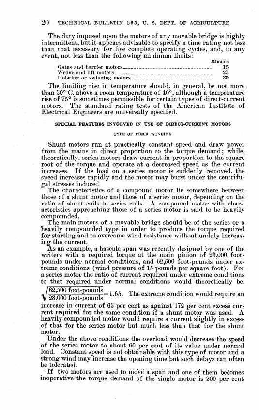
The duty imposed upon the motors of any movable bridge is highly intermittent, but it appears advisable to specify a time rating not less than that necessary for five complete operating cycles, and, in any event, not less than the following minimum limits :
Minutes Gates and barrier motors 15 Wedge and Uft motors 25 Hoisting or swinging motors 80
The limiting rise in temperature should, in general, be not more than 50° C. above a room temperature of 40°, although a temperature rise of 75° is sometimes permissible for certain types of direct-current motors. The standard rating tests of the American Institute of Electrical Engineers are universally specified.
SPECIAL FEATURES INVOLVED IN USE OF DIRECT-CURRENT MOTORS
TYPE or FIELD WINDING
Shunt motors run at practically constant speed and draw power from the mains in direct proportion to the torque demand; while, theoretically, series motors draw current in proportion to the square root of the torque and operate at a decreased speed as the current increases. If the load on a series motor is suddenly removed, the speed increases rapidly and the motor may burst under the centrifu- gal stresses induced.
The characteristics of a compound motor lie somewhere between those of a shunt motor and those of a series motor, depending on the ratio of shunt coils to series coils. A compound motor with char- acteristics approaching those of a series motor is said to be heavily compounded.
The main motors of a movable bridge should be of the series or a lieavily compounded type in order to produce the torque required for starting and to overcome wind resistance without unduly increas- ing the current.
As an example, a bascule span was recently designed by one of the writers with a required torque at the main pinion of 23,000 foot- pounds under normal conditions, and 62,500 foot-pounds under ex- treme conditions (wind pressure of 15 pounds per square foot). For a series motor the ratio of current required under extreme conditions to that required under normal conditions would theoretically be.
62,500 foot-pounds -, ¿.¡r mu ^ j-x- u oo Ann -c—± T- = 1-65. i he extreme condition would require an 23,000 foot-pounds ^
increase in current of 65 per cent as against 172 per cent exqess cur- rent required for the same condition if a shunt motor was used. A heavily compounded motor would require a current slightly in exc^s of that for the series motor but much less than that for the shunt motor.
Under the above conditions the overload would decrease the speed of the series motor to about 60 per cent of its value under normal load. Constant speed is not obtainable with this type of motor and a strong wind may increase the opening time but such delays can often be tolerated.
If two motors are used to move a span and one of them becomes inoperative the torque demand of the single motor is 200 per cent
V

ELECTRICAL EQUIPMENT ON MOVABLE BRIDGES 21
of normal. This will double the current passing through a shunt motor, but will increase the current in a series motor by only about 41 per cent. Current induced by overloading causes a tempera- ture rise in the motor, and the maximum load is limited by the maximum current which may be induced without heating to a tem- perature destructive to the insulation. The safe load on a direct- current motor, as has been stated, is often limited by commutation (unless interpoles are used), as an excessive armature current weak- ens the reversing field, and causes destructive sparking at the brushes. If a shunt motor is used a larger power unit should be employed as less margin can be allowed for overload.
A series motor is not suitable to operate pumps for the counter- weight pit of a bascule span, since the suction pipe might break and release the load and let the motor attain a dangerously high speed.
For roadway gates and traffic barriers, either shunt motors or com- pound motors with pronounced shunt characteristics are preferred in order to have constant speed, since no great amount of overload is likely to be applied. Where chain drives are used to operate gates there is a possibility of chains breaking and removing the loaa and the shunt characteristics are best suited for this condition.
Center locks for double-leaf bascule spans and center wedges or lifts for swing bridges may be operated by shunt motors or those having a light compounding. End wedges for swing spans, how- ever, should preferably be driven by a heavily compounded motor in order to develop the necessary power at the end of the lift when wedge friction is a maximum or when a wedge is jammed. Shunt motors have been used for such service in many instances, but the experience of the writers with end-wedge lifts indicates that a motor with better overload characteristics is desirable.
In general, the main hoisting motors or turning motors, end- wedge motors and those for any other duty demanding occasional overloading should possess strong series characteristics unless the conditions are such as to make possible a sudden release of load. Motors for lighter duty or where constant speed is desirable, may be of the shunt type or the compound type with shunt characteristics.
COMMUTATION
The following brief discussion is presented to explain the value of commutating poles on direct-current motors for certain kinds of service.
Figure 23, A shows part of the armature and commutator of a common type of direct-current generator. Each of the armature coils revolving through the inain magnetic field carries a current. These coils are in series so that the current induced in each coil flows through every other coil between it and the commutator segment in contact at that particular instant with the brush. An instant before the armature assume the position shown in Figure 23, commutator segment C was back of its present position so that point d was at some point d' over the brush. Thus the commutator segments B and C were connected and coil A was short circuited. As com- mutator segment C moves on past the brush, coil A is suddenly:, thrown in series with coil E. This sudden change of current in.fcoil A is opposed by the self-induction of the coil as indicated by^tiie-

22 TECHNICAL, BULLETIN 2 6 5, U. S. DEPT. OF AGRICULTURE
arrow; thus causing a part of the current to be forced across the gap and into the brush, causing sparking.
If the brush is shifted forward to the position shown by the dotted outline, coil A would still be short-circuited during a certain period of the rotation, but it would be short-circuited in a reversing mag- netic field since it has now been moved under the pole tip N.
This discussion can be applied to a motor where the armature current is applied rather than induced if it is remembered that the direction of rotation is reversed. The following general rule may be stated: To avoid sparking, the brushes must be shifted forward for generators and back for motors.
C0MMUTATIN6 POLE PIECE •COMMUTATING FIELD LINES
VVVVVS^VVV^^V-VSVVVVWWVV v////////^y/^/////^y//////
ARMATURE REACTION RESULTANT FIELD (OUETO ARMATURE REACTION
AND FIELD MAGNETS)
FIGURE 23.-
WEAKENED FIELD
-Diagram illustrating cause and metUod of control of commutating diflaculties
Figure 23, B indicates the distribution of flux through the arma- ture of a generator or motor due to the field magnets only. Figure 23, C illustrates the magnetic field produced by the armature wind- ing. Figure 23, D shows the resultant of these two fields. It is apparent that the effect of armature reaction is to weaken the re- versing field, and that furthermore the degree of weakening is di- rectly proportional to the armature current. For sparkless com- mutation, therefore, it would not only be necessary to shift the brushes further on account of armature reaction, but the neutral position for these brushes would vary with the load (the armature current).
To avoid this difficulty, interpoles or commutating poles may be placed as indicated ia Figure 23, A. The function of these poles

ELîECTRICAL EQUIPMENT ON MOVABLE BRIDGES 23
is to create an auxiliary reversing field for the armature coil which is being short circuited.
The following statement on commutating poles is quoted from the catalogue of a large electrical manufacturing company.
OVERLOAD CAPACITY AT COMMUTATOR IS OBTAINED BY THE USE OF COMMUTATING POLES
The weakest point of a noncommutating-pole motor is the commutator, on account of its tendency to disintegrate because of the sparking and wear by brush friction. The commutating pole motor is primarily a non-sparking ma- chine with the result that a much lighter brush tension may be used. In fact, no other feature adds so much to the durability and overload capacity of a direct-current motor as the use of commutating poles. The beneficial efíects of commutating poles are particularly noticeable on the higher voltages, and en circuits having a wide and rapidly fluctuating voltage where they greatly minimize the tendency to flash over at the commutator.
The neutral point of commutating pole machines Is fixed, regardless of the direction of rotation, therefore commutation poles are particularly valuable on reversible motors.
The commutating pole windings are in series with the windings of the arma- ture and main poles. This makes the advantages of the commutating poles markedly effective in the case of series-wound motors, for as the load in- creases, the excitation of both the commutating and main poles increase equally and together, resulting in an enormously increased capacity of the machine to stand sudden heavy overloads without sparking at the commutator.
SPECIAL FEATURES INVOLVED IN THE USE OF ALTERNATING-CURRENT MOTORS
For the main hoisting or swinging motors the following general practice should guide the selection :
For power units of less than 15 horsepower : Squirrel-cage motors may be used, although slip-ring induction motors are somewhat pre- ferred on account of the need for some speed control.
For power units between 15 and 25 horsepower : Either slip-ring induction motors or squirrel-cage motors with high-resistance roto*' should be used. Again the slip-ring type is preferred.
For power units above 25 horsepower: The slip-ring induction motor should be used and care taken to provide enough resistance steps to accelerate and decelerate the span throughout its complete operating cycle at such a rate as to completely eliminate all shock and jar, and to provide a speed range sufficient for the needs of the installation.
For center locks, tail locks, end wedges and lifts, pit pumps, road- way gates, and all other light duty, ordinary squirrel-cage motors are satisfactory.
LUBRICATION
The method of lubrication will depend upon the nature of the in- stallation. Swing bridges and vertical-lift spans have stationary motors. This is also true of the main hoisting motors in certain types of bascule bridges. For certain types of rolling-lift spans, however, and for motors which operate center-locking mechanisms or tail locks, the motors must rotate with the moving leaf. Motors which are mounted on a stationary portion of the structure may be lubri- cated by means of oil rings. Motors which rotate with the moving leaf, however, must be equipped for oil waste or wick lubrication or

24 TECHNICAL BULLETIK 26 5^ U. S. DEPT. OF AGRICIJLTUBE
fitted with grease cups or other effective system for pressure lubri- cation.
MOTOR HOUSINGS
The housings of motors are generally classified as open frame, semiinclosed (perforated covering), and totallv inclosed. The open- frame motor has better ventilation, and, therefore, heats less rapidly under heavy current. Since the capacity of any motor is entirely a matter of temperature rise (unless commutation is a factor), a smaller power unit may be selected if an open-frame design is per- missible. For open air service, however, open-frame construction may result in damage to the armature and windings due to moisture, dirt, dust, and other conditions of exposure. All motors except those which are located in completely inclosed, heated rooms should prefer- ably be of the inclosed type.
Certain conditions may preclude the use of open motors and yet not necessitate a full inclosure. For such a condition, perforated covers (the semiinclosed type) may be used.
Under severe conditions motors may be fitted with a complete inclosure having an air intake and an air outlet for the connection of ventilation pipes. Motors thus equipped are commercially avail- able and are of two types ; those arranged for external ventilation, and the self-ventilated type which is equipped with fans as an integral part of the machine.
OTHER GENERAL FEATURES
In general, the motors on any bridge should be arranged and located so as to permit of the most efficient system of ventilation and to permit easy access to all parts for inspection and repairs.
Where both 2-phase and 3-phasè alternating current is available, preference should be given to the 3-phase current because of the better distribution of the stator windings which increases the effi- ciency of the motor. The power factor is also higher and the start- ing characteristics better with the 3-phase motor. There is also a saving in the amount of copper required for the distribution system.
For the same power rating, high-speed motors weigh less, occupy less space, and cost less than low-speed motors. Table 2 illustrates the variation in weight for a few typical alternating current induc- tion motors of various speed ratings.
TABUE 2.—Weight and speed of typical SO-cycle altematinff-owrrent induction motors
30 horsepower 50 horseix)wer 100 horsepower
Full-load speed Weight Full-load
speed Weight FuU-load speed Weight
R.p m. 1,160
890 680 575
Pontids 700 . 780
1,200 1,970
R. p. m. 1,160
890 680 575
Pounds 1,220 1,370 1,850 2,470
R. p. m. 890 680 . 575
Pounds 2,050 2,100 3,160
Motor housings should be tapped for conduits so that all motor leads may be thoroughly protected. Inspection holes, of ample size,

ELrECTRICAL EQUIPMENT ON MOVABLE BEIDGES 25
and easily accessible should be provided over commutators and brushes on all totally inclosed motors. The motor shaft should be extended and key seated for a standard shaft coupling, except where back gearing and a secondary shaft is used. In this case the motor shaft is keyed to a forged-steel pinion, engaging a cast-steel gear with machine-cut teeth and keyed to a secondary shaft. This sec- ondary shaft should be supported on bearings rigidly fastened to the motor housing, and generally the entire back gearing except the pro- truding end of the secondary shaft is totally housed. Motors which are to be used in conjunction with motor-mounted solenoid brakes should be fitted with a double shaft extension, one end of which is for the attachment of the brake mounting.
Where more than 40 horsepower is required to move a span or a leaf in the case of double-leaf bascule bridges there is great advan- tage in using a set of two motors rather than a single motor. Should one motor fail it would be possible to operate the movable span with the remaining motor, although, of course, at a considerably reduced speed. This system also has the advantage of permitting inspection, repair, or renewal of a motor during the course of operation by simply cutting the motor out of the line temporarily. Where direct current is used the motors may be installed with series-parallel method of control which aflfords a large speed variation, and also a large torque for starting.
Where motors are operated in pairs, the discontinuance of one of them places a large burden upon the other. Motors are generally rated on the basis of three torque values—full-load torque, maximum- starting torque, and maximum-running torque. The maximum starting and running torques are generally more than twice the normal or full-load torque. Table 3 indicates the ordinary range of torque values for a few typical motors.
TABLE 3.—Torque values of typical motors
60-CYCLE ALTERNATING-CURRENT MOTORS
Horsepower Rating Full load torque
Maximum running torque
Maximum starting torque
Speed at fuUload
20-. 30.. 50. 100.
20. 30. 50. 100.
20. 30. 50. 100
1/2 hour, 50° )4 hour, 50° 1 hour, 50°. 1 hour, 50° -
Foot-pounds 155 272 450 905
Foot-pounds 375 680
1,130 2,350
Foot-pounds 335 610
1,020 2,120
R.P. M. 630 575 575 575
SERIES-WOUND DIRECT-CURRENT MOTORS
Ihour, 75°. 1 hour, 75°. Ihour, 75°. 1 hour, 75°.
170 650 1,000 300 990 1,450 540 1,425 2,350
1,000 3,600 5,200
600 525 475 500
COMPOUND-WOUND DIRECT-CURRENT MOTORS
Ihour, 75°. 1 hour, 75°. Ihour, 75°. 1 hour, 75°.
150 565 1,000 290 940 1,450 500 1,350 2,350
1,100 3,350 5,200
650 550 500 460
26 TECHNICAL. BULLETIN 2 6 5, U. S. DEPT, OF AGBICULTUEE
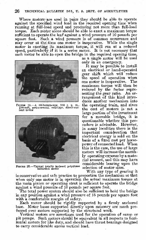
FiouEE 24.—A 60-horsepower, 550 r. p. m., 230-volt, series-wound, mill-type, direct-cur- rent motor
Where motors are used in pairs they should be able to operate against the specified wind load in the required opening time when running at full-load speed and producing not more than full-load torque. Each motor alone should be able to exert a maximum torque sufficient to operate the leaf against a wind pressure of 10 pounds per square foot. Such a wind pressure is of common occurrence and may occur at the ¿time one motor is inoperative. While the single motor is exertiiçig: its maximum torque, it will run at a reduced speed, particulatiy if it is a series motor. It is not necessary that each motor be able .to open the bridge in the required opening time,
as a single motor will be used only in an emergency.
It may be possible to install an electrical or hand-operated gear shift which will reduce the speed of operation when one motor is inoperative. The maximum torque will then be reduced by the factor repre- senting the gear ratio. An ar- rangement of this kind intro- duces another mechanism into the operating train, and since the cost of motors is not a large portion of the investment for a movable bridge, it is questionable whether this pro- cedure is advisable. However, in many localities there is the important consideration that electrical energy is sold on the basis of a fixed cost per horse- power of connected load. When this is the case, the use of large motors will increase the month- ly operating expense by a mate- rial amount, and this may have considerable bearing upon the selection of motor sizes.
With any type of gearing it is conservative and safe practice to proportion the mechanism so that when only one motor is in operation the actual maximum torque at the main pinion or operating strut is sufficient to operate the bridge against a wind pressureof 10 pounds per square foot.
The total power system should also be sufficient to hold the bridge in any position against a wind pressure of 15 pounds per square foot with a comfortable margin of safety.
Each motor should be rigidly supported by a firmly anchored base. Motor bases supported directly upon masonry are much pre- ferred over motors supported by the structural work.
Vertical motors are sometimes used for the operation of sump or pit pumps. Such motors should be equivalent in all respects to hori- zontal motors for like duty, and should have thrust bearings designed to carry considerable excess vertical load.
FIGURE 25.—Typical totally Inclosed polyphase induction motor

ELECTBICAL EQUIPMENT ON MOVABLE BRIDGET 27
It is desirable that there be supplied with each motor as spare parts one set of brushes, one armature complete with shaft and commutator or one rotor complete with shaft and slip rings, one set of field coils or stator coils, and one set of bearing linings.
Figures 24 and 25 show motors suitable for movable-bridge service. The following data should be included in the specifications for
any motor needed for a movable bridge in order to furnish the basis for an intelligent bid:
(1) The character of the current (whether alternating current or direct current).
(2) The voltage. (3) The frequency (cycles) and number of phases (if alternating current
ÎS used), (4) For direct-current motors/ the type of winding (whether shunt wound,
series wound, or compound wound), and for alternating-current motors, the type of rotor (whether squirrel-cage, high-resistance rotor type, or wound- rotor type).
(5) The type of frame (whether open, semiinclosed, or totally inclosed). (6) The type of insulation (whether special moisture-proof insulation need
be provided). (7) The rating in horsepower, giving the basis of rating in terms of tempera-
ture rise and duration of test (for example, a rating of 40 horsepower on the basis of a temperature rise of 50° C. for 30 minutes when subjected to the standard tests of A. I. B. E. ).
(8) The speed of the motor i^ revolutions per minute at full load and, in case of alternating-current motors, the synchronous speed as well.
(9) The full-load torque, the maximum starting torque, and the maximum running torque values.
It is probably well to provide that each motor shall be tested at the contractor's expense, and at the manufacturer's plant, and that a certified copy of the results of such tests be furnished the engineer or purchaser.
CONTROL AND INTERLOCKING OF OPERATIONS
A complete control system for any movable bridge must be de- signed to perform several separate and distinct functions, as follows : (1) The regulation and control of the power plant proper, (2) the proper control of sequence or interlocking of the various operating steps, and (3) the safeguarding of the structure and its operating mechanism.
The first functiton, or power-plant regulation, comprises four sepa- rate features—starting, acceleration, deceleration, and reversal. The control equipment for starting must be such as to effect a transference of load to the power plant without undue shock or jar, and without introducing torques or load currents in excess of those for which the plant is designed. Acceleration and deceleration must be effected at a rate necessary for safety and traffic efficiency. This rate is, of course, influenced to a large extent by the character of traffic for which provision must be made.
^ The second function is that of controlling the succession of opera- tions so that they can occur in only one predetermined order.
The third function involves safeguarding the structure by mechan- isms and devices such as limit switiches, automatic stops, indicators, buzzers, and seating devices, so that the various portions of the struc- ture are protected from overload, overtravel, or undue impacts and shocks or vibrations. Each of the above functions will be discussed in detail.

28 TECHNICAL BULLETIN 2 6 5^ XJ. S. DEPT. OF AGRICULTUEE
Attention is called to the appendix at the end of the bulletin con- taining definition of terms and manufacturers' specifications for vari- ous electrical appliances.
CONTROL AND REGULATION OF ELECTRIC MOTORS
The regulation of electric motors includes starting compensation, speed control, reversal, overload protection, and protection against excessive acceleration.
STARTING COMPENSATION
Starting compensation may be defined as the means employed to counteract the tendency toward destructively high currents m the motor during its initial and early acceleration from a point of rest. The need for compensation has been discussed in connection with motor characteristics. Starting compensation may be said to be the electrical equivalent of a friction clutch—it is the method by which the load is eased onto the motor at starting.
Small motors of either direct-current or alternating-current type do not require starting compensation and full-line current can be applied by means of an ordinary switch. As the duty increases, compensation at starting becomes a necessity unless the size of the motors in comparison with the load be greatly increased. It must be remembered that, aside from commutation, starting compensation is only necessary to protect the motor against excessive currents, and if the motor windings were to be built large enough to withstand such currents, starting compensation could be dispensed with. Some of the larger manufacturing companies are now building motors of rather large horsepower which have been designed for direct-line connection at starting. However, for general practice in movable- bridge design, the following rules are suggested.
Motors for roadway gates, counterweight pit pumps, and other light duty may be directly connected to the line at starting. Motors for end wedges of swing spans, tail locks of the toggle type for bas- cule spans, heavy traffic barriers, bascule center locks, or other like intermediate duty where the load is ordinarily light, but due to a possible jamming or sticking of the mechanism may have to carry abnormal loads occasionally, should preferably be provided with some starting compensation. Motors for hoisting or swinging the leaf or leaves of a movable span, are under a service that necessi- tates provision of this character in all cases except for very small structures.
Starting compensation for direct-current machines is effected by a reduction in the voltage or by interposing resistance in the arma- ture circuit which is cut out in successive steps or stages as the motor attains speed. Starting compensation for alternating-current motors is effected by a reduction in line voltage or by a group of resistance steps in the rotor or secondary circuits. (For a further discussion see p. 57.)
SPEED CONTROL AND REVERSAL
Speed control of direct-current motors is effected by varying either the field or armature currents as previously explained, while in

ELECTRICAL EQUIPMENT OK MOVABLE BlUDGES 29
alternating-current motors it is effected by varying the resistance in the rotor or secondary circuits.
Direct-current motors are reversed by reversing the polarity of the armature current with reference to the field current. Alter- nating-current motors (polyphase induction motors) are reversed by reversing the phase sequence of the stator coils.
OVERLOAD PROTECTION
BALANC N6
IM j
SERIES COIL C
Mtítíft-f— •^ CORE D
HOLDING RELAY F# Uid-
IM
- HOLDING RELAY CIRCUIT
START BUTTON RESET
FIGURE 26.—Diagram of a series with electric automatic reset
relay
Motors are protected from overload by a circuit breaker or over- load relay and this function has already been discussed. These devices are wired in series with the armature circuit of direct- current motors and in series with the stator or primary circuit of alternating-current motors.
There are several general types of overload relays in common use. In one type the relay controls a latch on the main switch, and when the latch is released the switch opens. The relays them- selves can reset instantaneously, but it is necessary for the operator to reclose the switch manually. This type of relay is applied to circuit breakers or switches installed on the main switchboard in the in- coming line. They furnish protec- tion to the circuit as a whole, but not to individual motors (if there are two or more motors on the line), since they must be adjusted for the combined load of all connected apparatus. In a direct-current cir- cuit or single-phase alternating-current circuit only one lead wire need be opened to break the circuit. For a 3-phase circuit two of tlie leads must be controlled to insure against the possibility of a motor operating on a single phase with one of the leads open.
In another type of apparatus a pilot circuit operating a magnetic contactor in the main line is controlled by contacts on a line relay. This type of apparatus is generally installed in the circuits of single motors. In some installations it is necessary to close the relay con- tacts by hand or by a magnetic device controlled by a push button located at any desired point. Use is also made of relays which open and then automatically close. While the auxiliary circuit is momen- tarily open the power supply is shut off, but can be reconnected by means of another auxiliary circuit controlled by a push button or other reset point.
Figure 26 is a schematic wiring diagram for an overload relay with electrical automatic reset and auxiliary push-button start sta- tion to protect a direct-current motor. The breaker circuit is nor- mally held in contact at point A by means of the balancing or reset relay P shunted across the line. When the current in the power lead reaches a certain value series coil C exerts a pull on its core D sufficient to overcome the attraction of the relay P and opens the cir- cuit at point A. This deenergizes magnet coil E, opening the main power circuit at F. An instant later (almost instantaneously) con- tact A is remade (since series coil C is deenergized with the opening

30 TECHNICAL BULLETIN 26 5. U. S. DEPT. OF AGRICULTURE
CROSSHATCHED AREA INDICATES OVERLOAD CURRENT PRODUCED BY TOO RAPID ACCELERATION
of circuit at F), but this instant has been suflSicient to open up the shunt circuit G-H, causing the core on the holding relay to drop, opening the circuit actuating magnet coil E at K. All circuits are reestablished by pressing the button M.
If a spring is attached to the contact arm A to reestablish contact when coil C ceases to function, the arrangement is known as an automatic spring reset. If the effect of gravity is substituted for spring tension, the type is known as the automatic gravity reset type.
PROTECTION AGAINST EXCESSIVE ACCELERATION
Where successive resistance steps are cut out with a controller or master switch, excessive currents will be induced if the action is
too rapid. As each resistance step is cut out, armature or rotor cur- rents increase, causing the motor to speed up. As the motor speed in- creases these currents drop back due to the increased back e. m. f. in the case of direct-current motors and to the decreased slippage of the rotor in the case of induction motors. In
CURREÍIT LIMIT either case the current variation as successive resistance steps are cut out is as indicated in Figure 27. If the controller or master switch handle be moved over at just the right speed, the current varia- tions may be kept along the line ABCDEFGH. If this handle is thrown over too rapidly, however, the current variation graph assumes some position such as ABCIJKLH,
FIGURE 27.—Effect on speed and current resultiuff in an CXCeSsive Current, of normal and rapid reduction of start- rr^ • j ^ i 14.' ing resistance io aviod cxccssive acceleration,
it is advisable to install in the main motor circuit (armature circuit of direct-current motors, and either the rotor or stator circuit of alternating-current motors'^) current limit relaya which operate on each resistance step and hold open the circuit, cutting out the next resistance step until the power current has dropped to a certain predetermined value. These relays are quite similar in general construction to overload relays consist- ing of an electromagnet in series with the armature circuit or the rotor or stator circuit.
As any step of resistance is cut out the power current steps up. This current passes through the relay and while above a certain value it exerts a pull against the relay armature or core sufficient to open an auxiliary circuit which is wired in such a manner that electromagnetic controls hold open all additional resistance steps on the controller or master switch. No matter how far the controller or master-switch handle is now thrown over, no further resistance can be cut out. The auxiliary circuit is held open by the current-
CORREC"
TOO RAPID ACCELERATION
TIME AND SPEED
^The stator currents obviously decrease with any decrease in rotor currents due to the decreased demagnetizing effoct.

ELECTRICAL. EQUIPMENT ON" MOVABLE BRIDGES 31
limit relay magnet against the pull of a spring (or a weight or another relay coil), and as the motor speeds up the power current decreases to a point where the spring overcomes the inagnetic attrac- tion and the relay again closes, rencfering the next point on the con- troller or master switch available for cutting out another resistance step. As the next step is cut out the cycle is repeated. Current- limit relays are generally adjustable and can be set for any value of current within the range for which they are designed.
The present discussion has been limited to an outline of the func- tions necessary for a proper regulation and control of motors. Selec- tion of equipment, wiring, and arrangement will be considered later.
CONTROL OF SEQUENCE AND INTERLOCKING OF OPERATIONS
The next question which logically presents itself is that of con- trolling the sequence of the various events constituting an operating cycle. As these events are somewhat different for different types of movable bridges, the discussion must be segregated by types, each of which will be discussed in brief detail.
DOUBLE-LEAF BASCULE BRIDGES
A complete operation cycle for this type of structure comprises the following events which should be performed in the order given. Opening :
Operation of warning signals and signs. Closing of remote gates, if any. Closing of near gates, traffic barriers or opening of derails. Unlocking the leaves. Opening the span.
Closing: Closing the span. Locking the leaves. Raising the traffic barriers, near gates, or closing of derails. Raising of remote gates.
The warning signals may be sirens, whistles, and bells for audible warning, and semaphores and lights for visual warning. The bells and sirens may be operated during the operation of the gates, or may cease before the gates are lowered. In general, a traffic bell or gong ringing during the operation of gates is not objectionable, but a prolonged siren is apt to drown out signals from the river craft so that it is perhaps better to stop the siren before the gates are lowered. The traffic-bell circuit may be cut into the gate circuit so that it is impossible to operate the gates until the traffic-bell cir- cuit is closed and the traffic bell may be made to sound during the entire operation of the gates. The necessity for this precaution will depend on traffic conditions. Semaphore arms or lights may be electrically interlocked so that they must be set to danger before the gates can be operated. The semaphore can be arranged to close an ordinary door-type switch in the gate circuit when the semaphore is in the warning position. The traffic-light circuit can be arranged to operate a relay which closes the gate circuit only when the light circuit is energized.
Semaphore arms and traffic lights can be arranged to operate on a circuit which is closed the instant the gate moves from its fully open position. Both of the above described arrangements are indicated- schematically in Figure 28. This diagram shows buttons for short-

32 TECHNICAL BULLETIN 26 5, U. S. DEPT. OF AGRICULTUKE
circuiting the switches controlled by warning devices, so that the gates can be operated when there is a failure m the interlocked cir- cuits. Interlocking of controls serves an admirable purpose, but, carried to excess, and without provision for cutting out the various
• SHORT-CIRCUITING BUTTONS
LIGHT SWITCH TRAFFIC LIGHTS
BELL IL
GATE MOTOR
'-^>^
^
/ / / / / / / / / / / / / / / /
BELL-CONTROL SWITCH
TRAFFIC LIGHTS AND SIGNALS
;/ fV/ SNAP SWITCH CLOSES CIRCUIT AS SOON AS GATES
Jï22tf*-^^ARE STARTED DOWNWARD
\r; -TO POWER LINES FIGURE 28.—Method of interlocking control of gates and warning devices
REVERSING ¿WITCH- OUTBOARD BEARING
CENTER-LOCK MOTOR
CENTER-LOCK MASTER SWITCH UTí
CONTACT FOR LEAF INTERLOCK FOR CEN- TER-LOCK MOTOR
\MAGNETIC COIL \
1[ALJER_N_ATE LOCATION FOR LEAF INTERLOCK
o^.^Q O^V. ^<f<.
INTERLOCKING WITH SAFETY DEVICES WHICH SHOULD BE OPERATED BEFORE CENTER-LOCK MOTOR STARTS
-JUUUl
i\
N
\
T T T T*— SHORT-CIRCUITING SWITCHES
FIGURE 29.—Wiring of controls on the center-lock motor
steps in case of emergency, it may cause dangers as great as those it is intended to avoid.
The closing of near gates, traffic barriers, or derails should not be possible until the remote gates are closed.
The leaves of a bascule bridge are locked together in their closed position by a center-locking device, and in addition, tail locks are

ELECTRICAL. EQUIPMENT OK MOVABLE BRIDGES 33
sometimes used. These devices are generally operated through a master switch or controller which should be arranged so that they can not be released until all signals, gates, and barriers have been properly operated. (Fig. 29.)
The main leaves are generally controlled by a master switch which should be wired through a contact on the center lock which is closed only when the center-lock pin is fully released; otherwise a careless operator might cause serious damage by attempting to raise the leaves before they were unlocked. (Fig. 30.)
_^ ^ ^_^ .... . DRIVEN
^' ' CENTER-LOCK MASTER SWITCH
CONTACT ON CENTER -LOCK MASTER SWITCH MADE WHEN HANDLE IS THRWN TO DRAW-LOCK POSITION
FIGURE 30.—Interlocking of main motor and center-lock pin
In closing a bridge the leaves are lowered to a bearing at an out- board or live-load shoe at the stream edge of the abutment and at a rear bearing or anchorage. (Fig. 29.) At either of these points a device may be installed to complete the circuit for the center-lock or tail-lock motors in the " drive " direction, so that these devices can not operate in that direction until the bridge leaves are down, fully seated, and correctly aligned. Whether this particular interlocking is essential to safe operation is an open question. If this interlock is not provided, the center or tail locks may be driven while the bridge is in the open position. This in itself is not particularly^ objection- able, since the main motor circuit is wired so as to be inoperative except for those devices fully open. (Fig. 30.) There is, however, danger of jamming the center and tail-locking devices by trying to
04559°—31 3

34 TECHNICAL. BULLETIN 265, U. S. DEPT. OF AGRICULTURE
drive them with the leaves not fully seated, and in exact vertical alignment (except for certain types of locks designed to draw the leaves together for the last inch or so of their movement). If it is possible to operate the lock pins with the leaves partly open, provision should be made for making the roadway gates, traffic barriers, etc.. Inoperative with the leaf up ; otherwise, the gates and barriers can be raised (lock-pin interlock is closed) with the leaves partly or fully open. If, on the other hand, the contactor for the gate and barrier circuits is operated through a pair of contacts, one on the pin and the other on its mating seat, then the leaves must be seated and the pins driven before the barriers and gates can be cleared for traffic. (Fig. 30.)
Figure 31 is a diagram of a centerlock contact for a barrier or gate motor circuit. If the two contact points are at A and B the barrier circuit can be energized whenever the pin is driven forward, regard- less of the position of the leaves and additional interlocking should
be provided on the live-load shoes ''°''"LOTK SOCKET or anchor column. If the contact
^^^cKsocKET points are at A and C no additional ^^^^^^>^ contact on the leaves are necessary.
^"^^^^^^^ ^^ ^^^ ^^^^ ^^ barrier circuit is interlocked with the leaves, but not with the center or tail lock, it is possible to carelessly permit traffic over an unlocked span and thus produce live-load stresses not pro- vided for in the design.
The sequence of the remaining FIGURE 31.—Methods of interlocking cir- ^^,,„„j.-^^ "^ /_.^,.^^^^4- ^-C u«««4^n«^ cuit to barrier or gate motors operations (movement ot bamers,
near gates, derails, remote gates, etc.), is controlled by arranging each circuit so that it is open until the operations which should precede have been completed.
Where circuits carry only low power as in the case of gates and signals, the control switches may be operated direct, but for high power they should be operated magnetically through a control cir- cuit. (Fig. 30.) As an example of an incorrect arrangement, sup- pose that contact A in Figure 30 is placed on the centerlock master switch; then if the roadway gates or barriers are open, the circuit to the centerlock motor is open and the handle on the centerlock switch can be thrown to the draw-lock position, but the pin will not be drawn. However, this removes the interlocking on the circuit to the main hoisting motors. With such an arrangement a careless operator might cause serious damage.
SINGLE-LEAF BASCULE BRmGES
The sequence of operations for this type of bridge is much the same as for the double-leaf type.
Heavy, positive-action traffic barriers are essential as the open end presents a traffic danger more acute than in the case of the double-leaf type where the opened leaves act as effective traffic barriers.
ELECTRICAL EQUIPMENT OK MOVABLE BRIDGES 35
The tail lock at the rear end of a single-leaf bascule may be arrg,nged in several ways, but the manner of interlocking does not differ from that of the center lock or tail lock of a double-leaf span.
SWING-SPAN BRIDGES
The operating cycle of a swing span includes the following : Opening :
Operation of warning signals and signs. Closing of remote gates. Closing of near gates, traffic barriers, and opening of derails. Release of center wedges, if any.^ Unlatching of span. Withdrawal of end wedges. Opening span.
Closing : Closing the span. Closing latches. Driving of center wedges. Driving of end wedges. Raising of traffic barriers, near gat^s, etc., and closing of derails. Raising of remote gates.
Interlocking of the various steps in moving a swing span follows the principles which have been outlined. If there is a large volume of traffic some method of protection in addition to the ordinary road- way gate is almost imperative.
Center wedges are used on center-bearing swing spans, and their function is that of a pair of live-load shoes at the central support.. These wedges are driven to a snug bearing only and take no dead load. Sometimes they are riiechanically connected with the end wedges so that all three are operated simultaneously. If this is done, some method must be provided to prevent overdriving which will make them hard to release. If the center-wedge system is separately operated, it should preferably be interlocked with the traffic gates and barriers, to prevent a release of the center wedges with the roadway open to traffic. This would expose the center pivot to live-load stress, and allow the span to rock laterally under traffic.
The end wedges must also be interlocked with the gate and barrier mechanism or else live load over the span with the wedges released will cause hammer at the supports and induce excessive chord stresses. It might also cause severe impact stresses in end floor beams and hip vertical truss members.
It is not considered necessary or advisable to interlock the latching device with any other device. It may be arranged to release simul- taneously with the end wedges and be operated by the same mechan- ism or it may be operated independently. In any event, unlatching the structure can cause no harm. If the wedges are driven the struc- ture is stable without the latch, and if they are released, the end- wedge and center-wedge interlocks insure that the traffic gates and barriers have been properly set.
The circuit to the main swinging motors should contain a magnetic switch controlled by a circuit interlocked with both end wedges and center wedges, and preferably all gates and barriers as indicated in Figure 32.
2 The term " wedge " is used to indicate any type of lifting device used at the center or end supports of a swing span regardless of the mechanical principle upon which it operates.

36 TECHÍsTICAL BULLETIN 2 6 5^ U. S. DEPT. OF AGEICULTUEE
When the span has been swung to the closed position and the latches released, the next operation is the driving of the center wedges and end wedges, and it is not necessary to interlock the power circuit actuating these mechanisms with the span movement. In such a case the wedges can be driven when the span is open, but the main motor circuit is interlocked with the end wedges and the span can not be closed under power until the wedges are drawn and there is, therefore, no danger of swinging the span against a driven wedge. The omission of this interlock is sometimes a convenience, as the wedges can be driven back and forth for inspection while the structure is over the draw rest, which is a convenient inspection
POWER LINES -7-
m TURNING
MOTOR
SHORT-CIRCUITING BUTTONS NOT SHOWN
FIGURE 32.—Interlocking devices controlling wedge motor and turning motor
point. Of course, even with the interlock, this same operation may be performed with a short-circuiting button.
The circuits actuating all gates, barriers, and signals, and any derail mechanism, must be interlocked so that the roadway will be opened only after the wedges are fully driven. If the wedges are not interlocked with the span movement, then the gate and barrier circuits must be interlocked with the span itself so as to become operative only after the span is closed and seated. Other- wise when the span is open the wedges can be driven and all gates and other roadway protection can be operated.
Where several safety operations follow each other in sequence, it is sometimes desirable as an additional precaution to double or cross interlock the remote devices; for example, interlocking the remote gate power circuit (for clearing) with both the traffic barrier and the end wedges ; thus providing two interlocks, either of which will safeguard the operation.

ELECTRICAL EQUIPMENT ON MOVABLE BRIDGEÖ 37
Figure 32 is a schematic layout for the main-motor and wedge- motor interlocks on a typical swing-span installation. For sim- plicity, the center wedge has been omitted, the latches are assumed as hand operated and are not interlocked, and only two traffic pro- tective devices (an arm gate and a vertically moving barrier net) have been considered. It should be pointed out that Figures 28 to 32 are not wiring diagrams, but merely schematic layouts used to illustrate certain general principles in electric interlocking. Much of Jbhe detailed circuit wiring has been omitted for the sake of sim- plicity. Complete wiring diagrams will be discussed in later pages.
The degree to which a swing bridge is protected by means of interlocking and other protective devices from mistakes in operating is a factor vitally affecting its service life. For example, a careless attempt to swing an unprotected leaf with either the center or the end wedges driven or with the latch bar in place might easily result in stalling of the power plant, burning out of clutches, stripping of gears, twisting of shafts, damage to wedges, shearing of latch bar, or overstress in the lower chord of the span.
Overdriving of the end wedges must be safeguarded against by suitable travel limiting devices (p. 39), otherwise the span may be raised above its normal position; thus tending to introduce dan- gerous stress reversals in some of the truss members, or injuring the wedge-driving mechanism. Another method of protection is to use a torque current relay in the motor circuit.
Underdriving the wedges results in a difference in floor elevation at the junction of fixed and movable spans which causes heavy im- pact on end floor beams, and hip verticals. It also tends to cause overstresses in various chord members due to the increased canti- lever action.
If the wedges are not released the full amount, there is quite apt to be an interference as the wedges swing off their pedestals and pass over the other shoe. As the wedges swing away from their supports there is apt to be ia slight dropping due to the lost motion in the guide castings, and if conditions are such that the upper chords are at a materially higher temperature than the lower chords, the normal swinging clearance may be curtailed to such a degree that, unless the wedges are fully drawn, the inner wedge strikes the outer shoe as it swings around and over it, with destructive effect on wedges and serious impact stresses in the truss members proper.
VERTICAL-LIFT BRIDGES
A complete operation cycle for this type comprises the following : Opening :
Operation of warning signals, signs, lights, etc. Closing of remote gates. Closing of near gates, traffic barriers, and opening of derails. Unlocking the span. Lifting.
Closing: Closing the span. Locking or latching. Raising of near gates, traffic barriers, and resetting of derails. Raising or clearing of remote gates.

38 TECHNICAL BULLETIN 2 6 5^ IT. s. DEPT. OF AGRlCULTXTRE
These operations are interlocked in much the same manner as the other types and need not be discussed in detail. Sometimes the span locks are omitted, in which case the main hoisting motors should be interlocked through the roadway signals.
GENERAL RULES FOR INTERLOCKING
Each interlocking problem is, of course, more or less of an indi- vidual one. Traffic density, sight distance, and other factors may modify the arrangement of details. In general, however, the fol- lowing features of interlocking are necessary.
(1) Each control circuit should be so wired that the prior opera- tion must be actually and completely performed before it becomes operative.
(2) Interlocking contacts must be positive in action and so located as to minimize the danger of short-circuiting or deterioration from moisture, ice, or mechanical injury.
(3) Contacts should preferably be made by a spring or snap device rather than by a sliding motion in order to avoid sparking and injury to contact points or tips, although a certain amount of wiping motion may be advantageous in tending to keep the contacts clean and bright.
(4) Make-and-break contacts for interlocking should not be placed directly in a heavily loaded power line but rather on an auxiliary or control circuit wired to operate a magnetic contactor cut into the main power line.
(5) Cross interlocking of operations should be provided wherever there is a danger due to the possibility of a failure of one phase of operation.
(6) Short-circuiting buttons or switches should be provided to permit operation in the event of a failure of any portion of the interlocking mechanism.
(7) In general, the entire interlocking arrangement should be as simple as possible, compact, sturdy, protected to the maximum possi- ble extent, and so designed as to eliminate as far as possible every conceivable traffic hazard and every contingency or event that might expose the structure to undue stress.
PILOT AND INDICATING DEVICES
In addition to the interlocking proper, added protection may be obtained by means of suitable indicating devices. A system of lights or a moving indicator should be provided to indicate to the operator by day or by night the exact position of the leaves.
All circuits to roadway traffic lights and signs and navigation sig- nals should light a pilot light in the operator's house to indicate whether or not they are are operating. The position of all traffic gates, roadway barriers, derails, wedges, and center locks should like- wise be indicated by pilot signals or other satisfactory devices.
The seating of the leaves of a bascule span should be indicated to the operator by a buzzer signal controlled by contacts which are closed when the structure comes to rest upon its live-load bearing or against its rear anchorage lug. Such an arrangement is particularly useful in bringing the far leaf of a bascule span to a correct seat

ELECTBICAL EQUIPMENT ON MOVABLE BRIDGES • 39
on a dark or foggy night. A seating indicator is desirable but not quite so necessary with the other types of movable spans. In the case of a swing span, a latch-pin contact in a buzzer circuit will serve this purpose and be distinctly advantageous.
PROTECTIVE AND TRAVEL LIMIT DEVICES
Another function of a control system is that of protecting the structure itself and its operating mechanism. This is generally ac- complished by means of limit switches so designed as to cut off power from the motor circuit at a certain selected point of travel of the mechanism protected. These limit switches may also be arranged to apply brakes where necessary, and to complete circuits of pilot lights indicating the position of the mechanism.
It is essential that a main-leaf limit switch be provided on bascule and lift spans at both the upper and lower portions of travel. Gen- erally these limit switches are set some little distance from the actual extreme upper or lower limit. When it is necessary to operate the structure above the upper-limit switch a short-circuiting button makes it possible to put power to the span. The lower-limit switch is also provided with a short-circuiting button and sometimes with a seating button by means of which the structure can be gently seated under power.
It is not particularly necessary to provide a main-leaf limit switch on swing spans as the span will do no damage if it swings past its correct position, except perhaps to shear a latch pin, and this danger is generally eliminated by other means.
Centerlocks, taillocks, wedges, and other devices are generally pro- vided with limit switches at one or both limits of travel. The mech- anism of commercial roadway gates and traffic barriers generally includes a limit switch which not only cuts off current but automati- cally resets the contacts for reverse movement. All of these features will be discussed in more detail later on.
The question of control has been discussed in a rather general manner, avoiding any discussion of methods and appliances, since it appeared advisable to present a general picture of the problem before discussing details. The following pages will present a more detailed consideration of the question and the last portion of the bulletin will present a description of actual wiring diagrams for con- structed bridges.
ELECTRICAL INTERLOCKING AND CONTROL ASSEMBLIES
An assembly for electrical bridge control is largely a specialized arrangement of standard parts. Solenoid brakes, circuit breakers, overload relays, current-limit switches, magnetic contactors—these and other like devices make up the installation. Most of these devices are standard commercial units and this is a desirable feature of elec- trical control. There are many instances which appear to call for specially designed control devices, but a little study will often indi- cate that a special arrangement of standard equipment will be ade- quate. In the paragraphs which follow the principal items of equip- ment necessary for an installation will be briefly described and a few

40 TECHNICAL BULLETIN 2 6 5, XJ. Si DEPT. OF AGKICULTUEE
essential points with reference to their design and general construc- tion will be discussed. ■ ; .
TYPES OF ELECTBIC-CONTEOL SYSTEMS
The three general types of electrical-control systems are manual, full magnetic, and semimagnetic.
In the manual-control system all circuits are operated directly by hand controls.
With magnetic control the circuits carrying heavy current, such as motor circuits and brake circuits, terminate on a magnetic control board. Magnetic contactors, as shown in Figures 28 and 30, are
mounted on this board. The power circuits and other heavy current leads terminate on this board in one or more copper contact points such as at B in Fig- ure 33. These con- tacts are made and broken by an electro- magnet (fig. 33 A), which is actuated by a separate control cir- cuit extending to the operator's station, and terminating in what is known as a master switch.
A master switch of the drum type (fig. 34) may be used, or the control circuits may be operated by push buttons, hand levers, or like devices.
The advantages of magnetic! control are : (1) The elimination
of long lines carrying heavy current and requiring large wire, thus effecting a sav-
if},
B C . A
^ ^ jZ^i D
\ F
-»- Í "ai
FIGURE 33.—A typical magnetic-contactor oanel. The mag- net coil, A, is wired in series with the control circuit and attracts its armature revolving the square shaft, D, in its bearings and malsing the main contact, B. The blow-out coils, B, create a magnetic field between the sides of the arc chutes, C, stretching out the arc and rupturing it quickly as the contactor tips, B, are sepa- rated. The braided copper strips, F, carry the current from the line to the contactor tips
ing in copper. (2) The elimination of cumbersome controlling de- vices in the operator's quarters. The circuits necessary for the opera.- tion of any movable bridge are numerous, and if the main circuits are all extended into the operator's quarters the devices for control- ling them occupy considerable space. On the other hand, control circuits may be operated, at least in part, by push buttons or other devices Avhich aref more economical of space. (3) The magnetic sys- tem is safe and flexible in operation and lends itself more readily to interlocking.

tetÉCÍBlCAL EQUIPMENT OíT MOVABLE BRIDGES 41 The cost of full magnetic control is somewhat higher than that for
manual control owing to the additional cost of magnet contractors. This increased cost, however, is partly offset by the saving in copper by dispensing with long lines carrying heavy currents.
The semimagnetic-control type is a compromise between the two systems of control. Some of the power circuits are opened and closed direct from the operator's station, while others are magnetically operated.
A system of full magnetic control consists of a main switchboard, a magnetic or remote-control board, and an operator's control board.
FIGURE 34.—Typical arrangement of master switches on a double-leaf bascule bridge. The large master switches control the leaves, while the small one in the center Is
: for center-lock control. Note the geared-type vertical master switch handles, the ! forged copper fingers and arc deflectors shown in the master switch Interior. A i battery of indicator lights is mounted between the windows. At the right is the ■■ emergency hand-brake lever. The short-circuiting buttons for the leaf-limit : switches are marked "A"
I SWITCHBOABD ASSEMBLIES
The main switchboard may be located at any convenient point on the structure. It is generally located near the operator's station in order to have the meters and instruments conveniently accessible. The main power circuits must run from the main switchboard to the reniote-control board, and thence to the motors or other appliances which they actuate. These two boards should be so located as to give a convenient arrangement for power wiring. The circuits from the remote-control board to the operator's bench carry only low power and it is not particularly essential that the operator's station be close to other equipment. If the main switchboard is located at some dis- tance from the operator's station and if it is desirable that certain of the instruments (voltmeters, ammeters, and the like) be accessible to

42 TECHNICAL, BULLETIN 26 5, V. S. DEPT. OF AGElCtJLTUEE
the operator, these may be mounted upon a separate panel and placed near the operator's station. The main switchboard should have space for all necessary instruments, switches, circuit breakers, cut-outs, fuses, and other apparatus, and each device should be easily accessible.
FiGtiEB 35.—A partial view of a typical switchboard Installation showing method of mounting and labelling circuit breakers, overload relays, ammeters, voltmeters, knife switches, and cartridge-type fuses
Controls and indicators should be marked with permanent labels covered with celluloid or other similar material. Figure 35 shows a portion of a typical switchboard installation.
In general, the main switchboard should have the following equipment :

ELECTEICAL EQUIPMENT ON MOVABLE BRIDGES 43
(1) A suitable circuit breaker. Oil-type switches are used for this purpose, with provision for an inverse-time-element ^ overload release, and suitable low-voltage protection. Carbon-type circuit breakers (3-pole for alternating currrent and single-pole for direct current are also used for this purpose. These switches are placed on the incoming line (the power supply) and when open the current is cut off from all electrical units. The current rating for such a switch should be sufficient to cover the entire power demand.
If alternating current is used the incoming line is generally pro- tected by a reverse-phase relay which opens the main power circuit in case of phase failure or reversal.*
(2) A suitable system of voltmeters and ammeters. (3) A system of inclosed fuses, preferably of the cartridge type
for the protection of all circuits. (4) A system of knife switches for disconnecting each individual
circuit. REMOTE OB MAGJíETIO CONTROL BOARDS
The remote or magnetic control board should, in general, contain the following panels (fig. 57) :
(1) A line switch for each power circuit. ¡2) A line switch for each control circuit. (3) Individual disconnecting switches for each motor circuit. (4) A system of overload relays. (5^ A system of current-limit accelerating relays. (6) A system of mechanically interlocked magnetic reversing
contactors for each group of reversible motors. (7) A system of magnetic contactors for each of the solenoid
brakes. (8) A battery of magnetic-accelerating contactors for speed con-
trol and starting compensation. The magnetic-control board should, in general, be located as near
as possible to the main motors or in the path between them and the mam switchboard, so as to avoid excessive length of large wire. Where wedge motors, lock motors, and similar units are operated by magnetic control, a separate magnetic-contacting panel may be in- stallç4 near these motors or the panel may be a part of the main magnetic-control board. Lock and wedge motors, in general, do not need any devices for speed control. If they are to be reversed, a reversing contactor must be provided, or else a reversing switch installed on the operating bench.
In general, the aggregation of individual contactor, switch, and relay panels which constitute the remote-control board should be
' The term " Inverse time element " is applied to an arrangement in circuit breakers or overload relays which limits the amount of current which can be carried without opening of the circuit in Inverse proportion to the time of application. This is accomplished by an oil dashpot, a thermostatic strip, or other suitable device. As an illustration, one oil-type device recently used is rated at 100 per cent (of calibrated current) for 30 seconds (witn- out opening circuit), 150 per cent for 7 seconds, 200 per cent for 8 seconds, and 300 per cent for 2 seconds.
*One type of reverse-phase relay consists of a set of series coils mounted behind a metal disk. The normal current flowing through these coils produces a magnetic field which tends to turn this disk. This turning torque is the resultant of the normal 3-phase torque, and a single-phase torque which acts in the opposite direction. The normal 3-phase torque is the greater and tends to hold the disk against a metal stop. In case of phase failure or phase reversal, the tendency to rotation is reversed, and the disk-rotates IQ the opposite direction tripping a contact which opens the line.

44 TECHNIOALi BULLETIN" 26 5, XT. S. DEPT. OF AGBICULTUEE
mounted on first-quality enameled slate or ebony asbestos lumber not less than ly^ mches thick. These individual panels are assem- bled and secured together and should be mounted on a rigid metal frame so located as to be readily accessible and convenient. Many remote-control boards are not located a sufficient distance from the adjacent wall to afford sufficient safety to the operator. The cur- rents used in bridge operation are heavy, and the remote-control
EMíCEH 36.—An interior view of an operator's bench or board ghawlng the interior arrangement of master-switch contacts and terminal boards and binding posts for
control circuits. Note the master-iswltch controls and the small brass flngei- levers for controlling auxiliary circuits.
board is a place of danger. There should be sufficient room behind this board to avoid the necessity of working in cramped quarters, of coming in contact with a circuit which may be grounded through the adjacent wall and its structural connections.
Each magnetic-control board should be equipped with one or more pilot lights mounted at convenient locations near the top of the board and lighted at all times except when the board is completely'deéner- gized. The line switches on magnetic-control boards are sometimes arranged so that they may be locked in the open position with a padlock. The lock-out switches are not needed except where it is necessary for the operator to come in contact with electrical circuits at points from which the magnetic-control board is not visible. ,

ELECTRICAL, EQUIPMENT ON MOVABLE BEIDGllS 45
In some cases the overload and current-limit relays on the remote- control board are placed in inclosed eases and locked to prevent tmauthorized persons from attempting to adjust them.
OPBBATOB'S CONTBOL BENCH
The operator's board or bench (sometimes called a manual) gen- erally consists of an assembly of the master switches, starting switches, push buttons, short-circuiting switches,- and any other ap- paratus for the control of the leaf or leaves. Figures 36,37, and 38 are typical installations.
The operator's bench is generally equipped with a sys- tem of indicators and lights to enable him to determine, at any time, the position of the leaves, center and end locks, lifts or wedges, roadway gates, traffic barriers, and other like protective devices. Pilot lights to indi- cate whether the vari- ous roadway and nav- igation lights are burning may be lo- cated on this board, or on the main switch- board, or on a sepa- rate board convenient to the operator. The lights for position in- dication are sometimes placed in an indicator box as shown in Fig- ure 39.
The operator's bench should be sub- stantially constructed of sheet metal and located at the point which will give the greatest degree of visibility of both roadway and waterway. Each switch or button on the oper- ator's bench should be suitably marked with a label and placed under a traiiiparent cover securely fastened to the bench. Sometimes the drum controllers or master switches are moimted against the inner edge öf~the bench as shown in Figure 34, and in other cases they are arranged as shown in Figure 36.
In the arrangement shown in Figure 39, the position of the leaves and ïocks is indicated by the flashing of a series of lights. Figure 40 shows a plan view of an operating bench for a double-leaf bascule bridge, using a different type of position indicator. Terminal boxes for all connections can be provided benea-th the bench and fuses fof.
FiGUBE 37.—An exceptionally compact arrangement of an operator's bench. Note the convenient mounting oí am- meter and Toltmeter, the battery of indicator lights, the arrangement of foiap switches, the position! indicator, and the foot pedal for " shorting " the leaf limit switches

46 TECHNICAL BULLETIN 2 6 5, U. S. DEPT, OF AGBICXJLTXJEE
the various light circuits can be installed there. The top of the bench provides space for the necessary short-circuiting buttons or levers for normal operation. If it is desired to install short-circuit- ing switches for cutting out any of the interlocking steps over
FlonBll 38.—Another view of the operator's bench shown lu Figure 37. arrangement for indicating the position of the leaves
Note the
pura IBRIDGEFREE^H
■ ■ LOCKS OPENI |wttMC[gSEfl|
FtGüEB 39.—signal light box for bascule-bridge control
a period of time, such switches should be placed beneath the bench where they can be locked.
The position indicator shown in Figure 38 consists of a model of the two bridge leaves mounted in a glass-covered recess. ' A small alternating-current wound-rotor motor (either single phase or poly.

ELECTEICAL EQUIPMENT ON MOVABLE BEIDGES 47
phase) is geared direct to the main leaf, and a similar motor is directly connected to the model. The rotor circuits of these two motors are connected together and the primaries are connected to the power line. Any movement of the leaf is, therefore, transmit- ted to the model. This device indicates the position of the bridge leaves quite accurately and is probably somewhat more desirable than a battery of lamps. Alternating current is required for its operation. One manufacturer of this device states that it is not as satisfactory as the dial-type indicator shown in Figure 40.
FiGüEE 40.—Plan view of operator's bench for a double-leaf bascule bridge, with a , dial type position Indicator
MAGNETIC CONTACTOR DETAILS
Magnetic contactors are used for the following purposes : For cutting out resistance steps in armature and rotor circuits;
for opening and closing motor circuits, and reversing the direction of current through motor windings; for operating brake circuits and other auxiliary devices; and for overload and current-limit protection.
There is a standard commercial product suitable for each of these types of service. Figure 33 shows the general arrangement of these contactors on a magnetic-control board. It will be noted that, in general, the main contacts are protected by means of arc schutes and magnetic blow-out coils * (although simple arc barriers are sometimes used on the lighter types), and are made and broken
' The magnetic blow-out coil is based on the principle that any conductor carrying cur- rent and in a magnetic field is subjected to forces which tend to deflect it from its posi- tion. If fhls particular conductor happens to be an arc formed when two contact points are separated while carrying current, the same law obviously holds. If, therefore, the contact tips B (fig. 33) are placed in a magnetic field produced by the blow-out coils, E, the arc formed when the tips separate will be bent upwards (if the polarity of the magnet coil is properly selected) and stretched out to a rapid rupture, thus protecting the con- tacts from disintegration. The polarity of the magnetic field must be such as to blow the src away from the contacts and not into them.

48 TECHNICAL BULLETIN 26 5^ U. S. DEPT. OF AGRICULTURE
by the movement of a square shaft which is revolved in its bearing b}^ the pull of an electromagnet wound in series with the control circuit for that particular panel. (Fig. 33.) There are a number of points in connection with the selection of these contactors which should be borne in mind, as follows :
(1) The contact tips should be of solid copper. (2) All contact tips, arc schutes, coils, springs, shunts, and like
details should be interchangeable where practicable. (3) All magnet coils should be impregnated with a moisture
proofing. (4) The contact tips should come together with a certain amount
of wiping motion in order to keep them bright and clean. (5) Reversing contactors should be mechanically interlocked so as
to prevent the closing of one circuit until the circuit in the reverse direction has been opened. Figure 33 shows a mechanical locking bar used with this type of contactor.
(6) Large flexible copper shunts should be used to carry current around the bearings.
(7) Each contactor should be provided with a spare operating coil and a spare set of contacts.
It is sometimes considered advisable to provide contactors with two separate line contacts arranged to operate in sequence so that if one " freezes " due to short-circuiting, the other is free to open the line. These contactors are generally wired to a push button, and when the double line contactor is used, the push button is so arranged that it can not be made to close the open contactor until the " frozen " contactor has been pried loose.
MASTER SWITCH DETAILS
The Electric Power Club defines the term " master switch " as fol- lows : "A device or group of devices which serve to govern the opera- tion of contactors or auxiliary devices of an electric controller." This organization also defines the term " manual controller " as follows : "A controller having all of its basic functions performed by hand." The term master switch may therefore be considered as including such devices as hand levers, push buttons, or any other device used to open or close an electrical-control circuit. It also, of course, in- cludes the standard drum-type master switch shown in Figure 34, which is the device to which the term master switch is generally applied. The drum-type manual controller is much the same in general construction as the drum-type master switch except that it is designed for heavy currents.
The drum-type master switch should be equipped with a large, easily gripped handle and fitted with a latching device to prevent accidental reversing of the motor, and a star wheel or pawl to indi- cate when the switch has been thrown to any particular point and to insure a positive contact at each point. Manual controllers and master switches handling heavy currents are generally equipped with arc schutes and magnetic blow-out coils while for lighter service arc barriers are placed between adjacent contact points to prevent arcing. Contacts are generally made by forged copper fingers against copper segments. The fingers and running segments should be easily renew- able, adjustable for alignment and pressure, and the contact should

ELECTRICAL EQUIPMENT ON MOVABLE BRIDGES 49
have a wiping or sliding motion to insure clean surfaces. The oper- ating shaft should be designed to eliminate the danger of any slip- page or turning of contacts on the shaft, and the entire construction should be rigid, well insulated, and protected from dust or mechani- cal injury. Master switches used to operate the main hoisting and turning motors are placed adjacent to, or as an integral part of the operator's bench, and are wired to the magnetic-control board.
In general, the master switch should be arranged to furnish for each direction (forward and reverse) one drift point, or point at which all electrically operated brakes are released with the motors idle. The second point each way starts the hosting or swinging motors, and the additional number of power points must be sufficient to operate the bridge from a position of rest to an acceleration such as will open the span in the specified time without shock or jar. In general, master switches should be equipped with auxiliary contacts which are wdred in such a manner as to render it impossible to start the motors or release the brakes once the push-button circuit has been broken, without first moving the master-switch handle back to the drift point, or perhaps the first power point. This device is known as a " master-switch reset," and is generally wired through circuit breakers and other protective devices. The necessity for such pro- tection is obvious. If, due to an overload or for any other reason, power should be cut on with the master-switch handle on a forward notch of power, a reestablishment of power through any of the reset devices (such, for example, as the start push button), would cause current to flow through the motors with several steps of starting resistance cut out.
RESISTORS
The variable resistance which is used for rotor and armature cir- cuits is generally of the standard east-grid type consisting of cast zigzag metal grids mounted on an insulated frame (fig. 41), although the edge-wound resistor consisting of a flat alloy ribbon spirally wound on edge about an insulated core is sometimes used. The resistors are so wired as to be cut out in successive steps by the magnetic accelerating contactors mounted on the remote-control board which contactors, in turn, are actuated by control circuit con- tacts made on the various points of the master switch. The current capacity of the resistors should be ample for the maximum possible on each particular step.
Resistances used for regulating the field of direct-current motors (field rheostats) may be of the coil type (coils embedded in a special cement of suitable thermal conductivity and insulating properties) but all armature or rotor resistors should be of the cast-grid or edge-wound type. •
All resistors should be of adequate current-carrying capacity, or they will heat to a point sufficient to constitute a fire hazard and even to a point sufficient to cause the units themselves to be twisted or bent out of shape.
The resistors should operate under conditions constituting the most extreme continuous cycle of duty without heating to a tempera- ture above 250° C.
64559°—31 i

50 TECHNICAL BULLETIïT 2 6 3, t'. S. DEPT. OP AGEICULTTJBE
FiGUKB 41.—Typical magnetic or remote-control board. The grid-type resistors have been located directly beside tlie control board in a suitable inclosure (marked "A"). The reversing contactors are mechanically interlocked as shown at B

ELECTRICAL EQUIPMENT ON MOVABLE BRIDGES 51
It is probably advisable to specify a resistor capacity sufficient to withstand at least five successive operating cycles without heating to a point above 250° C, the motors being accelerated at their normal rate. For structures under an exceptionally heavy operating sched- ule it may be advisable to specify resistors rated for continuous duty on any notch of power. ,,
SOLENOID BRAKES
Solenoid brakes derive power through the attraction or repulsion of an iron core placed inside a coil carrying current. The current in the coil creates a magnetic field, and also an induced magnetic
FlOüEB 42.—GraTity-type solenoid brake. Note the shock-absorbing springs at A, the automatic air-gap adjuster at B, the automatic adjustment for brake shoes at C, the small brake wheel and the thickness of the brake-shoe lining. Torque may be adjusted by varying the position oí the pins connecting the lever system to the brake shoes at D
polarity in the iron core. If the current in the coil is reversed, the magnetic field is reversed, but the polarity of the core is also reversed so that the pull or attraction of the core remains fixed in direction. Thus solenoids may be used with either direct or alternating current.
Two types of solenoid brakes are manufactured—disk brakes and band brakes. The disk brake is generally a half-torque brake and is used principally to check the momentum of motor armatures and other rotating parts and to hold them in a fixed position when the motor is not in operation. The band type of solenoid brake is usually used on movable bridges, and the general arrangement is indicated in Figures 42 and 43.
Solenoids excited by alternating current are generally wound for single-phase operation. For direct current the brakes may be wound either in series or as a shunt (if a drift point is to be provided, shunt winding must be used). The brake mechanism consists of a series

52 TECHNICAL BULLETIN 2 6 5, U. S. DEPT. OF AGEICXJLTXJEE
of levers which tighten a pair of brake shoes bearing against a metal brake wheel. The outer end of this series of brake levers is con- nected to a rod or rods supporting the core of a solenoid. When current is applied to the circuit the solenoid attracts this core, pull- ing it up and releasing the brakes. When current is interrupted the core drops and brakes are applied. The force applying the braking pressure may consist of the weight of the solenoid core (gravity-set type, fig. 43) or it may be derived from a coil spring (spring-set type, fig. 44). Brakes placed in a horizontal position may be of
FIGURE 43.—One type of spring-set solenoid braise. This type is suitable for use where the braking device mores through a vertical angle during the operation of the span. Another and more common type of spring-set braise uses a heavy coll spring in connection with a horizontal rod connecting the bralie-shoe levers across the top, the spring being held In the release position by the solenoid core
either type (the spring-set type is somewhat easier on machinery), but brakes mounted on a movable portion of the leaf which will swing through a vertical angle must be of the spring-set type.
Some solenoid brakes are made so as to apply only one value of braking pressure for each setting of weight levers or spring pressure. This type is most frequently used for bridges. The multiple-magnet type is arranged so that one or more magnets may be excited, thus giving two or more values of braking pressure or torque for each adjustment.
There are a number of advantages claimed for the spring-set brake, as follows: More uniform and gradual application of braking torque ; a simpler method for torque and air gap adjustment (both of these adjustments in the spring-set type being capable of accom- plishment by means of a series of nuts on the connecting rod) ; the ability of the brake to operate in any position ; and the fact that the brake will operate even if mounted considerably out of line.:

ELECTRICAL. EQUIPMENT ON MOVABLE BRIDGES 53
The following points should be considered in selecting solenoid brakes :
(1) The braking mechanism should preferably be adjustable for a range of torque values varying by 30 per cent or more each way from the mean.
(2) The brake wheel should be a small as practicable to reduce the inertia.
(3) The brake shoes should be lined with compressed asbestos material, or other material not affected by heat or moisture.
(4) The brake shoes should be adjustable for wear. Figure 42 shows a method by which this adjustment is made automatically. There should also be an automatic device to insure a constant mini- mum air gap in the solenoid as the brake shoes wear. A device of this kind is shown in Figures 42 and 43.
(6) The mechanism should be so designed as to minimize the shock when the solenoid core is attracted. This is sometimes done with springs. One company manufactures a brake with a floating top core to accomplish this purpose.
(6) The solenoids themselves should be well ventilated and cov- ered with a moisture-proof compound.
(7) All brakes should be provided with a hand release for use in case of power failure.
(8) Brakes which operate on the main hoisting motors of bascule spans should be equipped with some means for absorbing the shock when the brakes are applied suddenly. Coil springs interposed be- tween the solenoid core and its frame are sometimes used. One com- pany uses an oil dashpot on the larger sizes of their brakes for this purpose. This dashpot is single acting in the down direction, pre- vents rebound, and absorbs a considerable amount of the shock and jar incident to the application of the brakes. These dashpots are adjustable and can be used to produce variable-time application braking if so desired.
Each brake should be large enough to develop a mean braking torque of not less than 140 per cent of the full-load torque of the motor if it is mounted on the motor shaft and not less than 120 per cent of the full-load torque of any other shaft on which it may be mounted.
Solenoid brakes for main motors should be controlled by magnetic contactors so wired that the brakes are released only when the con- tactor circuit is closed. This release circuit is generally wired through the master switch, the limit switches, and auxiliary contacts in connection with the start and stop push-button circuits in such a manner that the relay circuit is open and the brake applied under the following conditions:
(1) When the span runs through the limit switch at either end of its travel.
Y2) When the master switch is in neutral. (3) When the auxiliary push-button circuit is open at the stop
button. (4) When any overload relay has been opened. (5) When any of the roadway gates, traffic barriers, and other like
devices are not in proper position for the bridge to open.

54 TECHNICAL BULLETIÎÎ^ 2 6 5^ U. S. DEPT. OF AGRICULTURE
(6) When the center locks or end wedges have not been released, or, in general, when any of the operations which should precede the hoisting or swinging of the bridge have not been performed.
Ordinarily, motors driving auxiliary devices such as lifts and locks are not equipped with solenoid brakes, but they are desirable in driv- ing heavy wedges or other lifting devices. In cases where they are used, they are generally wired so as to be controlled by the limit switches which cut off power to the particular device.
It is sometimes advisable to supplement the motor-mounted brakes with brakes on one or more of the shafts on the gear train. The re- quirements for these brakes are the same as for motor-mounted brakes. They are controlled by a magnetic contactor, which in turn is controlled by start and stop push buttons, or a system of hand levers conveniently located on the operator's bench.
LIMIT SWITCHES
Moving parts which may be damaged by movement beyond a cer- tain point, should be protected by limit switches. Bascule and verti- cal lift spans should be protected at both the lower and upper limits of travel of the span. Limit switches are not absolutely necessary on swing spans, but they are sometimes installed in order to prevent too rapid closing with a possible danger of shearing latch pins or a de- structive impact between pedestals and superstructure in case wedge clearances are insufficient as sometimes happens during critical tem- perature periods.
There are several types of limit switches on the market. Figure 44 shows a type frequently used on bascule bridges. A long pinion is geared through an intermediate gear to a wheel which travels longi- tudinally on a stationary screw. The surface of these traveling wheels is perforated for the attachment of lugs which trip switches or contacts. The long pinion is connected with the main power mechanism of the bridge and the lugs can be set to trip the switches at any desired point of bridge travel.
Figure 45 shows a limit switch of the drum type which operates on much the same principle as the drum-type master switch or con- troller. Figure 46 shows other types of switches.
Limit switches can be arranged in many different ways. In the majority of cases commercial devices can be used as manufactured or in special cases they can be assembled from standard units.
The contacts on limit switches should preferably be snap or spring contacts. Sliding contacts as illustrated in Figure 45 are apt to become dirty and cause sparking or flashing over.
The main-leaf limit switch for bascule and vertical-lift spans should be provided with a set of contacts for opening the main motor circuits and another set for applying the solenoid brakes at or near the upper limit of travel. In some cases the same contacts are used for both purposes, but it is better practice to allow a short period of drift between cutting off the motor and applying the brakes. Similar contacts are also required to control the movement at or near the lower limit of travel.
In addition to these main contacts, it is desirable that certain con- tacts for interlocking be provided. The main limit switch may be arranged to make a contact in the control circuit for center

ELECTßlOAL K<ÍtriPMENT ON MOVABLE BRIDGES 55
locks or tail locks when the span is at the extreme lower limit of travel so that these devices can be operated only when the bridge is closed. A shorting button can be provided for use when it is desired to operate these devices with the span partly open for inspec- tion and adjustment. Roadway gates and barriers may also be inter- locked through this limit switch if desired. Where limit switches are provided on swing spans the end wedges may be interlocked with the main leaf by an auxiliary contact on the leaf limit switch which keeps the wedge-control circuit open except when the bridge is fully closed.
Limit switches should be adjustable so that the exact points at which motor circuits are broken or brakes applied may be shifted
FIGURE 44.—Limit switch of the traveling-nut type for main-leaf control. The lugs, A, mounted on the traveling wheels, B, trip the spring snap switches, C, at certain predetermined points during the movement of the leaf, making and breaking cir- cuits for control and indicator lights.
to different positions of travel. The contacts controlling motor cir- cuits and brake circuits should be entirely independent of each other, so that the duration of the drift period may be adjusted to suit conditions. Short-circuiting devices must be provided for the main- leaf limit switches as otherwise it would be impossible to operate the span beyond the cut-off point.
Short-circuiting devices should have a spring action so that they will remain open except when held closed by the operator. In some cases short-circuiting devices on limit switches have been actuated by means of foot pedals. (Fig. 37.) This is not altogether de- sirable because the operator may stand on the pedal while operat- ing the bridge, thus cutting out all limit-switch protection. Many operators grow increasingly careless as they become more adept at operation. They pride themselves on their ability to seat the leaves

56 TECHNICAL BULLEÏIIÎ 26 5, U. S. DEPT. OF AGKlCÜLtÜEI!
under power without jar or shock, and if short-circuiting switches are too conveniently arranged they will feel that their skill makes it unnecessary to use the limit switches.
. ,, FiecBE 45.—Limit switches of the ring-drum type
The main-leaf limit switch should be arranged to open and close circuits for the various signal and pilot lights used to indicate the £osition of the leaf or leaves, unless a position indicator is used,
light indicators should show when the bridge is closed, nearly closed, nearly open, and fully open.

ELECTRICAL EQUIPMENT ON MOVABLE BEIDGES 57
Control circuits operating motors for wedges (fig. 47), locks, and lifts should be wired through limit switches in every case where it is necessary to safeguard against overtravel. Limit switches for these devices should preferably be arranged to open the power cir- cuits at the limit of travel, and also reset the contacts for reverse motion.
MOTOR STARTING SWITCHES
Some of the devices used for throwing electric motors on to the line have already been discussed. Devices used for this purpose will now be briefly described.
The ordinary line svñtoh.—This may be a push button or an ordinary knife switch either with or without quick-break blades.
PiGüEE 46.—The upper view shows a track-type limit switch and the lower view shows . one of the traveling-nut type
or it may be a blade switch of the inclosed or safety type. In any case, the motors are thrown directly across tlie line without start- ing compensation. This type of starter is suitable only for small motors. •
TTie protected line switch.—This type of starter is also operated without starting compensation, but the motor is protected with overload relays and low-voltage coils. The overload protection may •consist of one or more series relays (p. 29), or a type of relay known as the thermal relay. This latter type consists of a heating element connected to a thermostàtic strip in such a way that exces- sive current will break a contact wired in the circuit controlling

58 TECHNICAL BULLETIN 2 6 5, U. S. DEPT. OF AGRIOULTTJEB
the line relay, thus opening the power circuit to the motor. The motor circuit can not again be closed until the device has cooled down sufficiently to permit a recontact in the relay circuit. These thermal overload relays may be obtained with either an automatic or a hand reset.
Additional protection is sometimes provided by what is known as a thermal cut-out which is simply a fuse. Fuse wire is quicker acting than a heating element and gives protection against a momentary rush of current.
Oil-type line switches.—This type of switch may be used for small motors without compensation or with the types of compensating starters described below.
FIGURE 47.—A limit switch for a center-lock motor (double-leaf bascule span). Con- tacts are made and broken by means of the eccentric, A, keyed to the shaft, B. This eccentric, operating through a system of levers, makes and breaks the con- tacts at C for control circuits and Indicator lights
Hmid-pperated starting rheostats.—^A starting rheostat for a direct-current motor has been described and illustrated on page 7. The same type of rheostat (with certain modifications) may be used for alternating-current slip-ring motors and is used to cut out resistance steps in the rotor or secondary circuit.
Starting compensators.—This type of starting switch is used with squirrel-cage induction motors, and consists essentially of an auto- transformer. The starting handle is first placed upon the start posi- tion which connects the motor to the line through the autotrans- f ormer which reduces the applied voltage ; as the motor attains speed the handle is thrown over to the run position, cutting out the trans- former and connecting the motor directly to the line.

ELECTRICAL EQUIPMENT ON MOVABLE BEIDGES 5Ô
Resist&r-type starters.—This type is used for squirrel-cage motors. A resistance block is used to reduce the starting voltage, and is cut out after the speed has been attained.
All of the starter types discussed are hand operated. The first three types are direct-line starters suitable for smaller motors, while the last three types provide starting compensation and are therefore suitable for larger motor service. It now remains to describe a few of the common types of automatic starters.
ElectHcally timed cmtonnatiG starter,—The operation of this type of automatic starting switch depends on the current drop in arma- ture or rotor (and consequently stator) circuits as the motor attains
POWER LINES .
CONTACT N THIS SHORTS AROUND CONTACT F WHEN RELAY H IS ENERGIZED
SECOND ACCELERATING CONTACTOR
FIGURE 48.—Typical wiring for alternating-current automatic starter (slip-ring induction motor)
speed. Figure 48 shows the wiring of a starter of this type. When the control switch A is closed, relay B is actuated and the primary motor circuit is closed with full starting resistance in the circuit. Kelay B also closes an auxiliary contact C (generally set to close slightly later than the main contacts) actuating relay D. Kelay D tries to close contact F, but the series relay G is now carrying its first inrush of starting current and since it is wired to oppose relay D, contact F remains open. As the motor speeds up, the primary current drops until it is no longer able to balance the pull of relay D and contact F closes, actuating relay H and closing the first accelerating contactor (part of starting resistance cut out). One auxiliary contact on this contactor shorts around contact F and another makes contact I in the control circuit. As the first accelerat- ing contactor closed, the current through series relay G again in-

60 TECHNICAL BULLETIK 2 6 5^ Vf, S. DEPT. OP AGRlCÜLTÜEfí
creased and relay D is no longer able to maintain contact F, nor to close contact K. Contact F has been shorted (otherwise the first accelerating contactor could not be kept closed) but contact K must remain open until the current again drops to a safe value. Then and not until then will contact K be made actuating relay M and closing the second accelerating contactor. This operation is repeated for each contact until the motor is operating on full-line voltage.
The balanced-relay device may be adjusted to close each accelerat- ing contactor in sequence at predetermined current values.
Automatic starter with inechamcdlly timed accelerating contac- t(yrs,—This type of automatic starter consists of a line contactor in combination with a group of accelerating contactors equipped with a mechanical timing mechanism somewhat similar to the escapement of a clock and so designed as to prevent the accelerating contactors from closing until after a definite time interval. When the operat- ing relay closes the line contactor, these accelerating contactors also attempt to close, thus exerting a torque on the gear train of the timing device. These gears rotate at a predetermined rate of speed as controlled by the escapement device, thus insuring a definite time interval between the closing of the line contactor and the first ac- celerating contactor. Each accelerating contactor then closes in sequence, cutting out rotor or armature resistance step by step until the motor is directly across the line.
Automatic reduced-voltage starters,—For squirrel-cage motors an automatic starter using either the autotransformer principle or re- sistance blocks may be obtained through the use of what is known as a definite time relay.
Of the types of starting switches described above, the first three are obviously suitable only for small motors, such as pit-pump mo- tors, gate and barrier motors, etc. Types 4, 5, and 6 are sometimes used for hoisting or swinging duty, but only for small structures where the need for speed control is not great and the expense of a magnetic-control system is not warranted. Type 4 may be arranged for speed control as well as starting compensation if the resistors and resistor circuits are designed for the necessary time rating.
If large wedges require motors too large for direct-line connec- tion, types 4, 5, or 6 may be employed for starting.
Automatic starters are occasionally used, but for larger installa- tions the majority of cases are such as to warrant the adoption of full magnetic or semimagnetic control.
DEFINITE TIME RELAYS
It is often desirable to have one operation follow another at a definite time interval. In one instance the two end w^edges on a swing span were designed to operate simultaneously. On account of other conditions these devices were consuming too much power and it was desired to close one wedge a few seconds earlier than the other. Since these wedges were operated by a single motor, it was necessary to use a definite time relay.
One type of definite time relay on the market consists of a small induction motor driving a disk through a train of gears. This motor operates at line frequency and starts to rotate as soon as the first contactor closes. The disk carries a tripping finger which

ELECTRICAL EQUIPMENT OK MOVABLE BRIDGES 61
actuates a latch, which in turn controls a relay contact for the second contactor. As the disk travels at approximately constant speed, the time interval is a function of the angle through which the disk must rotate in order to trip the latch. By changing the loca- tion of the tripping finger on the disk, or by changing the gear ratio of the gear train, a range in time interval is obtainable. Definite time intervals up to 30 seconds may be obtained on a 60- cycle current with this type of device. Figure 49 is a diagram of
PUSH BUTTON
START-i .ll* ^
STOP-
POWER UNF-S \/ \ ^
mm CONTACTOR PANEL
RUNNING CONTACTOR
STARTING CONTACTOR
N^L OkN ^^ i.V>VS^i\:»\i,\JuV\i\*ViNi>iA^U\iVi\:k\i\iM.'>\^u.'^
OFF POSITION DEFINITE TIME RELAY
STARTING RUNNING RELAY OPERATING POSITIONS
FIGURE 49.—Wiring diagram for definite time relay
wiring for such a relay with push-button control. When the start button is pressed, the small induction motor starts, making contact A, short-circuiting the start button, and energizing the operating relay for the starting contactor. After a definite time interval (depending, of course, on the position of the tripping finger on the motor disk) contact B is made, closing the running contactor and also disconnecting the small motor. By adjusting the tripping finger, these two contactors may be made to close at any time interval within the limit of the machine.
MISCELLANEOUS AND MINOR CONTROL DETAILS
LOCATION OF AMMETERS AND VOLTMETERS
It is occasionally desirable to determine the degree of leaf balance for bascule and vertical-lift spans by careful ammeter readings during an entire cycle of operation on the same power notch. This

62 TECHKICAL BTJLLETIIST^ 2 6 5^ XT. S. DEPT. OF AGRlCtTLTUEE
can be done by a single person if the ammeters and voltmeters are placed so as to be visible to the operator from his control bench.
SEATING OF BASCULE AND VERTICLE LIFT SPANS
In order to avoid excessive impact on the leaves and deterioration of the operating mechanism, it is essential that the seating of the leaves of a bascule or lift span be done as gently as possible. When the leaf runs through the lower-limit switch, it is generally brought to a stop a short distance above the normal closed position. It is then seated by use of the button short-circuiting the limit switch. If the leaves are sufficiently unbalanced this may be done on the master switch drift point. If the leaves are not sufficiently out of balance to coast to position, then the master switch must be put over
to the first power point. If this results in too rapid seating, the master switch handle must be al- ternated between the drift and first power points which makes seat- ing a rather awkward procedure. Seating may be accomplished by means of the start and stop push buttons, but perhaps the most de- sirable method is that of a lever seating button as illustrated in Figure 50. This enables the opera- tor with one slight motion to cut
FiauRE ^Oj^^eve^^typ^e^^^^^^^^ button ^^^ ^^^^^^ -^ ^^^ ^^^ ^^^ ^ ^^^^^
small amounts of power to the span seating the leaves gently on the supports with practically no jar or impact.
A seating device such as shown in Figure 50 should preferably be operated on the first or second power notches of the master switch in order to avoid excessive rotor or armature currents. However, the duration of power during seating is so short that no damage would be likely to occur even if the master switch handle were left on a higher power point. The forward position of the seating switch is the neutral or open position^ the central position short circuits that portion of the leaf limit switch controlling the brake circuit, while the rear position completely shorts the leaf limit switch, putting power to the span.
WIRING
Whenever possible all wiring should be run in approved conduit and all conduits should be securely fastened to or built into the structure. Conduit sumps should be provided with suitable drain holes. The contractor should be required to furnish, at the com- pletion of the job a complete conduit plan showing in detail the loca- tion of each conduit run and the various circuits carried. This is important in connection with future maintenance. Adequate ter- minal boxes with provision for numbering or otherwise labeling each binding post or connection, should be installed at the ends of each long conduit. These terminal boxes should be of substantial con-

ELECTRICAL EQUIPMENT ON MOVABLE BRIDGES 63
struction and arranged so that they may be locked to prevent un- authorized disturbance. Figure 51 shows a typical contact switch.
All wires between the fixed and movable portions of the structure should be carried through flexible steel-armored cables. Feed wires should have ample capacity to carry the currents when the motors are exerting their maximum torque with a voltage drop of not more than 5 per cent.
Circuits from one portion of the structure to another on the opposite side of the channel are generally carried through submarine cables which should be armored and, where the location requires, buried beneath the natural river bottom. It is good practice to pro- vide a number of spare circuits in such a cable for use in case of wire trouble or the addition of other protective devices.
No wires or grounds should be attached to any metal part of the bridge and common returns should be avoided. INCLOSING BOX A
2l<o
SECTION
,|HOLES PLAN
FIGURE 51.—Typical contact switch ar- rangement. The box, A, is mounted on the stationary portion of the structure and contact arm ; B, Is mounted upon the moving part of the span. As the span closes contact, C, is made. If desired an auxiliary arm, D, may be added to break a circuit at E
the water into the stream bed action and substantially built.
KNIFE SWITCHES
Knife switches should be de- signed so that the maximum load will never exceed 700 to 800 amperes per square inch of cross section and all circuits should be protected with suitable fuses.
GROUNDING CONNECTIONS
All portions of the structure and its operating mechanism which are, in any degree, in danger of accident- ally coming in contact with wires carrying current should be pro- tected by a ground connection. Ground connections should termi- nate in an iron pipe driven through or other similar device of positive
TELEPHONES, BUZZERS, AND SIGNALS
Structures requiring the services of more than one operator should have an adequate system of buzzers, signals, speaking tubes, or inter- phones, as a safety precaution. The system should be separate from any commercial telephone installation in the operator's quarters, and should be designed purely for intercommunication between various points on the structure.
NAVIGATION AND SERVICE LIGHTING
The requirements for navigation lights are completely covered in the regulations of the United States Lighthouse Service, and need not be considered here. Service lighting on movable bridges pre- sents no new or peculiar problems. However, the effect of service lights on the operator's room should be mentioned. On a dark night

64 TECHNICAL BULLETIN 2 6 5^ U. S. DEPT. OF AGRICULTURE
the glare of the service lights makes it difficult for the operator to observe the river channel. In order to expedite his operations, he will want to turn off the service lights and darken the operating room. In order that this may be done without undue waste of time, the entire house lighting should operate from a pair of 3-way switches, one of which should be a push button or lever on the operating bench.
MISCELLANEOUS AND MINOR EQUIPMENT
There are many auxiliary or special devices suitable for particular installations. Float switches, pressure switches, solenoid valves— these and many more devices of like character are useful in special cases. Equipment of this character is completely desóribed in the literature put out by manufacturing agencies and will not be described here.
DYNAMIC BRAKING
Where a direct-current motor is used for hoisting or swinging a bridge span it is possible by cutting off or cutting down the arma- ture current to slow up the motor to the point where the bridge over- hauls and turns the motor. Under such a condition the armature may be disconnected from the line and short-circuited through a variable resistance, and the motor becomes a direct-current generator driven by the momentum of the bridge. The moving mass tends to main- tain the speed of this generator which, sending current through the resistance develops a retarding torque tending to bring the moving leaf to rest.
As the resistance in the short-circuited armature is decreased, the current and consequently the retarding torque is increased. By this mothod the speed may be reduced to almost zero. However, to stop thî structure completely, a mechanical-braking torque must be ap- plied, since the dynamic retarding torque only occurs while the arma- ture is in motion. This operation is called dynamic braking.
With a compound motor, the shunt coils are not disconnected from th 3 line so that during the period of dynamic braking the motor acts as a separately excited generator. With the series type of motor the seiies coils must be reconnected as shunt coils before the armature is short-circuited in order to provide field excitation.
Dynamic-braking connections may be made on the off or neutral position of the master switch or at a special control point provided foT this purpose only.
Figure 52 is a diagram of a manually operated controller giving dynamic braking on the off position. The motor is a compound- wound type. On the first power notch in the raise direction, the cii'cuit path is as follows:
Ll-a-b-c-Al-A2-d-Rl-Ro-e-f-L2. As the controller handle is moved over, successive resistance steps are cut out in the armature cii'Cuit and the motor speeds up. For the reverse direction, the first notch makes the following circuit :
Ll-a-g-e-R5-Rl-d-A^Al-o-h-f-L2^ thus reversing the direction of current through the armature. Again successive points cut out resistance steps in the armature circuit. In either case, the brake resistors are connected as a shunt from point c to point d in the arma-

ELECTRICAL. EQUIPMENT ON MOVABLE BRIDGES 65
ture circuit. In the off position, the motor is disconnected from the line and acts as a generator separately excited through the shunt coils, and driven by the momentum of the bridge.
By varying the braking connections (Bl to B5) the braking cur- rent may be varied, which, in turn, varies the braking torque.
In Figure 52, no arrangement is shown for varying the braking during operation. These connections may be set for the particular braking force desired, or they may be arranged for variable braking during operation if it appears necessary.
Very few movable bridges in this country have made use of dynamic braking and these have been direct-current installations. The following extract from a letter to one of the writers from J. H. Belknap, chief of the division of control engineering of an electric
LOWER
FiGUKE 52.- -Dxum controller with five speeds forward and reverse and dynamic braking on the off position
and manufacturing company, in response to an inquiry as to this method of control is of considerable interest.
Dynamic braking has been used to a limited extent on D. C. bridge controls. When compound or shunt motors are used entirely satisfactory performance can be obtained without undue complication in the control. Dynamic braking with a series motor introduces a control complication in that means must be provided to keep the series field energized from the line while operating on the dynamic braking points. We have used this scheme on numerous other appli- cations but have made practicaUy no use of it for bridge control. In general, we feel that dynamic braking with series wound motors offers no real advan- tage over such braking with compound or shunt motors, and in most cases the latter can be used with less complication.
So far as we know, dynamic braking for A. C. bridges has not been used. It can be obtained by exciting all or part of the stator windings by direct current. Variations in torque are obtained by variation of rotor (secondary) resistors or by variation of the D. C. exciting current. The fact that direct current is also required, coupled with the complexity of the scheme, practically eliminates the use of dynamic braking on A. C. bridge motors.
64559°—31 5

66 TECHNICAL BULLETIN 2 6 5^ U. S. DEPT. OF AGRICULTURE
Certain complicated schemes employing regrouped windings, condensors, reactors, etc., have been used to some extent in Europe we are told. Such schemes make use of under-synchronous speeds for retardation. These schemes could probably be adapted so as to provide something approaching the armature shunt characteristics of D. C. bridge control. However, nothing has been done along this line in our country and the complication would probably make the control undesirable and expensive.
The method of armature shunt referred to in Mr. Belknap's letter is described on page 87.
WIRING FOR ELECTRICAL CONTROL
The term " wiring " as used here means something more than con- necting up various devices by means of conduit and cable runs; it includes the complete assembly and arrangement of equipment so as to insure the performance oi special functions in a predetermined sequence. The design of any electrical-control system is largely a matter of the assembly of standard units. However, the product of this assembly is far from a standard product. Building brick are a standard product, yet the brick building affords an unlimited field for individuality of expression. And so with the standard units of electrical control (controllers and master switches, overload and cur- rent-limit relays, accelerating contactors, limit switches, solenoid brakes, motors, lights, and signal apparatus).
The general nature of the problem can be illustrated by a detailed description of a few complete control systems as actually installed. The bridges selected were constructed under the personal supervision of one of the writers and are chosen because of familiarity with the details of the design and construction problems presented.
Several types of movable bridges will be considered, and it is felt that the discussion should furnish a general foundation upon which to construct an outline for control and wiring for any span or set of conditions.
CONTROL SYSTEM FOR A DOUBLE-LEAF BASCULE BRIDGE USING ALTERNATING CURRENT
Figure 53 shows the general plan of the bascule span under dis- cussion, including the general location of the main hoisting motors, the center locks, pit-pump motors, sirens, fog. bells, navigation lights, switchboards, etc. The operator's board is located at the forward end of the operator's house overlooking the channel. The various indicator lamps, switches for operating roadway gates, and other like devices are mounted on this board. In front of the board are mounted the master switches and controllers for operating the span. At the side of the board and to the operator's right is the main switchboard, upon which are mounted the main power switches, the various light and heating circuit switches, as well as the necessary circuit breakers, ammeters, voltmeters, etc. From this board the power wires run to the remote-control boards, one for each leaf, these boards being located in the machinery rooms below the floor.
Figure 54 is a plan view of one of the machinery-room floors show- ing the location of the remote-control panel, hoisting motors, limit switches, etc. All power and control wires are laid in conduits in the concrete floor. The power and control submarine cables termi- nate at each leaf in boxes mounted on the inside of the pier walls as

MAIN SWITCH BOARD
MAIN SWITCK BOARD
RED UGHT.
FIGURE 53.—General arrangement of operating and control equipment for a bascule span
Q
o >
CÍ l-i
K
C
O
s Q tel
O M
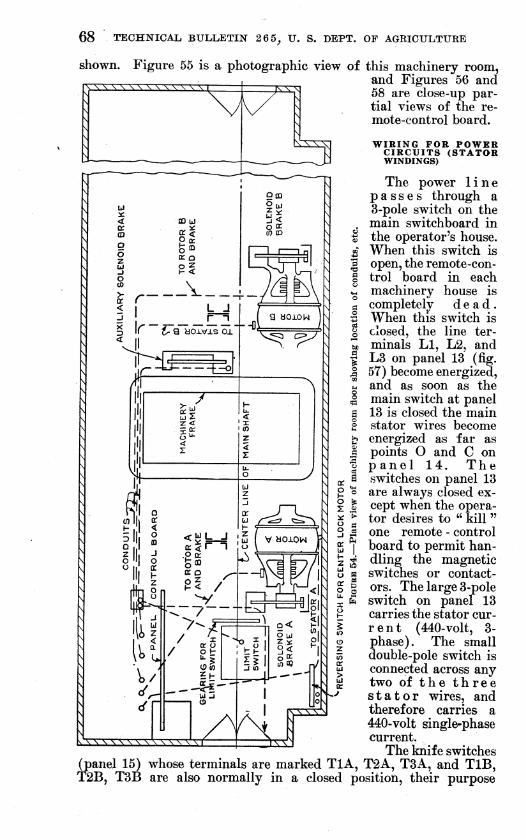
68 TECHNICAL BULLETIN 26 5^ U. S. DEPT. OF AGRICULTUBE
shown. Figure 55 is a photographic view of this machinery room, and Figures 56 and 58 are close-up par- tial views of the re- mote-control board.
WIRING FOR POWER CIRCUITS (STATOR WINDINGS)
The power line passes through a 3-pole switch on the main switchboard in the operator's house. When this switch is open, the remote-con- trol board in each machinery house is completely dead. When this switch is closed, the line ter- minals LI, L2, and L3 on panel 13 (fig. 57) become energized, and as soon as the main switch at panel 13 is closed the main stator wires become energized as far as points O and C on panel 14. The switches on panel 13 are always closed ex- cept when the opera- tor desires to " kill " one remote - control board to permit han- dling the magnetic switches or contact- ors. The large 3-pole switch on panel 13 carries the stator cur- rent (440-volt, 3- phase). The small double-pole switch is connected across any two of the three stator wires, and therefore carries a 440-volt single-phase current.
The knife switches (panel 15) whose terminals are marked TlA, T2A, T3A, and TIB, T2B, T3B are also normally in a closed position, their purpose
sssssss^

ELECTRICAL EQUIPMENT ON MOVABLE BRIDGES 69
1 ̂ 11
•/y ML /iJ-^ laA ̂ J . S¿i
IH 1
1 .^
4 r' -i-'^i^ ^Oi / M-
in
/ m ^^^^H^B^^^^^* l^^^^^^^^^^^^^^^^B
mi fr . ^. . f^- '
FiGüKE 65.—Partial view of machinery room of a double-leaf bascule bridge. The resistance grids for the rotor circuits are shown at A, the current-limit relays at B, the overload relays at C, the reversing contactors at D, the motor switches at E, the main-line switch at F, the contactor panel for the auxiliary brake at I, the contactor panel for the motor-mounted brakes at J, and the contactors for con- trolling the rotor resistance at H. The main hoisting motor. A, Is shown at K, the motor-mounted brake at L, the band brake (hand operated) at P, and the motor shaft coupling at M. The gears, G, are numbered consecutively from the main pinion Gl

70 TECHNICAL BULLETIN 2 6 5, V. S. DEPT. OF AGEICULTUEE
being to provide a means of cutting out one of the motors without interfering with the operation of the other. It will be observed that the wires from terminals TIA, T2A, and T3A lead to the stator wind- ings on motor A, while the other three lead to the stator windings on motor B.
The line wires LI and L2 run through a system of overload relays and current-limit relays and terminate at points O and C on panel 14. (These relays modify the control circuits and have no effect on the power current. Their operation will be discussed later.) The
FIGURE 56.—Upper portion, of magnetic-control board. The grid-type resistors are shown at A, the reversing contactor for the hoisting motors at B, the current-limit relays at C, and the knife switches for power and control circuits at D, E, and F. Note the mechanical interloclsing of the reversing contactor and the auxiliary contact points
third line wire runs direct to the terminals T3B and T3A, and thence to the stator windings on the main hoisting motors.
Assume that the line switches onpanel 13 and also both motor switches on panel 15 are closed. When the main power switch in the operator's house is closed, therefore, one of the three stator wires (namely, T3A and T3B) for each motor is energized.. With the reversing switch (panel 14) in the position shown, however, the other two stator wires are dead, the circuit being open at O and C.
When switch O (panel 14) is closed, however, the stator windings carry current, and the motor starts to turn over. If switch O is

Variable KO+or Kasis+anca center- lock motor
Controller for operating cen+ir lock
this push bu+fenfanci also on«» opcra+inq l-U) ara usad -ho apply current af+er -Hie limit switch has cut off ^ aarrxi. Note that this button Shor-+ orcui+S contacts Band 25.
This wheel mcves upward and à^^^°.'^'\ with the span, b< ■ ..-^ driv shaft ond shown b<alow~
with the span, being qœared to the n^ain äriyf shaft ond makas contacts as
obouti
Motor naountcd solenoid oiroai¥
Motor mowrrtcci solcnoidl circuir
~Uam tnoftor B
FIGURE 57.—Wiring diagram for double-leaf bascule bridge (only one leaf shown) «4559 ° CFaee page TO)

ELECTBICAL EQtTItMEîTT ON MOVABLE BRIDGES 71
Opened and switch C is closed the phase sequence for the stator is reversed, and the motor turns in the opposite direction. (This can be easily demonstrated by tracing out the connections.) The switch on panel 14, therefore, controls the direction of the motors. This switch is operated by the relays 19-20 and 19-21 cut in on the control circuit. If at a certain point on the master switch (fig. 57) contacts are made which close the circuit 19-20 then relay 19-20 will operate
,..:/. J I.« ^f^ #:-^
^-;4:^ *• ' 1 ,. « «
_ ' f X m . I- I '■''''r.^i!nr , ^f>
FioCBB 58.—Lower portion of magnetic-control board. The overload relays are Indi- cated at A. These can be set to open the circuit at any«current value (within the range for which the relay is designed) by adjusting the lugs B. The motor switches, power switch, and control switch are indicated at points F, D, and C, respectively. The accelerating contactors are shown at G, while contactors H and I operate circuits controlling the solenoid brakes
and switch O will close. At another point on the master switch relay circuit 19-21 is made and switch C closes. The wiring for this operation will be explained in detail subsequently.
ROTOR WINDINGS
The induced rotor currents are conveyed through slip rings to variable resistance units as shown in Figure 57.
The magnetic switches on panels 1 and 6, 2 and 7, 3 and 8, 4 and 9, 5 and 10 (operating in pairs) cut out a portion of this rotor

72 TECHNICAL BULLETIN 2 6 5^ U. S. DEPT. OF AGKICULTURE
resistance, and thus act as both starting compensators and speed controls. To be more explicit: At a certain point on the master switch in^ the operator's house, circuit 48-7 is made (see panels 1 and 6), and relays 7-48 close the main switches on panels 1 and 6. Panel 1 switch connects the terminals R2A-R3A and R4A (in delta) and thus cuts out the first step of resistance for the rotor of motor A. Panel 6 switch performs a similar function for motor B.
Panel 2 has a switch which connects R5A, E6A, and E7A, and thus cuts out another step of resistance. Panel 7 has a switch which performs the same function for motor B. Other panels perform a similar function until at panels 5 and 10 the contacts R14A, E.15A, and E16A for motor A and R14B, E15B, and R16B for motor B are connected and the motors are running as squirrel-cage motors with the rotor bars short circuited.
AUXILIARY SOIiENOID BRAKES
The normal position of the brake (no current through.solenoid) is with the shoes bearing against the brake wheel. The solenoid coil is excited by a 440-volt single-phase current taken from lines LI and L2, thus raising the core and releasing the brakes.
The brake operated from panel 11 is designed as an auxiliary brake and is entirely independent of the leai-limit switch or the master switches in the operator's house. It is controlled by the push button shown at M in Figure 57; the manner of control being as follows: The solenoid will operate when the switch on panel 11 is closed, since wire 12 goes directly back to one terminal of the line, and wire 48 directly to the other. It is only necessary, therefore, to close the switch on panel 11 and the brake will be released. The above switch is closed by means of relay coil 17-46. Wire 17 con- nects to one terminal of the line through 16 to 48. It is only neces- sary, therefore, to connect wire 46 to the other terminal (12) and the switch at once operates. The push-button station shown at M accomplishes this result as follows: There are two push buttons in this station, one labeled "stop " and other labeled "start." These buttons are of the spring t;ype .aijd are normally held in the position shown at M, in which position the switch at panel 11 is open. Now if the start button is pressed contact 46-47 is made, and relay circuit 17-46 on panel 11 is completed through 46-47-12 and from 12 back through the cable to the terminal point 12 on panel 13. Instantlv relay 17-46 operates, attracts its armature and closes the main switch on panel 11, making the contacts 12-34 and 48-33 and the auxiliary solenoid brake is released.
It may appear that as soon as the operator's finger is removed from the start push button the circuit will open and the brake will be again applied. This is not true, however, owing to the following device : There is an auxiliary contact 46-47 operating on the relay that closes the main switch at panel 11. The instant that contact 46-47 is made at the push button station, contact 46-47 is made on panel 11. Release of the start push button does not release the con- tact 46-47 on panel 11, and the brakes continue to be released. This device, known as a holding relay circuit and described on page 29, is a rather common expedient in magnet-control wiring of this kind. If the stop push button is pushed down, contact 47-12 is broken and

ELECTRICAL EQUIPMENT 0Î3" MOVABLE BRIDGES 73
both 46 and 47 are instantly killed, rendering panel 11 dead until the start button is again pushed down.
Thus at any position of the leaf and at any time, regardless of the position of limit switch, master switch, controller, or center lock, if the start button is depressed the auxiliary brake is instantly re- leased ; if the stop button is depressed the brake is applied.
During the installation of this device on this particular job it was argued by some of the engineers connected with the work that a serious defect lay in the fact that the operator did not know from the position of the push buttons whether the emergency brake was on or off. As a matter of fact this is unimportant. At any position, regardless of whether the brakes are on or off, the start push button will instantly release them or keep them released if they are already released, and the stop button will apply them or keep them applied if they are already on.
MOTOR-MOUNTED SOLENOm BRAKES OR PRIMARY BRAKES
These brakes are mounted on the motor shaft, whereas the auxiliary or emergency solenoid brake is mounted on an intermediate shaft. There are two motor-mounted solenoid brakes and one auxiliary solenoid brake for each leaf.
The motor-mounted brakes operate on circuit 12-48, as shown on panel 12, but are controlled through a relay 4-19 wired through the master switch. It will be shown later that point 4 on this relay is energized on point 1 of the master switch, the other terminal de- pending for its connection to the line on a second auxiliary switch 19~17 on the panel 11 marked "Aux. sw. B." In other words, before the primary brakes can be released the master switch must be moved to point 1, but in addition the start push button must be pressed to make contact 17-19 on panel 11.
START AND STOP PUSH BUTTONS
It was shown above that there can be no connection between wire 19 and the power main until the start push button is pressed, which means that this button must be pressed before the primary brakes can be released. From inspection of panel 14, it is also seen that until this start button is pressed there can be no current through relays 19-20 or 19-21, and consequently the reversing switch can not be closed in either direction, nor the motors started.
The operator must first press the start button, else he can not re- lease the brakes nor start the motors. This start button is, therefore, a key to the entire operation. For heavy traffic, or where other con- ditions warrant special precautions against premature opening, it may be advisable to interlock this start control with all roadway gates and signals. This would require some modification of the wiring shown in Figure 57 and was not considered necessary in this case.
INTERLOCK WITH CENTER-LOCKING MECHANISM
Inspection of Figure 57 shows that one terminal of every control relay on the board is connected in some way (or may be connected) with wire 48, which is one terminal of the control circuit. For ex-

74 TECHNICAL BULLETIIT 2 6 5^ U. S. DEPT. OF AGRICULTURE
ample, relay 4-19 on panel 12 leads through the contact 19-17 on panel 11, through 17-16 and 16-48 on the overload relays directly to the line. (Under normal conditions these contacts are all closed.) The other terminals of all these relays lead through the master switch.
In order that the master switch may close the various control cir- cuits, there must be some way of leading the current from the other side of the line (wire 12) to this master switch. This is done through contact 12-3 on the center-locking device. When the center-lock bar is driven, locking the leaves together, contact 12-3 is open and the master switch is entirely dead. It is impossible to release the motor- mounted brakes or to start the motor. When the bar is drawn, con- tact 12-3 is made and points 3 and 2 on the master switch are ener- gized. This interlock insures the withdrawal of locking bar, release of brakes, and starting of main lifting motors in proper sequence.
MASTER SWITCHES
The distinction between master switches and manual controllers is that the former carry light control currents while the latter carry main-power currents. The main-control board in this case is operated through a master switch, while the center-lock motor is operated through a controller« (carrying 440-volt, 3-phase current).
As the handle on the master switch is moved around, the finger contacts, 1, 2, 3 . . . 10 fall on the vertical lines, 1, 2, 3, etc., making the following contacts:
FOBWABD OB OPENING
Point Electrical energy on— 0 Wires 2 and 3. 1 Wires 2, 3, and 4. 2 Wires 1, 2, 3, and 4. 3 Wires 1, 2, 3, 4, 6, and 7. 4 Wires 1, 2, 3, 4, 6, 7, and 8. 5 Wires 1, 2, 3, 4, 6, 7, 8, and 9. 6 Wires 1,2,3,4,6,7,8, 9, and 10.
BEVEBSE OB CLOSING
, 1 Wires 2, 3, and 4. 2 Wires 2, 3, 4, and 5. 3 _ Wires 2, 3, 4, 5, 6, and 7. 4 Wires 2, 3, 4, 5, 6, 7, and 8. 5 Wires 2, 3, 4, 5, 6, 7, 8, and 9. 6 Wires 2,3,4, 5, 6, 7, 8, 9, and 10.
Assume the span closed, and the master-switch handle at neutral. Assume the start-push button to have been pressed so that the auxiliary brake is released, and contact 17-19 on panel 11 is made.
As the master-switch handle is moved to point 1, wire 4 is ener- gized, relay circuit 4r-19* on panel 12 is made, and the motor-mounted brake released.
« The term " controller " where used throughout this discussion has been employed to designate a manual controller and should be so understood. As a matter of strict terminology a controller is any device for controlling an electrical mechanism, and there- fore includes the entire control assembly. It has not been used in this sense at any point in this discussion, however, but rather to designate certain particular types of manually operated switches,

ELECTRICAL. EQUIPMENT ON MOVABLE BRIDGES 75
On point 2 of the master switch, energy is applied to wire 1 which runs to the limit switch. This limit switch (geared to one of the operating shafts and set so as to open and close contacts 1-11 and 5-25) will be described in detail later. On its last trip down this limit switch has closed contact 1-11 so that current from wire 1 flows through wire 11 to panel 14, from 11 to 20, and thence through the relay 20-19, thus closing the reversing switch O and causing current to flow in the stator windings. The motors, therefore, start up with all rotor resistance in. At panel 14 an auxiliary contact connects wire 6 with the line so that finger 6 on the master switch is now energized. On the next point on the master-switch .contact 6-7 is made. This completes circuit 7-48 and closes the accelerating
. contactors on panels 1 and 6, cutting out the first step of rotor resistance, and speeding up the motor. The other successive points on the master-switch cut out successive resistance steps in the rotor circuit increasing the motor speed.
When the span is from 10° to 15° from its fully open position the leaf-limit switch opens contact 1-11 and the reversing switch flies open deenergizing the motor.
LIMIT SWITCHES
Figure 44 on page 55 illustrates the general arrangement of a limit switch similar to the one used in this case except that two traveling wheels are shown in the figure while only one is used on the bridge described. Ordinarily the limit switch should be placed as near the main trunnion as possible to avoid variation in timing due to backlash on the power gears. This main trunnion, however, is a very slow moving shaft, and a large number of back gears would be necessary. The back gears, when used, should be made of hard- ened and heat-treated metal and should be polished to reduce back- lash (by running each gear with its mate using an abrasive).
Sometimes the limit switch is arranged to turn through an angle equal to the opening angle of the leaf without any speed increase. In other words, the limit switch ,is simply a master switch set on its side with its shaft keyed to the main trunnion. As the trunnion moves through the opening angle, the master-switch shaft moves through the same angle and makes and breaks the desired contacts. This design eliminates the necessity for a large number of back gears, but introduces a sliding electrical contact with the consequent danger of sparking and smoking. A switch of this type, but with one set of gears to increase the angle of rotation of the contactor shaft, is shown in Figure 45.
Figure 57 shows that as the bridge is started upward from the closed position the moving contactor wheel on the leaf limit switch moves toward the t^p of the drawing.
The pilot light indicating bridge closed is glowing, but all other lights are out ; contact 1-11 is closed (having been closed on the last downward trip of the limit switch, but contact 5-25 is open, having been opened just before the bridge was closed on the last trip).
As the limit-switch contactor wheel W travels upward, its first function is to trip the switch closing the circuit 52-56, thus causing the lamp indicating nearly closed or 10° open^ 15° open, etc. (as may be desired), to glow,

76 TECHNICAL BULLETIN 2 6 5, U. S. DEPT. OF AGRICULTURE
Its next function is to close contact 5-25. This contact controls the reverse or downward motion of the leaf (see master-switch wir- ing) 5 and was, of course, opened at this same point on the last trip down. It must be closed at this point, else the operator would not be able to lower the bridge on the next trip.
The third function of the limit switch is to open contact 1-11, cutting off power from wire 11 on control panel 14, and causing the reversing switch at O to fly open, thus cutting off current to the motors. At a certain point on the travel of this contactor wheel the nearly-open or 60°-open light circuit is closed, and at the end of travel the bridge-open light is also made to glow.
On the return or downward trip, contact 1-11 is remade, the lights are extinguished one by one, and at a predetermined position near the end of the return, contact 5-25 is opened, thus opening the reversing switch C on control panel 14 which, in turn, cuts off current irom the hoisting motors.
The limit switch also applies the brakes (motor-mounted) at certain predetermined points. This may be accomplished in a number of ways, and is not shown in Figure 57.
The small pilot lights indicating the position of the bridge may be of different colors if desired. These lights are located on the operating board. If desired, other positions of the leaf may be indicated by introducing additional contacts on the limit switch.
Current may be applied to the motors after the limit switches have operated by means of the short-circuiting push buttons shown in the diagram.
OVERLOAD RELAYS
Referring to panel 17 on the remote-control board, it will be seen that if the stator current rises to a certain predetermined value the solenoid cores will be drawn up, opening contacts 48-16, or 16-17. This breaks the circuit through relay 46-17 on panel 11, and at the same time breaks auxiliary contacts 46-47 and 17-19, thus opening the reversing switch and putting on all solenoid brakes.
The opening of contact 48-16 or 16-17 on the overload relay is only momentary, inasmuch as the rising solenoid core also closed the contact 51-48 or 18-16, and relays 2-51 or 2-18 at once remade the circuits 48-16 or 16-17. This arrangement is quite common in industrial wiring, and is known as an automatic-electrical reset which has been described.
This momentary break in the circuit, however, is sufficient to open contact 46-47 on panel 11, so that the entire control board remains dead until the start push button is again pressed.
The purpose of these overload relays is to prevent the possibility of a destructively high current flowing through the stator coils due to an excessive load on the leaf, or for other reasons.
CURRENT-LIMIT RELAYS
In order to prevent the operator from cutting out the various steps of rotor resistance too rapidly and inducing high motor cur- rent and a low power factor, there is provided a system of auxiliary

ELECTRICAL EQUIPMEISTT OK MOVABLE BRIDGES 77
contacts with wiring leading through a system of current-limit relays.
The rotor resistance for motor A is varied by means of the jacks or magnetic accelerating contactors on panels 1, 2, 3, 4, and 5. Mo- tor B is operated through contactors 6, 7, 8, 9, and 10 in exactly the same manner. Therefore, for the purpose of illustration, motor A may be considered alone.
Consider the contactor on panel 1 open, and the motor running with all resistance in. At the instant this contactor is closed, the rotor currents increase (due to the decrease in rotor resistance) and the motor speeds up. The stator currents also increase to overcome the demagnetizing tendency of the rotor currents.
At the instant the main contactor on panel 1 was closed (or slightly later, depending upon the adjustment of the contacts) the auxiliary contact 23-24 was made, but the increased stator current has opened contact 50-48 on the current limit relay (panel 18) and very little current flows through wire 24 (since the resistance of the relay 48-24 is very high).
The 22 side of relay 22-8 on panel 2 is, therefore, practically dead, *and even if the master switch were moved to the next point (energizing point 8 from the other side of the line) insufficient current would flow through relay 8-22 to close the jack.
As the motor speeds up, however, the stator current drops until the core of the current-limit coil is pulled down by the balance relay, making contact 50-48. This contact shunts the current in wire 24 around the high resistance of relay 24r^8 (panel 18) and instantly point 22 on panel 2 is energized.
Then, and not until then, can this switch be closed by energizing point 8 through the master switch. Contact 48-22 on panel 2 is made and contact 23-22 is broken with the closing of the contactor on panel 2 so that this contactor is held in the closed position there- after by means of the circuit 42-22-8 and further operation on this panel is independent of the stator current. If this were not pro- vided for, any further current increase would cause this contactor to fly open which is obviously not the purpose of these current-limit relays.
In a similar manner, contact 30-29 on panel 2 energizes one side of the relay on panel 3 as soon as contact 48-49 on the current-limit relay drops in place, and so on for each of the five magnetic accelerat- ing contactors.
This arrangement insures a proper time sequence in closing the contactors, and eliminates the possibility of cutting out any resist- ance step before the motor has attained its proper speed. Were it not for this arrangement, a careless operator might frequently cut out resistance with such rapidity as to operate the overload relays, killing the entire board, and resulting in a jerking and uneven move- ment of the leaf. The life of a bascule span depends to a great extent on the elimination of such unnecessary jars and shocks.
It will be observed that the last two jacks operate from one point on the controller, the time sequence of closing (for panels 4 and 5) being entirely controlled by contact 30-37 (panel 4) and the current-

78 TECHNICAL, BtJLLÊl:,IN â6 5^ U. B. ÎMPT. ÔF AGJRlOTJLTtTRîî
limit relay. This arrangement is termed a time-element switch, or contactor.
CENTER-LOCK MOTOR CONTROL
Figure 57 illustrates the general arrangement of limit switch, re- sistance elements, reversing switches, etc., for the center-lock control which involves no new features and does not require detailed discussion.
Since the load is light, the variable rotor resistance might very well be omitted, using a squirrel-cage motor. The saving in cost, how- ever, would be verj^ small.
The power circuits in this case are taken through the contactor which is a manual controller rather than a master switch.
GENERAL REMARKS
Figure 57 is typical of working drawings prepared by manufactur- ers except that considerable explanatory matter has been added.
The engineer in charge of the erection of a bascule span must be able to check a wiring diagram of this kind, and to trace out the various circuits and their functions, else he can not possibly give the work the intelligent supervision it deserves.
The wiring diagram of Figure 57 is only one of many possible arrangements, but a careful study of the drawing and explanatory matter will give the engineer an understanding of the subject suffi- cient to enable him to prepare an intelligent preliminary sketch and to cooperate with the electrical contractor in working out the most efficient and economical arrangement for the particular problem before them.
No attempt has been made to describe the interlocking for road- way gates and signals employed for this particular bridge as the general principles involved have already been discussed and an example of gate and traffic-barrier interlocks is discussed on page 83.
CONTROL SYSTEM FOR A RIM-BEARING SWING SPAN USING ALTERNATING CURRENT
The wiring and control assembly for the double-leaf bascule just described may be termed a fairly complex installation, although it is not as complicated as that for many of the larger bascule struc- tures. The installation which is now to be considered has been selected as representative of a much simplier type of control.
Figure 59 shows the general layout of the wiring for this struc- ture which is a rim-bearing swing span, 235 feet in over-all length. The traffic over this structure and the openings required were not sufficient to warrant the installation of power gates or traffic barriers, and no attempt was made to interlock traffic lights, sirens, and other signals with the span movement.
Electric power is delivered at a small power house built on the bank of the stream, and the main switchboard is a very simple affair, as it need only provide space for a power meter, and the line switches for power and lighting circuits.
The power line supplies 3-phase, 220-volt, alternating current and is run to the center of pivot pier through a submarine cable termi-

25W-RED AND GREEN 25 W-RED AND GREEN ON SPAN AT CENTER OF SPAN
25 W-RED AND GREEN
ALL LIGHT CIRCUIT WIRES N912 STRANDED IN JINCH CONDUIT ON SPAN
METER AND SWITCH BOX IN OPERATING HOUSE
25W-RED0N 2 OUTLETS BELOW END PIER
GATE ARM i CENFLK =» PIER '
TO TRANSFORMERS FURNISHED AND INSTALLED BY POWER CO.
POWER CIRCUIT 3* 22aV 20-H P ~^ >
SUBMARINE CABLE.-
3-feOAMP 3-POLE SINGLE THROW INCLOSED SAFETY SWITCHES WITH REFILLABLE FUSES
2-INCLOSED. REVERSING MAGNETIC SWITCHES WITH TEMPERATURE RELAY COMPLETE FOR 7.5 HP END-LIFT MOTORS. i
l-INCLOSED MAGNETIC SWITCH WITH TEMPERA- i TURE RELAY COMPLETE FOR 15-HP TURNING MOTOR i
DUPLICATE EQUIPMENT.SAME \ SWITCH B OPEN z;^ AS OTHER END CONSISTING ONLY WHEN (O) OF I MOTOR AND2 LIMIT SWITCHES WEDGES ARE FULLY RELEASED rg-
zir'
r'Ú k2^3.,
'Z S' A3A
SWITCH C CLOSED ONLY WHEN WEDGES ARE FULLY RELEASED
SPAN MOVEMENT MAY BE INTERLOCKED WITH ROAD- WAY GATES OR TRAFFIC BARRIERS OR SIGNALS BY' CUTTING INTO THIS CIRCUIT THROUGH SUBMARINE CABLE
END-WEDGE MOVEMENT MAY BE INTERLOCKED WITH ROAD- WAY GATES. BARRIERS OR _ SIGNALS BY CUTTING CIRCUIT AS INDICATED FOR ONE OR MORE INTERLOCK. RUNS THROUGH SUBMARINE CABLE
SWITCH A OPEN ONLY WHEN f-ZZZI WEDGES ARE FULLY DRIVEN |, rTr-H"! -^------Z-lj f" PUSH ~"
►*~ZZZZr~'L~~11.~!j BUTTONS *~ "" DRIVE-^ I-REVERSING DRUM SWITCH RELEASE- FOR SLIP-RING INDUCTION STOP- MOTOR FOR PRIMARY AND SECONDARY CONTROL WITH AUXILIARY CONTACTS- FOR USE WITH PRIMARY MAG SWITCH
I-SPEED REGULATING DUTY RESISTOR, REVERSING EQUIPMENT.(EPC RESISTOR- CLASSIFICATION N^ 95)
I-220V 3*I5+^.P BALL-BEARING SLIP-RING INDUCTION MOTOR.FOR VERTICAL OPER-. ATION OF MOTOR WITH PINION MOUNTED ON TOP END OF MOTOR SHAFT
M
2-CONDUCTOR N?8 STRANDED SUBMARINE CABLE FOR NAVIGATION. BRIDGE AND GATE LIGHT CIRCUIT-750-V MAXIMUM PRESSURE
I-220-V-60-AMP SINGLE-THROW DISCON-' NECTING.KNIFE SWITCH.3-POLE.FUSED AT BOTTOM. WITH REFILLABLE FUSES, SLATE BASE 1-IIOV-30-AMP SINGLE-THROW DISCON- NECTING.KNIFE SWITCH. 2-POLE WITH REFILLABLE FUSES.SLATE BASE
N'G-BANOS GAGE-STRANDED WIRES-R C-DOUBLE BRAID-50-AMP feOO-V -POWER WIRES TO END MOTORS
V
LIGHT CIRCUIT »N OPERATORS HOUSE N? 12 STRANDED ÏH j INCH CONDUIT
2-II0A/-30-AMP SINGLE-THROW,FR0NT CONNECTED KNIFE SWITCHES FUSED AT BOTTOM-SLATE BASE PLAIN FINISH,
_ 2-POLES EACH. WITH REFILLABLE FUSES
1-220-3v>-7 5-H P 900-R PM HIGH TORQUE SQUIRREL-CAGE INDUC- TION MOTOR FOR END LIFT
llsAA^
|-L)MtT SWITCH "FOR DRIVE AND RELEASE CON- BlTROLOFENO
2'#VUFT2CiRCUlT
N52BANPS-RC STRANDED WIRES DOUBLE BRAID-90AMR 600 VOLTS.
^CONTROLWIRES N« 14 BANOS-RC SINGLE BRAID-5TRANDE0-I5AMP600VOLTS. I-LIMIT SWITCH FOR DRIVE AND RELEASE CONTROL OF END LIFT-l-CIRCUlT-
, SEQUENCE OF OPERATIONS 1 CLOSE POWER AND SIREN SWITCH IN OPERATOR'S HOUSE DRIVEN AND RELEASED BY THE STOP BUTTON WEDGE 2 CLOSE BOTH GATES MANUALLY(5WITCH ON GATE ARM TURNS SWITCH A CLOSES AT BEGINNING OF TRAVEL;B CL05ED,C OPEN;
o S ON RED LIGHT WHEN GATE IS CLOSED;0FF WHEN OPEN) B-OPENS AT END OF STROKE. C CLOSES AT END OF STROKE i o 3ST0P SIREN 6.TURN CONTROLLER HANDLE AND SWING BRIDGE OPEN.RE" cc d / D,.,. I ATr Lj DIM M AMI .M . V AMH uAi HI iMTii RPinr F RFC IN^ LEASE LATCH PIN. BRIDGE MAY BE STOPPED ANYWHERE BY Í7i^4PULLLATCH PIN MANUALLY AND HOLD UNTILBRID&tbLblNi» u»K,rvDnM/r unrnrc ciA/irru * n nc^cn o noFw r rinqpn dg TOSWINGOPEN 15-H P CENTER-SWING MOTOR IS DEAD AS HANDBRAKE.WEDGESWITCHACLOSEDB OPEN C CLOSED § ? INTERLOCK SWITCH C IS OPEN UNTIL END WEDGES ARE 7.TURN CONTROL^HANDLEJN 0PTO^SJ_TEJ)1^RECT10N a^^^
FULLY RELEASED. WEDGE SWITCH A OPEN.B CLOSED.C OPEN.
"-^^■^E^ND^O^^t^^^^^^^^^^^^^^ OPENS AND CLOSES INTERLOCK SWITCH C. MECHANICALLY TO LOCKED POSITION. AT THE BEGINNING OF THIS STROKE CONNECTED WITH 8,THEREBY GIVING POWER TO SWING LIMIT SWITCH B CLOSES.THEREBY OPENING INTERLOCK MOTOR THROUGH CLIMIT SWITCH A CLOSED AT BEGINNING OF SWITCH C KILLING SWING MOTOR. AT THE END OF THIS RELEASE STROKE TRAVELOFTHE END WEDGES MAY BE STROKE LIMIT SWITCH A OPENS. STOPPED AT ANY INTERMEDIATE POSITION BETWEEN 9.0PEN GATES MANUALLY, OPEN POWER SliNlTCH IN OP'RS HOUSE
o V2 c
BRIDGE LATCH PIN SNAPS IN AUTOMATICALLY WHEN BRIDGE IS CLOSED. WEDGE SWITCH A CLOSED, B OPEN.C CLOSED
FIGURE 59.—Wiring diagram for rim-bearing swing span
o
S o >
d
fei
O
O
> td
t3d
5 Q
^ O

80 TECHNICAL BULLETIN 265, U. S. DEPT. OF AGRICULTURE
nating in three single-throw, 3-pole, inclosed safety switches, pro- tected with refillable fuses. These three safety switches feed three magnetic contactors, one for each of the end wedges, and one for the swinging or turning motor. The wedge contactors are of the reversing type, with a temperature overload relay wired as an integral part, and are operated by a push button, and a drum-type controller is provided for the swinging motor. The wedge motors are direct line connected and of the squirrel-cage induction type, and the turning motor is of the slip-ring induction type, with the rotor resistance wired to cut out in successive steps on the controller. No current-limit relays are provided, as the installation is small and each magnet contactor is protected with a temperature relay. The swinging-gear and wedge-motor circuits are suitably interlocked as indicated at A, B, and C. The entire control assembly is mounted at the side of the roadway in the plane of the trusses in a weather- proof metal cabinet which is kept locked except during operation. The operator goes to the center of the span, unlocks the control cabi- net, and completes the entire operating cycle at one station in full view of both roadway and waterway.
The detailed arrangement of wiring is evident from Figure 59. However, a few explanatory paragraphs may be helpful in under- standing the workings of the installation. The operating sequence is completely given in Figure 59. The detailed wiring, however, may need some explanation.
CONTROL WIRING
When the three safety switches are closed, each end-wedge circuit is energized as follows, L2-8-11-9-7-2 , etc., down to point 4 on the release push button on one side of the line, and L3-^5-6-6 on the other side of the line. When the release button is operated, con- tact 4^6 is made, and the wedge-motor circuit is closed in the release direction. This is accomplished by the attraction of operating relay 2-7, which also closes auxiliary contact 4-10, which shunts 4-10-6 around the release push button, so that the wedge motors continue to operate after the push button is released.
The control circuit will be opened and, therefore, the wedge motors will be inoperative under the following conditions :
(1) When the wedges have been fuUy released. This is accom- plished by means of the limit switches B (one at either end wedge) by means of which the control circuit is opened at either one or both of the contacts 2A-2.
(2) When the stop push button is pressed. This opens contact 5-6, opens relay 2-7, and therefore opens contact 4-10. A reestab- lishment of contact 5-6 on the stop button (by releasing the button) will not remake the control circuit, as it is now broken at auxiliary contact 4^10, and can only be remade through the release button. The stop button, therefore, stops the mechanism at any point permanently.
(3) When the drive button is operated. This breaks contact 2-4 and opens the control circuit. It is seen that the push-button in- stallation furnishes an effective reversing interlock.
(4) When the temperature relay opens the control circuit at con- tact 8-11. This furnishes overload protection to the wedge motors.

g Ül
i i
3-POLE OIL-TYPE SWITCH AND CIRCUIT BREAKER WITH INVERSE TIME LIMIT
vOVERiOAO TRIP AND LOW-VOLTAGE RELEASE
440 VOLTS 3-PHASE-
Ï
% ill i! i! WATTIIEFER
AMMETER VOLTMETER
DOOR-TYPE SWITCH AT BARRIER.CLOSED ONLY WHEN BARRIER
IS CLEAR
CLOSED (fÏÏuSWHËN" JACKS ARETpTENED./.,
AN0(ÄFWH!N *~^^ RELEASED
DOOR-TYPE SWITCH AT BARRIER. CLOSED ONLY WHEN BARRIER OPPOSES TRAFFIC. SHORT-CIRCUIT PUSH BUTTON ON OPERATOFfS BOARD.
REVERSING SWITCH ON OPERATORS BOARD. CLOSEDaEHL , ^ TO RELEASE JACKTAND i \2 <
SHORT-CIRCUIT PUSH BUTTON CñWrO TIGHTEN THEM 5
Ê ^
■• 'uiS . BUTTON FOR BARRIER,^, '
0^ :::jir SHORT CIRCUIT PUSH
'aai:
OVERLOAD CURRENT-LIMIT RELAY RELAY WIRING NOT SHOWN
AISE,*f>f LOWER tftf
^»dj^^Ç Ä^
TIME ELEMENT SEQUENCE SWITCHES
TO ROTOR OF MOTOR 8
DOOR-TYPE SWITCHES AT GATES. aOSED ONLY WHEN GATES ARE DOWN
> DOOR-TYPE SWITCH AT JACKS. CLOSED ONLY I WHEN JACKS ARE FULLY TIGHTENED
2^T~-~-SOLENOID-OPERATED VALVE TO CLEAR BARRIER
SOLENOID OPERATED VALVE TO RAISE BARRIER AGAINST TRAFFIC
THE FIRST THREE ACCELERATING CONTACTORS FOR EACH MOTOR ARE TO BE WIRED THROUGH
THE CURRENT LIMIT RELAY
TO MOTOR-MOUNTED BRAKE
FIGURE 60.—^Typical circuits for electrical control and interlocking 100-foot single-leaf bascule span
I Q
S
d
fe!
o
o
Ö O tel
OO

82 TECHNICAL BXJLLETIÎsr 26 5, U. S. MPT. OF AGRlCtTLTTJKE
On the return trip the wedge motor is actuated by the control circuit energizing operating relay 3-9 and the circuit is completed at 1-6 (the drive button), and the shunt contact 1-6 on the contactor panel. This circuit may be opened at either of the limit switches A (contacts 3-3A), the release button (contact 1-3), the stop button (contact 5-6), or the temperature relay. The same interlocks are therefore furnished for the drive direction of the wedge motors as :are furnished in the release direction.
The magnetic panel controlling the swinging-gear motor is not of the reversing type, and reversing, acceleration, and starting com- pensation are controlled by the drum-type controller. The first point on this controller in either direction closes the control circuit operating the line contactor relay 2-4. This control circuit is wired through contact switch C on the end wedges, thus rendering it im- possible to put power to the swinging gear until both end wedges are fully released. The dotted lines indicate a method of interlock- ing roadway gates, barriers, and signals should traffic conditions demand such a precaution at a future time.
The connection of circuits between fixed and moving portions of the structure is through a spiral length of flexible submarine cable supported on a flat platform attached to the pivot pier above the masonry and below the level of the roadway deck. There is enough slack in this cable to permit the span to be turned through 180° in either direction, the coil merely adjusting itself to the position by slipping over the platform. This arrangement eliminates the neces- sity for sliding contacts, which are often a source of trouble due to sparking and flashing, especially if they are so located as to be exposed to grease or dust.
CONTROL SYSTEM FOR A SINGLE-LEAF BASCULE BRIDGE USING ALTERNATING CURRENT
Figure 57 is typical of drawings submitted by manufacturers or electrical contractors as shop or working drawings. Figure 60 is the type of drawing which should be prepared by the engineer for use by bidders, and shows the general layout and arrangement of circuits. This figure does not indicate detailed wiring but only the general character and arrangements of circuits.
The general plan of control and interlocking used on this job was very much the same as that for the double-leaf bascule described on pages 66 to 78.
INCOMING LINES AND SERVICE CIRCUITS
The incoming lines go directly to the main switchboard in the operator's house. Lighting and heating circuits are taken from the power company's transformer direct to the switchboard and pass through ordinary knife switches, protected by cartridge fuses. The power circuit is passed through a 3-pole, oil-type switch with inverse time element overload relay, and suitable low-voltage protection. The various heating and lighting circuits and the location of all metering devices is indicated in Figure 60.

ELECTRICAL, EQUIPMENT OK MOVABLE BEÏDGES 83
MAIN CONTROL CIRCUIT
This circuit is taken from two of the main power leads through a knife switch mounted on the remote-control board as shown at A. This control circuit branches at point B, runs through the overload relay contacts at C (which are, of course, normally closed) through the stop button, through the start button, through the master-switch reset (contact 10-11), and back to the line through the gate, rear-jack, and traffic-barrier interlocks.
To close this control circuit it is necessary to set the master switch on either neutral or point 1 or 2 either way, to close both roadway gates, to set the traffic barrier, and to release the rear jacks. The control circuit may then be completed through the start button, which actuates operating relay D, closing contacts E and F, and re- leasing the auxiliary solenoid brakes. Contact E shorts around the start button and the master-switch reset, allowing the start button to be released and the master switch to be freely operated. Contact F energizes one side of the magnetic reversing contactors at points 26 and 27.
If either of the roadway gates be raised or if the traffic barrier be cleared, or if the rear jacks be moved from their fully released position, or if an overload current opens contact C, the main control circuit is broken, operating relay D is deenergized, opening contacts F and E, and applying the auxiliary solenoid brakes. The gates, barriers, and rear jack must be reset by hand. The overload relay, however, is of the automatic electrical reset type and reestablishes the control circuit through contact G, relay K, and contact I an instant after it is broken at C.
Howevel*, the momentary interruption of the current has opened contact E, and after the gates, barriers, and jacks have been set, it is still necessary to reset the master switch and to push the start button.
Thé stop button breaks the control circuit and applies the auxiliary solenoid brakes at any point in the operating cycle and stops all span movement. Before the span may be continued in operation the master switch must be reset and the start button operated.
The master-switch reset in combination with the start button is complete " no voltage " protection for the entire mechanism. Should the power be discontinued at any time during the operating cycle, contact E is opened and it is impossible to operate the span from a point of rest on any power notch of the master switch above point 2 (the first power point). If this were not done (if contact 10-^11 were cut out of the control circuit) it would be possible to push the start button and start the lifting motors from a point of rest and with so much of the rotor resistance cut out as to quickly kill the circuit at the overload relay, resulting in a jerky movement of the span.
ROADWAY GATES
A complete operatiiig cycle will now be considered step by step. The first operation is obviously that of sounding the siren and traffic gong. This operation could very well be interlocked with the roadway gates but it was not thought to be necessary in this case.

84 TECHNICAL BULLETIN 2 6 5, V. S. DEPT; OF AGEICULTtlEE
The roadway gates are then closed by throwing two double-throw, inclosed safety switches on the operator's bench. The ordinary standard arm gates equipped with their own motors were used. Gate motors are generally equipped with limit switches which cut off power to the motor at both upper and lower limits of travel. The motors are small enough to be connected directly to the line and the gates can be operated by a simple double-throw reversing switch as shown. It will be observed that the gate-motor circuit runs through a door-type switch on the barrier which is closed only when the barrier is clear to traffic, so that after the barrier is once set against traffic the gates can not be moved under power.
FioüEB 61.—A rigid type barrier of the bascule type
TRAFFIC BARRIER
The next operation is setting the barrier against traffic. The barrier is a rigid frame of the bascule type, located in the roadway of the fixed approach at the outer end of the main leaf as shown in Figure 61. It is operated by a hydraulic hoist which is actuated by two solenoid valves, one valve being used to raise the barrier, and the other to lower it. These valves are controlled by a simple reversing-type inclosed switch as indicated in Figure 60. The barrier valve circuits are interlocked with both gates and rear jacks.
REAR JACKS
Setting the gates and barriers to oppose traffic resulted in opening the gate circuit at M and closed a door-type switch N in the rear jack control circuit on the release side. Up until this time the con- trol circuit for the rear jacks has been dead on this side of the line, thus eliminating the possibility of traffic over an unlocked span.

ELECTRICAL EQUIPMENT ON MOVABLE BRIDGES 85
The rear jacks are now released by means of a simple reversing switch on the operator's board which operates a mechanically in- terlocked magnetic reversing contactor O. As the rear jacks reach the end of their travel a limit switch cuts off power to the magnetic reversing contactor and resets the connections for reverse movement. It will be observed that the instant the jacks start to release, the barrier-control circuit is opened, locking the barrier against traffic.
OPERATION OF SPAN
All safety devices now oppose traffic and the main-leaf control circuit is open at only the start button. The master switch is at neutral. The start button is pressed, releasing the auxiliary sole- noid brakes and energizing the main-leaf reversing contactors on one side of each of the operating relays 26 and 27.
The master switch is now moved to point 1 on the raise side, making the contact 6-20 and 20-25 through the leaf limit switch, thus completing the control circuit for the motor-mounted solenoid brakes, and releasing them. Point 2 on the master switch makes contact &-22 and this contact in conjunction with contact 22-26 on the limit switch closes operating relay 26 on the reversing contactor and puts power to the motor. Successive points on the master switch make the contacts &-30, &-40, and 6-50 which energize the operating relays on the magnetic accelerating contactors, thus cutting out successive steps of rotor resistance and speeding up the motor.
The last resistance step is wired to cut out automatically as soon (after contact 50 has been made) as the stator currents drop to a certain value. This arrangement is termed a time-element resist- ance step and results in five speed ranges with only four master- switch control points.
As the span moves up the leaf-limit switch moves as indicated, first breaking the jack-control circuit and at the upper limit of travel breaks contact 22-26, cutting off power to the motors, and then breaks contact 20-25 and applies the motor-mounted brakes. The interval between the breaking of these two contacts may be varied to produce a suitable drift period.
The short-circuiting buttons for the leaf-limit switch permit oper- ation beyond the upper and lower limits of travel, and the interlock short-circuits permit operation in case any device or mechanism is inoperative.
It will be noted that the motor-mounted brakes are wired in series with contact F, which makes these brakes operative whenever relay D is open. The stop button, the overload relay, or any of the inter- locks in the leaf-control circuit, therefore, set all three of the brakes.
Fig^ure 60 makes clear the operation on the return trip as well as the wiring for indicator and service lights.
CONTROL SYSTEM FOR A VERTICAL-LIFT SPAN USING DIRECT CURRENT
The three examples which have been given are all alternating- current assemblies. Direct-current control involves no new princi- ples, and, in fact, is much the same except for the method of speed regulation.

86 TECHNICAL BULLETIN^ 26 5^ U. S. DEPT. OF AGRICULTURE
Figure 62 illustrates a method of magnetic control for a direct- current lifting motor and solenoid brake recommended by one of the larger electrical manufacturing companies. The neutral or off posi- tion of the master switch opens the motor circuit and applies the solenoid brakes with all reversing contactors open. The third point on the master switch is a drift point, the brakes being released but no power applied to the motor. The fourth point closes the reversing switch with contactors A to F, inclusive, open, thus cutting the entire resistance into the series field circuit and opening the armature shunt. The fifth point closes contactor F, cutting out one step of
r-5>iLKlt.ö FItLD rARMATURE SU
\ r-SHUNTFIELDy \ F
\\ nn nn nn nn à 4r«M^V^'
ARMATURE SHUNT
REVERSING CONTACTORS
- ACCELERATING CONTACTORS
FiGUBE 62.—^Typical magnetic control for compound-wound direct-current motor and brake
resistance in the series field, and each succeeding point cuts out an additional resistance step until the motor is running at full accelera- tion with all resistors out of the series field circuit.
For deceleration contactors C to F are opened in order, cutting each resistor in turn into the field circuit. Afe the master-switch handle is moved back to point 3, the reversing contactors are opened and the motor is made to idle or drift under the momentum of the bridge. Point 2 again closes the reversing contactors and also con- tactor A, thus shunting the armature and causing the motor to slow down. Point 1 closes both contactors B and A, decreasing the re- sistance of the armature shunt and causing the motor to slow down
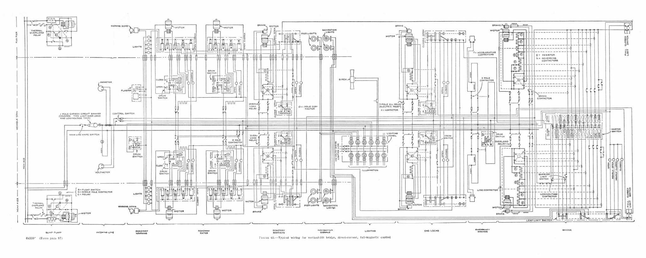
THERMAL OVERLOAD
RELAY i^i .ijf y../. ,
64559°
SUMP PUMP
(Faces page 87)
irJCOMING UNE LIGHT» NO
FiGüEE 63.—Typical wiring for vertical-lift bridge, direct-current, full-magnetic control

ELECTRICAL EQUIPMEKT 01<r MOVABLE BRIDGES 87
still further. These last two points provide for two " creeping " oi" very low speeds, and as the motor is made to slow down the moving mass quickly overhauls it, and as soon as it does, dynamic braking takes place.
The second master-switch point provides armature shunt for me- dium slow-down torque while the first master-switch point provides heavy slow-down torque. This method of deceleration (by means of armature shunt) is considered by some engineers to be a better method for dynamic deceleration than the method of dynamic brak- ing described on page 64.
Figure 63 shows the wiring diagram for the complete installation.
CONCLUSION
The wiring diagrams discussed are only a few of many possible arrangements, and the treatment given them can not, in the limited available space, include many of the points which are thoroughly covered in standard texts and descriptive technical bulletins issued by the larger electrical manufacturing companies. A careful study of these diagrams, however, should serve to give to the bridge engi- neer an understanding of fundamental principles sufficiently thor- ough to enable him to : Discuss his problems intelligently with the electrical manufacturer and contractor; formulate his requirements, in the form of a general layout plan and specifications, in a clear-cut and definite manner, and m sufficient detail to enable the electrical contractor to submit an intelligent bid ori the proposed work; check the shop drawings and wiring diagrams submitted; intelligently supervise the installation of the assembly ; and maintain the assembly in service with a minimum of repairs and service interruptions.
MAINTENANCE OF INTERLOCKING
It is important that electrical interlocking be frequently inspected and carefully maintained. The existence of electrical interlocks af- fords a sense of security that may lead to carelessness in operation. All interlocks should be carefully tested out at least once each month in the presence of the chief bridge operator and the engineer in charge of bridge maintenance.
The following blank form, prepared for reporting interlock tests on the single-leaf bascule bridge described on pages 82 to 85, illus- trates one method of tabulating and reporting these data.
Eeport blanks should be designed to fit the particular type of interlocking used, and in general, no two forms will be exactly the same unless the interlocking assemblies are duplicates. Each report should be signed by all present who witnessed the test, and should be dated. This report may prove a valuable exhibit in the event of a future accident involving an official inquiry or litigation.
In the sample interlock report given below, the data included in italics represents those items which are to be filled in during the prog- ress of the test, the balance of the subject matter being part of the printed form.

88 TECHNICAL BULLETIN 2*6 5/U. S. DEPT. OF AGRICULTURE
MONTHLY REPORT ON INTERLOCKS AND ELECTRICAL SAFETTY DEVICES FOR THE SINGLE- LEAF BASCULE SPAN OVER THE LEWIS AND CLARK RIVER, ASTORIA, OREG.
1. Roadway gate circuit: Barrier set against traffic— Barrier cleared to traffic—
North gate dead . North gate operates South gate dead South gate operates
2. Barrier circuit (gate interlock) : Both gates up (cleared to traffic), barrier dead . North gate down,
barrier dead South gate down, barrier dead^ . Both gates down, barrier operates
3. Jack circuit release: Barrier set against traffic operates Barrier cleared dead
Jack circuit drive, Leaf down operates. Leaf partly up dead..
4. Main leaf circuit: Both gates down, barrier set against traffic and rear jack driven, main
leaf dead. Both gates down, barrier set against traffic and rear jack released, main
leaf operates . Both gates down, barrier clear, rear jack released, main leaf dead Both gates down, barrier clear (but shorted) rear jack released, main
leaf operates . North gate up (by hand), barrier raised, rear jack released, main leaf
dead South gate up (by hand), barrier raised, rear jack released, main leaf
dead 5. Main leaf limit switches:
Upper operates O. K . Lower ^-operates O. K 6. Main leaf limit switch short circuits:
Upper operates 0. K Lower operates O. K 7. Start push button station : O. K. 8. Stop push button station : O. K.^ tested both gomff up and going down. 9. Indicator lamps:
For narVigation lights, O. K. For position of leaf, O. K. For barrier motor, O. K.
Above inspection made April 25, 1930. By
The following are a few simple rules with reference to the installa- tion of electrical-control apparatus, its maintenance and the renewal of parts :
All parts should be inspected at regular intervals, and should be kept free from dirt, oil, or grease.
Contact tips should be carefully inspected and replaced when worn. An ample supply of spare coils and contact tips should be kept on hand at all times.
Special attention should be paid to the maintenance of clean contacts. Oil should not be used on the main copper contacts as it tends to shorten their life. If they become pitted or rough, they should be cleaned with an emery cloth or very fine file.
All connections, binding posts, etc., should be frequently inspected for loose contacts.
Grid resistor units should be kept tightly clamped together. A complete wiring diagram of the electrical-control system should be furn-
ished the operator. (One copy of this wiring diagram should preferably be mounted under glass in the operator's house for permanent record.) This wiring diagram should be complete enough to enable the operator to trace out all connections.
Contacts with mechanical interlocks should be kept in such adjustment as to provide a very slight play. This play, however, must not be great enough to permit a circuit to be made through both contactors at the same time.
Auxiliary contactors for electrical interlocking are generally adjusted at the factory, but their adjustment should be carefully watched, In general, aux-

ELECTRICAL EQUIPMENT ON MOVABLE BBIDGES 89
iliary contacts will be made and broken simultaneously with the main contacts. For current limit protection and other uses it may be necessary to adjust these auxiliary contacts to malie circuits slightly before or slightly after the main contacts.
The line voltage should be carefully watched, and contactors should not be allowed to operate on a voltage more than 10 per cent greater than that for which they are designed, as this results in a deterioration of the insulation, increase in the pounding effect when the armature is attracted, a noisier operation, and a greater likelihood of breaking contact tips.
Where panel replacements are made, care should be exercised that the panels iire mounted in a true vertical plane so that the contactors will readily open by gravity. This also applies as a construction precaution.
The entire apparatus should be properly grounded. Grounding terminals are generally provided, except when conduit connections are used, in which case the conduits afford sufficient ground protection.
Resistors should be mounted with the grids in a vertical plane and so located as to permit of adequate ventilation. One manufacturing company recommends that 6-inch spaces be used between resistor boxes, stacked ver- tically, and that the stacks be 12 inches apart.
The heat from resistors is likely to cause damage if the grids are placed sufficiently close to any material or surface which will be damaged from heat. In this connection it may be well to point out the necessity for ample resistor capacity in the original installation, and a careful inspection of the resistors to insure that they are functioning properly.
RECENT DEVELOPMENTS IN ELECTRICAL BRIDGE CONTROL^
Among the more important modern developments of electrical apparatus for movable bridges have been the following:
(1) The adaptation and application of the variable voltage sys- tem for driving the moving span of all types of large bridges ; (2) a protective and speed-matching indicator system that makes possible the successful performance of a simplified type of vertical- lift bridge, using independent hoisting machines for each end of the span; and (3) light-sensitive relays, which have lately become a commercial product and which foreshadow greater refinement in bridge protective devices and control schemes.
VARIABLE-VOLTAGE CONTROL
Comparison of the variable-voltage system (from the standpoint of apparatus involved) with the rheostatic types described elsewhere in this bulletin, indicates all items about equal, except that the for- mer employs a direct-current generator with a driving motor or engine, where the latter uses a magnetic control board and resistor. The variable-voltage system offers the advantages of absence of com- plicated switching and control devices, an absolute guarantee against excessive torques or overload conditions which are hazardous to hoisting machinery or the electrical apparatus itself, and a system which is immune to abuse by careless operation. The motor of the motor-generator set may be arranged to operate from any com- mercial source of power, either direct current or alternating current, high or low voltage. This system is also particularly adaptable to the use of an internal combustion engine as a prime mover for the generator. Choice of variable-voltage drive for a bridge is therefore not limited by the available power service, and opportunity is of-
"^ By W. R. Wickerham, electrical engineer.
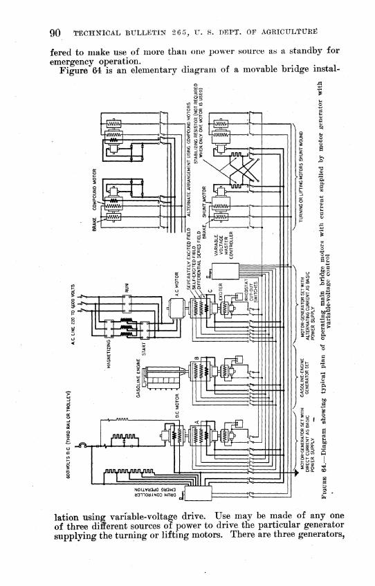
90 ÏECHÎÎICAL BULLETIN 2 6 5, V. s. DEPT. OF AGRICÜLTÜHE
fered to make use of more than one power source as a standby for emergency operation.
Figure 64 is an elementary diagram of a movable bridge instal-
lation using variable-voltage drive. Use may be made of any one of three different sources of power to drive the particular generator supplying the turning or lifting motors. There are three generators,

ELECTRICAL EQÜIPMEÍÍT OK MOVABLE BRIDGES Ôl
A, B, and C, identical in construction and in method of connection to the turning or lifting motors and each controlled by the variable- voltage master controller.
Generator A is driven by a direct-current motor. The diagram shows this motor connected to a single wire with a ground connec- tion to complete the circuit.
Generator B is driven by a gasoline engine and generator C is driven by an alternating-current motor.
If for any reason all three generators should become inoperative the turning or lifting motors may be driven with direct current (from outside source) by means of the drum controller shown on the left.
The diagram shows a pair of shunt motors connected to the gen- erators and also an alternate arrangement using compound motors.
Attention is called to the absence of any complicated switching from the main armature circuits of the machines, particularly where shunt-wound bridge motors are used. This is possible since the out- put of the generator can be made to conform to the requirements of the motor or motors for all operating conditions, both in magnitude and polarity, depending on the t3^pe used. Contactors and resistors for reversal of motor rotation and for limiting the current input are therefore unnecessary. The output of the generator is governed by an ordinary drum master controller through manipulation of the shunt fields and it is also affected by the load conditions through the medium of a differential series field. Consequently all switching for speed control of the bridge motors is limited to auxiliary cir- cuits where the current does not exceed a few amperes.
The bridge motors may be either shunt or compound wound. Shunt motors will be used where simplicity in control is of para- mount importance. Compound motors have additional complication in the form of magnetic reversing contactors, but offer a slight in- crease in efficiency as regards power consumption, when two motors are used to drive the bridge. The lower over-all efficiency of shunt motors which should be connected in parallel, is due to the use of resistors to insure an equal division of load between the motors.
Operation of the motors in parallel rather than series results in a more economical design of generator. When two motors are used to drive a bridge they are usually of such size that one may be cut out in an emergency and the bridge operated by the other motor alone. In either case, the power input to the motor or motors (for equal load) will be the same. With the parallel connection the nominal voltage of each motor is the same as that of the generator and the removal of one motor from the circuit in no way affects this voltage. The only result, so far as the motors are concerned, is that with single-motor operation all of the generator current must be absorbed by one motor instead of being divided between two. The nominal voltage of each motor when connected in series is half that of the generator, hence removal of one motor from the circuit necessitates readjustment of the generator voltage to half the normal value. The current must then be doubled in order to maintain the same power output. This is illustrated diagrammatically in Figure 65 and may be shown symbolically as follows *

92 TECHNICAL BULLETIN 26 5, XT. S. DEPT. ÔE AGBlCXTLTtTKE
Motors in parallel Motors in series Power (watts) EY.! EXI Volts per motor E E/2 Amperes per motor 7/2 / Volts per two motors E E Amperes per two motors / / Volts, generator E E Amperes, generator_..>_^ I I
Single motor of Single motor of parallel arrangement series arrangement
Power.. EXT EXi Volts per motor E E/2 Amperes per motor 2X(//2) 2X1 Volts, generator E E/2 Amperes, generator / 2X1
The generator, for motors in parallel, need be capable of delivering only E volts and / amperes, whereas the series motor connection
PARALLEL OPERATION-TWO MOTORS PARALLEL OPERATION-ONE MOTOR
SERIES OPERATION-TWO MOTORS SERIES OPERATION- ONE MOTOR
FIGURE 65.—Motor characteristics in series and parallel operation
requires that the generator be large enough to deliver E volts and 2/ amperes.
Equal division of load between the two parallel-connected motors depends upon overcoming their tendency to unload with increase in load. Three factors determine the flow of current through the arma- ture of any motor, namely, the line voltage, the resistance in the armature circuit, and the counter electromotive force.
/= ^line-CEMF
B or.
£'une = /^ + CEMF
(1)
(2)
The latter equation states tliat the line voltage is equal to the resistance drop and counter electromotive force of the armature. If

ELECTRICAL EQUIPMENT ON MOVABLE BRIDGES 93
an increase in current is accompanied by an appreciable increase in either of the latter factors there will be a reaction against this increase in current and hence the desired unloading tendency. Both motors (designated as A and B) operate from the same impressed, voltage ; therefore the following equation is true :
I^R^ + CEMF^^E=IBRB + CEMFB (3)
Equation (3) shows that for balanced conditions of load the total counter voltages in each motor circuit are equal.
For constant load, any increase in current through one motor must be accompanied by a like decrease in current through the other motor and therefore
{IA + ÍA) RA + CEMFA = (/s - ÍB) BE + CEMFB (4)
This equation may be considered to apply to two shunt motors. The total counter voltages are unbalanced by an amount equal to the difference in resistance drop, and are higher in the circuit carrying the larger current. The unbalance, however, is very slight on ac- count of the small numerical value of Ä, and can not be relied upon as a means for balancing the current in the two motors. The addition of a slight amount of resistance in series with each motor, brings the total resistance drop to a value that will produce the necessary result. The equation then becomes
(IA + íA) (RA + r^) + CEMF^ = {IB- ÍB) (RB + r^) -hCEMFa (5)
where r= external résistance. This external resistance will cause a decrease in overall efficiency not exceeding 4 per cent.
When the motors have compound windings, the quantity CEMF, in the above equations is affected by change in current. Counter electromotive force is proportional to the motor speed and field flux, and the latter is roughly proportional to the ampere-turns producing the flux. This may be expressed
CEMF=KNIS,
where K=the numerical multiplier iV=turns in series field winding /=motor amperes /S'=motor speed
Since N and S are the same for both motors, the above may be written
CFMF=KJ
where K-^'^KNS. Equations (3) and (4) when applied to com- pound motors may be written
IARA-^-KJA^IBRB-^KJB (6) (/^ + i^) Rj, + {IB + i A) K, = {IB - íB) RB + (IB - ÍB)K, (7)

94 TECHNICAL BULLETIN 2 6 5^ U. S. DEPT. OF AGRICULTURE
The unbalance in the counter voltage due to the unbalance current, ¿, is sufficient to guarantee against a large value of this current. This unbalance is caused principally by the factor {lXi)K^^ in other words, by a change in the generator CEMF.
Conclusions in regard to the use of motors with variable voltage control may be briefly stated as follows : Shunt-wound or compound- wound motors may be used. Both types provide approximately equal performance as regards speed and torque. Shunt motors offer sim- plicity and economy in wiring and apparatus, but operate at slightly reduced efficiency when two motors are used. Compound motors offer maximum efficiency, but involve increased complication in wiring and apparatus.
The generators used with this system are arranged to operate at constant speed, and have a special design of field windings. Three separate field windings are used, two of which are of the shunt type, and the third, a series type. One of these shunt wind- ings, called the separately excited field, is energized from a source of constant potential, usually supplied by an exciter directly coupled to the generator. The other shunt winding, called the self- excited field, obtains its energy from the terminals of the generator itself. The series winding is connected directly in the mam circuit of the generator, and its polarity is such that it opposes the magneto- motive force of the two shunt windings. The reactions of these three field windings are such that the terminal voltage of the gen- erator drops slightly as the load increases from zero to normal, but with further increase in load drops off very rapidly permitting the motors to stall at a current which is not more than two or three times the normal load current for bridge movement. This voltage characteristic is illustrated by curve E5—I3 in Figure 66.
The speed-torque characteristics are approximately the same as the voltage-load characteristics, since the motor speed varies directly as the generator voltage and the motor torque substantially as the generator current. It is obvious from this that the system in- herently provides a definite maximum torque which it is impossible to exceed. It is therefore impossible to subject the machinery to strains or overloads by careless operation, and since there are no protective relays there can be no damage due to their failure to function. This safety in operation may result in the reduction of safety factors in the strength of the hoisting machinery, since such machinery is ordinarily designed to withstand excessive torques and shock, such as might be delivered by other types of drive under abnormal conditions.
The magnitude of the generator voltage, and hence the speed of the motors, is regulated by a master controller of the usual type, operating principally in the separately excited field circuit. Figure 66 shows three curves labeled ^1-/1, ^2-/25 and E^-I^. These are produced, respectively, by the first three power points on the master controller, and are the net result of the reactions of the separately excited field and the differential series field. When the master controller is moved to the first power point, the generator voltage tends to rise to E^. Current immediately flows in the main circuit and, due to the differ- ential action of the series field, the ampere turns of the separately excited field are nullified to a certain extent so that a voltage only equal to RI^ (resistance drop of the circuit) appears. This circu-

ELECTRICAL EQUIPMENT ON MOVABLE BEIDGES 95
lates a current of /i amperes. The current A may be in excess of normal, and if so, the motors will accelerate and, due to the accom- panying rise in CEMF, the armature current will decrease with rise in speed. Decrease in armature current results in decreased differ- ential field action, with the result that the generator voltage now rises in proportion to increase in motor speed to a limiting value of Ex for no load. The reaction for the second and third power points are identical.
It will be noted that the maximum current /g, which flows in the armature circuits, is not affected by the last two power points of the controller which add the self-excited shunt field. At the point of maximum current the ampere turns of the separately excited field are neutralized by the ampere turns of the differential field. Curves JF4-/3 and £"5-/3 are produced by the self-excited field, governed by the last two power points on the controller, and it will be noted that these result in increase in genera- tor voltage (also motor speed) but not in current. The maximum am- pere turns of the self-excited field do not have sufficient magnitude to build up or maintain the gen- erator voltage from its action alone. Initial voltage must be es- tablished by the separately excited field before the self-excited field can become effective. Thus when the separately excited field is neu- tralized by the differential wind-
riORMALTORQ.Ut
MAXIMUM TORQyt^^
I GENERATOR AMPERES- |¿ ^VOLTAGE CURVES '."^
MOTOR SPEED- TORQUE CURVES
HORSE POWER IS
mg, GENERATOR AMPERES-MOTOR TORÛUE
FIGURE 66.—Characteristic curves for variable-voltage operation
the self-excited field also collapses. The curved shape of the curves E^r-Iz and E^-I^ is due to the effects of a saturation of the generator field poles. There is an excess of total field ampere turns when operating on curve E^ in the region of full load. With medium increase in load the loss of net ampere turns in the field windings does not appreciably effect the field flux on account of pole satura- tion. When the field flux reaches the point where saturation no longer exists, there is a rapid collapse as illustrated by the sharp drop in curve E^-Iz for high current value.
The adjustment of voltage and current as the master controller is moved from point to point never occurs abruptly, due to an inherent time lag in the flux change in the generator fields, and also because the differential field always tends to oppose any change in the exist- ing load current. The result is a cushioning effect on the motor torque. The master controller may be jerked from the off position to the full on position without shock to the machinery. The load current in this case rises to maximum at a smooth rate in approx- imately one to two seconds. The gradual rise in current permits slack to be taken up in gears before heavy torque appears.
Decrease in generator voltage on returning the master controller toward the off position results in its becoming less than the motor CEMF, which is always proportional to the bridge speed. The motors, therefore, act as generators, reversing the flow of main cur- rent and supplying negative or décelerating-torque provided the load

96 TECHNICAL BULLETIN 2 6 5, U. S. DEPT. OF AGRICULTUKE
is overhauling. In effect, this means that for each point of the master controller there is a fairly definite motor speed, regardless of whether the load torque is positive or negative. This feature is of some importance on bridges which are not exactly counterbalanced throughout full travel, since there is no tendency to " run away " such as would be the case with certain types of rheostatic controllers when the load is overhauling. This feature is important on any bridge for purposes of " slow down," resulting in greatly reduced duty on friction-type brakes.
A study of Figure 66 indicates that the power input into this sys- tem varies from theoretical zero with the motors operating at max- imum speed and no load, to a maximum at some intermediate value of speed and load, and back to zero with the motors stalled at maxi- mum torque. Horsepower is the product of voltage, current, and a constant. Zero horsepower at full speed and no load is due to the absence of the current factor, and at " stall " it is due to the absence of the voltage factor. This is a most important feature where the generator is driven by an internal-combustion engine. With an ordi- nary type of generator and rheostatic control, the power input would increase directly as the generator current output. The power of the engine for such a system would need to be based upon the maximum emergency currents required for operation under unusual ice or wind loads and the engine would therefore be considerably larger than required for normal operation. The maximum power input for the variable-voltage system on the other hand, occurs in the region of normal load current, and, therefore, the engine need be only large enough to supply this power. The engine will never be required to deliver power in excess of this, since the heavy emer- gency torques are handled at reduced power. The ratings of inter- nal-combustion engines are generally such that they have little reserve power, but since the variable-volt age system eliminates the necessity for reserve power a closely rated engine may be safely used.
General conclusions on the performance of the variable voltage system as a whole may be summed up as follows :
The machines themselves are practically immune to damage from overload due to careless operation.
The maximum torque is definiteljr limited, eliminating the possi- bility of damaging mechanical strains in machinery.
Protection is afforded against shock or jar due to careless opera- tion and the system is almost ideal in giving smooth acceleration.
Slow down (or retarding torque) can be obtained with an over- hauling load.
Certain advantages may be realized in the applicatioin of engine prime movers.
Full automatic starters, controlled remotely by start and stop push buttons on the operator's board can be used for motor gener- ator sets. Where the motor uses alternating current the starter may be either of the line or reduced-voltage type. The line-type starter employs a single contactor, or oil circuit breaker where the voltage is above 600, and full-line voltage is applied directly to the motor terminals in starting. The reduced-voltage type makes use of two or three switching devices together with an autotrans- former or reactor for the purpose of applying from 50 to 80 per cent normal voltage to the motor at starting. The current drawn

ELECTRICAL EQUIPMENT OK MOVABLE BRIDGES 97
from the line at the instant a line starter is closed may reach a value approximately 600 per cent of normal, but for the reduced- voltage starter the current may be limited to only 200 or 300 per cent of normal. The driving motor for the motor-generator set for a large bridge may be rated as high as 500 horsepower in some cases, and a current inrush approximating six times normal current would cause objectionable surges and voltage fluctuations on a pub- lic-service line where lighting circuits are part of the connected load. The bridge engineer will probably be compelled to use the reduced-voltage type starter in most cases, due to power-company regulations which prohibit excessive and abrupt demands on their lines.
Auxiliary and control circuits handling magnetic brakes, motor field, generator fields, magnetic contactors and relays, electrically operated circuit breakers, etc., can be supplied with power at 115, 230, or 550 volts direct current by an exciter on the main generator shaft. Another arrangement makes use of a 125-volt storage battery for control circuits, which may also be used for emergency lighting service, in the event of a failure of alternating-current power. This latter arrangement, of course, necessitates the use of a small auxiliary motor-generator set for charging the battery.
PROTECTIVE AND SPEED-MATCHING INDICATORS FOR VERTICAL- LIFT BRIDGES
The common type of vertical-lift bridge has the lifting machinery mounted on the moving span. This has been necessary, perhaps, since the same drum can be arranged to lift both ends of the bridge, thus insuring that the span remains level throughout the lift.
A few bridges have been recently constructed, in which there is no machinery on the moving span and which use separate hoisting machines and motors for each end of the span, these being located in the tops of the stationary towers. There appears to be consider- able mechanical economy in this design, particularly in lifting cables and accessories, but it is essential that the two hoisting machines operate in synchronism in order that the 'bridge be maintained level during the lifting operation. The maximum amount of permissible skew on any of the completed installations has not exceeded approxi- mately 12 inches in 150 feet. The electrical problem consists, of course, in maintaining the average speed of the motors equal and in permitting no transient variation in speed that will cause a skew greater than the allowable limit.
The control system used so far has made use of a system of skew indication conveniently arranged with a leveling master controller. In addition to this an ultimate skew limit switch has been provided, and arranged to bring the bridge to a stop by cutting off power and setting brakes whenever the skew approaches the allowable limit. The latter device is in the nature of a positive safety factor, and does not depend upon the operator, aS in the case oi the leveling scheme.
The motors in the towers are all controlled from a common master controller located in the operator's house. The arrangement pro- vides that all control functions such as applying power, closing ac- celerating contactors, etc., occur simultaneously for each drive. This
64559°—31 7
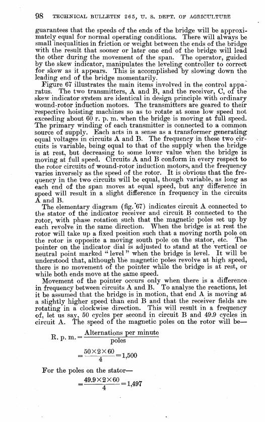
98 TECHNICAL BULLETIN 2 6 5^ TJ. S. DEPT. OF AGRICULTURE
guarantees that the speeds of the ends of the bridge will be approxi- mately equal for normal operating conditions. There will always be small inequalities in friction or weight between the ends of the bridge with the result that sooner or later one end of the bridge will lead the other during the movement of the span. The operator, guided by the skew indicator, manipulates the leveling controller to correct for skew as it appears. This is accomplished by slowing down the leading end of the bridge momentarily.
Figure 67 illustrates the main items involved in the control appa- ratus. The two transmitters, A and B, and the receiver, C, of the skew indicator system are identical in design principle with ordinary wound-rotor induction motors. The transmitters are geared to their respective hoisting machines so as to rotate at some low speed not exceeding about 60 r. p. m. when the bridge is moving at full speed. The primary winding of each transmitter is connected to a common source of supply. Each acts in a sense as a transformer generating- equal voltages in circuits A and B. The frequency in these two cir- cuits is variable, being equal to that of the supply when the bridge is at rest, but decreasing to some lower value when the bridge is moving at full speed. Circuits A and B conform in every respect to the rotor circuits of wound-rotor induction motors, and the frequency varies inversely as the speed of the rotor. It is obvious that the fre- quency in thé two circuits will be equal, though variable, as long as each end of the span moves at equal speed, but any difference in speed will result in a slight difference in frequency in the circuits A and B. ^
The elementary diagram (fig.'67) indicates circuit A connected to the stator of the indicator receiver and circuit B connected to the rotor, with phase rotation such that the magnetic poles set up by each revolve in the same direction. When the bridge is at rest the rotor will take up a fixed position such that a moving north pole on the rotor is opposite a moving south pole on the stator, etc. The pointer on the indicator dial is adjusted to stand at the vertical or neutral point marked " level " when the bridge is level. It will be understood that, although Ihe magnetic poles revolve at high speed, there is no movement of the pointer while the bridge is at rest, or while both ends move at the same speed.
Movement of the pointer occurs only when there is a difference in frequency between circuits A and B. To analyse the reactions, let it be assumed that the bridge is in motion, that end A is moving at a slightly higher speed than end B and that the receiver fields are rotating in a clockwise direction. This will result in a frequency of, let us say, 50 cycles per second in circuit B and 49.9 cycles in circuit A. The speed of the magnetic poles on the rotor will be—
^ Alternations per minute R.p.m. = - ^^^
50X2X60 , ^^^ = ^ = 1,500
For the poles on the stator—
49.9X2X60 , ,^^ = 1 = 1,497
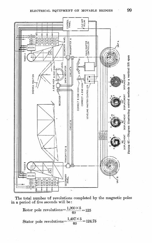
ELECTRICAL. EQUIPMENT OIT MOVABLE BRIDGES 99
The total number 'of revolutions completed by the magnetic poles in a period of five seconds will be :
Eotor pole revolutions = h^^>^^ = ^25 60
1497 X 5 Stator pole revolutions = ' ^^ =124.75

100 TECHITICAL BULLETIN 2 6 5^ U. S. DEPT. OF AGRICULTURE
This indicates that the magnetic poles on the rotor will lead the poles on the stator by one quarter revolution (90°) at the end of a 5-second period assuming that they were in synchronism at the start. Actually, however, this does not occur. The magnetic reaction be- tween the poles on the stator and rotor are such that a north pole on the rotor must always remain exactly opposite a south pole on the stator, therefore the rotor must rotate mechanically one quarter revolution in the opposite direction to compensate for the loss in the speed of its field. The movement takes place at a uniform rate, and at the end of five seconds the indicator dial hand will have rotated 90° in a counterclockwise direction and will indicate A end high.
If it had been assumed that end B traveled at the higher speed, the magnetic poles of the rotor would have made 124.75 revolutions while the stator poles revolved 125 turns. In this case the rotor must rotate mechanically one quarter revolution in a clockwise direc- tion to compensate for the higher speed of the magnetic field. At the end af the 5-second period the dial hand will have rotated 90° in a clockwise direction, indicating B end high. ~ The deflection of the dial hand is of course proportional to the skew of the bridge. The dial may therefore be calibrated in inches of skew.
Any tendency of the bridge to become skewed while in motion is at once brought to the operator's attention by a movement of the indicator hand, one way or the other. An arrangement has been worked out that eliminates any necessity for the operator to interpret the movements of the indicator. This has been accomplished by mounting the leveling controller immediafely beneath the indicator, so that the movement of the vertical handle is similar to the swing of the indicator hand. The operator corrects for skew by moving the controller handle in the opposite direction to the swing of the indica- tor hand.
Existing installations use the leveling scheme described above, with the actual leveling depending upon a manipulation of a device by the operator. With transmitters and receiver of increased size, there is ixo reason why the indicator could not be replaced by a contact- making device arranged to perform the same function as the leveling controller. An arrangement of this kind would automatically tend to maintain the bridge level without attention by the operator.
The ultimate-skew switch shown in the diagram, is a positive- circuit interrupter, arranged to stop all motors and set all brakes in case the bridge skew approaches the maximum allowable limit.
The circuit interrupter includes two units, one of which is geared to the hoisting machinery at each end of the bridge. Each unit con- sists of a rotating drum, or face plate, carrying six contact segments. One of the segments on each drum makes contact throughout 360° of rotation and serves as a common feed for the drum. Each of the other five segments are in contact somewhat less than 180°, and are spaced at equal distances around the face plate. The five fingers of unit A in contact with these latter segments are connected to the corresponding fingers on unit B.
The action* of the two units is such that they are connected to- gether electrically, through one, two, or three of the five conductors as long as they are not more than approximately 120° out of phase ;

ELECTRICAL EQUIPMENT ON MOVABLE BRIDGES 101
that is, as long as a point on one face plate does not lag or lead a corresponding point on the other by more than 120°, as both rotate, the circuit between the two is not broken. When the lag or lead exceeds this angle, the circuit will be broken momentarily five times for each 360° of revolution. The first momentary interruption of the circuit trips a cut-off relay, which can not be permanently reset until the bridge skew has been corrected and all master controllers brought to the off position.
Figure 67 shows a series of four sketches with the two face plates superimposed upon each other with varying degrees of displacement. The fingers of both units will fall along the same position line in all cases. Unit A carries left-hand spiral shading and unit B carries right-hand shading. Overlapping parts of the segments are shown in black, while parts of the segments not overlapping carry line shading. A circuit from one unit to the other can only be completed where the segments overlap, therefore the fingers that fall in the black areas will complete a circuit between the two units via their respective circuits.
Sketch No. 1 shows the units exactly in phase with the bridge level. It will be noted that two or three circuits are always com- pleted between the units. At position a circuits 1, 4, and 5 are com- pleted, at & circuits 1 and 5, at c circuits 1, 2, and 5, at ¿ circuits 1 and 2, at e circuits 1, 2, and 3, etc. Sketch No. 2 shows unit B lagging by 90°, caused by the bridge being skewed with A end high. This sketch shows that at least one circuit is always completed between the two units, and part of the time two circuits are completed. At posi- tion a circuit 4 is complete, at ah circuits 4 and 5, at & circuit 4, at d circuit 1, etc. Sketch No. 3 shows a displacement of 120°. A circuit between the two units is not always complete for this displacement. At position Œ circuit 4 is complete, at ab all circuits are incomplete. Circuit 5 is established for positions h and c. For this displacement there will be five momentary interruptions for every complete revo- lution of the switches. The skew corresponding to 120° displacement of tlie limit switches therefore represents the maximum amount of skew attainable, provided both ends of the bridge are in motion.
Sketch No. 4 shows the result of 180° displacement, with all cir- cuits incomplete at all times during rotation of the switches. This amount of displacement can only be approximated by moving one end of the bridge alone. It is apparent that all the cross-hatched area shown in sketch No. 3 will not disappear until the displacement approaches 180°. It is only possible to attain this degree of dis- placement by moving one end of the bridge with the other at a stand- still. This will be apparent if it is assumed the fingers on position h in sketch No. 3, and then consider that unit B be rotated in a counter- clockwise direction. The overlapping full black area at position h will not disappear until unit B has rotated nearly 180°, and circuit 3 will be maintained until this occurs.
The interrupter therefore does not break the circuit at a fixed point of skew, but may cut out anywhere within fixed limits. These limits occur between 120° and 180° of displacement for the units, and this may be translated into any desired amount of bridge skew by a choice of suitable gearing. Assuming a maximum permissible skew of 12 inches, the gearing should preferably be such that the maximum cut-

102 TECHNICAL BULLETIlSr 2 6 5^ U. S. DEPT. OF AGKICULTUEE
out occurs with a skew of about 9 inches. The minimum cut-out would then occur at 6 inches skew (both ends in motion).
LIGHT-SENSITIVE RELAYS
One of the most important problems in connection with movable bridges has to do with the design of a reliable protective system. The bridge and operating machinery must be protected against damage due to overtravel, or incorrect operating sequence, and provision must be made for the protection of bridge traffic. This has been accomplished in the past by the use of mechanically op- erated limit switches of various types, which are fully described elsewhere in this bulletin.
The new light-sensitive relays which have recently appeared on the market possess characteristics which may permit an improve- ment in the design of these protective devices in three respects, namely:
(1) Elimination of complicated mechanical operating devices for limit switches.
(2) Greater refinement in precision-type limit-switch applications. (3) Elimination of submarine or flexible aerial cables between
moving and stationary parts of bridges. Light-sensitive relays may be arranged either to make or break
a contact, and both of these performances may be brought about by either cutting off a beam of light or establishing the beam. This can be accomplished either by moving the source of the light with respect to the light receiver or by interposing a shutter between a fixed light source and the receiver. In general, where the relay is applied for the purpose of limiting travel, a scheme which de- pends upon an interruption of the light beam should be used so that a failure of the light source will stop the machinery and prevent damage. Those arrangements where the relay depends upon estab- lishing the light beam between the source and the light-sensitive element should be restricted to the sequence interlocking system, where a failure can be taken care of by the ordinary interlocking by-pass or short-circuiting switches.
The only operating device required for use with light relays will consist of a member or shutter for the purpose of interrupting the light beam. This will not always be required, since the same purpose can be accomplished by moving the source of light with respect to the relay. This sort of operating device can not be thrown out of adjustment by dimensional changes in the bridge due to varying temperature, such as may occur with certain mechanical arrange- ments and does not suffer from impact when engaged by high-speed moving parts.
There are a few limit-switch applications on bridges, where it is perhaps impossible to design a mechanically operated switch that will function with the desired precision. ï'hese generally may be classified as switches operated directly by a moving member and which must go through a complete cycle of opening and closing with continuous movement of the actuating member. An example of this is a switch designed to close a contact when a double-action swing bridge is in a fully closed (neutral) position. Any ordinary

ELECTRICAL EQUIPMENT ON MOVABLE BRIDGES 103
mechanically operated switch that might be applied for this purpose will maintain its contacts closed for a distance of from 1 to 3 inches of travel on either side of the neutral for the end of the bridge. This is not a very high degree of accuracy, and, moreover, such accuracy may be impaired by temperature dimensional variations in the moving span. A light-relay system arranged with the light source on the rest pier and the relay on the moving span, and em- ploying an aperture for the light beam in the form of a vertical slit, could be arranged to confine the operating range to within at least one-fourth inch of the exact fully closed position.
For bridges of the swing and vertical-lift types the operator's house is generally located on the moving span. Roadway gates, warning lights and signals, traffic barriers, etc., are located on the bridge approaches. Power for operating and controlling these de- vices is brought from the operator's house on the moving span by multiconductor submarine or aerial cables. These cables may be (for the greater part at least) eliminated and the traffic gates, lights, and signals controlled by light relays located on the approaches and actuated by light projectors mounted on the moving span. It will be noted that this scheme, besides controlling the roadway devices, also automatically provides the necessary interlocking, inasmuch as it will be impossible to inadvertently operate any of the roadway de- vices with the span open, since the light beam from the projectors can not engage the relays in any other than the full-closed position.
APPENDIX
In much of the discussion and many of the figures contained in this bulletin no attempt has been made to follow the exact standards of terminology adopted by the electrical manufacturing trade, nor to strictly adhere to established conventional symbols. This deviation from standard convention was adopted in the interest of clarity of expression, and because the strict convention meth- ods of representation appear, in certain instances rather too schematic to clearly illustrate the text.
It therefore appears advisable to include, at this point, certain extracts from the N. E. M. A. (National Electrical Manufacturers' Association) Indus- trial Control Standards, as in effect on January 1. 1931.
DEFINITIONS
Electric controller.—^An electric controller is a device, or group of devices, which serves to govern, in some predetermined manner, the electric power delivered to the apparatus to which it is connected.
Full magnetic controller.—^A full magnetic controller is a controller hav- ing all of its basic functions* performed by electromagnets.
Semimagnetic controller.—^A semimagnetic controller is a controller having part of its basic functions performed by electromagnets and part by other means.
Manual controller.—A manual controller is a controller having all of its basic functions performed by hand.
Drum controller.—^A drum controller® is a controller which utilizes a drum switch as the main switching element.
Starter.—A starter is a controller ^^ designed for accelerating a motor to normal speed in one direction of rotation.
Automatic starter.—An automatic starter is a starter designed to .automati- cally control the acceleration of a motor.
8 By basic functions is usually meant acceleration, retardation, line closing, revers- ing etc.
»A drum controller usually consists of a drum switch and a resistor. i«A device designed for starting a motor in either direction of rotation includes the
additional function of reversing and should be designated a controller.

104 TECHNICAL BULLETIN 2 6 5^ U. S. DEPT. OF AGRICULTURE
Autotransformer starter.—^An auto transformer starter is a starter having an autotransformer to furnish a reduced voltage for starting. The device includes the necessary switching mechanism and is frequently called a com- pensator or autostarter.
Contact,—^A contact is a conducting part designed to be united by pressure to another conducting part for the purpose of carrying current.
Switch.—^A switch is a device for making, breaking, or changing the con- nections in an electric circuit.
Discormecting switch.—^A disconnecting switch is a switch which is intended to open a circuit only after the load has been thrown off by some other means.
Motor circuit switch.—^A motor circuit switch is a switch intended to open under load and will break 150 per cent of its rated load. Such a switch may be used to stop the motor under normal running conditions and also provide means for disconnecting the controller and motor from the line when it is necessary to make repairs.
Drum switch.—A drum switch is a switch having electrical connecting parts in the form of fingers held by spring pressure against contact segments or sur- faced on the periphery of a rotating cylinder or sector.
Master switch.—^A master switch^ is a switch which serves to govern the operation of contactors and auxiliary devices of an electric controller.
Contactor.—^A contactor is a device for repeatedly establishing and inter- rupting an electric power circuit.
Magnetic contactor.—^A magnetic contactor is a contactor actuated by electro- magnetic means.
Resistance.—Resistance is the opposition offered by a substance or body to the passage through it of an electric current and converts electric energy into heat. Resistance is the reciprocal of conductance.
Resistor.—^A resistor is a device used primarily because it possesses the property of electrical resistance. A resistor as used in electric circuit for purposes of operation, protection, or control, commonly consists of an aggre- gation of units.
Rheostat.—A rheostat is a resistor which is provided with means for readily varying its resistance.
Resistive conductor.—A resistive conductor is a conductor used primarily because it possesses the property of electrical resistance,
KINDS OF PROTECTION
Low (or under) voltage protection.—^Low (or under) voltage protection is the effect of a device operative on the reduction or failure of voltage to cause and maintain the interruption of power to the main circuit.
Low (or under) voltage release.—Low (or under) voltage release is the effect of a device, operative on the reduction or failure ' of voltage, to cause the interruption of power to the main circuit but not to prevent the reestab- lishment of the main circuit on return of voltage.
Phase-failure protection.—Phase-failure protection is the effect of a device operative upon the failure of power in one wire of a polyphase circuit, to cause and maintain the interruption of power in all of the circuit.
Phase-reversal protection.—Phase-reversal protection is the effect of a device operative on the reversal of the phase rotation in a polyphase circuit, to cause and maintain the interruption of power in all of the circuit.
Overload protection.—Overlosia protection is the effect of a device operative on excessive current to cause and maintain the interruption of current now to the device governed. When it is a function of a controller for a motor, the device employed shall provide for interrupting any operative overloads,^ but shall not be required to interrupt short circuits.
RELAYS
Relay.—^A relay is a device that is operative by a variation in the conditions of one electric circuit to effect the operation of other devices in the same or another electric circuit.
^ A master switch may be automatic, as a float switch or pressure regulator. It may be manually operated, as a drum, push button, or, knife switch.
^ By operating overload is meant a current not in excess of six times the rated current for alternating-current motors, nor in excess of four times the rated current for direct- current motors.

ELECTRICAL EQUIPMEKT ON" MOVABLE BRIDGES 105
Phase-rotation relay.—A phase-rotation relay is a relay which functions in accordance with the direction of phase rotation.
Current relay.—^A current relay is a relay which functions at a predetermined value of current. A current relay may be either an oyercurrent relay or an undercurrent relay.
Overload relay.—An overload relay is an overcurrent relay in the circuit of a motor which functions at a predetermined value of the current to cause the disconnection of the motor from the line.
Voltage rela/y—^A voltage relay is a relay which functions at a predetermined value of voltage. A voltage relay may be either an overvoltage relay or an undervoltage relay.
Differential relay. "—^A differential relay is a relay which functions by reason of the difference between two quantities such as current or voltage, etc.
Frequency rela/y.—^A frequency relay is a relay which functions at a prede- termined value of frequency. A frequency relay may be either an overfre- quency relay or an underfrequency relay.
Temperature relay.—K temperature relay is a relay which functions at a pre- determined temperature in the apparatus protected.
Open-phase relay.—^An open-phase relay is a relay which functions by reason of the opening of one phase of a polyphase circuit.
Step-hack reloAf^^—K step-back relay is a relay which operates to limit the current peaks of a motor when the armature or line current increases. A step- back relay may, in addition, operate to remove the cause of the limitation to the current peaks of a motor when the armature or line current decreases.
QUALIFYING TERMS OF RELAYS
Notching.—^A qualifying term applied to any relay indicating that a pre- determined number of separate impulses are required to complete operation.
Inmerse time.—Inverse time is a qualifying term indicating that there is purposely introduced a delayed action, which delay decreases as the operating force increases.
Definite time.—A- qualifying term applied to any relay indicating that there is purposely introduced a delay in action, which delay remains substantially constant regardless of the magnitude of the quantity that causes the relay to function. (For quantities slightly above the minimum operating value, the delay may be inverse.)
Instantaneous.—^A qualifying term applied to any relay indicating that no delay is puriwsely introduced in its action.
PROPERTIES AND CHARACTERISTICS OF APPARATUS
Pi€k-up voltage {or current).—The pick-up voltage (or current) is the volt- age (or current) at which a magnetic contactor starts to close under condi- tions of normal operating temperature.
Seating voltage {or current).—The seating voltage (or current) is the volt- age (or current) necessary to seat the armature of a magnetic contactor from the position at which the contacts first touch each other, under conditions of normal operating temperature.
Beating gap.—The seating gap is the distance between the armature and the i'enter of the core of a magnetic contactor when the contacts first touch each other.
Drop-out voltage {or current).—^The drop-out voltage (or current) is the voltage (or current) at which the contacts of a magnetic contactor open under <îonditions of normal operating temperature.
MISCELLANEOUS
Conducting parts.—Conducting parts of control apparatus are those designed to carry current or which are conductively connected therewith.
Grounded parts.—Grounded parts are those parts which are so coïmected that, when the installation is complete, they are in electrical connection with the earth.
w This term includes relays heretofore known as " ratio balance relays," " biased relays," and ** percentage differential relays."
1* When used with a motor having a. flywheel, the relay causes the momentary transfer of stored energy from the flywheel to the load, but does not limit the current peaks if the load is sustained for a considerable interval after the relay operates.

106 TECHNICAL BULLETIN 2 6 5;, U. S. DEPT. OF AGRICULTURE
Magnet brake.—A magnet brake is a friction brake controlled by electro- magnetic means.
Jogging service.—Jogging or inching is the quickly repeated closure of the circuit to start a motor from rest for the purx)ose of accomplishing small move- ments of the driven mächine.
Control cirouit transformer.—^A control circuit transformer is a voltage transformer utilized to supply a voltage suitable for the operation of shunt-coil magnetic devices.
ControUer-wi/ring diagram.—^A controller-wiring diagram is a diagram show- ing the electrical connections between the parts comprising the controller, and indicating the external connections.
EiTtemal controller wiring diagra/m.—^An external controller wiring diagram is a diagram showing the electrical connections between the controller terminals and outside points, such as connections from the line to the motor and to auxiliary devices.
Controller-oonsiruction diagram.—K ^ontroUerrconstruction diagram is a diagram indicating the physical arrangement of parts such as wiring, buses,, resistor units, etc. Example : A diagram showing the arrangement of grids and terminals in a grid-type resistor.
Elementary-controller diagram.—^An elementary-controller diagram is a dia- gram using symbols and an elementary plan of connections to illustrate, in simple form, the motor circuits and the scheme of control.
Control seqiience tahle.—^A control sequence table is a table, indicating the connecting devices which are closed for each successive position of the controller.
Fuses.—^A fuse is an overcurrent protective device with a circuit opening fusible member directly heated and destroyed by the current passing through it.
Thermal cut-out.—A thermal cut-out is an overcurrent protective device that contains a heater element " in addition to and affecting a fusible member which opens the circuit.
Barrier.—^A barrier is a partition for the insulation or isolation of electric circuits or electric arcs.
RATING, PERFORMANCE, AND TEST
Amhient temperature.^^—^Ambient temperature is the temperature of the air or water which, coming into contact with the heated parts of a machine, carries off their heat. (See A. I. E. E. Rule 3,000.")
Rating.^^—^A rating of a machine, apparatus, or device is an arbitrary designation of an operating limit.
For the purpose of this section the rating of a controller is based upon the power governed, the duty, and the service required. Standard ratings do not provide for overload capacity.
The rating^ of control apparatus in general shall be expressed in volts, amperes, horsepower, or kilowatts, as may be appropriate.
Resistors shall be rated in ohms and amperes and class of service. The various kinds of rating recognized are :
Continuous rating.—The continuous rating defines the load which can be carried for an unlimited period, without causing any of the limitations estab- lished herein to be exceeded.
Eight-hour rating.—The 8-hour rating of a magnetic contactor is its ampere- carrying capacity for eight hours under conditions of free ventilation starting with new, clean contact surfaces and not exceeding N. E. M. A. temperature limitations and with the operating coil circuit excited at full-rated voltage.
^ The heater element may be a coil, a resistive conductor, or any heat-producing means responding to the current.
18 Ambient temperature is commonly known as " room temperature " in connection with air-cooled apparatus not provided with artificial ventilation.
1'^ National Electrical Manufacturers' Association rules specify that the standard ambient temperature of reference, when the cooling medium is air, shall be 40" C.
" A rating is arbitrary in the sense that it must necessarily be established by definite fixed standards, and can not, therefore, indicate the safe operating limit under all condi- tions that may occur in service.
^ For convenience in application starters are frequently rated in horsepower. In such cases the starter rating is the horsepower rating of the largest motor for which the starter Is designed to be used.

ELECTRICAL EQUIPMENT ON MOVABLE BRIDGES 107
The 8-hour rating is the recognized standard rating. Any other time capacity- required should be specified in definite terms.
NOTE.—" Continuous rating " with respect to contactors is considered as an indefinite term.
The service characteristics of contractors are recognized as determining their applicability to various duty cycles such as—
Maximum circuit closing capacity. Maximum interrupting capacity. Wearing qualities under given frequency of operation. Periodic rating.—The periodic rating defines the load which can be carried
for the alternate i)eriods of load and rest specified in the rating, the apparatus starting cold, and for the total time specified in the rating without causing any of the limitations established herein to be exceeded.
Standard periodic ratings,—Standard periodic ratings are as follows : 15 seconds load every four minutes, or one-sixteenth time rating. 30 seconds load every four minutes, or one-eighth time rating. 45 seconds load every four minutes, or three-sixteenths time rating. 1 minute load every four minutes, or one-fourth time rating. iy2 minutes load every four minutes, or three-eighths time rating. 2 minutes load every four minutes, or one-half time rating.
In each case the alternate periods of load and rest shall be continued for one hour.
Service classifications of motor-control resistors.—(1) Numbers used to desig- nate the resistors required for different classes of control service are given in Table 4.
(2) The test on starting and intermittent-duty resistors to meet the above classification shall be continued for one hour. They are primarily designed for use with motors requiring an initial torque corresponding to the current value for the class of resistors specified and requiring an average (root-mean- square) accelerating current in any case of 125 per cent of full-load value.
(3) The test on continuous-duty resistors shall be continued until maximum temperature is reached. They shall be capable of carrying full-load current on any point where the resistance will permit that amount of current to pass.
TABLE 4.—Classification of resistors for periodic rating '
Approximate percentage of full- load current on the first point
15 sec- onds out
of 4 minutes
30 sec- onds out
of 4 minutes
45 sec- onds out
of4 minutes
1 minute out of 4 minutes
11^ min- utes out
of 4 minutes
2 minutes out of 4 minutes
Contin- uous duty
25 ..... Number
11 12 13 14 15 16
Number 31 32 33 34 35 36
Number 41 42 43 44 45 46
Number 51 52 53 64 55 56
Number 61 62 63 64 65 66
Number 71 72 73 74 75 76
Number 91
60.. 92 70 93 100 : - 94 150- _ 95 200 or over 96
1 starting and intermittent-duty resistors in the classification table are primarily designed for use with motors requiring an initial torque corresponding to the current value for the class of resistor specified and requiring an average (root-mean-square) accelerating current not in excess of 125 per cent of the full-load value.
MANUFACTURERS' SPECIFICATIONS
Overload protection.—Overload protection of motors above 5 horsepower at 115 volts, or larger than 10 horsepower at the higher voltages, shall be provided by a contactor with overload relay or some sort of circuit breaker which shall respond to excessive current on one side of direct-current and single-phase alternating-current circuits, and to excessive current in two sides of polyphase circuits. Fuses may be used for the protection of smaller motors.
Low (or under) voltage protectijon.—^Where the restarting of a motor on the restoration of voltage may cause damage or injury, low (or under) voltage pro- tection shall be furnished. For all other cases either low-voltage release or low (or under) voltage protection shall be furnished.

108 TECHIí^ICAL BULLETIlSr 2 6 5^ U. S. DEPT. OF AGRICULTUEE
Taps for autotrans former s.— (1) Standard small autotransformer starters (50 horsepower and smaller) shall have taps at approximately 65 per cent and approximately 80 per cent as determined under load conditions.
(2) Standard large autotransformer starters (larger than 50 horsepower) shall have taps at 50 per cent, 65 per cent, and 80 per cent as determined under load conditions.
(3) For determining load conditions, the average stalled-motor current shall be assumed to be six times normal current at full voltage. The load taken from the different taps shall be based on the relation of the tap voltage to the normal line voltage, and the load shall be inductive with a power factor of 50 per cent or less.
Marking of autotransformers,— (1) The taps and the coils of autotransformer motor starters (or compensators) shall be marked as indicated in para- graph (2).
(2) The end of the winding which is connected to the Y or delta point, and which is the start of the winding, shall be marked O. The intermediate taps shall be numbered 1, 2, 3, etc., No. 1 being the low-voltage tap. The end connection which goes to the line shall be marked " F."
Markmg end» connectors for resistor units.—Where a resistor is made of two or more units and it is necessary to connect these units together, the use of the letters A to A, B to B, etc., is recommended.
Noncorrodible tnaterial.—Iron, steel, or other material with a suitable pro- tective coating shall be considered noncorrodible material.
Direct-current maTmal-starting rlveostats.—Standard starting rheostats shall be capable of opening the circuit on the first point with the motor at rest.
Standard 500-volt face-plate type direct-current manual-starting rheostats may be furnished for a maximum of 600 volts.
Three-pole prifnarp contactor connections.—It is recommended that 3-pole primary contactors should be so connected that the two overload elements are in the leads of the motor terminals T-1 and T-2.
When this contactor is used on a 2-phase, 3-wire circuit, L-3 should be made the common power line, and terminals T-3 and T-4 should be connected to- gether at the motor for the common lead to the motor from the terminal T-3 on the panel. When used on a 2-phase, ^wire circuit, line It-A should be run direct to terminal T-^ at the motor.
Size of leads for wound secondary motor.—The connecting wires between the secondary of a wound-secondary motor and its resistor shall not be less than the percentages of continuous rating given in the following tabulation:
Percentage of Duty continuous
rating 15 seconds out of four minutes (light starting) 35 30 seconds out of four minutes (heavy starting) 45 45 seconds out of four minutes (extra heavy starting) 55 3 minute out of four minutes (light intermittent) 65 1% minutes out of four minutes (medium intermittent) . 75 2 minutes out of four minutes (heavy intermittent) 85 Continuous 110
NOTE.—See Table 4 for service classification of resistors.
Speed reduction.—Speed reduction of motors as accomplished by control apparatus will be expressed in percentage of full load speed.
Inclosures for controllers.—(1) Inclosures are furnished with and form a part of industrial control equipment for the purpose of affording protection by constructioli. These inclosures are of the following general classes:
Class 1.—^A solid inclosure without slot or other opening. Class 2.—^A solid inclosure except for a slot for the operating handle or
openings for ventilation, or both. Class 3.—Wire mesh, perforated screens or grill work. Design. (1) All inclosures shall be so designed and assembled that they will with-
stand handling during shipment and installation. (2) There must be sufficient space within the inclosure-to i)ermit unin-
sulated parts of wire terminals to be separated so as to prevent their coming in contact with each other. Inclosures must be such as to i)ermit proper wire connections to be made with adequate spacing of the terminals and ends of conductors from adjacent i)oints of the inclosures.

ELECTRICAL EQUIPMENT ON MOVABLE BRIDGES 109
(3) Exposed nonarcing current-carrying parts within tbe inclosures shall have an air space between them and the uninsulated part of the inclosure of at least one-half inch for 600 volts or less. Inclosures of sizes, material, or form not securing adequate rigidity must have greater spacing.
(4) All inclosures and parts of inclosures, such as doors, covers, tanks, etc., must be provided with means for firmly securing them in place. Among the available means are locks, interlocks, screws, and seals.
(5) Where the walls of the inclosure are not protected by barriers or by a lining of noncombustible insulating material, the arc-rupturing parts of the controller shall have air spaces, as per Table 5, between them and the walls of the inclosure, unless a test on any specific device demonstrates that a smaller space is safe for that particular device.
Material.— (1) Material: In the following paragraphs it is assumed that steel (or gray iron for castings) will be the metal employed. Copper, bronze, and brass are sometimes used, in which case the requirements given for steel shall be complied with.
(2) Thickness of castings : Cast metal for inclosures, whether of iron or other metal, shall be at least one-eighth inch thick at every point and should be of greater thickness at tapped holes for conduit, at reinforcing ribs, and at door edges.
(3) Sheet-metal thickness: The minimum thickness required for sheet-metal construction varies with the size of the device. For classes 1 and 2 the inclosures of sheet metal shall be of a gage not less than that given in Table 6.
(4) All class 3 inclosures shall be provided with a supporting frame. (5) Wire screening used for inclosures must conform to the requirements
in Table 7. (6) Where the opening is over one-half inch, the inclosure must not be less
than 4 inches from any live part. (7) The requirements of inclosures for ñoor-mounted controllers for voltages
not in excess of 750 volts shall be : (a) Where the surrounding inclosure is 6 feet or more in height and ex-
posed live parts are not less than 6 inches below the upper edge, no covering is required across the top of the inclosure.
(Exceptions:) Where cranes or other movable apparatus or operations of a special character may introduce possible hazards from' above, overhead in- closures may be required.
(&) Where the surrounding inclosure is within 6 inches of the floor and exposed live parts are not less than 6 inches above the lower edge, no covering will be required for the bottom.
Insulation olea/rances.—The distances between nonarcing, uninsulated live parts of control equipment to ground or to nonarcing uninsulated live parts of opposite polarity shall be not less than the values given in Table 8.
TABLE 5.—Clearance between arc rupturing* parts and inclosure^
Distance from con- tacts in direction of blow-out, direct current and alternating current
Vertical distance above contracts without blow-out
Horizontal distance from contracts and distance be- low contacts,
Horsepower rating Direct current Alternating current
direct current and alternating current
300 volts 600 volts 300 volts 600 volts 300 volts 600 volts 300 volts 600 volts
5 Inches
m 2 3 4
0)
Inches 3 4 5
(2)
Inches 4 5 6
(2) (2)
Inches
i (2) (2)
Inches
2 3 4
(2)
Inches 3 4 5
8
Inches
1 2
(2)
Inches
2 10 50 100 3 Above 100—- (?)
1 All distances shall be measured from the contact tips or arc horns. 2 Barriers.

lio TECHITICAL BULLETIN 2 6 5^ U. S. DEPT. OF AGRICULTURE
TABLE 6.—Minimum thickness of steel metal inclosures
Maximum volmne of inclosure
Maximum area of any
surface Maximum dimension
Without support- ing frame. Min- imum United States sheet steel gage
With support- ing frame, or equivalent rein- forcement, mini- mum United States sheet steel gage
Cubic feet %
1
Square inches Inches 12 18 24 48
Number 20 18 16 14 10
Inch 0.037 .050 .062 .078 .141
Number 24 20 18 16 16
Inch 0.025 .037 .050 .062 .062
360 1,200
Over 1, 200
TABLE 7.—Requirements of wire screens
Mamimum openings in screen
Minimum wire size American steel wire
gage
Inches
Over H and not over 2
Number 16 12
TABLE3 8.—Clearance between uninsulated nonarcing parts and to ground
Maximum voltage
Minimum clearance distance
Through air
Through oil
Across clean dry surfaces
Air Oil
aoo fand over 50) - - Inches
VB 1 2
inches Inches VB
3M
Inches H
600 * -- - H 2500 1 7 000 - - 2
1 These clearances distances should be increased for dirty or moist conditions. ^
In Figures 68, 69, and 70 are indicated the standard convention symbols adopted by the National Electrical Manufacturers' Association.

ELECTRICAL EQUIPMENT ON MOVABLE BRIDGES 111
SCHEME OF MAIN CONNECTIONS
N0.2 STARTING RESISTOR
R4
SHUNT -il-* FIELD
-•AMAAA^
ACCELERATING RELAYS OR SERIES SWITCH COILS
FIELD DISCHARGE RESISTOR —trijTj-Ln-n_rui_J
METHOD OF SHOWING CONNECTIONS AND CROSSING OF CONDUCTORS
J4 COILS
_JW\A/— SHUNT COIL
SERIES COIL
LIGHTNING ARRESTER
X"
CURRENT TRANSFORMER
AWv
POTENTIAL TRANSFORMER
AIR CIRCUIT BREAKERS
A A i
OILCIRCUIT BREAKERS
SP D.P
BATTERY
-Hl|l|l|l|F
INSTRUMENTS AND METERS
SOLENOID TYPE
RELAYS
O \o • • O o • • o o •s •
INDUCTION TYPE
RELATIVE ARRAMGEMENTS OF TERMINALS FOR INSTRUMENTS,METERS AND RELAYS ARE INDICATED BY DOTS FOR POTENTIAL AND BY SMALL
CIRCLES FOR CURRENT FUNCTIONS. TYPE IS INDICATED BY LETTERS.
FIGURE 68.—Standard convention symbols

112 TECHNICAL BULLETIN 2 6 5^ U. S. DEPT. OF AGRICULTUEE
SIX-POINT MASTER SWITCH
r65432l • il I I I I I •±i
\l^
l^\ ¿^ ^n
ti o I I o c
o o I o I o j
[^mi^^i^iij
23456 I'll
ml ^1 Ml
SEQUENCE OF SNA/ITCHES
sw FORWARD OFF] REVERSE O o o o
O o o o O o o o
o o o o 0 o o o o o o o o o o o o o o o o o o o
O o o o o o Oj o o O
TTöT REACTOR OR
CHOKE COIL
SHUNT
-nHb-
POWER TRANSFORMER
\AAA/ /WWW\A
AUTO TRANSFORMER
AVWV\ CONTROL FUSE
O O
POWER FUSE
Q
TESTING TERMINALS AND LINKS
CURRENT
PUSH BUTTON SPRING RETURN
o O pDn
0 00 INDICATING ARC
INCANDESCENT
FIGURE 69.—Standard convention symbols

ELECTRICAL, EQUIPMENT ON MOVABLE BRIDGES 113
^ruxo- GRIDTYPE
TUBETYPE
USED ON SWITCHBOARD DIAGRAMS
D. C MACHINE
)
USED ON CONTROL DIAGRAMS
D C MACHINE
-VVlAAAr- SHUNT -\VWV\r- SERIES
—( ° Vy-COMM
RHEOSTAT A.C.GENERATOR AND
SYNCHRONOUS MOTOR
14 m
KNIFE SWITCH O O O O
O O O O MULTIPOLAR
DOUBLE THROW
O /O
2-POLE SINGLE THROW
INDUCTION MOTOR SQUIRREL CAGE
3 0 A C. SQUIRREL-CAGE MOTOR
m 0
TRUCK-TYPE SWITCHBOARD
CONTACTS
MALE (OR TRUCK).
Y FEMALE (OR HOUSING)
INDUCTION MOTOR WOUND SECONDARY
3 0 A.C. SLIP-RING MOTOR
A U tu
SYNCHRONOUS CONVERTER
FIGURE 70.—Standard convention symbols
64559°—31-
ORGANIZATION OF THE UNITED STATES DEPARTMENT OF AGRICULTURE WHEN THIS PUBLICATION WAS LAST PRINTED
Secretary of Agriculture ARTHUR M. HYDE.
Assistant Secretary R. W. DUNLAP.
Director of Sctentifio Work A. F. WOODS.
Director of Regulatory Worh W. G. CAMPBELL.
Director of Extension Work C. W. WARBURTON.
Director of Persormel and Business Admin- W. W. STOCKBERGEEL
istration, Directm' of Information M. S. EISENHOWER.
Solicitor . E. L. MARSHALL.
Weather Bureau CHARLES F. MARVIN, Chief, Bureau of Animal Industry . JOHN R. MOHLER, Chief, Bureau of Dairy Industry O. E. REED, Chief, Bureau of Plant Industry WILLIAM A. TAYLOR, Chief, Forest Service R. Y. STUART, Chief. Bureau of Chemistry and Soils .^ H. G. KNIGHT, Chief. Bureau of Entomology C. L. MARLATT, Chief, Bureau of Biological Survey PAUL G. REDINGTON, Chief. Bureau of PuMic Roads THOMAS H. MACDONALD, Chief. Bureau of Agricultural Engineering . S. H. MCCRORY, Chief, Bureau of Agricultural Economics NILS A. OLSEN, Chief, BureOM of Home Economics LOUISE STANLEY, O/iief. Plant Quarantine and Control Adm/inistratUm^ LEE A. STRONG, Chief, Grain Futures Administration J. W. T. DUVEL, Chief, Food and Drug Administration.^ WALTER G. CAMPBELL, Director of
Regulatory Work, in Charge, Office of Experiment Stations J. T. JARDINE, Chief. Ofjfice of Cooperati/oe Extension Work C. B. SMITH, Chief. Library CLARIBEL R. BARNETT, Lilrrarian,
114
U. S. GOVERNMENT PRINTING OFFICE: I93I