Embed Size (px)
Citation preview
Electrical Discharge
Machining – Die Sinking
Presented and
Arranged by:
Khairu bin Kamarudin
Introduction
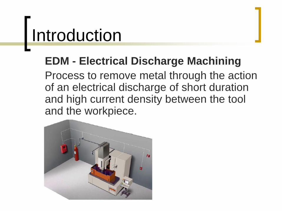
EDM - Electrical Discharge Machining
Process to remove metal through the action of an electrical discharge of short duration and high current density between the tool and the workpiece.
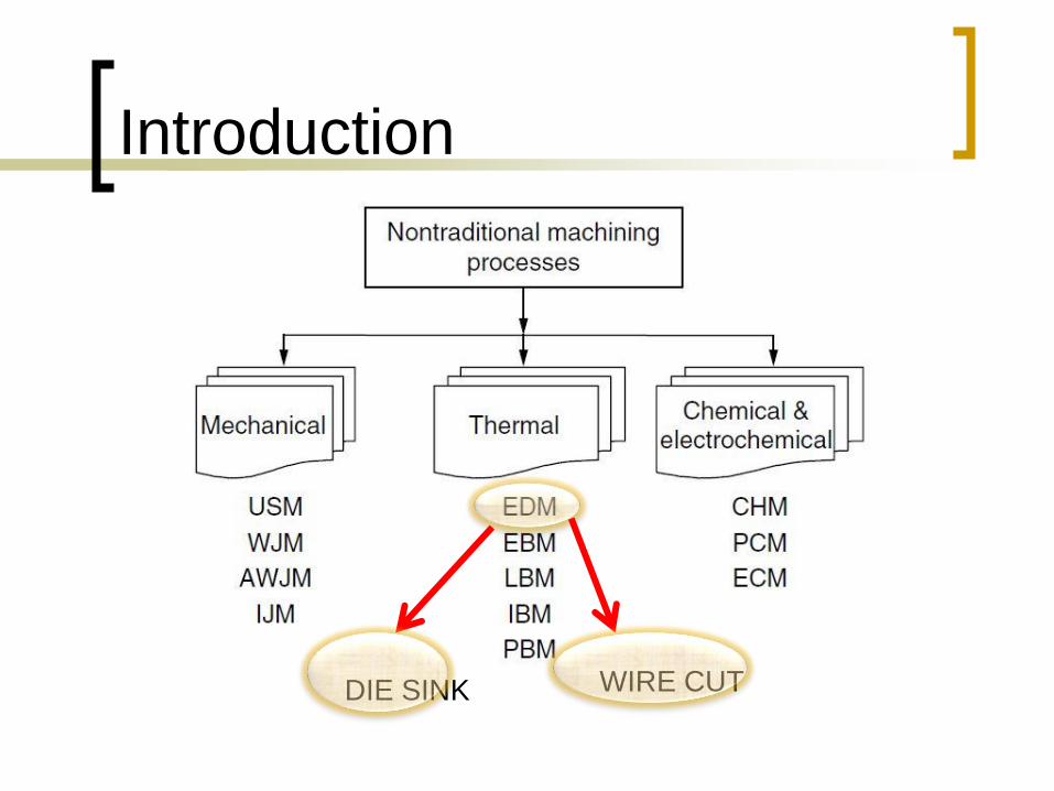
Introduction
DIE SINK WIRE CUT
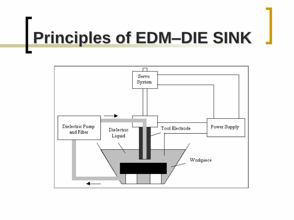
Principles of EDM–DIE SINK
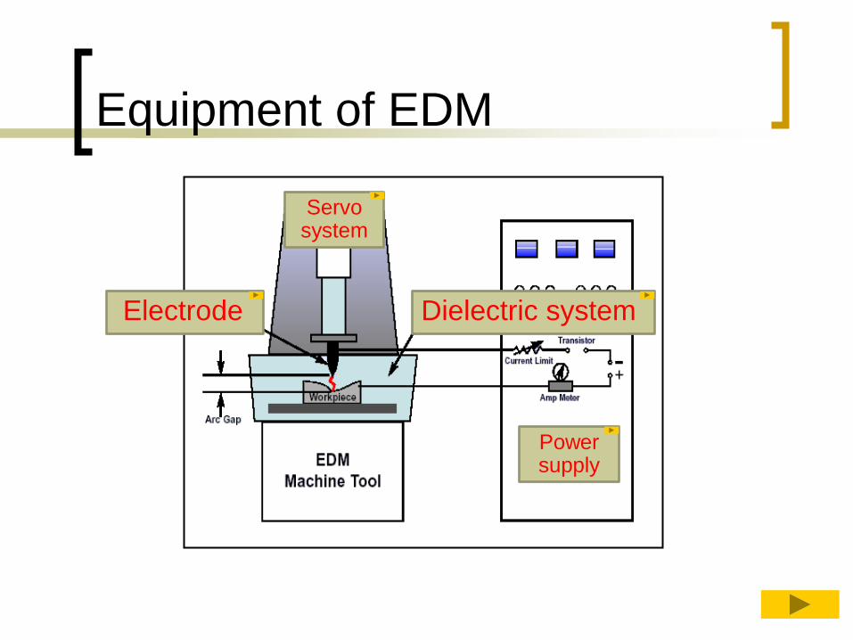
Equipment of EDM
Electrode Dielectric system
Power supply
Servo system
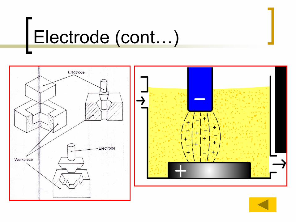
Principles of EDM
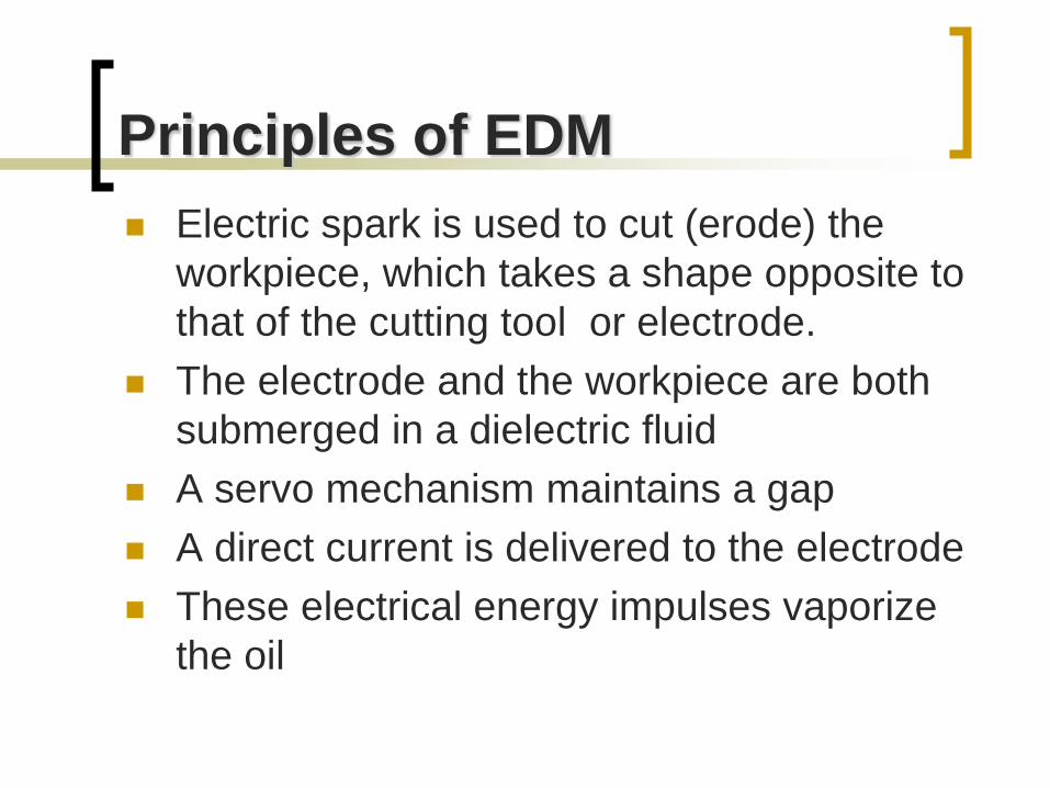
Electric spark is used to cut (erode) the
workpiece, which takes a shape opposite to
that of the cutting tool or electrode.
The electrode and the workpiece are both
submerged in a dielectric fluid
A servo mechanism maintains a gap
A direct current is delivered to the electrode
These electrical energy impulses vaporize
the oil
Principles of EDM (cont..)
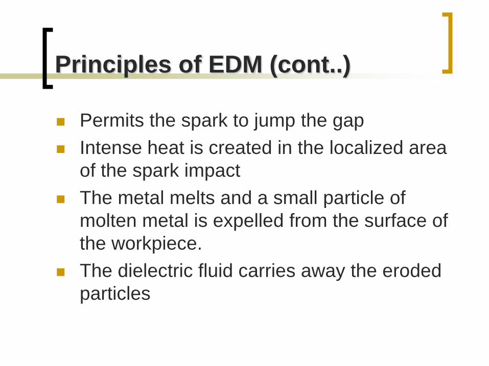
Permits the spark to jump the gap
Intense heat is created in the localized area
of the spark impact
The metal melts and a small particle of
molten metal is expelled from the surface of
the workpiece.
The dielectric fluid carries away the eroded
particles
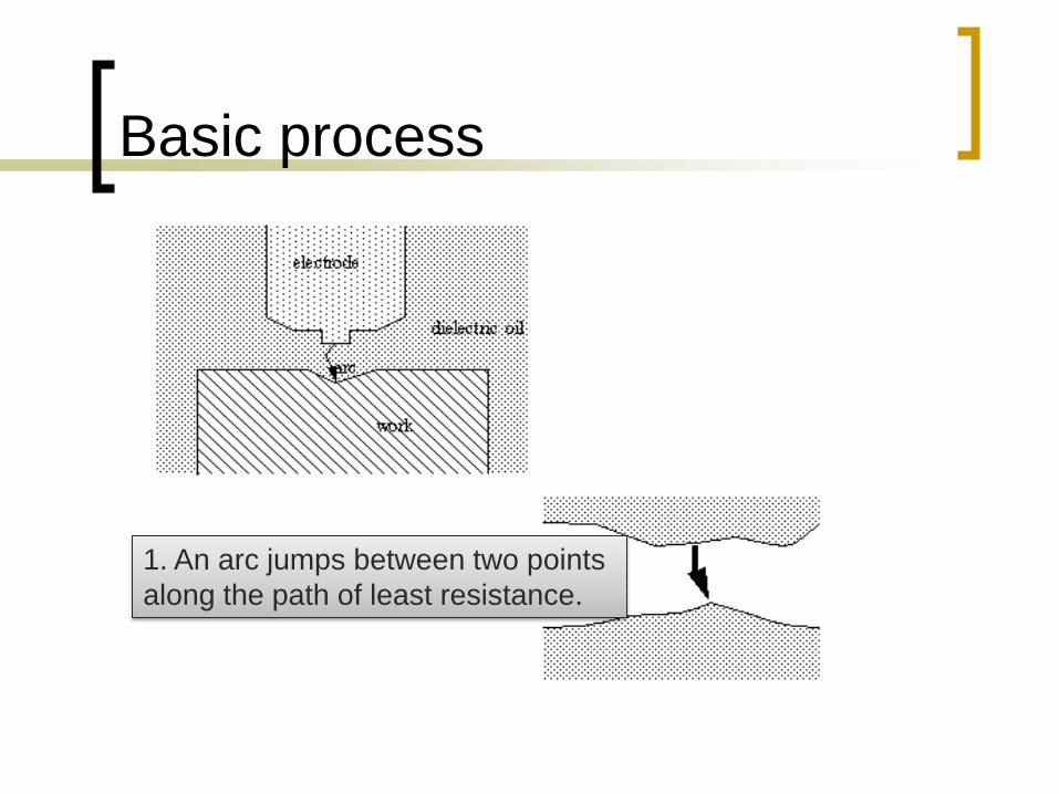
Basic process
1. An arc jumps between two points
along the path of least resistance.
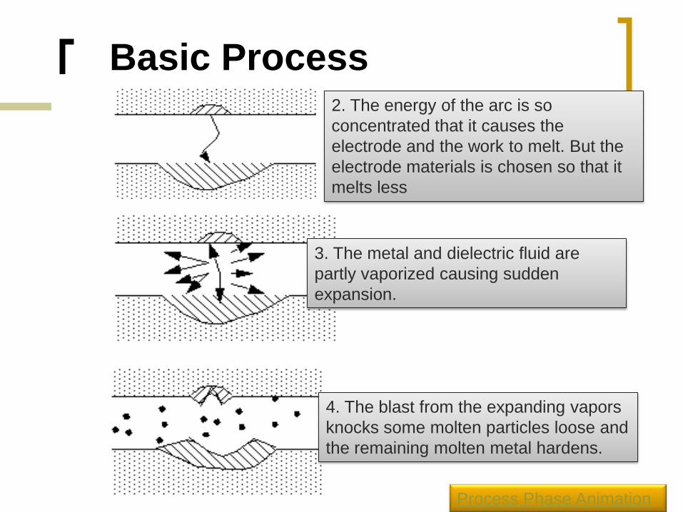
Basic Process 2. The energy of the arc is so
concentrated that it causes the
electrode and the work to melt. But the
electrode materials is chosen so that it
melts less
3. The metal and dielectric fluid are
partly vaporized causing sudden
expansion.
4. The blast from the expanding vapors
knocks some molten particles loose and
the remaining molten metal hardens.
Process Phase Animation
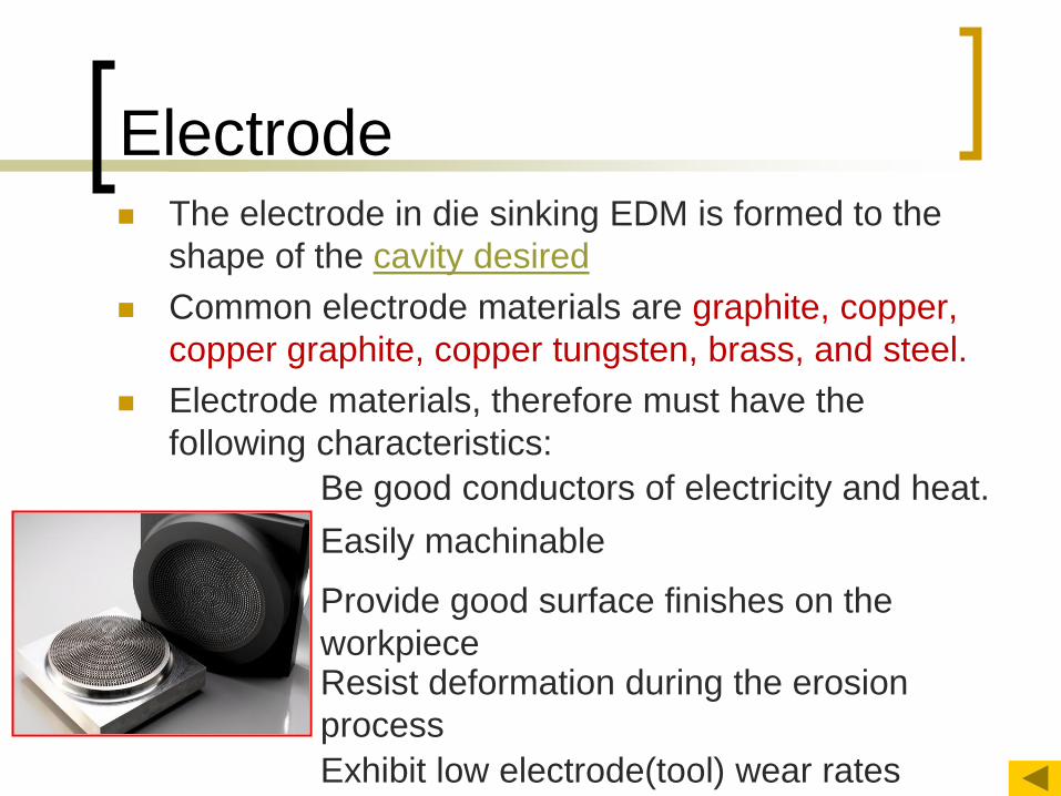
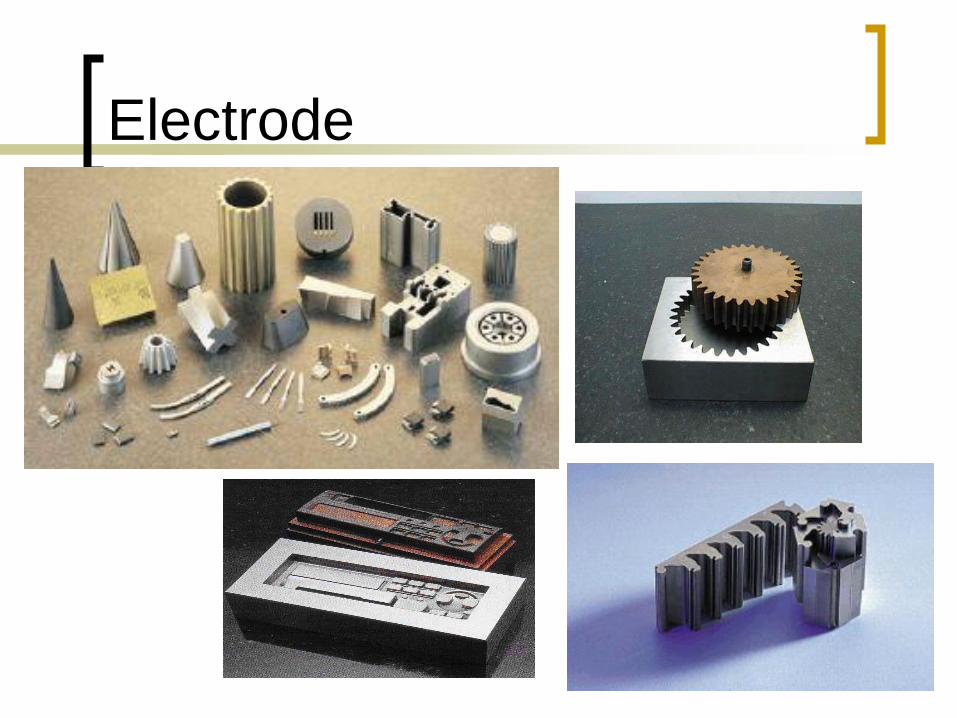
Electrode The electrode in die sinking EDM is formed to the
shape of the cavity desired
Common electrode materials are graphite, copper,
copper graphite, copper tungsten, brass, and steel.
Electrode materials, therefore must have the
following characteristics:
Easily machinable
Be good conductors of electricity and heat.
Provide good surface finishes on the
workpiece Resist deformation during the erosion
process
Exhibit low electrode(tool) wear rates
Electrode (cont…)
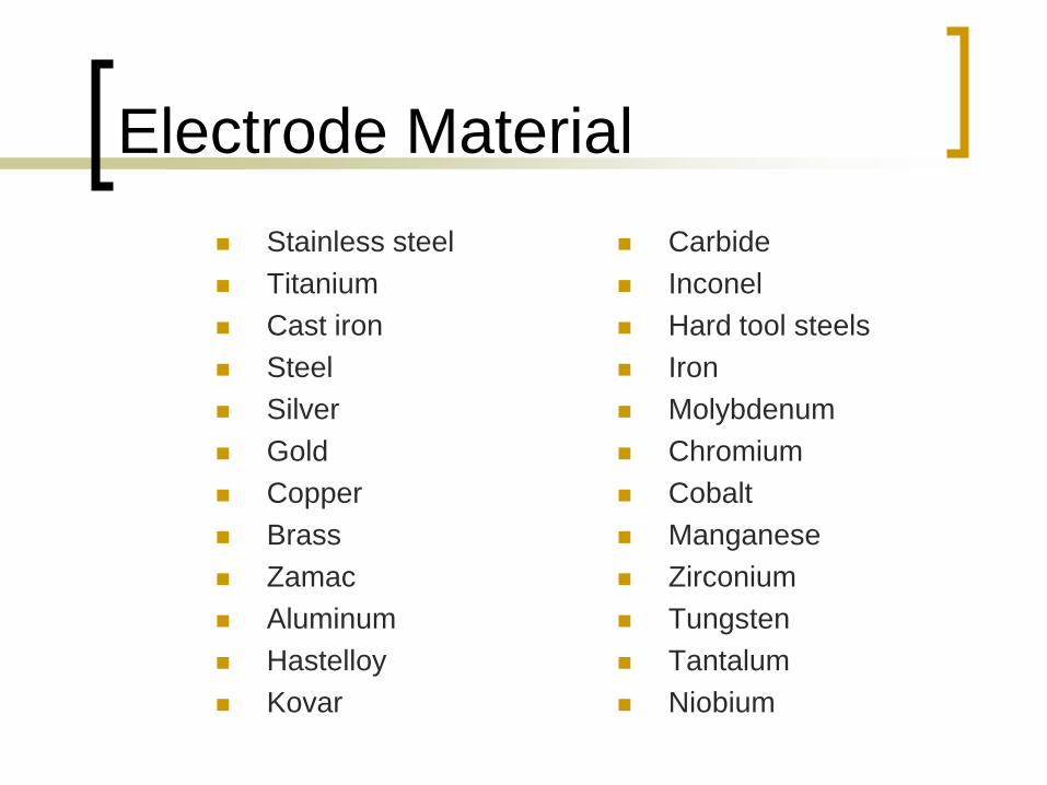
Electrode Material
Stainless steel
Titanium
Cast iron
Steel
Silver
Gold
Copper
Brass
Zamac
Aluminum
Hastelloy
Kovar
Carbide
Inconel
Hard tool steels
Iron
Molybdenum
Chromium
Cobalt
Manganese
Zirconium
Tungsten
Tantalum
Niobium
Electrode
Power supply
Transforms the AC into the pulsed direct current
(DC) to produce the spark discharges at the
machining gap Time-control function that control the length of time
that current flows each pulse
Controls the amount of current allowed to flow
during each pulse (measured in microseconds)
Power supply (cont…)
Phase 1 - Formation of a high-conductivity bridge across the gap
Phase 2 - voltage increase
- formation of a spark channel between the two surfaces
Phase 3 - voltage decrease, current increase
- material melts and vaporizes, a bubble rapidly expands outward
Phase 4 - electrical pulse is terminated, the spark stopped
- explosive expulsion of molten metal, formation of
a small crater in both surfaces
- dielectric fluid remove solidified balls of material
and gas bubbles
Servo System
Automatically maintains a constant gap
between the electrode and the workpiece React by reversing and feeding direction
controlled by the power supply
If the gap is too large, ionization of the dielectric fluid does not occur and machining cannot take place
If the gap is too small, the tool and workpiece may weld together.
Dielectric System
Three functions are performed by the dielectric fluids
a. Insulator between the electrode and the
workpiece
b. Coolant to draw away the small amount of heat
generated by the sparks
c. Flushing medium to remove the metal by-
products from the cutting gap
Dielectric System (Flushing)
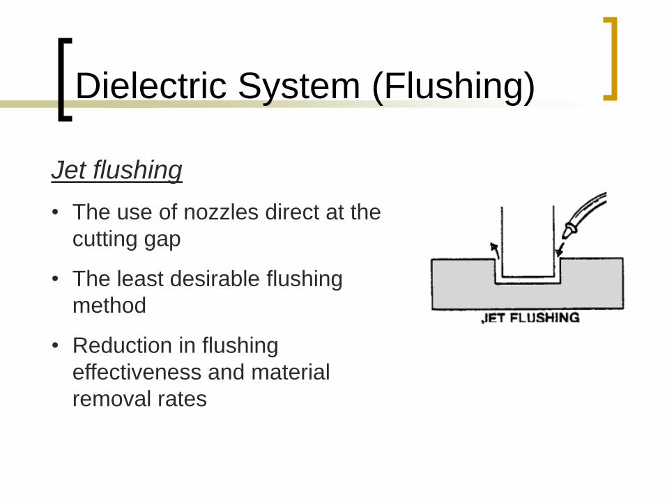
Jet flushing
• The use of nozzles direct at the
cutting gap
• The least desirable flushing
method
• Reduction in flushing
effectiveness and material
removal rates
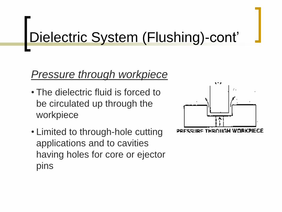
Pressure through workpiece
• The dielectric fluid is forced to
be circulated up through the
workpiece
• Limited to through-hole cutting
applications and to cavities
having holes for core or ejector
pins
Dielectric System (Flushing)-cont’
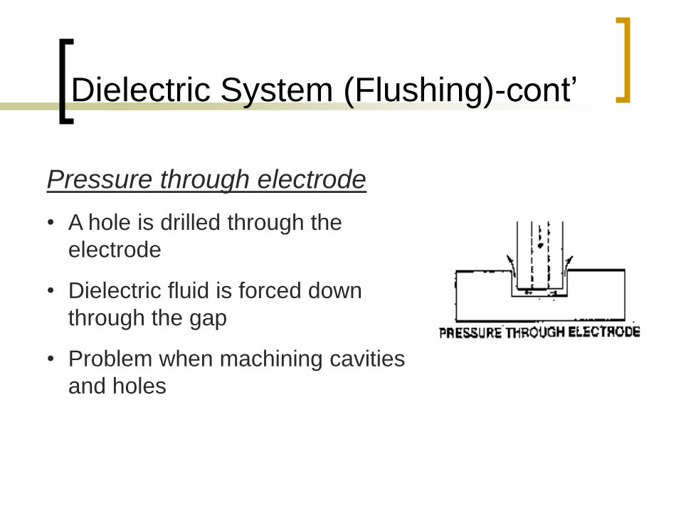
Pressure through electrode
• A hole is drilled through the
electrode
• Dielectric fluid is forced down
through the gap
• Problem when machining cavities
and holes
Dielectric System (Flushing)-cont’
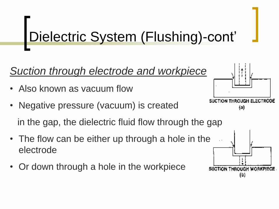
Suction through electrode and workpiece
• Also known as vacuum flow
• Negative pressure (vacuum) is created
in the gap, the dielectric fluid flow through the gap
• The flow can be either up through a hole in the
electrode
• Or down through a hole in the workpiece
Dielectric System (Flushing)-cont’
EDM Process Parameters
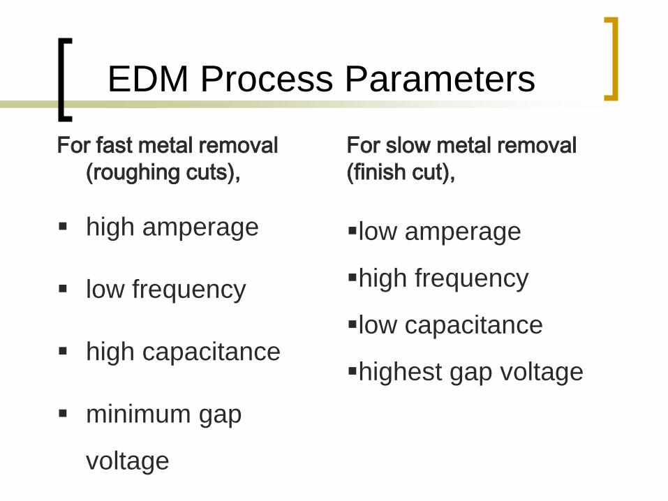
For fast metal removal
(roughing cuts),
high amperage
low frequency
high capacitance
minimum gap
voltage
For slow metal removal
(finish cut),
low amperage
high frequency
low capacitance
highest gap voltage
EDM Process Parameters
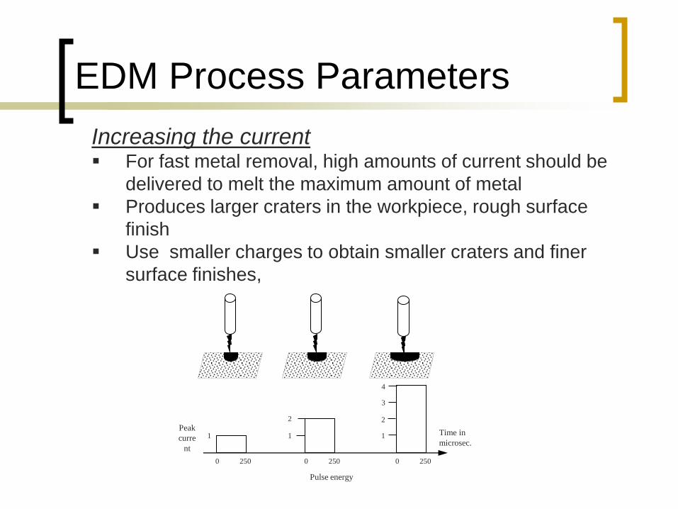
Increasing the current For fast metal removal, high amounts of current should be
delivered to melt the maximum amount of metal
Produces larger craters in the workpiece, rough surface
finish
Use smaller charges to obtain smaller craters and finer
surface finishes,
1
2
0 250
1
0 250
Peak
curre
nt
1
2
3
4
0 250
Time in
microsec.
Pulse energy
EDM Process Parameters
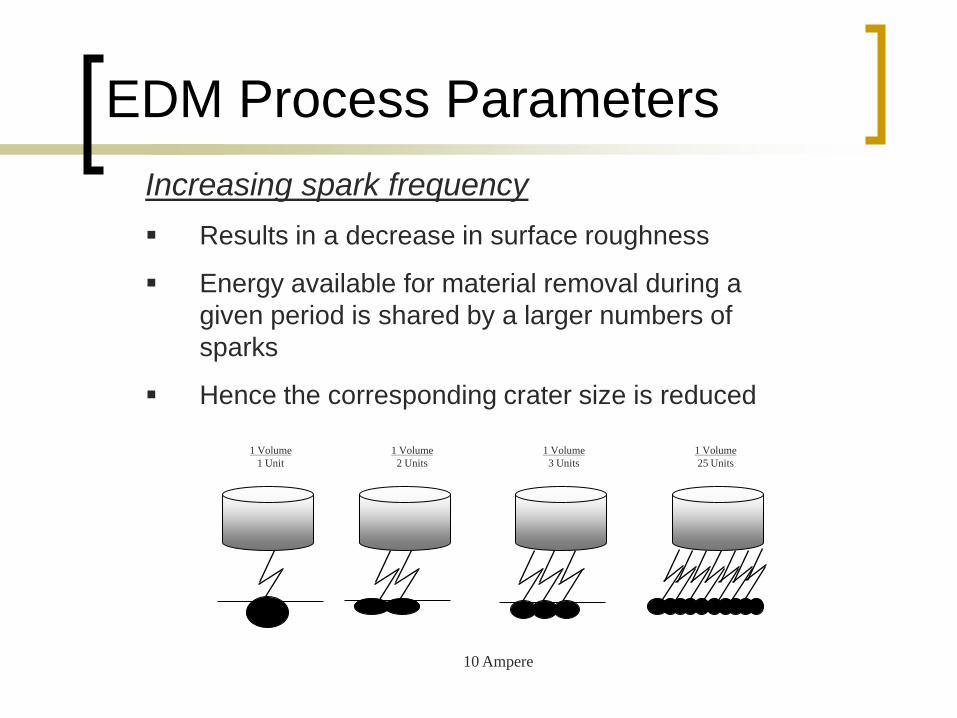
Increasing spark frequency
Results in a decrease in surface roughness
Energy available for material removal during a
given period is shared by a larger numbers of
sparks
Hence the corresponding crater size is reduced
1 Volume
1 Unit
1 Volume
2 Units
1 Volume
3 Units
1 Volume
25 Units
10 Ampere
EDM Process Parameters
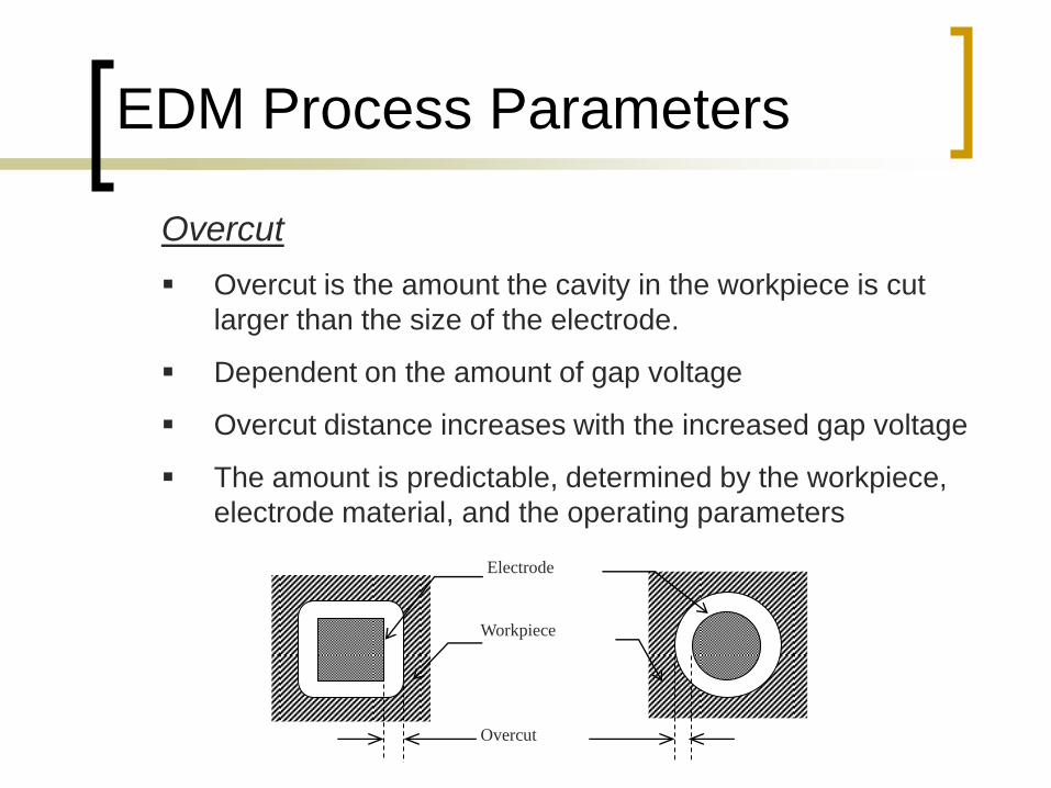
Overcut
Overcut is the amount the cavity in the workpiece is cut
larger than the size of the electrode.
Dependent on the amount of gap voltage
Overcut distance increases with the increased gap voltage
The amount is predictable, determined by the workpiece,
electrode material, and the operating parameters
Electrode
Workpiece
Overcut
EDM Process Parameters
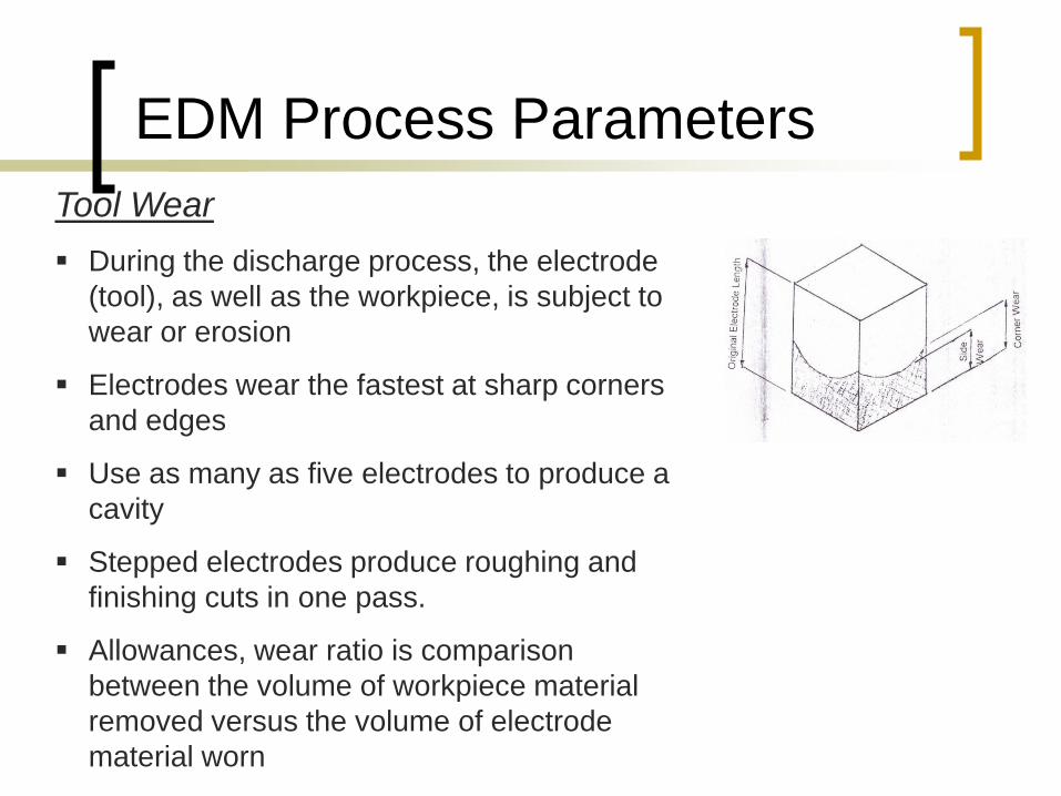
Tool Wear
During the discharge process, the electrode
(tool), as well as the workpiece, is subject to
wear or erosion
Electrodes wear the fastest at sharp corners
and edges
Use as many as five electrodes to produce a
cavity
Stepped electrodes produce roughing and
finishing cuts in one pass.
Allowances, wear ratio is comparison
between the volume of workpiece material
removed versus the volume of electrode
material worn
Material Removal Rate Depends on the amount of energy in each spark
and the number of sparks produced per second.
Rate of metal removal depend on ;
Electrode material – graphit haigher material
removal rates than other electrode.
Workpiece material; more harder material, more
slower material removal rate.
Amount of current in each discharge; higher
current, removes faster
Frequency; more sparks in one second, more
material removed
Dielectric flushing condition ; good flushing will
increase the material removal rate
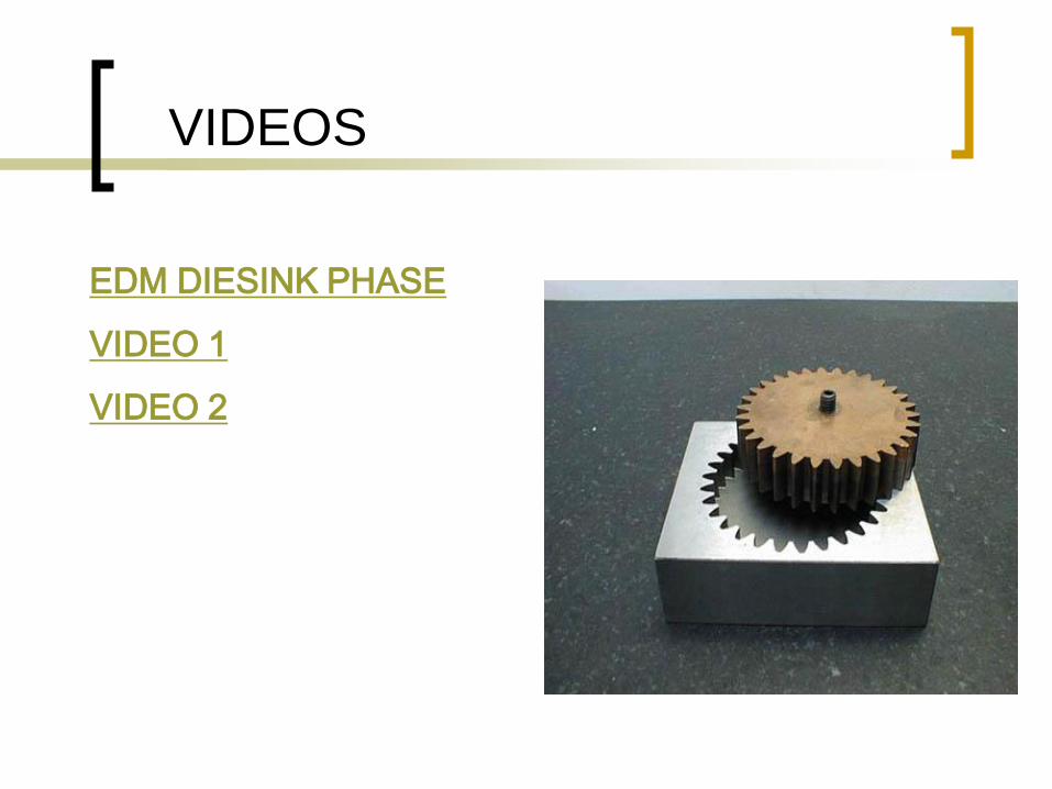
VIDEOS
EDM DIESINK PHASE
VIDEO 1
VIDEO 2

THANK YOU FOR
YOUR ATTENTION