Embed Size (px)
Citation preview
Caprivi Quarantine Camps -C1- Consulting Services Africa
ELECTRICAL BUILDING
PROJECT SPECIFICATIONS
Caprivi Quarantine Camps -C2- Consulting Services Africa
1.1 BUILDING ELECTRICAL INSTALLATION
1.1.1 GENERAL
The contractor may have to open the roofs of existing buildings to install conduit in the ceilings. The contractor will include in his rates for all chasing and making good, where chasing of walls were done or holes were drilled through walls. All work will be to SANS 10142.
1.1.2 DRAWINGS
Installation details are provided on relevant drawings and should be adhered to.
1.1.3 CABLES
All cables shall be unrolled, handled, laid, supported, etc. in accordance with the manufacturer’s recommendations.
All polyvinyl chloride insulated cables (PVC/PVC/SWA/PVC and other) shall be single steel wire armoured and shall be served overall with a final layer of polyvinyl chloride.
Cables laid in ground shall be in trenches to a depth as specified and shall be bedded in and enclosed in clean river sand 75 mm all round before backfilling commences. Ends of all PVC/PVC/SWA/PVC cables shall be made off (terminated) with a suitable gland complete with neoprene shroud, effectively earthed with armouring clamped between substantial tapered bushes and bolted to equipment or switchboards. All mechanical cable glands shall be of the captive cone type. No joints in cable runs will be allowed except under exceptional circumstances and then only as specifically approved by the Engineer.
When more than one cable is laid in the same trench, they shall be laid parallel to one another not less than 40 mm apart.
All trenching and excavation shall be reinstated to the original condition by mechanical compaction in 150 mm layers and the Contractor shall be responsible for the making good of any settlement.
Red and white cable marking tape, 150 mm wide, shall be laid at a depth as specified below ground level above each cable. In the case of HT cables, PVC or concrete cable tiles shall be laid at a depth as specified below ground level above the cable/cables.
Approved concrete cable route markers shall be installed at each point where the installed cable changes direction and at intervals along the cable route as specified.
1.1.4 DISTRIBUTION BOARDS
1.1.4.1 General At installations with a meter and main board and secondary boards, the meter and main boards shall be equipped with control equipment of at least 5 kA short circuit capacity.
Secondary DB's will be equipped with 2,5 kA control equipment. All openings in DB's will be sealed, to ensure that wasps shall not enter.
Boards shall be properly protected at all times until final hand over to prevent damage during construction. Any damage shall be made good to the entire satisfaction of the Engineer.
Doors to distribution boards shall be suitably braced, on heavy duty “lift-off” hinges and shall be fitted with approved spring catches without locks.
Removable front panels shall be secured by means of quick release fasteners and front panels carrying instruments shall be hinged in addition. Where nuts are visible, chromium plated dome head nuts shall be used.

Caprivi Quarantine Camps -C3- Consulting Services Africa
1.1.4.2 General Construction All switchboards shall be of ample size to accommodate the specified switchgear and provide space for future switchgear. Main and sub-distribution boards shall be robustly constructed of galvanized sheet steel of not less than 1,5 mm. The boards shall be fully equipped with the requisite number of circuit breakers, earth leakage device/s, insulated neutral bar/s and earthing bar mounted behind a removable cover plate through which switch toggles are to protrude.
All boards shall be completely vermin proof.
Conduit bushings leaving the DB's at the top will be sealed with silicone to ensure the DB's are water tight.
Where distribution boards are to be built into walls they shall be equipped with an adjustable mild steel shroud to compensate for any irregularities in mounting, plaster thickness or tray position.
The internal surfaces of all distribution boards shall be painted with two coats of best quality “arc-free” paint and the external surfaces shall be properly treated and coated with an approved epoxy/polyester baked powder coating of a colour to be approved by the Architect.
1.1.4.3 Load Balance Loads shall be balanced as evenly as possible across the phases to the entire satisfaction of the Engineer before final acceptance.
1.1.4.4 Labelling Care shall be taken to ensure that all equipment is fully labelled and that accurate descriptions and safety warning notices appear in English only. The Engineer must be approached by the Contractor to obtain the specific requirements for labels before the labels are manufactured.
All circuits and functions shall be properly and clearly identified.
All labels used shall be engraved trafolite with black letters on a white background for all normal labels and red letters on a white background for all danger notices.
The main isolating switches shall be clearly labelled in accordance with the regulations and the size and origin of all supply cables and busbars shall be clearly labelled, as must all equipment situated inside the board, indicating function, circuit controlled, fuse rating, etc.
A legend card, covered by removable 2 mm thick transparent acrylic plastic panel, shall be installed on the inside of the door of the distribution boards or cubicles and circuits shall be designated on this card. All other equipment shall be individually labelled, indicating function. All plates shall be fixed to panels by means of screws or channelling.
All other equipment including meters, instruments, indicator lights, switches, push buttons, circuit breakers, fuses, contactors, control relays, protection relays, etc., shall be identified. The function of the equipment and circuits shall be clearly indicated. The main switch shall be labelled as such and designated :
"MAIN SWITCH : SWITCH OFF IN CASE OF EMERGENCY"
Flush mounted equipment within doors or front panels shall be identified with labels fixed to the doors or front panels respectively.
The labels for equipment installed behind panels, shall be fixed to the chassis close to the equipment. If this equipment is positioned too close together to accommodate descriptive engraved labels, the equipment may be identified by a code or number on an engraved label which shall be fixed close to the equipment. The code number shall be identified on a legend card which shall be installed on the switchboard behind a plastic or other protective cover.

Caprivi Quarantine Camps -C4- Consulting Services Africa
1.1.4.5 Busbars The current density of busbars shall not exceed 1,5 A/mm² copper and busbars shall be designed to withstand the mechanical and thermal stresses under short circuit conditions without deformation taking place or parts breaking. Busbars shall be mounted on porcelain or other approved stand-off insulators with the phases correctly colour coded. Aluminium busbars will not be accepted. Neutral bars shall have a cross-section of at least 6,3 x 25 mm and shall be long enough for the lugs of all neutral conductors to be connected separately to the busbar without overlapping the lugs.
Spacing of busbars shall be not less than 50 mm and neutral busbars must be of the same cross-section as the phase bars.
A suitable solid copper earth bar with sufficient ways including 30% spare ways shall be provided near the cable entry gland tray and shall be easily accessible.
All internal wiring shall be carried out with PVC insulated stranded copper conductors of adequate size and of a colour corresponding to the relevant phase. Conductors shall be neatly led in vertical or horizontal rows and bound with trimmed cable ties. No joints will be allowed in internal wiring.
1.1.4.6 Circuit Breakers or Main Switches Circuit breakers shall comply with SANS 156.
Contacts of circuit breakers shall be silver alloy and shall close with a high pressure wiping action.
Where specified, the circuit breaker shall be capable of accommodating factory fitted shunt trip or auxiliary contact units or similar equipment.
The operating handle shall provide clear indication of "ON", "OFF" and "TRIP" positions.
The mechanism shall be of the TRIP-FREE type preventing the unit from being held in the ON position under overload conditions.
All circuit breakers in a particular installation shall as far as is practical be supplied by a single manufacturer.
The incoming terminals of single-pole miniature circuit breakers shall be suitable for connection to a common busbar.
The circuit breaker shall have a rating plate indicating the current rating, voltage rating and breaking capacity.
When checking for proper operation the main switch or circuit breaker must be switched ON and OFF and voltage measurements taken on the outgoing side in both cases to check that all three poles switch properly and that the supply to the switchgear is OFF when the main switch or circuit breaker is switched OFF.
All moulded case circuit breakers shall be of flush panel mounting and with inverse current time delay overload and instantaneous short circuit characteristics. Mechanically coupled single-pole circuit breakers used as double or triple-pole circuit breakers are not acceptable unless overload releases are internally coupled. The fault current rating shall be as specified.
Space shall be provided in each board for at least 30% but not less than three additional single phase breakers. When spare capacity for future circuit breakers is called for, escutcheon blanks shall be used and not blank-off covers.
Triple, double and single-pole switches shall be capable of breaking the full load and closing on to a full system fault. The fault current rating shall be specified.
1.1.4.7 Isolators Isolators used as main switches for boards shall comply in principle with requirements of the previous paragraphs above.
Isolators shall be suitably rated for the continuous carrying, making and breaking of the rated current specified as well as the through-fault current capacity as specified.
Caprivi Quarantine Camps -C5- Consulting Services Africa
To distinguish isolator switches from circuit-breakers the operating handles shall have a distinctive colour and/or the switch shall be clearly and indelibly labelled "ISOLATOR".
1.1.4.8 Contactors and Relays All contactors and relays shall comply with BS5424 and shall be able to withstand the maximum prospective fault current that can occur at the point where the contactor or relay is installed. All contactors unless otherwise specified shall have two normally open and two normally closed auxiliary contacts spare of 10 A rating.
1.1.4.9 Earth Leakage Protection Earth leakage protection units shall be suitable for operation at the system voltage, shall have test push buttons and unless otherwise specified shall have a sensitivity of 30 mA maximum. Earth leakage protection units shall not incorporate overcurrent protection.
Earth leakage relays shall be single or three-phase units for use on 220/250 Volt single phase or 380/433 Volt three-phase, 50 Hz, supplies.
The units shall be suitable for installation in switchboards in clip-in trays or bolted to the chassis.
The earth leakage relay shall function on the current balance principle and shall comply with SANS 767 as amended, and shall bear the SABS/SANS mark. Integral test facilities shall be incorporated in the unit.
1.1.4.10 Time Switches Time switches shall be suitable for operation at the system voltage with silver to silver or other approved contacts rated at not less than 10 A with an electrically wound clockwork or battery reserve of eight hours minimum and shall have the following features :
Daily programmable with minimum 30 minute “on” and “off” control segments;
Weekly programmable with day omission segments of minimum 12 hours, i.e. mornings or afternoons;
A clock face dial with hour and minute hands, or a LCD display for electronic timers.
1.1.4.11 Lightning Arresters Lightning arresters to SANS 60099 shall be provided for each phase and neutral in all distribution boards.
1.1.5 TRUNKING AND POWER SKIRTING
Trunking and power skirting shall comply with SANS 61084.
Trunking wiring channels shall be plastic, aluminium or galvanized mild steel rolled lipped channels fixed as specified. All cut ends of metal trunking shall be filed smooth and touched up with an approved zinc-rich cold galvanizing paint.
Power skirting shall be two or three compartment trunking fixed as specified.
Trunking wiring channels shall be galvanised mid steel, plastic or aluminium, with covers and fixed as specified.
1.1.6 WIRING
1.1.6.1 General Wiring practices shall comply with SANS 10142 in all respects.
For wiring in partition walls SURFIX Cables can be used instead of conduit wiring.
1.1.6.2 Type of Conductors PVC-insulated, stranded copper conductors and bare stranded or green PVC-insulated copper earth conductors complying with the materials specification shall be used exclusively. Only
Caprivi Quarantine Camps -C6- Consulting Services Africa
where cables are specified or in instances where the exceptions stipulated in SANS 10142 are applicable, may the Contractor deviate from this requirement.
1.1.6.3 Size of Conductors Where conductors sizes are not specified, the following minimum conductor sizes shall be used :
Lighting circuits : 2,5 mm2 live and neutral conductors, 2,5 mm
2 copper earth
conductor
Socket-outlet circuits : 4,0 mm2 live and neutral conductors, 2,5 mm
2 copper earth
conductor
Stove, air-conditioning and geyser circuits
: 6,0 mm2 live and neutral conductors 4,0 mm
2 copper earth
conductor
All earth continuity conductors laid with cables shall be bare stranded copper conductors and all other earth continuity conductors shall be PVC insulated stranded copper conductors, unless specified otherwise.
Extreme care shall be taken not to apply excessive mechanical tension to PVC insulated conductors when drawing conductors into conduits or wireways and care shall also be taken not to draw PVC insulated conductors around sharp corners or protruding surfaces in conduits.
PVC insulated conductors shall be lubricated with high quality French chalk before they are drawn into conduit. The use of lubricating oil for drawing in PVC insulated conductors is not permitted. Conductors between an isolator and appliance shall be of the same cross-sectional area as the conductors fed to the isolator and shall, where necessary, be in flexible metal conduit. Wiring between isolators and fixed heating appliance terminals shall be in silicone rubber insulated conductors.
Wiring installed in wiring channels or power skirting shall be installed in the correct compartment to prevent any cross-overs and shall be bound together in groups not exceeding ten conductors by means of approved straps at spacings not exceeding 1 m. No joints will be permitted in wiring.
Circuit wiring shall be of the loop-in system, and not more than four conductor ends will be allowed at any one termination point. Cutting away of wire strands of any cable will not be allowed and no jointing of conductors in draw boxes or the cutting away of insulation is permissible. Where joints are used, they shall be in heavy brass terminals with porcelain insulators.
Circuits for different services, e.g. lighting circuits, power circuits, intercommunication circuits and telephone circuits, shall each be routed in separate conduit runs.
A neutral conductor, equal in size to the phase conductors, shall be run to each three-phase outlet unless otherwise specified.
Joints will not be permitted in individual conductors forming part of any circuit.
1.1.7 WIREWAYS
All unarmoured conductors shall be installed in conduits, cable channels (trunking) or power skirting and shall under no circumstances be exposed. Cable channels and power skirting shall be of metal construction unless specifically approved to the contrary.
Contractors must note that common wireways will only be permitted for relatively light current-carrying conductors such as lighting and socket-outlet circuits. Heavy current-carrying conductors such as feeders to distribution boards and large power points, must be installed in separate conduits or wireways.

Caprivi Quarantine Camps -C7- Consulting Services Africa
1.1.8 GROUPING OF CONDUCTORS
In cases where the conductors of more than one circuit are installed in the same wireway, the conductors of each separate circuit (including earth conductor) shall be taped at intervals of 1 m with PVC tape.
Conductors entering switchboards or control boards shall be grouped and bound by means of plastic cable ties and not with PVC insulation tape.
1.1.9 CONDUITS AND ACCESSORIES
1.1.9.1 Conduit Systems Conduit systems shall comply with SANS 60614 and SANS 61035.
Plain-end metallic conduit (black enamelled or galvanised mild steel) such as 'CHENEY', 'EASILOCK' and 'LOCFIT or similar conduit systems shall be used for surface-mounted exposed conduit. PVC conduit shall be used only under plaster.
Plain-end conduit and associated accessories shall be manufactured of mild steel having a minimum thickness of 0,9 mm. Conduit manufactured of lighter gauge material will not be permitted.
1.1.9.2 Conduit Installation Conduits may be installed as follows :
i) Open and closed roof spaces
Galvanised mild steel conduit shall be used in exposed ceiling spaces. Black enamelled conduit may be used in enclosed ceiling spaces.
ii) Walls, slabs etc
Galvanised mild steel conduit shall be used in surface mounted applications.
iii) Chased into walls
PVC conduit may be used where it can be chased into walls.
iv) Conduits cast into concrete shall be securely fixed in position before pouring commences.
1.1.9.3 Installation Requirements i) Position of outlets
All accessories such as boxes for socket-outlets, switches, lights, etc. shall be accurately positioned and shall be installed level and square, at the correct height from the floor, ceiling or roof level and in the correct position relative to building lines and equipment positions.
ii) Cover plates Cover plates, either as part of the switch or socket assembly or with blank cover plates if unused shall be provided for all draw- and wall boxes. Blank cover plates shall match other cover plates in the same area.
iii) Draw-wires Galvanised steel draw-wires shall be provided in all unwired conduits for future
extensions, telephone installations and other services.
iv) Draw boxes
Draw boxes shall be installed at intervals not exceeding 15 m in straight runs.
v) Bends Manual cold bends of conduit of nominal size up to and including 25 mm is permitted, provided that the radius of the bend exceeds six times the nominal size of the conduit, with the external angle of the bend not exceeding 90°. In all other cases bends shall consist of suitable accessories. Bends shall comply with SANS 10142.
Caprivi Quarantine Camps -C8- Consulting Services Africa
Bending and setting of plain-end conduit must be done with special benders and apparatus manufactured for this purpose and which are obtainable from the suppliers of the system. Damaged conduit resulting from the use of incorrect bending apparatus shall be completely removed and any wiring already drawn into such damaged conduits shall be completely renewed at the Contractor's expense.
A maximum of two 90° bends or the equivalent displacement will be allowed between outlets and / or boxes. All bends shall be made without heating the conduit or without reducing the diameter of the conduit. Inside radii of bends shall not be less than five times the outside diameter of the conduit (refer to SANS 10142).
vi) Wall socket-outlets Where more than one outlet point is to be connected to the same circuit, the conduit
shall continue directly to the next position from the previous outlet box on the same circuit. Where metal trunking is used, the conduit may be installed from the trunking directly to the outlet box.
vii) Lighting points Round drawboxes shall be [rovided for all lighting points. Where luminaires are
to be fixed directly to the pendant box, the pendant box shall be fixed independently of the conduit installation.
viii) Access holes All access holes in draw-boxes or other conduit accessories shall be securely
blanked off by means of brass plugs to render the installation vermin proof.
1.1.9.4 Terminations i) Conduit ends Conduit ends shall be cut at right angles to ensure that ends butt squarely at joints.
Threads shall not be visible at joints and connections except at running joints. The total length of the thread on the two conduit ends shall not exceed the length of the coupling.
ii) Joints Joints shall be kept to a minimum. All conduit ends shall be reamed and all joints
tightly screwed or glued. Only approved couplings shall be used.
iii) Connections Conduits shall be connected directly to draw-boxes with spouted connections.
Conduits shall be screwed tightly home and no threads shall be visible.
iv) Continuity Mechanical and electrical continuity shall be maintained throughout the conduit
installation.
v) Switchboards, power skirting, etc. Conduits shall be terminated by means of a brass female bush and two locknuts in
pressed steel switchboards and distribution boxes, cable ducts, power skirting, etc. The conduit end shall only protrude far enough through the entry hole to accommodate the bush and locknut.
vi) Draw boxes and outlet points A female bush and two locknuts shall be used to terminate conduits at draw boxes
and outlet boxes without spouts. Where space permits, a coupling, brass male bush and locknut may be used with sufficient allowance for the reduction of the internal diameter by the male bush.
vii) Bush-nuts Bush-nuts for the connection of earth conductors to conduits are not acceptable.
vii) Screws, bolts and nuts
Caprivi Quarantine Camps -C9- Consulting Services Africa
Steel locknuts of thick gauge steel with milled sides shall be used in all cases. Cadmium-plated bolts and nuts shall be used except in cases where the installation is exposed to the weather, where brass bolts and nuts shall be used.
Screws shall be installed in all tapped holes in fittings and accessories and shall be completely screwed in to prevent damage to the screw thread by concrete or plaster.
1.1.9.5 Debris Care shall be taken to prevent debris or moisture from entering conduits during and after installation. Conduit ends shall be sealed by means of a solid plug which shall be screwed to the conduit end. Conduits shall be cleaned and swabbed to remove oil, moisture or other debris that may be present before conductors are installed. Swabs shall not be attached to the conductors.
1.1.9.6 Defects Each length of conduit shall be inspected for defects prior to installation, and all burrs shall be removed. Split, dented or otherwise damaged conduits, or conduits with sharp internal edges shall not be used and shall be removed from site. Conduits shall not be blocked by foreign media during or after installation.
1.1.9.7 Withdrawal of Conductors To ensure that all electrical conductors are easily withdrawable from conduits and to ensure that there are no joints in the conductors, the Engineer's representative will have the right to have the conductors of any circuit removed for inspection at his discretion. If the conductors are found to be in a satisfactory condition after having been withdrawn, the Employer shall bear the cost of withdrawing and re-installing such conductors. Conductors found to have been damaged during installation or removal, or found with joints, shall be replaced and the cost shall be borne by the Contractor.
1.1.9.8 Surface Installations i) Appearance All conduits shall be installed horizontally or vertically as determined by the route
and the Contractor shall take all measures to ensure a neat installation.
Where conduits are to be installed directly alongside door frames, beams, etc. that are not true, conduits shall be installed parallel to the frames, beams, etc.
All labels shall be removed from surface mounted conduit.
ii) Saddles Conduits shall be firmly secured by means of saddles and screws and in accordance
with SANS 10142. Where saddles are used to secure vertical lengths of conduit connected to surface mounted switch boxes or socket-outlet boxes, the saddles shall be spaced so that the intervals between the box and the first saddle, between any two successive saddles and between the last saddle and the ceiling or roof are equidistant. Conduits shall be secured within 150 mm before and after each 90° bend and within 100 mm of each outlet box.
ii) Joints Joints will only be allowed in surface conduit lengths exceeding 3,5 m. Threads
shall not be visible at joints of completed installations, except where running joints are used. Running joints will be allowed only when absolutely necessary. All running joints shall be provided with locknuts.
iii) Accessories Inspection bends or tee pieces shall be used. Non-inspection type bends may be
used in the case of 32 mm or 50 mm diameter conduits. All draw-boxes supporting luminaires or other equipment shall be fixed independently of the conduit installation.
iv) Offsets
Caprivi Quarantine Camps -C10- Consulting Services Africa
Where an offset is required at conduit terminations or cross-overs, the conduit shall be saddled at the offset.
vi) Cross-over Conduit routes shall be carefully planned to avoid cross-overs. Where cross-overs
are unavoidable, one conduit only shall be offset to cross the other. Cross-overs shall be as short as possible and shall be uniform. Alternatively, cross-overs shall be installed in purpose-made boxes. This method shall be employed on face brick walls and in other circumstances where required by the Engineer.
vii) Parallel conduit Parallel conduit runs shall be equidistant and saddles shall be installed in line.
Alternatively, a special clamp may be used to secure all conduits in unison. In the case of conduits of different diameters, the latter method shall only be used if a purpose-made clamp designed to accommodate the various conduit sizes, is provided.
viii) Painting of conduit Visible runs of surface-mount conduit shall be galvanised except where otherwise
approved, in which case surface mounted visible black conduitsshall be painted in the same colour as the wall.
ix) Boxes Where surface mounted switches or socket-outlets are installed indoors ivory
coloured epoxy coated pressed steel or PVC surface boxes shall be used.
1.1.9.9 Conduit Installations in Roof Spaces The conduit shall be installed in the ceiling spaces of buildings that have ceilings. Where these ceiling spaces can only be accessed by removing the roof panels; the Contractor shall take this into account when calculating his rates.
In buildings that do not have ceilings the conduit shall be installed along the wall plates and roof trusses and beams to the various light points, and vertically down the walls to the light switches and socket outlets. Installation of conduits suspended between the rafters will not be permitted.
Conduit in roof spaces shall be installed parallel or at right angles to the roof members and shall be secured at intervals not exceeding 1.5 m by means of saddles screwed to the roof timbers.
Nails or crampets will not be allowed.
Under flat roofs in false ceilings, or where there is less than 900 mm clearance, or in instances where the ceilings are insulated with glasswool or other insulating material impeding access, the conduit shall be installed in a manner which allows for wiring from below the ceilings.
Conduit runs from switchboards shall terminate in fabricated sheet steel draw-boxes installed directly above or in close proximity to the boards.
Spare conduits covering the total number of spare ways on switchboards, shall be provided between the boards and the roof draw-box.
As an alternative to above, a trunking channel that can accommodate all circuits may be installed from the switchboard to the roof space, provided that where the circuits enter the various conduits in the roof space, the conduits shall be terminated on the trunking channel with bushes or grommets to prevent damage to the conductors.
1.1.9.10 Fixing to Walls Only approved plugging materials such a fibre plugs or plastic plugs, etc., and roundhead screws shall be used when fixing saddles, switches, plugs etc. to walls. Wooden plugs are not acceptable nor should plugs be installed in joints in brick walls.
Caprivi Quarantine Camps -C11- Consulting Services Africa
1.1.9.11 Future Extensions i) Open roof spaces Conduits intended for future switches and socket-outlets, shall terminate 40 mm
above the tie beams in roof spaces with more than 900 mm free space. The conduit ends shall be threaded and fitted with a coupling and brass plug.
ii) Cover plates Unused boxes for switches and socket-outlets shall be covered with metal cover
plates. Unused boxes for luminaires shall be covered with round galvanised metal cover plates which fit tightly against the finished surface.
1.1.9.12 Expansion Joints Where conduits cross expansion joints in the structure, approved draw-boxes providing flexible connections in the conduit installation shall be installed.
The draw-box shall be installed adjacent to the expansion joint of the structure and a conduit sleeve, one size larger than that specified for the circuit, shall be provided on the side of the draw-box nearest the joint. The one end of the sleeve shall terminate at the edge of the joint and the other shall be secured to the draw-box by means of lockouts.
The circuit conduit passing through the sleeve shall be terminated 40 mm inside the draw-box and in the case of metallic conduit, the conduit end shall be fitted with a brass bush. The gap between the sleeve and the conduit at the joint shall be sealed with 'Pratley Tic-Tac', silicone or equal sealing compound, to prevent the ingress of dirt. In the case of metallic conduit, an earth clip shall be fitted to the conduit projection inside the draw-box and the conduit bonded to the box by means of 2.5 mm
2 bare copper earth wire and a brass bolt and
nut.
The end of the other circuit conduit shall be secured to the draw-box by means of locknuts and a brass bush in the case of screwed metallic conduit or a standard bushed adaptor for other conduit types.
In the case of metallic conduit, a 2,5 mm2 bare copper wire shall be installed between the
first conduit boxes on either side of the joint, in addition to an earth wire which may be specified for the circuit. The conduit boxes shall be drilled and tapped and the earth wire shall be bonded to the boxes by means of lugs and brass screws.
Where a number of conduits are installed in parallel they shall cross the expansion joint of the structure via a single draw-box. A number of draw-boxes adjacent to each other will not be allowed.
1.1.9.13 Other Services Conduits may not be installed closer than 150 mm to pipes of other services such as gas, steam, hot water or other materials which may damage the conduits or conductors. To prevent electrolytic corrosion, conduits shall not touch other pipe installations.
Conductors may not be drawn into conduits before the conduiting has been inspected and approved by the Engineer.
All conduit for communications services shall have draw wires as specified drawn in and left inside the conduits for future use.
All conduits shall be bushed and secured by lock-nuts to distribution boards, wall boxes, etc.
Spare conduits (10% with a minimum of two 20 mm and one 25 mm conduits) shall be run from the distribution boards into the roof space to cater for future circuits.
1.1.10 SWITCHES AND SOCKET OUTLETS
1.1.10.1 General All switches and switched socket outlets shall be of approved manufacture to SANS 60669.
Weatherproof switches shall be of quick make and break type with porcelain boxes in robust brass or galvanized cast iron cases with machined joints or in plastic or aluminium cases.

Caprivi Quarantine Camps -C12- Consulting Services Africa
All switches and switched socket outlets of the domestic or industrial type shall be rated for 250 Volt 16 Ampere. Cover plates shall be metal. RED indicator dots on switches shall indicate the “ON” position.
Three phase socket outlets shall be of the CEE-17, 380V, 6 h pattern with five contact tubes incorporating an interlocked switch and shall be rated at 32 A.
1.1.11 SOCKET OUTLETS
1.1.11.1 Mounting height Unless specified to the contrary, socket-outlets shall be installed at the following heights above finished floor level, measured to the centre of the outlet:
In general : 300 mm
Showroom, shops : 1 400 mm
Domestic kitchens, tea kitchens and laboratories
: 1 200 mm
Commercial kitchens : 1 400 mm
Factories, workshops, garages : 1 400 mm
1.1.11.2 Walls Where a wall has different surface finishes the outlets shall be installed within the same finish and not in the dividing lines between the different walls finishes. All outlets shall be installed at least 150 mm away from door frames.
1.1.11.3 Flush and Surface Mounted Switched Sockets All switched socket-outlets shall be suitable for mounting in 100 x 100 x 50 mm or 100 x 50 x 50 mm boxes, shall comply with SANS 60884 and SABS 164 and shall bear the SABS / SANS mark.
All socket outlets not on power skirting or floor pedestals shall be mounted at 450 mm affl, unless specified otherwise.
Switches shall be of the tumbler operated micro-gap type rated at 16A, 220/250 Volt.
Terminals shall be enclosed for safe wiring.
Contacts shall be of silver material.
Safety shutters shall be provided on live and neutral openings.
The yoke strap shall be slotted to allow for easy alignment.
Cover plates shall be metal.
RED indicator dots on switches shall indicate the “ON” position
1.1.11.4 Weatherproof Switched Sockets The housing of weatherproof switched sockets shall be of galvanized cast iron or die cast aluminium with waterproof joints.
The switch shall have porcelain base and a quick-acting spring mechanism and shall be rated at 16A, 220/250 Volt.
The ON/OFF positions shall be clearly marked on the switch housing.
The socket openings shall be rendered waterproof by means of a gasketed cover plate which is screwed onto the body of the unit.
1.1.11.5 Three-Phase Switched Socket-Outlets Three-phase switched socket-outlets shall have 5 pins, one for each phase, neutral and earth. The current rating shall be a minimum of 32 A.
Caprivi Quarantine Camps -C13- Consulting Services Africa
The units shall be interlocked to prevent switching on if the plug top is not installed.
The units shall be supplied complete with plug top.
The live terminals shall be shrouded and shall be completely safe when the plug top is removed.
Samples shall be submitted to the Engineer for approval prior to the installation.
1.1.11.6 Cover Plates All cover plates within 2 m of water points must be PVC and fastened with nylon screws.
All cover plate colours shall match.
The colour of pedestals and power skirting shall be approved by the Architect.
1.1.11.7 Positioning Socket outlets in adjacent rooms shall be installed "back-to-back" so that only one conduit is necessary for those two outlets.
1.1.12 LIGHT SWITCHES
1.1.12.1 Mounting Height Light switches shall be installed 1 200 mm floor to centre of box above finished floor level unless otherwise specified. All single switches shall be installed with the long side of the toggle vertical.
1.1.12.2 Doors Unless otherwise specified, switches adjacent to doors shall be installed on the side containing the lock. Switch boxes in brick or concrete wall shall be installed 150 mm from the door frame. Light switches installed in partitions or door frames shall be of the type designed for that purpose.
1.1.12.3 Walls In general where different wall finishes are used in the same area, switches shall be installed within the same finish and not on the dividing lines between finishes.
1.1.12.4 Flush and Surface Mounted Switches All switches shall be suitable for mounting in 100 x 50 x 50 mm boxes, shall comply with SANS 60669 and shall bear the SABS / SANS mark.
Switches shall be of tumbler operated micro-gap type rated at 16A, 220/250 Volt.
Switches shall have protected terminals for safe wiring.
Contacts shall be of silver material.
On multi-lever switches, it shall be possible to individually change any of its switches.
The yoke strap shall be slotted to allow for easy alignment.
Red indicator dots shall indicate the “ON” position of the switch.
1.1.12.5 Weatherproof Switches Switches that are exposed to the weather or are installed in damp areas, shall be of the waterproof type complying with the materials specification.
Weatherproof switches shall be of the micro-gap type suitable for surface mounting and shall bear the SABS/SANS mark.
The housing shall be of galvanized cast iron or die cast aluminium with waterproof cover plate and toggle.
The switch shall have a porcelain base and a quick acting spring mechanism and shall be rated at 16A, 220/250 Volt.
Caprivi Quarantine Camps -C14- Consulting Services Africa
The ON/OFF positions shall be clearly marked on the switch housing.
1.1.12.6 Impulse Switches These shall be rated 16A and shall be 220 Volt controlled.
1.1.12.7 Cover Plates All cover plates shall be enamel paint finished.
1.1.12.8 Switches in Partition Walls Where light switches are installed in partitions, they shall, where possible, be of the special narrow type intended for installation into the mullions.
Switches installed in the metal supports do not require switch boxes. Switches may not be flush mounted in partition walls without switch boxes.
The wiring run in the partitions shall be Surfix type wiring as approved by the local supply authority.
1.1.12.9 Multi-Lever Switches All switches located close to each other and switching light fittings fed from the same circuit shall be combined to multi-lever switches.
Where several switches are required in one position, multi-lever switches in a common switch box shall be provided wherever possible. All circuits wired into this box shall be on the same phase in order that voltages in excess of 250 V are not present in the box. Where it is not possible or practical to do this, barriers shall be installed and a label shall be prominently displayed within the box stating that voltages in excess of 250 V are present.
Multi-lever switches (2 lever or more) are indicated with specific symbols on the drawings.
1.1.12.10 Area Lighting Switches Certain area lighting circuits shall be switched by means of a time switch or photocell and contactor in the respective lighting board. Photocell by-pass switches shall be provided to facilitate testing.
1.1.12.11 Two-way switching This shall be achieved by means of two-way switch circuits or impulse buttons located at either end of the passage or the bottom and top of staircases. A timer shall switch the lights off after a time lapse of 5 minutes if required.
1.1.12.12 Doors Unless specified to the contrary, switches adjacent to doors shall be installed on the side containing the lock. Switch boxes in brick or concrete walls shall be installed 150 mm from the door frame. Light switches installed in partitions or door frames shall be of the type designed for that purpose.
1.1.13 LIGHTNING PROTECTION
1.1.13.1 General The lightning protection installation for the building is to be done according to SANS 10313. This installation shall be carried out by a suitably licensed and qualified sub-contractor to the electrical contractor. Approval of the proposed sub-contractor shall be at the sole discretion of the Engineer, but shall not be unreasonably withheld.
All building constructions shall have, at a minimum, down leading lightning conductors on 2 opposite corners and shall be connected to earthspikes with a minimum length of 2 m.
Large buildings – eg : admin or classroom blocks, restaurant etc shall have a lightning protection cage connected to 1,2 m earthspikes spaced at 20 m intervals.
Caprivi Quarantine Camps -C15- Consulting Services Africa
The connection from the roof structure filial to the earth spike must be with 30 x 5 mm copper straps or as indicated on relevant drawings.
1.1.14 SURGE PROTECTION
Surge arrestors to SANS 60099 are to be installed in distribution boards, one for each phase and neutral. Surge arrestors to be Din rail mounted, indicating type.
1.1.15 EARTHING AND BONDING
1.1.15.1 General All earth conductors shall be stranded copper, either PVC-insulated, or bare conductor. All earth conductor sizes shall be determined in accordance with SANS 10142 where the earth does not form an integral part of the cable.
If using insulated earth wire, all metal conduits and all other parts of the wire ways (eg connections boxes, isolator casings, etc.) must have continuity earth connections according to SANS 10142.
1.1.15.2 Earth points at Distribution / Meter Boards At the entry of a PVC sleeve pipe to each distribution or meter board a 1500 mm long 15 mm diameter, steel cored hard drawn copper coated rod electrode, shall be driven vertically into the ground.
The rod shall be connected to the board earth point with an insulated conductor of minimum size 10 mm
2 or half the size of the feeder cable, whichever is the greater. The earth
conductor shall be secured to the earth bar of the board with a suitably sized tinned copper lug with bolts, washers and nuts.
The resistance of the earth electrode shall be measured by the contractor by an approved method and if required by the Engineer this measurement shall be taken with the ground wet and dry.
1.1.15.3 Switchboards A separate earth connection shall be supplied between the earth busbar of the main switchboard and the earth busbars of all sub-distribution boards. These connections shall consists of bare or insulated stranded copper conductors installed along the same routes as the supply cables or in the same conduit as the supply conductors. Alternatively armoured cables with earth continuity conductors included in the armouring may be utilised.
1.1.15.4 Sub-circuits The earth conductors of all sub-circuits shall be connected to the earth busbar in the supply switchboard in accordance with SANS 10142.
1.1.15.5 Non-metallic Conduit Where non-metallic conduit is specified or allowed, stranded copper earth conductors shall be installed in the conduits and fixed securely to all metal appliances and equipment, including switch boxes, socket-outlet boxes, draw-boxes, switchboards, luminaires, etc. The securing of earth conductors by means of self-tapping screws will not be permitted.
1.1.15.6 Water Pipes and Other Metal Structures All other hot, cold water and waste water pipes shall be inter-connected by 12 x 0,8 mm perforated or solid copper strapping. The strapping shall be fixed to the pipework by brass nuts and bolts and against walls by brass screws at 150 mm centres.
In all cases where metal water pipes, down pipes, flues, etc. are positioned within 1,6 m from switchboards, an earth connection consisting of copper strapping shall be installed between the pipework and the board. In vertical building ducts accommodating both metal water pipes and electric cables, all the pipes shall be earthed at each switchboard.
Caprivi Quarantine Camps -C16- Consulting Services Africa
Also, all metal roofs and metal structures, gutters and downpipes shall be bonded together and earthed. This earth shall NOT be brought through any distribution boards, but shall be connected to the lightning protection. If no lightning protection is to be installed, the earthing shall be done by means of earth spikes, or a connection directly to the ring or trench main earth.
Connections to galvanised steelwork shall be bolt connections. All paint and dust shall be removed from the connecting surfaces. Connecting surfaces shall be treated with petroleum jelly prior to connection.
1.1.15.7 Computer and Telephone Clean Earth Where specified, a “clean earth” installation for computer and/or telephone switchboards shall be installed. This installation shall be done with insulated stranded copper wire, conductor sizes to SANS 10142.
The entire installation shall be kept totally insulated from the domestic power earth installation, and shall be connected only once to the main earth, at the main distribution board earth point.
1.1.16 INSTALLATION
The entire electrical installation shall be executed in accordance with SANS 10142 “The wiring of premises”, latest revision.
1.1.17 TESTING
All cables, relays, switches, circuit breakers, transformers, etc. shall be tested for insulation to earth and for insulation between phases and between phases and neutral, where feasible.
On completion of all tests a test report shall be handed to the Engineer, stating the insulation resistance readings of the following:-
Between individual cores of all cables;
Between all cable cores and earth;
Between all normal live parts of switchgear and earth, as well as between phases of normally live equipment;
Between screening or armouring and earth of high voltage cables.
1.1.18 MAINTENANCE AND GUARANTEE
All light fitting lamps and fluorescent tubes shall be guaranteed for three months from date of first delivery.
The balance of the installation shall be guaranteed and maintained for 12 months from date of first delivery.
1.1.19 COMMISSIONING AND TESTING
The entire installation shall be tested and commissioned as per SABS/SANS standard procedures.
All cables shall be pressure tested before final connection.
1.1.20 DIVISION OF WORK
All trenching and chasing for conduits and sleeves is to be done by the contractor but making good of the plastering of brickwork is to be done by the Main Contractor. All cable trenches are to be back filled and compacted by the Contractor as specified.
The exact positions of the geyser and air conditioning outlets are to be coordinated with the appropriate sub-contractors. The geysers and air-conditioning units will be installed by these sub-contractors and terminated by the electrical contractor.
Caprivi Quarantine Camps -C17- Consulting Services Africa
1.2 GENERAL MAINTENANCE WORK NOTE: Care must be taken when using megger test equipment on electrical installations due to damage which can result to MOV type lightning arrestors, electronic motor protection units and electronic instrumentation .
The following work shall be carried out on electrical installations whenever any work is carried out on any site.
a) The earthing of the whole installation shall be tested and checked in accordance with the requirements specified elsewhere in this specification.
(b) Clean inside and outside of all distribution boards and control panels. Note severe rust problems and report to the maintenance department.
(c) All wiring connections to terminals in boards, joint boxes, lock-stop button boxes, stop-start remote station boxes, instrument casings and in motor cable boxes shall be tightened.
Overheating damage to conductor ends and terminals or switchgear due to loose connections shall be repaired as set out further herein.
(d) All light circuits shall be checked for operation and lamps shall be replaced as necessary.
(e) All plug circuits shall be checked for correct polarity and for earthing problems. Damaged 16A 3 pin switch-plugs shall be replaced as necessary.
(f) All earth leakage units shall be checked with an earth leakage tester. Where a 1000 mA earth leakage unit is used in conjunction with a shunt trip main incoming circuit breaker, the manufacturers specification for testing of the unit shall be followed.
(g) Any over/under voltage or phase failure/phase rotation protection monitor relays shall be tested for proper operation.
(h) Check all voltmeters, voltmeter switches and ammeters for correct operation and log all maximum demand currents before resetting ammeters.
(i) Log all motor running hour meters.
(j) Check all recorded data(if available) on electronic motor protection units. Time lapse since last trips and cause of trips must be logged.
(k) Check all instrumentation fuses and all control circuit supply fuses and circuit breakers.
(l) Test all indication lamps and replace blown lamps as necessary.
(m) All board doors and covers shall be checked for proper closing.
All open connections such as found in broken or missing light switches, plugs and lights shall be closed off with cover plates or replaced, as the case may be.
No live open connections or live metalwork on any appliance or board shall be left in that state by the Contractor.
(n) All surge arrestors and lightning protection equipment shall be inspected for damage or burn-out. Damaged units shall be replaced. Carbon granule type of arrestors (for power) must be replaced with MOV arrestors with a fault rating of not less than 40 kA.
Instrumentation surge arrestors must be replaced with the correct type as prescribed by the supplier of the instrument, for digital signals and current loops.
Caprivi Quarantine Camps -C18- Consulting Services Africa
1.3 INSTALLATION OF LUMINAIRES
1.3.1 GENERAL
All luminaires shall be complete with lamps, ballasts, chokes, control gear and all other accessories required. All metallic luminaires shall be provided with an earth terminal.
Internal wiring of luminaires shall consist of heat-resistant PVC insulated stranded copper conductors of not less than 0,5 mm².
Luminaires shall be designed to prevent excessive temperatures and components and materials shall be selected so that they are not adversely affected by the operating temperature.
The voltage rating and lamp wattage shall be clearly and indelibly marked on control gear.
Ballasts shall be silent in operation. Noise level reports, prepared by an accredited laboratory, shall be submitted for approval to the Engineer on request.
The wattage and type of the lamp suitable for use in the luminaire shall be clearly marked on the base of the luminaire close to the lampholder. For incandescent luminaires, the maximum wattage of the lamp shall apply.
1.3.2 POSITIONING
The mounting positions of luminaires shall be verified on site. All luminaires shall be placed symmetrically with respect to ceiling panels, battens, beams, columns or other architectural features of the space. The layout as shown in the documents shall generally be adhered to, but any discrepancies of clashes with structural or other features must be referred to the Engineer, before commencing erection of the installation. All conduit work for luminaires above false ceilings shall be co-ordinated with all the subcontractors concerned.
1.3.3 FIXING OF LUMINAIRES
Ceiling mounted luminaires shall be secured by at least two screws into the outlet box, using sheradized steel screws. The Contractor shall supply framing formed of brandering in the roof spaces around the mounting position and he shall neatly cut the ceiling boards at outlet boxes.
Fluorescent luminaires other than single or double tube luminaires of 1,2m long or less shall be supported in at least two positions, each of which shall be not exceeding 450mm from the ends of the luminaires.
Fixing in concrete slabs shall be to outlet boxes, metal inserts or bolts cast or shot into the concrete.
1.3.4 FIXING TO DRAW-BOXES
Where an outlet box or draw-box provides the necessary support for a luminaire, all luminaires with the exception of fluorescent luminaires mounted against ceilings, shall be fixed directly to the box. Fluorescent luminaires shall however be suspended independently of the outlet box.
Cover plates shall be fitted over all draw-boxes and outlets intended for luminaires that are not covered by the luminaire canopy, lampholder, ceiling rose or similar accessories.
1.3.5 HANGERS AND SUPPORTS
Where provision has not been made for the fixing of luminaires, the Contractor shall supply the necessary supports, hangers, conduit extensions, angle brackets or any other fixing method approved by the Engineer.
Caprivi Quarantine Camps -C19- Consulting Services Africa
1.3.6 SUSPENDED LUMINAIRES
The necessary hangers shall be provided where luminaires which are of the non-suspension type have to be fixed below false ceilings or roof slabs. The use of 20mm conduits fixed to the roof slab or ceiling is preferred. Provision shall be made for adjustments to enable the levelling of luminaires. Suspended conduits shall be fixed to the ceiling by means of screwed dome lids, bolts and nuts. Ball-and-spigot type dome lids shall be used where conduit lengths exceed 600mm. Wiring shall be installed in the conduit hangers.
1.3.7 SUSPENDED CABLE CHANNELS
Luminaires (especially fluorescent luminaires) may also be suspended from ceilings by means of suspended metal channels. The metal channel may be suspended metal channels. The metal channel may be supported by conduits or threaded rods. Should metal rods be utilised, these shall be screwed to anchor bolts fixed to the metal channel or in the metal channels, covered with a suitable cover plate. Purpose-made clamps shall be used to fix the luminaires to the cable channel.
1.3.8 SUSPENDED CEILINGS
In all cases where luminaires are fixed to suspended ceilings, the Contractor shall ensure that the ceiling is capable of carrying the weight of the luminaires before commencing installation. Should any doubt exist in this regard, the matter shall be referred to the Engineer. In cases where the weight of the luminaire is not carried by the ceiling but by a support or other suspension method, provision shall be made to prevent relative movement between the ceiling and luminaire, ceiling surround or connection point. Where luminaires are mounted on ceilings consisting of panels, care shall be taken that the work is performed symmetrically.
1.3.9 CEILING BATTENS
Where wooden blocks are used to suspend luminaires, ceiling battens shall not be cut. The wooden blocks shall be cut to fit around battens and shall be screwed to the ceiling. Battens may, however, be cut where fluorescent or incandescent luminaires with metal canopies have to be installed against a suspended ceiling.
1.3.10 LUMINAIRES MOUNTED TO CONCRETE SLABS
Fluorescent luminaires to be installed directly against concrete slabs or walls shall be mounted to the outled box and at two additional points.
The additional fixing can be effected by:
a) bolts built into the ceiling or wall,
b) screws and approved plugs, or
c) expanding rawl bolts.
Shot-fired fixings are not acceptable. Fluorescent luminaires may in general be installed against "SANKEYSTRUT" or similar channels in which the wiring is housed. The metal channel fixing may in this case be shot-fired or fixed by any of the abovementioned methods. Purpose-made fluorescent adaptors shall be used to mount luminaires to cable channels.
1.3.11 LUMINAIRES MOUNTED TO CEILINGS
Surface-mounted fluorescent luminaires shall mount firmly against the ceiling without leaving gaps between luminaires and ceilings. The luminaires shall be fixed directly to the ceiling beams by means of 40 mm round-head wood screws and washers or alternatively 50 x 76 mm wooden supports that are fixed to the ceiling beams. In the case of tiled ceilings with exposed or concealed T-section supports, surface-mounted luminaires shall be fixed to the metal supports by means of butterfly screws or bolts with nuts and washers. Self-tapping screws may not be used. Luminaires shall be mounted in neat relation to the ceiling layout.
Caprivi Quarantine Camps -C20- Consulting Services Africa
1.3.12 CONTINUOUS ROWS OF LUMINAIRES
In cases where fluorescent luminaires are installed in tandem, only one connection outlet need be supplied per circuit. All luminaires shall be coupled to one another by means of nipples or brass bushes and locknuts to ensure that wiring is not exposed and that earth continuity is maintained. Luminaires on the same circuit may be wired through the channel formed by the luminaire canopies. In this case silicon-rubber insulated conductors shall be used and internal connections shall be made at terminal blocks. "SCREW-IT" or similar connectors are not acceptable. The wiring for any other circuits or outlets, even though these may be in the same row, may not be installed through the luminaire canopies. The Contractor shall ensure that continuous rows are straight and parallel to the relevant building lines.
1.3.13 RECESSED LUMINAIRES
Where recessed luminaires are specified, the Contractor shall maintain close liaison with the ceiling installation contractor. In the case of tiled ceilings, the luminaires shall be installed while the metal supports are being installed and before the tiles are placed in position. The electrical contractor shall be responsible for the co-ordination of the cutting of ceiling tiles with the other Contractors concerned. All mounting rings and other accessories shall fit closely into cut-outs to ensure a proper finish.
1.3.14 SPECIAL CEILINGS
In cases where special ceilings, e.g. insulated panels, aluminium strips, decorative glass, metal leaves, etc. are to be installed, the Contractor and the Manufacturer of the ceiling shall agree upon the method of mounting of luminaires to the ceiling.
1.3.15 GLASSBOWL LUMINAIRES
Unless specified to the contrary, suspended glassbowl luminaires shall be installed with the underside at least 2,4 m above finished floor level.
1.3.16 BULKHEAD LUMINAIRES
Surface-mounted bulkhead luminaires shall not be screwed directly to conduit ends. The conduit shall terminate in a round draw-box at the top or rear of the luminaire. The PVC-insulated conductors shall terminate in a porcelain terminal strip in the draw-box. Silicon-rubber insulated conductors shall be installed from the terminal strip to the luminaire lampholder. "SCREW-IT" or similar connnectors are not acceptable.
1.3.17 WIRING TO ENCLOSED LUMINAIRES
The wiring within enclosed, unventilated luminaires shall consist of tinned copper conductors insulated with silicon-rubber, braided with a heat resistant fibrous material (eg glass or terephthalate fibre). Several parallel strands of nickel-chrome or "KANTHAL" resistance wire insulated with porcelain beads, may be used as an alternative.
1.3.18 CONNECTIONS TO LUMINAIRES
1.3.18.1 Connectors Connectors to the wiring or luminaires and other appliances where connectors are used, shall be effected by means of brass screw couplers shrouded in porcelain, neoprene of PVC or by means of approved spring steel locking connectors insulated in unbreakable material. Other types of connectors are not acceptable.
1.3.18.2 Knock-outs Where knock-outs are used for the wiring of luminaires and other appliances, brass bushes or gripper glands shall be used.
Caprivi Quarantine Camps -C21- Consulting Services Africa
1.3.18.3 Type of Conductor In luminaires capable of housing incandescent lamps above 60 W, the wiring from the lampholder to the general wiring shall be heat resisting silicon compound insulated conductors. Refer also to the provisions of the Wiring Code in this regard.
1.3.18.4 Incandescent Luminaires Connections to luminaires with incandescent lamps shall be installed in a box situated behind the luminaires. Where luminaires are secured directly to draw-boxes in false ceilings or where ceiling roses or special connections are used, flush-mounted rear-entry round draw-boxes which are independently fixed to roof beams, shall be provided.
1.3.18.5 Fluorescent Luminaires Connections to luminaires with fluorescent tubes may be installed inside the metal canopy on condition that the frame and/or diffuser holder where applicable, can be removed without disconnecting the conductors.
1.3.18.6 Screwed Lampholders The central terminal of Edison Screw (ES) lampholders shall be connected to the phase conductor and the screwed housing to the neutral conductor.
1.3.18.7 Gas Discharge Lamps Where it is necessary to connect the conduit directly to a luminaire with a gas discharge lamp, the conduit shall be connected to the metal canopy by means of brass bushes and locknuts.
1.3.19 GENERAL
Wiring practices shall comply with SANS 10142 in all respects.
For wiring in partition walls SURFIX cables can be used instead of conduit wiring.
1.3.20 TYPE OF CONDUCTORS
PVC-insulated, stranded copper conductors and bare stranded or green PVC-insulated copper earth conductors complying with the materials specification shall be used exclusively. Only where cables are specified or in instances where the exceptions stipulated in SANS 10142 are applicable, may the Contractor deviate from this requirement.
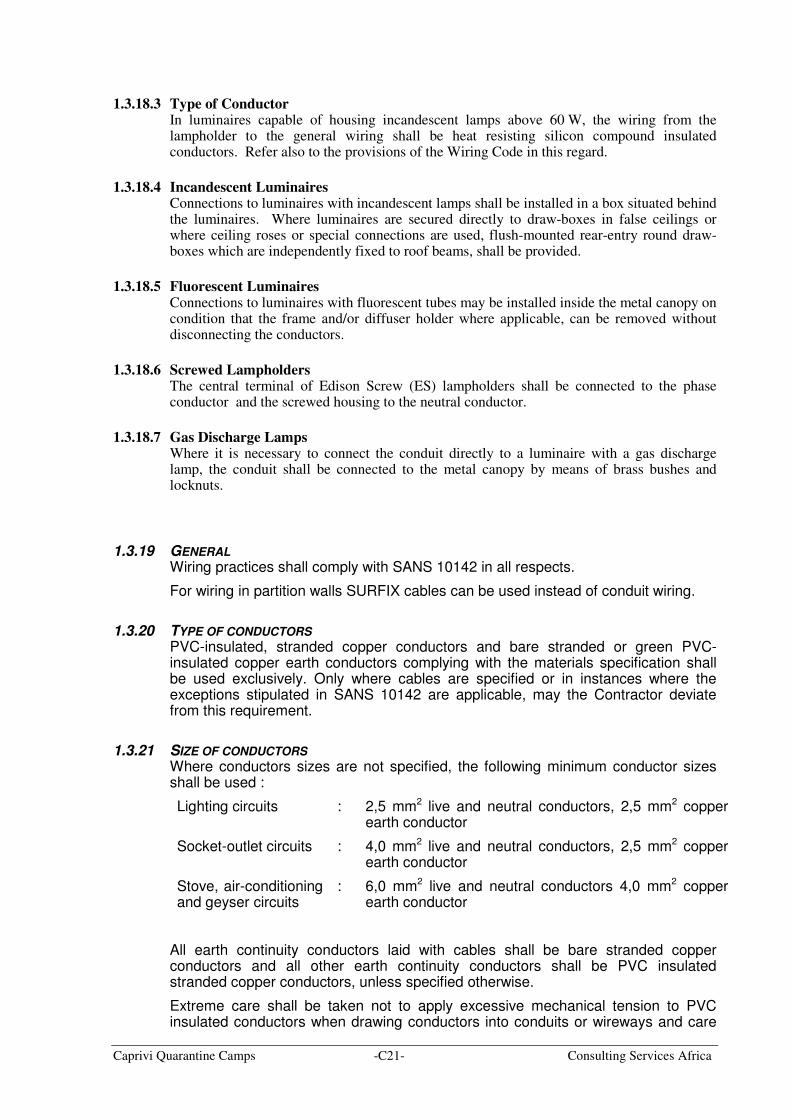
1.3.21 SIZE OF CONDUCTORS
Where conductors sizes are not specified, the following minimum conductor sizes shall be used :
Lighting circuits : 2,5 mm2 live and neutral conductors, 2,5 mm2 copper earth conductor
Socket-outlet circuits : 4,0 mm2 live and neutral conductors, 2,5 mm2 copper earth conductor
Stove, air-conditioning and geyser circuits
: 6,0 mm2 live and neutral conductors 4,0 mm2 copper earth conductor
All earth continuity conductors laid with cables shall be bare stranded copper conductors and all other earth continuity conductors shall be PVC insulated stranded copper conductors, unless specified otherwise.
Extreme care shall be taken not to apply excessive mechanical tension to PVC insulated conductors when drawing conductors into conduits or wireways and care
Caprivi Quarantine Camps -C22- Consulting Services Africa
shall also be taken not to draw PVC insulated conductors around sharp corners or protruding surfaces in conduits.
PVC insulated conductors shall be lubricated with high quality French chalk before they are drawn into conduit. The use of lubricating oil for drawing in PVC insulated conductors is not permitted. Conductors between an isolator and appliance shall be of the same cross-sectional area as the conductors fed to the isolator and shall, where necessary, be in flexible metal conduit. Wiring between isolators and fixed heating appliance terminals shall be in silicone rubber insulated conductors.
Wiring installed in wiring channels or power skirting shall be installed in the correct compartment to prevent any cross-overs and shall be bound together in groups not exceeding ten conductors by means of approved straps at spacings not exceeding 1m. No joints will be permitted in wiring.
Circuit wiring shall be of the loop-in system, and not more than four conductor ends will be allowed at any one termination point. Cutting away of wire strands of any cable will not be allowed and no jointing of conductors in draw boxes or the cutting away of insulation is permissible. Where joints are used, they shall be in heavy brass terminals with porcelain insulators.
Circuits for different services, e.g. lighting circuits, power circuits, intercommunication circuits and telephone circuits, shall each be routed in separate conduit runs.
A neutral conductor, equal in size to the phase conductors, shall be run to each three-phase outlet unless otherwise specified.
Joints will not be permitted in individual conductors forming part of any circuit.
1.3.22 WIREWAYS
All unarmoured conductors shall be installed in conduits, cable channels (trunking) or power skirting and shall under no circumstances be exposed. Cable channels and power skirting shall be of metal construction unless specifically approved to the contrary.
Contractors must note that common wireways will only be permitted for relatively light current-carrying conductors such as lighting and socket-outlet circuits. Heavy current-carrying conductors such as feeders to distribution boards and large power points, must be installed in separate conduits or wireways.
1.3.23 GROUPING OF CONDUCTORS
In cases where the conductors of more than one circuit are installed in the same wireway, the conductors of each separate circuit (including earth conductor) shall be taped at intervals of 1m with PVC tape.
Conductors entering switchboards or control boards shall be grouped and bound by means of plastic cable ties and not with PVC insulation tape.
1.4 CABLE TRAYS AND TRUNKING
1.4.1 GENERAL
Where more than 2 cables run together they shall be supported on a rack tray or covered in a trunk.
The Contractor shall supply and install all cable trays and/or ladders as specified or as required by the cable routes including the necessary supports, clamps, hangers, fixing materials, bends, angles, junctions, reducers, T-pieces, etc.
Caprivi Quarantine Camps -C23- Consulting Services Africa
Cable ladders and trays are schematically indicated on drawings and additional lengths may be added by the Contractor for ease of installation.
The Contractor shall arrange with the Main Contractor for the provision of holes and access through the structure and finishes.
Trays and trunking shall be an approved ladder type racking. They shall be prepared with good quality zinc aluminium paint.
Pre-manufactured bends must be used and all accessories shall be to the manufacturers’ recommendations.
Trays and trunks shall be continuous and supported throughout their entire length at suitable intervals to prevent sagging.
All components shall be as approved by the manufacturer.
In-trunking supports shall be provided in order to prevent the wires falling out when cover plates are removed.
All cables shall be secured to the racking or trays and flat bar supports by means of suitable approved strapping at intervals not exceeding 800mm on vertical runs and 1 200mm on horizontal runs. A maximum of 4 cables shall be strapped together.
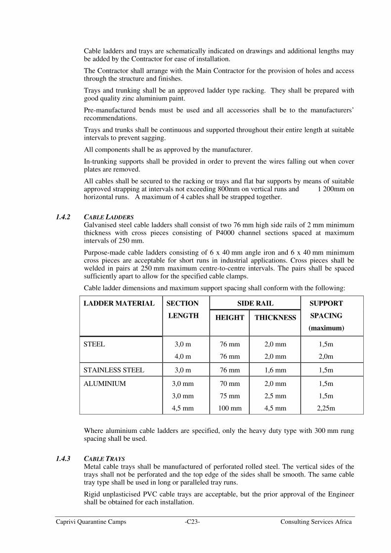
1.4.2 CABLE LADDERS
Galvanised steel cable ladders shall consist of two 76 mm high side rails of 2 mm minimum thickness with cross pieces consisting of P4000 channel sections spaced at maximum intervals of 250 mm.
Purpose-made cable ladders consisting of 6 x 40 mm angle iron and 6 x 40 mm minimum cross pieces are acceptable for short runs in industrial applications. Cross pieces shall be welded in pairs at 250 mm maximum centre-to-centre intervals. The pairs shall be spaced sufficiently apart to allow for the specified cable clamps.
Cable ladder dimensions and maximum support spacing shall conform with the following:
SIDE RAIL LADDER MATERIAL SECTION
LENGTH HEIGHT THICKNESS
SUPPORT
SPACING
(maximum)
STEEL 3,0 m
4,0 m
76 mm
76 mm
2,0 mm
2,0 mm
1,5m
2,0m
STAINLESS STEEL 3,0 m 76 mm 1,6 mm 1,5m
ALUMINIUM 3,0 mm
3,0 mm
4,5 mm
70 mm
75 mm
100 mm
2,0 mm
2,5 mm
4,5 mm
1,5m
1,5m
2,25m
Where aluminium cable ladders are specified, only the heavy duty type with 300 mm rung spacing shall be used.
1.4.3 CABLE TRAYS
Metal cable trays shall be manufactured of perforated rolled steel. The vertical sides of the trays shall not be perforated and the top edge of the sides shall be smooth. The same cable tray type shall be used in long or paralleled tray runs.
Rigid unplasticised PVC cable trays are acceptable, but the prior approval of the Engineer shall be obtained for each installation.
Caprivi Quarantine Camps -C24- Consulting Services Africa
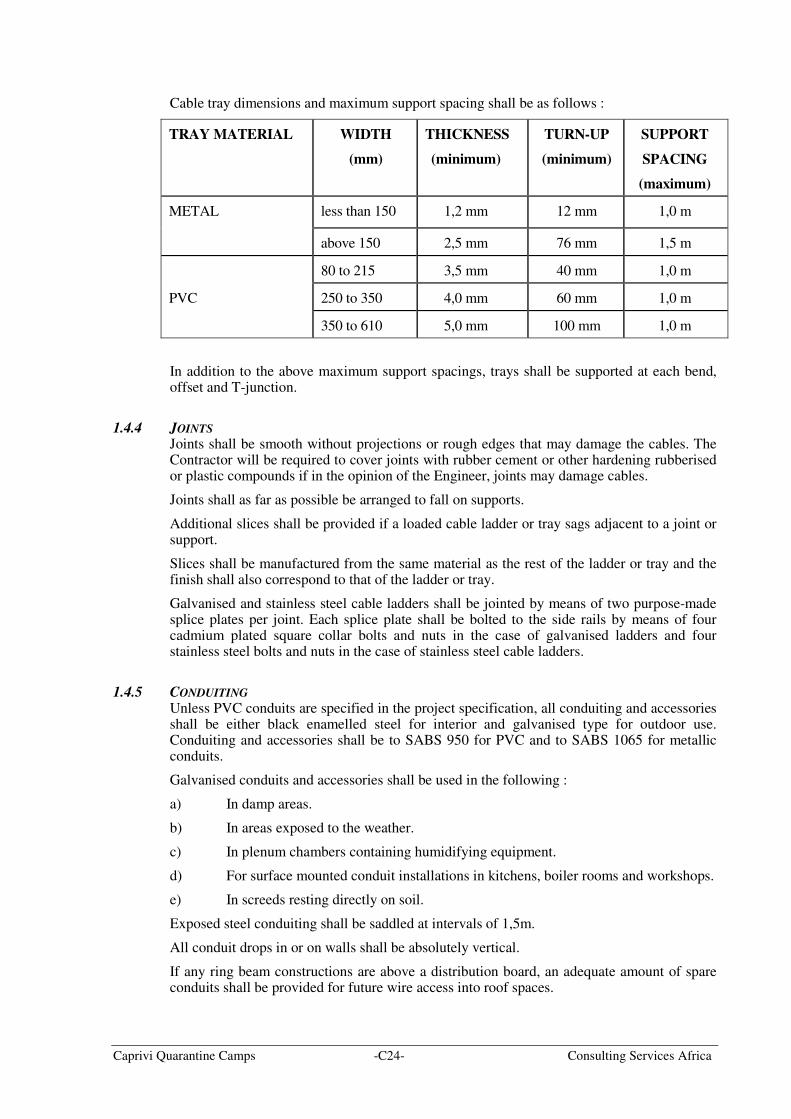
Cable tray dimensions and maximum support spacing shall be as follows :
TRAY MATERIAL WIDTH
(mm)
THICKNESS
(minimum)
TURN-UP
(minimum)
SUPPORT
SPACING
(maximum)
METAL less than 150 1,2 mm 12 mm 1,0 m
above 150 2,5 mm 76 mm 1,5 m
80 to 215 3,5 mm 40 mm 1,0 m
PVC 250 to 350 4,0 mm 60 mm 1,0 m
350 to 610 5,0 mm 100 mm 1,0 m
In addition to the above maximum support spacings, trays shall be supported at each bend, offset and T-junction.
1.4.4 JOINTS
Joints shall be smooth without projections or rough edges that may damage the cables. The Contractor will be required to cover joints with rubber cement or other hardening rubberised or plastic compounds if in the opinion of the Engineer, joints may damage cables.
Joints shall as far as possible be arranged to fall on supports.
Additional slices shall be provided if a loaded cable ladder or tray sags adjacent to a joint or support.
Slices shall be manufactured from the same material as the rest of the ladder or tray and the finish shall also correspond to that of the ladder or tray.
Galvanised and stainless steel cable ladders shall be jointed by means of two purpose-made splice plates per joint. Each splice plate shall be bolted to the side rails by means of four cadmium plated square collar bolts and nuts in the case of galvanised ladders and four stainless steel bolts and nuts in the case of stainless steel cable ladders.
1.4.5 CONDUITING
Unless PVC conduits are specified in the project specification, all conduiting and accessories shall be either black enamelled steel for interior and galvanised type for outdoor use. Conduiting and accessories shall be to SABS 950 for PVC and to SABS 1065 for metallic conduits.
Galvanised conduits and accessories shall be used in the following :
a) In damp areas.
b) In areas exposed to the weather.
c) In plenum chambers containing humidifying equipment.
d) For surface mounted conduit installations in kitchens, boiler rooms and workshops.
e) In screeds resting directly on soil.
Exposed steel conduiting shall be saddled at intervals of 1,5m.
All conduit drops in or on walls shall be absolutely vertical.
If any ring beam constructions are above a distribution board, an adequate amount of spare conduits shall be provided for future wire access into roof spaces.
Caprivi Quarantine Camps -C25- Consulting Services Africa
1.4.6 SPECIFICATION FOR THE REPAINTING OF POWER SKIRTING
Power skirting shall be treated and painted as follows:
a) Remove all covers from the skirting.
b) Remove and disconnect all socket outlets from the skirting.
c) Secure cable ends and insulate by means of insulation tape.
d) Screen all cabling in ducting by means of paper.
e) Descale and clean surface to be painted.
f) Screen surrounding wall and floor.
g) Spray paint power skirting with the correct paint.
h) Disassemble sockets from lids.
i) Spray paint all lids of power skirting with the correct paint.
j) Remove all screens and reassemble.
1.5 CONDUITS AND ACCESSORIES
1.5.1 SCOPE
This section covers the installation of conduits and conduit accessories in buildings and other structures for system voltages up to 600V.
1.5.2 CONDUIT SYSTEMS
Plain-end metallic conduit (black enamelled or galvanised mild steel) such as ‘BOSAL”, 'CHENEY', 'EASILOCK' and 'LOCFIT or similar conduit systems shall be used for exposed conduit. PVC conduit shall be used only under plaster.
Plain-end conduit and associated accessories shall be manufactured of mild steel having a minimum thickness of 0,9mm and shall comply with SABS 1007. Conduit manufactured of lighter gauge material will not be permitted.
Manual cold bends of conduit of nominal size up to and including 25mm is permitted, provided that the radius of the bend exceeds six times the nominal size of the conduit, with the external angle of the bend not exceeding 90°. In all other cases bends shall consist of suitable accessories. Bends shall comply with SANS 10142.
1.5.3 CONDUIT INSTALLATION
1.5.3.1 Positioning Conduits shall be installed as follows :
v) Exposed surface mount conduit Exposed surface-mount conduit shall be galvanised mild steel only.
vi) Open and closed roof spaces
Only galvanised mild steel conduit shall be used in exposed ceiling spaces. Black enamelled conduit shall be used in enclosed ceiling spaces.
vii) Walls, slabs etc
Galvanised mild steel conduit shall be used in surface mounted applications.
viii) Chased into walls
PVC conduit may be used where it can be chased into walls.
iv) Conduits cast into concrete shall be securely fixed in position before pouring commences.
Caprivi Quarantine Camps -C26- Consulting Services Africa
1.5.3.2 Installation requirements i) Position of outlets
All accessories such as boxes for socket-outlets, switches, lights, etc. shall be accurately positioned and shall be installed level and square, at the correct height from the floor, ceiling or roof level and in the correct position relative to building lines and equipment positions. All draw boxes shall be inaccessible after completion of the installation.
ii) Cover plates
Cover plates, either as part of the switch or socket assembly or with blank cover plates if unused shall be provided for all draw- and wall boxes. Blank cover plates shall match other cover plates in the same area.
iii) Draw-wires
Galvanised steel draw-wires shall be provided in all unwired conduits for future extensions, telephone installations and other services.
ix) Draw boxes
Draw boxes shall be installed at intervals not exceeding 15m in straight runs.
v) Bends
Bending and setting of plain-end conduit must be done with special benders and apparatus manufactured for this purpose and which are obtainable from the suppliers of the system. Damaged conduit resulting from the use of incorrect bending apparatus shall be completely removed and any wiring already drawn into such damaged conduits shall be completely renewed at the Contractor's expense.
A maximum of two 90° bends or the equivalent displacement will be allowed between outlets and / or boxes. All bends shall be made without heating the conduit or without reducing the diameter of the conduit. Inside radii of bends shall not be less than five times the outside diameter of the conduit (refer to SANS 10142).
vi) Wall socket-outlets
Where more than one outlet point is to be connected to the same circuit, the conduit shall continue directly to the next position from the previous outlet box on the same circuit. Where metal trunking is used, the conduit may be installed from the trunking directly to the outlet box provided that the conductors are looped between the outlets without any joints in the wires.
vii) Lighting points
Round drawboxes shall be [rovided for all lighting points. Where luminaires are to be fixed directly to the pendant box, the pendant box shall be fixed independently of the conduit installation.
viii) Access holes
All access holes in draw-boxes or other conduit accessories shall be securely blanked off by means of brass plugs to render the installation vermin proof.
1.5.3.3 Terminations i) Conduit ends
Conduit ends shall be cut at right angles to ensure that ends butt squarely at joints. Threads shall not be visible at joints and connections except at running joints. The total length of the thread on the two conduit ends shall not exceed the length of the coupling.
ii) Joints

Caprivi Quarantine Camps -C27- Consulting Services Africa
Joints shall be kept to a minimum. All conduit ends shall be reamed and all joints tightly screwed. Only approved couplings shall be used.
iii) Connections
Conduits shall be connected directly to draw-boxes with spouted connections. Conduits shall be screwed tightly home and no threads shall be visible.
iv) Continuity
Mechanical and electrical continuity shall be maintained throughout the conduit installation.
v) Switchboards, power skirting, etc.
Conduits shall be terminated by means of a brass female bush and two locknuts in pressed steel switchboards and distribution boxes, cable ducts, power skirting, etc. The conduit end shall only protrude far enough through the entry hole to accommodate the bush and locknut.
vi) Draw boxes and outlet points
A female bush and two locknuts shall be used to terminate conduits at draw boxes and outlet boxes without spouts. Where space permits, a coupling, brass male bush and locknut may be used with sufficient allowance for the reduction of the internal diameter by the male bush.
vii) Bush-nuts
Bush-nuts for the connection of earth conductors to conduits are not acceptable.
vii) Screws, bolts and nuts
Steel locknuts of thick gauge steel with milled sides shall be used in all cases. Cadmium-plated bolts and nuts shall be used except in cases where the installation is exposed to the weather, where brass bolts and nuts shall be used.
Screws shall be installed in all tapped holes in fittings and accessories and shall be completely screwed in to prevent damage to the screw thread by concrete or plaster.
1.5.3.4 Debris Care shall be taken to prevent debris or moisture from entering conduits during and after installation. Conduit ends shall be sealed by means of a solid plug which shall be screwed to the conduit end. Conduits shall be cleaned and swabbed to remove oil, moisture or other debris that may be present before conductors are installed. Swabs shall not be attached to the conductors.
1.5.3.5 Defects Each length of conduit shall be inspected for defects prior to installation, and all burrs shall be removed. Split, dented or otherwise damaged conduits, or conduits with sharp internal edges shall not be used and shall be removed from site. Conduits shall not be blocked by foreign media during or after installation.
1.5.3.6 Withdrawal of conductors To ensure that all electrical conductors are easily withdrawable from conduits and to ensure that there are no joints in the conductors, the Engineer's representative will have the right to have the conductors of any circuit removed for inspection at his discretion. If the conductors are found to be in a satisfactory condition after having been withdrawn, the Employer shall bear the cost of withdrawing and re-installing such conductors. Conductors found to have been damaged during installation or removal, or found with joints, shall be replaced and the cost shall be borne by the Contractor.
1.5.3.7 Surface installations i) Material
Caprivi Quarantine Camps -C28- Consulting Services Africa
All surface-mounted conduit shall be either galvanised or black mild steel. No PVC conduit installed on the surface of any structure will be accepted.
ii) Appearance All conduits shall be installed horizontally or vertically as determined by the route
and the Contractor shall take all measures to ensure a neat installation.
Where conduits are to be installed directly alongside door frames, beams, etc. that are not true, conduits shall be installed parallel to the frames, beams, etc.
All labels shall be removed from surface mounted conduit.
iii) Saddles Conduits shall be firmly secured by means of saddles and screws and in accordance
with SANS 10142. Where saddles are used to secure vertical lengths of conduit connected to surface mounted switch boxes or socket-outlet boxes, the saddles shall be spaced so that the intervals between the box and the first saddle, between any two successive saddles and between the last saddle and the ceiling or roof are equidistant. Conduits shall be secured within 150 mm before and after each 90° bend and within 100mm of each outlet box.
iv) Joints Joints will only be allowed in surface conduit lengths exceeding 3,5m. Threads
shall not be visible at joints of completed installations, except where running joints are used. Running joints will be allowed only when absolutely necessary. All running joints shall be provided with locknuts.
v) Accessories Inspection bends or tee pieces shall be used. Non-inspection type bends may be
used in the case of 32mm or 50mm diameter conduits. All draw-boxes supporting luminaires or other equipment shall be fixed independently of the conduit installation.
vi) Offsets Where an offset is required at conduit terminations or cross-overs, the conduit shall
be saddled at the offset.
vii) Cross-over Conduit routes shall be carefully planned to avoid cross-overs. Where cross-overs
are unavoidable, one conduit only shall be offset to cross the other. Cross-overs shall be as short as possible and shall be uniform. Alternatively, cross-overs shall be installed in purpose-made boxes. This method shall be employed on face brick walls and in other circumstances where required by the Engineer.
viii) Parallel conduit Parallel conduit runs shall be equidistant and saddles shall be installed in line.
Alternatively, a special clamp may be used to secure all conduits in unison. In the case of conduits of different diameters, the latter method shall only be used if a purpose-made clamp designed to accommodate the various conduit sizes, is provided.
ix) Painting of conduit Visible runs of surface-mount conduit shall be galvanised except where otherwise
approved, in which case surface mounted visible black conduits shall be painted in the same colour as the wall.
x) Boxes Where surface mounted switches or socket-outlets are installed indoors ivory
coloured epoxy coated pressed steel or PVC surface boxes shall be used.
1.5.3.8 Conduit installations in roof spaces Conduits in roof spaces shall be black mid steel or galvanised mild steel. PVC conduits in roof spaces will not be accepted.
Caprivi Quarantine Camps -C29- Consulting Services Africa
The conduit shall be installed in the ceiling spaces of buildings that have ceilings. Where these ceiling spaces can only be accessed by removing the roof panels; the Contractor shall take this into account when calculating his rates.
In buildings that do not have ceilings the conduit shall be installed along the wall plates and roof trusses and beams to the various light points, and vertically down the walls to the light switches and socket outlets. Installation of conduits suspended between the rafters will not be permitted.
Conduit in roof spaces shall be installed parallel or at right angles to the roof members and shall be secured at intervals not exceeding 1.5 m by means of saddles screwed to the roof timbers.
Nails or crampets will not be allowed.
Under flat roofs in false ceilings, or where there is less than 900mm clearance, or in instances where the ceilings are insulated with glasswool or other insulating material impeding access, the conduit shall be installed in a manner, which allows for wiring from below the ceilings.
Conduit runs from switchboards shall terminate in fabricated sheet steel draw-boxes installed directly above or in close proximity to the boards.
Spare conduits covering the total number of spare ways on switchboards, shall be provided between the boards and the roof draw-box.
As an alternative to above, a trunking channel that can accommodate all circuits may be installed from the switchboard to the roof space, provided that where the circuits enter the various conduits in the roof space, the conduits shall be terminated on the trunking channel with bushes or grommets to prevent damage to the conductors.
1.5.3.9 Fixing to walls Only approved plugging materials such a fibre plugs or plastic plugs, etc., and roundhead screws shall be used when fixing saddles, switches, plugs etc. to walls. Wooden plugs are not acceptable nor should plugs be installed in joints in brick walls.
1.5.3.10 Future extensions i) Open roof spaces
Conduits intended for future switches and socket-outlets, shall terminate 40mm above the tie beams in roof spaces with more than 900mm free space. The conduit ends shall be threaded and fitted with a coupling and brass plug.
ii) Cover plates
Unused boxes for switches and socket-outlets shall be covered with metal cover plates. Unused boxes for luminaires shall be covered with round galvanised metal cover plates which fit tightly against the finished surface.
1.5.3.11 Expansion joints Where conduits cross expansion joints in the structure, approved draw-boxes providing flexible connections in the conduit installation shall be installed.
The draw-box shall be installed adjacent to the expansion joint of the structure and a conduit sleeve, one size larger than that specified for the circuit, shall be provided on the side of the draw-box nearest the joint. The one end of the sleeve shall terminate at the edge of the joint and the other shall be secured to the draw-box by means of lockouts.
The circuit conduit passing through the sleeve shall be terminated 40mm inside the draw-box and in the case of metallic conduit, the conduit end shall be fitted with a brass bush. The gap between the sleeve and the conduit at the joint shall be sealed with 'Pratley Tic-Tac', silicone or equal sealing compound, to prevent the ingress of dirt. In the case of metallic conduit, an earth clip shall be fitted to the conduit projection inside the draw-box and the conduit bonded to the box by means of 2.5mm
2 bare copper earth wire and a brass bolt and nut.
Caprivi Quarantine Camps -C30- Consulting Services Africa
The end of the other circuit conduit shall be secured to the draw-box by means of locknuts and a brass bush in the case of screwed metallic conduit or a standard bushed adaptor for other conduit types.
In the case of metallic conduit, a 2,5mm2 bare copper wire shall be installed between the first
conduit boxes on either side of the joint, in addition to an earth wire which may be specified for the circuit. The conduit boxes shall be drilled and tapped and the earth wire shall be bonded to the boxes by means of lugs and brass screws.
Suitable steel cover plates shall be screwed to draw-boxes installed along the expansion joint.
Where a number of conduits are installed in parallel they shall cross the expansion joint of the structure via a single draw-box. A number of draw-boxes adjacent to each other will not be allowed.
1.5.4 OTHER SERVICES
Conduits may not be installed closer than 150mm to pipes of other services such as gas, steam, hot water or other materials which may damage the conduits or conductors. To prevent electrolytic corrosion, conduits shall not touch other pipe installations.
Conductors may not be drawn into conduits before the conduiting has been inspected and approved by the Engineer.
All conduit for communications services shall have draw wires as specified drawn in and left inside the conduits for future use.
All conduits shall be bushed and secured by lock-nuts to distribution boards, wall boxes, etc.
Spare conduits (10% with a minimum of two 20 mm and one 25 mm conduits) shall be run from the distribution boards into the roof space to cater for future circuits.