Embed Size (px)
Citation preview

14 DECEMBER | 2014
The wind industry in North America is booming. Yes, it always seems like it’s on a
roller coaster, but 2015 looks to be the best year ever. The USA already has over 62GW on-line, but a further 14GW are under construction with completion expected by the end of 2105. An additional 5 GW are in the final stages of development. AWEA’s best estimate is 80 GW by Jan 2016.
Any way you look at it, that’s a lot of energy — requiring a lot of con-struction in a fairly short period of time. The race is now on to complete projects and get them commissioned and making power as soon as feasi-ble.
That’s all fine and good, but it is also critical that the sites are ener-gized safely and with the best chance for reliable performance for the years to come.
At the end of the construction phase, all of the good work of the various contractors comes to a conclusion and it’s time to assure it was all done according to specifica-tion. That’s where site acceptance testing comes in. But which electrical components should be tested? What testing criteria should be used? Most importantly, who should perform the testing? Let’s see…
WHAT SHOULD BE TESTED?The high-voltage components of a wind project normally include everything outside of the turbine itself. In some designs, the step-up transformer is located inside the turbine, so that should be considered as well; but as those designs are always dry-type units, the testing has a different scope.
For our purposes, let’s look at a traditional design where the step-up is an external oil-insu-lated pad-mount transformer at each turbine, feeding a collection system at high voltage through a series of collection points, and finally brought together at a utili-ty-grade substation for transmis-sion onto the grid.
Here, the critical elements are the multiple transformers, the collection cables and the related splices, terminations, as well as the ground scheme. Of course, the substation is a project in itself, and includes all of the typical util-ity equipment: GSU transformer, protective relays, switchgear, and grid reliability communications devices.
All of that is pretty obvious; what is really being tested falls into three distinct areas:
• Did the engineering firm de-sign the system properly so it will be safe and reliable?
• Did the OEM of the equipment supply what was intended? Is it in proper working condi-tion?
• Did the electrical contractor correctly assemble and install all of the components?
Electrical Acceptance Testing for Wind Energy Sites
inFOCUS: CONSTRUCTION
By Paul IdziakShermco Industries
Good design and good construction means reduced maintenance costs

windsystemsmag.com 15
It is also critical that all one-line drawings be confirmed and/or updated to accurately reflect what was actually built. This is critical for future maintenance inspections and testing. One often-overlooked — but important — element of the acceptance process is the confir-mation of any coordination studies, arc flash hazard analysis, and other safety-related component testing.
WHY TEST?According to both the NFPA 70B Recommended Practice for Elec-trical Equipment Maintenance and the CSA Z463 Guideline on Maintenance of Electrical Systems, it is critical to safety compliance that the equipment work properly when energized. This can only be confirmed by initial testing as well as periodic
ALSO IN THIS SECTION:
18 Record low costs drive opportu-nities for the U.S. wind energy industry
19 Interior issues transmission right-of-way to Deepwater Wind
20 BASF receives type certification for offshore grout

16 DECEMBER | 2014
testing. Establishing a solid baseline for trending analysis is also useful for Preventative (PM) and Predictive Maintenance (PdM) planning. So, reliable performance, reduced main-tenance costs, and a safer work envi-ronment are all drivers for competent and thorough acceptance testing.
WHAT CRITERIA SHOULD BE FOLLOWED?Of course, the manufacturer’s specifi-cations and recommendations should always be followed, but the overall system performance is evaluated based on visual and mechanical inspections, electrical testing, and comparison with expected testing values. To that end, industry consen-sus standards have been developed to assure proper consideration is given to this testing.
Since 1972, the International Elec-trical Testing Association (NETA) has published Standards for Acceptance Testing for Electrical Power Equip-ment and Systems (ATS), and, since 1975, the companion MTS Mainte-nance Testing Standards. In 2013, the ATS was approved as an American National Standard (ANSI). These documents provide both the test methodologies and expected results for testing most types of electrical equipment and serve as the basis for a good acceptance test plan.
Additionally, NERC/FERC guide-lines provide critical information for substation settings and reliability ex-pectations. Experienced engineering support and well-trained technicians should be very familiar with these standard procedures, and should be able to apply them to the unique requirements of a wind generation facility.
HOW DO I SELECT A QUALIFIED THIRD-PARTY TESTING COMPANY?The value of testing by a true third party is that the scope of work and
the expected results are defined and managed by the hiring owner of the wind site. This assures a true, unbiased review of the engineering and construction before commis-sioning and take over. Many prob-lems can be identified and rectified while the site is still offline, reduc-ing incidental losses and allowing the responsible contractor address the issue safely and efficiently.
The technicians who perform the testing should be well-trained and experienced. Again, ANSI/NETA Standard for the Certifica-tion of Electrical Testing Techni-cians (ETT) is well established as a benchmark for qualifications.
Each testing crew should be led by a Level III or higher certified technician, and all crew members should be capable of completing the testing with a complete knowledge of the hazards involved as well as the ability to make decisions regarding the serviceability of the equipment and system.
A company that is designated as a NETA Accredited Company will meet all of these criteria. It is the site owner’s responsibility to provide all of the engineering documentation such as short circuit analysis, coordination studies and protective device settings as well as drawings and equipment manuals.
Qualified testing companies can review the scope and jointly develop a plan for testing. They should notify the owner before any testing and report the results of any deficiencies as soon as practical so corrections can be made. A detailed final report including baseline results should also be provided in a timely manner.
SO WHAT ELSE?Good electrical system design should always include consider-ation of the maintenance that must be performed over the life of the
system. Acceptance testing can be useful in confirming the effec-tiveness of this aspect, as well as establishing the baselines required for performance trending.
Wind generation sites do have a specific set of performance issues that should be addressed. Often, due to cost restrictions possibly based on short the financial goals, there is little consideration given to the future cost of maintenance.
Good examples include the current issues many sites face with oil-insulated transformers that were built and installed according to specification but are not proving reliable in the field. Knowing this is an issue, the testing company should provide trending oil analysis during the acceptance process.
There have also been many issues with faulty high-voltage cable terminations and splices within the collection system. These cables should be tested carefully using sensitive equipment to assure that no imminent faults exist, not just the typical high potential testing.
What about the turbines? Since turbine commissioning typically falls to the OEM, they hold the risk for any premature failures. Certainly, however, a full set of test results and warranty actions should be made available for each turbine before the responsibility is assumed by the owner at the end of warranty. All of these test results, especially those that can trended, should be utilized in conjunction with a condition based monitor-ing plan to form the basis for good maintenance planning.
Acceptance testing, therefore, should be more than just a final step of the construction phase of a proj-ect. It should be utilized to assure that the owner is getting what he is expecting: a well-designed, prop-erly constructed, and safe power generation facility.
InFOCUS: Construction

windsystemsmag.com 17
BUILDINGSTRONG
wanzek.com
Following the Government of Québec issuance of the decree authorizing the construction and operation of Mont-Rothery, EDF EN Canada Inc., a subsidiary of EDF Energies Nouvelles, today announced that the construc-tion phase of the 74 MW Mont-Roth-ery wind project has commenced.
Mont-Rothery Wind Project, consisting of 37 turbines supplied by Senvion, is expected to be placed into service at the end of 2015.
The wind farm will be located on public lands in the MRC of Haute-Gaspésie and MRC of Côte-de-Gaspé. Under the project, these MRCs will share a combined royalty payment of CAD $185,000 annually. Construction Energie Renouvelable has been select-ed as the contractor to implement the project.
“EDF EN Canada welcomes the decree authorizing the construction and operation of the Mont-Rothery Wind Project and offers a sincere thanks to the Government of Québec for its permission to proceed with this project,” said Al Kurzenhauser, Chief Operating Officer for EDF EN Canada. “With an investment of close to CAD $175 million, the project will create about 150 jobs during the construc-tion phase, and seven permanent operation and maintenance jobs. We are proud to start this project and especially grateful to all of the stake-holders who contributed to achieving this milestone.”
“The wind industry has become in the last decade a key element for the energy industry in Quebec,” said the Minister of Energy and Natural Resources and Minister responsible for the Northern Plan, Pierre Arcand. “This development has allowed the emergence of a whole new sector of our economy. Mont-Rothery is a prime example of how wind projects benefit the regions and aboriginal communi-ties where they are located.”
Mont-Rothery represents the final project of the seven awarded to EDF EN Canada in 2008 and 2010 through Hydro-Québec Distribution’s call for
tenders to commence construction. The company portfolio of projects represents 1 GW in Quebec.
— Source: EDF EN Canada
Construction underway at EDF EN project in quebec

18 DECEMBER | 2014
InFOCUS: Construction
With fall comes the harvest of mega-watts promised.
As would be expected by third quarter’s end, wind energy project developers are cruising into the later stages of construction on many — but hardly all — of their record number of projects. The completed megawatts are beginning to add up.
In fact, the U.S. wind industry was at its busiest ever in the third quarter while completing more of the wind projects that were under construc-tion at the start of the quarter. The American Wind Energy Association (AWEA) reported that 419 MW went online during the third quarter, bring-ing the 2014 total to 1,254 MW.
But while the construction cycle continues to mature, the biggest story remains what’s still under construction — and the number of megawatts that can potentially begin construction. Some 13,600 MW across 105 projects were still being built as the fourth quarter began. The recent completion of the transmission lines developed under Texas’s Competitive Renewable Energy Zone model continues to be a huge enabler of construction. Of the 13,600 MW under construction, 7,600 MW are in Texas. Nationally, the factors helping to drive construction activity are wind energy’s record low costs and high demand from utilities for the clean, affordable energy source.
As of September 30, 46,400 wind turbines with a total generating capaci-ty of 62,300 MW were operating in the U.S., according to AWEA’s count.
Also of note, AWEA’s third quarter numbers showed that another 3,700 MW of projects under pre-construc-tion development have inked off-take agreements with power purchasers. Having a power contract in place, of course, is a good indication that a proj-ect will get built.
Those who have been in the wind industry for some time know that when it comes to project comple-tion news, a given year typically starts quietly before ramping up by the third quarter and then going full steam as the year closes out. Typically, 60-70 percent of annual installations are completed in the fourth quarter. One reason for this is that during many years, developers are often pushing hard until Dec. 31 to finish projects before deadlines to qualify for the Production Tax Credit (PTC). This year’s historic under-construction figure foreshad-ows not just a busy holiday season, but a strong 2015 as well, when the majority of the projects started un-der the last extension of the PTC are expected to finish construction.
The most recent PTC exten-sion removed the typical year-end frenzy from the equation because it required that project construction need only start, rather than be com-pleted and online, by the end of last year for them to qualify. This PTC language tweak was badly needed in order to give the industry’s supply chain time to ramp back up in 2013 after grinding to a near halt in 2012 as a result of the threatened expira-tion coming at the end of that year. This time around, therefore, while the fourth quarter will be busy, don’t expect the 13,600 MW currently un-der construction to all be completed by New Year’s Eve.
Looking beyond 2015, a lot more construction could be on the way — that is, if there’s an appropriate pol-icy environment in place. The U.S. Department of Energy’s Wind Vision report, in peer review since it was previewed at AWEA’s WINDPOW-ER 2014 Conference & Exhibition, states that wind energy capacity
can double by 2020, and provide 10 percent of America’s electricity — and then double again by 2030, to 20 percent of the grid. It projects that by 2050, wind can provide as much as 35 percent of the nation’s elec-tricity. At that point, wind would be one of the leading sources of electric generation in the nation.
The Wind Vision becomes all the more compelling when considering that the U.S. industry is on pace so far to meet the 2030 goal, as outlined in an initial report produced by the George W. Bush administration in 2008.
In order to make that vision reality, it is crucial that the PTC is extended. AWEA CEO Tom Kier-nan has expressed optimism that Congress will extend the PTC and continue its success story, one that features a domestic wind industry supply chain of more than 500 facto-ries in 43 states. AWEA is calling on industry members to contact their Members of Congress and urge them to take action on an extension.
Record low costs drive opportunities for the U.S. wind energy industry
By Carl LevesqueThe American Wind Energy Association
Industry at Large

windsystemsmag.com 19
704.872.8888
860 Connor St • Statesville, NC 28677F: 704.872.5777 • www.rpmachine.com
for Gear Machinery
Gould & Eberhardt is a pioneer in high-speed gear gashing with large diameter carbide-inserted cutters. Our new line of machines has a rigid design and heads engineered with state of the art gear gashing cutter technology. Gear gashing technology has opened many gear cutting applications in wind energy, mining, off-highway construction and other coarse pitch gearing.
Our gasher/hobbers are equipped with the new G&E interchangeable cutter head design. This design provides the option for both internal and external heads on a single column machine with capacities up to 5.5 meters.
for Gear Machinery
Gould & Eberhardt is a pioneer ir ir n high-speed hhii wi withth la la ddiaia t rbrbiidd
for Gear Machinery
for Gear MachineryYour #1 Source
earing.
d
2.13_GE-Half_WindSystems.pdf 1 5/22/14 10:17 AM
Secretary of the Interior Sally Jewell and Bureau of Ocean Energy Management Acting Director Walter Cruickshank recently announced that BOEM has offered a right-of-way (ROW) grant to Deepwater Wind Block Island Transmis-sion System, LLC (Deepwater Wind) for the Block Island Transmission System (BITS).
“This is a major milestone for offshore renewable energy in the United States,” said Secretary Jewell. “This decision marks the first right-of-way grant offered in fed-eral waters for renewable energy transmission, paving the way for Block Island, the only Rhode Island community not connected to the grid, to have access to clean, afford-able renewable energy. Today’s announcement is an excit-ing development for Block Island, but it also represents a big step in our nation’s sustainable energy future.”
Deepwater Wind’s proposed project would entail the installation of a bi-directional submerged transmission cable between Block Island and the Rhode Island main-land. The transmission system would serve two purposes:
1) connect Deepwater Wind’s proposed 30 MW Block Island Wind Farm, located in Rhode Island state waters about 2.5 nautical miles southeast of Block Island, to the Rhode Island mainland; and 2) transmit power from the existing onshore transmission grid on the mainland to Block Island. The ROW corridor, which is about eight nautical miles long and 200 feet wide, comprises the por-tion of the transmission line that crosses federal waters.
“Today’s announcement builds on Interior’s work to stand up a sustainable offshore wind program for the Atlantic Coast,” said Cruickshank. “We look forward to working with Deepwater Wind to bring this this offshore infrastructure project to fruition.”
Once both the agency and Deepwater Wind have agreed upon the terms and conditions of the grant, BOEM will send the grant to Deepwater Wind for execution, and the company will be required to pay the first year’s rent and provide financial assurance. Once executed, BOEM will finalize its review of Deepwater Wind’s General
Block Island receives first renewable energy transmission permit for federal waters
Department of the Interior issues transmission right-of-way for Deepwater Wind offshore project

20 DECEMBER | 2014
Activities Plan, which describes proposed installation activities and conceptual decommissioning plans for the transmission system. The General Activities Plan would be the first approved for an offshore wind energy project for a transmission system in Federal waters.
The majority of the activities and permanent structures related to the Block Island Wind Farm will be sited in state waters and lands, making the U.S. Army Corps of Engineers the lead federal agency for analyzing the potential environmental effects of the project under the National Environmental Policy Act (NEPA). As a portion of the proposed project would be located on the federally managed Outer Continental Shelf, the project must secure a ROW grant from BOEM before proceeding. BOEM
has participated as a cooperating agency in the NEPA analysis and associated consultations led by the Corps.
In September 2014, the Corps completed an Environ-mental Assessment (EA) for the Block Island Wind Farm and BITS, and issued a Finding of No Significant Impact. Before adopting the EA, BOEM conducted an independent review of the EA and determined that no reasonably foreseeable significant impacts are expect-ed to occur as the result of the preferred alternative, or any of the alternatives contemplated by the EA. On October 27, 2014, BOEM issued a Finding of No Significant Impact for the issuance of a ROW grant, and approval of the General Activities Plan, with mod-ifications.
MasterFlow 9500 from Master Builders Solutions by BASF is the first product of its kind to receive a DNV GL (Det Norske Veritas Germanischer Lloyd) certificate for Offshore Concrete Struc-
tures. The Type Approval Certificate issued by the internationally acknowledged test and certification body, which specializes in oil, gas and maritime services as well as in energy and sustainability,
High-strength, fast curing compound deemed suitable for offshore concrete structuresBASF receives type certification for offshore grout
Interior issues transmission right-of-way to Deepwater Wind
windsystemsmag.com 21
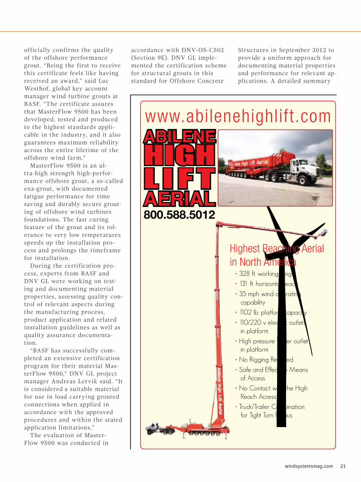
Highest Reaching Aerialin North America
• 328 ft. working height
• 131 ft. horizontal reach
• 35 mph wind operating capability
• 1102 lb. platform capacity
• 110/220 v electric outlets in platform
• High pressure water outlet in platform
• No Rigging Required
• Safe and Effective Means of Access
• No Contact with the High Reach Access
• Truck/Trailer Combination for Tight Turn Radius
800.588.5012
www.abilenehighlift.com
officially confirms the quality of the offshore performance grout. “Being the first to receive this certificate feels like having received an award,” said Luc Westhof, global key account manager wind turbine grouts at BASF. “The certificate assures that MasterFlow 9500 has been developed, tested and produced to the highest standards appli-cable in the industry, and it also guarantees maximum reliability across the entire lifetime of the offshore wind farm.”
MasterFlow 9500 is an ul-tra-high strength high-perfor-mance offshore grout, a so-called exa-grout, with documented fatigue performance for time saving and durably secure grout-ing of offshore wind turbines foundations. The fast curing feature of the grout and its tol-erance to very low temperatures speeds up the installation pro-cess and prolongs the timeframe for installation.
During the certification pro-cess, experts from BASF and DNV GL were working on test-ing and documenting material properties, assessing quality con-trol of relevant aspects during the manufacturing process, product application and related installation guidelines as well as quality assurance documenta-tion.
“BASF has successfully com-pleted an extensive certification program for their material Mas-terFlow 9500,” DNV GL project manager Andreas Lervik said. “It is considered a suitable material for use in load carrying grouted connections when applied in accordance with the approved procedures and within the stated application limitations.”
The evaluation of Master-Flow 9500 was conducted in
accordance with DNV-OS-C502 (Section 9E). DNV GL imple-mented the certification scheme for structural grouts in this standard for Offshore Concrete
Structures in September 2012 to provide a uniform approach for documenting material properties and performance for relevant ap-plications. A detailed summary

22 DECEMBER | 2014
of the material properties and conclusions from the certifi-
cation process of MasterFlow 9500 is stated on the DNV Type
Approval Certificate (No. K-5944, issued 2014-08-05).
Faster installation, protected investmentIn addition, MasterFlow 9500 also reduces the overall costs of offshore installations. The material develops a high strength very early on and can be applied at lower tempera-tures compared to conventional products. Considering the total cost of implementation, the time MasterFlow 9500 can save is a big factor in lowering the costs.
Also, provided the product is applied correctly, MasterFlow 9500 ensures a maintenance free connection between the tubular steel members for offshore wind turbine foundations.
“Achieving Type Approval Cer-tification for MasterFlow 9500 provides both FoundOcean as installation specialist and its cli-ents with increased reassurance of the performance of this ma-terial. This is extremely helpful and protects the investment in offshore wind energy”, says An-drew Venn, Marketing Director at FoundOcean, a globally active specialized supplier of offshore wind turbine installations.
MasterFlow 9500 was recently used on the West of Duddon Sands wind farm project in the UK, where 108 monopile foundations were installed in a record breaking period of just five months. In 2013, the performance grout was used, for instance, on the Gwynt-Y-Môr project with 160 monopiles in the Irish Sea as well as in the grouting of numerous test and demonstration turbines from several manufacturers, includ-ing the world’s currently most powerful offshore turbine with a rotor diameter of 164m and a capacity of 8 MW.
BASF receives type certification for offshore grout
24 DECEMBER | 2014
Maintenance Testing • Reliability based maintenance strategy • Helps maintain an electrically safe workplace • Benchmark performance for aligning priorities • Supports Predictive and Pro-active Maintenance Practices
16 Locations serving North America
Acceptance Testing • Collector system cables and accessories • Substation transformers • Relays and controls • Pad mount transformers • Baseline insulating oil analysis
Electrical Systems Testing
What should I test and how often?You got questions? Shermco Industries has the answers. By using industry standards and recommended practices, many of which we helped develop, we can get your facility on a healthy schedule that makes sense for reliability, safety and your budget. All testing based on ANSI/NETA ATS and MTS standards. Test what’s important. Test what fails. Test what is expensive and hard to get. Spend your time, energy and money where it counts.
888.SHERMCO SHERMCO.COM
ANSI/NETA ATS-2013
S T A N D A R D F O RACCEPTANCE TESTING SPECIFICATIONSF O R E L E C T R I C A L P O W E R EQUIPMENT AND SYSTEMS
ANSI/NETA MTS-2011
S T A N D A R D F O RMAINTENANCE TESTING SPECIFICATIONSF O R E L E C T R I C A L P O W E R EQUIPMENT AND SYSTEMS
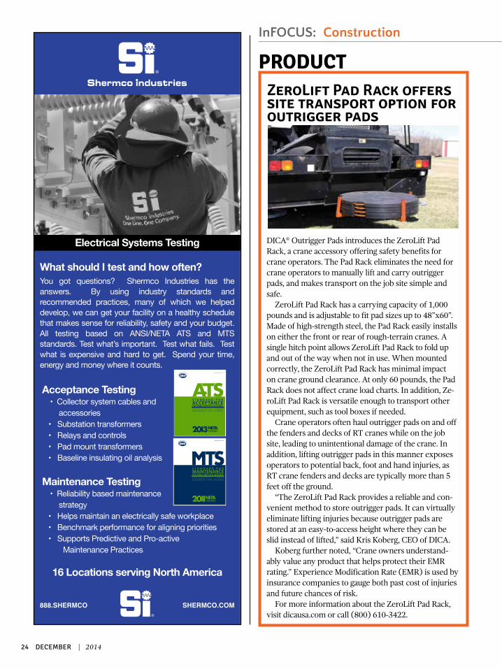
DICA® Outrigger Pads introduces the ZeroLift Pad Rack, a crane accessory offering safety benefits for crane operators. The Pad Rack eliminates the need for crane operators to manually lift and carry outrigger pads, and makes transport on the job site simple and safe.
ZeroLift Pad Rack has a carrying capacity of 1,000 pounds and is adjustable to fit pad sizes up to 48”x60”. Made of high-strength steel, the Pad Rack easily installs on either the front or rear of rough-terrain cranes. A single hitch point allows ZeroLift Pad Rack to fold up and out of the way when not in use. When mounted correctly, the ZeroLift Pad Rack has minimal impact on crane ground clearance. At only 60 pounds, the Pad Rack does not affect crane load charts. In addition, Ze-roLift Pad Rack is versatile enough to transport other equipment, such as tool boxes if needed.
Crane operators often haul outrigger pads on and off the fenders and decks of RT cranes while on the job site, leading to unintentional damage of the crane. In addition, lifting outrigger pads in this manner exposes operators to potential back, foot and hand injuries, as RT crane fenders and decks are typically more than 5 feet off the ground.
“The ZeroLift Pad Rack provides a reliable and con-venient method to store outrigger pads. It can virtually eliminate lifting injuries because outrigger pads are stored at an easy-to-access height where they can be slid instead of lifted,” said Kris Koberg, CEO of DICA.
Koberg further noted, “Crane owners understand-ably value any product that helps protect their EMR rating.” Experience Modification Rate (EMR) is used by insurance companies to gauge both past cost of injuries and future chances of risk.
For more information about the ZeroLift Pad Rack, visit dicausa.com or call (800) 610-3422.
PRODUCTZeroLift Pad Rack offers site transport option for outrigger pads
InFOCUS: Construction

windsystemsmag.com 25
OwnEnergy and Mortenson Con-struction recently announced the completion of construction on the Windthorst II Wind Farm located in Windthorst, Texas, approximate-ly 110 miles northwest of Dallas.
OwnEnergy developed the project and a fund managed by BlackRock, the world’s largest asset manager, purchased a majority interest in the project in December 2013.
The Windthorst II Wind Farm will provide $1 million in property tax payments to Archer County and create 3 to 4 full time operation and maintenance jobs for the lifetime of the project.
“Completing construction on the Windthorst II wind project, which is our sixth wind farm to spin and our seventh completed
project overall, is a major milestone for OwnEnergy” said OwnEnergy Founder and CEO Jacob Susman. “We are proud to demonstrate our construction and asset management capabilities with the completion of Windthorst II. What’s more, we are thrilled to work with Black-Rock and Mortensen to bring clean, cost-competitive wind energy to Texas. We appreciate the long-term support from the community lead-ers and residents of Archer County, and we are looking forward to con-tinuing our commitment to Texas’s clean energy economy.”
Mortenson was responsible for the engineering, procurement and construction of the project, includ-ing, the erection of 28 2.4-MW Sie-mens turbines; foundations; under-ground collection; 69kv substation
and access roads. Approximately 160 jobs were created throughout the course of construction.
The Windthorst II project is the 26th wind facility the renewable energy contractor has built in the state to date out of a total of 140 wind projects completed or under construction throughout North America.
“We are very pleased to have entered into a relationship with OwnEnergy as they continue to grow their wind portfolio and make their mark in the industry,” said Tim Maag, VP and general man-ager of Mortenson’s Wind Energy Group. “We applaud their growing commitment to building projects with local ownership.”
— Source: Mortenson
NTCWIND.COM
· Tensioning equipment is custom-ized for any bolt configuration or clearance
· Our customized equipment can be modified or repaired in the field, reducing downtime
· Certified pump gauges are recalibrat-ed with each foundation
· Professional reports routinely provid-ed for each foundation tensioned
· Free bolt cap installation with tensioning service
BOLT TENSIONING
RAISING THE BAR IN BOLT TENSIONING
IRONCLADINTRODUCING
Protects the bolt from contact with grout and
prevents grout from going down into the bolt sleeve.
Mortenson completes Windthorst II for OwnEnergy

26 DECEMBER | 2014
By Kate Nation
Wanzek Construction, Inc. has spent the past four decades building an organization that successfully erects infrastructure for strong sectors including power, renewable energy, oil & gas, heavy/civil, and industrial agriculture.
Backed by parent company, Mas-Tec, Inc., a leading North American infrastructure construction company, Wanzek is equipped with a compre-hensive understanding of the indus-tries it serves, innovative technology, and a wholly owned fleet of state-of-the-art specialty construction equip-ment. The company has geographic reach, scalability and overall financial strength. But Wanzek’s most valuable asset, according to the company’s leadership, is its people.
With interrelated, client-focused teams, including a national work-force of OQ-qualified professionals, Wanzek has established a work process that supports the company’s policy to provide services that exceed client expectations and requirements. Among the many roles that maintain Wanzek’s success, the project manag-er is key to managing and controlling the outcome of a project. Arnie Jelinek, Wanzek’s vice president, cites the company’s project managers as instrumental in navigating the unique characteristics and challenges that are inherent in most job sites.
“Planning, organization and com-munication before, during and after site work is essential to each project’s success,” Jelinek said. “Wanzek’s project management team is contin-uously elevating site management through sound procedures, controls, and effective communication. These dedicated individuals have a special
set of communication and leadership skills that help drive the whole team through the dynamic nature of a typical day.”
A typical day can vary based on industry focus. As exemplified by a wind energy project, a typical day for a project manager includes a wide range of tasks including reviewing project status, reviewing safety plans, meeting with owners, quality con-trol, finding and addressing issues, coordinating with engineers and supervisors, leading project teams, forecasting, maintaining material flow, managing timelines, and over-seeing budgets.
Wind projects are very fast paced. Once a contract has been signed and a plan has been finalized, there is no downtime until the project has been completed. A typical wind project takes six months. This challenging pace is what engages Nick Ibach, project manager at Wanzek.
“I really enjoy the quick pace of a wind project,” Ibach said. “It is very hands-on and requires a consistent level of attention. A project with a tight schedule gives me the oppor-tunity to engage a range of skills and provides a tremendous sense of satisfaction upon completion.”
Led by project managers like
Wanzek Construction, Inc.Profile
Strong emphasis on project management drives wind industry success story
INFOCUS

windsystemsmag.com 27
Ibach, Wanzek’s wind teams have installed more than 5400 MW of wind generation capacity across the country for some of the biggest names in the industry. Services include building, expanding, and maintaining facilities while working closely with owners to develop
detailed, conceptual budgets and construction sched-ules, address topography challenges and complete civil and electrical design. The successful completion of each project is due largely to communication between project managers and owners. During construction, Ibach spends one to two weeks a month on-site. He meets with owner representation multiple times a day by phone and on-site weekly.
“Communication is critical,” Ibach said. “It is the means by which everyone on the team, from owner to superintendents to our field force, stay informed regard-ing project status, any challenges that have been present-ed and the chosen method for handling them. I consider communication to be one of the ways with which I try to lead by example. If everyone is informed and has the right tools for the job, we will provide a higher level of service.”
Other essential qualities for a project manager include the ability to coordinate people and processes, organiza-tional and planning skills, as well as dedication and flexi-bility. Ibach cites coordination as fundamental to keep-ing a project moving forward. The long hours involved in a project require dedication and the implementation of prioritization methods to stay on course. Even with high levels of planning and coordination, problems can present themselves. Incremental weather or unexpected issues like concrete breaking can challenge a team to regroup quickly.
“We have learned to be dime-rate meteorologists,” Ibach joked “I begin a project as prepared as possible but knowing that my crew and I need to be adaptable. Part of being successful on a project is having the ability to face a challenge, regroup, and quickly implement a new plan that keeps the project on track and affects the schedule and budget as little as possible.”
Some challenges come with the territory. As wind farms are generally constructed over hundreds of square miles, it can be a difficult to coordinate a wind project geographically. Unlike many construction sites, a project manager or supervisor cannot physically walk the whole project. Getting from a turbine installation to the laydown yard can often be an hour-long drive. Ibach believes that successful coordination relies on having a really great team.
“We have built a talented team and developed a high level of trust,” Ibach says. “Our people are safety-orient-ed, skilled and dedicated people who are invested in the success of the projects they work on.”
Wanzek is continuously strengthening teams by hiring the top technicians and operators and offering continual training.
For more information about Wanzek, its teams, and its projects, visit www.wanzek.com.
28 DECEMBER | 2014
Conversation
Norm Tooman Construction recently rebranded itself as NTC Wind Energy. How did that come about?We were involved in general con-struction for a long time before getting into the wind business. It seemed appropriate to be more spe-cific about our current concentration and expertise. In honor of Norm Tooman, who started the business, we wanted to keep his name but got tired of spelling it to everyone, so NTC seemed like the best answer. Besides, I had to keep peace in the family and especially with my wife, who is the majority stock holder, president and the daughter of Norm Tooman.
The company is widely known for its Ironclad bolt caps. Could you tell our readers about the product?We were the first to introduce and patent bolt caps in the wind industry, back in the days that we were still building lattice towers. We saw that
the bolts were rusting out and sought a solution that did not require paint-ing the bolts every few years, while preventing water from going through the threads and into the bolt sleeves under the surface of the foundation. There have been a number of gener-ations of our IronClad bolt caps over the years in our ongoing attempt to improve performance and keep pric-es low. For example, we’ve recently added a small vent to the standard duty bolt cap to prevent expan-sion and contraction and allow any condensation to escape, while adding no additional cost to the customer. Actually, bolt caps are intended to protect the grease on the bolt from dissipating or collecting dirt. A thor-ough coating of high-grade and high dropping point, anticorrosion grease is essential in combination with the bolt cap for proper protection. We’re very impressed with the performance of Corrosion Block grease and often sell it or use it with our caps.
How does the Extreme Duty bolt cap differ from the original?Our IronClad Extreme Duty bolt caps were developed in cooperation with a BOP engineer. We were addressing potential damage caused to the caps in cold environments from sheet ice dropping off the blades and, at the same time, addressing applications near saltwater, where the cap might be partially or completely filled with grease or cosmoline for extra protection against the elements. We ended up designing a 14-ounce polypropylene monster of a cap that incorporates a grease injection port. We also designed it to so that the same cap fits rods from number 10
grade 75 to number 11 grade 150. It actually has four sealing surfaces against the tower flange including a flexible skirt on the outside, an o-ring and the two o-ring retainers, all of which bottom out on the flange. It’s nearly indestructible but necessarily a bit more expensive than the Standard Duty cap.
Another product of interest is the new grout sleeve line. Can you tell us a little more?That came about almost the same way the bolt caps did. We looked at the foam rings in the grout trough — all taped up with duct tape — and just felt that there had to be a way to save labor, prevent the foam rings from floating in the grout, displace less grout, and better protect the bolts. The clincher was a tensioning job that we did where the grout actu-ally squeezed through the bolt holes in the flange and caused all kinds of problems tensioning the bolts. The grout sleeve was the answer to all of that — and they’re both inexpensive and fast. The engineers love the sleeves too, because they displace almost no grout, allowing for a more sound grout bed. Foam rings displace about 3.5 square inches of grout each — essentially voids in the grout — which amounts to 4 to 6 million pounds of lost compressive strength in the grout bed, depending on the grout strength and the number of bolts. If the bolt sleeves are incorpo-rated in the plans, the engineer can call out lower compressive strength requirements at initial tensioning which saves time and money on the job. Plus, the grout sleeves can be installed on an open pedestal with
Joe Bruce PrincipalNTC Wind Energy
INFOCUS
www.ntcwind.com
(800) 359-0372

windsystemsmag.com 29
caulk, protecting the bolt sleeves within the foundation from filling up with water before the base is set.
Aside from those products, NTC Wind Energy also offers services to the industry. Please tell us about the foundation bolt tensioning.We’ve been tensioning bolts from the very beginning, when 40 KIP was pretty standard. We still use the old-fashioned double cylinders and push-plate, but that is because we can service all the tools in the field if we have to and avoid lost time. But we can also adapt more easily to different bolt spacing and clearances while keeping prices reasonable. In addition to calibrating our pumps with certified gauges, we’ve recently developed a load cell that is small enough to use on foundation anchor bolts to calibrate not just the pump, but all of our equipment as it is working together. No more extrapola-tion based on the effective working area of the cylinders. This is a direct and precise measure of the tension being put on that particular bolt. We’ve been using larger load cells in rock anchor bolt tensioning for a years to measure creep, but to my knowledge, we’re the first in the industry to come up with a small enough load cell to fit on the foundation anchor bolts that is capable of ac-curately measuring up to 120 KIP. We’ve also upped our
game by building an entire mobile unit dedicated to bolt tensioning and having seasoned professionals overseeing the work at all times. We do quite a bit of re-tensioning since we can be very precise in lift-off testing, provide detailed reports and, as a small family-owned business, we can keep our prices low. We’ve also put a huge emphasis on safety and I think we’re ahead of the curve there too.
Another service you provide is anchor bolt restoration. What does this service involve? We’ve tried all kinds of methods to clean bolts that have rusted and found that there is only one safe and cost effective way to do it, and that’s using a mild phosphoric acid. Basically, it converts iron-oxide into a protective coating of iron-phosphate. Then we pressure wash the flange and bolts with a biodegradable acid neutraliz-ing solution. Our Corrosion Block grease also helps to neutralize any corrosion that might be left but it has to be applied and bolt caps installed as soon as the bolts are dry. This service is inexpensive, very effective and doesn’t cause damage to the epoxy paint on the tower or flange. Often times, this service is incorporated with tensioning, which allows us to remove and clean or even replace the nuts and washers if necessary.
SEEKING OPPORTUNITY?Scan Wind Systems website to enjoy a host of features, including:– Our new jobs listing, for employers and jobs seekers alike– Events calendar to keep you informed– A searchable articles archive, downloadable individually– View the digital magazine, or download entire issues– Vendor listings, along with our annual Buyer’s Guide– Company profiles and Q&As– Connect to the wind industry through social media– Wind industry news from around the world
Visit windsystemsmag.com today and get connected!


![Wind Farm Electrical Systems.pptx [Read-Only]ewh.ieee.org/r3/atlanta/ias/Wind Farm Electrical Systems.pdf · 2010. 1. 19. · Wind Farm Electrical Systems. ... Maintenance Hoist](https://img.pdfslide.us/doc/110x75/6122e4b36403441c092ee882/wind-farm-electrical-read-onlyewhieeeorgr3atlantaiaswind-farm-electrical.jpg)