Embed Size (px)
Citation preview
1
Wind Power Generation Electrical Systems: Technologies, Challenges, and Grid Integration
Iqbal HusainABB Distinguished ProfessorDepartment of Electrical and Computer EngineeringNSF Future Renewable Electric Energy Delivery and
Management (FREEDM) Systems CenterAdvanced Transportation Energy Center (ATEC)North Carolina State University
October 10, 2013The Wind Energy CenterUniversity of Massachusetts, Amherst

Industry Guided
Research
Cutting Edge
Education Programs
Educated Workforce
• Future Renewable Energy Distribution and Managements (FREEDM) Engineering Research Center (ERC) established in 2008
• Potentially a ten year investment by NSF• Must address a transformative grand
challenge , industry engagement and workforce preparation
• FREEDM is an R&D Engine for Grid Modernization
ResearchIndustry
Education
FREEDM ERC

Three-Plane FREEDM
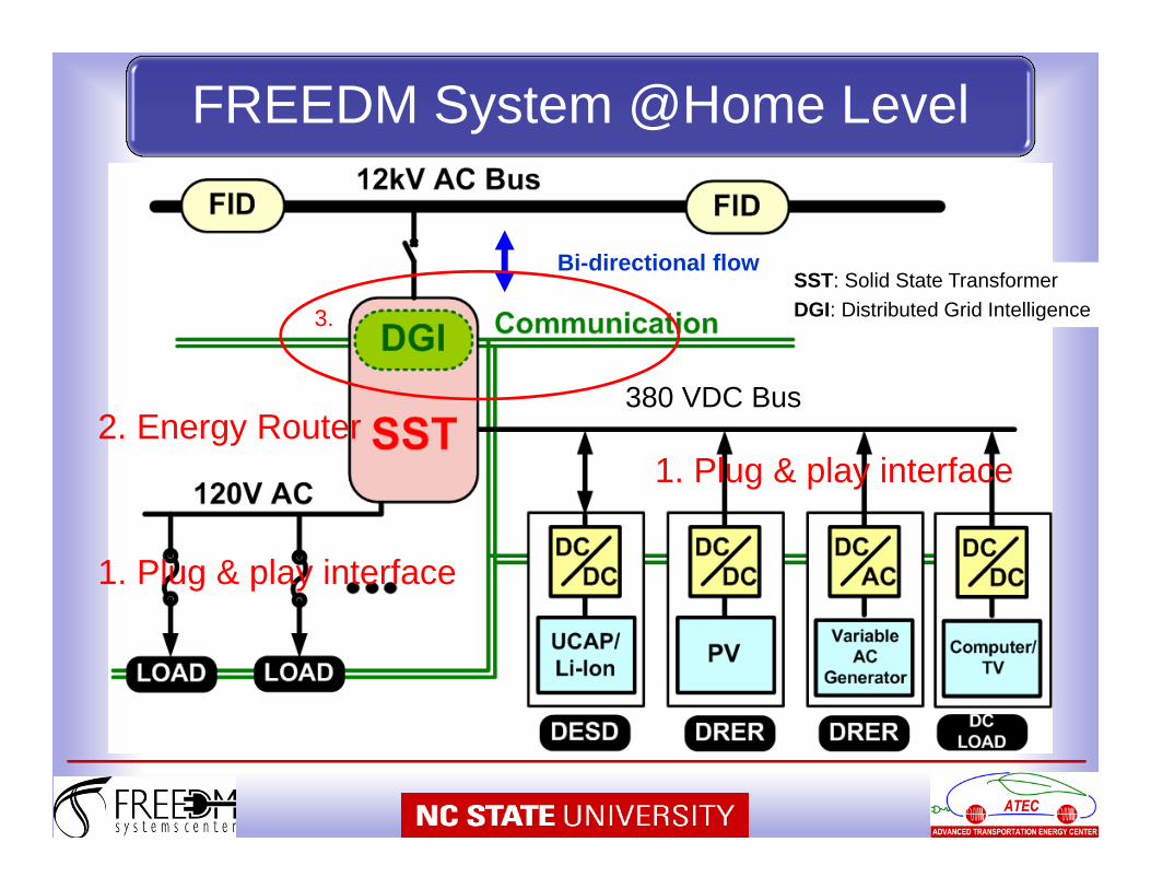
Bi-directional flow
1. Plug & play interface2. Energy Router
1. Plug & play interface
380 VDC Bus
3.
SST: Solid State Transformer DGI: Distributed Grid Intelligence
FREEDM System @Home Level
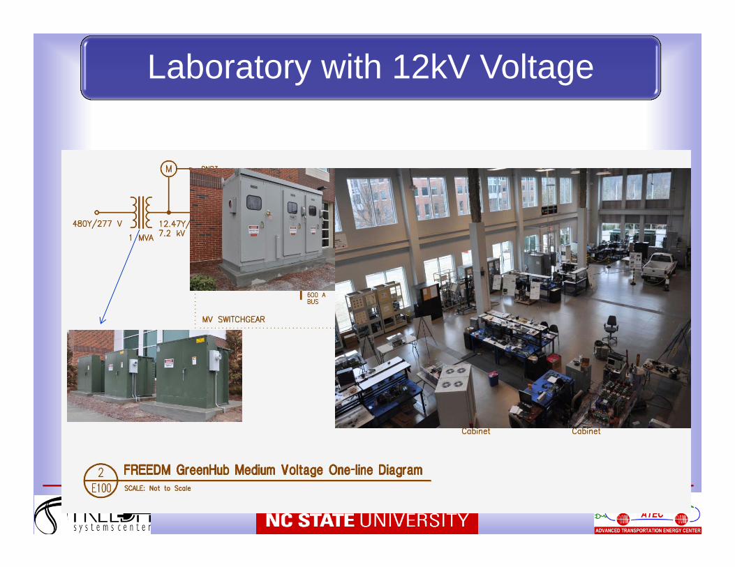
Laboratory with 12kV Voltage

6
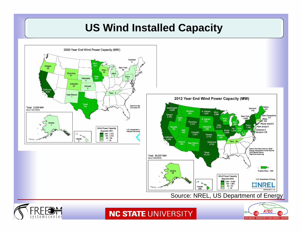
US Wind Installed Capacity
Source: NREL, US Department of Energy
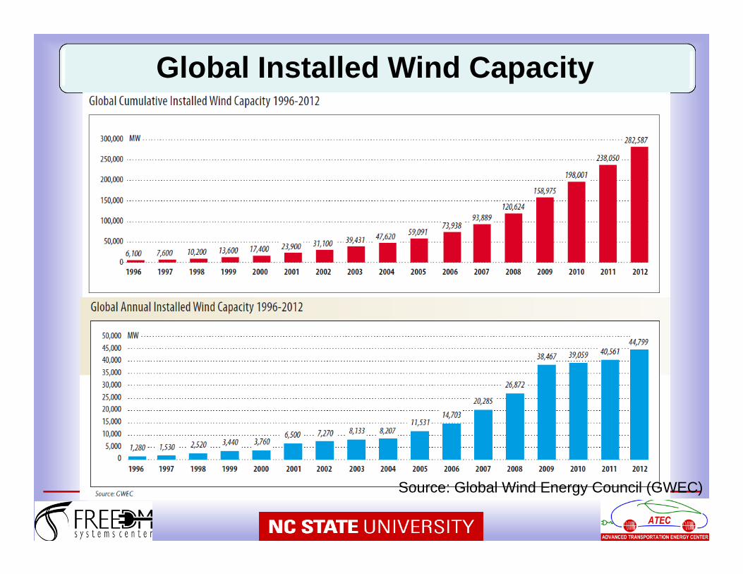
Global Installed Wind Capacity
Source: Global Wind Energy Council (GWEC)
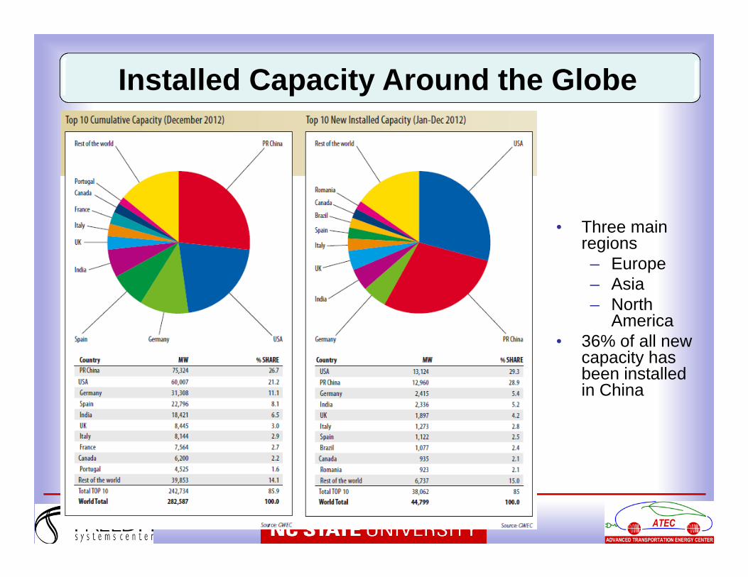
• Three main regions– Europe– Asia– North
America• 36% of all new
capacity has been installed in China
Installed Capacity Around the Globe
• Trend -> Huge offshore wind farms (in GW range) with increased turbine output power
• Offshore Advantage– Large areas available– Higher and more constant wind speed than onshore– Higher energy yield (about 40% more than onshore)
• Challenges– High cost of installation and maintenance– Cost for grid connection– Energy Storage– Accessibility of offshore installations– Legislative issues
Offshore Wind Power
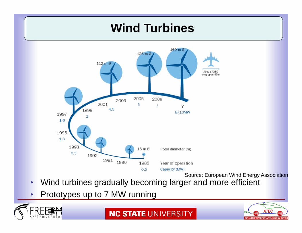
• Wind turbines gradually becoming larger and more efficient• Prototypes up to 7 MW running
Source: European Wind Energy Association
Wind Turbines
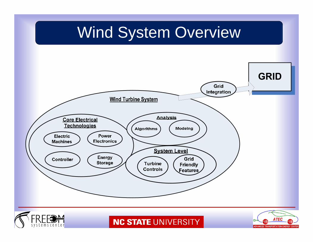
Wind System Overview
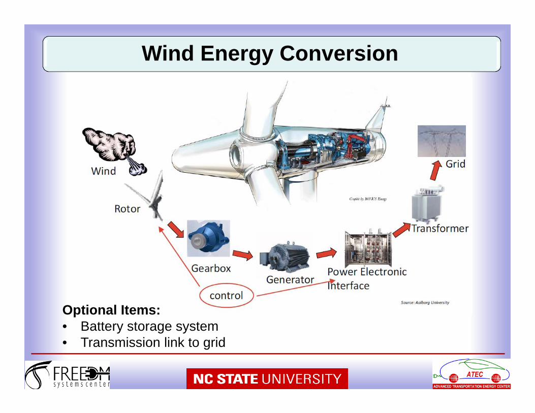
Wind Energy Conversion
Optional Items:• Battery storage system • Transmission link to grid
14
15
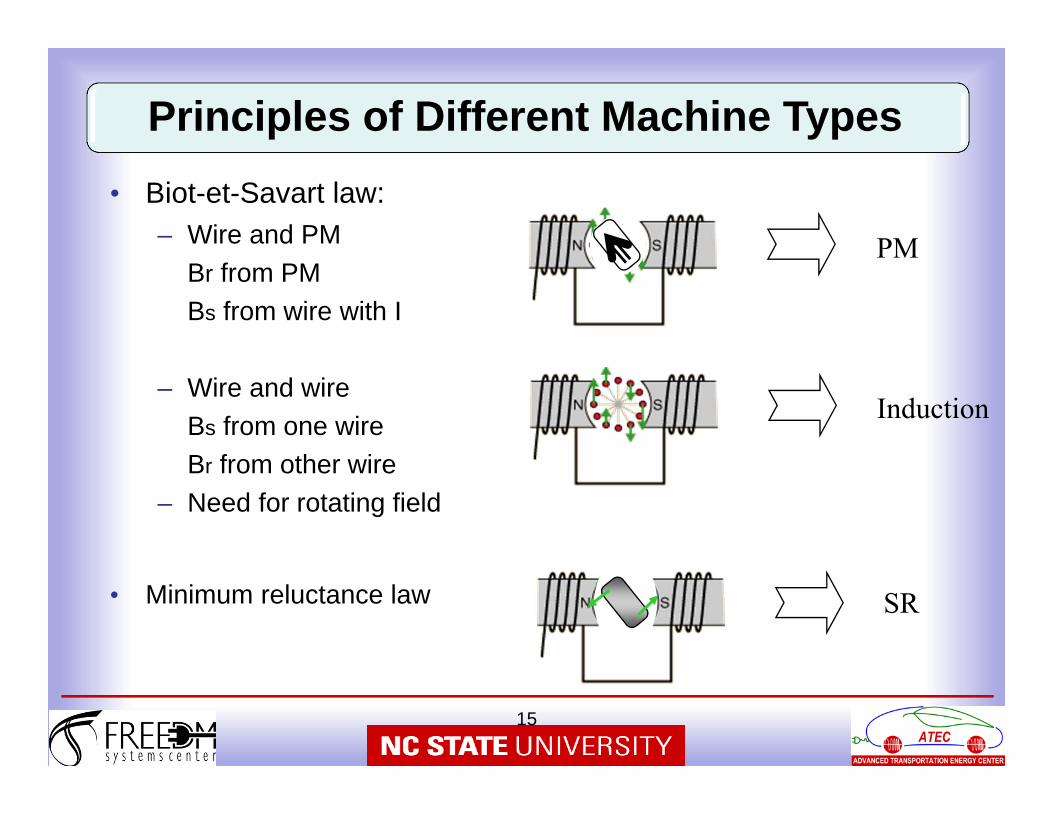
• Biot-et-Savart law:– Wire and PM
Br from PMBs from wire with I
– Wire and wireBs from one wireBr from other wire
– Need for rotating field
• Minimum reluctance law
Induction
PM
SR
Principles of Different Machine Types
16
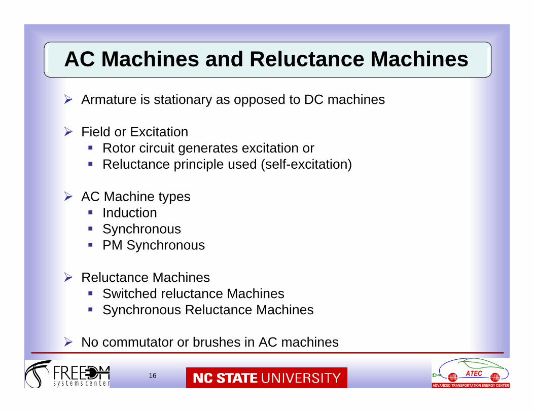
Armature is stationary as opposed to DC machines
Field or Excitation Rotor circuit generates excitation or Reluctance principle used (self-excitation)
AC Machine types Induction Synchronous PM Synchronous
Reluctance Machines Switched reluctance Machines Synchronous Reluctance Machines
No commutator or brushes in AC machines
AC Machines and Reluctance Machines
17
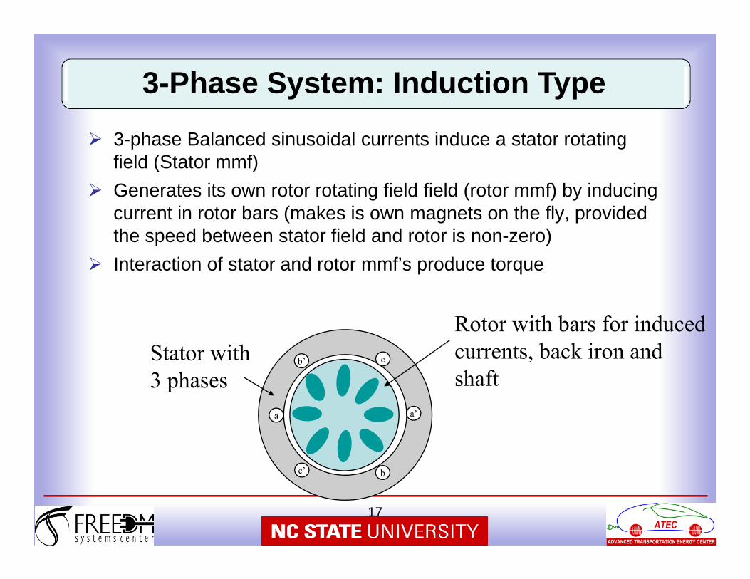
3-phase Balanced sinusoidal currents induce a stator rotating field (Stator mmf)
Generates its own rotor rotating field field (rotor mmf) by inducing current in rotor bars (makes is own magnets on the fly, provided the speed between stator field and rotor is non-zero)
Interaction of stator and rotor mmf’s produce torque
Stator with 3 phases
Rotor with bars for induced currents, back iron and shaft
a
c’ b
b’ c
a’
3-Phase System: Induction Type
18
x
x
x
x
x
x
x
x
x
x
x
x
xx
xxx
x
x
x
x
xx
x
x
x
x
x
x
xx
x
x
xx
x
x
x
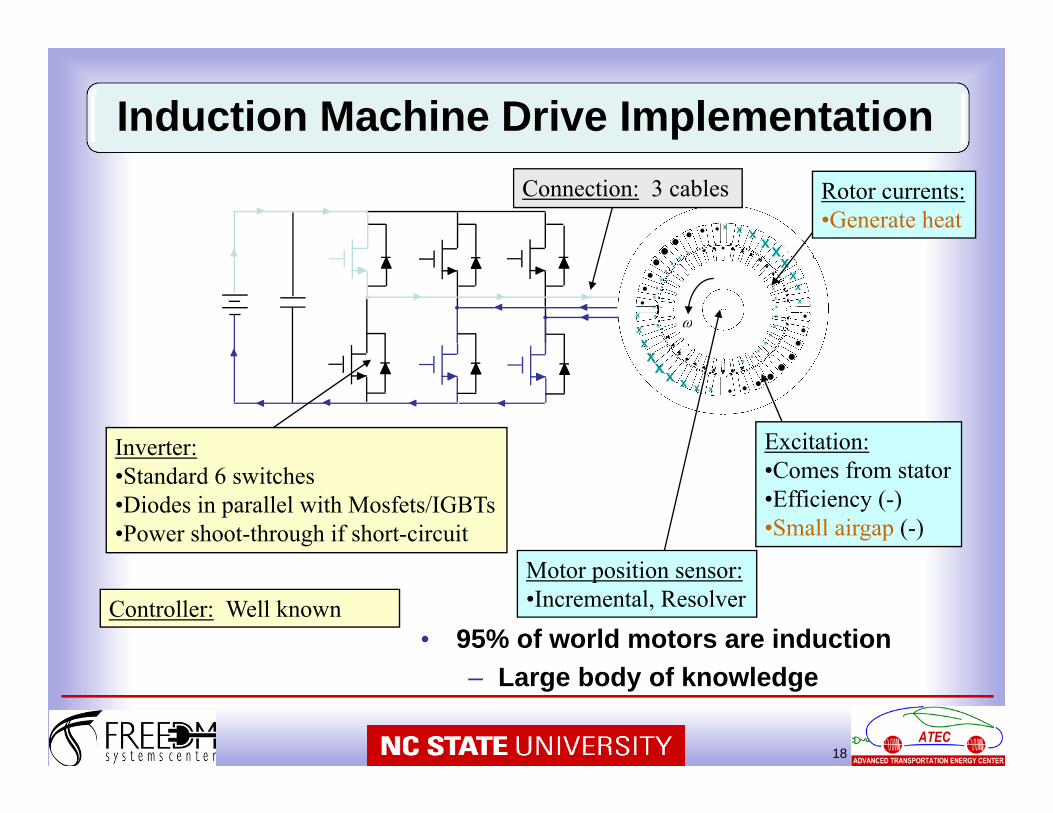
• 95% of world motors are induction– Large body of knowledge
Controller: Well known
Connection: 3 cables
Inverter:•Standard 6 switches•Diodes in parallel with Mosfets/IGBTs•Power shoot-through if short-circuit
Excitation:•Comes from stator•Efficiency (-)•Small airgap (-)
Motor position sensor:•Incremental, Resolver
Rotor currents:•Generate heat
Induction Machine Drive Implementation
19
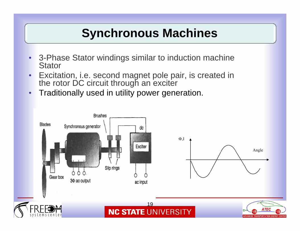
• 3-Phase Stator windings similar to induction machine Stator
• Excitation, i.e. second magnet pole pair, is created in the rotor DC circuit through an exciter
• Traditionally used in utility power generation.
Angle
,I
Synchronous Machines
20
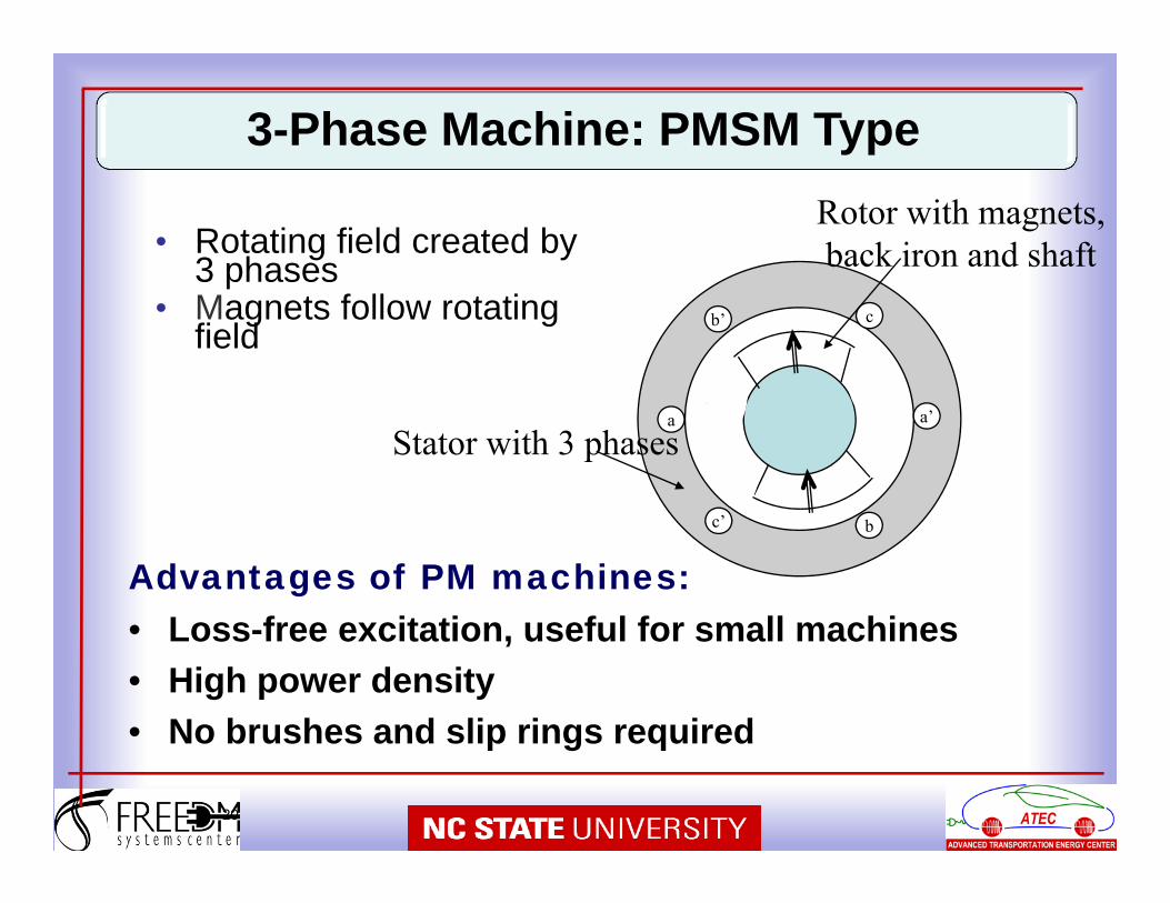
• Rotating field created by 3 phases
• Magnets follow rotating field
a
c’ b
b’ c
a’
Stator with 3 phases
Rotor with magnets, back iron and shaft
Advantages of PM machines:• Loss-free excitation, useful for small machines• High power density• No brushes and slip rings required
3-Phase Machine: PMSM Type
21
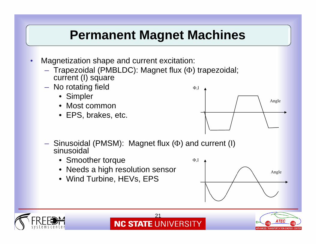
• Magnetization shape and current excitation:– Trapezoidal (PMBLDC): Magnet flux () trapezoidal;
current (I) square– No rotating field
• Simpler• Most common• EPS, brakes, etc.
– Sinusoidal (PMSM): Magnet flux () and current (I) sinusoidal
• Smoother torque• Needs a high resolution sensor • Wind Turbine, HEVs, EPS
Angle
,I
Angle
,I
Permanent Magnet Machines
22
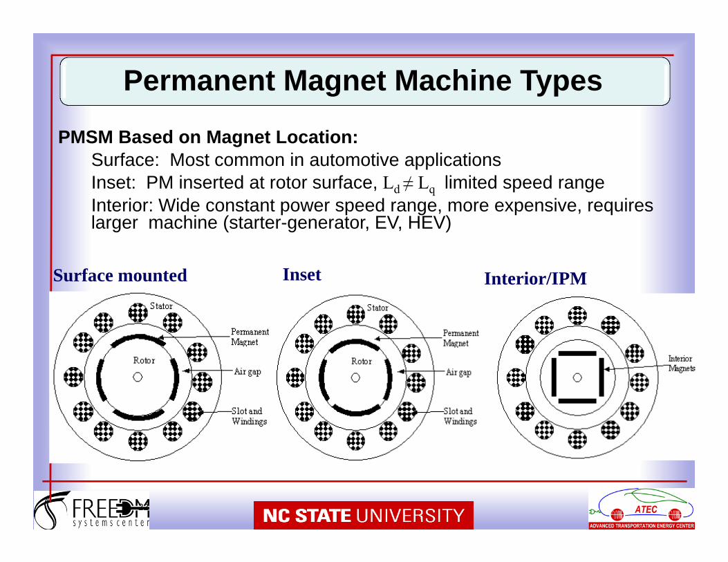
Surface mounted Inset Interior/IPM
PMSM Based on Magnet Location:Surface: Most common in automotive applicationsInset: PM inserted at rotor surface, Ld ≠ Lq limited speed rangeInterior: Wide constant power speed range, more expensive, requires larger machine (starter-generator, EV, HEV)
Permanent Magnet Machine Types
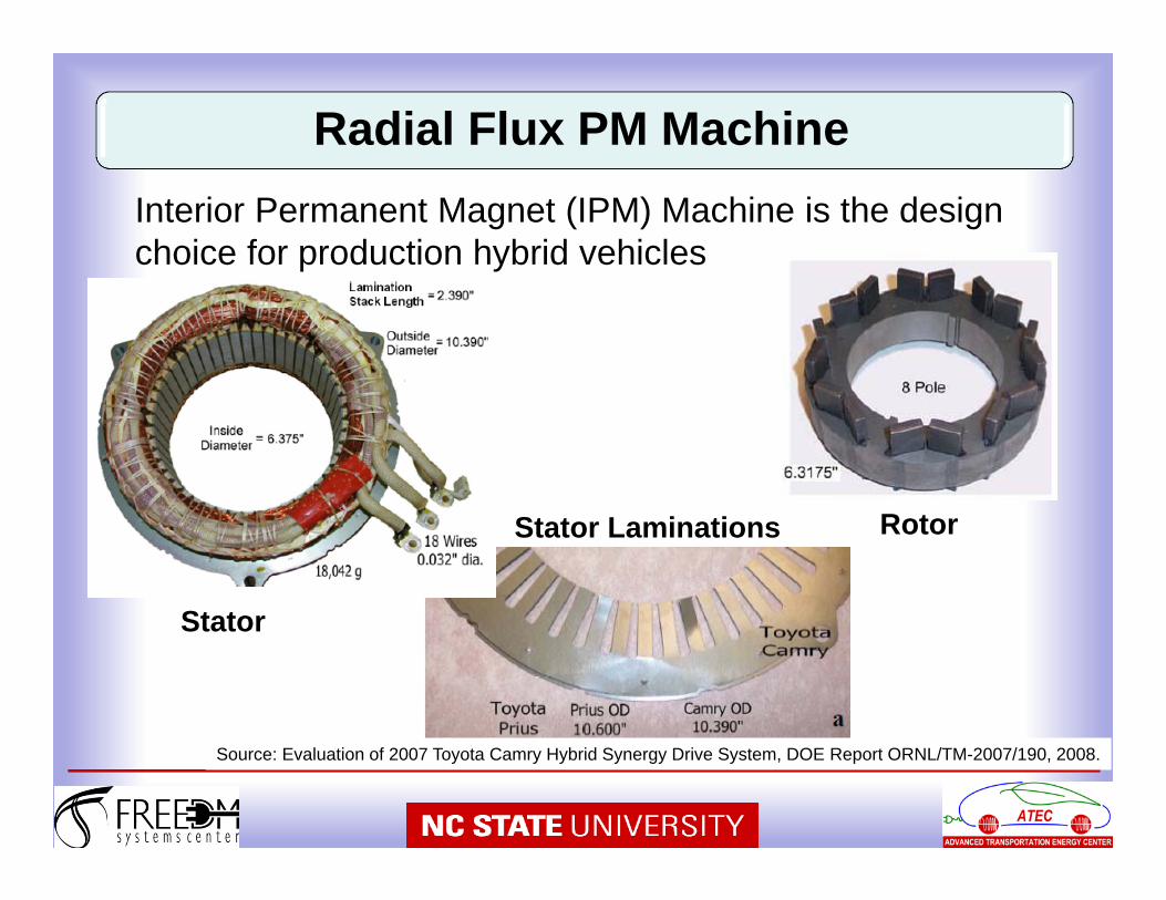
Stator
RotorStator Laminations
Source: Evaluation of 2007 Toyota Camry Hybrid Synergy Drive System, DOE Report ORNL/TM-2007/190, 2008.
Interior Permanent Magnet (IPM) Machine is the design choice for production hybrid vehicles
Radial Flux PM Machine
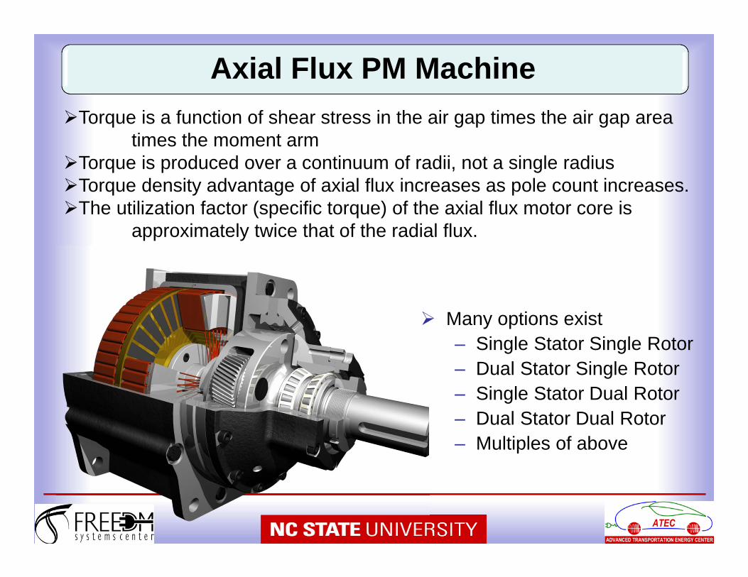
Many options exist– Single Stator Single Rotor– Dual Stator Single Rotor– Single Stator Dual Rotor– Dual Stator Dual Rotor– Multiples of above
Torque is a function of shear stress in the air gap times the air gap area times the moment arm
Torque is produced over a continuum of radii, not a single radiusTorque density advantage of axial flux increases as pole count increases.The utilization factor (specific torque) of the axial flux motor core is
approximately twice that of the radial flux.
Axial Flux PM Machine
25
Fs
Fr
N
N
N
S
S
S
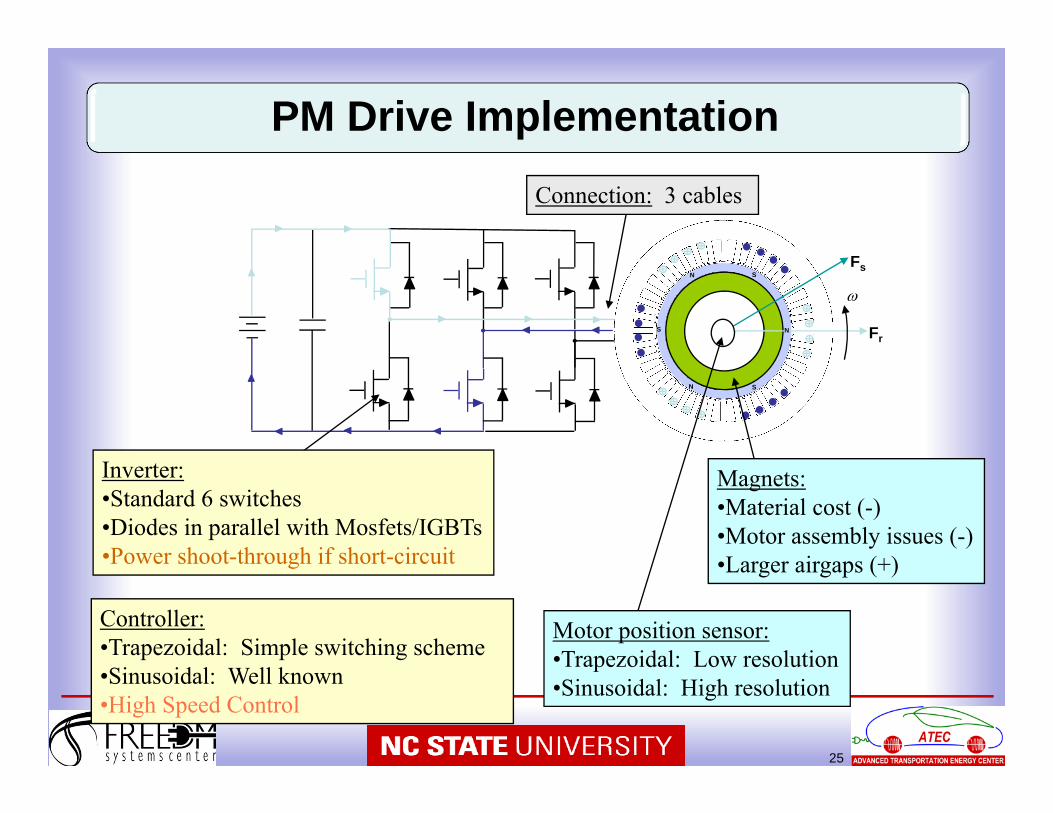
Motor position sensor:•Trapezoidal: Low resolution•Sinusoidal: High resolution
Controller:•Trapezoidal: Simple switching scheme•Sinusoidal: Well known•High Speed Control
Inverter:•Standard 6 switches•Diodes in parallel with Mosfets/IGBTs•Power shoot-through if short-circuit
Magnets:•Material cost (-)•Motor assembly issues (-)•Larger airgaps (+)
Connection: 3 cables
PM Drive Implementation
,2,,
,2,,
,,,
ifEifDfCfB
imEimDmCmB
fAmAi
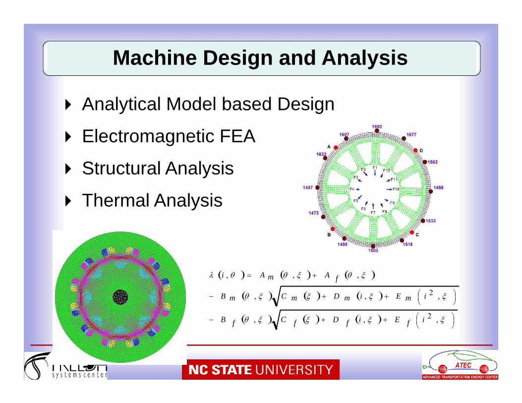
Analytical Model based Design
Electromagnetic FEA
Structural Analysis
Thermal Analysis
Machine Design and Analysis
27
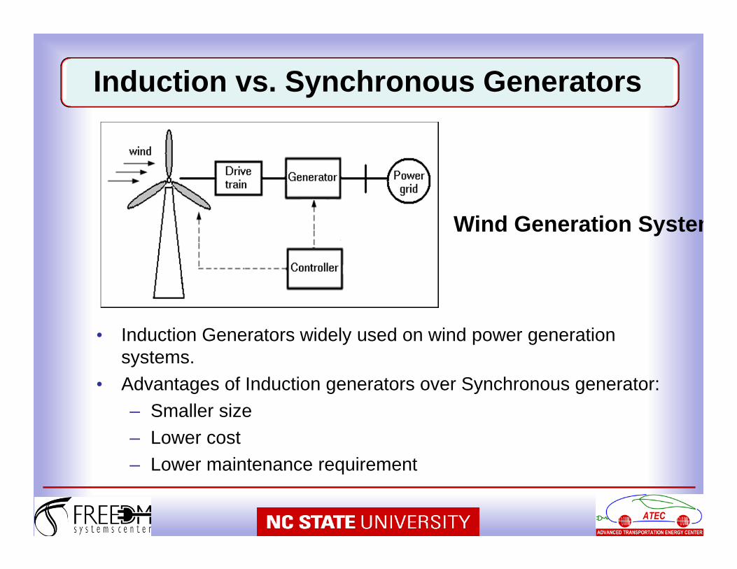
• Induction Generators widely used on wind power generation systems.
• Advantages of Induction generators over Synchronous generator:– Smaller size– Lower cost– Lower maintenance requirement
Induction vs. Synchronous Generators
Wind Generation System

• Two types of induction generators– Squirrel-Cage Induction Generator (SCIG)
• Fixed speed– Doubly-Fed Induction Generator (DFIG)
• Variable speed
Induction Generators
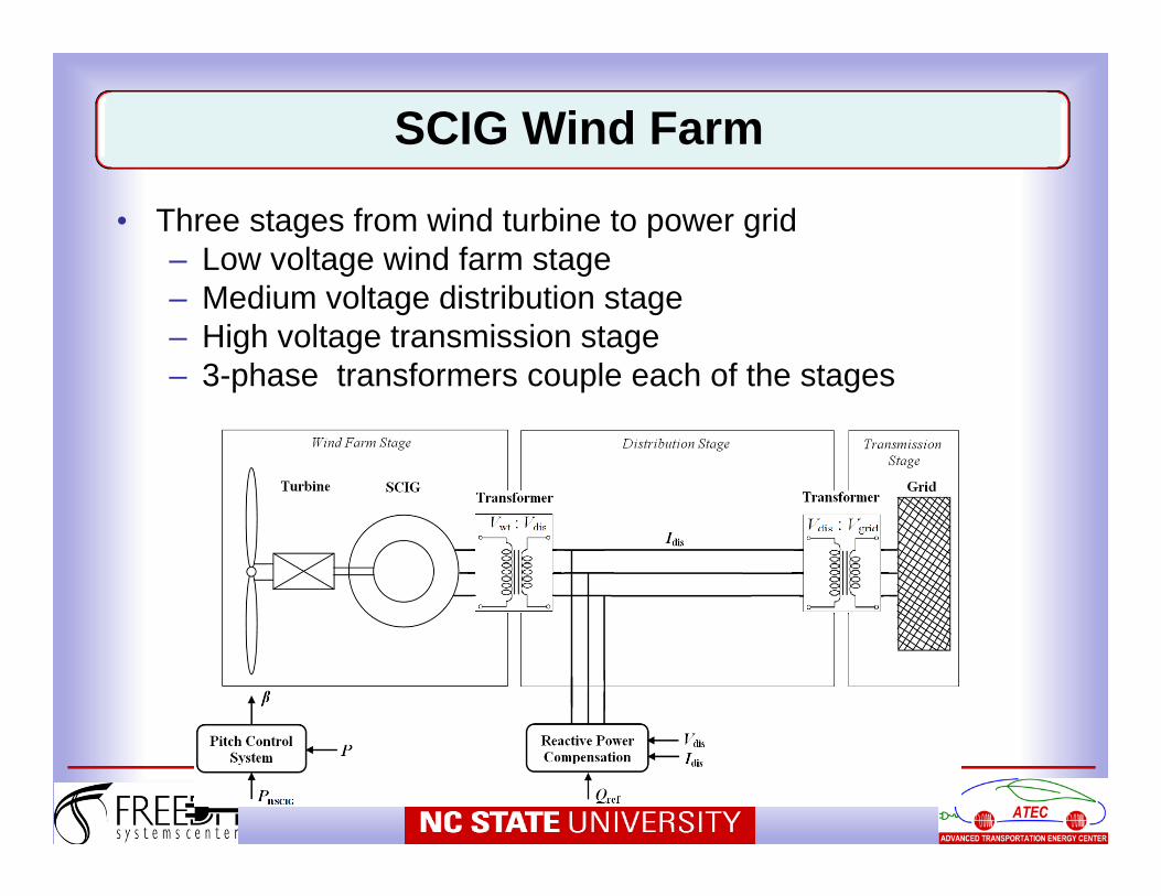
• Three stages from wind turbine to power grid– Low voltage wind farm stage– Medium voltage distribution stage– High voltage transmission stage– 3-phase transformers couple each of the stages
SCIG Wind Farm
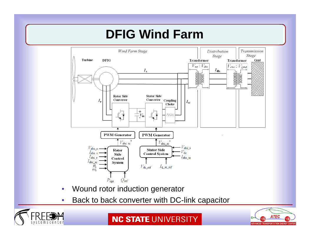
• Wound rotor induction generator• Back to back converter with DC-link capacitor
DFIG Wind Farm
• Doubly-Fed Induction Generator – With variable speed capability has higher
energy capture efficiency and improved power quality
– Back to back converter, which consists of two bidirectional converters and dc-link, acts as an optimal operation tracking interface
– Field orientation is applied to both stator- and rotor-side converters to achieve desirable control on voltage and power
Doubly Fed Induction Generator (DFIG)
• Typical voltage levels:– Low Voltage (LV): 690V– Medium Voltage (MV): 3kV to 13.8kV
• MV Advantages– Lower loss connection between generator and
converter– Power electronics can be placed in tower– Reduction of volume and weight of nacelle– Increased efficiency
• LV Advantages– Less expensive generator, since MV insulation is not
required– MV personnel training not required
WT Generator Voltage Levels
• Advantages:– Reduction of mechanical stress due to the weak
grid coupling– Utilization of synchronous generators possible– Turbine acts as intermediate storage of kinetic
energy during gusts– Less pulsation of output power– Ride-through of grid faults– Efficiency gain at low wind due to adaptation of
turbine speed– Less noise at low wind speed
• Drawback: – Power Electronics is needed
WT Variable Speed Operation

• Electrically excited Synchronous Gen.– Gearless– Low-speed multi-pole
generator– Large weight of nacelle– Power up to 6MW
• Direct-drive PMSG– Low-speed generator– Reduced size and weight– Power up to 3.5MW
Source: ECCE 2010 Tutorial on Grid Converters for PV and WT Systems by Prof. R. W. De Doncker, RWTH Aachen, Germany
Wind Turbines at Variable Speeds
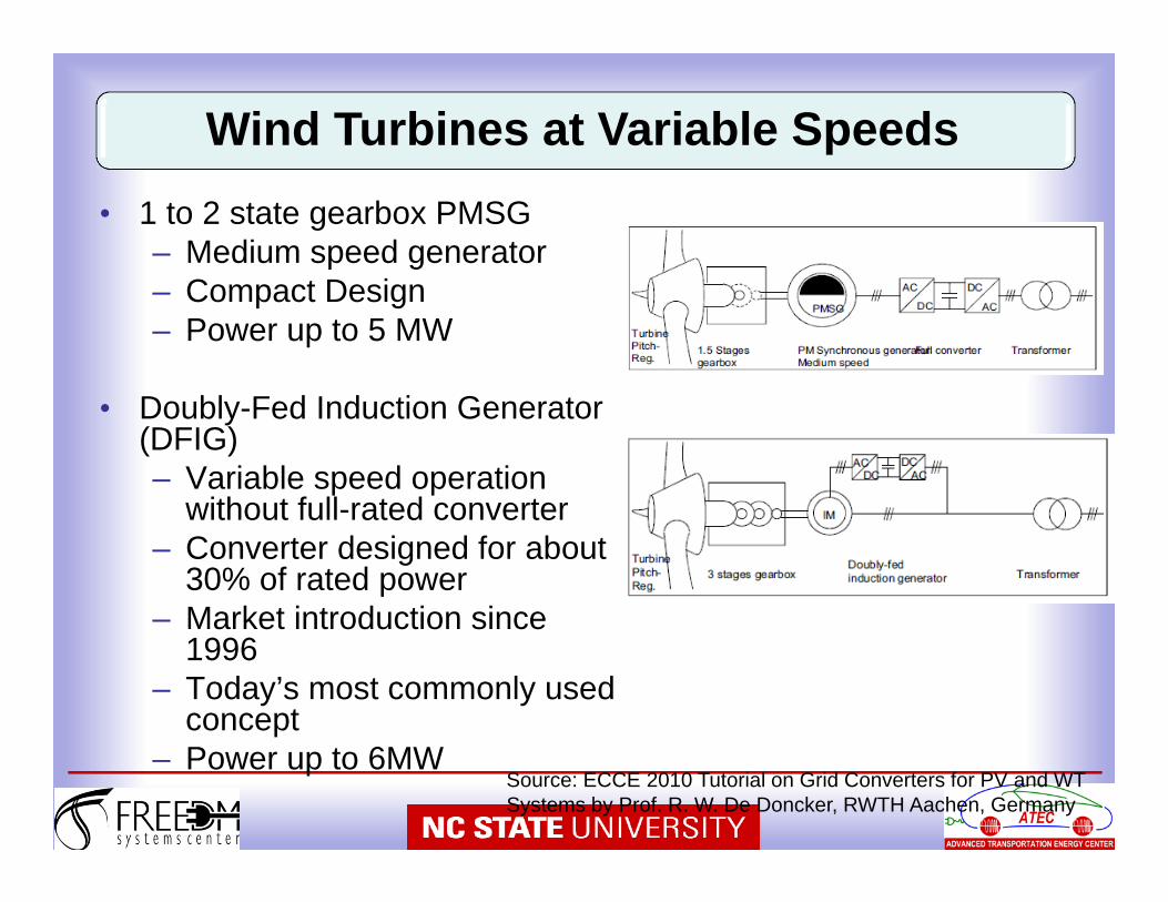
• 1 to 2 state gearbox PMSG– Medium speed generator– Compact Design– Power up to 5 MW
• Doubly-Fed Induction Generator (DFIG)– Variable speed operation
without full-rated converter– Converter designed for about
30% of rated power– Market introduction since
1996– Today’s most commonly used
concept– Power up to 6MW
Source: ECCE 2010 Tutorial on Grid Converters for PV and WT Systems by Prof. R. W. De Doncker, RWTH Aachen, Germany
Wind Turbines at Variable Speeds
• Partial Converter with DFIG– Small inverter needed in theory– Reduction of power electronic losses– Not fully decoupled generator from the grid
• Full converter – Increased power quality and very flexible reactive
power control– Converter needs to be designed for full power– Higher efficiency of generator
• Grid interconnection rules in the future will govern the choice
Partial Converter vs. Full Converter
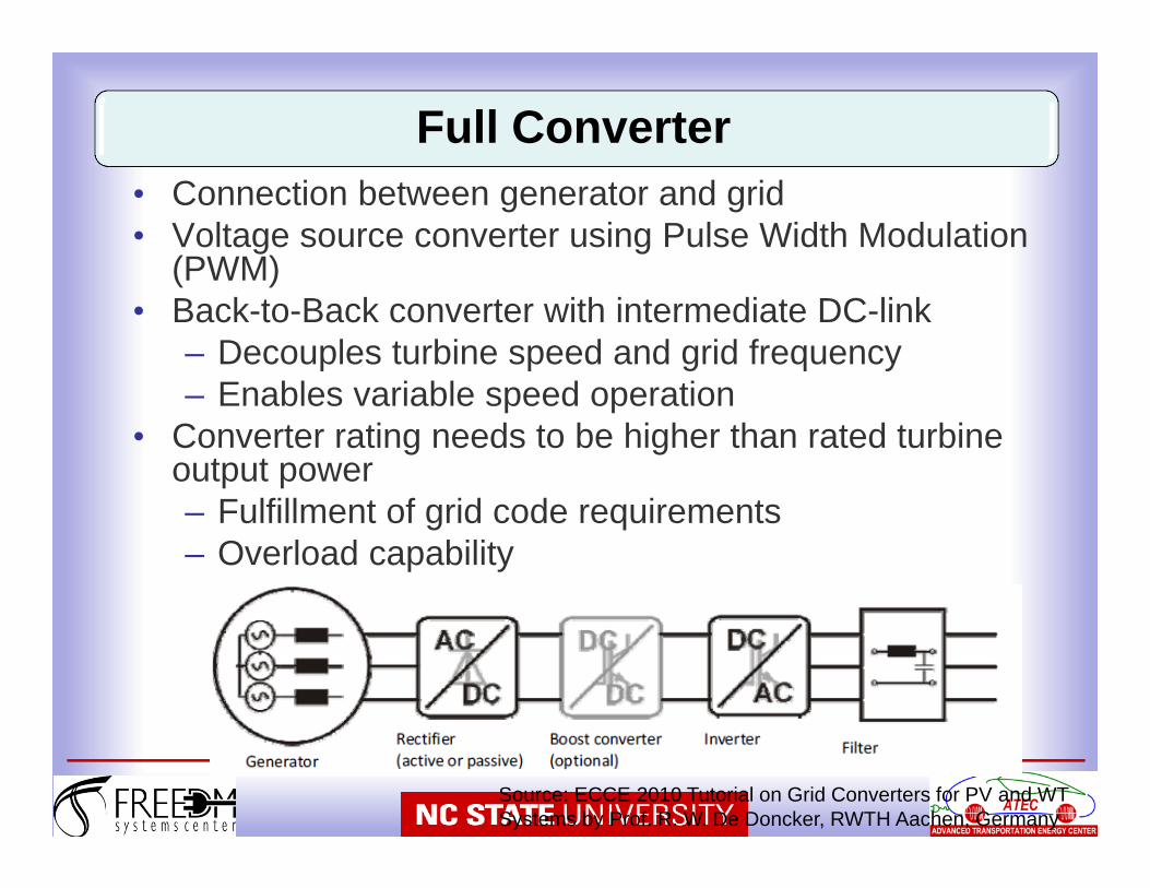
• Connection between generator and grid• Voltage source converter using Pulse Width Modulation
(PWM)• Back-to-Back converter with intermediate DC-link
– Decouples turbine speed and grid frequency– Enables variable speed operation
• Converter rating needs to be higher than rated turbine output power– Fulfillment of grid code requirements– Overload capability
Full Converter
Source: ECCE 2010 Tutorial on Grid Converters for PV and WT Systems by Prof. R. W. De Doncker, RWTH Aachen, Germany
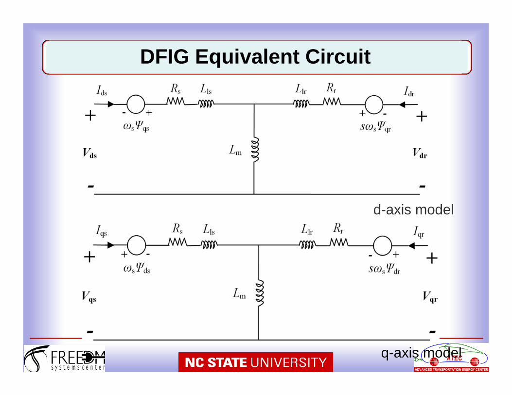
d-axis model
q-axis model
DFIG Equivalent Circuit
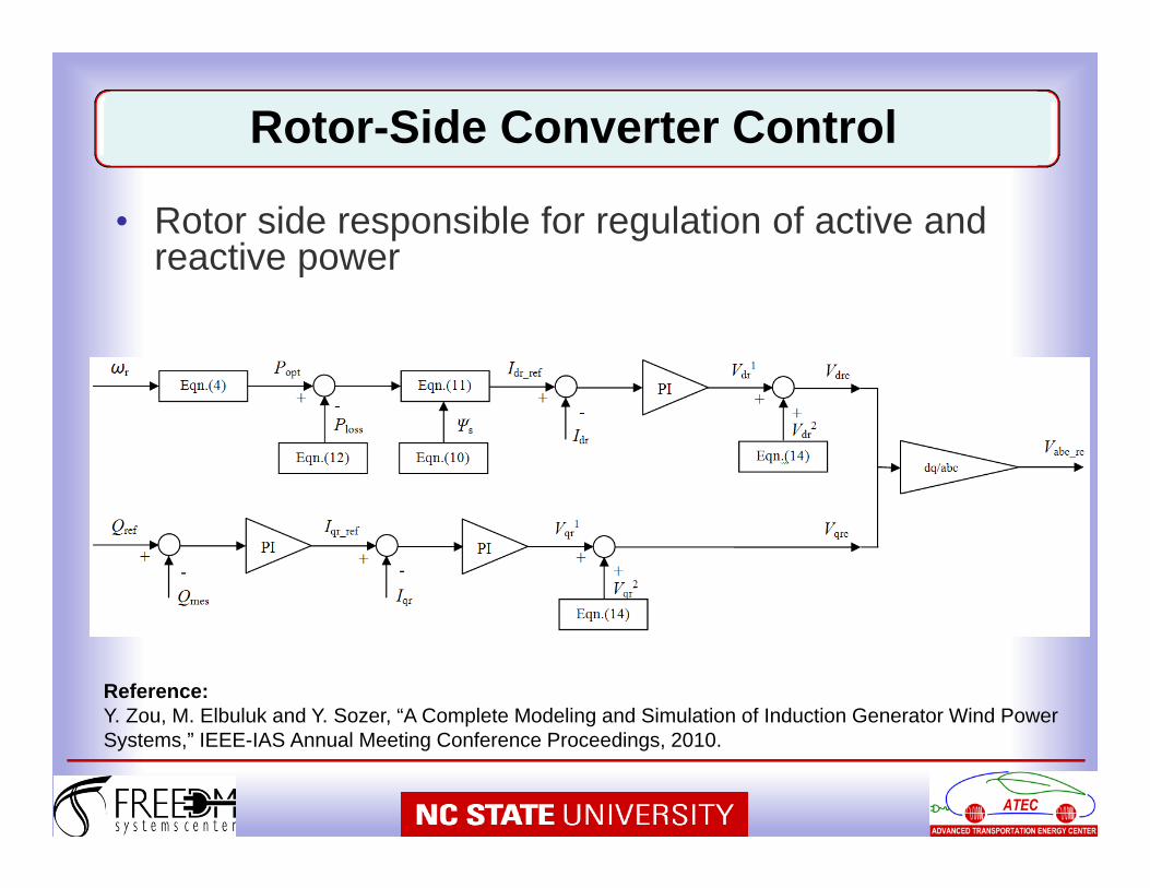
• Rotor side responsible for regulation of active and reactive power
Rotor-Side Converter Control
Reference:Y. Zou, M. Elbuluk and Y. Sozer, “A Complete Modeling and Simulation of Induction Generator Wind Power Systems,” IEEE-IAS Annual Meeting Conference Proceedings, 2010.
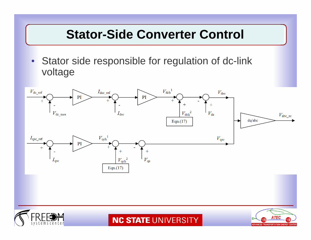
• Stator side responsible for regulation of dc-link voltage
Stator-Side Converter Control

42
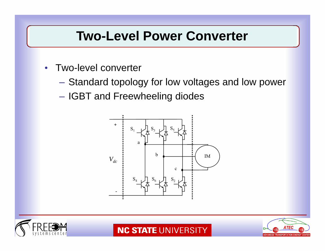
• Two-level converter– Standard topology for low voltages and low power– IGBT and Freewheeling diodes
Two-Level Power Converter
S1 S3 S5
S4 S6 S2
-
+
VdcIM
a
b
c
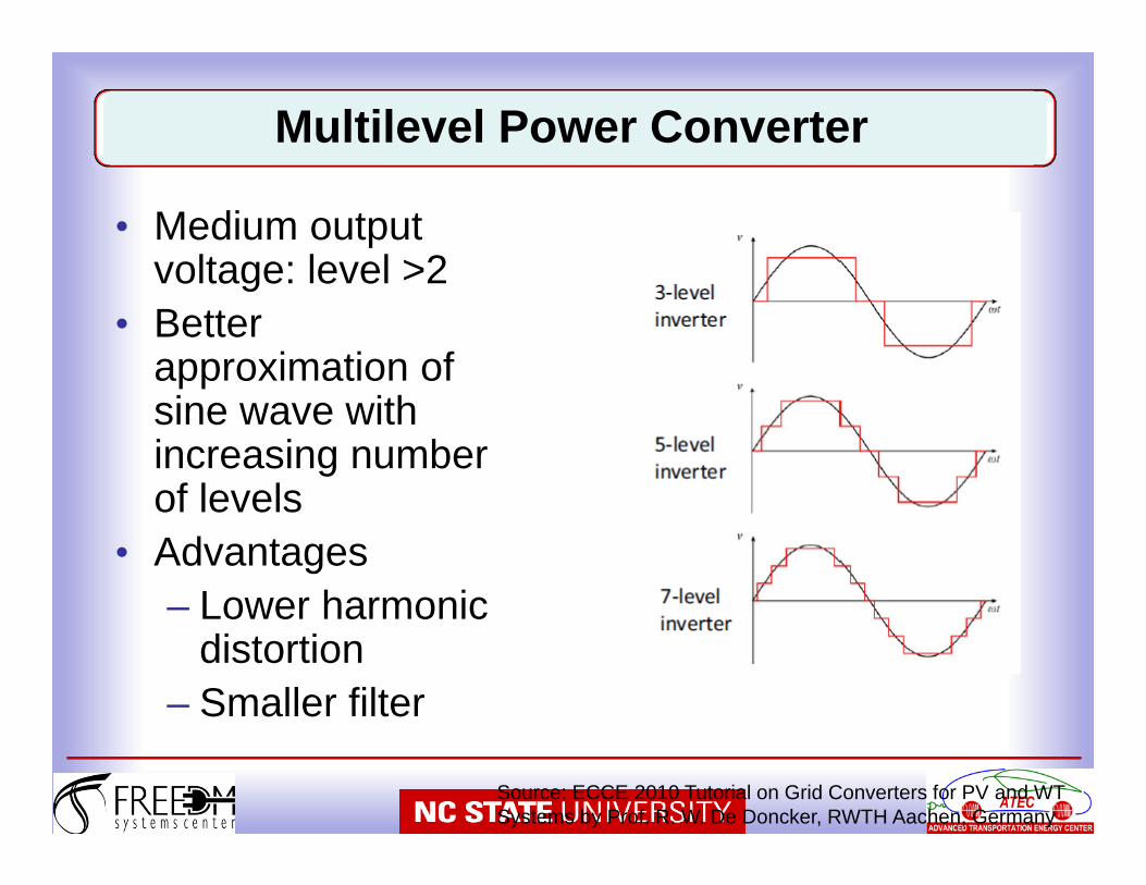
• Medium output voltage: level >2
• Better approximation of sine wave with increasing number of levels
• Advantages– Lower harmonic
distortion– Smaller filter
Multilevel Power Converter
Source: ECCE 2010 Tutorial on Grid Converters for PV and WT Systems by Prof. R. W. De Doncker, RWTH Aachen, Germany
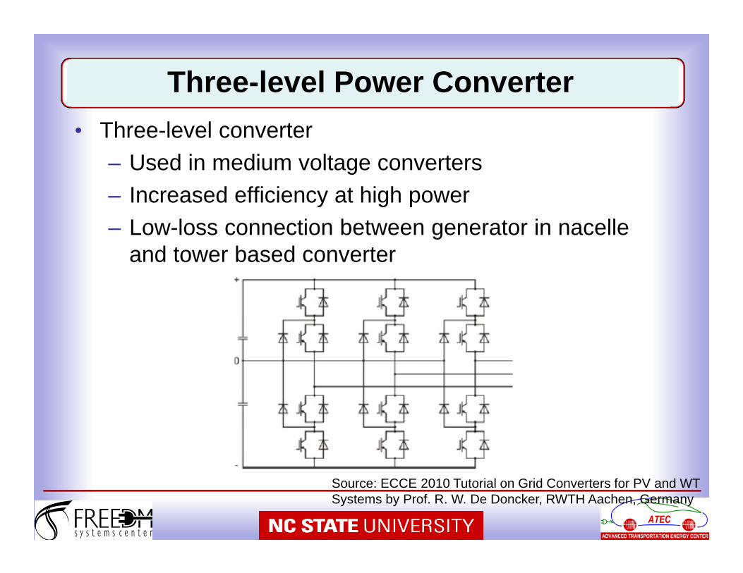
• Three-level converter– Used in medium voltage converters– Increased efficiency at high power– Low-loss connection between generator in nacelle
and tower based converter
Source: ECCE 2010 Tutorial on Grid Converters for PV and WT Systems by Prof. R. W. De Doncker, RWTH Aachen, Germany
Three-level Power Converter
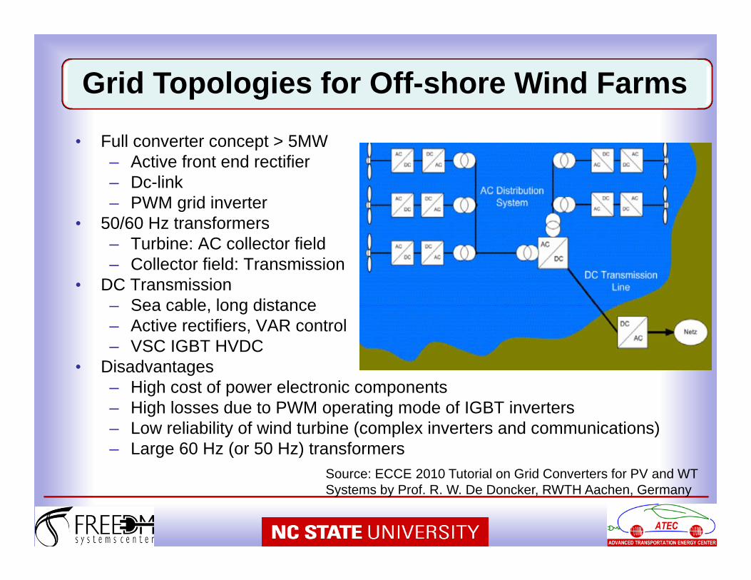
• Full converter concept > 5MW– Active front end rectifier– Dc-link– PWM grid inverter
• 50/60 Hz transformers– Turbine: AC collector field– Collector field: Transmission
• DC Transmission– Sea cable, long distance– Active rectifiers, VAR control– VSC IGBT HVDC
• Disadvantages– High cost of power electronic components– High losses due to PWM operating mode of IGBT inverters– Low reliability of wind turbine (complex inverters and communications)– Large 60 Hz (or 50 Hz) transformers
Source: ECCE 2010 Tutorial on Grid Converters for PV and WT Systems by Prof. R. W. De Doncker, RWTH Aachen, Germany
Grid Topologies for Off-shore Wind Farms
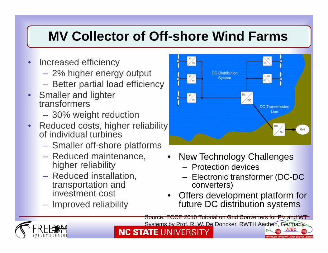
• Increased efficiency– 2% higher energy output– Better partial load efficiency
• Smaller and lighter transformers– 30% weight reduction
• Reduced costs, higher reliability of individual turbines– Smaller off-shore platforms– Reduced maintenance,
higher reliability– Reduced installation,
transportation and investment cost
– Improved reliability
• New Technology Challenges– Protection devices– Electronic transformer (DC-DC
converters)• Offers development platform for
future DC distribution systemsSource: ECCE 2010 Tutorial on Grid Converters for PV and WT Systems by Prof. R. W. De Doncker, RWTH Aachen, Germany
MV Collector of Off-shore Wind Farms
48
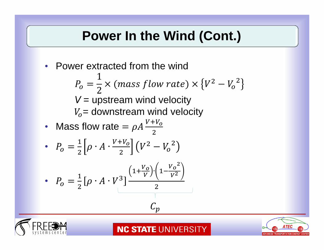
• Power extracted from the wind12
V = upstream wind velocity= downstream wind velocity
• Mass flow rate
• ∙ ∙
• ∙ ∙∙
Power In the Wind (Cont.)
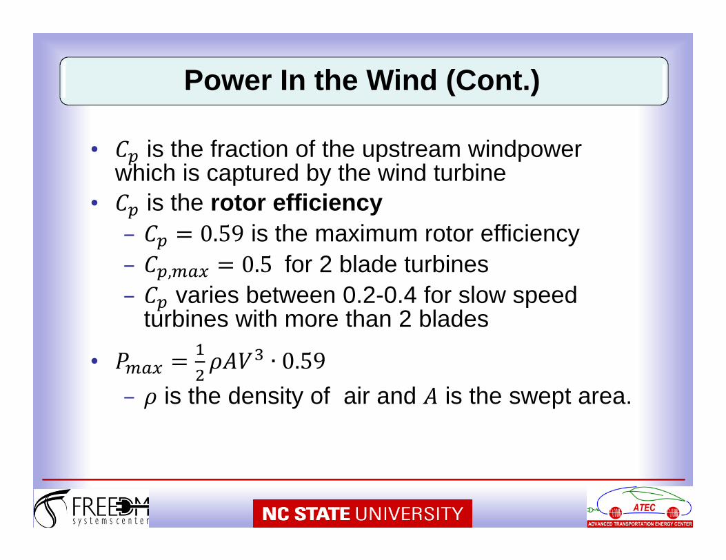
• is the fraction of the upstream windpowerwhich is captured by the wind turbine
• is the rotor efficiencyis the maximum rotor efficiency
, for 2 blade turbinesvaries between 0.2-0.4 for slow speed
turbines with more than 2 blades
•is the density of air and is the swept area.
Power In the Wind (Cont.)
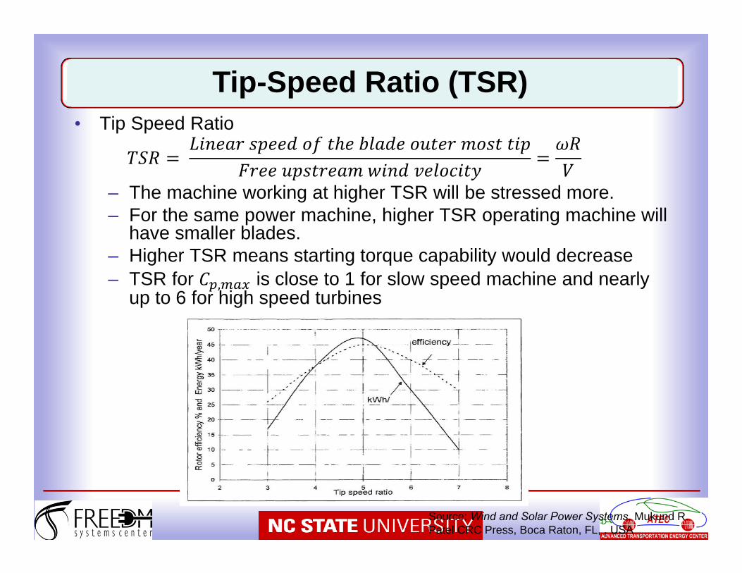
• Tip Speed Ratio
– The machine working at higher TSR will be stressed more. – For the same power machine, higher TSR operating machine will
have smaller blades.– Higher TSR means starting torque capability would decrease– TSR for , is close to 1 for slow speed machine and nearly
up to 6 for high speed turbines
Tip-Speed Ratio (TSR)
Source: Wind and Solar Power Systems, Mukund R. Patel CRC Press, Boca Raton, FL, , USA
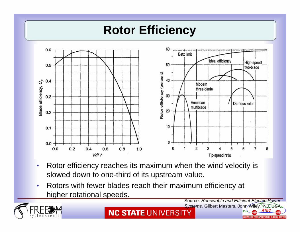
• Rotor efficiency reaches its maximum when the wind velocity is slowed down to one-third of its upstream value.
• Rotors with fewer blades reach their maximum efficiency at higher rotational speeds.
Rotor Efficiency
Source: Renewable and Efficient Electric Power Systems, Gilbert Masters, John Wiley, NJ, USA
• Yaw Control: Continuously orients the rotor in the direction of the wind
• Pitch Control: Changes the pitch of the blade with the changing wind speed to regulate the rotor speed
• Stall Control: When the wind speed exceeds the safe limit it stalls the blades
Turbine Controls
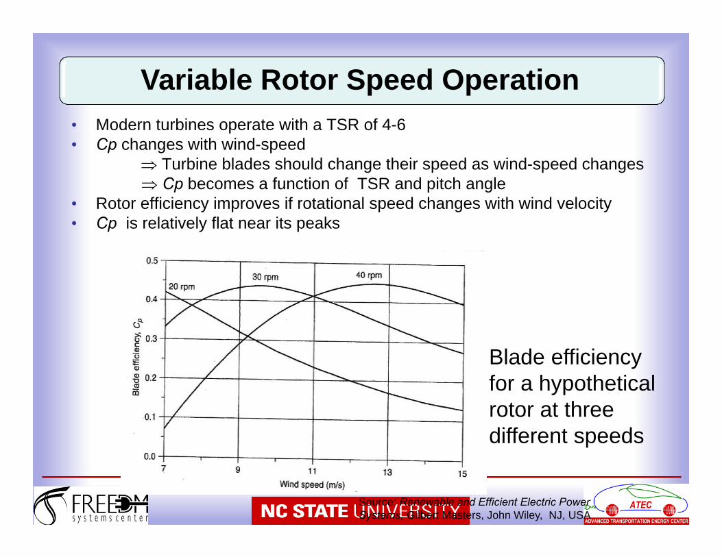
• Modern turbines operate with a TSR of 4-6• Cp changes with wind-speed
Turbine blades should change their speed as wind-speed changes Cp becomes a function of TSR and pitch angle
• Rotor efficiency improves if rotational speed changes with wind velocity• Cp is relatively flat near its peaks
Variable Rotor Speed Operation
Source: Renewable and Efficient Electric Power Systems, Gilbert Masters, John Wiley, NJ, USA
Blade efficiency for a hypothetical rotor at three different speeds
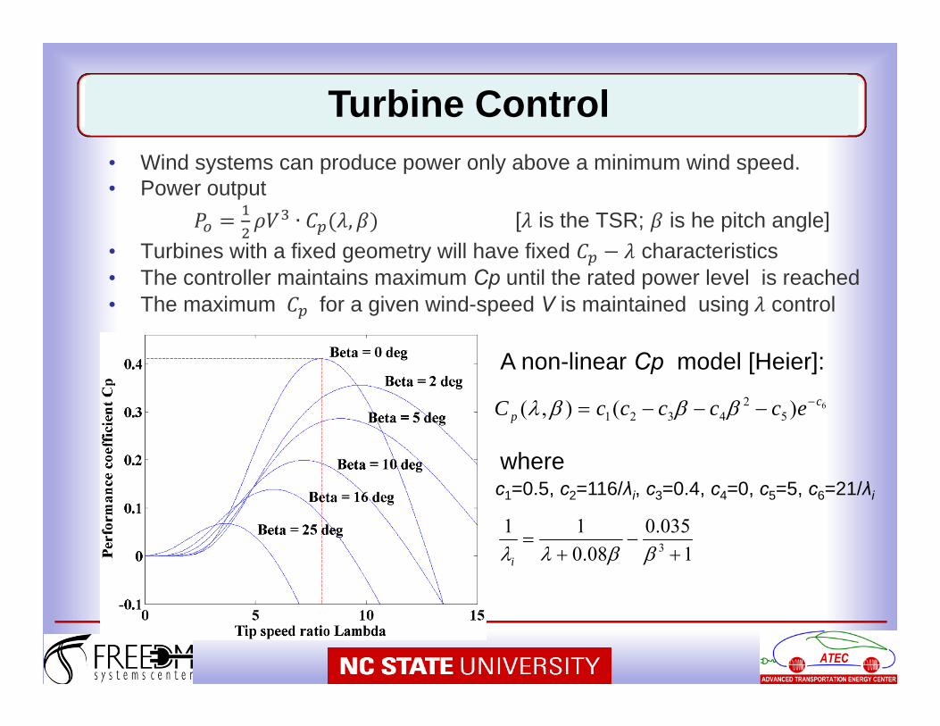
• Wind systems can produce power only above a minimum wind speed.• Power output
∙ , [ is the TSR; is he pitch angle]• Turbines with a fixed geometry will have fixed characteristics• The controller maintains maximum Cp until the rated power level is reached• The maximum for a given wind-speed V is maintained using control
6)(),( 52
4321c
p ecccccC
c1=0.5, c2=116/λi, c3=0.4, c4=0, c5=5, c6=21/λi
1035.0
08.011
3
i
A non-linear Cp model [Heier]:
where
Turbine Control
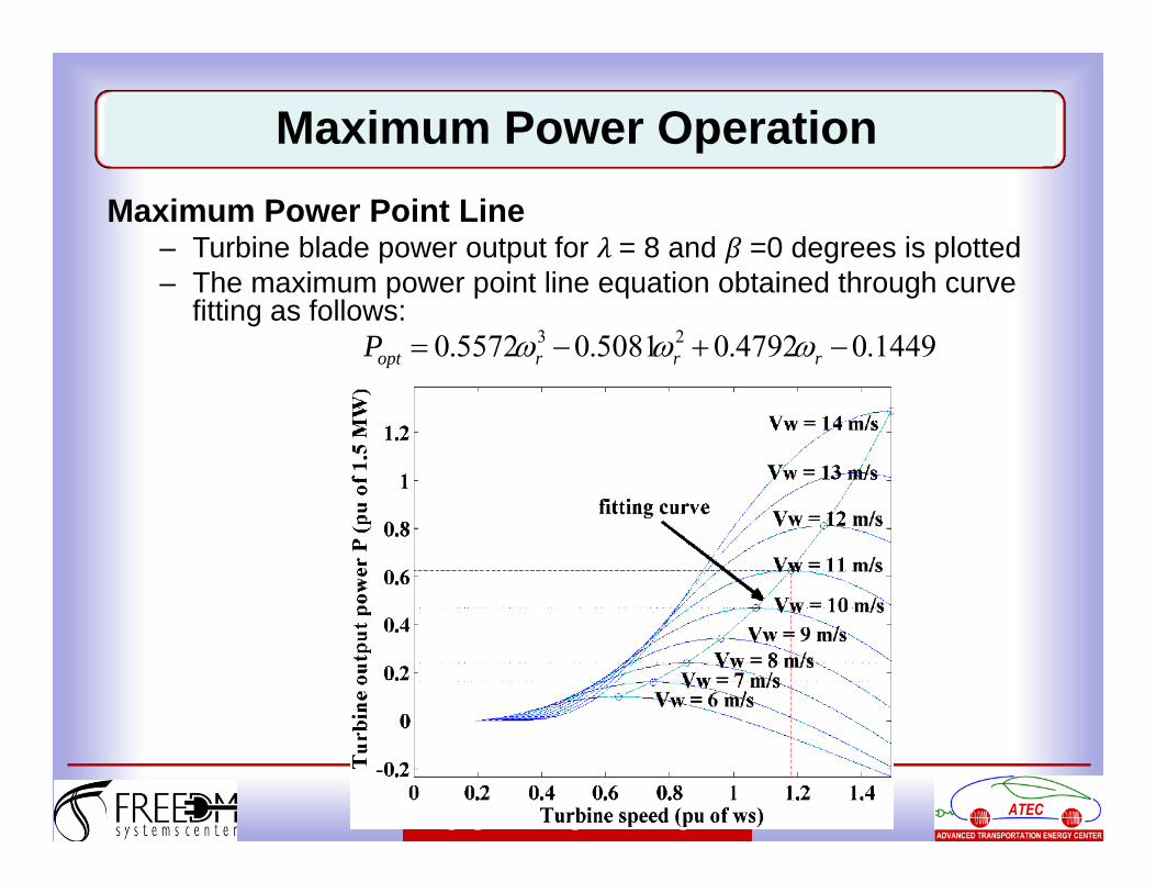
Maximum Power OperationMaximum Power Point Line
– Turbine blade power output for = 8 and =0 degrees is plotted– The maximum power point line equation obtained through curve
fitting as follows:1449.04792.05081.05572.0 23 rrroptP
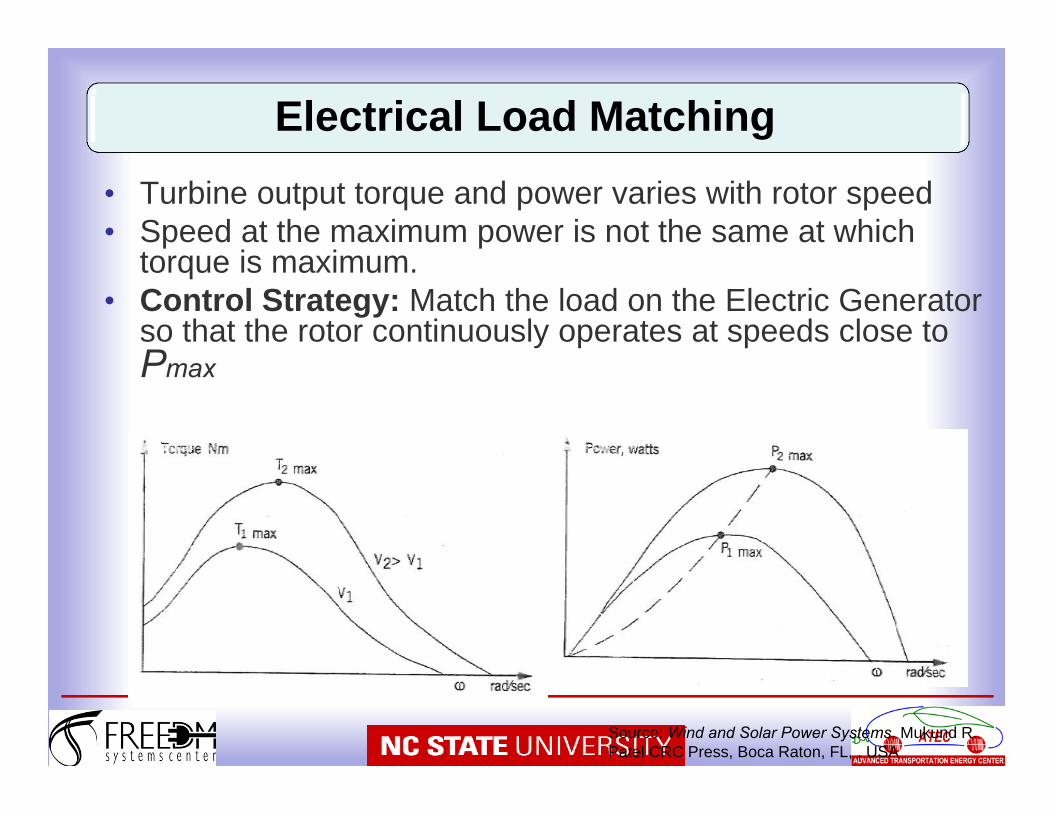
Electrical Load Matching
Source: Wind and Solar Power Systems, Mukund R. Patel CRC Press, Boca Raton, FL, , USA
• Turbine output torque and power varies with rotor speed• Speed at the maximum power is not the same at which
torque is maximum.• Control Strategy: Match the load on the Electric Generator
so that the rotor continuously operates at speeds close to Pmax
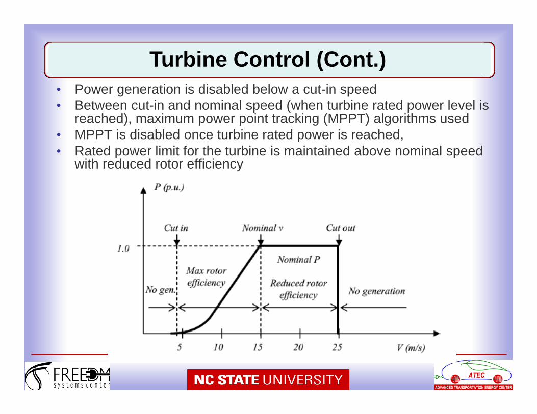
• Power generation is disabled below a cut-in speed• Between cut-in and nominal speed (when turbine rated power level is
reached), maximum power point tracking (MPPT) algorithms used• MPPT is disabled once turbine rated power is reached,• Rated power limit for the turbine is maintained above nominal speed
with reduced rotor efficiency
Turbine Control (Cont.)
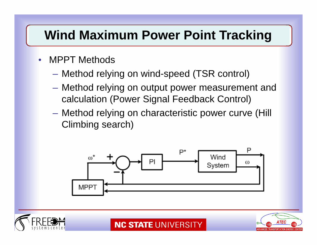
• MPPT Methods– Method relying on wind-speed (TSR control)– Method relying on output power measurement and
calculation (Power Signal Feedback Control)– Method relying on characteristic power curve (Hill
Climbing search)
Wind Maximum Power Point Tracking
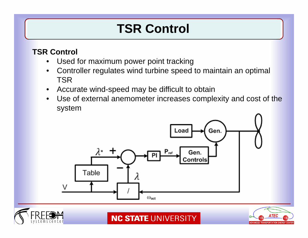
TSR ControlTSR Control
• Used for maximum power point tracking• Controller regulates wind turbine speed to maintain an optimal
TSR• Accurate wind-speed may be difficult to obtain• Use of external anemometer increases complexity and cost of the
system

Power Signal Feedback (PSF) ControlPower Signal Feedback Control
• Requires the knowledge of the turbine maximum power curves• These curves can be obtained from simulation or practical tests• Wind-speed used to select the power curve which gives the
target power to be tracked by the system• In many cases, this power curve can be substituted by the wind-
speed as function of the power and the wind-turbine speed
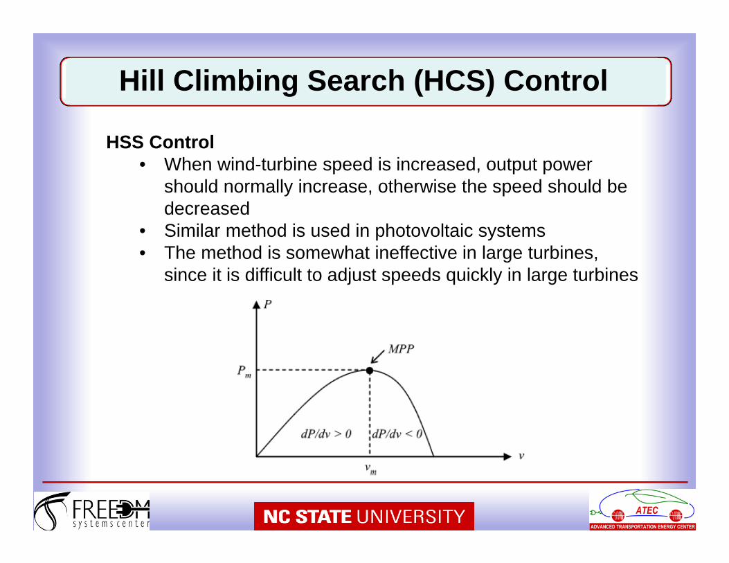
Hill Climbing Search (HCS) Control
HSS Control• When wind-turbine speed is increased, output power
should normally increase, otherwise the speed should be decreased
• Similar method is used in photovoltaic systems• The method is somewhat ineffective in large turbines,
since it is difficult to adjust speeds quickly in large turbines
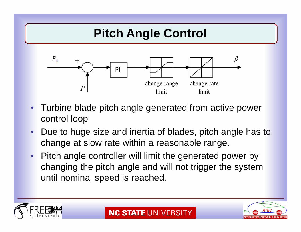
• Turbine blade pitch angle generated from active power control loop
• Due to huge size and inertia of blades, pitch angle has to change at slow rate within a reasonable range.
• Pitch angle controller will limit the generated power by changing the pitch angle and will not trigger the system until nominal speed is reached.
Pitch Angle Control
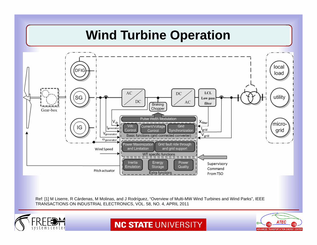
Ref: [1] M Liserre, R Cárdenas, M Molinas, and J Rodríguez, “Overview of Multi-MW Wind Turbines and Wind Parks”, IEEE TRANSACTIONS ON INDUSTRIAL ELECTRONICS, VOL. 58, NO. 4, APRIL 2011
Wind Turbine Operation
Generator side (AC/DC)• DC-Link voltage control or• Active and reactive Power
Control• Generator speed control
(in the outer loop)
Grid side (DC/AC)• DC-Link Voltage and Grid
reactive power control or• Grid active and reactive
power control
Grid Friendly Features:• Generator speed regulation could achieve both maximum
power point operation or power curtailment • Grid support through real and reactive power control.• With generator side DC-Link voltage control, grid support
through low-voltage ride through (LVRT) is possible.
Wind Turbine Operation
66
67
• Variability in power generation with renewable energy sources
• Adding energy storage eliminates the variability, but increases cost
• Control of power flow to grid and to/from the storage system depending on the wind situation and grid demand.
• Grid connection and synchronization in the presence of impurity (harmonics, voltage unbalance).
• Fast delivery of reactive power to the HV transmission network overcoming high cable impedances.
Grid Integration Challenges
68
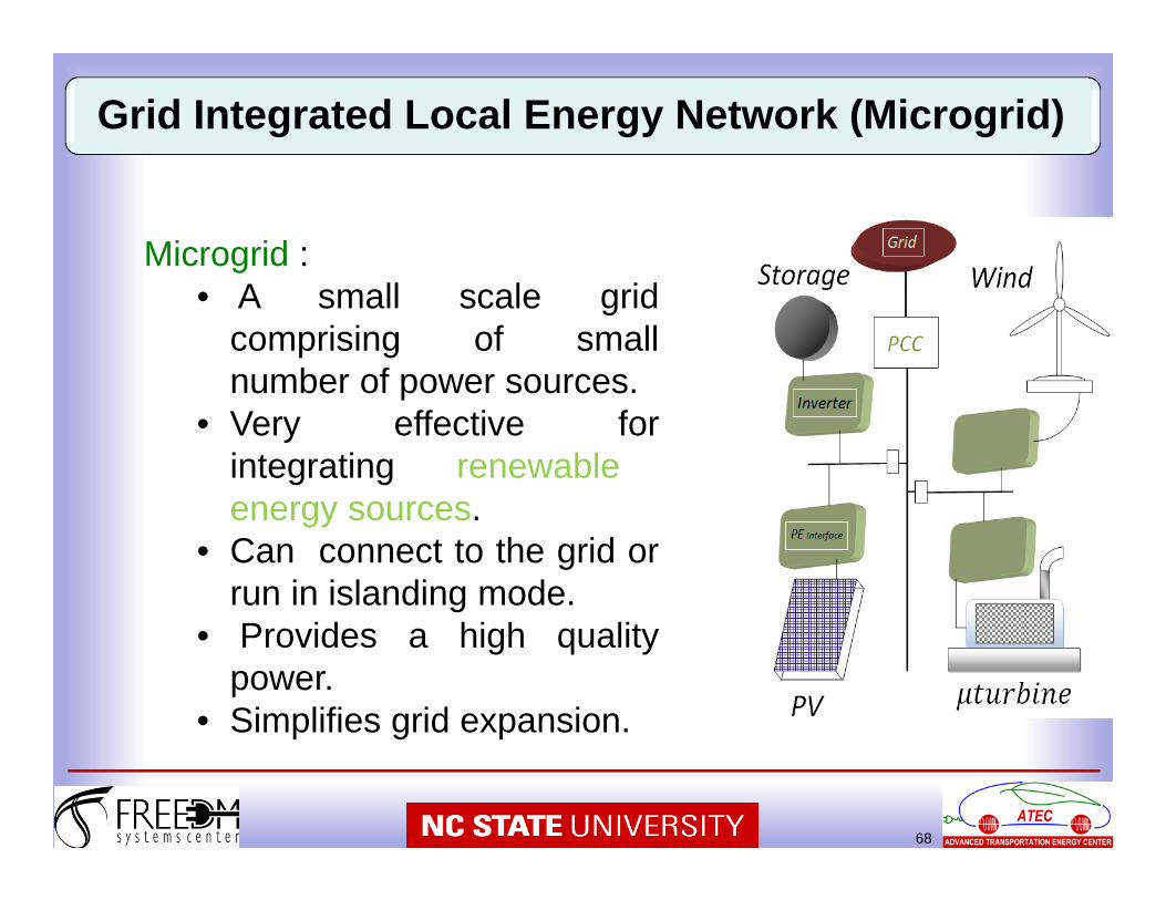
Grid Integrated Local Energy Network (Microgrid)
Microgrid :• A small scale grid
comprising of smallnumber of power sources.
• Very effective forintegrating renewableenergy sources.
• Can connect to the grid orrun in islanding mode.
• Provides a high qualitypower.
• Simplifies grid expansion.
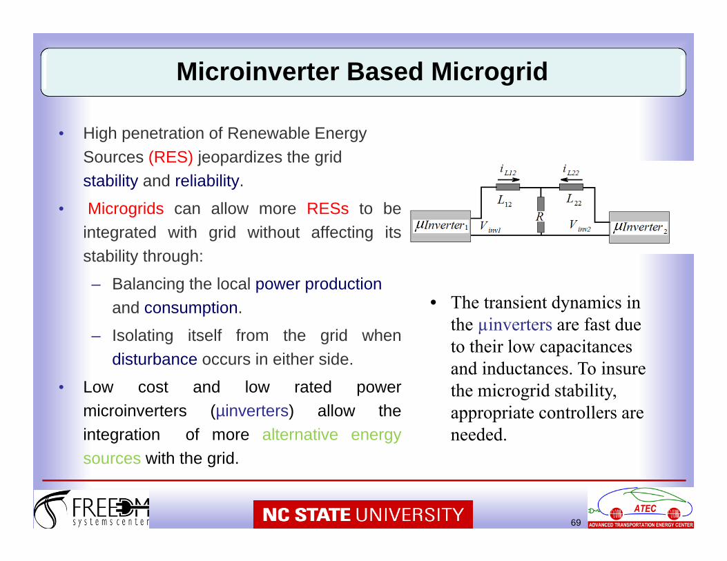
• High penetration of Renewable Energy Sources (RES) jeopardizes the grid stability and reliability.
• Microgrids can allow more RESs to beintegrated with grid without affecting itsstability through:
– Balancing the local power production and consumption.
– Isolating itself from the grid whendisturbance occurs in either side.
• Low cost and low rated powermicroinverters (µinverters) allow theintegration of more alternative energysources with the grid.
69
Microinverter Based Microgrid
• The transient dynamics in the µinverters are fast due to their low capacitances and inductances. To insure the microgrid stability, appropriate controllers are needed.
• Wind Systems have a lot of potentials, but there are also a number of challenges
• Systems level perspective is essential in all projects
• Theoretical analysis based on the fundamentals leading to modeling
• Analytical models to be verified or complemented with computational tools
• Experimental verification desired when feasible
Conclusions


![Wind Farm Electrical Systems.pptx [Read-Only]ewh.ieee.org/r3/atlanta/ias/Wind Farm Electrical Systems.pdf · 2010. 1. 19. · Wind Farm Electrical Systems. ... Maintenance Hoist](https://img.pdfslide.us/doc/110x75/6122e4b36403441c092ee882/wind-farm-electrical-read-onlyewhieeeorgr3atlantaiaswind-farm-electrical.jpg)