Embed Size (px)
Citation preview
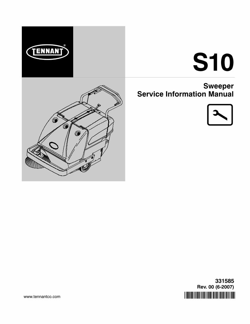
S10
*331585*www.tennantco.com
331585Rev. 00 (6-2007)
SweeperService Information Manual
S10 331585 (6--07)ii
A B
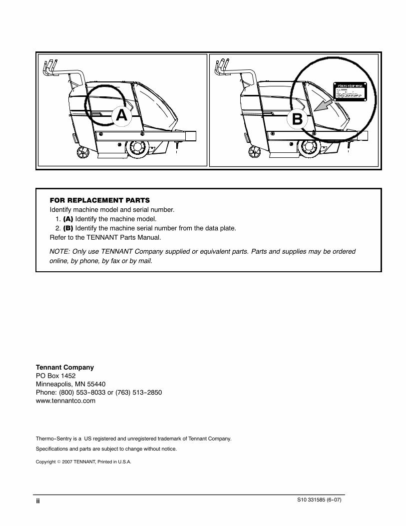
FOR REPLACEMENT PARTSIdentify machine model and serial number.1. (A) Identify the machine model.2. (B) Identify the machine serial number from the data plate.
Refer to the TENNANT Parts Manual.
NOTE: Only use TENNANT Company supplied or equivalent parts. Parts and supplies may be orderedonline, by phone, by fax or by mail.
Tennant CompanyPO Box 1452Minneapolis, MN 55440Phone: (800) 553--8033 or (763) 513--2850www.tennantco.com
Thermo--Sentry is a US registered and unregistered trademark of Tennant Company.
Specifications and parts are subject to change without notice.
Copyright E 2007 TENNANT, Printed in U.S.A.
S10 SERVICE INFORMATION Table of Contents
iiiS10 331585 (6--07)
SAFETY PRECAUTIONS v. . . . . . . . . . . . . . . . . . . . . . . . . . . . . . . . . . . .
GENERAL MACHINE INFORMATION 1. . . . . . . . . . . . . . . . . . . . . . . . .GENERAL MACHINE DIMENSIONS/CAPACITIES 2. . . . . . . . . .GENERAL MACHINE PERFORMANCE 2. . . . . . . . . . . . . . . . . . . .POWER TYPE 2. . . . . . . . . . . . . . . . . . . . . . . . . . . . . . . . . . . . . . . . . .TIRES 3. . . . . . . . . . . . . . . . . . . . . . . . . . . . . . . . . . . . . . . . . . . . . . . . .MACHINE DIMENSIONS 3. . . . . . . . . . . . . . . . . . . . . . . . . . . . . . . . .
MAINTENANCE & REPAIR 5. . . . . . . . . . . . . . . . . . . . . . . . . . . . . . . . . .MAINTENANCE CHART 6. . . . . . . . . . . . . . . . . . . . . . . . . . . . . . . . .LUBRICATION 8. . . . . . . . . . . . . . . . . . . . . . . . . . . . . . . . . . . . . . . . . .
DRIVE CHAINS 8. . . . . . . . . . . . . . . . . . . . . . . . . . . . . . . . . . . . . .DIFFERENTIAL 8. . . . . . . . . . . . . . . . . . . . . . . . . . . . . . . . . . . . . .BRUSH ARM PIVOTS 8. . . . . . . . . . . . . . . . . . . . . . . . . . . . . . . .REAR CASTER 8. . . . . . . . . . . . . . . . . . . . . . . . . . . . . . . . . . . . . .SIDE BRUSH GEAR BOX 9. . . . . . . . . . . . . . . . . . . . . . . . . . . . .SELF ADJUSTING SHEAVE 9. . . . . . . . . . . . . . . . . . . . . . . . . .
BATTERIES 10. . . . . . . . . . . . . . . . . . . . . . . . . . . . . . . . . . . . . . . . . . . .LEAD ACID BATTERIES 10. . . . . . . . . . . . . . . . . . . . . . . . . . . . . .CHARGING BATTERIES 11. . . . . . . . . . . . . . . . . . . . . . . . . . . . . .ELECTRIC MOTORS 13. . . . . . . . . . . . . . . . . . . . . . . . . . . . . . . . .BELTS AND CHAINS 13. . . . . . . . . . . . . . . . . . . . . . . . . . . . . . . . .
PROPELLING BELTS 13. . . . . . . . . . . . . . . . . . . . . . . . . . . . . . . . . . . .CHECKING/ADJUSTING BELT TENSION 13. . . . . . . . . . . . . .REPLACE PROPELLING BELTS 15. . . . . . . . . . . . . . . . . . . . . .
SIDE BRUSH BELT 15. . . . . . . . . . . . . . . . . . . . . . . . . . . . . . . . . . . . . .CHECKING/ADJUSTING BELT TENSION 15. . . . . . . . . . . . . .REPLACE SIDE BRUSH BELT 16. . . . . . . . . . . . . . . . . . . . . . . .
MAIN BRUSH BELTS 17. . . . . . . . . . . . . . . . . . . . . . . . . . . . . . . . . . . .REPLACE SHORT MAIN BRUSH BELT 17. . . . . . . . . . . . . . . .REPLACE LONG MAIN BRUSH BELT 17. . . . . . . . . . . . . . . . . .
VACUUM FAN BELT 18. . . . . . . . . . . . . . . . . . . . . . . . . . . . . . . . . . . . .CHECK/ADJUST BELT TENSION 18. . . . . . . . . . . . . . . . . . . . . .REPLACE VACUUM FAN BELT 18. . . . . . . . . . . . . . . . . . . . . . . .
WHEEL DRIVE CHAINS 19. . . . . . . . . . . . . . . . . . . . . . . . . . . . . . . . .STATIC DRAG CHAIN 19. . . . . . . . . . . . . . . . . . . . . . . . . . . . . . . . . . .BRUSHES 20. . . . . . . . . . . . . . . . . . . . . . . . . . . . . . . . . . . . . . . . . . . . . .
MAIN BRUSH 20. . . . . . . . . . . . . . . . . . . . . . . . . . . . . . . . . . . . . . .REMOVING THE MAIN BRUSH 20. . . . . . . . . . . . . . . . . . . . . . .INSTALLING THE MAIN BRUSH 20. . . . . . . . . . . . . . . . . . . . . . .CHECKING/ADJUSTING MAIN BRUSH PATTERN 20. . . . . . .SIDE BRUSH 21. . . . . . . . . . . . . . . . . . . . . . . . . . . . . . . . . . . . . . . .REMOVING THE SIDE BRUSH 21. . . . . . . . . . . . . . . . . . . . . . . .INSTALLING THE SIDE BRUSH 22. . . . . . . . . . . . . . . . . . . . . . .ADJUSTING THE SIDE BRUSH 22. . . . . . . . . . . . . . . . . . . . . . .
DEBRIS HOPPER AND DUST FILTER 22. . . . . . . . . . . . . . . . . . . . .DEBRIS HOPPER 22. . . . . . . . . . . . . . . . . . . . . . . . . . . . . . . . . . .CHECKING/ADJUSTING FLOOR CLEARANCE 22. . . . . . . . .ADJUSTING DUST FILTER TO HOPPER SEALING 23. . . . . .
THERMO-SENTRY 23. . . . . . . . . . . . . . . . . . . . . . . . . . . . . . . . . . . . . .
Table of Contents S10 SERVICE INFORMATION
S10 331585 (6--07)iv
DUST FILTER 23. . . . . . . . . . . . . . . . . . . . . . . . . . . . . . . . . . . . . . . . . . . . . . . . . . . . . .REMOVING THE DUST FILTER 24. . . . . . . . . . . . . . . . . . . . . . . . . . . . . . . . . .INSTALLING THE DUST FILTER 24. . . . . . . . . . . . . . . . . . . . . . . . . . . . . . . . .
SKIRTS AND SEALS 24. . . . . . . . . . . . . . . . . . . . . . . . . . . . . . . . . . . . . . . . . . . . . . .HOPPER LIP SKIRT 24. . . . . . . . . . . . . . . . . . . . . . . . . . . . . . . . . . . . . . . . . . . .REAR BRUSH SKIRTS 24. . . . . . . . . . . . . . . . . . . . . . . . . . . . . . . . . . . . . . . . . .HOPPER TOP SEAL 25. . . . . . . . . . . . . . . . . . . . . . . . . . . . . . . . . . . . . . . . . . . .MAIN BRUSH SKIRTS AND SEALS 25. . . . . . . . . . . . . . . . . . . . . . . . . . . . . . .
PROPEL HANDLE ASSEMBLY 26. . . . . . . . . . . . . . . . . . . . . . . . . . . . . . . . . . . . . .ADJUST PROPEL HANDLE ASSEMBLY HEIGHT 26. . . . . . . . . . . . . . . . . .
TRANSPORTING THE MACHINE 27. . . . . . . . . . . . . . . . . . . . . . . . . . . . . . . . . . . .STORING MACHINE 27. . . . . . . . . . . . . . . . . . . . . . . . . . . . . . . . . . . . . . . . . . . . . . .
ELECTRICAL TROUBLESHOOTING INFORMATION 29. . . . . . . . . . . . . . . . . . . . . .ELECTRICAL SYMBOLS & ABBREVIATIONS 30. . . . . . . . . . . . . . . . . . . . . . . . .ELECTRICAL SCHEMATIC 31. . . . . . . . . . . . . . . . . . . . . . . . . . . . . . . . . . . . . . . . . .WIRE HARNESS DRAWING 32. . . . . . . . . . . . . . . . . . . . . . . . . . . . . . . . . . . . . . . . .KEY OFF POWER DISTRIBUTION 33. . . . . . . . . . . . . . . . . . . . . . . . . . . . . . . . . . .KEY OFF POWER DISTRIBUTION (CHARGING) 34. . . . . . . . . . . . . . . . . . . . . .KEY ON POWER DISTRIBUTION 35. . . . . . . . . . . . . . . . . . . . . . . . . . . . . . . . . . . .FILTER SHAKER CIRCUIT 36. . . . . . . . . . . . . . . . . . . . . . . . . . . . . . . . . . . . . . . . . .FILTER SHAKER SYSTEM ON 37. . . . . . . . . . . . . . . . . . . . . . . . . . . . . . . . . . . . . .
S10 SERVICE INFORMATION Safety Information
vS10 331585 (6--07)
SAFETY PRECAUTIONS
The following symbols are used throughout thismanual as indicated in their description:
WARNING: To warn of hazards or unsafepractices that could result in severepersonal injury or death.
FOR SAFETY: To identify actions that mustbe followed for safe operation ofequipment.
This machine is designed solely for sweeping dirt anddust in an indoor environment. Tennant does notrecommend using this machine in any otherenvironment.
The following information signals potentiallydangerous conditions to the operator or equipment.Read this manual carefully. Know when theseconditions can exist. Locate all safety devices on themachine. Then, take necessary steps to trainmachine operating personnel. Report machinedamage or faulty operation immediately. Do not usethe machine if it is not in proper operating condition.
WARNING: Batteries emit hydrogen gas.Explosion or fire can result. Keep sparksand open flame away. Keep covers openwhen charging.
WARNING: Disconnect battery cables andcharger plug before servicing machine. Donot charge batteries with damaged powersupply cord. Do not modify plug.
If the charger supply cord is damaged or broken,it must be replaced by the manufacturer or itsservice agent or a similarly qualified person inorder to avoid a hazard.
WARNING: Heavy hopper. Do not removewithout help. Can cause back strain.
This machine is not equipped with explosionproof motors. The electric motors will spark uponstart up and during operation which could causea flash fire or explosion if machine is used in anarea where flammable vapors/liquids orcombustible dusts are present.
FOR SAFETY:
1. Do Not Operate Machine:-- Unless Trained And Authorized.-- Unless Operation Manual Is Read AndUnderstood.
-- In Flammable Or Explosive Areas UnlessDesigned For Use In Those Areas.
2. Before Starting Machine:-- Make Sure All Safety Devices Are In PlaceAnd Operate Properly.
3. When Using Machine:-- Go Slow On Grades And SlipperySurfaces.
-- Use Care When Backing Machine.
4. Before Leaving Or Servicing Machine:-- Stop On Level Surface.-- Set Parking Brake.-- Turn Off Machine And Remove Key.
5. When Servicing Machine:-- Avoid Moving Parts. Do Not Wear LooseJackets, Shirts, Or Sleeves When WorkingOn Machine.
-- Use Hoist Or Jack Of Adequate CapacityTo Lift Machine.
-- Wear Eye And Ear Protection When UsingPressurized Air Or Water.
-- Disconnect Battery Connections BeforeWorking On Machine.
-- Avoid Contact With Battery Acid.-- Use TENNANT Supplied Or EquivalentReplacement Parts.
6. When loading/unloading machine onto/offtruck or trailer.-- Turn off machine.-- Use truck or trailer that will support theweight of the machine.
-- Use winch. Do not push the machineonto/off the truck or trailer unless the loadheight is 380 mm (15 in) or less from theground.
-- Block machine tires.-- Tie machine down to truck or trailer.
S10 SERVICE INFORMATIONSafety Information
S10 331585 (6--07)vi
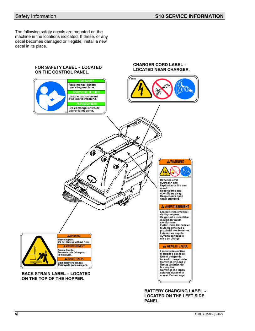
The following safety decals are mounted on themachine in the locations indicated. If these, or anydecal becomes damaged or illegible, install a newdecal in its place.
FOR SAFETY LABEL -- LOCATEDON THE CONTROL PANEL.
BATTERY CHARGING LABEL --LOCATED ON THE LEFT SIDEPANEL.
BACK STRAIN LABEL -- LOCATEDON THE TOP OF THE HOPPER.
CHARGER CORD LABEL --LOCATED NEAR CHARGER.
S10 SERVICE INFORMATION General Machine Information
1S10 331585 (6--07)
GENERAL
MACHINE
INFORMATION
BEFORE CONDUCTING TESTS:
* Read and Follow ALL Safety Warnings and Precautions as mentionedat the beginning of this manual* Always unhook Battery when removing or replacing components
DURING TESTS:
* Call Technical Services if Diagnostic Time Exceeds One Hour WithUnknown Cause or Course of Action
NOTE: Troubleshooting charts may be shown with optional equipment. The optional equipmentmay not be specified in these charts. Some machines may not be equipped with all componentsshown.
S10 SERVICE INFORMATIONGeneral Machine Information
S10 331585 (6--07)2
SPECIFICATIONS
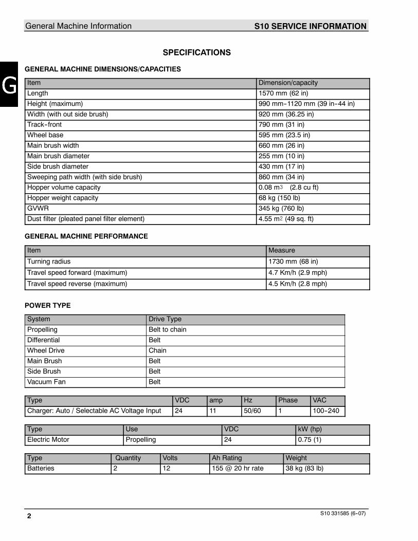
GENERAL MACHINE DIMENSIONS/CAPACITIES
Item Dimension/capacity
Length 1570 mm (62 in)
Height (maximum) 990 mm--1120 mm (39 in--44 in)
Width (with out side brush) 920 mm (36.25 in)
Track--front 790 mm (31 in)
Wheel base 595 mm (23.5 in)
Main brush width 660 mm (26 in)
Main brush diameter 255 mm (10 in)
Side brush diameter 430 mm (17 in)
Sweeping path width (with side brush) 860 mm (34 in)
Hopper volume capacity 0.08 m# (2.8 cu ft)
Hopper weight capacity 68 kg (150 lb)
GVWR 345 kg (760 lb)
Dust filter (pleated panel filter element) 4.55 m@ (49 sq. ft)
GENERAL MACHINE PERFORMANCE
Item Measure
Turning radius 1730 mm (68 in)
Travel speed forward (maximum) 4.7 Km/h (2.9 mph)
Travel speed reverse (maximum) 4.5 Km/h (2.8 mph)
POWER TYPE
System Drive Type
Propelling Belt to chain
Differential Belt
Wheel Drive Chain
Main Brush Belt
Side Brush Belt
Vacuum Fan Belt
Type VDC amp Hz Phase VAC
Charger: Auto / Selectable AC Voltage Input 24 11 50/60 1 100--240
Type Use VDC kW (hp)
Electric Motor Propelling 24 0.75 (1)
Type Quantity Volts Ah Rating Weight
Batteries 2 12 155 @ 20 hr rate 38 kg (83 lb)

S10 SERVICE INFORMATION General Machine Information
3S10 331585 (6--07)
TIRES
Location Type Size
Front (2) Solid 250 mm x 51 mm (10 in x 2 in)
Rear (1) Solid 130 mm x 38 mm (5 in x 1.5 in)
MACHINE DIMENSIONS
920 mm(36.25 in)
1570 mm(62 in)
990 mm--1120 mm(39 in--44 in)
03131

S10 SERVICE INFORMATIONGeneral Machine Information
S10 331585 (6--07)4
S10 SERVICE INFORMATION Maintenance & Repair
S10 331585 (6--07) 5
MAINTENANCE
& REPAIR
BEFORE CONDUCTING TESTS:
* Read and Follow ALL Safety Warnings and Precautions as mentionedat the beginning of this manual* Always unhook Battery when removing or replacing components
DURING TESTS:
* Call Technical Services if Diagnostic Time Exceeds One Hour WithUnknown Cause or Course of Action
NOTE: Troubleshooting charts may be shown with optional equipment. The optional equipmentmay not be specified in these charts. Some machines may not be equipped with all componentsshown.
S10 SERVICE INFORMATIONMaintenance & Repair
S10 331585 (6--07)6
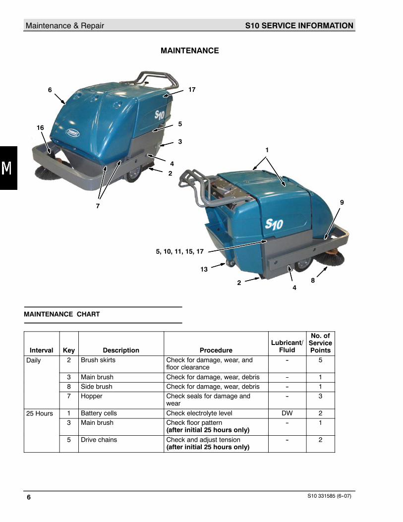
MAINTENANCE
1
2
3
4
7
8
9
13
16
2
5, 10, 11, 15, 17
5
4
6 17
MAINTENANCE CHART
Interval Key Description ProcedureLubricant/
Fluid
No. ofServicePoints
Daily 2 Brush skirts Check for damage, wear, andfloor clearance
-- 5
3 Main brush Check for damage, wear, debris -- 18 Side brush Check for damage, wear, debris -- 17 Hopper Check seals for damage and
wear-- 3
25 Hours 1 Battery cells Check electrolyte level DW 23 Main brush Check floor pattern
(after initial 25 hours only)-- 1
5 Drive chains Check and adjust tension(after initial 25 hours only)
-- 2
S10 SERVICE INFORMATION Maintenance & Repair
S10 331585 (6--07) 7
50 Hours 14 Vacuum fan belt Check tension and wear -- 110 Propelling belts Check tension and wear -- 210 Main brush belts Check tension and wear -- 29 Side brush belts Check tension and wear -- 28 Side brush Check pressure -- 13 Main brush Check floor pattern
Rotate end--for--end-- 1
4 Brush arm pivots Lubricate SPL 213 Rear caster Lubricate SPL 17 Hopper Check floor clearance -- 117 Battery charger cable Check for wear and damage -- 1
100 Hours 5 Drive chains Check and adjust tension -- 2Lubricate SO 2
6 Dust filter Clean or replace -- 111 Self adjusting sheave Lubricate SPL 11 Batteries Clean top surface and terminals -- 217 Differential Lubricate SPL 1
400 Hours 15 Propelling motor Blow out dust and inspect -- 116 Side brush gear box Check lubricant level GL 1
LUBRICANT/FLUID
DW -- Distilled waterSPL -- Special lubricant, Lubriplate EMB grease, TENNANT Part No. 01433--1SO -- Spray lubricantGL -- SAE 90 Weight gear lubricant
NOTE: More frequent intervals may be required in extremely dusty conditions.
S10 SERVICE INFORMATIONMaintenance & Repair
S10 331585 (6--07)8
LUBRICATION
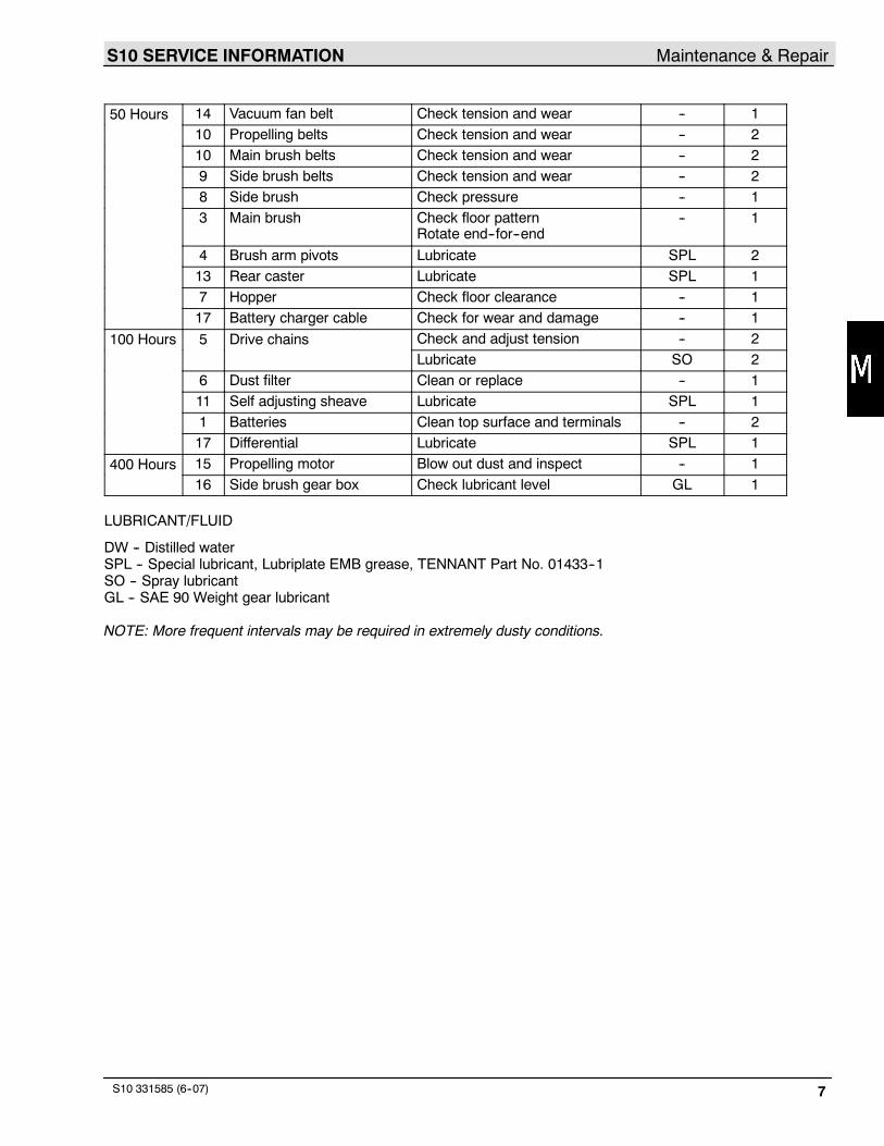
DRIVE CHAINS
Check the tension and lubricate the drive chains (A)with a penetrating-type spray lubricant after every 100hours of operation.
A
B
03139
A. Drive ChainB. Differential
DIFFERENTIAL
Lubricate the differential (B) every 100 hours ofoperation. The differential grease fitting is located onthe drive shaft inside the drive sheave.
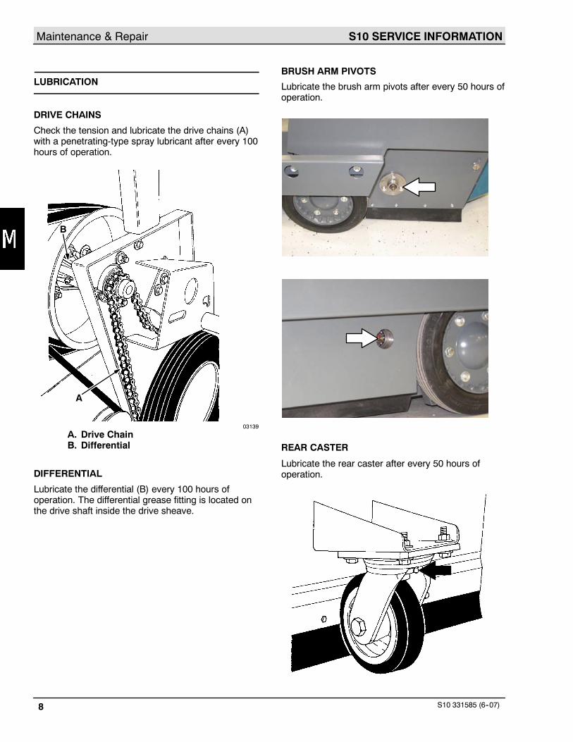
BRUSH ARM PIVOTS
Lubricate the brush arm pivots after every 50 hours ofoperation.
REAR CASTER
Lubricate the rear caster after every 50 hours ofoperation.
S10 SERVICE INFORMATION Maintenance & Repair
S10 331585 (6--07) 9
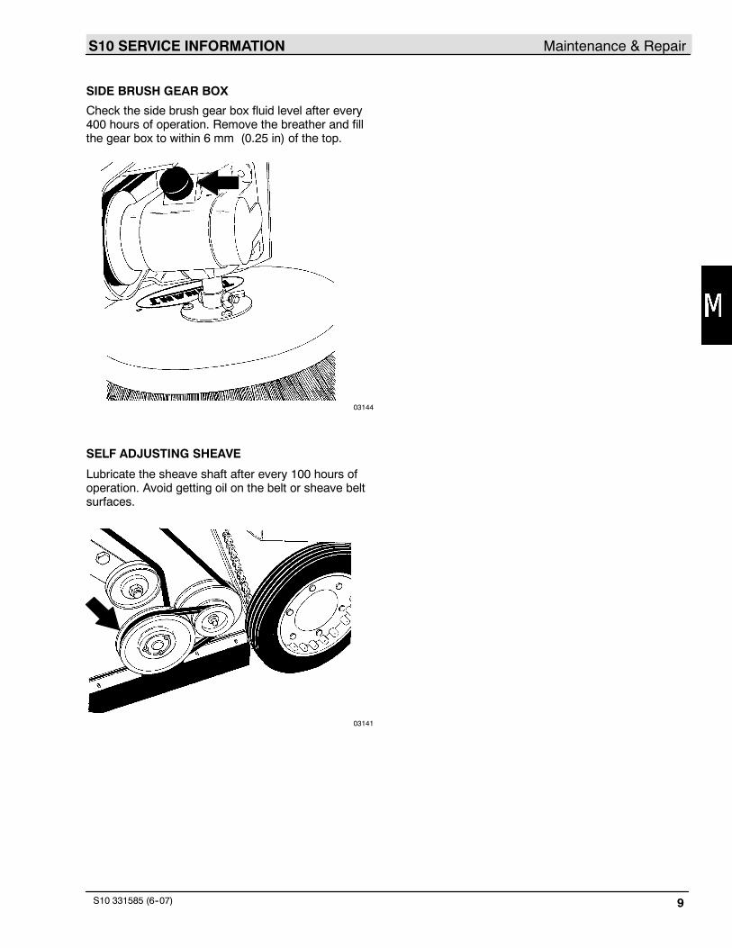
SIDE BRUSH GEAR BOX
Check the side brush gear box fluid level after every400 hours of operation. Remove the breather and fillthe gear box to within 6 mm (0.25 in) of the top.
03144
SELF ADJUSTING SHEAVE
Lubricate the sheave shaft after every 100 hours ofoperation. Avoid getting oil on the belt or sheave beltsurfaces.
03141
S10 SERVICE INFORMATIONMaintenance & Repair
S10 331585 (6--07)10
BATTERIES
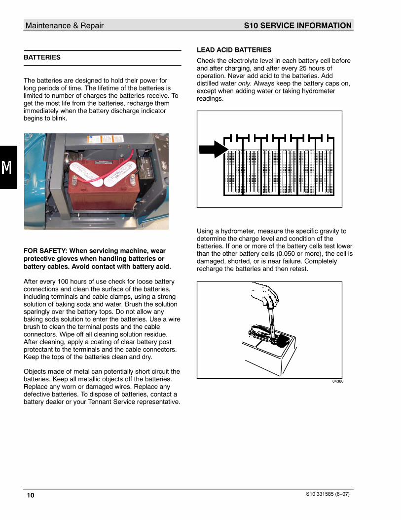
The batteries are designed to hold their power forlong periods of time. The lifetime of the batteries islimited to number of charges the batteries receive. Toget the most life from the batteries, recharge themimmediately when the battery discharge indicatorbegins to blink.
FOR SAFETY: When servicing machine, wearprotective gloves when handling batteries orbattery cables. Avoid contact with battery acid.
After every 100 hours of use check for loose batteryconnections and clean the surface of the batteries,including terminals and cable clamps, using a strongsolution of baking soda and water. Brush the solutionsparingly over the battery tops. Do not allow anybaking soda solution to enter the batteries. Use a wirebrush to clean the terminal posts and the cableconnectors. Wipe off all cleaning solution residue.After cleaning, apply a coating of clear battery postprotectant to the terminals and the cable connectors.Keep the tops of the batteries clean and dry.
Objects made of metal can potentially short circuit thebatteries. Keep all metallic objects off the batteries.Replace any worn or damaged wires. Replace anydefective batteries. To dispose of batteries, contact abattery dealer or your Tennant Service representative.
LEAD ACID BATTERIES
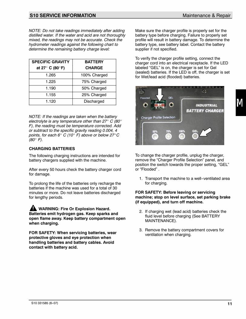
Check the electrolyte level in each battery cell beforeand after charging, and after every 25 hours ofoperation. Never add acid to the batteries. Adddistilled water only. Always keep the battery caps on,except when adding water or taking hydrometerreadings.
Using a hydrometer, measure the specific gravity todetermine the charge level and condition of thebatteries. If one or more of the battery cells test lowerthan the other battery cells (0.050 or more), the cell isdamaged, shorted, or is near failure. Completelyrecharge the batteries and then retest.
04380
S10 SERVICE INFORMATION Maintenance & Repair
S10 331585 (6--07) 11
NOTE: Do not take readings immediately after addingdistilled water. If the water and acid are not thoroughlymixed, the readings may not be accurate. Check thehydrometer readings against the following chart todetermine the remaining battery charge level:
SPECIFIC GRAVITY BATTERYat 27_ C (80_F) CHARGE
1.265 100% Charged
1.225 75% Charged
1.190 50% Charged
1.155 25% Charged
1.120 Discharged
NOTE: If the readings are taken when the batteryelectrolyte is any temperature other than 27_ C (80_F), the reading must be temperature corrected. Addor subtract to the specific gravity reading 0.004, 4points, for each 6_ C (10_ F) above or below 27_C(80_ F).
CHARGING BATTERIES
The following charging instructions are intended forbattery chargers supplied with the machine.
After every 50 hours check the battery charger cordfor damage.
To prolong the life of the batteries only recharge thebatteries if the machine was used for a total of 30minutes or more. Do not leave batteries dischargedfor lengthy periods.
WARNING: Fire Or Explosion Hazard.Batteries emit hydrogen gas. Keep sparks andopen flame away. Keep battery compartment openwhen charging.
FOR SAFETY: When servicing batteries, wearprotective gloves and eye protection whenhandling batteries and battery cables. Avoidcontact with battery acid.
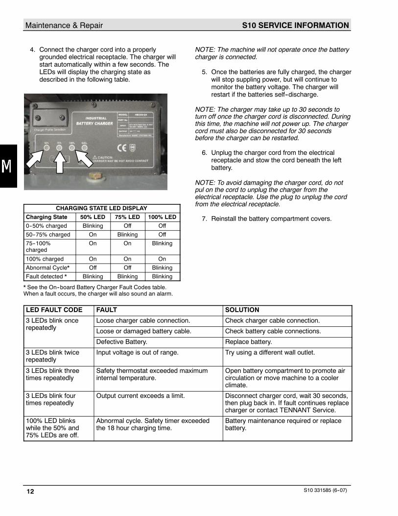
Make sure the charger profile is properly set for thebattery type before charging. Failure to properly setprofile will result in battery damage. To determine thebattery type, see battery label. Contact the batterysupplier if not specified.
To verify the charger profile setting, connect thecharger cord into an electrical receptacle. If the LEDlabeled “GEL” is on, the charger is set for Gel(sealed) batteries. If the LED is off, the charger is setfor Wet/lead acid (flooded) batteries.
To change the charger profile, unplug the charger,remove the “Charger Profile Selection” panel, andposition the switch towards the proper setting, “GEL”or “Flooded” .
1. Transport the machine to a well--ventilated areafor charging.
FOR SAFETY: Before leaving or servicingmachine; stop on level surface, set parking brake(if equipped), and turn off machine.
2. If charging wet (lead acid) batteries check thefluid level before charging (See BATTERYMAINTENANCE).
3. Remove the battery compartment covers forventilation when charging.
S10 SERVICE INFORMATIONMaintenance & Repair
S10 331585 (6--07)12
4. Connect the charger cord into a properlygrounded electrical receptacle. The charger willstart automatically within a few seconds. TheLEDs will display the charging state asdescribed in the following table.
CHARGING STATE LED DISPLAY
Charging State 50% LED 75% LED 100% LED
0--50% charged Blinking Off Off
50--75% charged On Blinking Off
75--100%charged
On On Blinking
100% charged On On On
Abnormal Cycle* Off Off Blinking
Fault detected * Blinking Blinking Blinking
* See the On--board Battery Charger Fault Codes table.When a fault occurs, the charger will also sound an alarm.
NOTE: The machine will not operate once the batterycharger is connected.
5. Once the batteries are fully charged, the chargerwill stop suppling power, but will continue tomonitor the battery voltage. The charger willrestart if the batteries self--discharge.
NOTE: The charger may take up to 30 seconds toturn off once the charger cord is disconnected. Duringthis time, the machine will not power up. The chargercord must also be disconnected for 30 secondsbefore the charger can be restarted.
6. Unplug the charger cord from the electricalreceptacle and stow the cord beneath the leftbattery.
NOTE: To avoid damaging the charger cord, do notpul on the cord to unplug the charger from theelectrical receptacle. Use the plug to unplug the cordfrom the electrical receptacle.
7. Reinstall the battery compartment covers.
LED FAULT CODE FAULT SOLUTION
3 LEDs blink oncet dl
Loose charger cable connection. Check charger cable connection.repeatedly Loose or damaged battery cable. Check battery cable connections.
Defective Battery. Replace battery.
3 LEDs blink twicerepeatedly
Input voltage is out of range. Try using a different wall outlet.
3 LEDs blink threetimes repeatedly
Safety thermostat exceeded maximuminternal temperature.
Open battery compartment to promote aircirculation or move machine to a coolerclimate.
3 LEDs blink fourtimes repeatedly
Output current exceeds a limit. Disconnect charger cord, wait 30 seconds,then plug back in. If fault continues replacecharger or contact TENNANT Service.
100% LED blinkswhile the 50% and75% LEDs are off.
Abnormal cycle. Safety timer exceededthe 18 hour charging time.
Battery maintenance required or replacebattery.
S10 SERVICE INFORMATION Maintenance & Repair
S10 331585 (6--07) 13
ELECTRIC MOTORS
The electric propelling motor is serviceable. Thepropelling motor is located underneath the batterycompartment.
Blow out the dust and inspect the motor brushes inthe motor after every 400 hours of operation.
If the brushes have been worn to less than 10 mm(0.38 in) in length, replace them.
If the commutator is worn or rough, the motorarmature should be removed and serviced, orreplaced.
BELTS AND CHAINS
PROPELLING BELTS
Check the propelling belts for wear and tension afterevery 50 hours of operation.
CHECKING AND ADJUSTING THE PROPELLINGBELT TENSION
FOR SAFETY: Before leaving or servicingmachine; stop on level surface, set parking brake(if equipped), and turn off machine.
1. Remove the access cover, bumper, and cover.
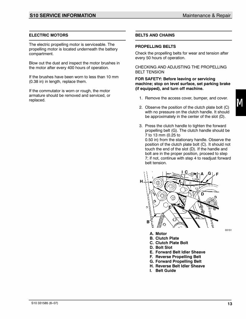
2. Observe the position of the clutch plate bolt (C)with no pressure on the clutch handle. It shouldbe approximately in the center of the slot (D).
3. Press the clutch handle to tighten the forwardpropelling belt (G). The clutch handle should be7 to 13 mm (0.25 to0.50 in) from the stationary handle. Observe theposition of the clutch plate bolt (C). It should nottouch the end of the slot (D). If the handle andbolt are in the proper position, proceed to step7; if not, continue with step 4 to readjust forwardbelt tension.
A
B
C
D
H
G F
E
I
03151
A. MotorB. Clutch PlateC. Clutch Plate BoltD. Bolt SlotE. Forward Belt Idler SheaveF. Reverse Propelling BeltG. Forward Propelling BeltH. Reverse Belt Idler SheaveI. Belt Guide

S10 SERVICE INFORMATIONMaintenance & Repair
S10 331585 (6--07)14
4. Loosen the forward idler sheave bolt (E) andslide the idler sheave down to tighten the belt(G) (this also increases distance between clutchhandle and stationary handle); slide the sheaveup to loosen the belt (this also reduces distancebetween clutch handle and stationary handle).
5. Tighten the idler sheave bolt.
6. Recheck handle and bolt positions. Repeat asnecessary to adjust belt tension.
NOTE: After adjusting the forward belt, it may contactthe belt guide when engaged causing a whining noise.To stop the noise, bend the guide up out of the belt’sway.
7. Pull the clutch handle to tighten the reversepropelling belt. Observe the position of theclutch plate bolt (C). It should not touch the endof the slot (D). If the bolt is in the properposition, proceed to step 11; if not, continue withstep 8 to readjust reverse belt tension.
NOTE: If the reverse belt is too tight, it will requireexcessive clutch handle pressure to propel machinein the forward direction. It may also cause themachine to creep backward when the handle isreleased. If the reverse belt is too loose, the machinewill not propel backward.
8. Loosen the reverse idler sheave bolt (H) andslide the idler sheave to the rear to tighten thebelt (F); slide the sheave forward to loosen thebelt.
9. Tighten the reverse idler sheave bolt (H).
10. Pull the clutch handle to recheck the position ofthe clutch plate bolt (C). Repeat as necessary toadjust belt tension.
11. Check steering effort. After repairing orreplacing drive system parts, effort mayincrease due to poor alignment. To correct, dothe following:
A. Loosen the bearing flanges as well as thesplit coupling bolts.
B. Snug one split coupling bolt.
C. Align the propelling belts. Check forclearance between the differential and thelocking collar.
NOTE: Minimum clearance between differential andsheave is 0.3 mm (0.010 in).
D. While holding belt alignment, pull the shaftaway from the differential.
E. Tighten the center and left bearing flanges.Check for hard rotation of shaft.
F. Tighten the center and left bearing collars.
G. Pull the short differential shaft away fromdifferential to spread the differential gears.
H. Tighten the right side bearing flange. Tapbearing before tightening.
I. Tighten the right bearing collar.
J. Check for free spinning of differential.Loosen the center and right bearing flangesif it is not spinning freely. Tap and retighten.
K. Align and tighten sprockets. Chains mustbe slack to minimize steering effort.
12. Reinstall the access cover, and right side cover,and bumper.
S10 SERVICE INFORMATION Maintenance & Repair
S10 331585 (6--07) 15
REPLACE PROPELLING BELTS
FOR SAFETY: Before leaving or servicingmachine; stop on level surface, set parking brake(if equipped), and turn off machine.
1. Remove the bumper and right side cover,debris hopper, and access cover.
2. Loosen the belt idler sheave bolts.
3. Slip the propelling belts off the idler sheaves.
4. Lift the filter cover.
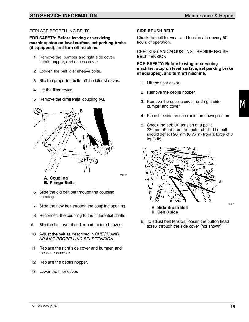
5. Remove the differential coupling (A).
A
B
03147
A. CouplingB. Flange Bolts
6. Slide the old belt out through the couplingopening.
7. Slide the new belt through the coupling opening.
8. Reconnect the coupling to the differential shafts.
9. Slip the belt over the idler and motor sheaves.
10. Adjust the belt as described in CHECK ANDADJUST PROPELLING BELT TENSION.
11. Replace the right side cover and bumper, andthe access cover.
12. Replace the debris hopper.
13. Lower the filter cover.
SIDE BRUSH BELT
Check the belt for wear and tension after every 50hours of operation.
CHECKING AND ADJUSTING THE SIDE BRUSHBELT TENSION
FOR SAFETY: Before leaving or servicingmachine; stop on level surface, set parking brake(if equipped), and turn off machine.
1. Lift the filter cover.
2. Remove the debris hopper.
3. Remove the access cover, and right sidebumper and cover.
4. Place the side brush arm in the down position.
5. Check the belt (A) tension at a point230 mm (9 in) from the motor shaft. The beltshould deflect 20 mm (0.75 in) from a force of 3kg (6 lb).
B
A
03151
A. Side Brush BeltB. Belt Guide
6. To adjust belt tension, loosen the button headscrew through the side cover (not shown).
S10 SERVICE INFORMATIONMaintenance & Repair
S10 331585 (6--07)16
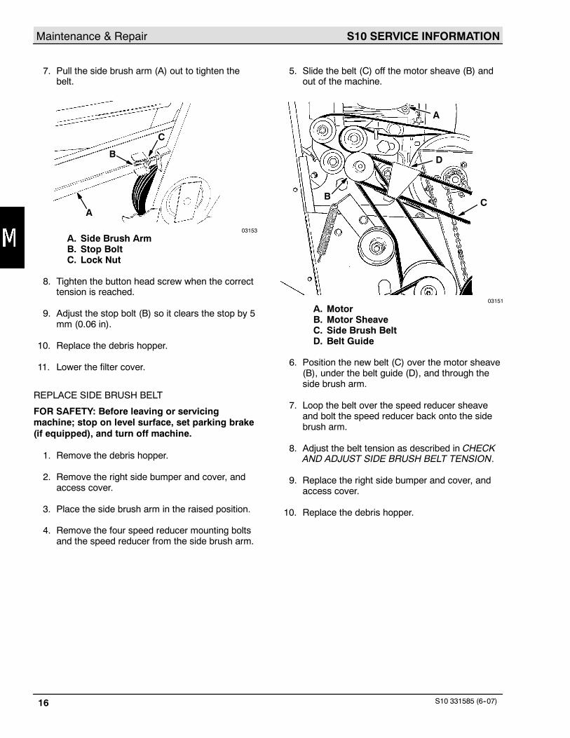
7. Pull the side brush arm (A) out to tighten thebelt.
B
A
C
03153
A. Side Brush ArmB. Stop BoltC. Lock Nut
8. Tighten the button head screw when the correcttension is reached.
9. Adjust the stop bolt (B) so it clears the stop by 5mm (0.06 in).
10. Replace the debris hopper.
11. Lower the filter cover.
REPLACE SIDE BRUSH BELT
FOR SAFETY: Before leaving or servicingmachine; stop on level surface, set parking brake(if equipped), and turn off machine.
1. Remove the debris hopper.
2. Remove the right side bumper and cover, andaccess cover.
3. Place the side brush arm in the raised position.
4. Remove the four speed reducer mounting boltsand the speed reducer from the side brush arm.
5. Slide the belt (C) off the motor sheave (B) andout of the machine.
A
D
CB
03151
A. MotorB. Motor SheaveC. Side Brush BeltD. Belt Guide
6. Position the new belt (C) over the motor sheave(B), under the belt guide (D), and through theside brush arm.
7. Loop the belt over the speed reducer sheaveand bolt the speed reducer back onto the sidebrush arm.
8. Adjust the belt tension as described in CHECKAND ADJUST SIDE BRUSH BELT TENSION.
9. Replace the right side bumper and cover, andaccess cover.
10. Replace the debris hopper.
S10 SERVICE INFORMATION Maintenance & Repair
S10 331585 (6--07) 17
MAIN BRUSH BELTS
Check the main brush belts for wear after every 50hours of operation. The short main brush belt uses aself--adjusting sheave to control belt tension and isnot adjustable. The long main brush belt uses aspring tensioned idler pulley to control belt tensionand is not adjustable.
REPLACE SHORT MAIN BRUSH BELT
FOR SAFETY: Before leaving or servicingmachine; stop on level surface, set parking brake(if equipped), and turn off machine.
1. Remove the debris hopper.
2. Remove the right side bumper and cover, andaccess cover.
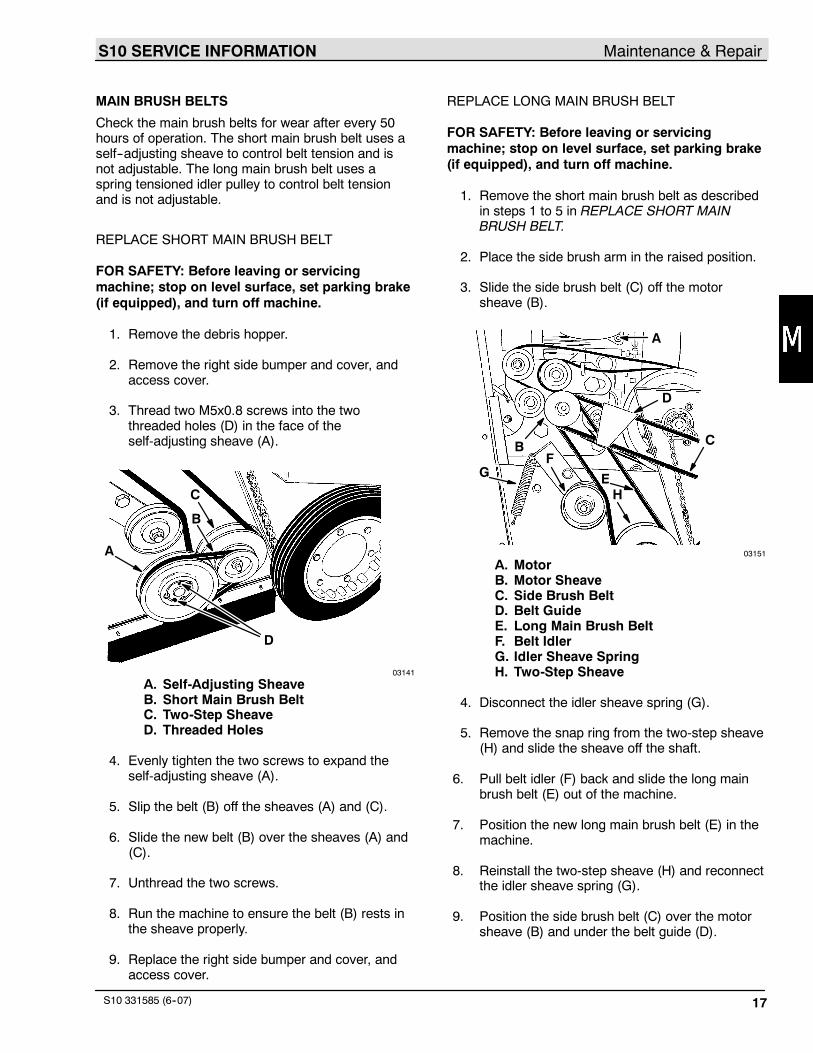
3. Thread two M5x0.8 screws into the twothreaded holes (D) in the face of theself-adjusting sheave (A).
A
B
C
D
03141
A. Self-Adjusting SheaveB. Short Main Brush BeltC. Two-Step SheaveD. Threaded Holes
4. Evenly tighten the two screws to expand theself-adjusting sheave (A).
5. Slip the belt (B) off the sheaves (A) and (C).
6. Slide the new belt (B) over the sheaves (A) and(C).
7. Unthread the two screws.
8. Run the machine to ensure the belt (B) rests inthe sheave properly.
9. Replace the right side bumper and cover, andaccess cover.
REPLACE LONG MAIN BRUSH BELT
FOR SAFETY: Before leaving or servicingmachine; stop on level surface, set parking brake(if equipped), and turn off machine.
1. Remove the short main brush belt as describedin steps 1 to 5 in REPLACE SHORT MAINBRUSH BELT.
2. Place the side brush arm in the raised position.
3. Slide the side brush belt (C) off the motorsheave (B).
A
B C
D
FEG
H
03151
A. MotorB. Motor SheaveC. Side Brush BeltD. Belt GuideE. Long Main Brush BeltF. Belt IdlerG. Idler Sheave SpringH. Two-Step Sheave
4. Disconnect the idler sheave spring (G).
5. Remove the snap ring from the two-step sheave(H) and slide the sheave off the shaft.
6. Pull belt idler (F) back and slide the long mainbrush belt (E) out of the machine.
7. Position the new long main brush belt (E) in themachine.
8. Reinstall the two-step sheave (H) and reconnectthe idler sheave spring (G).
9. Position the side brush belt (C) over the motorsheave (B) and under the belt guide (D).
S10 SERVICE INFORMATIONMaintenance & Repair
S10 331585 (6--07)18
10. Slide the short main brush belt over theself-adjusting sheave and the two-step sheave.
11. Unthread the two screws separating theself-adjusting sheave.
12. Run the brush to confirm the belt is seated inthe sheave.
13. Adjust the belt tension as described in CHECKAND ADJUST SIDE BRUSH BELT TENSION.
14. Replace the right side bumper and cover, andaccess cover.
15. Replace the debris hopper.
VACUUM FAN BELT
Check the vacuum fan belt for wear and tension afterevery 50 hours of operation.
CHECK AND ADJUST VACUUM FAN BELTTENSION
FOR SAFETY: Before leaving or servicingmachine; stop on level surface, set parking brake(if equipped), and turn off machine.
1. Remove the rear panel.
2. Check belt deflection by applying a force of6 lb (3 kg) to the midpoint of the belt span. Thebelt should deflect 5 mm (0.06 in).
3. To adjust belt tension, loosen the belt adjustingstud nut (C). Pull the vacuum fan assembly (A)back to tighten the belt and tighten the stud nut.
A
C
B
06320
A. Vacuum FanB. Adjustment SlotC. Stud Nut
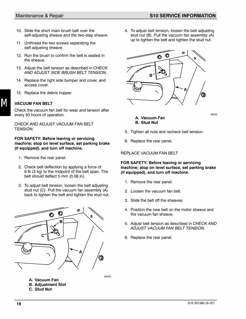
4. To adjust belt tension, loosen the belt adjustingstud nut (B). Pull the vacuum fan assembly (A)up to tighten the belt and tighten the stud nut.
A
B
06320
A. Vacuum FanB. Stud Nut
5. Tighten all nuts and recheck belt tension.
6. Replace the rear panel.
REPLACE VACUUM FAN BELT
FOR SAFETY: Before leaving or servicingmachine; stop on level surface, set parking brake(if equipped), and turn off machine.
1. Remove the rear panel.
2. Loosen the vacuum fan belt.
3. Slide the belt off the sheaves.
4. Position the new belt on the motor sheave andthe vacuum fan sheave.
5. Adjust belt tension as described in CHECK ANDADJUST VACUUM FAN BELT TENSION.
6. Replace the rear panel.
S10 SERVICE INFORMATION Maintenance & Repair
S10 331585 (6--07) 19
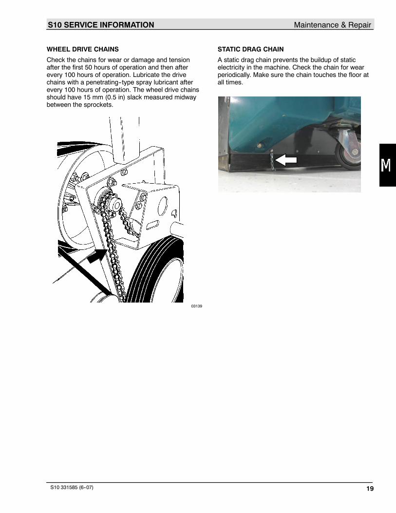
WHEEL DRIVE CHAINS
Check the chains for wear or damage and tensionafter the first 50 hours of operation and then afterevery 100 hours of operation. Lubricate the drivechains with a penetrating--type spray lubricant afterevery 100 hours of operation. The wheel drive chainsshould have 15 mm (0.5 in) slack measured midwaybetween the sprockets.
03139
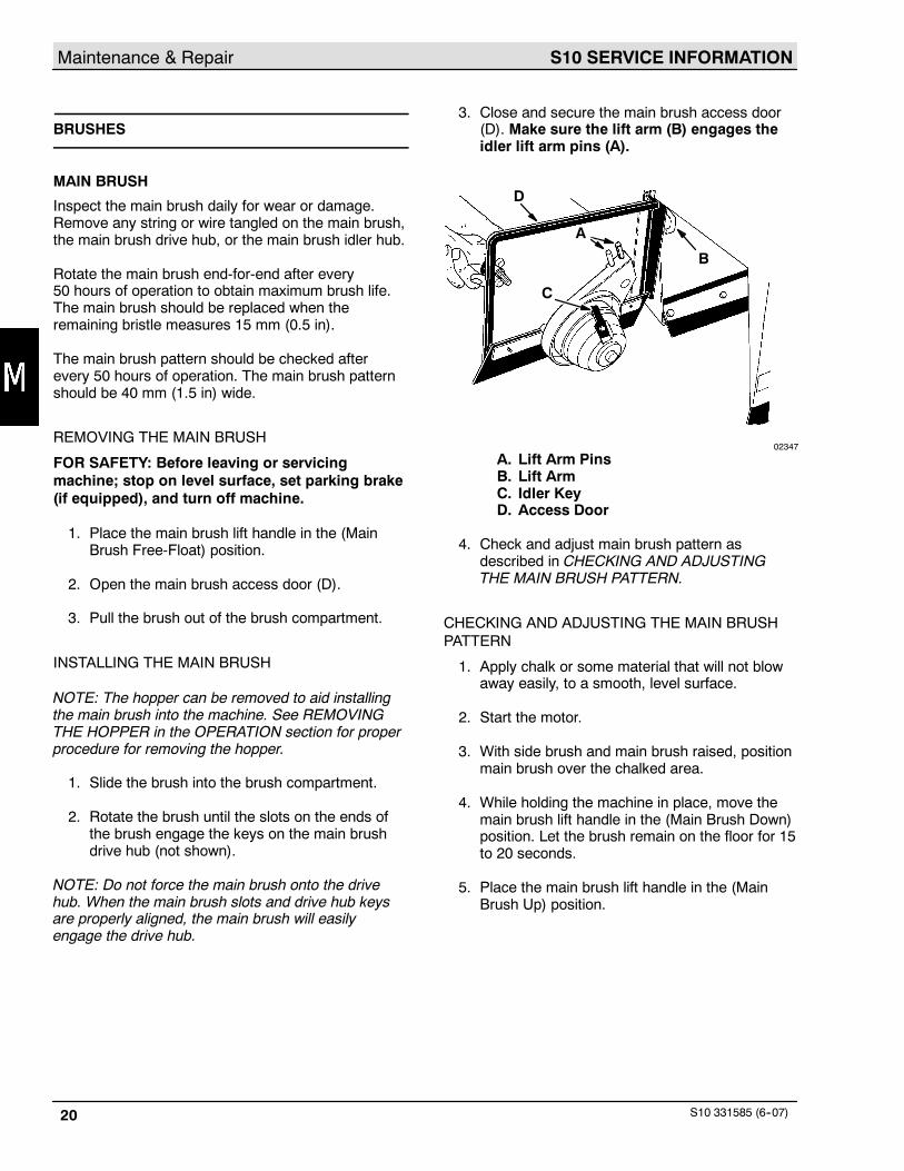
STATIC DRAG CHAIN
A static drag chain prevents the buildup of staticelectricity in the machine. Check the chain for wearperiodically. Make sure the chain touches the floor atall times.
S10 SERVICE INFORMATIONMaintenance & Repair
S10 331585 (6--07)20
BRUSHES
MAIN BRUSH
Inspect the main brush daily for wear or damage.Remove any string or wire tangled on the main brush,the main brush drive hub, or the main brush idler hub.
Rotate the main brush end-for-end after every50 hours of operation to obtain maximum brush life.The main brush should be replaced when theremaining bristle measures 15 mm (0.5 in).
The main brush pattern should be checked afterevery 50 hours of operation. The main brush patternshould be 40 mm (1.5 in) wide.
REMOVING THE MAIN BRUSH
FOR SAFETY: Before leaving or servicingmachine; stop on level surface, set parking brake(if equipped), and turn off machine.
1. Place the main brush lift handle in the (MainBrush Free-Float) position.
2. Open the main brush access door (D).
3. Pull the brush out of the brush compartment.
INSTALLING THE MAIN BRUSH
NOTE: The hopper can be removed to aid installingthe main brush into the machine. See REMOVINGTHE HOPPER in the OPERATION section for properprocedure for removing the hopper.
1. Slide the brush into the brush compartment.
2. Rotate the brush until the slots on the ends ofthe brush engage the keys on the main brushdrive hub (not shown).
NOTE: Do not force the main brush onto the drivehub. When the main brush slots and drive hub keysare properly aligned, the main brush will easilyengage the drive hub.
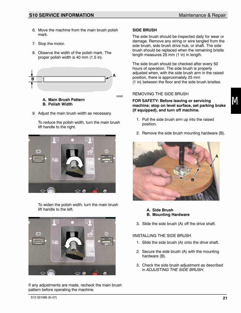
3. Close and secure the main brush access door(D). Make sure the lift arm (B) engages theidler lift arm pins (A).
D
C
A
B
02347
A. Lift Arm PinsB. Lift ArmC. Idler KeyD. Access Door
4. Check and adjust main brush pattern asdescribed in CHECKING AND ADJUSTINGTHE MAIN BRUSH PATTERN.
CHECKING AND ADJUSTING THE MAIN BRUSHPATTERN
1. Apply chalk or some material that will not blowaway easily, to a smooth, level surface.
2. Start the motor.
3. With side brush and main brush raised, positionmain brush over the chalked area.
4. While holding the machine in place, move themain brush lift handle in the (Main Brush Down)position. Let the brush remain on the floor for 15to 20 seconds.
5. Place the main brush lift handle in the (MainBrush Up) position.
S10 SERVICE INFORMATION Maintenance & Repair
S10 331585 (6--07) 21
6. Move the machine from the main brush polishmark.
7. Stop the motor.
8. Observe the width of the polish mark. Theproper polish width is 40 mm (1.5 in).
AB
00582
A. Main Brush PatternB. Polish Width
9. Adjust the main brush width as necessary.
To reduce the polish width, turn the main brushlift handle to the right.
To widen the polish width, turn the main brushlift handle to the left.
If any adjustments are made, recheck the main brushpattern before operating the machine.
SIDE BRUSH
The side brush should be inspected daily for wear ordamage. Remove any string or wire tangled from theside brush, side brush drive hub, or shaft. The sidebrush should be replaced when the remaining bristlelength measures 25 mm (1 in) in length.
The side brush should be checked after every 50hours of operation. The side brush is properlyadjusted when, with the side brush arm in the raisedposition, there is approximately 25 mm(1 in) between the floor and the side brush bristles.
REMOVING THE SIDE BRUSH
FOR SAFETY: Before leaving or servicingmachine; stop on level surface, set parking brake(if equipped), and turn off machine.
1. Pull the side brush arm up into the raisedposition.
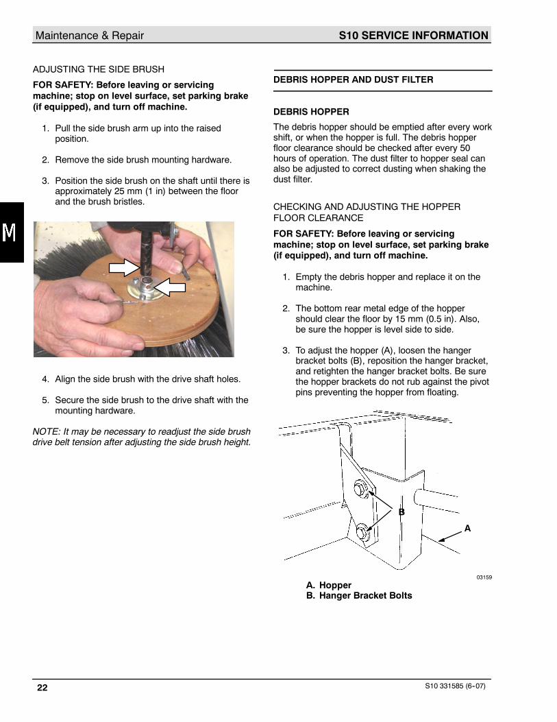
2. Remove the side brush mounting hardware (B).
A
B
A. Side BrushB. Mounting Hardware
3. Slide the side brush (A) off the drive shaft.
IINSTALLING THE SIDE BRUSH
1. Slide the side brush (A) onto the drive shaft.
2. Secure the side brush (A) with the mountinghardware (B).
3. Check the side brush adjustment as describedin ADJUSTING THE SIDE BRUSH.
S10 SERVICE INFORMATIONMaintenance & Repair
S10 331585 (6--07)22
ADJUSTING THE SIDE BRUSH
FOR SAFETY: Before leaving or servicingmachine; stop on level surface, set parking brake(if equipped), and turn off machine.
1. Pull the side brush arm up into the raisedposition.
2. Remove the side brush mounting hardware.
3. Position the side brush on the shaft until there isapproximately 25 mm (1 in) between the floorand the brush bristles.
4. Align the side brush with the drive shaft holes.
5. Secure the side brush to the drive shaft with themounting hardware.
NOTE: It may be necessary to readjust the side brushdrive belt tension after adjusting the side brush height.
DEBRIS HOPPER AND DUST FILTER
DEBRIS HOPPER
The debris hopper should be emptied after every workshift, or when the hopper is full. The debris hopperfloor clearance should be checked after every 50hours of operation. The dust filter to hopper seal canalso be adjusted to correct dusting when shaking thedust filter.
CHECKING AND ADJUSTING THE HOPPERFLOOR CLEARANCE
FOR SAFETY: Before leaving or servicingmachine; stop on level surface, set parking brake(if equipped), and turn off machine.
1. Empty the debris hopper and replace it on themachine.
2. The bottom rear metal edge of the hoppershould clear the floor by 15 mm (0.5 in). Also,be sure the hopper is level side to side.
3. To adjust the hopper (A), loosen the hangerbracket bolts (B), reposition the hanger bracket,and retighten the hanger bracket bolts. Be surethe hopper brackets do not rub against the pivotpins preventing the hopper from floating.
B
A
03159
A. HopperB. Hanger Bracket Bolts
S10 SERVICE INFORMATION Maintenance & Repair
S10 331585 (6--07) 23
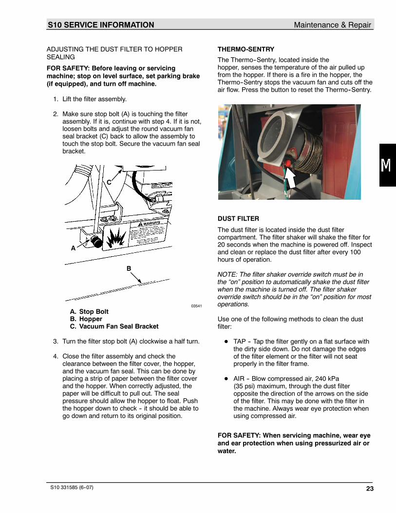
ADJUSTING THE DUST FILTER TO HOPPERSEALING
FOR SAFETY: Before leaving or servicingmachine; stop on level surface, set parking brake(if equipped), and turn off machine.
1. Lift the filter assembly.
2. Make sure stop bolt (A) is touching the filterassembly. If it is, continue with step 4. If it is not,loosen bolts and adjust the round vacuum fanseal bracket (C) back to allow the assembly totouch the stop bolt. Secure the vacuum fan sealbracket.
B
A
C
03541
A. Stop BoltB. HopperC. Vacuum Fan Seal Bracket
3. Turn the filter stop bolt (A) clockwise a half turn.
4. Close the filter assembly and check theclearance between the filter cover, the hopper,and the vacuum fan seal. This can be done byplacing a strip of paper between the filter coverand the hopper. When correctly adjusted, thepaper will be difficult to pull out. The sealpressure should allow the hopper to float. Pushthe hopper down to check -- it should be able togo down and return to its original position.
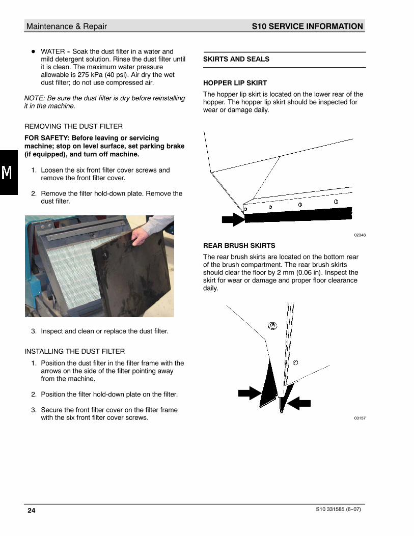
THERMO-SENTRY
The Thermo--Sentry, located inside thehopper, senses the temperature of the air pulled upfrom the hopper. If there is a fire in the hopper, theThermo--Sentry stops the vacuum fan and cuts off theair flow. Press the button to reset the Thermo--Sentry.
DUST FILTER
The dust filter is located inside the dust filtercompartment. The filter shaker will shake the filter for20 seconds when the machine is powered off. Inspectand clean or replace the dust filter after every 100hours of operation.
NOTE: The filter shaker override switch must be inthe “on” position to automatically shake the dust filterwhen the machine is turned off. The filter shakeroverride switch should be in the “on” position for mostoperations.
Use one of the following methods to clean the dustfilter:
D TAP -- Tap the filter gently on a flat surface withthe dirty side down. Do not damage the edgesof the filter element or the filter will not seatproperly in the filter frame.
D AIR -- Blow compressed air, 240 kPa(35 psi) maximum, through the dust filteropposite the direction of the arrows on the sideof the filter. This may be done with the filter inthe machine. Always wear eye protection whenusing compressed air.
FOR SAFETY: When servicing machine, wear eyeand ear protection when using pressurized air orwater.
S10 SERVICE INFORMATIONMaintenance & Repair
S10 331585 (6--07)24
D WATER -- Soak the dust filter in a water andmild detergent solution. Rinse the dust filter untilit is clean. The maximum water pressureallowable is 275 kPa (40 psi). Air dry the wetdust filter; do not use compressed air.
NOTE: Be sure the dust filter is dry before reinstallingit in the machine.
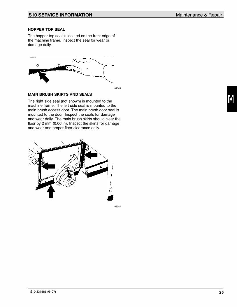
REMOVING THE DUST FILTER
FOR SAFETY: Before leaving or servicingmachine; stop on level surface, set parking brake(if equipped), and turn off machine.
1. Loosen the six front filter cover screws andremove the front filter cover.
2. Remove the filter hold-down plate. Remove thedust filter.
3. Inspect and clean or replace the dust filter.
INSTALLING THE DUST FILTER
1. Position the dust filter in the filter frame with thearrows on the side of the filter pointing awayfrom the machine.
2. Position the filter hold-down plate on the filter.
3. Secure the front filter cover on the filter framewith the six front filter cover screws.
SKIRTS AND SEALS
HOPPER LIP SKIRT
The hopper lip skirt is located on the lower rear of thehopper. The hopper lip skirt should be inspected forwear or damage daily.
02348
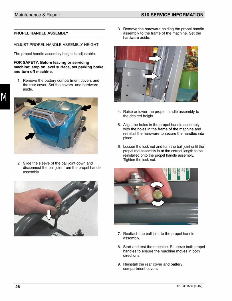
REAR BRUSH SKIRTS
The rear brush skirts are located on the bottom rearof the brush compartment. The rear brush skirtsshould clear the floor by 2 mm (0.06 in). Inspect theskirt for wear or damage and proper floor clearancedaily.
03157
S10 SERVICE INFORMATION Maintenance & Repair
S10 331585 (6--07) 25
HOPPER TOP SEAL
The hopper top seal is located on the front edge ofthe machine frame. Inspect the seal for wear ordamage daily.
02349
MAIN BRUSH SKIRTS AND SEALS
The right side seal (not shown) is mounted to themachine frame. The left side seal is mounted to themain brush access door. The main brush door seal ismounted to the door. Inspect the seals for damageand wear daily. The main brush skirts should clear thefloor by 2 mm (0.06 in). Inspect the skirts for damageand wear and proper floor clearance daily.
02347
S10 SERVICE INFORMATIONMaintenance & Repair
S10 331585 (6--07)26
PROPEL HANDLE ASSEMBLY
ADJUST PROPEL HANDLE ASSEMBLY HEIGHT
The propel handle assembly height is adjustable.
FOR SAFETY: Before leaving or servicingmachine; stop on level surface, set parking brake,and turn off machine.
1. Remove the battery compartment covers andthe rear cover. Set the covers and hardwareaside.
2. Slide the sleeve of the ball joint down anddisconnect the ball joint from the propel handleassembly.
3. Remove the hardware holding the propel handleassembly to the frame of the machine. Set thehardware aside.
4. Raise or lower the propel handle assembly tothe desired height.
5. Align the holes in the propel handle assemblywith the holes in the frame of the machine andreinstall the hardware to secure the handles intoplace.
6. Loosen the lock nut and turn the ball joint until thepropel rod assembly is at the correct length to bereinstalled onto the propel handle assembly.Tighten the lock nut.
7. Reattach the ball joint to the propel handleassembly.
8. Start and test the machine. Squeeze both propelhandles to ensure the machine moves in bothdirections.
9. Reinstall the rear cover and batterycompartment covers.
S10 SERVICE INFORMATION Maintenance & Repair
S10 331585 (6--07) 27
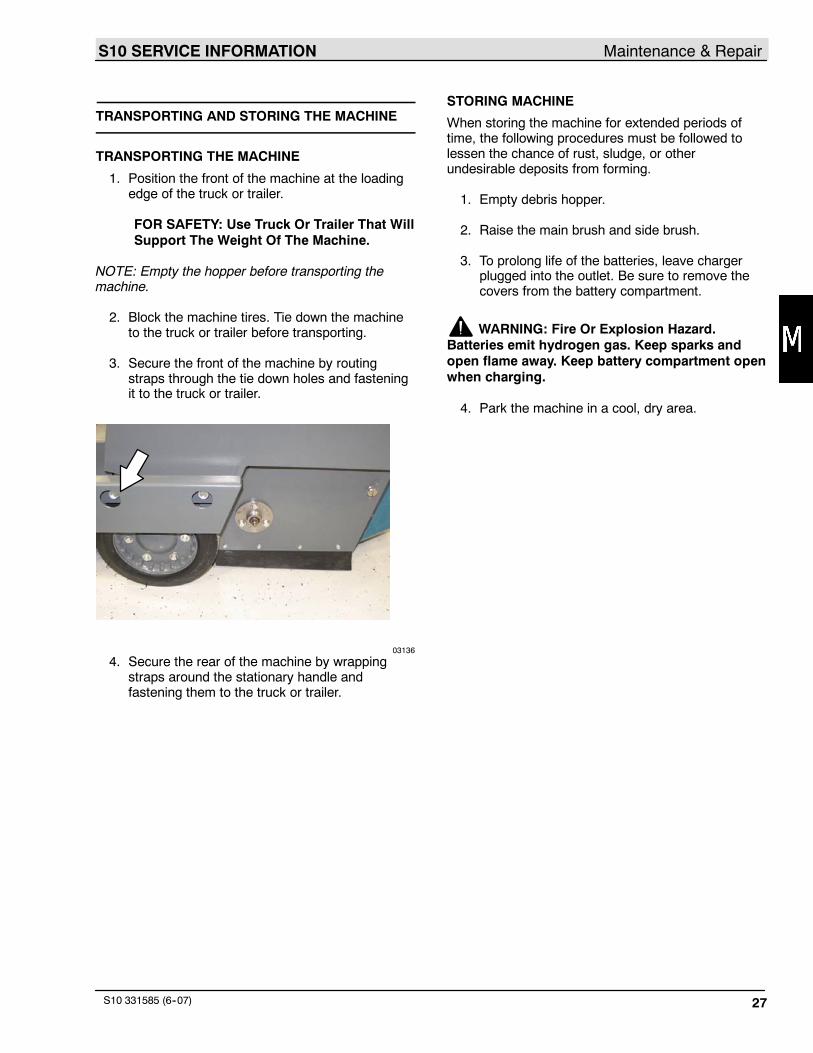
TRANSPORTING AND STORING THE MACHINE
TRANSPORTING THE MACHINE
1. Position the front of the machine at the loadingedge of the truck or trailer.
FOR SAFETY: Use Truck Or Trailer That WillSupport The Weight Of The Machine.
NOTE: Empty the hopper before transporting themachine.
2. Block the machine tires. Tie down the machineto the truck or trailer before transporting.
3. Secure the front of the machine by routingstraps through the tie down holes and fasteningit to the truck or trailer.
03136
4. Secure the rear of the machine by wrappingstraps around the stationary handle andfastening them to the truck or trailer.
STORING MACHINE
When storing the machine for extended periods oftime, the following procedures must be followed tolessen the chance of rust, sludge, or otherundesirable deposits from forming.
1. Empty debris hopper.
2. Raise the main brush and side brush.
3. To prolong life of the batteries, leave chargerplugged into the outlet. Be sure to remove thecovers from the battery compartment.
WARNING: Fire Or Explosion Hazard.Batteries emit hydrogen gas. Keep sparks andopen flame away. Keep battery compartment openwhen charging.
4. Park the machine in a cool, dry area.

S10 SERVICE INFORMATIONMaintenance & Repair
S10 331585 (6--07)28

S10 SERVICE INFORMATION Electrical Troubleshooting
S10 331585 (6--07) 29
ELECTRICAL
Troubleshooting Information
BEFORE CONDUCTING TESTS:
* Read and Follow ALL Safety Warnings and Precautions as mentionedat the beginning of this manual* Always unhook Battery when removing or replacing components
DURING TESTS:
* Call Technical Services if Diagnostic Time Exceeds One Hour WithUnknown Cause or Course of Action
NOTE: Troubleshooting charts may be shown with optional equipment. The optional equipmentmay not be specified in these charts. Some machines may not be equipped with all componentsshown.
Electrical Troubleshooting S10 SERVICE INFORMATION
S10 331585 (6--07)30
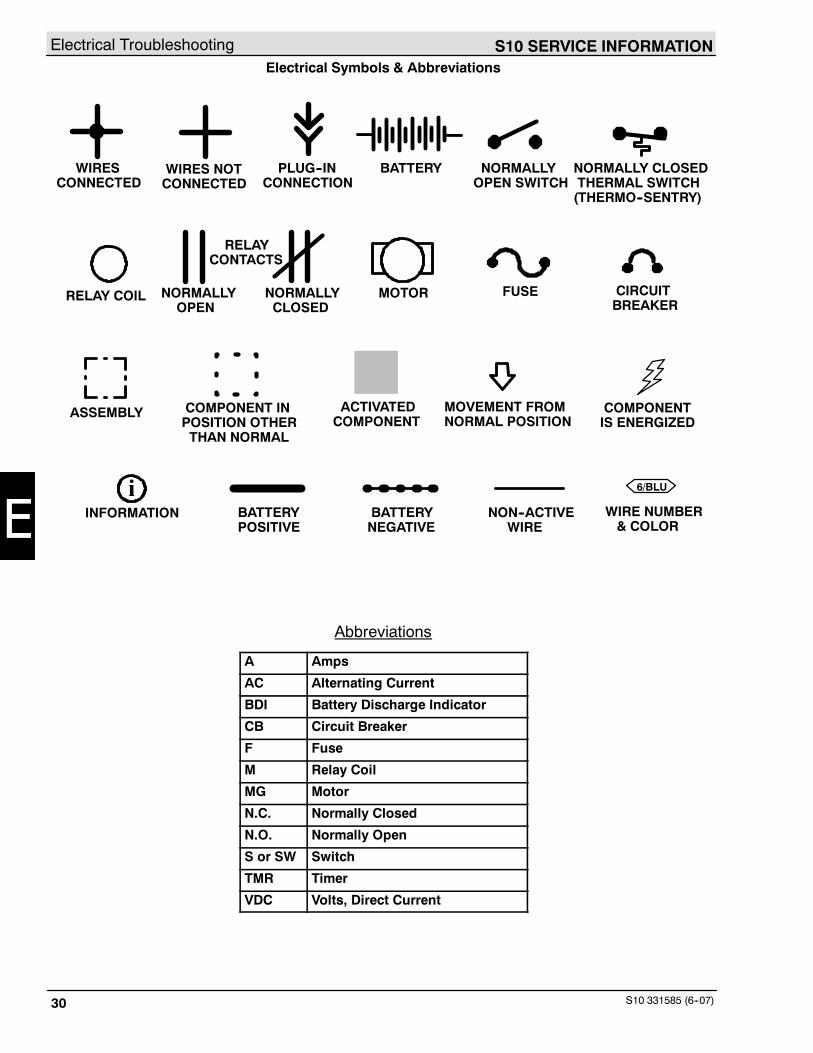
Electrical Symbols & Abbreviations
6/BLUi
WIRESCONNECTED
WIRES NOTCONNECTED
PLUG--INCONNECTION
BATTERY NORMALLYOPEN SWITCH
NORMALLY CLOSEDTHERMAL SWITCH(THERMO--SENTRY)
RELAY COIL MOTORNORMALLYOPEN
NORMALLYCLOSED
RELAYCONTACTS
FUSE CIRCUITBREAKER
ASSEMBLY COMPONENT INPOSITION OTHERTHAN NORMAL
ACTIVATEDCOMPONENT
MOVEMENT FROMNORMAL POSITION
COMPONENTIS ENERGIZED
INFORMATION BATTERYPOSITIVE
BATTERYNEGATIVE
NON--ACTIVEWIRE
WIRE NUMBER& COLOR
Abbreviations
A Amps
AC Alternating Current
BDI Battery Discharge Indicator
CB Circuit Breaker
F Fuse
M Relay Coil
MG Motor
N.C. Normally Closed
N.O. Normally Open
S or SW Switch
TMR Timer
VDC Volts, Direct Current
S10 SERVICE INFORMATION Electrical Troubleshooting
S10 331585 (6--07) 31
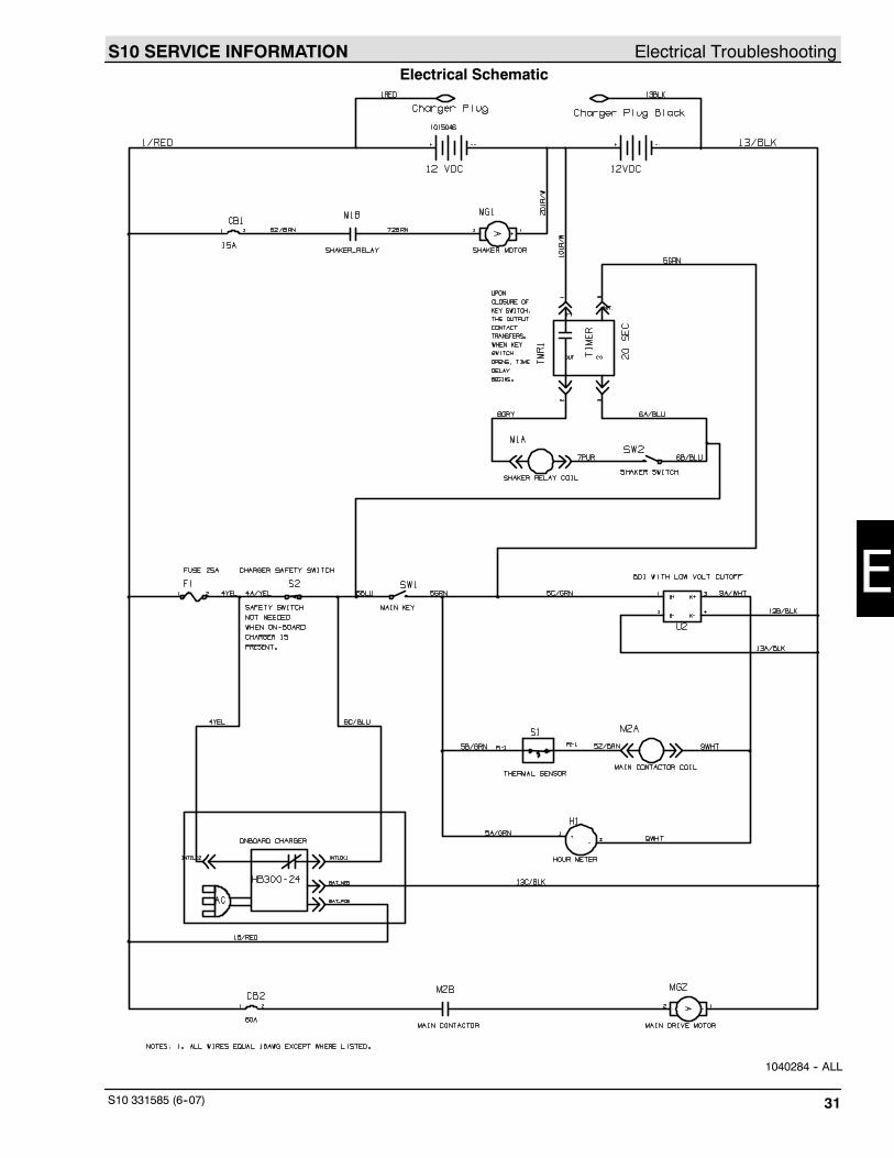
Electrical Schematic
1040284 -- ALL
Electrical Troubleshooting S10 SERVICE INFORMATION
S10 331585 (6--07)32
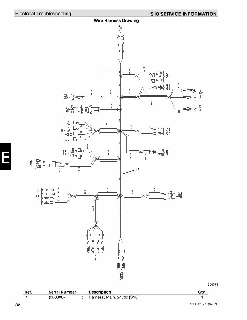
Wire Harness Drawing
1
354572
Ref. Serial Number Description Qty.1 (000000-- ) Harness, Main, 24vdc [S10] 1
S10 SERVICE INFORMATION Electrical Troubleshooting
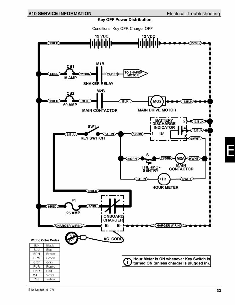
S10 331585 (6--07) 33
Key OFF Power Distribution
12 VDC 12 VDC
CB2
CB1
15 AMP
60 AMP
F1
CHARGER WIRING
M1B
M2B
MG2
M2A
25 AMP
AC CORD
B+ B--
ONBOARDCHARGER
SW1
KEY SWITCH
S1
THERMO--SENTRY
MAINCONTACTOR
HOUR METER
1
2
3
4
U2
BATTERY
INDICATORDISCHARGE
MAIN CONTACTOR
SHAKER RELAY
MAIN DRIVE MOTOR
4/YEL
6/BLU
52/BRN
62/BRN
5/GRN
72/BRN
BLK
1/RED
1/RED
1/RED
1/RED 13/BLK
13/BLK
13/BLKBLK
6/BLU
5/GRN
5/GRN
5/GRN
9/WHT
CHARGER WIRING
Conditions: Key OFF, Charger OFF
TO SHAKERMOTOR
13/BLK
9/WHTH1+ --
9/WHT
Wiring Color Codes
i Hour Meter is ON whenever Key Switch isturned ON (unless charger is plugged in).
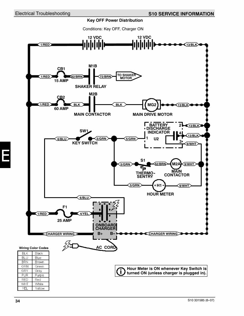
Electrical Troubleshooting S10 SERVICE INFORMATION
S10 331585 (6--07)34
Key OFF Power Distribution
12 VDC 12 VDC
CB2
CB1
15 AMP
60 AMP
F1
M1B
M2B
MG2
M2A
AC CORD
B+ B--
ONBOARDCHARGER
SW1
KEY SWITCH
S1
THERMO--SENTRY
MAINCONTACTOR
HOUR METER
1
2
MAIN CONTACTOR
SHAKER RELAY
MAIN DRIVE MOTOR
CHARGER WIRING
4/YEL
6/BLU
52/BRN
62/BRN
5/GRN
72/BRN
BLK
1/RED
1/RED
1/RED
1/RED 13/BLK
13/BLK
13/BLKBLK
6/BLU
5/GRN
5/GRN
5/GRN
9/WHT
CHARGER WIRING
Conditions: Key OFF, Charger ON
TO SHAKERMOTOR
U2
BATTERY
INDICATORDISCHARGE
3
4
H1+ --
9/WHT
9/WHT
13/BLK
25 AMP
Wiring Color Codes
i Hour Meter is ON whenever Key Switch isturned ON (unless charger is plugged in).
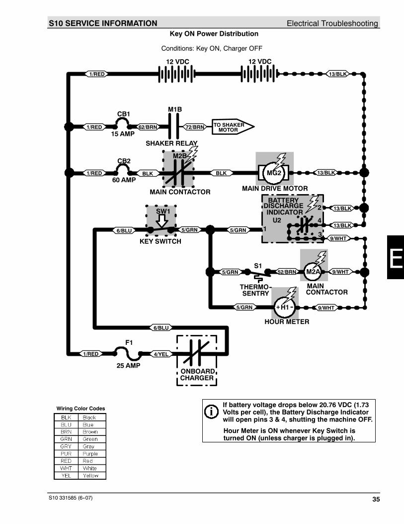
S10 SERVICE INFORMATION Electrical Troubleshooting
S10 331585 (6--07) 35
Key ON Power Distribution
Conditions: Key ON, Charger OFF
12 VDC 12 VDC
CB2
CB1
15 AMP
60 AMP
F1
TO SHAKERMOTOR
M1B
M2B
MG2
M2A
4/YEL
6/BLU
H1
ONBOARDCHARGER
SW1
KEY SWITCH
S1
THERMO--SENTRY
MAINCONTACTOR
HOUR METER
1
MAIN CONTACTOR
+ --
SHAKER RELAY
52/BRN
62/BRN
5/GRN
72/BRN
BLK
MAIN DRIVE MOTOR
1/RED
1/RED
1/RED
1/RED 13/BLK
13/BLKBLK
6/BLU
5/GRN
5/GRN
5/GRN
9/WHT
iIf battery voltage drops below 20.76 VDC (1.73Volts per cell), the Battery Discharge Indicatorwill open pins 3 & 4, shutting the machine OFF.
2 13/BLKBATTERY
INDICATORDISCHARGE
3
4U213/BLK
H1+ --
9/WHT
9/WHT
25 AMP
Wiring Color Codes
Hour Meter is ON whenever Key Switch isturned ON (unless charger is plugged in).
Electrical Troubleshooting S10 SERVICE INFORMATION
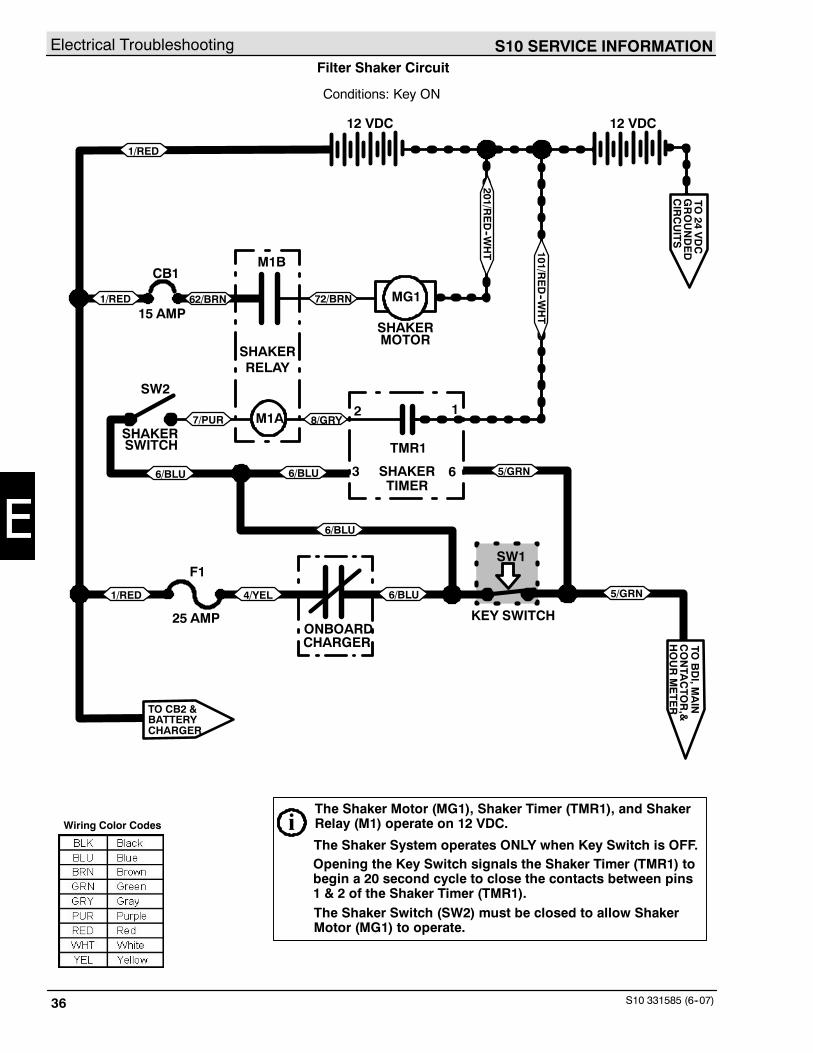
S10 331585 (6--07)36
Filter Shaker Circuit
12 VDC 12 VDC
CB1
15 AMP
M1B
MG1
SHAKER
62/BRN 72/BRN1/RED
Conditions: Key ON
TO CB2 &BATTERY
1/RED
4/YEL
ONBOARDCHARGER
1/RED
SHAKERMOTOR
6/BLU
SW1
KEY SWITCH
12
3 6
RELAY
SHAKERTIMER
SWITCH
SW2
M1ASHAKER
6/BLU
6/BLU6/BLU 5/GRN
8/GRY7/PUR
TO24
VDC
GROUNDED
CIRCUITS
5/GRN
TOBDI,M
AIN
CONTA
CTO
R,&
HOURMETER
CHARGER
TMR1
201/RED--W
HT 101/R
ED--W
HT
iThe Shaker Motor (MG1), Shaker Timer (TMR1), and ShakerRelay (M1) operate on 12 VDC.
The Shaker System operates ONLY when Key Switch is OFF.Opening the Key Switch signals the Shaker Timer (TMR1) tobegin a 20 second cycle to close the contacts between pins1 & 2 of the Shaker Timer (TMR1).The Shaker Switch (SW2) must be closed to allow ShakerMotor (MG1) to operate.
F1
25 AMP
Wiring Color Codes
S10 SERVICE INFORMATION Electrical Troubleshooting
S10 331585 (6--07) 37
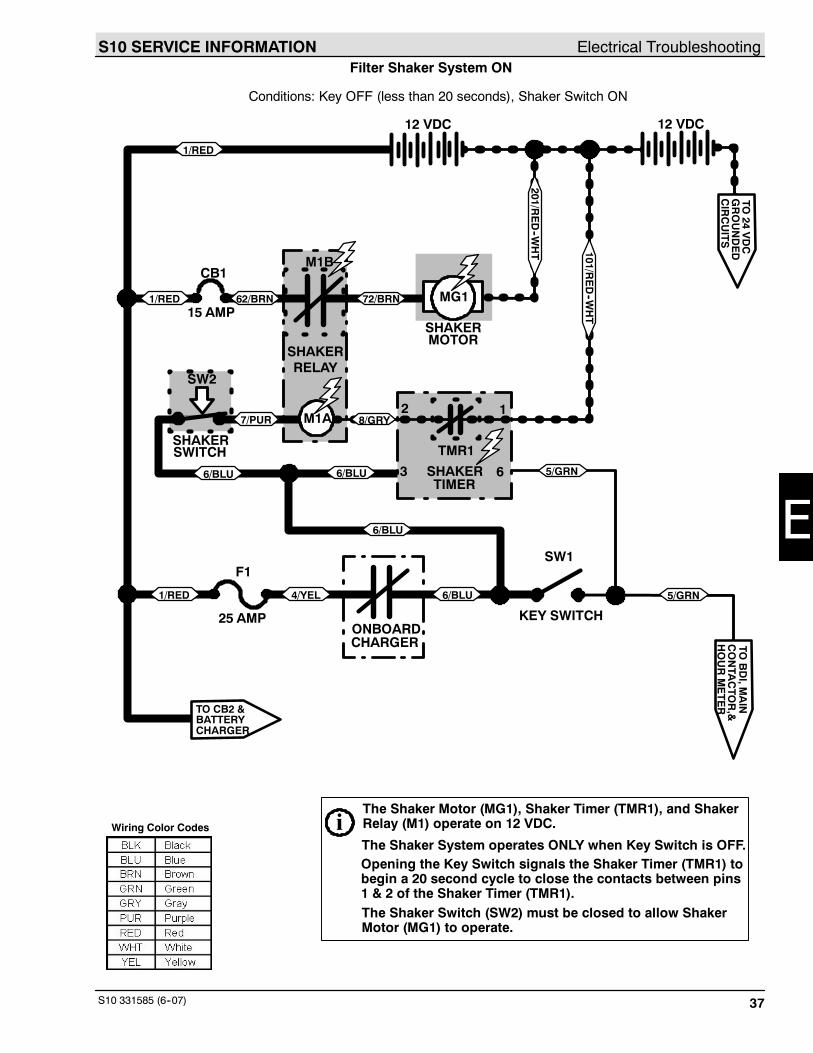
Filter Shaker System ON
12 VDC 12 VDC
CB1
15 AMP
M1B
MG1
SHAKER
62/BRN 72/BRN1/RED
Conditions: Key OFF (less than 20 seconds), Shaker Switch ON
TO CB2 &BATTERY
1/RED
4/YEL
ONBOARDCHARGER
1/RED
SHAKERMOTOR
6/BLU
SW1
KEY SWITCH
12
3 6
RELAY
SHAKERTIMER
SWITCH
SW2
M1A
6/BLU
6/BLU6/BLU 5/GRN
8/GRY7/PUR
TO24
VDC
GROUNDED
CIRCUITS
5/GRN
TOBDI,M
AIN
CONTA
CTO
R,&
HOURMETER
CHARGER
TMR1
201/RED--W
HT 101/R
ED--W
HT
iThe Shaker Motor (MG1), Shaker Timer (TMR1), and ShakerRelay (M1) operate on 12 VDC.
The Shaker System operates ONLY when Key Switch is OFF.Opening the Key Switch signals the Shaker Timer (TMR1) tobegin a 20 second cycle to close the contacts between pins1 & 2 of the Shaker Timer (TMR1).The Shaker Switch (SW2) must be closed to allow ShakerMotor (MG1) to operate.
SHAKER
F1
25 AMP
Wiring Color Codes


We Need Your Help...As part of Tennant’s Zero Defects Program, we want to know about errors you havefound or suggestions you may have regarding our machine manuals. If you find anerror or have a suggestion, please complete this postage-paid form and mail it to us.Thank you for helping us make zero defects a way of life at Tennant.
Manual No. Rev. No. Publish Date PageMachine - Report Error - Suggestion
Name Date
Customer Number
CompanyAddress
City/State/Zip Code

Tapehere Foldalongdottedlines
NOPOSTAGENECESSARYIFMAILEDINTHE
UNITEDSATES
BUSINESSREPLYMAIL FIRSTCLASSMAILPERMITNO.94MINNEAPOLIS,MN
POSTAGEWILLBEPAIDBYADDRESSEE
TechnicalPublications#15701NorthLilacDriveP.O.Box1452Minneapolis,MN55440--9947
TENNANTCOMPANY

We Need Your Help...As part of Tennant’s Zero Defects Program, we want to know about errors you havefound or suggestions you may have regarding our machine manuals. If you find anerror or have a suggestion, please complete this postage-paid form and mail it to us.Thank you for helping us make zero defects a way of life at Tennant.
Manual No. Rev. No. Publish Date PageMachine - Report Error - Suggestion
Name Date
Customer Number
CompanyAddress
City/State/Zip Code
Tapehere Foldalongdottedlines
NOPOSTAGENECESSARYIFMAILEDINTHE
UNITEDSATES
BUSINESSREPLYMAIL FIRSTCLASSMAILPERMITNO.94MINNEAPOLIS,MN
POSTAGEWILLBEPAIDBYADDRESSEE
TechnicalPublications#15701NorthLilacDriveP.O.Box1452Minneapolis,MN55440--9947
TENNANTCOMPANY