Embed Size (px)
Citation preview

ElectricService
Handbook
June 2013
Single‐Family Residential ProjectsPermanent & Temporary Service

� 2013 by Puget Sound Energy
All rights reserved. No part of this book may be reproduced or transmitted in any form or byany means, electronic or mechanical, including photocopying, recording, or
information storage and retrieval system, without permission from Puget Sound Energy (PSE).
Puget Sound EnergyStandards Department
P.O. Box 97034 EST-07WBellevue, WA 98009-9734
1-888-225-5773

TABLE OF CONTENTS i
ELECTRIC SERVICE HANDBOOK/SINGLE‐FAMILY RESIDENTIAL PROJECTS
Table of Contents
Preface
What this handbook contains vii. . . . . . . . . . . . . . . . . . . . . . . . . . . . . . . . . . . . . . . . . . . . . . . . . . . . . .
PSE’s service availability vii. . . . . . . . . . . . . . . . . . . . . . . . . . . . . . . . . . . . . . . . . . . . . . . . . .Glossary of terms used in this handbook vii. . . . . . . . . . . . . . . . . . . . . . . . . . . . . . . . . . . . . .
Codes, permits, and inspections vii. . . . . . . . . . . . . . . . . . . . . . . . . . . . . . . . . . . . . . . . . . . . . . . . . . . .Electrical service equipment inspection viii. . . . . . . . . . . . . . . . . . . . . . . . . . . . . . . . . . . . . . .
Reconnecting existing electric service after repair or replacement viii. . . . . . . . . . . . . . . . . . . . . . . . .
Scheduling viii. . . . . . . . . . . . . . . . . . . . . . . . . . . . . . . . . . . . . . . . . . . . . . . . . . . . . . . . . . . . . . . . . . . .
Underground or overhead service? viii. . . . . . . . . . . . . . . . . . . . . . . . . . . . . . . . . . . . . . . . . . . . . . . . .Which type of electrical system is available in your area? viii. . . . . . . . . . . . . . . . . . . . . . . . .Underground service ix. . . . . . . . . . . . . . . . . . . . . . . . . . . . . . . . . . . . . . . . . . . . . . . . . . . . . .Overhead service ix. . . . . . . . . . . . . . . . . . . . . . . . . . . . . . . . . . . . . . . . . . . . . . . . . . . . . . . . .Questions or assistance ix. . . . . . . . . . . . . . . . . . . . . . . . . . . . . . . . . . . . . . . . . . . . . . . . . . . .
Other electric service information x. . . . . . . . . . . . . . . . . . . . . . . . . . . . . . . . . . . . . . . . . . . . . . . . . .
How to contact Puget Sound Energy x. . . . . . . . . . . . . . . . . . . . . . . . . . . . . . . . . . . . . . . . . . . . . . . .
PSE’s service providers x. . . . . . . . . . . . . . . . . . . . . . . . . . . . . . . . . . . . . . . . . . . . . . . . . . . . . . . . . .
Overview: New Permanent and Temporary Electric Service Hookupto Existing PSE Power Facilities for Single-Family Residential Projects xi. . . . . . . . . . . . . . . .
Chapter 1: Steps to a Successful Permanent Electric Service Installationfor Single-Family Residences
Definitions 1. . . . . . . . . . . . . . . . . . . . . . . . . . . . . . . . . . . . . . . . . . . . . . . . . . . . . . . . . . . . . . . . . . .
Service installation responsibilities 1. . . . . . . . . . . . . . . . . . . . . . . . . . . . . . . . . . . . . . . . . . . . . . . . .
Puget Sound Energy 1. . . . . . . . . . . . . . . . . . . . . . . . . . . . . . . . . . . . . . . . . . . . . . . . . . . . . .Customer 1. . . . . . . . . . . . . . . . . . . . . . . . . . . . . . . . . . . . . . . . . . . . . . . . . . . . . . . . . . . . . . .
Starting the installation process 2. . . . . . . . . . . . . . . . . . . . . . . . . . . . . . . . . . . . . . . . . . . . . . . . . . . .Setting up an account or to order a new service 2. . . . . . . . . . . . . . . . . . . . . . . . . . . . . . . . .Will your project need engineering? 2. . . . . . . . . . . . . . . . . . . . . . . . . . . . . . . . . . . . . . . . . .
Choosing the right service size 3. . . . . . . . . . . . . . . . . . . . . . . . . . . . . . . . . . . . . . . . . . . . . . . . . . . .Service voltages 3. . . . . . . . . . . . . . . . . . . . . . . . . . . . . . . . . . . . . . . . . . . . . . . . . . . . . . . . .Service sizes 3. . . . . . . . . . . . . . . . . . . . . . . . . . . . . . . . . . . . . . . . . . . . . . . . . . . . . . . . . . . .Sizes less than 200 A 3. . . . . . . . . . . . . . . . . . . . . . . . . . . . . . . . . . . . . . . . . . . . . . . . . . . . .
Determining an approved meter location 3. . . . . . . . . . . . . . . . . . . . . . . . . . . . . . . . . . . . . . . . . . . . .
Customer-installed meter base/socket location 3. . . . . . . . . . . . . . . . . . . . . . . . . . . . . . . . . .Know what’s below: Call 811 before you dig 4. . . . . . . . . . . . . . . . . . . . . . . . . . . . . . . . . . . . . . . . .
Coordinating utility trenching and construction 5. . . . . . . . . . . . . . . . . . . . . . . . . . . . . . . . . . . . . . .
Continued on next page

TABLE OF CONTENTSii
ELECTRIC SERVICE HANDBOOK/SINGLE‐FAMILY RESIDENTIAL PROJECTS
Transformer locations 5. . . . . . . . . . . . . . . . . . . . . . . . . . . . . . . . . . . . . . . . . . . . . . . . . . . . . . . . . . .
Liquefied propane tanks: clearances from ignition source 8. . . . . . . . . . . . . . . . . . . . . . . . . . . . . . .
Outbuildings 9. . . . . . . . . . . . . . . . . . . . . . . . . . . . . . . . . . . . . . . . . . . . . . . . . . . . . . . . . . . . . . . . . . .
Service line installation responsibilities for outbuildings 9. . . . . . . . . . . . . . . . . . . . . . . . . .Cost for service 10. . . . . . . . . . . . . . . . . . . . . . . . . . . . . . . . . . . . . . . . . . . . . . . . . . . . . . . . . . . . . . . .
Power quality, voltage flicker 10. . . . . . . . . . . . . . . . . . . . . . . . . . . . . . . . . . . . . . . . . . . . . . . . . . . . .
Chapter 2: Permanent Underground Service
Steps to a successful underground service installation 11. . . . . . . . . . . . . . . . . . . . . . . . . . . . . . . . . .
Selecting a meter base/socket location 12. . . . . . . . . . . . . . . . . . . . . . . . . . . . . . . . . . . . . . . . . . . . . .
Multiple metered services 12. . . . . . . . . . . . . . . . . . . . . . . . . . . . . . . . . . . . . . . . . . . . . . . . . .Service line trenches 12. . . . . . . . . . . . . . . . . . . . . . . . . . . . . . . . . . . . . . . . . . . . . . . . . . . . . . . . . . . .
Trench and backfill requirements 12. . . . . . . . . . . . . . . . . . . . . . . . . . . . . . . . . . . . . . . . . . . .Customer-installed service line conduit 12. . . . . . . . . . . . . . . . . . . . . . . . . . . . . . . . . . . . . . .Customer-installed service line conduit installation requirements 13. . . . . . . . . . . . . . . . . . .
Continuous and discontinuous conduit systems 13. . . . . . . . . . . . . . . . . . . . . . . . . . . . . . . . . . . . . . .
When to choose continuous conduit 14. . . . . . . . . . . . . . . . . . . . . . . . . . . . . . . . . . . . . . . . . .When to choose discontinuous conduit 15. . . . . . . . . . . . . . . . . . . . . . . . . . . . . . . . . . . . . . .
Service entrance equipment 16. . . . . . . . . . . . . . . . . . . . . . . . . . . . . . . . . . . . . . . . . . . . . . . . . . . . . . .
Installation requirements 16. . . . . . . . . . . . . . . . . . . . . . . . . . . . . . . . . . . . . . . . . . . . . . . . . . .Service entrance conduit size 16. . . . . . . . . . . . . . . . . . . . . . . . . . . . . . . . . . . . . . . . . . . . . . .
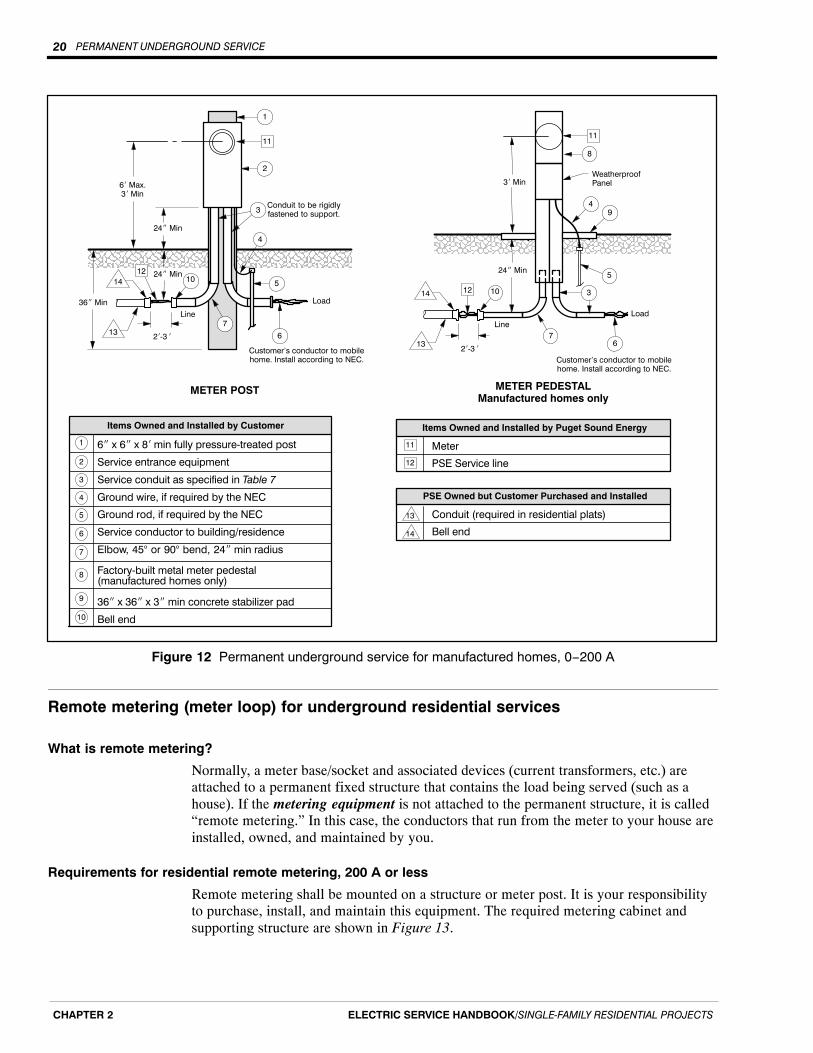
Permanent underground service for manufactured homes, 0−200 A 19. . . . . . . . . . . . . . . . . . . . . . . .
Service equipment installation 19. . . . . . . . . . . . . . . . . . . . . . . . . . . . . . . . . . . . . . . . . . . . . .Meter base/socket requirements 19. . . . . . . . . . . . . . . . . . . . . . . . . . . . . . . . . . . . . . . . . . . . .
Remote metering (meter loop) for underground residential services 20. . . . . . . . . . . . . . . . . . . . . . .What is remote metering? 20. . . . . . . . . . . . . . . . . . . . . . . . . . . . . . . . . . . . . . . . . . . . . . . . . .Requirements for residential remote metering, 200 A or less 20. . . . . . . . . . . . . . . . . . . . . .400 A and larger panels 21. . . . . . . . . . . . . . . . . . . . . . . . . . . . . . . . . . . . . . . . . . . . . . . . . . .Remote services greater than 800 A 21. . . . . . . . . . . . . . . . . . . . . . . . . . . . . . . . . . . . . . . . . .Meter post and pedestal locations 21. . . . . . . . . . . . . . . . . . . . . . . . . . . . . . . . . . . . . . . . . . . .
Chapter 3: Permanent Overhead Service
Steps to a successful overhead service installation 23. . . . . . . . . . . . . . . . . . . . . . . . . . . . . . . . . . . . .
Selecting a meter base/socket location 23. . . . . . . . . . . . . . . . . . . . . . . . . . . . . . . . . . . . . . . . . . . . . .
Clearance requirements 24. . . . . . . . . . . . . . . . . . . . . . . . . . . . . . . . . . . . . . . . . . . . . . . . . . . . . . . . . .
Service line ground clearance 24. . . . . . . . . . . . . . . . . . . . . . . . . . . . . . . . . . . . . . . . . . . . . . .Minimum clearances from structures, building openings, and gas meters 25. . . . . . . . . . . . .Intermediate service pole 26. . . . . . . . . . . . . . . . . . . . . . . . . . . . . . . . . . . . . . . . . . . . . . . . . .
Service mast 26. . . . . . . . . . . . . . . . . . . . . . . . . . . . . . . . . . . . . . . . . . . . . . . . . . . . . . . . . . . . . . . . . . .
Service mast requirements 26. . . . . . . . . . . . . . . . . . . . . . . . . . . . . . . . . . . . . . . . . . . . . . . . .Height requirements 26. . . . . . . . . . . . . . . . . . . . . . . . . . . . . . . . . . . . . . . . . . . . . . . . . . . . . .Additional mast supports (guy or brace) 29. . . . . . . . . . . . . . . . . . . . . . . . . . . . . . . . . . . . . . .Screw-in service knobs 29. . . . . . . . . . . . . . . . . . . . . . . . . . . . . . . . . . . . . . . . . . . . . . . . . . . .
Service entrance equipment installation requirements 29. . . . . . . . . . . . . . . . . . . . . . . . . . . . . . . . . . .

TABLE OF CONTENTS iii
ELECTRIC SERVICE HANDBOOK/SINGLE‐FAMILY RESIDENTIAL PROJECTS
Manufactured homes 29. . . . . . . . . . . . . . . . . . . . . . . . . . . . . . . . . . . . . . . . . . . . . . . . . . . . . . . . . . . .
Meter base/socket installation requirements for manufactured homes 30. . . . . . . . . . . . . . . .Customer-owned meter pole 30. . . . . . . . . . . . . . . . . . . . . . . . . . . . . . . . . . . . . . . . . . . . . . . . . . . . . .
Meter pole requirements 30. . . . . . . . . . . . . . . . . . . . . . . . . . . . . . . . . . . . . . . . . . . . . . . . . . .Installation requirements 30. . . . . . . . . . . . . . . . . . . . . . . . . . . . . . . . . . . . . . . . . . . . . . . . . . .
Chapter 4: Primary Line Extensions
Customer responsibility 33. . . . . . . . . . . . . . . . . . . . . . . . . . . . . . . . . . . . . . . . . . . . . . . . . . . . . . . . . .
Inspection/coordination 33. . . . . . . . . . . . . . . . . . . . . . . . . . . . . . . . . . . . . . . . . . . . . . . . . . . . . . . . . .
Site preparation 33. . . . . . . . . . . . . . . . . . . . . . . . . . . . . . . . . . . . . . . . . . . . . . . . . . . . . . . . . . . . . . . .
Customer-provided trench 33. . . . . . . . . . . . . . . . . . . . . . . . . . . . . . . . . . . . . . . . . . . . . . . . . . . . . . . .Trench width 33. . . . . . . . . . . . . . . . . . . . . . . . . . . . . . . . . . . . . . . . . . . . . . . . . . . . . . . . . . . .Trench excavating requirements 35. . . . . . . . . . . . . . . . . . . . . . . . . . . . . . . . . . . . . . . . . . . . .Trench and backfill requirements for electric 35. . . . . . . . . . . . . . . . . . . . . . . . . . . . . . . . . . .Trench and backfill requirements if a natural gas line is in the trench 36. . . . . . . . . . . . . . . .
Vaults 36. . . . . . . . . . . . . . . . . . . . . . . . . . . . . . . . . . . . . . . . . . . . . . . . . . . . . . . . . . . . . . . . . . . . . . . .
Vault excavation procedure 36. . . . . . . . . . . . . . . . . . . . . . . . . . . . . . . . . . . . . . . . . . . . . . . . .Vault location and access 38. . . . . . . . . . . . . . . . . . . . . . . . . . . . . . . . . . . . . . . . . . . . . . . . . .Vault backfill material 38. . . . . . . . . . . . . . . . . . . . . . . . . . . . . . . . . . . . . . . . . . . . . . . . . . . . .
Continuous conduit systems 39. . . . . . . . . . . . . . . . . . . . . . . . . . . . . . . . . . . . . . . . . . . . . . . . . . . . . .
Customer-supplied conduits 39. . . . . . . . . . . . . . . . . . . . . . . . . . . . . . . . . . . . . . . . . . . . . . . . . . . . . . .
Terminating conduit at transformer 39. . . . . . . . . . . . . . . . . . . . . . . . . . . . . . . . . . . . . . . . . . . . . . . . .
Chapter 5: Meter Installation
Service rating options 41. . . . . . . . . . . . . . . . . . . . . . . . . . . . . . . . . . . . . . . . . . . . . . . . . . . . . . . . . . .
Responsibilities 41. . . . . . . . . . . . . . . . . . . . . . . . . . . . . . . . . . . . . . . . . . . . . . . . . . . . . . . . . . . . . . . .
Puget Sound Energy 41. . . . . . . . . . . . . . . . . . . . . . . . . . . . . . . . . . . . . . . . . . . . . . . . . . . . . .Customer 41. . . . . . . . . . . . . . . . . . . . . . . . . . . . . . . . . . . . . . . . . . . . . . . . . . . . . . . . . . . . . . .
Meter bases/sockets 41. . . . . . . . . . . . . . . . . . . . . . . . . . . . . . . . . . . . . . . . . . . . . . . . . . . . . . . . . . . . .
General requirements 41. . . . . . . . . . . . . . . . . . . . . . . . . . . . . . . . . . . . . . . . . . . . . . . . . . . . .Meter base/socket location 42. . . . . . . . . . . . . . . . . . . . . . . . . . . . . . . . . . . . . . . . . . . . . . . . .Grounding requirements 42. . . . . . . . . . . . . . . . . . . . . . . . . . . . . . . . . . . . . . . . . . . . . . . . . . .
Clearance requirements for meter installations 42. . . . . . . . . . . . . . . . . . . . . . . . . . . . . . . . . . . . . . . .
200 A services 44. . . . . . . . . . . . . . . . . . . . . . . . . . . . . . . . . . . . . . . . . . . . . . . . . . . . . . . . . . . . . . . . .
Single-family residential 44. . . . . . . . . . . . . . . . . . . . . . . . . . . . . . . . . . . . . . . . . . . . . . . . . . .Underground 44. . . . . . . . . . . . . . . . . . . . . . . . . . . . . . . . . . . . . . . . . . . . . . . . . . . . . . . . . . . .Overhead 44. . . . . . . . . . . . . . . . . . . . . . . . . . . . . . . . . . . . . . . . . . . . . . . . . . . . . . . . . . . . . . .Outbuildings (overhead or underground service) 44. . . . . . . . . . . . . . . . . . . . . . . . . . . . . . . .
400 A services 46. . . . . . . . . . . . . . . . . . . . . . . . . . . . . . . . . . . . . . . . . . . . . . . . . . . . . . . . . . . . . . . . .
Underground 46. . . . . . . . . . . . . . . . . . . . . . . . . . . . . . . . . . . . . . . . . . . . . . . . . . . . . . . . . . . .Overhead 47. . . . . . . . . . . . . . . . . . . . . . . . . . . . . . . . . . . . . . . . . . . . . . . . . . . . . . . . . . . . . . .Outbuildings (overhead or underground service) 47. . . . . . . . . . . . . . . . . . . . . . . . . . . . . . . .
400 A current transformer (CT) services 48. . . . . . . . . . . . . . . . . . . . . . . . . . . . . . . . . . . . . . . . . . . . .
Services over 400 A 49. . . . . . . . . . . . . . . . . . . . . . . . . . . . . . . . . . . . . . . . . . . . . . . . . . . . . . . . . . . . .

TABLE OF CONTENTSiv
ELECTRIC SERVICE HANDBOOK/SINGLE‐FAMILY RESIDENTIAL PROJECTS
Chapter 6: Temporary Services
What this chapter contains 51. . . . . . . . . . . . . . . . . . . . . . . . . . . . . . . . . . . . . . . . . . . . . . . . . . . . . . . .
Definition 51. . . . . . . . . . . . . . . . . . . . . . . . . . . . . . . . . . . . . . . . . . . . . . . . . . . . . . . . . . . . . . . . . . . . .
Obtaining your temporary service from existing power facilities 51. . . . . . . . . . . . . . . . . . . . . . . . . .
Scheduling 52. . . . . . . . . . . . . . . . . . . . . . . . . . . . . . . . . . . . . . . . . . . . . . . . . . . . . . . . . . . . . . . . . . . .
Customer charge for service 52. . . . . . . . . . . . . . . . . . . . . . . . . . . . . . . . . . . . . . . . . . . . . . . . . . . . . . .
Temporary meter base/socket requirements 52. . . . . . . . . . . . . . . . . . . . . . . . . . . . . . . . . . . . . . . . . . .
Temporary underground services 52. . . . . . . . . . . . . . . . . . . . . . . . . . . . . . . . . . . . . . . . . . . . . . . . . . .
Meter location 52. . . . . . . . . . . . . . . . . . . . . . . . . . . . . . . . . . . . . . . . . . . . . . . . . . . . . . . . . . .Trenching and excavation requirements 53. . . . . . . . . . . . . . . . . . . . . . . . . . . . . . . . . . . . . . .Underground temporary service installation process 54. . . . . . . . . . . . . . . . . . . . . . . . . . . . .
Temporary overhead services 56. . . . . . . . . . . . . . . . . . . . . . . . . . . . . . . . . . . . . . . . . . . . . . . . . . . . . .
Meter location 56. . . . . . . . . . . . . . . . . . . . . . . . . . . . . . . . . . . . . . . . . . . . . . . . . . . . . . . . . . .Service line path requirements 56. . . . . . . . . . . . . . . . . . . . . . . . . . . . . . . . . . . . . . . . . . . . . .Clearance requirements 56. . . . . . . . . . . . . . . . . . . . . . . . . . . . . . . . . . . . . . . . . . . . . . . . . . . .Overhead temporary service installation process 57. . . . . . . . . . . . . . . . . . . . . . . . . . . . . . . .
Chapter 7: Disconnection and Modification of Service
Disconnection of your meter 59. . . . . . . . . . . . . . . . . . . . . . . . . . . . . . . . . . . . . . . . . . . . . . . . . . . . . .
Modified services 59. . . . . . . . . . . . . . . . . . . . . . . . . . . . . . . . . . . . . . . . . . . . . . . . . . . . . . . . . . . . . . .
Glossary 61. . . . . . . . . . . . . . . . . . . . . . . . . . . . . . . . . . . . . . . . . . . . . . . . . . . . . . . . . . . . . . .
List of Tables
Table 1 Types of electric services x. . . . . . . . . . . . . . . . . . . . . . . . . . . . . . . . . . . . . . . . . . . . . . . .
Table 2 Standard voltages for residential customers 3. . . . . . . . . . . . . . . . . . . . . . . . . . . . . . . . . .
Table 3 Service sizes available from PSE 3. . . . . . . . . . . . . . . . . . . . . . . . . . . . . . . . . . . . . . . . . .
Table 4 Color codes for locating utilities 4. . . . . . . . . . . . . . . . . . . . . . . . . . . . . . . . . . . . . . . . . . .
Table 5 Clearances for padmount transformers 5. . . . . . . . . . . . . . . . . . . . . . . . . . . . . . . . . . . . . .
Table 6 Service line installation responsibilities 9. . . . . . . . . . . . . . . . . . . . . . . . . . . . . . . . . . . . .
Table 7 Current transformer (CT) enclosure dimensions (minimum) 49. . . . . . . . . . . . . . . . . . . . .
Table 8 Example of overhead and underground modified service 60. . . . . . . . . . . . . . . . . . . . . . . .
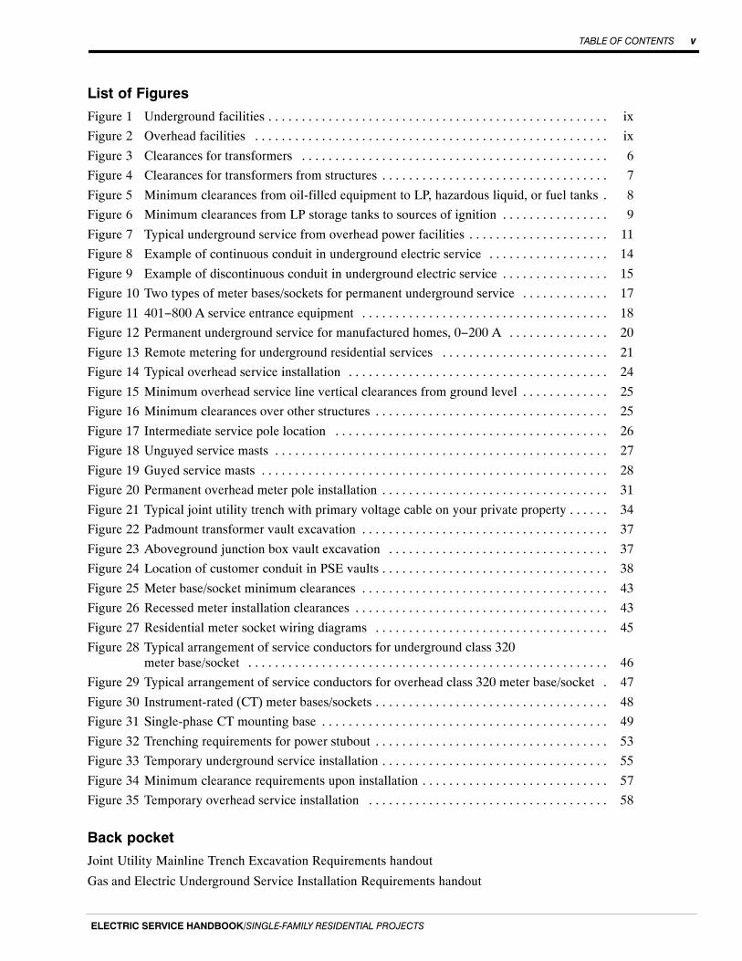
TABLE OF CONTENTS v
ELECTRIC SERVICE HANDBOOK/SINGLE‐FAMILY RESIDENTIAL PROJECTS
List of Figures
Figure 1 Underground facilities ix. . . . . . . . . . . . . . . . . . . . . . . . . . . . . . . . . . . . . . . . . . . . . . . . . . .
Figure 2 Overhead facilities ix. . . . . . . . . . . . . . . . . . . . . . . . . . . . . . . . . . . . . . . . . . . . . . . . . . . . .
Figure 3 Clearances for transformers 6. . . . . . . . . . . . . . . . . . . . . . . . . . . . . . . . . . . . . . . . . . . . . .
Figure 4 Clearances for transformers from structures 7. . . . . . . . . . . . . . . . . . . . . . . . . . . . . . . . . .
Figure 5 Minimum clearances from oil-filled equipment to LP, hazardous liquid, or fuel tanks 8.
Figure 6 Minimum clearances from LP storage tanks to sources of ignition 9. . . . . . . . . . . . . . . .
Figure 7 Typical underground service from overhead power facilities 11. . . . . . . . . . . . . . . . . . . . .
Figure 8 Example of continuous conduit in underground electric service 14. . . . . . . . . . . . . . . . . .
Figure 9 Example of discontinuous conduit in underground electric service 15. . . . . . . . . . . . . . . .
Figure 10 Two types of meter bases/sockets for permanent underground service 17. . . . . . . . . . . . .
Figure 11 401−800 A service entrance equipment 18. . . . . . . . . . . . . . . . . . . . . . . . . . . . . . . . . . . . .
Figure 12 Permanent underground service for manufactured homes, 0−200 A 20. . . . . . . . . . . . . . .
Figure 13 Remote metering for underground residential services 21. . . . . . . . . . . . . . . . . . . . . . . . .
Figure 14 Typical overhead service installation 24. . . . . . . . . . . . . . . . . . . . . . . . . . . . . . . . . . . . . . .
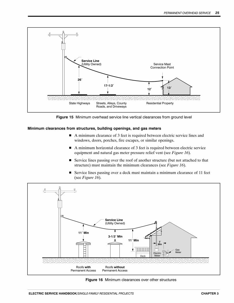
Figure 15 Minimum overhead service line vertical clearances from ground level 25. . . . . . . . . . . . .
Figure 16 Minimum clearances over other structures 25. . . . . . . . . . . . . . . . . . . . . . . . . . . . . . . . . . .
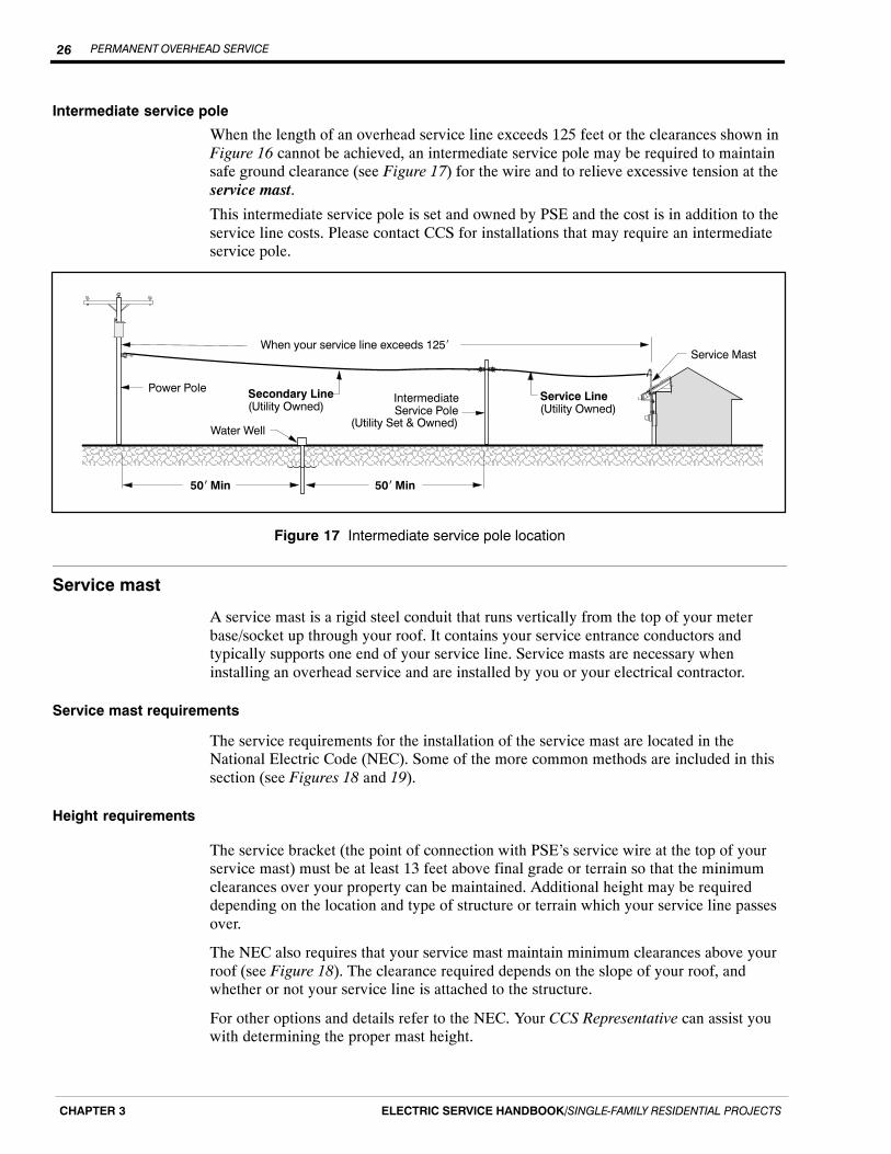
Figure 17 Intermediate service pole location 26. . . . . . . . . . . . . . . . . . . . . . . . . . . . . . . . . . . . . . . . .
Figure 18 Unguyed service masts 27. . . . . . . . . . . . . . . . . . . . . . . . . . . . . . . . . . . . . . . . . . . . . . . . . .
Figure 19 Guyed service masts 28. . . . . . . . . . . . . . . . . . . . . . . . . . . . . . . . . . . . . . . . . . . . . . . . . . . .
Figure 20 Permanent overhead meter pole installation 31. . . . . . . . . . . . . . . . . . . . . . . . . . . . . . . . . .
Figure 21 Typical joint utility trench with primary voltage cable on your private property 34. . . . . .
Figure 22 Padmount transformer vault excavation 37. . . . . . . . . . . . . . . . . . . . . . . . . . . . . . . . . . . . .
Figure 23 Aboveground junction box vault excavation 37. . . . . . . . . . . . . . . . . . . . . . . . . . . . . . . . .
Figure 24 Location of customer conduit in PSE vaults 38. . . . . . . . . . . . . . . . . . . . . . . . . . . . . . . . . .
Figure 25 Meter base/socket minimum clearances 43. . . . . . . . . . . . . . . . . . . . . . . . . . . . . . . . . . . . .
Figure 26 Recessed meter installation clearances 43. . . . . . . . . . . . . . . . . . . . . . . . . . . . . . . . . . . . . .
Figure 27 Residential meter socket wiring diagrams 45. . . . . . . . . . . . . . . . . . . . . . . . . . . . . . . . . . .
Figure 28 Typical arrangement of service conductors for underground class 320meter base/socket 46. . . . . . . . . . . . . . . . . . . . . . . . . . . . . . . . . . . . . . . . . . . . . . . . . . . . . .
Figure 29 Typical arrangement of service conductors for overhead class 320 meter base/socket 47.
Figure 30 Instrument-rated (CT) meter bases/sockets 48. . . . . . . . . . . . . . . . . . . . . . . . . . . . . . . . . . .
Figure 31 Single-phase CT mounting base 49. . . . . . . . . . . . . . . . . . . . . . . . . . . . . . . . . . . . . . . . . . .
Figure 32 Trenching requirements for power stubout 53. . . . . . . . . . . . . . . . . . . . . . . . . . . . . . . . . . .
Figure 33 Temporary underground service installation 55. . . . . . . . . . . . . . . . . . . . . . . . . . . . . . . . . .
Figure 34 Minimum clearance requirements upon installation 57. . . . . . . . . . . . . . . . . . . . . . . . . . . .
Figure 35 Temporary overhead service installation 58. . . . . . . . . . . . . . . . . . . . . . . . . . . . . . . . . . . .
Back pocket
Joint Utility Mainline Trench Excavation Requirements handout
Gas and Electric Underground Service Installation Requirements handout

TABLE OF CONTENTSvi
ELECTRIC SERVICE HANDBOOK/SINGLE‐FAMILY RESIDENTIAL PROJECTS

PREFACE vii
ELECTRIC SERVICE HANDBOOK/SINGLE‐FAMILY RESIDENTIAL PROJECTS
Preface
This handbook is your guide to Puget Sound Energy’s (PSE) requirements for new,altered/modified, or temporary electric service for permanent single-family residentialstructures. We have also included additional requirements for electric service tooutbuildings (barns, shops, pump houses, garages, etc.).
What this handbook contains
In this handbook you will find answers to questions such as:
� What are the installation requirements for permanent and temporary underground andoverhead service?
� How do I choose the right service size?
� What are the trenching requirements?
� How do I locate existing underground utilities before I dig?
PSE’s service availability
General boundaries for PSE’s gas and electric service territory are available on PSE.com.A Customer Construction Services (CCS) Representative can help you to determine theclosest available service line and can provide you with cost information for establishingnew service.
Glossary of terms used in this handbook
For your convenience, glossary words appear in bold italics throughout the text the firsttime they appear (e.g., meter pole).
Codes, permits, and inspections
This handbook should only be used as a guide. It does not cover all possible federal,state, or local code requirements. It is your responsibility to ensure that your projectcomplies with the most recent issue of the National Electric Code (NEC) and any otherfederal, state, or local codes that may apply.
This handbook shall not be interpreted to conflict with the regulations of the state ofWashington or other regulatory bodies having jurisdiction. PSE’s metering requirementsmay be more stringent. Local codes and requirements related to the planned work shouldbe addressed before any construction begins.
PREFACEviii
ELECTRIC SERVICE HANDBOOK/SINGLE‐FAMILY RESIDENTIAL PROJECTS
Electrical service equipment inspection
Once your service equipment is installed, the state of Washington, or the city withjurisdiction over your area, requires that your installation pass an electrical inspectionbefore PSE can energize your system.
NOTE: It is your responsibility to request an electrical inspection.
Electrical inspections for most areas in the PSE service territory are done by theWashington State Department of Labor and Industries. However, electrical inspectionsare performed by city personnel in several jurisdictions. Please consultPSE.com\PermitsandInspections for a list of the cities and current contact information.
Reconnecting existing electric service after repair or replacement
All electrical equipment and wiring on the customer side of the meter (including meterbase and service masts) are owned and maintained by the customer. Therefore, you areresponsible for any repair or replacement of storm-damaged or failed meteringequipment. If you must repair/replace equipment of this kind, your service may need tobe de-energized or disconnected.
For more information, refer to Chapter 7, Disconnection and Modification of Servicesection of this handbook or contact your CCS Representative at 1-888-321-7779.
Scheduling
The time needed for engineering, scheduling, and construction of the work will varydepending upon the complexity of the job and the volume of work requested by PSEcustomers. Contact your CCS Representative at 1-888-321-7779 for current constructionscheduling.
Underground or overhead service?
The two types of permanent services are: underground and overhead.
Which type of electrical system is available in your area?
You can determine if PSE’s system is underground or overhead by checking for ourfacilities along your road. If the power system is underground, you’ll see facilities likethose in Figure 1. If the power system is overhead, a series of poles similar to Figure 2will be visible.
Use Table 1 to help you determine which type of electrical service can be provided. Forhelp determining which type of system is in your area, call your CCS Representative at1-888-321-7779. If none of the items in Figures 1 or 2 exist in your area, or if you havequestions, call 1-888-321-7779 and a CCS Representative will be glad to assist you.
PREFACE ix
ELECTRIC SERVICE HANDBOOK/SINGLE‐FAMILY RESIDENTIAL PROJECTS
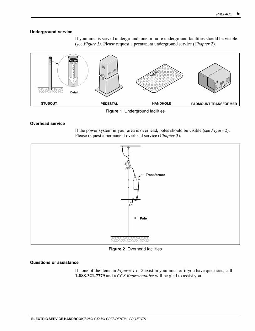
Underground service
If your area is served underground, one or more underground facilities should be visible(see Figure 1). Please request a permanent underground service (Chapter 2).
ÎÎÎÎÎÎÎÎÎÎ
STUBOUT HANDHOLEPEDESTAL PADMOUNT TRANSFORMER
Detail
ÂÂÂÂÂÂ
ÂÂÂÂÂÂÂÂÂÂÂÂÂÂÂÂÂÂÂÂÂÂÂÂÂÂÂÂÂÂÂÂÂÂÂÂÂÂÂÂ
Figure 1 Underground facilities
Overhead service
If the power system in your area is overhead, poles should be visible (see Figure 2).Please request a permanent overhead service (Chapter 3).
Pole
Transformer
ÎÎÎÎÎÎÎÎÎÎÎÎÎÎFigure 2 Overhead facilities
Questions or assistance
If none of the items in Figures 1 or 2 exist in your area, or if you have questions, call1-888-321-7779 and a CCS Representative will be glad to assist you.

PREFACEx
ELECTRIC SERVICE HANDBOOK/SINGLE‐FAMILY RESIDENTIAL PROJECTS
Table 1 Types of electric services
If availableelectrical
system is . . .And if . . .
Then yourservice linewill be . . .
Underground
� Your new meter location is less than 225 ft from ournearest padmount transformer (see Figure 1).NOTE: If your new meter location is more than 225 ftfrom our nearest underground transformer, an additionaltransformer may be required.
Underground
Overhead
� The new meter location is less than 200 ft from ournearest power pole.
� The service originates from the pole.
� The pole has a transformer on it (see Figure 2).
Underground
Overhead
� The new meter location is less than 125 ft from ournearest power pole.
� The pole has a transformer on it (see Figure 2).
� Your service line does not cross anyone else’s property.
Overhead orUnderground
NOTE: If your situation does not fit the criteria presented, please contact yourCCS Representative.
Other electric service information
If you need information on the installation of permanent or temporary multifamily andnonresidential services you will find it in the PSE Electric Service Handbook forCommercial/Industrial and Multifamily Projects.All handbooks are available free of charge from PSE.
How to contact Puget Sound Energy
You can obtain further information by contacting us through the following:
� PSE Customer Construction Services (CCS) at 1-888-321-7779Monday thru Friday, 7 a.m. − 5 p.m.
� PSE Energy Advisors at 1-800-562-1482Monday thru Friday, 8 a.m. − 5 p.m.
� PSE.com/CustomerConstruction
If you have an emergency, service delivery, or general billing question regarding youraccount, please call:� Customer Service at 1-888-225-5773; TTY 1-800-962-9498
24 hours a day, 7 days a week.
PSE’s service providers
PSE contracts with two partner companies to provide construction and engineeringservices: Potelco, Inc. and InfraSource Construction LLC. The project manager and theemployees who install your service may work for these service providers on PSE’sbehalf.
PREFACE xi
ELECTRIC SERVICE HANDBOOK/SINGLE‐FAMILY RESIDENTIAL PROJECTS
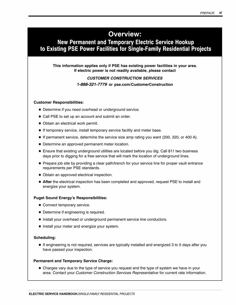
Overview:New Permanent and Temporary Electric Service Hookup
to Existing PSE Power Facilities for Single‐Family Residential Projects
This information applies only if PSE has existing power facilities in your area.If electric power is not readily available, please contact
CUSTOMER CONSTRUCTION SERVICES
1-888-321-7779 or pse.com/CustomerConstruction
Customer Responsibilities:
� Determine if you need overhead or underground service.
� Call PSE to set up an account and submit an order.
� Obtain an electrical work permit.
� If temporary service, install temporary service facility and meter base.
� If permanent service, determine the service size amp rating you want (200, 320, or 400 A).
� Determine an approved permanent meter location.
� Ensure that existing underground utilities are located before you dig. Call 811 two businessdays prior to digging for a free service that will mark the location of underground lines.
� Prepare job site by providing a clear path/trench for your service line for proper vault entrancerequirements per PSE standards.
� Obtain an approved electrical inspection.
� After the electrical inspection has been completed and approved, request PSE to install andenergize your system.
Puget Sound Energy’s Responsibilities:
� Connect temporary service.
� Determine if engineering is required.
� Install your overhead or underground permanent service line conductors.
� Install your meter and energize your system.
Scheduling:
� If engineering is not required, services are typically installed and energized 3 to 5 days after youhave passed your inspection.
Permanent and Temporary Service Charge:
� Charges vary due to the type of service you request and the type of system we have in yourarea. Contact your Customer Construction Services Representative for current rate information.

PREFACExii
ELECTRIC SERVICE HANDBOOK/SINGLE‐FAMILY RESIDENTIAL PROJECTS

PERMANENT ELECTRIC SERVICE INSTALLATION 1
ELECTRIC SERVICE HANDBOOK/SINGLE‐FAMILY RESIDENTIAL PROJECTS CHAPTER 1
Chapter 1
Steps to a Successful Permanent Electric ServiceInstallation for Single-Family Residences
DefinitionsPSE defines a single-family residence as a structure that is:
� Located on a legal residential lot.
� Approved for occupancy as a permanent single-family residence by the localgoverning agency or agencies.
� A parcel where the lot line is extended to the public thoroughfare, even if the unit(s)shares a common wall(s) with other like living units, such as in zero-lot-lineconstruction.
A mobile or manufactured home will be considered a single-family residence if itmeets the above requirements, and:
� Is permanently located on a foundation.
� Has had the axles and wheels removed.
� Meets all other requirements for a mobile home permit as required by the localgoverning agency or agencies.
NOTE: A mobile or manufactured home located in a mobile home park does not qualifyas a single-family residence.
Service installation responsibilities
Installing new electrical service to your single-family residence is a joint project betweenyou and PSE.
Puget Sound EnergyPSE is responsible for:
� Installing the service line conductors to a customer-installed and maintained servicemast or underground meter service riser.
� Installing the meter in a customer-installed and maintained meter base/socket.
� Energizing your system.
CustomerYou are responsible for:
� Determining if you need overhead or underground service.
� Setting up an account and submitting an Application for Service.
� Obtaining an electrical work permit.
� Determining the service size amp rating you want.
� Determining an approved meter location.
Continued on next page
PERMANENT ELECTRIC SERVICE INSTALLATION2
ELECTRIC SERVICE HANDBOOK/SINGLE‐FAMILY RESIDENTIAL PROJECTSCHAPTER 1
� Providing site preparation and installation requirements according to PSE installationstandards in Gas and Electric Underground Service Installation Requirementshandout located in the back pocket of this handbook.
� Before any digging project, calling the 811 “Call Before You Dig” hotline twobusiness days before digging.
� Installing the meter base/socket on the outside wall in an approved location.
� Installing all the electrical wiring inside your residence.
� Obtaining a city or state inspection and approval of your installation.
� After your electrical inspection is complete, calling PSE to request that your servicebe installed and energized.
� Keeping your meter base/socket accessible to PSE.
Starting the installation process
Setting up an account or to order a new service
You may establish your billing account when you are ready to initiate your temporaryservice order, order your permanent service, or after the state electrical inspection iscomplete and your trench is ready (if applicable).
To establish an account with PSE, call CCS at 1-888-321-7779. The CCS Representativewill ask for your billing information and the address for new service. (New addresses areobtained from the U.S. Postal Service or the County Addressing Department.)
To order a new service, submit an Electric Service Application Single-Family Residential100E (Form 4414) to your CCS Representative. All forms can be downloaded fromPSE.com.
Will your project need engineering?
A CCS Representative will ask you the following questions to help determine how yourproject is handled:
� What kind of residential building is this service for (home, barn, shop, etc.)?
� What is the building’s square footage?
� What kind of electrical or gas appliances will you have (furnace, heat pump, airconditioning, water heater, etc.)?
� What size service panel will you be installing?
� When will you be ready for service?
� Do you need underground or overhead service?
NOTE: If a transformer or electrical service stubout is located on your property, yourproject probably will not require engineering. If no transformer or stubout is available,your project will require engineering, and our CCS Representative will ask you tocomplete and submit an Electric Service Application Single-Family Residential 100E(Form 4414). All forms can be downloaded at pse.com.
PERMANENT ELECTRIC SERVICE INSTALLATION 3
ELECTRIC SERVICE HANDBOOK/SINGLE‐FAMILY RESIDENTIAL PROJECTS CHAPTER 1
Choosing the right service size
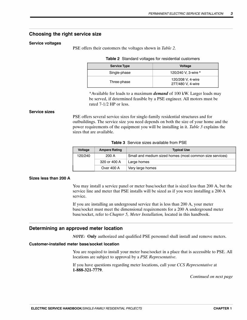
Service voltagesPSE offers their customers the voltages shown in Table 2.
Table 2 Standard voltages for residential customers
Service Type Voltage
Single-phase 120/240 V, 3-wire *
Three-phase120/208 V, 4-wire277/480 V, 4-wire
*Available for loads to a maximum demand of 100 kW. Larger loads maybe served, if determined feasible by a PSE engineer. All motors must berated 7-1/2 HP or less.
Service sizesPSE offers several service sizes for single-family residential structures and foroutbuildings. The service size you need depends on both the size of your home and thepower requirements of the equipment you will be installing in it. Table 3 explains thesizes that are available.
Table 3 Service sizes available from PSE
Voltage Ampere Rating Typical Use
120/240 200 A Small and medium sized homes (most common size services)
320 or 400 A Large homes
Over 400 A Very large homes
Sizes less than 200 A
You may install a service panel or meter base/socket that is sized less than 200 A, but theservice line and meter that PSE installs will be sized as if you were installing a 200 Aservice.
If you are installing an underground service that is less than 200 A, your meterbase/socket must meet the dimensional requirements for a 200 A underground meterbase/socket, refer to Chapter 5, Meter Installation, located in this handbook.
Determining an approved meter location
NOTE: Only authorized and qualified PSE personnel shall install and remove meters.
Customer-installed meter base/socket location
You are required to install your meter base/socket in a place that is accessible to PSE. Alllocations are subject to approval by a PSE Representative.
If you have questions regarding meter locations, call your CCS Representative at1-888-321-7779.
Continued on next page
PERMANENT ELECTRIC SERVICE INSTALLATION4
ELECTRIC SERVICE HANDBOOK/SINGLE‐FAMILY RESIDENTIAL PROJECTSCHAPTER 1
Meter base/sockets, including current transformer (CT) enclosures, must be located:
� Outside.
� On the front 1/3 of your home closest to normal public access.
� In an area that is not subject to being fenced-in (patios, decks, porches, breezewaysand backyards are bad locations).
� On a structure that is owned by you.
These approved locations allow us to:
� Read your meter in a cost-effective manner.
� Maintain your meter efficiently.
� Disconnect your service if there is a fire.
NOTE: Refer to Gas and Electric Underground Service Installation Requirementshandout for more information.
Know what’s below: Call 811 before you dig
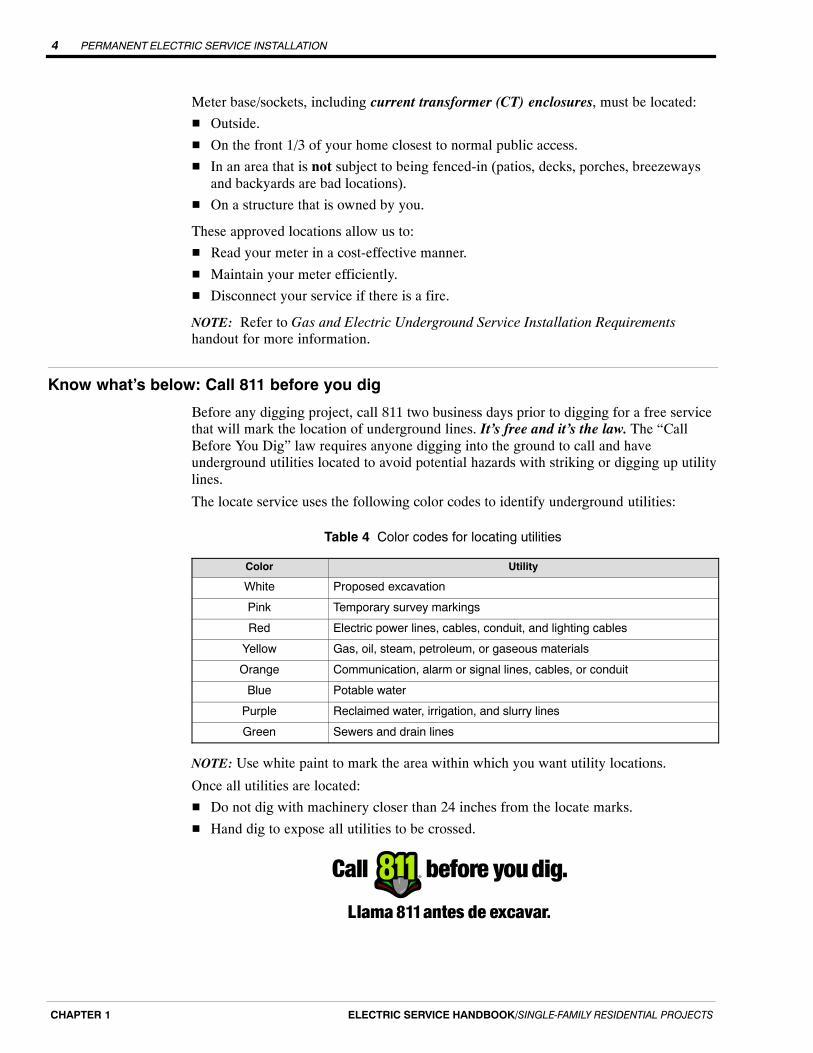
Before any digging project, call 811 two business days prior to digging for a free servicethat will mark the location of underground lines. It’s free and it’s the law. The “CallBefore You Dig” law requires anyone digging into the ground to call and haveunderground utilities located to avoid potential hazards with striking or digging up utilitylines.
The locate service uses the following color codes to identify underground utilities:
Table 4 Color codes for locating utilities
Color Utility
White Proposed excavation
Pink Temporary survey markings
Red Electric power lines, cables, conduit, and lighting cables
Yellow Gas, oil, steam, petroleum, or gaseous materials
Orange Communication, alarm or signal lines, cables, or conduit
Blue Potable water
Purple Reclaimed water, irrigation, and slurry lines
Green Sewers and drain lines
NOTE: Use white paint to mark the area within which you want utility locations.
Once all utilities are located:
� Do not dig with machinery closer than 24 inches from the locate marks.
� Hand dig to expose all utilities to be crossed.
PERMANENT ELECTRIC SERVICE INSTALLATION 5
ELECTRIC SERVICE HANDBOOK/SINGLE‐FAMILY RESIDENTIAL PROJECTS CHAPTER 1
Coordinating utility trenching and construction
New construction typically involves the installation of telephone cables, cable televisioncables, and natural gas lines; as well as electric power cables.
It is the responsibility of you and your builder to notify each utility about yourintended electric service installation as well as all other utilities providing service to yournew structure.
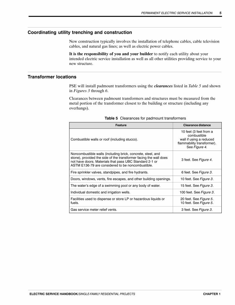
Transformer locations
PSE will install padmount transformers using the clearances listed in Table 5 and shownin Figures 3 through 6.
Clearances between padmount transformers and structures must be measured from themetal portion of the transformer closest to the building or structure (including anyoverhangs).
Table 5 Clearances for padmount transformers
Feature Clearance distance
Combustible walls or roof (including stucco).
10 feet (3 feet from acombustible
wall if using a reducedflammability transformer).
See Figure 4.
Noncombustible walls (including brick, concrete, steel, andstone), provided the side of the transformer facing the wall doesnot have doors. Materials that pass UBC Standard 2-1 orASTM E136-79 are considered to be noncombustible.
3 feet. See Figure 4.
Fire sprinkler valves, standpipes, and fire hydrants. 6 feet. See Figure 3.
Doors, windows, vents, fire escapes, and other building openings. 10 feet. See Figure 3.
The water’s edge of a swimming pool or any body of water. 15 feet. See Figure 3.
Individual domestic and irrigation wells. 100 feet. See Figure 3.
Facilities used to dispense or store LP or hazardous liquids orfuels.
20 feet. See Figure 5.10 feet. See Figure 5.
Gas service meter relief vents. 3 feet. See Figure 3.
PERMANENT ELECTRIC SERVICE INSTALLATION6
ELECTRIC SERVICE HANDBOOK/SINGLE‐FAMILY RESIDENTIAL PROJECTSCHAPTER 1
ÑÑÑÑÑÑÑÑÑÑÑÑÑÑÑÑÑÑÑÑÑÑÑÑÑÑÑÑÑÑÑÑÑÑÑÑÑÑÑÑÑÑÑÑÑÑÑÑÑÑÑÑÑÑÑÑÑÑ
Door, Window, Vent, orOther Opening
Sprinkler Valve,Standpipe, orHydrant
6�
10�
10�
Transformer
Fire Escape
3�FuelTank
GasMeterReliefVent
20�
ÑÑÑÑÑÑÑÑÑÑÑÑÑÑÑÑÑÑÑÑÑÑÑÑÑÑÑÑÑÑÑÑ
ÑÑÑÑÑÑÑÑÑÑ
100�Well Head
Pools or bodiesof water
15�
Transformer
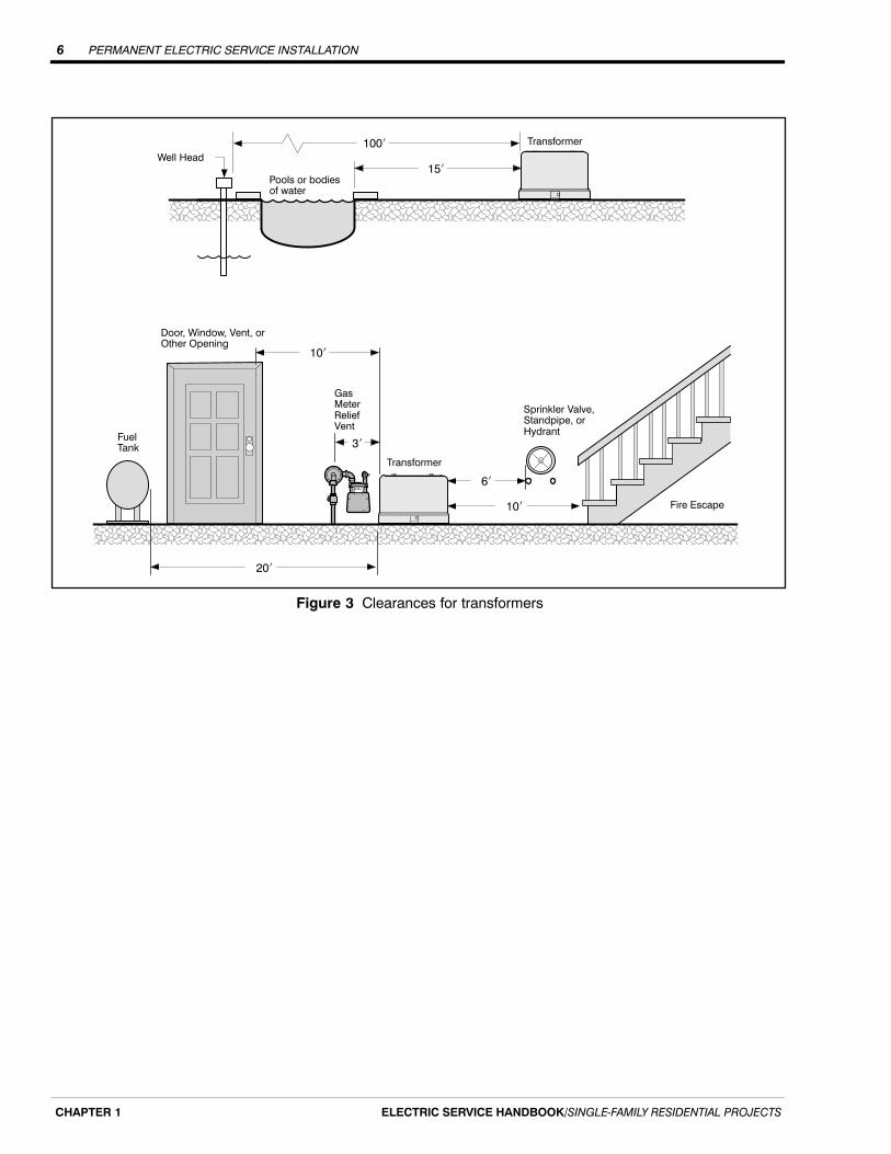
Figure 3 Clearances for transformers
PERMANENT ELECTRIC SERVICE INSTALLATION 7
ELECTRIC SERVICE HANDBOOK/SINGLE‐FAMILY RESIDENTIAL PROJECTS CHAPTER 1
ÉÉÉÉÉÉÉÉÉÉÉÉÉÉÉÉÉÉÉÉÉÉÉÉÉÉÉÉÉÉÉÉÉÉÉÉÉÉÉÉÉÉÉÉÉÉÉÉÉÉÉÉÉÉÉÉÉÉÉÉ
10�
10�
10�
Co
mb
ustib
le b
uild
ing
walls
an
d r
oo
f.
ApprovedTransformerArea
3�
3�
Co
mb
ustib
le b
uild
ing
walls
an
d r
oo
f.
10�
ÉÉÉÉÉÉÉÉÉÉÉÉÉÉÉÉÉÉÉÉÉÉÉÉÉÉÉÉÉÉÉÉÉÉÉÉÉÉÉÉÉÉÉÉÉÉÉÉÉÉÉÉÉÉÉÉÉÉÉÉÉÉÉÉÉÉÉÉÉÉÉÉÉÉÉÉÉÉÉÉÉÉÉÉÉÉÉÉÉÉÉÉÉÉÉÉÉÉÉÉÉÉÉÉÉÉÉÉ
ApprovedTransformerArea
ÉÉÉÉÉÉÉÉÉÉÉÉÉÉÉÉÉÉÉÉÉÉÉÉÉÉÉÉÉÉÉÉÉÉÉÉÉÉÉÉÉÉÉÉÉÉÉÉÉÉÉÉÉÉÉÉÉÉÉÉÉÉÉÉÉÉÉÉÉÉÉÉÉÉÉÉÉÉÉÉÉÉÉÉÉÉÉÉÉÉÉÉÉÉÉÉÉÉÉÉÉÉÉÉ
3�
No
nco
mb
ustib
le b
uild
ing
walls
ApprovedTransformerArea
Combustibleroof or soffit
10�
10�
ÉÉÉÉÉÉÉÉÉÉÉÉÉÉÉÉÉÉÉÉÉÉÉÉÉÉÉÉÉÉÉÉÉÉÉÉÉÉÉÉÉÉÉÉÉÉÉÉÉÉÉÉÉÉÉÉÉÉÉÉÉÉÉÉÉÉÉÉÉÉÉÉÉÉÉÉÉÉ
3�
3�3�
No
nco
mb
ustib
le b
uild
ing
walls
ApprovedTransformerArea
Noncombustibleroof and soffit
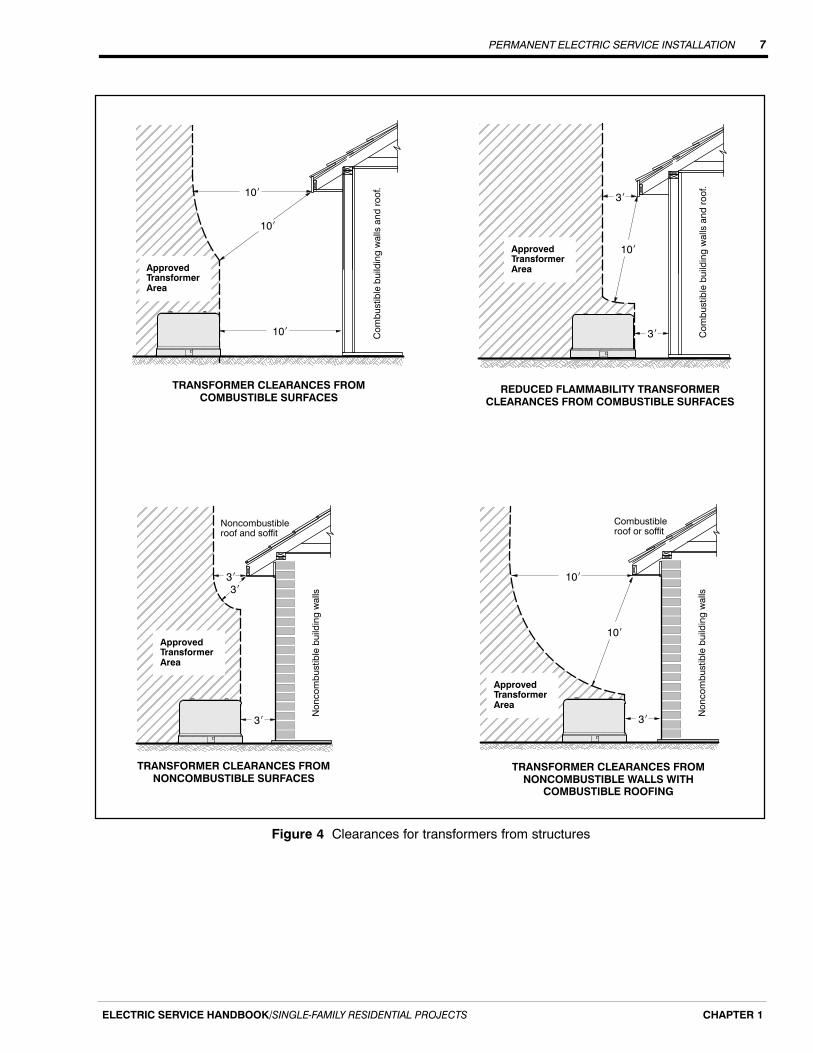
TRANSFORMER CLEARANCES FROMCOMBUSTIBLE SURFACES
REDUCED FLAMMABILITY TRANSFORMERCLEARANCES FROM COMBUSTIBLE SURFACES
TRANSFORMER CLEARANCES FROMNONCOMBUSTIBLE SURFACES
TRANSFORMER CLEARANCES FROMNONCOMBUSTIBLE WALLS WITH
COMBUSTIBLE ROOFING
Figure 4 Clearances for transformers from structures

PERMANENT ELECTRIC SERVICE INSTALLATION8
ELECTRIC SERVICE HANDBOOK/SINGLE‐FAMILY RESIDENTIAL PROJECTSCHAPTER 1
ÉÉÉÉÉÉÉÉÉÉÉÉÉÉÉÉ
20� Min
LP Tank
Oil‐Filled ElectricalEquipment(Pad or Pole Mounted)
6�Min
LP Tank
Oil‐FilledElectricalEquipment(Pad or PoleMounted)10� Min
Dike of adequate height tocontain oil and not allow itto flow towards the LP tank.
Top View
Figure 5 Minimum clearances from oil-filled equipment to LP, hazardous liquid, or fuel tanks
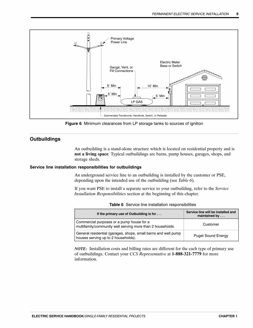
Liquefied propane tanks: clearances from ignition source
If there are liquefied propane (LP), hazardous liquid, or fuel tanks on your property, thefollowing minimum clearances apply from PSE’s padmounted transformer or the ignitionsource (see Figures 5 and 6).
� All LP tanks must be at least 6 feet from a vertical plane extending down from anoverhead primary voltage line.
� Consumer storage LP tanks must be at least 5 feet from any source of ignition, suchas electric meter bases, submersible transformers, secondary handholes or pedestals,or padmount switches.
� The fill connection, gauge connection, or vent on the LP tank must be at least 10 feetfrom any source of ignition.
PERMANENT ELECTRIC SERVICE INSTALLATION 9
ELECTRIC SERVICE HANDBOOK/SINGLE‐FAMILY RESIDENTIAL PROJECTS CHAPTER 1
6� Min 10� Min
LP GAS
5� Min
Gauge, Vent, orFill Connections
Primary VoltagePower Line
Electric MeterBase or Switch
5� Min
ÑÑÑÑÑÑÑÑÑÑÑÑÑÑÑÑÑÑÑÑÑÑÑÑÑÑÑÑÑÑÑÑÑÑÑÑÑÑÑÑÑÑÑÑÑÑÑÑÑÑÑÑ
Submersible Transformer, Handhole, Switch, or Pedestal
Figure 6 Minimum clearances from LP storage tanks to sources of ignition
Outbuildings
An outbuilding is a stand-alone structure which is located on residential property and isnot a living space. Typical outbuildings are barns, pump houses, garages, shops, andstorage sheds.
Service line installation responsibilities for outbuildings
An underground service line to an outbuilding is installed by the customer or PSE,depending upon the intended use of the outbuilding (see Table 6).
If you want PSE to install a separate service to your outbuilding, refer to the ServiceInstallation Responsibilities section at the beginning of this chapter.
Table 6 Service line installation responsibilities
If the primary use of Outbuilding is for . . . Service line will be installed andmaintained by . . .
Commercial purposes or a pump house for amultifamily/community well serving more than 2 households. Customer
General residential (garages, shops, small barns and well pumphouses serving up to 2 households). Puget Sound Energy
NOTE: Installation costs and billing rates are different for the each type of primary useof outbuildings. Contact your CCS Representative at 1-888-321-7779 for moreinformation.

PERMANENT ELECTRIC SERVICE INSTALLATION10
ELECTRIC SERVICE HANDBOOK/SINGLE‐FAMILY RESIDENTIAL PROJECTSCHAPTER 1
Cost for service
Charges vary depending on the location of existing electrical facilities, the type of serviceyou are requesting, and the distance to run service from our facilities to your home.Contact CCS at 1-888-321-7779 to determine the cost for service.
Power quality, voltage flicker
In your Application for Service (Form 1378, 4414, or 4409), you must provide PSE withthe locked rotor starting currents for the largest single-phase and three-phase motors.After we determine the size of transformer required to serve the new load of the facility,we will calculate the percent voltage flicker (from the motor’s starting current) at thepoint of service and provide that number to you.
If this voltage dip exceeds PSE’s limits based on facility type, the transformer size mustbe increased to compensate for this. You will be responsible for the difference in cost ofthe larger transformer, or you will need to install sufficient controls to bring flicker backwithin PSE’s limits.
NOTE: We will size PSE’s facilities to provide a level of voltage flicker that is normallyacceptable to customers. If you need to be served with a higher quality of service, contactyour CCS Representative.

PERMANENT UNDERGROUND SERVICE 11
ELECTRIC SERVICE HANDBOOK/SINGLE‐FAMILY RESIDENTIAL PROJECTS CHAPTER 2
Chapter 2
Permanent Underground Service
Steps to a successful underground service installation
The following list details the key steps in the installation of your underground serviceresulting in PSE’s installation of your underground service line and meter (see Figure 7).
� Find out where your service line will originate by contacting Customer ConstructionServices (CCS) at 1-888-321-7779.
� Obtain an electrical work permit.
� Determine an acceptable location for your meter base/socket.
� Order underground utility locate service by contacting the 811 “Call Before You Dig”hotline two business days before digging.
� Dig a trench and provide proper conduit between your meter location and the serviceline origination (transformer, handhole, pole, or stubout).
− Provide 4-foot-square work pits at poles, stubouts, handholes, and meter serviceentrance.
− Provide conduit for electrical service lines that are less than 100 feet and a 3/8-inch pull rope if over 60 feet.
� Install your meter base/socket service entrance equipment.
� Obtain a city or state electrical inspection and approval of your installation.
� Call CCS at 1-888-321-7779 to have your service installed and energized.
ÑÑÑÑÑÑÑÑÑÑÑÑÑÑÑÑÑÑÑÑÑÑÑÑÑÑÑÑÑÑÑÑÑÑÑÑÑÑÑÑÑÑÑÑÑÑÑÑÑÑÑÑ
24� Min depth of cover48� Max. depth of trench
SecondaryHandhole
Underground Service Line
Meter Riser
Pole
Figure 7 Typical underground service from overhead power facilities

PERMANENT UNDERGROUND SERVICE12
ELECTRIC SERVICE HANDBOOK/SINGLE‐FAMILY RESIDENTIAL PROJECTSCHAPTER 2
Selecting a meter base/socket location
When choosing your meter base/socket location, be sure to consider the types of terrainwhere your service line will be buried. Since PSE is responsible for repairing yourservice line if it fails, the path you select is subject to being dug up. Therefore, werecommend that the service line route be accessible for repairs and excavation.
NOTE: Refer to Chapter 1, Determining an approved meter location section,Customer-installed meter base/socket location subsection.
Multiple metered services
If a residential class customer installs a bus gutter or meter-pack enclosure to set two meters (one meter for the house, the other for the shop, barn, garage, etc.) on asingle piece of property being billed to the same individual, PSE will run a singleservice line at the customer’s request. However, the single line must accommodate thekW load and limit the voltage drop and voltage flicker to within PSE’s standards.
NOTE: PSE will not run a single service line to a bus gutter or meter-pack that servesmultiple residential class customers residing on differing properties with separate legalownership.
Service line trenches
This section refers to the illustrations found in the Gas and Electric Underground ServiceInstallation Requirements handout, located in the back pocket of this handbook.
Trench and backfill requirements
PSE will allow customer-owned facilities within the service line trench, if the followingminimum horizontal clearances from PSE facilities are maintained:
� 18 inches minimum for customer-owned tight-line sewer (not tile), storm drain lines,roof drain lines, natural gas line, propane gas line, fuel oil line, and water mains up to6 inches.
� 12 inches minimum for water services, irrigation pipes, lighting, security and electricsupply circuits, closed-system roof drains/storm drains (not French drains), andculverts.
NOTE: The Gas and Electric Underground Service Installation Requirements handoutillustrates the service trench requirements in detail.
Customer-installed service line conduit
If your service line will be crossing under any permanent structure (driveways,sidewalks, decks, patios, rockeries, retaining walls, or through your backyard), you arerequired to provide and install conduit under those obstructions.
You are required to provide an electrical service line conduit for services 100 feet long orless. However, PSE recommends the use of conduit for all services.
PERMANENT UNDERGROUND SERVICE 13
ELECTRIC SERVICE HANDBOOK/SINGLE‐FAMILY RESIDENTIAL PROJECTS CHAPTER 2
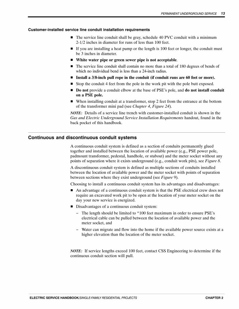
Customer-installed service line conduit installation requirements
� The service line conduit shall be gray, schedule 40 PVC conduit with a minimum2-1/2 inches in diameter for runs of less than 100 feet.
� If you are installing a heat pump or the length is 100 feet or longer, the conduit mustbe 3 inches in diameter.
� White water pipe or green sewer pipe is not acceptable.
� The service line conduit shall contain no more than a total of 180 degrees of bends ofwhich no individual bend is less than a 24-inch radius.
� Install a 3/8-inch pull rope in the conduit (if conduit runs are 60 feet or more).
� Stop the conduit 4 feet from the pole in the work pit with the pole butt exposed.
� Do not provide a conduit elbow at the base of PSE’s pole, and do not install conduiton a PSE pole.
� When installing conduit at a transformer, stop 2 feet from the entrance at the bottomof the transformer mini pad (see Chapter 4, Figure 24).
NOTE: Details of a service line trench with customer-installed conduit is shown in theGas and Electric Underground Service Installation Requirements handout, found in theback pocket of this handbook.
Continuous and discontinuous conduit systems
A continuous conduit system is defined as a section of conduits permanently gluedtogether and installed between the location of available power (e.g., PSE power pole,padmount transformer, pedestal, handhole, or stubout) and the meter socket without anypoints of separation where it exists underground (e.g., conduit work pits), see Figure 8.
A discontinuous conduit system is defined as multiple sections of conduits installedbetween the location of available power and the meter socket with points of separationbetween sections where they exist underground (see Figure 9).
Choosing to install a continuous conduit system has its advantages and disadvantages:
� An advantage of a continuous conduit system is that the PSE electrical crew does notrequire an excavated work pit to be open at the location of your meter socket on theday your new service is energized.
� Disadvantages of a continuous conduit system:
− The length should be limited to *100 feet maximum in order to ensure PSE’selectrical cable can be pulled between the location of available power and themeter socket, and
− Water can migrate and flow into the home if the available power source exists at ahigher elevation than the location of the meter socket.
NOTE: If service lengths exceed 100 feet, contact CSS Engineering to determine if thecontinuous conduit section will pull.

PERMANENT UNDERGROUND SERVICE14
ELECTRIC SERVICE HANDBOOK/SINGLE‐FAMILY RESIDENTIAL PROJECTSCHAPTER 2
ÔÔÔÔÔÔÔÔÔÔÔÔ
ÑÑÑÑÑÑÑÑÑÑÑÑÑÑÑÑÑÑÑÑÑÑÑÑÑÑÑÑÑÑÑÑÑÑÑÑÑÑÑÑÑÑÑÑÑÑÑÑÑÑÑÑÑÑÑÑÑÑÑÑÑÑÑÑÑÑÑÑÑÑÑÑÑÑÑÑÑÑÑÑÑÑÑÑÑÑÑÑÑÑÑÑÑÑÑÑÑÑÑÑÑÑÑÑÑÑÑÑÑÑÑÑÑÑÑÑÑÑÑÑÑÑÑÑÑÑÑÑÑÑÑÑÑÑÑÑÑÑÑÑÑÑÑÑÑÑÑÑÑÑÑÑÑÑÑÑÑÑÑÑÑÑÑÑÑÑÑÑÑÑÑÑÑÑÑÑÑÑÑÑÑÑÑÑÑÑÑÑÑÑÑÑÑÑÑÑÑÑÑÑÑÑÑÑÑÑÑÑÑÑÑÑÑÑÑÑÑÑÑÑÑÑÑÑÑÑÑÑÑÑÑÑÑÑÑÑÑÑÑÑÑÑÑÑÑÑÑÑ
ÎÎÎÎÎÎÎÎÎÎÎÎÎÎ
ÖÖÖÖÖÖÖÖÖÖÖÖÖÖÖÖÖÖÖÖ
ÑÑÑÑÑÑÑÑÑÑÑÑÑÑÑÑÑÑÑÑ
ÑÑ
ÔÔÔÔÔÔÔÔ
ÍÍÍÍÍÍÍÍÍÍÍÍÍÍÍÍÍÍÍÍÍÍÍÍÍÍÍÍÍÍÍÍÍÍ
Meter Socket(Surface or Flush Mounted)
Continuous conduit between availablesource of power and service entrance(Meter socket)
PSE Transformer(Or Pedestal, Handhole, Pole, or Stub‐out)
PSE Service Cable
ÑÑÑÑÑÑÑÑÑÑÑÑÑÑÑÑÑÑ
Excavated Dirt Pileand
Sand Bedding/Shading
24� Min
Figure 8 Example of continuous conduit in underground electric service
When to choose continuous conduit
Choose to install a continuous conduit system for your electrical service if:� Your electrical service length is 100 feet or less.� The sum total of the degrees of bends in the conduit run (including the bend required
at the bottom of the meter base riser) does not exceed 180�.� The elevation at the location of available power is less than the elevation of your
meter socket (i.e., your meter socket is uphill from the location of available power).
NOTE: By choosing to install a continuous conduit system, the customer assumesresponsibility for recognizing potential surface and sub-grade water flows that may createan entry of water into the customer’s electrical equipment. PSE is not responsible fordamage caused by water entering a customer’s meter base or equipment.

PERMANENT UNDERGROUND SERVICE 15
ELECTRIC SERVICE HANDBOOK/SINGLE‐FAMILY RESIDENTIAL PROJECTS CHAPTER 2
ÑÑÑÑÑÑÑÑÑÑÑÑÑÑÑ
ÔÔÔÔÔÔÔÔÔÔÔÔ
ÑÑÑÑÑÑÑÑÑÑÑÑÑÑÑÑÑÑÑÑÑÑÑÑÑÑÑÑÑÑÑÑÑÑÑÑÑÑÑÑÑÑÑÑÑÑÑÑÑÑÑÑÑÑÑÑÑÑÑÑÑÑÑÑÑÑÑÑÑÑÑÑÑÑÑÑÑÑÑÑÑÑÑÑÑÑÑÑÑÑÑÑÑÑÑÑÑÑÑÑÑÑÑÑÑÑÑÑÑÑÑÑÑÑÑÑÑÑÑÑÑÑÑÑÑÑÑÑÑÑÑÑÑÑÑÑÑÑÑÑÑÑÑÑÑÑÑÑÑÑÑÑÑÑÑÑÑÑÑÑÑÑÑÑÑÑÑÑÑÑÑÑÑÑÑÑÑÑÑÑÑÑÑÑÑÑÑÑÑÑÑÑÑÑÑÑÑÑÑÑÑÑÑÑÑÑÑÑÑÑ
ÎÎÎÎÎÎÎÎÎÎÎÎÎÎ
ÖÖÖÖÖÖÖÖÖÖÖÖÖÖÖÖÖÖÖÖ
ÑÑÑÑÑÑÑÑÑÑÑÑÑÑÑÑ
ÑÑÑÑ
ÔÔÔÔÔÔÔÔ
Meter Socket(Surface or Flush Mounted)
One or multiple sections of discontinuousconduit between available source of powerand service entrance. (Meter Socket)
PSE Transformer(Or Pedestal, Handhole, Pole, or Stub‐out)
PSE Service Cable
ÑÑÑÑÑÑÑÑÑÑÑÑÑÑÑÑÑÑÑÑÑÑÑÑ
ÑÑÑÑÑÑÑÑÑÑÑÑÑÑÑÑ
ÑÑÑÑÑÑÑÑÑÑÑÑÑÑÑÑÑÑÑÑÑÑÑÑÑÑÑÑÑÑÑÑÑÑÑÑÑÑÑÑÑÑÑÑÑÑÑÑÑÑÑÑÑÑÑÑÑÑÑÑÑÑÑÑÑÑÑÑÑÑ
ÍÍÍÍÍÍÍÍÍÍÍÍÍÍÍÍÍÍÍÍÍÍÍÍÍÍÍÍÍÍÍÍÍÍÍÍÍÍ
Excavated Dirt Pileand
Sand Bedding/Shading
24� Min 24� Min
Figure 9 Example of discontinuous conduit in underground electric service
When to choose discontinuous conduit
Choose to install a discontinuous conduit system for your electrical service if:� Your electrical service length is 101 feet or longer.� The sum total of the degrees of bends in the conduit run (including the bend required
at the bottom of the meter base riser) exceeds 180� requiring additional work pits forcable pulling.
� The elevation at the location of available power is greater than the elevation of yourmeter socket (i.e., your meter socket is downhill from the location of availablepower).
A table for selecting the required conduit size in a continuous conduit system is providedin the Gas and Electric Underground Service Installation Requirements handout found inthe back pocket of this handbook.
Contact CCS at 1-888-321-7779 if you have questions on whether to install continuousor discontinuous conduit for your underground electric service.
PERMANENT UNDERGROUND SERVICE16
ELECTRIC SERVICE HANDBOOK/SINGLE‐FAMILY RESIDENTIAL PROJECTSCHAPTER 2
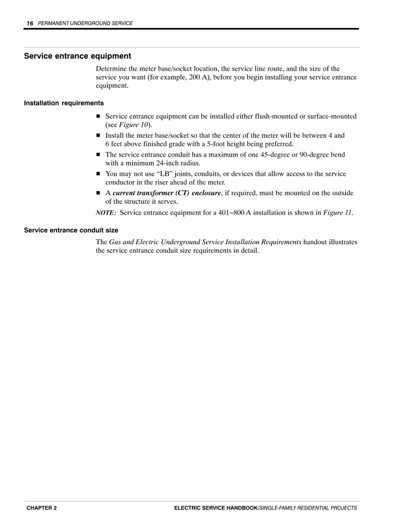
Service entrance equipment
Determine the meter base/socket location, the service line route, and the size of theservice you want (for example, 200 A), before you begin installing your service entranceequipment.
Installation requirements
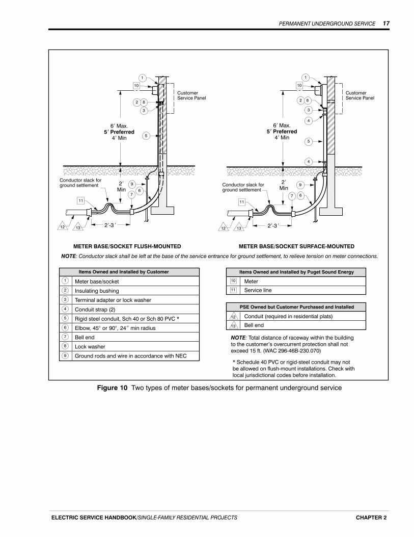
� Service entrance equipment can be installed either flush-mounted or surface-mounted(see Figure 10).
� Install the meter base/socket so that the center of the meter will be between 4 and6 feet above finished grade with a 5-foot height being preferred.
� The service entrance conduit has a maximum of one 45-degree or 90-degree bendwith a minimum 24-inch radius.
� You may not use “LB” joints, conduits, or devices that allow access to the serviceconductor in the riser ahead of the meter.
� A current transformer (CT) enclosure, if required, must be mounted on the outsideof the structure it serves.
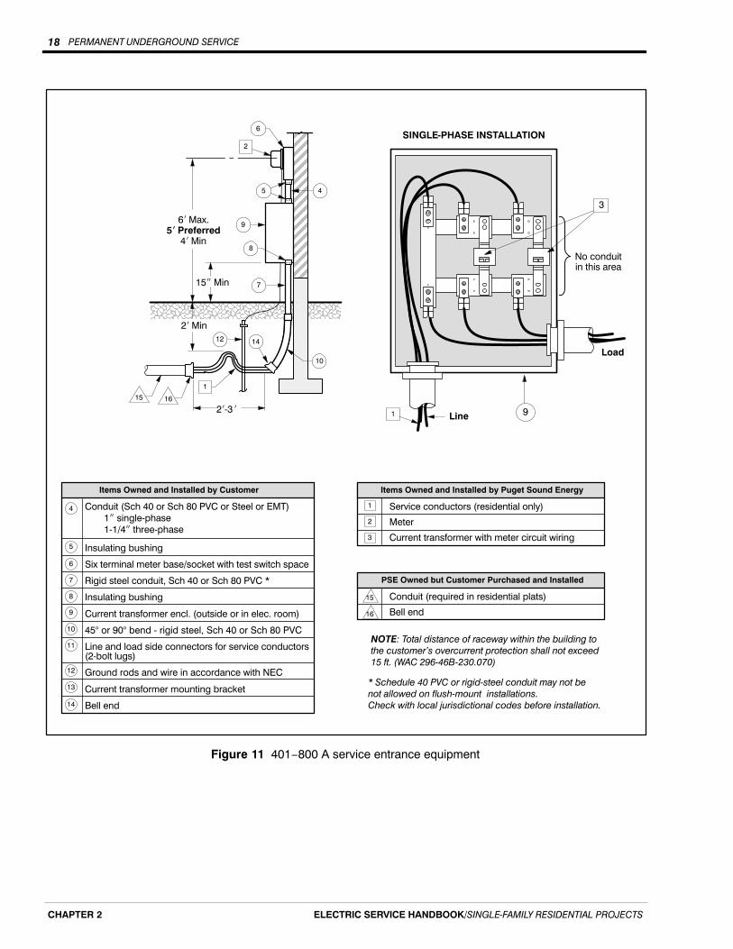
NOTE: Service entrance equipment for a 401−800 A installation is shown in Figure 11.
Service entrance conduit size
The Gas and Electric Underground Service Installation Requirements handout illustratesthe service entrance conduit size requirements in detail.
PERMANENT UNDERGROUND SERVICE 17
ELECTRIC SERVICE HANDBOOK/SINGLE‐FAMILY RESIDENTIAL PROJECTS CHAPTER 2
Meter base/socket
Insulating bushing
Terminal adapter or lock washer
Conduit strap (2)
Rigid steel conduit, Sch 40 or Sch 80 PVC *
Elbow, 45° or 90°, 24� min radius
Bell end
Lock washer
Ground rods and wire in accordance with NEC
Meter
Service line
NOTE: Total distance of raceway within the building
to the customer's overcurrent protection shall not
exceed 15 ft. (WAC 296‐46B‐230.070)
* Schedule 40 PVC or rigid‐steel conduit may not
be allowed on flush‐mount installations. Check with
local jurisdictional codes before installation.
11
Items Owned and Installed by Puget Sound EnergyItems Owned and Installed by Customer
1
Conduit (required in residential plats)
Bell end
12
PSE Owned but Customer Purchased and Installed
13
10
2
3
4
5
6
7
8
9
ÑÑÑÑÑÑÑÑÑÑÑÑÑÑÑÑÑÑÑÑÑÑÑÑÑÑ ÑÑÑÑÑÑÑÑÑÑÑÑÑÑ
ÍÍÍÍÍÍÍÍÍÍÍÍÍÍÍÍ
CustomerService Panel
2�Min
ÍÍÍÍÍÍÍÍ
CustomerService Panel
Conductor slack forground settlement
METER BASE/SOCKET FLUSH‐MOUNTED METER BASE/SOCKET SURFACE‐MOUNTED
10
6� Max.5� Preferred
4� Min
6� Max.5� Preferred
4� Min
NOTE: Conductor slack shall be left at the base of the service entrance for ground settlement, to relieve tension on meter connections.
4
2
1
9
6
82
3
2�Min
12 132�‐�3 � 2�‐�3 �
11
7
8
5
4
3
5
10
1
12 13
11
9
67
Conductor slack forground settlement
Figure 10 Two types of meter bases/sockets for permanent underground service
PERMANENT UNDERGROUND SERVICE18
ELECTRIC SERVICE HANDBOOK/SINGLE‐FAMILY RESIDENTIAL PROJECTSCHAPTER 2
ÑÑÑÑÑÑÑÑÑÑÑÑÑÑÑÑÑÑÑÑÑÑ
Service conductors (residential only)
Meter
Current transformer with meter circuit wiring
NOTE: Total distance of raceway within the building to
the customer's overcurrent protection shall not exceed
15 ft. (WAC 296‐46B‐230.070)
* Schedule 40 PVC or rigid‐steel conduit may not be
not allowed on flush‐mount installations.
Check with local jurisdictional codes before installation.
ÍÍÍÍÍÍÍÍÍÍÍÍÍÍÍÍÍÍ
2
Items Owned and Installed by Puget Sound Energy
6� Max.5� Preferred
4� Min
Conduit (required in residential plats)
Bell end
15
PSE Owned but Customer Purchased and Installed
16
1
7
2
4
9
6
5
8
15� Min
2�‐�3 �
15 16
1
14
10
12
2� Min
3
Conduit (Sch 40 or Sch 80 PVC or Steel or EMT)
��1� single‐phase
��1‐1/4� three‐phase
Insulating bushing
Six terminal meter base/socket with test switch space
Rigid steel conduit, Sch 40 or Sch 80 PVC *
Insulating bushing
Current transformer encl. (outside or in elec. room)
45° or 90° bend ‐ rigid steel, Sch 40 or Sch 80 PVC
Line and load side connectors for service conductors(2‐bolt lugs)
Ground rods and wire in accordance with NEC
Current transformer mounting bracket
Bell end
Items Owned and Installed by Customer
4
5
6
7
8
9
10
11
12
13
14
Load
No conduitin this area
Line
SINGLE‐PHASE INSTALLATION
1
3
9
Figure 11 401−800 A service entrance equipment

PERMANENT UNDERGROUND SERVICE 19
ELECTRIC SERVICE HANDBOOK/SINGLE‐FAMILY RESIDENTIAL PROJECTS CHAPTER 2
Permanent underground service for manufactured homes, 0−200 A
Service equipment installation
If you are installing an underground service to your manufactured home, your serviceequipment can be installed one of two ways:
� On a customer-owned pedestal or meter post (see Figure 12).
� On the manufactured home, if both of the following conditions are met:
− The manufacturer installed the service equipment at the time your home was built.
− The service equipment meets the meter base/socket requirements listedbelow.
Meter base/socket requirements
Meter base/sockets installed on manufactured homes must:
� Be located on an outside wall of your home.
� Be located on the front one-third of your home closest to normal public access. Referto Meter Locations and Clearances on Page 1 of the Gas and Electric UndergroundService Installation Requirements handout for more information.
� Be between 4 and 6 feet above finished grade.
� Meet PSE’s service entrance conduit size requirements.
� Not be in a walkway or breezeway.
� Not be in an area that is subject to being fenced.
NOTE: Meter bases/sockets not installed on the manufactured home must meet therequirements of NEC 550.32(B).
PERMANENT UNDERGROUND SERVICE20
ELECTRIC SERVICE HANDBOOK/SINGLE‐FAMILY RESIDENTIAL PROJECTSCHAPTER 2
ÑÑÑÑÑÑÑÑÑÑÑÑÑÑÑÑÑÑÑÑÑÑÑÑ
6� x 6� x 8� min fully pressure‐treated post
Service entrance equipment
Service conduit as specified in Table 7
Ground wire, if required by the NEC
Ground rod, if required by the NEC
Service conductor to building/residence
Elbow, 45° or 90° bend, 24� min radius
36� x 36� x 3� min concrete stabilizer pad
Bell end
Items Owned and Installed by Customer
Meter
PSE Service line12
Items Owned and Installed by Puget Sound Energy
Conduit (required in residential plats)
Bell end
13
PSE Owned but Customer Purchased and Installed
14
111
2
3
4
5
6
7
8
9
10
Factory‐built metal meter pedestal(manufactured homes only)
ÑÑÑÑÑÑÑÑÑÑÑÑÑÑÑÑÑÑÑÑÑÑÑÑÑÑÑÑ
Conduit to be rigidlyfastened to support.
6� Max.3� Min
36� Min
24� Min
24� Min
7
4
METER POST
3
Line
Load
1
11
2
5
12
13
14
2�‐�3 �
10
Customer's conductor to mobilehome. Install according to NEC.
3� Min
24� Min
Line
Load
WeatherproofPanel
9
7
3
METER PEDESTALManufactured homes only
6
12
5
4
13
14
2�‐�3 �
10
8
11
Customer's conductor to mobilehome. Install according to NEC.
6
Figure 12 Permanent underground service for manufactured homes, 0−200 A
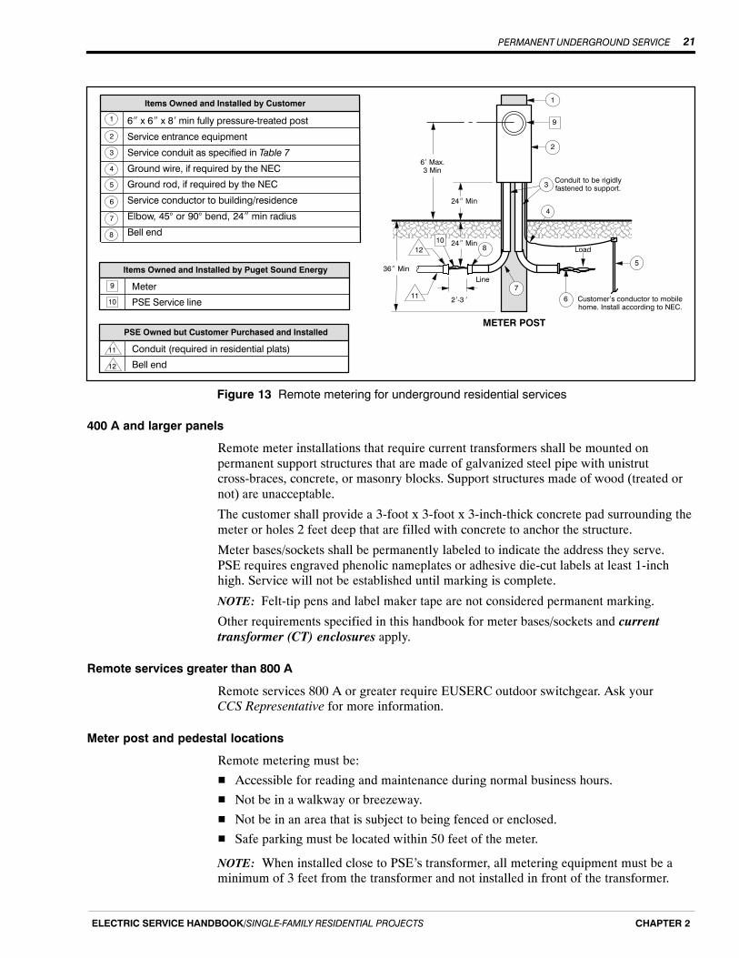
Remote metering (meter loop) for underground residential services
What is remote metering?
Normally, a meter base/socket and associated devices (current transformers, etc.) areattached to a permanent fixed structure that contains the load being served (such as ahouse). If the metering equipment is not attached to the permanent structure, it is called“remote metering.” In this case, the conductors that run from the meter to your house areinstalled, owned, and maintained by you.
Requirements for residential remote metering, 200 A or less
Remote metering shall be mounted on a structure or meter post. It is your responsibilityto purchase, install, and maintain this equipment. The required metering cabinet andsupporting structure are shown in Figure 13.
PERMANENT UNDERGROUND SERVICE 21
ELECTRIC SERVICE HANDBOOK/SINGLE‐FAMILY RESIDENTIAL PROJECTS CHAPTER 2
6� x 6� x 8� min fully pressure‐treated post
Service entrance equipment
Service conduit as specified in Table 7
Ground wire, if required by the NEC
Ground rod, if required by the NEC
Service conductor to building/residence
Elbow, 45° or 90° bend, 24� min radius
Bell end
Items Owned and Installed by Customer
Meter
PSE Service line10
Items Owned and Installed by Puget Sound Energy
Conduit (required in residential plats)
Bell end
11
PSE Owned but Customer Purchased and Installed
12
9
1
2
3
4
5
6
7 ÑÑÑÑÑÑÑÑÑÑÑÑÑÑÑÑÑÑÑÑÑÑÑÑÑÑ
Conduit to be rigidlyfastened to support.
6� Max.3 Min
36� Min
24� Min
24� Min
7
4
METER POST
3
Line
Load
1
9
2
10
11
12
2�‐�3 �
8
Customer's conductor to mobilehome. Install according to NEC.
6
5
8
Figure 13 Remote metering for underground residential services
400 A and larger panels
Remote meter installations that require current transformers shall be mounted onpermanent support structures that are made of galvanized steel pipe with unistrutcross-braces, concrete, or masonry blocks. Support structures made of wood (treated ornot) are unacceptable.
The customer shall provide a 3-foot x 3-foot x 3-inch-thick concrete pad surrounding themeter or holes 2 feet deep that are filled with concrete to anchor the structure.
Meter bases/sockets shall be permanently labeled to indicate the address they serve. PSE requires engraved phenolic nameplates or adhesive die-cut labels at least 1-inchhigh. Service will not be established until marking is complete.
NOTE: Felt-tip pens and label maker tape are not considered permanent marking.
Other requirements specified in this handbook for meter bases/sockets and currenttransformer (CT) enclosures apply.
Remote services greater than 800 A
Remote services 800 A or greater require EUSERC outdoor switchgear. Ask your CCS Representative for more information.
Meter post and pedestal locations
Remote metering must be:
� Accessible for reading and maintenance during normal business hours.
� Not be in a walkway or breezeway.
� Not be in an area that is subject to being fenced or enclosed.
� Safe parking must be located within 50 feet of the meter.
NOTE: When installed close to PSE’s transformer, all metering equipment must be aminimum of 3 feet from the transformer and not installed in front of the transformer.

PERMANENT UNDERGROUND SERVICE22
ELECTRIC SERVICE HANDBOOK/SINGLE‐FAMILY RESIDENTIAL PROJECTSCHAPTER 2
PERMANENT OVERHEAD SERVICE 23
ELECTRIC SERVICE HANDBOOK/SINGLE‐FAMILY RESIDENTIAL PROJECTS CHAPTER 3
Chapter 3
Permanent Overhead Service
Steps to a successful overhead service installation
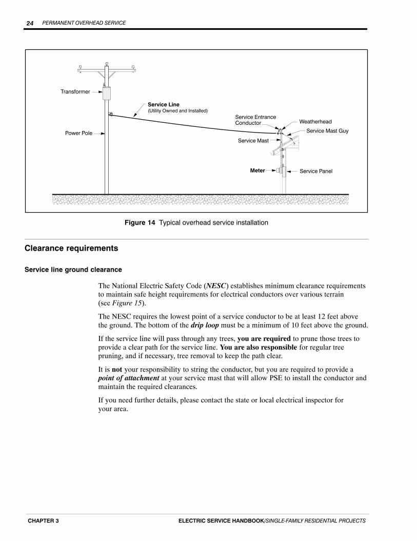
The following checklist will assist you in preparing for the installation of an overheadservice (see Figure 14). After you have completed these items, PSE can install theoverhead service line and meter.
� Check for any local ordinances/covenants that prevent you from obtaining anoverhead service.
� Obtain an electrical work permit.
� Complete Electric Service Application Single-Family Residential 100E (Form 4414).All forms can be downloaded at PSE.com.
� Supply site drawings and load information to your PSE Customer ConstructionServices (CCS) Representative.
� Call CCS to find out where your service line will originate.
� Determine an acceptable location for your meter base/socket.
� Provide a path clear of obstructions between PSE’s service pole and yourservice mast.
� Provide the location of any domestic or community water well on your property.
� Install the required service entrance equipment.
� Install the service entrance conductors (leave a minimum of 18 inches exposed at theweatherhead).
� Verify that the service mast height requirements have been met (see Figure 15).
� Provide payment for any preconstruction costs determined by CCS.
� Have the city or state inspect and approve your installation.
� Call CCS at 1-888-321-7779 to have your service installed and energized.
Selecting a meter base/socket location
After CCS determines which pole the service line will come from, you can determine thelocation of your meter base/socket.
Your meter base/socket should be located outside and on the front one-third of yourstructure closest to normal public access. Refer to the Gas and Electric UndergroundService Installation Requirements handout located in the back pocket of this handbook.
Consider the type of terrain the line will cross when choosing a meter base/socketlocation. PSE strongly suggests avoiding service line routes that cross a driveway.Service lines that cross driveways can be hit by vehicles, which can cause damage to theservice equipment and even to your home.
PERMANENT OVERHEAD SERVICE24
ELECTRIC SERVICE HANDBOOK/SINGLE‐FAMILY RESIDENTIAL PROJECTSCHAPTER 3
Service PanelMeter
Service Mast
Service EntranceConductor
Service Mast Guy
Weatherhead
Transformer
Power Pole
Service Line(Utility Owned and Installed)
ÁÁÁÁÁÁÁÁÁ
ÁÁÁÁ
ÌÌÌÌÌÌÌÌÌÌÌÌÌÌÌÌÌÌÌÌÌÌÌÌÌÌÌÌÌÌÌÌÌÌÌÌÌÌÌÌÌÌÌÌÌÌÌÌÌÌÌÌÌÌÌÌÌÌ
Figure 14 Typical overhead service installation
Clearance requirements
Service line ground clearance
The National Electric Safety Code (NESC) establishes minimum clearance requirementsto maintain safe height requirements for electrical conductors over various terrain(see Figure 15).
The NESC requires the lowest point of a service conductor to be at least 12 feet abovethe ground. The bottom of the drip loop must be a minimum of 10 feet above the ground.
If the service line will pass through any trees, you are required to prune those trees toprovide a clear path for the service line. You are also responsible for regular treepruning, and if necessary, tree removal to keep the path clear.
It is not your responsibility to string the conductor, but you are required to provide apoint of attachment at your service mast that will allow PSE to install the conductor andmaintain the required clearances.
If you need further details, please contact the state or local electrical inspector foryour area.
PERMANENT OVERHEAD SERVICE 25
ELECTRIC SERVICE HANDBOOK/SINGLE‐FAMILY RESIDENTIAL PROJECTS CHAPTER 3
17‐1/2�
26�
Service MastConnection Point
ÁÁÁÁÁÁÁ
12�
Service Line(Utility Owned)
ÌÌÌÌÌÌÌÌÌÌÌÌÌÌÌÌÌÌÌÌÌÌÌÌÌÌÌÌÌÌÌÌÌÌÌÌÌÌÌÌÌÌÌÌÌÌÌÌÌÌÌÌÌÌ
13�
State Highways Streets, Alleys, CountyRoads, and Driveways
Residential Property
Figure 15 Minimum overhead service line vertical clearances from ground level
Minimum clearances from structures, building openings, and gas meters
� A minimum clearance of 3 feet is required between electric service lines andwindows, doors, porches, fire escapes, or similar openings.
� A minimum horizontal clearance of 3 feet is required between electric serviceequipment and natural gas meter pressure relief vent (see Figure 16).
� Service lines passing over the roof of another structure (but not attached to thatstructure) must maintain the minimum clearances (see Figure 16).
� Service lines passing over a deck must maintain a minimum clearance of 11 feet(see Figure 16).
ÁÁÁÁÁÁÁ
Gas Meter
3�Min
ElectricMeter
3‐1/2� Min
11� Min
11� Min
Service Line(Utility Owned)
DeckÌÌÌÌÌÌÌÌÌÌÌÌÌÌÌÌÌÌÌÌÌÌÌÌÌÌÌÌÌÌÌÌÌÌÌÌÌÌÌÌÌÌÌÌÌÌÌÌÌÌÌÌÌÌÌÌÌÌ
Roofs withoutPermanent Access
Roofs withPermanent Access
Figure 16 Minimum clearances over other structures
PERMANENT OVERHEAD SERVICE26
ELECTRIC SERVICE HANDBOOK/SINGLE‐FAMILY RESIDENTIAL PROJECTSCHAPTER 3
Intermediate service pole
When the length of an overhead service line exceeds 125 feet or the clearances shown inFigure 16 cannot be achieved, an intermediate service pole may be required to maintainsafe ground clearance (see Figure 17) for the wire and to relieve excessive tension at theservice mast.
This intermediate service pole is set and owned by PSE and the cost is in addition to theservice line costs. Please contact CCS for installations that may require an intermediateservice pole.
Power PoleSecondary Line(Utility Owned)
IntermediateService Pole
(Utility Set & Owned)
When your service line exceeds 125�
Service Line(Utility Owned)
Service Mast
ÁÁÁÁÁÁ
ÌÌÌÌÌÌÌÌÌÌÌÌÌÌÌÌÌÌÌÌÌÌÌÌÌÌÌÌÌÌÌÌÌÌÌÌÌÌÌÌÌÌÌÌÌÌÌÌÌÌÌÌÌÌÌÌÌÌÌÌÌÌÌÌ
50� Min
Water Well
50� Min
Figure 17 Intermediate service pole location
Service mast
A service mast is a rigid steel conduit that runs vertically from the top of your meterbase/socket up through your roof. It contains your service entrance conductors andtypically supports one end of your service line. Service masts are necessary wheninstalling an overhead service and are installed by you or your electrical contractor.
Service mast requirements
The service requirements for the installation of the service mast are located in theNational Electric Code (NEC). Some of the more common methods are included in thissection (see Figures 18 and 19).
Height requirements
The service bracket (the point of connection with PSE’s service wire at the top of yourservice mast) must be at least 13 feet above final grade or terrain so that the minimumclearances over your property can be maintained. Additional height may be requireddepending on the location and type of structure or terrain which your service line passesover.
The NEC also requires that your service mast maintain minimum clearances above yourroof (see Figure 18). The clearance required depends on the slope of your roof, andwhether or not your service line is attached to the structure.
For other options and details refer to the NEC. Your CCS Representative can assist youwith determining the proper mast height.
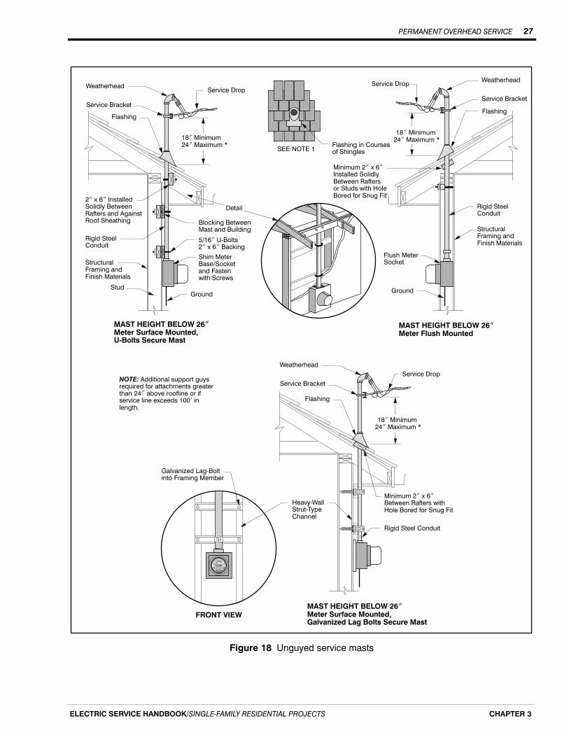
PERMANENT OVERHEAD SERVICE 27
ELECTRIC SERVICE HANDBOOK/SINGLE‐FAMILY RESIDENTIAL PROJECTS CHAPTER 3
2� x 6� InstalledSolidly BetweenRafters and AgainstRoof Sheathing
Rigid SteelConduit
Flashing
Shim MeterBase/Socketand Fastenwith Screws
5/16� U‐Bolts2� x 6� Backing
18� Minimum 24� Maximum *
StructuralFraming andFinish Materials
Stud
Blocking BetweenMast and Building
Ground
Service Bracket
Service Drop
Rigid SteelConduit
Flashing in Coursesof ShinglesSEE NOTE 1
Weatherhead
Flashing
Service Bracket
18� Minimum 24� Maximum *
Flush MeterSocket
StructuralFraming andFinish Materials
Minimum 2� x 6�Installed Solidly Between Rafters or Studs with HoleBored for Snug Fit
Detail
Service Drop
Ground
Weatherhead
Heavy‐WallStrut‐TypeChannel
Service Drop
Minimum 2� x 6�Between Rafters withHole Bored for Snug Fit
FRONT VIEW
Galvanized Lag‐Boltinto Framing Member
Flashing
18� Minimum 24� Maximum *
Service Bracket
Weatherhead
Rigid Steel Conduit
MAST HEIGHT BELOW 26�Meter Surface Mounted,Galvanized Lag Bolts Secure Mast
MAST HEIGHT BELOW 26�Meter Surface Mounted,U‐Bolts Secure Mast
MAST HEIGHT BELOW 26�Meter Flush Mounted
NOTE: Additional support guysrequired for attachments greaterthan 24� above roofline or ifservice line exceeds 100� inlength.
Figure 18 Unguyed service masts
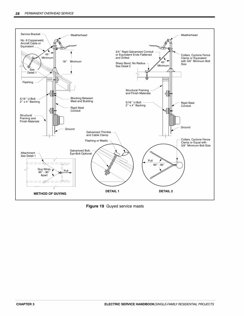
PERMANENT OVERHEAD SERVICE28
ELECTRIC SERVICE HANDBOOK/SINGLE‐FAMILY RESIDENTIAL PROJECTSCHAPTER 3
Weatherhead
Flashing
5/16� U‐Bolt2� x 4� Backing
StructuralFraming andFinish Materials
Blocking BetweenMast and Building
Ground
Service Bracket
Rigid SteelConduit
DETAIL 1
SeeDetail 1
No. 6 Copperweld,Aircraft Cable orEquivalent
45�
Minimum
Guy Wires60� ‐ 90�
Apart
AttachmentSee Detail 1
Galvanized Thimbleand Cable Clamp
Flashing or Mastic
Galvanized Bolt;Eye‐Bolt Optional
45�
Minimum
3/4� Rigid Galvanized Conduitor Equivalent Ends Flattenedand Drilled
Sharp Bend; No Radius.See Detail 2
Structural Framingand Finish Materials
5/16� U‐Bolt2� x 4� Backing
Collars, Cyclone FenceClamp or Equivalentwith 3/8� Minimum BoltSize
DETAIL 2
Collars, Cyclone FenceClamp or Equal with3/8� Minimum Bolt Size
60� ‐ 90�Pull
Ground
Rigid SteelConduit
Weatherhead
METHOD OF GUYING
Pull
18� Minimum
Figure 19 Guyed service masts

PERMANENT OVERHEAD SERVICE 29
ELECTRIC SERVICE HANDBOOK/SINGLE‐FAMILY RESIDENTIAL PROJECTS CHAPTER 3
Additional mast supports (guy or brace)
Additional mast supports, typically a guy or a brace, are required for any service line if:
� The service line is over 100 feet long; or,
� The point of attachment is more than 24 inches above your roof (see Figure 19).
Guys and braces are installed to prevent the weight of the service line from pulling yourservice mast away from your home or damaging your roof.
Further information regarding guying and bracing service masts is available in the NEC.
Screw-in service knobs
For new or altered overhead service lines, you must provide a substantial point ofattachment that meets NEC requirements. Older type screw-in service knobs attached tothe home’s wall are often inadequate to support modern triplexed service lines. PSE mayprohibit use of service knobs if deemed inadequate.
Service entrance equipment installation requirements
After you have determined the meter base/socket location, the service route, the height ofyour service mast, and the size of your service (200 A, 400 A, etc.); you are ready tobegin installing your service entrance equipment.
Once you have installed your meter base/socket and mast you are ready to provide andinstall your service entrance conductor. The service entrance conductor is the wire that isconnected to the top lugs in your meter base/socket and runs up through the service mast.
The service entrance conductors must be sized according to the NEC and to the rating ofyour meter base/socket. When installing the wire, leave at least 18 inches of it exposed atthe end of the weatherhead to allow PSE to connect your service line to it. When youinstall your meter base/socket, make sure the center of the meter will be between 4 and6 feet (5 feet preferred) above finished ground level.
If you have any questions regarding the installation of your service equipment, wesuggest that you refer to the NEC, call the inspecting agency for your area, or contact anelectrical contractor.
Manufactured homes
If you are installing an overhead service to a manufactured home, our service equipmentcan be installed one of two ways:
1. On a customer-owned meter pole, or
2. On the manufactured home, if both of these conditions are met:
a. The manufacturer installed the service equipment at the time the home wasbuilt, and
b. The service equipment meets the meter base/socket requirements listedbelow.
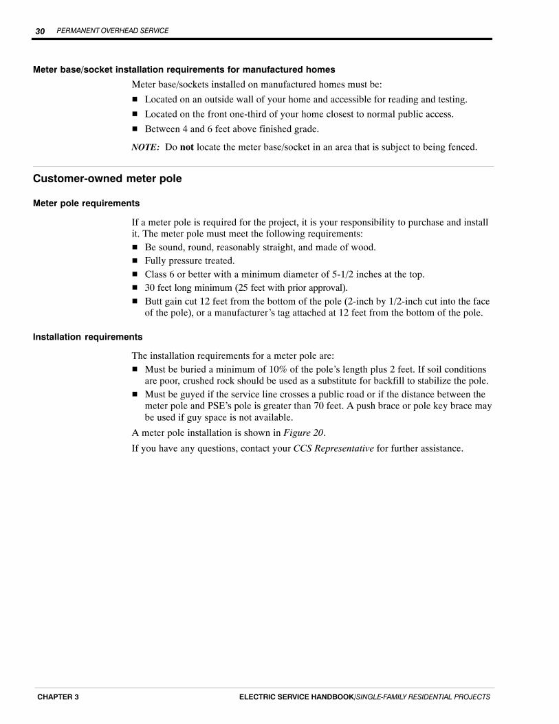
PERMANENT OVERHEAD SERVICE30
ELECTRIC SERVICE HANDBOOK/SINGLE‐FAMILY RESIDENTIAL PROJECTSCHAPTER 3
Meter base/socket installation requirements for manufactured homes
Meter base/sockets installed on manufactured homes must be:
� Located on an outside wall of your home and accessible for reading and testing.
� Located on the front one-third of your home closest to normal public access.
� Between 4 and 6 feet above finished grade.
NOTE: Do not locate the meter base/socket in an area that is subject to being fenced.
Customer-owned meter pole
Meter pole requirements
If a meter pole is required for the project, it is your responsibility to purchase and installit. The meter pole must meet the following requirements:� Be sound, round, reasonably straight, and made of wood.� Fully pressure treated.� Class 6 or better with a minimum diameter of 5-1/2 inches at the top.� 30 feet long minimum (25 feet with prior approval).� Butt gain cut 12 feet from the bottom of the pole (2-inch by 1/2-inch cut into the face
of the pole), or a manufacturer’s tag attached at 12 feet from the bottom of the pole.
Installation requirements
The installation requirements for a meter pole are:� Must be buried a minimum of 10% of the pole’s length plus 2 feet. If soil conditions
are poor, crushed rock should be used as a substitute for backfill to stabilize the pole.� Must be guyed if the service line crosses a public road or if the distance between the
meter pole and PSE’s pole is greater than 70 feet. A push brace or pole key brace maybe used if guy space is not available.
A meter pole installation is shown in Figure 20.
If you have any questions, contact your CCS Representative for further assistance.
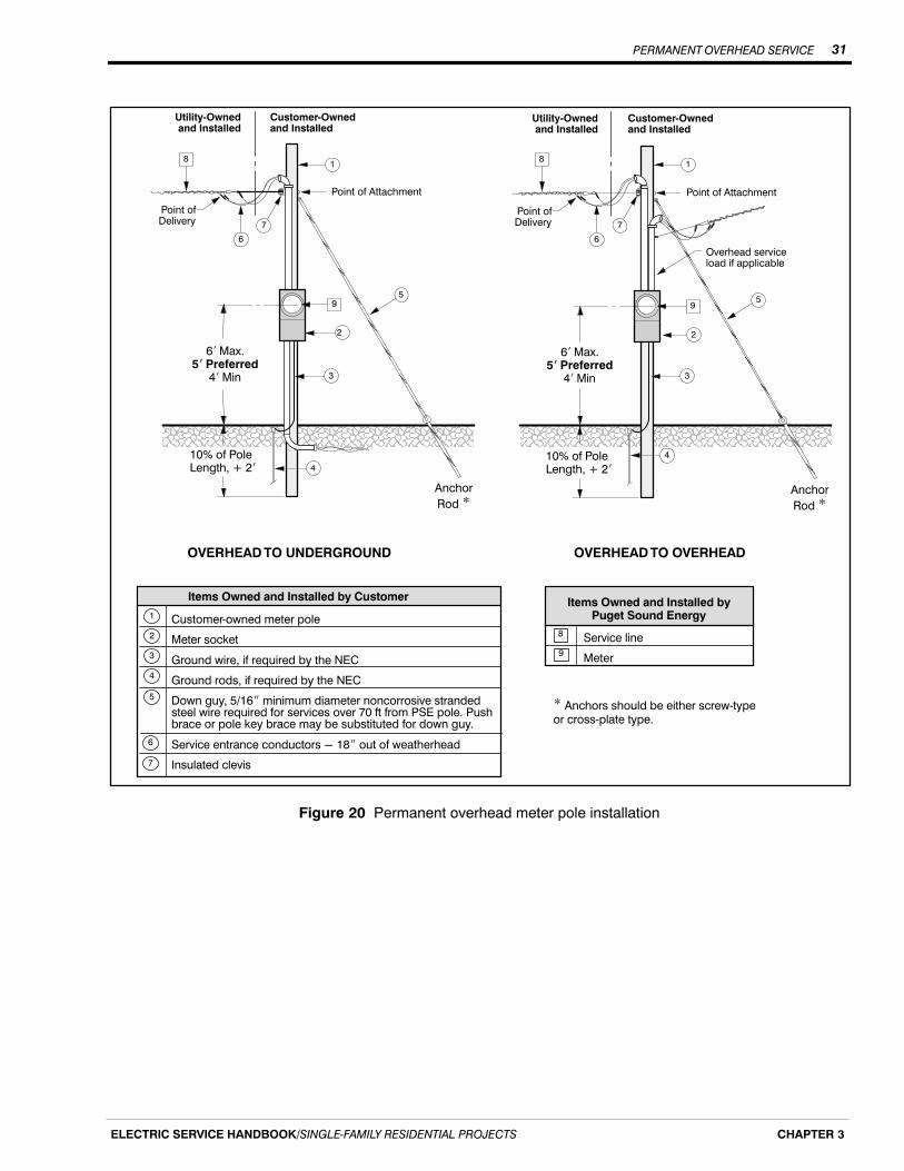
PERMANENT OVERHEAD SERVICE 31
ELECTRIC SERVICE HANDBOOK/SINGLE‐FAMILY RESIDENTIAL PROJECTS CHAPTER 3
ÌÌÌÌÌÌÌÌÌÌÌÌÌÌÌÌÌÌÌÌÌÌÌÌÌÌÌÌ
ÌÌÌÌÌÌÌÌÌÌÌÌÌÌÌÌÌÌÌÌÌÌÌÌÌÌÌÌÌÌ
ÇÇÇÇÇÇÇÇÇÇÇÇÇÇÇÇÇÇÇÇÇÇÇÇÇÇÇÇÇÇÇÇÇÇÇÇÇÇÇÇÇÇÇÇÇÇÇÇÇÇÇÇÇÇÇÇÇÇÇÇÇÇÇÇÇÇÇÇÇ
ÇÇÇÇÇÇÇÇÇ
6� Max.5� Preferred
4� Min
Anchor
Rod *
Utility‐Ownedand Installed
Customer‐Ownedand Installed
Point of Attachment
OVERHEAD TO UNDERGROUND
1
Point ofDelivery
9
8
Items Owned and Installed byPuget Sound EnergyCustomer‐owned meter pole
Meter socket
Ground wire, if required by the NEC
Ground rods, if required by the NEC
Down guy, 5/16� minimum diameter noncorrosive strandedsteel wire required for services over 70 ft from PSE pole. Pushbrace or pole key brace may be substituted for down guy.
Service entrance conductors - 18� out of weatherhead
Insulated clevis
Items Owned and Installed by Customer
6
5
7
1
2
3
4
Service line
Meter
ÇÇÇÇÇÇÇÇÇÇÇÇÇÇÇÇÇÇÇÇÇÇÇÇÇÇÇÇÇÇÇÇÇÇÇÇÇÇÇÇÇÇÇÇÇÇÇÇÇÇÇÇÇÇÇÇÇÇÇÇÇÇÇÇÇÇÇÇÇÇÇÇÇÇÇÇÇÇÇ
ÇÇÇÇÇÇAnchor
Rod *
Utility‐Ownedand Installed
Customer‐Ownedand Installed
Point of Attachment
Point ofDelivery
Overhead serviceload if applicable
10% of PoleLength, + 2�
OVERHEAD TO OVERHEAD
6� Max.5� Preferred
4� Min
* Anchors should be either screw‐typeor cross‐plate type.
10% of PoleLength, + 2�
8
9
4
6
7
2
3
95
4
3
2
5
18
6
7
Figure 20 Permanent overhead meter pole installation

PERMANENT OVERHEAD SERVICE32
ELECTRIC SERVICE HANDBOOK/SINGLE‐FAMILY RESIDENTIAL PROJECTSCHAPTER 3

PRIMARY LINE EXTENSIONS 33
ELECTRIC SERVICE HANDBOOK/SINGLE‐FAMILY RESIDENTIAL PROJECTS CHAPTER 4
Chapter 4
Primary Line Extensions
If your new residence is not located close to existing primary electrical facilities, aprimary line extension is required to place a transformer close to your structure. Primaryline extensions are typically underground facilities.
Customer responsibility
PSE’s Electric Tariff G, Schedule 85 requires customers to provide the trenching,excavation for vaults and backfill in accordance with PSE standards and work sketch, orcontract with PSE to provide this work at its estimated cost.
If you require a primary line extension, submit Electric Service ApplicationSingle-Family Residential 100E (Form 4414). All forms can be downloaded atPSE.com.
Inspection/coordination
PSE shall assign a Project Manager to oversee the trenching, equipmentplacement/installation, and backfilling.
� Work shall be subject to the inspection and satisfaction of PSE.
� No work shall be backfilled, covered, or concealed until it has been inspected andapproved by the inspector.
Site preparation
The following site requirements must be met before the installation can begin.
� The trench route shall be clear of spoils, construction materials, and any otherobstacles.
� The site shall be at final grade or acceptable subgrade in the area of construction.
� The front property line shall be surveyed and staked.
Customer-provided trench
Trench widthThe minimum trench width is 18 inches. The excavator may need to increase the trenchwidth depending on the other conduits/lines being installed in the trench.
When increasing the trench width, remember to allow adequate horizontal separationbetween PSE’s electrical conduits/cables, gas lines, and other utility-owned conduits andlines in the trench (see Figure 21).
Continued on next page
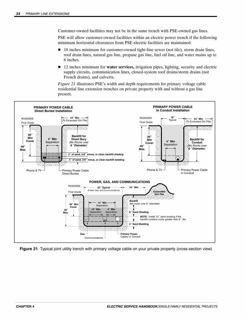
PRIMARY LINE EXTENSIONS34
ELECTRIC SERVICE HANDBOOK/SINGLE‐FAMILY RESIDENTIAL PROJECTSCHAPTER 4
Customer-owned facilities may not be in the same trench with PSE-owned gas lines.
PSE will allow customer-owned facilities within an electric power trench if the followingminimum horizontal clearances from PSE electric facilities are maintained:
� 18 inches minimum for customer-owned tight-line sewer (not tile), storm drain lines,roof drain lines, natural gas line, propane gas line, fuel oil line, and water mains up to6 inches.
� 12 inches minimum for water services, irrigation pipes, lighting, security and electricsupply circuits, communication lines, closed-system roof drains/storm drains (notFrench drains), and culverts.
Figure 21 illustrates PSE’s width and depth requirements for primary voltage cableresidential line extension trenches on private property with and without a gas linepresent.
PRIMARY POWER CABLEIn Conduit Installation
Final Grade
ÑÑÑÑÑÑÑÑÑÑÑÑÑÑÑÑÑÑÑÑÑÑÑÑÑÑÑÑÑÑÑÑÑÑÑÑÑÑÑÑÑÑÑÑÑÑÑÑÑÑÑÑÑÑÑÑÑÑÑÑÑÑÑÑÑÑÑÑÑÑÑÑÑÑÑÑÑ
36�Min
Cover
Backfill forConduit
(No Rocks over6� Diameter)
Phone & TV
4� MinSeparation
48�Max.
ROADSIDE
Primary Power CableDirect Buried
3� of sand, 5/8� minus, or clean backfill shading
PRIMARY POWER CABLEDirect Buried Installation
Final Grade
ÑÑÑÑÑÑÑÑÑÑÑÑÑÑÑÑÑÑÑÑÑÑÑÑÑÑÑÑÑÑÑÑÑÑÑÑÑÑÑÑÑÑÑÑÑÑÑÑÑÑÑÑÑÑÑÑÑÑÑÑÑÑÑÑÑÑÑÑÑÑÑÑÑÑÑÑÑ
36�Min
Cover
24� Min(To Excavated Dirt Pile)
Backfill forDirect Bury
(No Rocks over6� Diameter)
Phone & TV
4� MinSeparation
48�Max.
ROADSIDE
Primary Power Cablein Conduit
24� Min(To Excavated Dirt Pile)
24� Min
Final Grade
32� Typical(Power, Gas, and Communications)
ÑÑÑÑÑÑÑÑÑÑÑÑÑÑÑÑÑÑÑÑÑÑÑÑÑÑÑÑÑÑÑÑÑÑÑÑÑÑÑÑÑÑÑÑÑÑÑÑÑÑÑÑÑÑÑÑÑÑÑÑÑÑÑÑÑÑÑÑÑÑÑÑÑÑÑÑÑÑÑÑÑÑÑÑÑÑÑÑÑÑÑÑÑÑÑÑÑÑ
Communications
Primary PowerCables or Conduit
Gas
ÑÑÑÑÑÑÑÑÑÑÑÑÑÑÑÑÑÑÑÑÑÑÑÑ
ExcavatedDirt Pile
POWER, GAS, AND COMMUNICATIONS
4� MinSeparation
12� MinSeparation
ROADSIDE
36� MinCover
48�Max.
4� Sand Bedding
6� Sand Shading
Backfill (No rocks over 6� diameter)
NOTE: Install 12� sand shading if thebackfill contains rocks greater than 6� dia.
12� MinSeparation
18�Typical
3� of sand, 5/8� minus, or clean backfill bedding
Figure 21 Typical joint utility trench with primary voltage cable on your private property (cross-section view)

PRIMARY LINE EXTENSIONS 35
ELECTRIC SERVICE HANDBOOK/SINGLE‐FAMILY RESIDENTIAL PROJECTS CHAPTER 4
Trench excavating requirements
The following requirements for the trench must be met before power conduits/cables willbe installed.
� When you trench in right-of-way on PSE’s behalf, the governing jurisdictions issuepublic roadway use permits to PSE.
� For trench work provided by you within a public right-of-way or a PSE easement,PSE requires that you use a Washington State licensed and bonded contractor andcomplete and sign a PSE trenching agreement form.
� Trench work within a public right-of-way must meet the erosion and sediment controlrequirements of the local jurisdiction.
� Provide a signed Excavation Requirements & Final Grade Certification documentsupplied by your Project Manager or PSE Representative.
� The trench shall be excavated according to the trench detail and PSE’s work sketch.
� The trench shall be straight and the trench bottom shall be smooth, level, and freefrom obstructions, sharp objects, or rocks larger than 1/2 inches.
� Excavated or loose material shall be placed at least 2 feet from the field edge of thetrench.
� Water shall be removed by pumping or draining following the erosion and sedimentcontrol requirements of the local jurisdiction.
NOTE: Trenches or vault excavations that are 4 feet deep or greater require specialsloping. Contact your PSE Project Manager for these requirements.
Trench and backfill requirements for electric
PSE will not energize its facilities until backfill is completed.
You are responsible for the following:
� Providing a minimum 3-inch layer of sand, 5/8-inch minus, or clean backfill (withrocks no larger than 5/8-inches and no sharp objects) placed below and above directburied cables. The remaining trench shall be backfilled with soil that is free of rockslarger than 6 inches and foreign objects.
� If the cable is in conduit, backfill the trench with soil that is free of foreign objectsand rocks larger than 6 inches. Bedding and shading with a 3-inch layer of sand,5/8-inch minus, or clean backfill is not required.
PRIMARY LINE EXTENSIONS36
ELECTRIC SERVICE HANDBOOK/SINGLE‐FAMILY RESIDENTIAL PROJECTSCHAPTER 4
Trench and backfill requirements if a natural gas line is in the trench
You must provide a 6-inch or 12-inch layer of sand above (depending on the backfill soilconditions), and a 4-inch layer of sand bedding below the utilities before backfilling (seeFigure 21).
You are responsible for the following:
� Completing backfill as soon as practical after facilities are placed and inspected.
� Carefully placing backfill to prevent damage or movement of the cables or conduit.
� Cost of damages to PSE facilities caused by improper backfill or compaction.
� Relocation costs due to change in grade or alignment.
CAUTION: Do not use a compactor directly over the power conduit(s) until at least30 inches of backfill is in place, so that the compactor will not damage the cables orconduit. Do not penetrate the soil deeper than 3 inches during compaction with abackhoe compactor.
VaultsPSE is responsible for furnishing and installing all primary vaults required for yourelectric service.
Vault excavation procedure
1. Locate the vault according to PSE’s work sketch drawing.
2. Determine a suitable place to put the spoils (at least 2 feet from the edge of theexcavation).
3. Excavate so the vault is in correct alignment with the trench and so that conduits forprimary voltage cables (if required) can be brought straight into the front half ofthe vault.
4. Dig a hole large enough to accommodate the transformer or junction box vault andallow for easy installation and compaction (see Figures 22 through 24).
5. Remove debris and level the bottom of the excavation.
6. Prepare the bottom of the excavation so that the vault will rest on solid undisturbedearth with a 6-inch base of crushed rock. This prevents vault settling.
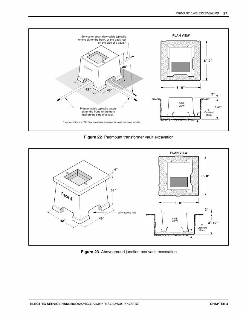
PRIMARY LINE EXTENSIONS 37
ELECTRIC SERVICE HANDBOOK/SINGLE‐FAMILY RESIDENTIAL PROJECTS CHAPTER 4
SIDEVIEW
ÑÑÑÑÑÑÑ
ÑÑÑÑÑÑÑÑÑÑÑÑÑÑÑÑÑÑÑÑÑÑÑÑÑÑÑÑÑÑÑÑÑÑÑÑÑÑÑÑÑÑÑÑÑÑÑÑÑÑÑÑÑÑÑÑ
PLAN VIEW
6�‐�0�
6�‐�0�
6�Crushed
Rock
2�
3�‐6�
42� 48�
38�
Primary cable typically enterseither the front, or the fronthalf on the side of a vault.
Service or secondary cable typicallyenters either the back, or the back half
on the side of a vault.*
* Approval from a PSE Representative required for vault entrance location.
Figure 22 Padmount transformer vault excavation
SIDEVIEW42�
48�
38�
4�
ÑÑÑÑÑÑÑÑÑÑÑÑÑÑÑÑÑÑÑÑÑÑÑÑÑÑÑÑÑÑÑÑÑÑÑÑÑÑÑÑÑÑÑÑÑÑÑÑÑÑÑÑÑÑÑÑ
6�‐�0�
6�‐�0�
ÑÑÑÑÑÑÑÑÑÑÑÑÑÑ
6�Crushed
Rock
2�
3�‐�10�
PLAN VIEW
Wire access hole
Figure 23 Aboveground junction box vault excavation
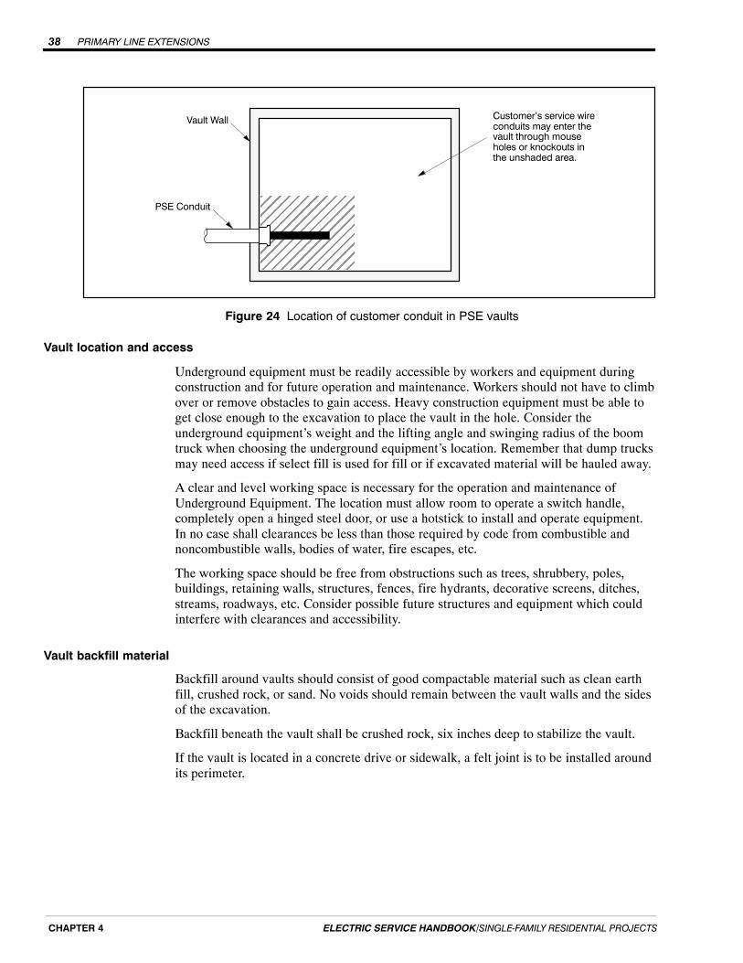
PRIMARY LINE EXTENSIONS38
ELECTRIC SERVICE HANDBOOK/SINGLE‐FAMILY RESIDENTIAL PROJECTSCHAPTER 4
Vault Wall Customer's service wireconduits may enter thevault through mouseholes or knockouts inthe unshaded area.
ÉÉÉÉÉÉÉÉÉÉÉÉÉÉÉÉÉÉÉÉÉÉÉÉÉÉÉÉÉÉ
PSE Conduit
Figure 24 Location of customer conduit in PSE vaults
Vault location and access
Underground equipment must be readily accessible by workers and equipment duringconstruction and for future operation and maintenance. Workers should not have to climbover or remove obstacles to gain access. Heavy construction equipment must be able toget close enough to the excavation to place the vault in the hole. Consider theunderground equipment’s weight and the lifting angle and swinging radius of the boomtruck when choosing the underground equipment’s location. Remember that dump trucksmay need access if select fill is used for fill or if excavated material will be hauled away.
A clear and level working space is necessary for the operation and maintenance ofUnderground Equipment. The location must allow room to operate a switch handle,completely open a hinged steel door, or use a hotstick to install and operate equipment.In no case shall clearances be less than those required by code from combustible andnoncombustible walls, bodies of water, fire escapes, etc.
The working space should be free from obstructions such as trees, shrubbery, poles,buildings, retaining walls, structures, fences, fire hydrants, decorative screens, ditches,streams, roadways, etc. Consider possible future structures and equipment which couldinterfere with clearances and accessibility.
Vault backfill material
Backfill around vaults should consist of good compactable material such as clean earthfill, crushed rock, or sand. No voids should remain between the vault walls and the sidesof the excavation.
Backfill beneath the vault shall be crushed rock, six inches deep to stabilize the vault.
If the vault is located in a concrete drive or sidewalk, a felt joint is to be installed aroundits perimeter.

PRIMARY LINE EXTENSIONS 39
ELECTRIC SERVICE HANDBOOK/SINGLE‐FAMILY RESIDENTIAL PROJECTS CHAPTER 4
Continuous conduit systems
When PSE’s design includes a continuous conduit system, PSE will supply conduit forprimary voltage cables.
Customer-supplied conduits
You may supply and install discontinuous primary conduit for construction convenience.
If you supply the conduit for primary voltage cable, it will be owned and maintained byPSE and shall meet the following specifications:
� PVC electrical grade, Schedule 40 (or Schedule 80 if required in poor soilconditions).
� Gray in color.
� 2-, 3-, 4-, or 6-inch diameters as specified on the work sketch.
� Conduit bends shall be long radius bends, 36-inch minimum radius.
� Meet requirements in ASTM F 512 and NEMA TC 2.
Terminating conduit at transformer
When installing the conduit, stop 2 feet short of the entrance into the wire access holelocated at the bottom of the mini pad transformer handhole.

PRIMARY LINE EXTENSIONS40
ELECTRIC SERVICE HANDBOOK/SINGLE‐FAMILY RESIDENTIAL PROJECTSCHAPTER 4
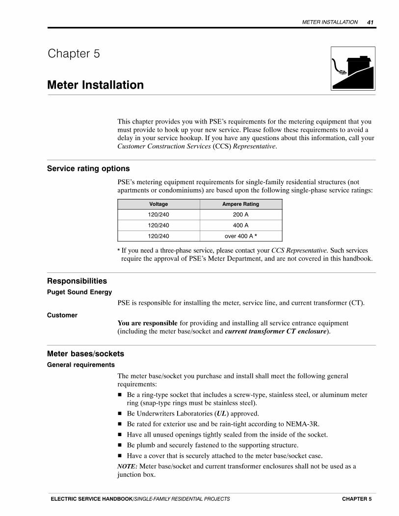
METER INSTALLATION 41
ELECTRIC SERVICE HANDBOOK/SINGLE‐FAMILY RESIDENTIAL PROJECTS CHAPTER 5
Chapter 5
Meter Installation
This chapter provides you with PSE’s requirements for the metering equipment that youmust provide to hook up your new service. Please follow these requirements to avoid adelay in your service hookup. If you have any questions about this information, call yourCustomer Construction Services (CCS) Representative.
Service rating options
PSE’s metering equipment requirements for single-family residential structures (notapartments or condominiums) are based upon the following single-phase service ratings:
Voltage Ampere Rating
120/240 200 A
120/240 400 A
120/240 over 400 A *
* If you need a three-phase service, please contact your CCS Representative. Such services require the approval of PSE’s Meter Department, and are not covered in this handbook.
ResponsibilitiesPuget Sound Energy
PSE is responsible for installing the meter, service line, and current transformer (CT).
CustomerYou are responsible for providing and installing all service entrance equipment(including the meter base/socket and current transformer CT enclosure).
Meter bases/socketsGeneral requirements
The meter base/socket you purchase and install shall meet the following generalrequirements:
� Be a ring-type socket that includes a screw-type, stainless steel, or aluminum meterring (snap-type rings must be stainless steel).
� Be Underwriters Laboratories (UL) approved.
� Be rated for exterior use and be rain-tight according to NEMA-3R.
� Have all unused openings tightly sealed from the inside of the socket.
� Be plumb and securely fastened to the supporting structure.
� Have a cover that is securely attached to the meter base/socket case.
NOTE: Meter base/socket and current transformer enclosures shall not be used as ajunction box.

METER INSTALLATION42
ELECTRIC SERVICE HANDBOOK/SINGLE‐FAMILY RESIDENTIAL PROJECTSCHAPTER 5
Meter base/socket location
For single-family residences and manufactured and mobile homes, you are required toinstall your meter base/socket in a place that is accessible to PSE. All locations aresubject to approval by a PSE Representative. If you have questions regarding meterlocations, call your CCS Representative.
Meter bases/sockets and current transformer (CT) enclosures must be located:
� Outside.
� On the front one-third of your home closest to normal public access.
� In an area that is not subject to being fenced or walled in (such as patios, decks,porches, breezeways, backyards, and carports).
� On a structure that is owned by you.
These locations allow PSE to:
� Read your meter in a cost-effective manner.
� Maintain your meter efficiently.
� Disconnect your service in case of fire.
Grounding requirements
All meter bases/sockets, enclosures, and conduit shall be bonded and grounded inaccordance with the NEC.
Clearance requirements for meter installations
The following clearances are required around all meter installations. It is yourresponsibility to provide and maintain these clearances.
� The center of the meter shall be between 4 and 6 feet above finished grade (except meter pedestals)—5 feet is preferred.
� A working space of 36 inches wide by 36 inches deep (see Figure 25) is requiredaround the meter. This working space is to be kept clear of any obstructions includinglandscaping.
� There shall be a minimum horizontal and vertical clearance of 10 inches between thecenter of the electric meter and any obstruction (see Figure 25).
� If a recessed meter bases/socket is installed, a 10-inch clearance is required from themeter to the closest portion of the wall (see Figure 26).
� If a flush or recessed meter base/socket is installed, the siding or finished surface ofthe structure shall not overlap the cover of the meter base/socket.
� If a flush or recessed meter base/socket is installed, space must be left around thelocking tab for PSE to install a meter seal.
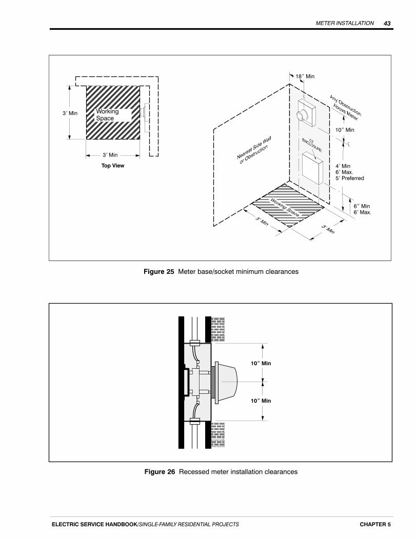
METER INSTALLATION 43
ELECTRIC SERVICE HANDBOOK/SINGLE‐FAMILY RESIDENTIAL PROJECTS CHAPTER 5
ÌÌÌÌÌÌÌÌÌÌÌÌÌÌÌÌÌÌÌÌÌÌÌÌÌÌÌÌÌÌÌÌÌÌÌ
4� Min6� Max.5� Preferred
6� Min6� Max.
10� Min
ÍÍÍÍÍÍÍÍÍÍÍÍÍÍÍÍÍÍÍÍÍÍÍÍÍÍÍÍÍÍÍÍÍÍÍÍ
WorkingSpace
3� Min
3� Min
Top View
18� Min
Figure 25 Meter base/socket minimum clearances
ÁÁÁÁÁÁÁÁ
ÁÁÁÁÁÁÁÁ
10� Min
10� Min
Figure 26 Recessed meter installation clearances
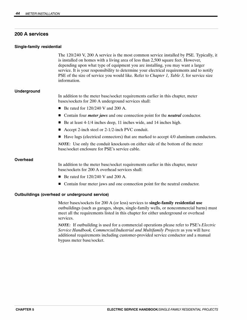
METER INSTALLATION44
ELECTRIC SERVICE HANDBOOK/SINGLE‐FAMILY RESIDENTIAL PROJECTSCHAPTER 5
200 A services
Single-family residential
The 120/240 V, 200 A service is the most common service installed by PSE. Typically, itis installed on homes with a living area of less than 2,500 square feet. However,depending upon what type of equipment you are installing, you may want a largerservice. It is your responsibility to determine your electrical requirements and to notifyPSE of the size of service you would like. Refer to Chapter 1, Table 3, for service sizeinformation.
UndergroundIn addition to the meter base/socket requirements earlier in this chapter, meterbases/sockets for 200 A underground services shall:
� Be rated for 120/240 V and 200 A.
� Contain four meter jaws and one connection point for the neutral conductor.
� Be at least 4-1/4 inches deep, 11 inches wide, and 14 inches high.
� Accept 2-inch steel or 2-1/2-inch PVC conduit.
� Have lugs (electrical connectors) that are marked to accept 4/0 aluminum conductors.
NOTE: Use only the conduit knockouts on either side of the bottom of the meterbase/socket enclosure for PSE’s service cable.
OverheadIn addition to the meter base/socket requirements earlier in this chapter, meterbase/sockets for 200 A overhead services shall:
� Be rated for 120/240 V and 200 A.
� Contain four meter jaws and one connection point for the neutral conductor.
Outbuildings (overhead or underground service)
Meter bases/sockets for 200 A (or less) services to single-family residential useoutbuildings (such as garages, shops, single-family wells, or noncommercial barns) mustmeet all the requirements listed in this chapter for either underground or overheadservices.
NOTE: If outbuilding is used for a commercial operations please refer to PSE’s ElectricService Handbook, Commercial/Industrial and Multifamily Projects as you will haveadditional requirements including customer-provided service conductor and a manualbypass meter base/socket.
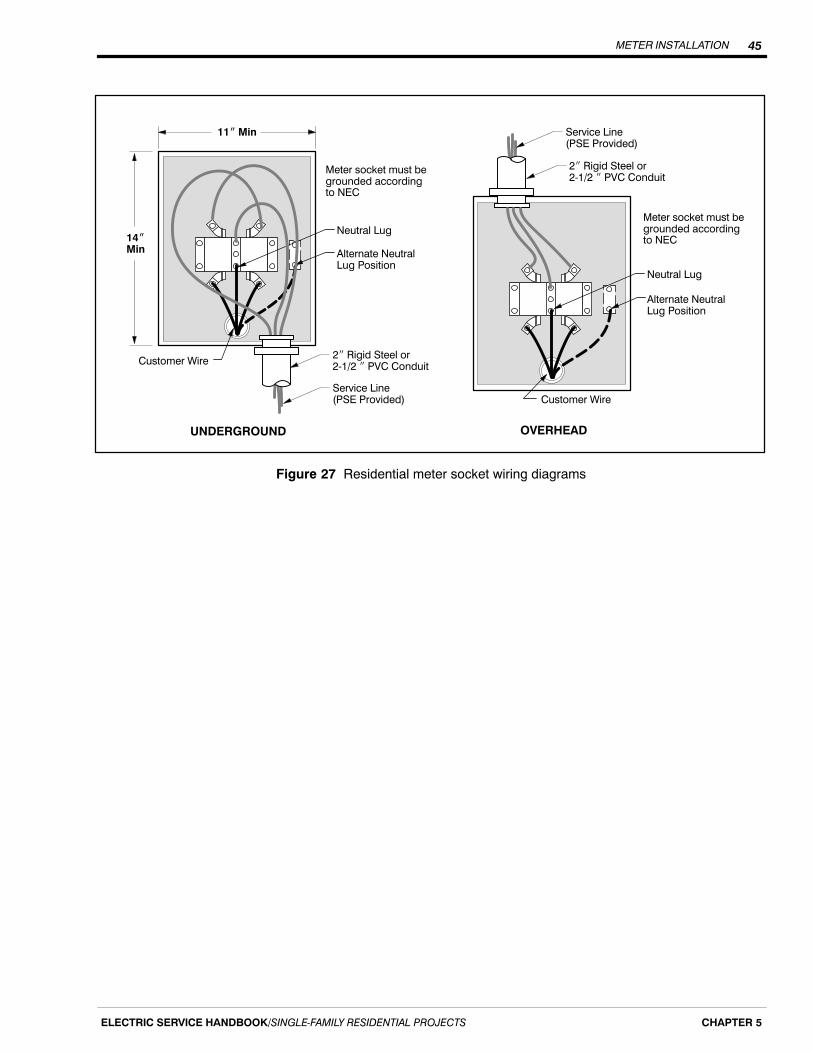
METER INSTALLATION 45
ELECTRIC SERVICE HANDBOOK/SINGLE‐FAMILY RESIDENTIAL PROJECTS CHAPTER 5
14�Min
Neutral Lug
Meter socket must begrounded accordingto NEC
Alternate Neutral Lug Position
2� Rigid Steel or 2‐1/2 � PVC Conduit
Service Line(PSE Provided)
Customer Wire
UNDERGROUND
11� Min
Neutral Lug
Alternate Neutral Lug Position
Customer Wire
OVERHEAD
Meter socket must begrounded accordingto NEC
2� Rigid Steel or 2‐1/2 � PVC Conduit
Service Line(PSE Provided)
Figure 27 Residential meter socket wiring diagrams
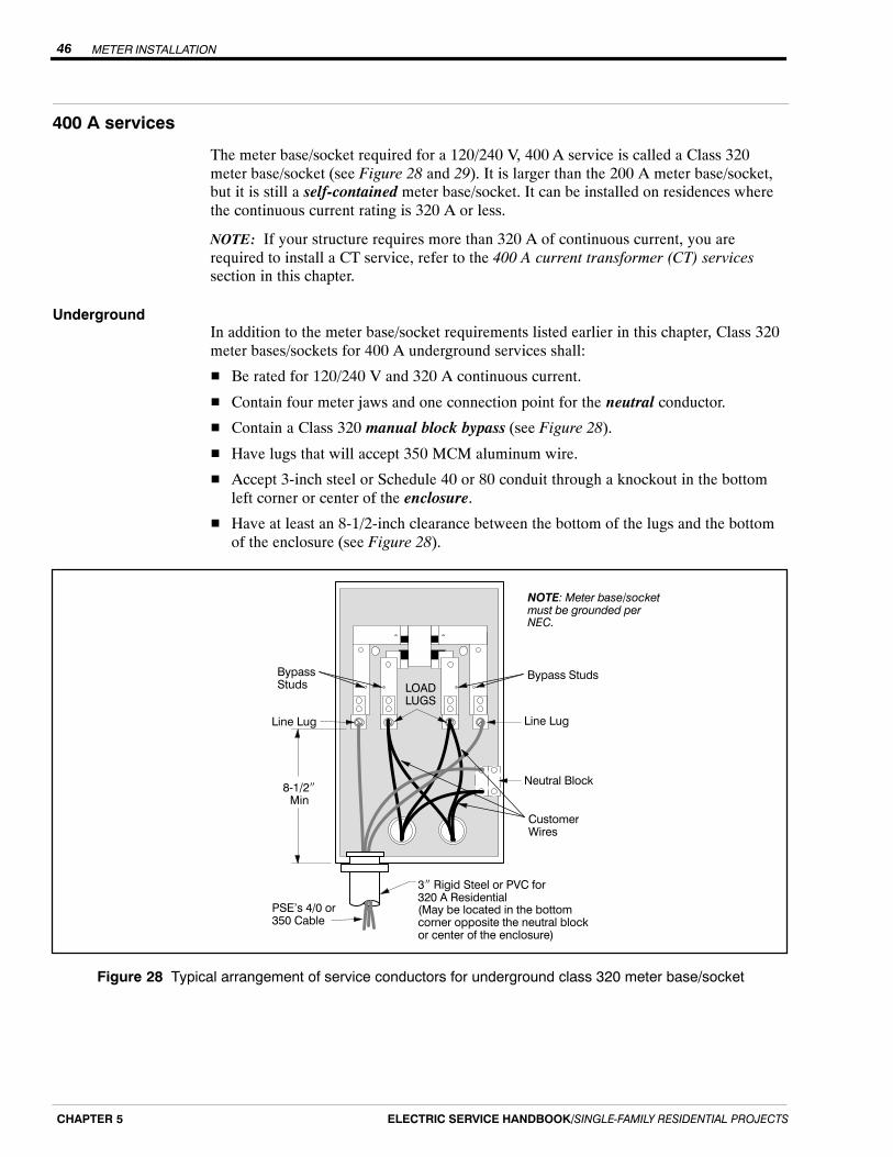
METER INSTALLATION46
ELECTRIC SERVICE HANDBOOK/SINGLE‐FAMILY RESIDENTIAL PROJECTSCHAPTER 5
400 A services
The meter base/socket required for a 120/240 V, 400 A service is called a Class 320meter base/socket (see Figure 28 and 29). It is larger than the 200 A meter base/socket,but it is still a self-contained meter base/socket. It can be installed on residences wherethe continuous current rating is 320 A or less.
NOTE: If your structure requires more than 320 A of continuous current, you arerequired to install a CT service, refer to the 400 A current transformer (CT) servicessection in this chapter.
UndergroundIn addition to the meter base/socket requirements listed earlier in this chapter, Class 320meter bases/sockets for 400 A underground services shall:
� Be rated for 120/240 V and 320 A continuous current.
� Contain four meter jaws and one connection point for the neutral conductor.
� Contain a Class 320 manual block bypass (see Figure 28).
� Have lugs that will accept 350 MCM aluminum wire.
� Accept 3-inch steel or Schedule 40 or 80 conduit through a knockout in the bottomleft corner or center of the enclosure.
� Have at least an 8-1/2-inch clearance between the bottom of the lugs and the bottomof the enclosure (see Figure 28).
8‐1/2�Min
Bypass Studs
3� Rigid Steel or PVC for320 A Residential(May be located in the bottomcorner opposite the neutral blockor center of the enclosure)
Customer Wires
Line Lug Line Lug
Bypass Studs LOAD
LUGS
Neutral Block
PSE's 4/0 or350 Cable
NOTE: Meter base/socketmust be grounded perNEC.
Figure 28 Typical arrangement of service conductors for underground class 320 meter base/socket
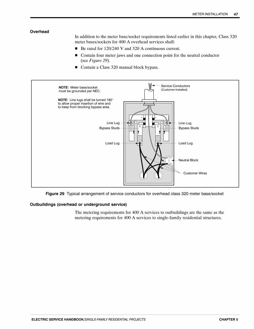
METER INSTALLATION 47
ELECTRIC SERVICE HANDBOOK/SINGLE‐FAMILY RESIDENTIAL PROJECTS CHAPTER 5
OverheadIn addition to the meter base/socket requirements listed earlier in this chapter, Class 320meter bases/sockets for 400 A overhead services shall:
� Be rated for 120/240 V and 320 A continuous current.
� Contain four meter jaws and one connection point for the neutral conductor (see Figure 29).
� Contain a Class 320 manual block bypass.
NOTE: Meter base/socketmust be grounded per NEC.
Service Conductors(Customer‐Installed)
Customer Wires
Bypass Studs
Line Lug Line Lug
Bypass Studs
Load Lug
NOTE: Line lugs shall be turned 180�to allow proper insertion of wire andto keep from blocking bypass area.
Neutral Block
Load Lug
Figure 29 Typical arrangement of service conductors for overhead class 320 meter base/socket
Outbuildings (overhead or underground service)
The metering requirements for 400 A services to outbuildings are the same as themetering requirements for 400 A services to single-family residential structures.
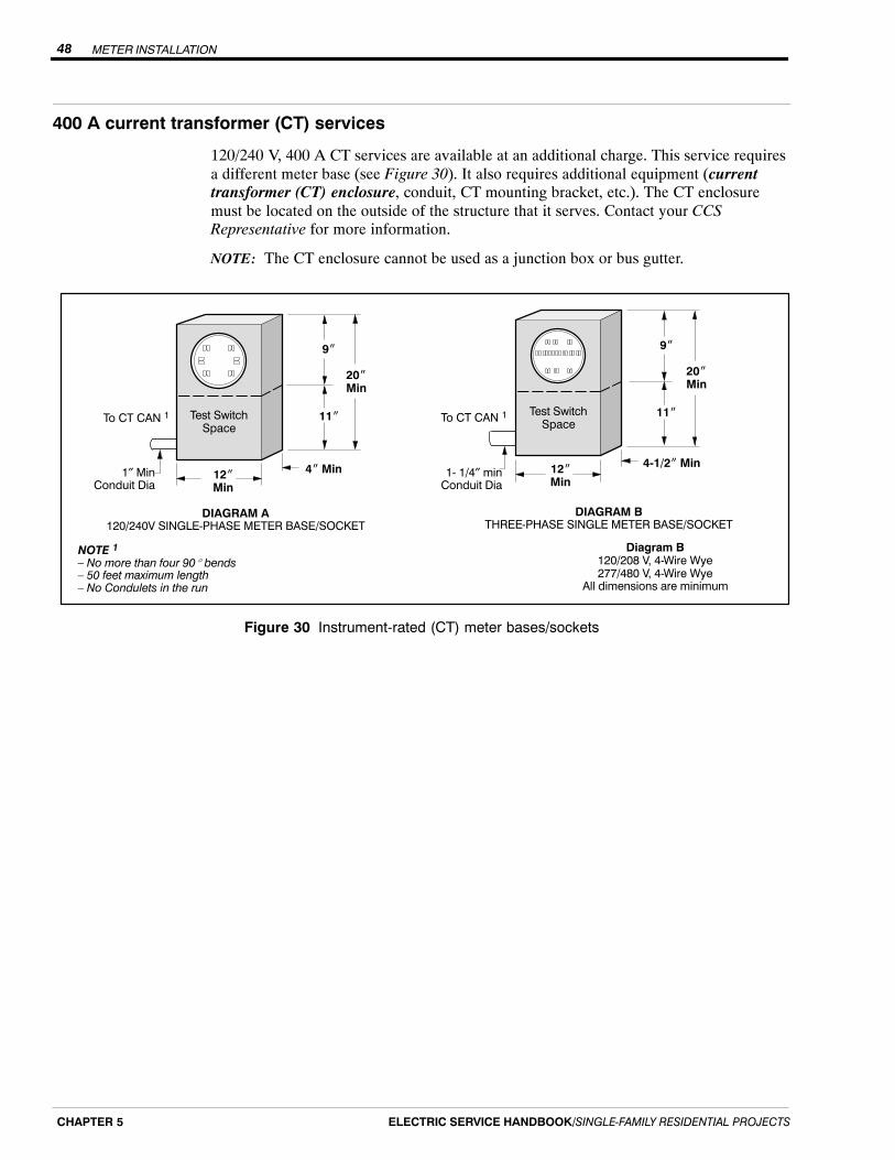
METER INSTALLATION48
ELECTRIC SERVICE HANDBOOK/SINGLE‐FAMILY RESIDENTIAL PROJECTSCHAPTER 5
400 A current transformer (CT) services
120/240 V, 400 A CT services are available at an additional charge. This service requiresa different meter base (see Figure 30). It also requires additional equipment (currenttransformer (CT) enclosure, conduit, CT mounting bracket, etc.). The CT enclosuremust be located on the outside of the structure that it serves. Contact your CCSRepresentative for more information.
NOTE: The CT enclosure cannot be used as a junction box or bus gutter.
DIAGRAM A120/240V SINGLE‐PHASE METER BASE/SOCKET
DIAGRAM BTHREE‐PHASE SINGLE METER BASE/SOCKET
20�Min
12�Min
Test SwitchSpace
4� Min
To CT CAN 1 11�
9�
20�Min
12�Min
Test SwitchSpace
4‐1/2� Min
11�
9�
To CT CAN 1
1″ MinConduit Dia
1‐ 1/4″ minConduit Dia
NOTE 1 – No more than four 90� bends– 50 feet maximum length– No Condulets in the run
Diagram B120/208 V, 4‐Wire Wye277/480 V, 4‐Wire Wye
All dimensions are minimum
Figure 30 Instrument-rated (CT) meter bases/sockets
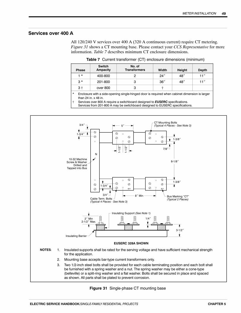
METER INSTALLATION 49
ELECTRIC SERVICE HANDBOOK/SINGLE‐FAMILY RESIDENTIAL PROJECTS CHAPTER 5
Services over 400 A
All 120/240 V services over 400 A (320 A continuous current) require CT metering.Figure 31 shows a CT mounting base. Please contact your CCS Representative for moreinformation. Table 7 describes minimum CT enclosure dimensions.
Table 7 Current transformer (CT) enclosure dimensions (minimum)
PhaseSwitch
AmpacityNo. of
Transformers Width Height Depth
1 * 400‐800 2 24� 48� 11�
3 * 201‐800 3 36� 48� 11�
3 † over 800 3 †
* Enclosure with a side‐opening single‐hinged door is required when cabinet dimension is larger
than 24 in. x 48 in.
† Services over 800 A require a switchboard designed to EUSERC specifications. Services from 201‐800 A may be switchboard designed to EUSERC specifications.
ÑÑ
8� Min
1‐3/8�
1‐3/8�
8‐1/8�
Bus Marking “CT”(Typical 2 Places)
5�
1‐1
/2�
1‐1
/2�
CT Mounting Bolts(Typical 4 Places ‐ See Note 3)
7/8�
3/4�
3/4�
1‐3/4�
1‐3/4�
Cable Term. Bolts(Typical 4 Places ‐ See Note 3)
10‐32 MachineScrew & Washer
Drilled andTapped into Bus
ÑÑÑ ÑÑ
2� Min2‐1/2� Max.
1/4�
3‐1/2�
Insulating Support (See Note 1)
Insulating Barrier
EUSERC 328A SHOWN
N
1. Insulated supports shall be rated for the serving voltage and have sufficient mechanical strength
for the application.
2. Mounting base accepts bar‐type current transformers only.
3. Two 1/2‐inch steel bolts shall be provided for each cable terminating position and each bolt shallbe furnished with a spring washer and a nut. The spring washer may be either a cone‐type
(belleville) or a split‐ring washer and a flat washer. Bolts shall be secured in place and spaced
as shown. All parts shall be plated to prevent corrosion.
NOTES:
Figure 31 Single-phase CT mounting base

METER INSTALLATION50
ELECTRIC SERVICE HANDBOOK/SINGLE‐FAMILY RESIDENTIAL PROJECTSCHAPTER 5

TEMPORARY SERVICES 51
ELECTRIC SERVICE HANDBOOK/SINGLE‐FAMILY RESIDENTIAL PROJECTS CHAPTER 6
Chapter 6
Temporary Services
What this chapter contains
In this chapter you will find answers to questions such as:
� What are the installation requirements for underground and overhead service?
� What are the trenching requirements?
� How do I locate existing underground utilities before I dig?
� How do I get my temporary service energized?
DefinitionA temporary (temp) service is a means of supplying electricity to your site for lessthan one year. Typically, a temporary service provides power for the construction phaseof your project, while provisions are being made for your permanent power system.Temp service is provided underground or overhead depending on available PSE facilities.
Obtaining your temporary service from existing power facilities
The following information applies to your temporary service installation:
� Determine if you need overhead or underground service (see Preface, Figure 1).
� Obtain an electrical work permit.
� Order underground utility locate service by contacting the 811 “Call Before You Dig”hotline two business days before digging.
� Prepare the job site and install your temp service equipment (service post, pedestal,and meter base per illustrations found in this chapter).
� Obtain an electrical inspection approval of your temp service equipment (this is doneby you or your contractor).
� Call PSE to request that your temp service be connected and energized after yourelectrical inspection is complete.
� Apply for permanent service.
� At your request, we will check your site to determine if engineering is required.
If you have any questions, please call Customer Construction Services (CCS) at1-888-321-7779. For information on permanent services, please contact CCS.
TEMPORARY SERVICES52
ELECTRIC SERVICE HANDBOOK/SINGLE‐FAMILY RESIDENTIAL PROJECTSCHAPTER 6
Scheduling
Most temp services are connected to existing power facilities and engineering is notrequired. In these cases temp services are typically energized 3 to 5 days after yourinstallation has passed inspection. Depending on complexity and work volume, timeframes will vary.
Customer charge for service
Charges vary due to the type of system we have in your area. Your CCS Representativewill explain current temp service fees.
Temporary meter base/socket requirements
You are required to provide a meter socket with the following specifications:
� A ring-type socket that includes a screw-type, stainless steel, or aluminum meter ring(snap-type rings must be stainless steel).
� Rated 120/240 V
� Single-phase
� Minimum rating of 100 A
� Maximum rating of 200 A
� Four jaws
� Underwriters Laboratory (UL) approved
Temporary underground services
Temporary underground service is available in PSE’s service area where the existingpower facilities are installed underground.
The process and cost of obtaining your temporary underground service can vary, dependingon the location of our existing facilities. If there is a power stubout, handhole, pedestal, ortransformer located on your property adjacent to our existing facilities (see Preface,Figure 1), engineering may not be required. Simply install your temporary service facilities(see Figure 30 and Figure 31), obtain an electrical inspection, and call PSE to connect yourtemporary service.
Meter locationTo properly locate your temporary meter pedestal, set the meter pedestal on yourproperty no more than 5 feet from the transformer, stubout, handhole, or pedestal.
Sometimes a distance greater than 5 feet is required such as when your home site is somedistance from our existing facilities and you want your pedestal close to where yourpermanent service will be located. In this case, please contact a CCS Representative at1-888-321-7779 for information on setting up a remote temporary underground service.

TEMPORARY SERVICES 53
ELECTRIC SERVICE HANDBOOK/SINGLE‐FAMILY RESIDENTIAL PROJECTS CHAPTER 6
Trenching and excavation requirements
It is the customer’s responsibility to provide the trenching needed to connect to a powerstubout (shown in Figure 32). The cable you provide is to be sized according to the NECand have a minimum 24 inches of backfill coverage.
NOTE: A 4-foot-square excavation is required at the stubout to provide working room forour personnel to splice your cable to ours.
If the connection point to PSE facilities is a handhole, pedestal, or transformer; trench upto the nearest side and leave your wires exposed. If you discover any other conductorswhile digging your trench, please leave them covered.
Remember to order underground utility locate service by contacting the 811 “Call BeforeYou Dig” hotline two business days before digging.
NOTE: Any trenching within 24 inches of existing underground facilities must be doneby hand.
26�
5� Max.
PSE StuboutStubout conduitcovering the temporaryconnection
4�
PSE Conductor
Customer Post,Meter Base,
and Panel
4�
Customercable
6� Maximum5� Preferred4� Minimum
Figure 32 Trenching requirements for power stubout

TEMPORARY SERVICES54
ELECTRIC SERVICE HANDBOOK/SINGLE‐FAMILY RESIDENTIAL PROJECTSCHAPTER 6
Underground temporary service installation process
The following items must be completed before PSE energizes your undergroundtemporary service:
1. Contact a CCS Representative at 1-888-321-7779, and request your temporaryunderground service.
2. Obtain an electrical work permit from the inspecting agency.
3. Order underground utility locate service by contacting the 811 “Call Before YouDig” hotline two business days before digging.
4. Install your meter pedestal and meter base/socket in the appropriate location (seeFigures 32 and 33).
5. Provide the appropriately sized conductor from your meter socket to PSE’sconnection point. Please leave 5 feet of extra cable at the stubout or handhole,and 10 extra feet at a transformer. Consult the NEC for the appropriatecable sizes.
6. Obtain and pass an electrical inspection.
7. Trench up to and expose the PSE connection point at the stubout, handhole, ortransformer.
8. If trenching is provided, cover your cable except in the work pit where ourpersonnel will be splicing your cable to ours.
9. After the above items are complete, call CCS at 1-888-321-7779 and inform aCCS Representative that your installation has been inspected and that you areready for your temporary service.
Figure 33 shows the standard temporary underground service installation that werecommend. The dimensions shown are the minimum acceptable.
Please do not deviate from our installation standards without approval from yourCCS Representative. Doing so may extend the time frame for your service hookup.

TEMPORARY SERVICES 55
ELECTRIC SERVICE HANDBOOK/SINGLE‐FAMILY RESIDENTIAL PROJECTS CHAPTER 6
ÌÌÌÌÌÌÌÌÌÌÌÌÌÌÌÌÌÌÌÌÌÌÌÌÌÌÌÌÌÌÌÌÌÌÌÌÌÌÌÌÌÌÌÌÌÌ
Top of meter base shall notbe above top of structure
4� x 4� x 10� continuous single structure
2� x 4� bracing (post should be bracedfrom two directions)
Meter socket and distribution panel (up to200 A, 120/240 V)
Ground wire, according to the NEC
Ground rod, according to the NEC
Service entrance conductors in accordancewith NEC
1
5�Max.
3� Min2� Min Cover
4
5
Transformer, handhole, pedestal, or stubout
Meter
7
8
1
2
3
4
5
6
7
8
Items Owned and Installed by Puget Sound EnergyItems Owned and Installed by Customer
6
3
2
NOTE: Trench and backfill from meter base to transformer, handhole, pedestal, or stubout is customer provided.
6� Maximum5� Preferred4� Minimum
Figure 33 Temporary underground service installation
TEMPORARY SERVICES56
ELECTRIC SERVICE HANDBOOK/SINGLE‐FAMILY RESIDENTIAL PROJECTSCHAPTER 6
Temporary overhead services
Temporary overhead service is available anywhere in PSE’s service area where theexisting electrical system is installed overhead.
The process and cost of obtaining your temp overhead service can vary depending on thelocation of our existing facilities. The least complicated and cheapest way a temp servicecan be installed is if a transformer is located on a pole alongside your property (seePreface, Figure 2). If this is the case, engineering may not be required. All you have todo is install your temp service equipment, have it inspected, and call CustomerConstruction Services (CCS) at 1-888-321-7779 to order your service. Once the aboveitems are completed, your service will be connected within a few business days.
Meter locationYour temporary meter post should be located on your property and within 70 feet of thePSE pole that will serve you. This limitation ensures that your temporary service polecan withstand the weight of the conductor. If a distance greater than 70 feet is required,or if PSE’s pole is on the opposite side of the street, please call CCS for our review andapproval prior to construction. A taller, stouter temporary service post with additionalbracing could be required.
Service line path requirements
In addition to the meter post distance limitation mentioned above, please consider theservice line path requirements:
� The path that the service line will take should not cross property belonging to otherindividuals.
� If the service line will pass through trees or brush, clear a path to allow our servicepersonnel to run the line and to allow the lines to hang without contacting trees orlimbs. Maintaining this clear path is the customer’s responsibility.
� The service line path should avoid areas where vehicular traffic will occur, unlessyour temporary service post height is increased to provide adequate clearance(see Figure 34).
Clearance requirements
The National Electric Code (NEC) and the National Electric Safety Code (NESC) haveestablished minimum clearance requirements to maintain safe heights for electricalconductors over various terrains.
Figure 34 shows the clearance requirements for the types of terrain most commonlyencountered.
The NEC and NESC require the lowest point of a service conductor to be at least 12 feetaboveground. The bottom of the drip loop must be a minimum of 10 feet above theground.
You are required to provide a point of attachment on your service pole that will allowPSE to install the conductor and maintain the required clearances.
If you need further details, please consult the current issue of the NEC, or contact thestate or local electrical inspector for your area.

TEMPORARY SERVICES 57
ELECTRIC SERVICE HANDBOOK/SINGLE‐FAMILY RESIDENTIAL PROJECTS CHAPTER 6
17‐1/2�
26�
TemporaryService
ÁÁÁÁÁÁÁÁÁÁÁÁ
StateHighways
Streets, Alleys, CountyRoads, and Driveways
ResidentialNon‐TrafficProperty
12�
Service Line(Utility Owned)
ÌÌÌÌÌÌÌÌÌÌÌÌÌÌÌÌÌÌÌÌÌÌÌÌÌ
10�
Figure 34 Minimum clearance requirements upon installation
Overhead temporary service installation process
The following items must be completed before we can energize your service:
1. Contact a CCS Representative and request your temporary overhead service.
2. Obtain an electrical work permit from the inspecting agency.
3. Install a meter pole and meter socket.
4. Obtain and pass an electrical inspection.
5. After these items are completed, call CCS and inform a CCS Representative at1-888-321-7779 that your installation has been inspected and that you are readyfor temporary service.
Figure 35 shows the standard temporary overhead service installation that werecommend. The dimensions shown are the minimum acceptable.
This installation shows a safe temporary service. Do not deviate from the installationstandards without approval from your CCS Representative. Doing so may extend thetime frame for your service hookup.

TEMPORARY SERVICES58
ELECTRIC SERVICE HANDBOOK/SINGLE‐FAMILY RESIDENTIAL PROJECTSCHAPTER 6
Items Owned and Installedby Puget Sound Energy
4� x 4� x 16� or 2� x 10� x 16� Minimum, continuous single structure
Meter socket & distribution panel (up to 200 A, 120/240 V)
Ground wire, according to the NEC
Ground rod, according to the NEC
2� x 4� Brace (two required)
Service entrance conductors - 18� out of weatherhead minimum
Insulated clevis (point of attachment)
8
Items Owned and Installed by Customer
6
5
7
1
2
3
4
Service line
Meter
TOP VIEW OF STUD AND BRACES
Align service line between braces.Maximum 70� in length without PSE approval.
10� Minto driploop
24� Min
8� Min
6� Maximum5� Preferred4� Minimum
GroundLine
1
3
4
5
8
9
7
12�Min
6
2
45�
Note that the service lines extend at a45� angle from within the braces.
9
Figure 35 Temporary overhead service installation
DISCONNECTION AND MODIFICATION OF SERVICE 59
ELECTRIC SERVICE HANDBOOK/SINGLE‐FAMILY RESIDENTIAL PROJECTS CHAPTER 7
Chapter 7
Disconnection and Modification of Service
There may be a time when your electric service needs to be modified. You may wish tohave your service disconnected, reconnected, moved from its current location, relocated,or simply de-energized. This may involve lengthening, shortening, transferring, orrerouting the existing service.
Disconnection of your meter
If you need the power disconnected to work on your side of the meter, without actuallyremoving the wire from the insulator, PSE will perform a simple disconnect/reconnectservice for you.
PSE defines a “disconnection” as the disconnection or reconnection of single-phase,self-contained meters or service lines at the meter base or weatherhead for theconvenience of the customer.
If the wire has to be removed, relocated, or otherwise manipulated as this becomes amodified service (refer to the Modified services section below). Check with your CCSRepresentative to verify any charges that you may incur.
Modified services
PSE classifies work done on a service as a “modified service” when a customer requestsa change in their secondary service that alters its current point of delivery or location to anew point of delivery without requiring the replacement of the entire service entranceconductor.
A modified service still must meet all the new service installation requirements. You areresponsible for equipment from the meter socket into your building.
An electrical work permit must be present on your property for all work done on thecustomer side of the meter. You must apply for the permit before the work is started.After the work is completed, your local government agency must inspect the work beforePSE can energize the service.
We know at times the electrical inspection is not completed or feasible by the time wearrive to reconnect your service. For modified services, if the permit is present and thework is completed, but the inspection has not been done, the service may still beenergized by PSE if the work looks safe, clean, and completed. The inspection can takeplace the following day.
The customer requesting a modified service shall be required to pay PSE the costs ofaltering, transferring, or extending the existing electric service to the new point ofdelivery or location.
Modified service requirements can vary depending on the scope of the change(see Table 8).
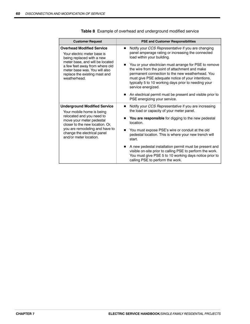
DISCONNECTION AND MODIFICATION OF SERVICE60
ELECTRIC SERVICE HANDBOOK/SINGLE‐FAMILY RESIDENTIAL PROJECTSCHAPTER 7
Table 8 Example of overhead and underground modified service
Customer Request PSE and Customer Responsibilities
Overhead Modified Service
Your electric meter base isbeing replaced with a newmeter base, and will be locateda few feet away from where oldmeter base was. You will alsoreplace the existing mast andweatherhead.
� Notify your CCS Representative if you are changingpanel amperage rating or increasing the connectedload within your building.
� You or your electrician must arrange for PSE to removethe wire from the point of attachment and makepermanent connection to the new weatherhead. Youmust give PSE adequate notice of your intentions,typically 5 to 10 working days prior to needing yourservice energized.
� An electrical permit must be present and visible prior toPSE energizing your service.
Underground Modified Service
Your mobile home is beingrelocated and you need tomove your meter pedestalcloser to the new location. Or,you are remodeling and have tochange the electrical paneland/or meter location.
� Notify your CCS Representative if you are increasingthe load or capacity of your meter panel.
� You are responsible for digging to the new pedestallocation.
� You must expose PSE’s wire or conduit at the oldpedestal location. This is where your new trench willstart.
� A new pedestal installation permit must be present andvisible on-site prior to calling PSE to perform the work.You must give PSE 5 to 10 working days notice prior tocalling PSE to perform the work.
GLOSSARY 61
ELECTRIC SERVICE HANDBOOK/SINGLE‐FAMILY RESIDENTIAL PROJECTS
Glossary
Approved - Acceptable to the authority having jurisdiction.
Backfill - Native soil or soil brought in from another area, free from sharp objects, rocks,scrap building material, and corrosive material.
Clearance - A set distance between two objects.
Conduit - A listed or approved wireway with a smooth interior surface to permit easydrawing-in of the electrical conductors. A conduit may be metallic or nonmetallic,depending on its usage, in accordance with codes and Puget Sound Energy Standards.
Current Transformer (CT) Enclosure - A sealable cabinet designed for surface or flushmounting, and provided with a frame or trim in which doors or removable covers arehung.
Customer Construction Services (CCS) Representative - The designated representativeof Puget Sound Energy, responsible for design and/or coordination of new or revisedservices to PSE customers. The CCS Representative responds to inquiries on policies,standards, practices, rates, and energy utilization.
Demand - The maximum average kilowatt load used by the customer for a specificperiod of time during the billing period.
Direct Burial - The installation of electrical conductors in a trench, without the use ofconduit.
Drip Loop - A loop formed in overhead secondary conductors at the weatherhead toprevent water from entering into the service entrance conduit and equipment.
EUSERC - Electrical Utility Service Equipment Requirements Committee
Guy - Cable or brace used to relieve the strain of overhead conductors on masts andpoles.
Manual Block Bypass (Circuit-Closing Block) - A provision for paralleling the metercircuit, allowing the meter to be removed without interrupting service to the customer.
Meter Jaw - A spring-loaded receptacle installed inside a meter socket, interfacing theterminals of the meter to the source and load conductors of the service.
Meter Loop - Any provision in which an electrical meter may be installed. Does notinclude the service disconnect device.
Meter Pole - A pole which supports the metering equipment owned and maintained bythe customer.
Meter Base/Socket - The mounting device consisting of meter jaws, connectors, andenclosure for accommodating socket-type meters. The mounting device may be either asingle socket or a trough to accommodate more than one mounting unit.
Metering Equipment - Any equipment associated with measuring electric energy.

GLOSSARY62
ELECTRIC SERVICE HANDBOOK/SINGLE‐FAMILY RESIDENTIAL PROJECTS
Municipal or State Inspector - The qualified representative of a city or the Washington State Department of Labor and Industries, who has been authorized bygovernmental agencies to inspect electrical service installations on their behalf.
NEC - National Electrical Code
NESC - National Electrical Safety Code
Neutral - The grounded conductor in a single-phase, three-wire or three-phase, four-wiresystem. The service conductor that is at zero potential to ground.
Point of Attachment (Point of Service) - The point at which Puget Sound Energy’sservice conductors are attached to the customer’s premises by an approved insulatedclevis.
Point of Delivery - The connection point of the meter base, on the customer’s premises,where Puget Sound Energy’s circuit and the customer’s system are interconnected.
RCW - Revised Code of Washington
Seal - The locking device used to secure meter and/or service entrance equipment toassure safety and security for the unit.
Secondary Voltage- The lower voltage, after transformation, used to supply the customerwith electrical energy. Normally less than 600 V.
Self-Contained - In reference to meter sockets: a device designed and rated tocontinuously carry the entire capacity of the service entrance equipment through themeter.
Service Entrance Conductors - Those conductors which extend between the customer’sload center and point of delivery.
Service Entrance Equipment - Service conduit, conductors, weatherhead, meter base,enclosures, service disconnect, and load center.
Service Mast - The conduit above the meter used to provide mechanical protection forthe service conductors and to support the service drop from Puget Sound Energy’ssystem.
Temporary Service - An electrical service installed by Puget Sound Energy to providepower to a customer on a temporary basis (12 months or less).
UL - (Underwriters Laboratories) A nationally recognized test laboratory which listsmaterials it has tested and accepted.
UULC - Utilities Underground Location Center
WAC - Washington Administrative Code

Notes

Notes