Embed Size (px)
Citation preview
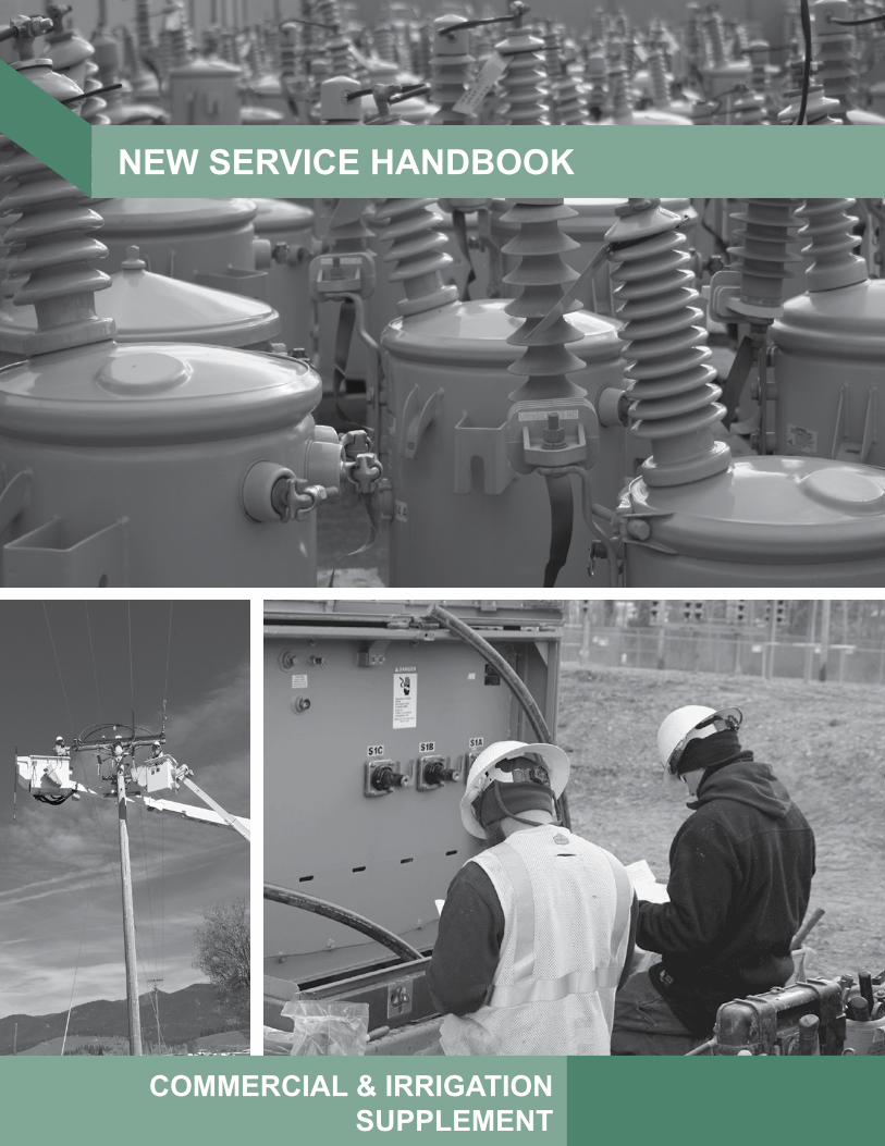
NEW SERVICE HANDBOOK
COMMERCIAL & IRRIGATIONSUPPLEMENT
There are three basic ways to measure electricity consumption:
•Small and medium services are metered directly using direct connect meters. •Large services are metered using current transformers (CTs) and instrument-rated meters. •Very large services are metered at switchboards housing CTs and instrument meters.
The customer provides and installs all equipment to the load side of the point of delivery: meter sockets, cabinets and enclosures, connection lugs, conduit, grounding, protection devices, and wiring from the socket to the load. (Examples: breakers, phase protection, and capacitors.)
MEC provides and installs the meter, current and/or potential transformers, and local wiring associated with the meters and CTs/PTs.
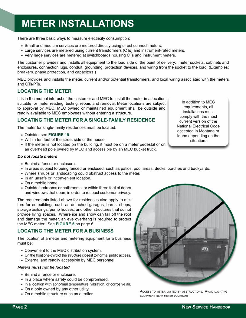
Locating the Meter It is in the mutual interest of the customer and MEC to install the meter in a location suitable for meter reading, testing, repair, and removal. Meter locations are subject to approval by MEC. MEC owned or maintained equipment shall be outside and readily available to MEC employees without entering a structure.
Locating the Meter for a SingLe-faMiLy reSidence The meter for single-family residences must be located:
•Outside see figure 19.•Within ten feet of the street side of the house.• If the meter is not located on the building, it must be on a meter pedestal or on
an overhead pole owned by MEC and accessible by an MEC bucket truck.
Do not locate meters
•Behind a fence or enclosure.• In areas subject to being fenced or enclosed, such as patios, pool areas, decks, porches and backyards. •Where shrubs or landscaping could obstruct access to the meter.• In an unsafe or inconvenient location.•On a mobile home.•Outside bedrooms or bathrooms, or within three feet of doors
and windows that open, in order to respect customer privacy.
The requirements listed above for residences also apply to me-ters for outbuildings such as detached garages, barns, shops, storage buildings, pump houses, and other structures that do not provide living spaces. Where ice and snow can fall off the roof and damage the meter, an eve overhang is required to protect the MEC meter. See figure 5 on page 6.
Locating the Meter for a BuSineSS The location of a meter and metering equipment for a business must be:
•Convenient to the MEC distribution system.• On the front one-third of the structure closest to normal public access. •External and readily accessible by MEC personnel.
Meters must not be located
•Behind a fence or enclosure.• In a place where safety could be compromised.• In a location with abnormal temperature, vibration, or corrosive air.•On a pole owned by any other utility.•On a mobile structure such as a trailer.
PAGE 2 NEW SERVICE HANDBOOK
Access to meter limited by obstructions. Avoid locAting equipment neAr meter locAtions.
In addition to MEC requirements, all installations must
comply with the most current version of the
National Electrical Code accepted in Montana or Idaho depending on the
situation.
Meter inStaLLationS
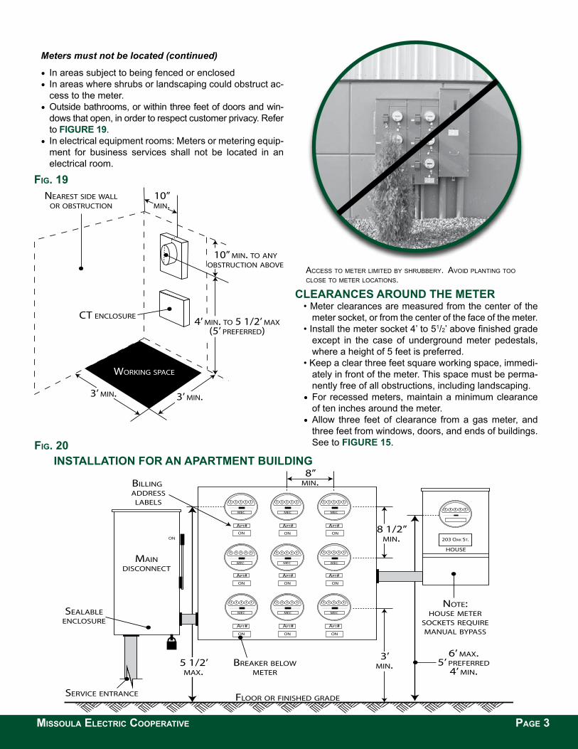
Meters must not be located (continued)
• In areas subject to being fenced or enclosed• In areas where shrubs or landscaping could obstruct ac-
cess to the meter.•Outside bathrooms, or within three feet of doors and win-
dows that open, in order to respect customer privacy. Refer to figure 19.
• In electrical equipment rooms: Meters or metering equip-ment for business services shall not be located in an electrical room.
Access to meter limited by shrubbery. Avoid plAnting too close to meter locAtions.
cLearanceS around the Meter• Meter clearances are measured from the center of the
meter socket, or from the center of the face of the meter. • Install the meter socket 4’ to 51/2’ above finished grade
except in the case of underground meter pedestals, where a height of 5 feet is preferred.
• Keep a clear three feet square working space, immedi-ately in front of the meter. This space must be perma-nently free of all obstructions, including landscaping.
•For recessed meters, maintain a minimum clearance of ten inches around the meter.
•Allow three feet of clearance from a gas meter, and three feet from windows, doors, and ends of buildings. See to figure 15.
WORKING SPACE
NEAREST SIDE WALLOR OBSTRUCTION
3’ MIN. 3’ MIN.
CT ENCLOSURE4’ MIN. TO 5 1/2’ MAX
(5’ PREFERRED)
10” MIN. TO ANYOBSTRUCTION ABOVE
10” MIN.
FIG. 19
8”MIN.
8 1/2”MIN.
3’MIN.5 1/2’
MAX.
SERVICE ENTRANCE
MAINDISCONNECT
BREAKER BELOWMETER
BILLING ADDRESS
LABELS
SEALABLEENCLOSURE
6’ MAX.5’ PREFERRED
4’ MIN.
NOTE:HOUSE METER
SOCKETS REQUIREMANUAL BYPASS
FLOOR OR FINISHED GRADE
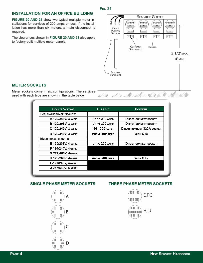
FIG. 20inStaLLation for an apartMent BuiLding
MISSOULA ELECTRIC COOPERATIVE PAGE 3
123456789
410 VINE ST
200
ON
OFF
MEC123456789
408 VINE ST
200
ON
OFF
MEC123456789
414 VINE ST
200
ON
OFF
MEC
BARRIER
5 1/2’ MAX.4’ MIN.
123456789
412 VINE ST
200
ON
OFF
MEC
CABLEPULLINGSECTION
CUSTOMERDISCONNECTS
SEALABLEENCLOSURE
SEALABLE GUTTER
PAGE 4 NEW SERVICE HANDBOOK
A
H,I,J
E,F,G
D
C
B
A
H,I,J
E,F,G
D
C
B
inStaLLation for an office BuiLding figure 20 and 21 show two typical multiple-meter in-stallations for services of 200 amps or less. If the instal-lation has more than six meters, a main disconnect is required.
The clearances shown in figure 20 and 21 also apply to factory-built multiple meter panels.
Meter SocketS Meter sockets come in six configurations. The services used with each type are shown In the table below:
Socket Voltage current comment
SingLe phaSe Meter SocketS three phaSe Meter SocketS
FIG. 21
generaL requireMentS for Meter SocketS Meter sockets must be:
• Residential metering: Ring-type, to accept a meter sealing ring.• Commercial and irrigation metering: Ring-less type with meter bypass lever.• Rated NEMA 3R - for exterior use and rain-tight.• Installed level, plumb, and fastened securely to a rigid structure.• Closed with plugs and secured tightly from the inside if unused.• Covered and sealed with a transparent cover if live (energized) lines are installed.• Not jumpered to provide power.• Acceptable to MEC and Underwriters Laboratories (UL).
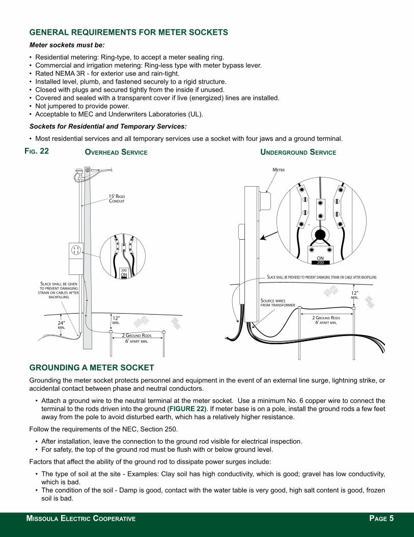
Sockets for Residential and Temporary Services:
• Most residential services and all temporary services use a socket with four jaws and a ground terminal.
OVERHEAD SERVICE UNDERGROUND SERVICE
grounding a Meter Socket Grounding the meter socket protects personnel and equipment in the event of an external line surge, lightning strike, or accidental contact between phase and neutral conductors.
• Attach a ground wire to the neutral terminal at the meter socket. Use a minimum No. 6 copper wire to connect the terminal to the rods driven into the ground (figure 22). If meter base is on a pole, install the ground rods a few feet away from the pole to avoid disturbed earth, which has a relatively higher resistance.
Follow the requirements of the NEC, Section 250.
• After installation, leave the connection to the ground rod visible for electrical inspection. • For safety, the top of the ground rod must be flush with or below ground level.
Factors that affect the ability of the ground rod to dissipate power surges include:
• The type of soil at the site - Examples: Clay soil has high conductivity, which is good; gravel has low conductivity, which is bad.
• The condition of the soil - Damp is good, contact with the water table is very good, high salt content is good, frozen soil is bad.
24”MIN.
2 GROUND RODS
6’ APART MIN.
12”MIN.
15’ RIGIDCONDUIT
SLACK SHALL BE GIVENTO PREVENT DAMAGING
STRAIN ON CABLES AFTER BACKFILLING
200ON
2 GROUND RODS6’ APART MIN.
12”MIN.
200ON
METER
SLACK SHALL BE PROVIDED TO PREVENT DAMAGING STRAIN ON CABLE AFTER BACKFILLING
SOURCE WIRES FROM TRANSFORMER
MISSOULA ELECTRIC COOPERATIVE PAGE 5
FIG. 22
grounding a Meter Socket (continued) • The size of the ground rod - The longer the rod and the larger the diameter, the better. • The ground rod material - Copper is better than steel. Copper-clad steel is better than steel alone. • The resistance across clamps and connections - Note: The integrity of these connections tends to deteriorate with time.
Meter inStaLLation tipS Cable Runs:
• Metered circuits and un-metered circuits must not be intermixed in raceways or enclosures. • Customer equipment or wiring is not allowed inside a meter enclo-
sure or current transformer (CT) cabinet. • Customer load monitoring equipment, if installed, must be con-
nected on the load side with respect to the meter. • Line-side conductors are connected to the top terminals of the me-
ter socket, and load-side conductors are connected to the bottom terminals of the meter socket.
• After the installation is complete, make these mechanical checks: conductors are not under undue strain on their terminals, connec-tions are tight, terminals are rated for the size of conductor used, and strands have not been removed to make conductors fit under-sized terminals.
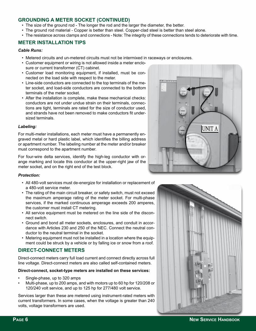
Labeling:
For multi-meter installations, each meter must have a permanently en-graved metal or hard plastic label, which identifies the billing address or apartment number. The labeling number at the meter and/or breaker must correspond to the apartment number.
For four-wire delta services, identify the high-leg conductor with or-ange marking and locate this conductor at the upper-right jaw of the meter socket, and on the right end of the test block.
Protection:
• All 480-volt services must de-energize for installation or replacement of a 480-volt service meter.
• The rating of the main circuit breaker, or safety switch, must not exceed the maximum amperage rating of the meter socket. For multi-phase services, if the marked continuous amperage exceeds 200 amperes, the customer must install CT metering.
• All service equipment must be metered on the line side of the discon-nect switch.
• Ground and bond all meter sockets, enclosures, and conduit in accor-dance with Articles 230 and 250 of the NEC. Connect the neutral con-ductor to the neutral terminal in the socket.
• Metering equipment must not be installed in a location where the equip-ment could be struck by a vehicle or by falling ice or snow from a roof.
direct-connect MeterS Direct-connect meters carry full load current and connect directly across full line voltage. Direct-connect meters are also called self-contained meters.
direct-connect, socket-type meters are installed on these services:
• Single-phase, up to 320 amps• Multi-phase, up to 200 amps, and with motors up to 60 hp for 120/208 or
120/240 volt service, and up to 125 hp for 277/480 volt service.
Services larger than these are metered using instrument-rated meters with current transformers. In some cases, when the voltage is greater than 240 volts, voltage transformers are used.
PAGE 6 NEW SERVICE HANDBOOK
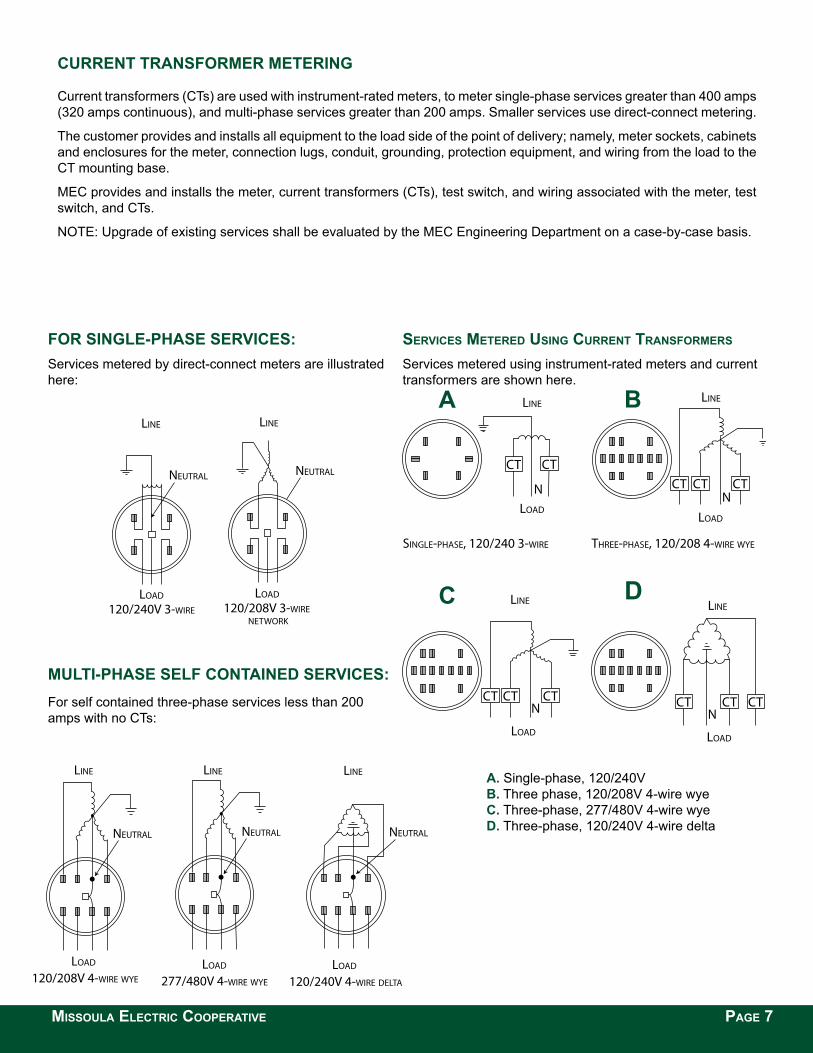
current tranSforMer Metering
Current transformers (CTs) are used with instrument-rated meters, to meter single-phase services greater than 400 amps (320 amps continuous), and multi-phase services greater than 200 amps. Smaller services use direct-connect metering.
The customer provides and installs all equipment to the load side of the point of delivery; namely, meter sockets, cabinets and enclosures for the meter, connection lugs, conduit, grounding, protection equipment, and wiring from the load to the CT mounting base.
MEC provides and installs the meter, current transformers (CTs), test switch, and wiring associated with the meter, test switch, and CTs.
NOTE: Upgrade of existing services shall be evaluated by the MEC Engineering Department on a case-by-case basis.
CT CT CTN
LOAD
LINE
THREE-PHASE, 277/480 4-WIRE WYE
N
LOAD
LINE
THREE-PHASE, 120/240 4-WIRE DELTA
CT CT CT
NLOAD
LINE
THREE-PHASE, 120/208 4-WIRE WYE
CTCTCTNLOAD
LINE
SINGLE-PHASE, 120/240 3-WIRE
CTCT
a. Single-phase, 120/240V B. Three phase, 120/208V 4-wire wye c. Three-phase, 277/480V 4-wire wye d. Three-phase, 120/240V 4-wire delta
SERVICES METERED USING CURRENT TRANSFORMERS
Services metered using instrument-rated meters and current transformers are shown here.
for SingLe-phaSe ServiceS:Services metered by direct-connect meters are illustrated here:
For self contained three-phase services less than 200 amps with no CTs:
B
dc
a
MISSOULA ELECTRIC COOPERATIVE PAGE 7
MuLti-phaSe SeLf contained ServiceS:
277/480V 4-WIRE WYE
NEUTRAL
LOAD
LINE
120/208V 4-WIRE WYE
NEUTRAL
LOAD
LINE
120/240V 4-WIRE DELTA
NEUTRAL
LOAD
LINE
NEUTRAL NEUTRAL
LINE
120/240V 3-WIRE 120/208V 3-WIRE NETWORK
LOAD LOAD
LINE
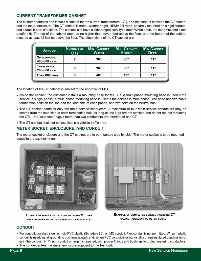
current tranSforMer caBinet The customer obtains and installs a cabinet for the current transformers (CT), and the conduit between the CT cabinet and the meter enclosure. The CT cabinet is metal, weather-tight, NEMA 3R rated, securely mounted on a rigid surface, and plumb in both directions. The cabinet is to have a side-hinged, seal type door. When open, the door must not block a safe exit. The top of the cabinet must be no higher than seven feet above the floor, and the bottom of the cabinet must be at least 12 inches above the floor. The dimensions of the CT cabinet are:
SERVICENUMBER OF
CTS MIN. CABINET
WIDTHMIN. CABINET
HEIGHTMIN.CABINET
DEPTHSINGLE-PHASE, 400-800 AMPS
2 36” 36” 11”
THREE PHASE, 200-800 AMPS
3 36” 36” 11”
OVER 800 AMPS 3 48” 48” 11”
The location of the CT cabinet is subject to the approval of MEC.
• Inside the cabinet, the customer installs a mounting base for the CTs. A multi-phase mounting base is used if the service is single-phase; a multi-phase mounting base is used if the service is multi-phase. The base has two cable termination bolts on the line and the load side of each phase, and two bolts on the neutral bus.
•The CT cabinet contains only the main service conductors. A maximum of four main service conductors may be served from the load side of each termination bolt, as long as the lugs are not stacked and do not restrict mounting the CTs. Use “stair step” lugs if more than two conductors are terminated at a CT.
•The CT cabinet shall not be installed in a vehicle traffic area.
Meter Socket, encLoSure, and conduit The meter socket enclosure and the CT cabinet are to be mounted side by side. The meter socket is to be mounted opposite the cabinet hinge.
ExAMPLE OF COMPLETED SERVICE INCLUDING CT CABINET ADjACENT TO METER SOCKET.
ExAMPLE OF SERVICE INSTALLATION INCLUDING CT CABI-NET AND METER SOCKET WITH TEST SWITCHES IN PLACE.
conduit• For conduit, use rigid steel, or rigid PVC plastic (Schedule 80), or IMC conduit. Flex conduit is not permitted. When metallic
conduit is used, install grounding bushings at each end. When PVC conduit is used, install a green insulated bonding jump-er in the conduit. 1-1/4-inch conduit or larger is required, with proper fittings and bushings to protect metering conductors.
•The conduit enters the meter enclosure adjacent to the test switch. PAGE 8 NEW SERVICE HANDBOOK
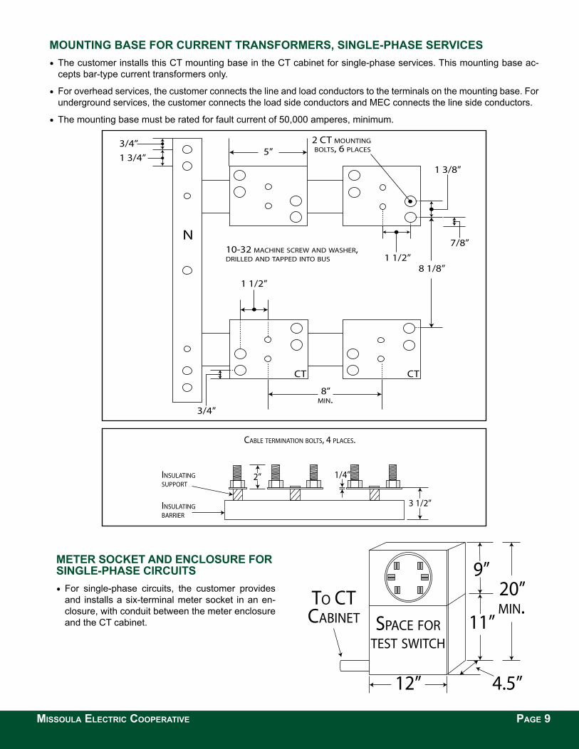
Mounting BaSe for current tranSforMerS, SingLe-phaSe ServiceS •The customer installs this CT mounting base in the CT cabinet for single-phase services. This mounting base ac-
cepts bar-type current transformers only.
•For overhead services, the customer connects the line and load conductors to the terminals on the mounting base. For underground services, the customer connects the load side conductors and MEC connects the line side conductors.
•The mounting base must be rated for fault current of 50,000 amperes, minimum.
5”
1 1/2”
3/4”1 3/4”
8”MIN.
10-32 MACHINE SCREW AND WASHER,DRILLED AND TAPPED INTO BUS
N
CTCT
7/8”
1 1/2”
1 3/8”
8 1/8”
2 CT MOUNTING BOLTS, 6 PLACES
3/4”
1/4”2”
3 1/2”
INSULATINGSUPPORT
INSULATING BARRIER
CABLE TERMINATION BOLTS, 4 PLACES.
9”
11”
20”MIN.
4.5”12”
SPACE FORTEST SWITCH
TO CTCABINET
MISSOULA ELECTRIC COOPERATIVE PAGE 9
Meter Socket and encLoSure for SingLe-phaSe circuitS•For single-phase circuits, the customer provides
and installs a six-terminal meter socket in an en-closure, with conduit between the meter enclosure and the CT cabinet.
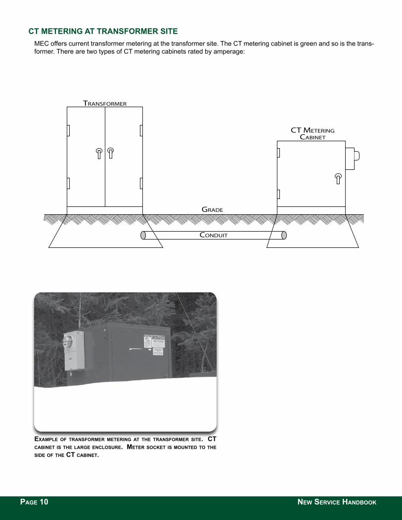
ct Metering at tranSforMer Site MEC offers current transformer metering at the transformer site. The CT metering cabinet is green and so is the trans-former. There are two types of CT metering cabinets rated by amperage:
CT METERING CABINET
TRANSFORMER
GRADE
CONDUIT
ExAMPLE OF TRANSFORMER METERING AT THE TRANSFORMER SITE. CT CABINET IS THE LARGE ENCLOSURE. METER SOCKET IS MOUNTED TO THE SIDE OF THE CT CABINET.
PAGE 10 NEW SERVICE HANDBOOK
MISSOULA ELECTRIC COOPERATIVE PAGE 11
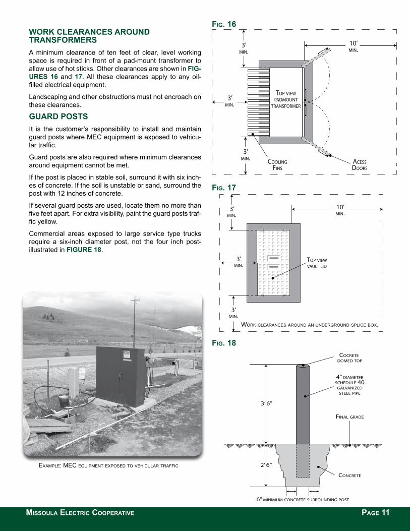
Work cLearanceS around tranSforMerS A minimum clearance of ten feet of clear, level working space is required in front of a pad-mount transformer to allow use of hot sticks. Other clearances are shown in fig-ureS 16 and 17. All these clearances apply to any oil-filled electrical equipment.
Landscaping and other obstructions must not encroach on these clearances.
guard poStSIt is the customer’s responsibility to install and maintain guard posts where MEC equipment is exposed to vehicu-lar traffic.
Guard posts are also required where minimum clearances around equipment cannot be met.
If the post is placed in stable soil, surround it with six inch-es of concrete. If the soil is unstable or sand, surround the post with 12 inches of concrete.
If several guard posts are used, locate them no more than five feet apart. For extra visibility, paint the guard posts traf-fic yellow.
Commercial areas exposed to large service type trucks require a six-inch diameter post, not the four inch post-illustrated in figure 18.
FIG. 16
FIG. 17
3’ 6”
2’ 6”
6” MINIMUM CONCRETE SURROUNDING POST
CONCRETE
FINAL GRADE
COCRETE DOMED TOP
4” DIAMETERSCHEDULE 40
GALVANIZEDSTEEL PIPE
FIG. 18
exAmple: mec equipment exposed to vehiculAr trAffic
10’MIN.
3’MIN.
3’MIN.
3’MIN.
TOP VIEWVAULT LID
10’MIN.
3’MIN.
3’MIN.
3’MIN. ACESS
DOORSCOOLING
FINS
TOP VIEWPADMOUNT
TRANSFORMER
Work cleArAnces Around An underground splice box.
PAGE 12 NEW SERVICE HANDBOOK
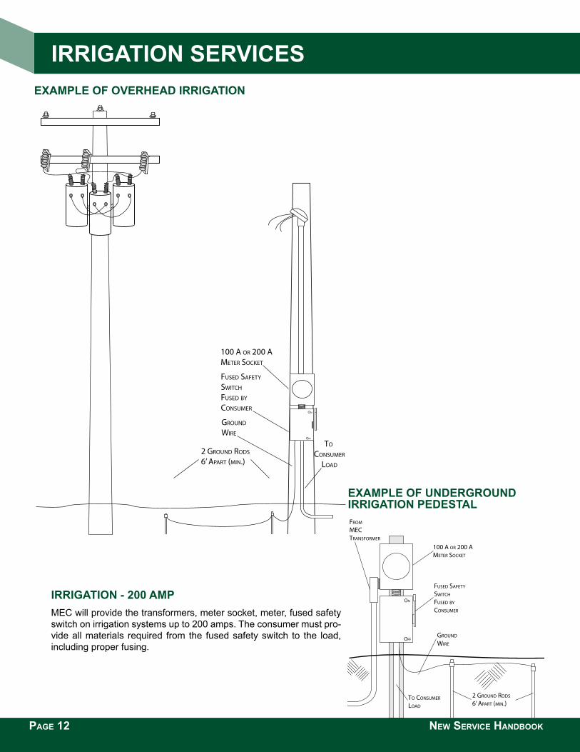
irrigation - 200 aMp MEC will provide the transformers, meter socket, meter, fused safety switch on irrigation systems up to 200 amps. The consumer must pro-vide all materials required from the fused safety switch to the load, including proper fusing.
exaMpLe of overhead irrigation
ON
OFF
100 A OR 200 AMETER SOCKET
FUSED SAFETY SWITCH
FUSED BY CONSUMER
FROM
MECTRANSFORMER
TO CONSUMER
LOAD
2 GROUND RODS
6’ APART (MIN.)
GROUND
WIRE
exaMpLe of underground irrigation pedeStaL
TO CONSUMER
LOAD
2 GROUND RODS
6’ APART (MIN.)
FUSED SAFETY SWITCH
FUSED BY CONSUMER
100 A OR 200 AMETER SOCKET
GROUND
WIRE
ON
OFF
irrigation ServiceS
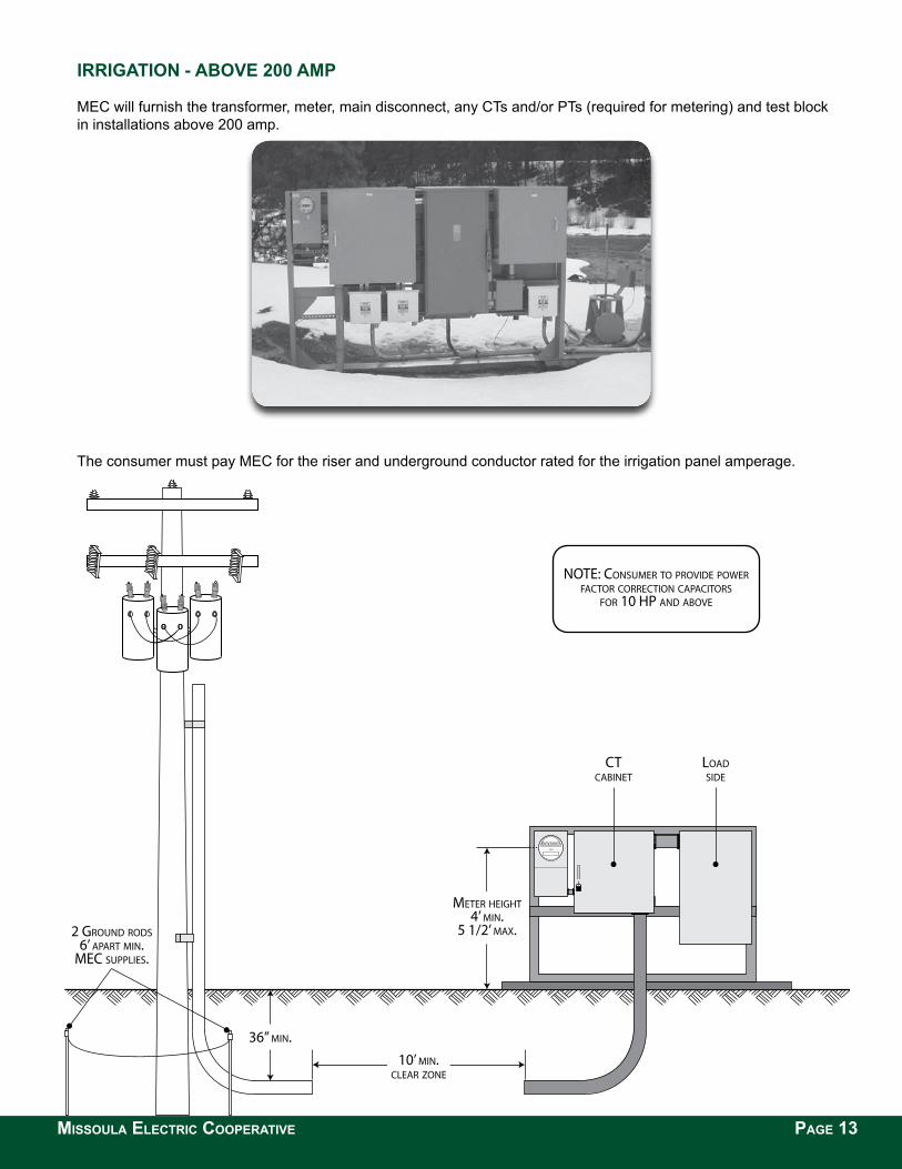
irrigation - aBove 200 aMp
MEC will furnish the transformer, meter, main disconnect, any CTs and/or PTs (required for metering) and test block in installations above 200 amp.
The consumer must pay MEC for the riser and underground conductor rated for the irrigation panel amperage.
LOADSIDE
CTCABINET
NOTE: CONSUMER TO PROVIDE POWERFACTOR CORRECTION CAPACITORS
FOR 10 HP AND ABOVE
METER HEIGHT4’ MIN.
5 1/2’ MAX.
10’ MIN.CLEAR ZONE
36” MIN.
2 GROUND RODS6’ APART MIN.
MEC SUPPLIES.
MISSOULA ELECTRIC COOPERATIVE PAGE 13
GLOSSARy
ANSI - American National Standards Institute. An indepen-dent administrator and coordinator of voluntary industry standards.
Bypass - A device which shunts current around the socket, so the meter can be removed without interrupting service.
Clearance - A specified minimum distance between two ob-jects to assure adequate space for safety, security, or ac-cess.
Common Ground Point - The point where the grounding electrode connects to the equipment-grounding conductor and/or the circuit-grounding conductor.
Conduit - A pipe with a smooth interior surface for easy drawing-in of electrical conductors. Conduit may be metal-lic or nonmetallic.
Corrosion Inhibitor - An electrical joint compound used to retard oxidation at electrical connections.
Current Transformer (CT) - A transformer whose second-ary current is a precise fraction of its primary current. Using current transformers, high-current circuits can be measured with conventional meters.
Demand - The average rate at which energy (kilowatt-hours) is consumed, during a specified interval of time.
Direct-Burial Cable - Cable which may be safely installed in the ground without the protection of a conduit.
Direct-Connect Meter - A meter which carries full load cur-rent and connects across full line voltage. Also called a self-contained meter.
Drip Loop - A downward loop in the customer’s conductors, near where the customer’s conductors attach to the power company’s overhead conductors, to prevent water from en-tering the service mast at the weather-head.
EUSERC - Electric Utility Service Equipment Requirements Committee.
Fault - A partial or total failure of insulation which causes a short circuit between conductors, or between a conductor and ground, causing an abnormal current to flow. Also, a failure (break) in a conductor which causes an open circuit.
Fault Current - A current, which flows between conduc-tors, or between a conductor and ground, due to an abnor-mal connection between the two. A fault current flowing to ground may be called a ground fault current.
Guy - A cable or brace that supports a mast or pole.
High Leg - In a four-wire delta service, the phase with a voltage higher than the other two phases. Also called wild leg, delta leg.
Instrument Transformer - A transformer, which delivers as its output, a precise fraction of the input line current or line voltage. Instrument transformers allow standard meters to measure high currents and voltages.
Instrument-Rated Meter - A meter used in conjunction with instrument transformers to measure high-voltage or high-current services. Also called a transformer-rated meter.
Line Conductor - A service conductor installed by the elec-tric utility, to the meter.
Load Conductor - A service conductor to the customer’s load connected to the load side of the meter.
Load Side - The company-owned side of electric service. See the glossary entry for ‘point of delivery’.
Line Side- The customer-owned side of the electric service. See the glossary entry for ‘point of delivery’.
Manual Link Bypass - Provision for manually installing con-ductive links between the line and load terminals in the meter socket. These links maintain electrical service to the customer when the meter is removed. Also called manual circuit-closing block.
Manufactured Home - A factory-assembled structure built on a permanent chassis, transportable in one or more sec-tions, and designed to be used as a dwelling with a perma-nent foundation. Also called a modular home. New electric service to a manufactured home has the same require-ments as installing new service to a permanent single-fam-ily residence.
MEC - Missoula Electric Cooperative, Inc.
Meter - The first physical device located on the customer’s side of the point of delivery, the customer uses the meter to measure the electric power usage. Although located on the customer side of the point of delivery, the power company owns the meter.
Meter Jaw - A spring-loaded receptacle inside a meter socket, which captures the terminals (blades) of a meter, and connects the meter terminals to the service conductors. Meter Pedestal - A factory-built assembly containing a me-ter socket and disconnect switches.
Meter Ring - A metal ring, which secures the meter to the meter socket, which can be sealed by the electric utility to prevent tampering with the meter.
Meter Socket - the mounting device consisting of meter jaws, connectors, and enclosure for receiving a socket-type meter.
Mobile Home - A factory-assembled structure built on a permanent chassis, transportable in one or more sections, and designed to be used as a dwelling without a perma-nent foundation. A meter pole provides overhead service to a mobile home. A meter pedestal provides underground service to a mobile home.
NEC - National Electrical Code. National regulations for the installation of electrical equipment inside buildings. Pub-lished by the National Fire Protection Association. NEC rules apply to equipment on the customer’s side of the point of delivery.
PAGE 14 NEW SERVICE HANDBOOK
NEMA - National Electrical Manufacturers Association. A trade association which publishes standards for manu-facturers of electrical equipment, including enclosures and racks.
NESC - National Electrical Safety Code. National regula-tions for the installation, operation, and maintenance of electric supply and communication lines. Published by Institute of Electrical and Electronics Engineers. NESC rules apply to equipment on the electric utility’s side of the point of delivery.
NFGC - National Fuel Gas Code.
Neutral - The grounded conductor in a single-phase three-wire, or three-phase four-wire system.
OSHA - Occupational Safety & Health Administration
Point of Attachment - The point at which MEC service conductors are mechanically attached to the customer’s premises. For overhead services, the point of attach-ment is usually an insulated clevis.
Point of Delivery - The ownership boundary point in the electrical service between the power company and the customer. Technically, the meter is located on the cus-tomer’s side of the point of delivery although the power company owns the meter. The company-owned side is often referred to as the ‘line side’ of the meter. The cus-tomer-owned side is often referred to as the ‘load side’ of the meter.
Power Factor - Technically, the cosine of the phase an-gle between the circuit voltage and current waveforms. Since phase angles are difficult to measure, measuring power or impedance usually derives power factor. Pow-er factor is the ratio of active power to apparent power (watts divided by volt-amperes). Power factor has no units, but is commonly expressed as a percentage. For example, if active power is 96 kW and apparent power is 100 kW, the power factor is 96%.
Primary Voltage - The voltage at which electricity is de-livered from substations to distribution transformers. Pri-mary voltage is greater than 600 volts.
Raceway - An enclosed channel for holding wires or ca-bles. If designated for line conductors, the raceway must be able to be sealed. The intermixing of line and load conductors in the same raceway is not permitted.
Seal - A locking device to secure a meter or other service equipment.
Secondary Voltage - The voltage at which electricity is delivered from distribution transformers to customers. Secondary voltage is less than 600 volts.
Select Backfill - Soil or sand free from sharp objects, rocks, scrap building material, and corrosive material.
Self-Contained Meter - A meter which carries full load current and connects directly across full line voltage. Also called a direct-connect meter.
Service Drop - For overhead service, the power com-pany’s service line between the distribution transformer and the point of delivery.
Service Line - Conductors from the distribution trans-former to the customer’s point of delivery. See service drop, service lateral.
Service Entrance Equipment - The service equipment, which is supplied by the customer, namely, conduit, con-ductors, mast, weather-head, meter base, enclosures, disconnects, and panels.
Service Lateral - For underground service, the service line between the distribution transformer and the point of delivery.
Service Mast - For overhead service, the conduit rising above the meter to provide mechanical protection to the customer’s conductors and to support the service drops from the power company.
Socket - The mounting device for socket meters. In-cludes spring-loaded meter jaws, connectors for line and load conductors, and an enclosure.
Temporary Service - Electric service provided by the power company during the construction phase of a proj-ect.
Test Switch - A device used to isolate connections to a meter from the meter’s instrument transformers.
Transformer-Rated Meter - A meter used in conjunction with instrument transformers, to measure high-voltage or high-current services. Also called an instrument-rated meter.
UL - Underwriters Laboratories. An independent prod-uct-testing and certification organization.
Voltage Transformer - (VT, or PT for potential transform-er) A transformer whose secondary voltage is a precise fraction of its primary voltage. Using voltage transform-ers, high-voltage circuits can be measured with conven-tional meters.
MISSOULA ELECTRIC COOPERATIVE PAGE 15

R
1700 W. BROADWAy MISSOULA, MT 59808 PH. 406-541-4433 800-352-5200 FAx 406-541-6318 www.missoulaelectric.com