Embed Size (px)
Citation preview

EGRR01
Electric Gripper Solutions
Series EGRRElectric High Capacity Gripper
Built on the field proven Series GRR chassis, the electric version offers many of the same benefits as the pneumatic. Plus, you receive the design flexibility of Your Motor, Your Way features.
2
www.phdinc.com/egrr • (800) 624-8511EGRR01
Major Benefits
• Servomotorcontrolprovidesacceleration,velocity,andpositionfeedback.
• Compactdesignprovideshighgripforce,largemomentcapacities,longjawtravel,andlowoverallweightforapplicationswithlimitedspace.
• Ruggedconstructionwithstandshighimpactandshockloadsindemandingindustrialenvironments.
• Threelargediameterjawguidesspanningthelengthofthegripperprovidestablejawtravel,longallowabletoolinglength,andhighmomentcapacities.
• Robustrackandpinionjawdriveprovidesrepeatablejawpositioning.
• Your Motor, Your Wayallowsmotorandcontrolsflexibilityatnoadditionalcost.
• OptionalPHD-suppliedKollmorgen®motormatchesperformanceofpopularpneumaticSeriesGRRGuardian®Gripper.
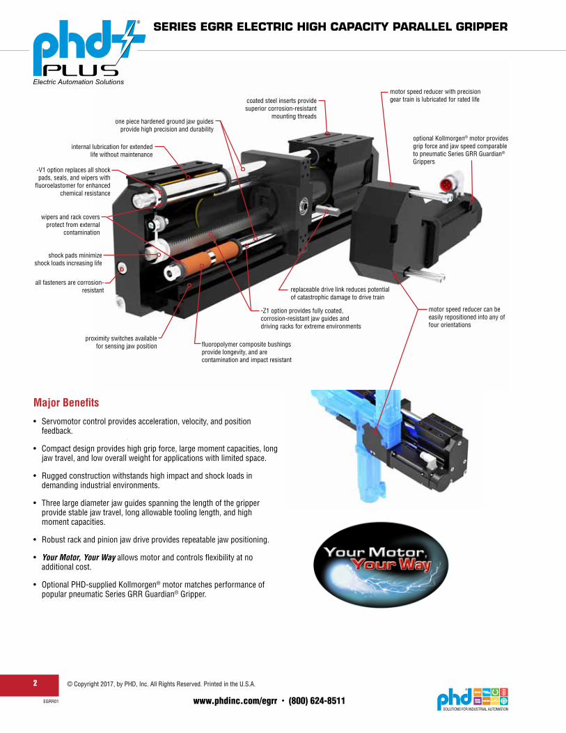
coatedsteelinsertsprovidesuperiorcorrosion-resistant
mountingthreads
motorspeedreducerwithprecisiongeartrainislubricatedforratedlife
optionalKollmorgen®motorprovidesgripforceandjawspeedcomparabletopneumaticSeriesGRRGuardian®Grippers
motorspeedreducercanbeeasilyrepositionedintoanyoffourorientations
proximityswitchesavailableforsensingjawposition fluoropolymercompositebushings
providelongevity,andarecontaminationandimpactresistant
-Z1optionprovidesfullycoated,corrosion-resistantjawguidesanddrivingracksforextremeenvironments
replaceabledrivelinkreducespotentialofcatastrophicdamagetodrivetrain
shockpadsminimizeshockloadsincreasinglife
allfastenersarecorrosion-resistant
-V1optionreplacesallshockpads,seals,andwiperswithfluoroelastomerforenhanced
chemicalresistance
wipersandrackcoversprotectfromexternal
contamination
internallubricationforextendedlifewithoutmaintenance
onepiecehardenedgroundjawguidesprovidehighprecisionanddurability
SERIES EGRR ELECTRIC HIGH CAPACITY PARALLEL GRIPPER
©Copyright2017,byPHD,Inc.AllRightsReserved.PrintedintheU.S.A.

3
www.phdinc.com/egrr • (800) 624-8511 EGRR01
Greenshadedareasindicateoptionsandareincludedinorderingcode.
Blueshadedareasindicateaccessoriesandareorderedbykitorpartnumbers.
MOUNTING OPTIONS & ACCESSORIES
NOTE:DesignNumberdictatesimperialormetricmountings.Dowelpinholesaremetricregardlessofdesignnumber.
PROXIMITYSWITCHES,BRACKETS,AND
TARGETKITS
INCLUDESMOTORMOUNTINGFASTENERS
INCLUDESMOTORMOUNTINGFASTENERS-W0174
-RW151
-Wxxxx
-W0000
-M1095
-Z1
-V1
Options must be ordered together
ORDERING DATA: SERIES EGRR ELECTRIC HIGH CAPACITY GRIPPER
Example Ordering Data:
E G R R 1 2 - 5 - 63 x 200 - V1-Z1 - RW151 - Wxxxx - Mxxxx
Electromechanical
Gripper
Regular Duty
Long Travel, High Capacity Parallel Gripper
Synchronized, Standard Grip
Jaw Style 2
Design No.5 - Metric1 - Imperial
See Note
Size Jaw Travel OptionsV1 - Fluoroelastomer seals and wipersZ1 - Fully corrosion-
resistant coating on jaw guides and drive racks.
NOTE: Fasteners are corrosion resistant as standard
15:1 Motor Speed Reducer
Motor Mounting CodeW0174 - Direct mounting
for Kollmorgen® AKM33H-AND2CA00
Wxxxx - Open architecture part number code (configure code online)
W0000 - Blank Motor Mounting
Motor Code(requires RW151-W1095)M1095 - PHD-supplied
Kollmorgen® AKM33H-AND2CA00 (performance comparable to PHD Series GRR Gripper)
No Code - No Motor
mm150200250300350
in5.9067.8749.843
11.81113.780
OPEN POSITION
CLOSED POSITION
TOTAL JAW TRAVEL = OPEN POSITION - CLOSED POSITION
(Home positioning mayreduce usable travel)

4
www.phdinc.com/egrr • (800) 624-8511EGRR01
ENGINEERING DATA: SERIES EGRR ELECTRIC HIGH CAPACITY GRIPPER
MODEL NUMBER
TOTAL JAW TRAVELTRAVEL TOLERANCE
GRIPPER WEIGHT FULL TRAVERSE
TIME FACTOR**
GRIP FORCE FACTOR GF*WITHOUT MOTOR
SPEED REDUCERWITH MOTOR
SPEED REDUCERWITH REDUCER
& M1095 MOTOR+4.8+2.1
+ 0.189+ 0.084
mm in kg lb kg lb kg lb CF METRIC IMPERIALEGRR12-x-63 x 150 150 5.906 12.8 28.2 14.9 32.8 18.3 40.2 1057
937 23.8EGRR12-x-63 x 200 200 7.874 15.3 33.7 17.4 38.3 20.8 45.7 1410EGRR12-x-63 x 250 250 9.843 18.2 40.1 20.3 44.7 23.7 52.1 1762EGRR12-x-63 x 300 300 11.811 20.5 45.1 22.5 49.7 25.9 57.1 2115EGRR12-x-63 x 350 350 13.780 22.7 50.1 24.8 54.7 28.2 62.1 2467
* Grip force varies with tooling length**Time factors assume a total jaw acceleration and deceleration of 1G (0.5 G per jaw) to and from jaw running speed
MAXIMUM ALLOWABLE FORCES AND MOMENTS
MODEL NUMBERFa Mx My Mz
N lb Nm in-lb Nm in-lb Nm in-lbEGRR-12-x-63x150 15570 3500 880 8000 715 6500 715 6500EGRR-12-x-63x200 15570 3500 990 9000 825 7500 825 7500EGRR-12-x-63x250 15570 3500 990 9000 825 7500 825 7500EGRR-12-x-63x300 15570 3500 990 9000 825 7500 825 7500EGRR-12-x-63x350 15570 3500 990 9000 825 7500 825 7500
Fa: Total for both jawsMx: Allowable moment per jaw, measured from jaw mounting surfaceMy: Allowable moment per jaw, measured from geometric center of jawMz: Allowable moment per jaw, measured from jaw mounting surface
When calculating the value for Fa, include weight of tooling, part weight, acceleration, and external forces. When calculating values for Mx, My, and Mz, include the grip force per jaw, part weight, external forces, and acceleration as applicable.
My
Mx
Fa
Mz
SPECIFICATIONS SERIES EGRRINPUT TORQUE Without Motor Speed Reducer 2.9 Nm min to 43.2 Nm max [26 in-lb min to 382 in-lb max] With RW151 Motor Speed Reducer 0.3 Nm min to 3.8 Nm max [2.3 in-lb min to 34 in-lb max]INPUT RUNNING SPEED Without Motor Speed Reducer 400 rpm max With RW151 Motor Speed Reducer 6000 rpm maxJAW GRIP SPEED* 50 mm/sec max [2 in/s max]OPERATING TEMPERATURE -28° to +82° C [-20° to 180° F]RATED LIFE 5 million cycles minimumGRIP REPEATABILITY Within 0.05 mm [.002 inch] of original centered positionLUBRICATION Factory lubricated for rated lifeMAINTENANCE Field repairable (except reducer)
* Jaw grip speed is speed which jaws contact gripped workpiece. Jaws may operate at faster speeds, but must decelerate to grip speed prior to grip.
MODEL NUMBER
JAW TRAVEL FACTOR JTJAW TRAVEL DIRECTION
TRAVEL DIRECTION WITH SPECIFED INPUT SHAFT ROTATION
WITHOUT MOTOR SPEED REDUCER
WITH RW151 MOTOR SPEED REDUCER
WITHOUT MOTOR SPEED REDUCER
WITH RW151 MOTOR SPEED REDUCER
METRIC IMPERIAL METRIC IMPERIAL CW CCW CW CCW
EGRR12-x-63 x 150
127.674 5.027 8.512 0.335 Open Close Close OpenEGRR12-x-63 x 200EGRR12-x-63 x 250EGRR12-x-63 x 300EGRR12-x-63 x 350
MOMENT VALUES ASSUME THE USE OF ALL THREADED MOUNTING HOLES.

5
www.phdinc.com/egrr • (800) 624-8511 EGRR01
ENGINEERING DATA: SERIES EGRR ELECTRIC HIGH CAPACITY GRIPPER ENGINEERING DATA: SERIES EGRR ELECTRIC HIGH CAPACITY GRIPPER
0.70
0.75
0.80
0.85
0.90
0.95
1.00
TOO
LIN
G L
EN
GTH
FA
CTO
R
TOOLING LENGTH mm [in]
TOOLING LENGTH DERATING FACTOR
0 50 100 150 200 250 300 350 400 450 500 [2] [4] [6] [8] [10] [12] [14] [16] [18] [20]
350 mm
300 mm250 mm
200 mm
150 mm
GRIP FORCETotalgrippingforcerelativetotoolinglengthisshownbelowat
thestatedtorqueappliedtothemotorspeedreducerinputshaft.Gripforceperjawequalsthetotalgripforcedividedbytwo.Thegraphsalsoindicatethemaximumtoolinglengthandmaximumratedgripforceforeachgrippersize.
TOTA
L G
RIP
FO
RCE N
[lb
]
TOOLING LENGTH mm [in] TOOLING LENGTH mm [in]
150 mm TRAVEL
TOTA
L G
RIP
FO
RCE N
[lb
] 200 mm TRAVEL
TOTA
L G
RIP
FO
RCE N
[lb
] 250 mm TRAVEL TO
TAL
GR
IP F
OR
CE N
[lb
] 300 mm TRAVEL
TOTA
L G
RIP
FO
RCE N
[lb
]
350 mm TRAVEL
3.8 Nm [34 in-lb]* 3.4 Nm [30 in-lb]2.3 Nm [20 in-lb]
0 50 100 150 200 250 300 350 400 450 500 [2] [4] [6] [8] [10] [12] [14] [16] [18] [20]
0 50 100 150 200 250 300 350 400 450 500 [2] [4] [6] [8] [10] [12] [14] [16] [18] [20]
TOOLING LENGTH mm [in] TOOLING LENGTH mm [in]
0 50 100 150 200 250 300 350 400 450 500 [2] [4] [6] [8] [10] [12] [14] [16] [18] [20]
TOOLING LENGTH mm [in]
0 50 100 150 200 250 300 350 400 450 500 [2] [4] [6] [8] [10] [12] [14] [16] [18] [20]
0 50 100 150 200 250 300 350 400 450 500 [2] [4] [6] [8] [10] [12] [14] [16] [18] [20]
3559 [800]
3114 [700]
2669 [600]
2224 [500]
1770 [400]
1334 [300]
3559 [800]
3114 [700]
2669 [600]
2224 [500]
1770 [400]
1334 [300]
3559 [800]
3114 [700]
2669 [600]
2224 [500]
1770 [400]
1334 [300]
3559 [800]
3114 [700]
2669 [600]
2224 [500]
1770 [400]
1334 [300]
3559 [800]
3114 [700]
2669 [600]
2224 [500]
1770 [400]
1334 [300]
*Maximum rated performance
PARTF/2
F = TOTAL GRIP FORCE
F/2
Tooling Length
Jaw Surface
TOOLING LENGTH FACTORJawtoolingshouldbedesignedsothatthegrippointisas
closetothejawsurfaceaspossible.Asthegrippointismovedawayfromthejawsurface,theappliedmomentcausesjawfrictiontoincrease,resultinginreducedeffectivegripforce.Thegripforcefactor(GF)valuesgiveninthetableaboveareforzerotoolinglength(jawsurface).
Themaximumloadthatgripperscanhandlewillvarybasedon:sizeofthepartbeingpickedup,shapeofthepart,textureofthepart,speedatwhichthepartistransferred,shapeofthefingers,etc.PHDrecommendsthatthefingersofjawsbetooledormachinedtoconformtotheshapeofthepartbeinggripped.

6
www.phdinc.com/egrr • (800) 624-8511EGRR01
ENGINEERING DATA: SERIES EGRR ELECTRIC HIGH CAPACITY GRIPPER
PARTF/2
F = TOTAL GRIP FORCE
F/2
Tooling Length
Jaw Surface
GRIP FORCE EqUATIONS:METRIC: TOTALGRIPFORCE(N)=(Torque[Nm]xGF)xToolingLengthFactor
IMPERIAL: TOTALGRIPFORCE(lb)=(Torque[in-lb]xGF)xToolingLengthFactor
JAW TRAVEL EqUATIONS:Thejawtravelequationrelatestherotationofthegripperormotorspeedreducerinputshafttothelineartravelofthejaws.
METRIC: TOTALJAWTRAVEL(mm)=InputShaftRotation(rev)xJT
IMPERIAL: TOTALJAWTRAVEL(in)=InputShaftRotation(rev)xJT
GRIP FORCE CALCULATION EXAMPLE:
Gripper: SeriesEGRRSize63x200Common Parameters: Input Torque = 3.4Nm[30in-lb] Tooling Length=254mm[10in]
1. Determine Grip Force Factor GF = 937[23.8](fromtableonpage4)
2. Determine Tooling Length Factor = 0.84[0.84](fromToolingLengthFactorgraphonpage4)
3. Total Grip Force Calculations:
For Standard Unit:EGRR12-5-63x200[EGRR12-1-63x200]
Total Grip Force= 3.4Nmx937x0.84=2676N[30in-lbx23.8x0.84=600lb]
JAW TRAVEL CALCULATION EXAMPLE:Gripper: SeriesEGRRSize63x200-RW151-W0000
Common Parameters:
Motor Rotation =2rev
1. Determine Jaw Travel Factor JT =8.512[0.335](fromtableonpage4)
2. Jaw Travel Calculations:
For Standard Unit:EGRR12-5-63x200-RW151-W0000[EGRR12-1-63x200-RW151-W0000]
Total Jaw Travel = 2revx8.512=17.024mm[2revx0.335=0.670in]
FULL TRAVERSE TIMEFulltraversetimeistheshortesttimepossibleforthejawstocompletelytraversethetotaltravelofthegripper.UsePHDSizingSoftwaretocalculatethemotiontimeforyourspecificmotionprofile.Fulltraversetimeassumesthatthejawsareacceleratedat1G(0.5Gperjaw)uptothemotorrunningspeed,thentravelatthemotorrunningspeeduntildeceleratedat1G(0.5Gperjaw)torest.
FULL TRAVERSE TIME EqUATION:TIME (sec) = [CF1 ÷ Running Speed (rpm)] + [Running speed (rpm) ÷ 69120]
FULL TRAVERSE TIME CALCULATION EXAMPLE: Gripper: SeriesEGRRSize63x200
Common Parameters:
Motor Running Speed =5500rpm
1. Determine Time Factors:
CF =1410(fromtableonpage4)
2. Release Time Calculations:
For Standard Unit:EGRR12-5-63x200[EGRR12-1-63x200]
Open or Close Time = [1410÷5500rpm]+[5500rpm÷69120]=0.336sec
Series EGRR Sizing Software
Engineeringrequirements,conceptanddetaildesign
phdinc.com/sizing
1000 2000 3000 4000 5000 6000
3.0
2.5
2.0
1.5
1.0
0.5
0.0
MOTOR RUNNING SPEED (rpm)
FULL TRAVERSE TIMEFU
LL T
RAVERSE
TIM
E (sec)
200 mm
150 mm
350 mm
300 mm
250 mm
-M1095 Motor

7
www.phdinc.com/egrr • (800) 624-8511 EGRR01
ENGINEERING DATA: SERIES EGRR ELECTRIC HIGH CAPACITY GRIPPER DIMENSIONS: SERIES EGRR ELECTRIC HIGH CAPACITY GRIPPER
K2B1
J4J5
J1
J9
2X
209.8 [8.260]
159.0 [6.260]
108.2 [4.260]
60.0[2.3620]
45.0[1.773]
88.9[3.500]
4X Ø 8.0 x 19.0 DP (H7)[0.31525 +0.00030/-0.00030 x 0.750 DP]
DOWEL PIN HOLE
10X MANUFACTURING HOLES (CONSULT PHD FOR MORE INFORMATION)16X M8 x 1.25 x 19.0 DP
[3/8-16 x 0.750 DP](THREADED INSERTS)
92.2[3.630]
127.0[5.000]
89.0[3.504] 61.5
[2.420]
25.4[1.000]
8X M6 x 1-6H DP 16.0 [0.630] MIN 13.0
[0.512]
FOR PROXIMITY SWITCH MOUNTING, SEE ACCESSORIES SECTION FOR DIMENSIONS
25.1[0.990]44.2
[1.740]
JAW DRIVE SOCKETSEE DETAIL FOR DIMENSIONS
2.9[0.113]
58.7[2.311]
90[3.543]
161.9 [6.375]
158.8[6.250]
92.2[3.630]
88.9[3.500]
Ø 13.00 ± 0.013Ø [0.5118 ±0.0005]DRIVE LOCATING BOSS
DRIVE SOCKET10.03 MIN HEX x 19.0 DP
[0.3949 MIN HEX x 0.750 DP]
DRIVE LOCATING BOSS USED TO LOCATE MATING DRIVE ELEMENTS TO GRIPPER
8X M12 x 1.75 x 25.0 DP[1/2-13 x 1.000 DP] THD
(THREADED INSERTS)
Ø 25.4 [1.000](PRIMARY JAW GUIDE)
60.0[2.362]
Ø 13.5 h8[Ø 0.5310 ± 0.0005]
2X Ø 19.1 [0.750](SECONDARY JAW GUIDE)
4X Ø 12.0 x 15.9 DP (H7)[0.47295 +0.00040/-0.00030 x 0.625 DP]DOWEL PIN HOLE
2X MANUFACTURING HOLES(CONSULT PHD FOR MORE INFORMATION)
A OPEN*A CLOSED*
DETAIL
MOMENT CAPABILITY REQUIRES USE OF ALL THREADED MOUNTING HOLES
3
1
4 2
5
6
LETTER DIM
TOTAL JAW TRAVEL150 200 250 300 350
mm in mm in mm in mm in mm inMIN.TRAVELPERJAW 75.0 2.953 100.0 3.937 125.0 4.921 150.0 5.906 175.0 6.890
ACLOSED* 120.0 4.724 139.8 5.504 139.8 5.504 280.0 11.024 330.0 12.992AOPEN* 270.0 10.630 339.8 13.379 389.8 15.347 580.0 22.835 680.0 26.772
B1 439.8 17.314 539.8 21.251 660.8 26.016 760.8 29.953 860.8 33.890J1 105.1 4.136 130.0 5.120 165.6 6.518 190.6 7.504 215.6 8.487J4 66.0 2.598 90.0 3.544 90.0 3.544 90.0 3.544 90.0 3.544J5 33.0 1.299 45.0 1.772 45.0 1.772 45.0 1.772 45.0 1.772J9 47.0 1.850 56.9 2.240 56.9 2.240 127.0 5.000 152.0 5.984K2 320.0 12.598 380.0 14.960 380.0 14.960 590.0 23.228 590.0 23.228
NOTES:1) DESIGNATED ISCENTERLINEOFUNIT2) ALLDIMENSIONSAREREFERENCEONLY
UNLESSSPECIFICALLYTOLERANCED3) IMPERIALINFORMATIONSHOWNIN[]
ORSHOWNINCOLUMNSDESIGNATEDin4) NUMBERSIN INDICATEPOSITIONS5)*AOPENREFLECTSTHESMALLEST
POSSIBLEOPENDIMENSION*ACLOSEDREFLECTSTHELARGEST
POSSIBLECLOSEDDIMENSION

8
www.phdinc.com/egrr • (800) 624-8511EGRR01
OPTIONS: SERIES EGRR ELECTRIC HIGH CAPACITY GRIPPER
OPTION
MMA MMB MMC SqUARESTANDARD OVERSIZED STANDARD OVERSIZED STANDARD OVERSIZEDmm in mm in mm in mm in mm in mm in
W0174 93.6 3.685 — — 15.5 .610 — — 70.0 2.756 — —Wxxxx* 93.6 3.685 111.6 4.394 11.0MIN .433MIN 11.0MIN .433MIN 88.0 3.465 130 5.118W0000 93.6 3.685 — — 22.6 .890 — — 88.0 3.465 — —
Z1
RW151
V1CORROSION-RESISTANT
MOTOR SPEED REDUCER
FLUORO-ELASTOMER SEALS
Corrosion-resistantcoatingonjawguidesanddriveracksprovidesenhancedenvironmentalprotection.
A15:1driveratiomotorspeedreducerisinstalledontothegripper.Thereducerisfactorylubricatedfortheratedlifeofthegripper.Themotorspeedreducerprovidesaconvenientmeansofmatchingtheoutputtorqueandshaftspeedofmanymotorstotheinputrequirementsofthegripper.
Thereducermustbeorderedwithamotormountingcode.Seepage9fordetails.
Motormountingfastenersandmotorcouplingaresuppliedunassembledalongwithassemblyinstructions.
Use-W0174motormountcodetoprovidetheproperinterfaceforusewithaPHD-suppliedKollmorgen®motorwhenoption-M1095isspecified.
Use-W0000motormountcodetoorderamotormountintendedforcustomermodification.Seepage3.
Thereducercanbeeasilyremovedfromthegripperforeaseofmotorinstallationandfieldrotatedintooneoffourpositions.
Fluoro-elastomershockpads,seals,andwipersareavailabletoachievematerialcompatibilitywithcertainfluids.Materialcompatibilityshouldbecheckedwiththefluidmanufacturerforproperapplication.ThisoptionincludesSeriesGRR-V9fluoro-elastomersealsandjawguidewipersoption.
44.5[1.750]
FIELD SELECTABLE REDUCER ORIENTATIONS
MMC SQ VARIES WITH MOTOR
3 1
MMA VARIES WITH MOTOR
27.0 [1.063]
DRIVE LINK BETWEEN GRIPPER AND REDUCER
4
5
2
MMB VARIES WITH MOTOR
73.0[2.875]
ROTATE ABOUT THIS POINT FOR ALTERNATE REDUCER ORIENTATIONS
6
49.2 [1.938]
49.2 [1.938]
REMOVE BOLTS 4 PLACES TO ROTATE REDUCER INTO NEW ORIENTATION
76.2[3.000]
92.2[3.630]
49.2[1.938]
6.5[0.255]
TOP OF REDUCER WHEN ROTATED 180°. DOES NOT INCLUDE MOTOR MOUNTING PLATE
NOTES:1)ALLDIMENSIONSARESHOWNINmm[in]ANDAREREFERENCEONLYUNLESSSPECIFICALLYTOLERANCED2) OPTIONWxxxxMUSTBEORDEREDWITHOPTIONRW1513) REDUCERISSUPPLIEDPREASSEMBLEDINORIENTATIONSHOWN,CUSTOMERMAYROTATEINTOPREFERREDORIENTATION
AFTERRECEIPT4) WHEN(-W0000)ISSPECIFIED,COUPLERISSUPPLIEDWITHUNFINISHEDSHAFTBOREANDMOTORMOUNTINGPLATEIS
SUPPLIEDWITHDIMENSIONSSHOWNWITHOUTMOTORMOUNTINGFASTENERS5) *WxxxxCONFIGUREDONLINE

9
www.phdinc.com/egrr • (800) 624-8511 EGRR01
OPTIONS: SERIES EGRR ELECTRIC HIGH CAPACITY GRIPPER OPTIONS: SERIES EGRR ELECTRIC HIGH CAPACITY GRIPPER
Wxxxx MOTOR MOUNT CODE
Step 1 - Online Actuator Sizing size.phdinc.com • Inputyourapplicationdata.• Thesizingsoftwarewilltellyouwhichgripperandmotor
performanceparametersareneededforyourapplication.
Step 2 - Motor Selection• Basedontheperformancerequirementsdeterminedbyonlinesizing,
selectanappropriatemotorfromyourpreferredmotormanufacturer.• Returntotheonlinesizingsoftwarewithidentifiedmotorparameterstoverify
motortoapplicationcompatibility.
Step 3 - Your Motor, Your Way Configurator config.phdinc.com • Selectyourmotorfromthedropdownmenusorenterthenecessarymotor
geometry.• Thegeneratedmotormountcodeforthecompatiblemotorwillcompletethe
orderingdatanecessarytoorderthegrippertailoredtoyourspecificapplication.• 3DCADmodelsarealsoavailable.• Ifablankmotormountisdesiredforspecialmotorrequirements,use
-W0000toorderamotormountintendedforcustomermodification.
MOTOR GEOMETRY
Your Motor, Your WaycustomizablemotormountingisgeneratedbyPHD’sextensivemotordatabaseatwww.config.phdinc.com.Usersmayselecttheircompatiblemotorofchoicefromthepre-populatedmotordatabase.Intheeventthechosenmotorisnotinthedatabase,theymayenternecessarymotorfeaturestogeneratethePHDmotormountcode.
Thetailoredmotormountingcomponentsareincludedwiththegripperandshippedinkitform.Seepage8for-Wxxxxoptionsanddimensions.
phdplus.phdinc.com
FLANGE WIDTHBOLT HOLECIRCLE
SPECIFY FROM MOTOR:• MOUNTING FASTENER SIZE• THRU HOLE OR THREAD WITH
MINIMUM THREAD DEPTH
FLANGE THICKNESS
SHAFT EXTENSION FROMMOUNTING FACE
OVERALL LENGTH:PRIMARY AND SECONDARYMOTOR PILOT
PRIMARYMOTORPILOT
SECONDARYMOTORPILOT
SPECIFY FROM MOTOR:• MOTOR SHAFT DIAMETER (MAX. DIA IS 19.0 mm [0.750 in])• SHAFT TYPE
NOTES:1)ALLDIMENSIONSAREREFERENCEONLYUNLESS
SPECIFICALLYTOLERANCED2) MOTORMOUNTISSUPPLIEDPREASSEMBLEDTOMOTOR
SPEEDREDUCERANDINCLUDESINSTRUCTIONSANDALLPARTSNECESSARYTOINSTALLMOTOR

10
www.phdinc.com/egrr • (800) 624-8511EGRR01
OPTIONS: SERIES EGRR ELECTRIC HIGH CAPACITY GRIPPER
M1095Factory-installedKollmorgen®AKM33H-AND2CA00motorusedwith
asuitableKollmorgen®motorcontrollerandRW151motorspeedreducerprovidesgripforcesandjawspeedscomparabletoPHD’spneumaticSeriesGRRGuardian®gripper.Thisoptionrequiresoptions-RW151 -W0174.
Themotormaybefieldrotatedtoindexlocationofmotorconnector.
KOLLMORGEN® MOTOR
NOTES:1)ALLDIMENSIONSARESHOWNINmm[in]ANDAREREFERENCE
ONLYUNLESSSPECIFICALLYTOLERANCED2) MOTORSPEEDREDUCERANDMOTORARESUPPLIED
PREASSEMBLEDINORIENTATIONSSHOWN,CUSTOMERMAYROTATEINTOPREFERREDORIENTATIONSAFTERRECEIPT
3) WEIGHTOFMOTOR3.36kg[7.4lb]INCLUDINGMOTORBRAKE
1
REDUCER ROTATED 180°
-M1095 OPTION-M1095 OPTION
3 1 4
5
2
6
76.2[3.000]
92.2[3.630]
49.2[1.938]
6.5[0.255]
TOP OF REDUCER WHEN ROTATED 180°. DOES NOT INCLUDE MOTOR MOUNTING FLANGE
ROTATE ABOUT THIS POINT FOR ALTERNATE
REDUCER ORIENTATIONS
93.6[3.685]
120.6[4.748]
70.0[2.756]
SQUARE SIZE
44.5[1.750]
15.5[0.610]
73.0[2.875]
291.8[11.489]
49.2[1.938]
49.2[1.938]
REMOVE 4 BOLTS FOR SIMPLE ROTATION OF REDUCER TO ANY OF 4 ORIENTATIONS
ACCESSORIES:DRIVE LINK
Asingledrivelinkcouplestheoutputofthemotorspeedreducertotheinputsocketofthegripper.Thelinkisintendedtomechanicallyfailreducingcatastrophicdamagetothegripperandmotorspeedreducerifmaximumtorqueisexceeded.
DRIVE LINK KITPART NUMBER DESCRIPTION88157-0000 UsedwithStandardMotorMountingFlange88157-0018 UsedwithOversizeMotorMountingFlange
Kitincludesonedrivelinkandinstallationinstructions
Contact PHD to purchase associated motor drives and cables.
PERFORMANCE WITH M1095 MOTOR OPTION
MODEL NUMBERFULL TRAVERSE
TIMEMAXIMUM GRIP
FORCE*sec N lb
EGRR12-x-63x150 0.27
3600 809EGRR12-x-63x200 0.34EGRR12-x-63x250 0.40EGRR12-x-63x300 0.46EGRR12-x-63x350 0.53*Gripforceatzerotoolinglength

11
www.phdinc.com/egrr • (800) 624-8511 EGRR01
NOTES:1)ALLDIMENSIONSARESHOWNINmm[in]ANDARE
REFERENCEONLYUNLESSSPECIFICALLYTOLERANCED2) DESIGNATED ISCENTERLINEOFUNIT3) NUMBERSIN INDICATEPOSITIONS
ACCESSORIES: SERIES EGRR ELECTRIC HIGH CAPACITY GRIPPER
PROXIMITY SWITCHES - EXTERNALThisaccessoryprovidesfortheexternalmountingof8or
12mmthreadedroundmetalsensinginductiveproximityswitches.Multipleswitchesmaybemountedusingmultiplebrackets.Proximityswitches,targets,andmountingbracketsareorderedseparately.SeetheSwitchesandSensorssectionofthemaincatalogforcompleteswitchspecifications.
NOTE:TargetandbracketkitsdonotinterchangewithSeries1[5]GRRGrippers.
8 mm & 12 mm THREADED INDUCTIVE PROXIMITY SWITCH TARGET KIT
CORROSION-RESISTANT74994-33
Kitincludes1proximityswitchtargetand2targetmountingscrews
THREADED INDUCTIVE PROXIMITY SWITCH MOUNTING BRACKET KITS
CORROSION-RESISTANT FOR 8 mm SWITCH
CORROSION-RESISTANT FOR 12 mm SWITCH
74992-33 74993-33Kitincludes1proximityswitchmountingbracket,1mountingnut,and1mountingscrew
8 mm THREADED INDUCTIVE PROXIMITY SWITCHESPART NUMBER DESCRIPTION51422-005-02 NPN(Sink),2metercable51422-006-02 PNP(Source),2metercable
SHOWN AS8mm PROX
MOTOR ORIENTATION MAY LIMIT PROXIMITY TARGET AND BRACKET LOCATIONS
18.9[0.74]
28.6[1.13]
10.4[0.41]
78.2[3.08]
48.8[1.92]
SHOWN ASCUSTOMER SUPPLIED 12mm PROX
TARGETS AND BRACKETS MAY BE LOCATED ON
BOTH SIDES OF JAWS
30.7[1.21]
90[3.54]
23.4[0.92]
22.8[0.9]
3
1
4
5
2
6
4 mm HEX SIZETARGET AND BRACKET

Non-synchronized jaws/dual travel
OTHER UNIQUE POSSIBLITIES • Alternate reducer gear ratios • Harsh environment protection • Alternate motor mounting positions
Longer/shorter jaw travels
Base mounted motor
Renderings are concept only. Contact your local PHD Distributor for more information.
12
EGRR01300 6/17 10340
Capabilities
• Dedicated application assistance
• Fast delivery and competitive pricing
• Separate unique solutions engineering and manufacturing areas dedicated to our customers, ensuring prompt quotes and dependable delivery
• Over 30,000 unique solutions provided and over 100,000 quotes in our database
www.phdinc.com/unlimited/unique_solutions/
• Submit your quote and an MDN representative will contact you with a quote
• No minimum quantities are required
• CAD files available prior to ordering
• Geared towards short-run requests
• All units receive an “ML” number when ordered. This number, along with all specifications, is kept on permanent record at PHD for future reference and reorders.
To request free literature, visitwww.phdinc.com/resources/inforequest/
SPECIAL REQUIREMENTS