Embed Size (px)
Citation preview
Publication NS1000-50 Rev. B
Installation and Operation InstructionsMark IIxg Electric Fire Pump Controllers
ElectricFire Pump
Controllers
i
Table of Contents
INTRODUCTION ...........................................................................................................................1
MOUNTING CONTROLLER ............................................................................................................2 Wall Mount ...................................................................................................................................2 Floor/Base Plate Mount............................................................................................................. 2-3MAKING ELECTRICAL CONNECTIONS ....................................................................................... 3-4MAKING SYSTEM PRESSURE CONNECTIONS .................................................................................4
GENERAL PRE-START UP OPERATION ............................................................................................4GENERAL START UP OPERATION ...................................................................................................4 Phase Rotation ..................................................................................................................5
MOTOR ROTATION FTA750, 1000, 1500, 1800, 2000, 2400 ............................................................................5 FTA1250 ............................................................................................................................5 FTA1300, 1350 .............................................................................................................. 5-6 FTA1930 ............................................................................................................................6 FTA900, 975 (Transfer Switch) ...........................................................................................6 FTA950, 976 (Transfer Switch) ...........................................................................................6
INITIAL START UP OPERATION.......................................................................................................7MANUAL START ............................................................................................................................7EMERGENCY RUN START ..............................................................................................................7
ABBREVIATED STARTING SEQUENCE FTA750, 1000, 2000, 2400 ................................................................................................7 FTA1250 ........................................................................................................................ 7-8 FTA1300, 1350 ..................................................................................................................8 FTA1500 ............................................................................................................................8 FTA1800 ............................................................................................................................8 FTA1930 ............................................................................................................................8
PROGRAMMING THE MARK IIXG User Interface and Display .................................................................................................9 User Menu Structure........................................................................................................10 Programming Notes ........................................................................................................11
MAIN MENU - SETTINGS System Setup Display Brightness ................................................................................................................12 Contrast ...................................................................................................................12
ii
Invert .......................................................................................................................12 Keyboard .................................................................................................................12 Language and Units Language .................................................................................................................12 Pressure Units ..........................................................................................................12 Passwords Level 1 ......................................................................................................................12 Level 2 ......................................................................................................................12 Date & Time Time ........................................................................................................................12 Date .........................................................................................................................12 Date Format .............................................................................................................12 Daylight Saving ........................................................................................................13 Timers On Delay ..................................................................................................................13 Minimum Run / Off Delay .........................................................................................13 Acceleration .............................................................................................................13 SS Bypass .................................................................................................................13 Pressure Pressure Units ..........................................................................................................14 Start .........................................................................................................................14 Stop .........................................................................................................................14 Automatic Shutdown Disabled .................................................................................14 Overpressure Alarm .................................................................................................14 Recording - Delta/Hourly ..........................................................................................14 Sensor ......................................................................................................................14 Calibration ...............................................................................................................14 Reset to Defaults ......................................................................................................14 Motor & Power System Volts ............................................................................................................14 Phase Sequence .......................................................................................................15 Frequency ................................................................................................................15 Full Load Amps .........................................................................................................15 CT Ratio ...................................................................................................................15 Overload ..................................................................................................................15 Digital Soft Start Motor FLA ......................................................................................................15 Init Current ....................................................................................................15 Max Current ...................................................................................................15 Accel Ramp ....................................................................................................15 UTS Timer ......................................................................................................15 Decel Begin Level ...........................................................................................15 Decel Pause Level ...........................................................................................15 Decel Pause Time ...........................................................................................15 Decel End Level ..............................................................................................15 Decel Time ....................................................................................................15 Phase Rotation ...............................................................................................15
iii
Digital Soft Start (continued) Timeout Enabled ...........................................................................................15 Timeout .........................................................................................................15 No Current At Run ..........................................................................................16 CT Ratio .........................................................................................................16 TX ..................................................................................................................16 RX ..................................................................................................................16 Error ..............................................................................................................16 Trim Voltage ....................................................................................................................16 Alarm Limits Overpressure Alarm .................................................................................................16 Volt. Min. .................................................................................................................16 Volt. Max. ................................................................................................................16 Freq. Min..................................................................................................................16 Freq. Max. ................................................................................................................16 Imbalance ................................................................................................................16 Overload ..................................................................................................................16 Feature Settings Interlock Alarm ........................................................................................................17 Low Pressure Audible ...............................................................................................17 Low Suction .............................................................................................................17 Pump Run Alarm ......................................................................................................17 User Input ................................................................................................................17 Weekly Test ....................................................................................................... 17-18 Option Settings ...............................................................................................................18
MAIN MENU - EVENT LOG ...........................................................................................................18
MAIN MENU - DATA HISTORY ......................................................................................................18
MAIN MENU - USB Save To USB .....................................................................................................................18 Remove Drive ..................................................................................................................19
MAIN MENU - MOTORSCOPE Voltage Graph .................................................................................................................19 Current Graph .................................................................................................................19
MAIN MENU - FACTORY Configuration-Model Serial Number ..........................................................................................................19 Model ......................................................................................................................19 Horsepower .............................................................................................................19 Voltage ....................................................................................................................19 Full Load Amps .........................................................................................................19 CT Ratio ...................................................................................................................19 Frequency ................................................................................................................19 Phase Sequence .......................................................................................................19 Pressure Sensor .......................................................................................................20
Autostart NC ............................................................................................................20 User Input Number ..................................................................................................20 Low Suction .............................................................................................................20 Screen Saver ............................................................................................................20 Configuration-Options ...................................................................................................20 Configuration-ADCCalibration ......................................................................................20 Diagnostics Raw Input: Analog ....................................................................................................20 Raw Input: Discrete ..................................................................................................20 Raw Input: Keys .......................................................................................................20 Raw Output: Discrete ...............................................................................................20 Mark IIXG Starts .......................................................................................................20 Lamp Test ................................................................................................................20 Audible Test .............................................................................................................21 USB Test ...................................................................................................................21 Phase Fail .................................................................................................................21 Phase Reverse ..........................................................................................................21 Shunt 1 ....................................................................................................................21 Shunt 2 ....................................................................................................................21 Flags ......................................................................................................................21 Tools Clear Data History ....................................................................................................21 Clear Event Log ........................................................................................................21 Reset to Defaults ......................................................................................................21 Firmware Update .....................................................................................................21
ABOUT......................................... ..............................................................................................22
iv
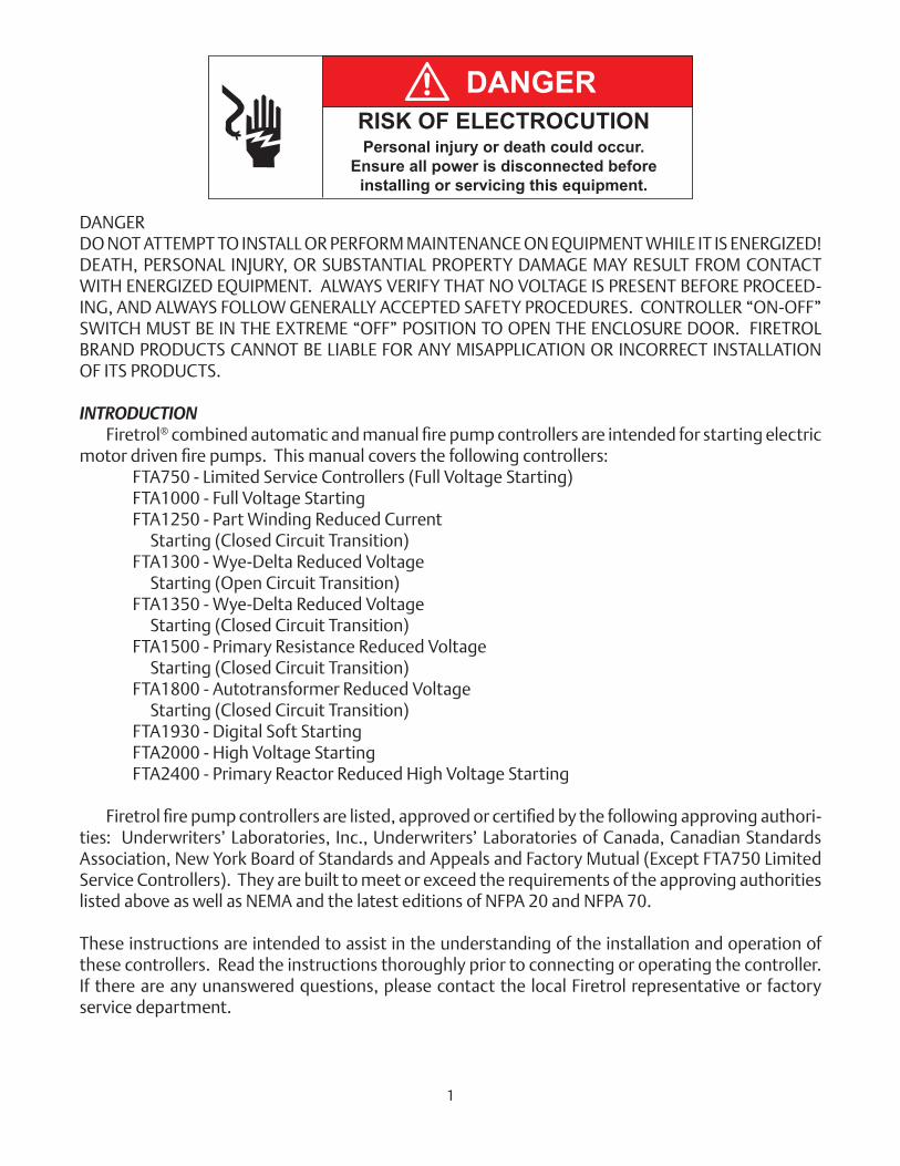
DANGERDO NOT ATTEMPT TO INSTALL OR PERFORM MAINTENANCE ON EQUIPMENT WHILE IT IS ENERGIZED! DEATH, PERSONAL INJURY, OR SUBSTANTIAL PROPERTY DAMAGE MAY RESULT FROM CONTACT WITH ENERGIZED EQUIPMENT. ALWAYS VERIFY THAT NO VOLTAGE IS PRESENT BEFORE PROCEED-ING, AND ALWAYS FOLLOW GENERALLY ACCEPTED SAFETY PROCEDURES. CONTROLLER “ON-OFF” SWITCH MUST BE IN THE EXTREME “OFF” POSITION TO OPEN THE ENCLOSURE DOOR. FIRETROL BRAND PRODUCTS CANNOT BE LIABLE FOR ANY MISAPPLICATION OR INCORRECT INSTALLATION OF ITS PRODUCTS.
INTRODUCTION Firetrol®combinedautomaticandmanualfirepumpcontrollersareintendedforstartingelectricmotordrivenfirepumps.Thismanualcoversthefollowingcontrollers: FTA750 - Limited Service Controllers (Full Voltage Starting) FTA1000 - Full Voltage Starting FTA1250 - Part Winding Reduced Current Starting (Closed Circuit Transition) FTA1300 - Wye-Delta Reduced Voltage Starting (Open Circuit Transition) FTA1350 - Wye-Delta Reduced Voltage Starting (Closed Circuit Transition) FTA1500 - Primary Resistance Reduced Voltage Starting (Closed Circuit Transition) FTA1800 - Autotransformer Reduced Voltage Starting (Closed Circuit Transition) FTA1930 - Digital Soft Starting FTA2000 - High Voltage Starting FTA2400 - Primary Reactor Reduced High Voltage Starting
Firetrolfirepumpcontrollersarelisted,approvedorcertifiedbythefollowingapprovingauthori-ties: Underwriters’ Laboratories, Inc., Underwriters’ Laboratories of Canada, Canadian Standards Association, New York Board of Standards and Appeals and Factory Mutual (Except FTA750 Limited Service Controllers). They are built to meet or exceed the requirements of the approving authorities listed above as well as NEMA and the latest editions of NFPA 20 and NFPA 70. These instructions are intended to assist in the understanding of the installation and operation of these controllers. Read the instructions thoroughly prior to connecting or operating the controller. If there are any unanswered questions, please contact the local Firetrol representative or factory service department.
DANGERRISK OF ELECTROCUTIONPersonal injury or death could occur.
Ensure all power is disconnected before installing or servicing this equipment.
1
MOUNTING CONTROLLERNOTE—Consult the appropriate job plans to determine the controller mounting location. Tools and materials (all mounting) required: 1. Assortment of common hand tools of the type used to service electromechanical equipment.2.Drillfordrillingwall/flooranchorholes. 3. Hole (conduit) punch. 4. Hand level. 5. Tape measure. 6. Four anchors with bolts and washers, per enclosure - if wall mount.7.Mountinghardwareforfloor/wallmount.
Wall Mount— (Optional - If Ordered)Procedure—1. Locate bottom mounting brackets and hardware.2. Inspect for damage.3. Gently lay the controller on its back, using protection so the paint is not damaged. It is best to lay
the controller in a location that is out of the way from actual mounting location.4. Removeexistingfloormountinglegsifsupplied.Attacheachbrackettothebottomoftheen-
closure using the supplied hardware . Tighten nuts securely.
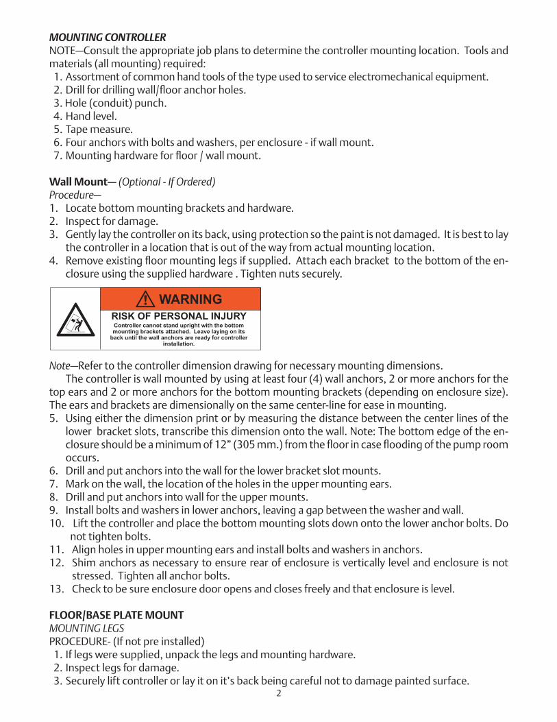
Note—Refer to the controller dimension drawing for necessary mounting dimensions.The controller is wall mounted by using at least four (4) wall anchors, 2 or more anchors for the
top ears and 2 or more anchors for the bottom mounting brackets (depending on enclosure size). The ears and brackets are dimensionally on the same center-line for ease in mounting.5. Using either the dimension print or by measuring the distance between the center lines of the
lower bracket slots, transcribe this dimension onto the wall. Note: The bottom edge of the en-closureshouldbeaminimumof12”(305mm.)fromthefloorincase floodingofthepumproomoccurs.
6. Drill and put anchors into the wall for the lower bracket slot mounts.7. Mark on the wall, the location of the holes in the upper mounting ears.8. Drill and put anchors into wall for the upper mounts.9. Install bolts and washers in lower anchors, leaving a gap between the washer and wall.10. Lift the controller and place the bottom mounting slots down onto the lower anchor bolts. Do
not tighten bolts.11. Align holes in upper mounting ears and install bolts and washers in anchors.12. Shim anchors as necessary to ensure rear of enclosure is vertically level and enclosure is not
stressed. Tighten all anchor bolts.13. Check to be sure enclosure door opens and closes freely and that enclosure is level.
FLOOR/BASE PLATE MOUNTMOUNTING LEGSPROCEDURE- (If not pre installed) 1. If legs were supplied, unpack the legs and mounting hardware. 2. Inspect legs for damage. 3. Securely lift controller or lay it on it’s back being careful not to damage painted surface.
WARNINGRISK OF PERSONAL INJURYController cannot stand upright with the bottom mounting brackets attached. Leave laying on its
back until the wall anchors are ready for controller installation.
2
4. Attach each leg to the bottom of the enclosure using the nuts, bolts, and washers provided for each leg. Tighten bolts securely.5.Afterlegsaresecurelyattached,standthecontrolleruponitslegsforfloormounting. Eachleghasthreeholesonthebottomforanchoringtothefloororbaseplate.
NOTE—Consult the appropriate job plans to determine the controller mounting location. Refer to the controller dimension print for necessary mounting dimensions. Thecontrollerisfloor/baseplatemountedbyusingthethreepre-drilledholesineachleg.Theholes are dimensionally on the same line for ease of mounting. 1. Using either the dimension print or by measuring the distance between the center lines of
theholesononeleg,transcribethesedimensionsontofloor/baseplate.2.Drillthreeholesinthefloor/baseplateforanchoringtheleg. 3. Mark the location of the holes for the opposite leg and drill three more holes.4.Securethecontrollertothefloor/baseplatewithboltsandwashersandtighten. 5. Check to be sure the enclosure door opens freely and that the enclosure is level.
MAKING ELECTRICAL CONNECTIONSImportant Precautions—Priortomakinganyfieldconnections:1. Open door of enclosure and inspect internal components and wiring for any signs of frayed or
loose wires or other visible damage.2. Verify that the controller information is what is required on the project: • Firetrol catalog number • Motor voltage and horsepower • Incoming line voltage and frequency • Maximum system pressure3. Projectelectricalcontractormustsupplyallnecessarywiringforfieldconnectionsinaccordance
with the National Electrical Code, local electrical code and any other authority having jurisdic-tion.
4. Refertotheappropriatefieldconnectiondrawingforwiringinformation.
Procedure—Allfieldconnections,remotealarmfunctionsandACwiringarebroughtintotheenclosurethroughthe top, bottom, or side conduit entrances as indicated on the dimension drawing. 1. Use a hole (conduit) punch, not a torch nor a drill, and punch a hole in the enclosure for the size conduit being used. 2. Install necessary conduit.3. Pullallwiresnecessaryforfieldconnections,remotealarmfunctions,ACpowerandallother
optional features. Allow enough excess wire inside the enclosure to make up connections to the appropriate line, load and control terminal block points. Be sure to consult the appropriate fieldconnectiondiagramincludedwiththemanual.Forproperwiresizing,refertotheNational Electrical Code, NFPA 70.
4. Makeallfieldconnectionstotheremotealarmfunctionsandanyotheroptionalfeatures.Con-nect motor to controller load terminals. Do not connect AC power.
WARNINGRISK OF PERSONAL INJURY
Controller is NOT free standing. Do not open doors or attempt to operate equipment while not anchored
to wall or floor.
3
5. Verify AC line voltage, phase and frequency with the controller data plate on the enclosure door prior to connecting.
6. Checktoseethatallconnectionsarebothcorrectlywired(inaccordancewiththefieldconnec-tion diagram) and tight.
7. Close the enclosure door.
MAKING SYSTEM PRESSURE CONNECTIONSThe controller requires one (1) “System Pressure” connection from the system piping to the en-
closure.Theconnectionfitting,1/2”FNPT,isprovidedonthebottom,externalsideoftheenclosurefor this purpose.
GENERAL PRE-START UP OPERATION 1. Controllers are shipped with the EMERGENCY RUN handle in the latched position. Before placing
the controller in service, turn the EMERGENCY RUN handle and release to unlatch. 2. Check the controller for bolts, nuts and electrical connections which may have loosened
during shipment.3. Ifaremotestartpush-buttonisused,connectthewirestoterminalsasshownonfieldconnection
diagram.4. Ifadelugevalveisused,removethefactoryinstalledjumperfromterminalsasshownonfield
connection diagram. Connect wires from the normally closed contact on the deluge valve to terminals.
5. If a FTA200 remote alarm panel is used, connect like numbered terminals in the remote alarm paneltoterminalsinthefirepumpcontroller.TerminalsHandNmustbeconnectedifaFTA200alarm panel is used.
6. If a FTA200 remote alarm panel is used, connect a reliable, separate, supervisory 120 volt power supply to terminals L1 and L2 in the alarm panel.
GENERAL START UP OPERATION General operating procedures are indicated on the data plate fastened to the front of the control-ler enclosure door.Voltage Check— 1. Energize the incoming power feeder. 2. Observe the Mark IIXGscreen.Confirmthatthedisplayedvoltageandfrequencymatchesthe
voltage stamped on the data plate.
4
At this time, it is necessary to prepare the controller for normal operation. See setup instructions for the Mark IIXG. After the Mark IIXG has been configured, return to this section.
MOTOR ROTATION Confirmdirectionofmotorrotationasfollows:FTA750, 1000, 1500, 1800, 2000, 2400 CONTROLLERS 1. On FTA2000, 2400 controller, place “Normal-Off-Test” switch in the Normal position. 2. Close enclosure door. 3. Momentarily close the isolating switch/circuit breaker handle, i.e. move up to the ON position
and then back to OFF. 4. The pump motor should rotate immediately if system pressure is low. If system pressure is not low,
press the manual START push-button and immediately press the manual STOP push-button. 5. Observe direction of motor rotation.6. Ifrotationisincorrect,confirmthattheisolatingswitch/circuitbreakerisintheOFFposition,open
enclosure door and reverse any two of the motor leads (T1, T2, T3) on the load side of contactor 1M. For example, T1 and T2, T1 and T3 or T2 and T3.
7. Retest for proper rotation following steps 1 through 4.
FTA1250 CONTROLLERS 1. Close enclosure door. 2. Momentarily close the isolating switch/circuit breaker handle, i.e. move up to the ON position
and then back to OFF. 3. The pump motor should rotate immediately if system pressure is low. If system pressure is not low,
press the manual START push-button and immediately press the manual STOP push-button. 4. Observe direction of motor rotation.5.Ifrotationisincorrect,confirmthattheisolatingswitch/circuitbreakerisintheOFFposition,open
enclosure door and reverse any two of the corresponding motor leads (T1, T2, T3, T7, T8, T9) on the load side of both contactors 1M and 2M. For example reverse T1 and T2 on contactor 1M and T7 and T8 on contactor 2M; or T1 and T3 on contactor 1M and T7 and T9 on contactor 2M; or T2 and T3 on contactor 1M and T8 and T9 on contactor 2M.
6. Retest for proper rotation following steps 1 through 4.
FTA1300, 1350 CONTROLLERS 1. Close enclosure door. 2. Momentarily close the isolating switch/circuit breaker handle, i.e. move up to the ON position
and then back to OFF. 3. The pump motor should rotate immediately if system pressure is low. If system pressure is not low,
press the manual START push-button and immediately press the manual STOP push-button.
5
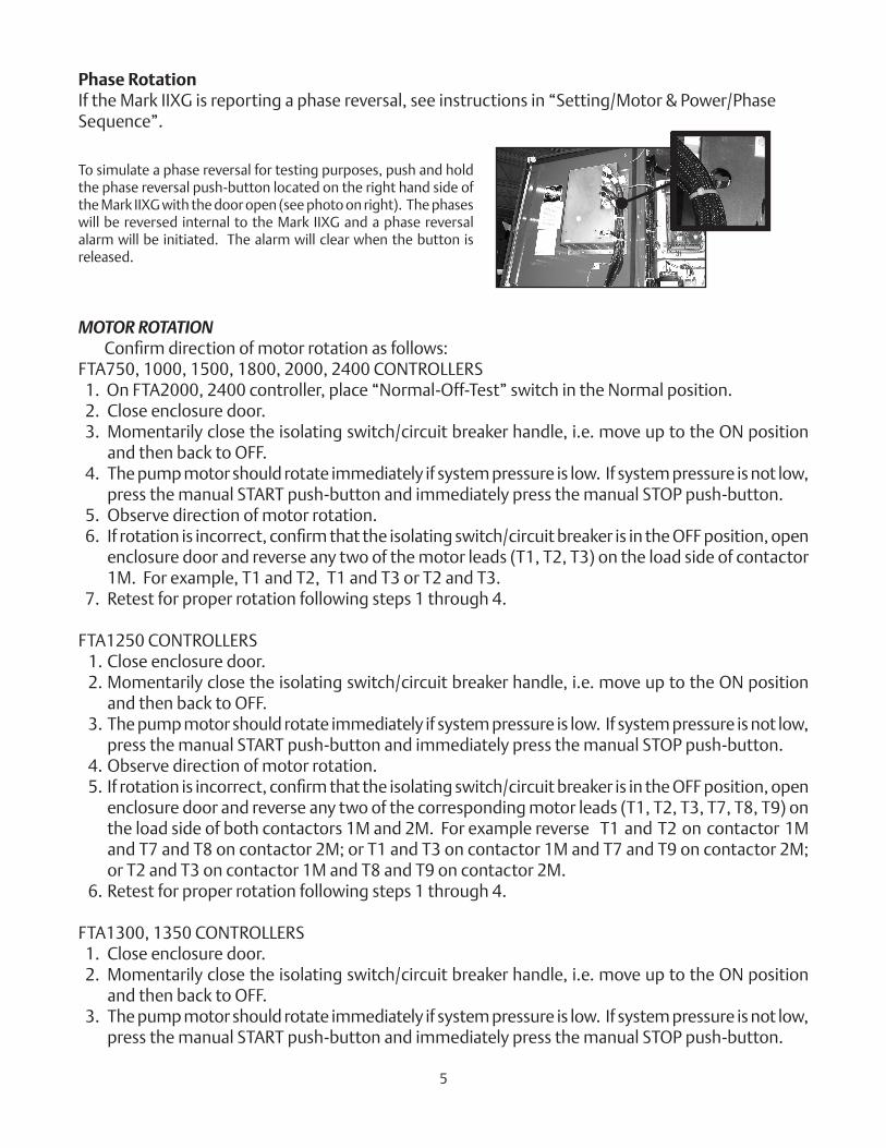
Phase RotationIf the Mark IIXG is reporting a phase reversal, see instructions in “Setting/Motor & Power/Phase Sequence”.
To simulate a phase reversal for testing purposes, push and hold the phase reversal push-button located on the right hand side of the Mark IIXG with the door open (see photo on right). The phases will be reversed internal to the Mark IIXG and a phase reversal alarm will be initiated. The alarm will clear when the button is released.
4. Observe direction of motor rotation.5. Ifrotationis incorrect,confirmthatthe isolatingswitch/circuitbreaker is intheOFFposition,
open enclosure door and reverse any two of the corresponding motor leads (T1, T2, T3, T6/T12, T4/T10, T5/T11) on the load side of both contactors 1M and 2M. For example, reverse T1 and T2 on contactor 1M and T6/T12 and T4/T10 on contactor 2M; or T1 and T3 on contactor 1M and T6/T12 and T5/T11 on contactor 2M; or T2 and T3 on contactor 1M and T4/T10 and T5/T11 on contactor 2M.
6. Retest for proper rotation following steps 1 through 4.
FTA1930 Controllers 1. Close enclosure door. 2. Momentarily close the isolating switch/circuit breaker handle, i.e. move up to the ON position
and then back to OFF. 3. The pump motor should rotate immediately if system pressure is low. If system pressure is not low,
press the manual START push-button and immediately press the manual STOP push-button. 4. Observe direction of motor rotation.5. Ifrotationisincorrect,confirmthattheisolatingswitch/circuitbreakerisintheOFFposition,open
enclosure door and reverse any two of the motor leads (T1, T2, T3) on the load side of contactor 1M. For example, T1 and T2, T1 and T3 or T2 and T3.
6. Retest for proper rotation following steps 1 through 4
FTA900, 975 POWER TRANSFER SWITCH1. Confirmmotorrotationfromthenormalpowersourceforthecontrollerasoutlinedabove. 2. Open both the controller isolating disconnect switch/circuit breaker and the transfer switch iso-
lating disconnect switch by moving the operating handles to the OFF position. 3. Refer to the Automatic Transfer Switch Operator’s Manual. Manually transfer the switch to the
emergency power source. 4. Start the generator set at the generator control panel. 5. With the generator running at stable voltage and frequency momentarily close the power transfer
switch isolating disconnect switch. The pump motor should rotate immediately if system pres-sure is low. If system pressure is not low, press the manual START push-button and immediately press the manual STOP push-button.
6. Observemotor rotation. Confirmthatthe isolatingswitch is in theOFFposition. Shutdowngenerator set.
7. If rotation is incorrect, reverse any two of the line leads at the power transfer switch isolating disconnect switch (L1, L2, L3). For example, L1 and L2, or L2 and L3, or L1 and L3.
8. Retest for proper rotation following steps 1 through 6.
FTA950, 976 POWER TRANSFER SWITCH1. Confirmmotorrotationfromthenormalpowersourceforthecontrollerasoutlinedabove. 2. Open both the controller and transfer switch isolating disconnect/circuit breakers by moving the
operating handles to the OFF position. 3. Refer to the Automatic Transfer Switch Operator’s Manual. Manually transfer the switch to the
emergency power source. 4. Momentarily close the power transfer switch isolating disconnect switch/circuit breaker.
The pump motor should rotate immediately if system pressure is low. If system pressure is not low, press the manual START push-button and immediately press the manual STOP push-button.
5. Observe motor rotation.6. Ifrotationisincorrect,confirmthattheisolatingdisconnectswitch/circuitbreakersarein
the OFF position. Request the utility company to disconnect the second utility incoming power at the source, then reverse any two of the line leads at the power transfer switch isolating disconnect switch (L1, L2, L3). For example, L1 and L2, L1 and L3, or L2 and L3.
7. Retest for proper rotation following steps 1 through 5 above.6
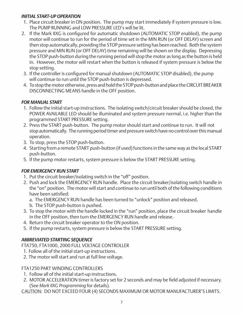
INITIAL START-UP OPERATION 1. Place circuit breaker in ON position. The pump may start immediately if system pressure is low.
The PUMP RUNNING and LOW PRESSURE LED’s will be lit.2. IftheMarkIIXGisconfiguredforautomaticshutdown(AUTOMATICSTOPenabled),thepump
motor will continue to run for the period of time set in the MIN RUN (or OFF DELAY) screen and then stop automatically, providing the STOP pressure setting has been reached. Both the system pressure and MIN RUN (or OFF DELAY) time remaining will be shown on the display. Depressing the STOP push-button during the running period will stop the motor as long as the button is held in. However, the motor will restart when the button is released if system pressure is below the stop setting.
3. Ifthecontrollerisconfiguredformanualshutdown(AUTOMATICSTOPdisabled),thepump will continue to run until the STOP push-button is depressed. 4. To stop the motor otherwise, press and hold the STOP push-button and place the CIRCUIT BREAKER
DISCONNECTING MEANS handle in the OFF position.
FOR MANUAL START 1. Follow the initial start-up instructions. The isolating switch/circuit breaker should be closed, the
POWER AVAILABLE LED should be illuminated and system pressure normal, i.e. higher than the programmed START PRESSURE setting.
2. Press the START push-button. The pump motor should start and continue to run. It will not stop automatically. The running period timer and pressure switch have no control over this manual
operation. 3. To stop, press the STOP push-button. 4. Starting from a remote START push-button (if used) functions in the same way as the local START
push-button. 5. If the pump motor restarts, system pressure is below the START PRESSURE setting.
FOR EMERGENCY RUN START 1. Put the circuit breaker/isolating switch in the “off” position. 2. Push and lock the EMERGENCY RUN handle. Place the circuit breaker/isolating switch handle in
the “on” position. The motor will start and continue to run until both of the following conditions havebeensatisfied:
a. The EMERGENCY RUN handle has been turned to “unlock” position and released. b. The STOP push-button is pushed. 3. To stop the motor with the handle locked in the “run” position, place the circuit breaker handle
in the OFF position, then turn the EMERGENCY RUN handle and release. 4. Return the circuit breaker operator to the ON position. 5. If the pump restarts, system pressure is below the START PRESSURE setting.
ABBREVIATED STARTING SEQUENCEFTA750, FTA1000, 2000 FULL VOLTAGE CONTROLLER 1. Follow all of the initial start-up instructions. 2. The motor will start and run at full line voltage.
FTA1250 PART WINDING CONTROLLERS 1. Follow all of the initial start-up instructions.2. MOTORACCELERATIONtimerisfactorysetfor2secondsandmaybefieldadjustedifnecessary.
(See Mark IIXG Programming for details).CAUTION: DO NOT EXCEED FOUR (4) SECONDS MAXIMUM OR MOTOR MANUFACTURER’S LIMITS.
7
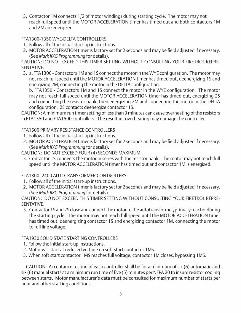
3. Contactor 1M connects 1/2 of motor windings during starting cycle. The motor may not reach full speed until the MOTOR ACCELERATION timer has timed out and both contactors 1M and 2M are energized.
FTA1300-1350 WYE-DELTA CONTROLLERS 1 1. Follow all of the initial start-up instructions.2. MOTORACCELERATIONtimerisfactorysetfor2secondsandmaybefieldadjustedifnecessary.
(See Mark IIXG Programming for details).CAUTION: DO NOT EXCEED THIS TIMER SETTING WITHOUT CONSULTING YOUR FIRETROL REPRE-SENTATIVE.3. a.FTA1300-Contactors1Mand1SconnectthemotorintheWYEconfiguration.Themotormay
not reach full speed until the MOTOR ACCELERATION timer has timed out, deenergizing 1S and energizing2M,connectingthemotorintheDELTAconfiguration.
b.FTA1350-Contactors1Mand1SconnectthemotorintheWYEconfiguration.Themotormay not reach full speed until the MOTOR ACCELERATION timer has timed out, energizing 2S and connecting the resistor bank, then energizing 2M and connecting the motor in the DELTA configuration.2Scontactsdeenergizecontactor1S.
CAUTION: A minimum run timer setting of less than 3 minutes can cause overheating of the resistors in FTA1350 and FTA1500 controllers. The resultant overheating may damage the controller.
FTA1500 PRIMARY RESISTANCE CONTROLLERS 1 1. Follow all of the initial start-up instructions.2. MOTORACCELERATIONtimerisfactorysetfor2secondsandmaybefieldadjustedifnecessary.
(See Mark IIXG Programming for details).CAUTION: DO NOT EXCEED FOUR (4) SECONDS MAXIMUM. 3. Contactor 1S connects the motor in series with the resistor bank. The motor may not reach full
speed until the MOTOR ACCELERATION timer has timed out and contactor 1M is energized.
FTA1800, 2400 AUTOTRANSFORMER CONTROLLERS 1. Follow all of the initial start-up instructions.2. MOTORACCELERATIONtimerisfactorysetfor2secondsandmaybefieldadjustedifnecessary.
(See Mark IIXG Programming for details).CAUTION: DO NOT EXCEED THIS TIMER SETTING WITHOUT CONSULTING YOUR FIRETROL REPRE-SENTATIVE. 3. Contactor 1S and 2S close and connect the motor to the autotransformer/primary reactor during
the starting cycle. The motor may not reach full speed until the MOTOR ACCELERATION timer has timed out, deenergizing contactor 1S and energizing contactor 1M, connecting the motor to full line voltage.
FTA1930 SOLID STATE STARTING CONTROLLERS 1. Follow the initial start-up instructions. 2. Motor will start at reduced voltage on soft start contactor 1MS. 3. When soft start contactor 1MS reaches full voltage, contactor 1M closes, bypassing 1MS.
1 CAUTION: Acceptance testing of each controller shall be for a minimum of six (6) automatic and six(6)manualstartsataminimumruntimeoffive(5)minutesperNFPA20toinsureresistorcoolingbetween starts. Motor manufacturer’s data must be consulted for maximum number of starts per hour and other starting conditions.
8
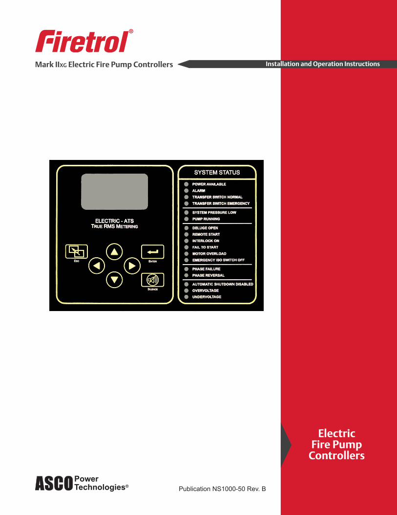
POWER AVAILABLEALARMTRANSFER SWITCH NORMALTRANSFER SWITCH EMERGENCY
SYSTEM PRESSURE LOWPUMP RUNNING
DELUGE OPENREMOTE STARTINTERLOCK ONFAIL TO STARTMOTOR OVERLOADEMERGENCY ISO SWITCH OFF
PHASE FAILUREPHASE REVERSAL
AUTOMATIC SHUTDOWN DISABLEDOVERVOLTAGEUNDERVOLTAGE
SYSTEM STATUS
ELECTRIC - ATSTRUE RMS METERING
Esc Enter
Silence
Esc Enter
Silence
Running 152 psi60.3H
Z a b cABC
Volts 462 464 459Amps 115117 114Pump RunningMin Run 7:26
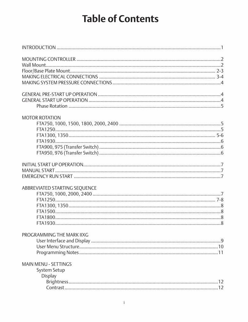
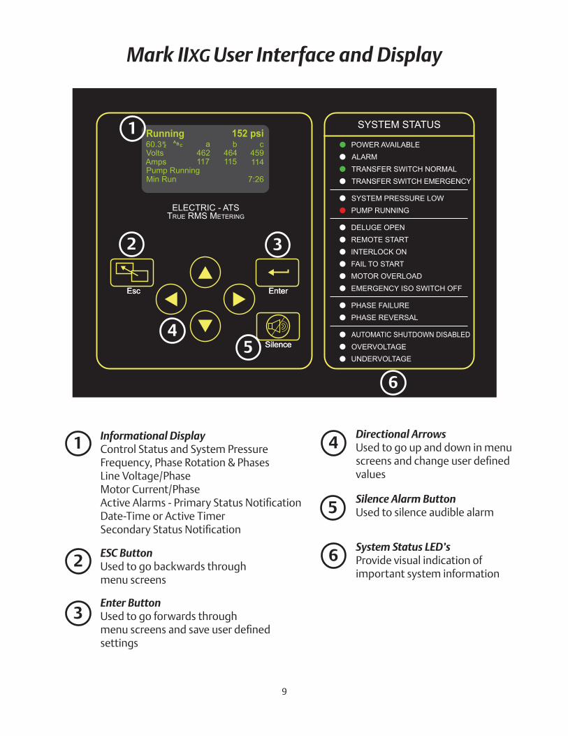
Mark IIXG User Interface and Display
1
2
4
3
5
6
Informational DisplayControl Status and System PressureFrequency, Phase Rotation & PhasesLine Voltage/PhaseMotor Current/PhaseActiveAlarms-PrimaryStatusNotificationDate-Time or Active TimerSecondaryStatusNotification
1
ESC ButtonUsed to go backwards throughmenu screens
2
Enter ButtonUsed to go forwards throughmenuscreensandsaveuserdefinedsettings
3
Directional ArrowsUsed to go up and down in menu screensandchangeuserdefinedvalues
Silence Alarm ButtonUsed to silence audible alarm
System Status LED’sProvide visual indication of important system information
4
5
6
9
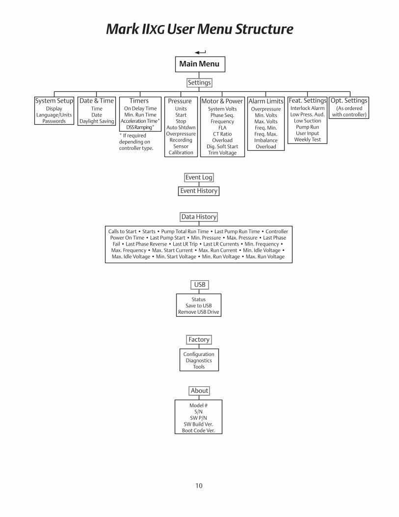
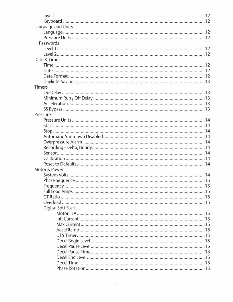
Mark IIXG User Menu Structure
Main Menu
Settings
System Setup Date & Time Timers Pressure Motor & Power Alarm Limits Feat. SettingsDisplay
Language/UnitsPasswords
TimeDate
Daylight Saving
On Delay TimeMin. Run Time
Acceleration Time*DSS Ramping*
UnitsStartStop
Auto ShtdwnOverpressure
RecordingSensor
Calibration
System VoltsPhase Seq.Frequency
FLACT RatioOverload
Dig. Soft StartTrim Voltage
OverpressureMin. VoltsMax. VoltsFreq. Min.Freq. Max.ImbalanceOverload
Interlock AlarmLow Press. Aud.
Low SuctionPump RunUser Input
Weekly Test
Event Log
Event History
Data History
Calls to Start • Starts • Pump Total Run Time • Last Pump Run Time • Controller Power On Time • Last Pump Start • Min. Pressure • Max. Pressure • Last Phase
Fail • Last Phase Reverse • Last LR Trip • Last LR Currents • Min. Frequency • Max. Frequency • Max. Start Current • Max. Run Current • Min. Idle Voltage • Max. Idle Voltage • Min. Start Voltage • Min. Run Voltage • Max. Run Voltage
Opt. Settings
USB
StatusSave to USB
Remove USB Drive
Factory
ConfigurationDiagnostics
Tools
About
Model #S/N
SW P/NSW Build Ver.
Boot Code Ver.
(As orderedwith controller)
* If required depending on controller type.
10
Programming Notes
The Firetrol Mark IIxg is multi-level password protected. User programmable functions are protected by a Level 1 password.
LEVEL 1 PASSWORD2 - 1 - 1 - 2
Note: Many menu settings feature an “enable/disable” option. These options are indicated by a
“ü” for enabled or a “x” for disabled. In many cases this can also be interpreted as “ü” for yes
or a “x” for no.
1 Indicates the level of password required to modify a setting.
11
WARNINGRISK OF PROPERY LOSS,
DEATH OR INJURYIncorrect or inappropriate controller settings could render the fire protection system inoperable. Only qualified and knowl-
edgeable personnel should operate this equipment.
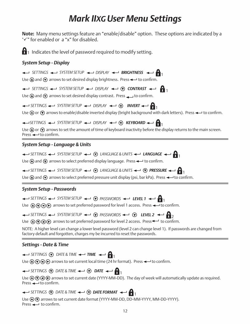
Mark IIXG User Menu Settings
SETTINGS SYSTEM SETUP DISPLAY BRIGHTNESS 1Useandarrowstosetdesireddisplaybrightness.Presstoconfirm.
System Setup - Display
SETTINGS SYSTEM SETUP DISPLAY CONTRAST 1Useandarrowstosetdesireddisplaycontrast.Presstoconfirm.
SETTINGS SYSTEM SETUP DISPLAY INVERT 1Useorarrowstoenable/disableinverteddisplay(brightbackgroundwithdarkletters).Presstoconfirm.
SETTINGS SYSTEM SETUP DISPLAY KEYBOARD 1Use or arrows to set the amount of time of keyboard inactivity before the display returns to the main screen. Presstoconfirm.
System Setup - Language & Units
SETTINGS SYSTEM SETUP LANGUAGE & UNITS LANGUAGE 1Useandarrowstoselectpreferreddisplaylanguage.Presstoconfirm.
SETTINGS SYSTEM SETUP LANGUAGE & UNITS PRESSURE 1Useandarrowstoselectpreferredpressureunitdisplay(psi,barkPa).Presstoconfirm.
Note: Many menu settings feature an “enable/disable” option. These options are indicated by a "ü” for enabled or a “x” for disabled.
1 Indicates the level of password required to modify setting.
System Setup - Passwords
SETTINGS SYSTEM SETUP PASSWORDS LEVEL 1 1Usearrowstosetpreferredpasswordforlevel1access.Presstoconfirm.
SETTINGS SYSTEM SETUP PASSWORDS LEVEL 2 2Usearrowstosetpreferredpasswordforlevel2access.Presstoconfirm.
NOTE: A higher level can change a lower level password (level 2 can change level 1). If passwords are changed from factory default and forgotten, charges my be incurred to reset the passwords.
Settings - Date & Time
SETTINGS DATE & TIME TIME 1Usearrowstosetcurrentlocaltime(24hrformat).Presstoconfirm.
SETTINGS DATE & TIME DATE 1Use arrows to set current date (YYYY-MM-DD). The day of week will automatically update as required. Presstoconfirm.
SETTINGS DATE & TIME DATE FORMAT 1Use arrows to set current date format (YYYY-MM-DD, DD-MM-YYYY, MM-DD-YYYY).Presstoconfirm.
12
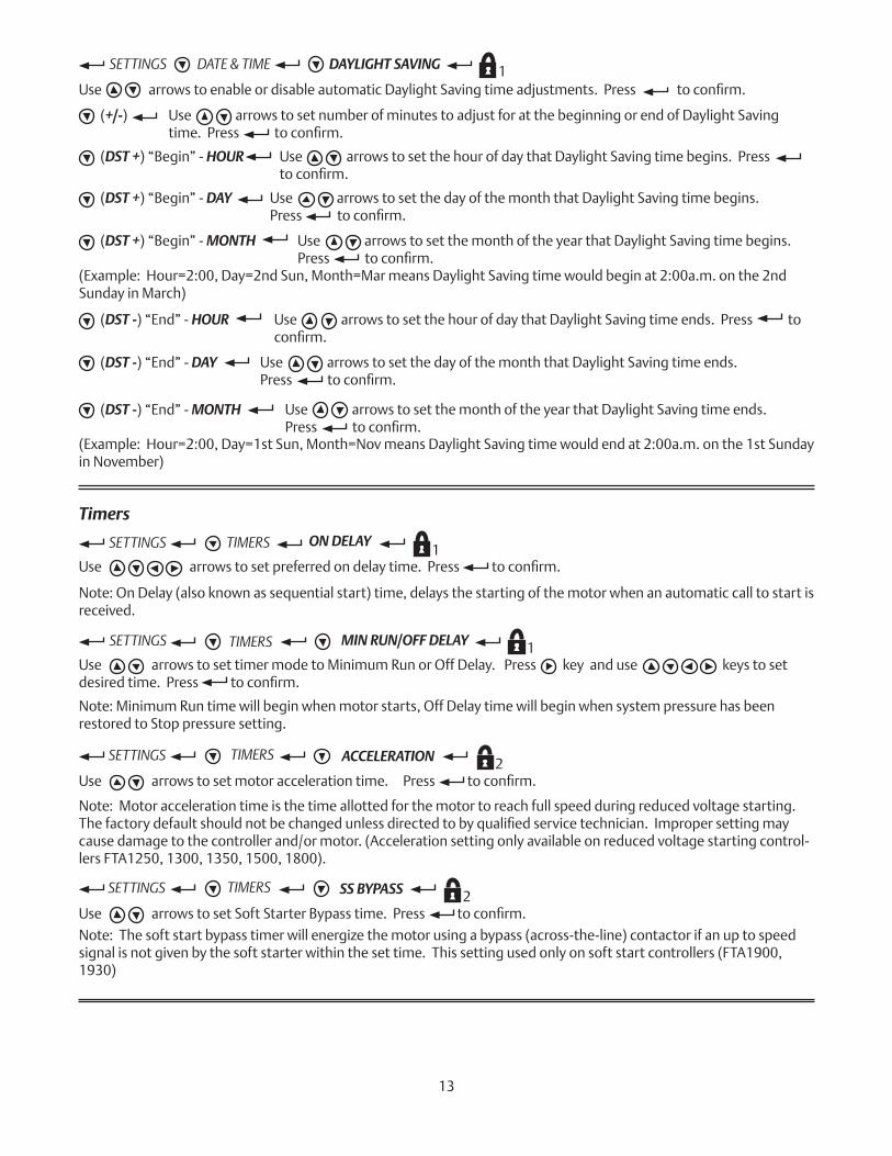
SETTINGS DATE & TIME DAYLIGHT SAVING 1UsearrowstoenableordisableautomaticDaylightSavingtimeadjustments.Presstoconfirm.
(DST +) “Begin” - HOUR
Use arrows to set number of minutes to adjust for at the beginning or end of Daylight Saving time.Presstoconfirm.
(+/-)
Use arrows to set the hour of day that Daylight Saving time begins. Press toconfirm.
(DST +) “Begin” - DAY Use arrows to set the day of the month that Daylight Saving time begins. Presstoconfirm.
(DST +) “Begin” - MONTH Use arrows to set the month of the year that Daylight Saving time begins. Presstoconfirm.
(Example: Hour=2:00, Day=2nd Sun, Month=Mar means Daylight Saving time would begin at 2:00a.m. on the 2nd Sunday in March)
(DST -) “End” - HOUR Use arrows to set the hour of day that Daylight Saving time ends. Press to confirm.
(DST -) “End” - DAY Use arrows to set the day of the month that Daylight Saving time ends. Presstoconfirm.
(DST -) “End” - MONTH Use arrows to set the month of the year that Daylight Saving time ends. Presstoconfirm.
(Example: Hour=2:00, Day=1st Sun, Month=Nov means Daylight Saving time would end at 2:00a.m. on the 1st Sunday in November)
Timers
SETTINGS TIMERS ON DELAY1
Usearrowstosetpreferredondelaytime.Presstoconfirm.
Note: On Delay (also known as sequential start) time, delays the starting of the motor when an automatic call to start is received.
SETTINGS TIMERS MIN RUN/OFF DELAY 1Use arrows to set timer mode to Minimum Run or Off Delay. Press key and use keys to set desiredtime.Presstoconfirm.
Note: Minimum Run time will begin when motor starts, Off Delay time will begin when system pressure has been restored to Stop pressure setting.
SETTINGS TIMERS ACCELERATION 2Usearrowstosetmotoraccelerationtime.Presstoconfirm.
Note: Motor acceleration time is the time allotted for the motor to reach full speed during reduced voltage starting. Thefactorydefaultshouldnotbechangedunlessdirectedtobyqualifiedservicetechnician.Impropersettingmaycause damage to the controller and/or motor. (Acceleration setting only available on reduced voltage starting control-lers FTA1250, 1300, 1350, 1500, 1800).
SETTINGS TIMERS SS BYPASS 2UsearrowstosetSoftStarterBypasstime.Presstoconfirm.
Note: The soft start bypass timer will energize the motor using a bypass (across-the-line) contactor if an up to speed signal is not given by the soft starter within the set time. This setting used only on soft start controllers (FTA1900, 1930)
13
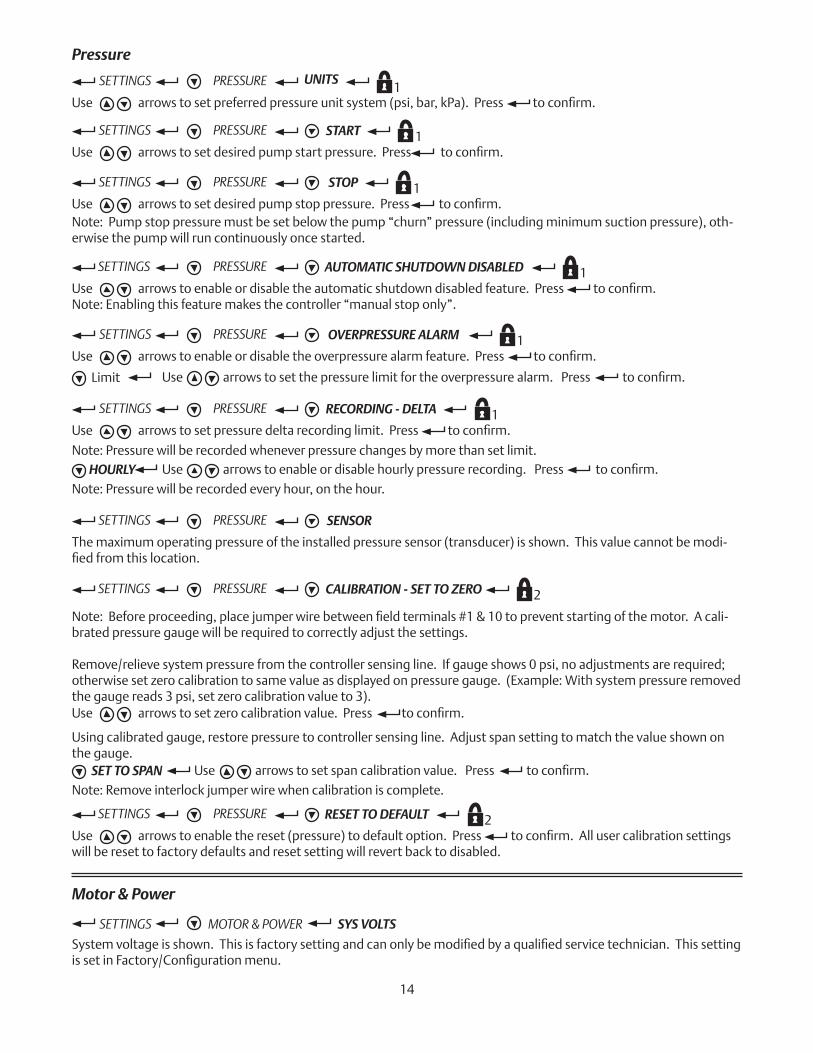
Pressure
SETTINGS PRESSURE UNITS1
Usearrowstosetpreferredpressureunitsystem(psi,bar,kPa).Presstoconfirm.
SETTINGS PRESSURE START 1Usearrowstosetdesiredpumpstartpressure.Presstoconfirm.
SETTINGS PRESSURE STOP 1Usearrowstosetdesiredpumpstoppressure.Presstoconfirm.Note: Pump stop pressure must be set below the pump “churn” pressure (including minimum suction pressure), oth-erwise the pump will run continuously once started.
SETTINGS PRESSURE AUTOMATIC SHUTDOWN DISABLED 1Usearrowstoenableordisabletheautomaticshutdowndisabledfeature.Presstoconfirm.Note: Enabling this feature makes the controller “manual stop only”.
SETTINGS PRESSURE OVERPRESSURE ALARM 1Usearrowstoenableordisabletheoverpressurealarmfeature.Presstoconfirm.
Limit Usearrowstosetthepressurelimitfortheoverpressurealarm.Presstoconfirm.
SETTINGS PRESSURE RECORDING - DELTA 1Usearrowstosetpressuredeltarecordinglimit.Presstoconfirm.
HOURLY Usearrowstoenableordisablehourlypressurerecording.Presstoconfirm.Note: Pressure will be recorded whenever pressure changes by more than set limit.
Note: Pressure will be recorded every hour, on the hour.
SETTINGS PRESSURE CALIBRATION - SET TO ZERO 2
Usearrowstosetzerocalibrationvalue.Presstoconfirm.
SET TO SPAN Usearrowstosetspancalibrationvalue.Presstoconfirm.
Note: Remove interlock jumper wire when calibration is complete.
Note:Beforeproceeding,placejumperwirebetweenfieldterminals#1&10topreventstartingofthemotor.Acali-brated pressure gauge will be required to correctly adjust the settings.
Remove/relieve system pressure from the controller sensing line. If gauge shows 0 psi, no adjustments are required; otherwise set zero calibration to same value as displayed on pressure gauge. (Example: With system pressure removed the gauge reads 3 psi, set zero calibration value to 3).
Using calibrated gauge, restore pressure to controller sensing line. Adjust span setting to match the value shown on the gauge.
SETTINGS PRESSURE SENSOR
The maximum operating pressure of the installed pressure sensor (transducer) is shown. This value cannot be modi-fiedfromthislocation.
Motor & Power
SETTINGS MOTOR & POWER SYS VOLTS
Systemvoltageisshown.Thisisfactorysettingandcanonlybemodifiedbyaqualifiedservicetechnician.ThissettingissetinFactory/Configurationmenu.
SETTINGS PRESSURE RESET TO DEFAULT 2Usearrowstoenablethereset(pressure)todefaultoption.Presstoconfirm.Allusercalibrationsettingswill be reset to factory defaults and reset setting will revert back to disabled.
14
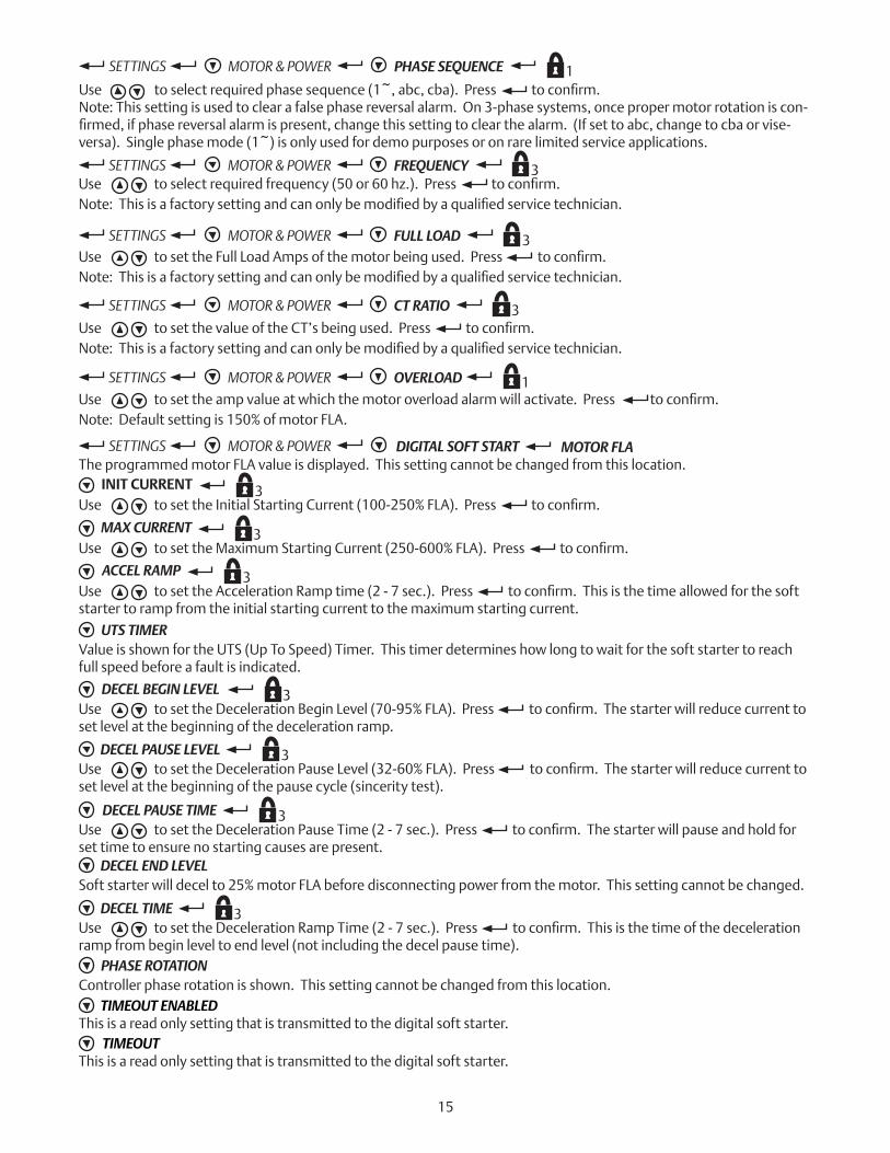
UsetosettheFullLoadAmpsofthemotorbeingused.Presstoconfirm.Note:Thisisafactorysettingandcanonlybemodifiedbyaqualifiedservicetechnician.
UsetosetthevalueoftheCT’sbeingused.Presstoconfirm.Note:Thisisafactorysettingandcanonlybemodifiedbyaqualifiedservicetechnician.
Usetosettheampvalueatwhichthemotoroverloadalarmwillactivate.Presstoconfirm.Note: Default setting is 150% of motor FLA.
Usetoselectrequiredfrequency(50or60hz.).Presstoconfirm.Note:Thisisafactorysettingandcanonlybemodifiedbyaqualifiedservicetechnician.
DIGITAL SOFT STARTThe programmed motor FLA value is displayed. This setting cannot be changed from this location.
MOTOR FLA
INIT CURRENT 3UsetosettheInitialStartingCurrent(100-250%FLA).Presstoconfirm.
MAX CURRENT 3UsetosettheMaximumStartingCurrent(250-600%FLA).Presstoconfirm.
ACCEL RAMP 3UsetosettheAccelerationRamptime(2-7sec.).Presstoconfirm.Thisisthetimeallowedforthesoftstarter to ramp from the initial starting current to the maximum starting current.
UTS TIMERValue is shown for the UTS (Up To Speed) Timer. This timer determines how long to wait for the soft starter to reach full speed before a fault is indicated.
DECEL BEGIN LEVEL 3UsetosettheDecelerationBeginLevel(70-95%FLA).Presstoconfirm.Thestarterwillreducecurrenttoset level at the beginning of the deceleration ramp.
DECEL PAUSE LEVEL 3UsetosettheDecelerationPauseLevel(32-60%FLA).Presstoconfirm.Thestarterwillreducecurrenttoset level at the beginning of the pause cycle (sincerity test).
DECEL PAUSE TIME 3UsetosettheDecelerationPauseTime(2-7sec.).Presstoconfirm.Thestarterwillpauseandholdforset time to ensure no starting causes are present.
DECEL END LEVELSoft starter will decel to 25% motor FLA before disconnecting power from the motor. This setting cannot be changed.
DECEL TIME 3UsetosettheDecelerationRampTime(2-7sec.).Presstoconfirm.Thisisthetimeofthedecelerationramp from begin level to end level (not including the decel pause time).
PHASE ROTATIONController phase rotation is shown. This setting cannot be changed from this location.
3SETTINGS MOTOR & POWER FREQUENCY
3SETTINGS MOTOR & POWER FULL LOAD
3SETTINGS MOTOR & POWER CT RATIO
1SETTINGS MOTOR & POWER OVERLOAD
SETTINGS MOTOR & POWER
TIMEOUT ENABLEDThis is a read only setting that is transmitted to the digital soft starter.
TIMEOUTThis is a read only setting that is transmitted to the digital soft starter.
1Usetoselectrequiredphasesequence(1~,abc,cba).Presstoconfirm.Note: This setting is used to clear a false phase reversal alarm. On 3-phase systems, once proper motor rotation is con-firmed,ifphasereversalalarmispresent,changethissettingtoclearthealarm.(Ifsettoabc,changetocbaorvise-versa). Single phase mode (1~) is only used for demo purposes or on rare limited service applications.
SETTINGS MOTOR & POWER PHASE SEQUENCE
15
Alarm Limits
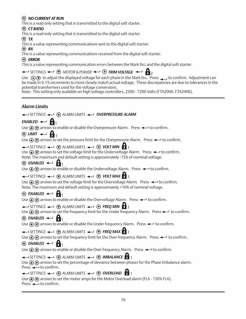
SETTINGS ALARM LIMITS OVERPRESSURE ALARM
Use to adjust the displayed voltage for each phase in the Mark IIXG.Presstoconfirm.Adjustmentcanbe made in 0.1% increments to more closely match actual voltage. These discrepancies are due to tolerances in the potential transformers used for the voltage conversions.
ENABLED 1UsearrowstoenableordisabletheOverpressureAlarm.Presstoconfirm.
LIMIT 1UsearrowstosetthepressurelimitfortheOverpressureAlarm.Presstoconfirm.
1UsearrowstosetthevoltagelimitfortheUndervoltageAlarm.Presstoconfirm.Note: The maximum and default setting is approximately -15% of nominal voltage.
UsearrowstoenableordisabletheUndervoltageAlarm.Presstoconfirm.
UsearrowstosetthevoltagelimitfortheOvervoltageAlarm.Presstoconfirm.Note: The maximum and default setting is approximately +10% of nominal voltage.
UsearrowstoenableordisabletheOvervoltageAlarm.Presstoconfirm.
Note: This setting only available on high voltage controllers, 2300 - 7200 Volts (FTA2000, FTA2400).
UsearrowstosetthefrequencylimitfortheUnderfrequencyAlarm.Presstoconfirm.
UsearrowstoenableordisabletheUnderfrequencyAlarm.Presstoconfirm.
UsearrowstosetthefrequencylimitfortheOverfrequencyAlarm.Presstoconfirm.
UsearrowstoenableordisabletheOverfrequencyAlarm.Presstoconfirm.
Use arrows to set the percentage of deviance between phases for the Phase Imbalance alarm. Presstoconfirm.
Use arrows to set the motor amps for the Motor Overload alarm (FLA - 150% FLA). Presstoconfirm.
TXThis is a value representing communications sent to the digital soft starter.
RXThis is a value representing communications received from the digital soft starter.
ERRORThis is a value representing communication errors between the Mark IIXG and the digital soft starter.
2SETTINGS MOTOR & POWER TRIM VOLTAGE
SETTINGS ALARM LIMITS VOLT MIN
ENABLED 1
1SETTINGS ALARM LIMITS VOLT MAX
ENABLED 1
1SETTINGS ALARM LIMITS FREQ MIN
ENABLED 1
1SETTINGS ALARM LIMITS FREQ MAX
ENABLED 1
1SETTINGS ALARM LIMITS IMBALANCE
1SETTINGS ALARM LIMITS OVERLOAD
NO CURRENT AT RUNThis is a read only setting that is transmitted to the digital soft starter.
CT RATIOThis is a read only setting that is transmitted to the digital soft starter.
16
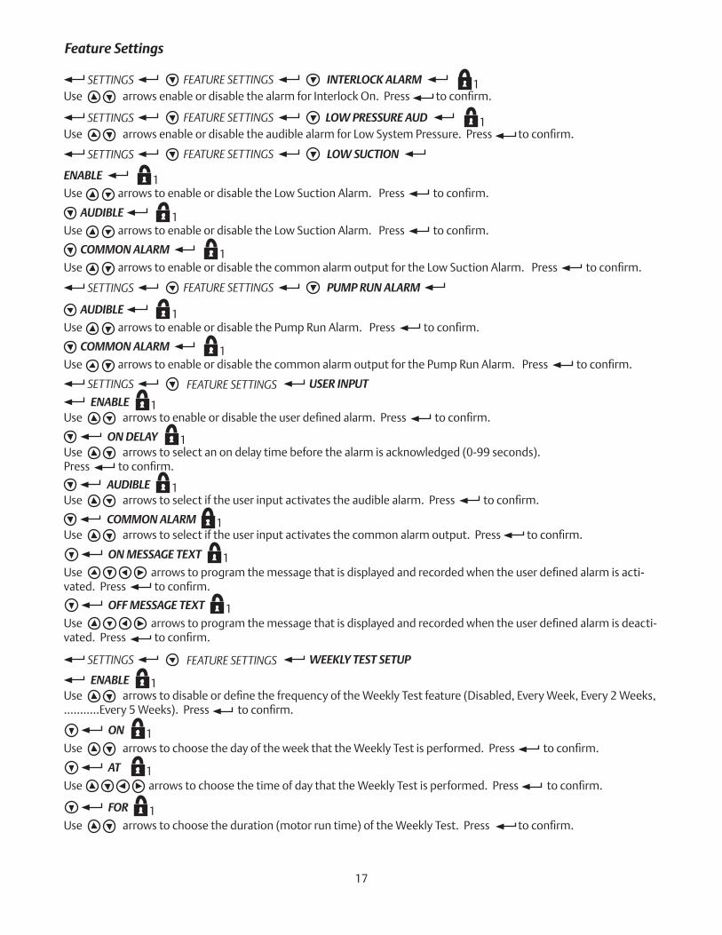
SETTINGS FEATURE SETTINGS 1INTERLOCK ALARMUsearrowsenableordisablethealarmforInterlockOn.Presstoconfirm.
SETTINGS FEATURE SETTINGS 1LOW PRESSURE AUDUsearrowsenableordisabletheaudiblealarmforLowSystemPressure.Presstoconfirm.
SETTINGS FEATURE SETTINGS LOW SUCTION
UsearrowstoenableordisabletheLowSuctionAlarm.Presstoconfirm.
ENABLE 1
AUDIBLE 1UsearrowstoenableordisabletheLowSuctionAlarm.Presstoconfirm.
COMMON ALARM 1UsearrowstoenableordisablethecommonalarmoutputfortheLowSuctionAlarm.Presstoconfirm.
SETTINGS FEATURE SETTINGS PUMP RUN ALARM
AUDIBLE 1UsearrowstoenableordisablethePumpRunAlarm.Presstoconfirm.
COMMON ALARM 1UsearrowstoenableordisablethecommonalarmoutputforthePumpRunAlarm.Presstoconfirm.
SETTINGS FEATURE SETTINGS USER INPUT
1ENABLEUsearrowstoenableordisabletheuserdefinedalarm.Presstoconfirm.
1ON DELAYUse arrows to select an on delay time before the alarm is acknowledged (0-99 seconds). Presstoconfirm.
1AUDIBLEUsearrowstoselectiftheuserinputactivatestheaudiblealarm.Presstoconfirm.
1COMMON ALARMUsearrowstoselectiftheuserinputactivatesthecommonalarmoutput.Presstoconfirm.
1ON MESSAGE TEXT
Usearrowstoprogramthemessagethatisdisplayedandrecordedwhentheuserdefinedalarmisacti-vated.Presstoconfirm.
1OFF MESSAGE TEXT
Usearrowstoprogramthemessagethatisdisplayedandrecordedwhentheuserdefinedalarmisdeacti-vated.Presstoconfirm.
Feature Settings
SETTINGS FEATURE SETTINGS WEEKLY TEST SETUP
1ENABLEUsearrowstodisableordefinethefrequencyoftheWeeklyTestfeature(Disabled,EveryWeek,Every2Weeks,...........Every5Weeks).Presstoconfirm.
1ON
UsearrowstochoosethedayoftheweekthattheWeeklyTestisperformed.Presstoconfirm.
1AT
UsearrowstochoosethetimeofdaythattheWeeklyTestisperformed.Presstoconfirm.
1FOR
Usearrowstochoosetheduration(motorruntime)oftheWeeklyTest.Presstoconfirm.
17
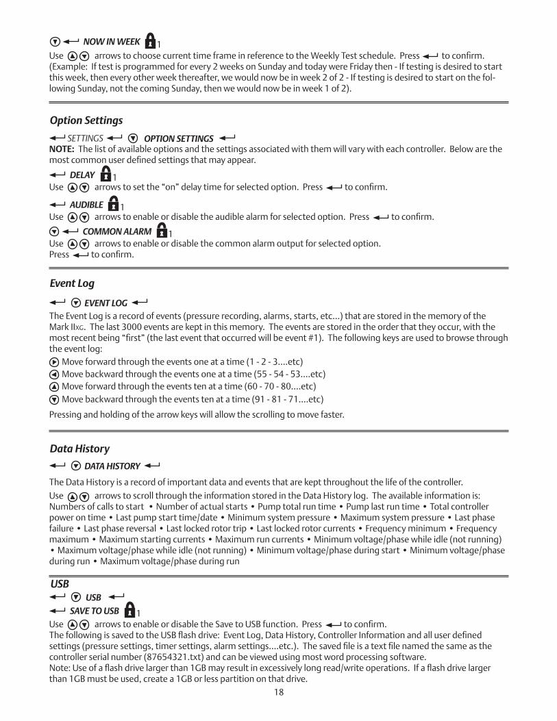
SETTINGS OPTION SETTINGSNOTE: The list of available options and the settings associated with them will vary with each controller. Below are the mostcommonuserdefinedsettingsthatmayappear.
1AUDIBLEUsearrowstoenableordisabletheaudiblealarmforselectedoption.Presstoconfirm.
1COMMON ALARMUse arrows to enable or disable the common alarm output for selected option. Presstoconfirm.
1DELAYUsearrowstosetthe“on”delaytimeforselectedoption.Presstoconfirm.
EVENT LOGThe Event Log is a record of events (pressure recording, alarms, starts, etc...) that are stored in the memory of the Mark IIxg. The last 3000 events are kept in this memory. The events are stored in the order that they occur, with the mostrecentbeing“first”(thelasteventthatoccurredwillbeevent#1).Thefollowingkeysareusedtobrowsethroughthe event log:
Move forward through the events one at a time (1 - 2 - 3....etc)Move backward through the events one at a time (55 - 54 - 53....etc)Move forward through the events ten at a time (60 - 70 - 80....etc)Move backward through the events ten at a time (91 - 81 - 71....etc)
Pressing and holding of the arrow keys will allow the scrolling to move faster.
DATA HISTORY
The Data History is a record of important data and events that are kept throughout the life of the controller.
Use arrows to scroll through the information stored in the Data History log. The available information is:Numbers of calls to start • Number of actual starts • Pump total run time • Pump last run time • Total controller power on time • Last pump start time/date • Minimum system pressure • Maximum system pressure • Last phase failure • Last phase reversal • Last locked rotor trip • Last locked rotor currents • Frequency minimum • Frequency maximum • Maximum starting currents • Maximum run currents • Minimum voltage/phase while idle (not running) • Maximum voltage/phase while idle (not running) • Minimum voltage/phase during start • Minimum voltage/phase during run • Maximum voltage/phase during run
1NOW IN WEEK
UsearrowstochoosecurrenttimeframeinreferencetotheWeeklyTestschedule.Presstoconfirm.(Example: If test is programmed for every 2 weeks on Sunday and today were Friday then - If testing is desired to start this week, then every other week thereafter, we would now be in week 2 of 2 - If testing is desired to start on the fol-lowing Sunday, not the coming Sunday, then we would now be in week 1 of 2).
Option Settings
Event Log
Data History
USBUSB
1SAVE TO USBUsearrowstoenableordisabletheSavetoUSBfunction.Presstoconfirm.ThefollowingissavedtotheUSBflashdrive:EventLog,DataHistory,ControllerInformationandalluserdefinedsettings(pressuresettings,timersettings,alarmsettings....etc.).Thesavedfileisatextfilenamedthesameasthecontroller serial number (87654321.txt) and can be viewed using most word processing software. Note:Useofaflashdrivelargerthan1GBmayresultinexcessivelylongread/writeoperations.Ifaflashdrivelargerthan 1GB must be used, create a 1GB or less partition on that drive.
18
1REMOVE DRIVEUsearrowstoenableordisabletheRemoveDrivefeature.Presstoconfirm.Muchlikeacomputer,theRemoveDrivefeatureensuresfileclosurepriortoremovingtheUSBflashdrivefromtheMark IIXG.Useofthisfeaturehelpspreventfilecorruption.
NOTE: The Mark IIXG also features an automatic daily save function. Every day at midnight (0:00) the events for that dayarewrittentoafileontheUSBflashdrive.Thisfileisalsoatextfile(.txt)andisnamedforthemonth,inthecurrentyear folder under Firetrol (x:\Firetrol\2009\Sept.txt).
19
MOTORSCOPEMOTORSCOPE
Information is displayed for the following:Startup TimeSampling RateVoltage Min.Current Max.VOLTAGE GRAPHAgraphicaldisplayofthecontrollervoltageisshownrepresentingthefirst10secondsofthelastmotorstart.
CURRENT GRAPHAgraphicaldisplayofthemotorcurrentisshownrepresentingthefirst10secondsofthelastmotorstart.
FACTORY CONFIGURATION MODEL
3SERIAL NUMBER
Usearrowstoenterthecontrollerserialnumber.Presstoconfirm.NOTE: This is a factory set parameter and under normal circumstances would never be changed.
3MODELUsearrowstoselectrequiredmodelnumber.Presstoconfirm.NOTE: This is a factory set parameter and under normal circumstances would never be changed.
3HP (HORSEPOWER)Usearrowstoselectrequiredmotorhorsepower.Presstoconfirm.NOTE: This is a factory set parameter and under normal circumstances would never be changed.
3VOLTAGEUsearrowstoselectrequiredvoltage.Presstoconfirm.NOTE: This is a factory set parameter and under normal circumstances would never be changed.
3FULL LOADUsearrowstosetthefullloadamps(FLA)ofthemotor.Presstoconfirm.NOTE: This is a factory set parameter and under normal circumstances would never be changed.
3CT RATIOUsearrowstosetrequiredCTratioforthecontroller.Presstoconfirm.NOTE: This is a factory set parameter and under normal circumstances would never be changed.
Configuration - Model
3FREQUENCYUsearrowstoselectrequiredfrequency(hertz)forthesuppliedpower.Presstoconfirm.NOTE: This is a factory set parameter and under normal circumstances would never be changed.
1Usetoselectrequiredphasesequence(1~,abc,cba).Presstoconfirm.
PHASE SEQUENCE
USER INPUT NUMBER
Usetoenableordisabletheuseofapressuresensor(transducer).Presstoconfirm.
3UsetoenableordisabletheuseofaNormallyClosedcontactfortheautostartinput.Presstoconfirm.
AUTOSTART NC
3Usetoselectinputusedforuserdefinedoption.Presstoconfirm.
3PRESSURE SENSOR
3Usetosettheinputforlowsuctionpressureoption.Presstoconfirm.
LOW SUCTION
NOTE: This is a factory set parameter and under normal circumstances would never be changed.
FACTORY CONFIGURATION OPTIONS 3Thisisareawhereorderedoptionsareaddedbythefactory.Anyuserdefinedparametersfortheseoptionswouldap-pear in the SETTING/OPTION SETTINGS menu.
FACTORY CONFIGURATION ADC CALIBRATIONThis area displays the values of the Analog to Digital Converter calibrations. This calibration is done by the manufac-turer. Any changes to these settings would have to be made by the factory.
4
Configuration - Options
Configuration - ADC Calibration
1SCREEN SAVERUsearrowstoenableordisablethescreensaverfunction.Presstoconfirm.NOTE: The display screen is designed to automatically dim 5 minutes after returning to the home screen and without any activity. The screen will “wake up” or return to set brightness on a key press or any event that would cause a mes-sage to appear on the screen. This feature is designed to prolong the life of the display. It is not recommended that this function be disabled.
LAMP TEST 1Use arrows to enable the lamp test. Press to begin test. All System Status LED’s should illuminate. Use arrows to disable the lamp test. Press to end test. System Status LED’s should turn off and return to normal indications.
FACTORY DIAGNOSTICSRAW INPUT: ANALOGInput values are shown. This information is for factory level troubleshooting purposes.
RAW INPUT: DISCRETEInput values are shown. This information is for factory level troubleshooting purposes.
RAW INPUT: KEYSInput values are shown. This information is for factory level troubleshooting purposes.
RAW OUTPUT: DISCRETEOutput values are shown. This information is for factory level troubleshooting purposes.
MARK IIXG STARTSDisplays the total number of times the Mark IIXG has been booted.
Diagnostics
20
21
AUDIBLE TEST 1Use arrows to enable the audible test. Press to begin test. The audible alarm should sound. Use arrows to disable the audible test. Press to end test. The audible alarm will turn off.
USB TEST 1UsearrowstoenabletheUSBtest.Presstobegintest.AsmalltestfileiswrittentotheUSBflashdrivethen read back from the drive. If the write/read is successful, the test is passed. After completion of the test the set-ting will automatically return to disabled.
PHASE FAIL 2Use arrows to enable the phase failure test. Press to begin test. The phase failure should be indicated. Use arrows to disable the phase failure test. Press to end test. The phase failure should clear.
PHASE REVERSE 2Use arrows to enable the phase reversal test. Press to begin test. The phase reversal should be indicated. Use arrows to disable the phase reversal test. Press to end test. The phase reversal should clear.
FLAGSTheseflagsareapartofamanufacturerleveltestingtool.
SHUNT 2 2Use arrows to enable the shunt trip #2 test. Press to begin test. The emergency (transfer switch) circuit breaker (if supplied) should trip. Note: If the transfer switch is in the normal position, the circuit breaker will trip and that is all. If the transfer switch is in the emergency position, the circuit breaker will trip and the transfer switch will transfer to the normal position if normal power is available.
Use arrows to disable the shunt trip #2 test. Press to end test. Reset the transfer switch circuit breaker.
SHUNT 1 2Usearrowstoenabletheshunttrip#1test.Presstobegintest.Thenormal(firepump)circuitbreakershould trip. Note: If the controller is supplied with a power transfer switch, the generator should start and transfer to the emergency power source.Usearrowstodisabletheshunttrip#1test.Presstoendtest.Resetthefirepumpcircuitbreaker.Note: If power transfer switch supplied and now in the emergency position, the generator will continue to run for 30 minutes before transferring back to normal power. To transfer back to normal power sooner, use the retransfer selec-tor switch on the power transfer switch.
FACTORY TOOLS
3CLEAR DATA HISTORY
Usearrowstoenablethisoption.Presstoconfirm.DataHistorywillbeclearedandoptionwillautomati-cally revert back to disabled.NOTE: Once cleared, this data cannot be recovered.
3CLEAR EVENT LOG
Usearrowstoenablethisoption.Presstoconfirm.TheEventLogwillbeclearedandoptionwillautomati-cally revert back to disabled.NOTE: Once cleared, this data cannot be recovered.
3RESET TO DEFAULTS
Usearrowstoenablethisoption.Presstoconfirm.TheMarkIIXG will be reset to “out of the box” default settings.NOTE:Alluserandfactoryconfigurationsettingswillbelost.
3FIRMWARE UPDATEThisisatoolforinstallingfirmwareupdates.UpdatesareinstalledfromaUSBflashdrive.Onscreeninstructionswillguidetheprocess.Installingfirmwareusuallytakesjustafewminutes,however,thecontrollerisoutofserviceduringthis time.
Tools
ABOUTInformation is shown for: Model Number, Serial Number, Software (Part Number, Build Number, Date), and Boot Code(Part Number, Version Information and Checksum Information).
About
22
111 Corning RoadSuite 120Cary, North Carolina 27518P +1 919 460 5200F +1 919 460 5250www.firetrol.comWhile every precaution has been taken to ensure accuracy and completeness herein, ASCO Power Technologies assumes no responsibility, and disclaims all liability, for damages resulting from use of this information or for any errors or omissions. Specifications and drawings are subject to change without notice. The ASCO, ASCO Power Services, and ASCO Power Technologies marks are owned by Emerson Electric Co. or its affiliates and utilized herein under license. ©2017. Printed in USA.