Embed Size (px)
Citation preview

ELECTRIC ELECTRONIC TRAINER SETS
The following models can be selected: ORDER NO: ES05GK10 Electric - Electronic Trainer ORDER NO: ES05GK14 Universal Trainer ORDER NO: ES05BDDS16 Computer Aided Trainer ORDER NO: ES05BDDS15 Breadboard and Modules (Computer Aided ) Trainer ORDER NO: ES200 Digital Technology Trainer ( Digital Board) ORDER NO: ES201 Analog / Digital Technology Trainer ORDER NO: ES04.10 Breadboard Design Trainer ORDER NO: ES05GK20 Analog / Digital with Plug Component Application Trainer

ES05GK10 Electric - Electronic Trainer
Trainer is a bag type and suitable for use on the table. It is resistant to breakage, can be top stored. Aluminum frame structure and ABS-material. The top cover can be divided
and lockable. Modules with 25-pin d-sub connector to the device can be connected. In this way, the voltage can not be connected incorrectly. Integrated function generator and power supplys are included. It also has 2 integrated digital DC voltmeter .
Optional: ES05GK10 Test Set to the desired pattern in Design
and Production Specifications jumps
Technical Specifications:
1. Application areas : Analog Technology, Digital Technology, Electronics, Communication Technology, PID Control, Sensors, Industrial Electronics
2. Signal Generator: Signal Band: 0-200khz. Sine, Triangle,
Square, Ramp +/- 4V DC off-set the up / down LED induced,
frequency selection is featured with 6 stages Switchgear,
fine tune frequency, Sweep in featured, Outputs: 50 Ohms -
600 Ohms – AC output ,
Possibility to select the output power attenuator Switchgear:
0 - 20dB - 40dB - 60dB Amplitude Setting: 0-10Vpp,
3. DC Voltage 0 .. + 12V, 0 ..- 12V, LED Display all output
connections suitable 2mm . DC Power supply symmetrical
Short Circuit Protection and 1A:
+ 12V, -12, + 5V, -5V LED Display, all outputs according to
2mm connection
AC Voltages : 12 - 0 - 12 V AC 1A.
4. DC Voltmeter 2 pcs and 0—99V
5. Sockets on the panel is 2mm and gold plated.
Connection Cable Gold Plated 2mm spring plug typ and 1 set in 4 colour included in the kit. Mains connection is 220V AC. / 50 Hz., On the board 0,5A. easy changing type fuse: 1 piece. Illuminated power switch for On / Off. D-SUB Connections with flexibel cable for connection modul to device is including such as grounding-type plug for 220V power
6. The dimensions of the device Width: 330mm, Height:
440mm, Width: 160mm Weight: 4 kg. (approximate
dimensions)

ES05GK14 Universal Trainer
Trainer, Analog and Digital experiments designed to make appropriate and is suitable for tabletop use. In the test set, which enables the connection and use of Experiment Module 25 pin D-SUB connector or equivalent facility. Experiment Module connection between the main device only when the module reaches the voltage required to be used in the assay. The Test Set impact resistant, suitable bag type storage when not in use.The top cover can be divided and lockable
Technical Specifications: 1. Current technology is suitable for training: Analog
Technology, Digital Technology, Electronics, Communication Technology, PID Control, Sensors, Industrial Electronics
2. Signal Generator: Signal Band: 0-200khz. Sine, Triangle, Square, Ramp +/- 4V DC off-set the up / down LED induced, frequency selection is featured with 6 stages Switchgear, fine tune frequency, Sweep in featured, Outputs: 50 Ohms - 600 Ohms - AC, Possibility to select the output power attenuator Switchgear: 0 - 20dB - 40dB - 60dB Amplitude Setting: 0-10Vpp,
3. TTL signal output: 1Hz, 50Hz, 1MHz
4. Logic probe with indicators: LOW – HIGH- PULSE
5. Selection switch for CMOS and TTL

6. TTL Source : Set-Clock-Reset function
7. Power supply (1) DC Voltage 0 .. + 12V, 0 ..- 12V, LED Display all output connections suitable 2mm Hard Symmetrical Short Circuit Protection 1A: + 12V, -12, + 5V, -5V LED Display all output according to 2mm connection AC Voltages : 12 - 0 - 12 V AC 1A.
8. Power supply (2) DC Voltage (2) 0...30V 2A. With digital voltmeter and ampermeter.
9. Unit bag type. Suitable for use on the table, Socket on the panel is 2mm gold plated
10. Connection Cable Gold Plated 2mm spring plug: 1 set (included in the kit)
11. D-SUB Connections for module 12. 2 x 12V lamps, 5V Relay , Bounce free Switch , 2-position
toggle switch All outputs 2mm socket, Speaker 8 ohm, Button,
13. Potentiometers : 1K, 10K, 1M. 14. 8 bit indicator, 8 x slide switch. With LED indicators. 15. 2 x seven segment display with 74LS47 driver outpust: A-B-
C-D 16. The dimensions of the device Width: 330mm, Height:
440mm, Width: 160mm Weight: 5 kg. (approximate dimensions)
17. Mains connection 220V AC. / 50 Hz., The panel above the fuse: 1 piece, grounding-type voltage connection. Illuminated On / Off power switch
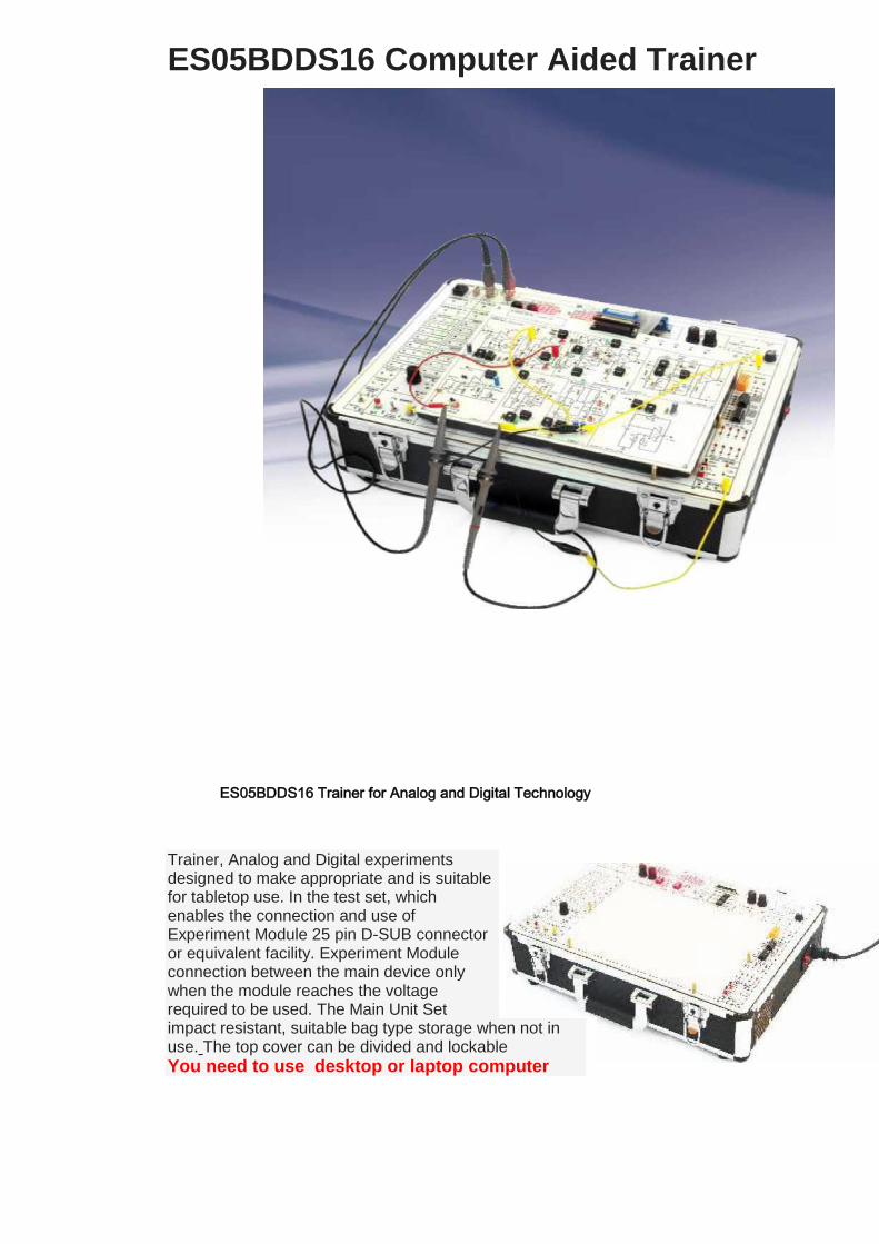
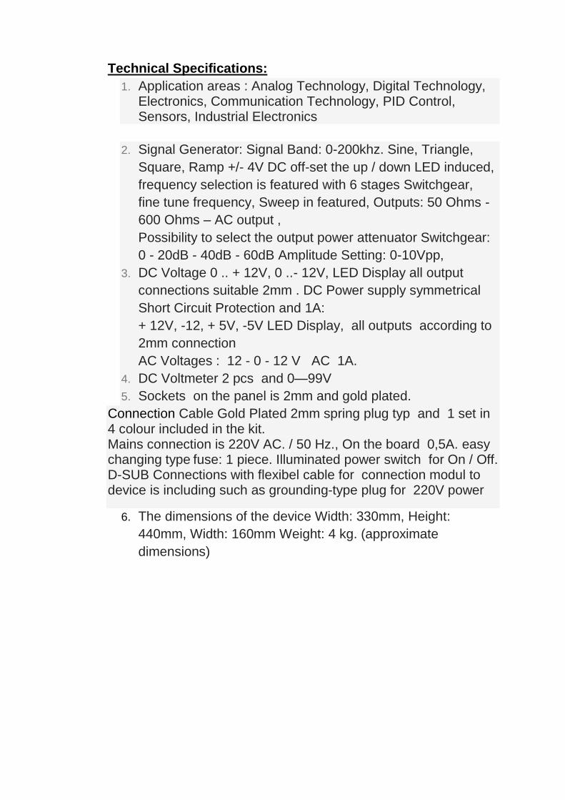
ES05BDDS16 Computer Aided Trainer
ES05BDDS16 Trainer for Analog and Digital Technology
Trainer, Analog and Digital experiments designed to make appropriate and is suitable for tabletop use. In the test set, which enables the connection and use of Experiment Module 25 pin D-SUB connector or equivalent facility. Experiment Module connection between the main device only when the module reaches the voltage required to be used. The Main Unit Set impact resistant, suitable bag type storage when not in use. The top cover can be divided and lockable
You need to use desktop or laptop computer

Interface screen
Trainer consist of: 2 CH 60MHz dijital oscilloscope
Two channels plus an external trigger input. 60 MHz bandwidth with sensitivity from 10mV/division up to 10V/div. 150 MS/s sample rate and 512K sample memory (not at the same time). Wide range of measurements including Vpp, overshoot, rise/fall times, period, frequency, pulse width, spectrum analyser. Main unit included 2 x oscilloscope measuring prob 1:10
Function Generator 1Hz to 100KHz. Sine, Triangle, Square, x 0,1 , x10 , 1K, 10K with maus selectable.
Frequence value and signal amplitude value 0-10Vpp is changed on the screen with the mouse DC Off / Set of +/- 4V as adjusted by the potentiometer on the main unit. Setting the
upper and lower case can be observed with 2 LEDs. Inputs 2mm socket on board
Power supply
DC Power supply: +/- 12V 1 A. Variable , short-circuit protected, Fixed Voltage : +/-12V , +/- Short-circuit protected. All outputs 2mm socket, and LED indicator. AC Voltage : 12V – 0 – 12V common output with fuse and LED control indicator.
Other technical equipment features
Computer aidet 8 relays. Outputs on board 2mm connection On screen 2 x DC Votmeter , 2 x Ampermeter, 1 x Frequancy counter, 16 bit Outputs indicators on screen and on board 16 bit Inputs indicators on screen and on board On the main unit: TTL source SET-CLOCK-RESET outputs Hight/Low/Pulse LED
indicator TTL source 1Hz – 50Hz – 1MHz
Logic Prob : CMOS/TTL/PULSE selectable
Digital Voltmeter inputs 2mm socket
3 x 12V lamps inputs 2mm socket
Included items:
1) ES05BDDS15 Main unit ( Bag typ)
2) 2 x Oscilloscope measuring prob
3) 1 set of 2mm concection cable in 4 colour.
4) Flexibel cable with 2x d-sub connection
5) 220V Power cable.
6) USB Cable
7) Software

ES05BDDS15 Breadboard and
Modules Trainer (Computer Aided )
ES05BDDS15 Electronic Trainer . Developed according to the needs by Basic Level Electronic trainer Set the computer environment monitoring and signal input / output operations capable of a main device Interface consists of experiments with Measuring and Testing Instruments Module. There are also 110mm x 160mm Bread Board for solder less installation process. It is possible to install the modules on the set easily

Technical Specifications: 1. Modular storage (of 13 modules) 2. Oscilloscope 60MHz 2 Channel BNC Connections on board 3. USB connector to PC 4. Computer Interface 5. The computer-controlled 100 MHz Signal Generator, 6. From the computer screen DC voltmeter and DC Ammeter (Digital) ports, has a frequency meter and frequency counter part. 7. Potentiometer Outputs 2mm plug : 10K, 50K, 100K available. 8. DC off-set set, the sine-triangle-square signal from the computer is optional 9. Digital Multimeter on board 10. Bread Board 11. Power Sources: +/- 15V, Current Regulated DC Power Supply 1. Setting value is Digital Voltmeter to display. 0 .. + 15V 1A Adjustable LED indicator Short circuit protection, short circuit protection LED indicator 0 ..- 15V Regulated DC Power Supply Fixed + 12V, -12V, + 5V, -5V DC Power Supply with LED indicator Short circuit protection facility. AC Voltage 12V - 0 - 12V 1A middle point fuse In addition to Bread Board and DC Power Supply Modules: 20V, 15V, 10V, 5V included. 12. Slide Switch 4 pieces 13. 8 Ohm Speaker, Buzzer (piezo) 14. 8-bit switch 15. 2 Button ON: + 5V, OFF: GND is connected. 16. Connection Cable Set in 4 colour. 17. 12V Relay, with 2mm plug to 2 contacts. 18. 2 x 7-segment display .One display have a Integrated driver, the other according to each segment 2mm plug (330 Ohm resistor integrated) 19. LED Indicator 8 pcs. 20. LED 4 serial resistor connected, the anode and cathode side of the appropriate structure 2mm plug. 21. The module assembly area is on board. 22. Experimental Set-top table structure appropriate use, Bags type, the cover is suitable for storing detachable bag. 23. Operating voltage 220V, connected to the network with the grounding cable. Bags side of the light on - off-button and fuse

ES200 DIGITAL TRAINER (Digital Board)
Application: The Digital Trainer is a compact unit for training and exercises and for the practical absorption of knowledge in all fields of basic logical functions, contactless control techniques, digital techniques and computer techniques. Design: The function elements are displayed on the frond panel in form of symbols.The necessary connections (inputs and outputs) are made via 2 mm jacks.Connections are made via 2mm leads of varying lengths. The operating voltage of 5 V. DC, 1A is supplied to the Digital trainer externally via 2mm. jacks. The Digital trainer has a built-in stabilized and short-circuit -proof power supply unit. No additional units are required, as the Digital trainer contains all the necessary digital inputs, logical elements and output functions, including the clock and pulse generator. Inputs and outputs which are not being used need not be connected up.
The units contains the following function groups: • 8 input switches (chatter-free),optical indication of the 'high' status by LED • 1 toggle switch with free connectable contact • 1 button (chatter-free) with Q and Q output • 10 AND/NAND gates, each with 4 inputs • 7 OR/NOR gates, each with 4 inputs • 2AND/OR-NOR gates (combined) each with 2x2 inputs • 1 relay with one switch-over contact

• 5 JK flipflops, with static set and reset inpuls, visual indication of Q conditions by means of LED' s. • 10 indicator lamps (GaAsP - LED' s) • 1 clock generator with 100Hz,50Hz,10Hz,2Hz,1Hz. outputs. • 1 Monoflop with Q and -Q output, triggered by positive or negative edge (Schmitt trigger input) or by means of buttons,pulse width 1....5 micro sec. • 1 decimal counter with BCD outputs. • 1 4 bit full adder • 2 7segment displays with BCD/7 seg. decod. • 2 shift registers (5 digits) with parallel inputs and outputs serial input, reset input, optical indication of the Q - statuses. Examples of experiments
• Analog/digital • Conversion from decimal/binary • Conversion from binary/decimal • Binary variables • Basic logical circuits • Switching algebra • Dual negation • Law of connection • Law of distribution • De Morgan ' s law • Reduction formula • NAND techniques • NOR techniques • Synthesis and analysis of logical circuits • Karnaugh diagram • odes, encoders, decoders, code converters • Stores and time stages • Counters and register circuits • Calculating circuits • Examples of circuits from applied digital techniques
Technical Specification Power connection: 220 AC 50 Hz. Power switch : on/off with pilot light Power supply : 5 V DC , 1 A Stabilized,short-circuits-proof Clock Generatör : 100Hz,50Hz,10Hz,2Hz,1Hz. selectable Integratet: Relay 5 V 1 contac, Button. Dimensions : Length : 470mm ,Width : 330mm , Height : 160mm Weight : approx. 5 kg included in the set: 1 set of connection cable, 5mm short – circuit connentors Manuals in Turkisch or in English CD form. 220V power cable.

ES201 Analog/Digital Trainer
ES201 trainer to meet every need features designed. Basic and Advanced Digital Technology and if necessary Analog Technology performing experiments on the same device It is possible in these products. With the application of Breadboard Module Circuit Development and Circuit Design provides opportunities. Basic and Advanced Training of Digital Techniques are suitable. It is suitable for the following topics: Digital Technology, Analog Technology, Power Electronics, Industrial Electronics, Communications Technologies In Experiment Set located DC voltages Short circuit protection Adjustable 1: 0 .. + 12V, 0 ..- 12V, LED Display All outputs in accordance with 2mm connection Symmetrical Short Circuit Protected Fixed 1: + 12V, -12, + 5V, -5V LED indicator All outputs in accordance with 2mm connection In Experiment Set situated AC Voltages: 12 - 0 - 12 V, Middle out with fuse and LED indicator
Other Features:
Fixed TTL Signal Output: 1Hz, 50Hz, 1MHz
Logic Probe:High: Red LEDLower: Green LEDPulse: Yellow LED

TTL / CMOS Anahrarl of Selection Pulse / Const. Selection Switch TTL Signal Generator (Frequency range DIP switch, fine setting
potentiometer) 10-100-1K-100K-1MHz Stage Pulse Switch: A-B output 4 Data Switches CMOS / TTL Module Connection D-SUB connector 16 LED indicator Thumbwell Switches x1 and x10 1K, 1MOhm 2 potentiometer. Output 2mm plug connection. 2 x 74LS47 integrated 7-segment display, ABCD input in accordance
with 2mm connection 1x 7 segment display each segment 330 Ohm accordance with 2mm
plug out from 1 pcs 8 Ohm Speaker, in accordance with 2mm plug connection
structure 1 pcs Microphone connection structure in accordance with 2mm plug
Supplied accessories include:
1 set of 2mm connection cable, d-sub connector cable, 220V power cable, Additional optional parts: Experiments module (Refer to the module list for , Digital Technology, Analog Technology, Power Electronics, Industrial Electronics, Communications Technologies) Can be use with Breadboard module or others modules

ES04.10 Bread Board Design - Trainer ES04.10 Trainer is a bag typ and suitable for table-top use. Set have on the middle part of a large, solder less perforated panels, designed for installation operations (Bread Board) Available properties: TTL signal output: Switch elective 5Vpp Digital Display: 2 digital voltmeter 2mm connection input potentiometer 4 pieces: 1K, 10K, 100K, 1M Ohms. 1 Piece Toggel Switch On / Off 1 Piece Button (on the pressure) 3 Piece 3 with 2mm short circuit terminal 1 piece 5V relay connections 2mm 2 Piece 7 Segment Display 8-bit LED display 8 Slide Switch 2 BNC connection socket ( For oscilloscope) Technical Data: DC voltages : Short circuit protection Adjustable : 0 .. + 12V, 0 ..- 12V, 1 A. LED indicator. All outputs are short circuit protected in accordance with 2mm connection Fixed : 1 A. + 12V, -12, + 5V, -5V LED indicator

AC Voltages: 1A. 12 - 0 - 12 V AC Signal Generator: Signal Band: 0-200 Hz. Sine, Triangle, Square, Ramp. +/- 4V DC off-set the up / down LED stimulated with Switchgear in 6 Step Frequency featured selection, frequency fine-tuning, Sweep in featured, Outputs: 50 Ohms - 600 Ohms - AC, output power attenuator The possibility to choose the commutator: 0 - 20dB - 40dB - 60dB Amplitude adjustment: 0-10Vpp, Working status LED indicator light TTL signal output: Switch elective 5Vpp Digital Indicators: 2 digital voltmeter 4 pcs 2mm connection potentiometer input: 1K, 10K, 100K, 1M Ohms. 1 Piece Togliani Switch On / Off 1 Piece Button (on the pressure) 3 Piece 3 with 2mm short circuit terminal 1 piece 5V relay connections 2mm 2 Piece 7 Segment Display 8-bit LED display 8 Switch 2 BNC connection socket Specifications All outputs in accordance with 2mm connection The dimensions of the device Width: 330mm, Height: 440mm, Width: 160mm Weight: 4 kg. Mains connection 220V AC. / 50 Hz., on panel fuse: Illuminated Power Switch On / Off switch ES04.10 Breadboard use only. Not suitable for modules
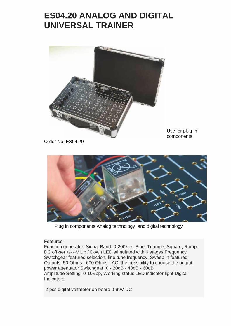
ES04.20 ANALOG AND DIGITAL UNIVERSAL TRAINER
Use for plug-in components
Order No: ES04.20
Plug in components Analog technology and digital technology
Features: Function generator: Signal Band: 0-200khz. Sine, Triangle, Square, Ramp. DC off-set +/- 4V Up / Down LED stimulated with 6 stages Frequency Switchgear featured selection, fine tune frequency, Sweep in featured, Outputs: 50 Ohms - 600 Ohms - AC, the possibility to choose the output power attenuator Switchgear: 0 - 20dB - 40dB - 60dB Amplitude Setting: 0-10Vpp, Working status LED indicator light Digital Indicators 2 pcs digital voltmeter on board 0-99V DC

3 Phase Voltage AC output :L1, L2 - L3 N 3x7V AC between 2 phases 12V AC
1 Speaker 4 Total 4 / 2mm adapter terminal For OP-AMP 2mm +/- 15V connector, and 4 groups according to the short-circuit plug 4mm mounting panel total 45 groups DC Power supply: Short circuit protection Adjustable : 0 .. + 15V, 0 ..- 15V, 1A.LED Display All outputs in accordance with 4mm connection Symmetrical Short Circuit Protected Fixed + 15V, -15, + 5V, -5V 1A. LED Display . All outputs in accordance with 4mm connection AC : 12V – 0 12V AC 1A.
The dimensions of the device Width: 330mm, Height: 440mm, Width: 160mm Weight: 5 kg. Mains connection 220V AC. / 50 Hz., on panel fuse : Illuminated Power Switch On / Off
ACCESSORY SETS 1. Order No: EK1: BASIC ANALOG CIRCUITS 2. Order No: EK2 : FUNDEMENTALS OF ELECTRONICS AND BASIC ANALOG CIRCUITS 3. Order No: EK 3 : BASIC DIGITAL CIRCUITS 4. Order No: EK 4 : DIGITAL DATA PROCESSING

1. EK1: BASIC ANALOG CIRCUITS (Plug-in components) This experiments that can be performed with the set : A) Direct Current Technology Simple electrical circuits Ohm' s law FU and FI protection circuit Electrical resistors NTC PTC Varistor VDR LDR Series and Paraller circuiting of resistors Voltage divider B) Alternating Current Technology Establishing and displaying characteristics in AC technology Star circuits Delta circuits Capacitor in the AC circuit Series and Parallel circuits of capacitors Coil in the AC circuit Series and Parallel circuiting of coils RC,LC,LC Series and Parallel circuiting C) Semiconductor components Diodes Transistors Thyristors Diac Triac Basic ındustrial electronics circuits (All components are in plastic box and have 4mm pins) 2. EK2 : FUNDEMENTALS OF ELECTRONICS AND BASIC ANALOG CIRCUITS This experiments that can be performed with the set : A) Electronic components RESISTORS: -Linear resistors,Trimmers,Non-linear resistors, -PTC,NTC,Voltage-dependent resistors (VDR) CAPACITORS: -Types of construction,Electrolytic capacitors, -Metallized-paper capaciors,Metallized-plastic -capacitors,Ceramic capacitors,Circuits with -capacitors and resistors. OHM'S LAW SEMICONDUCTOR DIODES: -Doping of Semiconductors,Diodes,Application TRANSISTORS: -Bipolar transistors,unipolar transitors COMPONENTS WITH BISTABLE CHARACTERISTICS
-Unijunction-transistor, Thyristor OPTOELECTRONIC COMPONENTS:

-Potoelectric emission,LDR,LED,Phototransistor, optocouplers B)Analog practice Basic diode circuits Rectification,voltage stabilization and multiplication Diode as switch (rectifier) Basic transistor circuits Transistor as switch,bounce-free switch Transistor as variable resistor Transistor as amplifier,coupling facilities Transistor in current and voltage stabilization Voltage conversion Electronic fuse Schmitt-Trigger Oscillator circuits with transistors Aplication of field-effect transistors(FET) Aplication of components with bistable characteristics Power supply circuits Examples of applications as switch Optoelectronic components, application Operational amplifier Inverting and non - inverting circuits Integrated voltage controllers Integrated timer circuits 3. EK 3 : BASIC DIGITAL CIRCUITS Basic operations,description of all the modules Master-Slave bistable circuit with following bistable elements: RS-,JK-, D-, and T, monostable,astable, and bistable flip-flops. Switching mechanisms, synchronous and asychronous Aritmetic functions Algebraic reduction methods to the 1st,2nd,3rd and 4th order.Graphic reduction methods. 4. EK 4 : DIGITAL DATA PROCESSING Coders, decoders, recoders Counters and their application Asynchronous dual counters Synchronous dual counters Modulo N counters, BCD counters Counter application Registers and their application Memories Shift registers Basic phase-locked loop circuits Mathematical treatment of digital PLL circuits Application of PLL circuits Analog/digital conversion,application 2-quadrant multiplier with 2 A/D converters Divider with the aid of two A/D converters Digital/Analog conversion with the aid of R/2R netw. Digital arithmetic logig unit Adder,subtracter,mutiplier Comparator,bit shift of data Examples of data processing circuits Multiplex practice
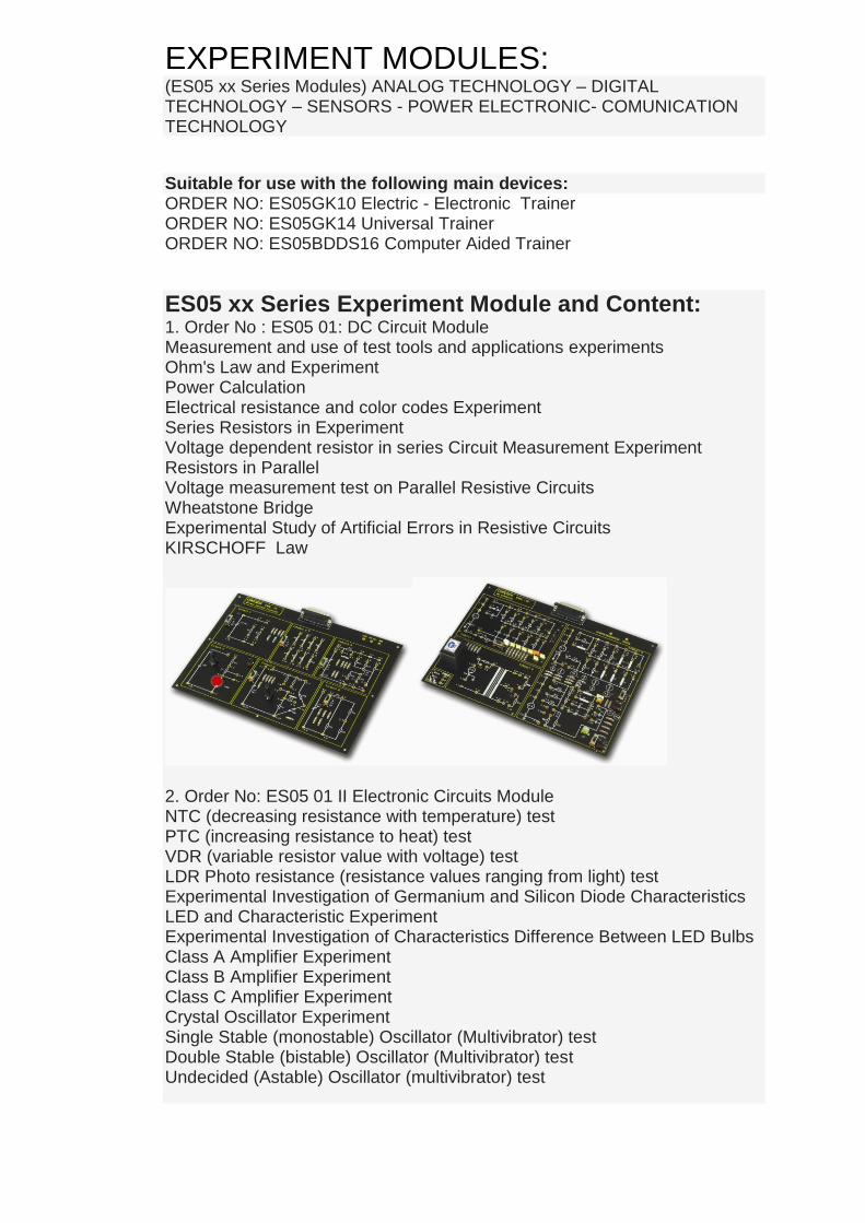
EXPERIMENT MODULES: (ES05 xx Series Modules) ANALOG TECHNOLOGY – DIGITAL TECHNOLOGY – SENSORS - POWER ELECTRONIC- COMUNICATION TECHNOLOGY
Suitable for use with the following main devices: ORDER NO: ES05GK10 Electric - Electronic Trainer ORDER NO: ES05GK14 Universal Trainer ORDER NO: ES05BDDS16 Computer Aided Trainer ES05 xx Series Experiment Module and Content:
1. Order No : ES05 01: DC Circuit Module Measurement and use of test tools and applications experiments Ohm's Law and Experiment Power Calculation Electrical resistance and color codes Experiment Series Resistors in Experiment Voltage dependent resistor in series Circuit Measurement Experiment Resistors in Parallel Voltage measurement test on Parallel Resistive Circuits Wheatstone Bridge Experimental Study of Artificial Errors in Resistive Circuits KIRSCHOFF Law
2. Order No: ES05 01 II Electronic Circuits Module NTC (decreasing resistance with temperature) test PTC (increasing resistance to heat) test VDR (variable resistor value with voltage) test LDR Photo resistance (resistance values ranging from light) test Experimental Investigation of Germanium and Silicon Diode Characteristics LED and Characteristic Experiment Experimental Investigation of Characteristics Difference Between LED Bulbs Class A Amplifier Experiment Class B Amplifier Experiment Class C Amplifier Experiment Crystal Oscillator Experiment Single Stable (monostable) Oscillator (Multivibrator) test Double Stable (bistable) Oscillator (Multivibrator) test Undecided (Astable) Oscillator (multivibrator) test

3.Order No: ES05 02: AC Circuits Module Benchmarks with Oscilloscope Resistance Measurement Test in AC Current and Voltage Phase Angle Experiment in Resistance in Alternating Current Circuits Series Resistors Circuit Experiment in Alternative Parallel Resistance Experiment in Alternative Assets Capacity Test in square and sine AC circuit Change Experiment with capacitive reactance and frequency Capacitive reactance capacity Effect of Change of Value Test AC circuit connected in parallel Capacity Test AC circuit connected Capacity Test Series AC voltage divider circuit as a Work Capacity Test AC circuit inductance Effect of changing inductance value of the inductive reactance Experiment AC circuit Test Series Resistors and Capacitors Parallel Resistors and Capacitors AC circuit experiment AC circuit Test Series Resistors and Inductors AC circuit Parallel Resistance and Inductance Test High Pass and Low Pass Filters Resistance and Capacity Filter Circuit Experiment Resistance and inductance Filter Test Parallel LC Experiment at Low Impedance AC Circuits Error Study of Resonance Circuit Experiments Parallel LC Experiment at High Impedance AC Circuits R-L-C circuit Transformers and Transformers Under Load Test Under Load Current Transformer in Secondary Measurement Experiment
5. Order No: ES05 04: Semiconductors Experiment Module All Transistor (NPN and PNP type) Study of the Double Darlington Transistor Difference (Differential) Amplifier Experiment JFET (Field Effect) Transistor Characteristics Experiment With JFET Analog Switching Direct Coupled Amplifier Experiment
6. Order No: ES05 05: DC Power Supplies Experiment Module Half Wave Rectifier Experiment Full Wave Rectifier Experiment Straightening Under Load Test Test Filter capacitor Zener Diode Test Balancing the Zener Diode and Transistor Test Over Current Protection
Overvoltage Protection Symmetric DC Voltage Source Experiment Obtained with Integrated Voltage Regulator Test Obtained Adjustable Voltage Regulator with Integrated Test AC / DC Converters Test DC / DC Converters Fixed Output Test DC / DC Converter Adjustable Experiment SMPS Switched (Switchmode) Regulator Circuit Test Switching Technique Experiment Switching Accelerator (Boost) Technical Experiment
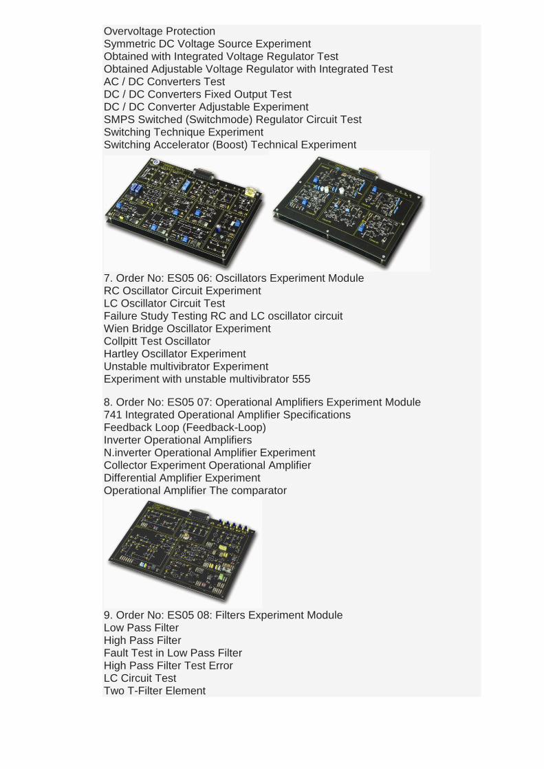
7. Order No: ES05 06: Oscillators Experiment Module RC Oscillator Circuit Experiment LC Oscillator Circuit Test Failure Study Testing RC and LC oscillator circuit Wien Bridge Oscillator Experiment Collpitt Test Oscillator Hartley Oscillator Experiment Unstable multivibrator Experiment Experiment with unstable multivibrator 555
8. Order No: ES05 07: Operational Amplifiers Experiment Module 741 Integrated Operational Amplifier Specifications Feedback Loop (Feedback-Loop) Inverter Operational Amplifiers N.inverter Operational Amplifier Experiment Collector Experiment Operational Amplifier Differential Amplifier Experiment Operational Amplifier The comparator
9. Order No: ES05 08: Filters Experiment Module Low Pass Filter High Pass Filter Fault Test in Low Pass Filter High Pass Filter Test Error LC Circuit Test Two T-Filter Element

Load and operational amplifier circuit Filter Operational Amplifier with Filter Attenuation (attenuation) t United Filter High and Low Pass Filters Parallel Filter
10. Order No: ES05 09: Power Electronics (I) Experiment Module Experimental Study of Power Transistor Working with MOSFET Transistor MOSFET transistors Error Study Experiment Working with Tristar Experiment Experimental Study of the thyristor error Triggering Experiment in thyristors UJT Circuit Insulation (insulation) Working with Circuit Experiment Triac (TRIAC) Circuit Experiment Practical experiments with Triac Diac (Diac) Behavior Experiment 11. Order No: ES05 11 09 II. Power Electronics Experiment Module The 4017 Integrated PWM (Pulse Width Modulation) Pulse Amplitude Modulation Experiment Experiment with the integrated PWM 555 DC Power Control Experiment Motor Speed Control Experiment
12.Order No: ES05 09 III. Power Electronics Experiment Module UJT (Uni Junction Transistor) PUT (Programable Uni Junction Transistor) Characteristic Experiment PUT Test Oscillator SUS (Silicon Unilateral Switch) Characteristic Experiment SUS Test Oscillator SCSI (Silicon Controlled Switch) Test
SCSI Test Oscillator PNPN diode Characteristic PNPN diode Oscillator Experiment SCR (Silicon Controlled Rectifier) Characteristic Experiment SCR with Control Experiment Triac (TRIAC) with AC Power Control Experiment
13. Order No: ES05 13 09 IV. Power Electronics Experiment Module Automatic Controlled Experiment lamp with op.amp Triac (Triac) and Automatic Controls Lamp Test Turn-on Timer Test Turn-off timer Experiment 14. Order No: ES05 10 Digital Technology Experiment Module 1. Analog Logic Gates Characteristics Experiment Experimental Study of Artificial Fault Circuit Analog Multiplexers S-R type Circuit Characteristic Experiment Characteristic of unstable Circuit Experiment Unstable Enable Error Study Experiment Single-State Characteristics of Integrated Circuits Experiment Decimal Counter Behavior of Circuit Experiment and 7 Segmetl Indicator Bidirectional Binary Coded Decimal Counter and 7 Segment Analog Comparator Characteristics Integrator Analog Triangle Test Signal Generation D / A (digital / analog) converter (inverter) A / D (Analog / Digital) converter (inverter) Random (Astable) Number Generator Test
15. Order No: ES05 11 Digital Technology Experiment Module 2. Indicators (Indicators) Experiment Logic Circuit with transistor and diode test Fundamental Experiments OR-AND-NOT gate CMOS Gate Tests Boolean Algebra and Logic Gate Function Test Schmitt Trigger Inverters With Simple Operation Test Three-state buffer with Operation Test 16. Order No: ES05 12 Digital Technology Experiment Module 3 Encoder and Decoder Circuit Circuit Test Experimental Study of Artificial Error Decoder Circuits Multiplexer (MUX) test Demultiplexer (DEMUX) Assay Demultiplexer circuit Artificial Error Study Experiment Comparator (Comp.) Test Experimental Study of Artificial error comparator circuit Adder (Adder) test Parity Circuit Experiment Experimental Study of Artificial Error Parity Generator Circuit

17. Order No: ES05 13 Digital Technology Experiment Module 4 Sequential Systems, Logical Resources and Logical Screen (Sources Logic and Logic Displays) Nor gated S-R two-state Shift Registers Counting Artificial Error Operation of Counter Circuit Simultaneous Bidirectional Counter 18. Order No: ES05 14 Optical Circuit Elements Experiment Module LCD Liquid Crystal Display 7-segment Indicative LED LDR (light-variable resistance value) Fiber optic test IR (Infared)
19.Order No: ES05 15 Bread Board (Solderless installation) Module Making connections through the power supply circuit design points, Bread board for use
20. Order No: ES05 15 .02 Experiment Module 150mm x 200mm D Bread Board basic level circuit design process
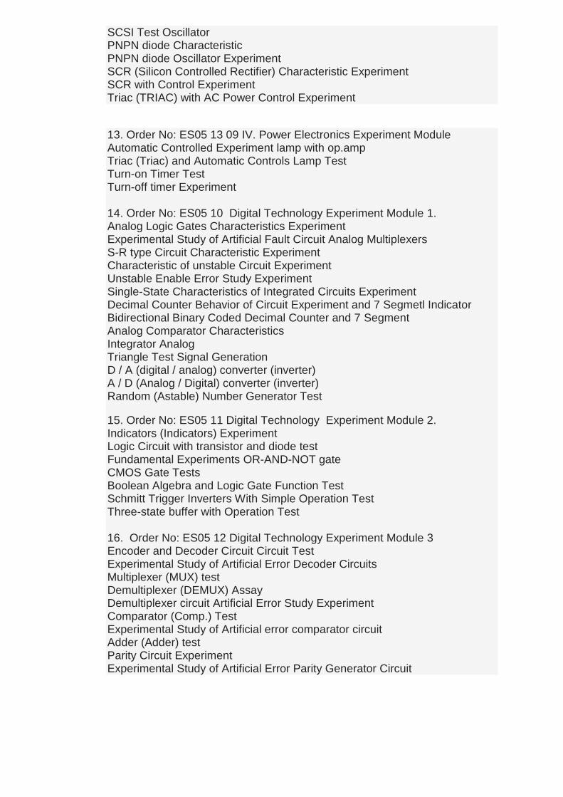
21. Order No: ES05 16 Electrical Networks Experiment Module Ohm's Law The presence of the internal resistance of a current source The presence of the internal resistance of an AC source DC no load test of the electrical power used on the circuit The presence of electrical power used on the AC circuit load The electrical power delivered to the load from the AC power source Power supplies connected together Together connecting to the power supply in Thevenin's and Norton's theorems experiments Star, Triangle circuit analysis experiments Wheatstone bridge experiment D. a WHEATSTONE measuring bridge supplied from the source Artificial experiments in the Wheatstone bridge circuit fault From a.a. source that WHEATSTONE measuring bridge
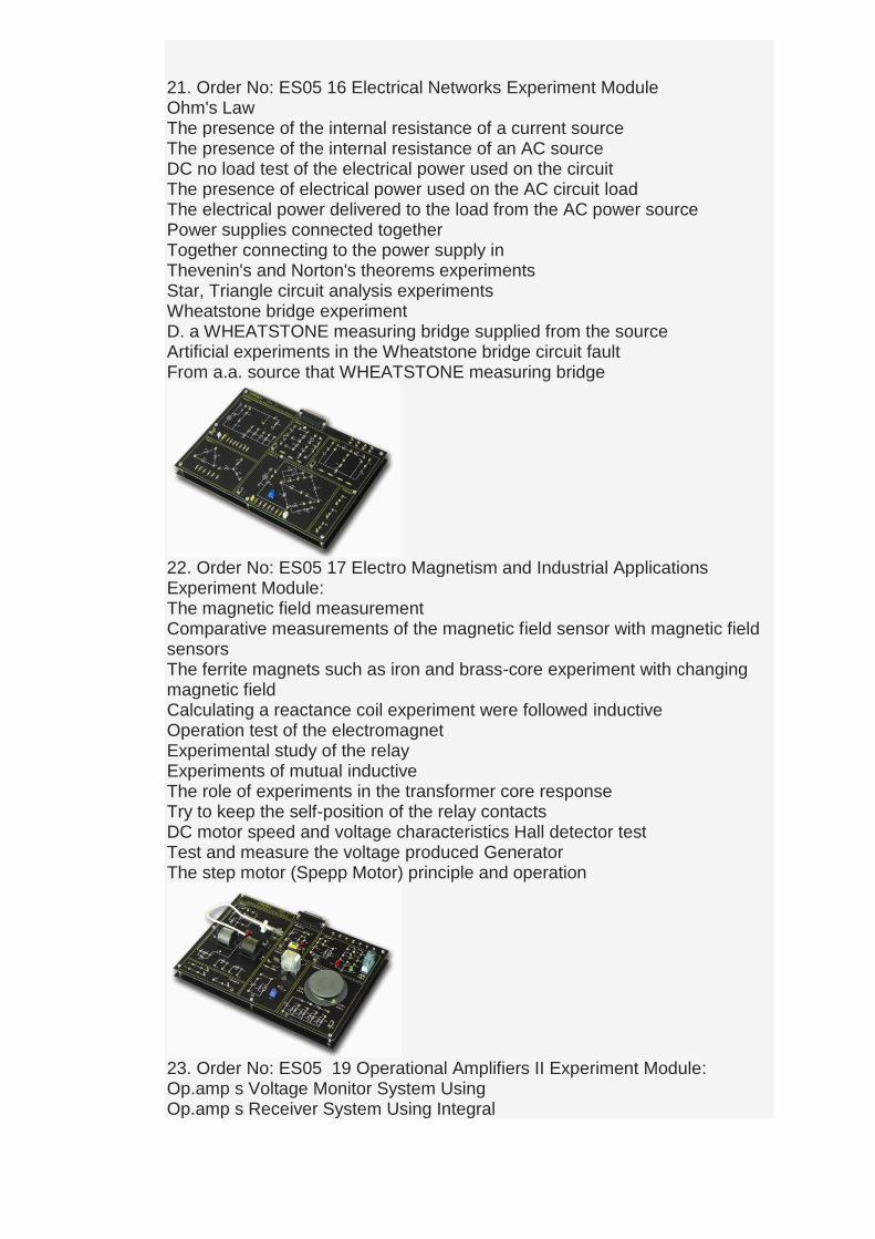
22. Order No: ES05 17 Electro Magnetism and Industrial Applications Experiment Module: The magnetic field measurement Comparative measurements of the magnetic field sensor with magnetic field sensors The ferrite magnets such as iron and brass-core experiment with changing magnetic field Calculating a reactance coil experiment were followed inductive Operation test of the electromagnet Experimental study of the relay Experiments of mutual inductive The role of experiments in the transformer core response Try to keep the self-position of the relay contacts DC motor speed and voltage characteristics Hall detector test Test and measure the voltage produced Generator The step motor (Spepp Motor) principle and operation
23. Order No: ES05 19 Operational Amplifiers II Experiment Module: Op.amp s Voltage Monitor System Using Op.amp s Receiver System Using Integral

Op. Amp use derivatives as recipient Experiment Op. Amp Timer (Timer) Op. Amp s Half Wave Rectifier System Using Op. S Full Wave Rectifier Amp System Using Op. Amp s High Pass Filter System Using Op. Amp s Bisabl the (stable) Multivibrator SR-Flip-Flop Using Op. Amp Voltage / Current Converter
24.Order No: ES05 21 RAM - EEPROM Experiment Module Ram Memory Saving Information Saving Data EEPROM Memory Ram Memory of Information Reading Reading the Data EEPROM Memory
25. Order No: ES05 22 ALU Experiment Module Half Adder Experiment Application Full Adder Experiment Application Parallel Benchmarks for Collectors Half Remover Practice Tests Full Remover Experimental Practice Parallel experiments Remover Application 74LS181N Integrated Collection of Subtracting Experiment Series Collector / Remover Application Experiment Multiplication Test Application Partition Test Application Procedure
26. Order No: ES05 23 Transformers Experiment Module To measure the current in the transformer short circuit

Short-circuit voltage measured at the transformer Measurement of short-circuit the transformer Copper Loss 27. Order No: ES05 25 Digital Circuits Experiment Module Digital / Analog (D / A) and analog / digital (A / D) converters (ADC, DAC) Experiment with Integrated Oscillator 555 7 Segment Display (Display) is driven by the 7447 experiment DOT Matrix Display
28. Order No: ES05 26 Hi-Fi Stereo Amplifier (2 x 10W) Experiment Module AF Pre-Amplifier (Preamplifier) AF Pre-Amplifier (Preamplifier) try to find fault Output stages of the Right and Left Channel Channel and try to find artificial fault circuit on the circuit Balance, Treble, bass, volume (Volume) settings tracking experiments Faults and causes experiments
29. Order No: ES05 27-1 Sensor Experiment Module: NTC sensor PTC sensor Bimetal Photo transistor Opto-couplers Photo diode test Thermocouple Reed Relays Humidity Sensor Thermocouple
30. Order No: ES05 27-2 Sensor Experiment Module To the piezo electric element Solar cell (photovoltaic) Hall effect experiment P (motion) sensor test Microphone Mercury switches LED test gas sensor,

31. Order No: ES05 27-3 Sensor Experiment Module Optical sensor probe Capacitive sensor Inductive sensor 32. Order No: ES05 27-4 Sensor Experiment Module IR LED assay switch Piezo sensor Ultrasonic sensor Distance sensor t LoadCell Vibration Sensor 33.Order No: ES05 28 Electronic Circuits Experiment Module RC Phase Shift Oscillator Circuit Experiment Wien Bridge PNP-NPN transistor characteristics Low Pass, High Pass Filter 34. Order No: ES05 29 Electronic Circuits Experiment Module Op Amps with a single stable Harmonic Oscillator (monostable Oscillator) Tape Op Amp Comparator with Voltage Op - Amp Instrumentation Amplifier Op Amp with Tone (sound) Control experiment Noise Generator Adjustable Pulse Oscillator. Schimitt Oscillator Metronome
35. Order No: ES05 30 Electronic Circuits Experiment Module Crystal Oscillator Experiment Traffic Lights Experiment Level Control Experiment LDR and LED Characteristics RC coupling (linked) amplifier Experiment Transformer coupling (linked) amplifier Experiment FET Characteristics Experiment FET Amplifier Test Common Resources FET Common Channel
36. Order No: ES05 31Digital Circuits Experiment Module From 1-bit to 2-bit encoder / multiplexer 4 bit coding of 2 bits 10-bit coding of 4 bits 4 bits to 9 bits coding 8 to 1 multiplexer 1 to 8 multiplexer decoder
37. Order No: ES05 32 Experiment Module Op-amp circuit 741 tests

Asabl to, bistable, monostable vibrator experiments N-channel FET transistor t P-channel transistor Signal source sine / square / triangle production A-B-C type amplifier experiments Try to run counter to the 7490 integrated Diyot- zener diode characteristic
38. Order No: ES60 PID Experiment Module Proportional Delay Systems Integral System Experimental Investigation of derivative System P Control Experiment PI Controller Experiment Two-Point Control Limiting Two-Point Control Realization of Control PI Control Unit with Speed Control Test (Motor Board Module Required)
Black or White available color selection
COMMUNICATIONS TECHNOLOGY MODULES: Suitable for use with the following main devices: ORDER NO: ES05GK10 Electric - Electronic Trainer ORDER NO: ES05GK14 Universal Trainer ORDER NO: ES05BDDS16 Computer Aided Trainer 39. Order No: ES400-1200.2 FM / AM Radio Transmitter Experiment Module 40. Order No: ES400-1200.3 FM / AM Radio Receiver Experiment Module 41. Order No: ES400-1300 Experiment Module Fiber Optic Transmitter 42. Order No: ES400-1301 Experiment Module Fiber Optic Receiver 43. Order No: ES400-1501 (AM) Amplitude Modulation / Demodulation 44. Order No: ES400-1502 (FM) Frequency Modulation / Demodulation 45. Order No: ES400-1504 (PWM) Pulse Width Modulation / Demodulation
46. Order No: ES400-1506 (FSK) Frequency Shift Keying Modulation / Demodulation 47. Order No: ES400-1507 (PSK) Phase Shift Keying Modulation / Demodulation 48. Order No: ES400-1509 (PCM) Pulse Code Modulation / Demodulation 49. Order No: ES400-1558 (ASK) Amplitude Shift Keying Modulation / Demodulation 50. Order No: ES400-1560 (QPSK) Modulation/ Demodulation 51. Order No: ES400-1561 (DSB-SSB) and Single Side Band Double Side Band Modulation / Demodulation 52. Order No: ES400-1700 Phone Device 53. Order No: ES400-1717 High Pass Filter, Low Pass Filter 54. Order No: ES400-1720 Wireless Communication Filters 55. Order No: ES400-1730 TDM multiplexer / demultiplexer 56. Order No: ES400-1740 FDM multiplexer / demultiplexer 57. Order No: ES400-1750 Frequency Converter / Frequency Multiplier 58. Order No: ES400-1760 PLL (Phase Locked Loop) 59. Order No: ES400-1800 CVSD & Manchester Encoder / Decoder 60. Order No: ES400-1901 Oscillators