Embed Size (px)
Citation preview

AC Servo Motor Driver
LJ1H20
90
Slider TypeHigh Rigidity
Max. work load: 85 kg
Positioning repeatability: ±0.02 mm
Max. acceleration/deceleration: 20000 mm/s2
Max. stroke: 3000 mm
Max. speed: 3000 mm/s
Max. acceleration/deceleration: 20000 mm/s2
Ball Screw Drive Series LEJS
Belt Drive Series LEJB
Size: 40, 63
Size: 40, 63
Series LECSA
TypeAC Servo Motor
LEJS40
58
Low-profile/Low centre of gravityHeight dimension reduced by approx. 36% (Reduced by 32 mm)
Pulse input type/Positioning type
Series LECSBPulse input type
Series LECSC
CC-Linkdirect input type
Series LECSSSSCNET III type
Incremental Type Absolute Type
LEJS40
LJ1H20
55
30(Existing model)
Series Work load [kg]
600
500
Speed [mm/s]
100
100
Motor output [W]
NewNew
Electric Actuator
CAT.EUS100-104B-UK
Series LEJ
NewNewRoHS

0.02
0.01
00 100 200 300 400 500D
ispl
acem
ent [
mm
]
Load W [N]
W
L
Ball Screw Drive/Series LEJS
Belt Drive/Series LEJB
Series LEJ
�Reduction of the installation labourPossible to mount the main body without removing the external cover, etc.
�Workpiece does not interfere with the motorTable height > Motor height
�Weight reductionWeight reduced by approx. 37%∗ Stroke: 600 mm
�High precision/High rigidityDouble axis linear guide reduces deflection
Equipped with seal bands as standardCovers the guide, ball screw and belt. Prevents grease from splashing and external foreign matter from entering.
AC Servo Motor
Tab
le h
eigh
t
Mot
or h
eigh
t
Motor
Workpiece
Linear guide (Double axis)
Table
Table displacement∗ LEJ�63: L = 64.5 mm
Belt
He
igh
t
Slider type withlower height
He
igh
t
Slider type withlower height
Offering 2 types of motor cable
�Standard cable�Robotic cable (Flexible cable)
Non-magnetizing lock (Option)
Holding a workpiece
Positioning pin hole
Ball screwLinear guide (Double axis)
Holding a workpiece
Non-magnetizing lock (Option)
LEJS63
LJ1H30 24.0 kg
15.2 kg 37%
Features 1

Application Examples
Series VariationsBall Screw Drive/Series LEJS
Belt Drive/Series LEJB
∗ Consult with SMC as all non-standard and non-made-to-order strokes are produced as special orders.
∗1 Consult with SMC as all non-standard and non-made-to-order strokes are produced as special orders.∗2 The belt drive actuator cannot be used vertically for applications.
Size
40
63
Page
Page
8
16
10
20
Work load: Horizontal [kg] Work load: Vertical [kg] Speed [mm/s]Lead[mm] Stroke [mm]∗ 10 20 30 10 20 200 400 600 800 100040 50 60 120070 80 90
300, (400), 500600, (700), 800
(900), 1000(1200), (1500)
200, 300, (400)500, 600, (700)
800, (900)(1000), (1200)
Size
Page 9
Page 14
40
63
27
42
Work load: Horizontal [kg]∗2Equivalent lead
[mm] Stroke [mm]∗1
(200), 300, (400), 500, (600), (700), 800(900), 1000, (1200), (1500), (2000)
(300), (400), 500, (600), (700), 800(900), 1000, 1200, (1500), (2000), (3000)
105 15 20 25 30Speed [mm/s]
500 1000 1500 2000 2500 3000
30
Electric Actuator/High Rigidity Slider Type
�Solid state auto switch can be mounted (For checking the limit and intermediate signal)� Switch wiring can be placed in the body� D-M9�W (2-colour indication), D-M9�
Auto switch
Wiring
Operating range OFFON
Red Green Red
Optimum operating range
2-colour indication solid state auto switchAppropriate setting of the mounting position can be performed without mistakes. Operating rangep g g
R
O
d without mistakes.
Recommended driver: LECS� Recommended driver: LECSS(SSCNET III)
Glue dispensing/High speed trajectory is availablePick and place
LECSA LECSB LECSC LECSS
A green light
lights up at the optimum operating range.
Features 2

Note 1) For positioning type, setting needs to be changed to use with maximum set values. Setup software (MR Configurator) LEC-MR-SETUP221 is required.Note 2) Available when the Mitsubishi motion controller is used for the master equipment.
Note 1)
PositioningNote 2)
SynchronousPulseNetwork
directinput
Control method Application/Function
Compatible motor(100/200 VAC)
Setup softwareLEC-MR-SETUP221
Compatibleoption
100 W 200 W
LECSA(Pulse input type/Positioning type)
LECSB (Pulse input type)
LECSS (SSCNET III type)Compatible with Mitsubishi Electric’s servo system controller network
LECSC (CC-Link direct input type)
Series LECS� list
Up to7 points
Up to255 points
CC-LinkVer. 1.10
SSCNET III
AC Servo Motor Driver
Series LEJ
Incr
emen
tal T
ype
Ab
solu
te T
ype
Features 3

Spe
edTime
Settlingtime
Spe
ed
Time
Settlingtime
Electric Actuator/High Rigidity Slider Type
Servo adjustment using auto gain tuning
With display setting function
Auto resonant filter function
Auto damping control function
One-touch adjustment button
Display
Settings
Display
Settings
Display
Settings
LECSALECSB
Display
Settings
LECSSLECSC
Series LECS�
Features 4

System Construction
Series LEJ
Driver
DriverAbsolute encoder compatible Series LECSB
Power supply for I/O signal
24 VDC
Power supplySingle phase 100 to 120 VAC (50/60 Hz) 200 to 230 VAC (50/60 Hz)
Provided by customer
Battery (Accessory)
PC
Setup software
PC
Setup software
(MR ConfiguratorTM)Part no.: LEC-MR-SETUP221E
Part no.: (LEC-MR-J3BAT)
Provided by customer
Provided by customer
Power supplySingle phase 100 to 120 VAC (50/60 Hz) 200 to 230 VAC (50/60 Hz)
Three phase 200 to 230 VAC (50/60 Hz)
Provided by customer
Control circuit power supply24 VDC
Motor cable Page 36
Page 36
Page 36
Page 36
Page 36
Page 37
Page 37
Page 36
Page 37
Page 37
Page 37
Analogue monitor output
USB cablePart no.: LEC-MR-J3USB
Lock cable
Encoder cable
Provided by customer
PLC (Positioning unit)
Power supply for I/O signal
24 VDC
PLC (Positioning unit)
(Pulse input type)
Incremental encoder compatible Series LECSA(Pulse input type/Positioning type)
Standard cableLE-CSM-S��
Robotic cable
LE-CSM-R��
Standard cable Robotic cableLE-CSB-S�� LE-CSB-R��
Standard cable Robotic cableLE-CSE-S�� LE-CSE-R��
(MR ConfiguratorTM)Part no.: LEC-MR-SETUP221E
∗ Order USB cable (Part no.: LEC-MR-J3USB) separately to use this software.
USB cablePart no.: LEC-MR-J3USB
Option
Motor cableStandard cable Robotic cableLE-CSM-S�� LE-CSM-R��
Lock cableStandard cable Robotic cableLE-CSB-S�� LE-CSB-R��
Electric actuatorHigh rigidity slider typeSeries LEJ
Electric actuatorHigh rigidity slider typeSeries LEJ
Encoder cableStandard cable Robotic cableLE-CSE-S�� LE-CSE-R��
Option
∗ Order USB cable (Part no.: LEC-MR-J3USB) separately to use this software.
RS-422 communication
Main circuit power supply connector(Accessory)
Page 31
Part no.: LEC-MR-RB-�Regeneration option
Option Page 36 Control circuit power supply connector(Accessory)
Page 30
I/O connectorPart no.: LE-CSNA
Option Page 36
Part no.: LEC-MR-RB-�Regeneration option
Option Page 36
Control circuit power supply connector(Accessory)
Page 31
Motor connector(Accessory)
Page 31I/O connectorPart no.: LE-CSNB
Option Page 36
Main circuit power supply connector(Accessory)
Page 30
Features 5

System Construction
Electric Actuator/High Rigidity Slider Type
Driver
Battery (Accessory)
PC
Setup software(MR ConfiguratorTM)Part no.: LEC-MR-SETUP221E
Part no.: (LEC-MR-J3BAT)
Provided bycustomer
Power supplySingle phase 100 to 120 VAC (50/60 Hz) 200 to 230 VAC (50/60 Hz)
Three phase 200 to 230 VAC (50/60 Hz)
Provided by customer Option
Option
Option
Option
Power supply for I/O signal24 VDC
PLC (CC-Link master unit)
Electric actuator
CC-Link connector(Accessory)
Driver
Battery (Accessory)
PC
Setup software(MR ConfiguratorTM)Part no.: LEC-MR-SETUP221E
Part no.: (LEC-MR-J3BAT)
Providedby
customer
Power supplySingle phase 100 to 120 VAC (50/60 Hz) 200 to 230 VAC (50/60 Hz)
Three phase 200 to 230 VAC (50/60 Hz)
Provided by customer
Power supply for I/O signal
24 VDC
PLC (Positioning unit/ Motion controller)
Electric actuatorCN1A
CN1B
CN1A
Absolute encoder compatible Series LECSC(CC-Link direct input type)
Absolute encoder compatible Series LECSS(SSCNET III type)
Page 36
Page 36
Page 36
Page 36
Page 36
Page 36 Page 37
Page 37
Motor cableStandard cable Robotic cableLE-CSM-S�� LE-CSM-R��
Lock cableStandard cable Robotic cableLE-CSB-S�� LE-CSB-R��
Encoder cableStandard cable Robotic cableLE-CSE-S�� LE-CSE-R��
USB cablePart no.: LEC-MR-J3USB
Page 37
Page 37
RS-422 communication
Motor cable
Lock cable
Standard cable Robotic cableLE-CSM-S�� LE-CSM-R��
Standard cable Robotic cableLE-CSB-S�� LE-CSB-R��
Encoder cableStandard cable Robotic cableLE-CSE-S�� LE-CSE-R��
Page 37
Page 36
Page 36
Page 37
USB cablePart no.: LEC-MR-J3USB
I/O connectorPart no.: LE-CSNS
SSCNET III optical cablePart no.: LE-CSS-�
Main circuit power supply connector(Accessory)
Page 31
Part no.: LEC-MR-RB-�
OptionRegeneration option
Page 36
Control circuit power supply connector(Accessory)
Page 31
Motor connector(Accessory)
Page 31 I/O connectorPart no.: LE-CSNA
Option Page 36
Main circuit power supply connector(Accessory)
Page 31
Part no.: LEC-MR-RB-�Regeneration option
Option Page 36
Control circuit power supply connector(Accessory)
Page 31
Motor connector(Accessory)
Page 31
Features 6

High Rigidity Slider Type
Slider Type
Rod Type
SMC Electric Actuators
Guide rod typeSeries LEYG
Guide rod type /In-line motor typeSeries LEYG�D
Size
16253240
Stroke[mm]
Up to 400Up to 600Up to 800Up to 1000
Max. work load[kg]
10204560
Series LEFS
253240
Up to 600Up to 800
Up to 1000
204560
Series LEFS
253240
Up to 2000Up to 2500Up to 3000
51525
Series LEFB
Ball screw driveSeries LEFS
Ball screw driveSeries LEFS
Belt driveSeries LEFB
Belt driveSeries LEFB
Basic type Series LEY
Basic typeSeries LEY
In-line motor typeSeries LEY�D
Size
16253240
Stroke[mm]
Series LEY
Up to 300Up to 400Up to 500Up to 500
Pushing force[N]
1414527071058
16253240
Series LEYG
Up to 200Up to 300Up to 300Up to 300
141452707
1058
2532
Up to 400Up to 500
485588
Guide rod typeSeries LEYG
In-line motor typeSeries LEY�D
Guide rod type/In-line motor typeSeries LEYG�D
300
Series LEY
253263
Up to 400Up to 500Up to 800
4857361910
Series LEY
2532
485588
Series LEYG
3002532
485736
Series LEYG
Belt driveSeries LEJB
Ball screw driveSeries LEJS
162532
Up to 1000Up to 2000Up to 2000
15
14
Series LEFB
Size
4063
Stroke[mm]
200 to 1200300 to 1500
Max. workload [kg]
5585
Series LEJS
4063
200 to 2000300 to 3000
2030
Series LEJB
LEFB
Series LEFB
Guide Rod SliderBelt driveSeries LEL
25
Sliding bearingSeries LEL25M
3 Up to 1000 25
Ball bushing bearingSeries LEL25L
5 Up to 1000
Dust/Drip proof compatible
Clean room compatible Clean room compatible
Dust/Drip proof compatible
Dust/Drip proof compatible Dust/Drip proof compatible
SizeStroke[mm]
Pushing force[N]
SizeStroke[mm]
Pushing force[N]
SizeStroke[mm]
Pushing force[N]
SizeStroke[mm]
Pushing force[N]
AC Servo Motor
Step Motor (Servo/24 VDC) Servo Motor (24 VDC)
Step Motor (Servo/24 VDC) Servo Motor (24 VDC)
AC Servo Motor
AC Servo Motor
CAT.ES100-83
CAT.ES100-87
CAT.ES100-104
Step Motor (Servo/24 VDC)
CAT.ES100-101
SizeStroke[mm]
Max. work load[kg]
SizeStroke[mm]
Max. work load[kg]
SizeStroke[mm]
Max. work load[kg]
SizeStroke[mm]
Max. workload [kg]
SizeStroke[mm]
Max. workload [kg]
SizeStroke[mm]
Max. workload [kg]
SizeStroke[mm]
Pushing force[N]
Features 7

Rotary Table
Gripper
SMC Electric Actuators
Miniature
Step Motor (Servo/24 VDC) Servo Motor (24 VDC)Slide Table
610
Series LEPY
12
25, 50, 75610
Series LEPS
12
2550
High rigidity type Series LESH
2-finger typeSeries LEHZ
Rod typeSeries LEPY
Symmetrical type/L type Series LESH�L
Basic type/R type Series LESH�R
Basic type/R type Series LES�R
2-finger type With dust coverSeries LEHZJ
In-line motor type/D type Series LESH�D
Compact type Series LES
Symmetrical type/L type Series LES�L
In-line motor type/D type Series LES�D
2-finger type Long strokeSeries LEHF
3-finger typeSeries LEHS
Slide table typeSeries LEPS
Basic typeSeries LER
High precision typeSeries LERH
Note) ( ): Long stroke
816
25
26
9
50, 7550, 10050, 100
150
Size
8
16
25
Max. work load[kg]
1
3
5
Stroke[mm]
SizeMax. work load
[kg]Stroke[mm]
SizeMax. work load
[kg]Stroke[mm]
SizeMax. work load
[kg]Stroke[mm]
30, 50, 7530, 5075, 100
30, 50, 75100, 125, 150
Size
103050
Series LER
0.31.210
Rotating torque [N⋅m]High torqueBasic
0.20.86.6
280
Max. speed [°/s]High torqueBasic
420
Size
101620253240
Series LEHZ
68
28
——
Max. gripping force [N]Basic Compact
4610142230
Stroke/bothsides [mm]
14
40
130210
Size
10162025
Series LEHZJ
68
28
Max. gripping force [N]Basic Compact
46
1014
Stroke/bothsides [mm]
14
40
Size
10203240
Series LEHF
728
120180
Max. grippingforce [N]
16 (32)24 (48)32 (64)40 (80)
Stroke/bothsides [mm]
Size
10203240
Series LEHS
3.517——
5.52290
130
Max. gripping force [N]Basic Compact
46812
Stroke/bothsides [mm]
CAT.ES100-77
CAT.ES100-94
Step Motor (Servo/24 VDC)
Step Motor (Servo/24 VDC)
CAT.ES100-92
Step Motor (Servo/24 VDC)
CAT.ES100-78
Features 8

Controller/Driver
Driver
Control motor
Servo motor(24 VDC)
Control motor
Step motor(Servo/24 VDC)
Step data input typeFor step motorSeries LECP6
Step data input typeFor servo motorSeries LECA6
Control motor
Step motor(Servo/24 VDC)
Programless typeSeries LECP1
Control motor
Step motor(Servo/24 VDC)
Pulse input typeSeries LECPA
Controller Driver
Fieldbus-compatible gateway (GW) unitSeries LEC-G
Gateway Unit
Control motor
AC servo motor(100/200/400 W)
Pulse input type/Positioning typeSeries LECSA(Incremental type)
Control motor
AC servo motor(100/200/400 W)
Pulse input typeSeries LECSB(Absolute type)
Control motor
AC servo motor(100/200/400 W)
CC-Link direct input typeSeries LECSC(Absolute type)
Control motor
AC servo motor(100/200/400 W)
SSCNET III typeSeries LECSS(Absolute type)
AC Servo Motor Driver
Applicable Fieldbus protocols
Max. number of connectable controllers 12 8 5 12
Features 9

Electric Actuator AC Servo Motor Type
Electric Actuator/High Rigidity Slider Type Ball Screw DriveSeries LEJS
How to Order ……………………………………………………………………………………Page 9
Specifications ……………………………………………………………………………………Page 10
Construction ………………………………………………………………………………………Page 11
Dimensions ………………………………………………………………………………………Page 12
Model Selection …………………………………………………………………………………Page 1
Electric Actuator/High Rigidity Slider Type Belt DriveSeries LEJB
How to Order ……………………………………………………………………………………Page 14
Specifications ……………………………………………………………………………………Page 15
Construction ………………………………………………………………………………………Page 16
Dimensions ………………………………………………………………………………………Page 17
Auto Switch ………………………………………………………………………………………Page 19
Specific Product Precautions ……………………………………………………………Page 21
AC Servo Motor DriverSeries LECSA/LECSB/LECSC/LECSS ……………………………………Page 24
Specific Product Precautions ………………………………………………………………Page 38
Mod
el S
elec
tion
LE
JSL
EJB
AC
Ser
vo M
otor
Spec
ific P
rodu
ct Pr
ecau
tions
LE
CS
�
Front matter 1

Wor
k lo
ad [k
g]
Speed [mm/s]
Ove
rhan
g: L
1 [m
m]
T1
a1 a2
L
Spe
ed: V
[mm
/s]
Time[s]
T2
T6
T3 T4 T5
0
10
20
30
40
50
60
70
80
90
LEJS63�B
LEJS63�A
0200 400 600 800 1000 1200
L1
Mep
m
0
200100
400
600
800
1,000
0 10 20 30 40 50 60 70 80
Workpiece mass [kg]
5000 mm/s2
10000 mm/s2
15000 mm/s2
20000 mm/s2
Model Selection
Selection Example
Step 1 Check the speed–work load. Step 2 Check the cycle time. Step 3 Check the allowable moment.
100
W2]
Operating conditions
<Speed–Work load graph>(LEJS63)
<Dynamic allowable moment>(LEJS63)
Step 1 Check the speed–work load.
LEJS63S3B-300The regeneration option (LEC-MR-RB032) may be necessary.See the shaded area in the graph.
Step 2 Check the cycle time.
Method 2: Calculation
Method 1: Check the cycle time graph (Page 3)
T = T1 + T2 + T3 + T4 [s]
T1 = V/a1 [s] T3 = V/a2 [s]
T2 = [s] V
V
d–
Step 3 Check the allowable moment.
L V : Speed [mm/s]a1 2]a2 2]
T = T1 + T2 + T3 + T4
= 1.15 [s]
T2 =
=
V V
300 300
Electric Actuator/High Rigidity Slider Type
Ball Screw Drive/Series LEJS Belt Drive/Series LEJBModel Selection
LEJS63S3B-300
1

Wor
k lo
ad [k
g]
Speed [mm/s]
0 200 400 600 800 1000 12000
10
20
40
50
Wor
k lo
ad [k
g]Speed [mm/s]
0 200 400 600 800 1000 12000
2.5
5
7.5
10
Wor
k lo
ad [k
g]
Speed [mm/s]
0 1200200 400 600 800 10000
10
20
30
40
50
60
70
80
90
Wor
k lo
ad [k
g]
Speed [mm/s]
0 1200200 400 600 800 10000
5
10
15
20
Wor
k lo
ad [k
g]
Speed [mm/s]
0 2000500 1000 15000
5
10
15
20
Wor
k lo
ad [k
g]
Speed [mm/s]
0 3000500 1000 1500 2000 25000
5
10
15
20
25
30
LEJS40�B
Area where the regeneration option is required.
LEJS40�A
LEJS63�B
LEJS63�A
LEJS63�B
LEJS63�A
If the stroke exceeds 1000 mm.
LEJS40�B
LEJS40�A30
60
Speed−Work Load Graph (Guide)
LEJS40/Ball Screw Drive
LEJS63/Ball Screw Drive
LEJB40/Belt Drive LEJB63/Belt Drive
∗ When the stroke of the LEJB40 series exceeds 1000 mm, the work load is 10 kg.∗ The shaded area in the graph requires the regeneration option (LEC-MR-RB032).∗ The belt drive actuator cannot be used vertically for applications.
Horizontal Vertical
Horizontal Vertical
Horizontal Horizontal
Model Selection Series LEJ
Mod
el S
elec
tion
LE
JSL
EJB
AC
Ser
vo M
otor
Spec
ific P
rodu
ct Pr
ecau
tions
LE
CS
2

Cyc
le ti
me
[s]
Stroke [mm]0 1000200 400 600 800
0.0
0.5
1.0
1.5
2.0
2.5
3.0
Cyc
le ti
me
[s]
Stroke [mm]0 1000200 400 600 800
0.0
0.5
1.0
1.5
2.0
2.5
3.0
3.5
4.0
4.5
5.0
5.5
Cyc
le ti
me
[s]
Stroke [mm]0 1200200 400 600 800 1000
0.0
0.5
1.0
1.5
2.0
2.5
3.0
Cyc
le ti
me
[s]
Stroke [mm]0 1200200 400 600 800 1000
0.0
0.5
1.0
1.5
2.0
2.5
3.0
3.5
4.0
4.5
5.0
5.5
6.0
Cyc
le ti
me
[s]
Stroke [mm]0 2000500 1000 1500
0.0
0.5
1.0
1.5
Acceleration/Deceleration: 5000 mm/s2
Acceleration/Deceleration: 10000 mm/s2
Acceleration/Deceleration: 20000 mm/s2
Cyc
le ti
me
[s]
Stroke [mm]0 3000500 1000 1500 2000 2500
0.0
0.5
1.0
1.5
2.0
Acceleration/Deceleration: 5000 mm/s2
Acceleration/Deceleration: 10000 mm/s2
Acceleration/Deceleration: 20000 mm/s2
Acceleration/Deceleration: 5000 mm/s2
Acceleration/Deceleration: 10000 mm/s2
Acceleration/Deceleration: 20000 mm/s2
Acceleration/Deceleration: 5000 mm/s2
Acceleration/Deceleration: 10000 mm/s2
Acceleration/Deceleration: 20000 mm/s2
Acceleration/Deceleration: 5000 mm/s2
Acceleration/Deceleration: 10000 mm/s2
Acceleration/Deceleration: 20000 mm/s2
Acceleration/Deceleration: 5000 mm/s2
Acceleration/Deceleration: 10000 mm/s2
Acceleration/Deceleration: 20000 mm/s2
Cycle Time Graph (Guide)
LEJS40/Ball Screw Drive
LEJS63/Ball Screw Drive
LEJB40/Belt Drive LEJB63/Belt Drive
LEJS40�A LEJS40�B
LEJS63�A LEJS63�B
∗ Work load/acceleration/deceleration graph∗ Maximum speed/acceleration/deceleration values graph for each stroke
Series LEJ
3

Work Load–Acceleration/Deceleration Graph (Guide)
LEJS40/Ball Screw Drive: Horizontal
LEJS40/Ball Screw Drive: Vertical
LEJS40�A LEJS40�B
LEJS40�A LEJS40�B
0
5000
10000
15000
20000
0
0 1 2 3 4 5
10 20 30
Work load [kg]
Acc
eler
atio
n/D
ecel
erat
ion
[mm
/s2 ]
0
5000
10000
15000
20000
0 10 20 30 40 50
Work load [kg]A
ccel
erat
ion/
Dec
eler
atio
n [m
m/s
2 ]
0
5000
10000
15000
20000
Work load [kg]
Acc
eler
atio
n/D
ecel
erat
ion
[mm
/s2 ]
0
5000
10000
15000
20000
0 2.5 5 7.5 10
Work load [kg]
Acc
eler
atio
n/D
ecel
erat
ion
[mm
/s2 ]
The value of 50% or less is the same as duty ratio 50%
The value of 50% or less is the same as duty ratio 50% The value of 50% or less is the same as duty ratio 50%
The value of 50% or less is the same as duty ratio 50%
Duty ratio: 100%
Duty ratio: 50%
Duty ratio: 75%
Duty ratio: 100%
Duty ratio: 50%
Duty ratio: 75%
Duty ratio: 100%
Duty ratio: 50%
Duty ratio: 75%
Duty ratio: 100%
Duty ratio: 50%
Duty ratio: 75%
Model Selection Series LEJ
Mod
el S
elec
tion
LE
JSL
EJB
AC
Ser
vo M
otor
Spec
ific P
rodu
ct Pr
ecau
tions
LE
CS
4

LEJS63/Ball Screw Drive: Vertical
LEJB40/Belt Drive: Horizontal LEJB63/Belt Drive: Horizontal
LEJS63�A LEJS63�B
LEJS63�A LEJS63�B
Work Load–Acceleration/Deceleration Graph (Guide)
LEJS63/Ball Screw Drive: Horizontal
0
5000
10000
15000
20000
0 10 20 30 40
Work load [kg]
Acc
eler
atio
n/D
ecel
erat
ion
[mm
/s2 ]
0
5000
10000
15000
20000
0 10 20 30 40 50 60 70 80
Work load [kg]A
ccel
erat
ion/
Dec
eler
atio
n [m
m/s
2 ]
0
5000
10000
15000
20000
0 2.5 5 7.5 10
Work load [kg]
Acc
eler
atio
n/D
ecel
erat
ion
[mm
/s2 ]
0
5000
10000
15000
20000
0 5 10 15 20
Work load [kg]
Acc
eler
atio
n/D
ecel
erat
ion
[mm
/s2 ]
0
5000
10000
15000
20000
0 5 10 15 20
Work load [kg]
Acc
eler
atio
n/D
ecel
erat
ion
[mm
/s2 ]
0
5000
10000
15000
20000
0 5 10 15 20 25 30
Work load [kg]
Acc
eler
atio
n/D
ecel
erat
ion
[mm
/s2 ]The value of 50% or less is the same as duty ratio 50% The value of 50% or less is the same as duty ratio 50%
Duty ratio: 100%
Duty ratio: 100%
Duty ratio: 50%
Duty ratio: 50%
Duty ratio: 50%
Duty ratio: 25%
Duty ratio: 25%
Duty ratio: 75%
Duty ratio: 100%
Duty ratio: 50%
Duty ratio: 75%
Duty ratio: 75%
Duty ratio: 100%
Duty ratio: 50%
Duty ratio: 25%
Duty ratio: 75%
Duty ratio: 25%
Duty ratio: 75%
Duty ratio: 100%
Duty ratio: 100%
Duty ratio: 50%
Duty ratio: 75%
Series LEJ
5
L6
mMe
L1
mMe
mMe
mMe
L3
L2
mMe
L4
mMe
L5
0
200
400
600
800
1,000
0 105 15 20 3025
0
200
400
600
800
1,000
0 105 15 20 3025
0
200
400
600
800
1,000
0 105 15 20 3025
0
200
400
600
800
1,000
0 105 15 20 3025
0
200
400
600
800
1,000
0 105 15 20 3025
0
200
400
600
800
1,000
0 105 15 20 3025
0
200
400
600
800
1,000
0 105 15 20
0
200
400
600
800
1,000
0 105 15 20
0
200
400
600
800
1,000
0 105 15 20
0
200
400
600
800
1,000
0 105 15 20
0
200
400
600
800
1,000
0 105 15 20
0
200
400
600
800
1,000
0 105 15 20
0
200
400
600
800
1,000
0 20 40 60 80
0
200
400
600
800
1,000
0 20 40 60 80
0
200
400
600
800
1,000
0 20 40 60 80
0
200
400
600
800
1,000
0 20 40 60 80
0
200
400
600
800
1,000
0 20 40 60 80
0
200
400
600
800
1,000
0 20 40 60 80
0
200
400
600
800
1,000
0 10 20 30 5040
0
200
400
600
800
1,000
0 10 20 30 5040
0
200
400
600
800
1,000
0 10 20 30 5040
0
200
400
600
800
1,000
0 10 20 30 5040
0
200
400
600
800
1,000
0 10 20 30 5040
0
200
400
600
800
1,000
0 10 20 30 5040
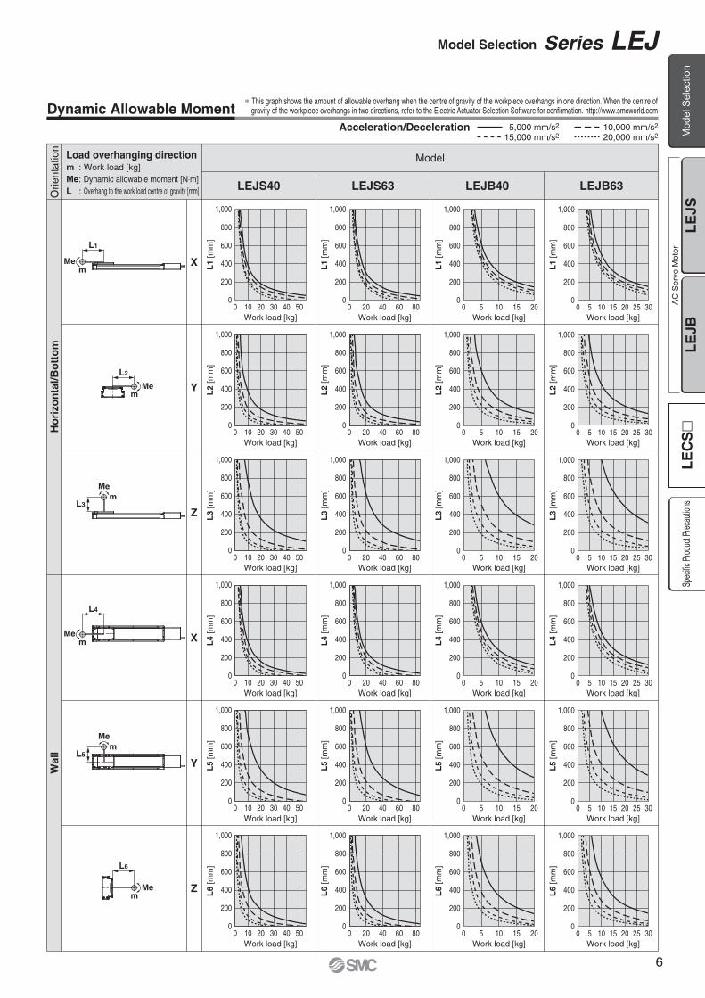
Dynamic Allowable Moment
Work load [kg]
Work load [kg]
Work load [kg]
Work load [kg]
Work load [kg]
L1
[mm
]
Work load [kg]
Work load [kg]
L1
[mm
]
Work load [kg]L
1 [m
m]
Work load [kg]
L1
[mm
]
L2
[mm
]
Work load [kg]L
2 [m
m]
Work load [kg]
L2
[mm
]
Work load [kg]
L2
[mm
]
L3
[mm
]L
4 [m
m]
L5
[mm
]L
6 [m
m]
Work load [kg]
Work load [kg]
Work load [kg]
Work load [kg]
L3
[mm
]L
4 [m
m]
L5
[mm
]L
6 [m
m]
Work load [kg]
Work load [kg]
Work load [kg]
Work load [kg]
L3
[mm
]L
4 [m
m]
L5
[mm
]L
6 [m
m]
Work load [kg]
Work load [kg]
Work load [kg]
Work load [kg]
L3
[mm
]L
4 [m
m]
L5
[mm
]L
6 [m
m]
Load overhanging directionm : Work load [kg]Me: Dynamic allowable moment [N⋅m]L : Overhang to the work load centre of gravity [mm]
Model
LEJB40LEJS40 LEJS63 LEJB63
Ho
rizo
nta
l/Bo
tto
mO
rient
atio
nW
all
Acceleration/Deceleration 5,000 mm/s2
15,000 mm/s210,000 mm/s2
20,000 mm/s2
∗ This graph shows the amount of allowable overhang when the centre of gravity of the workpiece overhangs in one direction. When the centre ofgravity of the workpiece overhangs in two directions, refer to the Electric Actuator Selection Software for confirmation. http://www.smcworld.com
Model Selection Series LEJ
Mod
el S
elec
tion
LE
JSL
EJB
AC
Ser
vo M
otor
Spec
ific P
rodu
ct Pr
ecau
tions
LE
CS
6
0
200
400
600
800
1,000
0 5 10 15 20
0
200
400
600
800
1,000
0 5 10 15 20
0
200
400
600
800
1,000
0 2 4 6 108
0 2 4 6 1080
200
400
600
800
1,000
mMe
L7
mMe
L8
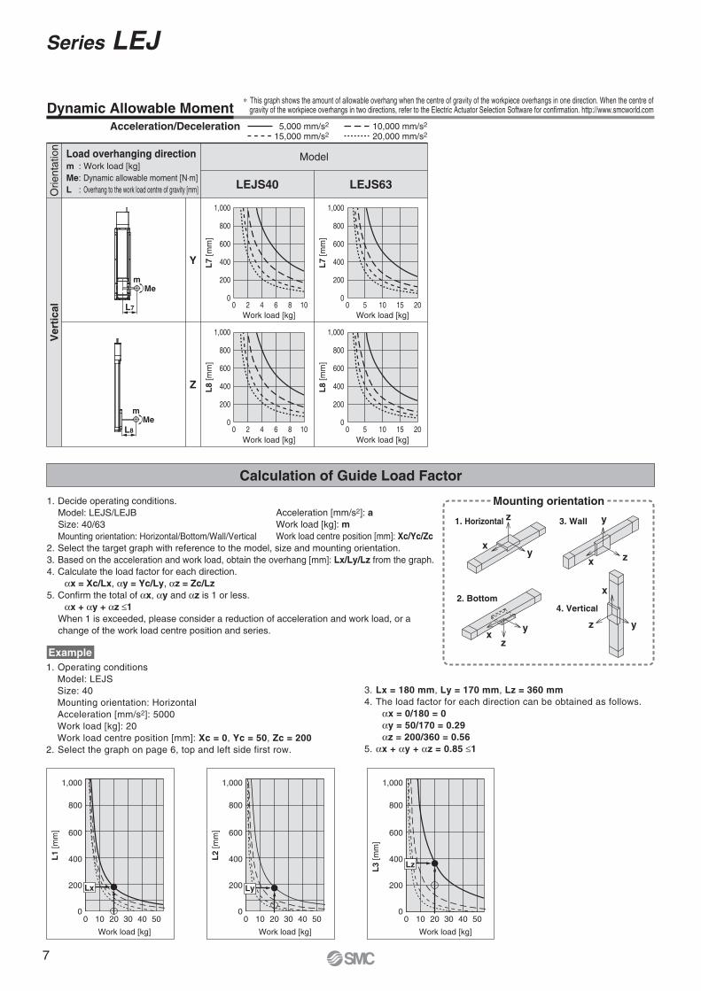
Dynamic Allowable Moment
Calculation of Guide Load Factor
1. Operating conditionsModel: LEJSSize: 40Mounting orientation: HorizontalAcceleration [mm/s2]: 5000Work load [kg]: 20Work load centre position [mm]: Xc = 0, Yc = 50, Zc = 200
2. Select the graph on page 6, top and left side first row.
Work load [kg]
Work load [kg]
L7
[mm
]L
8 [m
m]
Work load [kg]
Work load [kg]
L7
[mm
]L
8 [m
m]
Load overhanging directionm : Work load [kg]Me: Dynamic allowable moment [N⋅m]L : Overhang to the work load centre of gravity [mm]
Model
LEJS40 LEJS63
Ver
tica
lO
rient
atio
n
Example
0
200
400
Lx
600
800
1,000
0 10 20 30 40 50
L1
[mm
]
Work load [kg]
0
200
400
600
800
1,000
0 10 20 30 40 50
L2
[mm
]
Work load [kg]
0
200
400
600
800
1,000
0 10 20 30 40 50
L3
[mm
]
Work load [kg]
Acceleration [mm/s2]: aWork load [kg]: mWork load centre position [mm]: Xc/Yc/Zc
Ly
Lz
xy
z
x z
y
x
z yx
yz
Mounting orientation
1. Horizontal 3. Wall
2. Bottom4. Vertical
∗ This graph shows the amount of allowable overhang when the centre of gravity of the workpiece overhangs in one direction. When the centre of gravity of the workpiece overhangs in two directions, refer to the Electric Actuator Selection Software for confirmation. http://www.smcworld.com
Acceleration/Deceleration 5,000 mm/s2
15,000 mm/s210,000 mm/s2
20,000 mm/s2
1. Decide operating conditions.Model: LEJS/LEJBSize: 40/63Mounting orientation: Horizontal/Bottom/Wall/Vertical
2. Select the target graph with reference to the model, size and mounting orientation.3. Based on the acceleration and work load, obtain the overhang [mm]: Lx/Ly/Lz from the graph.4. Calculate the load factor for each direction.
αx = Xc/Lx, αy = Yc/Ly, αz = Zc/Lz5. Confirm the total of αx, αy and αz is 1 or less.
αx + αy + αz ≤1When 1 is exceeded, please consider a reduction of acceleration and work load, or a change of the work load centre position and series.
3. Lx = 180 mm, Ly = 170 mm, Lz = 360 mm4. The load factor for each direction can be obtained as follows.
αx = 0/180 = 0αy = 50/170 = 0.29αz = 200/360 = 0.56
5. αx + αy + αz = 0.85 ≤1
Series LEJ
7

A side
C side
B side
D side
W
L
wq
Table Accuracy (Reference Value)
Table Displacement (Reference Value)
0.02
0.01
00 100 200 300 400 500
Dis
plac
emen
t [m
m]
Load W [N]
Note) Traveling parallelism does not include the mounting surface accuracy.
Note) This displacement is measured when a 15 mm aluminium plate is mounted and fixed on the table. (Table clearance is included.)
LEJ�40(L = 52.5 mm)
LEJ�63(L = 64.5 mm)
LEJ�40
LEJ�63
Model
0.05
0.05
0.03
0.03
Traveling parallelism [mm] (Every 300 mm)
q C side traveling parallelism to A side
w D side traveling parallelism to B side
Model Selection Series LEJ
Mod
el S
elec
tion
LE
JSL
EJB
AC
Ser
vo M
otor
Spec
ific P
rodu
ct Pr
ecau
tions
LE
CS
8

Compatible Drivers
Driver type
LECSAUp to 7
�—
USB communication
LECSB—�—
USB communication, RS422 communication
100 to 120 VAC (50/60 Hz)200 to 230 VAC (50/60 Hz)
Pulse input type/Positioning type
Pulse input type
LECSCUp to 255
—CC-Link
USB communication, RS422 communication
CC-Link direct input type
LECSS——
SSCNET III
USB communication
SSCNET III type
Series
Number of point tables
Pulse input
Applicable network
Control encoder
Communication
Power supply voltage [V]
Reference page
For auto switches, refer to pages 19 and 20.
Incremental17-bit encoder
Absolute18-bit encoder
Absolute18-bit encoder
Absolute18-bit encoder
Page 25
How to Order
LEJS 40 500A
4063 A
B
LEJS40168
LEJS632010
Symbol
Applicable Stroke Table∗4 �Standard �Produced upon receipt of order
LEJS40LEJS63
�
—
Stroke[mm]Model
200
�
�
�
�
400300
�
�
500
�
�
600
�
�
700 800
�
�
�
�
900
�
�
1000
�
�
—�
1200 1500
—B
Without optionWith lock
1 2 3 4 5 6 7 8 9
∗4: Consult with SMC as all non-standard and non-made-to-order strokes are produced as special orders.
∗1: For motor type S2 and S6, the compatible driver part number suffixes are S1 and S5 respectively.
∗2: For details of the driver, refer to page 26.
∗3: Refer to the table below for details.
1 Size 3 Lead [mm]
5 Motor option
200to
1500
4 Stroke [mm]∗3
—25A
Without cable2 m5 m
10 m
—SR
Without cableStandard cable
Robotic cable (Flexible cable)
∗6: The motor and encoder cables are included. (The lock cable is included when the motor with lock option is selected.)
∗7: Standard cable entry direction is “(A) Axis side”. (Refer to page 36 for details.)
6 Cable type∗5, ∗6, ∗7 7 Cable length [m]∗5, ∗8
S2
S2
S3
100
200
40
63
S6
S7
100
200
40
63
Symbol TypeActuator
sizeOutput
[W]AC servo motor
(Incremental encoder)
AC servo motor(Incremental encoder)
AC servo motor(Absolute encoder)
AC servo motor(Absolute encoder)
2 Motor type∗1
LECSA�-S1
LECSA�-S3
LECSB�-S5LECSC�-S5LECSS�-S5LECSB�-S7LECSC�-S7LECSS�-S7
Compatibledrivers∗2
—H
Without connectorWith connector—
A1A2B1B2C1C2S1S2
8 Driver type∗5 9 I/O connector
Without driverLECSA1-S�LECSA2-S�LECSB1-S�LECSB2-S�LECSC1-S�LECSC2-S�LECSS1-S�LECSS2-S�
—100 to 120200 to 230100 to 120200 to 230100 to 120200 to 230100 to 120200 to 230
Power supply voltage (V)Compatible drivers
∗5: When the driver type is selected, the cable is included. Select cable type and cable length.Example)S2S2: Standard cable (2 m) + Driver (LECSS2)S2 : Standard cable (2 m)— : Without cable and driver
∗8: The length of the motor, encoder and lock cables are the same.
Electric Actuator/High Rigidity Slider TypeBall Screw Drive
Series LEJSAC Servo Motor
RoHS
9

Specifications
Weight
Note 1) Consult with SMC as all non-standard and non-made-to-order strokes are produced as special orders.Note 2) Check “Speed–Work Load Graph (Guide)” on page 2.Note 3) The allowable speed changes according to the stroke.Note 4) Conforming to JIS B 6191-1999Note 5) Impact resistance: No malfunction occurred when the actuator was tested with a drop tester in both an axial direction and a perpendicular direction
to the lead screw. (Test was performed with the actuator in the initial state.)Vibration resistance: No malfunction occurred in a test ranging between 45 to 2000 Hz. Test was performed in both an axial direction and a perpendicular direction to the lead screw. (Test was performed with the actuator in the initial state.)
Note 6) The power consumption (including the driver) is for when the actuator is operating.Note 7) The standby power consumption when operating (including the driver) is for when the actuator is stopped in the set position during the operation.Note 8) The maximum instantaneous power consumption (including the driver) is for when the actuator is operating.Note 9) Only when motor option “With lock” is selected.Note 10) For an actuator with lock, add the power consumption for the lock.
200, 300, (400), 500, 600, (700), 800(900), (1000), (1200)
100/�40 200/�60
30
5
1200
1050
780
600
480
390
320
270
—
—
—
16 8 20 10
20000 (Refer to pages 4 to 7 for limit according to work load and duty ratio.)
±0.02
50/20
Ball screw
Linear guide
20
5 to 40
90 or less (No condensation)
May be required depending on speed and work load. (Refer to page 36.)
AC servo motor (100/200 VAC)
Non-magnetizing lock
24 VDC
55
10
600
520
390
300
240
190
160
130
—
—
—
LEJS40/63 AC Servo Motor Model LEJS40S2
637
Act
uat
or
spec
ific
atio
ns
Ele
ctri
c sp
ecif
icat
ion
sLo
ck u
nit
spec
ifica
tions
Stroke [mm] Note 1)
Max. acceleration/deceleration [mm/s2]
Positioning repeatability [mm] Note 4)
Lead [mm]
Impact/Vibration resistance [m/s2] Note 5)
Actuation type
Guide type
Allowable external force [N]
Operating temperature range [°C]
Operating humidity range [%RH]
Regeneration option
Motor output [W]/Size [mm]
Motor type
Encoder
Power consumption [W] Note 6)
Standby power consumptionwhen operating [W] Note 7)
Max. instantaneous power consumption [W] Note 8)
Type Note 9)
Holding force [N]
Power consumption at 20°C [W] Note 10)
Rated voltage [V]
101 203 330 660
6.3
65
165
2
10
445
80
235
2
12
725
7.9
300, (400), 500, 600, (700), 800, (900)1000, (1200), (1500)
45
10
1200
1200
1200
930
740
600
500
420
360
310
270
85
20
600
600
600
460
370
300
250
210
180
150
130
LEJS63S
Horizontal
Vertical
Up to 500
501 to 600
601 to 700
701 to 800
801 to 900
901 to 1000
1001 to 1100
1101 to 1200
1201 to 1300
1301 to 1400
1401 to 1500
0–10%
Work load [kg] Note 2)
Speed Note 3)
[mm/s]Strokerange
Motor type S2, S3: Incremental 17-bit encoder (Resolution: 131072 p/rev)Motor type S6, S7: Absolute 18-bit encoder (Resolution: 262144 p/rev)
Model
Stroke [mm]
Product weight [kg]
Additional weight with lock [kg]
200
5.6
600
8.7
500
7.9
300
6.4
LEJS40800
10.2
(1000)
11.7
(900)
11.0
(700)
9.4
(400)
7.1
Model
Stroke [mm]
Product weight [kg]
Additional weight with lock [kg]
300
11.4
800
17.7
600
15.2
500
13.9
LEJS631000
20.1
(1200)
22.6
(900)
18.9
(700)
16.4
(400)
12.7
(1200)
13.3
(1500)
26.4
0.2 (Incremental encoder)/0.3 (Absolute encoder)
0.4 (Incremental encoder)/0.7 (Absolute encoder)
Horizontal
Vertical
Horizontal
Vertical
Series LEJSElectric Actuator/High Rigidity Slider TypeBall Screw Drive
Mod
el S
elec
tion
LE
JSL
EJB
AC
Ser
vo M
otor
Spec
ific P
rodu
ct Pr
ecau
tions
LE
CS
10

@3
e u
@0 @1@2w !4 !2 !0!1 !3 !7
t!9 q r !5 y i!8 o !6
No. Description Material Note
1
2
3
4
5
6
7
8
9
10
11
12
Body
Ball screw assembly
Linear guide assembly
Table
Housing A
Housing B
Seal magnet
Motor cover
End cover A
Roller shaft
Roller
Bearing stopper
Aluminium alloy
—
—
Aluminium alloy
Aluminium alloy
Aluminium alloy
—
Aluminium alloy
Aluminium alloy
Stainless steel
Synthetic resin
Carbon steel
Anodised
Anodised
Coating
Coating
Anodised
Anodised
No. Description Material Note
13
14
15
16
17
18
19
20
21
22
23
Coupling
Table cap
Seal band stopper
Blanking plate
Motor
Grommet
Dust seal band
Bearing
Bearing
Nut fixing pin
Magnet
—
Synthetic resin
Synthetic resin
Aluminium alloy
—
NBR
Stainless steel
—
—
Carbon steel
—
Anodised
Component Parts
Construction
Series LEJS
11

Motor option: B/With lock
+0.030 0ø6H9 ( ) depth 4+
0.03
0 0
6H9
(
)
dep
th 4
64
6 +0.030 05H9 ( ) depth 6
+0.030 0ø5H9 ( ) depth 6
58
50.5
36.5
130
100
56M4 x 0.7 depth 8(F.G. terminal)
18
Body mountingreference plane
(128
)
(160)
110
84
4 x M6 x 1 depth 10
94
(3.1)
100
105
35
25.5
Encoder cable(ø7)
Motor cable(ø6)
45
37
(4)
Stroke
A (Table traveling distance) Note 1)
L167 (B: With lock/207)
2±1
(60)(58)
Encoder Z phase detecting position Note 2)
Encoder cable(ø7)
Lock cable(ø4.5)
Motor cable(ø6)
356.
7
25.5
E C x 200 (=D) 20
200
114
B 30
n x ø5.511
50.8
Dimensions: Ball Screw Drive
LEJS40
Note 1) Distance within which the table can move when it returns to origin. Make sure a workpiece mounted on the table does not interfere with the workpieces and facilities around the table.
Note 2) The Z phase first detecting position from the stroke end of the motor side.Note 3) Auto switch magnet is located in the table centre.
LEJS40S��-200�-����LEJS40S��-300�-����LEJS40S��-400�-����LEJS40S��-500�-����LEJS40S��-600�-����LEJS40S��-700�-����LEJS40S��-800�-����LEJS40S��-900�-����LEJS40S��-1000�-����LEJS40S��-1200�-����
ModelWithout lock With lock
L
523.5
623.5
723.5
823.5
923.5
1023.5
1123.5
1223.5
1323.5
1523.5
563.5
663.5
763.5
863.5
963.5
1063.5
1163.5
1263.5
1363.5
1563.5
B
6
6
8
8
10
10
12
12
14
16
260
360
460
560
660
760
860
960
1060
1260
A
206
306
406
506
606
706
806
906
1006
1206
n
1
1
2
2
3
3
4
4
5
6
C
200
200
400
400
600
600
800
800
1000
1200
D
80
180
80
180
80
180
80
180
80
80
E
[mm]
Series LEJSElectric Actuator/High Rigidity Slider TypeBall Screw Drive
Mod
el S
elec
tion
LE
JSL
EJB
AC
Ser
vo M
otor
Spec
ific P
rodu
ct Pr
ecau
tions
LE
CS
12

Dimensions: Ball Screw Drive
LEJS63
LEJS63S��-300�-����LEJS63S��-400�-����LEJS63S��-500�-����LEJS63S��-600�-����LEJS63S��-700�-����LEJS63S��-800�-����LEJS63S��-900�-����LEJS63S��-1000�-����LEJS63S��-1200�-����LEJS63S��-1500�-����
ModelWithout lock With lock
L
696.5
796.5
896.5
996.5
1096.5
1196.5
1296.5
1396.5
1596.5
1896.5
656.5
756.5
856.5
956.5
1056.5
1156.5
1256.5
1356.5
1556.5
1856.5
C
1
2
2
3
3
4
4
5
6
7
B
370
470
570
670
770
870
970
1070
1270
1570
A
306
406
506
606
706
806
906
1006
1206
1506
6
8
8
10
10
12
12
14
16
18
n
200
400
400
600
600
800
800
1000
1200
1400
D
180
80
180
80
180
80
180
80
80
180
E
[mm]
Note 1) Distance within which the table can move when it returns to origin. Make sure a workpiece mounted on the table does not interfere with the workpieces and facilities around the table.
Note 2) The Z phase first detecting position from the stroke end of the motor side.Note 3) Auto switch magnet is located in the table centre.
Motor option: B/With lock
Motor cable(ø6)
79
+0.036 0ø8H9 ( ) depth 6+
0.03
6 0
8H9
(
)
dep
th 6
+0.030 06H9 ( ) depth 7
7
129
124
(3.1)
114
+0.030 0ø6H9 ( ) depth 7
(158
)
M4 x 0.7 depth 8(F.G. terminal)25
68
160
124
73
63.5
49.5
Body mounting reference plane
4 x M8 x 1.25 depth 12
(172)
12290
C x 200 (=D)
200
25
140
n x ø6.8
B
13
30
47
E
35
47
Encoder cable(ø7)
Encoder cable(ø7)
35
6.7
(66)
(64)
58
39
(4)
Stroke
A (Table traveling distance) Note 1)
L
70
186 (B: With lock/226)
2±1
Encoder Z phase detecting position Note 2)
Lock cable(ø4.5)
Motor cable(ø6)
Series LEJS
13

For auto switches, refer to pages 19 and 20.Compatible Drivers
Driver type
LECSAUp to 7
�
—
USB communication
LECSB—�
—
USB communication, RS422 communication
100 to 120 VAC (50/60 Hz)200 to 230 VAC (50/60 Hz)
Pulse input type/Positioning type
Pulse input type
LECSCUp to 255
—CC-Link
USB communication, RS422 communication
CC-Link directinput type
LECSS——
SSCNET III
USB communication
SSCNET III type
Series
Number of point tables
Pulse input
Applicable network
Control encoder
Communication
Power supply voltage [V]
Reference page
Incremental17-bit encoder
Absolute18-bit encoder
Absolute18-bit encoder
Absolute18-bit encoder
Page 25
How to Order
LEJB 40 500T1 2 3 4 5 6 7 8 9
S2
4063 T
LEJB4027
LEJB6342
Symbol
Applicable Stroke Table∗3 �Standard �Produced upon receipt of order
LEJB40LEJB63
�
—�
�
�
�
�
�
�
�
�
�
�
�
�
�
�
�
�
�
�
�
�
�
—�
Stroke[mm]Model
200 300 400 500 700600 800 900 1000 1200 1500 2000 3000
—B
Without optionWith lock
∗3: Consult with SMC as all non-standard and non-made-to-order strokes are produced as special orders.
1 Size 3 Lead [mm]
5 Motor option
200to
3000
4 Stroke [mm]∗2
—25A
Without cable2 m5 m
10 m
—SR
Without cableStandard cable
Robotic cable (Flexible cable)
∗5: The motor and encoder cables are included. (The lock cable is included when the motor with lock option is selected.)
∗6: Standard cable entry direction is “(A) Axis side”. (Refer to page 36 for details.)
∗7: The length of the motor, encoder and lock cables are the same.
6 Cable type∗4, ∗5, ∗6 7 Cable length [m]∗4, ∗7
—H
Without connectorWith connector—
A1A2B1B2C1C2S1S2
8 Driver type∗4 9 I/O connector
Without driverLECSA1LECSA2LECSB1LECSB2LECSC1LECSC2LECSS1LECSS2
—100 to 120200 to 230100 to 120200 to 230100 to 120200 to 230100 to 120200 to 230
Power supply voltage [V]Compatible drivers
∗1: For motor type S2 and S6, the compatible driver part number suffixes are S1 and S5 respectively.
S2
S3
100
200
40
63
S6
S7
100
200
40
63
Symbol TypeActuator
sizeOutput
[W]AC servo motor
(Incremental encoder)
AC servo motor(Incremental encoder)
AC servo motor(Absolute encoder)
AC servo motor(Absolute encoder)
2 Motor type∗1
LECSA�-S1
LECSA�-S3
LECSB�-S5LECSC�-S5LECSS�-S5LECSB�-S7LECSC�-S7LECSS�-S7
Compatibledrivers
∗2: Refer to the table below for details.
∗4: When the driver type is selected, the cable is included. Select cable type and cable length.Example)S2S2: Standard cable (2 m) + Driver (LECSS2)S2 : Standard cable (2 m)— : Without cable and driver
Electric Actuator/High Rigidity Slider TypeBelt Drive
Series LEJBAC Servo Motor
RoHS Mod
el S
elec
tion
LE
JSL
EJB
AC
Ser
vo M
otor
Spec
ific P
rodu
ct Pr
ecau
tions
LE
CS
14

Specifications
Weight
Note 1) Consult with SMC as all non-standard and non-made-to-order strokes are produced as special orders.Note 2) Check “Speed–Work Load Graph (Guide)” on page 2.Note 3) Conforming to JIS B 6191-1999Note 4) Impact resistance: No malfunction occurred when the actuator was tested with a drop tester in both an axial direction and a perpendicular direction
to the lead screw. (Test was performed with the actuator in the initial state.)Vibration resistance: No malfunction occurred in a test ranging between 45 to 2000 Hz. Test was performed in both an axial direction and a perpendicular direction to the lead screw. (Test was performed with the actuator in the initial state.)
Note 5) The power consumption (including the driver) is for when the actuator is operating.Note 6) The standby power consumption when operating (including the driver) is for when the actuator is stopped in the set position during the operation.Note 7) The maximum instantaneous power consumption (including the driver) is for when the actuator is operating.Note 8) Only when motor option “With lock” is selected.Note 9) For an actuator with lock, add the power consumption for the lock.
(200), 300, (400), 500, (600), (700), 800(900), 1000, (1200), (1500), (2000)
100/�40 200/�60
20 (If the stroke exceeds 1000 mm: 10)
2000
27 42
20000 (Refer to pages 4 to 7 for limit according to work load and duty ratio.)
±0.04
50/20
Belt
Linear guide
20
5 to 40
90 or less (No condensation)
May be required depending on speed and work load. (Refer to page 36.)
AC servo motor (100/200 VAC)
Non-magnetizing lock
24 VDC 0–10%
LEJB40/63 AC Servo MotorModel LEJB40S2
637
Act
uat
or
spec
ific
atio
ns
Ele
ctri
c sp
ecif
icat
ion
sLo
ck u
nit
spec
ifica
tions
Stroke [mm] Note 1)
Work load [kg]
Speed [mm/s] Note 2)
Max. acceleration/deceleration [mm/s2]
Positioning repeatability [mm] Note 3)
Lead [mm]
Impact/Vibration resistance [m/s2] Note 4)
Actuation type
Guide type
Allowable external force [N]
Operating temperature range [°C]
Operating humidity range [%RH]
Regeneration option
Motor output [W]/Size [mm]
Motor type
Encoder
Power consumption [W] Note 5)
Standby power consumptionwhen operating [W] Note 6)
Max. instantaneous power consumption [W] Note 7)
Type Note 8)
Holding force [N]
Power consumption at 20°C [W] Note 9)
Rated voltage [V]
65
—
2
—
445
60
6.3
190
—
2
—
725
189
7.9
(300), (400), 500, (600), (700), 800(900), 1000, 1200, (1500), (2000), (3000)
30
3000
LEJB63S
Horizontal
Motor type S2, S3: Incremental 17-bit encoder (Resolution: 131072 p/rev)Motor type S6, S7: Absolute 18-bit encoder (Resolution: 262144 p/rev)
Model
Stroke [mm]
Product weight [kg]
Additional weight with lock [kg]
(200)
5.7
(700)
9.1
(600)
8.4
(400)
7.1
500
7.7
300
6.4
LEJB40800
9.8
0.2 (Incremental encoder)/0.3 (Absolute encoder)
1000
11.2
Model
Stroke [mm]
Product weight [kg]
Additional weight with lock [kg]
(300)
11.5
(400)
12.7
800
17.4
(600)
15.0
500
13.8
LEJB631000
19.70.4 (Incremental encoder)/0.7 (Absolute encoder)
1200
22.1
(1200)
12.6
(900)
10.5
(1500)
14.7
(2000)
18.1
(1500)
25.7
(900)
18.6
(700)
16.2
(2000)
31.6
(3000)
43.4
Horizontal
Vertical
Horizontal
Vertical
Series LEJB
15

Motor details
#8
ot
u
!6 !5 w r e #7!3!4 !7 #1 !8 #0 @5
@1 @8!9 #6 #5 #2
#4 q y i !2 !1 !0#3 @3 @6 @7 @9@4
@0 @2
No. Description Material Note
1
2
3
4
5
6
7
8
9
10
11
12
13
14
15
16
17
18
19
Body
Belt
Belt holder
Belt stopper
Linear guide assembly
Table
Housing A
Housing B
Seal magnet
Motor cover
End cover A
End cover B
Roller shaft
Roller
Pulley holder
Drive pulley
Speed reduction pulley
Motor pulley
Spacer
Aluminium alloy
—
Carbon steel
Aluminium alloy
—
Aluminium alloy
Aluminium alloy
Aluminium alloy
—
Aluminium alloy
Aluminium alloy
Aluminium alloy
Stainless steel
Synthetic resin
Aluminium alloy
Aluminium alloy
Aluminium alloy
Aluminium alloy
Aluminium alloy
Anodised
Anodised
Coating
Coating
Anodised
Anodised
Anodised
No. Description Material Note
20
21
22
23
24
25
26
27
28
29
30
31
32
33
34
35
36
37
38
Pulley shaft A
Pulley shaft B
Table cap
Seal band stopper
Blanking plate
Motor mount plate
Pulley block
Pulley cover
Belt stopper
Side plate
Motor plate
Belt
Motor
Grommet
Dust seal band
Bearing
Bearing
Stopper pin
Magnet
Stainless steel
Stainless steel
Synthetic resin
Synthetic resin
Aluminium alloy
Carbon steel
Aluminium alloy
Aluminium alloy
Aluminium alloy
Aluminium alloy
Carbon steel
—
—
NBR
Stainless steel
—
—
Stainless steel
—
Anodised
Anodised
Anodised
Anodised
Component Parts
Construction
Series LEJBElectric Actuator/High Rigidity Slider TypeBelt Drive
Mod
el S
elec
tion
LE
JSL
EJB
AC
Ser
vo M
otor
Spec
ific P
rodu
ct Pr
ecau
tions
LE
CS
16

Motor option: B/With lock
+0.030 0ø6H9 ( ) depth 4+
0.03
0 0
6H9
(
)
dep
th 4
64
(128
) +0.030 05H9 ( ) depth 6
+0.030 0ø5H9 ( ) depth 6
94
58
50.5
36.5
130
100
56M4 x 0.7 depth 8(F.G. terminal)
18
Body mounting reference plane
84
110
(160)4 x M6 x 1 depth 10
10526
44
3.5
121
(3.1
)(3
.1)
6
Encoder cable(ø7)
Motor cable(ø6)
E200
20C x 200 (=D)
114
11 n x ø5.5
B 30
45
37
(4)
Stroke
A (Table traveling distance) Note 1)
L
2±1
(60)
(58)
Encoder Z phase detecting position Note 2)
185.5
50.893
170
3.5
26
Encoder cable(ø7)
Lock cable(ø4.5)
Motor cable(ø6)
Dimensions: Belt Drive
LEJB40
Note 1) Distance within which the table can move when it returns to origin. Make sure a workpiece mounted on the table does not interfere with the workpieces and facilities around the table.
Note 2) The Z phase first detecting position from the stroke end of the motor side.Note 3) Auto switch magnet is located in the table centre.
LEJB40S��-200�-����LEJB40S��-300�-����LEJB40S��-400�-����LEJB40S��-500�-����LEJB40S��-600�-����LEJB40S��-700�-����LEJB40S��-800�-����LEJB40S��-900�-����LEJB40S��-1000�-����LEJB40S��-1200�-����LEJB40S��-1500�-����LEJB40S��-2000�-����
Model L 206
306
406
506
606
706
806
906
1006
1206
1506
2006
542
642
742
842
942
1042
1142
1242
1342
1542
1842
2342
n 6
6
8
8
10
10
12
12
14
16
18
24
BA 260
360
460
560
660
760
860
960
1060
1260
1560
2060
1
1
2
2
3
3
4
4
5
6
7
10
C 200
200
400
400
600
600
800
800
1000
1200
1400
2000
D 80
180
80
180
80
180
80
180
80
80
180
80
E[mm]
Series LEJB
17

Dimensions: Belt Drive
LEJB63
LEJB63S��-300�-����LEJB63S��-400�-����LEJB63S��-500�-����LEJB63S��-600�-����LEJB63S��-700�-����LEJB63S��-800�-����LEJB63S��-900�-����LEJB63S��-1000�-����LEJB63S��-1200�-����LEJB63S��-1500�-����LEJB63S��-2000�-����LEJB63S��-3000�-����
Model L 306
406
506
606
706
806
906
1006
1206
1506
2006
3006
704
804
904
1004
1104
1204
1304
1404
1604
1904
2404
3404
n 6
8
8
10
10
12
12
14
16
18
24
34
BA 370
470
570
670
770
870
970
1070
1270
1570
2070
3070
1
2
2
3
3
4
4
5
6
7
10
15
C 200
400
400
600
600
800
800
1000
1200
1400
2000
3000
D180
80
180
80
180
80
180
80
80
180
80
80
E[mm]
Note 1) Distance within which the table can move when it returns to origin. Make sure a workpiece mounted on the table does not interfere with the workpieces and facilities around the table.
Note 2) The Z phase first detecting position from the stroke end of the motor side.Note 3) Auto switch magnet is located in the table centre.
Motor option: B/With lock
(158
) +0.030 06H9 ( ) depth 7
+0.030 0ø6H9 ( ) depth 7
114
73
63.5
49.5
160
124
6825
M4 x 0.7 depth 8(F.G. terminal)
Body mounting reference plane (172)
12290
4 x M8 x 1.25 depth 12
129
(3.1
)413
7
45
35
Motor cable(ø6)
Encoder cable(ø7)
(3.1
)
7
58
39
(4)
Stroke
A (Table traveling distance) Note 1)
L233.5
Encoder Z phase detecting position Note 2)
2±1
(66)
(64)
70
177
85
4
Motor cable(ø6)
35
Encoder cable(ø7)
Lock cable(ø4.5)
+0.036 0ø8H9 ( ) depth 6+
0.03
6 0
8H9
(
)
dep
th 6
140
B
n x ø6.813
30
E C x 200 (=D)
200
25
79
Series LEJBElectric Actuator/High Rigidity Slider TypeBelt Drive
Mod
el S
elec
tion
LE
JSL
EJB
AC
Ser
vo M
otor
Spec
ific P
rodu
ct Pr
ecau
tions
LE
CS
18

DC (+)Brown
OUTBlack
DC (–)Blue
DC (+)Brown
OUTBlack
DC (–)Blue
Solid State Auto SwitchDirect Mounting StyleD-M9N(V)/D-M9P(V)/D-M9B(V)
Auto Switch Internal CircuitD-M9N/M9NV
D-M9B/M9BV
D-M9P/M9PV
Auto Switch Specifications
Weight
Auto switch model
0.5
1
3
5
D-M9N(V)8
14
41
68
D-M9P(V)8
14
41
68
D-M9B(V)7
13
38
63
[g]
Lead wire length[m]
Grommet PLC: Programmable Logic Controller
D-M9NVD-M9N D-M9B D-M9BV
2-wire
—
24 VDC relay, PLC
—
—
24 VDC (10 to 28 VDC)
2.5 to 40 mA
4 V or less
0.8 mA or less
D-M9PVD-M9P
Red LED lights up when turned ON.
CE marking, RoHS
Auto switch model
Electrical entry
Wiring type
Output type
Applicable load
Power supply voltage
Current consumption
Load voltage
Load current
Internal voltage drop
Leakage current
Indicator light
Standards
3-wire
IC circuit, Relay, PLC
5, 12, 24 VDC (4.5 to 28 V)
10 mA or less
40 mA or less
0.8 V or less at 10 mA (2 V or less at 40 mA)
100 μA or less at 24 VDC
In-line Perpendicular In-line Perpendicular In-line Perpendicular
NPN PNP
28 VDC or less —
OUT (+)Brown
OUT (–)Blue
D-M9�, D-M9�V (With indicator light)
� Lead wires — Oilproof flexible heavy-duty vinyl cord: ø2.7 x 3.2 ellipse, 0.15 mm2, 2 cores (D-M9B(V)), 3 cores (D-M9N(V)/D-M9P(V))
Note) Refer to Best Pneumatics No. 2 for solid state auto switch common specifications.
How to Order
� 2-wire load current is reduced (2.5 to 40 mA).
� Flexibility is 1.5 times greater than the conventional model (SMC comparison).
� Using flexible cable as standard.
PrecautionsCaution
Dimensions [mm]
Fix the auto switch with the existing screw installed on the auto switch body. The auto switch may be damaged if a screw other than the one supplied is used.
Series
NPB
3-wire NPN3-wire PNP
2-wire
Wiring/Output type
D-M9 N
—V
In-linePerpendicular
Electrical entry
—MLZ
0.5 m1 m3 m5 m
Lead wire length
Refer to SMC website for details about products conforming to the international standards.
Mai
n ci
rcui
tof
sw
itch
Mai
n ci
rcui
tof
sw
itch
Mai
n ci
rcui
tof
sw
itch
RoHS
M2.5 x 4 LSlotted set screw
Indicator light
2.722
2.6
4
2.8
3.2
6 Most sensitive position
4
2.6
9.5
M2.5 x 4 LSlotted set screw
Indicator light
Most sensitive position
2
20
6
83.2
2.7
4.6
2.8
4
D-M9�
D-M9�V
19

Auto Switch Specifications
Weight [g]
[mm]Dimensions
Auto switch model
0.5
1
3
5
D-M9NW(V)8
14
41
68
D-M9PW(V)8
14
41
68
D-M9BW(V)7
13
38
63
Lead wire length[m]
Grommet PLC: Programmable Logic Controller
D-M9NWVD-M9NW D-M9BW D-M9BWV
2-wire
—
24 VDC relay, PLC
—
—
24 VDC (10 to 28 VDC)
2.5 to 40 mA
4 V or less
0.8 mA or less
D-M9PWVD-M9PW
Operating range .......... Red LED lights up.Optimum operating range .......... Green LED lights up.
3-wire
IC circuit, Relay, PLC
5, 12, 24 VDC (4.5 to 28 V)
10 mA or less
40 mA or less
0.8 V or less at 10 mA (2 V or less at 40 mA)
100 μA or less at 24 VDC
CE marking, RoHS
In-line Perpendicular In-line Perpendicular In-line Perpendicular
NPN PNP
28 VDC or less —
D-M9�W, D-M9�WV (With indicator light)Auto switch model
Electrical entry
Wiring type
Output type
Applicable load
Power supply voltage
Current consumption
Load voltage
Load current
Internal voltage drop
Leakage current
Indicator light
Standards
� Lead wires — Oilproof flexible heavy-duty vinyl cord: ø2.7 x 3.2 ellipse, 0.15 mm2, 2 cores(D-M9BW(V)), 3 cores (D-M9NW(V), D-M9PW(V))
Note) Refer to Best Pneumatics No. 2 for solid state auto switch common specifications.
� 2-wire load current is reduced (2.5 to 40 mA).
� Flexibility is 1.5 times greater than the conventional model (SMC comparison).
� Using flexible cable as standard.� The optimum operating range can be
determined by the colour of the light. (Red → Green ← Red)
D-M9NW/M9NWV
D-M9BW/M9BWV
D-M9PW/M9PWV
OUTBlack
DC (+)Brown
DC (–)Blue
DC (+)Brown
OUTBlack
DC (–)Blue
OUT (+)Brown
OUT (–)Blue
Auto Switch Internal Circuit
2-Colour Indication Solid State Auto Switch Direct Mounting StyleD-M9NW(V)/D-M9PW(V)/D-M9BW(V)
PrecautionsCaution
Fix the auto switch with the existing screw installed on the auto switch body. The auto switch may be damaged if a screw other than the one supplied is used.
How to Order
Series
NPB
3-wire NPN3-wire PNP
2-wire
Wiring/Output type
D-M9 N W V L
—V
In-linePerpendicular
Electrical entry
—MLZ
0.5 m1 m3 m5 m
Lead wire length
Optimum operating range
Operating range OFF
ON
DisplayRed Green Red
Indicator light/Indication method
Refer to SMC website for details about products conforming to the international standards.
Mai
n ci
rcui
tof
sw
itch
Mai
n ci
rcui
tof
sw
itch
Mai
n ci
rcui
tof
sw
itch
RoHS
M2.5 x 4 L
Indicator light
2.722
2.6
4
2.8
3.2
6 Most sensitive position
4
2.6
9.5
M2.5 x 4 L Indicator light
Slotted set screw
2.8
4.6
4
20
28
3.2
6 Most sensitive position
2.7
Slotted set screw
D-M9�W
D-M9mWV
Mod
el S
elec
tion
LE
JSL
EJB
AC
Ser
vo M
otor
LE
CS
Spec
ific P
rodu
ct Pr
ecau
tions
20

Design Handling
Caution Caution
Warning
1. Do not apply a load in excess of the operating limit.Select a suitable actuator by maximum load and allowable moment. If the product is used outside of the operating limit, the eccentric load applied to the guide will be excessive and have adverse effects such as creating play on the guide, degrading accuracy and shortening the life of the product.
2. Do not use the product in applications where excessive external force or impact force is applied to it.The product can be damaged.The components including the motor are manufactured to precise tolerances. So that even a slight deformation may cause a malfunction or seizure.
Selection
1. Do not increase the speed in excess of the operating limit.Select a suitable actuator by the relationship of the allowable work load and speed, and the allowable speed of each stroke. If the product is used outside of the operating limit, it will have adverse effects such as creating noise, degrading accuracy and shortening the life of the product.
2. When the product repeatedly cycles with partial strokes (100 mm or less), lubrication can run out. Operate it at a full stroke at least once a day or every 1000 strokes.
3. When external force is applied to the table, it is necessary to add external force to the work load as the total carried load for the sizing.When a cable duct or flexible moving tube is attached to the actuator, the sliding resistance of the table increases and may lead to operational failure of the product.
1. Do not allow the table to hit the end of stroke.It can cause damage to the actuator.
Handle the actuator with care, especially when it is used in the vertical direction.
2. The actual speed of this actuator is affected by the work load and stroke.Check specifications with reference to the model selection section of the catalogue.
3. Do not apply a load, impact or resistance in addition to the transferred load during return to origin.
4. Do not dent, scratch or cause other damage to the body and table mounting surfaces.It may cause a loss of parallelism in the mounting surfaces, looseness in the guide unit, an increase in sliding resistance or other problems.
5. Do not apply strong impact or an excessive moment while mounting the product or a workpiece.If an external force over the allowable moment is applied, it may cause looseness in the guide unit, an increase in sliding resistance or other problems.
6. Keep the flatness of mounting surface 0.1 mm or less.Insufficient flatness of a workpiece or base mounted on the body of the product may cause play on the guide and increased sliding resistance.In the case of overhang mounting (including cantilever), to avoid deflection of the actuator body, use a support plate or support guide.
7. When mounting the actuator, use all mounting holes.If all mounting holes are not used, it influences the specifications, e.g., the amount of displacement of the table increases.
8. Do not hit the table with the workpiece in the positioning operation and positioning range.
9. Do not apply external force to the dust seal band.Particularly during the transportation.
Series LEJ Electric Actuator/Specific Product Precautions 1Be sure to read before handling. Refer to back cover for Safety Instructions and theOperation Manual for Electric Actuator Precautions.Please download it via our website, http://www.smcworld.com
21
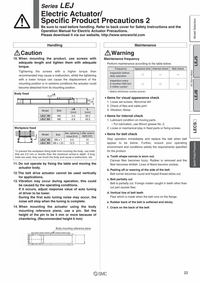
LEJ�40LEJ�63
Model
M6 x 1M8 x 1.25
Bolt
5.212.5
Max. tighteningtorque [N⋅m]
1012
L (Max. screw-indepth) [mm]
To prevent the workpiece fixing bolts from touching the body, use bolts that are 0.5 mm or shorter than the maximum screw-in depth. If long bolts are used, they can touch the body and cause a malfunction, etc.
Workpiece fixed
Body fixed
LEJ�40LEJ�63
Model
M5M6
Bolt
5.56.8
øA[mm]
36.549.5
L[mm]
øAL
L
Handling Maintenance
Caution10. When mounting the product, use screws with
adequate length and tighten them with adequate torque.Tightening the screws with a higher torque than recommended may cause a malfunction, whilst the tightening with a lower torque can cause the displacement of the mounting position or in extreme conditions the actuator could become detached from its mounting position.
11. Do not operate by fixing the table and moving the actuator body.
12. The belt drive actuator cannot be used vertically for applications.
13. Vibration may occur during operation, this could be caused by the operating conditions.If it occurs, adjust response value of auto tuning of driver to be lower.During the first auto tuning noise may occur, the noise will stop when the tuning is complete.
14. When mounting the actuator using the body mounting reference plane, use a pin. Set the height of the pin to be 5 mm or more because of chamfering. (Recommended height 6 mm)
Series LEJ Electric Actuator/Specific Product Precautions 2Be sure to read before handling. Refer to back cover for Safety Instructions and the Operation Manual for Electric Actuator Precautions.Please download it via our website, http://www.smcworld.com
Maintenance frequencyPerform maintenance according to the table below.
• Items for visual appearance check1. Loose set screws, Abnormal dirt2. Check of flaw and cable joint3. Vibration, Noise
• Items for internal check1. Lubricant condition on moving parts.
∗ For lubrication, use lithium grease No. 2.2. Loose or mechanical play in fixed parts or fixing screws.
• Items for belt checkStop operation immediately and replace the belt when belt appear to be below. Further, ensure your operating environment and conditions satisfy the requirements specified for the product.
a. Tooth shape canvas is worn out.Canvas fiber becomes fuzzy. Rubber is removed and the fiber becomes whitish. Lines of fibers become unclear.
b. Peeling off or wearing of the side of the beltBelt corner becomes round and frayed thread sticks out.
c. Belt partially cutBelt is partially cut. Foreign matter caught in teeth other than cut part causes flaw.
d. Vertical line of belt teethFlaw which is made when the belt runs on the flange.
e. Rubber back of the belt is softened and sticky.
f . Crack on the back of the belt
Inspection before daily operation
Inspection every6 months/1000 km/5 million cycles∗
�
�
Appearance check
—
�
Internal checkFrequency
—
�
Belt check
∗ Select whichever comes sooner.
Warning
Body mounting reference plane
Mod
el S
elec
tion
LE
JSL
EJB
AC
Ser
vo M
otor
Spec
ific P
rodu
ct Pr
ecau
tions
LE
CS
22

23

AC Servo Motor DriverSeries LECS�
Pulse input type/Positioning type
Pulse input type
Series LECSAIncremental type
Series LECSBAbsolute type
CC-Link direct input type
Series LECSCAbsolute type
Series LECSSAbsolute type
SSCNET III type
Mod
el S
elec
tion
LE
JSL
EJB
AC
Ser
vo M
otor
LE
CS
Spec
ific P
rodu
ct Pr
ecau
tions
24

Series LECSA (Pulse input type/Positioning type)
Series LECS�
Series LECSB (Pulse input type)
Series LECSC (CC-Link direct input type)
Series LECSS (SSCNET III type)
Incr
emen
tal T
ype
AC Servo Motor DriverA
bso
lute
Typ
ePower supply voltage 100 to 120 VAC
200 to 230 VAC
Motor capacity 100/200 W
Up to 7 positioning points by point table
Input type: Pulse input
Control encoder: Incremental 17-bit encoder (Resolution: 131072 pulse/rev)
Parallel input: 6 inputs output: 4 outputs
Input type: Pulse input
Control encoder: Absolute 18-bit encoder (Resolution: 262144 pulse/rev)
Parallel input: 10 inputs output: 6 outputs
Position data/speed data setting and operation start/stop
Positioning by up to 255 point tables (when 2 stations occupied)
Up to 32 drivers connectable (when 2 stations occupied) with CC-Link communication
Applicable Fieldbus protocol: CC-Link (Ver. 1.10, max. communication speed: 10 Mbps)
Control encoder: Absolute 18-bit encoder (Resolution: 262144 pulse/rev)
Compatible with Mitsubishi Electric,s servo system controller network
Reduced wiring and SSCNET III optical cable for one-touch connection
SSCNET III optical cable provides enhanced noise resistance
Up to 16 drivers connectable with SSCNET III communication
Applicable Fieldbus protocol: SSCNET III (High-speed optical communication, max. bidirectional communication speed: 100 Mbps)
Control encoder: Absolute 18-bit encoder (Resolution: 262144 pulse/rev)
25

How to Order
Series LECSB/LECSC/LECSS Absolute TypeSeries LECSA (Pulse Input Type/Positioning Type)
Incremental TypeAC Servo Motor Driver
Dimensions
LECSA�
LECSB�
LECS 1A S1Driver type
Compatible motor type
Power supply voltage
S1 S3S5S7
TypeAC servo motor (S2)AC servo motor (S3)AC servo motor (S6)AC servo motor (S7)
Capacity100 W200 W100 W200 W
Encoder
Incremental
Absolute
Symbol
A
B
C
S
Pulse input type(For absolute encoder)
CC-Link direct input type(For absolute encoder)
SSCNET III type(For absolute encoder)
Pulse input type/Positioning type(For incremental encoder)
12
100 to 120 VAC, 50/60 Hz200 to 230 VAC, 50/60 Hz
LECSA LECSB LECSC LECSS
Connector name DescriptionCN1CN2CN3CNP1CNP2
I/O signal connectorEncoder connectorUSB communication connectorMain circuit power supply connectorControl circuit power supply connector
Connector name Description
CN1CN2CN3CN4CN5CN6CNP1CNP2CNP3
I/O signal connectorEncoder connectorRS-422 communication connectorBattery connectorUSB communication connectorAnalog monitor connectorMain circuit power supply connectorControl circuit power supply connectorServo motor power connector
(Pulse Input Type) (CC-Link Direct Input Type) (SSCNET III Type)
Driver
6
5.5
5
130
120
40135 2 x ø6 Mounting hole(Bearing surface thickness 5)
∗1 Battery included.
ø6 Mounting hole(Bearing surface thickness 4)
CN3
CNP3
CNP2
CNP1
CN2
CN1
CN3
Battery∗1
CN1
CN2
CN4
CN6CN5
CNP2
CNP1
(14)
156
66
6
161
168
40
135 (For LECSB�-S5, S7) 6
Mod
el S
elec
tion
LE
JSL
EJB
AC
Ser
vo M
otor
LE
CS
Spec
ific P
rodu
ct Pr
ecau
tions
26

Connector name DescriptionCN1CN2CN3CN4CN5CN6CNP1CNP2CNP3
CC-Link connectorEncoder connectorRS-422 communication connectorBattery connectorUSB communication connectorI/O signal connectorMain circuit power supply connectorControl circuit power supply connectorServo motor power connector
Connector name Description
CN1A
CN1B
CN2CN3CN4CN5CNP1CNP2CNP3
Encoder connectorI/O signal connectorBattery connectorUSB communication connectorMain circuit power supply connectorControl circuit power supply connectorServo motor power connector
Front axis connector forSSCNET III optical cable
Rear axis connector forSSCNET III optical cable
6
6
615
6
40
135 (For LECSC�-S5, S7)
∗ Battery included.
2 x ø6(Bearing surface thickness 4)
CN3
CN2
CN1
CN2CN4
Battery∗
Battery∗
CN6
CN1
CN3
CN516
8
6
6
615
6
40
135 (For LECSS�-S5, S7)
∗ Battery included.
2 x ø6(Bearing surface thickness 4)
CNP3
CNP2
CNP1
CN2
CN4
CN1B
CN1A
CN3
CN5
168
Dimensions
LECSC�
LECSS�
Series LECS�
27

ModelCompatible motor capacity [W]
Compatible encoder
Power voltage [V]Allowable voltage fluctuation [V]Rated current [A]Control power supply voltage [V]Allowable voltage fluctuation [V]Rated current [A]
In-position range setting [pulse]Error excessiveTorque limitCommunication
Parallel inputParallel outputMax. input pulse frequency [pps]
Operating temperature range [°C]Operating humidity range [%RH]Storage temperature range [°C]Storage humidity range [%RH]Insulation resistance [MΩ]Weight [g]
Function
LECSA1-S1100
3.0
LECSA1-S3200
5.0
Single phase 100 to 120 VAC (50/60 Hz)Single phase 85 to 132 VAC
LECSA2-S1100
1.524 VDC
21.6 to 26.4 VDC0.5
6 inputs4 outputs
1 M (for differential receiver), 200 k (for open collector)0 to ±65535 (Command pulse unit)
±3 rotationsParameter setting
USB communication0 to 55 (No freezing)
90 or less (No condensation)–20 to 65 (No freezing)
90 or less (No condensation)Between the housing and SG: 10 (500 VDC)
600
LECSA2-S3200
2.4
Single phase 200 to 230 VAC (50/60 Hz)Single phase 170 to 253 VAC
Incremental 17-bit encoder(Resolution: 131072 p/rev)
Specifications
Series LECSA
Series LECSBModel LECSB1-S5 LECSB1-S7 LECSB2-S5 LECSB2-S7
Compatible motor capacity [W]
Compatible encoder
Power voltage [V]
Allowable voltage fluctuation [V]
Rated current [A]Control power supply voltage [V]Allowable voltage fluctuation [V]Rated current [A]
In-position range setting [pulse]Error excessiveTorque limitCommunication
Parallel inputParallel outputMax. input pulse frequency [pps]
Operating temperature range [°C]Operating humidity range [%RH]Storage temperature range [°C]Storage humidity range [%RH]Insulation resistance [MΩ]Weight [g]
Main power supply
Function
Control power supply
100 200 100 200
3.0 5.0
Single phase 100 to 120 VAC (50/60 Hz)
Single phase 85 to 132 VAC
0.9
10 inputs6 outputs
1 M (for differential receiver), 200 k (for open collector)0 to ±10000 (Command pulse unit)
±3 rotationsParameter setting or external analog input setting (0 to 10 VDC)
USB communication, RS422 communication∗1
0 to 55 (No freezing)90 or less (No condensation)
–20 to 65 (No freezing)90 or less (No condensation)
Between the housing and SG: 10 (500 VDC)
Single phase 100 to 120 VAC (50/60 Hz) Single phase 85 to 132 VAC
0.4
Single phase 200 to 230 VAC (50/60 Hz) Single phase 170 to 253 VAC
0.2
1.5
800
Three phase 200 to 230 VAC (50/60 Hz)Single phase 200 to 230 VAC (50/60 Hz)
Three phase 170 to 253 VACSingle phase 170 to 253 VAC
Absolute 18-bit encoder(Resolution: 262144 p/rev)
∗1 USB communication and RS422 communication cannot be performed at the same time.
Main power supply
Control power supply
AC Servo Motor Driver Series LECS�
Mod
el S
elec
tion
LE
JSL
EJB
AC
Ser
vo M
otor
LE
CS
Spec
ific P
rodu
ct Pr
ecau
tions
28

Series LECSC
∗1 If the system comprises of both CC-Link Ver. 1.00 and Ver. 1.10 compliant cables, Ver. 1.00 specifications are applied to the cable extensions and the cable length between stations.∗2 USB communication and RS422 communication cannot be performed at the same time.
Specifications
Series LECSS
ModelCompatible motor capacity [W]
Compatible encoder
CommunicationOperating temperature range [°C]Operating humidity range [%RH]Storage temperature range [°C]Storage humidity range [%RH]Insulation resistance [MΩ]Weight [g]
Power voltage [V]
Allowable voltage fluctuation [V]
Rated current [A]
Control power supply voltage [V]
Allowable voltage fluctuation [V]Rated current [A]Applicable Fieldbus protocol (Version)Connection cableRemote station number
Cablelength
Number of connectable drivers
I/O occupation area (Inputs/Outputs)
Remote register input
Point table No. input
Indexer positioning input
LECSC1-S5100
Single phase 85 to 132 VAC
LECSC1-S7200
Single phase 100 to 120 VAC (50/60 Hz)
Single phase 100 to 120 VAC (50/60 Hz)
Single phase 85 to 132 VAC 0.4
Single phase 200 to 230 VAC (50/60 Hz)
Single phase 170 to 253 VAC 0.2
LECSC2-S5100
Three phase 170 to 253 VACSingle phase 170 to 253 VAC
0.9
USB communication, RS422 communication∗2
0 to 55 (No freezing)90 or less (No condensation)
–20 to 65 (No freezing)90 or less (No condensation)
Between the housing and SG: 10 (500 VDC)
CC-Link communication (Ver. 1.10)CC-Link Ver. 1.10 compliant cable (Shielded 3-core twisted pair cable)∗1
1 to 64
0.2 or more
Up to 42 (when 1 station is occupied by 1 driver), Up to 32 (when 2 stations are occupied by1 driver), when there are only remote device stations.
Available with CC-Link communication (2 stations occupied)Available with CC-Link communication, RS422 communicationCC-Link communication (1 station occupied): 31 pointsCC-Link communication (2 stations occupied): 255 pointsRS422 communication: 255 points
Available with CC-Link communicationCC-Link communication (1 station occupied): 31 pointsCC-Link communication (2 stations occupied): 255 points
1 station occupied (Remote I/O 32 points/32 points)/(Remote register 4 words/4 words)2 stations occupied (Remote I/O 64 points/64 points)/(Remote register 8 words/8 words)
3.0 5.0
800
1.5
2.5 M400
16 k1200
625 k900
5 M160
LECSC2-S7200
Three phase 200 to 230 VAC (50/60 Hz)Single phase 200 to 230 VAC (50/60 Hz)
Absolute 18-bit encoder(Resolution: 262144 p/rev)
Control power supply
Command method
Main power supply
Communication speed [bps]Maximum overall cable length [m]Cable length between stations [m]
Communication specifications
ModelCompatible motor capacity [W]
Compatible encoder
Applicable Fieldbus protocolCommunicationOperating temperature range [°C]Operating humidity range [%RH]Storage temperature range [°C]Storage humidity range [%RH]Insulation resistance [MΩ]Weight [g]
Power voltage [V]
Allowable voltage fluctuation [V]
Rated current [A]
Control power supply voltage [V]
Allowable voltage fluctuation [V]Rated current [A]
LECSS1-S5100
Single phase 85 to 132 VAC
LECSS1-S7200
Single phase 100 to 120 VAC (50/60 Hz)
Single phase 100 to 120 VAC (50/60 Hz)
Single phase 200 to 230 VAC (50/60 Hz)
Single phase 85 to 132 VAC 0.4
Single phase 170 to 253 VAC 0.2
LECSS2-S5100
Three phase 170 to 253 VACSingle phase 170 to 253 VAC
0.9
SSCNET III (High-speed optical communication)USB communication0 to 55 (No freezing)
90 or less (No condensation)–20 to 65 (No freezing)
90 or less (No condensation)Between the housing and SG: 10 (500 VDC)
3.0 5.0 1.5
LECSS2-S7200
Three phase 200 to 230 VAC (50/60 Hz)Single phase 200 to 230 VAC (50/60 Hz)
Absolute 18-bit encoder(Resolution: 262144 p/rev)
Control power supply
Main power supply
800
Series LECS�
29
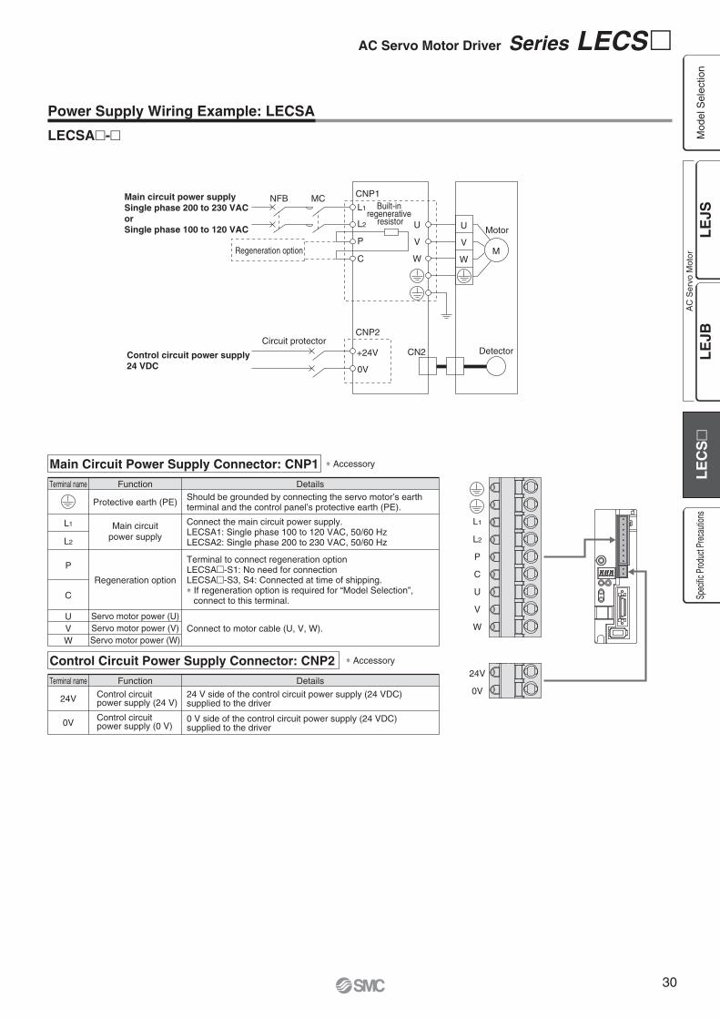
Power Supply Wiring Example: LECSA
LECSA�-�
Terminal name Function Details
L1 L1
L2
P
C
U
V
W
24V
0V
L2
P
C
UVW
Main circuitpower supply
Regeneration option
Servo motor power (U)Servo motor power (V)Servo motor power (W)
Protective earth (PE)
Connect the main circuit power supply.LECSA1: Single phase 100 to 120 VAC, 50/60 HzLECSA2: Single phase 200 to 230 VAC, 50/60 Hz
Terminal to connect regeneration optionLECSA�-S1: No need for connectionLECSA�-S3, S4: Connected at time of shipping.∗ If regeneration option is required for “Model Selection”, connect to this terminal.
Connect to motor cable (U, V, W).
Should be grounded by connecting the servo motor’s earthterminal and the control panel’s protective earth (PE).
Terminal name Function Details
24V
0V
Control circuit power supply (24 V)
Control circuit power supply (0 V)
24 V side of the control circuit power supply (24 VDC) supplied to the driver
0 V side of the control circuit power supply (24 VDC) supplied to the driver
∗ Accessory
∗ Accessory
Main Circuit Power Supply Connector: CNP1
Control Circuit Power Supply Connector: CNP2
Main circuit power supplySingle phase 200 to 230 VACorSingle phase 100 to 120 VAC
Control circuit power supply24 VDC
L1
CNP1NFB MCBuilt-in
regenerative resistor
Regeneration option
CN2
L2
P
U
V
W
U MotorV
WM
C
+24V
CNP2
0V
DetectorCircuit protector
AC Servo Motor Driver Series LECS�
Mod
el S
elec
tion
LE
JSL
EJB
AC
Ser
vo M
otor
LE
CS
Spec
ific P
rodu
ct Pr
ecau
tions
30

Main Circuit Power Supply Connector: CNP1Terminal name Function Details
L1
L2
L3
NP1
P2
Main circuitpower supply
Connect the main circuit power supply.LECSB1/LECSC1/LECSS1: Single phase 100 to 120 VAC, 50/60 Hz Connection terminal: L1,L2
LECSB2/LECSC2/LECSS2: Single phase 200 to 230 VAC, 50/60 Hz Connection terminal: L1,L2
Three phase 200 to 230 VAC, 50/60 Hz Connection terminal: L1,L2,L3
Do not connect.
Connect between P1 and P2. (Connected at time of shipping.)
∗ Accessory
∗ Accessory
∗ Accessory
Power Supply Wiring Example: LECSB, LECSC, LECSS
LECSB1-�LECSC1-�LECSS1-�
LECSB2-�LECSC2-�LECSS2-�
For three phase 200 VAC
Three phase200 to 230 VAC
L1
CNP1NFB MCCNP3
PE
CN2
L2
P1
P2
L3
U
V
W
U MotorV
WM
N(–)
P(+)
CNP2
C
L21
D
L11
For single phase 200 VAC
Note) For single phase 200 to 230 VAC, power supply should be connected to L1 and L2 terminals, with nothing connected to L3.
Detector
Single phase200 to 230 VAC
L1
CNP1NFB MCCNP3
PE
CN2
L2
P1
P2
L3
U
V
W
U MotorV
WM
N
P
CNP2
C
L21
D
L11Detector
Single phase100 to 120 VAC
L1
CNP1NFB MCCNP3
PE
CN2
Open
P1
P2
L2
U
V
W
U MotorV
WM
N
P
CNP2
C
L21
D
L11Detector
Regeneration option
Regeneration optionRegeneration option
PCD
L11
L21
Regeneration option
Control circuit power supply
Terminal name Function Details
Control Circuit Power Supply Connector: CNP2
Connect the control circuit power supply.LECSB1/LECSC1/LECSS1: Single phase 100 to 120 VAC, 50/60 Hz Connection terminal: L11,L21
LECSB2/LECSC2/LECSS2: Single phase 200 to 230 VAC, 50/60 Hz Connection terminal: L11,L21
Three phase 200 to 230 VAC, 50/60 Hz Connection terminal: L11,L21
UVW
Servo motor power (U)Servo motor power (V)Servo motor power (W)
Connect to motor cable (U, V, W)
Terminal name Function Details
Motor Connector: CNP3
L1
L2
L3
N
P1
P2
P
C
D
L11
L21
U
V
W
LECSBFront view example
Connect between P and D. (Connected at time of shipping.)∗ If regeneration option is required for “Model Selection”, connect to this
terminal.
Series LECS�
31

Control Signal Wiring Example: LECSA
Note 1) For preventing electric shock, be sure to connect the driver circuit power supply connector (CNP1),s protective earth (PE) terminal to the control
panel,s protective earth (PE).
Note 2) For interface use, supply 24 VDC ±10% 200 mA using an external source. 200 mA is the value when all I/O command signals are used and reducing the number of inputs/outputs can decrease current capacity. Refer to “Operation Manual” for required current for interface.
Note 3) The failure (ALM) is ON during normal conditions. When it is OFF (alarm occurs), stop the sequencer signal using the sequence program.Note 4) The same name signals are connected inside the driver.Note 5) For command pulse input with an open collector method. When a positioning unit loaded with a differential line driver method is used, it is 10 m or
less.
FX3U-��MT/ES (Manufactured by Mitsubishi Electric)PLC
CNP1
Sequencer power supply
PE
S/S
24V
0V
L
N
S/SY000
COM1
Y010
COM3
COM2
X���
X���X���
Y004
LECSA
24 VDC
CN1
DICOM
OPC
DOCOM
PP
NP
CR
RD
LG
SD
INP
OP
Note 4)
Note 2)CN1
CN1
10 m or less
2 m or less Note 5)
10 m or less
Note 1)
1
2
13
23
25
5
11
14
Plate
10
21
9
12
15
Plate
20
ALM
EM1Forced stop
Servo ON
Reset
Forward rotation stroke end
Reverse rotation stroke end
8
SON 4
RES 3
LSP 6
LSN 7
MBR
LA
16 LAR
17 LB
18 LBR
19 LZ
SD
LZR
14 LG
Failure Note 3)
Electromagneticbrake interlock
A-phase pulse detector(Differential line driver)
B-phase pulse detector(Differential line driver)
Z-phase pulse detector(Differential line driver)
Control common
RA1
RA2
This wiring example shows connection with a PLC (FX3U-��MT/ES) manufactured by Mitsubishi Electric as when used in position control mode. Refer to the LECSA operation manual and any technical literature or operation manuals for your PLC and positioning unit before connecting to another PLC or positioning unit.
Note 4) Note 4)
AC Servo Motor Driver Series LECS�
Mod
el S
elec
tion
LE
JSL
EJB
AC
Ser
vo M
otor
LE
CS
Spec
ific P
rodu
ct Pr
ecau
tions
32

Control Signal Wiring Example: LECSB
Note 1) For preventing electric shock, be sure to connect the driver,s protective earth (PE) terminal to the control panel
,s protective earth (PE).
Note 2) For interface use, supply 24 VDC ±10% 300 mA using an external source.Note 3) The failure (ALM) is ON during normal conditions. When it is OFF (alarm occurs), stop the sequencer signal using the sequence program.Note 4) The same name signals are connected inside the driver.Note 5) For command pulse input with a differential line driver method. For open collector method, it is 2 m or less.
Positioning unitQD75D (Manufactured by
Mitsubishi Electric)
PE
CLEARCOM
CLEAR
RDYCOM
READY
PULSE F+
PULSE F–
S/S
PG0
PG0 COM
LECSB
24 VDC Note 2)
CN1
DICOM
DOCOM
CR
PP
NG
LG
LZ
SD
Note 4)
Note 4)
CN1
CN1
CN6
2 m or less
10 m or less
10 m or less Note 5)
2 m or less
10 m or less
Note 1)
20
46
41
10
PG 11
NP 35
36
3
LZR 9
8
Plate
21
48
Plate
33
DICOM
EMGEmergency stop
Servo ON
Reset
Proportion control
External torque limit selection
Forward rotation stroke end
Reverse rotation stroke end
Analogue torque limit+10 V/Maximum torque
Upper limit setting
42
SON 15
RES 19
PC 17
TL 18
LSP 43
LSN 44
DOCOM 47
P15R 1
TLA 27
LG 28
SD Plate
ALM
23 ZSP
25 TLC
24 INP
4 LA
5 LAR
6 LB
7 LBR
SD
OP
34 LG
1 P15R
Failure Note 3)
Zero speed detection
Torque limiting
Positioning completion
A-phase pulse detector(Differential line driver)
B-phase pulse detector(Differential line driver)
Z-phase pulse detector(Open collector)
Control common
Control common
RA1
RA2
RA3
2 m or less
1 LG
3 MO1
2 MO2 Analogue monitor 2
Analogue monitor 1
±10 VDC
±10 VDC
RA4
PULSE R+
PULSE R–
14
13
12
11
15
16
10
9
17
18
RD 49
This wiring example shows connection with a positioning unit (QD75D) manufactured by Mitsubishi Electric as when used in position control mode. Refer to the LECSB operation manual and any technical literature or operation manuals for your PLC and positioning unit before connecting to another PLC or positioning unit.
Note 4)
Note 4)
Series LECS�
33

Control Signal Wiring Example: LECSC
Note 1) For preventing electric shock, be sure to connect the driver,s protective earth (PE) terminal (marked ) to the control panel
,s protective earth (PE).
Note 2) For interface use, supply 24 VDC ±10% 150 mA using an external source.Note 3) The failure (ALM) is ON during normal conditions. When it is OFF (alarm occurs), stop the sequencer signal using the sequence program.
PE
CN6
LECSC
CN6
10 m or less
10 m or less
Note 1)
14
15
Plate
25
RD
DICOM
Forced stop
Proximity dog
Forward rotation stroke end
Reverse rotation stroke end
5
DOCOM 17
EMG 1
DOG 2
LSP 3
LSN 4
ALM
16 ZP
13 LZ
26 LZR
11 LA
24 LAR
SD
LBR
12 LB
23 LG
Ready
Failure Note 3)
Home position return completion
Z-phase pulse detector(Differential line driver)
A-phase pulse detector(Differential line driver)
B-phase pulse detector(Differential line driver)
Control common
RA1
RA2
RA3
Note 2)
+24 VDC
−Powersupply
CN1
CC-Link
AC Servo Motor Driver Series LECS�
Mod
el S
elec
tion
LE
JSL
EJB
AC
Ser
vo M
otor
LE
CS
Spec
ific P
rodu
ct Pr
ecau
tions
34

Note 1) For preventing electric shock, be sure to connect the driver
,s protective earth (PE) terminal (marked ) to
the control panel,s protective earth (PE).
Note 2) For interface use, supply 24 VDC ±10% 150 mA using an external source.
Note 3) The failure (ALM) is ON during normal conditions. When it is OFF (alarm occurs), stop the sequencer signal using the sequence program.
Note 4) Note 5) Use the following SSCNET III optical cables. Refer to “SSCNET III optical cable” on page 36 for
cable models.
Note 6) Connections from Axis 2 onward are omitted.Note 7) Up to 16 axes can be set.Note 8) Be sure to place a cap on unused CN1A/CN1B.
PE
LECSS
LECSS
CN3CN3
10 m or less 10 m or less
Note 4) Note 4)
Note 7)
Note 7)
Note 7)
Note 7)
Note 6)
Note 6)
Note 6)
13
9
4
11
MBRDICOM
Forced stop
Upper stroke limit (FLS)
Lower stroke limit (RLS)
Proximity dog (DOG)
5
D0COM 3
EM1 20
D11 2
D12 12
D13 19
INP
15 ALM
10 DICOM
6 LA
16 LAR
7 LB
17 LBR
8 LZ
MO1
1 LG
14 MO2
Plate SD
LG
18 LZR
Electromagnetic brake interlock Note 2)
In position
Failure Note 3)
A-phase pulse detector(Differential line driver)
SSCNET III optical cable Note 5)
(Option)
SSCNET III optical cable Note 5)
(Option)
Cap Note 8)
Servo systemcontroller
B-phase pulse detector(Differential line driver)
Z-phase pulse detector(Differential line driver)
Control common
Analogue monitor 1
Analogue monitor 2
SW1
SW2
(Axis 2)
1 2
SW1
SW2
1 2
RA2
RA3
2 m or less
Control Signal Wiring Example: LECSS
CN1A
CN1B
CN1A
CN1B
CN1A
CN1B
CN1A
CN1B
RA1
Cable Cable lengthCable modelLE-CSS-�SSCNET III optical cable 0.15 m to 3 m
LECSS(Axis 3)
SW1
SW2
1 2
LECSS(Axis n)
SW1
SW2
1 2
24 VDCNote 2)
Note 1)
The same name signals are connected inside the driver.
Series LECS�
35

Options
Motor cable, Lock cable, Encoder cable (LECS� common)
Cable type
Cable descriptionMBE
Motor cableLock cable
Encoder cable
Motor typeS AC servo motor
SR
Standard cableRobotic cable
Cable length (L) [m]25A
2510
LE CS M S 5 A
1
∗ LE-CSS-� is MR-J3BUS�Mmanufactured by Mitsubishi Electric.
LKJ13
0.15 m0.3 m0.5 m1 m3 m
Cable length
SSCNET III optical cable
LE CSS
S AC servo motor
Motor type
S SSCNET III optical cable
Cable description
∗ LE-CSM-S�� is MR-PWS1CBL�M-A�-L manufactured by Mitsubishi Electric.LE-CSB-S�� is MR-BKS1CBL�M-A�-L manufactured by Mitsubishi Electric.LE-CSE-S�� is MR-J3ENCBL�M-A�-L manufactured by Mitsubishi Electric.LE-CSM-R�� is MR-PWS1CBL�M-A�-H manufactured by Mitsubishi Electric.LE-CSB-R�� is MR-BKS1CBL�M-A�-H manufactured by Mitsubishi Electric.LE-CSE-R�� is MR-J3ENCBL�M-A�-H manufactured by Mitsubishi Electric.
I/O connector
LE-CSNA
ABS
Driver type
03212
Allowable regenerative power 30 WAllowable regenerative power 100 W
Model
Regeneration option type
LE-CSNB LE-CSNS
Regeneration option (LECS� common)
LEC MR RB
LE CSN A
LEC-MR-RB-032LEC-MR-RB-12
LA3040
LB119169
LC 99149
LD1.62
Dimensions [mm]
∗ Confirm regeneration option to be used in “Model Selection”.
∗ MR-RB-� manufactured by Mitsubishi Electric.
∗ LE-CSNA: 10126-3000PE (connector)/10326-52F0-008 (shell kit) manufactured by 3M or equivalent item. LE-CSNB: 10150-3000PE (connector)/10350-52F0-008 (shell kit) manufactured by 3M or equivalent item. LE-CSNS: 10120-3000PE (connector)/10320-52F0-008 (shell kit) manufactured by 3M or equivalent item.
LECSA�, LECSC�LECSB�LECSS�
LE-CSM-��: Motor cable
LE-CSB-��: Lock cable
LE-CSE-��: Encoder cable
(30) L
L(29.6)
(11.
8)(1
3)
(30) L 37.4
18.8
33.3
39
52.4
3939
37.2
168
156
LA
144
LCLB
15
(13.
7)
ø6 Mountinghole
(6)
6
5
LD12
6
(12)
(20)
Direction of connector
A
B
Counter axis side
Axis side
AC Servo Motor Driver Series LECS�
Mod
el S
elec
tion
LE
JSL
EJB
AC
Ser
vo M
otor
LE
CS
Spec
ific P
rodu
ct Pr
ecau
tions
36

USB cable (3 m) Battery (only for LECSB, LECSC or LECSS)
LEC MR J3USB LEC MR J3BAT
Compatible PC
Hardware Requirements
When using setup software (MR ConfiguratorTM), use an IBM PC/AT compatible PC that meets the following operating conditions.
Cable for connecting PC and driver when using the setupsoftware (MR ConfiguratorTM).Do not use any cable other than this cable.
Equipment
Note 1) Note 2) Note 3)
PC
Available HD space
Communication interface
OS
Display
Setup software (MR ConfiguratorTM)LEC-MR-SETUP221�
Keyboard
Mouse
Printer
USB cable
Setup software (MR ConfiguratorTM) (LECSA, LECSB, LECSC, LECSS common)
LEC MR SETUP221
∗ MRZJW3-SETUP221 manufactured by Mitsubishi Electric. Refer to Mitsubishi Electric’s website for operating environment and version update information. MR ConfiguratorTM is a registered trademark or trademark of Mitsubishi Electric.
∗ MR-J3BAT manufactured by Mitsubishi Electric.∗ MR-J3USB manufactured by Mitsubishi Electric.
The connectable with the above PC
The connectable with the above PC
The connectable with the above PC
LEC-MR-J3USB Note 4, 5)
130 MB or more
Use USB port
Resolution 1024 x 768 or moreMust be capable of high colour (16-bit) display.
The connectable with the above PC
Drivers
USB cable
PC Setup software (MR ConfiguratorTM)LECSA LECSB LECSC LECSS
Display language
EJapanese versionEnglish version
—
Battery for replacement.Absolute position data is maintained by installing the battery to the driver.
Windows®98, Windows®Me, Windows®2000 Professional,Windows®XP Professional / Home Edition,Windows Vista® Home Basic / Home Premium / Business / Ultimate / EnterpriseWindows®7 Starter / Home Premium / Professional / Ultimate / Enterprise
Adjustment, motor display, diagnostics, parameter read/write, and test operation can be performed upon a PC.
Note 1) Before using a PC for setting LECSA point table method/program method or LECSC point table No. input, upgrade to version C5 (Japanese version) /version C4 (English version). Refer to Mitsubishi Electric’s website for version upgrade information.Note 2) Windows, Windows Vista, Windows 7 are registered trademarks of Microsoft Corporation in the United States and/or other countries.Note 3) This software may not run correctly depending on the PC that you are using.Note 4) Not compatible with 64-bit Windows® XP and 64-bit Windows Vista®.Note 5) Order USB cable separately.
Options
Series LECS�
E
37

Be sure to read before handling. Refer to back cover for Safety Instructions and the Operation Manual for Electric Actuator Precautions.Please download it via our website, http://www.smcworld.com
Design/Selection
Warning1. Use the specified voltage.
If the applied voltage is higher than the specified voltage, malfunction and damage to the controller may result. If the applied voltage is lower than the specified voltage, there is a possibility that the load cannot be moved due to internal voltage drop. Check the operating voltage prior to start. Also, confirm that the operating voltage does not drop below the specified voltage during operation.
2. Do not use the products outside the specifications.Otherwise, fire, malfunction or damage to the driver/actuator can result. Check the specifications prior to use.
3. Install an emergency stop circuit.Install an emergency stop outside the enclosure in easy reach to the operator so that the operator can stop the system operation immediately and intercept the power supply.
4. To prevent danger and damage due to a breakdown or malfunction of these products, which may occur at a certain probability, a backup system should be arranged in advance by using a multiple-layered structure or by making a fail-safe equipment design, etc.
5. If there is a risk of fire or personal injury due to abnormal heat generation, sparking, smoke generated by the product, etc., cut off the power supply from this product and the system immediately.
Handling
Warning1. Never touch the inside of the driver and its peripheral
devices.Otherwise, electric shock or failure can result.
2. Do not operate or set up this equipment with wet hands.Otherwise, electric shock can result.
3. Do not use a product that is damaged or missing any components.Electric shock, fire or injury can result.
4. Use only the specified combination between the electric actuator and driver.Otherwise, it may cause damage to the driver or to the other equipment.
5. Be careful not to touch, get caught or hit by the workpiece while the actuator is moving.An injury can result.
6. Do not connect the power supply or power up the product until it is confirmed that the workpiece can be moved safely within the area that can be reached by the workpiece.Otherwise, the movement of the workpiece may cause an accident.
7. Do not touch the product when it is energized and for some time after the power has been disconnected, as it is very hot.Otherwise, it may cause burns due to the high temperature.
8. Check the voltage using a tester at least 5 minutes after power-off when performing installation, wiring and maintenance.Otherwise, electric shock, fire or injury can result.
Handling
Warning9. Static electricity may cause a malfunction or damage
the driver. Do not touch the driver while power is supplied to it.Take sufficient safety measures to eliminate static electricity when it is necessary to touch the driver for maintenance.
10. Do not use the products in an area where they could be exposed to dust, metallic powder, machining chips or splashes of water, oil or chemicals.Otherwise, a failure or malfunction can result.
11. Do not use the products in a magnetic field.Otherwise, a malfunction or failure can result.
12. Do not use the products in an environment where flammable, explosive or corrosive gases, liquids or other substances are present.Otherwise, fire, explosion or corrosion can result.
13. Avoid heat radiation from strong heat sources, such as direct sunlight or a hot furnace.Otherwise, it will cause a failure to the driver or its peripheral devices.
14. Do not use the products in an environment with cyclic temperature changes.Otherwise, it will cause a failure to the driver or its peripheral devices.
15. Do not use the products in an environment where surges are generated.Devices (solenoid type lifters, high frequency induction furnaces, motors, etc.) that generate a large amount of surge around the product may lead to deterioration or damage to the internal circuits of the products. Avoid supplies of surge generation and crossed lines.
16. Do not install these products in a place subject to vibration and impact.Otherwise, a malfunction or failure can result.
17. When a surge generating load such as a relay or solenoid valve is directly driven, use a product that incorporates a surge absorption element.
Mounting
Warning1. Install the driver and its peripheral devices on fireproof
material.Direct installation on or near flammable material may cause fire.
2. Do not install these products in a place subject to vibration and impact.Otherwise, a malfunction or failure can result.
3. The driver should be mounted on a vertical wall in a vertical direction.Also, do not cover the driver’s suction/exhaust ports.
4. Install the driver and its peripheral devices on a flat surface.If the mounting surface is not flat or uneven, excessive force may be applied to the housing and other parts resulting in a malfunction.
Series LECS�Specific Product Precautions 1
Mod
el S
elec
tion
LE
JSL
EJB
AC
Ser
vo M
otor
Spec
ific P
rodu
ct Pr
ecau
tions
LE
CS
38

Maintenance
Warning1. Perform maintenance checks periodically.
Confirm wiring and screws are not loose. Loose screws or wires may cause unexpected malfunction.
2. Conduct an appropriate functional inspection and test after completed maintenance.In case of any abnormalities (if the actuator does not move or the equipment does not operate properly, etc.), stop the operation of the system. Otherwise, unexpected malfunction may occur and safety cannot be assured. Conduct a test of the emergency stop to confirm the safety of the equipment.
3. Do not disassemble, modify or repair the driver or its peripheral devices.
4. Do not put anything conductive or flammable inside the driver.Otherwise, fire can result.
5. Do not conduct an insulation resistance test or insulation withstand voltage test.
6. Reserve sufficient space for maintenance.Design the system so that it allows required space for maintenance.
Power Supply
Caution1. Use a power supply with low noise between lines and
between power and ground.In cases where noise is high, use an isolation transformer.
2. Take appropriate measures to prevent surges from lightning. Ground the surge absorber for lightning separately from the grounding of the driver and its peripheral devices.
Wiring
Warning1. The driver will be damaged if a commercial power
supply (100V/200V) is added to the driver,s servo motor
power (U, V, W). Be sure to check wiring such as wiring mistakes when the power supply is turned on.
2. Connect the ends of the U, V, W wires from the motor cable correctly to the phases (U, V, W) of the servo motor power. If these wires do not match up, it is unable to control the servo motor.
Grounding
Warning1. Make sure the product is grounded to ensure the noise
tolerance of the driver.For grounding actuator, connect the copper wire of the actuator to the driver,s protective earth (PE) terminal and connect the copper wire of the driver to the earth via the control panel,s protective earth (PE) terminal.Do not connect them directly to the control panel,s protective earth (PE) terminal.
2. In the unlikely event that malfunction is caused by the ground, it may be disconnected.
Driver
Control panel
PE terminal Actuator
Series LECS�Specific Product Precautions 2Be sure to read before handling. Refer to back cover for Safety Instructions and the Operation Manual for Electric Actuator Precautions.Please download it via our website, http://www.smcworld.com
39


Lithuania +370 5 2308118 www.smclt.lt [email protected] +31 (0)205318888 www.smcpneumatics.nl [email protected] +47 67129020 www.smc-norge.no [email protected] +48 (0)222119616 www.smc.pl [email protected] +351 226166570 www.smc.eu [email protected] +40 213205111 www.smcromania.ro [email protected] +7 8127185445 www.smc-pneumatik.ru [email protected] +421 (0)413213212 www.smc.sk [email protected] +386 (0)73885412 www.smc.si [email protected] +34 902184100 www.smc.eu [email protected] +46 (0)86031200 www.smc.nu [email protected] +41 (0)523963131 www.smc.ch [email protected] +90 212 489 0 440 www.smcpnomatik.com.tr [email protected] UK +44 (0)845 121 5122 www.smcpneumatics.co.uk [email protected]
Specifications are subject to change without prior notice and any obligation on the part of the manufacturer.SMC CORPORATION Akihabara UDX 15F, 4-14-1, Sotokanda, Chiyoda-ku, Tokyo 101-0021, JAPAN Phone: 03-5207-8249 FAX: 03-5298-5362
1st printing RQ printing RQ 00 Printed in Spain
Austria +43 (0)2262622800 www.smc.at [email protected] +32 (0)33551464 www.smcpneumatics.be [email protected] +359 (0)2807670 www.smc.bg [email protected] Croatia +385 (0)13707288 www.smc.hr [email protected] Republic +420 541424611 www.smc.cz [email protected] Denmark +45 70252900 www.smcdk.com [email protected] Estonia +372 6510370 www.smcpneumatics.ee [email protected] +358 207513513 www.smc.fi [email protected] +33 (0)164761000 www.smc-france.fr [email protected] +49 (0)61034020 www.smc.de [email protected] +30 210 2717265 www.smchellas.gr [email protected] +36 23511390 www.smc.hu [email protected] +353 (0)14039000 www.smcpneumatics.ie [email protected] +39 0292711 www.smcitalia.it [email protected] +371 67817700 www.smclv.lv [email protected]
Safety Instructions Be sure to read “Handling Precautions for SMC Products” (M-E03-3) before using.
SMC Corporation (Europe)
1. The compatibility of the product is the responsibility of the person who designs the equipment or decides its specifications.Since the product specified here is used under various operating conditions, its compatibility with specific equipment must be decided by the person who designs the equipment or decides its specifications based on necessary analysis and test results. The expected performance and safety assurance of the equipment will be the responsibility of the person who has determined its compatibility with the product. This person should also continuously review all specifications of the product referring to its latest catalogue information, with a view to giving due consideration to any possibility of equipment failure when configuring the equipment.
2. Only personnel with appropriate training should operate machinery and equipment.The product specified here may become unsafe if handled incorrectly. The assembly, operation and maintenance of machines or equipment including our products must be performed by an operator who is appropriately trained and experienced.
3. . Do not service or attempt to remove product and machinery/equipment until safety is confirmed.1. The inspection and maintenance of machinery/equipment should only be
performed after measures to prevent falling or runaway of the driven objects have been confirmed.
2. When the product is to be removed, confirm that the safety measures as mentioned above are implemented and the power from any appropriate source is cut, and read and understand the specific product precautions of all relevant products carefully.
3. Before machinery/equipment is restarted, take measures to prevent unexpected operation and malfunction.
4. Contact SMC beforehand and take special consideration of safety measures if the product is to be used in any of the following conditions. 1. Conditions and environments outside of the given specifications, or use
outdoors or in a place exposed to direct sunlight.2. Installation on equipment in conjunction with atomic energy, railways, air
navigation, space, shipping, vehicles, military, medical treatment, combustion and recreation, or equipment in contact with food and beverages, emergency stop circuits, clutch and brake circuits in press applications, safety equipment or other applications unsuitable for the standard specifications described in the product catalogue.
3. An application which could have negative effects on people, property, or animals requiring special safety analysis.
4. Use in an interlock circuit, which requires the provision of double interlock for possible failure by using a mechanical protective function, and periodical checks to confirm proper operation.
Warning
Limited warranty and Disclaimer/Compliance Requirements The product used is subject to the following “Limited warranty and Disclaimer” and “Compliance Requirements”.Read and accept them before using the product.
1. The product is provided for use in manufacturing industries.The product herein described is basically provided for peaceful use in manufacturing industries. If considering using the product in other industries, consult SMC beforehand and exchange specifications or a contract if necessary. If anything is unclear, contact your nearest sales branch.
Caution
Limited warranty and Disclaimer1. The warranty period of the product is 1 year in service or 1.5 years after
the product is delivered, wichever is first.∗2)
Also, the product may have specified durability, running distance or replacement parts. Please consult your nearest sales branch.
2. For any failure or damage reported within the warranty period which is clearly our responsibility, a replacement product or necessary parts will be provided. This limited warranty applies only to our product independently, and not to any other damage incurred due to the failure of the product.
3. Prior to using SMC products, please read and understand the warranty terms and disclaimers noted in the specified catalogue for the particular products.
∗2) Vacuum pads are excluded from this 1 year warranty.A vacuum pad is a consumable part, so it is warranted for a year after it is delivered. Also, even within the warranty period, the wear of a product due to the use of the vacuum pad or failure due to the deterioration of rubber material are not covered by the limited warranty.
Compliance Requirements1. The use of SMC products with production equipment for the manufacture of
weapons of mass destruction (WMD) or any other weapon is strictly prohibited.
2. The exports of SMC products or technology from one country to another are governed by the relevant security laws and regulations of the countries involved in the transaction. Prior to the shipment of a SMC product to another country, assure that all local rules governing that export are known and followed.
These safety instructions are intended to prevent hazardous situations and/or equipment damage. These instructions indicate the level of potential hazard with the labels of “Caution,” “Warning” or “Danger.” They are all important notes for safety and must be followed in addition to International Standards (ISO/IEC)∗1), and other safety regulations.
∗1) ISO 4414: Pneumatic fluid power – General rules relating to systems. ISO 4413: Hydraulic fluid power – General rules relating to systems. IEC 60204-1: Safety of machinery – Electrical equipment of machines. (Part 1: General requirements) ISO 10218-1: Manipulating industrial robots - Safety. etc.
Caution indicates a hazard with a low level of risk which, if not avoided, could result in minor or moderate injury.
Warning indicates a hazard with a medium level of risk which, if not avoided, could result in death or serious injury.
Caution:
Warning:
Danger :Danger indicates a hazard with a high level of risk which, if not avoided, will result in death or serious injury.
Safety Instructions