Embed Size (px)
Citation preview
ELECTIVE – II ES2-1: MULTIMEDIA TECHNOLOGY
(5-Hours -5Credits) Code: SNT8A61
UNIT I:
Multimedia Overview: Introduction, Multimedia presentation and production,
characteristics of a multimedia presentation, Multiple media, Utilities of multisensory
perception, Hardware and software requirements, Uses of multimedia, Promotion of multimedia
based contents, steps for creating multimedia presentation.
Visual Display Systems: Introduction, cathode Ray Tube (CRT), Video Adapter Card, Video
Adapter cable, Liquid Crystal Display (LCD), Plasma Display Panel (PDP).
UNIT II:
Text: Introduction, Types of Text, Unicode Standard, Font, Insertion of Text, Text
compression, File Formats.
Image: Introduction, Image Types, Seeing colors, color models, Basic steps for Image
processing, Scanner, Digital camera, Interface Standards, Image processing software, File
formats, Image output on monitor, Image output on printer.
UNIT III:
Audio: Introduction, Fundamentals Characteristics of sound, Elements of Audio systems,
Microphone, Amplifier, Loudspeaker, Audio mixer, Musical Instrument Digital Interface(MIDI),
MIDI messages, MIDI connections, Sound card, Audio File format and CODECs, Software
Audio Players, Audio Recording Systems, Audio and multimedia, Audio Processing software.
UNIT IV:
Video: Introduction, Analog video camera, Transmission of video signals, Video signal
format, Digital video, Digital Video Standards, PC Video, Video File Format and CODECs,
Video editing, Video editing software.
UNIT V:
Animation: Introduction, uses of animation, key frames and Tweening, Types of
animation, Computer Assisted Animation, Creating movements, Principle of animation, some
Techniques of Animation, Animation on the web, 3D Animation, Special Effects, Creating
Animation, Rendering algorithms, Animation software.
Text Book:
Principles of Multimedia by Ranjan Parekh- the Tata McGraw Hill companies
Sixth Reprint 2008.
Chapters:
UNIT I:
Chapter 1-1.1, 1.2, 1.3, 1.4, 1.5, 1.6, 1.7, 1.8, 1.9
Chapter 3-3.1, 3.2, 3.3, 3.4, 3.5, 3.6
UNIT II:
Chapter 4-4.1, 4.2, 4.3, 4.4, 4.5, 4.6, 4.7
Chapter 5-5.1, 5.2, 5.3, 5.4, 5.5, 5.6, 5.7, 5.8, 5.13, 5.14, 5.15, 5.16
UNIT III:
Chapter 7-7.1, 7.2, 7.3, 7.4, 7.5, 7.6, 7.7, 7.8, 7.9, 7.10, 7.11, 7.14, 7.15, 7.19, 7.22(Up to
7.22.10), 7.23(up to 7.23.2), 7.24, 7.26, 7.28
UNIT IV:
Chapter 8-8.1, 8.2, 8.3, 8.4, 8.5, 8.6, 8.7, 8.8, 8.10(upto 8.10.4), 8.11, 8.12
UNIT V:
Chapter 9-9.1, 9.2, 9.3, 9.4, 9.5, 9.6, 9.7, 9.8, 9.9, 9.10, 9.11, 9.13, 9.14, 9.15, 9.16
Reference: Multimedia System Design by Prabhat K.Andleigh and Kiran Thakar-PHI-2008

MULTIMEDIA TECHNOLOGY
UNIT – I
Multimedia an overview: Introduction
The word ‗multimedia‘ comes from the Latin words multus which means ‗numerous‘ and media
which means ‗middle‘ or center. Multimedia therefore means ‗multiple intermediaries‘ or ‗multiple
means‘.
Multimedia is a combination of following elements. They are
Text (e.g. books,letters,newspapers)
Images and graphics (e.g. photographs,charts,maps,logos,sketches)
Sound (e.g. radio, gramophone records and audio cassettes)
Video and animation (e.g. TV, video cassettes and motion pictures)
Multimedia Presentation and Production:
The multimedia presentation is basically a digital show in which the contents are expressed
through various media types like text, images, audio, video etc., The end users who execute and watch the
presentation are called viewers or target audience. The multimedia presentation is basically playback on a
personal computer either from hard disk or the CD-ROM. Sometimes when the audience consists of the
large number of people, the presentation may be projected on a big screen using a projection system.
Before a presentation can be viewed, however it has to be created. This process is known as multimedia
production.
The production work is carried out by a team of professionals equipped with the required skills
and knowledge. These professionals are called the developers or the authors and the development work is
called the authoring.
Characteristics of Multimedia presentation:
Multimedia is any combination of text, graphics, art, sound and video elements. The following
are the important characteristics of Multimedia presentation. They are
Multiple media
Non-linearity
Interactivity
Digital representation
Integrity
MULTIPLE MEDIA:
In addition to text, pictures are also started being used to communicate ideas. Pictures were sub-
divided into two types.
I. A real-world picture captured by a camera is called images.
II. A hand-drawn picture like sketches, diagrams and portraits called graphics.
Text, images and graphics are together referred to as static elements, because they do not change
overtime. With further improve in technology, time varying elements like sound and movies were used.
Movies are again divided into two classes. They are
Motion pictures
Animation
Legitimate multimedia presentation should contain at least one static media like text, images or
graphics and at least one time varying media like audio, video or animation.
NON-LINEARITY:
Non-Linearity is the capability of jumping or navigating from within a presentation with one
point without appreciable delay.TV shows and motion pictures are considered linear presentation because
the user or viewer has to watch the information being prescribed. The user cannot modify the content.
In a multimedia presentation the user can instantly navigate to different parts of the presentation
and display the frames in any way, without appreciable delay, due to which it is called a non-linear
presentation.
INTERACTIVITY:
In a non-linear presentation user will have to specify the desire to watch the presentation. The
presentation should be capable of user inputs and capable of change the content of the presentation.
Interactivity is considered to be one of salient features on which next generation e-learning tools are
expected to reply for greater effectively.
DIGITAL REPRESENTATION:
Magnetic tapes are called the sequential access storage devices (i.e.) data is recorded sequentially
along the length of the tape. When a specific potion of the data is required to be played back, the portion
before that needs to be skipped.
Multimedia requires instant access to different portion of the presentation. This is done by
random access storage devices like hardware, floppy disks, and compact disks. Digital representations has
other advantages, software based programs can be used to edit the digitized media in various ways to
appearances and compress the file sizes to increase the performance efficiency.
INTEGRITY:
An important characteristic of a multimedia presentation is integrity. This means that although
there may be several media types present and playing simultaneously, they need to be integrated or be
part of a single entity which is the presentation. It should not be able to separate out the various media and
control them independently; rather they should be controlled from within the frame work of the
presentation. Moreover, the presentation should decide how the individual elements can be controlled.

UTILITIES OF MULTISENSORY PRECEPTION:
The benefits of multisensory systems are manifold.
(i) The interaction with the computer system may appear more natural and friendly.
(ii) Useful redundancy of information may be possible.
(iii) Complementary information presented together may improve memorization of knowledge. Also
the fact, that the user interacts with the presentation leads to greater retentivity of
information.
(iv) Emotional information is easier to convey. Multi-sensory systems may be invaluable benefits to
users with special needs.
(v) The enrich, the set of media which stimulate the given sense. Rich text, graphics and video are the
example of visual media
(vi) They introduce media which stimulate new senses like audio in the form of human speech and
music
HARDWARE & SOFTWARE REQUIRMENTS:
Hardware and software requirements of a multimedia personal computer can be classified into
tow classes. They are:
a. Multimedia playback
b. Multimedia production
Multimedia playback:
Processor – At least Pentium class and minimum of 8MB RAM-to-32MB RAM.
Hard disk drive(HDD) – Atleast 540MB having 15M/s. access time and should be able to
provide 1.5MB per second sustained throughput.
The monitor and video display adapter should confirm through SVGA standards and support
800x600 display modes with true color.
CD-ROM drives having a speed of at least 4X but highest speed like 36X are recommended.
PC should have a sound card with attached speakers standard 101 keys keyboard and mouse.
Multimedia PC system software should be compatible with windows 95 or higher, with standard
software with playback of media files in standard formats.(e.g.) Windows Media Player.
Multimedia production:
Processor - Pentium II or higher, memory should be at least 128MB with 256MB recommended.
Hard disk drive (HDD) – Typical requirements would be around 10GB with 40GB
recommended.
The monitor and video display adapter should confirm through SVGA standards and should be
able to support 800x600 display mode with true color, RAM should be 4MB to 8MB.
CD-ROM drive having a speed of at least 4X to 36X, PC should have a CD writer.
PC should have a sound card with attached speakers standard 101 keys keyboard and mouse.
Multimedia PC system software should be compatible with windows or higher, with standard
software with playback of media files in standard formats. (e.g.) Windows Media Player.
Editing software is used to manipulate media components to suit the developers, requirements.
(e.g.) Adobe Photoshop, Flash, Cool Edit, and sound Forge.
Authoring softwares are used to integrate all the edited media into single presentations and build
navigational pathways for accessing the media.
To display the web content web browsers will be required. (e.g.) MS Internet Explorer, to create
web content HTML, and java Script editors might be required (e.g.) Macromedia, dream viewer.
USES OF MULTIMEDIA TECHNOLOGY:
Multimedia has found extensive applications in various and varied fields. The following are some
of the main areas where this technology is applied.
Home entertainment
Educational purposes
Industrial training
Information kioks
Corporate presentations
Business
Tourism and Travel industry
E – Shopping
Communication and networks
Medicine
Engineering Application
Content based storage and retrieval (CBSR) systems.
Home Entertainment:
Application of Multimedia technology related to home entertainment includes computer based
games for kids, interactive encyclopedia‘s, storytelling, cartoons etc., Computer games are one of the
best application of Multimedia because of the high amount of interactivity involved.
Educational purposes:
These applications include learning packages and simulation of lab experiments (especially those
which cannot be easily performed). The multisensory perceptions of such study material are expected to
provide a good grasp of the subject matter and interactivity elements to provide for better retention.
Industrial Training:
These applications involve computer based training (CBT) for employee both technical and
marketing. Successful organizations are required t maintain a high level of staff training and development.
Some of the advantages of industrial training courses are:
(i) Many people can use each of these courses.
(ii) They do not need to spend time away from office.
(iii) People can learn at their own pace.
(iv) Full time instructions are not required.
(v) Because the best instructors could be used to make these CBT‘s they could be of a high quality.
Information kios:
These are devices where information is accessed through a touch screen and viewed on a monitor.
Examples can be include multi-lingual product, catalog‘s for placing orders or for dispensing important
information Bio‘s can also be used to capture statistical data for an in-depth marketing research to be
carried out on customer trends.
Corporate presentations:
Corporate presentations are emphasizing the salient features and activities of a company, its
products, business partners like suppliers and retailers can be built by incorporate multimedia elements
along with textual descriptions.
Business:
Items like glass utensils are difficult to stock; industrial equipment can be displayed through
perspectives buyers by company sales people through multimedia presentations.
Tourism and Travel industries:
Travel companies can market packaged tools by showing prospective customers, glimpses of the
places they would like to visit, details on lodging, fooding, special attractions. A multimedia system
implementing intelligent travel agent software will enable the user to their travel need and budget.
E-shopping:
Like the travel industry, customized presentations for consumer and industrial products can be
created and distributed to prospective customers. Customers can compare different products in relation to
their quality, price, and appearances without leaving their homes and offices.
PROMOTION OF MULTIMEDIA BASED CONTENT:
For promotion of multimedia based application and presentations, so as to capture an
appreciable sector of the IT marketplace, the following at least should be present:
(i) Demand from Customer
(ii) Compression Techniques
(iii) Processing power
(iv) Standards
(v) Bandwidth
(vi) Distribution mechanism
Demand from customers:
If the customer is to invest additional amount is acquiring multimedia based content, then the
customer will see how much they can fulfill their requirements. There should be appreciable value
addition factor provided by the multimedia application, something that the normal print media cannot
fulfill.
Compression Techniques:
Non-Textual digital media, usually occupy a lot of disk space. While several text pages of a
document occupy few kilobytes (kb), full screen images have sizes in the range of few megabytes, audio
content occupy Ten‘s of megabytes while video content can span Gigabytes. It is difficult to manipulate
these large files in their original form, so they need to be compressed to reduce their sizes. Efficient
compression techniques should be present to make this possible.
Processing power:
Dynamic media like audio, video, and animation require the central processor and screen display
system to process a large quantity of data, every second. 3D animation requires a large number of floating
point calculation to be performed every second.
Standards:
The need for standard cannot be overemphasized standard guarantee the interoperability. These
include both hardware and software standards like buses, cables, connectors, signals, file formats, data
transmission protocols, compression and de-compression techniques.
Bandwidth:
A powerful processing machine and large files sizes also means that a large amount of data need
to transferred at high speed between devices or components. This requires high bandwidth and data rates
between internal and external components of a system. For example, in 1 second 44100 elementary
samples of digital audio are to be playback from an audio CD for a faithful representation of the original
sound.
Distribution mechanism:
After creation of multimedia content need to distribute effortlessly to the customer. Portable
storage media supporting high storage volumes are essential for this distributed mechanism. A majority of
the multimedia content are distributed via CD-ROM, which additionally provide high durability of the
content.
STEPS FOR CREATING A MULTIMEDIA PRESENTATION:
Here are the basic steps for creating a multimedia presentation.
(i) Choosing a Topic
(ii) Writing a Story
(iii) Writing a Script
(iv) Preparing a Storyboard
(v) Preparing a flow line
(vi) Implementation
(vii)Testing and Feedback
(viii)Final Delivery
Choosing a Topic:
The first topic/task is to choose a topic on which to create the presentation. In principle, one can
select any topic; topics which can be explained or demonstrated using various media types are more
conductive to multimedia presentation. Use of text is not prohibited, but should be kept at a minimum.
For example, not more than a few lines per page of the presentation when choosing a topic one should
make a metal note, of how the subject matter should be divided and what entry points should give access
to which module. The author should also decide who should be the target audience. The author should
also decide the objectives of the presentation (i.e.) what the audience is expected to learn after going
through presentation.
Writing a script:
Once the overall subject matter has been finalized, the next step is to create a script. A script
emphasizes how the subject matter unfolds. While writing a script, the author visualizes the content in
terms of frames. For example, what is to be displayed on the first screen? This requires the subject matter
of the story be divided into small modules one for each screen. The script could also includes other
accessory information like how the elements are displayed on the screen.
Preparing a Storyboard:

Once the script has been prepared, the author needs to prepare the storyboard. The storyboard
depicts what should be the layer of each screen within the presentation. The screen should have an
aesthetic feel about them and should be pleasant to look.
Preparing a flow line:
Along-side a storyboard, the author should also prepare a flow line. A flow line at a glance tells
us how the user can access different pages of the presentation.
Implementation:
Implementation needs actually creating the physical presentation using required hardware and
software. Implementation has a number of sub steps. The first step is the collection of media items. The
author can use software to create their own items. There are two types of implementation software.
(i) The first type is the editing software, which are used to edit the digitized items.
(ii) The second type of softwares is the authoring software; which are used to integrate all the editor
media into a single presentation. The output of the authoring software is usually an executable file
(exe) which contains its own runtime engine and therefore can be played without the help of any
other software.
Testing and feedback:
After the implementation phase is completed, an important step of testing and feedback should be
done for improving the quality of the presentation. This step involves distributing whole (or) part of the
presentation to sections of the target audience and heading the feedback from them about the possible
areas which need improvement. Developers always work under various constraints and do not have
indefinite time on their hands.
Final delivery:
The final phase in the production schedule is the delivery of the application to be intended client.
Usually the runtime version of the application files are copied into a CD-ROM and physically handed
over to the customer. It is also important for the author to state clearly the hardware and software
requirements which should be present on the client machine to run the application smoothly.
VISUAL DISPLAY SYSTEMS
The primary user interface hardware for displaying these visual media like text, image, graphics,
video, and animation is a visual display system. The visual display system contains following three
components.
(i) Monitor, where we view the visual media and the final presentation.
(ii) Video adapter card, an expansion card serving as an interface between the processor and the
monitor.
(iii) Video adapter cable, which connects and transmits signals between the adapter card and the
monitor.
CATHODE RAY TUBE: (CRT)
Monochrome CRT:
CONSTRUCTION AND WORKING PRINCIPLE:
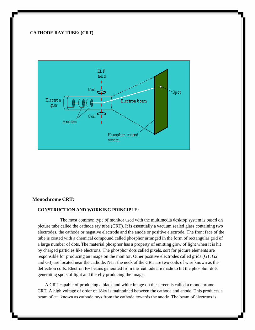
The most common type of monitor used with the multimedia desktop system is based on
picture tube called the cathode ray tube (CRT). It is essentially a vacuum sealed glass containing two
electrodes, the cathode or negative electrode and the anode or positive electrode. The front face of the
tube is coated with a chemical compound called phosphor arranged in the form of rectangular grid of
a large number of dots. The material phosphor has a property of emitting glow of light when it is hit
by charged particles like electrons. The phosphor dots called pixels, sort for picture elements are
responsible for producing an image on the monitor. Other positive electrodes called grids (G1, G2,
and G3) are located near the cathode. Near the neck of the CRT are two coils of wire known as the
deflection coils. Electron E− beams generated from the cathode are made to hit the phosphor dots
generating spots of light and thereby producing the image.
A CRT capable of producing a black and white image on the screen is called a monochrome
CRT. A high voltage of order of 18kv is maintained between the cathode and anode. This produces a
beam of e−, known as cathode rays from the cathode towards the anode. The beam of electrons is
controlled by 3 other positive terminals. The control grid G1, helps to control the amount of electrons
in the beam, the acceleration grid G2, provides acceleration of electrons in the forward direction and
focusing grid G3, focuses the beam to a single point ‗X‘ on the screen ahead, so that the diameter of
the beam is equal to the diameter of a single phosphor dot.
As the beam hits, the phosphor dot, a single glowing spot of light is created at the center of the
screen. This spot of light is known as glowing pixels. When current flow through the deflection coil,
the electric field produced interacts with the e− beam thereby deflecting it from its original path to
another point y.
One of the coils called the horizontal deflection coil moves the beam horizontally across the
screen & other coil called vertical deflection coil moves the beam vertically along the height of the
screen. When both these coils are energized required proportions the e− beam can be moved in any
direction. Thus generating a single spot of light at any point on the CRT screen.
COLOR CRT:

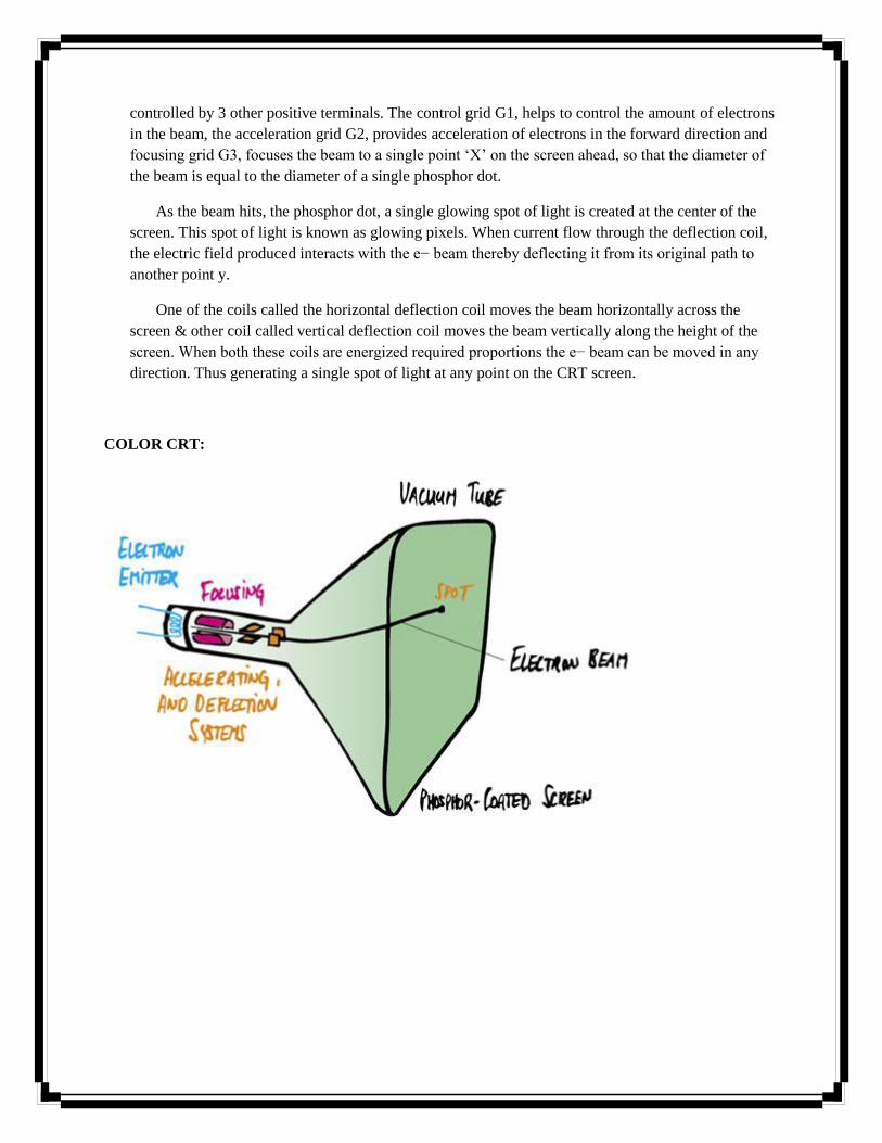
The working principle of a color CRT is similar to that of a monochrome CRT, except
that here each pixel consists of three colored dots instead of one and is called a triad. These processed
phosphor produce lights of color red, green and blue (RGB) and are called primary colors. These are
so called because it has been experimentally observed that these three colored lights can combine in
various proportions to produce all other colors.
Corresponding to the three dots these e− beams from the electrode (also called e−gun),
each of which falls on the corresponding dots in various intensity; they produce different proportions
of three elementary colored lights which mix together to create the sensation of a specific color in our
eyes.
A perforated screen called a shadow mask prevents the beam from the falling in the gap
between the dots. As the e− beam sweeps across the shadow mask, it gets heated up due to
e−bombardment on it. Expansion due to heating may disturb the alignment of the holes with the
phosphor dots, thereby causing the mask to lose its utility. To prevent this, the mask is made up of a
special alloy of Iron and nickel called invar which does not expand on heating.

VIDEO ADAPTER CARD:
Functions of an Adapter Card:
The video adapter card is an expansion card which usually sits on a slack on the
motherboard. It acts as the interface between the processor and the monitor. It accepts the data from
the processor through a communication channel called the bus, which connect to the slack. The card
communicates with the monitor via the adapter cable through a 15pin connectors.
The digital data required for creating an image on the screen is generated by the central
processor of the computer and consists of RGB values for each pixel on the screen. These are called
pixel attributes.
Earlier generation video cards can only passively transfer these data to the monitor and
were called flat video cards. For example, the adapter card can handle movement of an object on the
screen. For this involves changing existing pixel values, but to display a second object on the screen it
needs to get additional data from the processor.
Due to this additional capability, the modern video card releases computing and load
from the processor can display changing scenarios the presence of a processor chip on the card itself.
Thus, they are also referred to as accelerated video cards.
ESSENTIAL COMPONENTS FO A VIDEO ADAPTER CARD:
The video adapter card contains a number of essential components for converting the digital data
from the processor into analog signals before sending them to the monitor. The following are the
essential components of adapter card. They are
(i) Display memory
(ii) Graphics controller
(iii) Digital to Analog convertor.
Display Memory:
A bank of memory within the adapter card used for storing pixel attributes. Initially used
for storing the image data from the CPU and later used by the adapter to generate RGB signals for the
monitor. The amount of memory should be sufficient to hold the attributes of all the pixels on the
screen. The display memory is also known as Video RAM (VRAM).
Graphics controller:
A chip within the adapter card, responsible for co-coordinating the activities of all other
components of the card. For the earlier generation video cards, the controller simply passed on the
data from the processor to the monitor.
Digital to Analog converter :( DAC)
The DAC is one the main reason why the adapter is there. It takes the final digital data
from the VRAM and converts it to analog signals before sending those outwards to the monitor. Since
the electron guns of the monitor need voltage signals to generate electron beams, they would not be
able to function if digital data is directly fed to them. The digital data stored in the VRAM describes
the pixel attributes needed to drawn image on the monitor. The DAC converts these pixels values into
voltage signals.

VIDEO ADAPTER
CABLE:
The video adapter card is connected to the monitor with the video adapter cable. The cable plugs
to the card using a 15-pin connector. It carries the video signals (one for monochrome and three for color)
from the adapter card to the monitor where these are used to activate the e−beams of e−gun.
Additionally the cable also carries two synchronization signals(horizontally & vertical(
which are fed to the deflection coils on the neck of CRT to control the movement of the electron beams.
All these signals are generated by the adapter card in such a way that the monitor can reproduce the image
described by the pixel attributes stored in VRAM.
LIQUID CRYSTAL DISPLAY :( LCD)
The liquid crystal is a transparent organic substance consisting of long rod-like
molecules. It was found that the substance has properties for manipulating direction of light rays flowing
through it. This property is utilized for using it in display devices.
Advantage of the LCD is that its power consumption is much less than that of the CRT.
This makes it ideal to be operated by batteries. It is however much more expensive than the CRT and
more difficult to manufacture.

Construction and working principle:
An LCD monitor is a collection of LCD elements, each element generating a pixel
on the screen, analogous to the phosphor dots on a CRT screen. An LCD element consists of two
major components.
A layer of liquid crystal sandwiched between two finely grooved surfaces with their
grooves perpendicular to each other.
Two optical polarizing filters perpendicular to each other.
By flowing the liquid crystal over a finely grooved surface it is possible to control the
alignment of the modules as they follow the alignment of the grooves. A layer of liquid
crystal material is placed in a container with two finely grooved surfaces whose grooves
are perpendicular to each other and those at the intermediate layers are twisted by
intermediate angles.
Natural light waves are oriented at random angles and flow along various
plane from the light source. An optical polarizing filter or polarizes can involve a single
plane of light from the collection. The filter acts as a net of finely parallel lines blocking
all light except those flowing in a parallel to the lines. The light in this condition is said to
be polarized. A second polarized whose lines are perpendicular to the first would block
all the polarized light.
The container with grooved surfaces is placed in between two perpendicular
polarized filters. Normally light from the first filter would be blocked by the second filter.
However in this case, the liquid crystal material placed in between twists the plane of
light by 90 degrees as it passes through the material due to its molecular alignments. The
light now is parallel to the second filter and comes out wholly through it to the eye of the
observer. This constitutes a lighted pixel on the screen.
A battery connected across the liquid crystal container generates a current through
the liquid crystal, and re-orients its molecules according to the direction of the current
flow. This distributes the orderly pattern of the liquid crystal molecules; so that now the
molecules at the grooved surfaces are no longer emerge. An observer on the other side of
the filter does not see any light coming out. This arrangement creates a dark pixel.
PLASMA DISPLAY PANEL: (PDP)
Plasma is also called ionized gas. Plasma is an energetic gas-phase state of matter, often
referred to as ‗the fourth state of matter‘, in which some or all of the electrons in the outer atomic
orbital have become separated from the atom. The result is a collection of ions and electrons which
are no longer bound to each other. Because these particles are ionized (charged), the gas behaves in a
different fashion that neutral gas e.g., it can be affected by electromagnetic fields.
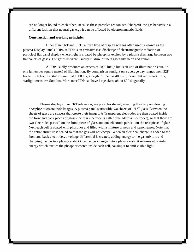
Construction and working principle:
Other than CRT and LCD, a third type of display screens often used is known as the
plasma Display Panel (PDP). A PDP is an emissive (i.e. discharge of electromagnetic radiation or
particles) flat panel display where light is created by phosphor excited by a plasma discharge between two
flat panels of gases. The gases used are usually mixture of inert gases like neon and xenon.
A PDP usually produces an excess of 1000 lux (a lux is an unit of illumination equal to
one lumen per square meter) of illumination. By comparison sunlight on a average day ranges from 32K
lux to 100k lux, TV studios are lit at 1000 lux, a bright office has 400 lux, moonlight represents 1 lux,
starlight measures 50m lux. More over PDP can have large sizes, about 80‖ diagonally.
Plasma displays, like CRT television, are phosphor-based, meaning they rely on glowing
phosphor to create their images. A plasma panel starts with two sheets of 1/16‖ glass. Between the
sheets of glass are spacers that create their images. A Transparent electrodes are then coated inside
the front and back pieces of glass (the rear electrode is called ‗the address electrode‘), so that there are
two electrodes per cell on the front piece of glass and one electrode per cell on the rear piece of glass.
Next each cell is coated with phosphor and filled with a mixture of neon and xenon gases. Note that
the entire structure is sealed so that the gas will not escape. When an electrical charge is added to the
front and back electrodes, a voltage differential is created, adding energy to the gas mixture and
changing the gas to a plasma state. Once the gas changes into a plasma state, it releases ultraviolet
energy which excites the phosphor coated inside each cell, causing it to emit visible light.
UNIT – II
Text: Introduction
In multimedia presentations, text can be combined with other media in a powerful way to
present information and express moods. Text can be of various types:
Plaintext, consisting of fixed sized characters having essentially the same type of
appearance.
Formatted text, where appearance can be changed using font parameters
Hypertext, which can serve to link different electronic documents and enable the user to
jump from one to the other in a non-linear way.
Internally text is represented via binary codes as per the ASCII table. The ASCII table is
however quite limited in its scope and a new standard has been developed to eventually replace
the ASCII standard. This standard is called the Unicode standard and is capable of representing
international characters from various languages throughout the world.
We also generate text automatically from a scanned version of a paper document or image
using Optical Character Recognition (OCR) software.
TYPES OF TEXT:
There are three types of text that can be used to produce pages of a document:
Unformatted text
Formatted text
Hypertext
I. Unformatted Text:
Also known as plaintext, this comprise of fixed sized characters from a limited character
set. The character set is called ASCII table which is short for American Standard Code for
Information Interchange and is one of the most widely used character sets. It basically consists of
a table where each character is represented by a unique 7-bit binary code. The characters include
a to z, A to Z, 0 to 9, and other punctuation characters like parenthesis, ampersand, single and
double quotes, mathematical operators, etc. All the characters are of the same height. In addition,
the ASCII character set also includes a number of control characters. These include BS

(backspace), LF (linefeed), CR (carriage return), SP (space), DEL (delete), ESC (escape), FF
(form feed) and others.
II. Formatted Text:
Formatted text are those where apart from the actual alphanumeric characters,
other control characters are used to change the appearance of the characters, e.g. bold,
underline, italics, varying shapes, sizes, and colors etc., Most text processing software use
such formatting options to change text appearance. It is also extensively used in the
publishing sector for the preparation of papers, books, magazines, journals, and so on.
III. Hypertext:
The term Hypertext is used to mean certain extra capabilities imparted to normal or
standard text. Like normal text, a hypertext document can be used to reconstruct knowledge
through sequential reading but additionally it can be used to link multiple documents in such
a way that the user can navigate non-sequentially from one document to the other for cross-
references. These links are called hyperlinks.
Microsoft Home Page
The underlined text string on which the user clicks the mouse is called an anchor
and the document which opens as a result of clicking is called the target document. On the
web target documents are specified by a specific nomenclature called Web site address
technically known as Uniform Resource Locators or URL.
Node or Anchor:
The anchor is the actual visual element (text) which provides an entry point to another
document. In most cases the appearance of the text is changed from the surrounding text to
designate a hypertext, e.g. by default it is colored blue with an underline. Moreover the mouse
pointer changes to a finger icon when placed over a hypertext. The user usually clicks over the
hypertext in order to activate it and open a new document in the document viewer. In some cases
instead of text an anchor can be an image, a video or some other non-textual element
(hypermedia).
Pointer or Link
These provide connection to other information units known as target documents. A link
has to be defined at the time of creating the hyperlink, so that when the user clicks on an anchor
the appropriate target document can be fetched and displayed. Usually some information about
the target document should be available to the user before clicking on the anchor. If the
destination is a text document, a short description of the content can be represented.
UNICODE STANDARD:
The Unicode standard is a new universal character coding scheme for written
characters and text. It defines a consistent way of encoding multilingual text which enables
textual data to be exchanged universally. The Unicode standard goes far beyond ASCII‘s limited
capability by providing the capacity of encoding more than 1 million characters. The Unicode
standard draws a distinction between characters, which are the smallest component of written
language, and glyphs, which represent the shapes, the characters can have when displayed.
Some of the languages and their corresponding codes are: Latin (00), Greek (03),
Arabic (06), Devanagari/Bengali (09), Oriya/Tamil (0B), etc. Several methods have been
suggested to implement Unicode based on variations in storage space and compatibility. The
mapping methods are called Unicode Transformation Formats (UTF) and Universal
Character Set (UCS). Some of the major mapping methods are:
a) UCS-4,UTF-32
Uses 32-bit for each character. The simplest scheme as it consists of fixed length
encoding, how it is not efficient with regard to storage space and memory usage, and therefore
rarely used. Initially the UCS-4 was proposed with a possible address range of 0 to
FFFFFFFFFF, but Unicode requires only upto 10FFFF.
b) UTF-16
A 16-bit encoding format. In its native format it can encode numbers upto FFFF, i.e, as
xxxxxxx xxxxxxx. For codings beyond this, the original number is expressed as a
combination of two 16-bit numbers.
c) UTF-8
The bits of a Unicode character is divided into a series of 8-bit numbers. The output code
against various ranges of input codes are given in Table 4.1
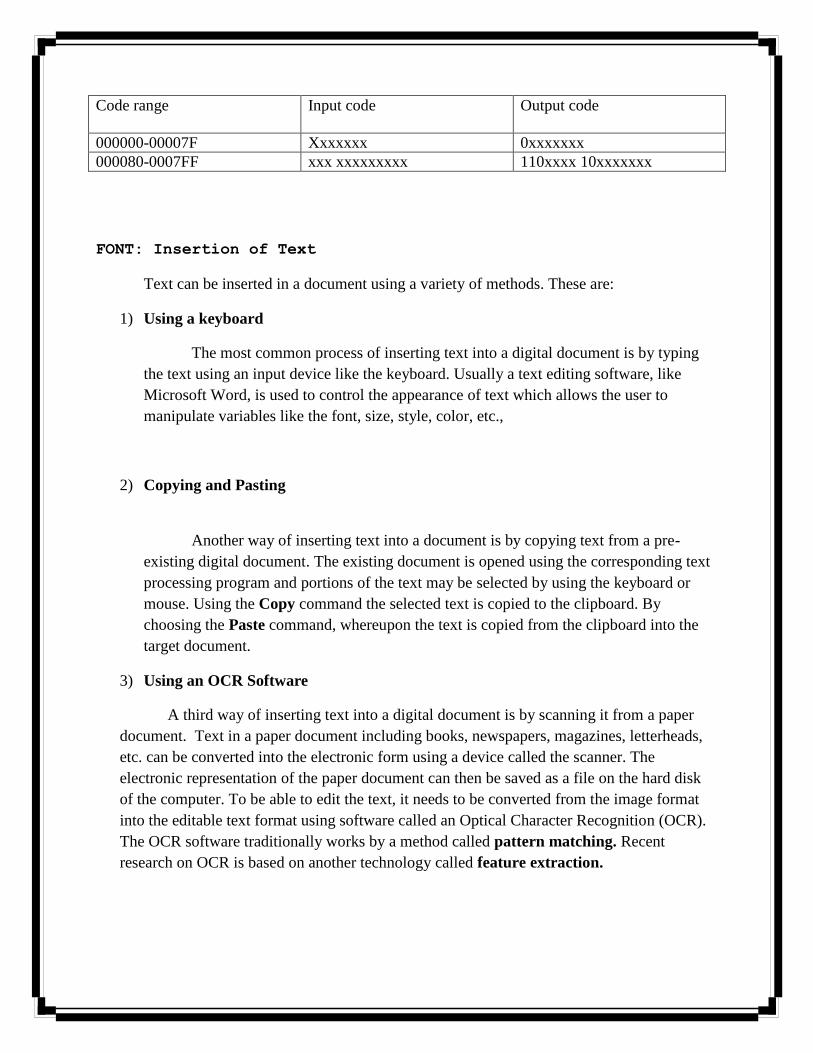
Code range Input code Output code
000000-00007F Xxxxxxx 0xxxxxxx
000080-0007FF xxx xxxxxxxxx 110xxxx 10xxxxxxx
FONT: Insertion of Text
Text can be inserted in a document using a variety of methods. These are:
1) Using a keyboard
The most common process of inserting text into a digital document is by typing
the text using an input device like the keyboard. Usually a text editing software, like
Microsoft Word, is used to control the appearance of text which allows the user to
manipulate variables like the font, size, style, color, etc.,
2) Copying and Pasting
Another way of inserting text into a document is by copying text from a pre-
existing digital document. The existing document is opened using the corresponding text
processing program and portions of the text may be selected by using the keyboard or
mouse. Using the Copy command the selected text is copied to the clipboard. By
choosing the Paste command, whereupon the text is copied from the clipboard into the
target document.
3) Using an OCR Software
A third way of inserting text into a digital document is by scanning it from a paper
document. Text in a paper document including books, newspapers, magazines, letterheads,
etc. can be converted into the electronic form using a device called the scanner. The
electronic representation of the paper document can then be saved as a file on the hard disk
of the computer. To be able to edit the text, it needs to be converted from the image format
into the editable text format using software called an Optical Character Recognition (OCR).
The OCR software traditionally works by a method called pattern matching. Recent
research on OCR is based on another technology called feature extraction.
TEXT COMPRESSION:
Large text documents covering a number of pages may take a lot of disk space.
We can apply compression algorithms to reduce the size of the text file during storage. A reverse
algorithm must be applied to decompress the file before its contents can be displayed on screen.
There are two types of compression methods that are applied to text as explained:
a. Huffman Coding:
This type of coding is intended for applications in which the text to be
compressed has known characteristics in terms of the characters used and their relative
frequencies of occurrences. An optimum set of variable-length code words is derived
such that the shortest code word is used to represent the most frequently occurring
characters. This approach is called the Huffman coding method.
b. Lempel-Ziv (LZ) Coding
In the second approach followed by the Lempel-Zir (LZ) method, instead of
using a single character as a basis of the coding operation, a string of characters is used.
For example, a table containing all the possible words that occur in a text document, is
held by both the encoder and decoder.
c. Lempel-Ziv-Welsh (LZW) Coding
Most word processing packages have a dictionary associated with them which is
used for both spell checking and compression of text. The variation of the above
algorithm called Lempel-Ziv-Welsh (LZW) method allows the dictionary to be built up
dynamically by the encoder and decoder for the document under processing.
FILE FORMATS:
The following text formats are usually used for textual documents.
TXT (Text)
Unformatted text document created by an editor like Notepad on Windows
platform. This documents can be used to transfer textual information between different
platforms like Windows, DOS, and UNIX,

DOC (Document)
Developed by Microsoft as a native format for storing documents created by the
MS Word package. Contains a rich set of formatting capabilities.
RTF (Rich Text Format)
Developed by Microsoft in 1987 for cross platform document exchanges. It is the
default format for Mac OS X‘s default editor TextEdit. RTF control codes are human
readable, similar to HTML code.
PDF (Portable Document Format)
Developed by Adobe Systems for cross platform exchange of documents. In
addition to text the format also supports images and graphics. PDF is an open standard
and anyone may write programs that can read and write PDFs without any associated
royalty charges.
PostScript (PS)
Postscript is a page description language used mainly for desktop publishing. A page
description language is a high-level language that can describe the contents of a page such that
it can be accurately displayed on output devices usually a printer. A PostScript interpreter inside
the printer converted the vercors backi into the raster dots to be printed. This allows arbitrary
scaling, rotating and other transformations.
IMAGES: INTRODUCTION
The pictures that we see in our everyday life can be broadly classified into two groups:
Images
Graphics
Images can either be pure black and white, or grayscale having a number of grey shades, or color
containing a number of color shades. Color is a sensation that light of different frequencies
generates on our eyes, the higher frequencies producing the blue end and the lower frequencies
producing the red end of the visible spectrum. White light is a combination of all the colors of
the spectrum. To recognize and communicate color information we need to have color models.
To recognize and communicate color information we need to have color models. The two most

well known color models are the RGB model used for colored lights like images on a monitor
screen, and the CMYK model used for colored inks like images printed on paper. One of the
most well known device independent color model is the HSB Model where the primaries are
hue, saturation and brightness. The total range of colors in a color model is known is its gamut.
The input stage deals with the issues of converting hardcopy paper images into electronic
versions. This is usually done via a device called the scanner. While scanners are used to digital
documents, another device called the digital camera can convert a real world scene into a digital
image. Digital camera can also contain a number of these electronic sensors which are known as
Charge-Couple Devices (CCD) and essentially operate on the same principle as the scanner.
This is the editing stage and involves operations like selecting, copying, scaling, rotating,
trimming, changing the brightness, contrast color tones, etc. of an image to transform it as per the
requirements of the application.The output stage involves saving the transformed image in a file
format which can be displayed on the monitor screen or printed on a printer. To save the image,
it is frequently compressed by a compression algorithm is ued the final image can be saved into a
variety of file formats.
IMAGE TYPES:
Images that we see in our everyday lives can be categorized into various types.
1. Hard Copy vs. Soft Copy
The typical images that we usually come across are the pictures that have been
printed on paper or some other kinds of surfaces like plastic, cloth, wood, etc. These are also
called hard copy images because they have been printed on solid surfaces. Such images have
been transformed from hard copy images or real objects into the electronic form using
specialized procedures and are referred to as soft copy images.
2. Continuous Tone, Half-tone and Bitone
Photographs are also known as continuous tone images because they are usually
composed of a large number of varying tones or shades of colors. Sometimes due to
limitations of the display or printed devices, all the colors of the photograph cannot be
represented adequately. In those cases a subset of the total number of colors of displayed.
Such images are called partial tone or half-tone images. A third category of images is called
bitonal images which uses only two colors, typically black and white, and do not use any
shades of grey.

SEEING COLOR:
The Phenomenon of seeing color is dependent on a triad of factors: the nature of light, the
interaction of light and matter, and the physiology of human version. Light is a form of energy
known as electromagnetic radiation. It consists of a large number of waves with varying
frequencies and wavelengths. Out of the total electromagnetic spectrum a small range of waves
cause sensations of light in our eyes. This is called the visible spectrum of waves.
The second part of the color triad is human vision. The retina is the light-sensitive part of
the eye and its surface is composed of photoreceptors or nerve endings.
The third factor is the interaction of light with matter. Whenever light waves strike an
object, part of the light energy gets absorbed and /or transmitted, while the remaining part gets
reflected back to our eyes.
Refraction Index(RI) is the ratio of the speed of light in a vaccum. A beam of
transmitted light changes direction according to the difference in refractive index and also the
angle at which it strikes the transparent object. This is called refraction. If light is only partly
transmitted by the object, the object is translucent.
COLOR MODELS:
Researchers have found out that most of the colors that we see around us can be
derived from mixing a few elementary colors. These elementary colors are known as primary
colors. Primary colors mixed in varying proportions produce other colors called composite
colors. Two primary colors mixed in equal proportions produce a secondary color. The primary
colors along with the total range of composite colors they can produce constitute a color model.
a) RGB Model
The RGB color model is used to describe behavior of colored lights like those
emitted from a TV screen or a computer monitor. This model has three primary colors:
red, green, blue, in short RGB.
Proportions of colors are determined by the beam strength. An electron beam
having the maximum intensity falling on a phosphor dot creates 100% of the
corresponding color.50% of the color results from a beam having the half the peak
strength. All three primary colors at full intensities combine together to produce white,
i.e. their brightness values are added up. Because of this the RGB model is called an
additive model. Lower intensity values produce shades of grey. A color present at 100%
of its intensity is called saturated, otherwise the color is said to be unsaturated.
b) CMYK Model
The RGB model is only valid for describing behavior of colored lights. This new
model is named CMYK model and is used to specify printed colors. The primary colors
of this model are cyan, magenta and yellow. These colors when mixed together in equal
proportions produce black, due to which the model is known as a subtractive model.
Mixing cyan and magenta in equal proportions produce blue, magenta and yellow
produce red, and yellow and cyan produce green. Thus, the secondary colors of the
CMYK model are the same as the primary colors of the RGB model and vice versa.
These two models are thus, known as complimentary models.
c) Device Dependency and Gamut
It is to be noted that both the RGB and the CMYK models do not have universal
or absolute color values. But different devices will give rise to slightly different sets of
colors. For this reason both the RGB and the CMYK models are known as device
dependent color models.
Another issue of concern here is the total range of colors supported by each color
model. This is known as the gamut of the model.
BASIC STEPS FOR IMAGE PROCESSING:
Image processing is the name given to the entire process involved with the input, editing
and output of images from a system. There are three basic steps:
a. Input
Image input is the first stage of image processing. It is concerned with getting
natural images into a computer system for subsequent work. Essentially it deals with the
conversion of analog images into digital forms using two devices. The first is the scanner
which can convert a printed image or document into the digital form. The second is the
digital camera which digitizes real-world images, similar to how a conventional camera
works.
b. Editing
After the images have been digitized and stored as files on the hard disk of a
computer, they are changed or manipulated to make them more suitable for specific
requirements. This step is called editing. Before the actual editing process can begin, and
important step called color calibration needs to be performed to ensure that the image
looks consistent when viewed on multiple monitors.
c. Output
Image output is the last stage in image processing concerned with displaying the
edited image to the user. The image can either be displayed in a stand-alone manner or as
part of some application like a presentation or web-page.
SCANNER
For images, digitization involves physical devices like the scanner or digital
camera. The scanner is a device used to convert analog images into the digital form. The most
common type of scanner for the office environment is called the flatbed scanner. The traditional
way of attaching a scanner to the computer is through an interface cable connected to the
parallel port of the PC.
Construction and Working principle:
To start a scanning operation, the paper document ot be scanned is placed face
down on the glass panel of the scanner, and the scanner is activated using a software from the
host computer. The light on getting reflected by the paper image is made to fall on a grid of
electronic sensors, by an arrangement of mirrors and lenses. The electronic sensors are called
Charge Coupled Devices (CCD) and are basically converters of the light energy into voltage
pulses. After a complete scan, the image is converted from a continuous entity into a discrete
form represented by a series of voltage pulses. This process is called sampling.
The voltage signals are temporarily stored in a buffer inside the scanner. The next step
called quantization involves representing the voltage pulses as binary numbers and carried out
by an ADC inside the scanner in conjuction with a software bundled with the scanner called the
scanning software.
Since each number has been derived from the intensity of the incident light, these
essentially represent brightness values at different points of the image and are known as pixels.
Scanner Types:

Scanners can be of various types each designed for specific purposes.
a. Flatbed scanners:
The flatbed scanner is the most common type in office environments and has been
described above. It looks like a photocopying machine with a glass panel on which the
document to be scanned is placed face down. Below the glass panel is a moving head
with a source of white light usually xenon lamps.
b. Drum Scanners:
Drum Scanner is used to obtain good quality scans for professional purposes and
generally provides a better performance than flatbed scanners. It consists of a cylindrical
drum made out of a highly translucent plastic like material. The fluid can either be oil-
based or alcohol-based. For the sensing element, drum scanners use a Photo-Multiplier
Tube (PMT) instead of a CCD. An amplifier gain of the order of 108
can be achieved in
multipliers containing about 14 dynode, which can provide measurable pulses from even
single photons.
c. Bar-code Scanners:
A barcode scanner is designed specifically to read barcodes printed on various
surfaces. A barcode is a machine-readable representation of information in a visual format.
Nowadays they come in other forms like dots and concentric circles. Barcodes relieve the
operator of typing strings in a computer, the encoded information is directly read by the
scanner. A LASER barcode scanner is more expensive that a LED one but is capable of
scanning barcodes at a distance of about 25cm. Most barcode scanners use the PS/2 port for
getting connected to the computer.
d. Color Scanning
Since the CCD elements are sensitive to the brightness of the light, the pixels
essentially store only the brightness information of the original image. This is also known as
luminance (or luma) information. To include the color or chrominance (or chroma)
information, there are three CCD elements for each pixel of image formed. White light
reflected off the paper document is split into the primary color components by a glass prism
and made to fall on the corresponding CCD sub-components.
e. Pixel Information:
To describe a color digital image, the pixels need to contain both the luma and the
chroma values, i.e. the complete RGB information of each color. To represent the orange
color we write: R=245 (96% of 255), G=102 (40% of 255), B=36 (14% of 255). This is
called a RGB triplet and notation for making it more compact, e.g. given below. These
values are also called RGB attributes of a pixel.
f. Scan quality:
The quality of a scanned image is determined mostly by its resolution and color
depth. The scanner resolution pertains to the resolution of the CCD elements inside a
scanner measured in dots per inch (dpi). Scanner resolution can be classified into two
categories; the optical resolution refers to the actual number of sensor elements per inch on
the scan head. Scanners however are often rated with resolution values higher than that of the
optical resolution e.g. 5400, 7200 or 9600dpi. These resolutions are called interpolated
resolutions and basically involve an interpolation process for generating new pixel values.
g. Scanning Software:
To scan an image, the user needs a scanning software to be installed on the computer
as in (fig) given below. The software lets the user interact with the scanner and set
parameters like bit depth and resolution. A typical scanning software should allow the user to
do the following:
i. Set the bit depth of the image file, which in turn determines the total number of
colors.
ii. Set the output path of the scanned image.
iii. Set the file type of the scanned image. Most scanners nowadays suppor the
standard file types like DMP, JPG, TIFF, etc.
iv. Adjust the brightness and contrast parameters usually by dragging sliders.
v. Change the size of the image by specifying a scale factor.
vi. Adjust the color of the scanned image by manipulating the amounts of red, green
and blue primaries.
vii. Adjust the resolution value.
The ‗final‘ button instructs the scanner to save the updated pixel values in a file
whose type and location have been previously specified.

DIGITAL CAMERA:
Construction and working principle:
Apart from the scanner used to digitize paper documents and film, another device
used to digitize real world images is the digital camera. Unlike a scanner a digital camera is
usually not attached to the computer via a cable. The camera has its own storage facility inside it
usually in the form of a floppy drive, which can save the image created into a floppy disc. So
instead they are compressed to reduce their file sizes and stored usually in the JPEG format.
This is a lossy compression technique and results in slight loss in image quality.
Most of the digital cameras have an LCD screen at eh back, which serve now
important purposes: first it can be used as a viewfinder for composition and adjustment; secondly
it can be used for viewing the images stored inside the camera. The recent innovation of built-in
microphones provides for sound annotation, in standard WAV format. After recording, this
sound can be sent to an external device for playback on headphones using an ear socket.
Storage and Software utility
Digital cameras also have a software utility resident in a ROM chip inside it which
allow the user to toggle between the CAMERA mode and PLAY mode. In the PLAY mode
the user is presented with a menu structure having some fo the functionalities like: displaying
all the images on the floppy , selecting a particular image, deleting selected images, write-
protecting the important image for deletion, setting the date and time, displaying how much
of the floppy disk space is free and even allowing a floppy to be formatted in the drive.
INTERFACE STANDARDS:
Interface standards determine how data from acquisition devices like scanners and
digital cameras flow to the computer in an efficient way. Refer fig.5.15. Two main interface
standards exists: TWAIN and ISIS.
i. TWAIN:
TWAIN is a very important standard in image acquisition, developed by Hewlett-
Packard, Kodak, Aldus, Logitech and Caere which specifies how image acquisition devices
such as scanners, digital cameras and other devices transfer data to software applications. It is
basically an image capture API for Microsoft Windows and Apple Macintosh platforms. The
standard was first released in 1992.

TWAIN is a software protocol which regulates the flow of information between
software applications and imaging devices like scanners. The standard is managed by the
TWAIN Working Group which is a non-profit organization with representative from leading
imaging vendors. The goals of the working group included: multiple platform support,
support for different types of devices like flatbed scanners, handheld scanners, image capture
boards, digital cameras, etc., provide a well-defined standard that gains support and
acceptance from leading hardware and software developers.
ii. Image and Scanner Interface Specification (ISIS)
The second important standard for document scanner is the Image and Scanner
Interface Specification (ISIS). It was developed by Pixel Translations and they retain control
over its development and licensing. ISIS has a wider set of features than TWAIN and
typically uses the SCSI-2 interface while TWAIN mostly uses the USB interface. Currently
ISIS compatible drivers are available for more than 250 scanner models most of them
certified by Pixel Translations.
IMAGE PROCESSING SOFTWARE
Image processing software offers a wide variety of ways to manipulate and
enhance images. We discuss below some of the salient features of a typical image processing
software.
i) Selection Tools:
Selection Tools enables us to select a specific potion out of an image and manipulate it or
copy it to another image. The selection border may be geomentrical in shape like rectangular,
circular, polygonal and may be irregular in shape. Selection may also be done based on color instead
of shapes.fig 5.22
ii) Painting and Drawing Tools
These tools are used to paint lines, shapes, etc. or fill regions with specified colors.
The colors are chosen from a color palette or specified by their RGB values.fig 5.23
iii) Color Selection Tools
These tools are used to select foreground and background colors from a color palette.
They also usually allow specifying colors by their RGB values.fig 5.24
iv) Gradient Tools
Gradient Tools are used to create smooth blends of multiple colors. Gradients may be
of various shapes like linear, radial, diamond-shaped, etc.fig 5.25
v) Clone Tools
Clone Tools are used to create multiple copies of specific features in an image.
They are also used to select specific patterns and apply them repeatedly over an
image. Fig5.26
vi) Transformation Tools
These tools are used to transform specific portions of an image in various ways
like moving, rotating, scaling, skewing, distorting, etc. fig 5.27
vii) Retouching Tools
These tools are used to change brightness/contrast of the image as well as color hues.
Specific portions of the image may be desaturated, i.e. converted to grayscale. Parts of
the image may also be blurred or sharpened. Fig 5.28
viii) Text Tools
These tools allow the user to include text in various styles and sizes. The text may
have different colors and orientations. Fig 5.29
ix) Changing Image Characteristics
Image processing software allows images to be opened and saved in various file
formats. Operations like changing image dimensions, color depth and resolution are also
allowed. When the resolution of an image is modified using image processing software the
total number of pixels is changed. In cases where the resolution is increased, e.g. converting
from 72dpi to 300dpi, extra pixels needs to be generated by the software.
x) Indexed color
The term refers to a type of images usually with a limited number of color values e.g.
256. A color lookup table (CLUT) is used to store and index the color values of the
image. Within the image file, instead of storing the actual RGB values, the index number
of the row containing the specific color value is stored.
FILE FORMATS:
Images may be stored in a variety of file formats. Each file format is characterized
by a specific compression type and color depth. The choice of file formats would depend on the
final image quality required and the import capabilities of the authoring system. The most
popular file formats are:
1) BMP (Bitmap)
BMP is a standard Windows compatible computer. BMP formats supports RGB,
Indexed Color, Grey scale and Bitmap color modes, and does not support alpha channels.
2) JPEG (Joint Photographers Expert Group)
Joint Photographers Expert Group (JPEG) format is commonly used to display
photographs and other continuous-tone images in hypertext markup language (HTML)
documents over the World Wide Web and other online services.
3) GIF (Graphics Interchange Format)
Graphics Interchange Format (GIF) is the file format commonly used to display
indexed color graphics and images in hypertext markup language (HTML) document
over the World Wide Web and other online services.
4) TIFF (Tagged Image File Format)
Tagged Image File Format (TIFF) designed by Aldus Corporation and Microsoft
in 1987, is used to exchange files between applications and computer platforms. TIFF is a
flexible bitmap image format supported by virtually all paint, image-editing and page
layout applications.
5) PNG (Portable Network Graphics)
Developed as a patent-free alternative to GIF, Portable Network Graphics (PNG)
format is used for lossless compression and for display of images on the World Wide Web.
6) PICT (Picture)
PICT format is widely used among Mac OS graphics and page-layout applications as
an intermediatary file format for transferring images between applications. PICT format is
especially effective at compression images with large areas of solid color.
7) TGA (Targa)
Targa (TGA) format is designed for systems using the True vision video board and is
commonly supported by MS-DOS color applications. This format supports 24-bit RGB
images.
8) PSD (Photoshop Document)
Photoshop (PSD) format is a default file format used in the Adobe Photoshop
package and the only format supporting all available image modes.
IMAGE OUTPUT ON MONITOR
The image pixels are actually strings of binary numbers and therefore may be
referred to as logical pixels. When the images are displayed on the monitor however, the logical
pixels are directly mapped on to the phosphor dots of the monitor, which may be referred to as
physical pixels.
Dependence on Monitor Resolution
Let us consider an image having dimensions 1 inch by 1 inch and a resolution of
72ppi. Thus, the image is made up of 72 logical pixels horizontally and 72 logical pixels
vertically. The monitor resolution in this case is equal to the image resolution.

Let us consider an image be rescanned at a high resolution of 144ppi. Thus, the image
is made up of 144 logical pixels. The monitor resolution is however unchanged at 72dpi. The
monitor resolution in this case is less to the image resolution.
On the other hand if the image resolution decreases to 30ppi, internally 1 inch of the
image will consist of 30 logical pixels. The monitor resolution in this case is more than the
image resolution and makes the image look smaller.
Dependence on Monitor Size
Let us consider a 15‖ monitor which displays 640 pixels horizontally and 480
pixels vertically. An image with pixel dimensions of 640X480 would fill up the entire screen. If
the viewing mode of the 20‖ Monitor is increased to 800 by 600 then the image will occupy only
a portion of the screen as the available number of pixels is more than that required for displaying
the image.
IMAGE OUTPUT ON PRINTER
Though there are a large variety of printers in the industry, two types are mostly
used for printing multimedia content: the LASER printer and the Inkjet printer. The number of
dots printed per inch of the printed page is called the printer resolution and expressed as dots
per inch. Thus based on the final purpose the image needs to be created or scanned at the
appropriate resolution.
LASER Printer
The LASER printer was introduced by Hewlett-Packard in 1984, based on technology
developed by Canon. It worked in a similar way to a photocopier, the difference being the
light source. LASER printers quickly became popular due the high quality of their print and
low running costs.
Inkjet Printer
Inkjet printers, like LASER printers, employ a non-impact method meaning that there
is no head or hammer striking the paper to produce the print, like typewriters or the
dot-matrix printer. Ink is emitted from nozzles as they pass over a variety of possible
media.
i) Thermal technology
Most inkjets use thermal technology, whereby heat is used to fire ink onto
the paper. There are three main stages with this method. The ink emission is initiated

by heating the ink to create a bubble until the pressure forces it to burst and hit the
paper. This is the method favored by Canon and Hewlett-Packard. This imposes
certain limitations on the printing process in that whatever type of ink is used, it must
be resistant to heat because the firing process is heat-based.
ii) Piezo-electric Technology
Epson‘s proprietary piezo-electric technology uses a piezo crystal at the back
of the ink reservoir. It uses the property of certain crystals that causes them to
oscillate when subjected to electrical pressure (voltage). There are several
advantages to eh piezo method. This allows more freedom for developing new
chemical properties on ink.
iii) Inks
The ink is used in inkjet technology is water-based and this poses a few
problems. Oil based ink is not really a solution to the problem because it would
impose a far higher maintenance cost on the hardware. Printer manufacturers are
making continual progress in the development of water-resistant inks, but the
print quality from inkjet printers are still weak compared to LASER printers.
UNIT –III
CHARACTERISTICS OF SOUND:
Sound waves travel at great distances in a very short time, but as the distance increases the
waves tend to spread out. As the sound waves spread out, their energy simultaneously spreads through
an increasingly larger area. Thus, the wave energy becomes weaker as the distance from the source is
increased. Sounds may be broadly classified into two general groups. One group is NOISE, which
includes sounds such as the pounding of a hammer or the slamming of a door. The other group is
musical sounds, or TONES. The distinction between noise and tone is based on the regularity of the
vibrations, the degree of damping, and the ability of the ear to recognize components having a musical
sequence. You can best understand the physical difference between these kinds of sound by comparing
the wave shape of a musical note, depicted in view A of figure 1-13, with the wave shape of noise,
shown in view B. You can see by the comparison of the two wave shapes, that noise makes a very
irregular and haphazard curve and a musical note makes a uniform and regular curve.
Basic Characteristics of Sound
In this information Age, the quest and journey for knowledge is something we all spend a
lot of time doing. Well, I don‘t know about you but sometimes I simply do not understand
something when it is presented in only one way and so I search for other means to gain the
understanding and knowledge I seek. As a result, I wander around scratching my head pondering
and wondering, all the while not understanding what was being taught in that moment, until such
time as new information comes along and all of a sudden the itch of wonder is replaced by
knowledge and certainty.
Understanding sound and the characteristics of sound can be more easily learned in that same
way. There are several concepts that are difficult to understand in music unless they are
presented in more than one way too. Hopefully this article will help you to understand the basics
of sound more fully by this multi-focused approach. It is through an understanding of the
characteristics that make up sound that you can more fully appreciate what you listen to, but
more so, gain an understanding of some of the basic tools a composer considers and uses when
creating a piece of music.
After all, music is actually and simply sound and sound has only four characteristics. When we
arrange these characteristics in such a way that we find it pleasing to listen to we call that music.
The basic fundamentals of music are by their very nature a necessary tool to use in many of the
future papers I will be presenting over time. The fundamental characteristics of sound consist of
only; pitch, duration, quality and intensity, however, the character of the sequence of sounds and
its arrangement is what makes music subjectively pleasing and individually enjoyed. Let‘s take a
closer look at these four basic characteristics that comprise the foundation for everything else we
will be discussing, as related to music.
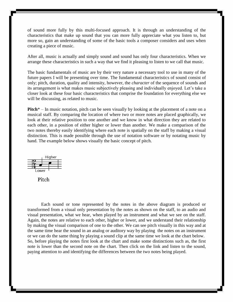
Pitch* – In music notation, pitch can be seen visually by looking at the placement of a note on a
musical staff. By comparing the location of where two or more notes are placed graphically, we
look at their relative position to one another and we know in what direction they are related to
each other, in a position of either higher or lower than another. We make a comparison of the
two notes thereby easily identifying where each note is spatially on the staff by making a visual
distinction. This is made possible through the use of notation software or by notating music by
hand. The example below shows visually the basic concept of pitch.
Each sound or tone represented by the notes in the above diagram is produced or
transformed from a visual only presentation by the notes as shown on the staff, to an audio and
visual presentation, what we hear, when played by an instrument and what we see on the staff.
Again, the notes are relative to each other, higher or lower, and we understand their relationship
by making the visual comparison of one to the other. We can see pitch visually in this way and at
the same time hear the sound in an analog or auditory way by playing the notes on an instrument
or we can do the same thing by playing a sound clip at the same time we look at the chart below.
So, before playing the notes first look at the chart and make some distinctions such as, the first
note is lower than the second note on the chart. Then click on the link and listen to the sound,
paying attention to and identifying the differences between the two notes being played.
In essence, we have two methods of determining pitch using our senses, sight and
hearing. We will limit our understanding to these two senses at this time, unless you are so
inclined to pull out your musical instrument and play the notes now. By doing this you can
experience the notes in three senses; hearing, sight and tactile feeling. However, it is important to
know that through a multiple sensory approach such as this we can learn to associate the sound
of the note on the staff and in reverse hear the note and learn how to notate music. We can also
learn to sing from this basis too.
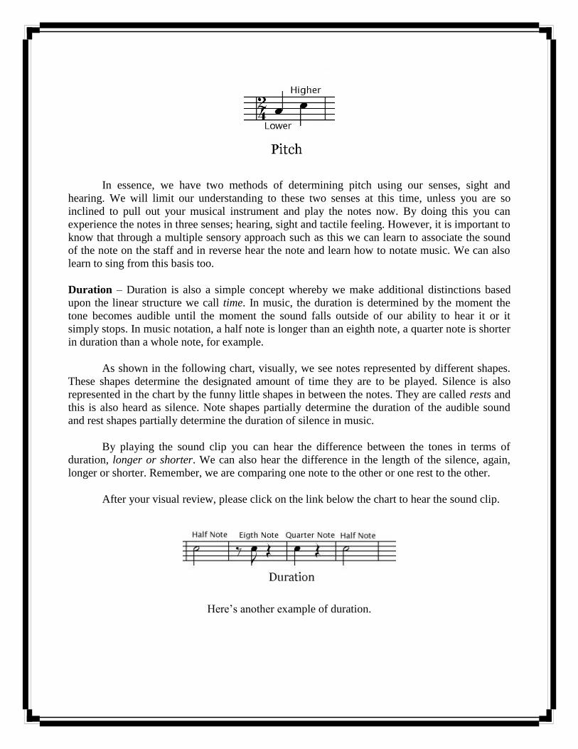
Duration – Duration is also a simple concept whereby we make additional distinctions based
upon the linear structure we call time. In music, the duration is determined by the moment the
tone becomes audible until the moment the sound falls outside of our ability to hear it or it
simply stops. In music notation, a half note is longer than an eighth note, a quarter note is shorter
in duration than a whole note, for example.
As shown in the following chart, visually, we see notes represented by different shapes.
These shapes determine the designated amount of time they are to be played. Silence is also
represented in the chart by the funny little shapes in between the notes. They are called rests and
this is also heard as silence. Note shapes partially determine the duration of the audible sound
and rest shapes partially determine the duration of silence in music.
By playing the sound clip you can hear the difference between the tones in terms of
duration, longer or shorter. We can also hear the difference in the length of the silence, again,
longer or shorter. Remember, we are comparing one note to the other or one rest to the other.
After your visual review, please click on the link below the chart to hear the sound clip.
Here‘s another example of duration.
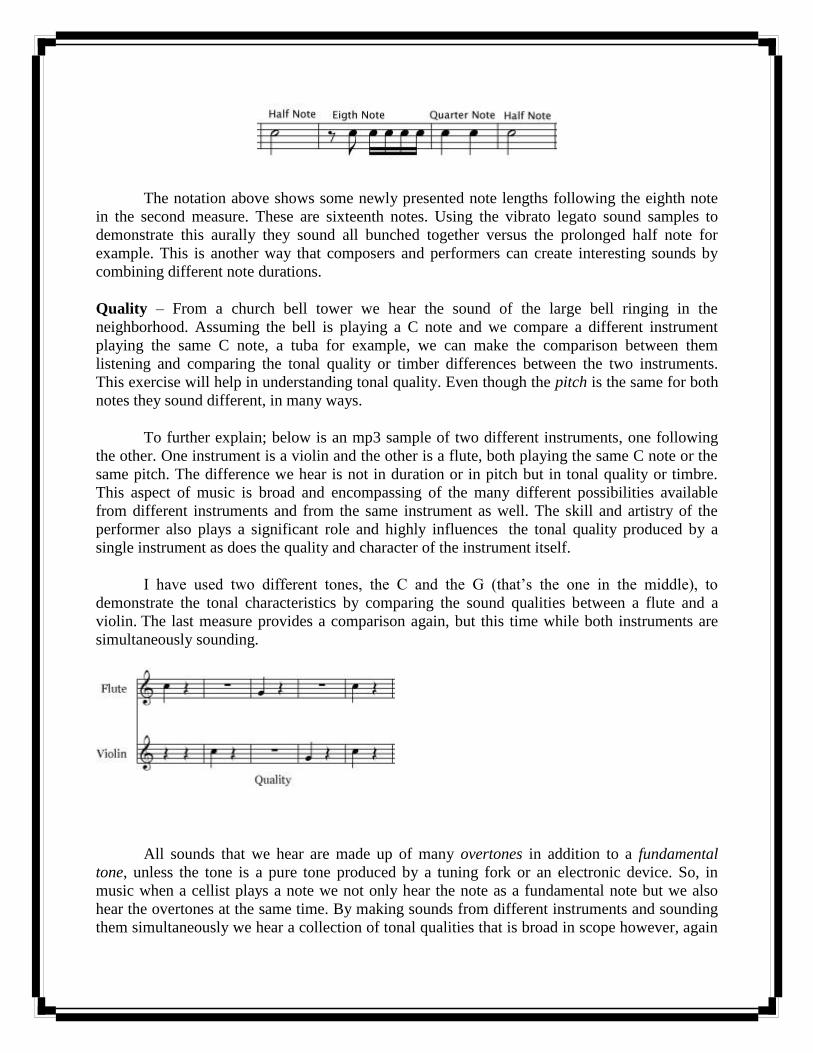
The notation above shows some newly presented note lengths following the eighth note
in the second measure. These are sixteenth notes. Using the vibrato legato sound samples to
demonstrate this aurally they sound all bunched together versus the prolonged half note for
example. This is another way that composers and performers can create interesting sounds by
combining different note durations.
Quality – From a church bell tower we hear the sound of the large bell ringing in the
neighborhood. Assuming the bell is playing a C note and we compare a different instrument
playing the same C note, a tuba for example, we can make the comparison between them
listening and comparing the tonal quality or timber differences between the two instruments.
This exercise will help in understanding tonal quality. Even though the pitch is the same for both
notes they sound different, in many ways.
To further explain; below is an mp3 sample of two different instruments, one following
the other. One instrument is a violin and the other is a flute, both playing the same C note or the
same pitch. The difference we hear is not in duration or in pitch but in tonal quality or timbre.
This aspect of music is broad and encompassing of the many different possibilities available
from different instruments and from the same instrument as well. The skill and artistry of the
performer also plays a significant role and highly influences the tonal quality produced by a
single instrument as does the quality and character of the instrument itself.
I have used two different tones, the C and the G (that‘s the one in the middle), to
demonstrate the tonal characteristics by comparing the sound qualities between a flute and a
violin. The last measure provides a comparison again, but this time while both instruments are
simultaneously sounding.
All sounds that we hear are made up of many overtones in addition to a fundamental
tone, unless the tone is a pure tone produced by a tuning fork or an electronic device. So, in
music when a cellist plays a note we not only hear the note as a fundamental note but we also
hear the overtones at the same time. By making sounds from different instruments and sounding
them simultaneously we hear a collection of tonal qualities that is broad in scope however, again

we still primarily hear the loudest or the fundamental tone. The spectral analysis photo below
demonstrates this point.
Spectral Analysis
Each peak is not simply a vertical line. It has many more nuances and sounds making up
the total sound we hear. The photo shows this where in between each peak we see a lot of
smaller peaks and the width of the main peaks is broad, partly contingent upon intensity and
partly on overtones.
Note: Tonal quality and overtones can be further understood visually by taking a closer look at
the first picture in this article. It is reproduced here for convenience.
3D Sound Spectrum
The concept of and study of overtones and other sound mechanisms takes us to material
and information beyond the scope of this article. Our intention here is to provide the basic
understanding of the difference in tonal quality as compared to intensity, duration and pitch.
Intensity – Intensity is a measure of the loudness of the tone. Assuming that the pitch, duration
and tonal quality are the same, we compare two or more tones based upon loudness or intensity.
One is louder or quieter than the other. When playing a piano for instance, if we strike the keys
gently we produce a quiet sound. If we strike them hard we produce a louder sound even though
the pitch is the same. Here is an audio clip comparing intensity or loudness on the flute.
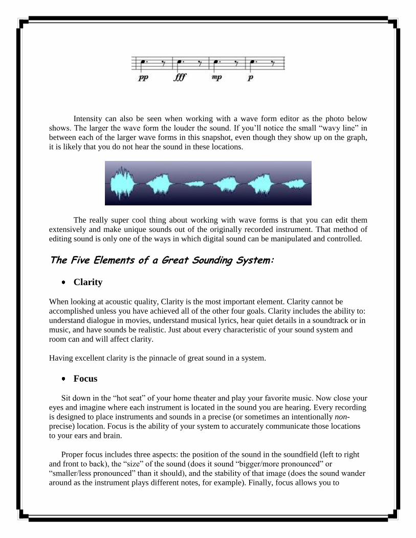
Intensity can also be seen when working with a wave form editor as the photo below
shows. The larger the wave form the louder the sound. If you‘ll notice the small ―wavy line‖ in
between each of the larger wave forms in this snapshot, even though they show up on the graph,
it is likely that you do not hear the sound in these locations.
The really super cool thing about working with wave forms is that you can edit them
extensively and make unique sounds out of the originally recorded instrument. That method of
editing sound is only one of the ways in which digital sound can be manipulated and controlled.
The Five Elements of a Great Sounding System:
Clarity
When looking at acoustic quality, Clarity is the most important element. Clarity cannot be
accomplished unless you have achieved all of the other four goals. Clarity includes the ability to:
understand dialogue in movies, understand musical lyrics, hear quiet details in a soundtrack or in
music, and have sounds be realistic. Just about every characteristic of your sound system and
room can and will affect clarity.
Having excellent clarity is the pinnacle of great sound in a system.
Focus
Sit down in the ―hot seat‖ of your home theater and play your favorite music. Now close your
eyes and imagine where each instrument is located in the sound you are hearing. Every recording
is designed to place instruments and sounds in a precise (or sometimes an intentionally non-
precise) location. Focus is the ability of your system to accurately communicate those locations
to your ears and brain.
Proper focus includes three aspects: the position of the sound in the soundfield (left to right
and front to back), the ―size‖ of the sound (does it sound ―bigger/more pronounced‖ or
―smaller/less pronounced‖ than it should), and the stability of that image (does the sound wander
around as the instrument plays different notes, for example). Finally, focus allows you to
distinguish between different sounds in the recording, assuming the recording was done in a way
that the sounds are actually distinguishable!
Envelopment
Envelopment refers to how well your system can ―surround‖ you with the sound. You may
be surprised, but a well designed and calibrated system with only two speakers is still well
capable of surrounding you with sound. A well done 5.1 or 7.1 system will do it even better.
Proper envelopment means a 360-degree soundfield with no holes or hotspots, accurate
placement of sounds within that soundfield, and the ability to accurately reproduce the sound of
the room where the recording was made.
Dynamic Range
The difference between the softest sound and loudest sound a system can reproduce is it‘s
dynamic range. Most people focus on bumping up the loud side of things (with bigger amps,
etc.). The reality is that the dynamic range of many home theaters is limited by the quietest
sounds. The softest sounds can be buried under excessive ambient noise - whether it‘s fan noise,
A/C noise, DVR hard drives, the kitchen refrigerator in the next room, or cars driving by outside
the window.
The goal for dynamic range is to easily & effortlessly reproduce loud sounds while still
ensuring that quiet sounds can be easily heard.
Response
A system‘s response is a measurement of how equally every frequency is played by the system.
The goal is a smooth response from the very low end (bass) all the way up to the highest (treble)
frequencies. Examples of uneven response include:
Boomy bass: certain bass notes knocking you out of your chair while others even a few notes higher or lower can barely be heard
Not enough bass overall Instruments sounding “wrong” Things sounding just generally unrealistic A system that is tiring to listen to, causing “listener fatigue” after only a short time.
A properly tuned system will sound smooth across all frequencies, will not cause fatigue
even at higher volumes, and will result in instruments and other acoustic elements sounding
natural and realistic.

Microphones:
I. How They Work. II. Specifications. III. Pick Up Patterns IV. Typical Placement V. The Microphone Mystique
I. How They Work.
A microphone is an example of a transducer, a device that changes information from one form to
another. Sound information exists as patterns of air pressure; the microphone changes this
information into patterns of electric current. The recording engineer is interested in the accuracy
of this transformation, a concept he thinks of as fidelity.
A variety of mechanical techniques can be used in building microphones. The two most
commonly encountered in recording studios are the magneto-dynamic and the variable condenser
designs.
THE DYNAMIC MICROPHONE.
In the magneto-dynamic, commonly called dynamic, microphone, sound waves cause
movement of a thin metallic diaphragm and an attached coil of wire. A magnet produces a
magnetic field which surrounds the coil, and motion of the coil within this field causes current to
flow. The principles are the same as those that produce electricity at the utility company, realized
in a pocket-sized scale. It is important to remember that current is produced by the motion of the
diaphragm, and that the amount of current is determined by the speed of that motion. This kind
of microphone is known as velocity sensitive.

THE CONDENSER MICROPHONE.
In a condenser microphone, the diaphragm is mounted close to, but not touching, a rigid
backplate. (The plate may or may not have holes in it.) A battery is connected to both pieces of
metal, which produces an electrical potential, or charge, between them. The amount of charge is
determined by the voltage of the battery, the area of the diaphragm and backplate, and the
distance between the two. This distance changes as the diaphragm moves in response to sound.
When the distance changes, current flows in the wire as the battery maintains the correct charge.
The amount of current is essentially proportioinal to the displacement of the diaphragm, and is
so small that it must be electrically amplified before it leaves the microphone.
A common varient of this design uses a material with a permanently imprinted charge for
the diaphragm. Such a material is called an electret and is usually a kind of plastic. (You often
get a piece of plastic with a permanent charge on it when you unwrap a record. Most plastics
conduct electricity when they are hot but are insulators when they cool.) Plastic is a pretty good
material for making diaphragms since it can be dependably produced to fairly exact
specifications. (Some popular dynamic microphones use plastic diaphragms.) The major
disadvantage of electrets is that they lose their charge after a few years and cease to work.
II. Specifications
There is no inherent advantage in fidelity of one type of microphone over another.
Condenser types require batteries or power from the mixing console to operate, which is
occasionally a hassle, and dynamics require shielding from stray magnetic fields, which makes
them a bit heavy sometmes, but very fine microphones are available of both styles. The most
important factor in choosing a microphone is how it sounds in the required application. The
following issues must be considered:
Sensitivity.
This is a measure of how much electrical output is produced by a given sound. This is a vital
specification if you are trying to record very tiny sounds, such as a turtle snapping its jaw, but
should be considered in any situation. If you put an insensitive mic on a quiet instrument, such as
an acoustic guitar, you will have to increase the gain of the mixing console, adding noise to the
mix. On the other hand, a very sensitive mic on vocals might overload the input electronics of
the mixer or tape deck, producing distortion.
Overload characteristics.
Any microphone will produce distortion when it is overdriven by loud sounds. This is caused
by varous factors. With a dymanic, the coil may be pulled out of the magnetic field; in a
condenser, the internal amplifier might clip. Sustained overdriving or extremely loud sounds can
permanently distort the diaphragm, degrading performance at ordinary sound levels. Loud
sounds are encountered more often than you might think, especially if you place the mic very
close to instruments. (Would you put your ear in the bell of a trumpet?) You usually get a choice
between high sensitivity and high overload points, although occasionally there is a switch on the
microphone for different situations.
Linearity, or Distortion.
This is the feature that runs up the price of microphones. The distortion characteristics of
a mic are determined mostly by the care with which the diaphragm is made and mounted. High
volume production methods can turn out an adequate microphone, but the distortion performance
will be a matter of luck. Many manufacturers have several model numbers for what is essentially
the same device. They build a batch, and then test the mics and charge a premium price for the
good ones. The really big names throw away mic capsules that don't meet their standards. (If you
buy one Neumann mic, you are paying for five!)
No mic is perfectly linear; the best you can do is find one with distortion that
complements the sound you are trying to record. This is one of the factors of the microphone
mystique discussed later.
Frequency response.
A flat frequency response has been the main goal of microphone companies for the last
three or four decades. In the fifties, mics were so bad that console manufacturers began adding
equalizers to each input to compensate. This effort has now paid off to the point were most
professional microphones are respectably flat, at least for sounds originating in front. The major
exceptions are mics with deliberate emphasis at certain frequencies that are useful for some
applications. This is another part of the microphone mystique. Problems in frequency response
are mostly encountered with sounds originating behind the mic, as discussed in the next section.
Noise.
Microphones produce a very small amount of current, which makes sense when you
consider just how light the moving parts must be to accurately follow sound waves. To be useful
for recording or other electronic processes, the signal must be amplified by a factor of over a

thousand. Any electrical noise produced by the microphone will also be amplified, so even slight
amounts are intolerable. Dynamic microphones are essentially noise free, but the electronic
circuit built into condensor types is a potential source of trouble, and must be carefully designed
and constructed of premium parts.
Noise also includes unwanted pickup of mechanical vibration through the body of the
microphone. Very sensitive designs require elastic shock mountings, and mics intended to be
held in the hand need to have such mountings built inside the shell.
The most common source of noise associated with microphones is the wire connecting
the mic to the console or tape deck. A mic preamp is very similar to a radio reciever, so the cable
must be prevented from becoming an antenna. The basic technique is to surround the wires that
carry the current to and from the mic with a flexible metallic shield, which deflects most radio
energy. A second technique, which is more effective for the low frequency hum induced by the
power company into our environment, is to balance the line:
Current produced by the microphone will flow down one wire of the twisted pair, and back along
the other one. Any current induced in the cable from an outside source would tend to flow the
same way in both wires, and such currents cancel each other in the transformers. This system is
expensive.
Microphone Levels
As I said, microphone outputs are of necessity very weak signals, generally around -60dBm.
(The specification is the power produced by a sound pressure of 10 uBar) The output impedance
will depend on whether the mic has a transformer balanced output . If it does not, the
microphone will be labeled "high impedance" or "hi Z" and must be connected to an appropriate
input. The cable used must be kept short, less than 10 feet or so, to avoid noise problems.
If a microphone has a transformer, it will be labeled low impedance, and will work best
with a balanced input mic preamp. The cable can be several hundred feet long with no problem.
Balanced output, low impedance microphones are expensive, and generally found in professonal
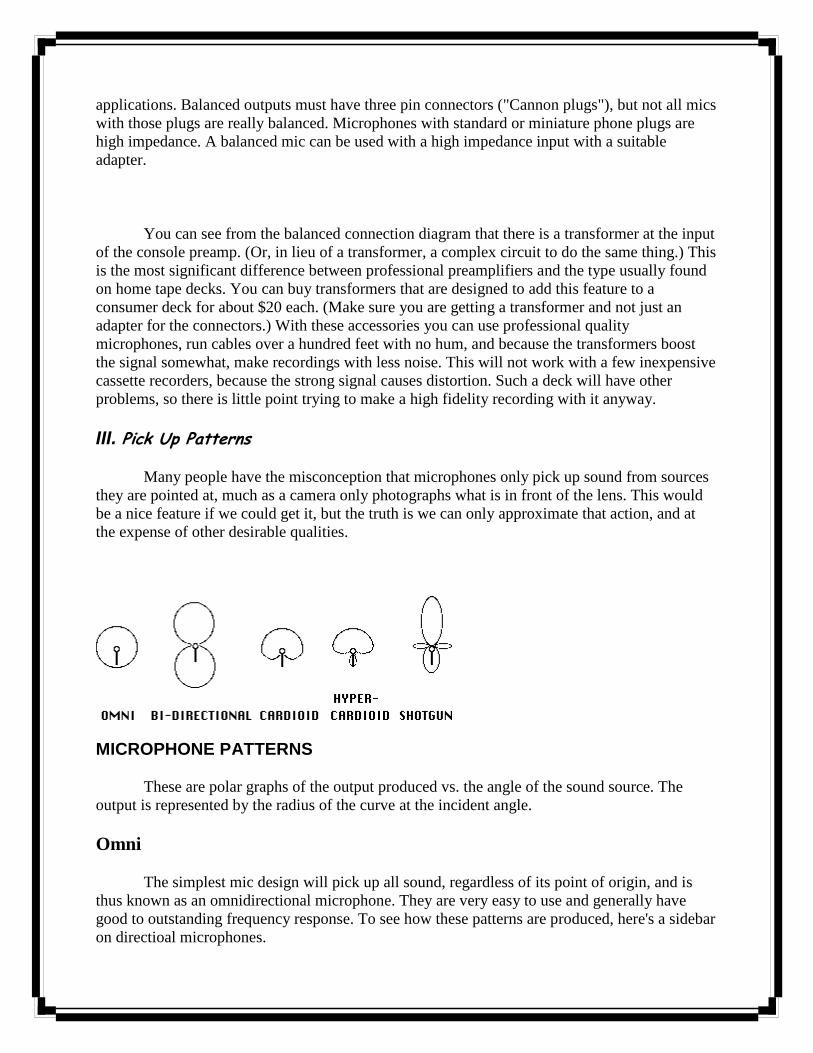
applications. Balanced outputs must have three pin connectors ("Cannon plugs"), but not all mics
with those plugs are really balanced. Microphones with standard or miniature phone plugs are
high impedance. A balanced mic can be used with a high impedance input with a suitable
adapter.
You can see from the balanced connection diagram that there is a transformer at the input
of the console preamp. (Or, in lieu of a transformer, a complex circuit to do the same thing.) This
is the most significant difference between professional preamplifiers and the type usually found
on home tape decks. You can buy transformers that are designed to add this feature to a
consumer deck for about $20 each. (Make sure you are getting a transformer and not just an
adapter for the connectors.) With these accessories you can use professional quality
microphones, run cables over a hundred feet with no hum, and because the transformers boost
the signal somewhat, make recordings with less noise. This will not work with a few inexpensive
cassette recorders, because the strong signal causes distortion. Such a deck will have other
problems, so there is little point trying to make a high fidelity recording with it anyway.
III. Pick Up Patterns
Many people have the misconception that microphones only pick up sound from sources
they are pointed at, much as a camera only photographs what is in front of the lens. This would
be a nice feature if we could get it, but the truth is we can only approximate that action, and at
the expense of other desirable qualities.
MICROPHONE PATTERNS
These are polar graphs of the output produced vs. the angle of the sound source. The
output is represented by the radius of the curve at the incident angle.
Omni
The simplest mic design will pick up all sound, regardless of its point of origin, and is
thus known as an omnidirectional microphone. They are very easy to use and generally have
good to outstanding frequency response. To see how these patterns are produced, here's a sidebar
on directioal microphones.

Bi-directional
It is not very difficult to produce a pickup pattern that accepts sound striking the front or
rear of the diaphragm, but does not respond to sound from the sides. This is the way any
diaphragm will behave if sound can strike the front and back equally. The rejection of undesired
sound is the best achievable with any design, but the fact that the mic accepts sound from both
ends makes it difficult to use in many situations. Most often it is placed above an instrument.
Frequency response is just as good as an omni, at least for sounds that are not too close to the
microphone.
Cardioid
This pattern is popular for sound reinforcement or recording concerts where audience
noise is a possible problem. The concept is great, a mic that picks up sounds it is pointed at. The
reality is different. The first problem is that sounds from the back are not completely rejected,
but merely reduced about 10-30 dB. This can surprise careless users. The second problem, and a
severe one, is that the actual shape of the pickup pattern varies with frequency. For low
frequencies, this is an omnidirectional microphone. A mic that is directional in the range of bass
instruments will be fairly large and expensive. Furthermore, the frequency response for signals
arriving from the back and sides will be uneven; this adds an undesired coloration to instruments
at the edge of a large ensemble, or to the reverberation of the concert hall.
A third effect, which may be a problem or may be a desired feature, is that the
microphone will emphasize the low frequency components of any source that is very close to the
diaphragm. This is known as the "proximity effect", and many singers and radio announcers rely
on it to add "chest" to a basically light voice. Close, in this context, is related to the size of the
microphone, so the nice large mics with even back and side frequency response exhibit the
strongest presence effect. Most cardioid mics have a built in lowcut filter switch to compensate
for proximity. Missetting that switch can cause hilarious results. Bidirectional mics also exhibit
this phenomenon.
Tighter Patterns
It is posible to exaggerate the directionality of cardioid type microphones, if you don't
mind exaggerating some of the problems. The Hypercardioid pattern is very popular, as it gives a
better overall rejection and flatter frequency response at the cost of a small back pickup lobe.
This is often seen as a good compromise between the cardioid and bidirectional patterns. A
"shotgun" mic carries these techniques to extremes by mounting the diaphragm in the middle of
a pipe. The shotgun is extremely sensitive along the main axis, but posseses pronounced extra
lobes which vary drastically with frequency. In fact, the frequency response of this mic is so bad
it is usually electronically restricted to the voice range, where it is used to record dialogue for
film and video.
Stereo microphones
You don't need a special microphone to record in stereo, you just need two (see below).
A so called stereo microphone is really two microphones in the same case. There are two kinds:
extremely expensive professional models with precision matched capsules, adjustable capsule
angles, and remote switching of pickup patterns; and very cheap units (often with the capsules
oriented at 180 deg.) that can be sold for high prices because they have the word stereo written
on them.
IV. Typical Placement
Single microphone use
Use of a single microphone is pretty straightforward. Having chosen one with appropriate
sensitivity and pattern, (and the best distortion, frequency response, and noise characteristics you
can afford), you simply mount it where the sounds are. The practical range of distance between
the instrument and the microphone is determined by the point where the sound overloads the
microphone or console at the near end, and the point where ambient noise becomes objectionable
at the far end. Between those extremes it is largely a matter of taste and experimentation.
If you place the microphone close to the instrument, and listen to the results, you will find
the location of the mic affects the way the instrument sounds on the recording. The timbre may
be odd, or some notes may be louder than others. That is because the various components of an
instrument's sound often come from different parts of the instrument body (the highest note of a
piano is nearly five feet from the lowest), and we are used to hearing an evenly blended tone. A
close in microphone will respond to some locations on the instrument more than others because
the difference in distance from each to the mic is proportionally large. A good rule of thumb is
that the blend zone starts at a distance of about twice the length of the instrument. If you are
recording several instruments, the distance between the players must be treated the same way.
If you place the microphone far away from the instrument, it will sound as if it is far
away from the instrument. We judge sonic distance by the ratio of the strength of the direct
sound from the instrument (which is always heard first) to the strength of the reverberation from
the walls of the room. When we are physically present at a concert, we use many cues beside the
sounds to keep our attention focused on the performance, and we are able to ignore any
distractions there may be. When we listen to a recording, we don't have those visual clues to
what is happening, and find anything extraneous that is very audible annoying. For this reason,
the best seat in the house is not a good place to record a concert. On the other hand, we do need
some reverberation to appreciate certain features of the music. (That is why some types of music
sound best in a stone church) Close microphone placement prevents this. Some engineers prefer

to use close miking techniques to keep noise down and add artificial reverberation to the
recording, others solve the problem by mounting the mic very high, away from audience noise
but where adequate reverberation can be found.
Stereo
Stereo sound is an illusion of spaciousness produced by playing a recording back through
two speakers. The success of this illusion is referred to as the image. A good image is one in
which each instrument is a natural size, has a distinct location within the sound space, and does
not move around. The main factors that establish the image are the relative strength of an
instrument's sound in each speaker, and the timing of arrival of the sounds at the listener's ear. In
a studio recording, the stereo image is produced artificially. Each instrument has its own
microphone, and the various signals are balanced in the console as the producer desires. In a
concert recording, where the point is to document reality, and where individual microphones
would be awkward at best, it is most common to use two mics, one for each speaker.
Spaced microphones
The simplest approach is to assume that the speakers will be eight to ten feet apart, and
place two microphones eight to ten feet apart to match. Either omnis or cardioids will work.
When played back, the results will be satisfactory with most speaker arrangements. (I often laugh
when I attend concerts and watch people using this setup fuss endlessly with the precise
placement of the mics. This technique is so forgiving that none of their efforts will make any
practical difference.)
The big disavantage of this technique is that the mics must be rather far back from the ensemble-
at least as far as the distance from the leftmost performer to the rightmost. Otherwise, those

instruments closest to the microphones will be too prominent. There is usually not enough room
between stage and audience to achieve this with a large ensemble, unless you can suspend the
mics or have two very tall stands.
Coincident cardioids
There is another disadvantage to the spaced technique that appears if the two channels are
ever mixed together into a monophonic signal. (Or broadcast over the radio, for similar reasons.)
Because there is a large distance between the mics, it is quite possible that sound from a
particular instrument would reach each mic at slightly different times. (Sound takes 1
millisecond to travel a foot.) This effect creates phase differences between the two channels,
which results in severe frequency response problems when the signals are combined. You
seldom actually lose notes from this interference, but the result is an uneven, almost shimmery
sound. The various coincident techniques avoid this problem by mounting both mics in almost
the same spot.
This is most often done with two cardioid microphones, one pointing slightly left, one
slightly right. The microphones are often pointing toward each other, as this places the
diaphragms within a couple of inches of each other, totally eliminating phase problems. No
matter how they are mounted, the microphone that points to the left provides the left channel.
The stereo effect comes from the fact that the instruments on the right side are on-axis for the
right channel microphone and somewhat off-axis (and therefore reduced in level) for the other
one. The angle between the microphones is critical, depending on the actual pickup pattern of the
microphone. If the mics are too parallel, there will be little stereo effect. If the angle is too wide,
instruments in the middle of the stage will sound weak, producing a hole in the middle of the
image. [Incidentally, to use this technique, you must know which way the capsule actually
points. There are some very fine German cardioid microphones in which the diaphragm is
mounted so that the pickup is from the side, even though the case is shaped just like many
popular end addressed models. (The front of the mic in question is marked by the trademark
medallion.) I have heard the results where an engineer mounted a pair of these as if the axis were
at the end. You could hear one cello player and the tympani, but not much else.]
You may place the microphones fairly close to the instruments when you use this
technique. The problem of balance between near and far instruments is solved by aiming the
mics toward the back row of the ensemble; the front instruments are therefore off axis and record
at a lower level. You will notice that the height of the microphones becomes a critical
adjustment.
M.S.
The most elegant approach to coincident miking is the M.S. or middle-side technique.
This is usually done with a stereo microphone in which one element is omnidirectional, and the
other bidirectional. The bidirectional element is oriented with the axis running parallel to the
stage, rejecting sound from the center. The omni element, of course, picks up everything. To
understand the next part, consider what happens as instrument is moved on the stage. If the
instrument is on the left half of the stage, a sound would first move the diaphragm of the
bidirectional mic to the right, causing a positive voltage at the output. If the instrument is moved
to center stage, the microphone will not produce any signal at all. If the instrument is moved to
the right side, the sound would first move the diaphragm to the left, producing a negative volage.
You can then say that instruments on one side of the stage are 180 degrees out of phase with
those on the other side, and the closer they are to the center, the weaker the signal produced.
Now the signals from the two microphones are not merely kept in two channels and
played back over individual speakers. The signals are combined in a circuit that has two outputs;
for the left channel output, the bidirectional output is added to the omni signal. For the right
channel output, the bidirectional output is subtracted from the omni signal. This gives stereo,
because an instrument on the right produces a negative signal in the bidirectional mic, which
when added to the omni signal, tends to remove that instrument, but when subtracted, increases
the strength of the instrument. An instrument on the left suffers the opposite fate, but instruments
in the center are not affected, because their sound does not turn up in the bidirectional signal at
all.
M.S. produces a very smooth and accurate image, and is entirely mono compatabile. The
only reason it is not used more extensively is the cost of the special microphone and decoding
circuit, well over $1,000.
Large ensembles
The above techniques work well for concert recordings in good halls with small
ensembles. When recording large groups in difficult places, you will often see a combination of
spaced and coincident pairs. This does produce a kind of chorusing when the signals are mixed,
but it is an attractive effect and not very different from the sound of string or choral ensembles
any way. When balance between large sections and soloists cannot be acheived with the basic
setup, extra microphones are added to highlight the weaker instruments. A very common
problem with large halls is that the reverberation from the back seems late when compared to the
direct sound taken at the edge of the stage. This can be helped by placing a mic at the rear of the
audience area to get the ambient sound into the recording sooner.
Studio techniques
A complete description of all of the procedures and tricks encountered in the recording
studio would fill several books. These are just a few things you might see if you dropped in on
the middle of a session.
Individual mics on each instrument.
This provides the engineer with the ability to adjust the balance of the instruments at the
console, or, with a multitrack recorder, after the musicians have gone home. There may be eight
or nine mics on the drum set alone.
Close mic placement.
The microphones will usually be placed rather close to the instruments. This is partially
to avoid problems that occur when an instrument is picked up in two non-coincident mics, and
partially to modify the sound of the instruments (to get a "honky-tonk" effect from a grand piano,
for instance).
Acoustic fences around instruments, or instruments in separate rooms.
The interference that occurs when when an instrument is picked up by two mics that are
mixed is a very serious problem. You will often see extreme measures, such as a bass drum
stuffed with blankets to muffle the sound, and then electronically processed to make it sound like
a drum again.
Everyone wearing headphones.
Studio musicians often play to "click tracks", which are not recorded metronomes, but
someone tapping the beat with sticks and occasionally counting through tempo changes. This is
done when the music must be synchronized to a film or video, but is often required when the
performer cannot hear the other musicians because of the isolation measures described above.
20 or 30 takes on one song.
Recordings require a level of perfection in intonation and rhythm that is much higher than
that acceptable in concert. The finished product is usually a composite of several takes.
Pop filters in front of mics.
Some microphones are very sensitive to minor gusts of wind--so sensitive in fact that
they will produce a loud pop if you breath on them. To protect these mics (some of which can
actually be damaged by blowing in them) engineers will often mount a nylon screen between the
mic and the artist. This is not the most common reason for using pop filters though:
Vocalists like to move around when they sing; in particular, they will lean into microphones. If
the singer is very close to the mic, any motion will produce drastic changes in level and sound
quality. (You have seen this with inexpert entertainers using hand held mics.) Many engineers
use pop filters to keep the artist at the proper distance. The performer may move slightly in
relation to the screen, but that is a small proportion of the distance to the microphone.
V. The Microphone Mystique
There is an aura of mystery about microphones. To the general public, a recording
engineer is something of a magician, privy to a secret arcana, and capable of supernatural feats.
A few modern day engineers encourage this attitude, but it is mostly a holdover from the days
when studio microphones were expensive and fragile, and most people never dealt with any
electronics more complex than a table radio. There are no secrets to recording; the art is mostly a
commonsense application of the principles already discussed in this paper. If there is an arcana,
it is an accumulation of trivia achieved through experience with the following problems:
Matching the microphone to the instrument.
There is no wrong microphone for any instrument. Every engineer has preferences,
usually based on mics with which he is familiar. Each mic has a unique sound, but the
differences between good examples of any one type are pretty minor. The artist has a conception
of the sound of his instrument, (which may not be accurate) and wants to hear that sound through
the speakers. Frequency response and placement of the microphone will affect that sound;
sometimes you need to exaggerate the features of the sound the client is looking for.
Listening the proper way.
It is easy to forget that the recording engineer is an illusionist- the result will never be
confused with reality by the listener. Listeners are in fact very forgiving about some things. It is
important that the engineer be able to focus his attention on the main issues and not waste time
with interesting but minor technicalities. It is important that the engineer know what the main
issues are. An example is the noise/distortion tradeoff. Most listeners are willing to ignore a
small amount of distortion on loud passages (in fact, they expect it), but would be annoyed by
the extra noise that would result if the engineer turned the recording level down to avoid it. One
technique for encouraging this attention is to listen to recordings over a varitey of sound systems,
good and bad.
Learning for yourself.
Many students come to me asking for a book or a course of study that will easily make
them a member of this elite company. There are books, and some schools have courses in
recording, but they do not supply the essential quality the professional recording engineer needs,
which is experience.
A good engineer will have made hundreds of recordings using dozens of different
microphones. Each session is an opportunity to make a new discovery. The engineer will make
careful notes of the setup, and will listen to the results many times to build an association
between the technique used and the sound achieved. Most of us do not have access to lots of
professional microphones, but we could probably afford a pair of general purpose cardioids.
With about $400 worth of mics and a reliable tape deck, it is possible to learn to make excellent

recordings. The trick is to record everything that will sit still and make noise, and study the
results: learn to hear when the mic is placed badly and what to do about it. When you know all
you can about your mics, buy a different pair and learn those. Occasionally, you will get the
opportunity to borrow mics. If possible, set them up right alongside yours and make two
recordings at once. It will not be long before you will know how to make consistently excellent
recordings under most conditions.
Audio amplifier:
An audio amplifier is an electronic amplifier that amplifies low-power audio signals
(signals composed primarily of frequencies between 20 - 20 000 Hz, the human range of hearing)
to a level suitable for driving loudspeakers and is the final stage in a typical audio playback
chain.
The preceding stages in such a chain are low power audio amplifiers which perform tasks like
pre-amplification, equalization, tone control, mixing/effects, or audio sources like record players,
CD players, and cassette players. Most audio amplifiers require these low-level inputs to adhere
to line levels.While the input signal to an audio amplifier may measure only a few hundred
microwatts, its output may be tens, hundreds, or thousands of watts.
Operational Amplifier Lecture (MP3)
Open MP3 Lecture in New Window, then minimize New Window and continue to listen and view animations below.
Inverting Amplifier Circuit
DC input varied from -10 mV to +10 mV
Non-inverting Amplifier Circuit
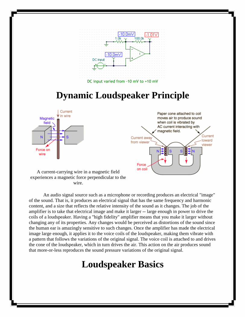
DC input varied from -10 mV to +10 mV
Dynamic Loudspeaker Principle
A current-carrying wire in a magnetic field
experiences a magnetic force perpendicular to the
wire.
An audio signal source such as a microphone or recording produces an electrical "image"
of the sound. That is, it produces an electrical signal that has the same frequency and harmonic
content, and a size that reflects the relative intensity of the sound as it changes. The job of the
amplifier is to take that electrical image and make it larger -- large enough in power to drive the
coils of a loudspeaker. Having a "high fidelity" amplifier means that you make it larger without
changing any of its properties. Any changes would be perceived as distortions of the sound since
the human ear is amazingly sensitive to such changes. Once the amplifier has made the electrical
image large enough, it applies it to the voice coils of the loudspeaker, making them vibrate with
a pattern that follows the variations of the original signal. The voice coil is attached to and drives
the cone of the loudspeaker, which in turn drives the air. This action on the air produces sound
that more-or-less reproduces the sound pressure variations of the original signal.
Loudspeaker Basics

The loudspeakers are almost always the limiting element on the
fidelity of a reproduced sound in either home or theater. The
other stages in sound reproduction are mostly electronic, and the
electronic components are highly developed. The loudspeaker
involves electromechanical processes where the amplified audio
signal must move a cone or other mechanical device to produce
sound like the original sound wave. This process involves many
difficulties, and usually is the most imperfect of the steps in
sound reproduction. Choose your speakers carefully. Some basic
ideas about speaker enclosures might help with perspective.
Once you have chosen a good loudspeaker from a reputable
manufacturer and paid a good price for it, you might presume that
you would get good sound reproduction from it. But you won't ---
not without a good enclosure. The enclosure is an essential part of
sound production because of the following problems with a direct
radiating loudspeaker:
Click image for more
details.
The sound from the back of the speaker cone will
tend to cancel the sound from the front, especially
for low frequencies.
The free cone speaker is very inefficient at
producing sound wavelengths longer than the
diameter of the speaker.
Speakers have a free-cone resonant frequency which
distorts the sound by responding too strongly to
frequencies near resonance.
More power is needed in the bass range, making
multiple drivers with a crossover a practical
necessity for good sound.
Loudspeaker system design:
Crossover:
A passive crossover.

Bi-amped.
Used in multi-driver speaker systems, the crossover is a subsystem that separates the
input signal into different frequency ranges suited to each driver. The drivers receive only the
power in their usable frequency range (the range they were designed for), thereby reducing
distortion in the drivers and interference between them.
Crossovers can be passive or active. A passive crossover is an electronic circuit that uses
a combination of one or more resistors, inductors, or non-polar capacitors. These parts are
formed into carefully designed networks and are most often placed between the power amplifier
and the loudspeaker drivers to divide the amplifier's signal into the necessary frequency bands
before being delivered to the individual drivers. Passive crossover circuits need no external
power beyond the audio signal itself, but do cause overall signal loss and a significant reduction
in damping factor between the voice coil and the crossover. An active crossover is an electronic
filter circuit that divides the signal into individual frequency bands before power amplification,
thus requiring at least one power amplifier for each bandpass.Passive filtering may also be used
in this way before power amplification, but it is an uncommon solution, due to inflexibility
compared to active filtering. Any technique that uses crossover filtering followed by
amplification is commonly known as bi-amping, tri-amping, quad-amping, and so on, depending
on the minimum number of amplifier channels.Some loudspeaker designs use a combination of
passive and active crossover filtering, such as a passive crossover between the mid- and high-
frequency drivers and an active
Crossovers, like the driver units that they feed, have power handling limits, have insertion
losses (10% is often claimed), and change the load seen by the amplifier. The changes are
matters of concern for many in the hi-fi world.When high output levels are required, active
crossovers may be preferable. Active crossovers may be simple circuits that emulate the response
of a passive network, or may be more complex, allowing extensive audio adjustments. Some
active crossovers, usually digital loudspeaker management systems, may include facilities for
precise alignment of phase and time between frequency bands, equalization, and dynamics
(compression and limiting) control.
Some hi-fi and professional loudspeaker systems now include an active crossover circuit
as part of an onboard amplifier system. These speaker designs are identifiable by their need for
AC power in addition to a signal cable from a pre-amplifier. This active topology may include
driver protection circuits and other features of a digital loudspeaker management system.
Powered speaker systems are common in computer sound (for a single listener) and, at the other

end of the size spectrum, in modern concert sound systems, where their presence is significant
and steadily increasing.
Musical Instrument Digital Interface:
MIDI (Musical Instrument Digital Interface), is an industry-standard protocol that enables
electronic musical instruments (synthesizers, drum machines), computers and other electronic
equipment (MIDI controllers, sound cards, samplers) to communicate and synchronize with each
other. Unlike analog devices, MIDI does not transmit an audio signal — it sends event messages
about pitch and intensity, control signals for parameters such as volume, vibrato and panning,
cues, and clock signals to set the tempo. As an electronic protocol, it is notable for its widespread
adoption throughout the music industry. MIDI protocol was defined in 1982.
Note names and MIDI note numbers.
All MIDI-compatible controllers, musical instruments, and MIDI-compatible software
follow the same MIDI 1.0 specification, and thus interpret any given MIDI message the same
way, and so can communicate with and understand each other. MIDI composition and
arrangement takes advantage of MIDI 1.0 and General MIDI (GM) technology to allow musical
data files to be shared among many different devices due to some incompatibility with various
electronic instruments by using a standard, portable set of commands and parameters. Because
the music is stored as instructions rather than recorded audio waveforms, the data size of the files
is quite small by comparison. Individual MIDI files can be traced through their own individual

key code.This key code was established in early 1994 to combat piracy within the sharing of
.mid files.
MIDI Messages:
The MIDI Message specification (or "MIDI Protocol") is probably the most important part of
MIDI.
Though originally intended just for use over MIDI Cables to connect two keyboards,
MIDI messages are now used inside computers and cell phones to generate music, and
transported over any number of professional and consumer interfaces (USB, FireWire, etc.) to a
wide variety of MIDI-equipped devices. There are different message groups for different
applications, only some of which are we able to explain here.
MIDI is a music description language in digital (binary) form. It was designed for use
with keyboard-based musical instruments, so the message structure is oriented to performance
events, such as picking a note and then striking it, or setting typical parameters available on
electronic keyboards. For example, to sound a note in MIDI you send a "Note On" message, and
then assign that note a "velocity", which determines how loud it plays relative to other notes.
You can also adjust the overall loudness of all the notes with a Channel Volume" message. Other
MIDI messages include selecting which instrument sounds to use, stereo panning, and more.
The first specification (1983) did not define every possible "word" that can be spoken in
MIDI , nor did it define every musical instruction that might be desired in an electronic
performance. So over the past 20 or more years, companies have enhanced the original MIDI
specification by defining additional performance control messages, and creating companion
specifications which include:
MIDI Machine Control MIDI Show Control MIDI Time Code General MIDI Downloadable Sounds Scalable Polyphony MIDI
Alternate Applications MIDI Machine Control and MIDI Show Control are interesting
extensions because instead of addressing musical instruments they address studio recording
equipment (tape decks etc) and theatrical control (lights, smoke machines, etc.).
MIDI is also being used for control of devices where standard messages have not been
defined by MMA, such as with audio mixing console automation.
Tables displaying some of the most commonly used messages for musical performance are
available below and via the links in the left-hand column.. For the complete specification(s), you
will need to get the most recent edition of the Complete MIDI 1.0 Detailed Specification and any
supplemental documents and/or specifications that are appropriate.

Table 1 - Summary of MIDI Messages
The following table lists many of the major MIDI messages in numerical (binary) order.
This table is intended as an overview of MIDI, and is by no means complete. Additional
messages are listed in the printed documentation available from the MMA.
Table 1: MIDI 1.0 Specification Message Summary
Status
D7----D0
Data Byte(s)
D7----D0
Description
Channel Voice Messages [nnnn = 0-15 (MIDI Channel Number 1-16)]
1000nnnn 0kkkkkkk
0vvvvvvv
Note Off event.
This message is sent when a note is released (ended).
(kkkkkkk) is the key (note) number. (vvvvvvv) is the velocity.
1001nnnn 0kkkkkkk
0vvvvvvv
Note On event.
This message is sent when a note is depressed (start).
(kkkkkkk) is the key (note) number. (vvvvvvv) is the velocity.
1010nnnn 0kkkkkkk
0vvvvvvv
Polyphonic Key Pressure (Aftertouch).
This message is most often sent by pressing down on the key
after it "bottoms out". (kkkkkkk) is the key (note) number.
(vvvvvvv) is the pressure value.
1011nnnn 0ccccccc
0vvvvvvv
Control Change.
This message is sent when a controller value changes.
Controllers include devices such as pedals and levers.
Controller numbers 120-127 are reserved as "Channel Mode
Messages" (below). (ccccccc) is the controller number (0-
119). (vvvvvvv) is the controller value (0-127).
1100nnnn 0ppppppp Program Change. This message sent when the patch number
changes. (ppppppp) is the new program number.
1101nnnn 0vvvvvvv Channel Pressure (After-touch). This message is most often

sent by pressing down on the key after it "bottoms out". This
message is different from polyphonic after-touch. Use this
message to send the single greatest pressure value (of all the
current depressed keys). (vvvvvvv) is the pressure value.
1110nnnn 0lllllll
0mmmmmmm
Pitch Wheel Change. 0mmmmmmm This message is sent to
indicate a change in the pitch wheel. The pitch wheel is
measured by a fourteen bit value. Center (no pitch change) is
2000H. Sensitivity is a function of the transmitter. (llllll) are
the least significant 7 bits. (mmmmmm) are the most
significant 7 bits.
Channel Mode Messages (See also Control Change, above)
1011nnnn 0ccccccc
0vvvvvvv
Channel Mode Messages.
This the same code as the Control Change (above), but
implements Mode control and special message by using
reserved controller numbers 120-127. The commands are:
All Sound Off. When All Sound Off is received all oscillators
will turn off, and their volume envelopes are set to zero as
soon as possible. c = 120, v = 0: All Sound Off
Reset All Controllers. When Reset All Controllers is received,
all controller values are reset to their default values. (See
specific Recommended Practices for defaults).
c = 121, v = x: Value must only be zero unless otherwise
allowed in a specific Recommended Practice.
Local Control. When Local Control is Off, all devices on a
given channel will respond only to data received over MIDI.
Played data, etc. will be ignored. Local Control On restores
the functions of the normal controllers.
c = 122, v = 0: Local Control Off
c = 122, v = 127: Local Control On
All Notes Off. When an All Notes Off is received, all
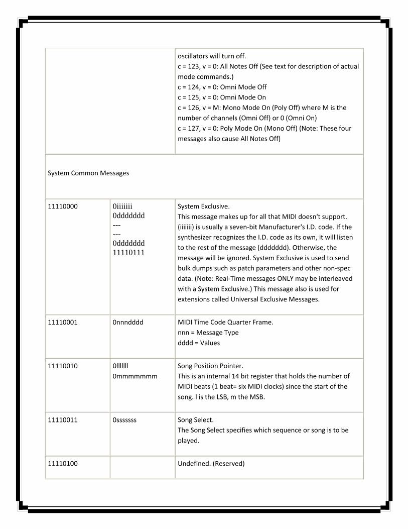
oscillators will turn off.
c = 123, v = 0: All Notes Off (See text for description of actual
mode commands.)
c = 124, v = 0: Omni Mode Off
c = 125, v = 0: Omni Mode On
c = 126, v = M: Mono Mode On (Poly Off) where M is the
number of channels (Omni Off) or 0 (Omni On)
c = 127, v = 0: Poly Mode On (Mono Off) (Note: These four
messages also cause All Notes Off)
System Common Messages
11110000 0iiiiiii
0ddddddd
---
---
0ddddddd
11110111
System Exclusive.
This message makes up for all that MIDI doesn't support.
(iiiiiii) is usually a seven-bit Manufacturer's I.D. code. If the
synthesizer recognizes the I.D. code as its own, it will listen
to the rest of the message (ddddddd). Otherwise, the
message will be ignored. System Exclusive is used to send
bulk dumps such as patch parameters and other non-spec
data. (Note: Real-Time messages ONLY may be interleaved
with a System Exclusive.) This message also is used for
extensions called Universal Exclusive Messages.
11110001 0nnndddd MIDI Time Code Quarter Frame.
nnn = Message Type
dddd = Values
11110010 0lllllll
0mmmmmmm
Song Position Pointer.
This is an internal 14 bit register that holds the number of
MIDI beats (1 beat= six MIDI clocks) since the start of the
song. l is the LSB, m the MSB.
11110011 0sssssss Song Select.
The Song Select specifies which sequence or song is to be
played.
11110100 Undefined. (Reserved)

11110101 Undefined. (Reserved)
11110110 Tune Request. Upon receiving a Tune Request, all analog
synthesizers should tune their oscillators.
11110111 End of Exclusive. Used to terminate a System Exclusive dump
(see above).
System Real-Time Messages
11111000 Timing Clock. Sent 24 times per quarter note when
synchronization is required (see text).
11111001 Undefined. (Reserved)
11111010 Start. Start the current sequence playing. (This message will
be followed with Timing Clocks).
11111011 Continue. Continue at the point the sequence was Stopped.
11111100 Stop. Stop the current sequence.
11111101 Undefined. (Reserved)
11111110 Active Sensing. Use of this message is optional. When
initially sent, the receiver will expect to receive another
Active Sensing message each 300ms (max), or it will be
assume that the connection has been terminated. At
termination, the receiver will turn off all voices and return to
normal (non- active sensing) operation.
11111111 Reset. Reset all receivers in the system to power-up status.
This should be used sparingly, preferably under manual
control. In particular, it should not be sent on power-up.

MIDI Cables & Connectors:
Many different "transports" can be used for MIDI messages. The speed of the transport
determines how much MIDI data can be carried, and how quickly it will be received.
Each transport has its own performance characteristics which might make some difference in
specific applications, but in general the transport is the least important part of MIDI , as long as it allows
you to connect all the devices you want use!
5-Pin MIDI DIN
Using a 5-pin "DIN" connector, the MIDI DIN transport was developed back in 1983, so it is slow
compared to common high-speed digital transports available today, like USB, FireWire, and Ethernet.
But MIDI-DIN is almost always still used on most MIDI-equipped devices because it adequately handles
communication speed for one device. IF you want to connect one MIDI device to another (not a
computer), MIDI cables are still the best way to go.
It used to be that connecting a MIDI device to a computer meant installing a "sound card" or
"MIDI interface" in order to have a MIDI DIN connector on the computer. Because of space limitations,
most such cards did not have actual 5-Pin DIN connectors on the card, but provided a special cable with
5-Pin DINs (In and Out) on one end (often connected to the "joystick port"). All such cards need "driver"
software to make the MIDI connection work, but there are a few standards that companies follow,
including "MPU-401" and "SoundBlaster". Even with those standards, however, making MIDI work could
be a major task.
Over a number of years the components of the typical sound card and MIDI interface (including
the joystick port) became standard on the motherboard of most PCs, but this did not make configuring
them any easier.
Serial, Parallel, and Joystick Ports
Before USB and FireWire, personal computers were all generally equipped with serial, parallel,
and (possibly) joystick ports, all of which have been used for connecting MIDI-equipped instruments
(through special adapters). Though not always faster than MIDI-DIN, these connectors were already
available on computers and that made them an economical alternative to add-on cards, with the added
benefit that in general they already worked and did not need special configuration.
The High Speed Serial Ports such as the "mini-DIN" ports available on early Macintosh
computers support communication speeds roughly 20 times faster than MIDI-DIN, making it also
possible for companies to develop and market "multiport" MIDI interfaces that allowed connecting
multiple MIDI-DINs to one computer. In this manner it became possible to have the computer address
many different MIDI-equipped devices at the same time. Recent multi-port MIDI interfaces use even
faster USB or FireWire ports to connect to the computer.
USB and FireWire
All recent computers are equipped with either USB and/or FireWire connectors, and these are
now the most common means of connecting MIDI devices to computers (using appropriate format
adapters). Adapters can be as simple as a short cable with USB on one end and MIDI DIN on the other,
or as complex as a 19 inch rack mountable CPU with dozens of MIDI and Audio In and Out ports. The
best part is that USB and FireWire are "plug-and-play" interfaces which means they generally configure
themselves. In most cases, all you need to do is plug in your USB or FireWire MIDI interface and boot up
some MIDI software and off you go.
Current USB technology generally supports communication between a host (PC) and a device, so
it is not possible to connect to USB devices to each other as it is with two MIDI DIN devices. (This may
change sometime in the future with new versions of USB). Since communications all go through the PC,
any two USB MIDI devices can use different schemes for packing up MIDI messages and sending them
over USB... the USB device's driver on the host knows how that device does it, and will convert the MIDI
messages from USB back to MIDI at the host. That way all USB MIDI devices can talk to each other
(through the host) without needing to follow one specification for how they send MIDI data over USB.
Most FireWire MIDI devices also connect directly to a PC with a host device driver and so can
talk to other FireWire MIDI devices even if they use a proprietary method for formatting their MIDI data.
But FireWire supports "peer-to-peer" connections, so MMA has produced a specification for MIDI over
IEEE-1394 (FireWire), which is available for download on this site (and incorporated in IEC-61883 part
5).
Ethernet
If you are connecting a number of MIDI instruments to one or more computers, using Ethernet
seems like a great solution. In the MIDI industry there is not yet agreement on the market desire for
MIDI over Ethernet, nor on the net value of the benefits vs. challenges of using Ethernet, and so there is
currently no MMA standard for MIDI over Ethernet.
However, other Standard Setting Organizations have specifications for MIDI Over Ethernet, and we
think it appropriate that people know about those solutions. There are also proprietary solutions for
MIDI Over Ethernet, but because they are not open standards they are not appropriate for discussion by
MMA.
IETF RTP-MIDI
The IETF RTP Payload Format for MIDI solution has received extensive modification in response to
comments by MMA-members, and is also the foundation of Apple's own MIDI Over Ethernet solution.
Though neither solution has been officially adopted or endorsed in any way by MMA, both technologies
have stood up to MMA member scrutiny and so are likely to appear (in one manner or another) in future
MIDI hardware and/or software products.
IEEE Ethernet AVB
For the past several years, the IEEE has been developing protocols for low-latency audio and video
transport over Ethernet with high quality of service. These protocols are known as Audio/Video Bridging,
or AVB, and are part of the larger IEEE 802.1 Working Group, which develops networking standards that
enable interoperability of such ubiquitous devices as Ethernet switches. The AVB protocols provide
precision time synchronization and stream bandwidth reservation at the network level.
The AVB protocols do not provide a standard means for interoperable communication of content
such as a live video stream. Utilizing the 802.1 AVB protocols, the IEEE P1722 AVB Transport Protocol
(AVBTP) draft standard provides the necessary content encapsulation in an evolutionary manner by
adopting the existing IEEE 1394 (Firewire) audio and video streaming mechanisms already in use by
millions of devices. However, AVBTP is not limited to bridging IEEE 1394 content, as it provides
extensibility to encapsulate new and different media formats.
The MMA collaborated with the IEEE P1722 working group to enable transport of MIDI and any
future content format defined by the MMA over IEEE P1722 networks. The P1722 standard defines MIDI
1.0 content within this protocol by referencing an MMA-authored document. The MMA has not yet
published that document, but plans to do so in the near future.
Basic MIDI Connections:
Let's first take a look at what you need to get your MIDI (Recording) system setup:
Hardware:
Computer - either PC or laptop. MIDI keyboard or USB keyboard with or without sounds. Soundcard either fitted inside your computer or external soundcard. USB or MIDI cable(s).
Software
Install drivers for soundcard (better to download latest version from manufacturer). SEARCH TIP: Go to Google and search "Model number of card + drivers download". i.e. If your soundcard is called "SoundcardXYZ" then type "SoundcardXYZ drivers download" (without the quotes) into
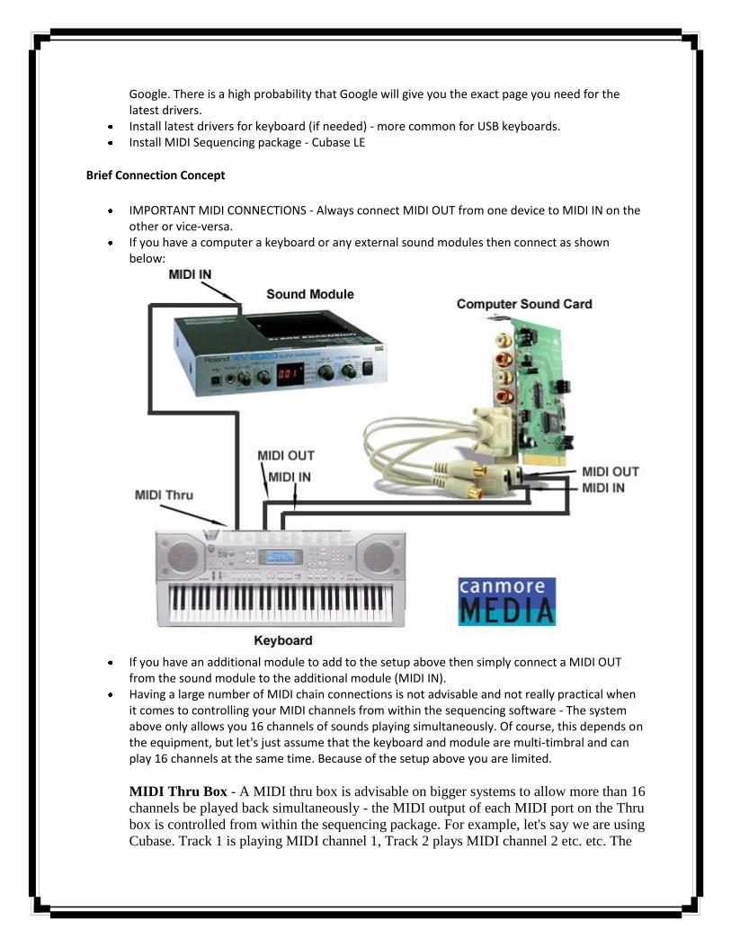
Google. There is a high probability that Google will give you the exact page you need for the latest drivers.
Install latest drivers for keyboard (if needed) - more common for USB keyboards. Install MIDI Sequencing package - Cubase LE
Brief Connection Concept
IMPORTANT MIDI CONNECTIONS - Always connect MIDI OUT from one device to MIDI IN on the other or vice-versa.
If you have a computer a keyboard or any external sound modules then connect as shown below:
If you have an additional module to add to the setup above then simply connect a MIDI OUT
from the sound module to the additional module (MIDI IN). Having a large number of MIDI chain connections is not advisable and not really practical when
it comes to controlling your MIDI channels from within the sequencing software - The system above only allows you 16 channels of sounds playing simultaneously. Of course, this depends on the equipment, but let's just assume that the keyboard and module are multi-timbral and can play 16 channels at the same time. Because of the setup above you are limited.
MIDI Thru Box - A MIDI thru box is advisable on bigger systems to allow more than 16
channels be played back simultaneously - the MIDI output of each MIDI port on the Thru
box is controlled from within the sequencing package. For example, let's say we are using
Cubase. Track 1 is playing MIDI channel 1, Track 2 plays MIDI channel 2 etc. etc. The
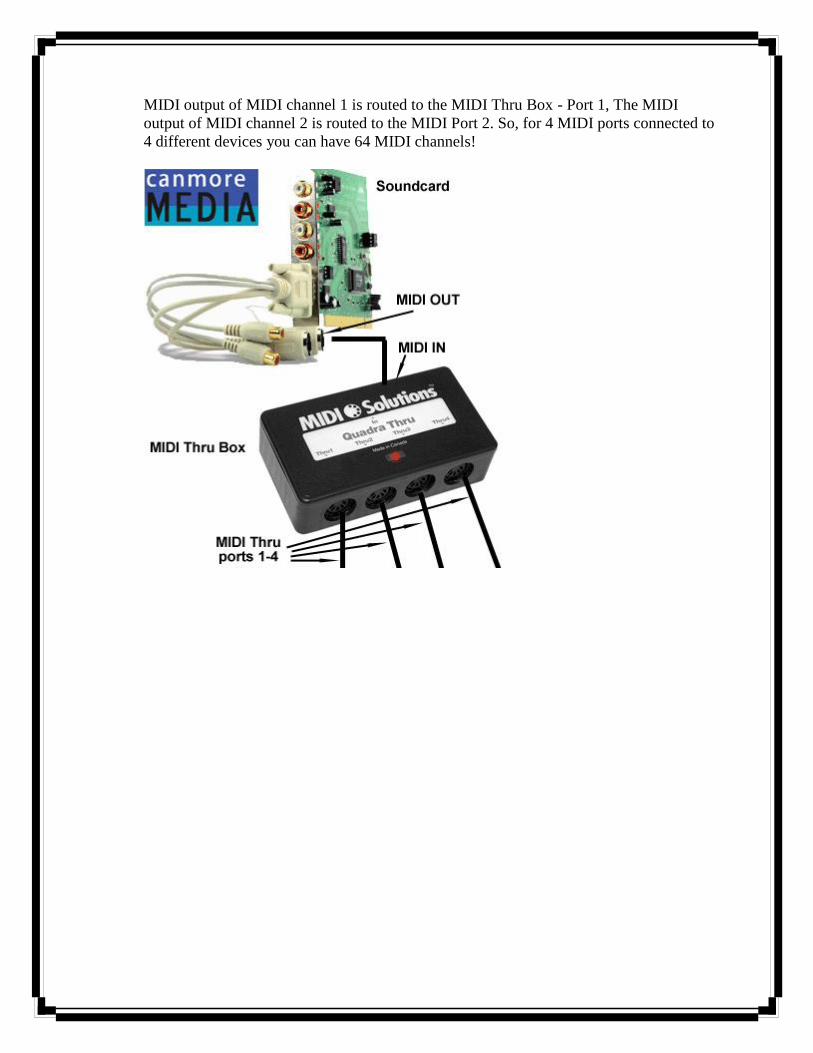
MIDI output of MIDI channel 1 is routed to the MIDI Thru Box - Port 1, The MIDI
output of MIDI channel 2 is routed to the MIDI Port 2. So, for 4 MIDI ports connected to
4 different devices you can have 64 MIDI channels!
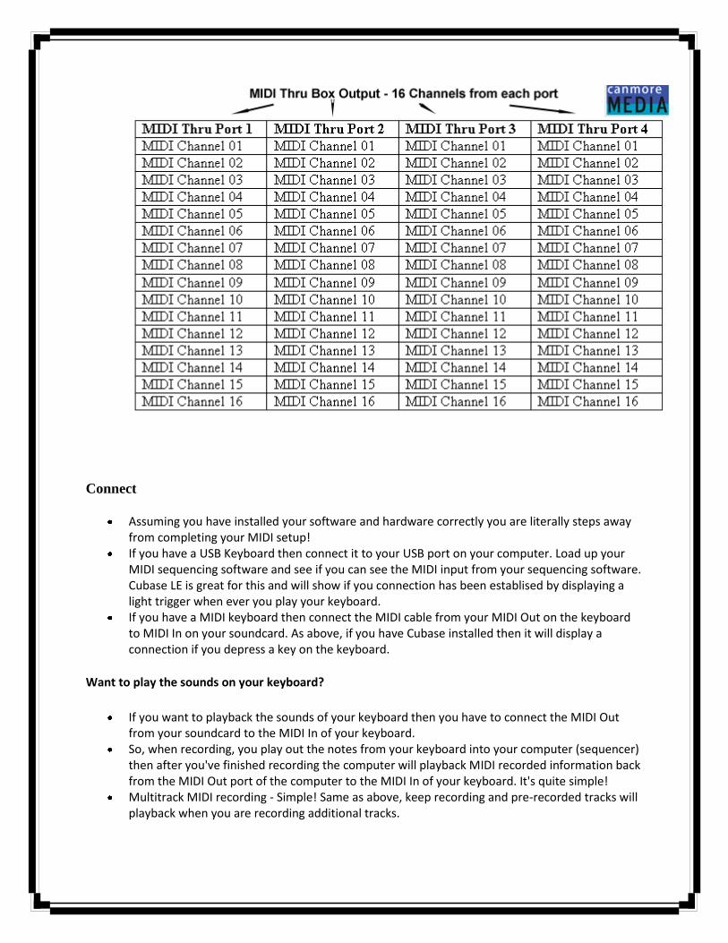
Connect
Assuming you have installed your software and hardware correctly you are literally steps away from completing your MIDI setup!
If you have a USB Keyboard then connect it to your USB port on your computer. Load up your MIDI sequencing software and see if you can see the MIDI input from your sequencing software. Cubase LE is great for this and will show if you connection has been establised by displaying a light trigger when ever you play your keyboard.
If you have a MIDI keyboard then connect the MIDI cable from your MIDI Out on the keyboard to MIDI In on your soundcard. As above, if you have Cubase installed then it will display a connection if you depress a key on the keyboard.
Want to play the sounds on your keyboard?
If you want to playback the sounds of your keyboard then you have to connect the MIDI Out from your soundcard to the MIDI In of your keyboard.
So, when recording, you play out the notes from your keyboard into your computer (sequencer) then after you've finished recording the computer will playback MIDI recorded information back from the MIDI Out port of the computer to the MIDI In of your keyboard. It's quite simple!
Multitrack MIDI recording - Simple! Same as above, keep recording and pre-recorded tracks will playback when you are recording additional tracks.
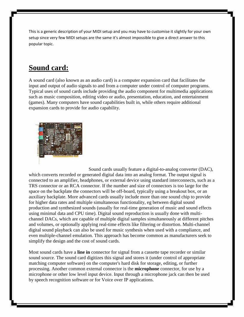
This is a generic description of your MIDI setup and you may have to customise it slightly for your own
setup since very few MIDI setups are the same it's almost impossible to give a direct answer to this
popular topic.
Sound card:
A sound card (also known as an audio card) is a computer expansion card that facilitates the
input and output of audio signals to and from a computer under control of computer programs.
Typical uses of sound cards include providing the audio component for multimedia applications
such as music composition, editing video or audio, presentation, education, and entertainment
(games). Many computers have sound capabilities built in, while others require additional
expansion cards to provide for audio capability.
Sound cards usually feature a digital-to-analog converter (DAC),
which converts recorded or generated digital data into an analog format. The output signal is
connected to an amplifier, headphones, or external device using standard interconnects, such as a
TRS connector or an RCA connector. If the number and size of connectors is too large for the
space on the backplate the connectors will be off-board, typically using a breakout box, or an
auxiliary backplate. More advanced cards usually include more than one sound chip to provide
for higher data rates and multiple simultaneous functionality, eg between digital sound
production and synthesized sounds (usually for real-time generation of music and sound effects
using minimal data and CPU time). Digital sound reproduction is usually done with multi-
channel DACs, which are capable of multiple digital samples simultaneously at different pitches
and volumes, or optionally applying real-time effects like filtering or distortion. Multi-channel
digital sound playback can also be used for music synthesis when used with a compliance, and
even multiple-channel emulation. This approach has become common as manufacturers seek to
simplify the design and the cost of sound cards.
Most sound cards have a line in connector for signal from a cassette tape recorder or similar
sound source. The sound card digitizes this signal and stores it (under control of appropriate
matching computer software) on the computer's hard disk for storage, editing, or further
processing. Another common external connector is the microphone connector, for use by a
microphone or other low level input device. Input through a microphone jack can then be used
by speech recognition software or for Voice over IP applications.
Audio file format:
An audio file format is a file format for storing audio data on a computer system. It can be a raw
bitstream, but it is usually a container format or an audio data format with defined storage layer.
The general approach towards storing digital audio is to sample the audio voltage which, on
playback, would correspond to a certain level of signal in an individual channel with a certain
resolution—the number of bits per sample—in regular intervals (forming the sample rate). This
data can then be stored uncompressed, or compressed to reduce the file size
Types of formats:
It is important to distinguish between a file format and a CODEC. A codec performs the
encoding and decoding of the raw audio data while the data itself is stored in a file with a
specific audio file format. Most of the publicly documented audio file formats can be created
with one of two or more encoders or codecs. Although most audio file formats support only one
type of audio data (created with an audio coder), a multimedia container format (as MKV or
AVI) may support multiple types of audio and video data.
There are three major groups of audio file formats:
Uncompressed audio formats, such as WAV, AIFF, AU or raw header-less PCM; formats with lossless compression, such as FLAC, Monkey's Audio (filename extension APE),
WavPack (filename extension WV), Shorten, TTA, ATRAC Advanced Lossless, Apple Lossless, MPEG-4 SLS, MPEG-4 ALS, MPEG-4 DST, Windows Media Audio Lossless (WMA Lossless).
formats with lossy compression, such as MP3, Vorbis, Musepack, AAC, ATRAC and lossy Windows Media Audio (WMA).
Uncompressed audio formats
There is one major uncompressed audio format, PCM which is usually stored as a .wav on
Windows or as .aiff on Mac OS. WAV and AIFF are flexible file formats designed to store more
or less any combination of sampling rates or bitrates. This makes them suitable file formats for
storing and archiving an original recording. There is another uncompressed audio format which
is .cda (Audio CD Track) .cda is from a music CD and is 0% compressed.
The AIFF format is based on the IFF format. The WAV format is based on the RIFF file format,
which is similar to the IFF format.
BWF (Broadcast Wave Format) is a standard audio format created by the European Broadcasting
Union as a successor to WAV. BWF allows metadata to be stored in the file. See European
Broadcasting Union: Specification of the Broadcast Wave Format (EBU Technical document
3285, July 1997). This is the primary recording format used in many professional audio
workstations in the television and film industry. BWF files include a standardized Timestamp
reference which allows for easy synchronization with a separate picture element. Stand-alone,
file based, multi-track recorders from Sound Devices, Zaxcom, HHB USA, Fostex, and Aaton all
use BWF as their preferred format.
Lossless compressed audio formats
A lossless compressed format requires much more processing time than an uncompressed format
but is more efficient in space usage.
Uncompressed audio formats encode both sound and silence with the same number of bits per
unit of time. Encoding an uncompressed minute of absolute silence produces a file of the same
size as encoding an uncompressed minute of symphonic orchestra music. In a lossless
compressed format, however, the music would occupy a marginally smaller file and the silence
take up almost no space at all.
Lossless compression formats (such as the most widespread FLAC, WavPack. Monkey's Audio,
ALAC/Apple Lossless) provide a compression ratio of about 2:1. Development in lossless
compression formats aims to reduce processing time while maintaining a good compression
ratio.
Free and open file formats
wav – standard audio file container format used mainly in Windows PCs. Commonly used for storing uncompressed (PCM) , CD-quality sound files, which means that they can be large in size—around 10 MB per minute. Wave files can also contain data encoded with a variety of (lossy) codecs to reduce the file size (for example the GSM or mp3 codecs). Wav files use a RIFF structure.
ogg – a free, open source container format supporting a variety of codecs, the most popular of which is the audio codec Vorbis. Vorbis offers compression similar to MP3 but is less popular.
mpc - Musepack or MPC (formerly known as MPEGplus, MPEG+ or MP+) is an open source lossy audio codec, specifically optimized for transparent compression of stereo audio at bitrates of 160–180 kbit/s.
flac – Free Lossless Audio Codec, a lossless compression codec. aiff – standard audio file format used by Apple. It could be considered the Apple equivalent of
wav. raw – a raw file can contain audio in any codec but is usually used with PCM audio data. It is
rarely used except for technical tests. au – the standard audio file format used by Sun, Unix and Java. The audio in au files can be PCM
or compressed with the μ-law, a-law or G729 codecs.
Open file formats
gsm – designed for telephony use in Europe, gsm is a very practical format for telephone quality voice. It makes a good compromise between file size and quality. Note that wav files can also be encoded with the gsm codec.
dct – A variable codec format designed for dictation. It has dictation header information and can be encrypted (often required by medical confidentiality laws).
vox – the vox format most commonly uses the Dialogic ADPCM (Adaptive Differential Pulse Code Modulation) codec. Similar to other ADPCM formats, it compresses to 4-bits. Vox format files are similar to wave files except that the vox files contain no information about the file itself so the codec sample rate and number of channels must first be specified in order to play a vox file.
mmf - a Samsung audio format that is used in ringtones.
Proprietary formats
mp3 – MPEG Layer-3 format is the most popular format for downloading and storing music. By eliminating portions of the audio file that are less audible, mp3 files are compressed to roughly one-tenth the size of an equivalent PCM file sacrificing quality.
aac – the Advanced Audio Coding format is based on the MPEG2 and MPEG4 standards. aac files are usually ADTS or ADIF containers.
mp4/m4a – MPEG-4 audio most often AAC but sometimes MP2/MP3, MPEG-4 SLS, CELP, HVXC and other audio object types defined in MPEG-4 Audio
wma – the popular Windows Media Audio format owned by Microsoft. Designed with Digital Rights Management (DRM) abilities for copy protection.
atrac (.wav) – the older style Sony ATRAC format. It always has a .wav file extension. To open these files simply install the ATRAC3 drivers.
ra & rm – a Real Audio format designed for streaming audio over the Internet. The .ra format allows files to be stored in a self-contained fashion on a computer, with all of the audio data contained inside the file itself.
ram – a text file that contains a link to the Internet address where the Real Audio file is stored. The .ram file contains no audio data itself.
dss – Digital Speech Standard files are an Olympus proprietary format. It is a fairly old and poor codec. Gsm or mp3 are generally preferred where the recorder allows. It allows additional data to be held in the file header.
msv – a Sony proprietary format for Memory Stick compressed voice files. dvf – a Sony proprietary format for compressed voice files; commonly used by Sony dictation
recorders. IVS – A proprietary version with Digital Rights Management developed by 3D Solar UK Ltd for
use in music downloaded from their Tronme Music Store and interactive music and video player. m4p – A proprietary version of AAC in MP4 with Digital Rights Management developed by Apple
for use in music downloaded from their iTunes Music Store. iklax – An iKlax Media proprietary format, the iKlax format is a multi-track digital audio format
allowing various actions on musical data, for instance on mixing and volumes arrangements. mxp4 – a Musinaut proprietary format allowing play of different versions (or skins) of the same
song. It allows various interactivity scenarios between the artist and the end user. 3gp - multimedia container format can contain proprietary formats as AMR, AMR-WB or AMR-
WB+, but also some open formats amr - AMR-NB audio, used primarily for speech awb - AMR-WB audio, used primarily for speech
Codec:
A codec is a device or computer program capable of encoding and/or decoding a digital
data stream or signal. The word codec is a portmanteau of 'compressor-decompressor' or, more

commonly, 'coder-decoder'. A codec (the program) should not be confused with a coding or
compression format or standard – a format is a document (the standard), a way of storing data,
while a codec is a program (an implementation) which can read or write such files. In practice
"codec" is sometimes used loosely to refer to formats, however.
A codec encodes a data stream or signal for transmission, storage or encryption, or
decodes it for playback or editing. Codecs are used in videoconferencing, streaming media and
video editing applications. A video camera's analog-to-digital converter (ADC) converts its
analog signals into digital signals, which are then passed through a video compressor for digital
transmission or storage. A receiving device then runs the signal through a video decompressor,
then a digital-to-analog converter (DAC) for analog display. The term codec is also used as a
generic name for a video conferencing unit.
Media codecs:
Codecs are often designed to emphasize certain aspects of the media, or their use, to be
encoded. For example, a digital video (using a DV codec) of a sports event needs to encode
motion well but not necessarily exact colors, while a video of an art exhibit needs to perform
well encoding color and surface texture.
Audio codecs for cell phones need to have very low latency between source encoding and
playback; while audio codecs for recording or broadcast can use high-latency audio compression
techniques to achieve higher fidelity at a lower bit-rate.
There are thousands of audio and video codecs ranging in cost from free to hundreds of
dollars or more. This variety of codecs can create compatibility and obsolescence issues. By
contrast, raw uncompressed PCM audio (44.1 kHz, 16 bit stereo, as represented on an audio CD
or in a .wav or .aiff file) is a standard across multiple platforms.
Many multimedia data streams contain both audio and video, and often some metadata
that permit synchronization of audio and video. Each of these three streams may be handled by
different programs, processes, or hardware; but for the multimedia data streams to be useful in
stored or transmitted form, they must be encapsulated together in a container format.
Lower bit rate codecs allow more users, but they also have more distortion. Beyond the
initial increase in distortion, lower bit rate codecs also achieve their lower bit rates by using more
complex algorithms that make certain assumptions, such as those about the media and the packet
loss rate. Other codecs may not make those same assumptions. When a user with a low bit-rate
codec talks to a user with another codec, additional distortion is introduced by each transcoding.
The notion of AVI being a codec is incorrect as AVI is a container format, which many
codecs might use (although not to ISO standard). There are also other well-known containers
such as Ogg, ASF, QuickTime, RealMedia, Matroska, DivX Media Format and containers
defined as ISO standards, such as MPEG transport stream, MPEG program stream, MP4 and ISO
base media file format.
Audio player (software):
An audio player is a kind of media player for playing back digital audio, including
optical discs such as CDs, SACDs, DVD-Audio, HDCD, audio files and streaming audio.
In addition to VCR-like functions like playing, pausing, stopping, rewinding, and
forwarding, some common functions include playlisting, tagging format support, and equalizer.
Many of the audio players also support simple playback of digital videos in which we can
also run movies.
Digital audio player:
Digital audio player, shortened to DAP, MP3 player or, rarely, as an OGG player, is a
consumer electronic device that stores, organizes and plays digital audio files. In contrast,
analog audio players play music from cassette tapes, or records. Portable devices that also
play video and text are referred to as portable media players.
Sound recording and reproduction:
Sound recording and reproduction is an electrical or mechanical inscription and re-
creation of sound waves, such as spoken voice, singing, instrumental music, or sound effects.
The two main classes of sound recording technology are analog recording and digital recording.
Acoustic analog recording is achieved by a small microphone diaphragm that can detect changes
in atmospheric pressure (acoustic sound waves) and record them as a graphic representation of
the sound waves on a medium such as a phonograph (in which a stylus senses grooves on a
record). In magnetic tape recording, the sound waves vibrate the microphone diaphragm and are
converted into a varying electric current, which is then converted to a varying magnetic field by
an electromagnet, which makes a representation of the sound as magnetized areas on a plastic
tape with a magnetic coating on it. Analog sound reproduction is the reverse process, with a
bigger loudspeaker diaphragm causing changes to atmospheric pressure to form acoustic sound
waves. Electronically generated sound waves may also be recorded directly from devices such as
an electric guitar pickup or a synthesizer, without the use of acoustics in the recording process
other than the need for musicians to hear how well they are playing during recording sessions.
Digital recording and reproduction converts the analog sound signal picked up by the
microphone to a digital form by a process of digitization, allowing it to be stored and transmitted
by a wider variety of media. Digital recording stores audio as a series of binary numbers
representing samples of the amplitude of the audio signal at equal time intervals, at a sample rate
so fast that the human ear perceives the result as continuous sound. Digital recordings are
considered higher quality than analog recordings not necessarily because they have higher
fidelity (wider frequency response or dynamic range), but because the digital format can prevent
much loss of quality found in analog recording due to noise and electromagnetic interference in
playback, and mechanical deterioration or damage to the storage medium. A digital audio signal
must be reconverted to analog form during playback before it is applied to a loudspeaker or
earphones.
Electrical recording:
Sound recording began as a mechanical process and remained so until the early 1920s
(with the exception of the 1899 Telegraphone) when a string of groundbreaking inventions in the
field of electronics revolutionised sound recording and the young recording industry. These
included sound transducers such as microphones and loudspeakers and various electronic devices
such as the mixing desk, designed for the amplification and modification of electrical sound
signals.
After the Edison phonograph itself, arguably the most significant advances in sound recording,
were the electronic systems invented by two American scientists between 1900 and 1924. In
1906 Lee De Forest invented the "Audion" triode vacuum-tube, electronic valve, which could
greatly amplify weak electrical signals, (one early use was to amplify long distance telephone in
1915) which became the basis of all subsequent electrical sound systems until the invention of
the transistor. The valve was quickly followed by the invention of the Regenerative circuit,
Super-Regenerative circuit and the Superheterodyne receiver circuit, all of which were invented
and patented by the young electronics genius Edwin Armstrong between 1914 and 1922.
Armstrong's inventions made higher fidelity electrical sound recording and reproduction a
practical reality, facilitating the development of the electronic amplifier and many other devices;
after 1925 these systems had become standard in the recording and radio industry.
While Armstrong published studies about the fundamental operation of the triode vacuum
tube before World War I, inventors like Orlando R. Marsh and his Marsh Laboratories, as well as
scientists at Bell Telephone Laboratories, achieved their own understanding about the triode and
were utilizing the Audion as a repeater in weak telephone circuits. By 1925 it was possible to
place a long distance telephone call with these repeaters between New York and San Francisco
in 20 minutes, both parties being clearly heard. With this technical prowess, Joseph P. Maxfield
and Henry C. Harrison from Bell Telephone Laboratories were skilled in using mechanical
analogs of electrical circuits and applied these principles to sound recording and reproduction.
They were ready to demonstrate their results by 1924 using the Wente condenser microphone
and the vacuum tube amplifier to drive the "rubber line" wax recorder to cut a master audio disc.
Meanwhile, radio continued to develop. Armstrong's groundbreaking inventions
(including FM radio) also made possible the broadcasting of long-range, high-quality radio
transmissions of voice and music. The importance of Armstrong's Superheterodyne circuit
cannot be over-estimated — it is the central component of almost all analog amplification and
both analog and digital radio-frequency transmitter and receiver devices to this day
Beginning during World War One, experiments were undertaken in the United States and
Great Britain to reproduce among other things, the sound of a Submarine (u-boat) for training
purposes. The acoustical recordings of that time proved entirely unable to reproduce the sounds,
and other methods were actively sought. Radio had developed independently to this point, and
now Bell Laboritories sought a marriage of the two disparate technologies, greater than the two
separately. The first experiments were not very promising, but by 1920 greater sound fidelity
was achieved using the electrical system than had ever been realized acoustically. One early
recording made without fanfare or announcement was the dedication of the Tomb of the
Unknown Soldier at Arlington Cemetery.
By early 1924 such dramatic progress had been made, that Bell Labs arranged a
demonstration for the leading recording companies, the Victor Talking Machine Company, and
the Columbia Phonograph Co. (Edison was left out due to their decreasing market share and a
stubborn Thomas Edison). Columbia, always in financial straits, could not afford it, and Victor,
essentially leaderless since the mental collapse of founder Eldridge Johnson, left the
demonstration without comment. English Columbia, by then a separate company, got hold of a
test pressing made by Pathé from these sessions, and realized the immediate and urgent need to
have the new system. Bell was only offering its method to United States companies, and to
circumvent this, Managing Director Louis Sterling of English Columbia, bought his once parent
company, and signed up for electrical recording. Although they were contemplating a deal,
Victor Talking Machine was apprised of the new Columbia deal, so they too quickly signed.
Columbia made its first released electrical recordings on February 25, 1925, with Victor
following a few weeks later. The two then agreed privately to "be quiet" until November 1925,
by which time enough electrical repertory would be available.
Other recording formats
In the 1920s, the early talkies featured the new sound-on-film technology which used
photoelectric cells to record and reproduce sound signals that were optically recorded directly
onto the movie film. The introduction of talking movies, spearheaded by The Jazz Singer in 1927
(though it used a sound on disk technique, not a photoelectric one), saw the rapid demise of live
cinema musicians and orchestras. They were replaced with pre-recorded soundtracks, causing the
loss of many jobs.The American Federation of Musicians took out ads in newspapers, protesting
the replacement of real musicians with mechanical playing devices, especially in theatres.
This period also saw several other historic developments including the introduction of the
first practical magnetic sound recording system, the magnetic wire recorder, which was based on
the work of Danish inventor Valdemar Poulsen. Magnetic wire recorders were effective, but the
sound quality was poor, so between the wars they were primarily used for voice recording and
marketed as business dictating machines. In the 1930s radio pioneer Guglielmo Marconi
developed a system of magnetic sound recording using steel tape. This was the same material
used to make razor blades, and not surprisingly the fearsome Marconi-Stille recorders were
considered so dangerous that technicians had to operate them from another room for safety.
Because of the high recording speeds required, they used enormous reels about one metre in
diameter, and the thin tape frequently broke, sending jagged lengths of razor steel flying around
the studio.
Audio and Multimedia
Multimedia content on the Web, by its definition - including or involving the use of
several media - would seem to be inherently accessible or easily made accessible.
However, if the information is audio, such as a RealAudio feed from a news conference
or the proceedings in a courtroom, a person who is deaf or hard of hearing cannot access that
content unless provision is made for a visual presentation of audio content. Similarly, if the
content is pure video, a blind person or a person with severe vision loss will miss the message
without the important information in the video being described.
Remember from Section 2 that to be compliant with Section 508, you must include text
equivalents for all non-text content. Besides including alternative text for images and image map
areas, you need to provide textual equivalents for audio and more generally for multimedia
content.
Some Definitions
A transcript of audio content is a word-for-word textual representation of the audio,
including descriptions of non-text sounds like "laughter" or "thunder." Transcripts of audio
content are valuable not only for persons with disabilities but in addition, they permit searching
and indexing of that content which is not possible with just the audio. "Not possible" is, of
course too strong. Search engines could, if they wanted, employ voice recognition to audio files,
and index that information - but they don't.
When a transcript of the audio part of an audio-visual (multimedia) presentation is
displayed synchronously with the audio-visual presentation, it is called captioning. When
speaking of TV captioning, open captions are those in which the text is always present on the
screen and closed captions are those viewers can choose to display or not.
Descriptive video or described video intersperses explanations of important video with
the normal audio of a multimedia presentation. These descriptions are also called audio
descriptions.
Wave Pad Audio Editing Software:
Professional sound editing software for PC & Mac
This audio editing software is a full featured professional audio and music editor for Windows and Mac
OS X. It lets you record and edit music, voice and other audio recordings. When editing audio files you
can cut, copy and paste parts of recordings then add effects like echo, amplification and noise
reduction. WavePad works as a wav or mp3 editor but it also supports a number of other file formats
including vox, gsm, wma, real audio, au, aif, flac, ogg and more.
Typical Audio Editing Applications

Software audio editing for studios and professional journalists. Edit sound files to broadcast over the internet with the BroadWave Streaming Audio Server Normalizing the level of audio files during mastering before burning to CD. Editing mp3 files for your iPod, PSP or other portable device. As a music editor (includes ringtones creator formats). Music editing and recording to produce mp3 files. Voice editing for multimedia productions (use with our Video Editor). Restoration of audio files including removing excess noise such as hiss and hums.
System Requirements
Works on Windows XP 2000/2003/Vista/2008 and Windows 7 For earlier Windows versions (98, ME) Mac OS X 10.2 or later; Pocket PC 2003, Smartphone 2003 (Windows CE 4), Windows Mobile 5 Pocket PC / Smartphone,
Windows Mobile 6 To run under Linux use WINE.
UNIT – IV
VIDEO
INTRODUCTION:
Motion video is a combination of image and audio. It consists of a set of still images called
frames displayed to the user one after another at a specific speed, known as the frame rate measured in
number of frames per second(fps). The frame rate should range between 20 and 30 for perceiving
smooth realistic motion. The recording and editing of sound has long been in the domain of the PC. This

is because of the enormous file size required by video. Thus, a 20 minute clip fills up 32 GB of disk space.
The only solution to this problem is to compress the data, but compression hardware and software were
very expensive in the early days of video editing. Motion video is conceptually similar to but physically
different from motion picture. Motion picture is recorded on celluloid film and displayed in cinema
theaters by projecting on a screen, whereas motion video is represented in the form of electrical signals
as an output from video cameras. Motion video is also conceptually similar to animation, the difference
being that while video represents a sequence of real world images captured by a movie camera.
ANALOG VIDEO CAMERA:
Analog video cameras are used to record a succession of still images and then convert the
brightness and color information of the images into electrical signals. The tube type analog video
camera is generally used in professional studios and uses electron beams to scan in a raster pattern,
while the CCD video camera, using a light-sensitive electronic device called the CCD, is used for
home/office purposes where portability is important.
Monochrome Video Camera:
The essential components of an analog video camera consist of a vacuum tube containing an
electron gun, and a photo-sensitive semi-conductor plate called Target in front. A lens in front of the
Target focuses light from an object on to the Target. The positive terminal of a battery is connected to
the lens side of the Target while the negative terminal is attached to the cathode of the electron
gun.(fig)
The target is almost an insulator in the absence of light. The electrons migrate towards a
positive potential applied to the lens side of the target. This positive potential is applied to a thin layer of
conductive but transparent material. The vacant energy states left by the liberated electrons, called
holes, migrate towards the inner surface of the target. Thus, a charge pattern appears on the inner
surface of the target that is most positive where the brightness or luminosity of the scene is the
greatest.
The charge pattern is sampled point-by-point by a moving beam of electrons which originates in
an electron gun in the tube. Excess electrons are turned back towards the source. The exact number of
electrons needed to neutralize the charge pattern constitutes a flow of current in a series circuit. It is
this current flowing across a load resistance that forms the output signal voltage of the tube.
Color Video Camera:
Fig. shows a block diagram of a color TV camera. It essentially consists of three camera tubes in
which each tube receives selectively filtered primary colors. Each camera tube develops a signal voltage
proportional to the respective color intensity received by it. Light from the scene is processed by the
objective lens system. The image formed by the lens is split into three images by glass prisms. These
prisms are designed as diachronic mirrors. A diachronic mirror passes one wavelength and rejects other
wavelengths. Thus, red, green and blue images are formed. This generates the three color signals Vr,Vg,Vb
the voltage levels of which are proportional to the intensity of the colored light falling on the specific
tube.
TRANSMISSION OF VIDEO SIGNALS:
Problems in Transmitting Color Signals:
A color video camera produces three color signals corresponding to the R,G,B components to
the R,G,B components of the color image. These signals must be combined in a monitor to reproduce
the original image. Such a scheme is suitable when the monitor is close to the camera, and three cables
could be used to transmit the signals from the camera to the monitor. Firstly, it requires three separate
cables or wires or channels which increases the cost of the setup for large distances. Secondly, it was
found difficult to transmit the cables at exact synchronism with each each other so that they arrived at
the same instant at the receiving end. Thirdly, for TV signals, the transmission scheme had to adapt to
the existing monochrome TV transmission set up. Additionally it provided a means of compressing the
data during transmission for reducing the bandwidth requirements.
Color Perception Curve:
All objects that we observe are focused sharply by the lens system of the human eye on the
retina. The retina which is located at the back side of the eye has light sensitive cells which capture the
visual sensations. The retinal is connected to the optic nerve which conducts the light stimuli to the
optical centre of the brain. According to the theory formulated by Helmholtz the light sensitive cells are
of two types – rods and cones. The rods provide brightness sensation and thus, perceive objects in
various shades of grey from black to white. The cones are sensitive to color and can broadly be classified
into three different groups. The combined relative luminosity curve showing relative sensation of
brightness produced by individual spectral colors is shown in fig.8.4.
Thus, One lumen (lm) of white light = 0.3lm of red+0.59lm of green+0.11lm of blue=0.89lm of
yellow+0.11lm of blue = 0.7lm of cyan+0.3lm of red = 0.41lm of magenta +0.59lm of green.
Luminance and Chrominance:
The RGB model is used mainly in color image acquisition and display. The luminance-
chrominance color system is more efficient and hence widely used. This has something to do with color
perception of the HVS (human visual system). It is known that the HVS is more sensitive to green than
red and the least sensitive to blue.

The luminance component, describes the variation of perceived brightness by the HVS in
different portion of the image without regard to any color information.
The chrominance component, describes the variation of color information in different parts of
the image without regard to any brightness information. It is denoted by C and consists of two sub-
components: hue (H) which is the actual name of the color, e.g. red, and saturation (S) which denotes
the purity of the color.
An image may be thought to be composed of two separate portions, a luminance component
and a chrominance component, which when superimposed on each other produce the final image that
we see. Seperately both the luminance and chrominance components look like grayscale images, similar
to R,G,B color channels in an image processing software like Adobe Photoshop.
Generating YC signals from RGB:
The RGB output signals from a video camera are transformed to YC format using electronic
circuitry before being transmitted. For a color TV, the YC components are again converted back to RGB
signals which are used to drive the electron guns of a CRT.As a first estimation the brightness (Y)
component can be taken as the average of R,G,and B. However from the color perception curve above
we see that the human eye is more sensitive to the green part of the spectrum than to the red and blue.
The relation between Y and RGB which is used unanimously nowadays is shown as:
Y=0.3R + 0.59G + 0.11B
This states that the brightness of an image is composed of 30% of red information, 59% of green
information and 11% of blue information.
The C sub-components, ie. H and S, are quantitatively defined in terms of color difference signals
referred to as blue chrominance Cb and red chrominance Cr. These are defined as:
Cb = B – Y
Cr = R – Y
Chroma Sub-sampling
Conversion of RGB signals into YC format also has another important advantage of utilizing less
bandwidth through the use of chroma sub sampling. Studies on visual perception of the eye have shown
that the human eye is less sensitive to color information. This limitation is exploited to transmit reduced
color information as compared to brightness information, a process called chroma sub-sampling, and
save on bandwidth requirements. There can be different schemes of chroma sub-sampling described as
follows.

4:2:2 These numbers indicate the amount of luminance and chrominance transmitted from the
video camera to the TV receiver set. It implies that when the signal is converted into an image on
the TV screen, out of 4 pixels containing luminance information (Y), only 2 pixels contain color sub-
component 1(Cb) and 2 pixels contain color sub –component 2(Cr). The reduction in color
information helps on reduce bandwidth of the transmitted signal(fig 8.9a).
4:1:1 This scheme indicates a still further reduction in color information in the transmitted signal.
The image produced by the signal contain only one-forth of the original color information, i.e. out of
4 pixels containing luminance information (Y), only 1 pixel contain color sub-component 1(Cb) and 1
pixel contain color sub-component 2(Cn). Hence this scheme produces a greater loss in color
information than the 4:2:2 scheme(fig 8.9b).
4:4:4 This scheme implies that there is no chroma sub-sampling at all, i.e. out of 4 pixels
containing luminance information (Y), all 4 pixels contain color sub-component 1(Cb) and all 4 pixels
contain color sub-component 2(Cn). There is no loss in color component and hence the picture is of
the best quality, although the signal would have the highest bandwidth(Fig.8.9c)
4:2:0 In all the above cases sub-sampling is only done along a row of pixels, i.e. horizontally, but
not vertically along a column. The 4:2:0 scheme indicates both horizontal and vertical sub-sampling,
it implies that out of 4 pixels containing luminance information (Y), only 2 pixels contain color sub-
component 1(Cb) and 2 pixels contain color sub-component 2(Cr), both along a row as well as along a
column(Fig 8.9d). Hence the amount of information loss is double that of the 4:2:2 scheme and
comparable to the 4:1:1 scheme.
VIDEO SIGNAL FORMATS
Component Video:
This refers to a video signal which is stored or transmitted as three
separate component signals. The simplest form is the collection of R,G and B signals which
usually form the output of analog video cameras. Three separate wires and connectors are
usually used to convey such signals from the camera to another device for storage or playback.
R,G,B signals are replaced by Y,Cb and Cr signals, also delivered along three separate wires.
Composite video:
For ease is signal transmission, specially TV broadcasting, as also to reduce
cable/channel requirements, component signals are often combined into a single signal which is
transmitted along a single wire or channel. This is referred to as composite video. In this case the
total bandwidth of the channel is split into separate portions and allowed for the luminance and
chrominance parts. Since the human eye is more sensitive to luminance changes than color

changes, luminance is allotted a greater bandwidth than the chrominance parts. However single
cable is used, this leads to cost savings.
S-Video:
Short for super-video. An analog video signal format where the luminance and
chrominance portions are transmitted separately using multiple wires instead of the same wire as
for composite video. The connector used is a 4-pin mini-DIN connector with 75ohm termination
impedance.
SCART Connector:
SCART (Syndicat des Constructeurs d‘ Appareils Radiorecepteurs et Televiseurs) is a
French standard of a 21-pin audio and video connector. It can be used to connect VCR‘s,DVD
players, set top boxes, game systems and computers to television sets. SCART attempts to
provide a standardized connector containing all the signals for audio video applications across
different manufacturers. SCART connectors are non-locking and may become loose or fall off,
maximum cable length is 10 to 15m. Properly manufactured SCART connectors use coaxial
cables to transmit audio/video signals, however cheaper versions may use plain wires resulting in
degraded image quality.
DIGITAL VIDEO:
Analog video has been used for years in recording/editing studios and television
broadcasting. For the purpose of incorporating video content in multimedia production, video
needs to be converted into the digital format.
Full screen video only became a reality after the advent of the Pentium-II processor
together with fast disks capable of delivering the required output. Even with these powerful
resources delivering video files was difficult until the reduction in prices of compression
hardware and software. Compression helped to reduce the size of video files to a great extent
which required a lower bit-rate to transfer them over communication buses. Nowadays video is
rarely viewed in the uncompressed form unless ther is specific reason for doing so e.g., to
maintain the high quality, as for medical analysis. The capture card is usually installed at the PC
end. Alternatively the capture card can be inside a digital video camera which is capable of
producing a digital video output and recording it onto a tape. The digital output from a digital
video camera can also be fed to a PC after necessary format conversion.
DIGITAL VIDEO STANDARDS:
Let us first have a look at the existing digital video standards for transmission and
playback.

Enhanced Definition Television Systems (EDTV)
These are conventional systems modified to offer improved vertical and horizontal
resolutions. One of the systems emerging in US and Europe is known as the Improved
Definition Television (IDTV). IDTV is an attempt to improve NTSC image by using digital
memory to double the scanning lines from 525 to 1050. The Double Multiplexed Analog
Components (D2-MAC) standard is designed as an intermediate standard for transition from
current European analog standard to HDTV standard
CCIR (ITU-R) Recommendations
The international body for television standards, the International Telecommunications
Union – Radio communications Branch (ITU-R) formerly known as the Consultative Committee
for International Radio communications (CCIR), defined a standard for digitization of video
signals known as CCIR-601 Recommendations. A color video signal has three components – a
luminance component and two chrominance components. The CCIR format has two options: one
for NTSC TV and another for PAL TV systems both of them being interlaced formats.
Common Intermediate Format (CIF)
CIF is a non-interlaced format. Its luminance resolution has 360X288 pixels/frame at 30
frames/second and the chrominance has half the luminance resolution in both horizontal and
vertical directions.SIF is usually used for video-conferencing applications.
Y=360 X 288, Cb=Cr=180 X 144
QCIF (Quarter-CIF) is usually used in video-telephony applications
Y=180 X 144, Cb=Cr= 90 X 72
Source Input Format (SIF)
SIF has luminance of 360 X 240 pixels/frame at 30 frames/second or 360 X
288 pixels/frame at 25 frames/second. SIF can be easily obtained from the CCIR
format using sub-sampling,
Y=360 X 240, Cb=Cr=180 X 120
Y=360 X 288, Cb=Cr= 180 X 144
High Definition (HD) Video and HDTV
High Definition (HD) video is a new standard for digital video for improving
picture quality compared to the standard NTSC or PAL formats. They require a high definition
monitor or TV screen (HDTV) to be viewed and have been defined as the ITU-R
recommendations formerly known as CCIR (Consultative Committee for International
Radiocommuniations). There are two alternate formats one relating to the standard 4:3 aspect
ratio screens with 1440 X 1152 pixels. Both use either 4:2:2 sub-sampling scheme for studio
applications with 50/60 Hz frame refresh rate, or 4:2:0 scheme for broadcast applications with
25/30 Hz refresh rate.
PC VIDEO
The TV screens display video as 720 columns by 480 rows or 720 columns by 576
rows(PAL) using a sampling rate of 13.5MHz as per the CCIR recommendations. In order to
avoid distortion on a PC screen it was necessary to use a horizontal addressability of 640 for
NTSC and 768 for PAL.
Analog video needs to converted to the digital format before it can be displayed on a PC
screen. The procedure for conversion involves two types of devices – source devices and capture
devices, as detailed below.
1. Source and Source Devices
‗Source‘ implies the media on which analog video is recorded. In most cases these are
magnetic tape, i.g. VHS tape. Video recorded onto a source must conform to one of the
video recording standards i.e. either NTSC or PAL. Outputs from a source device must
conform to one of the video signal standards i.e. either component video or composite
video or S-video.
The source and source device can be one of the following:
Camcorder with pre-recorded video tape
VCP with pre-recorded video cassette
Video camera with live footage.
2. Video Capture Card
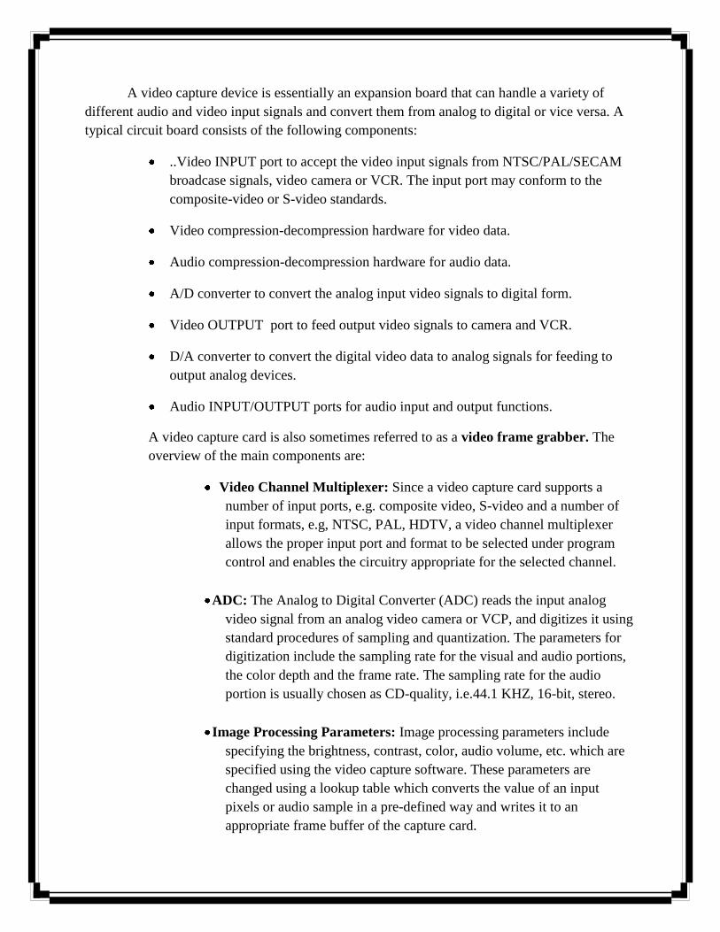
A video capture device is essentially an expansion board that can handle a variety of
different audio and video input signals and convert them from analog to digital or vice versa. A
typical circuit board consists of the following components:
..Video INPUT port to accept the video input signals from NTSC/PAL/SECAM
broadcase signals, video camera or VCR. The input port may conform to the
composite-video or S-video standards.
Video compression-decompression hardware for video data.
Audio compression-decompression hardware for audio data.
A/D converter to convert the analog input video signals to digital form.
Video OUTPUT port to feed output video signals to camera and VCR.
D/A converter to convert the digital video data to analog signals for feeding to
output analog devices.
Audio INPUT/OUTPUT ports for audio input and output functions.
A video capture card is also sometimes referred to as a video frame grabber. The
overview of the main components are:
Video Channel Multiplexer: Since a video capture card supports a
number of input ports, e.g. composite video, S-video and a number of
input formats, e.g, NTSC, PAL, HDTV, a video channel multiplexer
allows the proper input port and format to be selected under program
control and enables the circuitry appropriate for the selected channel.
ADC: The Analog to Digital Converter (ADC) reads the input analog
video signal from an analog video camera or VCP, and digitizes it using
standard procedures of sampling and quantization. The parameters for
digitization include the sampling rate for the visual and audio portions,
the color depth and the frame rate. The sampling rate for the audio
portion is usually chosen as CD-quality, i.e.44.1 KHZ, 16-bit, stereo.
Image Processing Parameters: Image processing parameters include
specifying the brightness, contrast, color, audio volume, etc. which are
specified using the video capture software. These parameters are
changed using a lookup table which converts the value of an input
pixels or audio sample in a pre-defined way and writes it to an
appropriate frame buffer of the capture card.

Compression Decompression: The video capture card often contains a
chip for hardware compression and decompression of video data in real
time. There can be multiple standards like MPEG-1, MPEG-2,
H.261/263, which would require a programmable CODEC on the card.
3. Video Capture Software
Tuning Parameters
AVI capture
AVI to MPEG Converter
MPEG Capture
DAT to MPEG Converter
MPEG Editor
VIDEO FILE FORMATS AND CODECs
AVI (Audio/Video Interleaved)
MOV (QuickTime Movie)
MPEG (Motion Pictures Experts Group)
Real Video
H.261
H.263
Indeo Video Interactive
Cinepak
Sonenson Video
VDOLive
DivX
XviD
Windows Media Video (WMV)
VIDEO EDITING:
Online and Offline Editing
SMPTE Time Code

Timebase
Edit Decision List(EDL)
VIDEO EDITING SOFTWARE
Importing Clips
Timeline Structure
Playback of Clips
Trimming Clips
Splitting a Clip
Manipulating the Audio Content
Adding Transitions
Changing the speed of a Clip
Changing the Opacity of a Clip
Applying Special Effects
Superimposing an Image
Exporting a Movie
CONCLUSION:
While editing and exporting digital video, a concept which needs to be understood is
called rendering. A video editor provides us with a visual interface where we can click and
drag to specify editing operations on video operations. This process of physically changing
the data based on some instruction given via an interface is known as rendering. Depending
on the amount of video data and the nature of operations rendering may often span for
several hours and even for days. In most cases AVI and MOV formats are usually supported,
in some cases creating other formats like MPG may also be possible.