Embed Size (px)
Citation preview

8/3/2019 Elect Circuits Link 2
http://slidepdf.com/reader/full/elect-circuits-link-2 1/7
Electrical Symbols
delta science modules Electrical Circuits1
a c tiv i t y
Electrical SymbolsOBJECTIVES
In this activity, students discover theusefulness of symbols used to identify partsof a circuit.
The students
draw and interpret circuit diagrams
construct circuits from simple circuitdiagrams
compare brightness of bulbs in differentcircuits
SCHEDULE
About 40 minutes
VOCABULARY
battery terminal
circuit diagram
MATERIALS
For each student
1 Activity Sheet 2
For each team of two
2 batteries, D-cell
2 battery holders
2 bulb holders
2 bulbs, flashlight, #48
4 electrical clips
4 pcs wire, copper, insulated, 15-cm
For the class
1 roll wire, copper, insulated
1 pair wire cutters
PREPARATION
Make a copy of Activity Sheet 2 for eachstudent.
Gather the pieces of wire from Activity 1.Cut and strip the ends of three new 15-cm(6-in.) pieces of insulated copper wire foreach team.
Practice placing batteries and electricalclips into the battery holders. Place theclips in first, each so the Fahnestock clip(which is already attached at the top)
points to the outside. Then push thebattery down into the holder. To attach thewire, push the tab on the Fahnestock clipso that the loop protrudes. Place the endof a wire through this loop and release thetab. When correctly assembled, the end of the wire will be held securely in place (seeFigure 2-1).
Each team of two will need two batteries,two battery holders, four electrical clips,four pieces of wire, two bulbs, and twobulb holders.
22
1
2
3
4
Figure 2-1. An assembled battery holder.
© Delta Education LLC. All rights reserved.

8/3/2019 Elect Circuits Link 2
http://slidepdf.com/reader/full/elect-circuits-link-2 2/720
activity 2 Electrical Symbols
Additional Information
BACKGROUND INFORMATION
Most battery cases are marked positive (+) onone end and negative (–) on the other. Thesemarkings indicate the positive and negativebattery terminals. The direction of the electriccurrent in a closed circuit is from the negative
(–) terminal of the battery to the positive (+)terminal of the battery. Therefore, the batteryterminals are where wires connecting thebattery to the circuit should be attached.
To make the drawing of electric circuits easier,a series of symbols has been standardized torepresent electrical components. A drawing of a circuit using these symbols is called a circuit diagram.
In this activity, students learn how to draw and
interpret circuit diagrams.
Review the concept of closed circuit,emphasizing that the path of electric current
is from one end of the battery back to theother end of the battery.
Draw a battery on the board. Be sure toillustrate the shapes of both the positive (+)and negative (–) ends of the battery, andposition the battery vertically.
Bring the students’ attention to the positiveand negative ends as you draw a plus (+) anda minus (–) on the battery case next to theappropriate end.
Write battery terminal on the board to the leftof your drawing. Explain that, in a closedcircuit, current flows from the end of thebattery marked negative (–), through theparts of the circuit, back to the end of thebattery marked positive (+). The positive andnegative ends of the battery are called battery terminals.
The negative side is sometimes not marked but it is the side opposite the positive side.The positive side is usually marked and isalways the side with the nib.
Activity Sheet 2
These symbols are used to draw circuit diagrams.
Circuits A and B may also be shown by Circuit Diagrams A and B.
1. Draw a circuit diagram of a circuit that contains two batteries andtwo bulbs.
2. Circuit diagrams will be used often in the remaining activities.Practice reading them. Then build Circuits A, B, and C.
Circuit A Circuit B Circuit C
Which circuit had the brightest bulb?
Electrical Symbols
battery wire bulb
material
symbol
+
–
+ –
+ –
+ –
Circuit A Circuit B
Circuit Diagram A Circuit Diagram B
Circuit B
1
2
Guiding the Activity
© Delta Education LLC. All rights reserved.

8/3/2019 Elect Circuits Link 2
http://slidepdf.com/reader/full/elect-circuits-link-2 3/7
Figure 2-2. A circuit.
Figure 2-3. Symbols, a circuit diagram, and a circuit.
a. symbols b. circuit diagram c. circuit
delta science modules Electrical Circuits2
Additional Information
Point to your drawing of the battery and tellthe students to watch as you draw two wiresand a bulb to make a circuit (see Figure 2-2).
Ask, How do you think that we could make
this drawing more quickly and easily?
Explain that there are many benefits to usingsymbols when drawing circuits. For example,the symbols representing the parts of thecircuit are standardized so that everyoneunderstands which component is beingrepresented and no one has to be particularlyartistic to draw the symbols.
Draw the symbols of a battery (includingpositive and negative terminals), a wire, and a
bulb on the board (see Figure 2-3a).
Students may suggest using symbols to
represent the various components of thecircuit.
Guiding the Activity
3
4
© Delta Education LLC. All rights reserved.

8/3/2019 Elect Circuits Link 2
http://slidepdf.com/reader/full/elect-circuits-link-2 4/722
activity 2 Electrical Symbols
Additional Information
Point to each symbol and identify whichcircuit element the symbol depicts. Explainthat the longer horizontal line in the batterysymbol depicts the positive (+) terminal and
the shorter horizontal line depicts thenegative (–) terminal.
Write the words circuit diagram on the board.Explain that now that students know thesymbols that represent the parts of the circuit,they can connect these symbols to make adrawing of a circuit. A drawing of a circuitusing symbols is called a circuit diagram.
Have students tell you where to move yourfinger to trace the path of electric current
through the circuit depicted by the circuitdiagram.
Have a student volunteer come to the front of the room and, using the materials from one of the teams, assemble the circuit shown in thecircuit diagram. Once the circuit is completedcorrectly (as shown in Figure 2-3c), hold it upfor all students to see.
Tell students that they are going to look atsome circuit diagrams and then build the
circuits represented.Distribute a copy of Activity Sheet 2 to eachstudent. Distribute two bulbs, two bulbholders, four wires, four electrical clips, twobatteries, and two battery holders to eachteam.
Remind them of the symbols that depict partsof a circuit. Bring their attention to theillustrations and the circuit diagrams of Circuits A and B. Tell them to notice in Circuit
Diagram B how two symbols for a battery areplaced next to each other to indicate twoconnected batteries.
Draw a circuit diagram, as shown inFigure 2-3b, next to the symbols.
Make sure that they begin at the negativeterminal of the battery symbol (the shorter
horizontal line) and proceed through the circuit elements back to the positive terminal of thebattery symbol (the longer horizontal line).
5
6
7
Guiding the Activity
© Delta Education LLC. All rights reserved.

8/3/2019 Elect Circuits Link 2
http://slidepdf.com/reader/full/elect-circuits-link-2 5/7
delta science modules Electrical Circuits2
Additional Information
Draw Figure 2-4a on the board. Explain that inorder to help students visualize theconnection between the two batteries, twobattery symbols are sometimes drawn as
shown in Figure 2-4a, with a short vertical linedepicting the wire that connects the twobatteries.
Ask, How would you draw a circuit diagramfor a circuit that has two batteries and twobulbs?
Have students draw on their activity sheets acircuit diagram of a circuit that contains twobatteries and two bulbs.
Have students trace the path of electriccurrent through each of the three circuitdiagrams at the bottom of the activity sheet.
Tell students to omit the vertical line in their circuit diagrams but to remember that the twobatteries are in fact connected.
Students may be able to guess that two symbols for bulbs are drawn next to eachother with one connecting line, whichrepresents a third wire.
Remind students that the shorter horizontalline indicates the negative terminal and thelonger line indicates the positive terminal.
Figure 2-4. A two-battery, two-bulb circuit diagram and circuit.
8
Guiding the Activity
a b
© Delta Education LLC. All rights reserved.
8/3/2019 Elect Circuits Link 2
http://slidepdf.com/reader/full/elect-circuits-link-2 6/7
Additional Information
24activity 2 Electrical Symbols
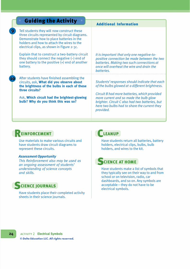
Tell students they will now construct thesethree circuits represented by circuit diagrams.Demonstrate how to place batteries in theholders and how to attach the wires to the
electrical clips, as shown in Figure 2-3c.
Explain that to construct a two-battery circuitthey should connect the negative (–) end of one battery to the positive (+) end of anotherbattery.
After students have finished assembling thecircuits, ask, What did you observe about the brightness of the bulbs in each of thesethree circuits?
Ask, Which circuit had the brightest-glowing bulb? Why do you think this was so?
It is important that only one negative-to- positive connection be made between the twobatteries. Making two such connections at once will overheat the wire and drain thebatteries.
Students’ responses should indicate that eachof the bulbs glowed at a different brightness.
Circuit B had more batteries, which provided more current and so made the bulb glow brighter. Circuit C also had two batteries, but here two bulbs had to share the current they provided.
Guiding the Activity
REINFORCEMENT
Use materials to make various circuits andhave students draw circuit diagrams torepresent these circuits.
Assessment Opportunity This Reinforcement also may be used asan ongoing assessment of students’ understanding of science conceptsand skills.
SCIENCE JOURNALS
Have students place their completed activitysheets in their science journals.
CLEANUP
Have students return all batteries, batteryholders, electrical clips, bulbs, bulbholders, and wires to the kit.
SCIENCE AT HOME
Have students make a list of symbols thatthey typically see on their way to and fromschool or on television, radio, cardashboards, and so on. Any symbols areacceptable—they do not have to be
electrical symbols.
10
9
© Delta Education LLC. All rights reserved.

8/3/2019 Elect Circuits Link 2
http://slidepdf.com/reader/full/elect-circuits-link-2 7/7
delta science modules Electrical Circuits2
Connections
Science Extension
Remind students of their discussion of electrons and static electricity in the Scienceand Language Arts connection in Activity 1.
Then give students an opportunity toexperiment with static electricity. Forexample, they could rub balloons againsttheir clothing and then stick the balloons on awall. They also could rub a plastic comb witha wool cloth and then bring the comb close tosmall bits of paper, which will “jump” to thecomb. Encourage students to offer their ownsuggestions for other ways to create staticelectricity. Explain that rubbing an objectgives it a negative charge. Just like the
opposite poles of two magnets, a negativelycharged object and a positively chargedobject are attracted to each other. Electronswill flow from the negatively charged object tothe positively charged object until the twoobjects have equal charges. Also explain thatin a battery, the electrical current—the flow of electrons—is created by chemical interactionsinside the battery. When the terminals areconnected in a circuit, electrons will continueto flow from the negative terminal to thepositive terminal as long as the chemical
interactions continue.
Science Challenge
Have students do the following activity afterthey explore static electricity in the ScienceExtension connection. Each pair or team of students will need an Ne2 neon light bulb(available from an electronics store), areclosable plastic sandwich bag, and a swatchof wool or silk cloth. As an alternative, youcould put one set of materials at a workstation and let students take turns doing theactivity. Tell students to spread the leads of the bulb so they point in opposite directionsand then seal the bulb in the plastic bag. Havestudents rub one side of the bag with thecloth as they watch the bulb. (It will glowfaintly.) Ask students to explain what made
the bulb light. (An electrical current, thedischarge of static electricity, flowing fromone side of the plastic bag to the other side.)Based on what they learned about static
electricity in the Science Extensionconnection, what can they infer about theelectrical charges on the sides of the plasticbag? (Rubbing one side of the bag gave it anegative charge. The other side had a positivecharge, so electrons “jumped” from thenegatively charged side to the positivelycharged side, passing through the bulb andmaking it glow.)
Science and Careers
Invite an electrician, an electrical engineer, orsomeone who teaches electrical wiring at avocational school to visit the class. Ask thevisitor to bring samples of circuit diagrams toshow students. Encourage students toprepare a list of questions to ask the visitorabout his or her work and the training andeducation it requires.
Science and Health
Ask students whether they have seen high-tension power lines that are used to transmitelectricity over long distances. Explain thatthe powerful electric current running throughthe wires creates strong electric and magneticfields. These fields produce a type of energycalled electromagnetic radiation, or EMR.Many people, including some scientists,believe that long-term exposure to EMR canbe harmful to people. For example, somestudies suggest a link between prolongedexposure to EMR and increased risk of
developing cancer. Encourage interestedstudents to research and report on this issue.
You may want to hold a class debate, withvolunteers taking either side.
© Delta Education LLC. All rights reserved.