Embed Size (px)
Citation preview
Elastic, Plastic &Collapse Characteristicsof
Structural Welded Connectionsby
Lynn S. Beedle
A SUMMARY OF A DISSERTATION
Presented to the Graduate Faculty
of Lehigh University
in Candidacy for the Degree of
Doctor of Philosophy
Reprinted, front the
RESEARCH SUPPLEMENT TO THE WELDING' JOURNAl.
August i951 and November 1952
Eonneutions for Welded UontinnonsPortal FramesProgress Report No.4: Part II~ttTheoreticalAnalysis ofStraight Knees" *
• Theoretical analysis for straight knees of a rigidframe stru~
ture forming the basis for comparing experimental resultswith theory. Stresses rotations and deflections are considered
by Lynn S. Beedle, A. A.Topractsoglou and Bruce
. G. Johnston
Foreword
Part I of this report appeared in theJuly 1951 issue of Welding Research Supplement. It included a presentation of testresults for 15 welded corner connections ofvarious types and a discussion of knee requirements.~art II, presented here, contains the
theoretical alll~.Iysis for straight knees,forming the basis for a comparison of experimental results with theory. Stresses,rotations and deflections are considered.
Part III of this Progress Report No. 4will appear in a later issue of THE WELDING JOURNAL and will include the discus~ion of test results and the conclusions.
I. ELASTIC ANALYSIS
F BLEICH26t' has proposed approximate methods for stress analysis and
• design of square knees. He assumesthat for square knees: " ... where the ratioof the length of the restraining arm to ,itsdepth is equal to or larger than one, theNavier theory yields sufficiently accurateresults and one may determine the fiberstresses and shear stresses according to theconventional ·theory." By "restraining
arm" is meant the arm AD, which acts torestrain the girder, Fig. 58. t
In the rolled section adjacent to theknee (at section AD) it has also been assumed that the ordinary beam theoryapplies for predicting stresses and deformations.
1. Stress Analysis of Straight Knees*Without Diagonal Stiffeners
(a) Identical Rolled Shapes
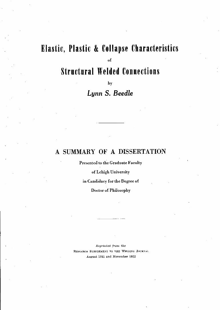
Consider connection type 7, shown inFig. 59 (a). The stresses in the kneeABCD are found by making the followingassumptions:
L The bending moment at the sectionAD is carried entirely by the flanges. Inthe knee shown, M r = V(L - (d/2)) andthe portion of the flange force, F, due tobending is given by
, F = ~r ~ v(~ - D• The terms "square" and Ilstraight" are both
used to designate a connection in which the girder 'and column rolled sections are joined at rightangles without the use of additional haunch orbracket material.
t Figure numbers continue the same sequencecommenced in Part I.
oC Fi===::n;::::~----_,.
The designation M r will be used throughout this report to indicate the moment atthe end of the rolled section and beginningof the knee, whether it be straight, curvedor haunched. M h is then used to denotethe "haunch" moment or moment at theintersectioJi of the neutral lines of thegirder and column. In the above expression the remaining terms are defined by
. Fig. 59.2. Shearing force, V, is taken by the
web and, is uniformly distributed.3. The normal force, N, is considered.
It is assumed to act at the flanges, however, as shown in Fig. 60.
4. The flange force varies linearly between D and C, with maximum at D andzero at C.
5. Stress concentrations are not considered. "
6. Restraint due to bending of individual flange elements is neglected.
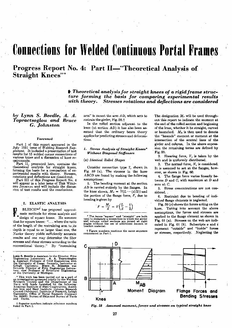
Fig. 59 (c) shows the forces acting on theknee. Taking into account the aboveassumptions, the forces and stresses are
, applied to the flange element as shown inFig. 61 (a). Stresses on the web are indicated in Fig. 61 (b). Subscripts 0 and irepresent "outside" and "inside" forcesor stresses, respectively. ,Neglecting the
,...--t---, ---
KneeFig.58 Assumed moment, forces and stresses.on typical straight knee
t~
Lyn'n S. Beedle is Assistant to the Director, FritzEngineering Laboratory. A. A. Topractsoglouis Assistant Professor of Civil Engineering withthe University of Texas; formerly, Instructor atLehigh University. Bruce G. Johnston wasformerly Director of Fritz Engineering Laboratory, now Professor of Structural Engineeringat the University of Michigan.
• This work has been carried out as a part ofan investigation sfonsored jointly by the WeldingResearch Counci and the Department of theNavy with funds furnished by the following:American Institute of Steel Construction, American Iron and Steel Institute, Column ResearchCouncil (Advisory), Institute of Research, LehighUniversity, Office of Naval Research (ContractNo. 39303), Bureau of Ships and Bureau of Yardsand Docks.' ,
t Superior numbers indicate ~f~rence numberslisted in Part I.
27
L(- - I)d
Mr _J!.'Dt'" 5 A
---~l H' tI ~ ,'(,
't.l -,- tI ~.. ..- ~i--
(b) Str....ses oD_Web
F. VAF = A,
,r--_~
"tL
rcreL,---
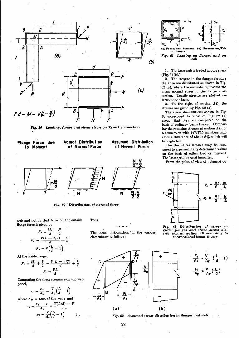
1. The knee web is loaded in pure shear(Fig. 61 (b).)
2. The stresses in the flanges formingthe knee are distributed as shown in Fig.62 (a), where the ordinate represents themean normal stress in the flange crosssection. Tensile stresses are plotted external to the knee.
3. To the right of section AD, thestresses are given by Fig. 62 (b).
The stress distributions shown in Fig.63 correspond to those of Fig. 62 (b)except that they are computed 'on thebasis of ordinary beam theory. Compar~
ing the resulting stresses at section AD fora connection with 14WF30 members indicates a difference of about 8% which willbe neglected.
The theoretical stresses may be compared to experimentally determined valueson the basis of either load or moment.The latter will be used hereafter.
From the point of view of balanced de-
Fig. 61 Loading on flanges and on,web
Fig. 63 Distribution of stress ingirder flanges and shear stress distribution at section AD according to
conventional beam theory
rr=;:::;;;:::;;~-F.I 'to 1''(. 'tip 1/
I~:g'tl;:.!..~_~l.,.... -F1~ y- tA
F. ,Fj(0) Forees and Str....ses
on Flanges .
-+
- -...-
::LAw
(0) (b)
Fig.62 Assumed stress distribution in flanges and web
Assumed Distributionof Normal Force
To = Ti
The stress distributions' in the variouselements are as follows:
Thus
-~- (bJ'
Ii;=-='=====;i1L-FVx
Actual Distributionof Normal Force
------- (elfI, -N.
ptF8\ ty
F N F
oc
D--,-
I /,. I
" . / F·~, I d
J ,-
__ F. =£.(~_ 1).• - A.. A.. d
where AID = area of the web; and
Fi - V V(L/d) - VTi=~= I A..
T' = £.(f - 1) (1).• A.. d
Flange Force dueta Moment
Fig. 60 . Distribution of normal force
Fig.59 Loading, forces and shear stress on Type 7 connection
web and noting that N = V, the outsideflange force is given by
F. = ~r _ ~
F_ V(L - d/2) _ !::'
• - 'd 2
F.=V(~-I)
At the inside flange, ,F' ,;" M r +.!::' = V(L - d/2) + .!::'
• d 2 d 2VL
Fi=d
Computing the shear stresses T on the webpanel,
I
'1/- '- f 1----- -
B I A -I (a)
C
f d- M=:a Y{L-fJ
28
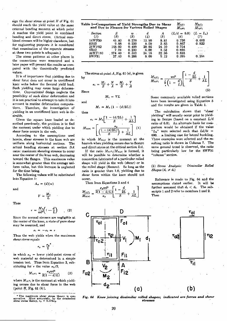
Table l-Comparison of Yield Strengths Due to Shear MA(T) Mh(T)
and Due to Flexure for Various Rolled Shapes MA(er) MA(er)
Section S w d A (Lid = 6.0) (L = L u )
(1) (2) (3) (4) (5) (6) (7)14WF30 41.80 0.270 13.90 8.81 0.726 0.6938B13 9.88 0.230 8.00 3.83 0.867 0.82221WF82 168.00 0.499 20.86 24.10 0.7546B12 7.24 0.230 6.00 3.53 0.66624WFllO .274.40 0.510 24.16 32.36 0.6338WF31 27.40 0.288 8.00 9.12 0.395 0.364
(4)
sign the llhear stress at point· H of Fig. 61should reach the yield value at the sameexternal bending mmnent at which pointA reaches the yield point in combinedbending and direct stress. (Actual combined stresses will be higher elsewhere, butfor engineering purposes it is consideredthat examination of the separate stressesat these two points is adequate.)
The stress patterns at other places inthe connections were measured and alater paper will present the results as compared with the' theoretically predictedvalues.
It'is of importance that yielding due toshear fOfce does not occur in unstiffenedknee webs below the flexural yield load.Such yielding may cause large deformatiom. Conventional design neglects thepossibility of such shear deformation andit is not practical to attempt to take it intoaccount in routine deformation computations.. Therefore, the investigation ofyielding in an unstiffened knee web is de
.sirable.Given the square knee loaded as de
scribed previously, the problem is to findthe moment under which yielding due toshear force occurs in the web.
According to the assumptions usedherein, shear stresses in the knee web areuniform along horizontal sections. Theactual bending stresses at section DAcause maximum shearing ~tresses to occur,near the center of the knee web, decreasingtoward the flanges. This maximum valueis somewhat greater than the average uniform value, but this increase is neglectedfor the time being.
The following values will be substitutedinto Equation 1:
A", = (d)(w)
and
v = M A
L
The stress at point A, Fig. 61 (a), is givenby
IT. = M, + 1i = M, + YS A S A
Since
and
M, = M A (1 - (dI2L»
then
IT. = M{l - ~/2L) + AlL]
MAcer) = [ C- ~/2f») + AJin which M h(er) is the moment at thehaunch when yielding occurs due to flexureand direct stress at the critical section DA.
If the ratio Mh(T)IMh(er) is formed, itwill be possible to determine whether aconnection fabricated of a particular rolledshape will yield in the web (shear) or inthe rolled shape (flexure). So long as theratio is greater than 1.0, yielding due toshear force within the knee should notoccur.
Then from Equations 3 and 4
Mw ) 2(lIT~w:~L)[1 - 2~ + .-!-JMAcer) = lTv S .AL
wd2 [1 -;L' 1]~'(~L) -S +AL~ 1 - -
(5)
Some commonly available rolled sectionshave been investigated using Equation 5and the results are given in Table 1.
The calculation shows that "shearyielding" will usually occur prior to yielding in flexure (based on a c~nstant Lidratio of6.0). An alternate basis for comparison would be obtained if the value"Lu " were selected such that Ldlbt =600...0. limiting case for lateral buckling.Three examples were selected and the resulting ratio is shown in Column 7. Thesame general trend is observed, the ratiobeing particularly low for the 8WF31"column" section.
(b) Stress Analysis: Dissimilar RolledSnapes (d, ¢ d2 )
Reference is made to Fig. 64 and theassumptions. stated earlier. It wi)) befurther assumed thal, d2 < d lo The sub..scripts 1 and 2 refer to members 1 and 2.Then
Thus
0"1 == - (7'2 == T
Thus the web yields when the maximumshear strcss equals '
• The maximum shear stress theory is conservative. More accurately. by the octahedralshear stress theory, TV = O.578erv.
C D Tal
F;I rTal .II
VI )MI dl_~!2 .T~ tTi2
To2iI
~~il
B1 V2 ,~ .Til
Fo2 '-..;:./ 12M2
d2 (0) (b)Fig. 64 Knee joining dissimilar rolled shapes; . indicated are forces and shear
stresses
29
. (2)T = MA(I_~)wd2 L
Since the normal stresses are negligible atthe center of the knee, a state of pure shearmay be assumed, and
in which lTv = lower yield-point stress ofweb material as determined in a simpletension test. Thus from Equation 2, subs~ituting for T the value ITv12,
IT wd2
MA(T) = 2(1 ~ dlL) (3)
where Mh(T) is the moment at which yielding occurs due to shear force in the web(point H, Fig. 61 (b» .
Since
Also
_ (d. +d2 )] (10)2L
2. Rotation Analysis
and
Secondly, residual stress is built up inthe knee due to welding of the stiffeners.Presumably this alone would cause yieldingto occur at a lower load than predicted:
• Designation of connection types was established in Part'l, Fig; 4; straight connections incl uded in the test program are shown in Fig. 8.
where
1'7 shear rotation of Type 7 connec-tion.
G modulus of elasticity in shear. ,
The rotation due to bending momentmay be determined from the elongations orcontractions, of the flanges. As statedearlier, it is assumed that the web carriesall the shear force and the flange elemeatscarry the direct stresses.
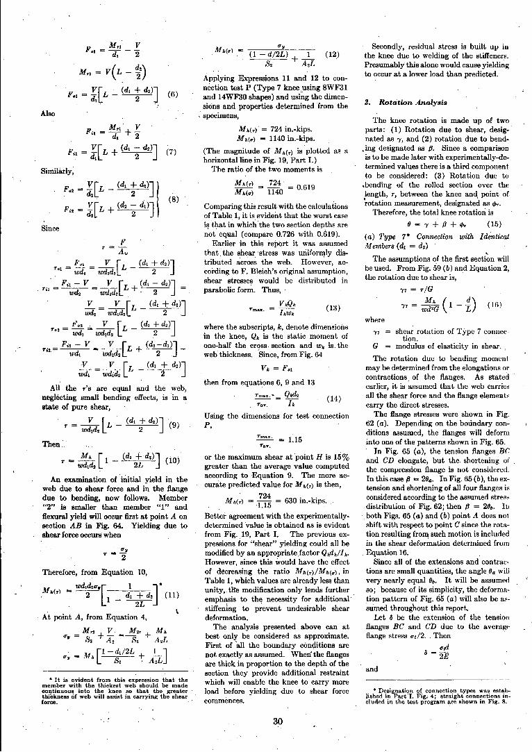
The flange stresses were shown in Fig.62 (a). Depending on the boundary conditions assumed, the flanges will deforminto one of the patterns shown in Fig. 65.
In Fig. 65 (a), the tension flanges BCand CD elongate, but the, shortening ofthe compression flange is not considered.In this case fJ = 28a. In Fig. 65 (b), the extension and shortening of all four flanges isconsidered according to the assumed stress
,distribution of Fig. 62; then fJ = 28&. Inboth Figs. 65 (a) and (b) point A does notshift with respect to point C since the rotation resulting fro1l\ such motion is includedin the shear deformation determined from
, Equation 16.Since all of the extensions and contral:
tions are small quantities, the angle,8a willvery nearly equal 8b. It will be assumedso; because of its simplicity, the deformation pattern of Fig. 65 (a) will also be a$sumed throughout this report.
Let & be the extension of the tensionflanges BC and CD due to the averagpflange stress ITtl2. Then '
(fld
& = 2E
The knee rotation is made up of twoparts: (1) Rotation due to shear, desig-'nated as 1', and (2) rotation due to bend-
o ing designated as fJ. Since a comparison, is to be made later with experimentally-de
termined values there is a third componentto be considered: (3) Rotation due to
.bending ef the rolled section over thelength, r, between' the knee and point of~otation measurement, designated as "',.
Therefore, the total knee rotation is
8 = l'+ fJ + I/>r (15)
(a) Type 7* Connection with ldentir,alMembers (dt == d2)
The assumptions of the first secti~n willbe used. From Fig. 59 (b) and Equation 2,the rotation due to shear is,
1'7 = T/G
1'7 = W~~ ( 1 - i) (Hi)
, Mh(u)
or the maximum shear at point H is 15%greater than the average value computedaccording to Equation 9. The more accurate predicted value for M h(r) is then,
M 724 630' k'h(r) = -1.15 = lll.- IpS.
Better agreement with the experimentallydetermined value is obtained as is evidentfrom Fig. ,19, Part I. The previous expressions for "shear" yielding could all bemodified by an appropriate factor Qkddlk.However, since this would have the effectof decreasing the ratio Mh(r)/Mh(u) , inTable 1, which values are already less thanunity" tIte modification only lends furtheremphasis to the necessity for additional'stiffening to p~event undesirable sheardeformation.
The analysis presented above can atbest only be considered as approximate.First of "all the boundary conditions arenot exactly as assumed. When· the flangesare thick in proportion to the depth of thesection they provide additional restraintwhich will enable the knee to carry moreload before yielding due to shear forcecomintmces.
Tmax. = {15Tav.
then from equations 6, 9 and 13
Tmax.- Qtd2 (14)Tav, = h
Using' the dimensions for test connectionP,
where the subscripts, k, denote dimen~ions
in the knee, Qk is the static moment ofone-half the cross, section and Wk is, theweb thickness.·Since, from Fig. 64
Vk = F••
Mh(r) = 724' = 0619Mh(u) 1140 .
Comparing this result with the calculationsof Table I, it is.6vident that the worst casei~ that inwhich the two section depths arenot equal (compare 0.726 with 0.(19).
Earlier in this report it was assumedthat, the shear' stress was uriiformly distributed acros~ the web. Howe~er, according to F. Bleich's original assumption,shear stresses would be distributed inparabolic form. Thus,'
V,.QkTmax. = hWk (13 Y
Mh(r) = 724 in.-kips.Mh(U) = 1140 in.-kips.
(The magnitude of Mh(r) is plotted as ahorizontal line in Fig. 19, Part I.)
The ratio of the two moments is
(1 - d/2L) + _1_ (12)82 A 2L
Applying Expressions 11 and 12 to connection test P (Type 7 knee,using 8WF31and 14WF30 shapes) and using the dimensions and properties determined from the
, specimens,
(6)
(8)
An examination of initial yield in theweb due to shear force and in the flangedue to bending, now follows. Member"2" is smaller than member "I" andflexural yield will occur first at point A onsection AB in Fig. 64. Yielding due toshear force occurs when
• It is evident from this expression that themember with the thickest web should be madeoontinuous into the' knee so that the greaterthickness of web will assi.t in carryinll: the shearforce. '
FMr.' V
'·=(4+2
Fil = ~[L + (d. ; ~)] (7')
Similarly;
F.2
= ![L _ (d. + d2 )]
, ~ 2
F' 2 = r[L + (d2; d~)J
Therefore, from Equation 10,
Wd.d2ITU[ IJ *Jlh(r) = -2- 1 _ d. +~ (11)
, 2L
, At point A, from Equation 4,
=Mr2+!::.'=~2r+ MhfTr 82 A2 82 A'J.L
IT. = Mh[l-d1/2L +l.-]8 2 ,A.L
30
Assuming the r-distances' and E-valuesidentical for the two members,
tP, =t/>r. + t/>r2
_ ~[(1- ~) + (1 - it)]t/>r - 1'. E I. 1
2
(22)
Combining Equations 20, 21 and 22, thetotal rotation of a Type 7 connection withdissimilar members is given by
87 = (-Y7 + fJ7 + tP,). [1 _(d. + d.)2L
87 = Mh ddG +.w.. .1 1(1 ~ ~)d. +( 1 - :L)d. t
IE 1Ft /P2) +
~.~ 0. - :~) + (1 - iL)l J(23)E (I, I 2 )
Computing the total rotation for connection P,
9r = ('Y7 + fJ7 + t/>r)87 ,;,. (2.440 + 1.171 + 0.777) X
10-1 M h rad.
9r =4.39 X 10⁻¹ M h rad.
ThiH theoretical moment-angle cb8nge relationship is plotted with the experimentalvalues in Fig. 19, Part I. The relativemagnitude of the components 'Y1I IJr andtPr may be seen in the calculation aboveand it will be noted. that the shear component is the largest.
4>,.= rl [~: ( 1 - ~)]
4>T2 = r{;{i (1 - ;1:)]
(c) Connections with Diagonal Stiffeners
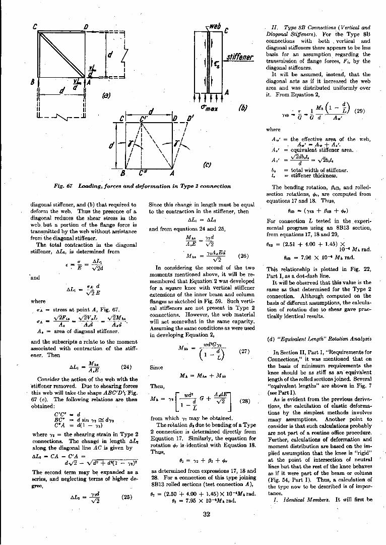
I. Type S Connections. Rotations dueto shear in the square knee ABCD reinforced with diagonal stiffeners (Fig. 67)will be found by making the followingassumptions: .
(a) The thrust of the two compressiveforces VaL/dis taken by the stiffeners atpoint A. The necessity' for the designation, Va, will. be described later.
(b) The stress in the diagonal stiffenervaries linearly from a maximum at A tozero at C. It was assumed earlier that the'force, Fo, was transmitted uniformly tothe web along the length CD (Fig. 67). Aportion of this shear, then, is transmitted·to the stiffener in proportion to the lengthof web intercepted by it.
(e) Stress concentrations are disregarded.
From assumption (b) it follows th~t thestiffener stresses cause uniform shear, TI, inthe web of the knee. See Fig. 67 (b)•.
The moment required to deform a Type2 connection in shear consists of two ]t8ltB:(a) ~ht' moment necessary to shorten the
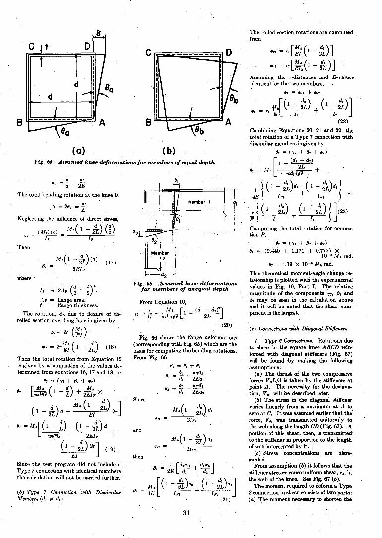
The rolled section rotations are computed :from
(b)
B
c ~-:::=-~--;;:--==-:::l--~D~
I H
II
!Member I
'~. f- . -- -'-
.1 ,-; 8'f I
I
1::---- - -- -~
21Member
'2 I
1
Mh(l-tL)d.tT" 2IFI
~-- d2---,-.J
Fig. 6f!. Assumed knee deformationsfor members of unequal depth
From Equation 10,
. T _ _.Mh [1 _(d. + d2)']1'7 = G - lI'd,d,G .2L
. (20)
{:J, =
Fig. 66 shows the flange deformations(corresponding with Fig. 65) which are thebasis for computing the bending rotations.From Fig. 66
Since
and
then
(17)
d
(0)
Mh( 1 -!L). (d)
2EIF
t-
Fig.65 Assumed knee deformations for members of equal depth
c
where .
8 at8. = d = 'i.E
The total b!lnding rotation at the knee is
atfJ ~ 28. = E
Neglecting the influence of direct stress,
(M,)(c) Mh( 1 ~ k) (nat = ----r;-"= /p
Then
(b) Type 7 Connection with DissimilarMembers (d. ;of' d2 )
IF 2AF G- ~rAp == flange area.t flange thickness.
The rotation, tP" due to flexure of therolled section over lengths r is given by
tP,= 21' (~;).
tPr = 2r~; (1- 2~) (18)
Then the total rotation from Equation 15is given by a summation of the values de- .termined from equations 16, 17 and 18, or
(17 = ('Y7 + fJ7 + tP,)
[ Mh ( d) Mh9r = wd2G 1 - L + 2EIp X
(1 _ ~) d + Mh ( 1 - 4i). 2 J
. 2L EI r
9r = Mh[(1 - f) (1- ~)d .wd 2G + . 2E/P +
( 1 - ~) 2rJ (19)EI
Since the test program did not include aType 7 connection with identical members I .
the calculation will not be carried further.
31
Mh (1 - t!..).. 1 L (29)1'8B = G = Gd A..'
. II. Type 8B Connections (Vertical andDiagonal Stiffeners). For the Type 8Bconnections with both. vertical anddiagonal stiffeners there appears to be lessbasis for an assumption regarding thetransmission of flange forces, Ft, by thediagonal stiffeners.
It will be assumed, instead, that thediagonal acts as if it increased the webarea and was distributed uniformly overit. From Equation 2,
c-===~ web c
it
itt,; stiffener
i t(a) t t tt A
crmBJC (6)
cl
(C)
where
A.'
= the effective area of theA..' = A.. + A,'.
= equivalent stiffener area.
= v2db,t, = v2b.t.d
= total width of stiffener.= stiffener thickness.
web,
Fig. 67 Loading, forces and deformation in Type 2 connection The bending rotation, f38B, and rolledsection rotations, q", are computed fromequations 17 and 18. Thus,
98B = (1'8B + f38B + q,,)
For connection L tested in the experimental program using an 8B13 section,from equations 17,18 and 29,
98B = (2.51 + 4.00 + 1.45) X10-8 Mh rad.
98B = 7.96 X 10--11 MA rad.
This relationship is plotted in Fig. 22,Part I, as a dot-<lash line.
It will be observed that this value is thesame as that determined for the Type 2connection. Although computed on thebasis of different assumptions, the calculation of rotation due to shear gave practically identical results.
In Section II, Part I, "Requirements forConnections," it was mentioned that onthe basis of minimum requirements theknee should be as stiff as an' equivalent .length of the rolled sections joined. Several"equivalent lengths" are shown in Fig. 7(see Part I).
As is evident from the previous derivations, the calculation of elastic deformations by the simplest methods involvesmany assumptions. Another point toconsider is that such calculations probablyare not part of a routine office procedure.Further, calculations of deformation andmoment distribution are based on the implied assumption that the knee is "rigid"at the point of intersection of neutrallines but that the rest of the knee behavesas if it were part of the beam or column(Fig. 54, Part I). Thus, a calculation ofthe type now to be described is of importance.
I. Identical Members, It will first be
(d) "Equivalent Length" Rotation Analysis
(28)
from which 1'2 may be obtained.The rotation 132 due to bending of a Type
2 connection is determined directly fromEquation 17. Similarly, the equation forrotation 4>r is identical with Equation 18.Thus,
Then,
as determined from expreBBions 17, 18 and28. For a connection of this type joining8B13 rolled sections (test connection A),
92 = (2.50 + 4.00 + 1.45) X 1O-8Mhrad.92 = 7~95 X 1O-8MA rad.
Since
Since this change in length must be equalto the contraction in the stiffener, then
tiLl = tiL2
and from equations 24 and 25,
MhG 1'2dA.E = v'2
M - 1'2A,Ed (26)hG- v'2
In considering the second of the two·moments mentioned above, it will be remembered that Equation 2 was developedfor a square knee with vertical stiffenerextensions of. the inner beam and· columnflanges as sketched in Fig. 59. Such vertical stiffeners are not present in Type 2connections. However, the web materialwill act somewhat in the same capacity:Assuming the same conditions as were usedin developing Equation 2,
Mh~ = (:d~~) (27)
(25)
(24)tiLl MhG= A,E
Consider the action of the web with thestiffener removed. Due to shearing forcesthis web will take·the shape ABC'D'rFig.67 (c). The following relations are thenobtained:
C'C' dBC' d sin 1'2 ~ d1'2C'A d(l - 1'2)
where 1'2 = the shearing strain in Type 2connections. The change in length tiLtalong the diagonal line AC is given by
tiLt = CA - C'A =dv2 - Vd2 + d2(1- 1'2)2
The second term may be expanded as, aseries, and neglecting terms of higher degree,
tTA dv'2E
where
tTA = stress at point A, Fig. 67.
v2FiG . v2VGL v 2MhGtTA = ~=~=A;d'
A, = area of diagonal stiffener.
and the subscripts a relate to the momentaBBOciated with contraction of the stiffener. Then
diagonal stiffener, and (b) that required todeform the web. Thus the presence of adiagonal reduces the shear stress in theweb. but a portion of the flange force istransmitted by the web without assistancefrom the diagonal stiffener.
The total contraction in the diagonalstiffener, tiLt, is determined from
. tT tiLlE .:= E = v'2d
'and
32
600r'---,r-~-.,------r----r-----,----.----...,
..... -_..-.........---_ .. -
E.</>•.=
Y2
M. = M p + .(d ) X2 - Ys
2 (. 1 + 0.30tTl/)' ,CEo
.Z, = w(Ys)s.
The infiuence of axial load (neglectedentirely in the discussion) is to cause a reduction in the moment-carrying capacityas predicted by the simple plastic theory.This has been described by Bakerao andalso in Progress Report 2.7 As seen there,
In the' above expressions,Zs = WY2SY2 ='distance from neutral axis to bot
tom of fillet
tT.' = E'(2~s - 1) C
tTs' = 0;30iTl/,d
(32.4)
5. Strain-Hardening Penetrated to aDepth Corresponding to an Extreme FiberStress Equal to 1.3tTI/
M,=Mp + (d ) X'2 - Ys
[I - Ys (z .... ~s)] (32.5)
(32.1)
Z2)!..(32.2)
("Plastic
Mp=520
3. Complete PlasticityHinge")
M3 = tTj,F(Z - Z2) + tTl/"'z2 = M p }
</>3 = 00 (neglecting strain-hardening)
<1>2 = di2(considering strain-hardening) .
(32.3)
4. Strain-Hardening Penetrated .toBottom of Flange Fillet
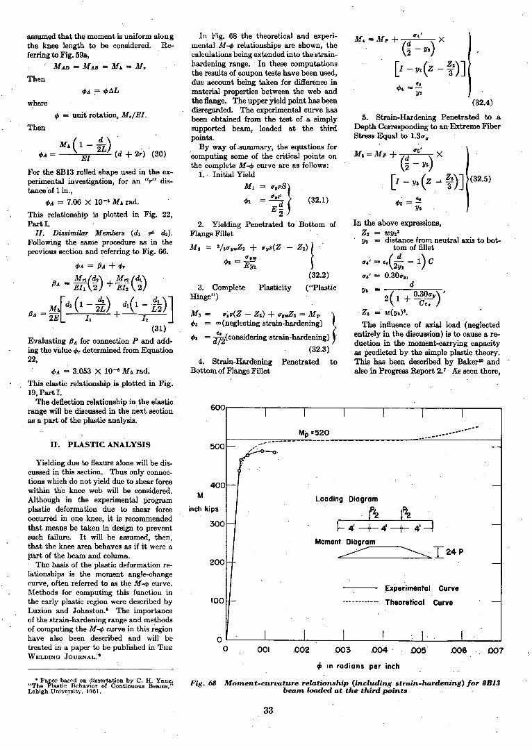
In Fig. 68 the theoretical and experimental M-</> relationships are shown, thecalculations being extended into the strainhardening range. In these computationsthe results of coupon tests have been used,due account being taken for difference inmaterial properties between the web andthe flange. The upper Yield point has beendisregarded. The experimental curve hasbeen obtained from the test of a simplysupported beam, loaded at the thirdpoints.
By way of .summary, the equations for'computing some of the critical points onthe complete M -</> curve are as follows:
1.. Initial Yield
M I = tTI/FS}tTl/F
</>1 =--E~
22. Yielding Penetrated to' Bottom of
Flange Fillet '
M 2 = 2/3tT~"'z2 + tTI/F(Z
</>2 = tTl/"EY2
where
<I> = unit rotation, Mr/EI.
M. (1 _!!..) , .2L .
<l>A = EI (d + 2r) (30)
For the 8B13 rolled shape used in the experimental investigation, for an "r" distance of 1 in.,
</>A = 7.06 X lO-cGM. rad.
This relationship is plotted in Fig. 22,Part I.
II. Dissimilar Members (dl r! ~).
Following the Bame procedure as in theprevious section and referring to Fig. 66.
</>A = f3A + </>r
fJA = Mrl(~) + Mr'J. (~)Ell 2 EI2 2
[~ (1 - ~) dl (l - !!!...)JfJA = Mh 2L + L2
2E II 12
(31)
Evaluating fJA for connection P and adding the value <1>. determined from Equation22,
</>A = 3.053 X 1O-cG M. rad.
This elastic relationship is plotted in Fig.19, Part I.
The deflection relationship in the elastic'range will be discussed in the next sectionas a part of the plastic analysis. ,
Then
Then
assumed that the moment is uniform alongthe knee length to be considered. Referring to Fig. 59a,
MAD = MAB = Mh = Mr
II. PLASTIC ANALYSIS 500.-------------
"..--I" ,
t/J In radians per inch
007.006005.004.003
,Experimental Curve
•••••••••_.. Theoretical Curve
Loading Diagram
t'2 't_"72_'---,I- 4'-+- 4 -+- 4' =t
Moment Diogra;;.:m.:..::-__.....
~ ~I24P
.002001
0L----....L-__-l..----,-_---l .L-_--'--l.--'-_---L---:.._--J
o
100
400
300
200
M
inch kips
Yielding due to flexure alone will be discussed in this section. Thus only connections which do not yield due to shear forcewithin the knee web will be considered.Although in the experimental programplastic deformation due to shear forceoccurred in one knee, it is recommendedthat means be taken in design to preventsuch failure. It will be assumed, then,that the knee area behaves as if it were apB.rt of the beam and column.
The basis of the plastic deformation reo:lationships is the moment angle-changecurve, often referred to as the M -</> curve.Methods for computing this function inthe early plastic region were described byLuxion and Johnston.' The importanceof the strain-hardening range and methodsof computing the M-</> curve in this regionhave also been described and will betreated in a paper to be published in THE
WELDING JOURNAL;*
• Paller based on dissertation by C. H. Yanlt."The Plastic Behavior of Continuous Beams,"Lehigh University, 1951.
Fig. 68 Moment-curvature relationship (including strain-hardening) for 8B13beam loaded at the- third points
33
(;~5.2)
Connection 'loading and deflection curve
1.' =
f'ig. 71
I the above expressions,
M, = Mh(1 - 2~)
x = 1.,'(1 - ~=)(J. ,= slope at x (Fig. 72)
1'[M2 M22CIM, ~. - p-:-
2BZ(M, - Mp») (34.2)
L-~. 2
/'ig. 72 Cantilever beam deflection
1[1 M 2 M,.x3Yl CI 2 ,x - 3L -
Bzx2J'2 (34.1)
1/2 = (J. (1.,' - x)
Y3 = 3:5;/1.,' - x)'
I L: IVA ~~=====::jl B
The value 8b is given from
18b = '2 cPA X L (35)
where cPA is the rotation in the knee and isdetermined from the modified. M-cP curve
, of Fig. 73 which is the basis for this particular method. The "equivalent length".concept is used. For 0 < M r < M J>
M,dcPA = 2E! (a5.I)
and for M p < M, < 1.3Mp,
cPA = [¥! ~l ~J'~
14WF30
2. Deflection
where
8a deflection of the cantilever beam.8b = additional deflection due to rota
tion of one-half of the kneecomputed about the intersection of the neutral lines of themembers. .
8 deflection along the line of load P.
From Fig. 72,
'8a = y, + y, + 1/3(34)
curve (cPA = cPr = cP X 2r). Thus theM-cPA curve of the complete connection isgiven by a summation of abscissas to givethe solid curve.. The .results of such a computation are
also plotted in Fig. 22, Part I, as a dashed,line.
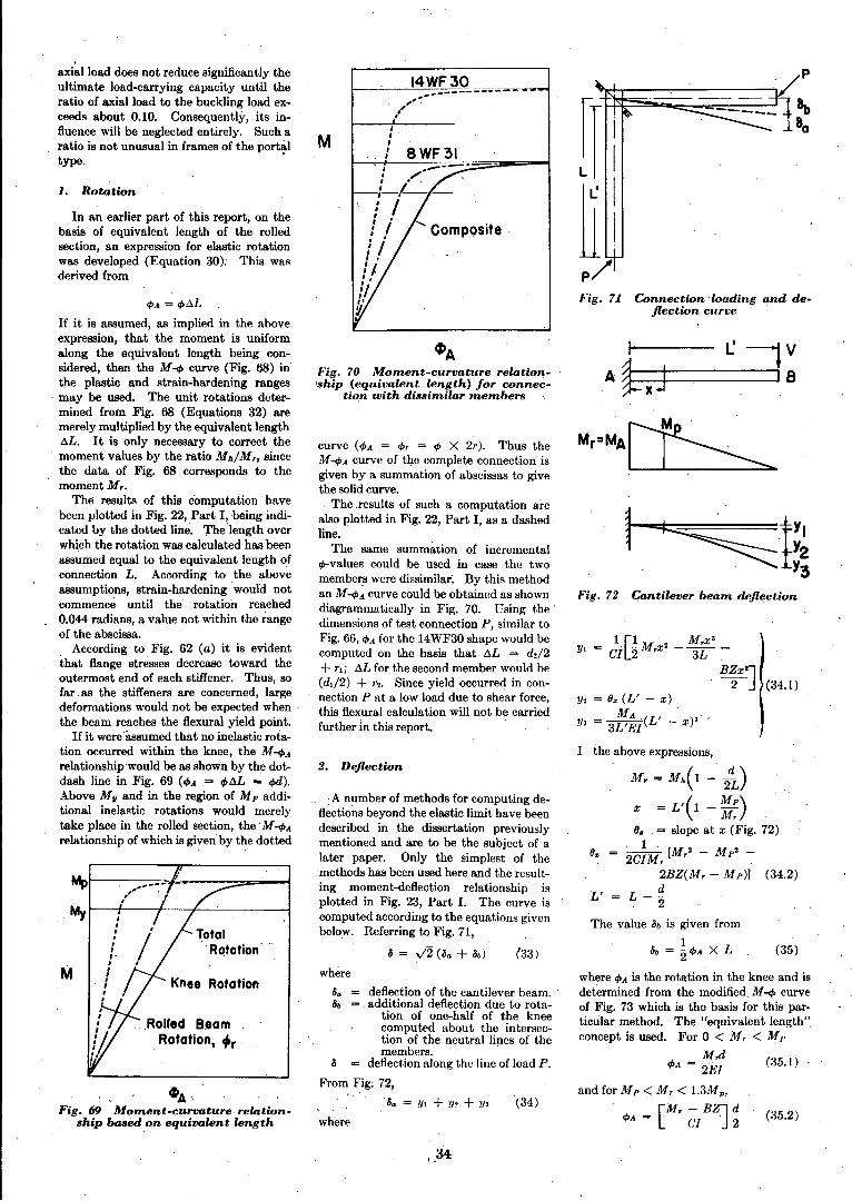
The same summation of incrementalet>-values could be used in case the twomembers were dissimilar~ By this methodan M-cP~ curve could be obtained as showndiagrammatically in Fig. 70. Using thedimensions of test connection P, similar toFig. 66, cPA for the 14WF30 shape would becomputed on the basis that aL = d./2+ T,; aL for the second member would be(di/2) + T2. Since yield occurred in connection P at a low load due to shear force,this flexural calculation will not be carriedfurther in this report.
~APig. 70 Moment-curvature relation'ship (equivalent length) for connec
tion with dissimilar members
where
M
., ,A number of methods for computing defl~ctions beyond the elastic limit have beendescribed in the dissertation previouslymentioned and are to be the subject of alater paper. Only the simplest of themethods has been used here and the resulting moment-deflection relationship isplotted in Fig. 23, Part 1. The curve iscomputed according to the equations givenbelow. Referring to Fig. 71,
8 = y2 (8a + 8b) (33)
Knee Rotation
.Rolled B.eamRotation, 4tr
M
aXi~1 load does not reduce significantly theultimate load-carrying capacity until theratio of axial load to the buckling load exceeds about 0.10. Consequently, its influence Will be neglected entirely. Such aratio is not unusual in frames of the port~1
type.
1. Rotation
~A·.Fig. 69 Moment-curvature· relation, ship based on equivalent length
In an earlier part of this report, on thebasis of equivalent length of the rolledsection, an expression for elastic rotationwas de:veloped (Equation 30); This wasderived from
cPA = cP aL
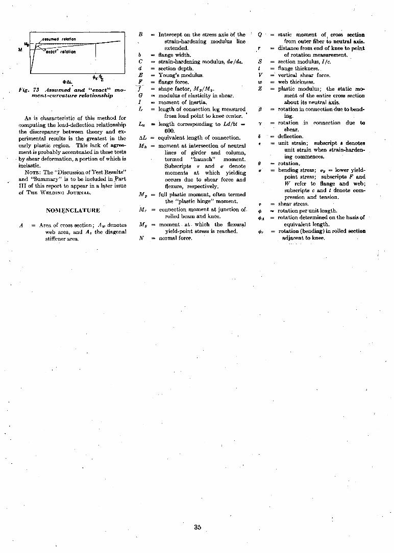
If it is assumed, as implied in the aboveexpression, that the moment is uniformalong the equivalent length being. considered, then the M-cP curve (Fig. 68) inthe plastic and strain-hardening rangesmay be used~ The unit rotations determined from Fig. 68 (Equations 32) aremerely multiplied by the equivalent lengthaL. It is only necessary to correct themoment values by the ratio Mh/M" sincethe data of Fig. 68 corresponds to themomentM,.
The results of this computation havebeen plotted in Fig. 22, Part I, being indicated by the dotted line. 'rhelength overwhich the rotation was calculated has beenassumed equal to the equivalent length ofconnectionL. According to the aboveassumptions, strain-hardening would notcommence until the rotation reached0.044 radians, a value not within the rangeof the abscissa.
According to Fig. 62 (a) it is evidentthat flange stresses decrease toward theoutermost end of each stiffener. Thus, sofar. as the stiffeners are concerned, largedeformations would not be expected whenthe beam reaches the flexural yield point.
If it were'assumed that no inelastic rotation occurred Within the knee, the M-cPArelationship would be as shown by the dotdash line in Fig. 69 .(cPA = cPaL = q,d).Above M u and in the region of M p additional inelastic rotations would merely
.take place in the rolled section, the· M-cPArelationship of which is given by the dotted
34I,
ssumed relaHon
"'Ioct" ~,'otion
f·ig. 73 Assumed and "exact" moment-curt1ature relationship
As is characteristic of this method foreomputing the load-deflection relationshipthe discrepancy between theory and experimental results is the greatest in theearly plastic region. This lack of agreement is probably accentuated in these tests
, by shear deformation, a portion of which isinelastic.
NOTE: The "Discussion of Test Results"and "Summary" is to be included in )?artIII of this report to appear in a lat.er issueof THE \VELDING JOURNAL.
l'"OM~NCLATURE
A Area of cross section; A,. denotesweb area, and A. the diagonalstiffener area.
B
bCdEFTGIL
N
Intercept on the stress axis of thestrain-hardening modulus 'lineextended.
flange width.strain-hardening modulus, d<TldE.section depth.Young's plodulus.flange force.shape factor, MpiMu.modulus of elasticity in shear.moment of inertia.length of connection leg measured
from load point to knee center.•
length corresponding to Ld/bt =
600.equivalent length of connection.
moment at intersection of neutrallines of girder and column,termed "haunch" moment.Subscripts .,. and <T denotemoments at which yielding,occurs due to shear force andflexure, respectively.
full plastic moment, often termedthe "plastic hinge" moment.
connection moment at junction of,rolled beam and knee.
moment at which the flexuralyield-point stress is reached.
normal force.
35
Q static moment of, cross sectionfrom outer fiber to neutral axis.
r distance from end of knee 'to pointof rotation measurement.
S section modulus, I Ie.t flange thickness.,V vertical shear force.w web thickness.Z plastic modulus; the static mo-
ment of the entire cross sectionabout its neutral axis.
fJ rotation in connection due to bend-ing.
'Y rotation in connection due toshear.
o = deflection.unit strain; subscript 8 denotes
unit strain when strain-hardening commences.
9 rotation.<T bending stress; <Tv = lower yield-
point stress; subscripts F andW refer to flange and web;subscripts e and t denote compression and tension.
.,. shear stress.tP rotation per unit length.tPA rotation determined on the basis of
equivalent length.tPr rotation (bending) in rolled section
adjacent to knee.
Welded Continuous Frames and Their ComponentsProgress Report No. 4
Connections for Welded Continuous PortalFrames
Part III-Discussion of Test Results and Conclusions
• Elastic and plastic strength of rigid frame connections,economies, connection design details and structural behavior
by Lynn S. Beedle, A. A.Topractsoglou and Bruce
G. Johnston
J. DISCUSSION OF TEST RESULTS
THE objectives of the investigation,outlined in Part I, form the basis forthe arrangement of this discussion of
test results. First,. the results are examined to see if the connections satisfythe requirements of elastic design. Arethe assumptions of present design practiceconsistent with safety? Secondly, it is ofinterest to observe the behavior beyondthe elastic limit and up to collapse in orderto evaluate the possibilities and limitationsof new concepts of plastic design andanalysis. These considerations cxeludethe possibility of failure due to fatigue.
1. Elastic Strain Distribntion inStraight Knees *
Connection P: The portions of Connection P outside the knee behaved accordingto the ordinary beam theory, Fig. :32t and:33. t At seetions close to the knee, within2 in. of the vertical stiffener, the stressdistributions become irregular due to enddisturbances, this being usual in the caseof any end conneetion 01' bearing support.
Lynn" S. Beedle is connected with the Fritz Engineering: Laboratory, Department of Civil Engineering and .l\'Iechanics, Lehigh University.Bethlehem, Pa., A. A. Topractsoglou is connectedwith the Department of Civil Engineering at theUniversity of Texas and Bruce G. Johnston i~Professor of Structural Engineering at the Uni\'-crsi ty of 1\'1 ichigan. .
* This work has been carried Oll t as a IHu't uf allinvestigation sponsored jointly by the 'VeldingHesearch Council and t.he Department. of theNavy with .funds furnished by the following:American InHtitute of Steel Construction,American Iron and Steel Institute, lnst,it,utc ofIteseareh, Lehigh University, COIUIIIIl HcsearellCouneil (Addsory), Offiee of Nnval ltcseareh(Cont.mct. No. 3(303), Bureau of Ships and t.heBureau of Yards and Docks.
However at sections of the beam andeolumn removed from the conncction adistance of half the depth of the section,the stresses were in reasonably good agreement with the computed values. As waspointed out in Part II the tensile stressesin the exterior beam' flange are transmitted to the knee by shear (Fig. 62 t).Such shear stresses must be consideredsince they may lead to excessive relativerotation between ends of connected members. In Co'nnection P, for example, themaximum web shear stress was larger thanthat at the critical section for bending.Later equations givc the required webthickness to prevent these undesirabledeformations due to shear force.
Figures 34 and 35 show that there arelocal strains that differ from the valuespredicted but the trend is to confirm theassumption for Type 7 eonnections thatbending moment deereases linearly froma maximum at the critical section wherethe knce joins the rolled section to zero atthe exterior corner. In the case of thebeam, as shown.in :Fig. 34, no correetionwas made for bending' in the outer flangesince SR-4 gages were mounted on hut oneside. From Fig. 21, noting the shape ofthe deformed top flange in the region ofthe knee, it is seen that the measuredstrains' are consistent with the deflectedshape. As expected, the stress is a maximum at the face of the column.
The theoretical distributions of stressshown in Figs. 32-35 take into aecountboth bending moment and direet stress,
* This treatment of clastic stnlH1'i distributionb only partially eomplete, and it jH expected that.further data will he presented in a separat.ereport.
t Figures 1 to 57, inelusivc, will be fOIl11<1 illPart I as published in t,hc .J Illy 1H!)l 'V ELDINC;.JOURNAIJ, pp. 359-1'5 t.o 384-s; FigH. 1')8 to 7:3,inclusive, are in Part II, August Ul51 \VELDINGJOUHNAL, pp. 397-s to 40.~~s. Figure .52 isincluded in this report as well as iII Part, I.
37
although the influenee of the ,latter isquite small. Sinee the lengths of members are short, additional moment due toeolumn deflection is negligible and has notbeen considered.
2. Elastic Strength of Connections
In this section will be discussed the behavior of the connections at loads in thevicinity of the yield point. The evidenceand influence of residual stresses and theformation of "yield lines" as revealed by
'mill scale wi II also be diseussed.
2.11. Shear Yield of Straight KneesWithont· Diagonal Stiffeners
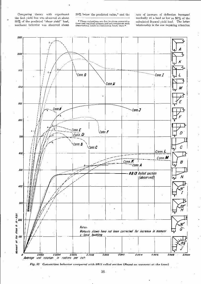
]i;quations have been developed in Section I, Part II, to prediet the moment atwhieh yielding of Type 7 connections due toshear force should commence and a comparison has bccn made with theoretictLlyield moments due to flexure. ConnectionP provided an opportunity to compare .theory with experimcnt, and :Fig. 19 of PartI contains, both theoretical and experimental curves. As is evident from thisfigure, nonlinear behavior of the connection commenced at a moment somewhatlower than the predicted moment at whiehyielding due to shear force should commence. Subsequent rotation was developed well beyond that which could betolerated in most engineering structures.The first yield line was observed at 311ill.-kips, nonlinear behavior was observedvisually from the plotted curve at 4!J:3in.-kips, and the maximum moment carried was 1150 ill.-kips. The theoretieal"shear yield" values are 724 in-kipsassuming a uniform dist.ribution of shearstress in the knee and 0;30 il1.-kips assuming;a nonuniform shea.r distribution (see ParI,TI of the pa.per). The predicted initialyield moment in Hexure is (195 in.-kips. ·
<>
Comparing theory with experimeiltthe first yield line was observed at about.50% of the predicted "shear yield!' load,nonlinear behavior was observed about
20% below the predicted value, * and the
* These reductions are due to stress concentrations and residual stresses and are consistent withobservations made in continuous beam tests. 35
rate of increase of deflection increasedmarkedly at a load as low as 50% of thecalculated flexural yield load. The latterrelationship is the one requiring attention
!J.pozo0.0018fl.0016
'" '" ..........·..· Conn.I
0. 00140.0012(J.OOfOo o.OtJ02 0. 0004 0.0006 (J. 0008Average untl rotation in radians per inch
500
1300.----~--,----,-----_,_---,_---_.---_,_---_,---___,_---__r---_.
I. // ...... , ~/T '-'\ A ..,
/2001------+
1
- -!-'---+-I/~'\..~~-+\---+----+---l-I-------jlu;
1000'1------++-,'/If---+---+--/---+-------'--j----t-,---+----+----,-----j-------; M
900 1------TI-/1/7/--;-'/!_~.--j-~----===l====F= __:::::::::-r---r---t-_Wi ;/r- .........COfi.V·1I r---......conn.J WI I ........, .; I.
800 I----_f_j'-i/I'+!----,,t-t-/ __.-=-""'....,... _'"._...._..._..._.._..._... +-.._..._....""'.. :-----t----+----j-----t------j F
I-_L+t-j1+-~j¥/C-I-·I2+-c~F~=___<·~+_~~-···~=;~:=-:!:+=Of},=.:..;.n.:..:.:....E=-----+_-··--'-+_-_+_--+__-___t_-_lf?0.'Ii ;: /1 ! """''''''''''' .-.-. 0 leonn. Fj' ! i /1. I ~.-[ "" Conn.
'/00 'I Ii . ~~/ .-' '",,=:'II !. 1 .' I ./~ '\ .-....... " L-JJ/' If/I I r L Conn. B \.111 IIJ/.. l-i I ~/~I/ \Conn. C 1-.. Ci I ij/;, I c L v
6001--I;-'IHjl--/ffiV++/~---+----+-----i---~I__-_-._---.+-._-.-==1:===..::=.-:::t.:=:-:~n==n:-~:==;; ~
! Ii #ir/ /~ .----;.-- c~;;K- -------- fE!!I!.,-__ BI Ii! ,Iiil ./-::....,;;:. -:":,;;;",,=:.,=... "'=:::::::::,conn. Ai ,'; iii ;:;;;;;;..... ..../ I I ~
i lily/1 i J..,.....;;;;;.... .:::....._...._....-;:./~.-:;;...::::::::..._//-://7"'-r-/-----t---t-- 88/1 Rolled secf~fn ~~Niii! Ii / '.(/ ;/ (observed/ ~.
II'i"/i /" ........ ~,iii fiji / /400 l----HiI+./iI--+--il--"-1h7'-----;;,L.--t-----t----+-----+----+-----+~~-___j
: I'i 1/ if I .~/ /// .16/"I N.lt f·, ../ "',/: '! I'· / ~ .!I ,'I 1>1u!l! j// ~JOOI---'-MhfH----f:i,f--+----:'---j-----'-+-----r----+-----+-----t-------r----j
!~ 1/1 zH~ilift i: // / c
.., ; 1/ /
~. I ~:roo 1-+
/
/j' -+-;,-jff//H.~'-':lli-'/'-:---+-----+---M-o-te-.s, _1 --'- --'-- ---' .L-__----' ~'
~ : Ii i Moments shown hare not been corrected lOr increase in moment~ ! it7';' . l : local bucklingrH-iV-I-../-D/'-f·-+------+-----I---'=..:..==;--=-=='-r------,r------r---.,---,~
~ ~y.
Fig.52 Connection behavior compared with 8B13 rolled section (Based on IIWllwnt at the knee)
38
since the computation of moments atwhich shear yielding commences is nota part of routine analysis procedures. Inspite of the large rotations, the connectiondid not develop the predicted flexuralyield strength of the weakest adjacentmember.
The assumption of uniform shear distribution in the knee web gives an approximate prediction of actual behavior, butthe assumption of nonuniform distributionof shear stress provides a much better indication of the load at which inelastic deformation of connections with unstiffenedwebs will commence.
Following the usual steps for proportioning ~t Type 7 connection the designerwould check the shear in the beam andcolumn; but it has been demonstratedhere that it is m08t important for hiin tocheck the shear in the knee web. t Tomake sure that the "shear" type of failuredoes not occur, the moment at which shearyield oceurs, M h(T)' must be equal to or
t It is assumed that the proportions are suchthat web buckling does not occur in the elasticrange of stress.
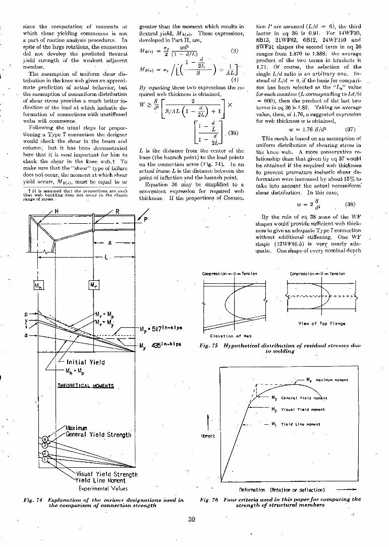
greater than the moment whieh results inflexural yield, M h(u). These expressions,developed in Part II, are,
U wd 2
Mh(T) = -f (1 _ dlL) (3)
1 - .!!:....
Mh(u) = Uy /C(---i~) + AlL}"(4)
By equating these two expressions the required web thickness is obtained,
W~'~[SIAL(l~~) +lJ X
[1 - ~J.(36)
1 - 2!-L is the distanee froin the center of theknee (the haunch point) to the load pointson the connention arms (Fig. 74). In anactual frame L is the distance between thepoint of inflection and the haunch poi~t.
Equation 36 may be simplified toaconvenient expression for required webthfckness. If the proportions o~ Connee._
tion P are assumed (Lid = 6), the thirdfaetor in eq 36 is 0.91. For 14WF30,8B13, 21WF82, 6B12, 24WFllO and8WF31 shapes the second term in eq 36ranges from 1.870 to 1.888; the averageproduct. of the two terms in brackets is1.71. Of course, the selection of thesingle Lid ratio is an arbitrary one. Instead of Lid = 6, if the basis for comparison has been selected as th~ "Lu" valuefor each member (L eorresponding to Ldlbt= 600), then the product of the last twoterms in eq 36 is 1.82. Taking an averagevalue, then, of 1.76, a suggested expressionfor web thiekness w is obtained,
w = 1.76 SId2 (37)
TIEs result is based on an assumption ofuniform distribution of shearing stress inthe knee web. A more eonservative relationship than that given by eq 37 wouldbe obtained if the required web thicknessto prevent premature inelastie shear deformation were inereased by about 15% totake into account the aetual nonuniform'shear distribution. In this case,
w = 2 ~ (38)d2
By the rule of eq 38 none of the WFshapes would"provide sufficient web thickness to give an adequate Type 7 eonnectionwithout additional stiffening. One WFshap'e (12WF16.5) is very, nearly adequate. One shape of every nominal depth
Fig. 75 Hypothetical distribution of residual stresses dueto welding .
p
¥I
a~-,-_
CarfJress ion .....0- T~nsion
Elevation of Web
~ression~O~Tension
View of Top Flange
THEORETICAL MOMENtSM4 Max I mum moment
lit} General Yield mom nt
Fig. 74 Explanation of the various designations used inthe comparison of connection strength
~mcimum
General Yield. Strength'
Visual Yield StrengthYield Line ~bment
Experimental Values
\bnent
Fig. 76
39
M2 Visual Ylald moment
Yield Line moment.
Ilefomation .(Rota~ion or deflection)
Four criteria used in this paper for comparing thestrength of structural members
has been checked by computation andseveral shapes within one series have alsobeen studied. The lighter members ineach nominal size more nearly meet theweb thickness requirement and would require the least amount of additionalstiffening.
Computations have also been mad!,) forAmerican Standard I shapes. For eachnominal depth the heaviest section th'eoretically has adequate web thickness withoutrequiring additional stiffening material.Most of the lighter sections in each serieshave insufficient ,web thickness.
Additional tests should be conductedspecifically for the purpose of checking thcvalidity ofeq 38 as a rule for specifyingthe required thickness of doubler plates ordiagonal stiffeners. However, since mostrolled shapes are deficient in web thicknessfor Type 7 connections, it is recommendedthat design rules require diagonal stiffenersor doubler plates. The 8B connectionuses the former detail. If the diagonalplate is objectionable, extra web thicknessmay be obt:1ined with doublers using eq38 as a gl.lide. Connections of this type
. were not tested in the program, althoughsuchstudies are planned.
In the case of Type 8B connection's,eq38 and the assumptions of Part II may beused to specify the required thickness ofdiagonal stiff'C~ers. In eq 29 the "effective" arca of the web was assumed t~:l)emade up of t'wo parts: the actual webarea, Aw = wd, and an equivalent stiffcner areai"~As', arrived at by assuming thestiffener IP.J1tehal JlIliformly distributedover the wcb plate. From eq 29,
As' ':= b,t,v2'
where
t, = stiffencr thickness.b, = total width of stiffener.
Since this equivalent stiffener area makesup the deficiency in web thickness, thcn
As' = (wr - wa)d
where Wr is the required w.eb thicknessaccording to eq 38 and Wa is the actual webthickness of the rolled shape and d is thesection depth. Equating the two expressions for As', the required ,thickness of'diagonal stiffener is given by II
t - (wr - wa)d (3lJ),'- b,v2
An examination of Fig. 20 shows thatthe eX"perimental defiection curve deviatesfrom a straight line at approximately thesame moment as' that of the rotationcurve (Fig. 19). This indicatcs that kneedcformations cause the nonlinear behavior at the low loads. This is dearfrom Fig. 21 as well. Figure 19 indicatesthat there .is no factor of safety againstyielding 'at a moment corresponding to aworking stress of 20 ksi. Thus, Connection P is "inadequate" from the point ofview of 'elastic design. As is evident fromFigs. 22 and 52 sufficient diagonal stiffening was provided in Connections A, K, L
and M to prevent serious shear deformation.. The photographs of the cori~~ctionsat failure (Figs. 26, 29) show that in spiteof the use of diagonal stiffeners, yield dueto shear force still occurred at high loads,but with a satisfactory margin of safetyfor elastic design.
2B. "Yield Lines" and Resid1wl Stress
Coating the connections with \vhitewashrevealed the fiaking of miiiscalc at yieldzones. "Yicld lines" werc obscrvedatloads between: 31 and 81 % of the calculated initial yield load as indicated on theexperimental curves (Figs. 22, 36, 37, 44).This yielding at less-than-calculated valuesis usually due to a combination of residualstresses and stress concentrations. Forthe larger built-up connections(B, N, G,H) the resultant increase in' m'easuredrotations or defiections due to formation
,of these first yield lines is slight indeed(Fig. 44). However,' in the remainingconnections where the' connection ,length-is"shorter, then formation' of the first,yield- line may be associated with thecommencement of nonlinearity of theload-deformation curve (Fig. 22). Theconsequences of nonlinear behavior atloads lower than the predicted yield pointare usually not serious in the case of members designed to resist flexural loads.However, when one considers columnaction, wherein yielding with a cori'esponding reduction in effective bending stiffnessaggravates buckling, the possible seriousness of residual stress becomes important.
All of the connections, a number ofwhich were built up by welding (i.e.,B, C, G, H, I), were tested in the asdelivered, as-welded condition. The observed yield line patterns indicate thatwelding introduced residual stress patternssomewhat similar to those formed due tocooling after rolling. Figure - 75' indicates schenuitically the possible distribution of residual stresses in web andflange mllterial at a cross section througha haunch fabricated by welding. In thetests, yield lines were observed at theedges of the compression flange and at thecenter of the tension flange.
2C. Yield 'Strength of Connection Type,
As in the caseOf most structural members'in bending, the transition from elastic to 'plastic behavior was very gradual in theseconnection tests; a well-defined yieldpoint was not observed (Fig. 52). Sincefunctions such as "initial yield load" and"yield strength" of the various connections are now to be compared, then definitecriteria will be adopted. Prior to describing the critcria available, the terminology will be defined:
(~) Moment-position of critical sectionalong the member:
10'[ h = "haunch" moment-the moment at intersection of extended neutral lines ofgirder and column (Fig.74).
40
ill r = "rolled scction" momentconnection moment atjunction of rolled beamand knee.
A[ = moment at any position.(b) Theoretical or computed m!iments
(subscripts h and I' have beenomitted): .
M i = "theoretical initial yield moment" of thc connectionfor a particular loadingcondition (Fig. 74).
10'[ y = "theoretical yield momentof the rolled section"the 'moment at which
, yield-point stress isreached at the end of thcrolled section.
,(c) Experimentally observed morr,wnts(subscripts h and I' omitted):
AI (I) = "yield line" moment-themoment at which thefirst yield line is observed(Fig. 74).
10'[(') = "visual yield" moment-, the moment at which the
plotted curve becomesnonlinear as observedvisually.
Jl[(3) = "general yield" moment(this criterion is defi~edbelow).
, Some of the available yicld strengthcriteria are summarized in the followingparagraphs. Not all of them have beenused in this paper.
(a) Yield Line Moment: The moment atfirst yielding, Jl[0), described above, is avalue recorded during the test, and isdetermined by careful examination of thetest member after each load increment(Fig. 76).
(b) Visual Yield lvloment: This has alsobeen described above and is-designated inFig. 76 as M(2). This is an approl'imatemethod dependent lIPon the scale to'which the curve is plotted and the judgment of the observer.
(c) General Yield Moment: M(3) isdetermined by the graphical methodshown in Fig. 76. Originally suggestedby one of the authors,33 it has beentermed the "limit of structural usefulness.'" It may be said to correspondapproximately to a point at which inelastie eonnection deformations would begin to affeet structural behavior elsewherein a eontinuous frame. Obviously it is anarbitrary deformation limitation.
(d) Scatter Band: After drawing theexperimental curve' to a large enoughscale to' indieate the seatter, the yield
,strength of the structure 01' member isdefined as the intersection with theexperimental curve of a line parallel tothe clastic part and offset by one-half theseatter band width. This method hasbeen used by others, but has not beenemployed in this paper. It is 'one of themost sensitive criteria.
(e) Slope Factor: Another method notoriginal, with the authors involves the
~ •.. '
r----------.-~-----------_,
1/3 Initial Slope
.\
t.brent
t-~-----r-~r----- General Yield Strength
(a)'
Ibnent
Yield
Yield
Deformationo Fig. 77 Additional yield st.rengtlt criteria
Deformation
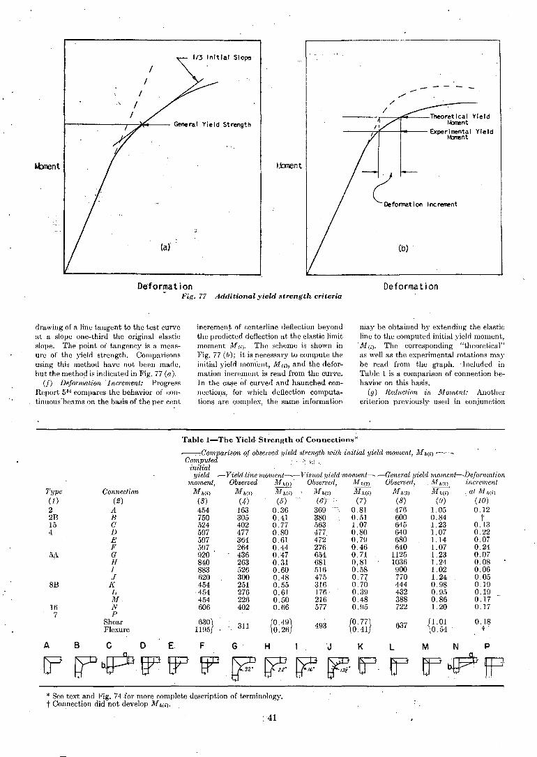
drawing of a line tangent to the test curveat a slope one-third the original elasticslope. The point of tangency is a measure of the yield strength. Comparisonsusing this method have not been made,but the method is indicated in Fig. 77 (a).
(f) Deformation -Increment: ProgressReport 534 compares the behavior of continuous'beams on the basis of the per cent
increment of centerline deflection beyondthe predicted deflection at the elastic limitmoment j~f(;). The scheme is shown inFig. 77 (/); it is necessary to compute theinitial yield mon;'ent, Mm, and the deformation increment is read from the curve.Tn the case ~f curved and haunched connections, for which deflection computations are complex, the same information
niay be obtained by extending the elasticline to the computed initial yield moment,
- jyI (i). The corresponding "theoretical"as well as the experimental rotations maybe read from the graph. .Included inTable 1 is a comparison of connection behavior on this basis.
(g) Reduction in Moment: Anothercriterion previously- used in conjunction
Table I-The Yield· Strength of Conneclions*
~Comparisonof observed yield strength with initial yield moment, lvIh(i)-~
Computed . ": ':,i '.initial . ,
yield ~Yield line moment~Visual yield 'moment~ -General yield 'fIwllwnt~Defonnation
moment, Observed M h(I) . Observed, jVfh(2) Observed, M h (3) inerementjyh(i) M h(I) lI{h('i) ll{h(2) lI{h(i) lI{h(3) Mh(i) : at lI{h(i)
(3) (4) (5) (6) :, (7) (8) (.9) (10)454 163 0.36 369'" 0.81 476 1.05 0.12750 305 0.41 380 0.51 600 0.84 t524 402 O. 77 563 1. 07 645 1. 23 O. 13597 477 0.80 477 0.80 640 1.07 0.22597 364 0.61 472 0.79 680 1.14 0.07597 264 0.44 276 0.46 640 1. 07 0.24920 436 0.47 654 0.71 1125 1.23 0.07840 263 0.31 681 0.81 1036 1.24 0.08883 526 0.60 516 0:58 900 1.02 0.06620 300 0.48 475 O.n 770 1.24 0.05454 251 0.55 316 0.70 444 0.98 0.19454 276 0.61 176 0.39 432 0.95 0.19454 226 0.50 216 0.48 388 0.86 0.17606 402 0.66 577 0.95 722 1.20 0.1716
7
8B
'l.'ype(1)22B154
Connection(2)
ABCDEFGH1J
KLMNP
Shear 630} 311 [0.49\ 493 {0.77} 637 fl.Ol 0.18Flexure 1195 '\O.26f 0.41 lO.54 t'
ABC 0 E F G H I 'J K L M N P
[? r;FbPtF tp ~ bF ~ ~ ~ If' ~ Ef'bP fP* See text and Fig. 74 for more complete description of terminology.t Connection did not develop M h(i).
:41
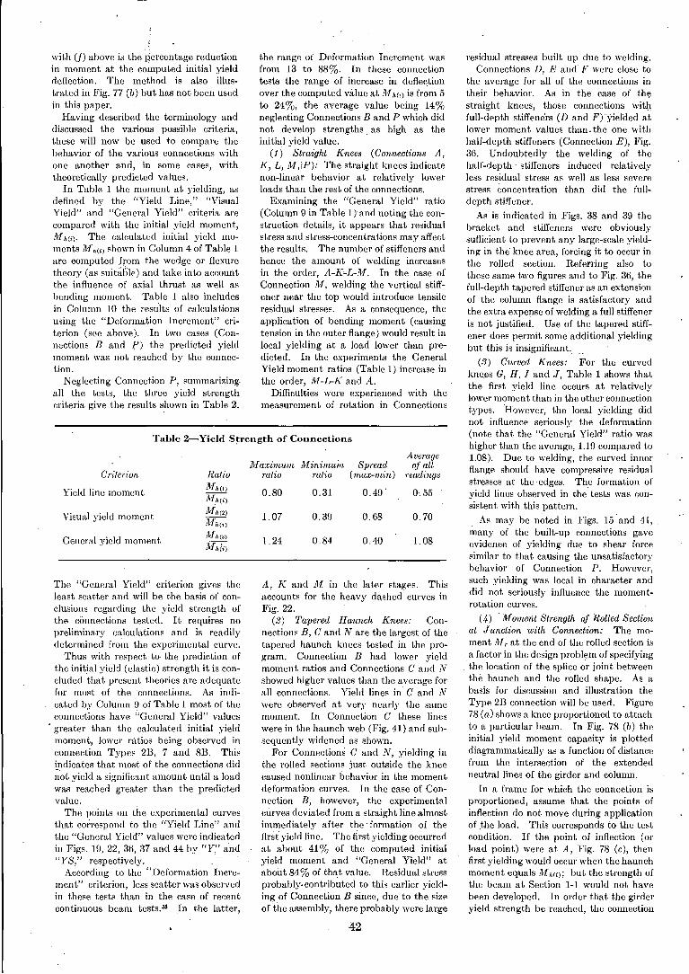
Table 2-Yield Strength of Connections
MininvuinAverage
Jv[aximwn Spread of allCriterion Ratio ratio ratio (max-min) readings
Yield line moment Jl1h(l)0.80 0.31 0.49 . 0.55
Mh(i)
Visual yield momen tiY[,,(2)
1.07 0.3n 0.68 0.70Mh(i)
General yield momentJ1[,,(:<)
1.24 0.84 0.40 1.08iYJ,.ii)
with (f) above is the percentage reductionin momcnt at the computed initial yielddcflection. The method is also illustrated in Fig. 77 (b) but has not been usedin this paper.
Having described the terminology anddiscusscd the various possible criteria,these will now be used to compare thebehavior of the various connections withone another and, in some cases, withtheoretically predicted values.
In Table 1 the moment at yielding, asdefined by the "Yield Line," "VisualYield" and "General Yield" criteria arecompared with the initial yield moment,!Ifh(i). The calculated initial yield moments M~h(i) shown in Column 4 of Table 1are computed .from the wedge or flexuretheory (as suitable) and take into accountthe influence of axial thrust as well asbending moment. Table 1 also includesin Column 10 the rcsults of calculationsusing the "Dcformation Increment" critcrion (sce abovc). In two cases (Connections Band l.') the predicted yieldmoment was not reached by the connection.
Neglceting Conneetion P, summarizing.all the tests, the thrce yield strengtheriteria give the results shown in Table 2.
The "General Yield" eriterion gives theleast scatter and will be the basis of conclusions regarding the yield strength ofthe connections tested. It requires nopreliminary calculations and is readilydetermined from the eJl:perimental curve.
Thus with respect to the prediction ofthe initial yield (elastie) strength it is concluded that present theories are adequatefor most of the connections. As indieated by Column n of Table 1 most of theconnections have "General Yield" values
. greater than the ealeulated initial yieldmoment, lower ratios being observed inconnection Types 213, 7 and 8B. Thisindicates that most of the connections did~'ot yield a significant amount until a loadwas reached greater than the predictedvalue.
The points on the experimental eurvesthat cOl:respond to the "Yield Line" andthe "General Yield" values were indicatedin Figs. 19, 22, 36, 37 and 44 by "Y" and"YS," respectively. ,
According to the "Deformation Increment" eriterion, less scatter was observedin these tests than in the case of recentcontinuous beam tests. 35 In the latter,
the range of Deformation Inerement wasfrom 13 to 88%. In these eonnectiontests the range of increase in deflee.tionover the computed value at]l,[h(i) is from 5to 24%, the average value being 14%neglecting Connections Band P which didnot develop strengths. as high as theinitial yield value.
(1) Straight Knees (Connections A,K, L, !If,:P): The straight knees indieatenon-linear behavior at relatively lowerloads than the rest of the connections.
Examining the "General Yield" ratio(Column 9 in Table 1) and noting the construction details, it appears that residualstress and stress-eoncentrations may affectthe results. The number of stiffeners andhence the amount of welding increasesin the order, A-K~L-M. In the case ofConnection M, welding the vertical stiffener near the top would introduce tensileresidual stresses. As a consequence, theapplication of bending moment (causingtension in the outer flange) would result inlocal yielding at a load lower than predicted. In the experiments the GeneralYield moment ratios (Table 1) increase inthe order, M-L-K and A.
Difficulties were experienced with themeasurement of rotation in Connections
A, K and M in the later stages. Thisaccounts for the heavy dashed curves inFig. 22.
(2) Tapered Haunch Knees: Con-nections B, C and N are the largest of thetapered haunch knees tested in the program. Connection B had lower yieldmoment ratios and Connections C and Nshowed higher values than the average forall connections. Yield lines in C and Nwere observed at very nearly the samemoment. In Connection C these lineswere in the haunch web (Fig. 41) and subsequently widened as shown.
For Connections C and N, yielding inthe rolled seetions just outside the kneecaused nonlinear behavior in the momentdeformation curves. In the case of Connection B, however, the experimentalcurves deviated from a straight line almostimmediately after the formation of theflrst' yicld line. Thetirst yielding occurredat about 41 % of the computed initialyield moment and "General Yield" atabout 84% of that value. Residual stressprobably, contributed to this earlier yielding of Connection B since, due to the sizeof the assembly, there probably were large
42
residual stresses built up due to welding.Connections D, E and F were close to
the average for all of the connections intheir behavior. As in the case of thestraight knees, those conneetions withfull-depth stiffene'rs (D and F) 'Yielded atlower moment values than. the one withhalf-depth stiffeners (Connection E), Fig.36. Undoubtedly the welding of thehalf-depth' stiffeners induced relativelyless residual stress as well as less scverestress concentration than did the fulldepth stiffener.
As is indicated in Figs. 38 and 39 thebracket and stiffeners were obviouslysufficient to prevent any large-scale yielding in the' knee area, forcing it to occur inthe rolled section. Referring also tothese same two figures and to Fig. 36, thefull-depth tapered stiffener as an extensionof the eolumn flange is satisfactory andthe extra expense of welding a full stiffeneris not justified. Use of the tapered stiffener does permit some additional yieldingbut this is insignificant..
(3) Curved Knees: For the curvedkne,es G, H, I and J, Table 1 shows thatthe first yield line oecurs at relativelylower moment than in the other connectiontypes. 'However, the local yielding didnot influence seriously the deformation(note that the "General Yield" ratio washigher than the average, 1.19 compared to1.08). Due to welding, the eurved innerflange should have eompressive residualstresses at the edges. The formation ofyield lines observed in the tests was consistent with this pattern.
As may be noted in Figs. 15'and 41,Tnany of the built-up connections gaveevidence of yielding due to shear forcesimilar to that causing the unsatisfactorybehavior of Connection P. However,such yielding was local in character anddid not seriously influence the momentrotation eurves.
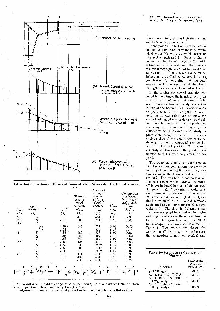
(4 ) Moment Strength of Rolled Sectionat Junction with Connection: The moment 111, at the end of the rolled section isa factor in the design problem of specifyingthe location of the splice or joint betweenthe haunch and the rolled shape. As abasis for discussion and illustration theType 213 conneetion will be used. Figure78 (a) shows a knee proportioned to attachto a particular beam. In Fig. 78 (b) theinitial yield moment capacity is plotteddiagrammatically as a function of distancefrom the intersection of the extendedneutral lines of the girder and column.
In a frame for which the connection isproportioned, assume that the points ofinflection do not move during applicationof the load. This corresponds to the testcondition. If the point of inflection (orload point) were at A, Fig. 78 (c), thenfirst yielding would occur when the haunchmoment equals ]1,[Mi); but the strength ofthe beam at Section I-I would not havebeen developcd. In order that the girderyield strength be reached, the connection
* L = distance from inflCGtion point to haunch point, H; a = distance from inflectionpoint to junction of beam and connection (Fig. 78).
t Adjusted for variation in matei'iaJ properties bet\\'cen haunch and rolled section.35.2
39.0
Yield pointstress in
tension, ksi
41.83n.l
Material
81313 flangesl/,_in. plate (B, C, G, J)3/s-in. plate (H, inner
flange only)1I.-in. plate (I, inncr
flange only) ,
Fig. 78 Rolled section momentstrength of Type 28 connections
Tahle.4-Strength of ConnectionMaterial
would have to yield and strain hardenuntil M h = M hly) as shown.
If the point of inflection were moved toposition B, Fig. 78 (d), then the knee wouldyield when M.h = illh(i), yield occurringat a section such as 2-2. Unless a plastichinge were developed at Section 2-2; withsubsequent strain-hardening, the theoretical yield strength could not be developedat Section 1-1. 'Only whcn the point ofinflection is at C (Fig. 78 (c» is therejustification for assuming that the connection will develop the elastic limitstrength at the end of the rolled section.
In the testing thc curved and the tapered-haunch knees thc length ofarmawasadjusted so that initial yielding sh~uldoecur more or less uniformly along thelength of the haunch. (This eornisponds
. to position Bof Fig. 78 (d).) A loadpoint at A was ruled out because, forstatic loads, good elastic design would callfor haunch depth to be proportionedaccording to the moment diagram, theeonnection being stressed as uniformly aspracticable along its length. It seemsobvious that if the conneetion were 'todevelop its yield strength at Section 1-1with thc load at position' B, it wouldcertainly do the same if the point of inflection were 'removed to point C or beyond.
The question then to be answered is:Did the various connections develop theinitial yield moment (Mrl "» at thc junetion between the haunch and thc rolledsection? The results ofa eompari,son onthis basis are shown in Table 3, Column 6(N is not included because of the unequalflange widths). The data in Column 6are obtained by dividing the observed"General Yield" moment (Column 4, defined previously) by the haunch momentat theoretical yielding of the rolled section,Column 5. The data in Column 5 hasalso been corrected for variation in material properties between the material used tofabricate the gaunches and the 81313rolled shape. The variation is sh~wn inTable 4. Two values are shown forConnection C, Table :3. This is becausethe conneetion is not symmetrical and
'C
(c) . M::ment diagrams for various loadi ng cood i tions
:" ..
.(b) M:rnent Capaci ty Curve(Yield Moments at eachcross-section)
(d) Moment diagrams withpoint of inflection atposition B
a
lied Section t.bmentsIMr )
2
Haunch t.bments(Mt, )
~==t====ft==~0~ == = = === = == =--=-4.......------- DC :
~"""I===;====i== = = = = == = = = == ==="I
(a) Connection and Loading
";lhIY)
t"t,lj)
Table 3-COlnparison of Observed General Yield Strength with Holled SectionYield
Computedhaunch Comparison
Observed moment neglectinggeneral at yield 1:njluence of
yield of rolled axial load,Con- moment, section, J1fhl,) Mh(3)
Type neclion Lla* i1fh'I') },thlY) i]fhlll ) A/,,' IY)
(1) (2) (3) (4) (5) (6) (7)2 A 1.13 476 454 1.05 0.97213 B 2.10 600 771t 0.78 0.66]5 C
a-a 2.04 645 791 0.82 0.73b-Ii 1.31 524 1.23 1. ]3
4 ]) 1.53 640 597 1. 07 0.97E 1.53 680 597 1.14 1.02F 1.53 640 597 1.07 0.97
5A' G .2.69 1125 976t 1.15 0.96H .2.50 1036 886t 1.17 0.95I 2.50 900 771t 1.17 0.83J 2.03 770 not 1.07 0.87
813 K 1.13 444 454 0.98 0.90L 1.13 432 454 0.95 0.88M 1.13 388 454 0.86 0.79
A B C D E F G H I J K L M N P
cp' [{bPW EP W ~~~.~:rr IJ ~b~~
43
2EI ESw - d3G ='d'G
Then the required web thickness, w, IS
given by
Replacing IF by [. (an assumption gn theunsafe side by a small amount),
dIdEI = wd'G + 2EI
w ~ 2.6 ~ (42)
This expression gives a web thiekness, w,which will provide adequate stiffness inthe elastie region. When measured rotations for Conneetion P ar~ ~ompared
with values eomputed aeeording to thisanalysis, agreement within 10% if observed.
Connection A (Type 2): The momentrotation eurve for Conneetion A is shown,in Fig. 22: The two theoretieal curves inthe elastie range are for the two differentassumptions made in Part iI of thepaper. The dot-dash eomputed elastieline takes into aeeount both shear andflexure; the dotted "equivalent length':line considers only flexure of an equivalentlength of rolled beam. It is evident fromthe rotation ealeulations of Part II thatboth the deformation due to shear and toflexure must be eonsidered when eomputing knee rotations.
Below 160 in.-kips Conneetion A deformed only 9% above the predietedvalue. Larger than predieted rotationswould be expeeted due to the absenee ofstiffeners to transmit the reaetion at there-entrant eorner of the eonneetion. Themeasured rotation is 38% greater thanthe theoretical value at a moment of 400in.-kips. It was noted previously thatrotation measurements for Connection Awere unreliable in the higher ranges.
Connections 'K, L, M' (Type 8B):Using Connection I.. as the basis for comparison, the expe;imental curve i~ the~Iastic range indicates rotations onlyabout 1% greater than that predicted considering both shear and flexure (dot-dashline in Fig. 22). Thus excellent agreemen t between theory and test was ob-tained. . '
The simplest computation of rotation,that based on "equivalent\l~hgth" as developedjn Part II, predict,s fotations thatare about 14% less than the observedvalues. Thus this connection type doesnot have sufficient effective web thicknessto prevent elastic rotations greater thanthose assumed by the simple theory. Itwould be of value to see how well thesimple theory (whieh neglects shear) agreewith ,tests of other sizes and shapes ofeross s,ection.
In Fig. 22 in. the inelastie region, two"theoretieal" moment-rotation curves aredrawn, one for uniform moment throughout the equivalent.length of the knee, theother based on the assumption that noinelastic rotation occurs within the knee(see P~rt II). The first assumption(dotted eurve) provides the best agreenient with exp'eriment over the greatestrange. At the end of the elastic portionand in the initial plastic range experimental values are greater than predictedby theory. Faetors;hmh' 'contrib~te tothis are residual st!'esses, stl:ess concen-
and for E = 30 X 106 psi, G = n.5 X 106
psi,
(41)
(40)<PA = <pd
where
The required web thiekness is obtained byequatilig expressiolis 40 and 41. Further,negleeting the influenee of the terms[1 - (d/L)Jand [1 - (d/2L)],
M~h.d =' M h + Mhd ,EI ,wd'G 2EIF
<p = ~; = ~/ (1 - -2~)'
From eqs 16 and 17 of Part II, the sum ofthe shear deformation, 1'7, and the bendingdeformation, {37, is given by
eonnection rotation above the value predicted on the basis of eomplete eontinuity.
3A. Straight Knees
ConnectionP (Type 7): In Fig. 19, deseribing the behavior of Conneetion P, the"computed elastie stiffness" consideringboth shear and flexure, is about 13%greater than the measured slope of the experimental eurve (solid line). The theoretieal moment-rotation eurves for the 8- and14-in. members are shown by broken lines.On the basis of "equivalent length" (seePart II) the elastic curve should lie betweenthese two cu~ves; it is shown in Fig. 19 asa long dashed line. The eonneetion failsby a factor of two to develop elastic stiffness equivalent to that assumed in elastiedesign; thus elsewhere in a structure ofwhich it' was a' part, stresses would behigher than the computed values,
At a moment. of about 600 ill.-kips, theeonnection commences to yield rapidly(due to shear in the knee panel) 'but atthe same time it corltinues to carry in-'ereased bending moment. The increasein load is due to the faet that (a) there isstrain hardening in the web and additionalload is required to cause yielding in thoseparts of the knee removed from the haunchpoint, and (b) the flanges provide restraint by bending as shown in Fig. 21
From the discussion in Part n, it isevident that a ealculation could be madeto obtain the required thiekness of webmaterial such that a Type 7 knee willmeet the stiffness requirements. Thisrequirement for knees joining rolledseetions of equal depth was that the rotation, <PA, measured over an equivalentlength (!:l.L = d) be no greater than thatgiven by the expression
3. Stiffness of Connect!ons in 'theEla~tic and Plastic Range
This section will cover the log,d-deformation a~pects of connection behavior,including' the moment-rotation and moment-deflection curves. Both the elastieand initial inelastie behavior will be eonsidered.
In Fig. 52 moment at the knee has beenplotted against the average unit rotation(total.rotation in the knee divided by theequivaiimt length). These are all eAllerimentally.' determined eurves. The solidline is the eurve deteJ'lnined from the eontrol-beam test (simply supported beiliUunder third-point loading).
This figure shows that all of the so.ealled "built-up" eonneetions exhibit anave:'age stiffness greater than that of therolled sec'tion (81313) in the elastic region.Only the straight knees (Types 2 and 813)are less rigid than the rolled section. Ithas b~en observed in tests of eontinuousbeams34 that residual stresses and stresseoncentnitions may cause an increase indefleetions above predieted values in theso-ealled elastie region; but the increasedd'lformations in the eonneetion tests are
. sCl,newhat greater than those usua:ll~
found in beam tests.The inereased rotations in the straight
knees will inerease the bending momentsand defle'etions elsewhere in any frame ofwhich th~ knee is a part. In a frame witha column height of 10 ft and a beam span of24 ft loaded at the third-points, using the81313 seetion and the experimental rotation of Conneetio~ I.. at the theoretiealinitial· yield moment, the defleetion wasfound to ,be about 10% greater than predieted. ' This was due to the inerease in
yielding would occur sooner at one end ofthe connection than at the other.
The following observations are madewith respect to the data in Column 6 ofTable 3.
(a) Neg,rly all of the conneetions developed "General Yield" strengths greater'than a moment eorresponding to initialyield at the end of the eonnection.
(b) The straight knees had lowerratio.s than most of the other connections.
(c) Connection B yielded at 78% of theload eorresponding to rolled section yield.Based on Section a-a, Connection Cyielded at 82% of the load eorresponding'to rolled section yield. Under the symmetrical loading system used Section b-bwould be the critical eross section of theconneetion.
(d) As a group, the curved knees givethe best performance.
In Column 7 of Table 3 the connectionshave been compared neglecting the influenee of additional direct stress due toaxial load in the computation of M hey). Inall but two cases signifieant yielding oceUlTed at loads lower than the initial
,yield load in flexure at the jUliction ofrolled beam and connection.
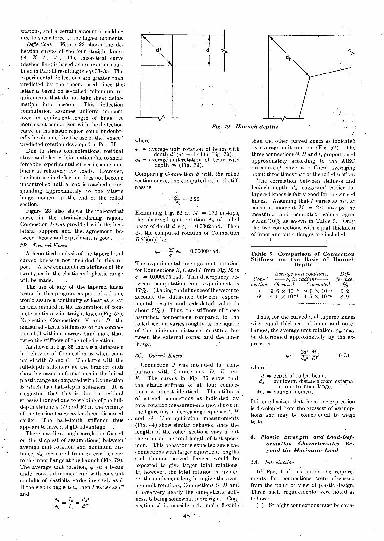
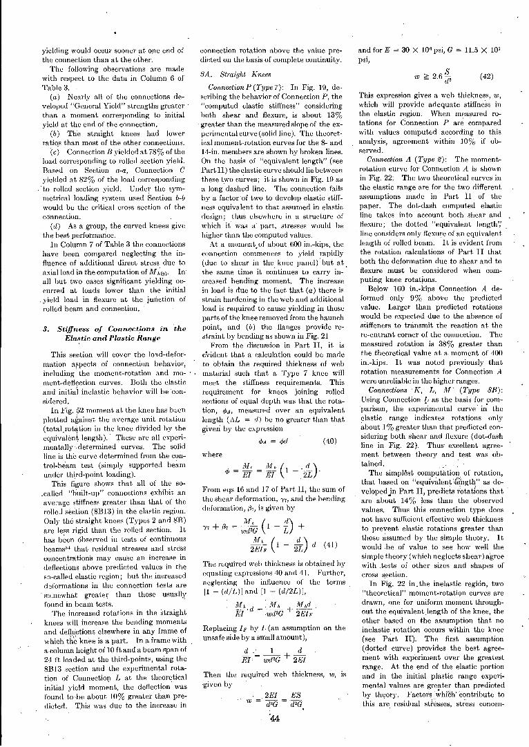
Fig. 79 Haunch dept.hs
Dif-ference,
%6.28.9
Average unit rotations,~-cP, in radians-~
Observed Computed9.6 X 10-5 9.0 X 10⁻⁵
4.9 X 10⁻⁵ 4.5 X 10⁻⁵
than the oth,er curved knees as indicatedby average unit rotation (Fig. 52). Thethree connections G, H and I, proportionedapproximately according to the AISCprocedures,l have a' stiffness averagingabout three times that of the rolled section.
The correlation between stiffness andhaunch depth, d h, suggested earlier fortapered knees is fairly good for the'eurvedknees. .Assuming that I varies as d h', atconstf~t moment 111 = 270 in-kips themeasured and computed values agreewithili'jO% as shown in Table 5. Onlythe two connections with 'equal thicknessof inner and outer flanges are included.
,;
where
d= depth of rolled beam.dh = minimum distance from external
corner to inner flange.JlI h = hauneh moment.
I t is emphasized that the above expressionis developed from the grossest of assumptions and may be coincidental to thesetests. .
Connection
JG
Table 5-Comparison of ConnectionStiffness on the Basis of Haunch
Depth
2d' JlI hcP~ = d." iff( (43)
Thus, for the curved and tapered kneeswith equal thickness of inner and outerflanges, the average unit rotation, cPh, maybe determined approximately -by the expression
4A. Introduction
In Part I of this paper the requirements for eonnections were discussedfrom the point of view of plastic design.Three such requirements were noted asfollows:
(1) Straight connections must be eapa-
4. Plastic Stre~gth and Load-Deformation Characteristics Be.'Yond the Maximum Load
dd'
';',rf!!- = 222.cP, .
Examining Fig. 52 at 111 = 270 in.-kips,the observed unit rotation cPa of rolledbeam of depth d is cPa = 0.0002 rad. ThencPb, the computed rotation of ConnectionB:;~J-i'Q.4!~ be
cP· .cPb = ¢; cPa = 0.00009 rad.
The experimental average unit rotationfor Connections B, C and P.from Fig. 52 iscPb = 0.000075 rad. This discrepancy between computation and experiment is17%. (Taking the influenceofthe \'Ceb intoaccount the difference between experimental results and calculated value isabout 5%.) Thus, the stiffness of thesehaunched connections compared to therolled section varies roughly as the squa;'eof the minimum distance measUl'ed between the external corner a;ld the innerflange.
where
cPt = average unit rotation of beam withdepthd' (d' = 1.414d, Fig. 79).
cf>, average unit 'rotation of beam withdepth:d,; (Fig. 79).
Comparing 'Connection B with the rolledsection cUl've, the computed ratio of stiffness is
SC~ Curved Knees
Connection J was intended for 'eomparison with Connections D, E andF. The curves in Fig. 36 show thatthe elastic stiffness of all four connections is almost identical. The stiffnessof curved connections as indicated bytotal rotation measurements (not shown inthe figures) is in decreasing sequence I, Hand G. The qeflection measurements(Fig. 44) show similar behavior since thelengths of the rolled sections vary aboutthe same as the total length of. test specimen. This behavior is expected since theconnections with larger equivalent lengths.and thinner. curved flanges would beexpected to give larger total rotations.If, however, the total rotation is dividedby the equivalent length to .give the average unit rotations, Connect'ions G, Hand1 have.-very nearly the same;elastic stiffness, G being som~whatmore"rigid. Cop.:neetion J is considerably more flexible
trations, and a certain amount of yieldingdue to shear force at the higher moments.
Deflections: FigUl'e 23 shows the deflection eUl'ves of the foUl' straight knees(A, K, L, Ai). The theoretical curve(dashed line) is based on assumptions outlined in Part II resulting in eqs 33-35. Theexperimental deflections a1"e greater thanpredicted by the theory used since thelatter is based on so-called minimum re-·quirements that do not take shear deformation into account. This ideflectioncomputation assumes uniform momentover an equivalent length of knee. Amore exact comparison with the deflectioncurve in the elastic region could undoubtedly be obtained by the use of the "exact"predicted rotation developed in Part II.
Due to 'stress concentrations, residualstress and plastic deformation due to shearforce the experimental curves become nonlinear at relatively low loads. However,the increase in deflection does not becomeuncontrolled until a load is reached corresponding approximately to the plastichinge moment at the end of the rolledsection.
Figure 23 also shows the' theoretiealeurve in the strain-hardening region.Connection L was provided with the bestlateral support and the. agreement between theory and experiment is good.
3B. Tapered Knees
Atheoretical analysis of the tapered andeUl'ved knees is not included in this report. A few comments on stiffness of thetwo types in the elastic and plastic rangewill be made. •
The use of any of·' the tapered kneestested in this program as part of a framewould assure a continuity at least as greatas that implicd in the assumption of complete continuity in straight knees (Fig. 52).Neglecting Connections Nand D, themeasUl'ed elastie stiffnesses of the connections fall within a narrow band more thantwice the stiffness of the rolled seetion.
As shown in Fig. 36 there is It differencein behavior of Connection E .when compared with D and P. The latter with thefull-depth stiffeners at the bracket endsshow increased deformations in the initialplastic range as compared with ConnectionE which has half-depth stiffeners. It issuggested that this is due to residualstresses induced due to welding of the fulldepth stiffeners (D and P) in the vicinitvof the tension flange as has been discussedearlier. The half-depth stiffener th'usappears to have a slight advantage.
There may 13e a rough correlation (basedon the simplest of assumptions) between'average unit rotation and minimum distance, d h ,. measured from external cornerto the inner flange at the haunch (Fig. 79).The average unit rotation, cP, of a beamunder constant moment and with constantmodulus of elasticity varies inversely as I.If the web is neglected, then I varies as d'and
45 .
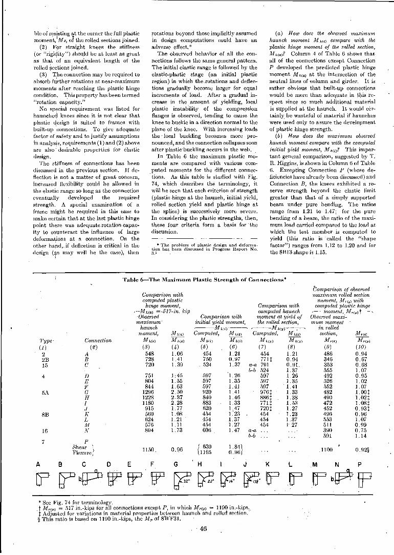
ble of fl:sjsting ~t the corner the full plasticmoment,'Mp, of the rolled sections joined.
'(2) For straight knees the stiffness(or "rigicjity") should be at least as greatas that of an equivalent length of therolled ~ections joined.
(3) T,he connection may be required toabsorb further rotations at near-maximummoments after reaching the plastic hingecondition. This property has been termed"rotation' capacity."
No special requirement was listed forhaunchect knees since it is not clear thatplastic design is suited to frames withbuilt-up connections. To give adequatefactor of safety and to justify assumptionsin analysis, requirements (1) and (2) aboveare also J desirable properties for elasticdesign.
The stiffness of connections has beendiscussed in the previous section. If deflection is not a matter of great concern,inci'eased flexibility could be allowed inthe elastic range so long as the connectioneventually developed the requiredstrength. A special examination of aframe might be required in this case tomake certain that at the last plastic hingepoint there was adequate rotation capacity to counteract the influence of largedeformations at a connection. On theother hand" if deflection is critical in thedesign (tS may well be the case), then
rotations beyond those implicitly assumedin design computations could have anadverse effect. *
The observed behavior of all the connections follows the same general pattern.The initial elastic range is followed by theelastic-plastic stage (an initial plasticregion) in which the .rotations and deflections gradually become larger for equalincrements of load. After a gradual increase in the amount of yielding, localplastic instability of the compressionflanges is observed, tending to cause theknee to buckle in a direction normal to theplane of the knee. With increasing loadsthe local buckling becomes more pronounced, and the connection collapses soonafter plastic' buckling occurs in the web.
In Table 6 the maximum plastic moments are compared with various computed moments for the different connections. As this table is studied with Fig.74, which describes the terminology, itwill be seen that each criterion of strength(plastic hinge at the haunch, initial yield,rolled section yield and plastic hinge atthe splice) is successively more severe.In considering the plastic strengths, then,these four criteria form a basis for' thediscussion.
* The problem of plastic design and deformation has been discussed in Progress Report No.3.'
(a) How does the observed maximumhaunch moment Al h(.) compare with theplastic hinge moment of the rolled section,Mh(a)? Column 4 of Table 6 shows thatall of the connections except ConnectionP developed the predicted plastic hingemoment M heal at the intersection of theneutral lines of 'Column and girder. It israther obvious that built-up connectionswould be more than adequate in this respect since so much additional materialis supplied at the haunch. It would certainly be wasteful of material if hauncheswere used only to assure the developmentof plastic hinge strength.
(b) How does the maxirmlm observedhaunch moment compare with the computedinitial yield moment, M hei)? This important general comparison, suggested by T.R. Higgins, is shown in Column 6 of Table6. Excepting Connection P (whose deficiencies have already been discussed) andConnection B, the knees exhibited a reserve strength beyond the elastic limitgreater than that of a simply supportedbeam under pure bending. The ratiosrange from 1.21 to 1.47; for the purebending of a beam, the ratio of the maxi
'mum load carried compared to the load atwhich the test member is computed toyield (this ratio is called the "shapefactor") ranges from 1.12 to 1.20 and forthe 8B13 shape is 1.15.
Table 6....,..The Maximum Plastic Strength of Connections*
1100 0.92§
M,(.)M,(p)
(10)0.940.670.681.070.951.021. 07LOOt1.02t1.08t0.93t0.961. 070.990.751.14
Comparison withcomputed plastic
hinge moment,~Mh(a) =·517-in. kip
Observed Comparison withmaximum' initial yield moment,
haunch ~-AI"(i)---~
moment, Af,,(.) Compvted, M h(.)
Type' Connection M h(.) Jlfh(a) l11 Mi ) Mh(i)
(1) (2) (8) (4) (5) (6)
2 A 548 1.06 454 1.212B B 728 1.41 750 0.971.5 C 720 1.39 .524 1.37
4 D 751 1 :45 597 1.26E 804 1.55 597 1.35,P 844 1. 63 597 1.41
5A G 1296 2.50 920 1.41H 1228 2.37 840 1.46I 1180 2.28 883 1.33.J 915 1.77 620 1.47
8B J( 560 1.08 454 1:23L 624 1. 21 454 1. 37M 576 1.11 454 1.27
16 N 894 1. 73 606 1.47
7 PShear I 1150. 0.96 { 630 1.84;1.Flexure] 119.5 0.96[
Comparison withcomputed haunch
moment at yield ofthe rolled section,
~Afh(Y)-~~
Computed, M· h (.)
111 hey) Mh(y)
(7) (8)454 1. 21771t 0.94
a-a 791 0.91.b-b 524 1.37
59'7 1.26597 1.35.597 1. 41976t 1. 33886t 1. 38771t 1..53720t 1. 27454 1.234.54 1.37454 1'.27
Comparison of observedmaximum rolled section
moment, M'<4l withcomputed plastic hinge~-inoment, Af,(p)t-~
Observed maxi-mum moment
in rolledsection,
ll1d .)
(9)4863463.53555492526552482490472452496.553511390591
ABC D E F G H I J K L .M N P
[? k?' bP WIP §P bJG bF ~ ~ l~lJEF bP ff3* See Fig. 74 for terminology.
.t Mr(p) = 517 in.-kips for all connections except P, in which Mr(p) = 1190 in.-kips..t Adjusted for variations in material properties between haunch and rolled section.'§ This.ratio is based on 1190 in.-kips, the M p of 8WF3L
. 46
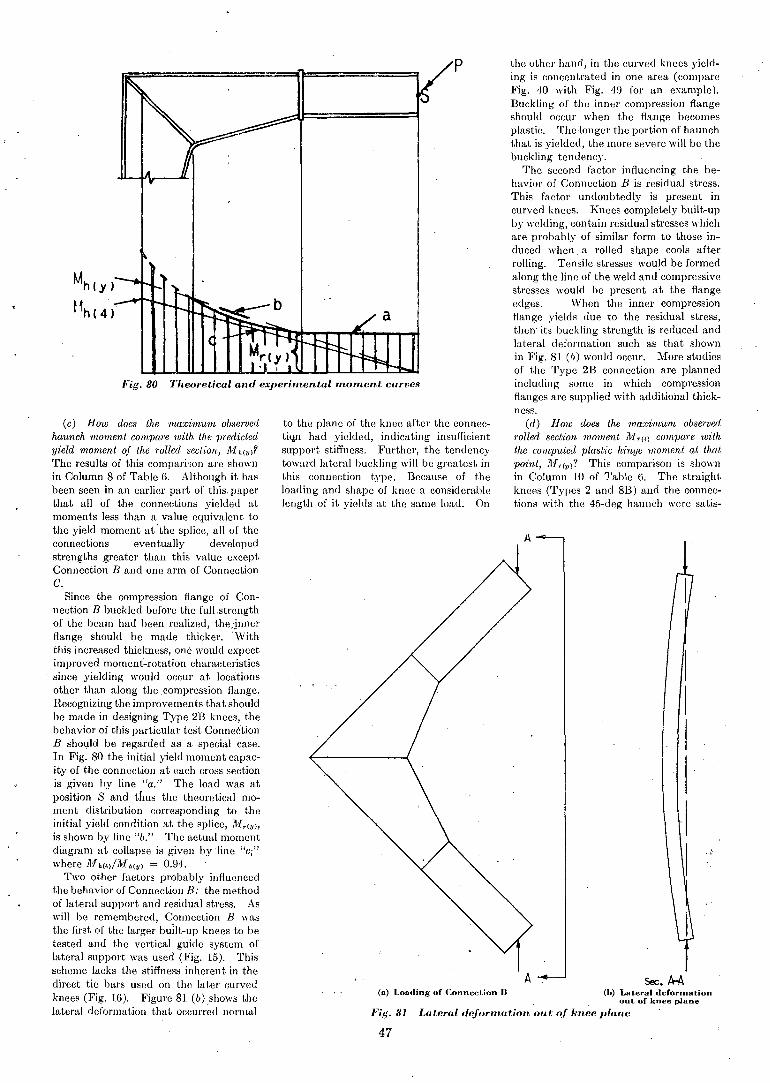
I
I II I
I·1
I
Sec.A-A
A
A
the othcr hand, in the curved knees yielding is conccntrated in one area (compareFig. 40 with Fig. 49 for an example).Buckling of the inner compression flangeshould occur when the flange becomesplastie. The-longer the portion of haunchthat is yielded, the more severe will be thebuckling tendency.
Thc second factor influencing the behavior of Connection B is residual stress.This factor undoubtcdly is present incurved knees. Knees completely built-upby welding, contain residual stresses whichare probably of similar form to those induced when a rolled shape cools afterrolling. Tensile stresses would be formedalong the linc of the weld and compressivestresses would be present at the flangeedges. When the inner compressionflange yields due to the residual stress,then- its buckling strength is reduced andlateral deformation such as that shownin Fig. 81 (Ii) would occur. More studiesof the Type 2B connection are plannedincluding some in which compressionflanges are supplied with additional thickness.
(d) How does the maximum observedrolled section moment M~T(4) compare withthe computed plastic hinge moment at thatpoint, Mr(p)? This comparison is shownin Column JO of Table 6. The straightknees (Types 2 and 8B) and the connections with the 45-deg haunch were satis-
p
(a) Loading of Connection R (h) Lateral defortnationou t of knee plane
Fig. 81 La/.eral deformation out; of knee plane
to the plane of the knee after the conneeti~ had yiclded, indicating insufficientsupport stiffness. Furthcr, the tendeneytoward latcral buckling will bc greatest inthis eonnection typc. Bccause of theloading and shape of kncc a considerableIcngth of it yiclds at thc samc load. On
Pig. 80 Theoretical and experimental moment curves
(c) How docs the maximwn observedhaunch moment compare with the predictedyield moment of the rolled section, M h(u)?
The results of this comparison arc shownin Column 8 of Table 6. Although it hasbeen seen in an earlicr part of this. papcrthat all of the conncctions yicldcd atmomcnts less than a value cquivalcnt tothe yicld moment at' the splice, all of thcconnections cventually devclopcdstrengths greatcr than this valuc cxceptConncction Band onc arm of ConnectionC.
Sincc the compression flange of Connection B buekled before the full.strengthof the beam had been realized, the.·!nnerflange should be made thieker.\Viththis increased thickness, one would expectimproved moment~rotation characteristicssince yielding would occur at locationsother than along the _compression flange.Recognizing the improvements that shouldbe made in designing Type 2B knees, thebehavior of this particular test Conne6"tionB should be regarded as a special case.In Fig. 80 the initial yield moment capacity of the connection at each cross sectionis given by line "a." The load was atposition S and thus the theoretical moment distribution corresponding to theinitial yield condition at the spliee, 1I1,(u),
is shown by line "b." The actual momentdiagram at collapse is given byline "Ci"
where M h(4)/Mh(u) = 0.94.Two other factors probably influenced
the behavior of Connection B: the methodof lateral support and residual stress. Aswill be remembered, Connection B wasthe first of the larger built-up knees to betested and the vertical guide system oflateral support was used (Fig. 15). Thisscheme lacks the stiffness inhercnt in thedircct tie bars used on the latcr curvedknces (Fig. 16). Figure 81 (b) shows thelateral deformation that occUlT~d normal
47
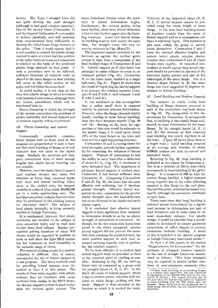
factory. The Type 7 straight knee didnot quite develop .the yield strength(although it had good rotation capacity).One of the curved knees (Connection J)and the tapered Connection B were unableto deform plastically and still maintaintheir cross-sectional form sufficien tly todevelop the rolled beam hinge moment atthe splice. Thus it would appear that itis not possible to extend the plastic designmethod to such an extent that thc positionof the splice betWeen beam and connectionis selected on the basis of the predictedplastic hinge moment at that point. Ifsuch a procedure were to .be followed,sufficient thickness of material must beplaced in the inner flanges so that yieldingwill occur in the rolled section at thesplice and not within the knee itself.
As noted earlier, it is not clear at thistime that plastic design is suited to frameswith haunched connections, although thereare certain possibilities which will bementioned later on.
Before discussing. in detail the strengthof the various connections the. problems ofplastic instability and lateral support andof rotation capacity will k>e mentioned.
4B. Plastic Instability and LateralSupport
Commercially .available eross-sec-tional shapes such as those used in thisprogram are proportioned in such a manner that local buckling of flange or of webelements does not occur in the elasticrange, Similarly the members and complete connections were of short enoughlengths that elastic lateral buckling wasnot possible.. However, once the elastic limit is passed
(and residual stresses may cause thissituation 'at lower than expected loads)both local and lateral buckling followsince, in the yielded area, the tangentmodulus is reduced from about 30,000,000psi to a value approaching zero. Thefact that immediate collapse does not occurmay be attributed to "the yielding processfor structural steel: 31 The subject oflocal piastic instabilit}· is bBing currentlystudied at Lehigh University.
It is emphasized, .however, that plastl:cinstability was involved in the collapse ofevery connection tested, and in most casesbrought about final collapse. Similar con-'nections joining m!,mbers of other WFshapes would be expected to perform atleast as well since ,the light 81313 sectionhas low resistance to local. instability inthe inelastic range of stress.
The onset of yielding results in a markedreduction in stiffness; this, of course,necessitates the use of lateral support ina test program. The three methods usedfor providing lateral support were described in Pad I of this paper. Theresults of these tests, together with others,indicate that for members with crosssectional form similar to the 81313 shape,the flex-1mr support system is'much betterthan the vertical guide system. The
latter introduces friction when the tendency to lateral deformation begins.Furthermore, the vertical guides, beingmore flexible, allow more lateral deflectionwhich in turn further aggravates the buckling tendency. Local and lateral inelastic buckling start at very nearly the sarnetime. For straight knees this may beseen by reference to Figs. 30 and 31.
The improved support provided by theflex-bars as against the vertical guidesystem is clear from a comparison of thefinal buckled shape of Connections BandG. Later~1 support on G (flex-bars) wasadequate to cause collapse to occur in anS-shaped pattern (Fig. 46); ConnectionB, on the other hand, buckled in a singlehalf-wave, Fig. 81. Figure 52 shows thatthe result of improving the lateraJ supportis to increase the rotation capacity (compare D and.E with P, and compare A andK with Land M).
It was confirmed in this investigationthat a rather small force is requiredinitially to prevent sidewise deformation.However, when the flange elements bucklelocally, tending to cause lateral buckling,then this force increases rapidly (Figs. 30and 43). Bracing at the knee for c<lllnections of this type would be adequate inthe plastic range if it could caITy about10% of the total thrust on the knee andwere tied to a rigid supporting structure.
Conneetions JY[ and L, having about thesame strengths, provide further opportunity for examining the influence of lateralsupport. 'Whereas 1.1 eommenees to losethe ability to earry load after a defleetionof about 0.7 in. (Fig. 23), L eontinues toearry increased load. The importance ofadequate lateral support is evident sinceConnection L has shorter stiffeners thanConnection 111. Comparing ConnectionsP and D, Fig. 36, the latter has the mosteffective web stiffening, but P developsgreater strength. Effective lateral support is the only explanation for the greaterplastic strength since the load-deflectioncurves are identical in the elastic and earlyplastic region.
It is concluded that effective lateralsupport is more significant than variationin fabrication details in so far as plasticstrength of connections is concerned. Although, for the two connection types compared in the above paragraph, inferiorlateral support did not prevent the members from reaehing the predieted load, themore positive support in each case inereased carrying capacity and, in particular, the rotation eapacity.
To be most effective it is evident thatlateral support must be provided as closeto the expected point of yielding as possible. Referring to Fig. 52, the built-upknees may be compared as a group withthe straight knees (A, K, L, M). In thelatter the point of lateral support, whichis the re-entrant corner, coincides with thepoint at which flange yielding will firstoeeur. Suppo~t is thus provided at thelocation at which it is needed the most.
48
However, in the haunched. knees (B, G,H, I, J) lateral support e~1lI10t be provided along the whole length of innerflange. In the tests loeal b~ckling oceursat loeations remote from ,the point oflateral support and as a eon~equen«e eollapse is relatively rapid. This behavior isalso seen within the group of eurvedknees themselves. Connections I and Jhave the shortest effective' lengths andposse~s better plastic rotati~n characteristics than connections G arid H whichbuckle more rapidly. In h~unched connections it would appear that lateral support should be provided at t~e. end of thehaunches (splice points) anc! aJso at themid-Iength.of the inner flange. Use of achannel shape formed to -'fit the innerflange has been suggested to" improve resistance to lateral buckling: 'i
4-C. Local Buckling and Rotation Capacity
The moment at which . visible local'buckling of flange elements.: oecurred ineach of the connections has':heen shownin Fig. 52. The designatiq~ of two observations for Connect.ion No' correspondsfirst, to buckling of the column flange and,second, to loeal deformation "of the beamflange. In the straight kne~s' (A,K, Land M) the moment at first observedlocal buckling was nearly id~ntical in allthe tests. (Figure 22 shows these data toa larger seale.) Local buckj!rtg occurredat an average unit rotation' of about0.00033 radians pC!.' inch i~;, curved andhaunched knees.
Referring to Fig. 22, loeal~uckling isindicated at two places for COnnection L.One is at a moment ~t 520 in.~kips whichcorresponds to local buckling:'of the girderflange. At a moment of 588 in.-kips theeoJumn flange bueklecl, a higher momentbeing required due to the extra stiffeningsupplied to this flange by the end plate.Beyond this point, rotations increased veryrapidly although the conneetion eontinuedto carry load.
These tests show that loeal buckling isfollowed almost immediately: by a significant increase in deformation per unit ofload increment and in some, cases by almost immediate collapse.. For plastiedesign, it would be essential that a specification be developed for proper geometricproportions of rolled shapes to preventpremature inelastic buckling. A studyof this is included in the cun:ent programat Lehigh University mentioned earlier. *
. In Part I of this report, in the section"Requirements for Connections" the importance of adequate rotation capacityin the case of straight knees- was emphasized as follows: "The knee (straight)may be required to absorb further rotations at near-maximum moments after
* Plast,ic local huckling of outstanding flangesis a problem that apparently has' not concernedinvestigators in the British Isles and on the eootinent of Europe. The reason ·pj>obabl.v lies inthe fact that the I-shape has inherent resistanceto local buckling that the WF'shape does notpossess. Since the-latter is not iri: general use inthose areas, -the problem has not' r-equired seriousattention.
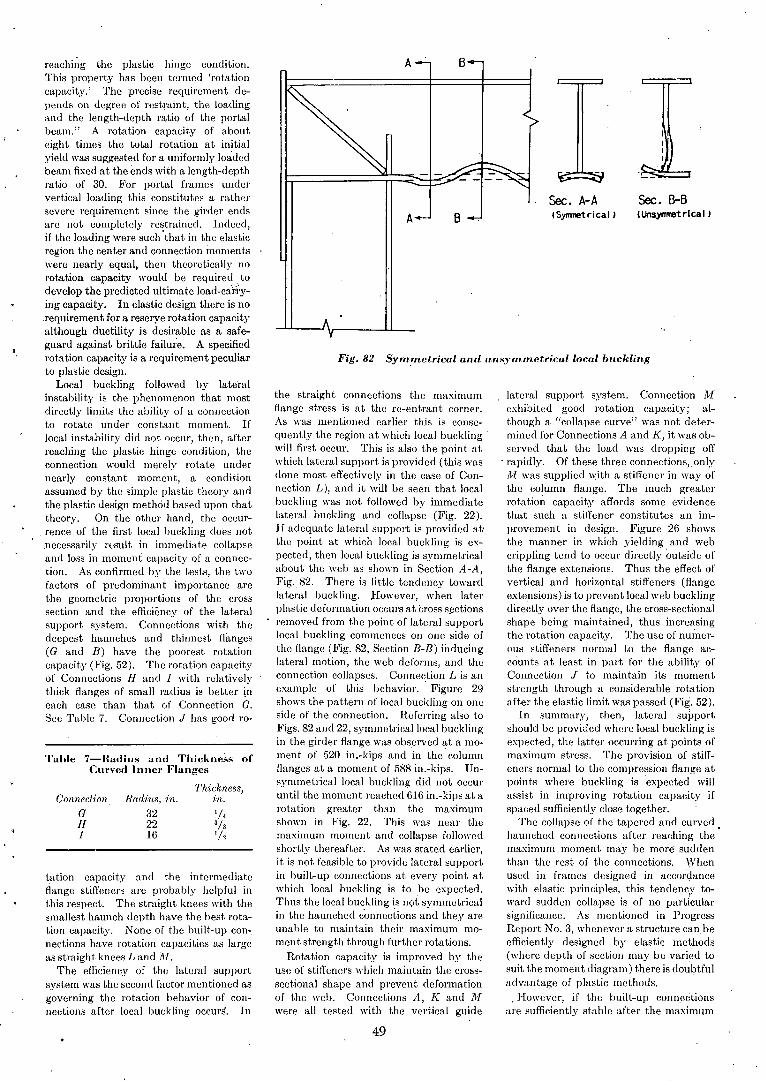
Sec. B-B(Unsymmetrical'
Sec. A-A(Synmetrical'
lateral support system. Connection 1.1exhibited good rotation capacity; although a "eollapse curve" was not determined for Connections A and K, it was observed that the load was dropping off
. rapidly. Of these three connections,. only111 was supplied with a stiffener in way ofthe column flange. The much greaterrotation capacity affords some evidencethat such a stiffener constitutes an improvement in design. Figure 26 showsthe manner in whieh yielding and webcrippling tend to oceur directly outside ofthe flange extensions. Thus the effect ofvertical and horizontal stiffeners (flangeextensions) isto prevent loeal web bueklingdireetly over the flange, the eross-sectionalshape being maintained, thus inereasingthe rotation eapacity. The use of numerous stiffeners normal to the flange aeeounts at least in part for the ability ofConnection J to maintain its momentstrength through a considerable rotationafter the elastic limit was passed (Fig. 52).
In summary, then, lateral sUI)portshould be provided where local buckling isexpected, the latter oceurring at points ofmaximum stress. The provision of stiffeners normal to the compression flange atpoints where buekling· is expected willassist in improving rotation capacity ifspaeed suffieiently elose together.
The eollapse of the tapered and eurvedhaunehed connections after reaching the'maximum momen t .may be more' suddenthan the rest of the conneetions. Whenused in frames designed in aceordaneewith elastic principles, this tendeney toward sudden collapse is of no partieularsignifieanee. As mentioned in ProgressReport No.3, whenever a strueture eanbeefficiently designed by elastic methods(where depth of seetion may be varied tosuit the moment diagram) there is doul;>tfuladvantage of plastic methods.,However, if the built-up connections
are suffieiently stable after the maximum
BA
the straight connections the maximumflange stress is at the re-entrant corner.As was mentioned earlier this is consequently the region at which local bucklingwill first occur. This is also the point atwhich lateral support is provided (this wasdone most effectively in the ease of Connection L), and it will be seen that loealbuckling was not followed by immediatelateral buekling and eollapse (Fig. 22).If adequate lateral support is provided at·the point at which local buckling is expeeted, then loeal buckling is symmetricalabout the web as shown in Section A-A,Fig. 82. There is little tendeney towardlateral buckling. ,However, when laterplastic deformation occurs at cross sectionsremoved from the point of lateral supportlocal buckling commences on one side ofthe flange (Fig. 82, Seetion B-B) inducinglateral motion, the web deforms, and theconnection collapses. Connection L is anexample of this behavior. Figure 29shows the pattern of loeal buckling on oneside of the connection. Referring also toFigs. 82 and 22, symmetrieallocal bucklingin the girder flange was observed at a moment of 520 in.-kips and 'in the' columnflanges at a moment of 588 in.-kips. Unsymmetrical loeal buckling did not oeeuruntil the moment reached 616 in.-kips at arotation greater than the maximumshown in Fig. 22. This was near themaximum moment and collapse followedshortly thereafter. As was stated earlier,it is not feasible to provide lateral supportin built-up connections at every point atwhich local buckling is to be expected.Thus the local buckling is not symmetricalin the haunched c'onnections and they areunable to maintain their maximum moment strength through further rotations.
Rotation capaeity is improved by theUSe of stiffeners whieh maintain the crosssectional shape and prevent deformationof the web. Connections A, K and 1.1were all tested with the vertical guide
Fig.82 Symmetrical ancl u.nsymmetricallocal bu.ckling
Radius, in.322216
GHI
Conneclion
Tahle 7-Radius and Thickness ofCurved Inncr Flanges
Thickness,in.
tation capacity and the intermediateflange stiffeners are probably helpful inthis respect. The straight knees with thesmallest haunch depth have the best rotation capaeity. None of the built-up connections have rotation capacities as largeas stmight knees Land 111.
The effieieney of the lateral supportsystem was the second faetor mentioned asgoverning the rotation bebavior of connections after local buckling occurs. In
reachi~g the plastic hinge condition.This property has been termed 'rotationcapacity.' The precisc requirement depends on degree of restraint, the loadingand the length-depth ratio of the portalbeam." A rotation capacity of abouteight times the total rotation at initialyield was suggested for a uniformly loadedbeam fixed at the ends with a length-depthratio of 30. For portal frames undervertical loading this constitutes a rathersevere requirement since the girder endsare not completely restrained. Indeed,if the loading were such 'that in the elasticregion the center and connection momentswere nearly equal, then theoretically norotation capacity would be required todevelop the predicted ultimate load-carl'ying capacity. In elastic design there is norequirement for a reserye rotation capacityalthough ductility is desirable as a safeguard against brittle failure. A specifiedrotation capacity is a requirement peculiarto plastic design. .
Local buckling followed by lateralinstability is the phenomenon that mostdirectly limits the ability of a connectionto rotate under constant moment. Iflocal instability did not occur, then, afterreaching the plastie hinge condition, theconnection would merely rotate undernearly constant moment, a conditionassumed by the simple plastie theory andthe plastic deBign methcid based upon thattheory. On the other hand, the occurrenee of the first loeal buckling does not.necessarily rvsult in immediate collapseand loss in moment capacity of a connection. As confirmed by the tests, the twofaetors of predominant importance arethe geometrie proportions of the crossseetion and the efficiency of the lateralsupport system. Connections with thedeepest haunches and thinnest f1illlges(G and B) have the poorest rotationcapaeity (Fig. 52). The rotation eapacityof Connections H and I with relativelythick flanges of small radius is better ineach ease than that of Conneetion G.See Table 7. Conneetion J has good 1'0-
"
49
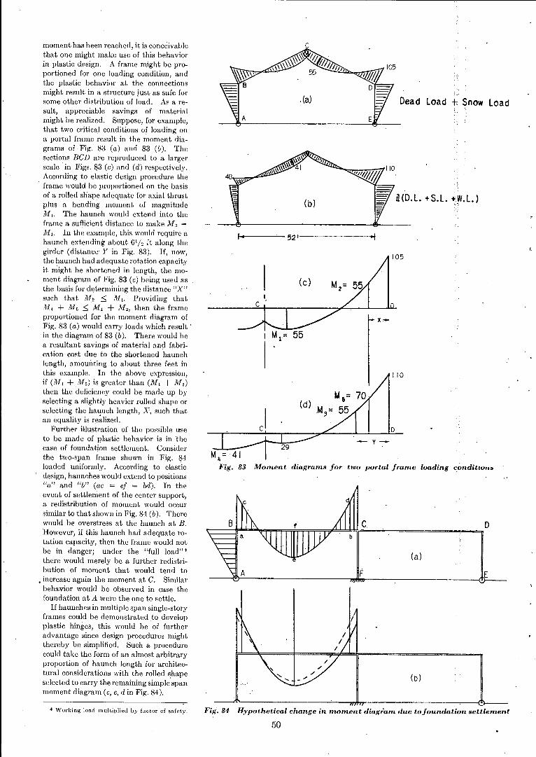
,';,
(.'
Dead load + Snow load
iHD.l. +S.l. ~Y'.l.)
110
D
y-29
Moment diagrams for two portal frame loading conditw....
tA s= 70(d)M
3= 55
1-0'40-----'-- 521--------I"i
105
M = 41IIFig. 83
moment has been reached, it is conceivablethat one might make use of this behaviorin plastic design. A frame might be proportioned for one loading condition, andthe plastic behavior at the connectionsmight result in a structure just as safe forsome other distribution of load. As a result, appreciable savings of materialmight be realized. Suppose, for example,that two critical conditions of loading ona portal frame result in the moment diagrams of Fig. 83 (a) and 83 (II). Thesections BCD are reproduced to a largerscale in Figs. $3 (e) and (d) respectively.According to elastic design procedure the
. frame would be proportioned on the basisof a rolled shape adequate for axial thrustplus a bending moment of magnitudeM,. The haunch would extend into theframe a sufficient distance to make M 3 =
llf,. In the example, this would require ahaunch extending about 6'12 ft along thegirder (distance Y in Fig. 83). If, now,the haunch had adequate rotation capacityit might be shortened in length, the moment diagram of Fig. 83 (c) being used asthe basis for determining the distance "X"such that M 2 ::::; M,. Providing thatM. + M 5 ::::; M, + M 2 , then the frameproportioned for the moment diagram ofFig. 83 (a) would carry loads which result·in the diagram of 83 (b). There would bea resultant savings' of material and fabrication cost due to the shortened haunchlength, amounting to about three feet inthis example. In the above expression,if (M. +M5 ) is greater than (M, + M 2 )
then the deficiency could be made up byselecting a slightly heavier rolled shape orselecting the haunch length, X, such thatan equality is re~lized.
Further illustration of the possible useto be made of plastic behavior is in thecase of foundation settlement. Considerthe two-span frame shown in Fig. 84loaded uniformly. According to elastic
, design, haunches would extend to positions"a" and "ii" (ae = ef = bd). In theevent of settlement of the center support,a redistribution of moment would occursimilar to that shown in Fig. 84 (b). Therewould be overstress at the haunch at B.However, if this haunch had adequate rotation capacity, then the frame would notbe in danger; under the "full load" *there would merely be a further redistribution of moment that would tend to
• increase again the moment at C. Similarbehavior would be observed in case thefoundation at A were the one to settle.
If haunches in multiple span single-storyframes could be demonstrated to developplastic hinges, this would be of furtheradvantage since design procedures mightthereby be simplified. Such a procedurecould take the form of an almost arbitraryproportion of haunch length for architec~
tural considerations with the rolled shapeselected to carry the remaining simple'spanmoment diagram (c, e, d in Fig. 84).
* Working load multiplied by factor of safet.y. Fig.84 llypothe/;ical change in moment diagram due tofoundation settlement
50
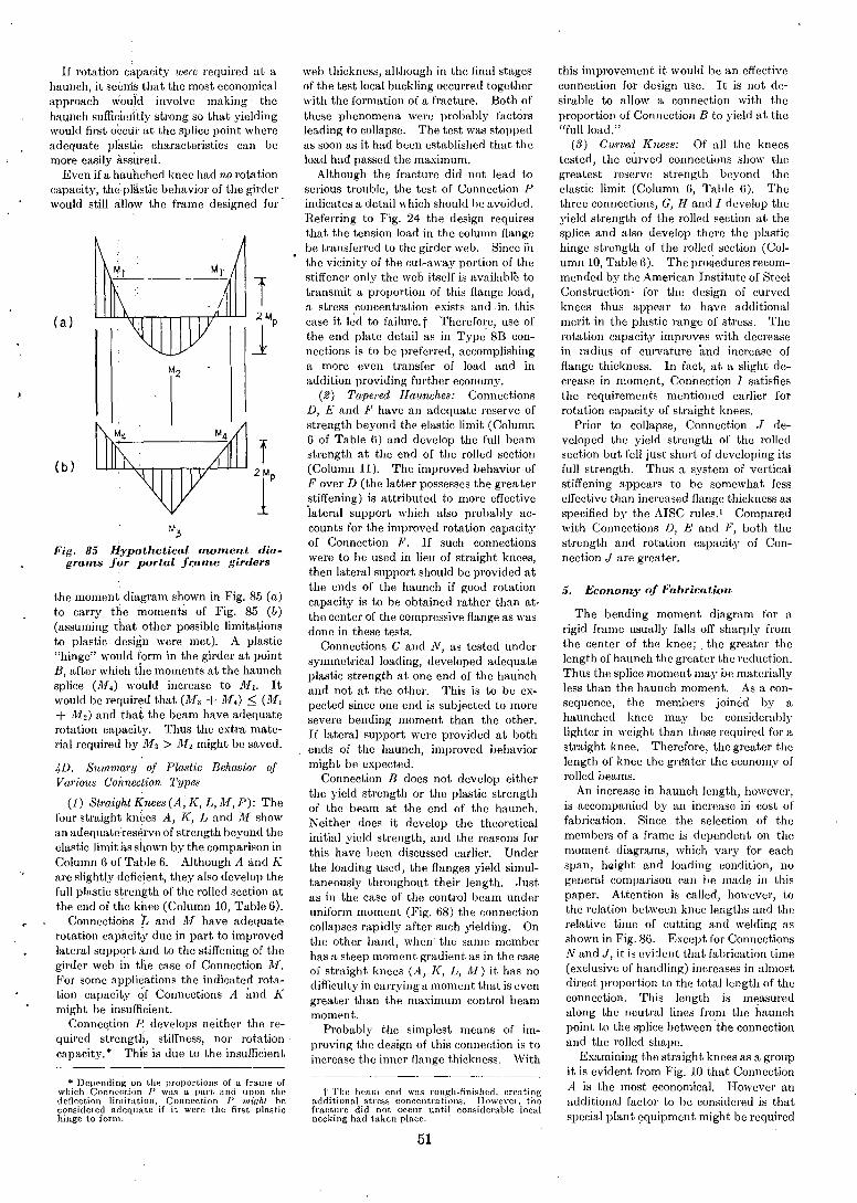
* Depending on the proportions of a frame ofwhich Conneotion P was a part, and upon thedeflection limitation, Connection P mioht beconsidered adequate if it were the first plastichinge to f DrIll.
If rotation capacity were required at ahaunch, it seimls that the most economicalapproach would involve making thehaunch sufficiierttly strong so that yieldingwould first occur at the splice point whereadequate plastic characteristics can bemore easily assiIred.
Even if a hauhched knee had no rotationcapacity, the plastic behavior of the girderwould still allow the frame designed for'
the moment diagram shown in JCig. 85 (a)to carry the moments of Fig. 85 (b)(assuming that other possible limitationsto plastic design were met). A plastic"hinge" would form in the girder at pointB, after which the moments at the haunchsplice (M.) would increase to M,. Itwould be required that (11'1 3 + M.) ::; (M,+ M 2 ) and that the beam have adequaterotation capacity. Thus the extra material required by M 3 > M 2 might be saved.
4D. Summary of Plastic Behavior ofVarious Connection Types
5. Economy of Fabrication
The bending moment diagram for arigid frame usually falls off shall)ly fromthe center of the knee; . the greater thelength of haunch the greater the reduction.Thus the splice moment may be materiallyless than the haunch moment. As a consequenee, the members joined by ahaunched knee may be considerablylighter in weight than those required for astraight knee. Therefore, the greater thelength of knee the grl!ater the economy ofrolled beams.
An increase in haunch length, however,is accompanied by an increase iri cost offabrication. Since the selection of themembers of a frame is dependent on themoment diagrams, which vary for eachspan, hlilight and loading condition, nogeneral comparison can be made in thispaper. Attention is called, however, tothe relation between knee lengths and therelative time of cutting and welding asshown in JCig. 86. Except for ConneetionsNand J, it is evident that fabrication time(exclusive of handling) increases in almostdireet proportion to the total length of theconnection. This length is measuredalong thc neutral lines from the haunchpoint to the splice between the connectionand the rolled shape.
Examining the straight knees as a groupit is evident from Fig. 10 that ConnectionA is the most economical. However anadditional factor to be eonsidered is thatspecial plant equipment might be required
this improvement it would be an effectiveconnection for design use. It is not dcsirable to allow a eonnection with theproportion of Conncction B to yield at the"full load."
(3) Curved Knees: Of all the kneestested, the curved connections show thcgreatest rcserve strength beyond theelastic limit (Column 6, Table 6). Thethree connections, G, H and I develop theyield strength of the rolled section at thesplice and also develop there the plastichinge strength of the rolled section (Column 10, Table 6). Thc prociedures recommended by the American Institute of SteelConstruction! for the design of curv'edknces thus appear to have additionalmerit in the plastic range of stress. Therotation capacity improves with decreasein radius of curvature and increase offlange thickness. In fact, at a slight decrease in moment, Connection I satisfiesthe requirements mentioned earlier forrotation capacity of straight knees.
Prior to collapse, Connection J developed the yield strength of the rolledsection but fell just short of developing itsfull strength. Thus a system of vertiealstiffening appears to be somewhat lesseffective than increased flangc thickness asspecified by the AISC rules. I Comparedwith Connections D, E and Ji', both thestrength and rotation capacity of Connection J are greater.
t The beam end was rough-finished, creatingadditional stress concentrations. However, thefracture did not OCCHr until considerable localnecking had taken place. .
web thickness, although in the final stagesof the test local buckling occurred togetherwith the formation of a fracture. Both ofthese phenomena were probably factorsleading to collapse. The test was stoppedas soon as it had been established that theload had passed the maximum.
Although the fracture did not lead toserious trouble, the test of Connection Pindicates a detail which should be avoided.Referring to Fig. 24 the design requiresthat the tension load in the column flangebe transferred to the girder web. Since inthe vicinity of the cut-away portion of thestiffener only the web itself is available totransmit a proportion of this flange load,a stress concentration exists and in. thiscase it led to failure. t Therefore, use ofthe end plate detail as in Type' 813 connections is to be preferrcd, accomplishinga more even transfer of load and inaddition providing further economy.
(2) Tapered Haunches: ConnectionsD, E and F have an adequate reserve ofstrength beyond the elastic limit (Column6 of Table 6) and develop the full beamstrength at the end of the rolled seetion(Column 11). The improved behavior ofF over D (the latter possesses the grea tel'stiffening) is attributed to more effeetive'lateral support which also probably aeeounts for the improved rotation capacityof Conneetion F. If such eonneetionswere to be used in lieu of straight knees,then lateral support should be provided atthe ends of the hauneh if good rotationeapacity is to be obtained rather than at·the eenter of the eompressive flange as wasdone in these tests.
Conneetions C and N, as tested undersymmetrieal loading, developed adequateplastie strength at one end of the haunehand not at the other. This is to be expeeted since one cnd is subjeeted to moresevere bending moment than the other.If lateral support were provided at bothends of the haunch, improved behaviormight be ell.l)ected.
Connection B does not develop eitherthe yield strength or the plastic strengthof the beam at the end of the haunch.Neither does it develop the theoreticalinitial yield strength, and the reasons forthis have been discussed earlier. Underthe loading used, the flanges yield simultaneously throughout their length. ,Justas in the case of the control beam underuniform moment (Fig. 68) the connectioncollapses rapidly after such yielding. Onthe other hand, when' the same memberhas a steep momen t gradient as in the caseof straight knees (A, K, L, AI) it has nodifficulty in carrying a moment that is evengreater than the maximum control beammoment.
Probably the simplest means of improving the design of this connection is toincrease the inner flange thickness. With
f
TM3
Hypothetical moment diafor portal fr.ame girders
(1) Straight Knees (A, K, L, M, P): Thefour straight kn~es A, K, Land M showan adequate:res~rveof strength beyond theelastic limit as shown by the comparison inColumn 6 of Table 6. Although A and Kare slightly deficient, they also develop thefull plastic stren~th of the rolled section atthe end of the krtee (Column 10, Table 6).
Connections Land JJI have adequaterotation capacity due in part to improvedlateral support and to the stiffening of thegirder web in the case of Connection M.For some applications the indicated rotation capacity ~f Connections A and Kmight be insufficient.
Connec.tion P. develops neither the required strength, stiffness, nor rotation'capacity. * Thi's is due to the insufficient
Fig. 85grams
(b)
(al
51
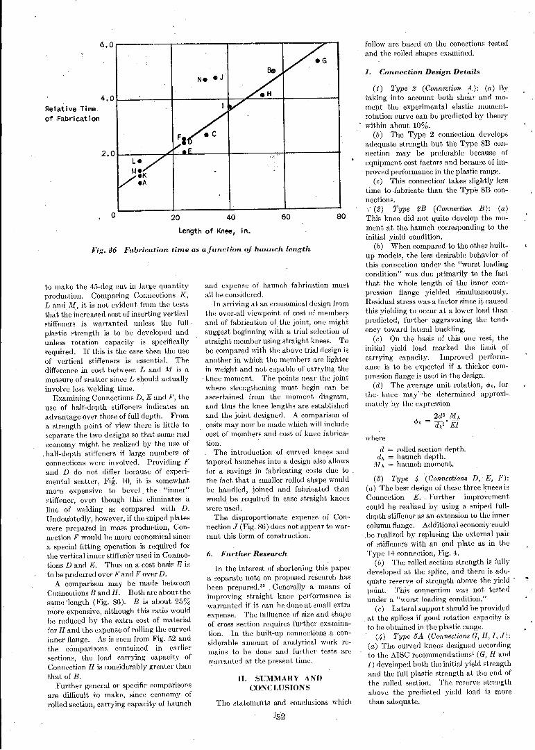
(3) Type .4 (Connections D, E, F):(a) The best design of these three knees isConnection E. Further improvementcould be realized by using a sniped fuJldepth stiffener as an extension to the innercolumn flange. Additional econoniycouldbe re,alized by replacing the external pairof stiffeners with an end plate as in theType 14 connection, Fig. 4.
(b) The rolled section strength is fullydeveloped at the splice, and there is adequate reserve of strength above the yieldpoint. This eOljnection was not testedunder a "worst loading conditiori."
(c) Lateral support should be providedat the splices if good rotation capacity isto be obtained in the plastic range.
(.4) Type sA (Connections G, H, I, J):(a) The curved knees designed aeeordingto the AISC reeommendations' (G, Hand1) developed both the initial yield strengthand the fuJI plastic strength at the end ofthe rolled seetion. The reserve strengthabove the predieted yield load is morethan adequate.
where
d = rolled section depth.d h = haunch depth.
Aih = haunch moment.
(1) Type 2 (Connection A): (a) Bytaking into account both shear and momel1t the experimental elastic momentrotation curve can be predicted by theorywithin about 10%.
(b) The Type 2 conriectiondevelopsadequate strength but the Type 8B connection may be preferable because ofequipment cost factors and because of improved performance in the plastic range.
(c) This connection takes slightly lesstime to fabricate than the Type 8B conn~ctions.
(2) Type 2B (Connection B): (a)This knee did not quite develop the moment at the. haunch corresponding to theinitial yield condition.
(b) When compared to the other builtup models, the less desirable behavior or'this connection under the "worst loadingcondition" was due primarily to the factthat the whole length of the inner eompression flange yielded simultaneously.Residual stress was a faetor since it causedthis yielding to occur at a lower load thanpredicted, further aggravating the tendency toward lateral buckling.
(c) On the basis of this one test, theinitial yield load marked the limit ofearrying capacity. Improved performance is to be expected if a thicker compression flange is used in the design.
(d) The average unit rotation, <Ph, forthe· knee ~aY"be determined approxi-.mately by the expression
2d2 M h
<Ph = dh2' EI
follow are based on the conections testedand the rolled shapes examined.
1. Connection Design Details
806040
The statements and coneJusions which
In the interest of shortening this papera separate note on proposed researeh hasbeen prepared. 35 . Generally a means ofimproving straight knee performance iswarranted if it can be done at small extraexpense. The influence of size and shapeof cross section requires further examination. In the built-up connections a considerable amount of analytical work remains to be done and further tests arcwarranted at the present time.
n. SUMMARY ANDCONCLUSIONS
6. Further Research
and expense of haunch fabrieation mustall be considered.
In arriving at an economical design fromthe over-all viewpoint of cost of membersand of fabrication of the joint, one mightsuggest beginning with a trial selection ofstraight member using straight knees. Tobe compared with the above trial design isanother in which the members are lighterin weight and not capable of carrying the
. knee moment. The points near the jointwhere strengthening must begin can beascertained from the. moment diagram,and thus the knee lengths are establishedand the joint designed. A comparison ofcosts may now be made which will ineludecost of members and cost of knee fabrication.
The introduction of curved knees andtapered haunches into a design also allowsfor a savings in fabricating eosts due to .the fact that a smaller rolled shape wouldbe handled, joined and fabricated thanwould be required in case straight kneeswere used.
The disproportionate expense of Connection J (Fig. 86) does not appear to warrant this form of eonstruction.
Length of Knee, in.
20o
Fig.86 Fabrication time as afunction of haunch length
6. 0 r----~_..,....;...---....,..----..,..----,--.
Relative Time.of Fabrlcat ion
4. 0 I--'--..:.---+------+---::~....:::..:.:..._+-------I
2. 01-..:---A~~---1----~".+------I
to make the 45-deg eut in lai'ge quantityproduction. Comparing Connections K,Land M" it is not evident from the teststhat the increased cost of inserting verticalstiffeners is warranted unless the fullplastic strength is to be developed andunless rotation capacity is specificallyrequired. If this is the case then the useof vertical stiffeners is essential. Thedifference in cost between L and Ai is ameasure of scatter since L should actuallyinvolve less welding time.
Examining Connections D, E and F, theuse of half-depth stiffeners indicates anadvantage over those of full depth. Froma strength point of view there is little toseparate the two designs so that some realeconomy might be realized by the use of
.half-depth stiffeners if large numbers ofconnections were involved. Providing Fand D do not differ because 6f experimental scatter, Fig. 10, it is somewhatmore expensive to bevel the "inner"stiffener, even though this eliminates itline of welding as compared with D.Undoubtedly, however, if the sniped plateswere prepared in mass production, Connection F would be more economical sincea special fitting operation is required forthe vertical inner stiffener used in Connections D and E. Thus on a cost basis E isto be preferred over F and F over D.
A comparison may be made betweenConnections Band H. Both are about thesame 'length (Fig. 86). B is about 25%more expensive, although this ratio wouldbe reduced by the extra cost of materialfor H and the expense of rolling the curvedinner flange. As is seen from Fig. 52 andthe comparisons contained in earliersections, the load carrying capacity ofConnection H is considerably greater thanthat of B.
Further general or specific comparisonsare difficult to make, since economy ofrolled section, carrying capacity of haunch
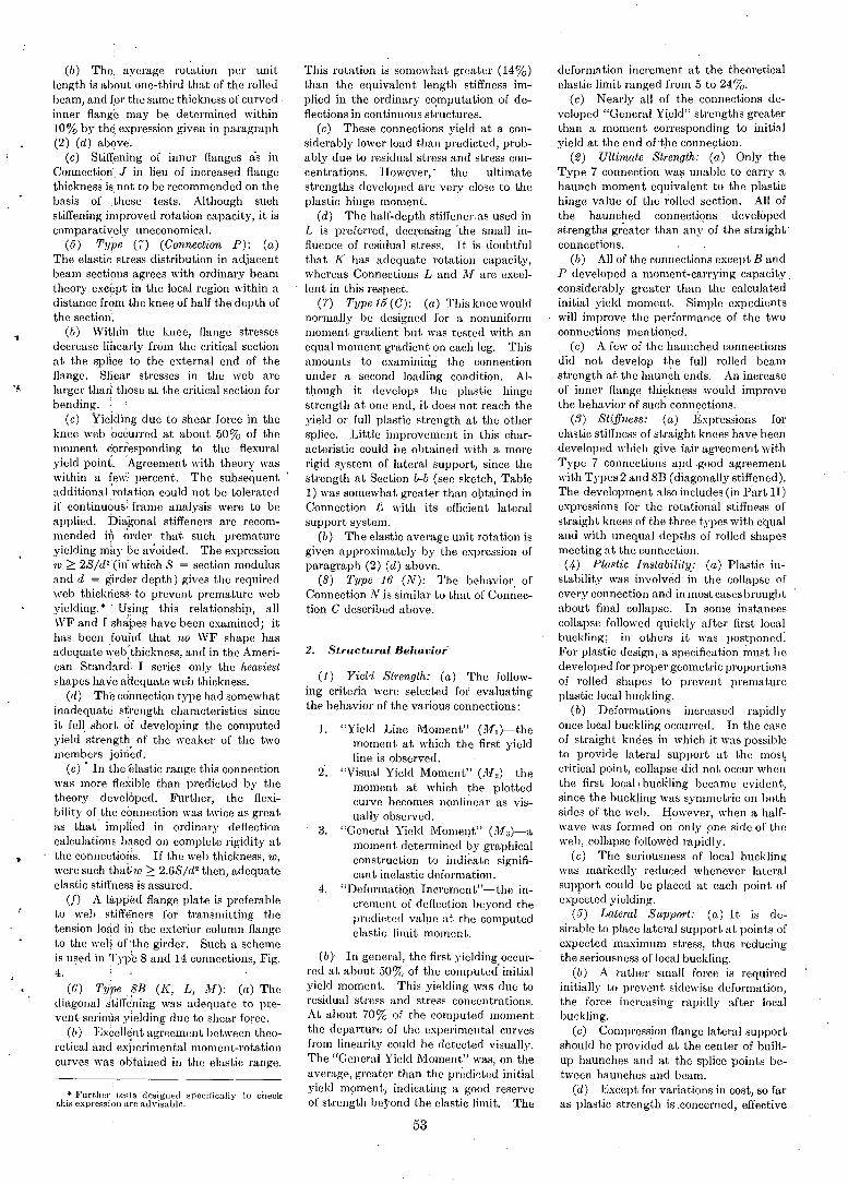
(b) The. average rotation per unitlength is abtJut one-third that of the rolledbeam, and fpr the same thickness of curved·inner flange I~lay be determined within10% by the expression given in paragraph(2) (d) abQve.
(c) Stiffening of inner flanges as inConnection J in lieu of increased flangethickness is. not to be recommended on thebasis of .these tests. Although suchstiffening improved rotation capacity, it iscomparatively uneconomical.
(5) Type (I) (Connection P): (a)The elastic stress distribution in adjacentbeam sections agrees with ordinary beamtheory except in the local region within adistance from the knee of half the depth ofthe section'.
(b) Within the knee, flange stressesdecrease linearly from the critical sectionat the splicc to the external end of theflange. Sliear stresses in the web arelarger than: those at the critical section forbending. :
(c) Yielding due to shear force in theknee web occurred at about 50% of themoment corresponding to the flexuralyield point. 'Agreement with theory waswithin a fe\\;.: percent. The subsequentadditional 'rotation could not be toleratedif continuous: frame analysis were to beapplied. Diagonal stiffeners are recommended in order that such prematureyielding mky be avoided. The expression10 2: 2S/d2 (in"which S = section modulusand d = girder depth) gives the requiredweb thickriess:· to prevent premature webyielding. * . Using this relationship, allWF and Ishdbes have been examined; ithas been fou'i1d that no WF shape hasadequate web 'thickness, and in the American Standard: I series only the heaviestshapes have aHequate web thickness.
(d) The coimection type had somewhatinadequate strength characteristics sinceit fell short of developing the computedyield strength of the weaker of the twomembers joiried.
(e) • In the elastic range this connectionwas more flexible than predicted by thetheory developed. Further, the flexibilityof the connection was twice as greatas that' impHed in ordinary deflectioncalculations based on complete rigidity atthe connections. If the web thickness, 10,
were such that:w 2: 2.6S/d2 then, adequateelastic stiffness is assured.
(f) A lli,PI)ed flange plate is preferableto web stiffc'ners for transmitting thetension load in the exterior column flangeto the weQ of "the girder. Such a schemeis used in Typ'e Sand 14 connections, Fig.4.
(6) Type 8E (K, L, M): (a) Thediagonal stiffe'ning was adequate to prevent serious yielding due to shear force.
(b) Excellent agreement between theoretical and exj)erimental moment-rotationcurves was ol:itained in the elastic range.
* Further tests designed specifically to checkthis expression arc ad visable.
This rotation is somewhat greater (14%)than the equivalent length stiffness implied in the ordinary co.mputation of deflections in continuous structures.
(c) These connections yield at a considerably lower load than predicted, probably due to residual stress and stress concentrations. However, " the ultimatestrengths developed are very close to theplastic hinge moment.
(d) The half-depth stiffener. as used inL is prefeITed, deCI;easing "the small influence of residual stress. It is doubtfulthat K has adequate rotation capacity,whereas Connections Land i}[ are excellent in this respect.
(7) Type 15(C): (a) Thiskneewouldnormally be designed for a nonuniformmoment gradient but was tested with anequal moment gradient on eaeb. leg. Thisamounts to examining the connectionunder a second loading eondition. Although it develops the plastie hingestrength at one end, it does not reach theyield or full plastic strength at the othersplice. Little improvement in this characteristic could be obtained with a morerigid system of lateral support, since thestrength at Section b-b (see sketch, Table1) was somewhat greater than obtained inConnection L with its efficient lateralsupport system.
(b) The elastic average unit rotation isgiven approximately by the expression ofparagraph (2) (d) above.
(8) Type 16 (N): The behavior ofConnection N is similar to that of Con~ection C described above.
2. Structrtral Behavior'
(1) Yield Strength: (a) The following criteria were selected for evaluatingthe behavior of the various connections:
1. "Yield Line Moment" (MI)-themoment at which the first yieldline is observed.
2. "Visual Yield Moment" (M2)-themoment at which the plottedcurve becomes nonliilCar as visually observed.
3. "General Yield Moment" (1113)-amoment determined by graphicalconstruction to indicate significant inelastic deform\ttion.
4. "Deformation Increment"-the increment of defleetion beyond thepredieted value at Lhe computedelastie limit moment.
(b)' In general, the first yielding' occur- .rcd at about 50% of the eomputed' initialyield moment. This yielding was due toresidual stress and stress coneentrations.At about 70% of the eomputed momentthe departure of the experimental curvesfrom linearity eould be detected visually.The "General Yield Moment" was, on theaverage, greater than the prcdieted initialyield moment, indieating a good reserveof strength bej'ond the elastic limit. The
53
deformation increment at the theoreticalclastic limit ranged from 5 to 24%.
(c) N early all of the connections developed "General Yield" strengths greaterthan a moment corresponding to initialyield at the end of "the connection.
(2) Ultimate Strength: (a) Only theType 7 connection was unable to carry ahaunch momcnt equivalent to the plastichinge value of the rolled section. All ofthe haunehed conneetipns developedstrengths gI~eater than any of the straight·connections.
(b) All of the connections except BandP developed a moment-carrying capacity.considerably greater than the calculatedinitial yield moment. Simple expedientswill improve the performance of the twoconnections mentioned.
(c) A few of the haunched connectionsdid not develop the full rolled beamstrength at the haunch ends. An increaseof inner flange thickness would improvethe behavior of such connections.
(3) Stiffness: (a) Expressions forelastic stiffness of straight knees have beendeveloped wllich give fair agreement withType 7 connections apd .good agreementwith T)1Jes 2 and SB (diagonally stiffened).The developmenL also includes (in Part II)expressions fOI" the rotatio1U11 stiffness ofstraight knees of the three types with equaland with unequal depths of rolled shapesmeeting at the eonnection.(4) Plastic Instability.: (a) Plastic in
stability was involved in the collapse ofevery connection and in most eases broughtabout final collapse. In some instancescollapse followed quickly after first localbuckling; in others it was postponed:For plastic design,. a specification must bedeveloped for proper geometric proportionsof rolled shapes to prevent prematureplastic local buckling.
(b) Deformations increased rapidlyonce local buckling occurred. In the caseof straight knees in which it was possibleto provide lateral support at the most,critical point, collapse did not occur whenthe first loeall buckling became evident,since the buckling was symmetric on bothsides of the web. However, when a halfwave was formed on only pne side of theweb, collapse followed rapidly.
(c) The seriousness of local bucklingwas markedly reduced whenever lateralsupport could be placed at each point ofexpected yielding.
(5) Lateral Support: (a) It is desirable to place lateral support at points ofexpected maximum stress, thus reducingthe seriousness of local buckling.
(b) A rather small force is requiredinitially to prevent sidewise deformation,the force increasing rapidly after localbuckling.
(c) Compression flange lateral supportshould be provided at the center of builtup haunches and at the spliee points between haunches and beam.
(d) Except for variations in eost, so faras plastic strength is .concerned, effective
w
SL
Mr
,I\
:o
r
(I
\
TERMINOLOGY
= observed yield line moment.= observed visual yield moment.= observed general yield moment.= observed maximum moment.= average lower yield point stress.= Young's modulus of elasticity.= shearing modulus of elasticity.
, = average unit rotation.. = rotation measured over equiva-~:
lent length of connection.= rotation in connection due to
shear.= rotation in connection due to
bending.
,.i
General yield moment: The moment atwhich the deformations due to this moment begin to affect the structural behavior elsewhere in a structure. Thevalue is determined g;'aphically as shown -'in Fig. 76.
Haunch depth: The mmlmumdistancefrom the external corner to the innerflange.
Haunch moment: The moment at the,haunch point.
Haunch point: The intersection of theextended neutral lines of girder andcolumn.
Initial yield moment: A'computed moment /,.at which the nominal maximum stressreaches the yield point, excluding theinfluence of stress concentrations andresidual stresses.
Liider's line: Wedge or plane of yieldingwhich forms in mild steel in the vicinityof the yield point.
Plastic hinge moment: The ultimate moment that can be reached at a sectionaccording to the simple plastic theory.
Rolled section moment: The moment at thejunction of the rolled beam and theknee. .
Rotation capacity: The ability of a struc- ;tural member to rotate under' nearconstant moment.
Visual yield moment: The moment at I
which the plotted curve becomes non- ~
linear, as observed visually (see Fig. (
76). "Yield line: Flaking of mill scale following
the formation of Liid~r's line as revealed by whitewash.
Yield line mOl/wnt: The momcnt at whichthe first yield line is observed (see Fig/'76). . ;
Yield strength: The load or moment at,which a significan~ amount of yieldingoccurs as indicated by available criteria.
(3
Mel)M(2)
MmlJ1'(4)<J'y
EG<P<PA
= area of section.= area of web.= equivalent stiffener area.= flange width.= total width of stiffener.= llepth of section.
"haunch depth," the minimumdistance from the externalcorner of the haunch to theinner flange.
= web thickness.= flange thickness.= stiffener thickness.= moment of inertia of section.= moment of inertia of the flanges
only.= section modulus of beam.= distance between the point of in
flection and the haunch pointin an actual frame.
ilL = .equivalent.length of a connection.lJ1'h "haunch" moment.Mh(T) = ".haunch" moment at which yield
occurs due to shear force.111'he,,) = "haunch" moment at \\'hich yield
occurs due to Hexure.= moment in a connection at junc
tion of rolled beam and connection.
lJ1'p = "hinge" value; full plastic moment; the ultimate momentthat can be reached accordingto the simple plastic theory.
"hinge" value at haunch.= initial yield moment.= moment at which yield point
t: ~ stress is reached at the end of.' ' .. the rolled section.
Ma
M(;)
lJ1' (y)
~
IV. HEFERENCES
NOMENCLATURE
(References 1-32 will be found in Part I of thepaper)
33. Johnston, Bruce G.. "The StructuralSignificance of Stress," Ci•. Eng., 9 (5), 291-294(1939).
34. Yang, C. H., Beedle, Lynn S., and Johnston, Bruce G., Progress Report No.5, "ResidualStress and t.he Yield Strength of Steel Beams,"THE WELDIN.G JOURNAL, 31 (4), Research SuppJ.205-s t.o 229-s (1952).
35. Beedle, Lynn. S., and Project Staff,Progress Report M, "General Summary Report," Fritz Enp;ineering Laboratory ReportNo. 205.13, Sept. 17, 1951.
Fritz Engineering Laboratory of whichProf. William J. Eney is Director. Acknowledgment is Jilso due Jan M. Ruzek,Research Assistant, for his tireless help inthe early part of the test program, toProf. C. D. Jensen who has contributedsuggestions in parts of the manuscript, andto Kenneth R. Harpel, foreman, and thestaff of machinists and technicians at theFritz Engineering Laboratory.
The authors wish to express their appreciation to the sponsors of this researchprogram. Ac~nowledgment is also expressed for the help and support receivedfrom members of the Lehigh Project Subcommittee (Welding Research Council),particularly that of its Chairman, T. R.Higgins. William Spraragen, Director,Welding Research Council, and LaMotteGrover, Chairman, Structural Steel Committee, have generously contributed theirsuggestions and criticisms.
This work has been carried out in ·the
III. ACKNOWLEDGMENTS
lateral support is more important than thevariations in fabrication details.
(6) Rotation Capacity (as influencingplastic design): (a) A straight connectionmust have "rotation capacity," the abilityto rotate through a considerable unit anglechange after the plastic hinge moment hasbeen reached if the frame is to be treatedin accordance with plastic design technique. Theamount depends on the proportions and loading of the frame. By way
.of illustration, a rotation capacity of abouteight times the rotation at initial yield isr'equired in the case of a third-point-loadcd
.beam attached t~ very stiff columns.With adequate lateral support theType8Bconnections are satisfactory in this respectwhile the behavior of Type 2 is not.
(b) Most of the built-up knees collapserapidly after first local buckling. However, rotation capacity usually is not required of haunched connections. Suchconnections are generally associated onlywith elastic design principles.
(c) When rotation capacity is desired,it could be obtained in some haunchedconnections by increasing the strength ofthe knee slightly beyond that requirede'lastically so that yield would occur'at thepoint where .the haunch and girder arejoined.
(d) Rotation capacity implies theability of the knee to deform withoutexhibiting marked local or lateral buckling.Thick flanges and effective lateral supportare most helpful in this respect.
(7) Cost of Fabrication: (a) Thereisan almost linear relation between the timerequired for cutting and welding and thetotal length of haunch as measured alongthe neutral lines. Connections Nand Jare exceptions.
(b) Sniped, half-depth stiffeners aresatisfactory and are less expensive thaneither the full-depth sniped stiffeners orthe complete stiffeners welded to the webarid to both top and bottom Hange.
1.,
541
'i'I