Embed Size (px)
Citation preview
EKT 221 : Digital 2EKT 221 : Digital 2MUX-based Transfer MUX-based Transfer
Multiplexer-Based Multiplexer-Based TransfersTransfers
A dedicated multiplexer is used to select the wanted input.
A simple technique using multiplexers for selection is introduced to allow multiple microoperations on a single register.
From previous lecture, we saw that multiplexers and parallel load registers can be used to implement dedicated transfers from multiple sources.
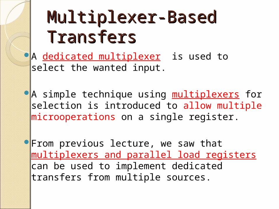
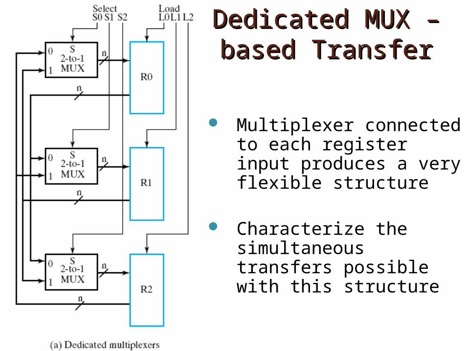
Dedicated Dedicated MUX – based MUX – based
TransferTransfer Three n-bit 2:1 MUX, each with its own SELECT signal
◦ MUX0 : S0◦ MUX1 : S1◦ MUX2 : S2
Each register has its own LOAD signal
◦ R0 : L0◦ R1 : L1◦ R2 : L2
MUX0
MUX1
MUX2
S0S1S2SELECT
L0L1L2 LOAD
Dedicated MUX – Dedicated MUX – based Transferbased Transfer
Multiplexer connected to each register input produces a very flexible structure
Characterize the simultaneous transfers possible with this structure
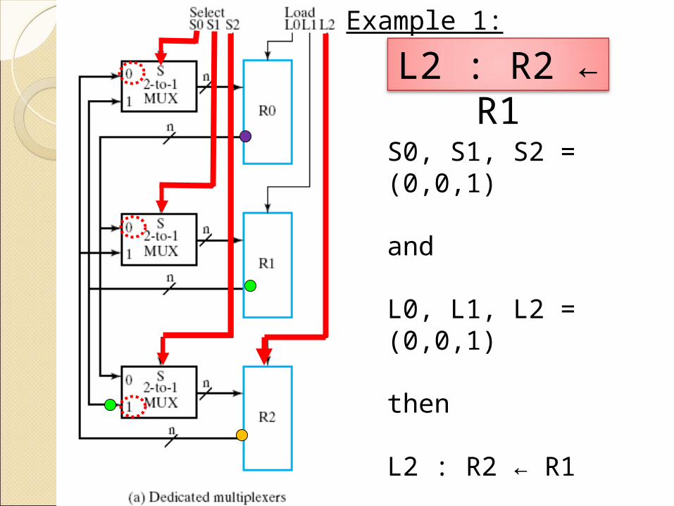
S0, S1, S2 = (0,0,1)
and
L0, L1, L2 = (0,0,1)
then
L2 : R2 ← R1
L2 : R2 ← R1
Example 1:
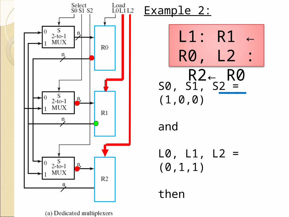
S0, S1, S2 = (1,0,0)
and
L0, L1, L2 = (0,1,1)
then
L1: R1 ← R0, L2 : R2← R0
Example 2:
L1: R1 ← R0, L2 : R2← R0
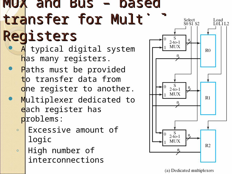
MUX and Bus – based transfer MUX and Bus – based transfer for Multiple Registersfor Multiple Registers
A typical digital system has many registers.
Paths must be provided to transfer data from one register to another.
Multiplexer dedicated to each register has problems:
◦ Excessive amount of logic◦ High number of
interconnections
MUX and Bus – based transfer MUX and Bus – based transfer for Multiple Registersfor Multiple Registers
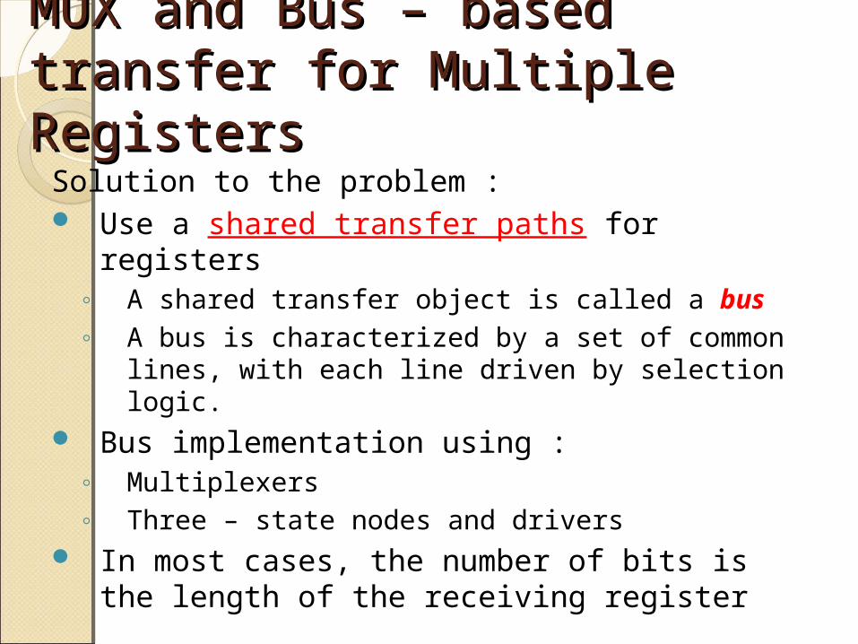
Solution to the problem : Use a shared transfer paths for registers
◦ A shared transfer object is called a bus◦ A bus is characterized by a set of common
lines, with each line driven by selection logic.
Bus implementation using :◦ Multiplexers◦ Three – state nodes and drivers
In most cases, the number of bits is the length of the receiving register
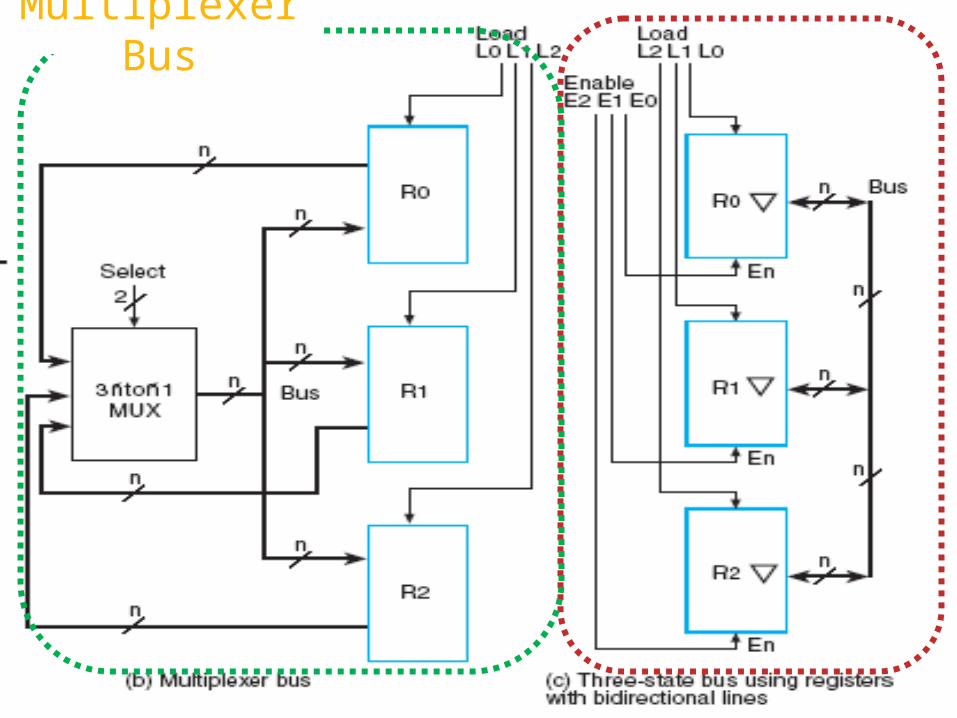
Multiplexer BusMultiplexer Bus
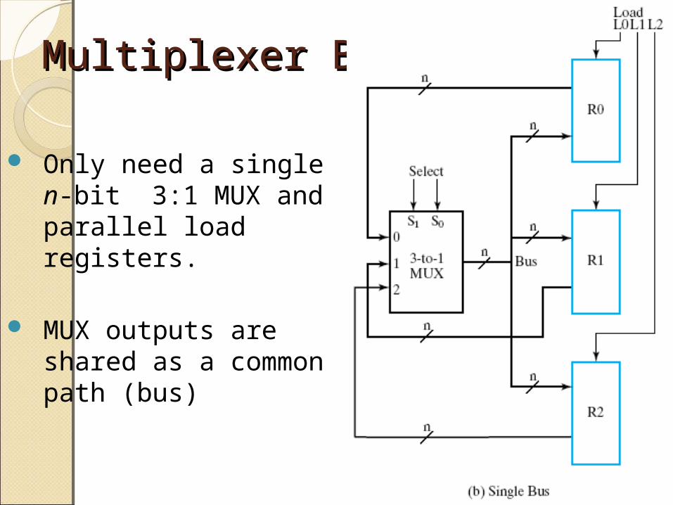
Only need a single n-bit 3:1 MUX and parallel load registers.
MUX outputs are shared as a common path (bus)
Multiplexer BusMultiplexer Bus
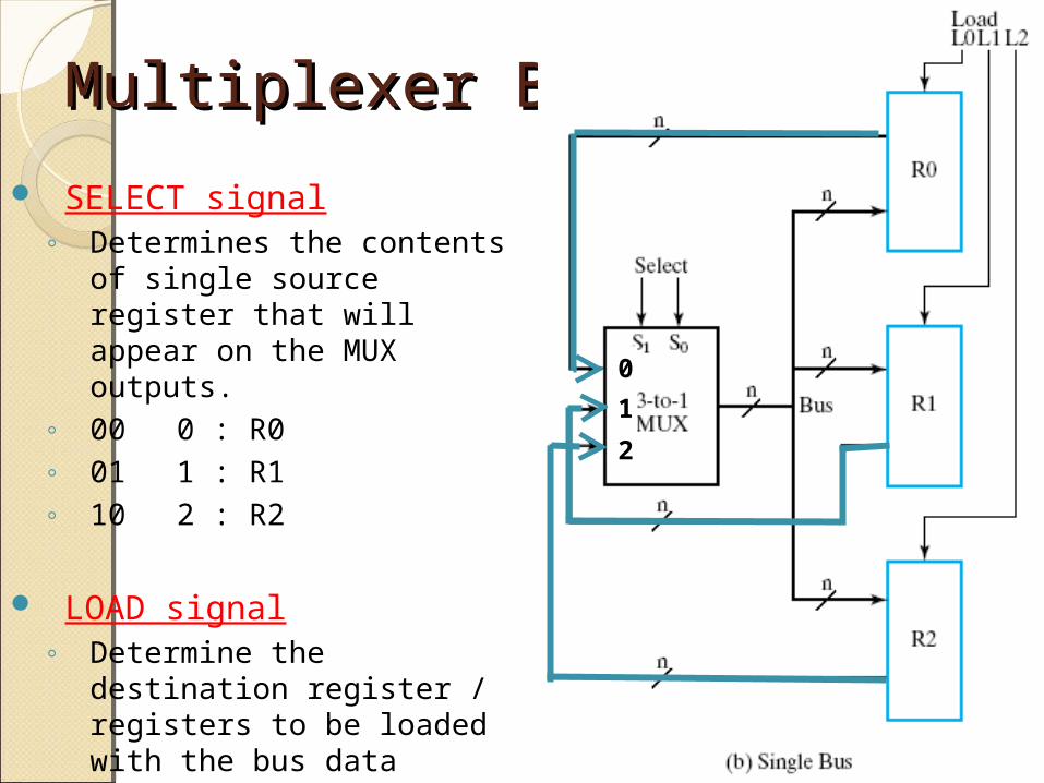
SELECT signal◦ Determines the contents
of single source register that will appear on the MUX outputs.
◦ 00 0 : R0◦ 01 1 : R1◦ 10 2 : R2
LOAD signal◦ Determine the destination
register / registers to be loaded with the bus data
0
1
2
Multiplexer BusMultiplexer Bus
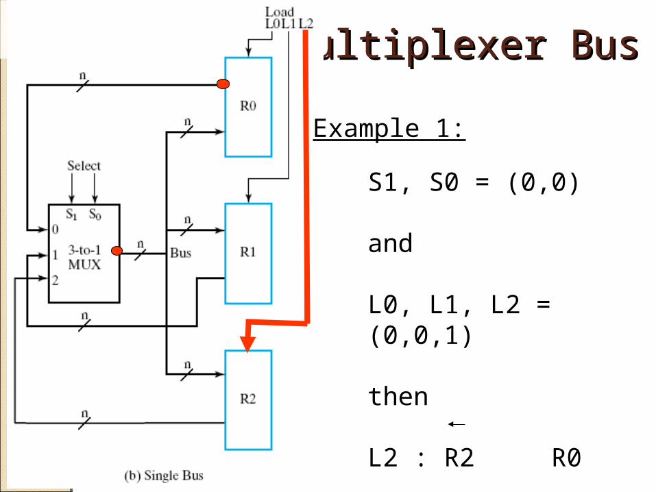
S1, S0 = (0,0)
and
L0, L1, L2 = (0,0,1)
then
L2 : R2 R0
Example 1:
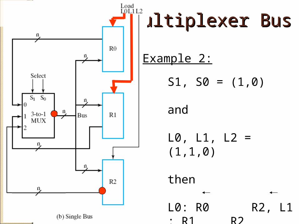
Multiplexer BusMultiplexer Bus
Example 2:
S1, S0 = (1,0)
and
L0, L1, L2 = (1,1,0)
then
L0: R0 R2, L1 : R1 R2
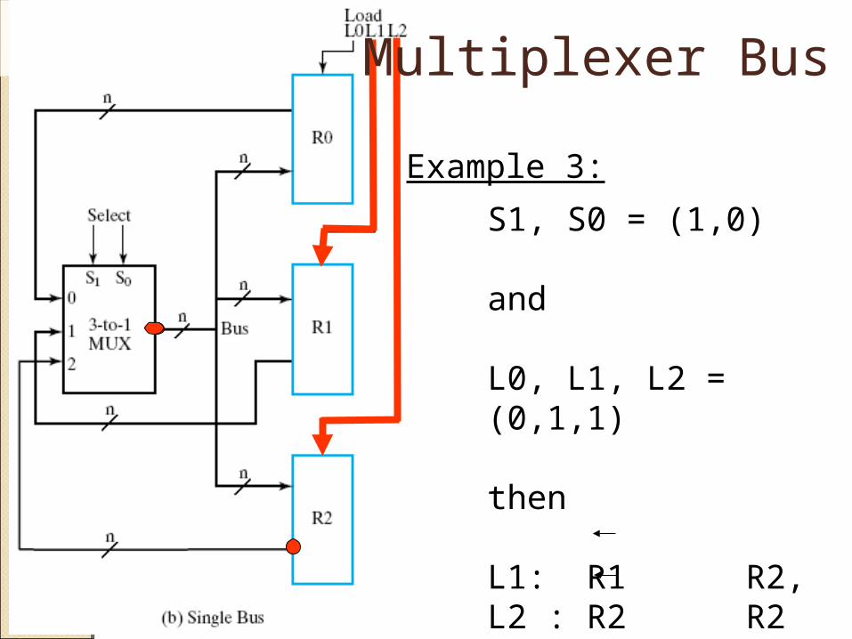
Example 3:
S1, S0 = (1,0)
and
L0, L1, L2 = (0,1,1)
then
L1: R1 R2, L2 : R2 R2 (no change)
Multiplexer Bus
Multiplexer BusMultiplexer Bus
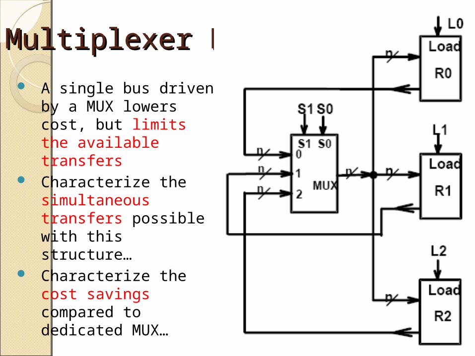
A single bus driven by a MUX lowers cost, but limits the available transfers
Characterize the simultaneous transfers possible with this structure…
Characterize the cost savings compared to dedicated MUX…
Multiplexer BusMultiplexer Bus
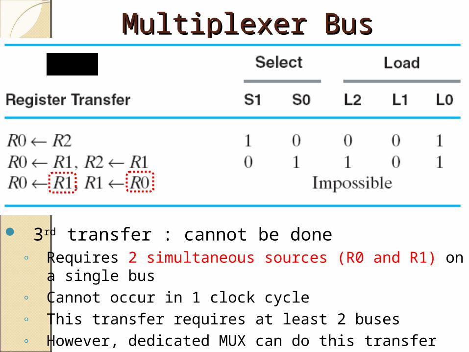
3rd transfer : cannot be done◦ Requires 2 simultaneous sources (R0 and R1) on a
single bus◦ Cannot occur in 1 clock cycle◦ This transfer requires at least 2 buses◦ However, dedicated MUX can do this transfer
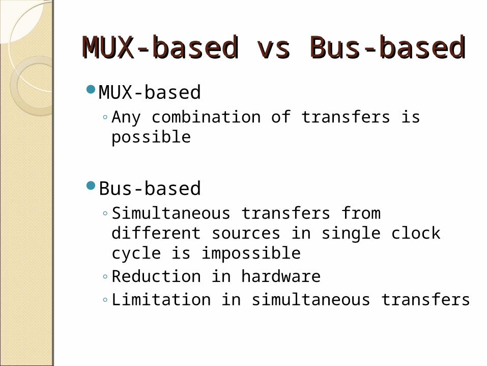
MUX-based vs Bus-basedMUX-based vs Bus-basedMUX-based
◦Any combination of transfers is possible
Bus-based◦Simultaneous transfers from
different sources in single clock cycle is impossible
◦Reduction in hardware◦Limitation in simultaneous transfers
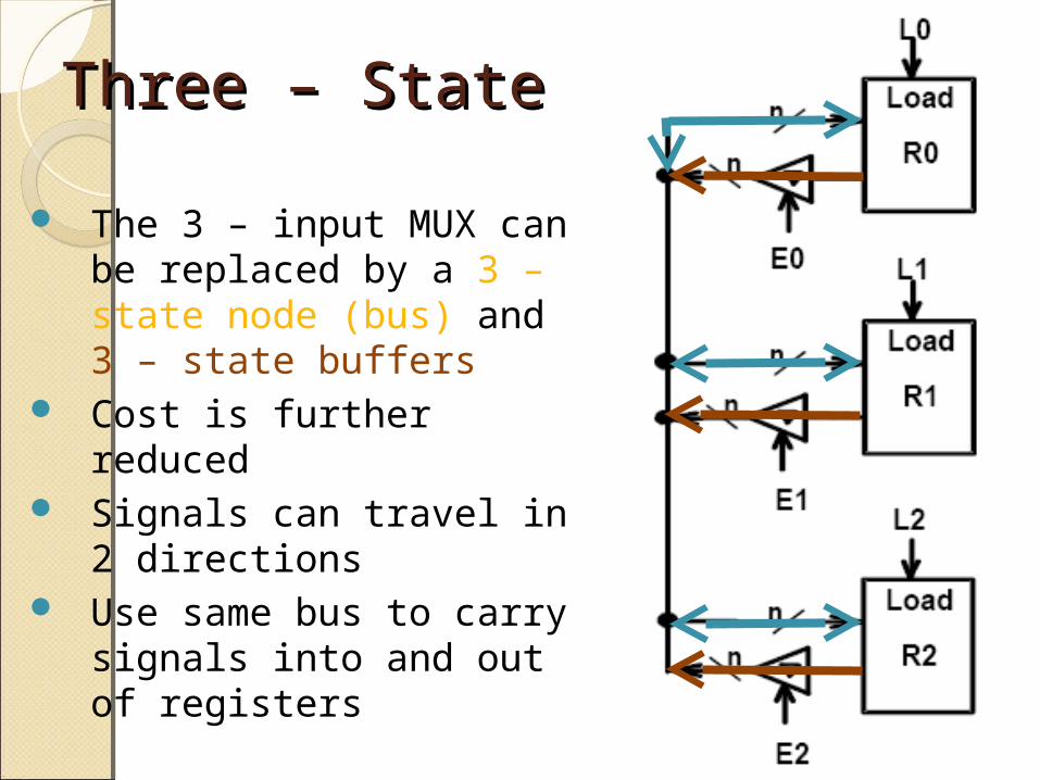
Three – State BusThree – State Bus
The 3 – input MUX can be replaced by a 3 – state node (bus) and 3 – state buffers
Cost is further reduced Signals can travel in 2
directions Use same bus to carry
signals into and out of registers
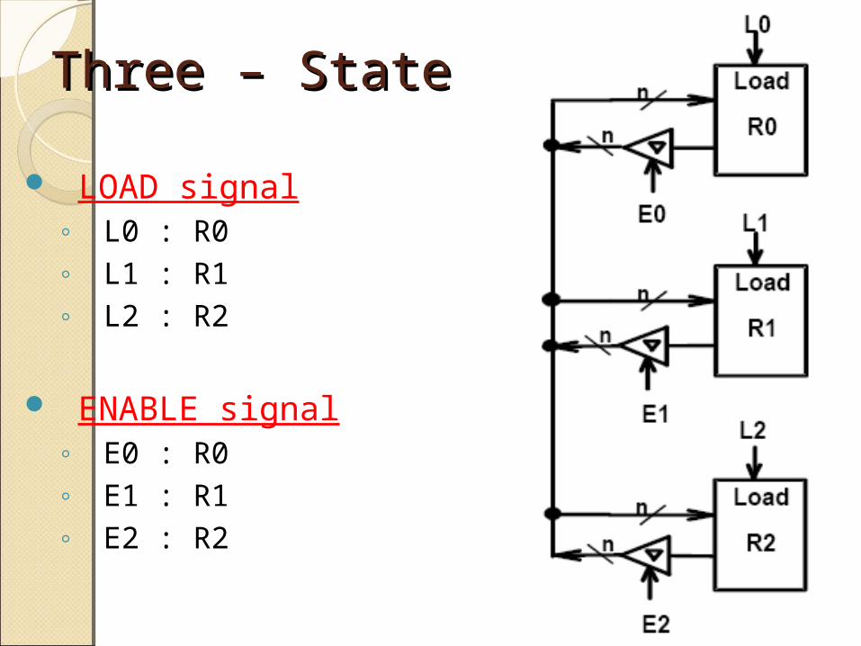
Three – State BusThree – State Bus
LOAD signal◦ L0 : R0◦ L1 : R1◦ L2 : R2
ENABLE signal◦ E0 : R0◦ E1 : R1◦ E2 : R2
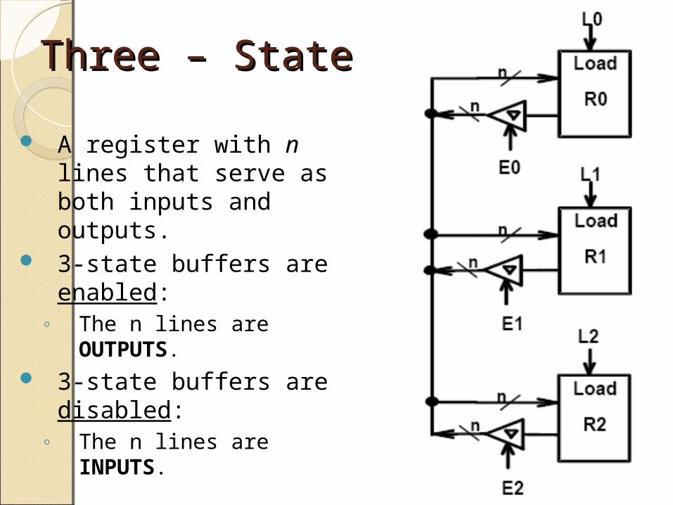
Three – State BusThree – State Bus
A register with n lines that serve as both inputs and outputs.
3-state buffers are enabled:
◦ The n lines are OUTPUTS.
3-state buffers are disabled:
◦ The n lines are INPUTS.
Three Three – –
StateStateBusBus
Multiplexer Bus

Thank YouThank You