Embed Size (px)
Citation preview

04.07 -
11.14
51040407
EJE 110 / 116 / 118 / 120
Operating instructions G
EJE 116
EJE 118
EJE 120
EJE 110

G

11.1
4 E
N
4
11.1
4 E
N
4

5
11.1
4 E
N
Foreword
Notes on the operating instructions
The present ORIGINAL OPERATING INSTRUCTIONS are designed to providesufficient instruction for the safe operation of the industrial truck. The information isprovided clearly and concisely. The chapters are arranged by letter and the pages arenumbered continuously.
The operator manual details different industrial truck models. When operating andservicing the industrial truck, make sure that the particular section applies to yourtruck model.
Our trucks are subject to ongoing development. Jungheinrich reserves the right toalter the design, equipment and technical features of the system. No guarantee ofparticular features of the truck should therefore be assumed from the presentoperating instructions.
Safety notices and text mark-ups
Safety instructions and important explanations are indicated by the followinggraphics:
DANGER!
Indicates an extremely hazardous situation. Failure to comply with this instruction willresult in severe irreparable injury and even death.
WARNING!
Indicates an extremely hazardous situation. Failure to comply with this instructionmay result in severe irreparable injury and even death.
CAUTION!
Indicates a hazardous situation. Failure to comply with this instruction may result inslight to medium injury.
NOTE
Indicates a material hazard. Failure to comply with this instruction may result inmaterial damage.
Z Used before notices and explanations.
Copyright
Copyright of these operating instructions remains with JUNGHEINRICH AG.
t Indicates standard equipmento Indicates optional equipment

11.1
4 E
N
6
Jungheinrich Aktiengesellschaft
Am Stadtrand 3522047 Hamburg - Germany
Tel: +49 (0) 40/6948-0
www.jungheinrich.com
11.1
4 E
N
6
Jungheinrich Aktiengesellschaft
Am Stadtrand 3522047 Hamburg - Germany
Tel: +49 (0) 40/6948-0
www.jungheinrich.com

7
11.1
4 E
N
Table of Contents
A Correct Use and Application ................................................... 9
1 General.................................................................................................... 92 Correct application................................................................................... 93 Approved application conditions.............................................................. 94 Proprietor responsibilities ........................................................................ 105 Adding attachments and/or accessories.................................................. 10
B Truck Description .................................................................... 11
1 Application ............................................................................................... 111.1 Truck models and rated capacity............................................................. 112 Assemblies and Functional Description................................................... 122.1 Assembly Overview ................................................................................. 122.2 Functional Description ............................................................................. 133 Technical Specifications .......................................................................... 143.1 Performance data .................................................................................... 143.2 Dimensions.............................................................................................. 153.3 Weights.................................................................................................... 173.4 Tyre type.................................................................................................. 173.5 EN norms................................................................................................. 183.6 Conditions of use..................................................................................... 193.7 Electrical requirements ............................................................................ 194 Identification points and data plates ........................................................ 204.1 Data plate ................................................................................................ 21
C Transport and Commissioning ................................................ 23
1 Lifting by crane ........................................................................................ 232 Transport ................................................................................................. 243 Using the Truck for the First Time ........................................................... 25
D Battery - Servicing, Recharging, Replacement ....................... 27
1 Safety Regulations Governing the Handling of Lead-Acid Batteries ....... 272 Battery types............................................................................................ 293 Exposing the battery................................................................................ 304 Charging the battery ................................................................................ 314.1 Charging the battery with a stationary charger........................................ 324.2 Charging the battery with an on-board charger ....................................... 335 Battery removal and installation .............................................................. 385.1 Changing the battery from the top ........................................................... 395.2 Lateral battery removal............................................................................ 40

11.1
4 E
N
8
E Operation ................................................................................ 41
1 Safety Regulations for the Operation of the Forklift Truck....................... 412 Displays and Controls.............................................................................. 422.1 Battery discharge indicator ...................................................................... 453 Starting up the truck ................................................................................ 463.1 Checks and operations to be performed before starting daily operation . 463.2 Preparing the truck for operation ............................................................. 473.3 Parking the truck securely ....................................................................... 483.4 Battery discharge monitor........................................................................ 484 Industrial Truck Operation ....................................................................... 494.1 Safety regulations for truck operation...................................................... 494.2 Emergency Disconnect, Travel, Steering, Braking .................................. 514.3 Lifting, transporting and depositing loads ................................................ 565 Troubleshooting....................................................................................... 595.1 Truck does not start ................................................................................. 595.2 Load cannot be lifted ............................................................................... 596 Operating the truck without its own drive system .................................... 607 Optional equipment ................................................................................. 617.1 Emergency operation with service key GF60 .......................................... 617.2 CanCode keypad..................................................................................... 637.3 Setting the truck parameters with CanCode............................................ 687.4 Parameters .............................................................................................. 707.5 CANDIS display instrument ..................................................................... 727.6 ISM access module (o)........................................................................... 73
F Industrial Truck Maintenance .................................................. 75
1 Operational Safety and Environmental Protection................................... 752 Maintenance Safety Regulations............................................................. 753 Servicing and Inspection ......................................................................... 794 Maintenance checklist ............................................................................. 804.1 Owner ...................................................................................................... 804.2 Customer Service .................................................................................... 815 Lubricants and Lubrication Schedule ...................................................... 845.1 Handling consumables safely.................................................................. 845.2 Lubrication Schedule ............................................................................... 865.3 Consumables........................................................................................... 876 Maintenance and repairs ......................................................................... 886.1 Preparing the truck for maintenance and repairs .................................... 886.2 Removing the front panel ........................................................................ 886.3 Removing the drive panel........................................................................ 896.4 Checking electrical fuses......................................................................... 906.5 Restoring the truck to service after maintenance and repairs ................. 917 Decommissioning the industrial truck ...................................................... 927.1 Prior to decommissioning ........................................................................ 937.2 Action to be taken during decommissioning ............................................ 937.3 Restoring the truck to service after decommissioning ............................. 948 Safety tests to be performed at intervals and after unusual incidents ..... 959 Final de-commissioning, disposal............................................................ 95

1
0506
.GB
Appendix
JH Traction Battery Operating Instructions
Z These operating instructions apply only to Jungheinrich battery models. If usinganother brand, refer to the manufacturer's operating instructions.
1
0506
.GB
Appendix
JH Traction Battery Operating Instructions
Z These operating instructions apply only to Jungheinrich battery models. If usinganother brand, refer to the manufacturer's operating instructions.

0506
.GB
2
0506
.GB
2

9
11.1
4 E
N
A Correct Use and Application
1 General
The industrial truck described in the present operating instructions is designed forlifting, lowering and transporting load units.It must be used, operated and serviced in accordance with the present instructions.Any other type of use is beyond the scope of application and can result in damage topersonnel, the industrial truck or property.
2 Correct application
NOTE
The maximum load and load distance are indicated on the load chart and must not beexceeded.The load must rest on the load handler or be lifted by an attachment approved by themanufacturer.The load must rest on the back of the fork carriage and centrally between the forks.
– Lifting and lowering of loads.– Transporting lowered loads.– Do not travel with a raised load (>500 mm).– Do not carry or lift passengers.– Do push or pull load units.
3 Approved application conditions
– Operation in industrial and commercial environments.– Permissible temperature range 5°C to 40°C.– Operation only on secure, level surfaces with sufficient capacity.– Operation only on routes that are visible and approved by the proprietor.– Negotiating inclines up to a maximum of 15 %.– Do not negotiate inclines crosswise or at an angle. Transporting loads downhill.– Operation in partially public traffic.
Z Special equipment and authorisation are required if the truck is to be used inextreme conditions.The truck is not authorised for use in areas at risk of explosion.

11.1
4 E
N
10
4 Proprietor responsibilities
For the purposes of the present operating instructions the “proprietor” is defined asany natural or legal person who either uses the industrial truck himself, or on whosebehalf it is used. In special cases (e.g. leasing or renting) the proprietor is consideredthe person who, in accordance with existing contractual agreements between theowner and user of the industrial truck, is charged with operational duties.The proprietor must ensure that the industrial truck is used only for the purpose forwhich it is intended and that there is no danger to life and limb of the user and thirdparties. Furthermore, accident prevention regulations, safety regulations andoperating, servicing and repair guidelines must be followed. The proprietor mustensure that all users have read and understood these operating instructions.
NOTE
Failure to comply with the operating instructions shall invalidate the warranty. Thesame applies if improper work is carried out on the truck by the customer or thirdparties without the permission of the manufacturer.
5 Adding attachments and/or accessories
Adding accessories
The mounting or installation of additional equipment which affects or enhances theperformance of the forklift truck requires the written permission of the manufacturer.Local authority approval may also need to be obtained.Local authority approval does not however constitute the manufacturer’s approval.

11
11.1
4 E
N
B Truck Description
1 Application
The EJE 110 / 116 / 118 / 120 is designed to transport goods on level surfaces. It canlift open bottom or diagonal board pallets as well as roll cages beyond the area of theload wheels. The capacity is shown on the capacity plate, Qmax.
1.1 Truck models and rated capacity
The rated capacity depends on the model. The rated capacity can be derived fromthe model description.
The rated capacity does not generally match the permissible capacity. The capacitycan be found on the load chart attached to the rack.
EJE110
EJE Model name1 Series
10 Rated capacity x 100 kg

11.1
4 E
N
12
2 Assemblies and Functional Description
2.1 Assembly Overview
Item
Description Item
Description
1 t Safety collision switch 8 o On-board charger24 V / 30 A(including safety switch)
2 t Travel switch 9 t Discharge indicator
o Display instrument (CANDIS)
3 t Slow travel button 10 t Key switch
o CANCODE keypad
o Key switch (also with second stage for brake release)
4 t Tiller 11 t Front panel
5 t Battery cover 12 t Two-section drive panel
6 t Emergency Disconnect 13 t Castor wheels
7 t Fork tines 14 t Drive wheel
t = Standard equipment o = Optional equipment
2
56 7
1
3
4
8
9
10
11
12
13 14 13

13
11.1
4 E
N2.2 Functional Description
Safety Mechanisms
– An enclosed, smooth truck geometry with rounded edges ensures safe handling ofthe truck.
– The wheels are surrounded by a solid skirt. – Pressing the Emergency Disconnect switch rapidly cuts out all electrical functions
in hazardous situations.
Emergency Stop safety feature
– The emergency stop is activated by the traction controller. – Each time the truck is switched on the system performed an automatic diagnosis.
Operator Position
– All travel and lift operations can be performed sensitively without having to reach.
Hydraulic system
– When lifting is activated, the pump unit starts to operate, supplying hydraulic oilfrom the oil reservoir to the lift cylinder.
– When the lift button is pressed the wheel arms are raised at an even speed; whenthe lower button is pressed the wheel arms are lowered.
Drive system
– A fixed AC threephase motor actuates the drive wheel via a bevel spur gearbox.– The electronic traction controller ensures smooth drive motor speed control and
hence smooth travel, powerful acceleration and electrically controlled braking withenergy regeneration.
– The driver can choose from 3 travel programs, depending on the load and theenvironment. from maximum performance to energy saving.
Steering
– The driver steers with an ergonomic control handle.– The drive system can be pivoted +/- 90°.
Electrical system
– 24 volt system. – Electronic traction control is standard.
Controls and Displays
– Ergonomic controls ensure fatigue-free operation for sensitive application of thetravel operations.
– The battery discharge indicator shows the available battery capacity.– The optional CanDis displays show the key driver information and travel program,
service hours, battery capacity and event messages.
13
11.1
4 E
N
2.2 Functional Description
Safety Mechanisms
– An enclosed, smooth truck geometry with rounded edges ensures safe handling ofthe truck.
– The wheels are surrounded by a solid skirt. – Pressing the Emergency Disconnect switch rapidly cuts out all electrical functions
in hazardous situations.
Emergency Stop safety feature
– The emergency stop is activated by the traction controller. – Each time the truck is switched on the system performed an automatic diagnosis.
Operator Position
– All travel and lift operations can be performed sensitively without having to reach.
Hydraulic system
– When lifting is activated, the pump unit starts to operate, supplying hydraulic oilfrom the oil reservoir to the lift cylinder.
– When the lift button is pressed the wheel arms are raised at an even speed; whenthe lower button is pressed the wheel arms are lowered.
Drive system
– A fixed AC threephase motor actuates the drive wheel via a bevel spur gearbox.– The electronic traction controller ensures smooth drive motor speed control and
hence smooth travel, powerful acceleration and electrically controlled braking withenergy regeneration.
– The driver can choose from 3 travel programs, depending on the load and theenvironment. from maximum performance to energy saving.
Steering
– The driver steers with an ergonomic control handle.– The drive system can be pivoted +/- 90°.
Electrical system
– 24 volt system. – Electronic traction control is standard.
Controls and Displays
– Ergonomic controls ensure fatigue-free operation for sensitive application of thetravel operations.
– The battery discharge indicator shows the available battery capacity.– The optional CanDis displays show the key driver information and travel program,
service hours, battery capacity and event messages.

11.1
4 E
N
14
3 Technical Specifications
Z Technical data specified in accordance with VDI 2198.Technical modifications and additions reserved.
3.1 Performance data
*) For longer fork lengths the load centre of gravity is in the centre of the forks
Description EJE 110 EJE 116 EJE 118 EJE 120
Q Rated capacity 1000 1600 1800 2000 kg
C Load centre distance for standard fork length *)
600 600 600 600 mm
Travel speedwith / without rated load
5,0 / 5,0 6,0 / 6,0 6,0 / 6,0 6,0 / 6,0 km/h
Lift speedwith / without rated load
0,04/0,05 0,04/0,05 0,04/0,05 0,04/0,05 m/s
Lowering speedwith / without rated load
0,05/0,04 0,05/0,04 0,05/0,04 0,05/0,04 m/s
Max. gradeability (5 min rating)with / without rated load
10 / 20 10 / 20 9 / 20 8 / 20 %
15
11.1
4 E
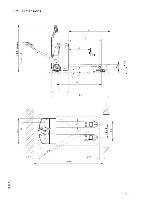
N3.2 Dimensions
15
11.1
4 E
N
3.2 Dimensions

11.1
4 E
N
16
* Load section raised / lowered +53 mm
** Diagonal in accordance with VDI +204 mm
Description EJE 110 / 116 / 118 / 120
Short version
h3 Lift 122 mm
h13 Load handler lowered 85 mm
h14 Tiller height in min./max. travel position 797 / 1313 mm
Y* Wheel base (short / long) 1255 / 1326 mm
l1 Overall length (short / long) 1644 / 1715 mm
l2 Length including fork shank (short, long) 494 / 565 mm
l Standard fork length 1150 mm
b1 Truck width 720 mm
b5 Outside straddle 540 mm
b10 Track width, front 508 mm
b11 Track width, rear 368 mm
e Fork width 172 mm
s Fork thickness 55 mm
m2 Ground clearance centre wheelbase 30 mm
x Load distance 911 mm
Wa* Turning radius 1440 / 1511 mm
Ast* Aisle width, pallet 800x1200 longitudinal (short/long) 1929**/2000** mm
Ast* Aisle width, pallet 1000x1200 longitudinal (short/long) 1879 / 1950 mm
a Safety distance 200 mm

17
11.1
4 E
N3.3 Weights
3.4 Tyre type
Description EJE 110 EJE 116 EJE 118 EJE 120
Net weight; s / m 439 / 508 439 / 508 441 / 510 445 / 514 kg
Axle load with loadfront / rear
737 / 1302 737 / 1302 787 / 1454 836 / 1609 kg
Axle load without loadfront / rear
346 / 93 346 / 93 347 / 94 351 / 94 kg
Description EJE 110 EJE 116 EJE 118 EJE 120
Tyre size, front 230 x 65 230 x 70 230 x 70 230 x 70 mm
Tyre size, rear; single / tandem
ø85x110 / ø85x85
ø85x110 / ø85x85
ø85x110 / ø85x85
mm
Additional wheels (dimensions)
ø100x40 ø100x40 ø100x40 ø100x40 mm
Wheels, number front / rear (x = driven)
1x +2 /2 or 4
17
11.1
4 E
N
3.3 Weights
3.4 Tyre type
Description EJE 110 EJE 116 EJE 118 EJE 120
Net weight; s / m 439 / 508 439 / 508 441 / 510 445 / 514 kg
Axle load with loadfront / rear
737 / 1302 737 / 1302 787 / 1454 836 / 1609 kg
Axle load without loadfront / rear
346 / 93 346 / 93 347 / 94 351 / 94 kg
Description EJE 110 EJE 116 EJE 118 EJE 120
Tyre size, front 230 x 65 230 x 70 230 x 70 230 x 70 mm
Tyre size, rear; single / tandem
ø85x110 / ø85x85
ø85x110 / ø85x85
ø85x110 / ø85x85
mm
Additional wheels (dimensions)
ø100x40 ø100x40 ø100x40 ø100x40 mm
Wheels, number front / rear (x = driven)
1x +2 /2 or 4

11.1
4 E
N
18
3.5 EN norms
Noise emission level
– EJE 110 / 116 / 118 / 120: 70 dB(A)
in accordance with EN 12053 as harmonised with ISO 4871.
Z The noise emission level is calculated in accordance with standard procedures andtakes into account the noise level when travelling, lifting and when idle. The noiselevel is measured at the level of the driver's ear.
Electromagnetic compatibility (EMC)
The manufacturer confirms that the truck adheres to the limits for electromagneticemissions and resistance as well as the static electricity discharge test in accordancewith EN 12895 as well as the standardised instructions contained therein.
Z No changes to electric or electronic components or their arrangement may bemade without the written agreement of the manufacturer.
WARNING!
Medical equipment can be damaged by non-ionised radiationElectrical equipment on the truck emitting non-ionised radiation (e.g. wireless datatransmission) can affect operators' medical equipment (pacemakers, hearing aidsetc.) and result in malfunctions. Consult with a doctor or the medical equipmentmanufacturer to clarify whether it can be used near the industrial truck.
19
11.1
4 E
N3.6 Conditions of use
Ambient temperature
– operating at 5°C to 40°C
Z Special equipment and authorisation are required if the truck is to be constantlyused in conditions of extreme temperature or air humidity fluctuations.
3.7 Electrical requirements
The manufacturer certifies compliance with the requirements for the design andmanufacture of electrical equipment, according to EN 1175 "Industrial Truck Safety -Electrical Requirements", provided the truck is used according to its purpose.
19
11.1
4 E
N
3.6 Conditions of use
Ambient temperature
– operating at 5°C to 40°C
Z Special equipment and authorisation are required if the truck is to be constantlyused in conditions of extreme temperature or air humidity fluctuations.
3.7 Electrical requirements
The manufacturer certifies compliance with the requirements for the design andmanufacture of electrical equipment, according to EN 1175 "Industrial Truck Safety -Electrical Requirements", provided the truck is used according to its purpose.

11.1
4 E
N
20
4 Identification points and data plates
Item Description15 Truck data plate16 Capacity Qmax17 Decal: “No passengers”18 Strap point for crane lifting19 Test plaque (o)20 Model description
Qmax XXX kg
15
19
1617
18
20
11.1
4 E
N
20
4 Identification points and data plates
Item Description15 Truck data plate16 Capacity Qmax17 Decal: “No passengers”18 Strap point for crane lifting19 Test plaque (o)20 Model description
Qmax XXX kg
15
19
1617
18
20

21
11.1
4 E
N4.1 Data plate
Z For queries regarding the truck or ordering spare parts always quote the truck serialnumber (22).
21 22 2423 25
32
28
31
30
29
2726
Item Description Item Description21 Type 27 Year of manufacture22 Serial number 28 Load centre (mm)23 Rated capacity (kg) 29 Output24 Battery voltage (V) 30 Min./max. battery weight (kg)25 Net weight w.o. battery (kg) 31 Manufacturer26 Option 32 Manufacturer’s logo
21
11.1
4 E
N
4.1 Data plate
Z For queries regarding the truck or ordering spare parts always quote the truck serialnumber (22).
21 22 2423 25
32
28
31
30
29
2726
Item Description Item Description21 Type 27 Year of manufacture22 Serial number 28 Load centre (mm)23 Rated capacity (kg) 29 Output24 Battery voltage (V) 30 Min./max. battery weight (kg)25 Net weight w.o. battery (kg) 31 Manufacturer26 Option 32 Manufacturer’s logo

11.1
4 E
N
22
11.1
4 E
N
22
23
11.1
4 E
N
C Transport and Commissioning
1 Lifting by crane
WARNING!
Improper lifting by crane can result in accidentsThe use of unsuitable lifting gear can cause the truck to crash when being lifted bycrane.Prevent the truck from striking other objects when it is being raised, and avoid anyinvoluntary movements. If necessary secure the truck with guide ropes.The truck should only be handled by people who are trained in using lifting slings
and tools.Wear safety shoes when lifting the truck by crane.Do not stand under a swaying load.Do not walk into or stand in a hazardous area.Always use lifting gear with sufficient capacity (for truck weight see truck data
plate).Always attach the crane slings to the prescribed strap points and prevent them from
slipping.Use the lifting gear only in the prescribed load direction.Crane slings should be fastened in such a way that they do not come into contact
with any attachments when lifting.
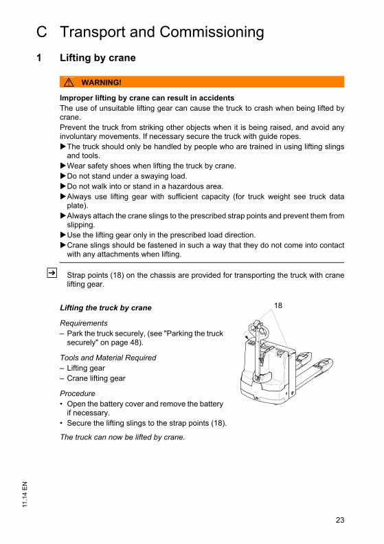
Z Strap points (18) on the chassis are provided for transporting the truck with cranelifting gear.
Lifting the truck by crane
Requirements– Park the truck securely, (see "Parking the truck
securely" on page 48).
Tools and Material Required– Lifting gear– Crane lifting gear
Procedure• Open the battery cover and remove the battery
if necessary.• Secure the lifting slings to the strap points (18).
The truck can now be lifted by crane.
18
23
11.1
4 E
N
C Transport and Commissioning
1 Lifting by crane
WARNING!
Improper lifting by crane can result in accidentsThe use of unsuitable lifting gear can cause the truck to crash when being lifted bycrane.Prevent the truck from striking other objects when it is being raised, and avoid anyinvoluntary movements. If necessary secure the truck with guide ropes.The truck should only be handled by people who are trained in using lifting slings
and tools.Wear safety shoes when lifting the truck by crane.Do not stand under a swaying load.Do not walk into or stand in a hazardous area.Always use lifting gear with sufficient capacity (for truck weight see truck data
plate).Always attach the crane slings to the prescribed strap points and prevent them from
slipping.Use the lifting gear only in the prescribed load direction.Crane slings should be fastened in such a way that they do not come into contact
with any attachments when lifting.
Z Strap points (18) on the chassis are provided for transporting the truck with cranelifting gear.
Lifting the truck by crane
Requirements– Park the truck securely, (see "Parking the truck
securely" on page 48).
Tools and Material Required– Lifting gear– Crane lifting gear
Procedure• Open the battery cover and remove the battery
if necessary.• Secure the lifting slings to the strap points (18).
The truck can now be lifted by crane.
18

11.1
4 E
N
24
2 Transport
WARNING!
Accidental movement during transportImproper fastening of the truck and mast during transport can result in seriousaccidents.Loading must be carried out by specially trained staff in accordance with
recommendations contained in Guidelines VDI 2700 and VDI 2703 In each casecorrect measurements must be made and appropriate safety measures adopted.
The truck must be securely fastened when transported on a lorry or a trailer.The lorry / trailer must have fastening rings.Use wedges to prevent the truck from moving.Use only tension belts or tie-down straps or with sufficient strength.
Securing the truck for transport
Tools and Material Required– Tension belts/tie down straps
Procedure• Move the truck onto the transporting truck.• Park the truck securely, (see "Parking the truck securely" on page 48).• Strap the belts (33) around the truck and tension them sufficiently.
The truck can now be transported.
33
33

25
11.1
4 E
N3 Using the Truck for the First Time
CAUTION!
Only operate the truck with battery current. Rectified AC current will damage theelectronic components. Cable connections to the battery (tow leads) must be lessthan 6 m long and have a minimum cross-section of 50 mm².
NOTE
Do not lift loads if the truck is operated via a tow lead with an external battery.
Procedure• Check the equipment is complete.• Install battery (where required), (see "Battery removal and installation" on
page 38), do not damage battery cable.• Charge the battery, (see "Charging the battery" on page 31).• The truck settings must match the battery model (if the customer is charging the
battery).
The truck can now be started, (see "Starting up the truck" on page 46).
Z When the truck is parked the surface of the tyres will flatten. The flattening willdisappear after a short period of operation.
25
11.1
4 E
N
3 Using the Truck for the First Time
CAUTION!
Only operate the truck with battery current. Rectified AC current will damage theelectronic components. Cable connections to the battery (tow leads) must be lessthan 6 m long and have a minimum cross-section of 50 mm².
NOTE
Do not lift loads if the truck is operated via a tow lead with an external battery.
Procedure• Check the equipment is complete.• Install battery (where required), (see "Battery removal and installation" on
page 38), do not damage battery cable.• Charge the battery, (see "Charging the battery" on page 31).• The truck settings must match the battery model (if the customer is charging the
battery).
The truck can now be started, (see "Starting up the truck" on page 46).
Z When the truck is parked the surface of the tyres will flatten. The flattening willdisappear after a short period of operation.

11.1
4 E
N
26
11.1
4 E
N
26

27
11.1
4 E
N
D Battery - Servicing, Recharging,Replacement
1 Safety Regulations Governing the Handling of Lead-AcidBatteries
Maintenance personnel
Batteries may only be charged, serviced or replaced by trained personnel. Thisoperator manual and the manufacturer’s instructions concerning batteries andcharging stations must be observed when carrying out the work.
Fire protection
Do not smoke and avoid naked flames when handling batteries. Wherever anindustrial truck is parked for charging there shall be no inflammable material orlubricants capable of creating sparks within 2 m around the truck. The room must beventilated. Fire protection equipment must be on hand.
Battery maintenance
The battery cell covers must be kept dry and clean. The terminals and cable shoesmust be clean, secure and have a light coating of dielectric grease.
CAUTION!
Before closing the battery panel make sure that the battery cable cannot bedamaged. There is a risk of short circuits with damaged cables.
Battery disposal
Batteries may only be disposed of in accordance with national environmentalprotection regulations or disposal laws. The manufacturer’s disposal instructionsmust be followed.

11.1
4 E
N
28
WARNING!
Batteries can be hazardousBatteries contain an acid solution which is poisonous and corrosive. Above all avoidany contact with battery acid.Dispose of used battery acid in accordance with regulations.Always wear protective clothing and goggles when working with batteries.Do not let battery acid come into contact with skin, clothing or eyes. If necessary,
rinse with plenty of clean water.Call for a doctor immediately in the event of physical damage (e.g. skin or eye
contact with battery acid).Neutralise any spilled battery acid immediately with plenty of water.Only batteries with a sealed battery container may be used.Follow national guidelines and legislation.
WARNING!
Using unsuitable batteries can cause accidentsThe weight and dimensions of the battery have a considerable effect on theoperational safety and capacity of the industrial truck. Changing the battery featuresrequires the manufacturer’s approval, as compensating weights are required ifsmaller batteries are fitted. When replacing/installing the battery make sure thebattery is securely located in the battery compartment of the truck.
Park the truck securely before carrying out any work on the batteries ((see "Parkingthe truck securely" on page 48)).

29
11.1
4 E
N2 Battery types
Depending on the model, the truck will be supplied with different battery types. Thefollowing table shows which combinations are included as standard:
The battery weights can be taken from the battery data plate. Batteries with noninsulated terminals must be covered with a non slip insulating mat.
Z The abbreviations “S” (short version) and “L” (long version) on the data plateindicate the actual version of the truck.
Battery type EJE
Short version (K) Long version (L)
24 V - PzB 2EPzS 130 Ah2EPzS 150 Ah
2EPzB 150 Ah, BK2EPzB 150 Ah + Aqua, BK, ELG1
Complete, EL 250Complete, EL 250, Aqua
24 V - PzS 2EPzS 230 Ah2EPzS 250 Ah
2EPzS 160 Ah2EPzS 180 Ah2EPzS 230 Ah2EPzS 250 Ah
24 V - PzV 2EPzV 200 Ah 2EPzV 160 Ah2EPzV 200 Ah
24 V - PzW 2EPzW 220 Ah 2EPzW 174 Ah2EPzW 220 Ah
29
11.1
4 E
N
2 Battery types
Depending on the model, the truck will be supplied with different battery types. Thefollowing table shows which combinations are included as standard:
The battery weights can be taken from the battery data plate. Batteries with noninsulated terminals must be covered with a non slip insulating mat.
Z The abbreviations “S” (short version) and “L” (long version) on the data plateindicate the actual version of the truck.
Battery type EJE
Short version (K) Long version (L)
24 V - PzB 2EPzS 130 Ah2EPzS 150 Ah
2EPzB 150 Ah, BK2EPzB 150 Ah + Aqua, BK, ELG1
Complete, EL 250Complete, EL 250, Aqua
24 V - PzS 2EPzS 230 Ah2EPzS 250 Ah
2EPzS 160 Ah2EPzS 180 Ah2EPzS 230 Ah2EPzS 250 Ah
24 V - PzV 2EPzV 200 Ah 2EPzV 160 Ah2EPzV 200 Ah
24 V - PzW 2EPzW 220 Ah 2EPzW 174 Ah2EPzW 220 Ah

11.1
4 E
N
30
3 Exposing the battery
CAUTION!
Trapping hazardMake sure there is nothing between the battery cover and the truck when you fit the
battery cover.
WARNING!
An unsecured truck can cause accidentsParking the truck on an incline or with a raised load handler is dangerous and isstrictly prohibited.Always park the truck on a level surface. In special cases the truck may need to be
secured with wedges.Always fully lower the mast and forks.Select a place to park where no other people are at risk of injury from lowering
forks.
Requirements– Park the truck on a level surface.– Park the truck securely, (see "Parking the truck securely" on page 48).
Procedure• Open the battery panel (5).• Where necessary remove the insulating mat from the battery.
The battery is now exposed.
5
11.1
4 E
N
30
3 Exposing the battery
CAUTION!
Trapping hazardMake sure there is nothing between the battery cover and the truck when you fit the
battery cover.
WARNING!
An unsecured truck can cause accidentsParking the truck on an incline or with a raised load handler is dangerous and isstrictly prohibited.Always park the truck on a level surface. In special cases the truck may need to be
secured with wedges.Always fully lower the mast and forks.Select a place to park where no other people are at risk of injury from lowering
forks.
Requirements– Park the truck on a level surface.– Park the truck securely, (see "Parking the truck securely" on page 48).
Procedure• Open the battery panel (5).• Where necessary remove the insulating mat from the battery.
The battery is now exposed.
5

31
11.1
4 E
N4 Charging the battery
WARNING!
The gases produced during charging can cause explosionsThe battery produces a mixture of nitrogen and hydrogen (electrolytic gas) duringcharging. Gassing is a chemical process. This gas mixture is highly explosive andmust not be ignited.Switch the charging station and truck off first before connecting/disconnecting the
charging cable of the battery charging station to/from the battery connector.The charger must be adapted to the battery in terms of voltage and charge
capacity.Before charging, check all cables and plug connections for visible signs of damage.Ventilate the room in which the truck is being charged.The battery cover must be open and the battery cell surfaces must be exposed
during charging to ensure adequate ventilation.Do not smoke and avoid naked flames when handling batteries.Wherever an industrial truck is parked for charging there shall be no inflammable
material or lubricants capable of creating sparks within 2 m around the truck.Fire protection equipment must be on hand.Do not lay any metallic objects on battery.It is essential to follow the safety regulations of the battery and charger station
manufacturers.
31
11.1
4 E
N
4 Charging the battery
WARNING!
The gases produced during charging can cause explosionsThe battery produces a mixture of nitrogen and hydrogen (electrolytic gas) duringcharging. Gassing is a chemical process. This gas mixture is highly explosive andmust not be ignited.Switch the charging station and truck off first before connecting/disconnecting the
charging cable of the battery charging station to/from the battery connector.The charger must be adapted to the battery in terms of voltage and charge
capacity.Before charging, check all cables and plug connections for visible signs of damage.Ventilate the room in which the truck is being charged.The battery cover must be open and the battery cell surfaces must be exposed
during charging to ensure adequate ventilation.Do not smoke and avoid naked flames when handling batteries.Wherever an industrial truck is parked for charging there shall be no inflammable
material or lubricants capable of creating sparks within 2 m around the truck.Fire protection equipment must be on hand.Do not lay any metallic objects on battery.It is essential to follow the safety regulations of the battery and charger station
manufacturers.

11.1
4 E
N
32
4.1 Charging the battery with a stationary charger
Charge the battery
Requirements– Expose the battery, (see "Exposing the battery" on page 30).
Procedure• Disconnect the battery connector (34) from the truck connector.• Connect the battery connector (34) to the charging cable (35) of the stationary
charger.• Start charging in accordance with the charger operating instructions.
The battery is now charged.
Completing the battery charge, restoring the truck to operation
NOTE
If charging has been interrupted, the full battery capacity will not be available
Requirements– Battery charging is complete.
Procedure• Complete charging in accordance with the charger operating instructions.• Disconnect the battery from the charger.• Connect the battery to the truck.
The truck is operational again
34
35

33
11.1
4 E
N4.2 Charging the battery with an on-board charger
DANGER!
Risk of electric shock and burningDamaged and unsuitable wires can cause electric shocks and can overheat, resultingin fires.Only use mains cables with a maximum length of 30 m.
Local regulations must be observed.Fully unreel the cable reel when using it.Always use original manufacturer’s mains cables.Insulation safety, acid and caustic ratings must comply with the manufacturer's
mains cable.
NOTE
Improper use of the on-board charger can cause material damage.The on-board charger consisting of a battery charger and battery controller must notbe opened. For faults, contact the manufacturer’s service department.The charger must only be used for batteries supplied by Jungheinrich or other
approved batteries provided it has been adapted by the manufacturer's servicedepartment.
Batteries must never be swapped from truck to truck.Do not connect the battery to two chargers simultaneously.
Z The factory setting for trucks without a battery is the 0 position. A battery dischargeindicator, a charge/discharge indicator, a CanDis or a bipolar LED can be attachedto the connector (37).
Setting the charging characteristics
CAUTION!
Remove the mains connector before setting the respective charging curve.
36 37
33
11.1
4 E
N
4.2 Charging the battery with an on-board charger
DANGER!
Risk of electric shock and burningDamaged and unsuitable wires can cause electric shocks and can overheat, resultingin fires.Only use mains cables with a maximum length of 30 m.
Local regulations must be observed.Fully unreel the cable reel when using it.Always use original manufacturer’s mains cables.Insulation safety, acid and caustic ratings must comply with the manufacturer's
mains cable.
NOTE
Improper use of the on-board charger can cause material damage.The on-board charger consisting of a battery charger and battery controller must notbe opened. For faults, contact the manufacturer’s service department.The charger must only be used for batteries supplied by Jungheinrich or other
approved batteries provided it has been adapted by the manufacturer's servicedepartment.
Batteries must never be swapped from truck to truck.Do not connect the battery to two chargers simultaneously.
Z The factory setting for trucks without a battery is the 0 position. A battery dischargeindicator, a charge/discharge indicator, a CanDis or a bipolar LED can be attachedto the connector (37).
Setting the charging characteristics
CAUTION!
Remove the mains connector before setting the respective charging curve.
36 37

11.1
4 E
N
34
Set the charging characteristic
Requirements– Battery connected.
Procedure• Turn the setting switch (36) on the charger right to adapt the charging curve to the
battery being used.• The validity of the new setting is acknowledged by the flashing of the green LED
and the setting takes immediate effect.
The charging characteristic is now set.
NOTE
All other switch positions (36) block the charger, and the battery is not charged.For PzM batteries with a capacity of less than 180 Ah set characteristic 1, beyond
180 Ah set characteristic 5.With PzS 200-300 Ah wet cell batteries both characteristic curves 1 and 5 can be
used. Characteristic 5 achieves a faster charge.When the battery is connected this allows you to adjust via the charger: If the switch
position is valid the green LED flashes according to the position set; if the switchposition is invalid the red LED flashes.
Switch setting / charging curve assignment
Switch position (36) Selected charging curves (characteristics)
0 Truck without battery
1Wet cell battery: PzS with 100 - 300 AhWet cell battery: PzM with 100 - 180 Ah
2 Maintenance-free: PzV with 100 - 149 Ah
3 Maintenance-free: PzV with 150 - 199 Ah
4 Maintenance-free: PzV with 200 - 300 Ah
5
Wet cell battery: PzS with pulse characteristic 200 - 400 AhWet cell battery: PzM with pulse characteristic 180 - 400 Ah
6 Jungheinrich 100 - 300 Ah

35
11.1
4 E
N
Starting to charge with the onboard charger
Mains connection
Mains voltage: 230 V / 110 V (+10/-15%)Mains frequency: 50 Hz / 60 Hz
The mains cable of the charger (38) is contained in the front panel or the batterycompartment.
Charge the battery
Requirements– Park the truck securely, (see "Parking the truck
securely" on page 48).– Expose the battery, (see "Exposing the battery" on
page 30).– Correct charging program set on charger.
Procedure• Remove any insulating mats from the battery.• The battery connector must remain plugged.• Attach the mains connector (38) to a mains socket.• Pull Emergency Disconnect switch up.
The flashing LED indicates the charge status or a fault (for flashing codes see “LEDDisplay” table).
The battery is now charged.
Z When the mains connector (38) is connected to the mains, all the truck’s electricalfunctions are disconnected (electric immobilizer). The truck cannot be operated.
38

11.1
4 E
N
36
Completing the battery charge, restoring the truck to operation
NOTE
If charging has been interrupted, the full battery capacity will not be available
Requirements– Battery charging is complete.
Procedure• Remove the mains connector (38) from the socket and store it in the battery
compartment with the cable.• If applicable, place the existing insulating mats back over the battery.• Close the battery cover securely.
The truck is now ready for operation.
Charging times
The duration of charge depends on the battery capacity.
Z Charging continues automatically after a mains failure. Charging can be interruptedby removing the mains connector and continued as partial charging.

37
11.1
4 E
N
LED display (39)
Compensation charge
The compensation charge starts automatically when charging is complete.
Partial charging
The charger is designed to automatically adapt to partially charged batteries. Thiskeeps battery wear to a minimum.
Green LED (charge status)Lit Charging complete, battery full.
(Charge interval, float or compensation charge).
Flashes slowly Charging.Rapid flash Display at beginning of charge or
after setting a new characteristic curve. Number of flash pulses corresponds to the characteristic curve set.
Red LED (fault)Lit Overtemperature. Charging is
interrupted.Flashes slowly Safety charging time exceeded.
Charging is cancelled.Mains must be disconnected for charging to restart.
Rapid flash Invalid characteristic curve setting.
39

11.1
4 E
N
38
5 Battery removal and installation
WARNING!
Accident risk during battery removal and installationDue to the battery weight and acid there is a risk of trapping or scalding when thebattery is removed and installed.Note the "Safety regulations for handling acid batteries" section in this chapter.Wear safety shoes when removing and installing the battery.Use only batteries with insulated cells and terminal connectors. If necessary cover
them with a rubber mat.Park the truck on a level surface.Make sure the crane lifting gear has sufficient capacity to replace the battery.Use only approved battery replacement devices (battery roller stand, replacement
trolley etc.).Make sure the battery is securely located in the truck's battery compartment.
CAUTION!
Trapping hazardThere is a risk of trapping when you close the battery cover.Make sure there is nothing between the battery cover and the truck when you close
the battery cover.

39
11.1
4 E
N5.1 Changing the battery from the top
Removing the battery
Requirements– Park the truck securely, (see "Parking the
truck securely" on page 48).– Expose the battery, (see "Exposing the
battery" on page 30).
Procedure• Disconnect the battery connector from the
truck connector.Z Place the battery cable on the tray so that it
cannot be severed when the battery is pulled out.• Strap the crane lifting gear to the eyes (40).
Z The crane lifting gear must exert a vertical pull. The hooks of the lifting gear mustnever fall into the battery cells.
• Pull the battery up out of the container.
Z Installation is the reverse order. When reinstalling the battery, note the properinstallation position and make sure the battery is connected correctly. Place thebattery cable on the tray so that it cannot be severed when the battery is inserted.
– After installing the battery, check all cables and plug connections for visible signsof damage.
40
39
11.1
4 E
N
5.1 Changing the battery from the top
Removing the battery
Requirements– Park the truck securely, (see "Parking the
truck securely" on page 48).– Expose the battery, (see "Exposing the
battery" on page 30).
Procedure• Disconnect the battery connector from the
truck connector.Z Place the battery cable on the tray so that it
cannot be severed when the battery is pulled out.• Strap the crane lifting gear to the eyes (40).
Z The crane lifting gear must exert a vertical pull. The hooks of the lifting gear mustnever fall into the battery cells.
• Pull the battery up out of the container.
Z Installation is the reverse order. When reinstalling the battery, note the properinstallation position and make sure the battery is connected correctly. Place thebattery cable on the tray so that it cannot be severed when the battery is inserted.
– After installing the battery, check all cables and plug connections for visible signsof damage.
40

11.1
4 E
N
40
5.2 Lateral battery removal
Removing the battery
Requirements– Park the truck securely, (see "Parking the truck securely"
on page 48)– Battery exposed, (see "Exposing the battery" on page 30).
Procedure• Disconnect the battery connector from the truck connector.• Turn the battery lock (41) as far as the stop.• Pull the battery out from the side.
The battery is now removed.
Z Installation is the reverse order. When reinstalling the battery, note the properinstallation position and make sure the battery is connected correctly. Place thebattery cable on the tray so that it cannot be severed when the battery is inserted.
– After installing the battery, check all cables and plug connections for visible signsof damage.
41
41

41
11.1
4 E
N
E Operation
1 Safety Regulations for the Operation of theForklift Truck
Driver authorisation
The truck may only be used by suitably trained personnel, who have demonstrated tothe proprietor or his representative that they can drive and handle loads and havebeen authorised to operate the truck by the proprietor or his representative.
Driver’s rights, obligations and responsibilities
The driver must be informed of his duties and responsibilities and be instructed in theoperation of the truck and shall be familiar with the operating instructions. The drivershall be afforded all due rights. Safety shoes must be worn for pedestrian operatedtrucks.
Unauthorised use of truck
The driver is responsible for the truck during the time it is in use. The driver mustprevent unauthorised persons from driving or operating the truck. Do not carrypassengers or lift other people.
Damage and faults
The supervisor must be immediately informed of any damage or faults to the truck orattachment. Trucks which are unsafe for operation (e.g. wheel or brake problems)must not be used until they have been rectified.
Repairs
The driver must not carry out any repairs or alterations to the truck without thenecessary training and authorisation to do so. The driver must never disable or adjustsafety mechanisms or switches.
Hazardous area
WARNING!
Risk of accidents / injury in the hazardous area of the truckThe hazardous area is defined as the area in which a person is at risk due to truckmovement, lifting operations, the load handler (e.g. forks or attachments) or the loaditself. This also includes areas which can be reached by falling loads or loweringoperating equipment.Instruct unauthorised people to leave the hazardous area.Give a warning signal with plenty of time for people to leave.If unauthorised personnel are still within the hazardous area stop the truck
immediately.
Safety devices and warning labels
Safety devices, warning signs ((see "Identification points and data plates" onpage 20)) and warning instructions in the present operating instructions must bestrictly observed.

11.1
4 E
N
42
2 Displays and Controls
4243
2 1 44
42
243
3
8
4
6
9, 45
10, 46
11.1
4 E
N
42
2 Displays and Controls
4243
2 1 44
42
243
3
8
4
6
9, 45
10, 46

43
11.1
4 E
N
Item
Control / Display EJE 110 EJE 116 EJE 118 EJE120
Function
42 Load handler lower button t Lower the load handler.43 Load handler raise button t Raises the load handler.2 Travel switch t Controls travel direction and speed.1 Safety collision switch t Collision safety switch function
which, when activated, forces the truck to reverse for approx. 3 seconds and then cuts out until the controller is briefly restored to neutral.
44 Warning button t Activates an audible signal3 Slow travel button t Pressing the slow travel button
reduces the travel speed and acceleration. If the control handle is set to the brake zone, you can press this button to override braking; the truck will travel at slow speed.
8 On-board charger (with safety switch)
o Charges the battery by inserting the mains connector into a mains socket.
6 Emergency Disconnect switch
t Interrupts the battery connection– All electric functions are cut out
and the truck decelerates4 Tiller t Used for steering and braking.9 Charge / discharge indicator t Shows the charge/discharge status
of the battery.45 CanDis o Display instrument for
– Battery charge status– Service hours– Warning messages– Parameter setting
10 Key switch t – Activates the truck by switching on the control voltage
– Removing the key prevents the truck from being switched on by unauthorised personnel
Key switch with second switch level
o Brake release to move the truck when non-operational.
46 CanCode o Replaces the key switch– Activates the truck by entering
the relevant code– Travel program selection– Code setting

11.1
4 E
N
44
ISM o Replaces the key switch– Activates the truck via a card /
transponder– Displays readiness for operation– Operational data acquisition– Data exchange with card /
transponder
Item
Control / Display EJE 110 EJE 116 EJE 118 EJE120
Function
11.1
4 E
N
44
ISM o Replaces the key switch– Activates the truck via a card /
transponder– Displays readiness for operation– Operational data acquisition– Data exchange with card /
transponder
Item
Control / Display EJE 110 EJE 116 EJE 118 EJE120
Function

45
11.1
4 E
N2.1 Battery discharge indicator
When the truck has been released via the keyswitch, code lock or ISM, the battery charge statusis displayed. The LED (47) colours represent thefollowing conditions:
Z If the LED is red, load units can no longer be lifted. Lifting is only enabled againwhen the battery connected is at least 70% charged.
If the LED flashes red and the truck is not ready for operation, inform themanufacturer's service department. Red flashing is a truck controller code. Theflashing sequence indicates the type of fault.
LED colour Residual capacityGreen 40 - 100 %
Orange 30 - 40 %Flashing
green/orange 1Hz20 - 30 %
Red 0 - 20 %
47
45
11.1
4 E
N
2.1 Battery discharge indicator
When the truck has been released via the keyswitch, code lock or ISM, the battery charge statusis displayed. The LED (47) colours represent thefollowing conditions:
Z If the LED is red, load units can no longer be lifted. Lifting is only enabled againwhen the battery connected is at least 70% charged.
If the LED flashes red and the truck is not ready for operation, inform themanufacturer's service department. Red flashing is a truck controller code. Theflashing sequence indicates the type of fault.
LED colour Residual capacityGreen 40 - 100 %
Orange 30 - 40 %Flashing
green/orange 1Hz20 - 30 %
Red 0 - 20 %
47

11.1
4 E
N
46
3 Starting up the truck
3.1 Checks and operations to be performed before starting dailyoperation
WARNING!
Damage and other truck or attachment (special equipment) defects can resultin accidents.If damage or other truck or attachment (special equipment) defects are discoveredduring the following checks, the truck must be taken out of service until it has beenrepaired.Report any defects immediately to your supervisor.Tag out and decommission a faulty lift truck.Only return the truck to service when you have identified and rectified the fault.
Pre-start inspections
Procedure• Check the whole of the outside of the truck for signs of damage and leaks.
Damaged hoses must be replaced immediately.• Check the battery attachment and wire connections for damage and make sure
they are secure.• Check the battery connector is secure.• Check the load handler for visible signs of damage such as cracks, bent or severely
worn forks.• Check the drive wheel and load wheels for damage.• Check that the markings and labels are present, clean and legible, (see
"Identification points and data plates" on page 20).• Test the Emergency Disconnect switch.• Check the control handle (damper) is restored to its normal position.• Check the controls are automatically restored to zero after being applied.• Test the warning signal.• Test brakes.• Test the collision safety switch.

47
11.1
4 E
N3.2 Preparing the truck for operation
Switching on the truck
Requirements– For checks and operations to be performed before starting daily operation, (see
"Checks and operations to be performed before starting daily operation" onpage 46).
Procedure• Pull the Emergency Disconnect (6) to switch it on.• Switch on the truck, to do this
• Insert the key in the key switch (10) and turn it as far right as it will go.• Enter the code in the code lock (o).• Hold the card or transponder in front of the ISM access module and depending
on the setting press the green button on the ISM access module (o).• Test the warning signal button (44).• Test the lifting operation.• Test the steering.• Test the brake function of the tiller (4).
The truck is now ready for operation.
tThe battery discharge indicator (9) shows the current battery charge status.
o The CanDis display instrument (45) indicates the available battery capacity andthe service hours.
6
4
9, 45
10, 46
44
47
11.1
4 E
N
3.2 Preparing the truck for operation
Switching on the truck
Requirements– For checks and operations to be performed before starting daily operation, (see
"Checks and operations to be performed before starting daily operation" onpage 46).
Procedure• Pull the Emergency Disconnect (6) to switch it on.• Switch on the truck, to do this
• Insert the key in the key switch (10) and turn it as far right as it will go.• Enter the code in the code lock (o).• Hold the card or transponder in front of the ISM access module and depending
on the setting press the green button on the ISM access module (o).• Test the warning signal button (44).• Test the lifting operation.• Test the steering.• Test the brake function of the tiller (4).
The truck is now ready for operation.
tThe battery discharge indicator (9) shows the current battery charge status.
o The CanDis display instrument (45) indicates the available battery capacity andthe service hours.
6
4
9, 45
10, 46
44

11.1
4 E
N
48
3.3 Parking the truck securely
WARNING!
An unsecured truck can cause accidentsParking the truck on an incline, without the brakes applied or with a raised load / loadhandler is dangerous and is strictly prohibited.Always park the truck on a level surface. In special cases the truck may need to be
secured with wedges.Always fully lower the mast and forks.Select a place to park where no other people are at risk of injury from lowering
forks.
Parking the truck securely
Procedure• Fully lower the load handler.• Turn off the key switch and remove the key.• For CANCODE, press the O key.• For ISM, press the red button.• Press the Emergency Disconnect.
The truck is parked.
3.4 Battery discharge monitor
Z The standard setting for the battery discharge indicator / discharge monitor isbased on standard batteries. When using maintenance-free or special batteries thedisplay and cutout points of the battery discharge monitor must be set byauthorised specialist personnel. If this adjustment is not made the battery maybecome damaged through excessive depletion.
If the residual capacity falls below the required level, lifting is inhibited. An alternatingdisplay (47) appears. Lifting is only released when the battery connected is at least70% charged.

49
11.1
4 E
N4 Industrial Truck Operation
4.1 Safety regulations for truck operation
Travel routes and work areas
Only use lanes and routes specifically designated for truck traffic. Unauthorised thirdparties must stay away from work areas. Loads must only be stored in placesspecially designated for this purpose.The truck must only be operated in work areas with sufficient lighting to avoid dangerto personnel and materials. Additional equipment is necessary to operate the truck inareas of insufficient lighting.
DANGER!
Do not exceed the permissible surface and spot load limits on the travel routes.At blind spots get a second person to assist.The driver must ensure that the loading dock / ramp cannot move or come looseduring loading / unloading.
Travel conduct
The driver must adapt the travel speed to local conditions. The truck must be drivenat slow speed when negotiating bends or narrow passageways, when passingthrough swing doors and at blind spots. The driver must always observe an adequatebraking distance between the forklift truck and the vehicle in front and must be incontrol of the truck at all times. Abrupt stopping (except in emergencies), rapid U turnsand overtaking at dangerous or blind spots are not permitted. Do not lean out or reachbeyond the working and operating area.
Travel visibility
The driver must look in the direction of travel and must always have a clear view ofthe route ahead. Loads that affect visibility must be positioned at the rear of the truck.If this is not possible, a second person must walk alongside the truck as a lookout toobserve the travel route while maintaining eye contact with the driver. Proceed onlyat walking pace and with particular care. Stop the truck as soon as you lose eyecontact.
Negotiating slopes and inclines
Negotiating slopes or inclines is only permitted if they are specifically designed astravel routes, are clean and have a non-slip surface and providing they can be safelytravelled along in accordance with the truck's technical specifications. The truck mustalways be driven with the load unit facing uphill. The industrial truck must not beturned, operated at an angle or parked on inclines or slopes. Inclines must only benegotiated at slow speed, with the driver ready to brake at any moment.
49
11.1
4 E
N
4 Industrial Truck Operation
4.1 Safety regulations for truck operation
Travel routes and work areas
Only use lanes and routes specifically designated for truck traffic. Unauthorised thirdparties must stay away from work areas. Loads must only be stored in placesspecially designated for this purpose.The truck must only be operated in work areas with sufficient lighting to avoid dangerto personnel and materials. Additional equipment is necessary to operate the truck inareas of insufficient lighting.
DANGER!
Do not exceed the permissible surface and spot load limits on the travel routes.At blind spots get a second person to assist.The driver must ensure that the loading dock / ramp cannot move or come looseduring loading / unloading.
Travel conduct
The driver must adapt the travel speed to local conditions. The truck must be drivenat slow speed when negotiating bends or narrow passageways, when passingthrough swing doors and at blind spots. The driver must always observe an adequatebraking distance between the forklift truck and the vehicle in front and must be incontrol of the truck at all times. Abrupt stopping (except in emergencies), rapid U turnsand overtaking at dangerous or blind spots are not permitted. Do not lean out or reachbeyond the working and operating area.
Travel visibility
The driver must look in the direction of travel and must always have a clear view ofthe route ahead. Loads that affect visibility must be positioned at the rear of the truck.If this is not possible, a second person must walk alongside the truck as a lookout toobserve the travel route while maintaining eye contact with the driver. Proceed onlyat walking pace and with particular care. Stop the truck as soon as you lose eyecontact.
Negotiating slopes and inclines
Negotiating slopes or inclines is only permitted if they are specifically designed astravel routes, are clean and have a non-slip surface and providing they can be safelytravelled along in accordance with the truck's technical specifications. The truck mustalways be driven with the load unit facing uphill. The industrial truck must not beturned, operated at an angle or parked on inclines or slopes. Inclines must only benegotiated at slow speed, with the driver ready to brake at any moment.

11.1
4 E
N
50
Negotiating lifts and docks
Lifts may only be entered if they have sufficient capacity, are suitable for driving onand authorised for truck traffic by the owner. The driver must satisfy himself of theabove before entering these areas. The truck must enter lifts with the load in front andmust take up a position which does not allow it to come into contact with the walls ofthe lift shaft. People travelling in the lift with the forklift truck must only enter the liftafter the truck has come to a halt and must exit the lift before the truck. The drivermust ensure that the loading ramp / bridge cannot move or come loose during loading/ unloading.
Type of loads to be carried
The operator must make sure that the load is in a satisfactory condition. Loads mustalways be positioned safely and carefully. Use suitable precautions to prevent partsof the load from tipping or falling down. Prevent liquid loads from sloshing out.

51
11.1
4 E
N4.2 Emergency Disconnect, Travel, Steering, Braking
4.2.1 Emergency Disconnect
Applying the Emergency Disconnect
Procedure
CAUTION!Accident riskThe operation of the Emergency Disconnect switch must not be affected by anyobjects placed in its way.
Z Do not use the Emergency Disconnect (6) as a service brake. • Press the Emergency Disconnect (6).
All electrical functions are deactivated. The truck brakes to a halt.
Release the Emergency Disconnect
Procedure• Pull the Emergency Disconnect (6) to unlock it.
All electrical functions are enabled and the truck is operational again (assuming thetruck was not operational before the Emergency Disconnect was pressed).For CanCode and ISM the truck remains switched off.
4.2.2 Automatic braking
Z When the tiller is released it automatically sets itself to the upper brake zone (B)and automatic braking ensues.
WARNING!
If the tiller moves slowly or not at all to the upper brake zone, the truck must betaken out of service until the cause of this fault is be rectified. Replace the gaspressure spring if necessary.
51
11.1
4 E
N
4.2 Emergency Disconnect, Travel, Steering, Braking
4.2.1 Emergency Disconnect
Applying the Emergency Disconnect
Procedure
CAUTION!Accident riskThe operation of the Emergency Disconnect switch must not be affected by anyobjects placed in its way.
Z Do not use the Emergency Disconnect (6) as a service brake. • Press the Emergency Disconnect (6).
All electrical functions are deactivated. The truck brakes to a halt.
Release the Emergency Disconnect
Procedure• Pull the Emergency Disconnect (6) to unlock it.
All electrical functions are enabled and the truck is operational again (assuming thetruck was not operational before the Emergency Disconnect was pressed).For CanCode and ISM the truck remains switched off.
4.2.2 Automatic braking
Z When the tiller is released it automatically sets itself to the upper brake zone (B)and automatic braking ensues.
WARNING!
If the tiller moves slowly or not at all to the upper brake zone, the truck must betaken out of service until the cause of this fault is be rectified. Replace the gaspressure spring if necessary.
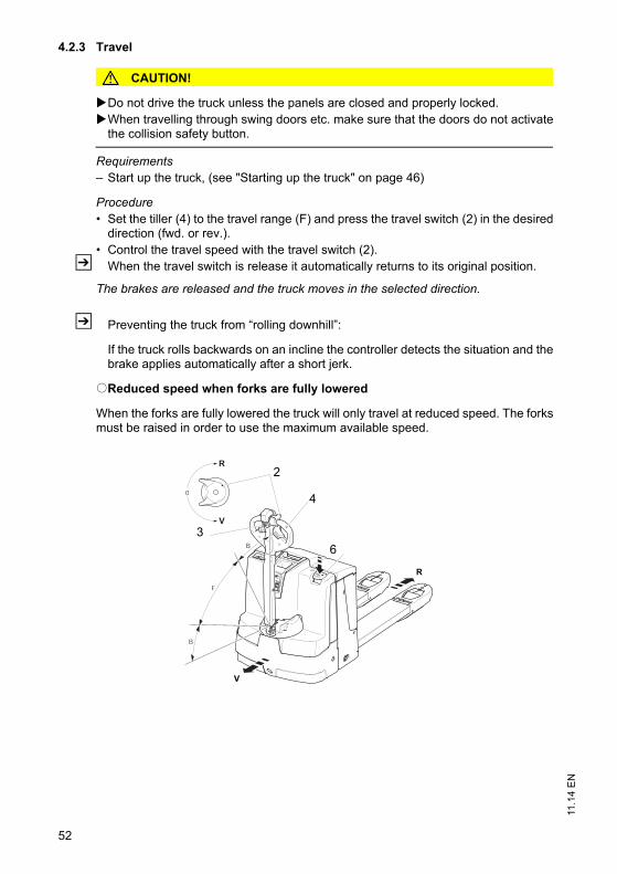
11.1
4 E
N
52
4.2.3 Travel
CAUTION!
Do not drive the truck unless the panels are closed and properly locked.When travelling through swing doors etc. make sure that the doors do not activate
the collision safety button.
Requirements– Start up the truck, (see "Starting up the truck" on page 46)
Procedure• Set the tiller (4) to the travel range (F) and press the travel switch (2) in the desired
direction (fwd. or rev.).• Control the travel speed with the travel switch (2).
Z When the travel switch is release it automatically returns to its original position.
The brakes are released and the truck moves in the selected direction.
Z Preventing the truck from “rolling downhill”:
If the truck rolls backwards on an incline the controller detects the situation and thebrake applies automatically after a short jerk.
oReduced speed when forks are fully lowered
When the forks are fully lowered the truck will only travel at reduced speed. The forksmust be raised in order to use the maximum available speed.
0
R
V
B
F
B
R
V
4
2
6
3

53
11.1
4 E
N4.2.4 Slow travel
CAUTION!
The driver must be particularly careful when applying the “slow travel speed”button (3).The brake is only activated when the "slow travel" button is released.In hazardous situations brake by immediately releasing the slow travel button (3)
and the travel switch (2).In "slow travel" you can only brake by inversion braking (travel switch (2)).
The truck can be operated with a vertical tiller (4) (e.g. in congested areas / travelseat).
Switching on slow travel
Procedure• Press the slow travel button (3).• Set the controller (2) to the required direction (fwd. or rev.).
The brake is released. The truck travels at slow speed.
Switching off slow travel
Procedure• Release the slow travel button (3).
In zone "B" the brake applies and the truck stops.In zone "F" the truck continues at slow travel.
• Release the travel switch (2).
Slow travel ends and the truck can now travel again at normal speed.
0
R
V
B
F
B
R
V
4
2
6
3
53
11.1
4 E
N
4.2.4 Slow travel
CAUTION!
The driver must be particularly careful when applying the “slow travel speed”button (3).The brake is only activated when the "slow travel" button is released.In hazardous situations brake by immediately releasing the slow travel button (3)
and the travel switch (2).In "slow travel" you can only brake by inversion braking (travel switch (2)).
The truck can be operated with a vertical tiller (4) (e.g. in congested areas / travelseat).
Switching on slow travel
Procedure• Press the slow travel button (3).• Set the controller (2) to the required direction (fwd. or rev.).
The brake is released. The truck travels at slow speed.
Switching off slow travel
Procedure• Release the slow travel button (3).
In zone "B" the brake applies and the truck stops.In zone "F" the truck continues at slow travel.
• Release the travel switch (2).
Slow travel ends and the truck can now travel again at normal speed.
0
R
V
B
F
B
R
V
4
2
6
3

11.1
4 E
N
54
4.2.5 Steering
Procedure• Move the tiller (4) to the left or right.
The truck is steered in the required direction.
11.1
4 E
N
54
4.2.5 Steering
Procedure• Move the tiller (4) to the left or right.
The truck is steered in the required direction.

55
11.1
4 E
N4.2.6 Brakes
The brake pattern of the truck depends largely on the travel route conditions. Thedriver must take this into account.
The truck can brake in the following ways:
– By inversion braking (travel switch)– Using the regenerative brake (coasting)– Emergency Disconnect switch– By setting the tiller to the "B" zone.
CAUTION!
In hazardous situations set the tiller to the brake position or press the EmergencyDisconnect switch.
Brakes
Procedure• Move the tiller (4) up or down to one of the brake
zones (B).Z Initially the truck brakes regeneratively. The
mechanical brake is only applied when this brakefails to achieve the necessary braking force.
The truck will decelerate at the maximum rate and thebrake will apply.
Inversion braking
Procedure• You can set the travel switch (2) to the opposite direction when travelling.
The truck brakes regeneratively until it starts to move in the opposite direction.
2 2
55
11.1
4 E
N
4.2.6 Brakes
The brake pattern of the truck depends largely on the travel route conditions. Thedriver must take this into account.
The truck can brake in the following ways:
– By inversion braking (travel switch)– Using the regenerative brake (coasting)– Emergency Disconnect switch– By setting the tiller to the "B" zone.
CAUTION!
In hazardous situations set the tiller to the brake position or press the EmergencyDisconnect switch.
Brakes
Procedure• Move the tiller (4) up or down to one of the brake
zones (B).Z Initially the truck brakes regeneratively. The
mechanical brake is only applied when this brakefails to achieve the necessary braking force.
The truck will decelerate at the maximum rate and thebrake will apply.
Inversion braking
Procedure• You can set the travel switch (2) to the opposite direction when travelling.
The truck brakes regeneratively until it starts to move in the opposite direction.
2 2

11.1
4 E
N
56
Regenerative braking
Procedure• If the travel switch is set to 0, the truck automatically brakes regeneratively.
The truck brakes to a halt regeneratively via the coasting brake. The brake thenapplies.
Z With regenerative braking energy is recuperated to the battery, ensuring a longerservice time.
4.3 Lifting, transporting and depositing loads
WARNING!
Unsecured and incorrectly positioned loads can cause accidents Before lifting a load unit the driver must make sure that it has been correctly palletisedand does not exceed the truck’s capacity.Instruct other people to move out of the hazardous area of the truck. Stop working
with the truck if people do not leave the hazardous area.Only carry loads that have been correctly secured and positioned. Use suitable
precautions to prevent parts of the load from tipping or falling down.Damaged loads must not be transported.Never exceed the maximum loads specified in the capacity chart.Never stand underneath a raised load handler.Do not stand on the load handler.Do not lift other people on the load handler.Insert the forks as far as possible underneath the load.
CAUTION!
Do not lift long loads at an angle.

57
11.1
4 E
N
Lifting load units
Requirements– Load unit correctly palletised.– Load unit weight matches the truck's
capacity.– Forks evenly loaded for heavy loads.
Procedure• Drive the truck carefully up to the pallet.• Slowly insert the forks into the pallet until the
fork shank touches the pallet.Z The load unit must not extend by more than
50 mm beyond the fork tips.• Press the “Lift” button (49) button until you
reach the desired lift height.
The load unit is raised.
CAUTION!
Release the button as soon as you reach the limit position of the load handler.
Transporting load units
Requirements– Load unit correctly lifted.– Mast lowered for transport (approx. 150 - 500 mm above the ground).– Good ground conditions.
Procedure• Accelerate and decelerate gradually.• Adapt your travel speed to the conditions of the route and the load you are
transporting.• Travel at a constant speed.• Watch out for other traffic at crossings and passageways. • Always travel with a lookout at blind spots.• On slopes and inclines always carry the load facing uphill, never approach at an
angle or turn.
48 49 49 48
48 494849

11.1
4 E
N
58
Depositing load units
NOTE
Loads must not be deposited on travel or escape routes, in front of safetymechanisms or operating equipment that must be accessible at all times.
Requirements– Warehouse location suitable for storing the load.
Procedure• Drive carefully up to the storage location.• Press the “Lower load handler” button (48).• Carefully lower the load handler so that the forks are clear of the load.• Carefully remove the forks from the pallet.
The load unit is lowered.

59
11.1
4 E
N5 Troubleshooting
This chapter enables the user to identify and rectify basic faults and the effects ofincorrect operation. When trying to locate a fault, proceed in the order shown in thetable.
Z If, after carrying out the following remedial action, the truck cannot be restored tooperation or if a fault in the electronics system is displayed with a correspondingerror code, contact the manufacturer’s service department.Additional troubleshooting must only be performed by the manufacturer’s specialistservice engineers. The manufacturer's customer service department is speciallytrained to carry out these operations.In order for customer services to react quickly and specifically to the fault, thefollowing information is essential:- Truck serial number- Error number on the display unit (if applicable)- Error description- Current location of truck
5.1 Truck does not start
5.2 Load cannot be lifted
Possible Cause Action
Battery connector not plugged in Check the battery connector and plug it in if necessary.
Emergency Disconnect pressed. Unlock the Emergency Disconnect
Key switch set to O. Set the key switch to “I”
Battery charge too low Check the battery charge and charge battery if necessary.
Faulty fuse Check fuses
Possible Cause Action
Truck not operational Carry out all measures listed under “Truck does not start”
Hydraulic oil level too low Check the hydraulic oil level
Battery discharge monitor has switched off
Charge the battery
Faulty fuse Check fuses
Excessive load Note maximum capacity, see data plate
59
11.1
4 E
N
5 Troubleshooting
This chapter enables the user to identify and rectify basic faults and the effects ofincorrect operation. When trying to locate a fault, proceed in the order shown in thetable.
Z If, after carrying out the following remedial action, the truck cannot be restored tooperation or if a fault in the electronics system is displayed with a correspondingerror code, contact the manufacturer’s service department.Additional troubleshooting must only be performed by the manufacturer’s specialistservice engineers. The manufacturer's customer service department is speciallytrained to carry out these operations.In order for customer services to react quickly and specifically to the fault, thefollowing information is essential:- Truck serial number- Error number on the display unit (if applicable)- Error description- Current location of truck
5.1 Truck does not start
5.2 Load cannot be lifted
Possible Cause Action
Battery connector not plugged in Check the battery connector and plug it in if necessary.
Emergency Disconnect pressed. Unlock the Emergency Disconnect
Key switch set to O. Set the key switch to “I”
Battery charge too low Check the battery charge and charge battery if necessary.
Faulty fuse Check fuses
Possible Cause Action
Truck not operational Carry out all measures listed under “Truck does not start”
Hydraulic oil level too low Check the hydraulic oil level
Battery discharge monitor has switched off
Charge the battery
Faulty fuse Check fuses
Excessive load Note maximum capacity, see data plate

11.1
4 E
N
60
6 Operating the truck without its own drive system
WARNING!
Uncontrolled truck movementWhen the brakes are de-activated the truck must be parked on a level surface, sincethe brakes are no longer effective.Do not release the brake on slopes or inclines.Apply the brake again when you reach your destination.Do not park the truck with the brake released.
Releasing the brake
Tools and Material Required– Two M5x45 screws– Spanner wrench
Procedure• Turn of the key switch, CanCode or ISM.• Switch off the Emergency Disconnect button.• Prevent the truck from rolling away.• Remove the front panel (11) and right-hand drive panel (50). (see "Industrial Truck
Maintenance" on page 75).• Pull up the anchor plate by screwing in two M5x45 screws (51) as far as the stop.
The brake is now released and the truck can be moved.
Applying the brake
Procedure• Unscrew the two M5x45 (51) screws again.• Refit the right hand drive panel (50).• Refit front panel (11).
Braking is now restored again.
51
11
50

61
11.1
4 E
N7 Optional equipment
7.1 Emergency operation with service key GF60
WARNING!
The truck can move accidentally when the brake is releasedThe GF60 service key must not remain on the truck during normal operation.The service key should only be used by an authorised person (e.g. warehouse
manager).Extreme caution is required on a ramp or incline as the truck could roll away when
the brake is released.When the key switch is set to position 2 (brake released), the truck cannot brake
through inversion braking or the tiller switch.
Operating the truck without its own drive system.
Requirements– Truck prevented from rolling away. – Charged battery in truck.
Tools and Material Required– GF60 service key with lock bar
Procedure• Insert the GF60 service key in the key switch.
Z The service key GF60 with a lock bar can only be inserted and turned on one side.If inserted in the wrong direction the key will not turn.
• Turn service key to position 1.• Move the lock bar on the head of the key.• Turn service key to position 2.
CAUTION!The brake is now releasedThe truck can only brake by turning the service key to position 1 or pressing the
Emergency Disconnect.
The truck can be operated without its own drive system.
GF 60
61
11.1
4 E
N
7 Optional equipment
7.1 Emergency operation with service key GF60
WARNING!
The truck can move accidentally when the brake is releasedThe GF60 service key must not remain on the truck during normal operation.The service key should only be used by an authorised person (e.g. warehouse
manager).Extreme caution is required on a ramp or incline as the truck could roll away when
the brake is released.When the key switch is set to position 2 (brake released), the truck cannot brake
through inversion braking or the tiller switch.
Operating the truck without its own drive system.
Requirements– Truck prevented from rolling away. – Charged battery in truck.
Tools and Material Required– GF60 service key with lock bar
Procedure• Insert the GF60 service key in the key switch.
Z The service key GF60 with a lock bar can only be inserted and turned on one side.If inserted in the wrong direction the key will not turn.
• Turn service key to position 1.• Move the lock bar on the head of the key.• Turn service key to position 2.
CAUTION!The brake is now releasedThe truck can only brake by turning the service key to position 1 or pressing the
Emergency Disconnect.
The truck can be operated without its own drive system.
GF 60

11.1
4 E
N
62
Parking the truck securely
Procedure• Set the key switch to the “0” position and remove the key.
Z When you switch back from level 2 to level 1 the bar returns to its original position.
The brake is now activated again.
Z The GF30 key without a bar is designed for normal truck operation.It can be inserted on either side and can only be turned to position 1of the key switch.
GF 30

63
11.1
4 E
N7.2 CanCode keypad
CanCode keypad
The keypad consists of 10 digit keys, a Set key and a okey.
The O key indicates the follow operating statuses via ared / green LED:– Code lock function (starting up the truck).– Adjusting the travel program depending on the setting
and truck.– Setting and changing parameters.
7.2.1 Keypad
When the correct code is entered, the truck is ready for use. You can allocate anindividual code to each truck, operator or group of operators. When the truck issupplied from the factory, the code is indicated on a sticker. Change the master andoperator codes when you use the truck for the first time.
Z Set different codes for rider and pedestrian trucks.
Starting the truck
Procedure• Switching on the Emergency
Disconnect.LED (57) lights up red.
• Enter the code.When you enter the correct operatorcode the LED (57) turns green. If theLED (57) flashes red this means thewrong code has been entered. Tryagain.
The truck is switched on
Z The Set key (56) has no function in operating mode.
Switching the truck off
Procedure• Press the O key.
The truck is switched off.
Z The truck can switch off automatically after a set time. To do this the relevant codelock parameters must be entered, (see "Parameter Settings" on page 64).
7.2.2 Parameters
The keypad enables parameters to be adjusted in programming mode.
1 2 3
4 5 6
7 8 9
0Set
1 2 3
4 5 6
7 8 9
0Set56
52 53 54
55
57
63
11.1
4 E
N
7.2 CanCode keypad
CanCode keypad
The keypad consists of 10 digit keys, a Set key and a okey.
The O key indicates the follow operating statuses via ared / green LED:– Code lock function (starting up the truck).– Adjusting the travel program depending on the setting
and truck.– Setting and changing parameters.
7.2.1 Keypad
When the correct code is entered, the truck is ready for use. You can allocate anindividual code to each truck, operator or group of operators. When the truck issupplied from the factory, the code is indicated on a sticker. Change the master andoperator codes when you use the truck for the first time.
Z Set different codes for rider and pedestrian trucks.
Starting the truck
Procedure• Switching on the Emergency
Disconnect.LED (57) lights up red.
• Enter the code.When you enter the correct operatorcode the LED (57) turns green. If theLED (57) flashes red this means thewrong code has been entered. Tryagain.
The truck is switched on
Z The Set key (56) has no function in operating mode.
Switching the truck off
Procedure• Press the O key.
The truck is switched off.
Z The truck can switch off automatically after a set time. To do this the relevant codelock parameters must be entered, (see "Parameter Settings" on page 64).
7.2.2 Parameters
The keypad enables parameters to be adjusted in programming mode.
1 2 3
4 5 6
7 8 9
0Set
1 2 3
4 5 6
7 8 9
0Set56
52 53 54
55
57

11.1
4 E
N
64
Parameter Groups
The parameter number is composed of three digits. The first digit refers to theparameter group as shown in Table 1. The second and third digits are numbered insequence from 00 to 99.
7.2.3 Parameter Settings
To change the truck settings you must enter the master code.
Z The master code factory setting is 7-2-9-5. Change the master code the first timeyou use the truck.
Z Set different codes for rider and pedestrian trucks.
Changing the truck settings
Procedure• Press the O key (55).• Enter the master code.• Enter the three-digit parameter number. • Confirm with the SET key (56).• Enter the setting as per parameter list.
Z If the entry is incorrect, the LED (57) of the O key (55) turns red. • Enter the parameter number again.• Enter the setting again or change it.
• Confirm with the SET key (56).• Repeat the procedure for other parameters.• Then press the O key (55).
The settings are now saved.
No. Parameter Groups0XX Code lock settings (codes, travel program release, automatic cutout, etc.)

65
11.1
4 E
NParameter list
No. Function Setting range Standard setting
Procedure
000 Change master code: The length (4-6 digits) of the master code also determines the length of the operator code (4-6 digits). Provided the operator codes are programmed, only new codes of the same length can be entered. If you wish to change the code length, you must first delete all the operator codes.
0000 - 9999 or
00000 - 99999 or
000000 - 999999
7295 – (LED 52 flashes) Confirm current code entry
–(Set 56)
– (LED 53 flashes)Enter a new code
–(Set 56)
– (LED 54 flashes) repeat new code
–(Set 56)
001 Add code (max. 250) 0000 - 9999 or
00000 - 99999 or
000000 - 999999
2580 – (LED 53 flashes)Confirm code entry
–(Set 56)
– (LED 54 flashes) repeat code entry
–(Set 56)
002 Change code 0000 - 9999 or
00000 - 99999 or
000000 - 999999
– (LED 52 flashes)Confirm current code entry
–(Set 56)
– (LED 53 flashes)Confirm new code entry
–(Set 56)
– (LED 54 flashes)Confirm code re-entry
–(Set 56)
LEDs 52-54 are located in keypads 1-3.
65
11.1
4 E
N
Parameter list
No. Function Setting range Standard setting
Procedure
000 Change master code: The length (4-6 digits) of the master code also determines the length of the operator code (4-6 digits). Provided the operator codes are programmed, only new codes of the same length can be entered. If you wish to change the code length, you must first delete all the operator codes.
0000 - 9999 or
00000 - 99999 or
000000 - 999999
7295 – (LED 52 flashes) Confirm current code entry
–(Set 56)
– (LED 53 flashes)Enter a new code
–(Set 56)
– (LED 54 flashes) repeat new code
–(Set 56)
001 Add code (max. 250) 0000 - 9999 or
00000 - 99999 or
000000 - 999999
2580 – (LED 53 flashes)Confirm code entry
–(Set 56)
– (LED 54 flashes) repeat code entry
–(Set 56)
002 Change code 0000 - 9999 or
00000 - 99999 or
000000 - 999999
– (LED 52 flashes)Confirm current code entry
–(Set 56)
– (LED 53 flashes)Confirm new code entry
–(Set 56)
– (LED 54 flashes)Confirm code re-entry
–(Set 56)
LEDs 52-54 are located in keypads 1-3.

11.1
4 E
N
66
Assigning the starting travel program (depending on the truck)
The travel programs are connected to the code. The travel programs can beindividually released or blocked for each code. A starting travel program can beassigned to each code.
Once a user code has been set up, all travel programs are globally released, the validstart travel program is travel program 2.The code configuration can then be changed with program number 024.
1. digit: travel program 1 release (0 = blocked or 1 = released) 2nd digit: travel program 2 release (0 = blocked or 1 = released) 3rd digit: travel program 3 release (0 = blocked or 1 = released) 4th digit: start travel program (0, 1, 2 or 3)
003 Delete code 0000 - 9999 or
00000 - 99999 or
000000 - 999999
– (LED 53 flashes)Confirm new code entry
–(Set 56)
– (LED 54 flashes) repeat code entry
–(Set 56)
004 Delete code log (deletes all codes)
3265 – 3265 = delete– other inputs = do
not delete
010 Automatic timeout 00-31 00 – 00 = No timeout– 01 - 30 = Timeout
in minutes– 31 = Timeout after
10 seconds
No. Function Setting range Standard setting
Procedure
LEDs 52-54 are located in keypads 1-3.
No. Function Setting range Standard setting
Procedure
024 Code configuration 1112

67
11.1
4 E
N
Setting the travel program configuration to a code
Procedure• Press the O key (55).• Enter the master code.• Enter the three-digit parameter number 024. • Confirm with the SET key (56).• Enter the code to be changed and confirm with SET.• Enter the configuration (4 digit) and confirm with SET.• Enter the configuration (4 digit) again and confirm with SET.• Repeat the procedure for other codes.• Then press the O key.
The travel programs are assigned to the codes
Keypad event messages
The LED (57) flashes red to indicate the following events:– New master code is already in use.– New code is already the master code– Code to be changed does not exist– Attempt to change the code to one that already exists.– Attempt to delete a code that does not exist– Code memory full.

11.1
4 E
N
68
7.3 Setting the truck parameters with CanCode
CAUTION!
Faulty entryWithout CanDis only CanCode internal parameters can be changed. Tractioncontroller parameters can only be changed with CanDis, without CanDis the settingsmust be performed by the manufacturer's service department.
CAUTION!
Altering travel parameters can cause accidentsIncreasing the settings for acceleration, steering, travel, lifting and lowering can resultin accidents. Carry out a test run in a secure environment.This requires greater attention on the part of the operator.
Parameter setting example:
The following example shows the parameter setting for the acceleration of travelprogram 1 (parameter 0256).
Acceleration example
Procedure• Enter four-digit parameter number "0256" and confirm with the SET key (56).• Enter sub-index (enter "2") and confirm with the SET key (56).
Z The parameter and sub index are displayed alternately with the current reading(0256-2<->0000-3).
• Enter the parameter according to the parameter list and confirm with the Set key(56).
Z The LED (57) of the O key (55) switches briefly to steady light and start flashingagain after approx. 2 seconds.
Z If the entry is incorrect, the LED (57) of the O key (55) turns red. Enter theparameter number again to repeat the setting.
Z The parameter and sub index are displayed alternately with the current reading(0256-2<->0000-5).
The travel parameter is now set.
Repeat the procedure to enter further parameters as soon as the LED (57) of the Okey (55) flashes.
Z Travel is disabled while the parameters are being entered.
Checking the settings in programming mode
Procedure• Select the travel program to be worked on after changing the parameter value, and
confirm with the Set key (56).
The truck is now in travel mode and can be checked.

69
11.1
4 E
NZ To continue setting, confirm with the Set key (56) again.
Saving travel parameters
Requirements– Enter all parameters.
Procedure• Run "SaveParameters" by pressing 1-2-3-Set.• Confirm with the O key (55).
69
11.1
4 E
N
Z To continue setting, confirm with the Set key (56) again.
Saving travel parameters
Requirements– Enter all parameters.
Procedure• Run "SaveParameters" by pressing 1-2-3-Set.• Confirm with the O key (55).

11.1
4 E
N
70
7.4 Parameters
Travel program 1
Travel program 2
Travel program 3
No. Function Setting range Standard setting
Comments
0256 Acceleration 0 - 9(0.2 – 2.0 m/s2)
2(0.6 m/s2)
0260 Coasting brake 0 - 9(0.2 – 1.1 m/s2)
6(0.8 m/s2)
0264 Maximum speed in drive direction via controller
0 - 9(0.5 - 6.0 km/h)
6(4.8 km/h)
depending on travel switch
0268 Maximum speed in fork direction via controller
0 - 9(0.5 - 6.0 km/h)
6(4.8 km/h)
depending on travel switch
No. Function Setting range Standard setting
Comments
0272 Acceleration 0 - 9(0.2 – 2.0 m/s2)
5(1.2 m/s2)
0276 Coasting brake 0 - 9(0.2 – 1.1 m/s2)
6(0.8 m/s2)
0280 Maximum speed in tiller direction via controller
0 - 9(0.5 - 6.0 km/h)
9(6.0 km/h)
depending on travel switch
0284 Maximum speed in fork direction via controller
0 - 9(0.5 - 6.0 km/h)
9(6.0 km/h)
depending on travel switch
No. Function Setting range Standard setting
Comments
0288 Acceleration 0 - 9(0.2 – 2.0 m/s2)
9(2.0 m/s2)
0292 Coasting brake 0 - 9(0.2 – 1.1 m/s2)
9(1.1 m/s2)
0296 Maximum speed in tiller direction via controller
0 - 9(0.5 - 6.0 km/h)
9(6.0 km/h)
depending on travel switch
0300 Maximum speed in fork direction via controller
0 - 9(0.5 - 6.0 km/h)
9(6.0 km/h)
depending on travel switch

71
11.1
4 E
N
Battery parameters
No. Function Setting range
Standard setting
Comments
1377 Battery type (normal / high performance / dry)
0 - 2 1 0 = Normal (wet)
1 = High performance (wet)
2 = Dry (maintenance-free)
1389 Discharge monitor function
0 /1 1 0 = Not active1 = Active
71
11.1
4 E
N
Battery parameters
No. Function Setting range
Standard setting
Comments
1377 Battery type (normal / high performance / dry)
0 - 2 1 0 = Normal (wet)
1 = High performance (wet)
2 = Dry (maintenance-free)
1389 Discharge monitor function
0 /1 1 0 = Not active1 = Active

11.1
4 E
N
72
7.5 CANDIS display instrument
The instrument indicates:
In addition, service messages for the electronic components and parameter changesare displayed.
Discharge status display
Setting limits for the additional “Warning” (60) and “Stop” (61) displays will depend onthe battery type.
The available capacity is shown via 8 LED bars.
The current battery capacity is shown by the illuminated LED bars. 8 bars correspondto full battery capacity, 1 bar corresponds to the minimum available capacity.
If only one LED bar is lit, the battery capacity is almost depleted and the “Warning”indicator (60) is lit. The battery must be charged immediately.
If no more LED bars are illuminated, the “Stop” indicator (61) lights up. Lifting is nowinhibited. The battery must be charged.
7.5.1 Discharge monitor function
When the discharge monitor function is enabled, lifting is cut out when reaching thedischarge limit is reached (the Stop LED goes on). Travel and lowering are stillpossible.
58Battery charge display (on board charger only)
59Capacity display barsBattery residual charge status
60Warning - pre-warning symbol,Battery charge recommended
61Stop symbol; lift cutout,Battery charge required
62T symbol appears during operation when the discharge indicator is set to maintenance-free battery
636 digit LCD display;hourmeter, input display;error display
58
60
62
59
61
63
11.1
4 E
N
72
7.5 CANDIS display instrument
The instrument indicates:
In addition, service messages for the electronic components and parameter changesare displayed.
Discharge status display
Setting limits for the additional “Warning” (60) and “Stop” (61) displays will depend onthe battery type.
The available capacity is shown via 8 LED bars.
The current battery capacity is shown by the illuminated LED bars. 8 bars correspondto full battery capacity, 1 bar corresponds to the minimum available capacity.
If only one LED bar is lit, the battery capacity is almost depleted and the “Warning”indicator (60) is lit. The battery must be charged immediately.
If no more LED bars are illuminated, the “Stop” indicator (61) lights up. Lifting is nowinhibited. The battery must be charged.
7.5.1 Discharge monitor function
When the discharge monitor function is enabled, lifting is cut out when reaching thedischarge limit is reached (the Stop LED goes on). Travel and lowering are stillpossible.
58Battery charge display (on board charger only)
59Capacity display barsBattery residual charge status
60Warning - pre-warning symbol,Battery charge recommended
61Stop symbol; lift cutout,Battery charge required
62T symbol appears during operation when the discharge indicator is set to maintenance-free battery
636 digit LCD display;hourmeter, input display;error display
58
60
62
59
61
63
73
11.1
4 E
N7.5.2 Service hours display
Display range between 0.0 and 99,999.0 hours. Travel and lifting operations arelogged. This is a backlit display.
Z For maintenance-free batteries a “T” symbol is shown in the hourmeterdisplay (62).
7.5.3 Event messages
The service hours display is also used to display event messages. The error displaystarts with an ”E” for Event and a four-digit error number.If several events occur simultaneously, they are displayed one after the other. Theevents are displayed until they are rectified. Event messages overwrite the servicehour display. Most events cause the Emergency Stop to be activated. Events remaindisplayed until the control circuit is switched off (key switch).
If no CanDis is present, the event code is displayed by the flashing of the dischargemonitor LED.
Z The manufacturer’s service department has detailed component descriptions withevent codes.
7.5.4 Power up test
On power up the display shows:
– the software version of the display instrument (briefly),– the service hours,– the battery charge status.
7.6 ISM access module (o)
Z If the truck is equipped with an ISM access module or Can Code refer to the “ISMAccess Module” operator manual.
73
11.1
4 E
N
7.5.2 Service hours display
Display range between 0.0 and 99,999.0 hours. Travel and lifting operations arelogged. This is a backlit display.
Z For maintenance-free batteries a “T” symbol is shown in the hourmeterdisplay (62).
7.5.3 Event messages
The service hours display is also used to display event messages. The error displaystarts with an ”E” for Event and a four-digit error number.If several events occur simultaneously, they are displayed one after the other. Theevents are displayed until they are rectified. Event messages overwrite the servicehour display. Most events cause the Emergency Stop to be activated. Events remaindisplayed until the control circuit is switched off (key switch).
If no CanDis is present, the event code is displayed by the flashing of the dischargemonitor LED.
Z The manufacturer’s service department has detailed component descriptions withevent codes.
7.5.4 Power up test
On power up the display shows:
– the software version of the display instrument (briefly),– the service hours,– the battery charge status.
7.6 ISM access module (o)
Z If the truck is equipped with an ISM access module or Can Code refer to the “ISMAccess Module” operator manual.

11.1
4 E
N
74
11.1
4 E
N
74

75
11.1
4 E
N
F Industrial Truck Maintenance
1 Operational Safety and Environmental Protection
The checks and servicing operations contained in this chapter must be performed inaccordance with the intervals as indicated in the servicing checklists.
WARNING!
Risk of accidents and damage to componentsAll modifications to the forklift truck assemblies, in particular the safety mechanisms,are prohibited. The operating speeds of the truck must not be increased under anycircumstances.
NOTE
Only original spare parts have been certified by our quality assurance department. Toensure safe and reliable operation of the truck, use only the manufacturer's spareparts.For safety reasons, only components which have been specially agreed by themanufacturer for this truck may be installed near the computer, controllers and wireguidance sensors (antennae). These components (computers, controllers, wireguidance sensors (antennae)) must therefore not be replaced either by similarcomponents from other trucks of the same series.
2 Maintenance Safety Regulations
Maintenance personnel
The truck should only be serviced and repaired by the manufacturer's specialistcustomer service personnel who have been trained to do this. We thereforerecommend that you enter into a maintenance contract with the manufacturer’s localsales office.

11.1
4 E
N
76
Lifting and jacking up
WARNING!
Lifting and jacking up the truck safelyIn order to raise the truck, the lifting gear must only be secured to the points speciallyprovided for this purpose. You may only work under a raised load handler / raised cab if they have been securedwith a sufficiently strong chain or the fastening bolt.In order to raise and jack up the truck safely, proceed as follows:Jack up the truck only on a level surface and prevent it from moving accidentally.Always use a jack with sufficient capacity. When jacking up the truck, take
appropriate measures to prevent it from slipping or tipping over (e.g. wedges,wooden blocks).
In order to raise the truck, the lifting gear must only be secured to the pointsspecially provided for this purpose, (see "Transport and Commissioning" onpage 23).
When jacking up the truck, take appropriate measures to prevent it from slipping ortipping over (e.g. wedges, wooden blocks).
Cleaning
CAUTION!
Fire hazardDo not use flammable liquids to clean the industrial truck.Always disconnect the battery before starting cleaning work.Carry out all necessary safety measures to prevent sparking before cleaning (e.g.
by short-circuiting).
CAUTION!
Risk of electrical system damageThe electrical system can be damaged if it is cleaning with water. It is prohibited toclean the electrical system with water.Do not clean the electrical system with water.Clean the electrical system with weak suction or compressed air (use a compressor
with a water trap) and not a conductive, anti-static brush.
CAUTION!
Risk of component damage when cleaning the truckIf the truck is to be cleaned with a water jet or a high-pressure cleaner, all electricaland electronic components must be carefully covered beforehand as moisture cancause malfunctions. Do not clean with pressurised water.
Z After cleaning, carry out the operations detailed in “Recommissioning the truck aftercleaning or maintenance work” ((see "Restoring the truck to service aftermaintenance and repairs" on page 91)).

77
11.1
4 E
NElectrical system
WARNING!
Accident riskOnly suitably trained electricians may operate on the truck's electrical system.Before working on the electrical system, take all precautionary measures to avoid
electric shocks.Always disconnect the battery before starting cleaning operations.
WARNING!
Electric currents can cause accidentsMake sure the electrical system is voltage-free before starting work on it. Beforestarting maintenance on the electrical system:Park the truck securely ((see "Parking the truck securely" on page 48)).Press the Emergency Disconnect. Disconnect the battery.Remove any rings or metal bracelets etc. before working on electrical components.
Consumables and used parts
CAUTION!
Consumables and used parts are an environmental hazardUsed parts, oils and fuels must be disposed of in accordance with the relevantenvironmental protection regulations. To change the oil contact the manufacturer'scustomer service department, who have been specially trained for this task.Note the safety regulations when handling these materials.
Welding
Remove electrical and electronic components from the truck before performingwelding operations, to avoid damage.
Settings
When repairing or replacing hydraulic, electric or electronic components orassemblies, always note the truck-specific settings.
Wheels
WARNING!
The use of wheels that do not match the manufacturer's specifications canresult in accidents.The quality of wheels affects the stability and performance of the truck. Uneven wear affects the truck's stability and increases the stopping distance. When replacing wheels make sure the truck is not skewed.Always replace wheels in pairs, i.e. left and right at the same time.
77
11.1
4 E
N
Electrical system
WARNING!
Accident riskOnly suitably trained electricians may operate on the truck's electrical system.Before working on the electrical system, take all precautionary measures to avoid
electric shocks.Always disconnect the battery before starting cleaning operations.
WARNING!
Electric currents can cause accidentsMake sure the electrical system is voltage-free before starting work on it. Beforestarting maintenance on the electrical system:Park the truck securely ((see "Parking the truck securely" on page 48)).Press the Emergency Disconnect. Disconnect the battery.Remove any rings or metal bracelets etc. before working on electrical components.
Consumables and used parts
CAUTION!
Consumables and used parts are an environmental hazardUsed parts, oils and fuels must be disposed of in accordance with the relevantenvironmental protection regulations. To change the oil contact the manufacturer'scustomer service department, who have been specially trained for this task.Note the safety regulations when handling these materials.
Welding
Remove electrical and electronic components from the truck before performingwelding operations, to avoid damage.
Settings
When repairing or replacing hydraulic, electric or electronic components orassemblies, always note the truck-specific settings.
Wheels
WARNING!
The use of wheels that do not match the manufacturer's specifications canresult in accidents.The quality of wheels affects the stability and performance of the truck. Uneven wear affects the truck's stability and increases the stopping distance. When replacing wheels make sure the truck is not skewed.Always replace wheels in pairs, i.e. left and right at the same time.

11.1
4 E
N
78
Z When replacing wheels fitted at the factory, only use the manufacturer’s originalspare parts. Otherwise the truck's rated performance cannot be ensured.
Hydraulic hoses
WARNING!
Leaky hydraulic systems can result in accidentsHydraulic oil can escape from leaky and faulty hydraulic systems.Report any defects immediately to your supervisor.Mark defective truck and take out of service.Do not return the industrial truck to service until you have identified and rectified the
fault.Remove any spilled hydraulic immediately with an appropriate bonding agent.The bonding agent / consumable mixture must be disposed of in accordance with
regulations.
WARNING!
Faulty hydraulic hoses can result in injury and infectionPressurised hydraulic oil can escape from fine holes or hairline cracks in the hydraulichoses. Brittle hydraulic hoses can burst during operation. People standing near thetruck can be injured by the hydraulic oil.Call for a doctor immediately in the event of an injury.Do not touch pressurised hydraulic hoses. Report any defects immediately to your supervisor.Mark defective truck and take it out of service.Do not return the industrial truck to service until you have identified and rectified the
fault.
NOTE
Testing and replacing hydraulic hosesHydraulic hoses can become brittle through age and must be checked at regularintervals. The application conditions of the industrial truck have a considerable impacton the ageing of the hydraulic hoses.Check the hydraulic hoses at least annually and replace if necessary.If the operating conditions become more arduous the inspection intervals must be
reduced accordingly.In normal operating conditions a precautionary replacement of the hydraulic hoses
is recommended after 6. The owner must carry out a risk assessment to ensuresafe, prolonged use. The resulting protection measures must be observed and theinspection interval reduced accordingly.

79
11.1
4 E
N3 Servicing and Inspection
Thorough and expert servicing is one of the most important requirements for the safeoperation of the industrial truck. Failure to perform regular servicing can lead to truckfailure and poses a potential hazard to personnel and equipment.
WARNING!
The application conditions of an industrial truck have a considerable impact on thewear of the service components.We recommend that a Jungheinrich customer service adviser carries out anapplication analysis on site to work out specific service intervals to prevent damagedue to wear.The service intervals stated are based on single shift operation under normaloperating conditions. They must be reduced accordingly if the truck is to be used inconditions of extreme dust, temperature fluctuations or multiple shifts.
The following servicing checklist indicates the operations to be performed and therespective intervals to be observed. Maintenance intervals are defined as:
Z W maintenance intervals must be performed by the owner.
During the run-in period – after approx. 100 service hours – the owner must check thewheel nuts / bolts and re-tighten if necessary.
W = Every 50 service hours, at least weekly
A = Every 500 service hours
B = Every 1000 service hours, or at least annually
C = Every 2000 service hours, or at least annually
t = Standard maintenance interval
k =Cold store maintenance interval (in addition to standard maintenance interval)
79
11.1
4 E
N
3 Servicing and Inspection
Thorough and expert servicing is one of the most important requirements for the safeoperation of the industrial truck. Failure to perform regular servicing can lead to truckfailure and poses a potential hazard to personnel and equipment.
WARNING!
The application conditions of an industrial truck have a considerable impact on thewear of the service components.We recommend that a Jungheinrich customer service adviser carries out anapplication analysis on site to work out specific service intervals to prevent damagedue to wear.The service intervals stated are based on single shift operation under normaloperating conditions. They must be reduced accordingly if the truck is to be used inconditions of extreme dust, temperature fluctuations or multiple shifts.
The following servicing checklist indicates the operations to be performed and therespective intervals to be observed. Maintenance intervals are defined as:
Z W maintenance intervals must be performed by the owner.
During the run-in period – after approx. 100 service hours – the owner must check thewheel nuts / bolts and re-tighten if necessary.
W = Every 50 service hours, at least weekly
A = Every 500 service hours
B = Every 1000 service hours, or at least annually
C = Every 2000 service hours, or at least annually
t = Standard maintenance interval
k =Cold store maintenance interval (in addition to standard maintenance interval)

11.1
4 E
N
80
4 Maintenance checklist
4.1 Owner
4.1.1 Standard equipment
Brakes W A B C
1 Test brakes. t
Electrical System W A B C
1Test warning and safety devices in accordance with operating instructions.
t
2 Test Emergency Disconnect switch. t
Power Supply W A B C
1 Check battery and battery components. t
2Check battery cable connections are secure, grease terminals if necessary.
t
3Check battery connector for damage, test it and make sure it is secure.
t
Travel W A B C
1 Check wheels for wear and damage. t
Chassis and Superstructure W A B C
1 Check doors and/or covers. t2 Check labels are legible and complete. t
Hydraulic operations W A B C
1 Check forks or load handler for wear and damage. t2 Test hydraulic system. t3 Check hydraulic oil level and top up if necessary. t
Steering W A B C
1 Check tiller recuperating function. t

81
11.1
4 E
N4.2 Customer Service
4.2.1 Standard equipment
Brakes W A B C
1 Test brakes. t2 Check magnetic brake air gap. t
Electrical System W A B C
1 Test displays and controls. t
2Test warning and safety devices in accordance with operating instructions.
t
3 Check fuse ratings. t
4Check electric wiring for damage [insulation damage, connections]. Make sure wire connections are secure.
t
5 Test micro switch and adjust if necessary. t6 Check contactors and/or relays. t7 Carry out a frame leakage test. t8 Test cable and motor attachments. t9 Test Emergency Disconnect switch. t
Power Supply W A B C
1 Check battery and battery components. t
2Check battery cable connections are secure, grease terminals if necessary.
t
3 Check acid density and battery voltage. t
4Check battery connector for damage, test it and make sure it is secure.
t
Travel W A B C
1 Check transmission for noise and leakage. t2 Check wheel suspension and attachment. t3 Check wheels for wear and damage. t4 Checking bedding and attachment of the drive system. t5 Note: Replace transmission oil after 10000 service hours.
Chassis and Superstructure W A B C
1 Check doors and/or covers. t2 Check labels are legible and complete. t3 Check chassis and screw connections for damage. t
81
11.1
4 E
N
4.2 Customer Service
4.2.1 Standard equipment
Brakes W A B C
1 Test brakes. t2 Check magnetic brake air gap. t
Electrical System W A B C
1 Test displays and controls. t
2Test warning and safety devices in accordance with operating instructions.
t
3 Check fuse ratings. t
4Check electric wiring for damage [insulation damage, connections]. Make sure wire connections are secure.
t
5 Test micro switch and adjust if necessary. t6 Check contactors and/or relays. t7 Carry out a frame leakage test. t8 Test cable and motor attachments. t9 Test Emergency Disconnect switch. t
Power Supply W A B C
1 Check battery and battery components. t
2Check battery cable connections are secure, grease terminals if necessary.
t
3 Check acid density and battery voltage. t
4Check battery connector for damage, test it and make sure it is secure.
t
Travel W A B C
1 Check transmission for noise and leakage. t2 Check wheel suspension and attachment. t3 Check wheels for wear and damage. t4 Checking bedding and attachment of the drive system. t5 Note: Replace transmission oil after 10000 service hours.
Chassis and Superstructure W A B C
1 Check doors and/or covers. t2 Check labels are legible and complete. t3 Check chassis and screw connections for damage. t
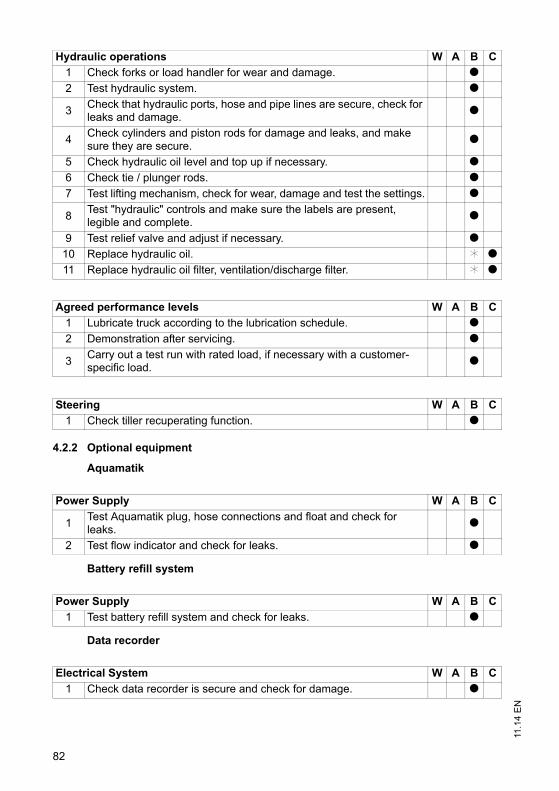
11.1
4 E
N
82
4.2.2 Optional equipment
Aquamatik
Battery refill system
Data recorder
Hydraulic operations W A B C
1 Check forks or load handler for wear and damage. t2 Test hydraulic system. t
3Check that hydraulic ports, hose and pipe lines are secure, check for leaks and damage.
t
4Check cylinders and piston rods for damage and leaks, and make sure they are secure.
t
5 Check hydraulic oil level and top up if necessary. t6 Check tie / plunger rods. t7 Test lifting mechanism, check for wear, damage and test the settings. t
8Test "hydraulic" controls and make sure the labels are present, legible and complete.
t
9 Test relief valve and adjust if necessary. t10 Replace hydraulic oil. k t11 Replace hydraulic oil filter, ventilation/discharge filter. k t
Agreed performance levels W A B C
1 Lubricate truck according to the lubrication schedule. t2 Demonstration after servicing. t
3Carry out a test run with rated load, if necessary with a customer-specific load.
t
Steering W A B C
1 Check tiller recuperating function. t
Power Supply W A B C
1Test Aquamatik plug, hose connections and float and check for leaks.
t
2 Test flow indicator and check for leaks. t
Power Supply W A B C
1 Test battery refill system and check for leaks. t
Electrical System W A B C
1 Check data recorder is secure and check for damage. t

83
11.1
4 E
NOn-board charger
Entry skids / rollers
Load backrest
Impact sensor
Lateral battery removal
Access module
Charger W A B C
1 Check mains connector and mains cable. t
2Check the start-up protection system for trucks with an on-board charger.
t
3Check the wires and electrical connections are secure and not damaged.
t
4 Potential measurement on chassis while charging is in progress. t
Hydraulic operations W A B C
1Check entry skids or entry rollers for damage and wear, and test operation.
t
Hydraulic operations W A B C
1Check attachment is properly secured to the truck and the supporting elements.
t
Electrical System W A B C
1 Check impact sensor is secure and check for damage. t
Power Supply W A B C
1 Test battery lock / battery attachment. t
Electrical System W A B C
1 Test access module, check for damage and make sure it is secure. t
83
11.1
4 E
N
On-board charger
Entry skids / rollers
Load backrest
Impact sensor
Lateral battery removal
Access module
Charger W A B C
1 Check mains connector and mains cable. t
2Check the start-up protection system for trucks with an on-board charger.
t
3Check the wires and electrical connections are secure and not damaged.
t
4 Potential measurement on chassis while charging is in progress. t
Hydraulic operations W A B C
1Check entry skids or entry rollers for damage and wear, and test operation.
t
Hydraulic operations W A B C
1Check attachment is properly secured to the truck and the supporting elements.
t
Electrical System W A B C
1 Check impact sensor is secure and check for damage. t
Power Supply W A B C
1 Test battery lock / battery attachment. t
Electrical System W A B C
1 Test access module, check for damage and make sure it is secure. t

11.1
4 E
N
84
5 Lubricants and Lubrication Schedule
5.1 Handling consumables safely
Handling consumables
Consumables must always be handled correctly. Follow the manufacturer’sinstructions.
WARNING!
Improper handling is hazardous to health, life and the environmentConsumables can be flammable.Keep consumables away from hot components and naked flames.Always keep consumables in prescribed containers.Always fill consumables in clean containers.Do not mix up different grades of consumable. The only exception to this is when
mixing is expressly stipulated in the operating instructions.
CAUTION!
Spilled liquids can cause slipping and endanger the environmentRisk of slipping from spilled liquids. The risk is greater when combined with water.Do not spill fluids.Spilled fluids must be removed immediately with an appropriate bonding agent.The bonding agent / consumable mixture must be disposed of in accordance with
regulations.
WARNING!
Oils (chain spray / hydraulic oil) are flammable and poisonous.Dispose of used oils in accordance with regulations. Store used oil safely until it can
be disposed of in accordance with regulations.Do not spill oil.Spilled fluids must be removed immediately with an appropriate bonding agent.The bonding agent / consumable mixture must be disposed of in accordance with
regulations.Observe national regulations when handling oils.Wear safety gloves when handling oils.Prevent oil from coming into contact with hot motor parts.Do not smoke when handling oil.Avoid contact and digestion. If you swallow oil do not induce vomiting but call for a
doctor immediately.Seek fresh air after breathing in oil fumes or vapours.If oil has come into contact with your skin, rinse your skin with water.If oil has come into contact with your eyes, rinse them with water and call for a
doctor immediately.Replace oil-soaked clothing and shoes immediately.

85
11.1
4 E
NConsumables and used parts
CAUTION!
Consumables and used parts are an environmental hazardUsed parts, oils and fuels must be disposed of in accordance with the relevantenvironmental protection regulations. To change the oil contact the manufacturer'scustomer service department, who have been specially trained for this task.Note the safety regulations when handling these materials.
85
11.1
4 E
N
Consumables and used parts
CAUTION!
Consumables and used parts are an environmental hazardUsed parts, oils and fuels must be disposed of in accordance with the relevantenvironmental protection regulations. To change the oil contact the manufacturer'scustomer service department, who have been specially trained for this task.Note the safety regulations when handling these materials.

11.1
4 E
N
86
5.2 Lubrication Schedule
1 Compound ratio for cold store usage 1:1
g Contact surfaces k Cold Store Application
s Grease nipple a Transmission oil drain plug
c Hydraulic oil drain plugHydraulic oil filler neck
b Transmission oil filler neck Transmission oil overflow and dipstick
0,55 lB
0,9 l
E
E
E

87
11.1
4 E
N5.3 Consumables
Grease guidelines
*The trucks are factory-equipped with a special hydraulic oil (the Jungheinrichhydraulic oil with a blue colouration) and the cold store hydraulic oil (redcolouration). The Jungheinrich hydraulic oil can only be obtained from theJungheinrich service department. The use of named alternative hydraulic oils is notprohibited but may lead to a decline in functionality. The Jungheinrich hydraulic oilmay be mixed with one of the named alternative hydraulic oils.
Code Order no. Package quantity
Component Used for
A 5044 9669 5.0 l H-LP 46, DIN 51524 Hydraulic System
5113 2827 * 5.0 l JungheinrichHydraulic oil
B 5038 0904 5.0 l Fuchs Titan GearHSY 75W-90
Transmission
C 5103 7497 5.0 l H-LP 22, DIN 51524 Hydraulic System
E 2920 1430 1.0 kg Grease, DIN 51825 Lubrication
F 5043 0702 1.0 kg Grease, DIN 51818 LubricationLow temperature
Code Saponification Dew point°C
Worked penetration at 25 °C
NLG1 class Application temperature °C
E Lithium 185 265 - 295 2 -35/+120
F -- -- 310 - 340 1 -52/+100
87
11.1
4 E
N
5.3 Consumables
Grease guidelines
*The trucks are factory-equipped with a special hydraulic oil (the Jungheinrichhydraulic oil with a blue colouration) and the cold store hydraulic oil (redcolouration). The Jungheinrich hydraulic oil can only be obtained from theJungheinrich service department. The use of named alternative hydraulic oils is notprohibited but may lead to a decline in functionality. The Jungheinrich hydraulic oilmay be mixed with one of the named alternative hydraulic oils.
Code Order no. Package quantity
Component Used for
A 5044 9669 5.0 l H-LP 46, DIN 51524 Hydraulic System
5113 2827 * 5.0 l JungheinrichHydraulic oil
B 5038 0904 5.0 l Fuchs Titan GearHSY 75W-90
Transmission
C 5103 7497 5.0 l H-LP 22, DIN 51524 Hydraulic System
E 2920 1430 1.0 kg Grease, DIN 51825 Lubrication
F 5043 0702 1.0 kg Grease, DIN 51818 LubricationLow temperature
Code Saponification Dew point°C
Worked penetration at 25 °C
NLG1 class Application temperature °C
E Lithium 185 265 - 295 2 -35/+120
F -- -- 310 - 340 1 -52/+100
11.1
4 E
N
88
6 Maintenance and repairs
6.1 Preparing the truck for maintenance and repairs
All necessary safety measures must be taken to avoid accidents when carrying outmaintenance and repairs. The following preparations must be made:
Procedure• Park the truck on a level surface.• Fully lower the main and auxiliary lift.• Park the truck securely, (see "Parking the truck securely" on page 48).• Disconnect the battery to prevent the truck from being switched on accidentally.• When working under a raised lift truck, secure it to prevent it from lowering, tipping
or sliding away.
WARNING!
Risk of accidents when working under the load handler, driver's cab and lifttruckWhen working under a raised load handler, driver's cab or a raised truck, secure
them to prevent the truck from from lowering, tipping or sliding away.When raising the truck, follow the instructions, (see "Transport and
Commissioning" on page 23). When working on the parking brake, prevent thetruck from accidentally rolling away (e.g. with wedges).
6.2 Removing the front panel
Fit the panel
Tools and Material Required– Allen key, size 8
Procedure• Remove the screws (69).• Lift and remove the front panel (11).• Place the front panel (11) safely to one side.
The front panel is now disassembled.

89
11.1
4 E
N6.3 Removing the drive panel
The drive panel consists of two halves (50 and 70).
Disassembling the panel
Tools and Material Required– key (to DIN 911)
Procedure• Turn the tiller to the right limit position.• Remove the 2x screws (71).• Carefully remove the first panel half (50).• Turn the tiller to the left limit position.• Unscrew the second panel half (70) and carefully remove it.
The drive panel is now disassembled.
69
11
70 50 71
89
11.1
4 E
N
6.3 Removing the drive panel
The drive panel consists of two halves (50 and 70).
Disassembling the panel
Tools and Material Required– key (to DIN 911)
Procedure• Turn the tiller to the right limit position.• Remove the 2x screws (71).• Carefully remove the first panel half (50).• Turn the tiller to the left limit position.• Unscrew the second panel half (70) and carefully remove it.
The drive panel is now disassembled.
69
11
70 50 71

11.1
4 E
N
90
6.4 Checking electrical fuses
Checking fuses
Requirements– Truck prepared for maintenance and repairs, (see "Preparing the truck for
maintenance and repairs" on page 88).– Front panel removed, (see "Removing the front panel" on page 88).
Procedure• Check the fuse ratings against the table and replace if necessary.
The fuses are now checked.
Item Description To protect Rating72 F13 Solenoid / magnetic brake control fuse 10 A73 1F9 Traction / lift electronics control fuse 5 A74 6F1 Discharge indicator control fuse 2 A75 2F1 Pump motor 150 A76 1F1 Drive motor 100 A
7675747372

91
11.1
4 E
N6.5 Restoring the truck to service after maintenance and repairs
Procedure• Thoroughly clean the truck.• Lubricate the truck according to the lubrication schedule, (see "Lubrication
Schedule" on page 86).• Clean the battery, grease the terminals and connect the battery.• Charge the battery, (see "Charging the battery" on page 31).• Check the transmission oil for condensation water and replace if necessary.• Check the hydraulic oil for condensation water and replace if necessary.
Z The manufacturer's customer service department is specially trained to carry outthese operations.
WARNING!Faulty brakes can cause accidentsAs soon as the truck has been started, test the brakes several times.Report any defects immediately to your supervisor.Tag out and decommission a faulty lift truck.Only return the truck to service when you have identified and rectified the fault.
• Start up the truck, (see "Starting up the truck" on page 46).Z If there are switching problems in the electrical system, apply contact spray to the
exposed contacts and remove any oxide layers on the contacts of the controls byapplying them repeatedly.
91
11.1
4 E
N
6.5 Restoring the truck to service after maintenance and repairs
Procedure• Thoroughly clean the truck.• Lubricate the truck according to the lubrication schedule, (see "Lubrication
Schedule" on page 86).• Clean the battery, grease the terminals and connect the battery.• Charge the battery, (see "Charging the battery" on page 31).• Check the transmission oil for condensation water and replace if necessary.• Check the hydraulic oil for condensation water and replace if necessary.
Z The manufacturer's customer service department is specially trained to carry outthese operations.
WARNING!Faulty brakes can cause accidentsAs soon as the truck has been started, test the brakes several times.Report any defects immediately to your supervisor.Tag out and decommission a faulty lift truck.Only return the truck to service when you have identified and rectified the fault.
• Start up the truck, (see "Starting up the truck" on page 46).Z If there are switching problems in the electrical system, apply contact spray to the
exposed contacts and remove any oxide layers on the contacts of the controls byapplying them repeatedly.

11.1
4 E
N
92
7 Decommissioning the industrial truck
Z If the truck is to be out of service for more than a month, e.g. for commercialreasons, it must be stored in a frost-free and dry room. All necessary measuresmust be taken before, during and after decommissioning as described hereafter.
WARNING!
Lifting and jacking up the truck safelyIn order to raise the truck, the lifting gear must only be secured to the points speciallyprovided for this purpose. You may only work under a raised load handler / raised cab if they have been securedwith a sufficiently strong chain or the fastening bolt.In order to raise and jack up the truck safely, proceed as follows:Jack up the truck only on a level surface and prevent it from moving accidentally.Only use a jack with sufficient capacity. When jacking up the truck, take appropriate
measures to prevent it from slipping or tipping over (e.g. wedges, wooden blocks).In order to raise the truck, the lifting gear must only be secured to the points
specially provided for this purpose. (see "Identification points and data plates" onpage 20).
When jacking up the truck, take appropriate measures to prevent it from slipping ortipping over (e.g. wedges, wooden blocks).
When the truck is out of service it must be jacked up so that all the wheels are clearof the ground. This is the only way of ensuring that the wheels and wheel bearingsare not damaged.
If the truck is to be out of service for more than 6 months, agree further measures withthe manufacturer's customer service department.

93
11.1
4 E
N7.1 Prior to decommissioning
Procedure• Thoroughly clean the truck.
WARNING!Faulty brakes can cause accidentsAs soon as the truck has been started, test the brakes several times.Report any defects immediately to your supervisor.Tag out and decommission a faulty lift truck.Only return the truck to service when you have identified and rectified the fault.
• Test the brakes.• Check the hydraulic oil level and replenish if necessary, (see "Consumables" on
page 87).• Apply a thin layer of oil or grease to any non-painted mechanical components.• Lubricate the truck according to the lubrication schedule, (see "Lubrication
Schedule" on page 86).• Charge the battery, (see "Charging the battery" on page 31).• Disconnect the battery, clean it and grease the terminals.
Z In addition, follow the battery manufacturer's instructions.• Spay all exposed electrical contacts with a suitable contact spray.
7.2 Action to be taken during decommissioning
NOTE
Full discharge can damage the batterySelf-discharge can cause the battery to fully discharge. Full discharge shortens theuseful life of the battery. Charge the battery at least every 2 months.
Z Charge the battery (see "Charging the battery" on page 31).
93
11.1
4 E
N
7.1 Prior to decommissioning
Procedure• Thoroughly clean the truck.
WARNING!Faulty brakes can cause accidentsAs soon as the truck has been started, test the brakes several times.Report any defects immediately to your supervisor.Tag out and decommission a faulty lift truck.Only return the truck to service when you have identified and rectified the fault.
• Test the brakes.• Check the hydraulic oil level and replenish if necessary, (see "Consumables" on
page 87).• Apply a thin layer of oil or grease to any non-painted mechanical components.• Lubricate the truck according to the lubrication schedule, (see "Lubrication
Schedule" on page 86).• Charge the battery, (see "Charging the battery" on page 31).• Disconnect the battery, clean it and grease the terminals.
Z In addition, follow the battery manufacturer's instructions.• Spay all exposed electrical contacts with a suitable contact spray.
7.2 Action to be taken during decommissioning
NOTE
Full discharge can damage the batterySelf-discharge can cause the battery to fully discharge. Full discharge shortens theuseful life of the battery. Charge the battery at least every 2 months.
Z Charge the battery (see "Charging the battery" on page 31).

11.1
4 E
N
94
7.3 Restoring the truck to service after decommissioning
Procedure• Thoroughly clean the truck.• Lubricate the truck according to the lubrication schedule, (see "Lubrication
Schedule" on page 86).• Clean the battery, grease the terminals and connect the battery.• Charge the battery, (see "Charging the battery" on page 31).• Check the transmission oil for condensation water and replace if necessary.• Check the hydraulic oil for condensation water and replace if necessary.
Z The manufacturer's customer service department is specially trained to carry outthese operations.
WARNING!Faulty brakes can cause accidentsAs soon as the truck has been started, test the brakes several times.Report any defects immediately to your supervisor.Tag out and decommission a faulty lift truck.Only return the truck to service when you have identified and rectified the fault.
• Start up the truck, (see "Starting up the truck" on page 46).Z If there are switching problems in the electrical system, apply contact spray to the
exposed contacts and remove any oxide layers on the contacts of the controls byapplying them repeatedly.

95
11.1
4 E
N8 Safety tests to be performed at intervals and after unusual
incidents
Z Perform a safety check in accordance with national regulations. Jungheinrichrecommends the truck be checked to FEM guideline 4.004. The Jungheinrichsafety department has trained personnel who are able to carry out inspections.
The truck must be inspected at least annually or after any unusual event by a qualifiedinspector (be sure to comply with national regulations). The inspector shall assess thecondition of the truck from purely a safety viewpoint, without regard to operational oreconomic circumstances. The inspector shall be sufficiently instructed andexperienced to be able to assess the condition of the truck and the effectiveness ofthe safety mechanisms based on the technical regulations and principles governingthe inspection of forklift trucks.
A thorough test of the truck must be undertaken with regard to its technical conditionfrom a safety aspect. The truck must also be examined for damage caused bypossible improper use. A test report shall be provided. The test results must be keptfor at least the next 2 inspections.
The owner is responsible for ensuring that faults are rectified immediately.
Z A test plate is attached to the truck as proof that it has passed the safety inspection.This plate indicates the due date for the next inspection.
9 Final de-commissioning, disposal
Z Final de-commissioning or disposal of the truck in must be performed inaccordance with the regulations of the country of use. In particular, regulationsgoverning the disposal of batteries, fuels and electronic and electrical systemsmust be observed.
The truck must only be disassembled by trained personnel in accordance with theprocedures as specified by the manufacturer. Note the manufacturer’s safetyinstructions as specified in the service documentation.
95
11.1
4 E
N
8 Safety tests to be performed at intervals and after unusualincidents
Z Perform a safety check in accordance with national regulations. Jungheinrichrecommends the truck be checked to FEM guideline 4.004. The Jungheinrichsafety department has trained personnel who are able to carry out inspections.
The truck must be inspected at least annually or after any unusual event by a qualifiedinspector (be sure to comply with national regulations). The inspector shall assess thecondition of the truck from purely a safety viewpoint, without regard to operational oreconomic circumstances. The inspector shall be sufficiently instructed andexperienced to be able to assess the condition of the truck and the effectiveness ofthe safety mechanisms based on the technical regulations and principles governingthe inspection of forklift trucks.
A thorough test of the truck must be undertaken with regard to its technical conditionfrom a safety aspect. The truck must also be examined for damage caused bypossible improper use. A test report shall be provided. The test results must be keptfor at least the next 2 inspections.
The owner is responsible for ensuring that faults are rectified immediately.
Z A test plate is attached to the truck as proof that it has passed the safety inspection.This plate indicates the due date for the next inspection.
9 Final de-commissioning, disposal
Z Final de-commissioning or disposal of the truck in must be performed inaccordance with the regulations of the country of use. In particular, regulationsgoverning the disposal of batteries, fuels and electronic and electrical systemsmust be observed.
The truck must only be disassembled by trained personnel in accordance with theprocedures as specified by the manufacturer. Note the manufacturer’s safetyinstructions as specified in the service documentation.


1
03.1
3 E
N
A Traction Battery Appendix
Contents
A Traction Battery Appendix....................................................... 1
1 Correct Use and Application.................................................................... 22 Data plate ................................................................................................ 23 Safety Instructions, Warning Indications and other Notes....................... 34 Lead acid batteries with armour plated cells and liquid electrolyte.......... 44.1 Description............................................................................................... 44.2 Operation................................................................................................. 54.3 Servicing lead-acid batteries with armour plated cells............................. 85 PzV and PzV-BS lead-acid batteries with sealed armour plated cells..... 95.1 Description............................................................................................... 95.2 Operation................................................................................................. 105.3 Servicing PzV and PzV-BS lead-acid batteries with sealed armour plated
cells ......................................................................................................... 136 Aquamatik water replenishment system.................................................. 146.1 Water replenishment system design ....................................................... 146.2 Functional Description ............................................................................. 156.3 Adding water............................................................................................ 156.4 Water pressure ........................................................................................ 156.5 Filling time ............................................................................................... 166.6 Water quality............................................................................................ 166.7 Battery tubing .......................................................................................... 166.8 Operating temperature ............................................................................ 166.9 Cleaning measures.................................................................................. 176.10 Service mobile vehicle............................................................................. 177 Electrolyte circulation............................................................................... 187.1 Functional Description ............................................................................. 188 Cleaning batteries.................................................................................... 209 Storing the battery ................................................................................... 2210 Troubleshooting....................................................................................... 2211 Disposal................................................................................................... 22

03.1
3 E
N
2
1 Correct Use and Application
Failure to observe the operating instructions, carrying out repairs with non-originalspare parts, tampering with the battery or using electrolyte additives will invalidate thewarranty.
Observe the instructions for maintaining the safety rating during operation forbatteries in accordance with Ex I and Ex II (see relevant certification).
2 Data plate
1,2
4
8
10
11
6
3
5
9
7
12 13
14
15
1 Battery name2 Battery type3 Production week/year manf.4 Serial number5 Supplier number6 Rated voltage7 Rated capacity9 Battery weight in kg8 Number of cells15 Electrolyte volume in litres10 Battery number11 Manufacturer13 Manufacturer's logo12 CE mark only for batteries beyond 75 volts14 Safety instructions and warning information

3
03.1
3 E
N3 Safety Instructions, Warning Indications and other Notes
Used batteries must be treated as hazardous waste.
These batteries are marked with the recycling symbol and the sign showing a crossed-out rubbish bin, and should not be disposed of with ordinary household waste. waste.
Buy-back terms and type of recycling are to be agreed with the manufacturer as described in § 8 of the battery legislation.
Do not smoke!
No naked flames, glowing embers or sparks near the battery - fire and explosion hazard!
Avoid fire and explosion hazards and short circuits due to overheating!
Keep away from naked flames and strong heat sources.
Always wear protective clothing (e.g. safety goggles and safety gloves) when working on cells and batteries. batteries. Always wash your hands after completing the work. Use insulated tools only. Do not physically alter the battery, strike, crush, compress, notch, dent or modify it in any way. Hazardous electric voltage! The metal parts of the battery cells are permanently live. Therefore do not place any foreign objects or tools on the battery.Observe national health and safety regulations.
If the materials leak, do not inhale the fumes. Wear safety gloves.
Follow the user instructions and keep them in a visible position in the charging area.
Work on the batteries should be performed only as instructed by specialist personnel.
3
03.1
3 E
N
3 Safety Instructions, Warning Indications and other Notes
Used batteries must be treated as hazardous waste.
These batteries are marked with the recycling symbol and the sign showing a crossed-out rubbish bin, and should not be disposed of with ordinary household waste. waste.
Buy-back terms and type of recycling are to be agreed with the manufacturer as described in § 8 of the battery legislation.
Do not smoke!
No naked flames, glowing embers or sparks near the battery - fire and explosion hazard!
Avoid fire and explosion hazards and short circuits due to overheating!
Keep away from naked flames and strong heat sources.
Always wear protective clothing (e.g. safety goggles and safety gloves) when working on cells and batteries. batteries. Always wash your hands after completing the work. Use insulated tools only. Do not physically alter the battery, strike, crush, compress, notch, dent or modify it in any way. Hazardous electric voltage! The metal parts of the battery cells are permanently live. Therefore do not place any foreign objects or tools on the battery.Observe national health and safety regulations.
If the materials leak, do not inhale the fumes. Wear safety gloves.
Follow the user instructions and keep them in a visible position in the charging area.
Work on the batteries should be performed only as instructed by specialist personnel.

03.1
3 E
N
4
4 Lead acid batteries with armour plated cells and liquid electrolyte
4.1 Description
Jungheinrich traction batteries are lead acid batteries with armour plated cells andliquid electrolyte. The names of the traction batteries are PzS, PzB, PzS Lib and PzM.
Electrolyte
The rated density of the electrolyte assumes a temperature of 30°C and the ratedelectrolyte level is fully charged. Higher temperatures will reduce, lower temperatureswill increase the electrolyte density. The adjustment factor is ± 0.0007 kg/l per K, e.g.electrolyte density 1.28 kg/l at 45°C corresponds to a density of 1.29 kg/l at 30°C.
The electrolyte must conform to DIN 43530 Part 2 purity regulations.
4.1.1 Battery nominal data
1. Product Traction battery
2. Nominal voltage 2.0 V x no. of cells
3. Rated capacity C5 See data plate
4. Discharge current C5/5h
5. Nominal electrolyte density1
1. Reached within the first 10 cycles.
1.29 kg/l
6. Nominal temperature2
2. Higher temperatures shorten the useful life, lower temperatures reduce the available capacity.
30 °C
7. System rated electrolyte level up to "Max" electrolyte level marking
Limit temperature3
3. Not permissible as operating temperature.
55°C

5
03.1
3 E
N4.2 Operation
4.2.1 Commissioning unfilled batteries
Z The operations required must be carried out by the manufacturer's customerservice department or a customer service organisation authorised by themanufacturer.
4.2.2 Commissioning filled and charged batteries
Checks and operations to be performed before starting daily work
Procedure• Make sure the battery is in physically good condition. • Make sure the terminals are correct (positive to positive and negative to negative)
and check that contacts on the battery terminal conducting system are secure.• Check the terminal screw torques (M10 = 23 ±1 Nm) of the terminal conductors and
connectors. • Charge up the battery.• Check the electrolyte level.
Z The electrolyte level must be above the cell baffle or the top of the separator.• Add electrolyte with distilled water up to the nominal level.
Checks completed.
4.2.3 Discharging the battery
Z To achieve an optimum useful life avoid operational discharge of more than 80% ofnominal capacity (full discharge). This corresponds to a minimum electrolytedensity of 1.13 kg/l at the end of the discharge. Recharge a discharged batteryimmediately.
5
03.1
3 E
N
4.2 Operation
4.2.1 Commissioning unfilled batteries
Z The operations required must be carried out by the manufacturer's customerservice department or a customer service organisation authorised by themanufacturer.
4.2.2 Commissioning filled and charged batteries
Checks and operations to be performed before starting daily work
Procedure• Make sure the battery is in physically good condition. • Make sure the terminals are correct (positive to positive and negative to negative)
and check that contacts on the battery terminal conducting system are secure.• Check the terminal screw torques (M10 = 23 ±1 Nm) of the terminal conductors and
connectors. • Charge up the battery.• Check the electrolyte level.
Z The electrolyte level must be above the cell baffle or the top of the separator.• Add electrolyte with distilled water up to the nominal level.
Checks completed.
4.2.3 Discharging the battery
Z To achieve an optimum useful life avoid operational discharge of more than 80% ofnominal capacity (full discharge). This corresponds to a minimum electrolytedensity of 1.13 kg/l at the end of the discharge. Recharge a discharged batteryimmediately.

03.1
3 E
N
6
4.2.4 Charging the battery
WARNING!
The gases produced during charging can cause explosionsThe battery gives off a mixture of oxygen and hydrogen (electrolytic gas) duringcharging. Gassing is a chemical process. This gas mixture is highly explosive andmust not be ignited.Always disconnect the charger and truck before connecting or disconnecting the
charger and battery.The charger must be adapted to the battery in terms of voltage, charge capacity
and battery technology.Before charging, check all cables and plug connections for visible signs of damage.Ventilate the room in which the truck is being charged.Battery cell surfaces must remain exposed during charging in order to ensure
sufficient ventilation, see truck operating instructions, chapter D, Charging theBattery.
Do not smoke and avoid naked flames when handling batteries.Wherever an industrial truck is parked for charging there must be no inflammable
material or consumables capable of creating sparks within a minimum distance of2 m from the truck.
Fire protection equipment must be available.Do not place any metallic objects on the battery.Always follow the safety regulations of the battery and charger station
manufacturers.
NOTE
The battery must only be charged with DC current. All charging processes inaccordance with DIN 41773 and DIN 41774 are permissible.
7
03.1
3 E
N
Z The electrolyte temperature rises by approx. 10 K during charging. Charging shouldtherefore only begin when the electrolyte temperature is below 45°C. Theelectrolyte temperature of batteries must be at least +10°C before charging.Otherwise the battery will not charge correctly. Below 10°C the battery isinsufficiently charged with standard charging systems.
Charging the battery
Requirements– Electrolyte temperature min. 10°C to max. 45°C
Procedure• Open or take off the tray lid or covers from the battery compartment.
Z Deviations are outlined in the truck's operating instructions. The plugs remain onthe cells or remain closed.
• Connect the battery to the switched off charger, ensuring the terminals are connect(positive to positive and negative to negative).
• Switch on the charger.
Battery charged
Z Charging is considered to be complete when the electrolyte density and batteryvoltage remain constant for more than 2 hours.
Compensation charging
Compensation charging is used to ensure the useful life and maintain capacity afterfull discharge and repeated insufficient charging. The maximum compensationcharge current is 5 A/100 Ah rated capacity.
Z Compensation charging should be carried out weekly.
Trickle charging
Battery trickle charging is partial charging that extends the daily application time.Higher average temperatures occur during trickle charging which reduce the usefullife of the batteries.
Z Trickle charges should only be performed when the charge level is below 60 %. Usereplacement batteries instead of regular trickle charging.

03.1
3 E
N
8
4.3 Servicing lead-acid batteries with armour plated cells
Water quality
Z The quality of the water used to fill up electrolyte must correspond to purified ordistilled water. Purified water can be produced through distillation or ionexchangers and is then suitable for the production of electrolyte.
4.3.1 Daily
– Charge the battery after each discharge.– After charging, check the electrolyte level.– If necessary, add purified water up to the rated level after charging.
Z The height of the electrolyte level should not be below the cell baffle or above thetop of the separator, or the "Min" and "Max" electrolyte markings respectively.
4.3.2 Weekly
– After re-charging, carry out a visual inspection for dirt and physical damage.– If the battery is charged regularly according to the IU characteristic, carry out a
compensation charge.
4.3.3 Monthly
– Towards the end of the charging process measure and record the voltages of allthe cells with the charger switched on.
– After charging measure and record the electrolyte density and the electrolytetemperature in all the cells.
– Compare the results with the previous ones.
Z If you find significant differences compared with the previous measurements ordifferences between the cells, contact the manufacturer's customer servicedepartment.
4.3.4 Annually
– Measure the truck insulation resistance in accordance with EN 1175-1.– Measure the battery insulation resistance in accordance with EN 1987-1.
Z In accordance with DIN EN 50272-3 the battery insulation resistance should not beless than 50 Ω per volt of rated voltage.

9
03.1
3 E
N5 PzV and PzV-BS lead-acid batteries with sealed armour
plated cells
5.1 Description
PzV batteries are sealed batteries with fixed electrolytes, to which no water can beadded over the entire lifespan of the battery. Relief valves are used as plugs whichare destroyed when opened. During operation the same safety requirements apply tothe sealed batteries as for batteries with liquid electrolyte. This is to avoid electricshock, explosion of the electrolyte charging gases or hazardous electrolyte burns ifthe cell vessels are destroyed.
Z PzV batteries are low gassing, but not gassing-free.
Electrolyte
The electrolyte is sulphuric acid which is fixed in gel. The density of the electrolytecannot be measured.
5.1.1 Battery nominal data
1. Product Traction battery
2. Nominal voltage 2.0 V x no. of cells
3. Rated capacity C5 See data plate
4. Discharge current C5/5h
5. Rated temperature 30 °C
Limit temperature1
1. Higher temperatures shorten the useful life, lower temperatures reduce the available capacity.
45°C, not permissible as operating temperature.
6. Rated density of the electrolyte Cannot be measured
7. System rated electrolyte level Cannot be measured
9
03.1
3 E
N
5 PzV and PzV-BS lead-acid batteries with sealed armour plated cells
5.1 Description
PzV batteries are sealed batteries with fixed electrolytes, to which no water can beadded over the entire lifespan of the battery. Relief valves are used as plugs whichare destroyed when opened. During operation the same safety requirements apply tothe sealed batteries as for batteries with liquid electrolyte. This is to avoid electricshock, explosion of the electrolyte charging gases or hazardous electrolyte burns ifthe cell vessels are destroyed.
Z PzV batteries are low gassing, but not gassing-free.
Electrolyte
The electrolyte is sulphuric acid which is fixed in gel. The density of the electrolytecannot be measured.
5.1.1 Battery nominal data
1. Product Traction battery
2. Nominal voltage 2.0 V x no. of cells
3. Rated capacity C5 See data plate
4. Discharge current C5/5h
5. Rated temperature 30 °C
Limit temperature1
1. Higher temperatures shorten the useful life, lower temperatures reduce the available capacity.
45°C, not permissible as operating temperature.
6. Rated density of the electrolyte Cannot be measured
7. System rated electrolyte level Cannot be measured
03.1
3 E
N
10
5.2 Operation
5.2.1 Commissioning
Checks and operations to be performed before starting daily work
Procedure• Make sure the battery is in physically good condition. • Make sure the terminals are correct (positive to positive and negative to negative)
and check that contacts on the battery terminal conducting system are secure.• Check the terminal screw torques (M10 = 23 ±1 Nm) of the terminal conductors and
connectors. • Re-charge the battery.• Charge the battery.
Check completed.
5.2.2 Discharging the battery
Z To achieve an optimum useful life avoid operational discharges of more than 60%of nominal capacity.
Z If the battery is discharged during operation by more than 80% of rated capacity theuseful life of the battery will reduce significantly. Fully or partially dischargedbatteries must be re-charged immediately and not left unattended.
5.2.3 Charging the battery
WARNING!
The gases produced during charging can cause explosionsThe battery gives off a mixture of oxygen and hydrogen (electrolytic gas) duringcharging. Gassing is a chemical process. This gas mixture is highly explosive andmust not be ignited.Always disconnect the charger and truck before connecting or disconnecting the
charger and battery.The charger must be adapted to the battery in terms of voltage, charge capacity
and battery technology.Before charging, check all cables and plug connections for visible signs of damage.Ventilate the room in which the truck is being charged.Battery cell surfaces must remain exposed during charging in order to ensure
sufficient ventilation, see truck operating instructions, chapter D, Charging theBattery.
Do not smoke and avoid naked flames when handling batteries.Wherever an industrial truck is parked for charging there must be no inflammable
material or consumables capable of creating sparks within a minimum distance of2 m from the truck.
Fire protection equipment must be available.Do not place any metallic objects on the battery.Always follow the safety regulations of the battery and charger station
manufacturers.

11
03.1
3 E
N
NOTE
Charging the battery incorrectly can result in material damage.Incorrect battery charging can result in overloading of the electric wires and contacts,hazardous gas formation and electrolyte leakage from the cells.Always charge the battery with DC current.All DIN 41773 charging procedures are permitted in the format approved by the
manufacturer.Always connect the battery to a charger that is appropriate to the size and type of
the battery.If necessary have the charger checked by the manufacturer's customer service
department for suitability.Do not exceed limit currents in the gassing area in accordance with DIN EN 50272-
3.

03.1
3 E
N
12
Charging the battery
Requirements– Electrolyte temperature between +15°C and 35°C
Procedure• Open or take off the tray lid or covers from the battery compartment.• Connect the battery to the switched off charger, ensuring the terminals are connect
(positive to positive and negative to negative). • Switch on the charger.
Z The electrolyte temperature rises by approx. 10 K during charging. If thetemperatures are permanently higher than 40°C or lower than 15°C, a temperature-dependent constant voltage control of the charger is required. The adjustmentfactor must be applied with -0.004 V/C per K.
Battery charged
Z Charging is considered to be complete when the electrolyte density and batteryvoltage remain constant for more than 2 hours.
Compensation charging
Compensation charging is used to ensure the useful life and maintain capacity afterfull discharge and repeated insufficient charging.
Z Compensation charging should be carried out weekly.
Trickle charging
Battery trickle charging is partial charging that extends the daily application time.Higher average temperatures occur during trickle charging which can reduce theuseful life of the batteries.
Z Trickle charges should only be performed when the charge level is below 50%. Usereplacement batteries instead of regular trickle charging.
Z Avoid trickle charging with PzV batteries.

13
03.1
3 E
N5.3 Servicing PzV and PzV-BS lead-acid batteries with sealed armour
plated cells
Z Do not add water!
5.3.1 Daily
– Charge the battery after each discharge.
5.3.2 Weekly
– Visually inspect for dirt and physical damage.
5.3.3 Every three months
– Measure and record the overall voltage.– Measure and record the individual voltages.– Compare the results with the previous ones.
Z Carry out the measurements after full charging and subsequent resting for at least5 hours.
Z If you find significant differences compared with the previous measurements ordifferences between the cells, contact the manufacturer's customer servicedepartment.
5.3.4 Annually
– Measure the truck insulation resistance in accordance with EN 1175-1.– Measure the battery insulation resistance in accordance with EN 1987-1.
Z In accordance with DIN EN 50272-3 the battery insulation resistance should not beless than 50 Ω per volt of rated voltage.
13
03.1
3 E
N
5.3 Servicing PzV and PzV-BS lead-acid batteries with sealed armour plated cells
Z Do not add water!
5.3.1 Daily
– Charge the battery after each discharge.
5.3.2 Weekly
– Visually inspect for dirt and physical damage.
5.3.3 Every three months
– Measure and record the overall voltage.– Measure and record the individual voltages.– Compare the results with the previous ones.
Z Carry out the measurements after full charging and subsequent resting for at least5 hours.
Z If you find significant differences compared with the previous measurements ordifferences between the cells, contact the manufacturer's customer servicedepartment.
5.3.4 Annually
– Measure the truck insulation resistance in accordance with EN 1175-1.– Measure the battery insulation resistance in accordance with EN 1987-1.
Z In accordance with DIN EN 50272-3 the battery insulation resistance should not beless than 50 Ω per volt of rated voltage.

03.1
3 E
N
14
6 Aquamatik water replenishment system
6.1 Water replenishment system design
15 Water container16 Tap connection with ball cock17 Flow indicator18 Shut-off cock19 Locking coupling 20 Battery lock connector
15
16
17
18
19
20
> 3 m
+ -
03.1
3 E
N
14
6 Aquamatik water replenishment system
6.1 Water replenishment system design
15 Water container16 Tap connection with ball cock17 Flow indicator18 Shut-off cock19 Locking coupling 20 Battery lock connector
15
16
17
18
19
20
> 3 m
+ -

15
03.1
3 E
N6.2 Functional Description
The Aquamatik water replenishment system is used to adjust the rated electrolytelevel automatically on traction batteries for industrial trucks.
The battery cells are interconnected through hoses and are attached to the watersupply (e.g. water container) through a plug connection. When the shut-off cock isopened all the cells are filled with water. The Aquamatik plug controls the amount ofwater required and, at the relevant water pressures, ensures the water supply is shutoff and the valve is closed securely.
The plug systems have an optical level indicator, a diagnostic port to measure thetemperature and electrolyte density and a degassing port.
6.3 Adding water
Water should be added to the batteries just before the battery is fully charged. Thisensures that the amount of water added is mixed with the electrolyte.
6.4 Water pressure
The water replenishment system must be operated with a water pressure in the waterline of 0.3 bar - 1.8 bar. Any deviations from the permissible pressure ranges willaffect the operation of the systems.
Water drop
Assembly height above battery surface is between 3 - 18 m. 1 m corresponds to 0.1bar
Pressure water
The pressure regulating valve is adjusted to suit the system and must lie between 0.3- 1.8 bar.
15
03.1
3 E
N
6.2 Functional Description
The Aquamatik water replenishment system is used to adjust the rated electrolytelevel automatically on traction batteries for industrial trucks.
The battery cells are interconnected through hoses and are attached to the watersupply (e.g. water container) through a plug connection. When the shut-off cock isopened all the cells are filled with water. The Aquamatik plug controls the amount ofwater required and, at the relevant water pressures, ensures the water supply is shutoff and the valve is closed securely.
The plug systems have an optical level indicator, a diagnostic port to measure thetemperature and electrolyte density and a degassing port.
6.3 Adding water
Water should be added to the batteries just before the battery is fully charged. Thisensures that the amount of water added is mixed with the electrolyte.
6.4 Water pressure
The water replenishment system must be operated with a water pressure in the waterline of 0.3 bar - 1.8 bar. Any deviations from the permissible pressure ranges willaffect the operation of the systems.
Water drop
Assembly height above battery surface is between 3 - 18 m. 1 m corresponds to 0.1bar
Pressure water
The pressure regulating valve is adjusted to suit the system and must lie between 0.3- 1.8 bar.

03.1
3 E
N
16
6.5 Filling time
The filling time for a battery depends on the electrolyte level, the ambient temperatureand the filling pressure. Filling ends automatically. The water supply line must bedisconnected from the battery when the water has been filled.
6.6 Water quality
Z The quality of the water used to fill up electrolyte must correspond to purified ordistilled water. Purified water can be produced through distillation or ionexchangers and is then suitable for the production of electrolyte.
6.7 Battery tubing
The tubing of the individual plugs is in accordance with the existing electric circuit. Nochanges should be made.
6.8 Operating temperature
Batteries with automatic water replenishment systems should only be stored in roomswith temperatures > 0°C, as otherwise the systems could freeze.

17
03.1
3 E
N6.9 Cleaning measures
The plug systems must only be cleaned with purified water in accordance with DIN43530-4. No parts of the plugs must come into contact with solvent-based materialsor soap.
6.10 Service mobile vehicle
Mobile water filling vehicle with pump and filling gun to fill individual cells. Theimmersion pump in the container generates the necessary filling pressure. Theservice mobile must be at exactly the same height as the battery base.
17
03.1
3 E
N
6.9 Cleaning measures
The plug systems must only be cleaned with purified water in accordance with DIN43530-4. No parts of the plugs must come into contact with solvent-based materialsor soap.
6.10 Service mobile vehicle
Mobile water filling vehicle with pump and filling gun to fill individual cells. Theimmersion pump in the container generates the necessary filling pressure. Theservice mobile must be at exactly the same height as the battery base.

03.1
3 E
N
18
7 Electrolyte circulation
7.1 Functional Description
Electrolyte circulation ensures the supply of air during charging to mix the electrolyte,thereby preventing any acid layer, shortening the charge time (charge factor approx.1.07) and reducing the formation of gas during charging. The charger must besuitable for the battery and electrolyte circulation.
A pump in the charger produces the necessary compressed air which is introducedto the battery cells via a hose system. The electrolyte is circulated via the inlet air andthe electrolyte density level is constant over the entire length of the electrode.
Pump
In the event of a fault, e.g. if the pressure control system responds for an unknownreason, the filters must be checked and replaced if necessary.
Battery connection
A hose is attached to the pump module which together with the charge leads is routedfrom the charger to the charging connector. The air is passed on to the battery via theelectrolyte circulation coupling ducts in the connector. When routing make sure thehose is not bent.
Pressure monitoring module
The electrolyte circulation pump is activated when charging begins. The pressuremonitoring module monitors the build up of pressure during charging. This ensuresthat the required air pressure is provided for electrolyte circulation charging.
In the event of malfunctions such as:– Battery air coupling not connected to circulation module (if coupling is separate) or
faulty.– Leaky or faulty hose connections on battery or– Intake filter contaminated
a visual error message appears on the charger.

19
03.1
3 E
N
NOTE
If an installed electrolyte circulation system is seldom used or not used at all,or if the battery is subjected to severe temperature fluctuations, the electrolytemay flow back into the hose system.Attach a separate coupling system to the air inlet line, such as: locking coupling on
the battery side and through-coupling on the air supply side.
Schematic illustration
Electrolyte circulation on the battery and air supply via the charger.

03.1
3 E
N
20
8 Cleaning batteries
Batteries and trays must be cleaned in order to – maintain cell insulation and protect cells from ground or external conductive parts.– Avoid damage from corrosion and stray currents.– Avoid excessive and varying automatic discharge of the individual cells or block
batteries due to stray currents.– Avoid electric sparking due to stray currents.
When cleaning the batteries make sure that:– The assembly site chosen for cleaning is close to a drainage system for processing
the electrolytic rinsing water.– All health and safety as well as water and waste disposal regulations are observed
when disposing of used electrolyte or rinsing water.– Protective goggles and clothing are worn.– Cell plugs are not removed or opened.– Clean the plastic components of the battery, in particular the cell containers, only
with water or water-based cloths without any additives.– After cleaning, the top of the battery is dried with suitable equipment, e.g.
compressed air or cloths.– Any fluid that has entered the battery box must be suctioned off and disposed of in
accordance with the above-mentioned regulations.

21
03.1
3 E
N
Cleaning the battery with a high pressure cleaner
Requirements– Cell connectors tight, plugged in securely– Cell plugs closed
Procedure• Follow the high pressure cleaner's user instructions.• Do not use any cleaning additives.• Observe the permissible cleaning device temperature setting of 140°C.
Z This generally ensures that the temperature does not exceed 60°C at a distance of30cm behind the outlet nozzle.
• Observe the maximum operating pressure of 50 bar.• Observe a minimum distance of 30 cm from the top of the battery.• The battery should be sprayed over its entire surface to avoid localised
overheating.Z Do not clean one spot for more than 3 seconds with the jet to avoid exceeding the
maximum battery surface temperature of 60°C.• After cleaning dry the battery surface with suitable materials e.g. compressed air or
cleaning cloths.
Battery cleaned.

03.1
3 E
N
22
9 Storing the battery
NOTE
The battery should not be stored for longer than 3 months without charging asotherwise it will no longer be functional.
If the battery is to be taken out of service for a long period, it should be stored fullycharged in a dry room protected from frost. To ensure the availability of the batterythe following charges can be selected:
– Monthly compensation charge for PzS and PzB batteries or 3-monthly full chargefor PzV batteries.
– Trickle charge for a charge voltage of 2.23 volts x no. of cells for PzS, PzM and PzBbatteries or 2.25 volts x no. of cells for PzV batteries.
If the battery is to be taken out of service for a long period ( > 3 months), it should, asfar as possible, be charged to 50% of its charge level and stored in a dry roomprotected from frost.
10 Troubleshooting
If any faults are found on the battery or charger, contact the manufacturer's customerservice department immediately.
Z The operations required must be carried out by the manufacturer's customerservice department or a customer service organisation authorised by themanufacturer.
11 Disposal
Batteries marked with the recycling symbol and the sign showing acrossed-out rubbish bin should not be disposed of with ordinaryhousehold waste.
Buy-back terms and type of recycling are to be agreed with themanufacturer as described in § 8 of the battery legislation.