Embed Size (px)
Citation preview
EIA Technical Review Guidelines: Energy Generation and Transmission
Volume I
Regional Document prepared under the CAFTA DR Environmental Cooperation Program to Strengthen Environmental Impact Assessment (EIA) Review
Prepared by CAFTA‐DR and U.S. Country EIA and Energy Experts with support from:

This document is the result of a regional collaboration under the environmental cooperation agreements undertaken as part of the Central America and Dominican Republic Free Trade Agreements with the United States. Regional experts participated in the preparation of this document; however, the guidelines do not necessarily represent the policies, practices or requirements of their governments and organizations. Reproduction of this document in whole or in part and in any form for educational or non‐profit purposes may be made without special permission from the United States Environmental Protection Agency (U.S. EPA), Agency for International Development (U.S. AID), and/or the Central American Commission on Environment and Development (CCAD) provided acknowledgement of the source is included.
EPA/315R11001 July 2011
EIA Technical Review Guidelines: Energy Generation and Transmission
Volume I
The EIA Technical Review Guidelines for Energy Power Generation and Transmission were developed as part of a regional collaboration to better ensure successful identification, avoidance, prevention and/or mitigation of potential adverse impacts and enhancement of potential beneficial impacts of proposed energy projects undergoing review by government officials, non‐governmental organizations and the general public throughout the life of the projects. The guidelines are part of a broader program to strengthen environmental impact assessment (EIA) review under environmental cooperation agreements associated with the “CAFTA‐DR” free trade agreement between the United States and five countries in Central America and the Dominican Republic. The guidelines were prepared by regional experts from the CAFTA‐DR countries and the United States in both the government organizations responsible for the environment and energy and leading academics designated by the respective Ministers. This work was supported by the U.S. Agency for International Development (USAID) contract for the Environment and Labor Excellence Program and grant with the Central America Commission for Environment and Development (CCAD). The guidelines draw upon existing materials from within and outside these countries and from international organizations and do not represent the policies, practices or requirements of any one country or organization. The guidelines are available in English and Spanish on the international websites of U.S. Environmental Protection Agency (U.S. EPA), the International Network for Environmental Compliance and Enforcement (INECE), and the Central American Commission on Environment and Development (CCAD): www.epa.gov/oita/ www.inece.org/ www.sica.int/ccad/ Volume 1 contains the guidelines with a glossary and references which track with internationally recognized elements of environmental impact assessment; Volume 2 contains Appendices with detailed information on energy power generation and transmission, requirements and standards, predictive tools, and international codes; and Volume 1 Part 2 contains example Terms of Reference cross‐referenced to Volumes 1 and 2 for: 1) thermal/combustion power generation, 2) hydroelectric power generation, 3) other renewable power sources i.e. geothermal, wind and solar, and 4) transmission projects respectively for use by the countries as they prepare their own EIA program requirements.

[This page is intentionally blank.]
Volume I ‐ EIA Technical Review Guidelines:
Energy Generation and Transmission TABLE OF CONTENTS
CAFTA‐DR AND US COUNTRY EXPERTS SUPPORTED BY USAID‐ENVIRONMENT AND LABOR EXCELLENCE‐CCAD‐USEPA PROGRAM i
TABLE OF CONTENTS
A. INTRODUCTION ..................................................................................................................................... 1
1 BACKGROUND ....................................................................................................................................... 1
2 APPROACH ............................................................................................................................................ 1
3 OBJECTIVES OF PRIORITY SECTOR EIA GUIDELINES ................................................................................. 2
4 SCOPE AND CONTENTS OF ENERGY GUIDELINES ..................................................................................... 3
5 ACKNOWLEDGEMENTS .......................................................................................................................... 4
B. EIA PROCESS AND PUBLIC PARTICIPATION .............................................................................................. 7
1 EIA PROCEDURES ................................................................................................................................... 7
1.1 Project Proponents: From Project Initiation to the EIA Application ................................................................. 7 1.2 EIA Application, Screening and Categorization ................................................................................................ 7 1.3 Scoping of EIA and Terms of Reference ............................................................................................................ 9 1.4 Public Participation throughout the process .................................................................................................... 9 1.5 Preparation and Submission of the EIA Document .......................................................................................... 9 1.6 EIA Document Review .................................................................................................................................... 10 1.7 Decision on Project ......................................................................................................................................... 10 1.8 Commitment Language for Environmental Measures ................................................................................... 10 1.9 Implementation of Environmental Measures ................................................................................................ 11 1.10 Auditing, monitoring and follow up enforcement of commitments .............................................................. 11
2 PUBLIC PARTICIPATION ......................................................................................................................... 11
2.1 Introduction .................................................................................................................................................... 11 2.2 Requirements for Public Participation............................................................................................................ 12 2.3 Methods for Identifying and Engaging Affected and Interested Publics ........................................................ 13 C. PROJECT AND ALTERNATIVES DESCRIPTION ................................................................................................. 17
1 INTRODUCTION .................................................................................................................................... 17
2 DOCUMENTATION OF PURPOSE AND NEED ........................................................................................... 18
3 PROJECT AND ALTERNATIVES DESCRIPTION .......................................................................................... 18
3.1 Overall Project Description Information......................................................................................................... 19 3.2 Project Scope: Project Phases and Related or Connected Actions ................................................................ 21
4 PROJECT ALTERNATIVES ........................................................................................................................ 21
4.1 Identification and Assessment ....................................................................................................................... 21 4.2 Alternative Methods of Power Generation and Transmission Overview ....................................................... 23 4.3 Thermal/Fossil Fuel Power (Coal, Petroleum or Natural Gas) ........................................................................ 24 4.4 Thermal/Biomass Power ................................................................................................................................ 27 4.5 Hydropower .................................................................................................................................................... 28 4.6 Solar Power..................................................................................................................................................... 36 4.7 Wind Power .................................................................................................................................................... 43 4.8 Geothermal Power ......................................................................................................................................... 44
Volume I ‐ EIA Technical Review Guidelines:
Energy Generation and Transmission TABLE OF CONTENTS
CAFTA‐DR AND US COUNTRY EXPERTS SUPPORTED BY USAID‐ENVIRONMENT AND LABOR EXCELLENCE‐CCAD‐USEPA PROGRAM ii
5 ELECTRIC POWER TRANSMISSION ......................................................................................................... 45
6 TRANSPORTATION FACILITIES ............................................................................................................... 49
6.1 Roads .............................................................................................................................................................. 49 6.2 Transportation by Rail .................................................................................................................................... 49 6.3 Conveyors ....................................................................................................................................................... 50 6.4 Pipelines ......................................................................................................................................................... 50
7 ONSITE SUPPORT FACILITIES ................................................................................................................. 50
8 CLOSURE AND DECOMISSIONING PLAN ................................................................................................. 51
9 MANPOWER AND LOCAL PURCHASES ................................................................................................... 52
D. ENVIRONMENTAL SETTING ................................................................................................................... 53
1 INTRODUCTION .................................................................................................................................... 53
2 PHYSICAL ENVIRONMENT ..................................................................................................................... 55
2.1 Geology and Soils ........................................................................................................................................... 55 2.2 Water Resources ............................................................................................................................................ 55 2.3 Air and Climate ............................................................................................................................................... 58 2.4 Noise and Vibration ........................................................................................................................................ 58 2.5 Aesthetic Resources ....................................................................................................................................... 59
3 BIOLOGICAL ENVIRONMENT ................................................................................................................. 59
3.1 Flora ................................................................................................................................................................ 60 3.2 Fauna .............................................................................................................................................................. 60 3.3 Ecosystems ..................................................................................................................................................... 61 3.4 Endangered or Threatened Species and Habitats .......................................................................................... 61 3.5 Protected Areas .............................................................................................................................................. 63
4 SOCIAL‐ECONOMIC‐CULTURAL ENVIRONMENT ..................................................................................... 63
4.1 Socio‐Economic Conditions ............................................................................................................................ 63 4.2 Infrastructure ................................................................................................................................................. 63 4.3 Cultural, Archeological, Ceremonial and Historic Resources .......................................................................... 65 4.4 Land Use ......................................................................................................................................................... 65
E. POTENTIAL IMPACTS ............................................................................................................................. 67
1 INTRODUCTION .................................................................................................................................... 67
2 PHYSICAL ENVIRONMENT ..................................................................................................................... 71
2.1 Geology and Soils ........................................................................................................................................... 71 2.2 Water Resources ............................................................................................................................................ 74 2.3 Air Resources .................................................................................................................................................. 78 2.4 Noise and Vibration ........................................................................................................................................ 80 2.5 Aesthetic Resources ....................................................................................................................................... 81
3 BIOLOGICAL ENVIRONMENT ................................................................................................................. 81
3.1 Flora, Fauna and Ecosystems .......................................................................................................................... 81

Volume I ‐ EIA Technical Review Guidelines:
Energy Generation and Transmission TABLE OF CONTENTS
CAFTA‐DR AND US COUNTRY EXPERTS SUPPORTED BY USAID‐ENVIRONMENT AND LABOR EXCELLENCE‐CCAD‐USEPA PROGRAM iii
3.2 Endangered or Threatened Species and Habitats and Protected Areas ........................................................ 85
4 SOCIAL‐ECONOMIC‐CULTURAL ENVIRONMENT ..................................................................................... 88
4.1 Socio‐Economic Conditions ............................................................................................................................ 88 4.2 Infrastructure ................................................................................................................................................. 92 4.3 Cultural, Archeological, Ceremonial and Historic Resources .......................................................................... 93 4.4 Land Use ......................................................................................................................................................... 93
5 IDENTIFYING CUMULATIVE IMPACTS .................................................................................................... 94
5.1 Identifying Resources that have Potential for Cumulative Impacts ............................................................... 95 5.2 Regional, Sectoral or Strategic Assessment .................................................................................................... 96
F. ASSESSING IMPACTS: PREDICTIVE TOOLS AND CONSIDERATIONS ......................................................... 99
1 OVERVIEW OF PREDICTIVE TOOLS FOR EIA ............................................................................................ 99
1.1 Ground Rules: Basic Considerations for Predicting Impacts .......................................................................... 99 1.2 Geographic Boundaries for Assessment of Impacts ..................................................................................... 100 1.3 Baseline ........................................................................................................................................................ 103 1.4 Data Requirements and Sources .................................................................................................................. 103 1.5 Evaluation of the Significance of Impacts ..................................................................................................... 104 1.6 Data Requirements and Sources .................................................................................................................. 111
2 GENERAL APPROACHES FOR PREDICTION OF IMPACTS ........................................................................ 111
2.1 Predictive Tools ............................................................................................................................................ 111 2.2 Geographic Information Systems and Visualization Tools ........................................................................... 112 2.3 Selecting and Applying Quantitative Predictive Tools .................................................................................. 112
3 SOILS AND GEOLOGY IMPACT ASSESSMENT TOOLS ............................................................................. 113
3.1 Evaluation of impacts due to construction of a power plant or dam ........................................................... 113 3.2 Geologic Resources and Hazards .................................................................................................................. 114
4 SOLID WASTE IMPACT ASSESSMENT TOOLS ........................................................................................ 115
5 WATER RESOURCE IMPACT ASSESSMENT TOOLS ................................................................................. 115
5.1 Surface Water Impact Assessment Tools ..................................................................................................... 115 5.2 Groundwater Impact Assessment Tools ....................................................................................................... 124
6 AIR RESOURCES IMPACT ASSESSMENT TOOLS ..................................................................................... 126
7 NOISE IMPACT ASSESSMENT TOOLS .................................................................................................... 129
8 AESTHETIC AND VISUAL RESOURCES IMPACT ASSESSMENT TOOLS ...................................................... 129
9 FLORA, FAUNA, ECOSYSTEMS AND PROTECTED AREAS IMPACT ASSESSMENT TOOLS ........................... 131
9.1 Terrestrial Resources .................................................................................................................................... 133 9.2 Aquatic Resources ........................................................................................................................................ 134
10 SOCIO‐ECONOMIC‐CULTURAL IMPACT ASSESSMENT TOOLS ................................................................ 134
10.1 Socio‐Economic Conditions, Infrastructure and Land Use ........................................................................... 134 10.2 Cultural, Archeological, Ceremonial and Historic Resources Impact Assessment Tools .............................. 135 10.3 Assessing Disproportionate Environmental Impacts on Vulnerable Populations ........................................ 136 10.4 Health and Safety Impact Assessment Tools ................................................................................................ 136
Volume I ‐ EIA Technical Review Guidelines:
Energy Generation and Transmission TABLE OF CONTENTS
CAFTA‐DR AND US COUNTRY EXPERTS SUPPORTED BY USAID‐ENVIRONMENT AND LABOR EXCELLENCE‐CCAD‐USEPA PROGRAM iv
11 CUMULATIVE IMPACTS ASSESSMENT METHODS ................................................................................. 137
11.1 Resource and Ecosystem Components......................................................................................................... 138 11.2 Geographic Boundaries and Time Period ..................................................................................................... 139 11.3 Describing the Condition of the Environment .............................................................................................. 140 11.4 Using Thresholds to Assess Resource Degradation ...................................................................................... 141
G. MITIGATION AND MONITORING MEASURES ....................................................................................... 147
1 INTRODUCTION .................................................................................................................................. 147
2 SPECIFIC MITIGATION MEASURES ....................................................................................................... 177
2.1 Seismic Events Associated with Geothermal Developments ....................................................................... 177 2.2 Process and Wastewater Discharges ............................................................................................................ 177 2.3 Air Emissions from Fossil Fuel‐ and Biomass‐Fired Plants ............................................................................ 178 2.4 Noise ............................................................................................................................................................. 186 2.5 Transmission Lines ........................................................................................................................................ 188
3 MONITORING AND OVERSIGHT ........................................................................................................... 190
4 FINANCIAL ASSURANCE....................................................................................................................... 191
4.1 Financial Guarantees for Mitigation and Monitoring Measures and Restoration ....................................... 191
5 AUDITABLE AND ENFORCEABLE COMMITMENT LANGUAGE ................................................................ 192
5.1 Fossil Fuel Fired Air Emission Limits Example ............................................................................................... 194 5.2 Hydropower Example ................................................................................................................................... 194 5.3 Transmission Line Example ........................................................................................................................... 197
H. ENVIRONMENTAL MANAGEMENT PLAN .............................................................................................. 201
I. REFERENCES ....................................................................................................................................... 211
1 CITED REFERENCES .............................................................................................................................. 211
2 OTHER REFERENCES ............................................................................................................................ 213
2.1 General ......................................................................................................................................................... 213 2.2 CAFTA‐DR Sector and EIA References .......................................................................................................... 218 2.3 United States Sector, EIA and Permitting Internet Resources ...................................................................... 218
3 GLOSSARY .......................................................................................................................................... 219
J. EXAMPLE TERMS OF REFERENCE (TOR) ................................................................................................ 233
Volume I ‐ EIA Technical Review Guidelines:
Energy Generation and Transmission TABLE OF CONTENTS
CAFTA‐DR AND US COUNTRY EXPERTS SUPPORTED BY USAID‐ENVIRONMENT AND LABOR EXCELLENCE‐CCAD‐USEPA PROGRAM v
LIST OF FIGURES
Figure B‐ 1: The Environmental Impact Assessment Process ....................................................................... 8 Figure C‐1: Electrical power generation and transmission alternatives. .................................................... 23 Figure C‐ 2: Coal‐fired thermal power plant diagram ................................................................................. 25 Figure C‐ 3: Sources of biomass used globally for energy generation, including for cooking heating ....... 27 Figure C‐ 4: Hydroelectric dam diagram ..................................................................................................... 30 Figure C‐ 5: Diversion hydroelectric project ............................................................................................... 31 Figure C‐ 6: Pumped Storage hydroelectric project .................................................................................... 32 Figure C‐ 7: Wave energy devices ............................................................................................................... 35 Figure C‐ 8: Tidal turbines ........................................................................................................................... 36 Figure C‐ 9: Solar power technologies and their environmental requirements ......................................... 38 Figure C‐ 10: Solar parabolic trough diagram ............................................................................................. 39 Figure C‐ 11: Solar parabolic trough plant diagram with a liquid salt storage unit. ................................... 39 Figure C‐ 12: Solar power tower diagram ................................................................................................... 40 Figure C‐ 13: Schematic of a dish‐engine system with stretched‐membrane mirrors ............................... 41 Figure C‐ 14: Schematic of a photovoltaic power generating system ........................................................ 43 Figure D‐ 1: Elements of the Physical, Biological and Social‐Economic‐Cultural Environments................. 54 Figure E 1: Social‐Economic‐Cultural common to nearly all energy generation and transmission projects .................................................................................................................................................................... 90 Figure E 2: Identifying potential cumulative effects issues related to a proposed action .......................... 96 Figure F‐ 1: Asian Development Bank Rapid Environmental Assessment Checklist – General ................ 107 Figure F‐ 2: Sample page from the Leopold Matrix .................................................................................. 109 Figure F‐ 3: Conceptual framework to assess ecosystem services ........................................................... 133
Volume I ‐ EIA Technical Review Guidelines:
Energy Generation and Transmission TABLE OF CONTENTS
CAFTA‐DR AND US COUNTRY EXPERTS SUPPORTED BY USAID‐ENVIRONMENT AND LABOR EXCELLENCE‐CCAD‐USEPA PROGRAM vi
LIST OF TABLES
Table B‐ 1: Responsibility in the EIA Process ................................................................................................ 8 Table C‐ 1: Specific components requiring design details in the Project and Alternatives Description ..... 47 Table E‐ 1: Potential impacts to physical and biological environment common to most energy generation and transmission projects………………………………………………………………………………………………………………………68 Table E‐ 2: Potential impacts to physical and biological environments common to specific energy generation and transmission technologies……………………………………………………………………………………………. 85 Table F‐ 1: Surface water models………………………………………………………………………………………………………… 120 Table F‐ 2: Groundwater and geochemical computer models……………………………………………………………… 125 Table F‐ 3: Air quality models……………………………………………………………………………………………………………… 127 Table F‐ 4: Visual impact analysis tools (based on Cox, 2003)……………………………………………………………… 131 Table G‐ 1: Mitigation measures for physical and biological impacts common to most energy generation and transmission projects ......................................................................................................................... 150 Table G‐ 2: Additional mitigation measures for impacts to physical and biological environments common to specific energy generation and transmission technologies ................................................................. 160 Table G‐ 3: Mitigation measures for impacts to the social‐economic‐cultural environment .................. 174 Table G‐ 4: Indicative Values for Treated Sanitary Sewage Discharges1 ................................................... 178 Table G‐ 5: Noise Level Guidelines Table .................................................................................................. 188 Table G‐ 6: NGO recommendations for financial guarantees. .................................................................. 192 Table H‐ 1: Components of an Environment Management Plan: Program and Plan Elements…………….. 201
Volume I ‐ EIA Technical Review Guidelines: Energy Generation and Transmission
TABLE OF CONTENTS
CAFTA‐DR AND US COUNTRY EXPERTS SUPPORTED BY USAID‐ENVIRONMENT AND LABOR EXCELLENCE‐CCAD‐USEPA PROGRAM vii
VOLUME II TABLE OF CONTENTS
APPENDIX A. WHAT IS ENERGY GENERATION AND TRANSMISSION?................................................ 1
1 INTRODUCTION ........................................................................................................................ 1
2 ELECTRIC POWER GENERATION ................................................................................................. 1 2.1 Steam Turbines ................................................................................................................................................. 2 2.2 Combustion Power Plants .............................................................................................................................. 11 2.3 Hydropower .................................................................................................................................................... 18 2.4 Solar Power..................................................................................................................................................... 26 2.5 Wind Power .................................................................................................................................................... 33 2.6 Geothermal Power ......................................................................................................................................... 36 2.7 Transmission Substation ................................................................................................................................. 37
3 ELECTRIC POWER TRANSMISION ............................................................................................. 37 3.1 Right‐of‐Ways ................................................................................................................................................. 38 3.2 Overhead Transmission Lines ......................................................................................................................... 38 3.3 Underground Transmission Lines ................................................................................................................... 39 3.4 Distribution Substation ................................................................................................................................... 40
APPENDIX B. ENERGY IN CAFTA‐DR COUNTRIES…………………………………………………………………………… 41
1 REGIONAL OVERVIEW ............................................................................................................. 41 1.1 Fuel and Energy Use Data for CAFTA‐DR ........................................................................................................ 41 1.2 Power Transmission ....................................................................................................................................... 43
2 CAFTA‐DR COUNTRY OVERVIEWS ............................................................................................ 44 2.1 Costa Rica ....................................................................................................................................................... 44 2.2 Dominican Republic ........................................................................................................................................ 46 2.3 El Salvador ...................................................................................................................................................... 47 2.4 Guatemala ...................................................................................................................................................... 49 2.5 Honduras ........................................................................................................................................................ 50 2.6 Nicaragua ........................................................................................................................................................ 52
APPENDIX C. REQUIREMENTS AND STANDARDS: CAFTA‐DR COUNTRIES, OTHER COUNTRIES, AND INTERNATIONAL ORGANIZATIONS ..…………………………………………………………………..…… 55
1 INTRODUCTION TO ENVIRONMENTAL LAWS, STANDARDS, AND REQUIREMENTS ................... 55
2 AMBIENT STANDARDS FOR AIR AND WATER QUALITY ............................................................ 59
3 ENERGY‐SECTOR SPECIFIC PERFORMANCE STANDARDS .......................................................... 65 3.1 Energy Sector Water Discharge / Effluent Limits ........................................................................................... 67 3.2 Supplemental U.S. Water Discharge / Effluent Limits for the Energy Sector ................................................. 69 3.3 Air Emission Limits for the Energy Sector ....................................................................................................... 70
4 INTERNATIONAL TREATIES AND AGREEMENTS ....................................................................... 84
5 ENERGY SECTOR WEBSITE REFERENCES .................................................................................. 85
APPENDIX D. RULES OF THUMB FOR EROSION AND SEDIMENTATION CONTROL………………………… 87
Volume I ‐ EIA Technical Review Guidelines: Energy Generation and Transmission
TABLE OF CONTENTS
CAFTA‐DR AND US COUNTRY EXPERTS SUPPORTED BY USAID‐ENVIRONMENT AND LABOR EXCELLENCE‐CCAD‐USEPA PROGRAM viii
APPENDIX E. SAMPLING AND ANALYSIS PLAN…………………………………………………………………….……… 101
1 INTRODUCTION .................................................................................................................... 101 1.1 Site Name or Sampling Area ......................................................................................................................... 101 1.2 Site or Sampling Area Location ..................................................................................................................... 101 1.3 Responsible Organization ............................................................................................................................. 101 1.4 Project Organization ..................................................................................................................................... 101 1.5 Statement of the Specific Problem ............................................................................................................... 102
2 BACKGROUND ...................................................................................................................... 102 2.1 Site or Sampling Area Description [Fill in the blanks.] .................................................................................. 102 2.2 Operational History ...................................................................................................................................... 102 2.3 Previous Investigations/Regulatory Involvement ......................................................................................... 103 2.4 Geological Information ................................................................................................................................. 103 2.5 Environmental and/or Human Impact .......................................................................................................... 103
3 PROJECT DATA QUALITY OBJECTIVES .................................................................................... 103 3.1 Project Task and Problem Definition ............................................................................................................ 103 3.2 Data Quality Objectives (DQOs) ................................................................................................................... 103 3.3 Data Quality Indicators (DQIs) ...................................................................................................................... 103 3.4 Data Review and Validation ......................................................................................................................... 104 3.5 Data Management ........................................................................................................................................ 105 3.6 Assessment Oversight .................................................................................................................................. 105
4 SAMPLING RATIONALE ......................................................................................................... 105 4.1 Soil Sampling ................................................................................................................................................ 105 4.2 Sediment Sampling ....................................................................................................................................... 105 4.3 Water Sampling ............................................................................................................................................ 106 4.4 Biological Sampling ....................................................................................................................................... 106
5 REQUEST FOR ANALYSES ....................................................................................................... 106 5.1 Analyses Narrative ........................................................................................................................................ 107 5.2 Analytical Laboratory .................................................................................................................................... 107
6 FIELD METHODS AND PROCEDURES ...................................................................................... 107 6.1 Field Equipment ............................................................................................................................................ 107 6.2 Field Screening ............................................................................................................................................. 107 6.3 Soil ................................................................................................................................................................ 108 6.4 Sediment Sampling ....................................................................................................................................... 110 6.5 Water Sampling ............................................................................................................................................ 111 6.6 Biological Sampling ....................................................................................................................................... 114 6.7 Decontamination Procedures ....................................................................................................................... 115
7 SAMPLE CONTAINERS, PRESERVATION AND STORAGE .......................................................... 116 7.1 Soil Samples .................................................................................................................................................. 116 7.2 Sediment Samples ........................................................................................................................................ 117 7.3 Water Samples ............................................................................................................................................. 117 7.4 Biological Samples ........................................................................................................................................ 119
8 DISPOSAL OF RESIDUAL MATERIALS ...................................................................................... 119
9 SAMPLE DOCUMENTATION AND SHIPMENT .......................................................................... 120 9.1 Field Notes .................................................................................................................................................... 120 9.2 Labeling ........................................................................................................................................................ 122 9.3 Sample Chain‐Of‐Custody Forms and Custody Seals .................................................................................... 122

Volume I ‐ EIA Technical Review Guidelines: Energy Generation and Transmission
TABLE OF CONTENTS
CAFTA‐DR AND US COUNTRY EXPERTS SUPPORTED BY USAID‐ENVIRONMENT AND LABOR EXCELLENCE‐CCAD‐USEPA PROGRAM ix
9.4 Packaging and Shipment .............................................................................................................................. 122
10 QUALITY CONTROL ............................................................................................................... 123 10.1 Field Quality Control Samples ...................................................................................................................... 123 10.2 Background Samples .................................................................................................................................... 128 10.3 Field Screening and Confirmation Samples .................................................................................................. 128 10.4 Laboratory Quality Control Samples ............................................................................................................ 129
11 FIELD VARIANCES .................................................................................................................. 130
12 FIELD HEALTH AND SAFETY PROCEDURES .............................................................................. 131
Volume I ‐ EIA Technical Review Guidelines: Energy Generation and Transmission
TABLE OF CONTENTS
CAFTA‐DR AND US COUNTRY EXPERTS SUPPORTED BY USAID‐ENVIRONMENT AND LABOR EXCELLENCE‐CCAD‐USEPA PROGRAM x
VOLUME II LIST OF FIGURES Figure A‐ 1: Energy sources and generation technologies ........................................................................... 1 Figure A‐ 2: Diagram of a generator ............................................................................................................ 2 Figure A‐ 3: A basic diagram of a steam turbine .......................................................................................... 3 Figure A‐ 4: Common components of power plant using a steam turbine ................................................. 3 Figure A‐ 5: Multi‐pressure steam turbines ................................................................................................. 4 Figure A‐ 6: Once‐through cooling system diagram .................................................................................... 5 Figure A‐ 7: Once‐through cooling system with cooling pond diagram ...................................................... 6 Figure A‐ 8: Recirculating cooling system with cooling pond diagram ........................................................ 7 Figure A‐ 9: Cooling tower diagram ............................................................................................................. 8 Figure A‐ 10: Dry cooling tower diagram for direct cooling ......................................................................... 9 Figure A‐ 11: Dry cooling tower diagram for indirect cooling .................................................................... 10 Figure A‐ 12: Combustion steam turbine plant diagram ........................................................................... 14 Figure A‐ 13: Coal‐fired thermal power plant diagram .............................................................................. 15 Figure A‐ 14: Gas turbine diagram ............................................................................................................. 16 Figure A‐ 15: Combined‐cycle generating unit ........................................................................................... 17 Figure A‐ 16: Hydroelectric dam diagram .................................................................................................. 19 Figure A‐ 17: Water turbine ....................................................................................................................... 20 Figure A‐ 18: Diversion hydroelectric project ............................................................................................ 22 Figure A‐ 19: Pumped storage facility operation ....................................................................................... 23 Figure A‐ 20: Pumped storage hydroelectric project layout ...................................................................... 23 Figure A‐ 21: Wave energy devices ............................................................................................................ 25 Figure A‐ 22: Tidal turbines ........................................................................................................................ 26 Figure A‐ 23: Solar power technologies and their environmental requirements ...................................... 27 Figure A‐ 24: Solar parabolic trough diagram ............................................................................................ 28 Figure A‐ 25: Solar parabolic trough plant diagram with a liquid salt storage unit ................................... 29 Figure A‐ 26: Solar power tower diagram .................................................................................................. 30 Figure A‐ 27: Schematic of a dish‐engine system with stretched‐membrane mirrors .............................. 31 Figure A‐ 28: Schematic of a photovoltaic power generating system ....................................................... 32 Figure A‐ 29: Horizontal axis wind turbine ................................................................................................. 33 Figure A‐ 30: Horizontal axis wind turbine components............................................................................ 34 Figure A‐ 31: Direct drive wind turbine ...................................................................................................... 35 Figure A‐ 32: Horizontal axis wind turbine ................................................................................................. 35 Figure A‐ 33: Dry steam geothermal power plant ..................................................................................... 36 Figure A‐ 34: Binary cycle geothermal power plant (closed‐cycle) ............................................................ 37 Figure A‐ 35: Different transmission tower configurations ....................................................................... 39 Figure B‐ 1: Costa Rica energy generation by fuel type 2008 .................................................................... 44 Figure B‐ 2: Dominican Republic energy generation by fuel type 2008 .................................................... 46 Figure B‐ 3: El Salvador energy generation by fuel type 2008 ................................................................... 47 Figure B‐ 4: El Salvador energy generation by fuel type 2008 ................................................................... 49 Figure B‐ 5: Honduras energy generation by fuel type 2008 ..................................................................... 50 Figure B‐ 6: Nicaragua energy generation by fuel type 2008 .................................................................... 52 Figure C‐ 1: Approaches to environmental management .......................................................................... 57 Figure C‐ 2: Examples of environmental requirements ............................................................................. 58
Volume I ‐ EIA Technical Review Guidelines: Energy Generation and Transmission
TABLE OF CONTENTS
CAFTA‐DR AND US COUNTRY EXPERTS SUPPORTED BY USAID‐ENVIRONMENT AND LABOR EXCELLENCE‐CCAD‐USEPA PROGRAM xi
VOLUME II LIST OF TABLES Table A‐ 1: Average cooling system water use and consumption at a coal‐fired thermal plant ................. 5 Table A‐ 2: Relative costs of cooling systems ............................................................................................. 10 Table B‐ 1: Electricity generation indicators .............................................................................................. 42 Table B‐ 2: Electrical power production and consumption in the CAFTA‐DR countries in 2008 ............... 43 Table B‐ 3: Costa Rica energy trends 1998‐2008 ....................................................................................... 45 Table B‐ 4: Dominican Republic energy trends 1998‐2008 ........................................................................ 46 Table B‐ 5: El Salvador energy trends 1998‐2008 ...................................................................................... 48 Table B‐ 6: Guatemala energy trends 1998‐2008 ...................................................................................... 50 Table B‐ 7: Honduras energy trends 1998‐2008 ........................................................................................ 51 Table B‐ 8: Generating capacity by type and company for 2009 ............................................................... 53 Table B‐ 9: Nicaragua energy trends 1998‐2008 ........................................................................................ 54 Table C‐ 1: Freshwater quality guidelines and standards .......................................................................... 59 Table C‐ 2: Drinking water quality guidelines and standards..................................................................... 61 Table C‐ 3: Ambient air quality guidelines and standards ......................................................................... 64 Table C‐ 4: Environmental impacts from renewable energy sources ........................................................ 66 Table C‐ 5: Water discharge/effluent limits applicable to steam electric plants ....................................... 67 Table C‐ 6: NPDES effluent limitations for steam electric generating facilities ......................................... 70 Table C‐ 7: IFC small combustion facilities emissions guidelines (3MWth‐50MWth) ............................... 71 Table C‐ 8: IFC emissions guidelines for boiler facilities ............................................................................ 72 Table C‐ 9: IFC emissions guidelines for combustion turbines (units larger than 50 MWh) ...................... 72 Table C‐ 10: IFC emissions guidelines for reciprocating engines ............................................................... 73 Table C‐ 11: Particulate matter (PM) emissions limits / reduction requirements ..................................... 74 Table C‐ 12: Sulfur dioxide (SO2) emissions limits and reduction requirements ...................................... 74 Table C‐ 13: Oxides of nitrogen (NOX) emissions limits and reduction requirements .............................. 75 Table C‐ 14: Sulfur dioxide (SO2) emissions limits ..................................................................................... 76 Table C‐ 15: Particulate matter (PM) emissions limits ............................................................................... 77 Table C‐ 16: Nitrogen oxide (NOX) emissions limits .................................................................................. 78 Table C‐ 17: Particulate matter (PM) emissions limits ............................................................................... 79 Table C‐ 18: Sulfur dioxide (SO2) emissions limits ..................................................................................... 80 Table C‐ 19: NOX emissions limits for new stationary combustion turbines ............................................. 82 Table C‐ 20: Sulfur dioxide (SO2) emissions limits by options ................................................................... 83 Table C‐ 21: Multilateral environmental agreements ratified (R) or signed (S) by CAFTA‐DR countries ... 84

Volume I ‐ EIA Technical Review Guidelines:
Energy Generation and Transmission TABLE OF CONTENTS
CAFTA‐DR AND US COUNTRY EXPERTS SUPPORTED BY USAID‐ENVIRONMENT AND LABOR EXCELLENCE‐CCAD‐USEPA PROGRAM xii
[This page Is intentionally blank.]
Volume I ‐ EIA Technical Review Guidelines:
Energy Power Generation and DistributionA. INTRODUCTION
CAFTA‐DR AND US COUNTRY EXPERTS SUPPORTED BY USAID‐ENVIRONMENT AND LABOR EXCELLENCE‐CCAD‐USEPA PROGRAM 1
A. INTRODUCTION
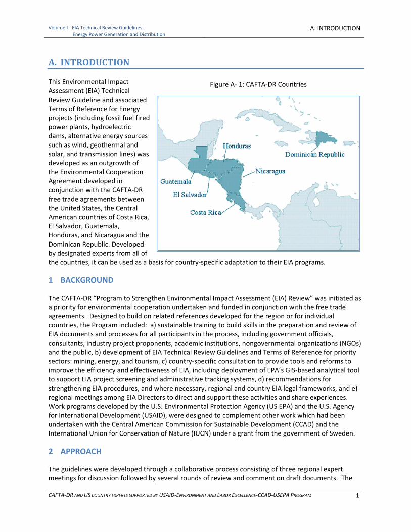
This Environmental Impact Assessment (EIA) Technical Review Guideline and associated Terms of Reference for Energy projects (including fossil fuel fired power plants, hydroelectric dams, alternative energy sources such as wind, geothermal and solar, and transmission lines) was developed as an outgrowth of the Environmental Cooperation Agreement developed in conjunction with the CAFTA‐DR free trade agreements between the United States, the Central American countries of Costa Rica, El Salvador, Guatemala, Honduras, and Nicaragua and the Dominican Republic. Developed by designated experts from all of the countries, it can be used as a basis for country‐specific adaptation to their EIA programs.
1 BACKGROUND
The CAFTA‐DR “Program to Strengthen Environmental Impact Assessment (EIA) Review” was initiated as a priority for environmental cooperation undertaken and funded in conjunction with the free trade agreements. Designed to build on related references developed for the region or for individual countries, the Program included: a) sustainable training to build skills in the preparation and review of EIA documents and processes for all participants in the process, including government officials, consultants, industry project proponents, academic institutions, nongovernmental organizations (NGOs) and the public, b) development of EIA Technical Review Guidelines and Terms of Reference for priority sectors: mining, energy, and tourism, c) country‐specific consultation to provide tools and reforms to improve the efficiency and effectiveness of EIA, including deployment of EPA’s GIS‐based analytical tool to support EIA project screening and administrative tracking systems, d) recommendations for strengthening EIA procedures, and where necessary, regional and country EIA legal frameworks, and e) regional meetings among EIA Directors to direct and support these activities and share experiences. Work programs developed by the U.S. Environmental Protection Agency (US EPA) and the U.S. Agency for International Development (USAID), were designed to complement other work which had been undertaken with the Central American Commission for Sustainable Development (CCAD) and the International Union for Conservation of Nature (IUCN) under a grant from the government of Sweden.
2 APPROACH
The guidelines were developed through a collaborative process consisting of three regional expert meetings for discussion followed by several rounds of review and comment on draft documents. The
Figure A‐ 1: CAFTA‐DR Countries

Volume I ‐ EIA Technical Review Guidelines:
Energy Power Generation and DistributionA. INTRODUCTION
CAFTA‐DR AND US COUNTRY EXPERTS SUPPORTED BY USAID‐ENVIRONMENT AND LABOR EXCELLENCE‐CCAD‐USEPA PROGRAM 2
guidelines also benefitted from the overall guidance and active involvement of country EIA Directors. The work was supported by USAID and their consultants under the Environment and Labor Excellence Program (ELE). The overall approach to the development of Energy Sector EIA Review Guidelines and Terms of Reference was:
a. Creation of an expert team including the designation of senior experts by the Ministers of the Environment and for the Energy Sector from each of the CAFTA‐DR countries and the U.S. (drawn from US EPA’s senior expert EIA Reviewers and sector experts from within EPA, the Department of Energy, and the Federal Energy Regulatory Commission), including the opportunity for CAFTA‐DR country officials also to include the designation of a key academic institution relied upon by the countries for relevant expertise in the energy sector
b. Organization of three regional expert meetings to review and guide all work products drafted with the assistance of a USAID’s Environment and Labor Excellence contractor, Chemonics International
c. Identification of existing resource materials, standards, practices, laws and guidelines related to assessing the environmental impacts from energy projects
d. Development of baseline information on current practice, anticipated growth, existing standards and guidance, norms, permits and environmental measures requirements related to energy production and distribution in the CAFTA‐DR countries and use this to assess the likely impact of adoption of the regional guidelines
e. Development of information on alternatives for pollution control and environmental protection drawn from benchmark organizations, development banks and countries including international practices established by industry, the World Bank, the Inter American Development Bank, the U.S., the European Union and other countries identified by the team of experts as being most relevant
f. Development of options to achieve the benefits of requiring siting, design, construction, operation and closure/reclamation and site reuse approaches which eliminate, reduce, mitigate and/or compensate the adverse direct, indirect and/or cumulative adverse environmental impacts related to energy generation and distribution based on best international practice through a EIA Review guideline and Terms of Reference
g. Adaptation of these guidelines following country‐specific training workshops to be held by CCAD and the individual countries
3 OBJECTIVES OF PRIORITY SECTOR EIA GUIDELINES
Specific objectives of these guidelines included:
a. Improve environmental performance in the sector b. Improve EIA document quality and quality of EIA decision making for the Energy Sector c. Improve efficiency and effectiveness of the EIA process for the energy sector by clarifying
expectations, providing detailed guidelines and aligning preparation and review d. Tailor guidelines to needs of CAFTA‐DR countries e. Provide technical guidelines for the identification of environmental, social and economic
impacts of the energy sector activities f. Identify potential for avoidance and measures for adverse environmental, social and economic
impacts from the energy sector in relation to established requirements of law, industry best practice to empower options for consideration by industry and government officials
Volume I ‐ EIA Technical Review Guidelines:
Energy Power Generation and DistributionA. INTRODUCTION
CAFTA‐DR AND US COUNTRY EXPERTS SUPPORTED BY USAID‐ENVIRONMENT AND LABOR EXCELLENCE‐CCAD‐USEPA PROGRAM 3
g. Encourage public participation throughout the process, a specific priority and request of CAFTA‐DR country officials
4 SCOPE AND CONTENTS OF ENERGY GUIDELINES
The guidelines address:
The full scope of energy generation and transmission activities, including storage and transport of fuels and other raw materials, site selection and development, alternative technologies for generating electricity, distribution through transmission lines, and closure of the facility
Identifying and evaluating the potential environmental impacts, including the physical, biological and social‐economic‐cultural impacts
Evaluating the full range of sustainable environmental measures to prevent, reduce and/or mitigate impacts
The need for enforceable and auditable commitment language in an EIA to ensure that promised actions will be taken by the project proponent and that their adequacy can be determined over time
Model terms of reference for development of renewable energy sources that are cross‐linked to the details provided in the guidelines
The guidelines are organized around each aspect of what is typically required in an EIA document. The guidelines are divided into ten sections with accompanying appendices. These sections are:
A. Introduction B. EIA Process and Public Participation C. Proposed Project Description and Alternatives D. Environmental Setting ( Physical, Biological and Socio‐Economic‐Cultural) E. Potential Impacts F. Assessing Impacts: Predictive Tools and Considerations G. Mitigation and Monitoring Measures H. Environmental Management Plan I. References J. Example Terms of Reference
Guideline appendices are:
A. What is Energy Generation and Transmission B. Overview of Energy Activities in CAFTA‐DR Countries C. Requirements and Standards Applicable to Energy Internationally and Within CAFTA‐DR
Countries, the United States, and Other Countries and International Organizations D. Rules of Thumb for Erosion and Sediment Control E. Sampling and Analysis Plan
Volume I ‐ EIA Technical Review Guidelines:
Energy Power Generation and DistributionA. INTRODUCTION
CAFTA‐DR AND US COUNTRY EXPERTS SUPPORTED BY USAID‐ENVIRONMENT AND LABOR EXCELLENCE‐CCAD‐USEPA PROGRAM 4
5 ACKNOWLEDGEMENTS
The EIA Technical Review Guidelines for the Energy Sector and associated Terms of Reference were developed by experts designated by their Ministers from the environmental and sector agencies of the United States and countries in Central America and the Dominican Republic that are parties to the CAFTA‐DR Free Trade Agreements. Following development of the regional EIA energy documents, the Central American Commission on Environment and Development (CCAD) will host workshops in each of the CAFTA‐DR countries and they will adopt these guidelines for their own use. US EPA‐ USAID/ Program for Environment and Labor Excellence ELE –CCAD CAFTA‐DR Program Team to Strengthen EIA Review
USAID
Rubén Alemán, Contracting Officer Technical Representative, COTR, US AID Regional Program
Orlando Altamirano, CAFTA‐DR Regional Environmental Specialist
Walter Jokisch, Program Coordinator for ELE/Chemonics International, Inc.
Mark Hodges, MACTEC, Inc., Energy Expert Consultant for ELE/Chemonics International, Inc.
Phil Brown, Hydrobro, Expert Consultant for ELE/Chemonics International, Inc.
Lane Krahl, Senior EIA advisor for ELE/Chemonics International, Inc.
Central American Commission for Sustainable Development (CCAD)
Ricardo Aguilar, Chief of Party, Cooperation Agreement USAID ‐ CCAD
Judith Panameño, CCAD, CAFTA‐DR, EPA program coordinator
U.S. Environmental Protection Agency
Orlando González, Coordinator, CAFTA DR, Office of International Activities
Cheryl Wasserman, Manager of the CAFTA DR Program to Strengthen EIA Review, U.S. EPA, Associate Director for Policy Analysis, Office of Federal Activities, Office of Enforcement and Compliance Assurance
María T. Malavé, Technical Liaison for Development of EIA Technical Review Guidelines
Daniel Gala and Brittany Ericksen, Legal Interns Regional Expert Team UNITED STATES Cheryl Wasserman, US EPA Office of Enforcement and Compliance Assurance, Office of Federal Activities María T. Malavé, US EPA Office of Enforcement and Compliance Assurance, Office of Federal Activities Marthea Rountree, Senior NEPA Reviewer, Office of Federal Activities Larry Svoboda, Director of NEPA Program, US EPA Region 8, Denver, Colorado Keith Mason, Senior Analyst, Office of Policy and Review, US EPA Office of Air and Radiation Ann Miles, Director, Hydropower Licensing Division, US Federal Energy Regulatory Commission Eric Cohen, Unit Leader, NEPA Policy and Compliance, US Department of Energy David A. Harris, Forest Service, US Department of Agriculture
Volume I ‐ EIA Technical Review Guidelines:
Energy Power Generation and DistributionA. INTRODUCTION
CAFTA‐DR AND US COUNTRY EXPERTS SUPPORTED BY USAID‐ENVIRONMENT AND LABOR EXCELLENCE‐CCAD‐USEPA PROGRAM 5
COSTA RICA Msc. Sonia Espinosa Valverde, Directora, Secretaria Técnica Nacional Ambiental (SETENA) Vera Quesada Ramírez, Profesional Ambiental, Compañía Nacional de Fuerza y Luz, S.A. Ronald Wright Ceciliano, Profesional, Compañía Nacional de Fuerza y Luz, S.A. Eduardo Murillo Marchena, Coordinador Departamento de Evaluación Ambiental, SETENA DOMINICAN REPUBLIC Lina del Carmen Beriguette Segura, Directora de EIA, Ministerio de Ambiente (MA) Ignacio Leonardo Ramírez, Analista Ambiental, Dirección de Normas Ambientales, MA Víctor Jiménez Vásquez, Analista de Gestión Ambiental, MA Manuel Enrique Peña González, Gerente de Energía, Comisión Nacional de Energía Juan Pablo Banks Peña, Encargado Departamento de Energía y Ambiente, MA El SALVADOR Alberto Fabián, Técnico, MARN Balmore Amaya, Técnico en Evaluación Ambiental, MARN Francisco Rodríguez, Técnico, MARN Carlos José Hidalgo Lemus, Técnico en Evaluación Ambiental, MARN, José Orlando Argueta Lazo, Jefe Unidad Ambiental, CEL GUATEMALA Hirám Pérez, Asesor, MARN Alejandro Recinos Flores, Asesor, MARN Marleny Reyes, Coordinadora de la Unidad de Gestión Socio Ambiental, MEM HONDURAS Manuel Manzanarez, Director, División de Energía NICARAGUA Luis Nicolás Molina Barahona, MARENA Miguel Ángel Matute Hernández, Especialista Ambiental, Ministerio de Energía y Minas Milton Francisco Medina Calero, Ingeniero, Gestión Ambiental, MARENA COUNTRY EIA DIRECTORS Msc. Sonia Espinosa Valverde, SETENA, Costa Rica Lina del Carmen Beriguette Segura, Ministerio de Ambiente, República Dominicana Ing. Hernán Romero, MARN, El Salvador Dra. Eugenia Castro, MARN, Guatemala Julio E. Eguigure, Director de la DECA, SERNA, Honduras Hilda Espinoza, MARENA, Nicaragua

Volume I ‐ EIA Technical Review Guidelines:
Energy Power Generation and DistributionA. INTRODUCTION
CAFTA‐DR AND US COUNTRY EXPERTS SUPPORTED BY USAID‐ENVIRONMENT AND LABOR EXCELLENCE‐CCAD‐USEPA PROGRAM 6
[This page Is intentionally blank.]
Volume I ‐ EIA Technical Review Guidelines:
Energy Power Generation and DistributionB. EIA PROCESS AND PUBLIC PARTICIPATION
CAFTA‐DR AND US COUNTRY EXPERTS SUPPORTED BY USAID‐ENVIRONMENT AND LABOR EXCELLENCE‐CCAD‐USEPA PROGRAM 7
B. EIA PROCESS AND PUBLIC PARTICIPATION
This section describes the general process and practices common to Environmental Impact Assessment (EIA) procedures in CAFTA‐DR countries, along with likely trends future directions of those programs as part of the evolution of the EIA process that has been seen internationally. Because this guideline and Terms of Reference were developed as regional products of designated experts from the CAFTA‐DR countries they can be adapted to the unique features in each country’s EIA laws and procedures.
1 EIA PROCEDURES
No work may begin, that is no site clearing, site preparation or construction, before the Environmental Impact Assessment (EIA) process is complete and government agencies have either approved or provided conditioned approval of a proposed project.
1.1 Project Proponents: From Project Initiation to the EIA Application
A project proponent initiates the idea for a project based on a purpose and need for the action, in this instance there is existing or projected demand for electrical power, which maybe paid for by consumers of the power. Between the idea and the application for EIA to the government for approval, the project proponent will explore project alternatives. It is during this early stage that environmental, social and economic impacts should be introduced, and alternatives developed ‐‐ even before an application is made for EIA. Many problems can be avoided through wise selection of location, site and operations design, and anticipation of issues such the full life cycle of the project, taking the whole of the environmental setting into account early in the process. If environmental consultants or environmental impact expertise are brought in late in the process, at the stage when the proponent needs to prepare an application and an EIA document for approval, it limits the opportunities to build environmental, social and economic considerations into the project proposal as an integral part of developing project feasibility. This is universally considered to be a short sighted practice. Projects which require substantial financing often will have fatal flaw analyses of all sorts performed, including environmental. Some of the outcome of such analyses also feeds the narrative on Project Alternatives and why some of the alternatives were rejected.
1.2 EIA Application, Screening and Categorization
Each CAFTA‐DR country has established its own EIA regulations and guidelines defining different circumstances and procedures for particular types of projects and situations. These regulations distinguish the size and nature of proposed projects or the types of projected impacts for which the full environmental impact assessment procedure and which types of projects or impacts might justify a streamlined procedure based on potential lower level of impact and nature of the proposed activity. Projects usually fall within one of three categories, some of which are further subdivided: A usually is high impact, B1 and B2, medium impact and C low impact but this varies by country. Screening is the process used by government officials to review an application for EIA to determine the appropriate categorization. For the most part, energy production and distribution activities are usually considered among those projects with potentially high or high medium impact.
Volume I ‐ EIA Technical Review Guidelines:
Energy Power Generation and DistributionB. EIA PROCESS AND PUBLIC PARTICIPATION
CAFTA‐DR AND US COUNTRY EXPERTS SUPPORTED BY USAID‐ENVIRONMENT AND LABOR EXCELLENCE‐CCAD‐USEPA PROGRAM 8
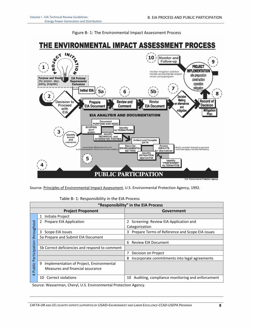
Figure B‐ 1: The Environmental Impact Assessment Process
Source: Principles of Environmental Impact Assessment, U.S. Environmental Protection Agency, 1992.
Table B‐ 1: Responsibility in the EIA Process
“Responsibility” in the EIA Process
Project Proponent Government
4 Public Participation throughout
1 Initiate Project
2 Prepare EIA Application 2 Screening: Review EIA Application and Categorization
3 Scope EIA Issues 3 Prepare Terms of Reference and Scope EIA issues
5a Prepare and Submit EIA Document
6 Review EIA Document
5b Correct deficiencies and respond to comment
7 Decision on Project
8 Incorporate commitments into legal agreements
9 Implementation of Project, Environmental Measures and financial assurance
10 Correct violations 10 Auditing, compliance monitoring and enforcement
Source: Wasserman, Cheryl, U.S. Environmental Protection Agency.

Volume I ‐ EIA Technical Review Guidelines:
Energy Power Generation and DistributionB. EIA PROCESS AND PUBLIC PARTICIPATION
CAFTA‐DR AND US COUNTRY EXPERTS SUPPORTED BY USAID‐ENVIRONMENT AND LABOR EXCELLENCE‐CCAD‐USEPA PROGRAM 9
1.3 Scoping of EIA and Terms of Reference
Scoping is a process used to identify the important issues on which the EIA analysis should focus and those on which it would not be informative to focus. Although any preparer of an EIA would have to engage in a scoping process, the term often is used to describe a process of consultation with interested and affected stakeholders in the project, in the area and infrastructure potentially affected by the project and in the potentially affected resources. In CAFTA‐DR countries of Central America and the Dominican Republic, government officials issue a Terms of Reference to help guide the preparation of an EIA document, in essence a form of scoping which usually includes a requirement for the project proponent to engage the public and stakeholders, including local governments, NGOs and leaders of indigenous groups, before proceeding to prepare the EIA document just for this purpose. In guidelines issued by the International Finance Corporation and as a practice in the U.S. and some CAFTA‐DR countries, the project proponent would carry out public scoping early in the process for the most significant types of projects, presumably to be able to influence the Terms of Reference. Section B2 in this section of the guideline expands on public participation during the scoping process.
1.4 Public Participation throughout the process
EIA is intended to be a transparent process with the opportunity for public involvement from the earliest stages of project development. It is customary for the Terms of Reference to include requirements for the project proponent to engage the public and to document the results of this outreach process in the EIA document. Countries will usually provide a formal opportunity for a public hearing after the EIA document is reviewed by government staff and determined to be complete. The Model Terms of Reference included in this guideline emphasizes the importance of early public involvement to ensure that opportunities for reconciling economic, social and environmental concerns can be considered. A special section on Public Participation is included in this guideline in subsection B2.
1.5 Preparation and Submission of the EIA Document
The structure of EIA documentation of analysis has been fairly standardized over the many years it has been adopted as a practice. It includes:
Executive Summary
Table of Contents
Project Description, Purpose and Need
Alternatives, including the proposed action
Environmental Setting
Assessment of Impacts
Mitigation and Monitoring Measures
Commitment Document: Environmental Management Plan, which contains a facility‐wide monitoring plan and a facility‐wide mitigation plan, which addresses mitigation for environmental and socio‐economic resources
List of preparers
List of Agencies, Organizations, and persons to whom copies of the statement are sent
Index
Appendices

Volume I ‐ EIA Technical Review Guidelines:
Energy Power Generation and DistributionB. EIA PROCESS AND PUBLIC PARTICIPATION
CAFTA‐DR AND US COUNTRY EXPERTS SUPPORTED BY USAID‐ENVIRONMENT AND LABOR EXCELLENCE‐CCAD‐USEPA PROGRAM 10
In countries in Central America and the Dominican Republic, deficiencies in an EIA document are usually addressed through additional supplemental submissions of Annexes and correspondence. If deficiencies are sufficiently significant an EIA document might be rejected and the project proponent would restart the entire process. In the U.S. a draft EIA document is submitted for both government and public review and a final document is then submitted which includes the response to comments and any additional analysis that might be needed.
1.6 EIA Document Review
Government EIA Reviewers have an independent review function to determine if an EIA submitted by a project proponent:
a) Complies with minimum requirements under country laws, regulations, and procedures b) Is complete c) Is accurate d) Is adequate for decision makers to be able to make informed decisions and choices, including
alternatives that might serve to avoid adverse impacts, and reasonable commitments to measures for addressing adverse impacts that cannot be avoided
e) Distinguishes what may be a significant concern from those that are less significant f) Provides a sufficient basis for assuring that commitments to environmental measures will be
met, taking into account not only the EIA but any additional supporting documents such as:
Environmental Management Plan
Mitigation measures that are integrated in the project design, operations and closure, and their maintenance
Monitoring and reporting measures
Infrastructure investments
1.7 Decision on Project
As a decision making process which is informed by the EIA analysis, the actual decision on the project and its rationale is important, particularly if the EIA analysis is not just to be a paper exercise. It therefore is very important that the consideration of alternatives, impacts and their environmental measures be written in a clear and accessible manner to the range of stakeholders who are making decisions related to the project. Part of the decision process is engagement of stakeholders within and outside government in a timely and constructive manner, allowing for the type of give and take needed to address and find acceptable solutions to diverse interests.
1.8 Commitment Language for Environmental Measures
Countries differ on the vehicles they use to establish and hold project proponents accountable for commitments made during the EIA process, ranging from reliance on the EIA document itself, a document from the government establishing project environmental feasibility which highlights commitments, the environmental management plan, a measures plan, an environmental permit, concession and/or contract.
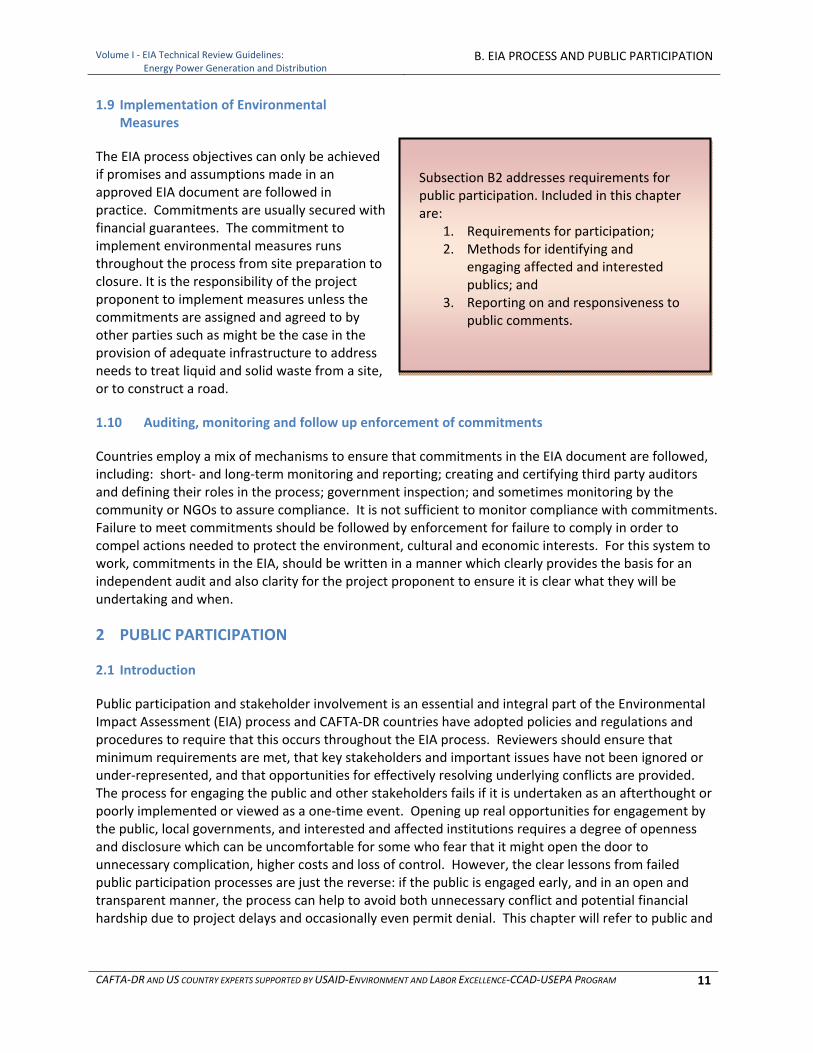
Volume I ‐ EIA Technical Review Guidelines:
Energy Power Generation and DistributionB. EIA PROCESS AND PUBLIC PARTICIPATION
CAFTA‐DR AND US COUNTRY EXPERTS SUPPORTED BY USAID‐ENVIRONMENT AND LABOR EXCELLENCE‐CCAD‐USEPA PROGRAM 11
1.9 Implementation of Environmental Measures
The EIA process objectives can only be achieved if promises and assumptions made in an approved EIA document are followed in practice. Commitments are usually secured with financial guarantees. The commitment to implement environmental measures runs throughout the process from site preparation to closure. It is the responsibility of the project proponent to implement measures unless the commitments are assigned and agreed to by other parties such as might be the case in the provision of adequate infrastructure to address needs to treat liquid and solid waste from a site, or to construct a road.
1.10 Auditing, monitoring and follow up enforcement of commitments
Countries employ a mix of mechanisms to ensure that commitments in the EIA document are followed, including: short‐ and long‐term monitoring and reporting; creating and certifying third party auditors and defining their roles in the process; government inspection; and sometimes monitoring by the community or NGOs to assure compliance. It is not sufficient to monitor compliance with commitments. Failure to meet commitments should be followed by enforcement for failure to comply in order to compel actions needed to protect the environment, cultural and economic interests. For this system to work, commitments in the EIA, should be written in a manner which clearly provides the basis for an independent audit and also clarity for the project proponent to ensure it is clear what they will be undertaking and when.
2 PUBLIC PARTICIPATION
2.1 Introduction
Public participation and stakeholder involvement is an essential and integral part of the Environmental Impact Assessment (EIA) process and CAFTA‐DR countries have adopted policies and regulations and procedures to require that this occurs throughout the EIA process. Reviewers should ensure that minimum requirements are met, that key stakeholders and important issues have not been ignored or under‐represented, and that opportunities for effectively resolving underlying conflicts are provided. The process for engaging the public and other stakeholders fails if it is undertaken as an afterthought or poorly implemented or viewed as a one‐time event. Opening up real opportunities for engagement by the public, local governments, and interested and affected institutions requires a degree of openness and disclosure which can be uncomfortable for some who fear that it might open the door to unnecessary complication, higher costs and loss of control. However, the clear lessons from failed public participation processes are just the reverse: if the public is engaged early, and in an open and transparent manner, the process can help to avoid both unnecessary conflict and potential financial hardship due to project delays and occasionally even permit denial. This chapter will refer to public and
Subsection B2 addresses requirements for public participation. Included in this chapter are:
1. Requirements for participation; 2. Methods for identifying and
engaging affected and interested publics; and
3. Reporting on and responsiveness to public comments.
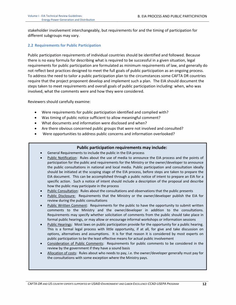
Volume I ‐ EIA Technical Review Guidelines:
Energy Power Generation and DistributionB. EIA PROCESS AND PUBLIC PARTICIPATION
CAFTA‐DR AND US COUNTRY EXPERTS SUPPORTED BY USAID‐ENVIRONMENT AND LABOR EXCELLENCE‐CCAD‐USEPA PROGRAM 12
stakeholder involvement interchangeably, but requirements for and the timing of participation for different subgroups may vary.
2.2 Requirements for Public Participation
Public participation requirements of individual countries should be identified and followed. Because there is no easy formula for describing what is required to be successful in a given situation, legal requirements for public participation are formulated as minimum requirements of law, and generally do not reflect best practices designed to meet the full goals of public participation as an ongoing process. To address the need to tailor a public participation plan to the circumstances some CAFTA DR countries require that the project proponent develop and implement such a plan. The EIA should document the steps taken to meet requirements and overall goals of public participation including: when, who was involved, what the comments were and how they were considered. Reviewers should carefully examine:
Were requirements for public participation identified and complied with?
Was timing of public notice sufficient to allow meaningful comment?
What documents and information were disclosed and when?
Are there obvious concerned public groups that were not involved and consulted?
Were opportunities to address public concerns and information overlooked?
Public participation requirements may include: General Requirements to include the public in the EIA process
Public Notification: Rules about the use of media to announce the EIA process and the points of participation for the public and requirements for the Ministry or the owner/developer to announce the public consultations in national and local media. Public participation and consultation ideally should be initiated at the scoping stage of the EIA process, before steps are taken to prepare the EIA document. This can be accomplished through a public notice of intent to prepare an EIA for a specific action. Such a notice of intent should include a description of the proposal and describe how the public may participate in the process
Public Consultation: Rules about the consultations and observations that the public presents
Public Disclosure: Requirements that the Ministry or the owner/developer publish the EIA for review during the public consultations
Public Written Comment: Requirements for the public to have the opportunity to submit written comments to the Ministry and the owner/developer in addition to the consultations. Requirements may specify whether solicitation of comments from the public should take place in formal public hearings, or may allow or encourage informal workshops or information sessions
Public Hearings: Most laws on public participation provide for the opportunity for a public hearing. This is a formal legal process with little opportunity, if at all, for give and take discussion on options, alternatives and assumptions. It is for that reason it is considered by most experts on public participation to be the least effective means for actual public involvement
Consideration of Public Comments: Requirements for public comments to be considered in the review by the government if they have a sound basis
Allocation of costs: Rules about who needs to pay, i.e. the owner/developer generally must pay for the consultations with some exception where the Ministry pays.
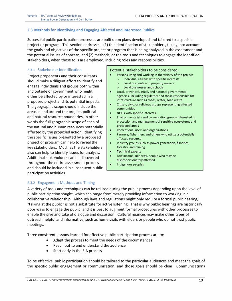
Volume I ‐ EIA Technical Review Guidelines:
Energy Power Generation and DistributionB. EIA PROCESS AND PUBLIC PARTICIPATION
CAFTA‐DR AND US COUNTRY EXPERTS SUPPORTED BY USAID‐ENVIRONMENT AND LABOR EXCELLENCE‐CCAD‐USEPA PROGRAM 13
2.3 Methods for Identifying and Engaging Affected and Interested Publics
Successful public participation processes are built upon plans developed and tailored to a specific project or program. This section addresses: (1) the identification of stakeholders, taking into account the goals and objectives of the specific project or program that is being analyzed in the assessment and the potential issues of concern; and (2) methods, or the tools and techniques to engage the identified stakeholders, when those tolls are employed, including roles and responsibilities.
2.3.1 Stakeholder Identification
Project proponents and their consultants should make a diligent effort to identify and engage individuals and groups both within and outside of government who might either be affected by or interested in a proposed project and its potential impacts. The geographic scope should include the areas in and around the project, political and natural resource boundaries, in other words the full geographic scope of each of the natural and human resources potentially affected by the proposed action. Identifying the specific issues presented by a proposed project or program can help to reveal the key stakeholders. Much as the stakeholders also can help to identify issues for analysis. Additional stakeholders can be discovered throughout the entire assessment process and should be included in subsequent public participation activities.
2.3.2 Engagement Methods and Timing
A variety of tools and techniques can be utilized during the public process depending upon the level of public participation sought, which can range from merely providing information to working in a collaborative relationship. Although laws and regulations might only require a formal public hearing, "talking at the public" is not a substitute for active listening. That is why public hearings are historically poor ways to engage the public, and it is best to augment formal procedures with other processes to enable the give and take of dialogue and discussion. Cultural nuances may make other types of outreach helpful and informative, such as home visits with elders or people who do not trust public meetings. Three consistent lessons learned for effective public participation process are to:
Adapt the process to meet the needs of the circumstances
Reach out to and understand the audience
Start early in the EIA process To be effective, public participation should be tailored to the particular audiences and meet the goals of the specific public engagement or communication, and those goals should be clear. Communications
Potential stakeholders to be considered: Persons living and working in the vicinity of the project
o Individual citizens with specific interests o Local residents and property owners o Local businesses and schools
Local, provincial, tribal, and national governmental agencies, including regulators and those responsible for infrastructure such as roads, water, solid waste
Citizen, civic, or religious groups representing affected communities
NGOs with specific interests
Environmentalists and conservation groups interested in protection and management of sensitive ecosystems and protected areas
Recreational users and organizations
Farmers, fishermen, and others who utilize a potentially affected resource
Industry groups such as power generation, fisheries, forestry, and mining
Technical experts
Low income, minority, people who may be disproportionately affected
Indigenous peoples
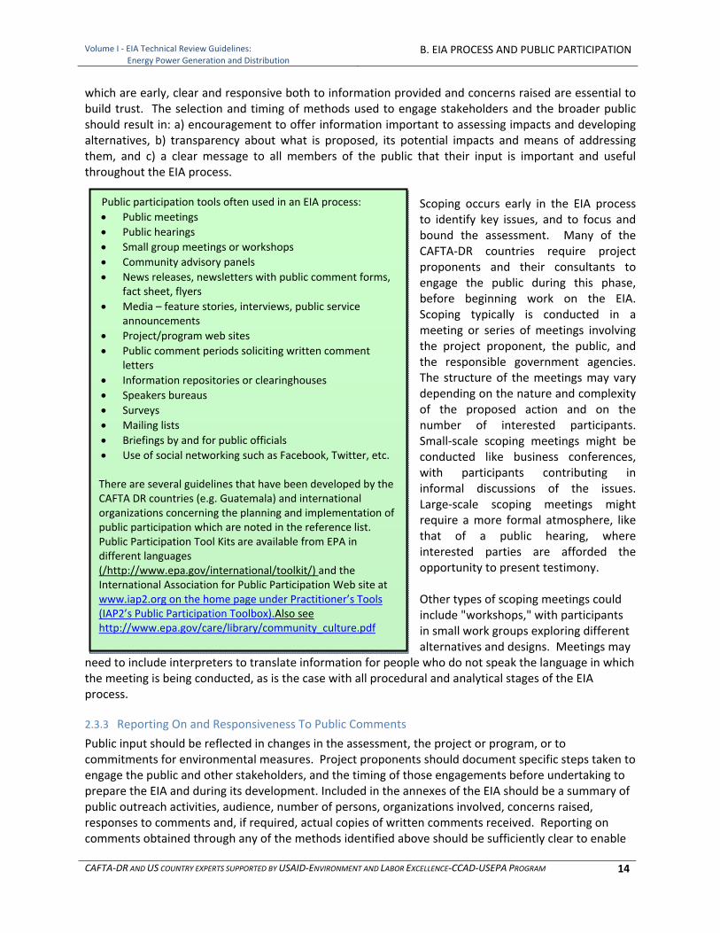
Volume I ‐ EIA Technical Review Guidelines:
Energy Power Generation and DistributionB. EIA PROCESS AND PUBLIC PARTICIPATION
CAFTA‐DR AND US COUNTRY EXPERTS SUPPORTED BY USAID‐ENVIRONMENT AND LABOR EXCELLENCE‐CCAD‐USEPA PROGRAM 14
which are early, clear and responsive both to information provided and concerns raised are essential to build trust. The selection and timing of methods used to engage stakeholders and the broader public should result in: a) encouragement to offer information important to assessing impacts and developing alternatives, b) transparency about what is proposed, its potential impacts and means of addressing them, and c) a clear message to all members of the public that their input is important and useful throughout the EIA process.
Scoping occurs early in the EIA process to identify key issues, and to focus and bound the assessment. Many of the CAFTA‐DR countries require project proponents and their consultants to engage the public during this phase, before beginning work on the EIA. Scoping typically is conducted in a meeting or series of meetings involving the project proponent, the public, and the responsible government agencies. The structure of the meetings may vary depending on the nature and complexity of the proposed action and on the number of interested participants. Small‐scale scoping meetings might be conducted like business conferences, with participants contributing in informal discussions of the issues. Large‐scale scoping meetings might require a more formal atmosphere, like that of a public hearing, where interested parties are afforded the opportunity to present testimony. Other types of scoping meetings could include "workshops," with participants in small work groups exploring different alternatives and designs. Meetings may
need to include interpreters to translate information for people who do not speak the language in which the meeting is being conducted, as is the case with all procedural and analytical stages of the EIA process.
2.3.3 Reporting On and Responsiveness To Public Comments
Public input should be reflected in changes in the assessment, the project or program, or to commitments for environmental measures. Project proponents should document specific steps taken to engage the public and other stakeholders, and the timing of those engagements before undertaking to prepare the EIA and during its development. Included in the annexes of the EIA should be a summary of public outreach activities, audience, number of persons, organizations involved, concerns raised, responses to comments and, if required, actual copies of written comments received. Reporting on comments obtained through any of the methods identified above should be sufficiently clear to enable
Public participation tools often used in an EIA process:
Public meetings
Public hearings
Small group meetings or workshops
Community advisory panels
News releases, newsletters with public comment forms, fact sheet, flyers
Media – feature stories, interviews, public service announcements
Project/program web sites
Public comment periods soliciting written comment letters
Information repositories or clearinghouses
Speakers bureaus
Surveys
Mailing lists
Briefings by and for public officials
Use of social networking such as Facebook, Twitter, etc. There are several guidelines that have been developed by the CAFTA DR countries (e.g. Guatemala) and international organizations concerning the planning and implementation of public participation which are noted in the reference list. Public Participation Tool Kits are available from EPA in different languages (/http://www.epa.gov/international/toolkit/) and the International Association for Public Participation Web site at www.iap2.org on the home page under Practitioner’s Tools (IAP2’s Public Participation Toolbox).Also see http://www.epa.gov/care/library/community_culture.pdf

Volume I ‐ EIA Technical Review Guidelines:
Energy Power Generation and DistributionB. EIA PROCESS AND PUBLIC PARTICIPATION
CAFTA‐DR AND US COUNTRY EXPERTS SUPPORTED BY USAID‐ENVIRONMENT AND LABOR EXCELLENCE‐CCAD‐USEPA PROGRAM 15
an EIA reviewer and the public to assess responsiveness to comments, including whether they were understood, whether they were found to be appropriate or not and why, and if appropriate, what actions were taken to respond to them and whether those actions are sufficient to fully address the concerns. Several approaches might be acceptable to summarize or include actual transcripts and copies of oral and written comments and to demonstrate responsiveness through narrative, tables and cross‐references to specific changes.

Volume I ‐ EIA Technical Review Guidelines:
Energy Power Generation and DistributionB. EIA PROCESS AND PUBLIC PARTICIPATION
CAFTA‐DR AND US COUNTRY EXPERTS SUPPORTED BY USAID‐ENVIRONMENT AND LABOR EXCELLENCE‐CCAD‐USEPA PROGRAM 16
[This page Is intentionally blank.]
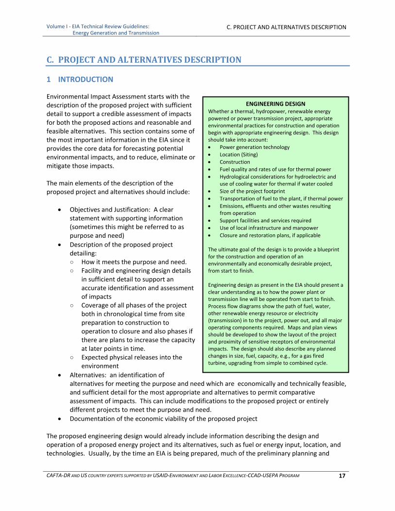
Volume I ‐ EIA Technical Review Guidelines: Energy Generation and Transmission
C. PROJECT AND ALTERNATIVES DESCRIPTION
CAFTA‐DR AND US COUNTRY EXPERTS SUPPORTED BY USAID‐ENVIRONMENT AND LABOR EXCELLENCE‐CCAD‐USEPA PROGRAM 17
ENGINEERING DESIGN Whether a thermal, hydropower, renewable energy powered or power transmission project, appropriate environmental practices for construction and operation begin with appropriate engineering design. This design should take into account:
Power generation technology
Location (Siting)
Construction
Fuel quality and rates of use for thermal power
Hydrological considerations for hydroelectric and use of cooling water for thermal if water cooled
Size of the project footprint
Transportation of fuel to the plant, if thermal power
Emissions, effluents and other wastes resulting from operation
Support facilities and services required
Use of local infrastructure and manpower
Closure and restoration plans, if applicable
The ultimate goal of the design is to provide a blueprint for the construction and operation of an environmentally and economically desirable project, from start to finish. Engineering design as present in the EIA should present a clear understanding as to how the power plant or transmission line will be operated from start to finish. Process flow diagrams show the path of fuel, water, other renewable energy resource or electricity (transmission) in to the project, power out, and all major operating components required. Maps and plan views should be developed to show the layout of the project and proximity of sensitive receptors of environmental impacts. The design should also describe any planned changes in size, fuel, capacity, e.g., for a gas fired turbine, upgrading from simple to combined cycle.
C. PROJECT AND ALTERNATIVES DESCRIPTION
1 INTRODUCTION
Environmental Impact Assessment starts with the description of the proposed project with sufficient detail to support a credible assessment of impacts for both the proposed actions and reasonable and feasible alternatives. This section contains some of the most important information in the EIA since it provides the core data for forecasting potential environmental impacts, and to reduce, eliminate or mitigate those impacts. The main elements of the description of the proposed project and alternatives should include:
Objectives and Justification: A clear statement with supporting information (sometimes this might be referred to as purpose and need)
Description of the proposed project detailing: ○ How it meets the purpose and need. ○ Facility and engineering design details
in sufficient detail to support an accurate identification and assessment of impacts
○ Coverage of all phases of the project both in chronological time from site preparation to construction to operation to closure and also phases if there are plans to increase the capacity at later points in time.
○ Expected physical releases into the environment
Alternatives: an identification of alternatives for meeting the purpose and need which are economically and technically feasible, and sufficient detail for the most appropriate and alternatives to permit comparative assessment of impacts. This can include modifications to the proposed project or entirely different projects to meet the purpose and need.
Documentation of the economic viability of the proposed project The proposed engineering design would already include information describing the design and operation of a proposed energy project and its alternatives, such as fuel or energy input, location, and technologies. Usually, by the time an EIA is being prepared, much of the preliminary planning and
Volume I ‐ EIA Technical Review Guidelines: Energy Generation and Transmission
C. PROJECT AND ALTERNATIVES DESCRIPTION
CAFTA‐DR AND US COUNTRY EXPERTS SUPPORTED BY USAID‐ENVIRONMENT AND LABOR EXCELLENCE‐CCAD‐USEPA PROGRAM 18
engineering design have been completed by the proponent to prove economic feasibility. The designs and construction plans may not be detailed enough for actual construction and implementation, but all aspects of the plan should have been contemplated and preliminary power generation or transmission system designs prepared and compiled. The plan will also contain information on support facilities and labor needs.
2 DOCUMENTATION OF PURPOSE AND NEED
In describing the underlying purpose and need, the EIA should be more specific than assertions that more energy might be needed. The assessment of impacts will be different based on the responses to several questions that need to be made clear in the EIA:
Who needs the energy and for what purpose?
Where is the energy needed and what form should it take?
How much energy is needed and when are different levels needed?
What are the levels of uncertainty in energy need? The purpose and need description also should help to explain whether the proposed project is a new project, an expansion, upgrade or a replacement of an existing project, and whether and why the project might be phased in over time. This information is an important aspect of the project description. It also will help to clarify who the intended recipients are of the energy being generated and/or distributed, i.e. will it be for local use or for users at a distance? Will it be used domestically or exported to other countries?
3 PROJECT AND ALTERNATIVES DESCRIPTION
This section of the EIA should provide information on the proposed project and alternatives sufficient not only to describe how it meets the purpose and need but as a basis for identifying and assessing its impacts. This project description should include, the nature, size and type of project and all related facilities and activities, its design, construction, operation, site design and land area, subsequent anticipated expansion and decommissioning as well as the profile of direct releases into the environment, employment, resource and waste streams, related transportation and the like which are elaborated below for non‐renewable and renewable energy generation and distribution. Additional detail on energy technology is provided in Appendix A. The Project Description section of the EIA should begin with an overview of the proposed activities and a general description of background information to place the proposed energy project in context. Overview information includes project location and access (shown on an overview map), a general description of the overall project including project type, identification of each component including layouts and schematic drawings, waste flowcharts, initial construction sequencing, and life of the operation. Background information includes pre‐construction land uses, land ownership and applicable laws, regulations and best practices. In addition, other alternatives should be identified to the proposed actions. These could include “Do Nothing,” best practices that are not included in the project proposal, an alternative location to avoid or mitigate potential adverse impacts, or other actions as appropriate.

Volume I ‐ EIA Technical Review Guidelines: Energy Generation and Transmission
C. PROJECT AND ALTERNATIVES DESCRIPTION
CAFTA‐DR AND US COUNTRY EXPERTS SUPPORTED BY USAID‐ENVIRONMENT AND LABOR EXCELLENCE‐CCAD‐USEPA PROGRAM 19
3.1 Overall Project Description Information
Typically by the time an EIA is started much of the preliminary design work has been completed by the project proponent to prove economic feasibility and support bankability of the project. The designs and construction plans may not be entirely complete but most if not all of the details required for environmental impact assessment should be available. Project Description: a brief summary of the type (fossil fuel plant, biomass/biofuel plant, hydropower facility, transmission line, etc.) and size (installed capacity and expected energy generation) of the project that is proposed, including a description of all project facilities. It also should include a flow diagram for power generation or transmission showing all components of the plant or transmission system and their relationships to each other. Detailed information required for each type of facility is presented in Subsection 4 Project Alternatives. Project Operations: including a description of how the project will operate (seasonally, monthly, daily, or hourly, as appropriate) and its mode of operation (peaking, base load, run‐of‐the‐river and/or storage). This section should include a roster of all non‐power generating equipment and machinery to be used during project operation, specifying type and quantity by size, weight, motor size, and fuel requirements for each operational activity. Similar information on power generating equipment will be provided below in the Project Alternative Design subsection. This section should also provide the overall energy requirements for operation and source or sources of that energy. Location: the general location of the project and associated activities in terms of:
Political‐administrative location (region, district, town or other relevant political‐administrative units) with accompanying location map.
Means of site access – i.e., by air, river, road, train or vehicle.
Latitude and longitude of project area.
Maps of project area showing location and general plan for the facilities and activities.
Maps of the area of influence that will be included in the EIA analysis, and an explanation of how that area of influence was determined.
Physical Description: a general description of the site and the surrounding area. This is only a summary description as a more detailed description will be presented in the Environmental Settings section of the EIA. This description, however, should summarize information on:
Geology, soils and topography including topographic maps
Vegetative cover
Principal watersheds
Water bodies
Hydrogeology
Roads and landmarks
General land use (specific information is presented in subsection 5.18) Summary of Proposed Project and Alternatives: a general identification and summary of all project alternatives that are reasonable and feasible and meet the purpose and need for the proposed project. In addition to the proposed project, alternatives may include:
Alternative locations
Alternative fuels
Volume I ‐ EIA Technical Review Guidelines: Energy Generation and Transmission
C. PROJECT AND ALTERNATIVES DESCRIPTION
CAFTA‐DR AND US COUNTRY EXPERTS SUPPORTED BY USAID‐ENVIRONMENT AND LABOR EXCELLENCE‐CCAD‐USEPA PROGRAM 20
Alternative site configuration of elements of the project
Alternative size and output capacity
Alternative plans for construction, operation and decommissioning This part of the EIA should also describe the criteria used for identifying which alternatives are fully described and assessed in the EIA. This description should conclude by identifying which alternatives are included in the EIA. Associated Transmission Lines and Connections: including all new and existing lines and connections at the site or connecting the site to existing transmission lines. The information necessary for extensive new transmission lines are described below in Subsection 5 Transmission Lines.
Line voltage
Total length of line in km
Minimum height of conductors over ground level
Width of the right of way in meters
Source
Destination
Number and types of towers
Height of towers
Number of circuits, stations and transformer yards
Points of interconnection between existing and new Construction Phase and Timetable: including the following:
A schedule for each phase of construction for all project and ancillary facilities including, but not limited to: ○ Mobilization ○ Road construction and improvements ○ Land clearing ○ Drilling ○ Blasting ○ Borrow and spoil disposal ○ Erosion and sediment control ○ Excavation and sub grade preparation ○ Foundation preparation ○ Concrete work ○ Construction or installation of each project facility ○ Stabilization of disturbed areas
A GANTT or critical path management chart for the entire project, from start to finish
Equipment ○ Equipment Roster specifying type and quantity by size, weight, motor size, and fuel
requirements for each piece of equipment or machinery used in each activity ○ Transportation mobilization and mobilization frequency ○ Machinery and equipment mobilization routes to be used, as well as the features of the
ways on which they will be transported, including a map of routes, as applicable, and mobilization
Raw materials to be used for construction ○ Give a complete list of the raw materials and construction materials to be used, indicating
the amounts per day, month, and the storage means
Volume I ‐ EIA Technical Review Guidelines: Energy Generation and Transmission
C. PROJECT AND ALTERNATIVES DESCRIPTION
CAFTA‐DR AND US COUNTRY EXPERTS SUPPORTED BY USAID‐ENVIRONMENT AND LABOR EXCELLENCE‐CCAD‐USEPA PROGRAM 21
○ Include an inventory of chemical, toxic or hazardous substances, active elements, sites and storage means, safety aspects regarding transportation and handling and any other relevant information
Construction camp (if applicable) ○ A map at a legible scale appropriate to the size of the project showing all buildings, roads,
transmission and communication lines, drainage systems, etc. ○ Water supply and distribution system including use (m3/day), rights and sources ○ Waste handling and disposal components including sewers, wastewater treatment and solid
waste collection, treatment and disposal facilities ○ Energy generation and use requirements ○ Closure or transition from construction camp to final onsite housing
3.2 Project Scope: Project Phases and Related or Connected Actions
All power generation and distribution projects include the following phases:
Design engineering
Environmental impact assessment (EIA) and permitting
Site Preparation
Construction
Operation and maintenance
Possible up‐gradations or de‐ratings
Decommissioning demobilization All phases and details about them should be provided. All related or connected actions should be addressed in the EIA. There may be different entities and project proponents responsible for different aspects of proposed projects and alternatives. Even if there are different entities involved the test is whether a proposed energy project X would still be proposed if another project Y were not also proposed. For example, an energy generation plant is proposed but the electricity will need to be distributed and connected to transmission lines and the transmission lines would not be proposed for that particular location if it were not for the proposed energy generation plant. So the two projects should be assessed at the same time either by cross referencing in separate EIA documents or within a single, integrated document. The same logic applies to related projects such as pipelines, storage, port facilities and ships delivering fuels and the opening or expansion of quarries for building materials to be used in construction.
4 PROJECT ALTERNATIVES
4.1 Identification and Assessment
Consideration of alternatives is the “heart” of the EIA process and is a requirement of country EIA laws and procedures to foster sustainable development and improved decision making to reconcile economic, environmental and social concerns. This requirement to consider alternatives only pertains to reasonable alternatives, which are those alternatives that meet the underlying purpose for the project and are economically and technically feasible. In many cases analyzing in detail only a subset of alternatives considered would adequately represent the range of reasonable alternatives also In addition, analyzing a No Action alternative is required to provide an environmental baseline for comparison with the proposed action and alternatives. Given the public participation requirements of
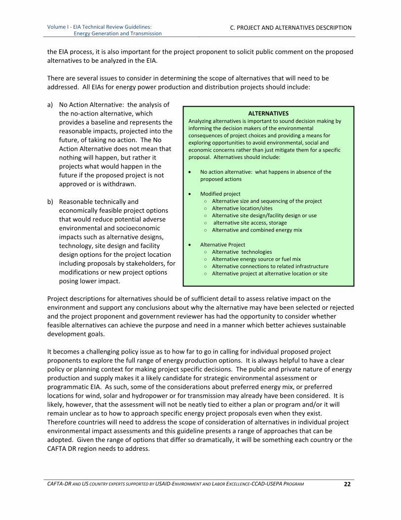
Volume I ‐ EIA Technical Review Guidelines: Energy Generation and Transmission
C. PROJECT AND ALTERNATIVES DESCRIPTION
CAFTA‐DR AND US COUNTRY EXPERTS SUPPORTED BY USAID‐ENVIRONMENT AND LABOR EXCELLENCE‐CCAD‐USEPA PROGRAM 22
ALTERNATIVES Analyzing alternatives is important to sound decision making by informing the decision makers of the environmental consequences of project choices and providing a means for exploring opportunities to avoid environmental, social and economic concerns rather than just mitigate them for a specific proposal. Alternatives should include:
No action alternative: what happens in absence of the proposed actions
Modified project ○ Alternative size and sequencing of the project ○ Alternative location/sites ○ Alternative site design/facility design or use ○ alternative site access, storage ○ Alternative and combined energy mix
Alternative Project ○ Alternative technologies ○ Alternative energy source or fuel mix ○ Alternative connections to related infrastructure ○ Alternative project at alternative location or site
the EIA process, it is also important for the project proponent to solicit public comment on the proposed alternatives to be analyzed in the EIA. There are several issues to consider in determining the scope of alternatives that will need to be addressed. All EIAs for energy power production and distribution projects should include: a) No Action Alternative: the analysis of
the no‐action alternative, which provides a baseline and represents the reasonable impacts, projected into the future, of taking no action. The No Action Alternative does not mean that nothing will happen, but rather it projects what would happen in the future if the proposed project is not approved or is withdrawn.
b) Reasonable technically and
economically feasible project options that would reduce potential adverse environmental and socioeconomic impacts such as alternative designs, technology, site design and facility design options for the project location including proposals by stakeholders, for modifications or new project options posing lower impact.
Project descriptions for alternatives should be of sufficient detail to assess relative impact on the environment and support any conclusions about why the alternative may have been selected or rejected and the project proponent and government reviewer has had the opportunity to consider whether feasible alternatives can achieve the purpose and need in a manner which better achieves sustainable development goals. It becomes a challenging policy issue as to how far to go in calling for individual proposed project proponents to explore the full range of energy production options. It is always helpful to have a clear policy or planning context for making project specific decisions. The public and private nature of energy production and supply makes it a likely candidate for strategic environmental assessment or programmatic EIA. As such, some of the considerations about preferred energy mix, or preferred locations for wind, solar and hydropower or for transmission may already have been considered. It is likely, however, that the assessment will not be neatly tied to either a plan or program and/or it will remain unclear as to how to approach specific energy project proposals even when they exist. Therefore countries will need to address the scope of consideration of alternatives in individual project environmental impact assessments and this guideline presents a range of approaches that can be adopted. Given the range of options that differ so dramatically, it will be something each country or the CAFTA DR region needs to address.
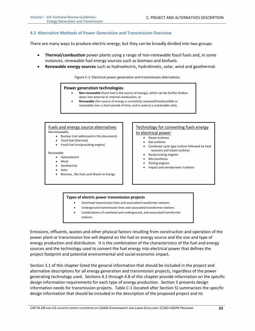
Volume I ‐ EIA Technical Review Guidelines: Energy Generation and Transmission
C. PROJECT AND ALTERNATIVES DESCRIPTION
CAFTA‐DR AND US COUNTRY EXPERTS SUPPORTED BY USAID‐ENVIRONMENT AND LABOR EXCELLENCE‐CCAD‐USEPA PROGRAM 23
4.2 Alternative Methods of Power Generation and Transmission Overview
There are many ways to produce electric energy, but they can be broadly divided into two groups:
Thermal/combustion power plants using a range of non‐renewable fossil fuels and, in some instances, renewable fuel energy sources such as biomass and biofuels.
Renewable energy sources such as hydroelectric, hydrokinetic, solar, wind and geothermal.
Figure C‐1: Electrical power generation and transmission alternatives.
Emissions, effluents, wastes and other physical factors resulting from construction and operation of the power plant or transmission line will depend on the fuel or energy source and the size and type of energy production and distribution. It is the combination of the characteristics of the fuel and energy sources and the technology used to convert the fuel energy into electrical power that defines the project footprint and potential environmental and social‐economic impact. Section 3.1 of this chapter listed the general information that should be included in the project and alternative descriptions for all energy generation and transmission projects, regardless of the power generating technology used. Sections 4.3 through 4.8 of this chapter provide information on the specific design information requirements for each type of energy production. Section 5 presents design information needs for transmission projects. Table C‐1 (located after Section 5) summarizes the specific design information that should be included in the description of the proposed project and its
Fuels and energy source alternatives Nonrenewable
Nuclear (not addressed in this document)
Fossil fuel (thermal)
Fossil fuel (reciprocating engine) Renewable
Hydroelectric
Wind
Geothermal
Solar
Biomass , Bio fuels and Waste to Energy
Technology for converting fuels energy to electrical power
Steam turbines
Gas turbines
Combined cycle (gas turbine followed by heat recovery and steam turbine)
Reciprocating engines
Microturbines
Stirling engines
Impact and aerodynamic turbines
Types of electric power transmission projects
Overhead transmission lines and associated transformer stations
Underground transmission lines and associated transformer stations
Combinations of overhead and underground, and associated transformer
stations
Power generation technologies Non‐renewable (fossil fuel is the source of energy), which can be further broken
down into external or internal combustion, or
Renewable (the source of energy is constantly renewed/inexhaustible or renewable over a short period of time, and is used at a sustainable rate).
Volume I ‐ EIA Technical Review Guidelines: Energy Generation and Transmission
C. PROJECT AND ALTERNATIVES DESCRIPTION
CAFTA‐DR AND US COUNTRY EXPERTS SUPPORTED BY USAID‐ENVIRONMENT AND LABOR EXCELLENCE‐CCAD‐USEPA PROGRAM 24
alternatives, depending on the source of energy. Transmission is also included in Table C‐1. Appendix A presents more detailed information on each of these technologies. Regardless of whether a project is for generation or transmission of electrical power and regardless of the technology used, all project descriptions should include design drawings including plan (overhead) views, elevations (front views) and profiles (side views). The plans should be digitized and presented in a format which is readily readable by the reviewer.
4.3 Thermal/Fossil Fuel Power (Coal, Petroleum or Natural Gas)
Thermal/Fossil Fuel power production uses the combustion of fossil fuels to either directly or indirectly turn generators or alternators that produce electrical energy. The technologies can be divided into two basic categories, external combustion and internal combustion. These two technologies are discussed in the following subsections. The third subsection presents the specific design information that should be included in the Project Description for a thermal/fossil fuel power plant.
4.3.1 External Combustion
External combustion means that combustion of the fuel is external to the machinery that turns the generator or alternator to produce electricity. The heat energy generated by the combustion of fuel is transformed into electrical energy indirectly, usually by means of heating boilers or boiler tubes to generate steam. The resulting steam is then used to power steam turbines or engines that turn generators or alternators, thus creating electrical energy. A steam turbine is a mechanical device that extracts thermal energy from pressurized steam and converts it into rotary motion. It has almost completely replaced the reciprocating piston steam engine because of its greater thermal efficiency and higher power to weight ratio. Because the turbine generates rotary motion, it is particularly suited to be used to drive an electrical generator – about 80 percent of all electricity generation in the world is by use of steam turbines. A typical diagram of a thermal fossil fuel power plant using external combustion is presented Figure C‐2. Although this diagram is for a coal powered plant, the basic components are similar for any thermal power plant using external combustion. The key differences are due to differences in fuel and combustion waste by products, so that 14 through 16 and 18 in the diagram may be different for different types of fuels.
4.3.2 Internal Combustion
Internal combustion means that the fuel is combusted internal to the engine, as in a confined chamber or cylinder and that resulting mechanical action directly turns generators or alternators. Sections 4.3.2.1 through 4.3.2.3 present brief descriptions of the three principal forms of internal combustion engines used to generate electrical energy.
4.3.2.1 Simple Cycle Combustion Turbine
Simple cycle combustion turbine (SCCT) is a type of gas or oil fired turbine most frequently used in the power industry. The main advantage of an SCCT is the ability for it to "cycle" or be turned on and off within minutes. Due to their ability to operate from several hours per day to dozens of hours per year, SCCTs are useful for supplying power during peak demand. In areas with a shortage of base load a gas turbine power plant may regularly operate during most hours of the day and even into the evening. A
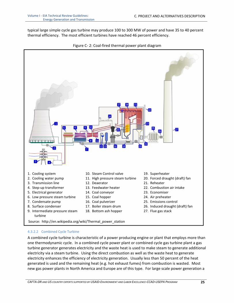
Volume I ‐ EIA Technical Review Guidelines: Energy Generation and Transmission
C. PROJECT AND ALTERNATIVES DESCRIPTION
CAFTA‐DR AND US COUNTRY EXPERTS SUPPORTED BY USAID‐ENVIRONMENT AND LABOR EXCELLENCE‐CCAD‐USEPA PROGRAM 25
typical large simple cycle gas turbine may produce 100 to 300 MW of power and have 35 to 40 percent thermal efficiency. The most efficient turbines have reached 46 percent efficiency.
Figure C‐ 2: Coal‐fired thermal power plant diagram
1. Cooling system 2. Cooling water pump 3. Transmission line 4. Step‐up transformer 5. Electrical generator 6. Low pressure steam turbine 7. Condensate pump 8. Surface condenser 9. Intermediate pressure steam
turbine
10. Steam Control valve11. High pressure steam turbine 12. Deaerator 13. Feedwater heater 14. Coal conveyor 15. Coal hopper 16. Coal pulverizer 17. Boiler steam drum 18. Bottom ash hopper
19. Superheater 20. Forced draught (draft) fan 21. Reheater 22. Combustion air intake 23. Economiser 24. Air preheater 25. Emissions control 26. Induced draught (draft) fan
27. Flue gas stack
Source: http://en.wikipedia.org/wiki/Thermal_power_station
4.3.2.2 Combined Cycle Turbine
A combined cycle turbine is characteristic of a power producing engine or plant that employs more than one thermodynamic cycle. In a combined cycle power plant or combined cycle gas turbine plant a gas turbine generator generates electricity and the waste heat is used to make steam to generate additional electricity via a steam turbine. Using the direct combustion as well as the waste heat to generate electricity enhances the efficiency of electricity generation. Usually less than 50 percent of the heat generated is used and the remaining heat (e.g. hot exhaust fumes) from combustion is wasted. Most new gas power plants in North America and Europe are of this type. For large scale power generation a

Volume I ‐ EIA Technical Review Guidelines: Energy Generation and Transmission
C. PROJECT AND ALTERNATIVES DESCRIPTION
CAFTA‐DR AND US COUNTRY EXPERTS SUPPORTED BY USAID‐ENVIRONMENT AND LABOR EXCELLENCE‐CCAD‐USEPA PROGRAM 26
typical set would be a 400 megawatt (MW) Gas Turbine coupled to a 200 MW Steam Turbine giving 600 MW. A typical power station might comprise of between 2 and 6 such sets.
4.3.2.3 Reciprocating Engine Generators
Only large capacity diesel reciprocating engine generators are considered in these guidelines as gasoline powered systems are generally not used in the energy sector. A reciprocating engine generator is a combination of a diesel engine, a generator and various ancillary devices such as base, canopy, sound attenuation, control systems, circuit breakers, jacket water heaters, starting systems etc. Sizes up to about five MW are used for small power stations, which may use up to 20 units. In these larger sizes the engine and generator are brought to site separately and assembled along with ancillary equipment. Diesel generators, sometimes as small as 250 kilovolt amps, are widely used at power plants not only for emergency power, but also many have a secondary function of feeding power to utility grids either during peak periods, or periods when there is a shortage of large power generators. One or more diesel generators operating without a connection to an electrical grid are said to be operating in "island" mode. Several parallel generators provide the advantages of redundancy and better efficiency at partial loads. An island power plant intended for primary power source of an isolated community will often have at least three diesel generators, any two of which are rated to carry the required load. Groups of up to 20 are not uncommon.
4.3.3 Implications for Project Description
In addition to the list of general information presented in Section 3.1, thermal/fossil fuel project descriptions should include design information and specifications for the following:
Type of technology (external combustion with steam turbine, or internal combustion with combined cycle turbine, simple cycle combustion turbine, or reciprocating engine)
Design details for each power generation component (as appropriate) ○ Combustion chambers ○ Boilers ○ Steam controls ○ Turbines ○ Generators ○ Cooling systems ○ Noise control ○ Fuel storage ○ Amount, type and constituents of the waste from fuel combustion ○ Plans for storage and disposal of combustion waste ○ Heat and extent of thermal discharge as well as heat discharge control technology ○ Treatment and emission of exhaust gases Use of air pollution control devices (electrostatic precipitators, baghouses, cyclones,
scrubbers, dust suppressants, steam injection, limestone or ammonia injection, fuel cleaning and or use of cleaner fuels, and other control measures)
Disposal of dust and slag from treatment systems Optimization of stoichiometry of combustion Limitation of process rates or hours of operation Design of stacks to minimize downwash or near field plume impacts
Type of fuel or mix, indicating:
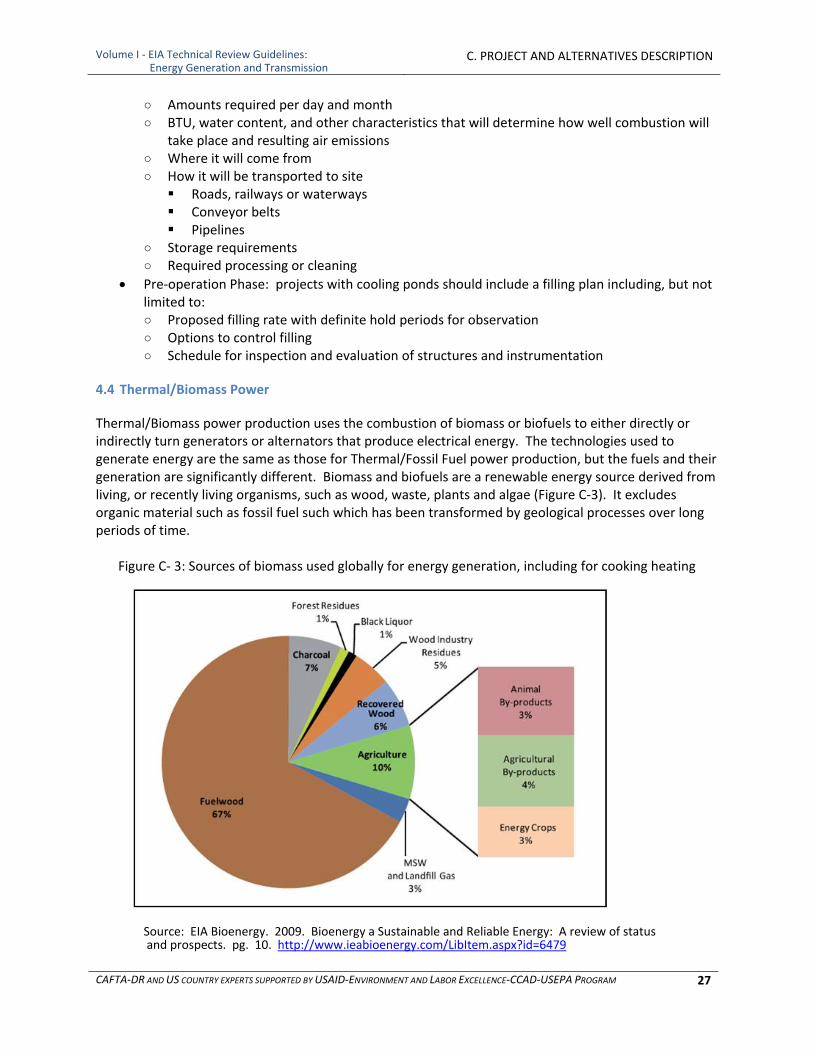
Volume I ‐ EIA Technical Review Guidelines: Energy Generation and Transmission
C. PROJECT AND ALTERNATIVES DESCRIPTION
CAFTA‐DR AND US COUNTRY EXPERTS SUPPORTED BY USAID‐ENVIRONMENT AND LABOR EXCELLENCE‐CCAD‐USEPA PROGRAM 27
○ Amounts required per day and month ○ BTU, water content, and other characteristics that will determine how well combustion will
take place and resulting air emissions ○ Where it will come from ○ How it will be transported to site Roads, railways or waterways Conveyor belts Pipelines
○ Storage requirements ○ Required processing or cleaning
Pre‐operation Phase: projects with cooling ponds should include a filling plan including, but not limited to: ○ Proposed filling rate with definite hold periods for observation ○ Options to control filling ○ Schedule for inspection and evaluation of structures and instrumentation
4.4 Thermal/Biomass Power
Thermal/Biomass power production uses the combustion of biomass or biofuels to either directly or indirectly turn generators or alternators that produce electrical energy. The technologies used to generate energy are the same as those for Thermal/Fossil Fuel power production, but the fuels and their generation are significantly different. Biomass and biofuels are a renewable energy source derived from living, or recently living organisms, such as wood, waste, plants and algae (Figure C‐3). It excludes organic material such as fossil fuel such which has been transformed by geological processes over long periods of time.
Figure C‐ 3: Sources of biomass used globally for energy generation, including for cooking heating
Source: EIA Bioenergy. 2009. Bioenergy a Sustainable and Reliable Energy: A review of status and prospects. pg. 10. http://www.ieabioenergy.com/LibItem.aspx?id=6479

Volume I ‐ EIA Technical Review Guidelines: Energy Generation and Transmission
C. PROJECT AND ALTERNATIVES DESCRIPTION
CAFTA‐DR AND US COUNTRY EXPERTS SUPPORTED BY USAID‐ENVIRONMENT AND LABOR EXCELLENCE‐CCAD‐USEPA PROGRAM 28
Thermal/Biomass power production includes the external combustion of biomass such as wood, hemp, miscanthus, crop by‐products (straw, field residues, rice husks, corn cobs, etc.), solid waste or biofuels to heat boilers or boiler tubes to generate steam. The steam is then used to turn generators or alternators. It also includes the use of biofuels to directly fuel internal combustion turbines or reciprocating engines hooked to turbines. The system components are the same as those presented in Figure C‐2 with the exception of the fuel preparation and delivery (items 14‐16). Biofuels are derived from conversion of biomass (organic material) into a combustible fuel. Biomass can be converted into biofuels via physical extraction (as in the case of some oils), decomposition, fermentation, thermal processes, or chemical processes. Biofuels may be gases such as methane or liquids such as ethanol or biodiesel. Most biofuel production comes from harvesting organic matter and then converting it to fuel but an alternative approach relies on the fact that some algae naturally produce ethanol and this can be collected without killing the algae. In addition to being used to power external combustion systems, biofuels can be used to power internal combustion, so that they can be used as fuel for the technologies described in subsection 4.3.2. Several agricultural products are specifically grown for biofuel production:
Corn, switchgrass and soybeans, primarily in the United States
Rapeseed wheat and sugar beet primarily in Europe
Sugarcane in Brazil
Palm oil and miscanthus in South‐East Asia
Sorghum and cassava in China
Jatropha and Pongamia pinnata in India
Pongamia pinnata in Australia and the tropics
Hemp has also been proven to work as a biofuel In addition to the general list above in 3.1 and the specific design information required for thermal plants in 4.3, biomass project descriptions should include:
Source of biomass (specific locations of production centers, including solid waste facilities if applicable)
Land dedicated to growing/producing crops or trees for biomass ○ Development of support facilities, such as irrigation systems including diversions, reservoirs,
canals, etc. ○ Chemical use and storage for pesticides and fertilizers on production lands
Design details for any treatment for biomass use or conversion for biofuel required before use ○ Energy demands and sources for treatment ○ Releases to the environment
Storage of raw and treated materials
4.5 Hydropower
Hydropower is further subdivided into the categories of hydroelectric power and hydrokinetic power. Hydroelectric projects generate electricity from the flow of water with use of a dam or diversion, whereas hydrokinetic projects generate electricity from the movement of waves or currents without the use of a dam or diversion.

Volume I ‐ EIA Technical Review Guidelines: Energy Generation and Transmission
C. PROJECT AND ALTERNATIVES DESCRIPTION
CAFTA‐DR AND US COUNTRY EXPERTS SUPPORTED BY USAID‐ENVIRONMENT AND LABOR EXCELLENCE‐CCAD‐USEPA PROGRAM 29
4.5.1 Hydroelectric Power
Hydroelectric power is categorized by capacity as being pico (< 5 kW), micro (< 100 kW), mini (< 1 MW), small (< 30 MW) and large (> 30 MW), and by head, where low head is < 30 meters, medium is 30‐300 meters and high head is > 300 meters. Most hydroelectric projects connected to the grid in CAFTA‐DR countries are large, however there is growing interest in smaller projects (pico, micro, mini or small capacity) because they can serve small remote communities or individual facilities. If these facilities are not located near endangered species and do not significantly alter the flow of the river, they can offer a relatively benign source of energy. There are three types of hydroelectric power projects: conventional, pumped storage and instream energy generation technology.
a) Conventional projects, use a dam or diversion, and may operate in a run‐of‐the‐river mode, where outflow from the project approximates inflow, or peaking, where flows are stored and released on a daily, monthly, or seasonal basis. To increase “head” for electrical generation, the developer may construct the powerhouse downstream from the dam, diverting water from a section of river known as the bypassed reach. Figures C‐4 and C‐5 present diagrams of typical conventional hydroelectric projects.
b) Pumped storage projects use bodies of water at two different elevations. Water flows to the lower body of water by gravity, generating power during periods of peak electrical use and pumping water back uphill during off‐peak hours (see Figure C‐6). If both the upper and lower bodies of water are distinct reservoirs, the pumped storage is considered closed. Conversely, an open pumped storage system would typically have a dammed river as either the upper or lower water body.
c) Instream energy generation technology derives power from low‐head turbines placed directly in rivers or manmade channels, where the current directly turns the turbine generating electrical energy. These systems require no dams or diversions, so that their environmental impacts can be relatively benign. Low‐head turbines turn much slower than conventional turbines and generate less energy per turbine (10 to 40 kW per turbine) requiring many more to be built for a given level of energy production.
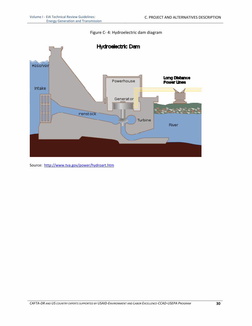
Volume I ‐ EIA Technical Review Guidelines: Energy Generation and Transmission
C. PROJECT AND ALTERNATIVES DESCRIPTION
CAFTA‐DR AND US COUNTRY EXPERTS SUPPORTED BY USAID‐ENVIRONMENT AND LABOR EXCELLENCE‐CCAD‐USEPA PROGRAM 30
Figure C‐ 4: Hydroelectric dam diagram
Source: http://www.tva.gov/power/hydroart.htm
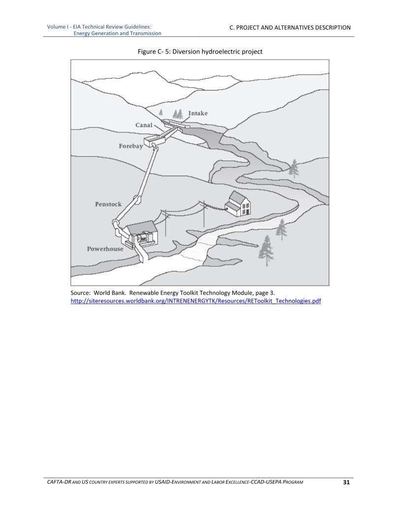
Volume I ‐ EIA Technical Review Guidelines: Energy Generation and Transmission
C. PROJECT AND ALTERNATIVES DESCRIPTION
CAFTA‐DR AND US COUNTRY EXPERTS SUPPORTED BY USAID‐ENVIRONMENT AND LABOR EXCELLENCE‐CCAD‐USEPA PROGRAM 31
Figure C‐ 5: Diversion hydroelectric project
Source: World Bank. Renewable Energy Toolkit Technology Module, page 3. http://siteresources.worldbank.org/INTRENENERGYTK/Resources/REToolkit_Technologies.pdf
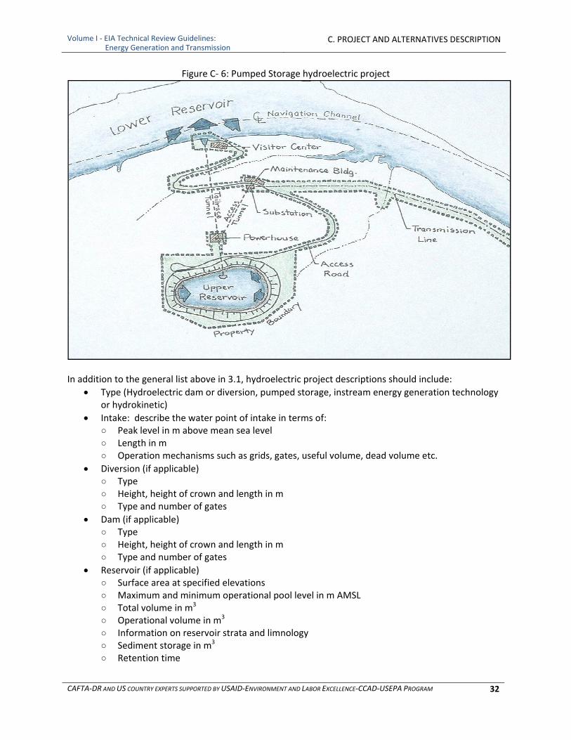
Volume I ‐ EIA Technical Review Guidelines: Energy Generation and Transmission
C. PROJECT AND ALTERNATIVES DESCRIPTION
CAFTA‐DR AND US COUNTRY EXPERTS SUPPORTED BY USAID‐ENVIRONMENT AND LABOR EXCELLENCE‐CCAD‐USEPA PROGRAM 32
Figure C‐ 6: Pumped Storage hydroelectric project
In addition to the general list above in 3.1, hydroelectric project descriptions should include:
Type (Hydroelectric dam or diversion, pumped storage, instream energy generation technology or hydrokinetic)
Intake: describe the water point of intake in terms of: ○ Peak level in m above mean sea level ○ Length in m ○ Operation mechanisms such as grids, gates, useful volume, dead volume etc.
Diversion (if applicable) ○ Type ○ Height, height of crown and length in m ○ Type and number of gates
Dam (if applicable) ○ Type ○ Height, height of crown and length in m ○ Type and number of gates
Reservoir (if applicable) ○ Surface area at specified elevations ○ Maximum and minimum operational pool level in m AMSL ○ Total volume in m3 ○ Operational volume in m3 ○ Information on reservoir strata and limnology ○ Sediment storage in m3 ○ Retention time

Volume I ‐ EIA Technical Review Guidelines: Energy Generation and Transmission
C. PROJECT AND ALTERNATIVES DESCRIPTION
CAFTA‐DR AND US COUNTRY EXPERTS SUPPORTED BY USAID‐ENVIRONMENT AND LABOR EXCELLENCE‐CCAD‐USEPA PROGRAM 33
○ Height‐volume curve ○ Lining (if applicable)
Power house ○ Number and type of turbines ○ Minimum and maximum hydraulic capacity of turbines ○ Cooling system ○ Generators ○ Other special equipment
Tunnels and canals ○ Lengths in km ○ Cross sections indicating size in m and construction materials
Penstocks and pipelines ○ Lengths in km ○ Cross sections indicating size in m and construction materials
Pre‐operation Phase: Reservoir filling plan (if appropriate) including, but not limited to: ○ Proposed filling rate with definite hold periods for observation ○ Options to control filling ○ Schedule for inspection and evaluation of structures and instrumentation
4.5.2 Hydrokinetic Power
Hydrokinetic power is defined as projects that generate electricity from waves or directly from the flow of water in ocean currents, tides or inland waterways without use of a dam. Hydrokinetic power is a newer development and it is estimated that 30% or more of global power needs in nations having enough coastal access could be generated using hydrokinetic power. There are four types of wave energy devices: point absorbers, attenuators, overtopping terminators, and oscillating water column terminators (see Figure C‐7). Current energy devices consist of a rotor and generator. The two types are axial, which are typically horizontal (Figure C‐8) and cross flow (either vertical or horizontal). Point absorbers are floating structures with one component (generally a buoy) that moves up and down with wave action and another component that is fixed to the ocean floor or relatively fixed via a submerged damper. The two components move independently, causing a piston action, which is converted to energy via electromechanical or hydraulic converters. Point absorbers are not currently being used anywhere as a major energy source, but experimental versions have proven that they produce energy. Attenuators are long, multi‐segment floating structures oriented parallel to the direction of wave travel. The motion of the waves moves the segments independently, causing them to flex at the joints where the segments connect. The flexing action is converted into energy via hydraulic pumps or other converters. Those connected to hydraulic pumps pressurize hydraulic fluid, which is then used to drive a generator. The first commercial wave farm using Pelamis attenuators began operation in 2008 off the coast of Portugal (Aguçadoura). But since has shut down; first for technical reasons, then for later for financial reasons. Overtopping terminators float at or near the ocean surface, perpendicular to the direction of wave travel and located near the shore where waves break. They have reservoirs that are filled when waves

Volume I ‐ EIA Technical Review Guidelines: Energy Generation and Transmission
C. PROJECT AND ALTERNATIVES DESCRIPTION
CAFTA‐DR AND US COUNTRY EXPERTS SUPPORTED BY USAID‐ENVIRONMENT AND LABOR EXCELLENCE‐CCAD‐USEPA PROGRAM 34
overtop the structure. After the device is overtopped, the water in the reservoir is above the average surrounding sea level. The water is then released through a controlled opening in the reservoir, and gravity causes it to fall back toward the ocean surface. The energy of the falling water is used to turn conventional, low‐head hydro turbines. No overtopping terminators are currently proposed for use in the United States; however, projects and prototypes have been demonstrated in the United Kingdom, Denmark and Portugal. Oscillating water column (OWC) terminators are built on shore, perpendicular to the direction of wave travel. When waves break on shore, water enters through a subsurface opening into a chamber with air trapped above it. The wave action causes the captured water column to move up and down like a piston, forcing the air though an opening connected to a wind turbine. A full‐scale, 500‐kW, prototype OWC designed and built by Energetech is undergoing testing offshore at Port Kembla in Australia. The technology has also been demonstrated in the United Kingdom and Portugal, and at least two projects are under development in the United States. In addition to the general list above in 3.1, hydrokinetic project descriptions should include:
Description, including dimensions, of all devices, moorings, safety markers, and transmission line to shore facilities
All land‐based facilities and technologies used to capture and distribute the electricity
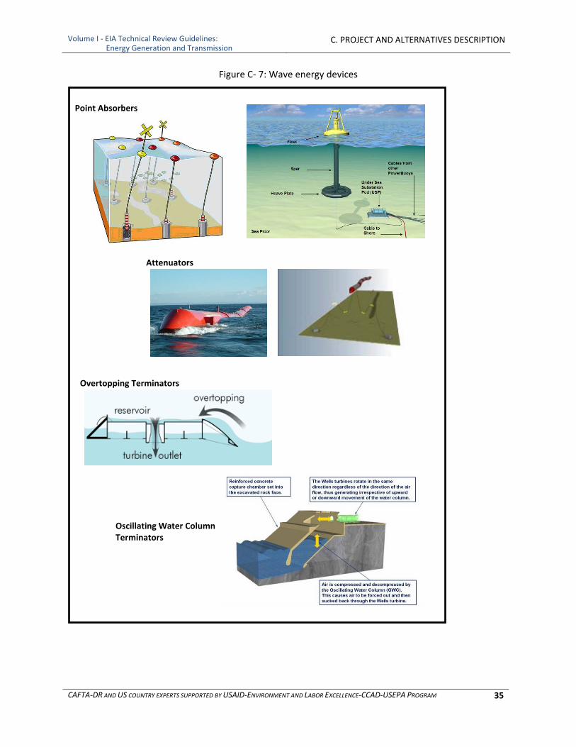
Volume I ‐ EIA Technical Review Guidelines: Energy Generation and Transmission
C. PROJECT AND ALTERNATIVES DESCRIPTION
CAFTA‐DR AND US COUNTRY EXPERTS SUPPORTED BY USAID‐ENVIRONMENT AND LABOR EXCELLENCE‐CCAD‐USEPA PROGRAM 35
Point Absorbers
Overtopping Terminators
Attenuators
Oscillating Water Column Terminators
Figure C‐ 7: Wave energy devices
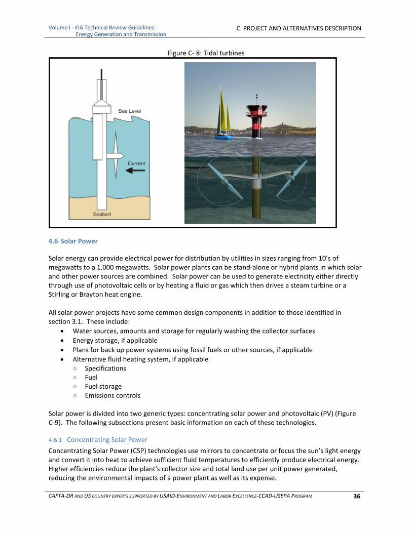
Volume I ‐ EIA Technical Review Guidelines: Energy Generation and Transmission
C. PROJECT AND ALTERNATIVES DESCRIPTION
CAFTA‐DR AND US COUNTRY EXPERTS SUPPORTED BY USAID‐ENVIRONMENT AND LABOR EXCELLENCE‐CCAD‐USEPA PROGRAM 36
Figure C‐ 8: Tidal turbines
4.6 Solar Power
Solar energy can provide electrical power for distribution by utilities in sizes ranging from 10’s of megawatts to a 1,000 megawatts. Solar power plants can be stand‐alone or hybrid plants in which solar and other power sources are combined. Solar power can be used to generate electricity either directly through use of photovoltaic cells or by heating a fluid or gas which then drives a steam turbine or a Stirling or Brayton heat engine. All solar power projects have some common design components in addition to those identified in section 3.1. These include:
Water sources, amounts and storage for regularly washing the collector surfaces
Energy storage, if applicable
Plans for back up power systems using fossil fuels or other sources, if applicable
Alternative fluid heating system, if applicable ○ Specifications ○ Fuel ○ Fuel storage ○ Emissions controls
Solar power is divided into two generic types: concentrating solar power and photovoltaic (PV) (Figure C‐9). The following subsections present basic information on each of these technologies.
4.6.1 Concentrating Solar Power
Concentrating Solar Power (CSP) technologies use mirrors to concentrate or focus the sun’s light energy and convert it into heat to achieve sufficient fluid temperatures to efficiently produce electrical energy. Higher efficiencies reduce the plant's collector size and total land use per unit power generated, reducing the environmental impacts of a power plant as well as its expense.

Volume I ‐ EIA Technical Review Guidelines: Energy Generation and Transmission
C. PROJECT AND ALTERNATIVES DESCRIPTION
CAFTA‐DR AND US COUNTRY EXPERTS SUPPORTED BY USAID‐ENVIRONMENT AND LABOR EXCELLENCE‐CCAD‐USEPA PROGRAM 37
There are four primary types of CSP plants:
parabolic troughs
linear Fresnel systems
power towers
parabolic dishes With a parabolic trough system the sun’s energy is concentrated using parabolically curved, trough‐shaped reflectors (Figure C‐10) onto a receiver pipe running along the focal line of the curved surface in which there is a heat transfer fluid. A Fresnel system is similar to a trough in that mirrors focus the sun’s energy onto a pipe in which there is a heat transfer fluid. The mirrors, however, are in long narrow strips located close to the ground. Power towers utilize an array of sun‐tracking mirrors (heliostats) to focus sunlight on a receiver at the top of a tower in the center of the array, which contains a heat transfer fluid. In all three systems the hot heat transfer fluid is used to generate steam to power a turbine, similar to that used in other thermal power plants. As such, a solar thermal plant can have most of components 1‐13 in Figure C‐2, as can be seen in the system diagrams presented in Figures C‐11 and C‐12. Parabolic trough, linear Fresnel and power tower plants generate heat to convert water to steam, but many plants also store excess heat for subsequent use. With current technology, storage of heat is much cheaper and more efficient than storage of electricity. This can be seen in the “Thermal Storage” component in Figure C‐11. This design runs a heat transfer fluid through the parabolic array and to a heat exchanger for the water/steam system, turning the water into steam that then drives a steam turbine. When the sun is strong enough to provide more energy than is needed for the direct heat exchange, a portion of the heated transfer fluid passes through an exchanger for the liquid salt system, which heats liquid salt from the cold tank and stores it in the hot tank. When the solar energy is insufficient to provide the necessary energy to transform water into steam, the hot liquid salt can be pumped through the heat exchanger, thus boosting the temperature of the transfer fluid. When the sun goes down, the storage system can continue to heat the fluid. In this way, the CSP plant can produce electricity day and night. Some projects install a back‐up system that uses fossil energy to fire boilers.
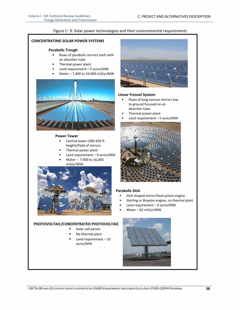
Volume I ‐ EIA Technical Review Guidelines: Energy Generation and Transmission
C. PROJECT AND ALTERNATIVES DESCRIPTION
CAFTA‐DR AND US COUNTRY EXPERTS SUPPORTED BY USAID‐ENVIRONMENT AND LABOR EXCELLENCE‐CCAD‐USEPA PROGRAM 38
CONCENTRATING SOLAR POWER SYSTEMS
Parabolic Trough • Rows of parabolic mirrors each with
an absorber tube
• Thermal power plant
• Land requirement – 5 acres/MW
• Water – 7,400 to 16,000 m3/yr/MW
Linear Fresnel System• Rows of long narrow mirrors low
to ground focused on an absorber tube
• Thermal power plant
• Land requirement – 5 acres/MW
• Water – 7,400 to 16,000 m3/yr/MW
Power Tower • Central tower (300‐450 ft
height)/field of mirrors
• Thermal power plant
• Land requirement – 9 acres/MW
• Water – 7,400 to 16,000 m3/yr/MW
Parabolic Dish• Dish shaped mirror/heat piston engine
• Sterling or Brayton engine, no thermal plant
• Land requirement – 9 acres/MW
• Water – 62 m3/yr/MW
PHOTOVOLTAIC/CONCENTRATED PHOTOVOLTAIC• Solar cell panels
• No thermal plant
• Land requirement – 10 acres/MW
/ /
Figure C‐ 9: Solar power technologies and their environmental requirements
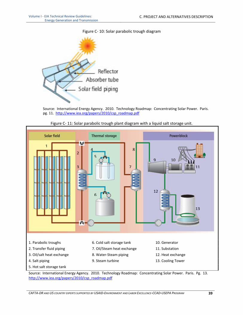
Volume I ‐ EIA Technical Review Guidelines: Energy Generation and Transmission
C. PROJECT AND ALTERNATIVES DESCRIPTION
CAFTA‐DR AND US COUNTRY EXPERTS SUPPORTED BY USAID‐ENVIRONMENT AND LABOR EXCELLENCE‐CCAD‐USEPA PROGRAM 39
Figure C‐ 10: Solar parabolic trough diagram
Source: International Energy Agency. 2010. Technology Roadmap: Concentrating Solar Power. Paris. pg. 11. http://www.iea.org/papers/2010/csp_roadmap.pdf
Figure C‐ 11: Solar parabolic trough plant diagram with a liquid salt storage unit.
1. Parabolic troughs 6. Cold salt storage tank 10. Generator
2. Transfer fluid piping 7. Oil/Steam heat exchange 11. Substation
3. Oil/salt heat exchange 8. Water‐Steam piping 12. Heat exchange
4. Salt piping 9. Steam turbine 13. Cooling Tower
5. Hot salt storage tank
Source: International Energy Agency. 2010. Technology Roadmap: Concentrating Solar Power. Paris. Pg. 13. http://www.iea.org/papers/2010/csp_roadmap.pdf
1
3
5
6
7
12
9
11
13
24 8
10
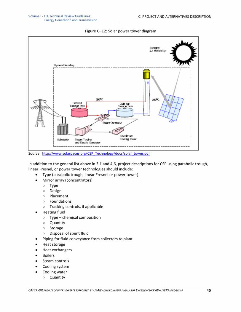
Volume I ‐ EIA Technical Review Guidelines: Energy Generation and Transmission
C. PROJECT AND ALTERNATIVES DESCRIPTION
CAFTA‐DR AND US COUNTRY EXPERTS SUPPORTED BY USAID‐ENVIRONMENT AND LABOR EXCELLENCE‐CCAD‐USEPA PROGRAM 40
Figure C‐ 12: Solar power tower diagram
Source: http://www.solarpaces.org/CSP_Technology/docs/solar_tower.pdf
In addition to the general list above in 3.1 and 4.6, project descriptions for CSP using parabolic trough, linear Fresnel, or power tower technologies should include:
Type (parabolic trough, linear Fresnel or power tower)
Mirror array (concentrators) ○ Type ○ Design ○ Placement ○ Foundations ○ Tracking controls, if applicable
Heating fluid ○ Type – chemical composition ○ Quantity ○ Storage ○ Disposal of spent fluid
Piping for fluid conveyance from collectors to plant
Heat storage
Heat exchangers
Boilers
Steam controls
Cooling system
Cooling water ○ Quantity
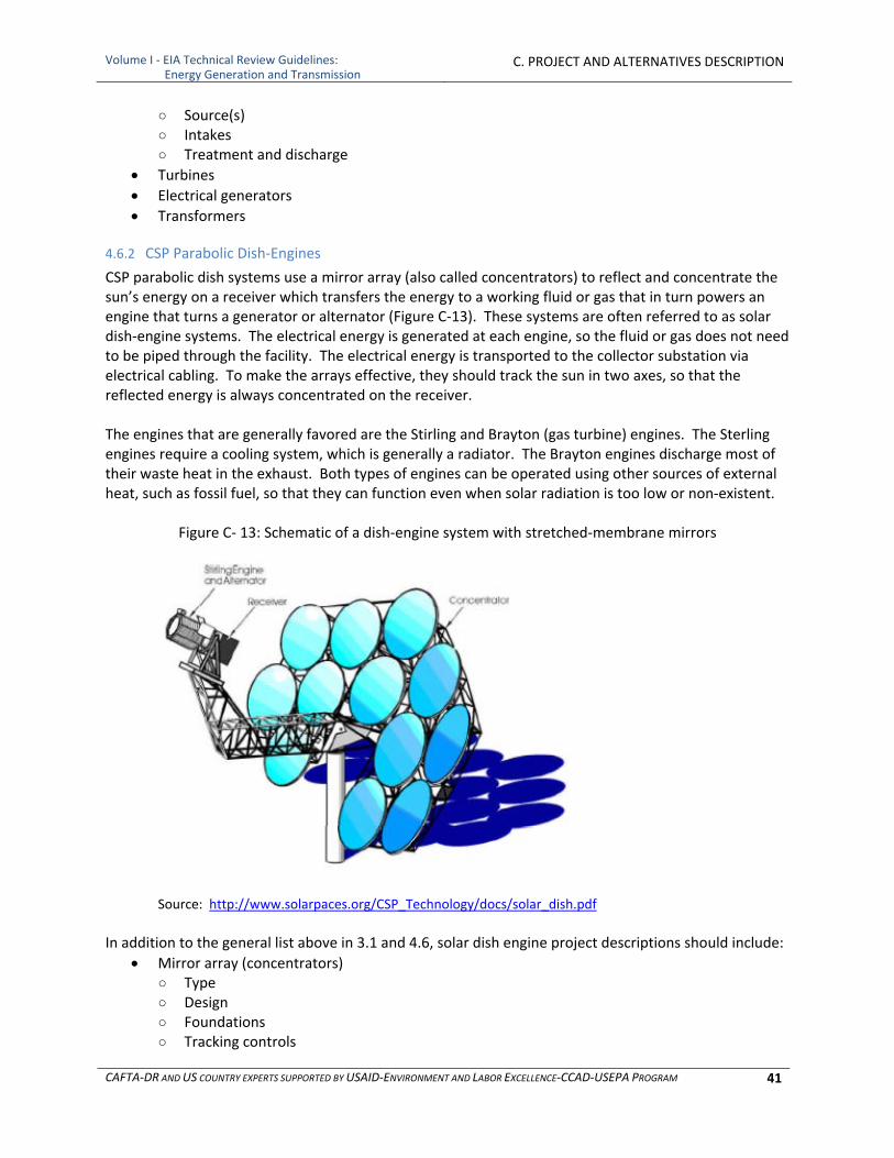
Volume I ‐ EIA Technical Review Guidelines: Energy Generation and Transmission
C. PROJECT AND ALTERNATIVES DESCRIPTION
CAFTA‐DR AND US COUNTRY EXPERTS SUPPORTED BY USAID‐ENVIRONMENT AND LABOR EXCELLENCE‐CCAD‐USEPA PROGRAM 41
○ Source(s) ○ Intakes ○ Treatment and discharge
Turbines
Electrical generators
Transformers
4.6.2 CSP Parabolic Dish‐Engines
CSP parabolic dish systems use a mirror array (also called concentrators) to reflect and concentrate the sun’s energy on a receiver which transfers the energy to a working fluid or gas that in turn powers an engine that turns a generator or alternator (Figure C‐13). These systems are often referred to as solar dish‐engine systems. The electrical energy is generated at each engine, so the fluid or gas does not need to be piped through the facility. The electrical energy is transported to the collector substation via electrical cabling. To make the arrays effective, they should track the sun in two axes, so that the reflected energy is always concentrated on the receiver. The engines that are generally favored are the Stirling and Brayton (gas turbine) engines. The Sterling engines require a cooling system, which is generally a radiator. The Brayton engines discharge most of their waste heat in the exhaust. Both types of engines can be operated using other sources of external heat, such as fossil fuel, so that they can function even when solar radiation is too low or non‐existent.
Figure C‐ 13: Schematic of a dish‐engine system with stretched‐membrane mirrors
Source: http://www.solarpaces.org/CSP_Technology/docs/solar_dish.pdf
In addition to the general list above in 3.1 and 4.6, solar dish engine project descriptions should include:
Mirror array (concentrators) ○ Type ○ Design ○ Foundations ○ Tracking controls
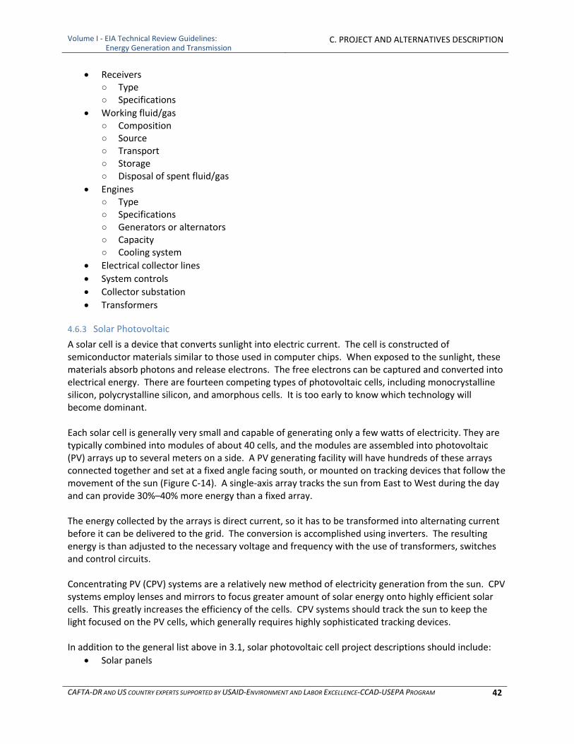
Volume I ‐ EIA Technical Review Guidelines: Energy Generation and Transmission
C. PROJECT AND ALTERNATIVES DESCRIPTION
CAFTA‐DR AND US COUNTRY EXPERTS SUPPORTED BY USAID‐ENVIRONMENT AND LABOR EXCELLENCE‐CCAD‐USEPA PROGRAM 42
Receivers ○ Type ○ Specifications
Working fluid/gas ○ Composition ○ Source ○ Transport ○ Storage ○ Disposal of spent fluid/gas
Engines ○ Type ○ Specifications ○ Generators or alternators ○ Capacity ○ Cooling system
Electrical collector lines
System controls
Collector substation
Transformers
4.6.3 Solar Photovoltaic
A solar cell is a device that converts sunlight into electric current. The cell is constructed of semiconductor materials similar to those used in computer chips. When exposed to the sunlight, these materials absorb photons and release electrons. The free electrons can be captured and converted into electrical energy. There are fourteen competing types of photovoltaic cells, including monocrystalline silicon, polycrystalline silicon, and amorphous cells. It is too early to know which technology will become dominant. Each solar cell is generally very small and capable of generating only a few watts of electricity. They are typically combined into modules of about 40 cells, and the modules are assembled into photovoltaic (PV) arrays up to several meters on a side. A PV generating facility will have hundreds of these arrays connected together and set at a fixed angle facing south, or mounted on tracking devices that follow the movement of the sun (Figure C‐14). A single‐axis array tracks the sun from East to West during the day and can provide 30%–40% more energy than a fixed array. The energy collected by the arrays is direct current, so it has to be transformed into alternating current before it can be delivered to the grid. The conversion is accomplished using inverters. The resulting energy is than adjusted to the necessary voltage and frequency with the use of transformers, switches and control circuits. Concentrating PV (CPV) systems are a relatively new method of electricity generation from the sun. CPV systems employ lenses and mirrors to focus greater amount of solar energy onto highly efficient solar cells. This greatly increases the efficiency of the cells. CPV systems should track the sun to keep the light focused on the PV cells, which generally requires highly sophisticated tracking devices. In addition to the general list above in 3.1, solar photovoltaic cell project descriptions should include:
Solar panels
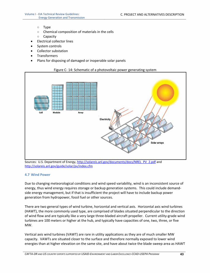
Volume I ‐ EIA Technical Review Guidelines: Energy Generation and Transmission
C. PROJECT AND ALTERNATIVES DESCRIPTION
CAFTA‐DR AND US COUNTRY EXPERTS SUPPORTED BY USAID‐ENVIRONMENT AND LABOR EXCELLENCE‐CCAD‐USEPA PROGRAM 43
○ Type ○ Chemical composition of materials in the cells ○ Capacity
Electrical collector lines
System controls
Collector substation
Transformers
Plans for disposing of damaged or inoperable solar panels
Figure C‐ 14: Schematic of a photovoltaic power generating system
Sources: U.S. Department of Energy, http://solareis.anl.gov/documents/docs/NREL_PV_2.pdf and http://solareis.anl.gov/guide/solar/pv/index.cfm
4.7 Wind Power
Due to changing meteorological conditions and wind speed variability, wind is an inconsistent source of energy, thus wind energy requires storage or backup generation systems. This could include demand‐side energy management, but if that is insufficient the project will have to include backup power generation from hydropower, fossil fuel or other sources. There are two general types of wind turbine, horizontal and vertical axis. Horizontal axis wind turbines (HAWT), the more commonly used type, are comprised of blades situated perpendicular to the direction of wind flow and are typically like a very large three‐bladed aircraft propeller. Current utility‐grade wind turbines are 100 meters or higher at the hub, and typically have capacities of one, two, three, or five MW. Vertical axis wind turbines (VAWT) are rare in utility applications as they are of much smaller MW capacity. VAWTs are situated closer to the surface and therefore normally exposed to lower wind energies than at higher elevation on the same site, and have about twice the blade sweep area as HAWT
Volume I ‐ EIA Technical Review Guidelines: Energy Generation and Transmission
C. PROJECT AND ALTERNATIVES DESCRIPTION
CAFTA‐DR AND US COUNTRY EXPERTS SUPPORTED BY USAID‐ENVIRONMENT AND LABOR EXCELLENCE‐CCAD‐USEPA PROGRAM 44
systems. VAWT systems are, however, gaining in popularity due to easier installation and service, lower visual and sound profile, lower impact on bat and bird populations, and ability to collocate on the footprints of existing HAWT farms thereby generating additional power at a lower incremental cost per additional MW installed. In addition to the general list above in 3.1, wind project descriptions should include:
Wind turbines ○ Type ○ Nameplate capacity and capacity factor. Since wind speed is not constant, a wind farm’s
annual energy production is never as much as the sum of the generator nameplate ratings multiplied by the total hours in a year. The ratio of actual productivity in a year to this theoretical maximum is called the capacity factor. Typical capacity factors are 20 to 40 percent.
○ Height Hub height Rotor diameter Total height
○ Foundations
Electrical collector lines
System controls
Collector substation
Transformers
Energy storage, if applicable
Backup energy source, if applicable
4.8 Geothermal Power
There are three types of geothermal power plants: dry steam, flash steam, and binary cycle. Dry steam power plants pipe steam directly from underground wells to the power plant, where it is directed into a steam turbine/generator unit. These systems require sources of underground steam, which are not common. Flash steam power plants are the most common. They use geothermal reservoirs of water with temperatures greater than 182°C, which flows up through wells under its own pressure. As it flows upward, the pressure decreases and some of the hot water boils into steam. The steam is then separated from the water and used to power a steam turbine/generator. Both dry and flash steam plants are open systems, meaning that the geothermal water and steam is not fully contained and can off‐gas air emissions. As these plants use steam turbines, they have most of components 1‐13 in Figure C‐2. Binary cycle power plants operate on water at lower temperatures of about 107°—182°C. These plants use the heat from the hot water to boil a working fluid, usually an organic compound with a low boiling point. The working fluid is vaporized in a heat exchanger and used to turn a turbine/generator unit or a Sterling engine/generator. The water is then injected back into the ground to be reheated. The water and the working fluid are kept separated during the whole process, so there are little or no air emissions.
Volume I ‐ EIA Technical Review Guidelines: Energy Generation and Transmission
C. PROJECT AND ALTERNATIVES DESCRIPTION
CAFTA‐DR AND US COUNTRY EXPERTS SUPPORTED BY USAID‐ENVIRONMENT AND LABOR EXCELLENCE‐CCAD‐USEPA PROGRAM 45
Geothermal electric plants have until recently been built exclusively on the edges of tectonic plates where high temperature geothermal resources are available near the surface. The development of binary cycle power plants and improvements in drilling and extraction technology may enable enhanced geothermal systems over a much greater geographical range. In addition to the general list above in 3.1, geothermal project descriptions should include:
Descriptions of all geothermal wells, including both exploratory wells and production wells ○ Number ○ Location ○ Depth and diameter ○ Design ○ Materials used
Equipment used for drilling wells ○ Disposition of waste material during drilling ○ Water intakes ○ Water discharges including reinjection ○ Turbines and electrical generators ○ Transformers and transmission lines
Piping for water conveyance from wells to plant
Heat exchangers
Boilers
Steam controls
Cooling system
Cooling water ○ Quantity ○ Source(s) ○ Intakes ○ Treatment and discharge
Treatment of “spent” thermal water ○ Type (reinjection or surface discharge) ○ Locations ○ Specifications ○ Treatment, if applicable
Turbines
Electrical generators
Transformers
Air emissions controls for “open” systems
5 ELECTRIC POWER TRANSMISSION
Electric power transmission is the bulk transfer of electrical energy between the point of generation and multiple substations near a populated area or load center. Electric power transmission allows distant energy sources to be connected to consumers in population centers, and may allow exploitation of low‐grade fuel resources such as coal that would otherwise be too costly to transport to generating facilities. A power transmission network is referred to as a “grid.” Multiple redundant lines between points on the grid are provided so that there are a variety of routes from any power plant to any load center. The

Volume I ‐ EIA Technical Review Guidelines: Energy Generation and Transmission
C. PROJECT AND ALTERNATIVES DESCRIPTION
CAFTA‐DR AND US COUNTRY EXPERTS SUPPORTED BY USAID‐ENVIRONMENT AND LABOR EXCELLENCE‐CCAD‐USEPA PROGRAM 46
specific routing of electricity on the grid at any time is based on the economics of the transmission path and the cost of power. Usually transmission lines use three phase alternating current (AC). High voltage direct current systems are used for long distance transmission, or some undersea cables, or for connecting two different AC networks. Electricity is usually transmitted at high voltages (110 KV or above) to reduce the energy lost in transmission. Transmission may be via overhead or underground lines. Overhead transmission lines are made of bare metal, uninsulated conductors. The conductor material is nearly always an aluminum alloy, made into several strands and possibly reinforced with steel strands. Improved conductor material and shapes are regularly used to allow increased capacity and modernize transmission circuits. Because the lines are uninsulated, minimum clearances should be observed to maintain safety both in terms of access from the ground and from the airspace. Although more costly and therefore less used, burying power cables underground can assist the transmission of power across:
Densely populated urban areas
Areas where land is unavailable or planning consent is difficult (Underground cables need a narrower surrounding strip of about 1 to 10 meters to install, whereas an overhead line requires a surrounding strip of about 20 to 200 meters wide to be kept permanently clear for safety, maintenance and repair)
Rivers and other natural obstacles
Land with outstanding natural or environmental heritage
Areas of significant or prestigious infrastructural development
Areas with high risk of damage from severe weather conditions (mainly wind)
Areas with concerns about emission of electromagnetic fields (EMF). (All electric currents generate EMF, but the shielding provided by the earth surrounding underground cables restricts their range and power.)
Most high‐voltage underground cables for power transmission that are currently sold on the market are insulated by a sheath of cross‐linked polyethylene (XLPE). Some cable may have a lead or aluminum jacket in conjunction with XLPE insulation to allow for fiber optics to be seamlessly integrated within the cable. In addition to higher installation costs, underground lines also have higher maintenance and operation costs. Whereas finding and repairing overhead wire breaks can be accomplished in hours, underground repairs can take days or weeks, and for this reason redundant lines are run. Operations are more difficult since the high reactive power of underground cables produces large charging currents and so makes voltage control more difficult. In addition to the general list above in 3.1, transmission project descriptions should include:
All Transmission ○ Voltage carried ○ Number of lines ○ Total length of line in km (disaggregated by overhead and buried if applicable) ○ The grid into which the transmission line will connect and the points of interconnection
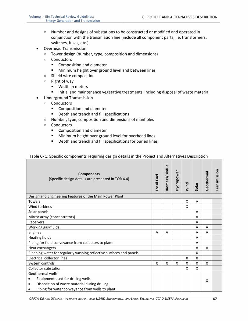
Volume I ‐ EIA Technical Review Guidelines: Energy Generation and Transmission
C. PROJECT AND ALTERNATIVES DESCRIPTION
CAFTA‐DR AND US COUNTRY EXPERTS SUPPORTED BY USAID‐ENVIRONMENT AND LABOR EXCELLENCE‐CCAD‐USEPA PROGRAM 47
○ Number and designs of substations to be constructed or modified and operated in conjunction with the transmission line (include all component parts, i.e. transformers, switches, fuses, etc.)
Overhead Transmission ○ Tower design (number, type, composition and dimensions) ○ Conductors Composition and diameter Minimum height over ground level and between lines
○ Shield wire composition ○ Right of way Width in meters Initial and maintenance vegetative treatments, including disposal of waste material
Underground Transmission ○ Conductors Composition and diameter Depth and trench and fill specifications
○ Number, type, composition and dimensions of manholes ○ Conductors Composition and diameter Minimum height over ground level for overhead lines Depth and trench and fill specifications for buried lines
Table C‐ 1: Specific components requiring design details in the Project and Alternatives Description
Components (Specific design details are presented in TOR 4.4)
Fossil Fuel
Biomass/Biofuel
Hydropower
Wind
Solar
Geotherm
al
Tran
smission
Design and Engineering Features of the Main Power Plant
Towers X A
Wind turbines X
Solar panels A
Mirror array (concentrators) A
Receivers A
Working gas/fluids A A
Engines A A A A
Heating fluids A
Piping for fluid conveyance from collectors to plant A
Heat exchangers A A
Cleaning water for regularly washing reflective surfaces and panels X
Electrical collector lines X X
System controls X X X X X X
Collector substation X X
Geothermal wells
Equipment used for drilling wells
Disposition of waste material during drilling
Piping for water conveyance from wells to plant
X
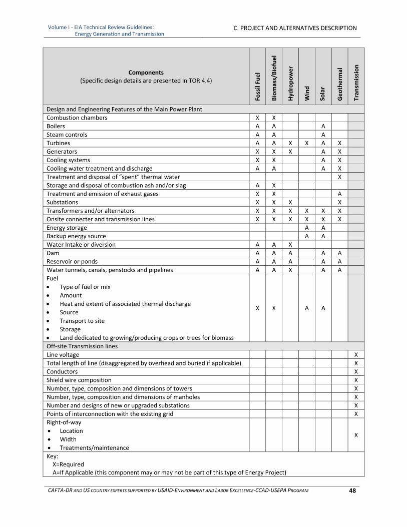
Volume I ‐ EIA Technical Review Guidelines: Energy Generation and Transmission
C. PROJECT AND ALTERNATIVES DESCRIPTION
CAFTA‐DR AND US COUNTRY EXPERTS SUPPORTED BY USAID‐ENVIRONMENT AND LABOR EXCELLENCE‐CCAD‐USEPA PROGRAM 48
Components (Specific design details are presented in TOR 4.4)
Fossil Fuel
Biomass/Biofuel
Hydropower
Wind
Solar
Geotherm
al
Tran
smission
Design and Engineering Features of the Main Power Plant
Combustion chambers X X
Boilers A A A
Steam controls A A A
Turbines A A X X A X
Generators X X X A X
Cooling systems X X A X
Cooling water treatment and discharge A A A X
Treatment and disposal of “spent” thermal water X
Storage and disposal of combustion ash and/or slag A X
Treatment and emission of exhaust gases X X A
Substations X X X X
Transformers and/or alternators X X X X X X
Onsite connecter and transmission lines X X X X X X
Energy storage A A
Backup energy source A A
Water Intake or diversion A A X
Dam A A A A A
Reservoir or ponds A A A A A
Water tunnels, canals, penstocks and pipelines A A X A A
Fuel
Type of fuel or mix
Amount
Heat and extent of associated thermal discharge
Source
Transport to site
Storage
Land dedicated to growing/producing crops or trees for biomass
X X A A
Off‐site Transmission lines
Line voltage X
Total length of line (disaggregated by overhead and buried if applicable) X
Conductors X
Shield wire composition X
Number, type, composition and dimensions of towers X
Number, type, composition and dimensions of manholes X
Number and designs of new or upgraded substations X
Points of interconnection with the existing grid X
Right‐of‐way
Location
Width
Treatments/maintenance
X
Key: X=Required A=If Applicable (this component may or may not be part of this type of Energy Project)
Volume I ‐ EIA Technical Review Guidelines: Energy Generation and Transmission
C. PROJECT AND ALTERNATIVES DESCRIPTION
CAFTA‐DR AND US COUNTRY EXPERTS SUPPORTED BY USAID‐ENVIRONMENT AND LABOR EXCELLENCE‐CCAD‐USEPA PROGRAM 49
6 TRANSPORTATION FACILITIES
All new and existing transportation facilities should be addressed in this section, including roads, trains, conveyors, and waterways. If the project will require new access routes, these should also be included in this section. This section should contain a map of transportation routes that will be constructed and maintained by the project, indicating the type and size of each route as well as the timing of its construction.
6.1 Roads
There are several types of roads that may be used, maintained, upgraded or constructed as part of the project, including primary and secondary roads used to bring in construction materials and provide facility access and smaller roads used for accessing remote sites for monitoring. For each of these roads, the project description should include maps and specific design information including:
Identify all existing roads to be used ○ Traffic volume, operating speeds and trip times
Detailed information on any roads to be constructed ○ Location ○ Timing of construction ○ Road surface and shoulder width and barriers ○ Grade specifications ○ Construction methods including clearing and grubbing ○ Construction materials ○ Compaction specifications ○ Stream crossings and associated designs ○ Animal crossings ○ Sedimentation and erosion prevention structures and practices ○ Stabilization methods for cuts and fills ○ Typical elevations for each type and situation of road displaying construction materials,
levels of compaction and erosion and sedimentation features ○ Borrow pits ○ Closure plan, if applicable ○ Traffic volume, operating speeds and trip times
Dust control for construction and operation
Maintenance
Roster for construction and maintenance equipment, specifying type and quantity by size, motor size, and fuel requirements
6.2 Transportation by Rail
If a railroad is to be used or constructed to bring in construction materials or fuels, information will need to be provided concerning its construction and alignment, including a map of its location. Necessary design criteria include:
Timing of construction
Roadbed width
Roadbed construction method including clearing and grubbing
Roadbed materials
Grade and maximum grade
Volume I ‐ EIA Technical Review Guidelines: Energy Generation and Transmission
C. PROJECT AND ALTERNATIVES DESCRIPTION
CAFTA‐DR AND US COUNTRY EXPERTS SUPPORTED BY USAID‐ENVIRONMENT AND LABOR EXCELLENCE‐CCAD‐USEPA PROGRAM 50
Tightest curves
Track construction materials
Turnouts and sidings
Railroad communications and signaling
Designs, including typical elevations of: ○ Road crossings ○ Stream crossings and associated designs ○ Sedimentation and erosion prevention structures and practices
Stabilization methods for cuts and fills
Maintenance
Dust control measures during construction
Borrow pits ○ Location and size (area and volume of material) ○ Operation ○ Sedimentation and erosion controls ○ Closure plan
Construction equipment roster specifying type and quantity by: size, motor size, and fuel requirements for each type of equipment
An operations program should address traffic volume, operating speeds and trip times. The train itself should be described in terms of the type and amount of cars and locomotives, the overall length, the average tons per car and per train, the number of trips per week it would be operated. If an existing railroad is to be used, improvements and changes to the existing operations will need to be indicated in terms of the aspects outlined in the above paragraphs.
6.3 Conveyors
Conveyors may be used to transport fuel to the site or to move fuel onsite. Maps showing the locations and lengths of all conveyors and complete design details, including source of energy for operation and dust control measures, should be included in this section. Where conveyors cross water bodies, conveyors should be covered to prevent water contamination.
6.4 Pipelines
If pipelines will be used to deliver fuel to the site, information should be presented in this section on the location, design, construction and operation of the pipelines, including:
Maps showing the location of the pipeline
Source of fuel
Stream and road crossing designs
Monitoring
7 ONSITE SUPPORT FACILITIES
Energy generation projects may have many ancillary structures at the plant facility such as office, toilet facilities, bath houses, laboratories, shops, vehicle maintenance areas, warehouses, storage buildings, storage areas, back up power generation, fuel preparation and cleaning areas, fences and fueling

Volume I ‐ EIA Technical Review Guidelines: Energy Generation and Transmission
C. PROJECT AND ALTERNATIVES DESCRIPTION
CAFTA‐DR AND US COUNTRY EXPERTS SUPPORTED BY USAID‐ENVIRONMENT AND LABOR EXCELLENCE‐CCAD‐USEPA PROGRAM 51
facilities. If the site is in a remote location, he facility may also construction camps (which may apply to transmission as well as generation projects) and have employee housing. Many of these facilities will require water systems, sewage treatment facilities and solid waste collection and disposal. Some of them, such as vehicle maintenance, storage areas, power generation, and fueling facilities, may generate hazardous wastes including solvents, lubricants, hydraulic fluids, anti‐freeze, spent tires and wash water. Others, such as warehouses, storage buildings and fueling stations may store hazardous products (fuels, chemicals, heat transfer fluids, working fluids and explosives) that will require containment and emergency procedures. The Project and Alternatives Description should include a description and digitized site drawing of each facility including its location, design, and associated services (water, sewage, solid waste disposal, etc.). It should include a description of areas that will be temporarily disturbed during construction as well as those areas that will be occupied by the facilities. It should detail how wastes from these facilities will be managed and disposed. This section should contain and inventory of all chemical, toxic or hazardous substances that will be used during operation of the facilities including the active elements, means of storage, and safety precautions to be used during transport and handling. It should include containment designs and emergency response provisions for all facilities in which hazardous substances will be stored and handled as well as those that may generate hazardous wastes. This section should also contain the project:
Hazardous Waste Management Program
Wastewater Management Program
Solid Waste Management Program
Spill Prevention Program
8 CLOSURE AND DECOMISSIONING PLAN
The project description should include at least a general closure and decommissioning plan describing the plan for closing the facility, decommissioning the machinery and structures, and restoring the land surface. The plan should contain a commitment to contact the proper regulatory agency(ies) at the time of closure to obtain the environmental applicable guidelines to carry out the closure or decommissioning, recognizing that terms of closure may be very different when this phase approaches.

Volume I ‐ EIA Technical Review Guidelines: Energy Generation and Transmission
C. PROJECT AND ALTERNATIVES DESCRIPTION
CAFTA‐DR AND US COUNTRY EXPERTS SUPPORTED BY USAID‐ENVIRONMENT AND LABOR EXCELLENCE‐CCAD‐USEPA PROGRAM 52
9 MANPOWER AND LOCAL PURCHASES
The project description should present information on the number and type of employees that will be hired by the project, during all phases of its life, and the level at which the project will be relying upon local businesses to provide goods and services. This information is necessary for assessing the social impacts of the proposed mine. For both construction and operation, this information should include:
Number and type of employees (by local hire and non‐local hire) by field of expertise
Days per week
Hours per day
Shifts per day
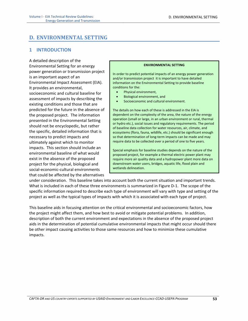
Volume I ‐ EIA Technical Review Guidelines: Energy Generation and Transmission
D. ENVIRONMENTAL SETTING
CAFTA‐DR AND US COUNTRY EXPERTS SUPPORTED BY USAID‐ENVIRONMENT AND LABOR EXCELLENCE‐CCAD‐USEPA PROGRAM 53
ENVIRONMENTAL SETTING In order to predict potential impacts of an energy power generation and/or transmission project it is important to have detailed information on the Environmental Setting to provide baseline conditions for the:
Physical environment,
Biological environment, and
Socioeconomic and cultural environment. The details on how each of these is addressed in the EIA is dependent on the complexity of the area, the nature of the energy operation (small or large, in an urban environment or rural, thermal or hydro etc.), social issues and regulatory requirements. The period of baseline data collection for water resources, air, climate, and ecosystems (flora, fauna, wildlife, etc.) should be significant enough so that determination of long‐term impacts can be made and may require data to be collected over a period of one to five years. Special emphasis for baseline studies depends on the nature of the proposed project, for example a thermal electric power plant may require more air quality data and a hydropower plant more data on downstream water users, bridges, aquatic life, flood plain and wetlands delineation.
D. ENVIRONMENTAL SETTING
1 INTRODUCTION
A detailed description of the Environmental Setting for an energy power generation or transmission project is an important aspect of an Environmental Impact Assessment (EIA). It provides an environmental, socioeconomic and cultural baseline for assessment of impacts by describing the existing conditions and those that are predicted for the future in the absence of the proposed project. The information presented in the Environmental Setting should not be encyclopedic, but rather the specific, detailed information that is necessary to predict impacts and ultimately against which to monitor impacts. This section should include an environmental baseline of what would exist in the absence of the proposed project for the physical, biological and social‐economic‐cultural environments that could be affected by the alternatives under consideration. This baseline takes into account both the current situation and important trends. What is included in each of these three environments is summarized in Figure D‐1. The scope of the specific information required to describe each type of environment will vary with type and setting of the project as well as the typical types of impacts with which it is associated with each type of project. This baseline aids in focusing attention on the critical environmental and socioeconomic factors, how the project might affect them, and how best to avoid or mitigate potential problems. In addition, description of both the current environment and expectations in the absence of the proposed project aids in the determination of potential cumulative environmental impacts that might occur should there be other impact causing activities to those same resources and how to minimize these cumulative impacts.
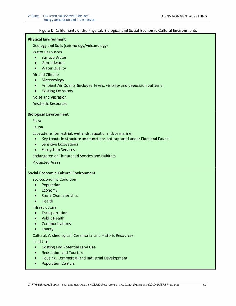
Volume I ‐ EIA Technical Review Guidelines: Energy Generation and Transmission
D. ENVIRONMENTAL SETTING
CAFTA‐DR AND US COUNTRY EXPERTS SUPPORTED BY USAID‐ENVIRONMENT AND LABOR EXCELLENCE‐CCAD‐USEPA PROGRAM 54
Figure D‐ 1: Elements of the Physical, Biological and Social‐Economic‐Cultural Environments
Physical Environment
Geology and Soils (seismology/volcanology)
Water Resources
Surface Water
Groundwater
Water Quality
Air and Climate
Meteorology
Ambient Air Quality (includes levels, visibility and deposition patterns)
Existing Emissions
Noise and Vibration
Aesthetic Resources
Biological Environment
Flora
Fauna
Ecosystems (terrestrial, wetlands, aquatic, and/or marine)
Key trends in structure and functions not captured under Flora and Fauna
Sensitive Ecosystems
Ecosystem Services
Endangered or Threatened Species and Habitats
Protected Areas
Social‐Economic‐Cultural Environment
Socioeconomic Condition
Population
Economy
Social Characteristics
Health
Infrastructure
Transportation
Public Health
Communications
Energy
Cultural, Archeological, Ceremonial and Historic Resources
Land Use
Existing and Potential Land Use
Recreation and Tourism
Housing, Commercial and Industrial Development
Population Centers
Volume I ‐ EIA Technical Review Guidelines: Energy Generation and Transmission
D. ENVIRONMENTAL SETTING
CAFTA‐DR AND US COUNTRY EXPERTS SUPPORTED BY USAID‐ENVIRONMENT AND LABOR EXCELLENCE‐CCAD‐USEPA PROGRAM 55
2 PHYSICAL ENVIRONMENT
2.1 Geology and Soils
Documentation of geology, soils and topography at the power plant site and along the transmission route should be presented in the Environmental Setting in narrative and tabular form, cross‐sections, and on maps on which potential impacts can be overlaid. Information on geology, soils and topography is typically available from the responsible ministries and academia. A site specific soil survey and test boring may be required if such data is not reliable, adequate or readily available. Seismic zone determination, frequency and intensity of earthquakes and tremors, maximum credible earthquake, and maximum probable earthquake data should be included in this subsection, particularly for projects that include large structures, fuel storage, impoundment dams, canals and penstocks. If the power plant site or right of way is located within a radius of 30 km from an active volcanic emission center information should also be presented on the general volcanic features of the area near the site, historical eruptions, and period of recurrence, type of eruptions, and areas most likely to be affected by eruptions. During baseline data collection it is important to collect information on the erosion potential of the soils, the chemical composition of each soil type, and the availability and suitability of soils for use during restoration and revegetation. If a soil survey is necessary, it should include: soil type, grain size distribution, engineering properties including stability, depth of various horizons, permeability, erosion and sedimentation potential, current uses, fertility, and vegetative growth potential, etc. Particular care should be given to studying tropical soil structure and chemistry since such soils are very sensitive to degradation. All energy generation and transmission projects have the potential to modify runoff and sedimentation, so it is important that enough soil data is provided so that runoff and sediment transport models can provide meaningful results.
2.2 Water Resources
2.2.1 Surface Water
The Environmental Setting section should include an evaluation of surface water resources in the direct vicinity of the project. This should include the analysis of the watershed characteristics including water quality, flow characteristics, drainage patterns and runoff characteristics, soils, vegetation, and impervious cover (see box below). This information should be included on topographic maps which should include all surface water resources and floodplains in the area of influence overlaid with the proposed project facilities including all monitoring stations and discharge points. All nearby rivers, streams, wetlands, lakes and other water bodies should be identified as well as the current uses of the water. All existing historic surface water flow data in the area of influence should be collected, compiled and analyzed to present information on:
Average daily, monthly and annual flows in cubic meters per second (m3/s)
Maximum monthly flows in m3/s
Minimum monthly flow in m3/s
2‐, 10‐, 25‐, 50‐ and 100‐year runoff events and associated floodplains for streams and rivers
Seasonal fluctuations in area and volume of wetlands, lakes and reservoirs

Volume I ‐ EIA Technical Review Guidelines: Energy Generation and Transmission
D. ENVIRONMENTAL SETTING
CAFTA‐DR AND US COUNTRY EXPERTS SUPPORTED BY USAID‐ENVIRONMENT AND LABOR EXCELLENCE‐CCAD‐USEPA PROGRAM 56
For hydroelectric projects that alter the flow of rivers or streams or for other projects that will require a significant amount of operational water (e.g., thermal plants with large water demand for cooling), the Environmental Setting section should also present inventories of consumptive and non‐consumptive use (including types of uses by volume of use) and a calculation of the current surface water balance.
An important aspect of an EIA is the development and presentation of baseline surface water quality monitoring data, which should be collected prior to disturbance. All existing historic water quality data for the area of influence should be collected and compiled to help define the baseline. For hydroelectric projects or projects that will have significant wastewater discharges, including thermal discharges, these data should be augmented by the results of a surface water quality monitoring program conducted at specific sites in the project area. Monitoring of baseline conditions should take place for at least a year so that seasonal fluctuations in flow and water quality can be determined.
Watershed Approach It is important to evaluate the environmental setting and potential impacts of an energy generation and/or transmission project in relation to the entire watershed. Watershed management involves both the quantity of water (surface and ground water) available and the quality of these waters. Understanding the impact of the project on both the quantity and quality of water should take into account the cumulative impacts of other activities in the same watershed. A watershed‐based impact assessment approach involves the following 10 steps. Steps 1‐6 apply directly to establishing the Environmental Setting. Steps 7‐9 are concerned with assessing the impacts of the project. Step 10 insures that stakeholders are involved in the design and analysis of the project.
1. Identify and map the boundaries of the watershed in which the project is located and place the project boundaries on the map.
2. Identify the drainage pattern and runoff characteristics in the watershed. 3. Identify the downstream rivers, streams, wetlands, lakes and other water bodies. 4. Determine the existing quality of the water in these resources. 5. Determine the current and projected consumptive and non‐consumptive uses of the water in
these resources:
Drinking water
Irrigation
Aquaculture
Industry
Recreation
Support of aquatic life
Navigation 6. Determine the nature and extent of pollutants discharged throughout the watershed. 7. Determine the anticipated additional pollutants discharge from the proposed activity. 8. Estimate the impact of the project on the consumptive and non‐consumptive use of water. 9. Identify other potential additional developments planned or projected for the watershed. 10. Identify stakeholders involved in watershed and encourage their participation in project design.
Volume I ‐ EIA Technical Review Guidelines: Energy Generation and Transmission
D. ENVIRONMENTAL SETTING
CAFTA‐DR AND US COUNTRY EXPERTS SUPPORTED BY USAID‐ENVIRONMENT AND LABOR EXCELLENCE‐CCAD‐USEPA PROGRAM 57
Prior to implementing any baseline monitoring program, a “Sampling and Analysis Plan” should be developed. This plan would define sample locations, sampling techniques, chemical parameters, and analytical methods. Sample locations should be located upstream and immediately downstream of potential pollutant sources (including dam and diversion outlets). The selection of chemical parameters to be monitored is dependent on the nature of the pollutants to be discharged to surface water. Monitored parameters may include: field parameters (pH, specific conductance, temperature, etc.) and laboratory analyzed parameters (total dissolved solids, total suspended solids, selected trace metals, major cations/anions), and perhaps other parameters depending on the nature of the operation.
2.2.2 Groundwater
The extent of the characterization of the baseline groundwater resources necessary for energy projects varies greatly with the type of project. Wind and transmission lines have virtually no potential impacts on groundwater, so do not require baseline information on groundwater. Other projects may have impacts on groundwater quality or quantity or both, and therefore require more information on groundwater conditions. Hydroelectric projects that create reservoirs can obviously have an effect on the quantity of water in unconfined surface aquifers below the reservoir sites. The storage of fuel at thermal/combustion plants can potentially impact groundwater quality. Consumptive use of water by thermal power plants and discharge of cooling waters into cooling ponds can have impacts on both the quantity and quality of groundwater. For those projects that can impact groundwater quantity, the Environmental Setting section should include descriptions of aquifers (bedrock and alluvial) including their geology, aquifer characteristics (hydraulic characteristics), and the flow regime/direction for each aquifer. The influences of geologic structures (faults, contacts, bedrock fracturing, etc) and surface water bodies on the aquifers should also be mapped or determined. All wells and springs in the area should be mapped and information provided on their flows, water levels and uses. These maps should be overlaid with the topography and should cover the area of influence. For wells, depth and construction information should be presented. The EIA should also indicate which ones have been monitored and which ones will be monitored during and after operations. This information can then be used, along with the locations of potential recharge and contaminant sources, to determine potential impacts. For those projects that can impact groundwater quality or quality, the information on vadose zone and aquifer characteristics should include sufficient data on the parameters to allow aquifer and vadose zone modeling. The necessary parameters will depend on the type modeling that will be required, which should be selected based on the nature of the potential impacts. For instance, a hydroelectric project with a reservoir will require sufficient data to run a groundwater flow model (analytical or numeric) to determine the potential impacts to nearby wells. A project with cooling ponds or a project with storage of solid or liquid fuel should use a groundwater flow model and a hydrochemistry model to determine the potential impacts. Any model used requires good data to make realistic predictions. As with surface water, an important aspect of the EIA is the development and presentation of baseline water monitoring data, collected prior to disturbance. All existing data on quantity and quality of water from springs and wells in the vicinity of the project should be collected and reported in the EIA to help define the baseline. Water quality in all springs and nearby wells should be reported at least quarterly for at least one year (and preferably two years) to determine baseline quality and chemistry. In
Volume I ‐ EIA Technical Review Guidelines: Energy Generation and Transmission
D. ENVIRONMENTAL SETTING
CAFTA‐DR AND US COUNTRY EXPERTS SUPPORTED BY USAID‐ENVIRONMENT AND LABOR EXCELLENCE‐CCAD‐USEPA PROGRAM 58
addition, maps showing variations on a seasonal basis of water quality and groundwater levels should be included. For projects that can potentially have impacts on groundwater quality, if data for existing wells and springs are not available, a “Sampling and Analysis Plan” should be prepared and a sampling program implemented. The sampling should include water levels and flow rates as well as other parameters such as pH, temperature, and specific conductance. The selection of chemical parameters to be monitored is dependent on the nature of the activity and its potential to contaminate the aquifer.
2.3 Air and Climate
2.3.1 Climate and Meteorology
Understanding climate and meteorology in the project area is important for the design of a long‐term air monitoring program (necessary for all power plants at which fuel is combusted), developing a water balance for the site, and designing water/erosion control structures. During the baseline data collection period, climatic data from local weather stations should be gathered and analyzed. These data should include at least historic rainfall data (total precipitation, rainfall intensity, and duration), wind direction and speed, solar radiation, evaporation rates, barometric pressure, and temperature variations. For large projects, if no data are available near the site, a weather station should be established and baseline data should be collected for at least one year to reflect the seasonal changes at the site. All sampling site and weather station locations should be depicted on a map in the EIA.
2.3.2 Ambient Air Quality and Existing Emissions
Baseline air quality data is critical for all power facilities that combust fuel, as it will be used to assess air quality impacts from stack emissions. For such plants the air pollutants of primary concern will be particulate matter (PM), sulfur dioxide (SO2), oxides of nitrogen (NOX), carbon monoxide (CO) and greenhouse gas emissions (primarily as CO2 , nitric oxide [N2O] and methane [CH4]). Air monitoring should be conducted, both upwind and downwind of the facility. Monitoring should include the use of high volume samplers and/or other methods to collect samples of air borne particulates and gases that may be emitted from the facility. Sampling may be either continuous or by grab or composite samples. Selection of monitoring locations requires an understanding of site‐specific meteorological conditions that can affect pollutant fate and transport. This subsection of the Environmental Setting should also include an inventory of all current air pollutant emission sources (including greenhouse gases) in the area of influence. The inventory should include locations of emissions and current emission levels.
2.4 Noise and Vibration
If possible noise and vibration impacts are suspected (i.e., if the project will generate significant noise and there are nearby receptors), baseline noise measurements should be included in the Environmental Setting section of the EIA. If they do not exist, they should be taken at representative points of reception prior to start of construction. Noise levels in and around sensitive habitats and areas of human habitation also should be taken. A point of reception or receptor may be defined as any point on or near the premises occupied by persons or animals where extraneous noise and/or vibration are received. Examples of receptor
Volume I ‐ EIA Technical Review Guidelines: Energy Generation and Transmission
D. ENVIRONMENTAL SETTING
CAFTA‐DR AND US COUNTRY EXPERTS SUPPORTED BY USAID‐ENVIRONMENT AND LABOR EXCELLENCE‐CCAD‐USEPA PROGRAM 59
locations include: permanent or seasonal residences; hotels/motels; schools and daycare facilities; hospitals and nursing homes; places of worship; parks and campgrounds; sensitive habitats such as breeding, birthing or nesting areas. Noise monitoring programs should be designed and conducted by trained specialists. The monitoring periods should be sufficient for statistical analysis and may last 48 hours or cover differing time periods within several days, including weekday and weekend workdays. Noise monitoring should be carried out using a Type 1 or 2 sound level meters meeting all appropriate IEC standards and capable of logging the type of data required by the design (continuously over the monitoring period, or hourly, or more frequently, as appropriate). Monitors should be located approximately 1.5 meters above the ground.
2.5 Aesthetic Resources
Baseline information on views and vistas that could be impacted by the proposed project should be identified in the Environmental Setting. Vistas and views include, but are not limited to mountains, waterfalls, skylines including sunrises and sunsets, and cultural, archeological, and historical structures. The location of these views and vistas can be documented by presenting panoramic views of them from potential viewpoints such as communities, roads, and designated scenic viewing areas. Narrative descriptions of existing visual assets are also useful as the specific importance of a view may not be obvious to a non‐local viewer. In addition, this subsection should present information on existing visibility in the project area. This subsection should present panoramic photos of the proposed facility site from potential viewpoints such as communities, roads, and designated scenic viewing areas. These photos can be used to establish the views without the facility and provide a baseline on which the facility can be overlaid. Information should also be presented in the subsection on light pollution from existing sources in the project area including communities, factories, street lights, etc. Where objective measurement is desired, light levels can be quantified by field measurement or mathematical modeling, with results typically displayed as an isophote map or light contour map.
3 BIOLOGICAL ENVIRONMENT
The Environmental Setting information for biological resources should include information on aquatic, terrestrial and wetland ecosystems in the vicinity. The challenge for development of an EIA for energy projects is to qualitatively evaluate and record the local ecosystems and their biodiversity, often in the absence of clear protective designations. This involves looking at a range of criteria to determine whether the site is of local, regional, national or international importance. In evaluating baseline conditions of aquatic, terrestrial and wetlands ecosystems (as appropriate for the project area) the following steps should be taken:
Obtain readily available information on biodiversity through review of maps, reports and publications available from government agencies, universities, NGOs or online.
Produce maps of all habitats and key species locations, protected areas, migration corridors, seasonal use areas (mating, nesting, etc.)
Describe timing of important seasonal activities (nesting, breeding, migration, etc.) for species that could be affected by the energy project activities.
Determine the following ecological characteristics of the project area:

Volume I ‐ EIA Technical Review Guidelines: Energy Generation and Transmission
D. ENVIRONMENTAL SETTING
CAFTA‐DR AND US COUNTRY EXPERTS SUPPORTED BY USAID‐ENVIRONMENT AND LABOR EXCELLENCE‐CCAD‐USEPA PROGRAM 60
○ Size of each habitat ○ Existing condition of each habitat and its value ○ Species/habitat richness ○ Fragility of the ecosystem ○ Population size for important species or species of concern ○ Rarity of any species or habitat
Identify whether the site or surrounding area falls within a protected area – that is, whether it is a natural area designated by the government as having special protection (National Park, National Forest, Wildlife Reserve, etc.).
Identify whether the site or surrounding area is not currently protected but has been identified by governments or other stakeholders as having a high biodiversity conservation priority.
Identify whether the site or surrounding area has particular species that may be under threat.
Review and summarize relevant legal provisions relating to biodiversity, species protection and protected area management (including requirements of any management plans that exist for designated protected areas).
Elicit the views of stakeholders on whether the site or surrounding area has rare, threatened, or culturally important species.
The evaluation of any ecosystem whether aquatic, terrestrial, or wetland is dependent upon professional judgment and requires the involvement of trained ecologists. In areas where there is little or no information available, considerable field work is required to collect the information listed above.
3.1 Flora
An inventory of flora within the project boundaries and project area of influence should be conducted during the collection of baseline information for the Environmental Setting. The best sources of data on local fauna are local peoples, relevant ministries (forestry, agriculture and environment), and academia. The results of the inventory should be presented as vegetative maps of the area, which usually will also serve to provide a map of the relevant ecosystems. Narrative descriptions of vegetative types should also be included, identifying species endemism, keystone species (species that play a critical role in maintaining the structure of an ecological community and whose impact on the community is greater than would be expected based on its relative abundance or total biomass) and species rarity including identification of those that may be threatened or endangered. Of particular importance is the delineation of wetlands as they are sensitive habitats and quite important with respect to cleaning water that passes through them as well as serving as buffers against flooding elsewhere in the hydrological basin. Already identified in surface water subsection, in this subsection the ecological characteristics should be presented.
3.2 Fauna
An inventory of aquatic and terrestrial fauna within the project boundaries and project area of influence should also be conducted during the collection of baseline information for the Environmental Setting. The best sources of data on local fauna are local peoples, relevant ministries (forestry, agriculture and environment), and academia. The results of the inventory should present information on the status (i.e. endemic, migratory, exotic, keystone, threatened, endangered, etc.) and life history characteristics (mating and brooding seasons,

Volume I ‐ EIA Technical Review Guidelines: Energy Generation and Transmission
D. ENVIRONMENTAL SETTING
CAFTA‐DR AND US COUNTRY EXPERTS SUPPORTED BY USAID‐ENVIRONMENT AND LABOR EXCELLENCE‐CCAD‐USEPA PROGRAM 61
migratory patterns, etc.) of the species identified as residing in the area. For terrestrial species, maps should be included identifying:
Breeding areas
Nesting and calving areas
Migratory corridors (if applicable) Information on fish, mussel, macroinvertebrate and other aquatic species should include:
Spatial and temporal distribution
Species life stage composition
Standing crop
Age and growth data
Spawning timing run Understanding site specific conditions and geographic location for a proposed wind turbine/farm is very important. Several studies support the importance of site‐specific information (e.g., geographic features, existing migratory patterns, surveying for features such as caves and/or abandoned mines that may be used by bats near a proposed site) are an important indicator that possible mitigation may be needed to avoid or minimize potential loss of bats and birds, which in turn can have important impacts on both agriculture and public health.
3.3 Ecosystems
Beyond looking at flora and fauna independently, an EIA needs to be integrated, i.e. to address the relationships between biophysical, social and economic aspects in assessing project impacts (IAIA 1999). Addressing these relationships relies on an integrated description of ecosystems in the Environmental Setting as well as integrated impact assessment (see text box on the ecosystem services approach p 63). It is often challenging to describe complex interactions between flora and fauna, physical and human threats, and key trends in the structure and functions of the ecosystems. Methodologies for describing ecosystem interactions are evolving.
3.4 Endangered or Threatened Species and Habitats
Threatened and endangered flora and fauna are a subset of the complete inventory of flora and fauna in the project area and its area of impact. This involves:
Review of local, national, regional and global literature on the range and domain of endangered or threatened species.
Consultation with local and national government agencies, NGOs and academic institutions to determine what species may be in the project area.
Cross‐referencing this list with national lists of threatened and endangered species as well as the international lists such as the Red List of the International Union for Conservation of Nature (http://www.iucnredlist.org) and the species in the appendices of the Convention on International Trade in Endangered Species of Wild Fauna and Flora (CITES) (http://www.cites.org/eng/app/index.shtml).
Conducting a thorough physical survey of the project area and inquiring of local residents and authorities to determine if those species are present.
These guidelines suggest that the endangered and threatened species and habitats be covered separately under flora and fauna, and then summarized in this subsection to highlight particularly sensitive areas of concern in evaluating impacts. This separate subsection is not intended to duplicate the information under Flora and Fauna, but rather to pull it together in an integrated manner.
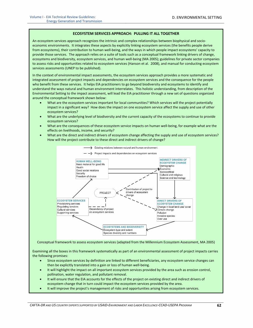
Volume I ‐ EIA Technical Review Guidelines: Energy Generation and Transmission
D. ENVIRONMENTAL SETTING
CAFTA‐DR AND US COUNTRY EXPERTS SUPPORTED BY USAID‐ENVIRONMENT AND LABOR EXCELLENCE‐CCAD‐USEPA PROGRAM 62
ECOSYSTEM SERVICES APPROACH: PULLING IT ALL TOGETHER
An ecosystem services approach recognizes the intrinsic and complex relationships between biophysical and socio‐economic environments. It integrates these aspects by explicitly linking ecosystem services (the benefits people derive from ecosystems), their contribution to human well‐being, and the ways in which people impact ecosystems’ capacity to provide those services. The approach relies on a suite of tools such as a conceptual framework linking drivers of change, ecosystems and biodiversity, ecosystem services, and human well‐being (MA 2005); guidelines for private sector companies to assess risks and opportunities related to ecosystem services (Hanson et al. 2008), and manual for conducting ecosystem services assessments (UNEP to be published).
In the context of environmental impact assessments, the ecosystem services approach provides a more systematic and integrated assessment of project impacts and dependencies on ecosystem services and the consequence for the people who benefit from these services. It helps EIA practitioners to go beyond biodiversity and ecosystems to identify and understand the ways natural and human environment interrelates. This holistic understanding, from description of the Environmental Setting to the impact assessment, will lead the EIA practitioner through a new set of questions organized around the conceptual framework shown below:
What are the ecosystem services important for local communities? Which services will the project potentially impact in a significant way? How does the impact on one ecosystem service affect the supply and use of other ecosystem services?
What are the underlying level of biodiversity and the current capacity of the ecosystems to continue to provide ecosystem services?
What are the consequences of these ecosystem service impacts on human well‐being, for example what are the effects on livelihoods, income, and security?
What are the direct and indirect drivers of ecosystem change affecting the supply and use of ecosystem services? How will the project contribute to these direct and indirect drivers of change?
Conceptual framework to assess ecosystem services (adapted from the Millennium Ecosystem Assessment, MA 2005)
Examining all the boxes in this framework systematically as part of an environmental assessment of project impacts carries the following promises:
Since ecosystem services by definition are linked to different beneficiaries, any ecosystem service changes can then be explicitly translated into a gain or loss of human well‐being.
It will highlight the impact on all important ecosystem services provided by the area such as erosion control, pollination, water regulation, and pollutant removal.
It will ensure that the EIA accounts for the effects of the project on existing direct and indirect drivers of ecosystem change that in turn could impact the ecosystem services provided by the area.
It will improve the project’s management of risks and opportunities arising from ecosystem services.
Volume I ‐ EIA Technical Review Guidelines: Energy Generation and Transmission
D. ENVIRONMENTAL SETTING
CAFTA‐DR AND US COUNTRY EXPERTS SUPPORTED BY USAID‐ENVIRONMENT AND LABOR EXCELLENCE‐CCAD‐USEPA PROGRAM 63
3.5 Protected Areas
Protected areas should be highlighted in the EIA as areas which have already been identified as significant and needing special protection. One of the challenges in preparing the EIA is the fact that boundaries of protected areas may be imprecise on available maps. Within the area of influence of the project, steps should be taken to better define these boundaries, to ensure that the proposed project will not encroach on the protected area. The Environmental Setting should also report on the status of management plans for the protected areas, and where applicable, identify the allowed uses in each management zone. The project should not be inconsistent with the allowable uses in a designated protected area. It is also important to identify areas in area of influence that are not currently designated as protected areas, but have been identified by governments or other stakeholders as having a high biodiversity conservation priority.
4 SOCIAL‐ECONOMIC‐CULTURAL ENVIRONMENT
4.1 Socio‐Economic Conditions
This subsection should include descriptive and quantitative information for the area surrounding the project site on:
Population, including age, gender, ethnic composition, religions, languages spoken and educational level
Economic activities, including industrial and commercial activities, employers, employment, incomes and distribution of income, tax base and skills, services and goods availability in the communities
Crime rates
Literacy rates
Community organizations
Public Health and Safety ○ Diseases in the project area (including the sources of data and the methodology used to
collect and analyze the data) ○ Existing practice for assessment of occupational health ○ Existing electromagnetic fields (primarily associated with high voltage electric power lines) ○ Local perceptions of the proposed project
4.2 Infrastructure
This subsection should include descriptive and quantitative information on the current and future planned infrastructure, in the absence of the proposed project, in the following areas:
Transportation
Public Health
Communications
Energy It should not repeat the information provided in the project and alternatives description (e.g., information on access roads that will be used) unless necessary for clarity.

Volume I ‐ EIA Technical Review Guidelines: Energy Generation and Transmission
D. ENVIRONMENTAL SETTING
CAFTA‐DR AND US COUNTRY EXPERTS SUPPORTED BY USAID‐ENVIRONMENT AND LABOR EXCELLENCE‐CCAD‐USEPA PROGRAM 64
4.2.1 Transportation
The information on the transportation infrastructure should addresses baseline conditions of transportation and traffic patterns on existing roads. This should include:
Maps showing the location of all existing roads, railroads, air strips, airports and pipelines
Condition ○ Surface materials ○ Erosion and sediment problems and controls ○ Maintenance programs (what, when and whom)
Description of anticipated third‐party improvements (government or entity other than the proponent)
Traffic patterns and densities on roads which may experience significant increased use during construction or operation of the project
Safety levels and current circulation issues, and capacity
4.2.2 Public Health
The information presented on the public health infrastructure includes information on the existing drinking water, wastewater and solid waste management systems. The Environmental Setting should provide maps and quantitative information on the existing infrastructure for these systems, their capacities and any plans for expansion or change in technology or management of the systems. For drinking water system(s), this should include:
Sources of drinking water,
Quality (before and after treatment)
Access
Trends in availability of potable water Information on the wastewater system(s) should be presented on maps as well as in narrative and tabular forms and include:
Quantity (inflow and discharges)
Treatment
Sludge disposal, if applicable
Discharge points
Trends Information on the solid waste management system(s) should include:
Quantity (daily quantities generated, collected and disposed of)
Collection systems
Recycling programs
Disposal facilities (locations, sizes and management)
4.2.3 Communications and Energy
Information on communications should include the types of communications systems in the project area and their associated infrastructure such as transmission lines and microwave towers. Information on energy should include the types and sources of energy in the project area including:
Generating facilities
Transmission and distribution lines
Storage facilities (including fuel storage facilities)
Volume I ‐ EIA Technical Review Guidelines: Energy Generation and Transmission
D. ENVIRONMENTAL SETTING
CAFTA‐DR AND US COUNTRY EXPERTS SUPPORTED BY USAID‐ENVIRONMENT AND LABOR EXCELLENCE‐CCAD‐USEPA PROGRAM 65
4.3 Cultural, Archeological, Ceremonial and Historic Resources
All cultural, archeological, ceremonial and historic resources within the project boundaries and within the area of direct impact should be inventoried and mapped. Excellent sources of information on location of such assets usually include federal ministries responsible for such assets, local religious institutions and scholars, and the UNESCO World Heritage Site (http://whc.unesco.org/en/list). During the preparation of the EIA, views should be solicited from stakeholders on whether the any sites or surrounding areas have important traditional or cultural value. This subsection should also include information on any indigenous people or other traditional cultures in the project area.
4.4 Land Use
The land use subsection of the Environmental Setting should include information on actual and potential land use in and around the proposed project. It should indicate trends in land use and patterns of land use. The information should be presented as a land use map showing location, size and proximity of:
Population centers
Agricultural lands
Forested lands
Flood plains and water bodies
Coastal zones
Protected areas
Wetlands
Other environmentally sensitive areas
Recreational or tourist areas
WHAT ARE WASTES AND WHAT TYPES OF WASTES SHOULD BE CONSIDERED? A waste is any solid, liquid, or contained gaseous material that is being discarded by disposal, recycling, burning, or incineration. It can be byproduct of a manufacturing process or an obsolete commercial product that can no longer be used for intended purpose and requires disposal. Solid (non‐hazardous) wastes generally include any garbage, refuse. Examples of such waste include domestic trash and garbage; inert construction / demolition materials; refuse, such as metal scrap and empty containers (except those previously used to contain hazardous materials which should, in principle, be managed as a hazardous waste); and residual waste from industrial operations, such as boiler slag, clinker, and fly ash. Hazardous waste shares the properties of a hazardous material (e.g. ignitability, corrosivity, reactivity, or toxicity), or other physical, chemical, or biological characteristics that may pose a potential risk to human health or the environment if improperly managed. Wastes may also be defined as “hazardous” by local regulations or international conventions, based on the origin of the waste and its inclusion on hazardous waste lists, or based on its characteristics. Sludge from a waste treatment plant, water supply treatment plant, or air pollution control facility, and other discarded material, including solid, liquid, semisolid, or contained gaseous material resulting from industrial operations should be evaluated on a case‐by‐case basis to establish whether it constitutes a hazardous or a non‐hazardous waste.

Volume I ‐ EIA Technical Review Guidelines: Energy Generation and Transmission
D. ENVIRONMENTAL SETTING
CAFTA‐DR AND US COUNTRY EXPERTS SUPPORTED BY USAID‐ENVIRONMENT AND LABOR EXCELLENCE‐CCAD‐USEPA PROGRAM 66
Culturally sensitive areas
Other land uses as appropriate The information on population centers should include information on the numbers, sizes and locations of:
Schools
Cemeteries
Churches
Other public buildings
Housing (including housing density) The information on the tourism and recreation areas should include the numbers, sizes and locations of recreation facilities and eco‐cultural‐tourist locations. This subsection should also include information on the current and projected future employment opportunities associated with tourism based on natural or cultural resources.
Volume I ‐ EIA Technical Review Guidelines: Energy Generation and Transmission
E. POTENTIAL IMPACTS
CAFTA‐DR AND US COUNTRY EXPERTS SUPPORTED BY USAID‐ENVIRONMENT AND LABOR EXCELLENCE‐CCAD‐USEPA PROGRAM 67
E. POTENTIAL IMPACTS
1 INTRODUCTION
The Impacts section of the EIA should identify and, to the extent possible, quantify the potential impacts of the project. This section of the Guidelines identifies the types of impacts that may be generally associated with power generation and transmission projects. Section F identifies predictive tools and methodologies that can be employed to present and quantify the impacts and the magnitude, duration and extent of those impacts and their significance. Energy projects can have impacts on physical, biological and social‐economic‐cultural resources in the construction, operation and closure stages of the project. The impact assessment should account for all of the activities involved in the project, including specific technologies. The EIA should define direct, indirect and cumulative impacts.
Direct impacts are due to a specific project‐related activity in the same place and time as the project.
Indirect impacts are due to actions resulting from the specific project, and are later in time or further removed in distance, but still are reasonably foreseeable. Indirect impacts may include growth inducing impacts and other impacts related to induced changes in the pattern of land use, population density, or growth rate, and related impacts on air and water and other natural systems, including ecosystems.
Cumulative impacts are the incremental impacts of the proposed project on a particular resource when added to past, present and reasonably foreseeable future actions, regardless of what entity undertakes such actions. Cumulative impacts can result from individually minor but collectively significant actions taking place over a period of time.
Impacts are site‐specific and are determined by the geology, soils, hydrology, hydrogeology, climate, ecosystems and human populations in the vicinity of the project. The impacts may be positive or negative. Positive impacts can result, for instance, if a new power plant is coupled with taking one or more older, more polluting power plants out of service, thus resulting in net improvement in environmental conditions.
Impacts associated with energy generation and transmission projects can vary considerably as the activities associated with individual projects can be quite different: from retrofitting a penstock with a water turbine at an existing dam, to building a new dam that will flood a large area, to installing a wind farm, to constructing a coal‐fired power plant. However, there are several activities that are common to nearly all projects such as land clearing and shaping, construction of facilities and support structures, and construction or upgrade of access roads and connections to the grid (short of building a new transmission line). In addition, many projects may involve construction and operation of temporary construction camps and onsite storage buildings, offices or housing. All of these activities and their associated impacts on the physical and biological environments are presented in Table E‐1. Table E‐1 is followed by subsections for each component of the physical and biological environments, in which the potential impacts to each component of each type of project are described. Each subsection begins by identifying and discussing the impacts common to most projects, followed by those specific to one or more (but not most) technologies. Table E‐2, located after the Biological Environment subsection,
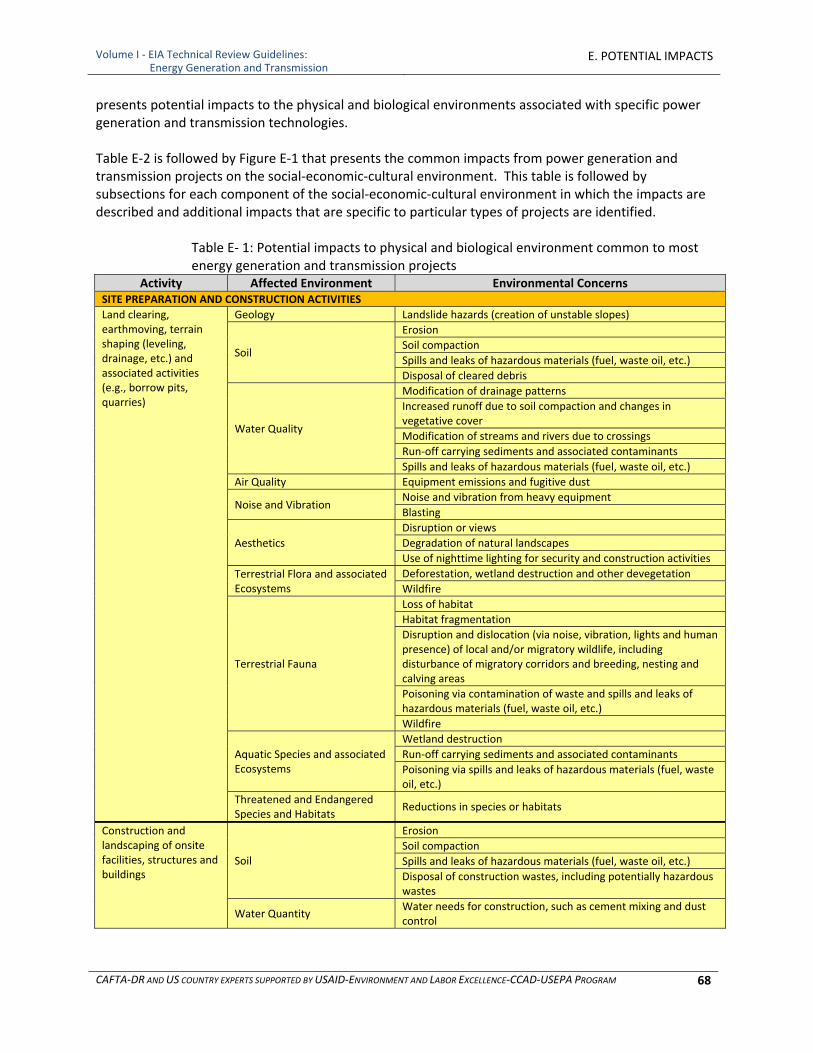
Volume I ‐ EIA Technical Review Guidelines: Energy Generation and Transmission
E. POTENTIAL IMPACTS
CAFTA‐DR AND US COUNTRY EXPERTS SUPPORTED BY USAID‐ENVIRONMENT AND LABOR EXCELLENCE‐CCAD‐USEPA PROGRAM 68
presents potential impacts to the physical and biological environments associated with specific power generation and transmission technologies. Table E‐2 is followed by Figure E‐1 that presents the common impacts from power generation and transmission projects on the social‐economic‐cultural environment. This table is followed by subsections for each component of the social‐economic‐cultural environment in which the impacts are described and additional impacts that are specific to particular types of projects are identified.
Table E‐ 1: Potential impacts to physical and biological environment common to most energy generation and transmission projects
Activity Affected Environment Environmental Concerns SITE PREPARATION AND CONSTRUCTION ACTIVITIES
Land clearing, earthmoving, terrain shaping (leveling, drainage, etc.) and associated activities (e.g., borrow pits, quarries)
Geology Landslide hazards (creation of unstable slopes)
Soil
Erosion
Soil compaction
Spills and leaks of hazardous materials (fuel, waste oil, etc.)
Disposal of cleared debris
Water Quality
Modification of drainage patterns
Increased runoff due to soil compaction and changes in vegetative cover
Modification of streams and rivers due to crossings
Run‐off carrying sediments and associated contaminants
Spills and leaks of hazardous materials (fuel, waste oil, etc.)
Air Quality Equipment emissions and fugitive dust
Noise and Vibration Noise and vibration from heavy equipment
Blasting
Aesthetics
Disruption or views
Degradation of natural landscapes
Use of nighttime lighting for security and construction activities
Terrestrial Flora and associated Ecosystems
Deforestation, wetland destruction and other devegetation
Wildfire
Terrestrial Fauna
Loss of habitat
Habitat fragmentation
Disruption and dislocation (via noise, vibration, lights and human presence) of local and/or migratory wildlife, including disturbance of migratory corridors and breeding, nesting and calving areas
Poisoning via contamination of waste and spills and leaks of hazardous materials (fuel, waste oil, etc.)
Wildfire
Aquatic Species and associated Ecosystems
Wetland destruction
Run‐off carrying sediments and associated contaminants
Poisoning via spills and leaks of hazardous materials (fuel, waste oil, etc.)
Threatened and Endangered Species and Habitats
Reductions in species or habitats
Construction and landscaping of onsite facilities, structures and buildings
Soil
Erosion
Soil compaction
Spills and leaks of hazardous materials (fuel, waste oil, etc.)
Disposal of construction wastes, including potentially hazardous wastes
Water Quantity Water needs for construction, such as cement mixing and dust control
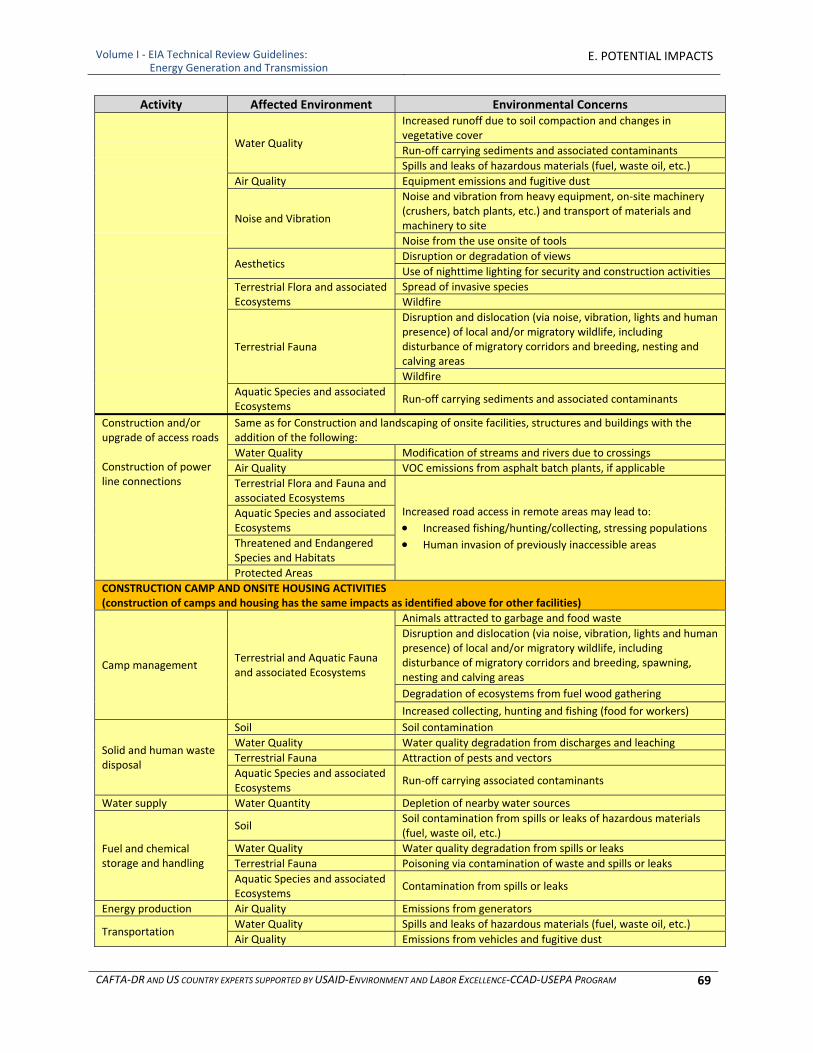
Volume I ‐ EIA Technical Review Guidelines: Energy Generation and Transmission
E. POTENTIAL IMPACTS
CAFTA‐DR AND US COUNTRY EXPERTS SUPPORTED BY USAID‐ENVIRONMENT AND LABOR EXCELLENCE‐CCAD‐USEPA PROGRAM 69
Activity Affected Environment Environmental Concerns
Water Quality
Increased runoff due to soil compaction and changes in vegetative cover
Run‐off carrying sediments and associated contaminants
Spills and leaks of hazardous materials (fuel, waste oil, etc.)
Air Quality Equipment emissions and fugitive dust
Noise and Vibration
Noise and vibration from heavy equipment, on‐site machinery (crushers, batch plants, etc.) and transport of materials and machinery to site
Noise from the use onsite of tools
Aesthetics Disruption or degradation of views
Use of nighttime lighting for security and construction activities
Terrestrial Flora and associated Ecosystems
Spread of invasive species
Wildfire
Terrestrial Fauna
Disruption and dislocation (via noise, vibration, lights and human presence) of local and/or migratory wildlife, including disturbance of migratory corridors and breeding, nesting and calving areas
Wildfire
Aquatic Species and associated Ecosystems
Run‐off carrying sediments and associated contaminants
Construction and/or upgrade of access roads Construction of power line connections
Same as for Construction and landscaping of onsite facilities, structures and buildings with the addition of the following:
Water Quality Modification of streams and rivers due to crossings
Air Quality VOC emissions from asphalt batch plants, if applicable
Terrestrial Flora and Fauna and associated Ecosystems
Increased road access in remote areas may lead to:
Increased fishing/hunting/collecting, stressing populations
Human invasion of previously inaccessible areas
Aquatic Species and associated Ecosystems
Threatened and Endangered Species and Habitats
Protected Areas
CONSTRUCTION CAMP AND ONSITE HOUSING ACTIVITIES (construction of camps and housing has the same impacts as identified above for other facilities)
Camp management Terrestrial and Aquatic Fauna and associated Ecosystems
Animals attracted to garbage and food waste
Disruption and dislocation (via noise, vibration, lights and human presence) of local and/or migratory wildlife, including disturbance of migratory corridors and breeding, spawning, nesting and calving areas
Degradation of ecosystems from fuel wood gathering
Increased collecting, hunting and fishing (food for workers)
Solid and human waste disposal
Soil Soil contamination
Water Quality Water quality degradation from discharges and leaching
Terrestrial Fauna Attraction of pests and vectors
Aquatic Species and associated Ecosystems
Run‐off carrying associated contaminants
Water supply Water Quantity Depletion of nearby water sources
Fuel and chemical storage and handling
Soil Soil contamination from spills or leaks of hazardous materials (fuel, waste oil, etc.)
Water Quality Water quality degradation from spills or leaks
Terrestrial Fauna Poisoning via contamination of waste and spills or leaks
Aquatic Species and associated Ecosystems
Contamination from spills or leaks
Energy production Air Quality Emissions from generators
Transportation Water Quality Spills and leaks of hazardous materials (fuel, waste oil, etc.)
Air Quality Emissions from vehicles and fugitive dust
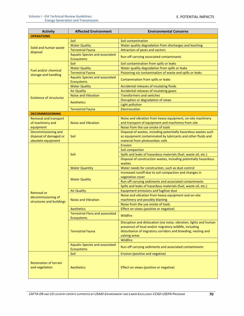
Volume I ‐ EIA Technical Review Guidelines: Energy Generation and Transmission
E. POTENTIAL IMPACTS
CAFTA‐DR AND US COUNTRY EXPERTS SUPPORTED BY USAID‐ENVIRONMENT AND LABOR EXCELLENCE‐CCAD‐USEPA PROGRAM 70
Activity Affected Environment Environmental Concerns OPERATIONS
Solid and human waste disposal
Soil Soil contamination
Water Quality Water quality degradation from discharges and leaching
Terrestrial Fauna Attraction of pests and vectors
Aquatic Species and associated Ecosystems
Run‐off carrying associated contaminants
Fuel and/or chemical storage and handling
Soil Soil contamination from spills or leaks
Water Quality Water quality degradation from spills or leaks
Terrestrial Fauna Poisoning via contamination of waste and spills or leaks
Aquatic Species and associated Ecosystems
Contamination from spills or leaks
Existence of structures
Water Quality Accidental releases of insulating fluids
Air Quality Accidental releases of insulating gases
Noise and Vibration Transformers and switches
Aesthetics Disruption or degradation of views
Light pollution
Terrestrial Fauna Electrocution
DECOMMISSIONING
Removal and transport of machinery and equipment
Noise and Vibration
Noise and vibration from heavy equipment, on‐site machinery and transport of equipment and machinery from site
Noise from the use onsite of tools
Decommissioning and disposal of damaged or obsolete equipment
Soil Disposal of wastes, including potentially hazardous wastes such as equipment contaminated by lubricants and other fluids and material from photovoltaic cells
Removal or decommissioning of structures and buildings
Soil
Erosion
Soil compaction
Spills and leaks of hazardous materials (fuel, waste oil, etc.)
Disposal of construction wastes, including potentially hazardous wastes
Water Quantity Water needs for construction, such as dust control
Water Quality
Increased runoff due to soil compaction and changes in vegetative cover
Run‐off carrying sediments and associated contaminants
Spills and leaks of hazardous materials (fuel, waste oil, etc.)
Air Quality Equipment emissions and fugitive dust
Noise and Vibration Noise and vibration from heavy equipment and on‐site machinery and possibly blasting
Noise from the use onsite of tools
Aesthetics Effect on views (positive or negative)
Terrestrial Flora and associated Ecosystems
Wildfire
Terrestrial Fauna
Disruption and dislocation (via noise, vibration, lights and human presence) of local and/or migratory wildlife, including disturbance of migratory corridors and breeding, nesting and calving areas
Wildfire
Aquatic Species and associated Ecosystems
Run‐off carrying sediments and associated contaminants
Restoration of terrain and vegetation
Soil Erosion (positive and negative)
Aesthetics Effect on views (positive or negative)
Volume I ‐ EIA Technical Review Guidelines: Energy Generation and Transmission
E. POTENTIAL IMPACTS
CAFTA‐DR AND US COUNTRY EXPERTS SUPPORTED BY USAID‐ENVIRONMENT AND LABOR EXCELLENCE‐CCAD‐USEPA PROGRAM 71
2 PHYSICAL ENVIRONMENT
2.1 Geology and Soils
Energy projects, with few exceptions (e.g., retrofitting an existing penstock with a water turbine), will include construction activities that can impact geology and soils including:
Land clearing for site preparation and access routes
Earth moving and terrain shaping including excavation and filling, involving earth moving equipment and often blasting
Disposal of spoils (vegetation, soil, stones) removed during these activities and construction debris
Use and possible storage of lubricants, fuels and other chemical products
Decommissioning Land clearing, earth moving and terrain shaping will remove vegetative cover and change the topography of the affected area, which can cause increased soil compaction, erosion and associated sedimentation. Changing the topography of the site can create the potential for landslides or slope failure, depending on the soil types and magnitude of the change. It will also change the drainage patterns and in combination with removal of vegetative cover can lead to erosion, the magnitude and extent of which will in part be determined by the resulting gradients, soil types, rainfall and local hydrology. Exposing bare soil during these activities can also increase wind erosion. These impacts can be short‐term, if proper soil erosion and slope stability controls are used or installed, although they may often exist through the completion of construction of onsite facilities, structures and buildings, access roads and transmission line connections, as these activities also disturb soil. The large amount of land required for utility‐scale solar power plants (approximately one square kilometer for every 20 to 60 MW generated) and hydroelectric projects that create new reservoirs makes this issue greater at these facilities than at other power generating facilities. Similarly, if construction of lengthy access roads is required by the project, this issue also will be of greater concern. Right‐of‐ways may cover a significant land mass, but seldom require land clearing, earth moving and terrain shaping. If, for a biomass or biofuel project, the source of production of biomass (i.e., the farms or forests that produce the raw materials) is included in the scope of the EIA, this may involve large areas of land and potential erosion impacts should be assessed. A potential effect of growing trees and other plants for energy is that it could benefit soil quality. Energy crops could be used to stabilize cropland or rangeland prone to erosion and flooding. Trees would be grown for several years before being harvested, and their roots and leaf litter could help stabilize the soil. The planting of coppicing, or self‐regenerating, varieties would minimize the need for disruptive tilling and planting. Perennial grasses harvested like hay could play a similar role. Soil losses with a crop such as switchgrass (Panicum virgatum), for example, would be negligible compared to annual crops such as corn. If improperly managed, however, energy farming could have harmful impacts on soils. Although energy crops could be grown with less pesticide and fertilizer than conventional food crops, large‐scale energy farming could nevertheless lead to increases in chemical use simply because more land would be under cultivation. If agricultural or forestry wastes and residues were used for fuel, then soils could be depleted of organic content and nutrients unless care is taken to leave enough wastes onsite to generate soil organic material.

Volume I ‐ EIA Technical Review Guidelines: Energy Generation and Transmission
E. POTENTIAL IMPACTS
CAFTA‐DR AND US COUNTRY EXPERTS SUPPORTED BY USAID‐ENVIRONMENT AND LABOR EXCELLENCE‐CCAD‐USEPA PROGRAM 72
Disposal of solid waste and spills of lubricants, fuels and chemicals (e.g., wood preservatives, herbicides) during land clearing, terrain shaping, construction (both onsite and offsite) and decommissioning and restoration creates the potential for soil and water contamination. The types of solid waste generated during these activities include:
Trees and other vegetation removed during site preparation
Casting forms
Defective or compromised building materials
Waste concrete
Waste from on‐site maintenance and repair of machinery and equipment
Waste from demolition of existing structures
Packaging, pallets and crates
Other wastes associated with onsite activities of workers in relation to the number of workers Solid waste disposal and chemical and fuel leaks and spills at construction camps and during all types of power plant facility operation can also contaminate soil. Camps and facilities can generate human wastes and solid wastes generated by the workers. Construction camps often include storage and dispensing facilities for fuels, lubricants and chemicals used during construction. Most power plants also have onsite facilities for storage of lubricants and other chemicals and hazardous materials used at the plant on a regular basis. During operation, and particularly during maintenance of machinery and equipment, the following solid and hazardous wastes may be generated:
Used oil
Contaminated absorbent materials
Burned out light bulbs
Used batteries
Toxic and hazardous substances and associated wastes
Hazardous and toxic substance containers
Tires
Used parts, scraps and debris Most power plants also have equipment onsite that contain hazardous substances, including insulating oils associated with transformers and switches. If these substances leak, they can contaminate soil. Insulating oils are used to cool transformers and switches and provide electrical insulation between live components. PCB’s were widely used as insulating oils on large equipment up until 2000, when their use was discontinued due to potential harmful effects on human health and the environment. Modern transformers and switches use the highly refined ASTM D3487 standard mineral oil. Insulating oils are typically found in the largest quantities at electrical substations and maintenance shops. In addition to these generic impacts associated with energy projects, there are specific impacts associated with specific types of projects. Several technologies generate unique solid wastes, the disposal of which can contaminate soil. These include:
Thermal/Combustion plants fueled by coal, oil, and biomass can generate: ○ Residues from onsite fuel washing or preparation
Volume I ‐ EIA Technical Review Guidelines: Energy Generation and Transmission
E. POTENTIAL IMPACTS
CAFTA‐DR AND US COUNTRY EXPERTS SUPPORTED BY USAID‐ENVIRONMENT AND LABOR EXCELLENCE‐CCAD‐USEPA PROGRAM 73
○ Ash and sludge resulting from combustion and collected by pollution control devices, which may contain mercury, selenium, arsenic or other metals, depending on fuel analysis
All types of Thermal plants requiring cooling systems can generate solid wastes removed from the system. These wastes may be may be partially dehydrated or dried before disposal and include: ○ Cooling water sludge ○ Materials dredged cooling ponds and associated structures ○ Materials removed from cooling towers
Hydroelectric plants with reservoirs can generate solid wastes from dredged from the reservoir, or anywhere else where unwanted sediments may accumulate.
Solar Dish‐Engine and many Thermal Solar and Geothermal plants will use and store heat transfer fluids.
Solar Photovoltaic plants can produce hazardous waste related to the decommissioning of solar photovoltaic cells. These cells may contain components made of hazardous materials.
Open‐Loop Geothermal projects can also produce sludge deposited by geothermal water throughout the system that needs to be periodically collected and disposed of.
Coal‐fired and biomass‐fired (including solid waste) thermal power plants generate the greatest amount of solid wastes due to the relatively high percentage of ash in the fuel. Coal combustion wastes include fly ash, bottom ash, boiler slag, and bed ash (the combination of fly ash and bottom ash generated in a fluidized‐bed combustion boiler). Coal‐fired plants can also generate flue gas desulfurization (FGD) sludge. Biomass contains less sulfur; therefore FGD may not be necessary. Fly ash removed from exhaust gases makes up 60 to 85 percent of the coal ash residue in pulverized‐coal boilers and 20 percent in stoker boilers. Bottom ash includes slag and particles that are coarser and heavier than fly ash. Due to the presence of sorbent material, fluidized‐bed combustion boiler wastes have a higher content of calcium and sulfate and a lower content of silica and alumina than conventional coal combustion wastes. Metals are constituents of concern in both coal combustion wastes and low‐volume solid wastes. For example, ash residues and the dust removed from exhaust gases may contain significant levels of heavy metals and some organic compounds, in addition to inert materials. Ash residues are not typically classified as a hazardous waste due to their inert nature. However, where ash residues are expected to contain potentially significant levels of heavy metals, radioactivity, or other potentially hazardous materials, they should be tested at the start of plant operations to verify their classification as hazardous or non‐hazardous according to local regulations or internationally recognized standards. Oil combustion wastes include fly ash and bottom ash and are normally only generated in significant quantities when residual fuel oil is burned in oil‐fired steam electric boilers. Other thermal/combustion technologies (e.g., combustion turbines and diesel engines) and fuels (petroleum and diesel) generate little or no solid wastes. Gas‐fired thermal power plants generate essentially no solid waste because of the negligible ash content, regardless of the combustion technology. Geothermal technologies generally do not produce a substantial amount of solid waste, but open‐loop systems can generate large amounts of solid wastes as sulfur, silica, and carbonate precipitates in cooling towers, air scrubber systems, turbines, and steam separators. This sludge may be classified as
Volume I ‐ EIA Technical Review Guidelines: Energy Generation and Transmission
E. POTENTIAL IMPACTS
CAFTA‐DR AND US COUNTRY EXPERTS SUPPORTED BY USAID‐ENVIRONMENT AND LABOR EXCELLENCE‐CCAD‐USEPA PROGRAM 74
hazardous depending on the concentration and potential for leaching of silica compounds, chlorides, arsenic, mercury, vanadium, nickel, and other heavy metals. These wastes may be dried and disposed of in landfills meeting hazardous waste requirements in which case they can impact have the potential to impact soil quality at the disposal as well as the potential for impacting soil quality during transport from the points of generation and treatment to the point of disposal The disposal of solid wastes is not the only activity at power generation and transmission projects that can contaminate soil:
Thermal/Combustion plants produce air emissions which can be deposited on soil downwind from the facility resulting in soil contamination
Thermal/Combustion plants fueled by oil and petroleum can store large volumes of fuel onsite, creating the potential for leaks and spills that can contaminate soil
Biomass projects can have impacts on soils on the farms or forests at which the biomass is produced, including potential salinization if the farms are irrigated and potential soil contamination if pesticides and fertilizers are improperly managed
Similar soil contamination impacts can be associated with Transmission Line projects, if herbicides are proposed for vegetative management and they are not managed correctly
Finally, some types of projects can have impacts associated with geologic resources.
All projects that involve building dams, either for hydroelectric reservoirs or cooling water ponds are subject to possible dam failures as a result of seismic activities
Withdrawal of geothermal water can cause land subsidence in land overlying the aquifers from which the water is withdrawn. If, however, the spent water is reinjected into the aquifer, subsidence may be avoided.
Enhanced geothermal system activities such as from reservoir stimulation, are a potential concern to local residents, including a concern that activities may induce earthquakes. Reports of small tremors at or near geothermal fields in the United States generally have indicated minimal or no harm, however there have been some reports of building shaking and cracked foundations. Reports of a small (magnitude 3.4) but damaging earthquake triggered by an enhanced geothermal project in Basel, Switzerland have raised concerns about potential for induced seismicity at projects in California. The U.S. Department of Energy is developing a protocol to ensure that seismicity risks are low from geothermal projects.
2.2 Water Resources
As discussed in the previous subsection on Geology and Soil, nearly all energy projects involve land clearing for site preparation and access routes and earth moving and terrain shaping, which may change the drainage patterns and increase runoff and associate soil erosion and sedimentation. For power plants fueled by biomass, if the source of production of biomass (i.e., the farms or forests that produce the raw materials) is included in the scope of the EIA, then runoff and erosion from those lands are also an issue to be addressed in the EIA. Runoff can carry sediments and other contaminants either attached to the sediment or in solution, including soil nutrients and lubricants, fuels and chemicals that may be spilled at the sites. Any source of soil contamination identified in the previous subsection, can be carried in runoff. If agricultural chemicals are used on farms or forests associated with biomass production or if herbicides are used
Volume I ‐ EIA Technical Review Guidelines: Energy Generation and Transmission
E. POTENTIAL IMPACTS
CAFTA‐DR AND US COUNTRY EXPERTS SUPPORTED BY USAID‐ENVIRONMENT AND LABOR EXCELLENCE‐CCAD‐USEPA PROGRAM 75
during land clearing or to manage vegetation in right‐of‐ways, they can also become components of runoff. Depending on the local conditions and the distance to surface water, these contaminants can impact water quality in the surface waters that receive drainage from the affected areas. Construction or upgrading of access roads to the facility site or to the right‐of‐way, in the case of transmission projects, may also require construction across wetlands or streams, which can disrupt watercourses and wetland flow regimes, directly impact water quality and cause bank erosion. Another potential water quality impact can occur when power transmission cables are installed on marine floors. This is done with a cable‐laying vessel and a remotely operated, underwater vehicle. The cable laying operation can cause sedimentation resulting in turbidity and reductions in water quality. As identified in the previous subsection, Geology and Soils, power production facilities generate various types of process solid wastes that have the potential to contaminate soil. These same solid wastes can also contaminate surface water and groundwater quality. If runoff is allowed to flow off of areas where these wastes are stored or disposed, they have the potential of contaminating surface water. If rain fall is retained on the storage or disposal areas, and the sites are not lined then the solid wastes have the potential to contaminate groundwater via leachate. All power plants may need domestic water and may produce domestic solid wastes and domestic wastewater due to the onsite presence of workers. The amount of water required for domestic purposes and the amount of waste generated will generally be minimal, but the EIA should assess the impacts of these activities to ensure that they will not impact water availability or contaminate surface or groundwater. All power plants except wind need water for operation. Solar plants require water for washing reflector and glass surfaces. These withdrawals could have an impact on water availability, and should be assessed. The amount of water is not great (62 m3/year/MW), but its potential impact on water availability in the area of influence should be assessed, particularly if the plant is located in an area with a water shortage. The water is used in open areas and generally excess water enters the soil where it is evaporated or transpired by vegetation, generally not causing water quality impacts. Thermal/Combustion, Solar Thermal and Geothermal plants, require water for cooling, boiler makeup (open‐loop geothermal plants being an exception), auxiliary station equipment and, at coal‐ or biomass‐fired plants, ash handling and FGD systems. During construction water will be required to pressure check tanks and flush piping and tubing. They can use significant quantities of water for these purposes, which may have big impact on water availability. Thermal power plants use steam turbines with boilers and/or heat recovery steam generators used in combined cycle gas turbine units. All require a cooling system to condense steam used to generate electricity. Typical cooling systems used in thermal power plants include:
Once‐through cooling system where sufficient cooling water and receiving surface water are available
Closed circuit wet cooling system
Closed circuit dry cooling system (e.g., air cooled condensers) Wet cooling systems are the most common systems used in thermal power plant.
Volume I ‐ EIA Technical Review Guidelines: Energy Generation and Transmission
E. POTENTIAL IMPACTS
CAFTA‐DR AND US COUNTRY EXPERTS SUPPORTED BY USAID‐ENVIRONMENT AND LABOR EXCELLENCE‐CCAD‐USEPA PROGRAM 76
Once‐through cooling systems require large quantities of water to cool and condense the steam for return to the boiler. This cooling water is discharged back to receiving surface water or into cooling ponds. It will have elevated temperature and can carry biocides or other additives, if they are used, but otherwise can have little difference in composition than the source of the water. If the water is cooled (via a cooling pond for instance) and reused, the natural chemical components in the source water as well as any additives can become concentrated due to evaporation. Cooling water discharges are not the only wastewater streams in thermal power plants. Other wastewater streams include:
Cooling tower blow‐down
Ash handling wastewater
Wet FGD system discharges
Material storage runoff (for coal‐ and biomass‐fired plants)
Cleaning wastewater
Low‐volume wastewater, such as ○ Air heater and precipitator wash water ○ Boiler blow‐down ○ Boiler chemical cleaning waste ○ Floor and yard drains and sumps ○ Laboratory wastes ○ Back‐flush from ion exchange boiler water purification units ○ Domestic wastewater
Contaminants from these wastewater streams can degrade water quality via discharge to surface water or recharge to groundwater. The characteristics of the wastewaters generated depend on the ways in which the water has been used. Contamination arises from the use of demineralizers; lubricating and auxiliary fuel oils; trace contaminants in the fuel (introduced through the ash‐handling wastewater and wet FGD system discharges); and chlorine, biocides, and other chemicals used to manage the quality of water in cooling systems. Cooling tower blow‐down tends to be very high in total dissolved solids but is generally classified as non‐contact cooling water and, as such, is typically subject to limits for pH, residual chlorine, and toxic chemicals that may be present in cooling tower additives (including corrosion inhibiting chemicals containing chromium and zinc whose use should be eliminated). Each wastewater stream should be identified and fully characterized in regards to volume and composition, to determine if it will pose a threat to water quality. Characterization is discussed in section F, Assessing Impacts. Geothermal plants have some potential water quality and quantity impacts unique to them. The extraction, reinjection, and discharge of geothermal fluids may affect the quality and quantity of surface and groundwater resources. Examples of specific impacts include the inadvertent introduction of drilling mud and geothermal fluids into shallower productive aquifers during extraction and reinjection activities or a reduction in the flow of hot thermal springs due to withdrawal activities. Although very rare, well blowouts and pipeline failures may occur during well drilling or facility operations. Such failures can result in the release of toxic drilling additives and fluids, as well as geothermal fluids into overlying aquifers. Pipeline ruptures may also result in the surface release of geothermal fluids and steam. These fluids and steam can contain heavy metals, acids, mineral deposits and other pollutants.
Volume I ‐ EIA Technical Review Guidelines: Energy Generation and Transmission
E. POTENTIAL IMPACTS
CAFTA‐DR AND US COUNTRY EXPERTS SUPPORTED BY USAID‐ENVIRONMENT AND LABOR EXCELLENCE‐CCAD‐USEPA PROGRAM 77
Steam production and re‐injection wells may be installed during exploration, development, and operational activities. Drilling fluids employed during drilling activities may be water‐ or oil‐based, and may contain chemical additives to assist in controlling pressure differentials in the drill hole and to act against viscosity breakdown. Cuttings from oil‐based mud are of particular concern due to the content of oil‐related contaminants and may necessitate special on‐site or off‐site treatment and disposal. Spent geothermal fluids consist of the reject water from steam separators (rejected water is water that initially accompanies the steam from the geothermal reservoir), and condensate derived from spent steam condensation following power generation (open‐loop systems). Facilities that use water cooling towers in an evaporative process typically direct geothermal condensate into the cooling cycle. Geothermal condensate may be characterized by high temperature, low pH, and heavy metals content. Reject waters from the separators are often pH neutral and may contain heavy metals. Formation steam and water quality varies depending on the characteristics of the geothermal resource. Closed‐loop systems are almost totally benign, since gases and fluids removed from the well are not exposed to the atmosphere and are usually injected back into the ground after giving up their heat. Nonetheless, there is the potential for groundwater contamination during reinjection, if it is not properly designed and maintained. Any projects that include the use of dams, such as those needed for Hydroelectric reservoirs or Thermal power cooling dams can have their own unique potential impacts on water quantity and quality. The impoundments behind the dam can impact water table levels in their vicinity. This can cause seepage downstream of the dam and impact nearby wells and springs as well as surface water flows. Depending on the quality of the water in the impoundments, they can also have an impact on groundwater quality. If the impacted aquifer discharges to springs and surface waters, surface water quality can also be impacted. Dams are subject to containment failure and overflows, which can impact downstream flows and, in the case of cooling ponds, release contaminated water. Hydroelectric projects may affect the quantity and quality of water in the project area. Projects with in‐stream diversions and/or dams can alter flow in a water course. Diversions, whether temporary during dam construction or permanent for hydroelectric generation, can drastically change water flow in stream beds between the diversion and discharge points. During the filling of an impoundment behind a dam, downstream flow can be drastically reduced. The management of dam releases (generally based on demand for energy production) directly influences downstream flows. Projects using instream energy generation technologies without dams or diversions are likely to have minimal to no adverse environmental impacts to water resources, considering both operations and the low level of construction required to develop the projects. In‐stream dams also hold back sediments that can change downstream water quality and can cause downstream bank and streambed erosion. Retaining sediment can improve downstream turbidity, but when a river is deprived of its sediment load, it seeks to recapture it by eroding the downstream riverbed and banks. Riverbeds downstream of dams are typically eroded by several meters within the first decade after dam construction. The damage can extend for tens or even hundreds of kilometers below a dam. Riverbed deepening from scouring caused by reduction in sediments can also lower water tables along a river, if the river is hydraulically connected to the surrounding groundwater, thus reducing water availability in wells and springs. Other water quality issues potentially associated with reservoirs include:
Volume I ‐ EIA Technical Review Guidelines: Energy Generation and Transmission
E. POTENTIAL IMPACTS
CAFTA‐DR AND US COUNTRY EXPERTS SUPPORTED BY USAID‐ENVIRONMENT AND LABOR EXCELLENCE‐CCAD‐USEPA PROGRAM 78
Accumulation of nutrients leading to increased growth in microbacteria, aquatic plants, etc. and potentially leading to eutrophication and reductions in dissolved oxygen
Temperature stratification and associated impacts on dissolved oxygen and chemical composition
Discharge of oxygen depleted water due to the fact that the discharge water usually comes from several meters below the surface of the reservoir where oxygen levels are lower (Oxygen levels can rise rapidly after the point of discharge if there is turbulent flow.)
2.3 Air Resources
Air contamination at energy generation and transmission projects arise primarily from dust and equipment emissions during construction and decommissioning and from stack emissions at thermal/combustion power plants during operation. Dust is generated at all energy projects during land clearing, earth moving, terrain shaping, construction and decommissioning activities. Despite the best attempts to control dust, there can be areas and times when elevated dust concentrations can occur during these activities. A large portion of dust is made up of large particles, with diameters greater than 10 microns. This coarse dust usually settles gravitationally within a few hundred meters of the source. The smaller particle size fractions (PM10), however, can be carried by wind in dust clouds for great distances and may be deposited on or near populated areas. Dust from land clearing and construction, however, is a short‐term impact. At coal‐ and biomass‐fired power plants, fugitive dust can also be released during transportation, unloading, storage and processing of fuels. During site preparation and construction, the project will likely generate particulate and gaseous air pollutant emissions from vehicle and construction equipment exhaust. Particulate emissions (including PM10 emissions), carbon monoxide, unburned hydrocarbons (volatile organic compounds), nitrogen oxides and sulfur dioxide result from fuel combustion in vehicles, heavy equipment, and generators associated with land clearing and construction. If asphalt batch plants will be used during these activities, then there can also be emissions of volatile organic compounds (VOCs). Many power generation and transmission projects include substations with electrical transformers and switches. Some transformers, switches, associated cables and tubular transmission lines contain insulating gases such as fluorocarbons and sulfur hexafluoride (SF6). These are all greenhouse gases. SF6 is a greenhouse gas with a significantly higher global warming potential than carbon dioxide (CO2). Some solar dish‐engines use hydrogen or helium as a working gas. At those facilities, not only will the gas be in the engines, but the facility will likely keep a supply on site for maintenance and repair. In both the situations, there is the possibility of releases of these gases if the equipment is damaged. During operation, the greatest air emissions will be associated with power plants fueled by fossil fuels, biomass and biofuel. The primary emissions from the combustion of fossil fuels and biomass are nitrogen oxides (NOX), particulate matter (PM), carbon monoxide (CO) and greenhouse gases, such as CO2. Fossil fuel facilities fueled by oil and coal will also emit sulfur dioxide (SO2). In addition, fossil fuel plants that burn waste fuels or solid fuels as well as biomass‐fired plants that burn solid wastes can release heavy metals (i.e., mercury, arsenic, cadmium, vanadium, nickel, etc), halide compounds (including hydrogen fluoride), unburned hydrocarbons and other VOCs. These latter pollutants may be
Volume I ‐ EIA Technical Review Guidelines: Energy Generation and Transmission
E. POTENTIAL IMPACTS
CAFTA‐DR AND US COUNTRY EXPERTS SUPPORTED BY USAID‐ENVIRONMENT AND LABOR EXCELLENCE‐CCAD‐USEPA PROGRAM 79
emitted in smaller quantities, but may have a significant influence on the environment due to their toxicity and/or persistence. The amount and nature of air emissions depends on factors such as type of fuel (e.g., coal, fuel oil, natural gas, or biomass), the type and design of the combustion unit (e.g., reciprocating engines, combustion turbines, or boilers), operating practices, emission control measures (e.g., primary combustion control, secondary flue gas treatment), and the overall system efficiency. For example, gas‐fired plants generally produce negligible quantities of particulate matter and sulfur oxides, and levels of nitrogen oxides are about 60 percent of those from plants using coal (without emission reduction measures). Natural gas‐fired plants also release lower quantities of carbon dioxide, a greenhouse gas. Geothermal power plant emissions typically are negligible compared to those of combustion‐based power plants. Hydrogen sulfide (H2S) and mercury are the main potential air pollutants associated with geothermal power generation. Their release is an issue for open‐loop systems employing flash or dry steam technologies. Also, although very rare, well blowouts and pipeline failures may occur during well drilling or facility operations resulting in releases of gases from underground formations. While air quality impacts from geothermal facilities are generally small, public and regulatory concerns have sometimes been high. This is primarily due to the fact that the major pollutant, H2S, has an extremely low olfactory threshold, causing odor problems for nearby residents. In addition, the presence of toxic pollutants such as mercury, radon, and arsenic in some geothermal areas has raised concerns. Several greenhouse gases are associated with power generation and transmission, including CO2, N2O, methane (CH4), hydrofluorocarbons, perfluorocarbons, and SF6. CO2, one of the major greenhouse gases under the United Nations Framework Convention on Climate Change, and N2O are emitted from the combustion of fossil fuels, biomass and biofuel. Methane can be released at geothermal facilities during drilling and during the operation of open‐loop system. It can be released at gas‐fired power plants from leaks in pipelines, compressors and valves. Methane can also be released during the anaerobic digestion of organic wastes at biofuel plants or in organic sediments associated with dams. As mentioned previously, fluorocarbons, and SF6 may be used as insulating gases in high voltage power transformers, switches and transmission systems. Among the types of facilities and activities covered by these guidelines, the greatest emitters of green house gases are thermal/combustion power plants fueled by fossil fuel or biomass. Geothermal plants have the potential to release CO2 associated with geothermal water and steam, but a geothermal plant still only releases about five percent of the amount of CO2 emitted by a coal or oil‐fired power plant (as measured as CO2 per kilowatt‐hour of electricity generated). Substituting biomass for fossil fuels can, if done in a sustainable fashion, greatly reduce emissions of greenhouses gases. The amount of carbon dioxide released when biomass is burned is very nearly the same as the amount required to replenish the plants grown to produce the biomass. Thus, in a sustainable fuel cycle, there would be no net emissions of carbon dioxide, although some fossil‐fuel inputs may be required for planting, harvesting, transporting, and processing biomass. Yet, if efficient cultivation and conversion processes are used, the resulting emissions should be small (around 20 percent of the emissions created by fossil fuels alone). And if the energy needed to produce and process biomass came from renewable sources, the net contribution to global warming would be zero. Similarly, if biomass wastes such as crop residues or municipal solid wastes are used for energy, there
Volume I ‐ EIA Technical Review Guidelines: Energy Generation and Transmission
E. POTENTIAL IMPACTS
CAFTA‐DR AND US COUNTRY EXPERTS SUPPORTED BY USAID‐ENVIRONMENT AND LABOR EXCELLENCE‐CCAD‐USEPA PROGRAM 80
should be few or no net greenhouse gas emissions. There would even be a slight greenhouse benefit in some cases, since, when landfill wastes are not burned, the potent greenhouse gas methane may be released by anaerobic decay. It is important to note that there is considerable technical controversy regarding the net life‐cycle greenhouse gas emissions associated with producing energy or fuels from biomass, particularly where land use change (e.g., rain forest‐to‐cropland) may occur. Some researchers dispute the greenhouse gas benefits of biomass use, citing, among other things, a need to account for energy use in producing biomass, potential N2O emissions associated with fertilizer use, indirect land use changes at other locations resulting from changes in land use to produce biomass, foregone sequestration, and a need to repay a “carbon debt” resulting from the release of carbon from disturbed soil systems. Despite some important disagreement, the prevailing view is that biomass to energy applications can provide greenhouse gas benefits, and that, while the appropriate quantification of indirect greenhouse gas emissions is being debated, sustainable policies could play an important role in ensuring that biomass use provides environmental benefits.
2.4 Noise and Vibration
Noise and vibration at energy generation and transmission projects are generated during construction and decommissioning activities from blasting, construction equipment, and the transport of equipment and materials. Nearly all energy projects have associated transformers and switches, which are a source of noise. Other operational noises at energy power plants vary with the type of plant. Noise and vibration from wind turbines can be significant, whereas solar photovoltaic plants will generate virtually no noise. Solar dish‐engines will generally have noise levels below those of internal combustion engines. Stirling engines, which are commonly used at these facilities, are known for being quiet, relative to internal combustion gasoline and diesel engines. Even the highly recuperated Brayton engines are reported to be relatively quiet. The biggest source of noise from a Stirling engine system is the cooling fan for the radiator. Principal sources of noise in thermal power plants include the turbine generators and auxiliaries; boilers and auxiliaries; fans and ductwork; pumps; compressors; condensers; precipitators, including rappers and plate vibrators; piping and valves; reciprocating engines; motors; radiators; and cooling towers. At coal‐ and biomass‐fired thermal plants the transportation of fuel via trucks or trains and its preparation (e.g., pulverizers, choppers) are also sources of noise. Thermal power plants used for base load operation may operate continually while smaller plants may operate less frequently but still pose a significant source of noise if located in urban areas. Additional noise sources in geothermal facilities are related to well drilling, steam flashing and venting. Temporary noise levels may exceed 100 A‐weighted decibels (dBA, a scale which simulates the sensitivity of the human ear) during certain drilling and steam venting activities. At hydroelectric plants, the principal sources of noise are turbines, generators, compressors, ventilation systems and spillway discharges.
Volume I ‐ EIA Technical Review Guidelines: Energy Generation and Transmission
E. POTENTIAL IMPACTS
CAFTA‐DR AND US COUNTRY EXPERTS SUPPORTED BY USAID‐ENVIRONMENT AND LABOR EXCELLENCE‐CCAD‐USEPA PROGRAM 81
2.5 Aesthetic Resources
Impacts of power generation and transmission projects on landscape and aesthetic resources include:
Impacts on visual resources and landscapes
Impacts on visibility (air contamination projects only)
Increases in light contamination Visual impacts of power projects and transmission lines are highly variable, depending on the project type, location, lines of sight, and scenic vistas that may exist in the project area. Visual impacts may include power plants, smoke stacks, cooling towers, dams, wind turbines, arrays of solar collectors, roads, and right‐of‐ways. Light pollution is excessive or obtrusive artificial light and can be a problem at all power generating projects and at substations associated with transmission projects. Light pollution is a broad term that refers to multiple problems, all of which are caused by inefficient, unappealing, or (arguably) unnecessary use of artificial light. Light pollution sources from power projects include:
Lights used during construction to enable work at night or during low light conditions
Building and structure exterior and interior lighting
Nighttime security lighting
On‐site streetlights
Vehicular lighting associated with traffic to and from the site
Glare from solar panels Thermal/combustion power plants can degrade ability to view vistas from a distance due to air emissions generated from combustion.
3 BIOLOGICAL ENVIRONMENT
The primary pathways of impacts on the biological environment are contamination of soil, water and air and alteration of flow in surface water. However, biological resources can also be affected by land use conversions, increased human activity in the vicinity of the project, and increased pressure on natural resources in the area of influence due to human population increases associated with the project.
3.1 Flora, Fauna and Ecosystems
3.1.1 Terrestrial Species and Associated Ecosystems
Terrestrial species are those which may occur on land, including mammals, birds, reptiles, amphibians, invertebrates, trees, shrubs, forbs, grasses, fungi, mosses and microbes. Possible impacts on terrestrial species and the ecosystems associated with them (including wetlands and riparian areas) include:
Destruction, modification or fragmentation of habitat
Disruption of behavior, including feeding, migration, breeding, nesting, and calving
Direct impacts ○ Poisoning from direct contact with hazardous substances or contamination of watering
holes ○ Electrocution or incineration ○ Impacts with wind turbine blades ○ Increased collection and hunting

Volume I ‐ EIA Technical Review Guidelines: Energy Generation and Transmission
E. POTENTIAL IMPACTS
CAFTA‐DR AND US COUNTRY EXPERTS SUPPORTED BY USAID‐ENVIRONMENT AND LABOR EXCELLENCE‐CCAD‐USEPA PROGRAM 82
Destruction or fragmentation of terrestrial ecosystems is largely associated with land clearing, earthmoving and terrain shaping at the facility site and along access roads and right‐of‐ways. However, the creation of water impoundments can also flood ecosystems. This may be a relatively small area in the case of cooling ponds, or several hundreds of hectares in the case of a large hydroelectric dam. Excessive collection of fuel wood by workers during construction or operation can also lead to deforestation. Destruction of ecosystems can also be caused indirectly if emissions from a thermal/combustion plant kill or reduce productivity of vegetation downwind from the facility. For biomass projects that propose burning wood, the associated increase in the amount of forest wood harvested could have both positive and negative effects. On one hand, it could provide an incentive for the forest‐products industry to manage its resources more efficiently, and thus improve forest health. But it could also provide an excuse, under the "green" mantle, to exploit forests in an unsustainable fashion, resulting in the destruction of species habitat. Unfortunately, commercial forests have not always been soundly managed, and many people view with alarm the prospect of increased wood cutting. Wildfire is another source of ecosystem destruction. Facility construction and operation increases the number of humans in its vicinity, which increases the possibility of human caused wildfires. This is also true along access routes and right‐of‐ways. If vegetative management of right‐of‐ways allow for the build‐up of fire fuels, such as slash, this can increase the intensity of fires in the right‐of‐ways. Hydroelectric dams can cause seepage below the dam, which can impact terrestrial ecosystems where the seepage occurs. Riverbed scouring caused by hydroelectric dams can cause stream bed erosion, which can lower water availability in riparian zones in the area of the scouring, causing die‐off of vegetation. The construction of access roads and right‐of‐ways can fragment existing ecosystems and interrupt migratory corridors. Access roads and right‐of‐ways can also open to human activities areas that had previously been relatively wild, disturbing the species in those areas and creating opportunities for increased collection or harvest of plant life and collection or hunting of animals. Some ecosystems are more critical to species survival than others. These include migratory routes or corridors, watering holes, salt licks, and breeding, nesting and calving areas. These areas should have been identified in the preparation of the Environmental Setting. Any impacts in these areas should receive special attention. Modification of habitat can be associated with right‐of‐way management as well as with releases of noxious or invasive species. Excessive vegetation maintenance in right‐of‐ways may remove unnecessary amounts of vegetation resulting in disrupting succession and increasing the likelihood of the establishment of non‐native invasive species. Alteration of terrestrial habitat for construction of transmission and distribution projects may also yield benefits for wildlife such as the creation of protective nesting, rearing, and foraging habitat for certain species; the establishment of travel and foraging corridors for ungulates and other large mammals; and nesting and perching opportunities for large bird species atop transmission towers and associated infrastructures.

Volume I ‐ EIA Technical Review Guidelines: Energy Generation and Transmission
E. POTENTIAL IMPACTS
CAFTA‐DR AND US COUNTRY EXPERTS SUPPORTED BY USAID‐ENVIRONMENT AND LABOR EXCELLENCE‐CCAD‐USEPA PROGRAM 83
Energy generation and transmission projects can disrupt animal behavior in several ways. If the project involves a construction camp or onsite housing during operation, animals can be attracted to garbage and food waste thus changing there feeding habits and their interactions with humans. Regular maintenance of right‐of‐ways to control vegetation may involve the use of mechanical methods, such as mowing or pruning machinery, in addition to manual hand clearing and herbicide use, all of which can disrupt wildlife and their habitats. Noise, vibration, illumination, and vehicular movement can disrupt animal activities. These are particularly of concern if animals are disrupted in sensitive habitats, such as migratory routes or corridors, watering holes, salt licks, and breeding, nesting and calving areas. Light pollution can pose a serious threat to wildlife, having negative impacts on plant and animal physiology. Light pollution can confuse animal navigation, alter competitive interactions, change predator‐prey relations, and cause physiological harm. The rhythm of life is orchestrated by the natural diurnal patterns of light and dark, so disruption to these patterns impacts the ecological dynamics. Direct impacts to wildlife can be caused by increase hunting, improper solid or liquid waste disposal and direct contact by animals with project components. Increased collection and hunting can be stimulated by increased human activity in the area by workers and the population that grows to meet those workers needs. Improper waste disposal can bring animals into direct contact with hazardous substances or poison watering holes. The most common form of animal contact is electrocution via contact with equipment in substations, but other types of negative contacts can also occur including avian collisions with solar heliostat towers and potential for bird incineration and blinding from solar technology. The combination of the height of transmission towers and the electricity carried by transmission lines can pose potentially fatal hazard to birds and bats through collisions and electrocutions. Avian collisions with power lines can occur in large numbers if located within daily flyways or migration corridors, or if groups are traveling at night or during low light conditions (e.g., dense fog). In addition, bird and bat collisions with power lines may result in power outages and fires. Birds and bats also may be directly impacted by wind turbines. Many factors affect the potential risk of harm to birds and bats from wind turbines, including turbine variables (size, rotational speed, operational time, rotor swept area, spacing, tower type), variables at the turbine site (habitat, presence of features such as caves or cliffs) and bird/bat behavior (seasonal migration, hunting or feeding behaviors, other species‐specific behaviors). Loss of bat populations can have significant secondary impacts on both agriculture and public health because of the role bats play in controlling insect populations. Morbidity and mortality of birds as a result of wind turbine operation is caused by blade impact – typically at or near the tip of the blade where radial velocities are high. Morbidity and mortality among bats is largely caused by barotraumas – a sudden reduction in barometric pressure near the blade. Research indicates that operational adjustments, such as altering wind turbine cut‐in speeds, may act as a mitigation to reduce barotrauma impacts to bats; mitigation techniques based on site characterization studies also may be effective (Arnett, et. al., 2011; U.S. Fish and Wildlife Service, 2011; Baerwald, et al., 2009; and California Energy Commission, 2007).
3.1.2 Aquatic Species and Associated Ecosystems
Aquatic species are those species that may live in water. They include species that live in marine water as well as freshwater. Impacts that can affect aquatic species and the ecosystems associated with them include:

Volume I ‐ EIA Technical Review Guidelines: Energy Generation and Transmission
E. POTENTIAL IMPACTS
CAFTA‐DR AND US COUNTRY EXPERTS SUPPORTED BY USAID‐ENVIRONMENT AND LABOR EXCELLENCE‐CCAD‐USEPA PROGRAM 84
Water contamination
Changes in water flows or water levels in surface water
Direct aquatic habitat alteration
Injury or mortality from: ○ Direct contact with in‐water technologies (e.g., hydroelectric and hydrokinetic turbines) ○ Increased collection or fishing
Habitat avoidance due to noise or visual disturbances Impacts on aquatic ecosystems caused by water contamination and water flows are derived directly from the water quantity and quality impacts identified in subsection 2.2, Water Resources. If the project can impact water quality or quantity in surface water, then it has the potential to impact the aquatic species in those waters. For example, discharges with elevated temperature and chemical contaminants can affect phytoplankton, zooplankton, fish, crustaceans, shellfish, and many other forms of aquatic life. Discharges from hydroelectric dams can often lower the temperature downstream of the dam, which can cause changes in the ecosystem and the species composition. Similar ecosystem and species composition impacts can occur if the amount of flow is reduced or if the project introduces large variances in flow rates. These types of ecosystem changes can often lead to invasion by non‐native species. These impacts and others caused by changes in water quality and quantity should be investigated and characterized. Direct aquatic habitat alteration can occur during construction or upgrading of access roads and right‐of‐ways. If such activities require construction across wetlands or streams; on the borders of ponds or lakes estuaries; or on coastlines, they can disrupt watercourses and wetland flow regimes, impact water quality and cause bank erosion all of which impact aquatic habitats. The installation of power transmission cables on marine floors can disrupt marine habitat including intertidal vegetation (e.g., eelgrass), coral reefs, and marine life. Hydroelectric dams can cause changes in river ecosystems. Dams block movement of species from downstream of the dam to upstream of the dam. This can be a major issue if migratory fish are in the river or if spawning grounds for downstream populations are located upstream of the dam. As discussed in the Water Resources subsection, dams also hold back sediments, which lead to downstream riverbed scouring. This cuts off sediment that would naturally replenish downstream ecosystems and reduces habitat for fish that spawn in river bottoms, and for invertebrates that live there. In addition, proliferation of aquatic weeds in hydroelectric reservoirs and downstream of the dam (introduced at the reservoir) can impair fisheries by depleting dissolved oxygen. In worst cases, this can lead to eutrophication and aquatic species mortality. Projects using instream energy generation technologies without dams or diversions may have adverse impacts on aquatic species depending upon the specific species, settings and technologies used. Recent field studies at a limited number of specific instream energy generation locations have found low impacts on fish attributed to the dynamics of these types of devices, which involved: 1) relatively slow turbine rotations and water velocities, allowing fish to avoid the devices, and 2) no differential in head pressure, eliminating injuries from rapid changes in ambient pressure. However, because the technologies are new, it is important to monitor project effects to confirm whether there is the potential for, and if so the significance of, impacts on fish due to mortality.
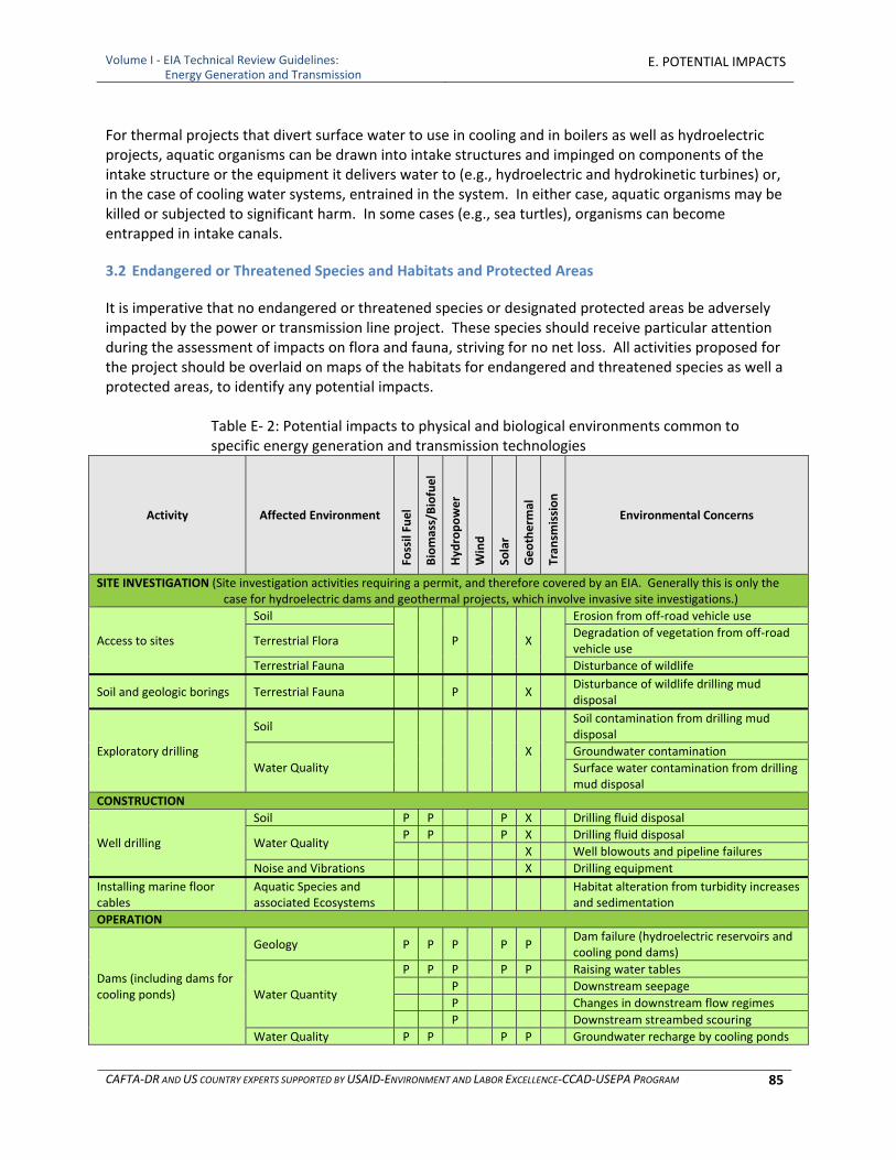
Volume I ‐ EIA Technical Review Guidelines: Energy Generation and Transmission
E. POTENTIAL IMPACTS
CAFTA‐DR AND US COUNTRY EXPERTS SUPPORTED BY USAID‐ENVIRONMENT AND LABOR EXCELLENCE‐CCAD‐USEPA PROGRAM 85
For thermal projects that divert surface water to use in cooling and in boilers as well as hydroelectric projects, aquatic organisms can be drawn into intake structures and impinged on components of the intake structure or the equipment it delivers water to (e.g., hydroelectric and hydrokinetic turbines) or, in the case of cooling water systems, entrained in the system. In either case, aquatic organisms may be killed or subjected to significant harm. In some cases (e.g., sea turtles), organisms can become entrapped in intake canals.
3.2 Endangered or Threatened Species and Habitats and Protected Areas
It is imperative that no endangered or threatened species or designated protected areas be adversely impacted by the power or transmission line project. These species should receive particular attention during the assessment of impacts on flora and fauna, striving for no net loss. All activities proposed for the project should be overlaid on maps of the habitats for endangered and threatened species as well a protected areas, to identify any potential impacts.
Table E‐ 2: Potential impacts to physical and biological environments common to specific energy generation and transmission technologies
Activity Affected Environment
Fossil Fuel
Biomass/Biofuel
Hyd
ropower
Wind
Solar
Geotherm
al
Tran
smission
Environmental Concerns
SITE INVESTIGATION (Site investigation activities requiring a permit, and therefore covered by an EIA. Generally this is only the case for hydroelectric dams and geothermal projects, which involve invasive site investigations.)
Access to sites
Soil
P X
Erosion from off‐road vehicle use
Terrestrial Flora Degradation of vegetation from off‐road vehicle use
Terrestrial Fauna Disturbance of wildlife
Soil and geologic borings Terrestrial Fauna P X Disturbance of wildlife drilling mud disposal
Exploratory drilling
Soil
X
Soil contamination from drilling mud disposal
Water Quality Groundwater contamination
Surface water contamination from drilling mud disposal
CONSTRUCTION
Well drilling
Soil P P P X Drilling fluid disposal
Water Quality P P P X Drilling fluid disposal
X Well blowouts and pipeline failures
Noise and Vibrations X Drilling equipment
Installing marine floor cables
Aquatic Species and associated Ecosystems
Habitat alteration from turbidity increases and sedimentation
OPERATION
Dams (including dams for cooling ponds)
Geology P P P P P Dam failure (hydroelectric reservoirs and cooling pond dams)
Water Quantity
P P P P P Raising water tables
P Downstream seepage
P Changes in downstream flow regimes
P Downstream streambed scouring
Water Quality P P P P Groundwater recharge by cooling ponds
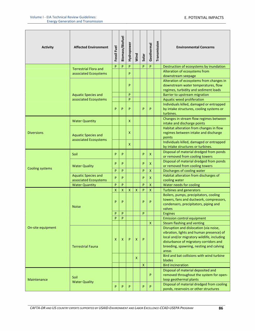
Volume I ‐ EIA Technical Review Guidelines: Energy Generation and Transmission
E. POTENTIAL IMPACTS
CAFTA‐DR AND US COUNTRY EXPERTS SUPPORTED BY USAID‐ENVIRONMENT AND LABOR EXCELLENCE‐CCAD‐USEPA PROGRAM 86
Activity Affected Environment
Fossil Fuel
Biomass/Biofuel
Hyd
ropower
Wind
Solar
Geotherm
al
Tran
smission
Environmental Concerns
Terrestrial Flora and associated Ecosystems
P P P P P Destruction of ecosystems by inundation
P Alteration of ecosystems from downstream seepage
Aquatic Species and associated Ecosystems
P Alteration of ecosystems from changes in downstream water temperatures, flow regimes, turbidity and sediment loads
P Barrier to upstream migration
P Aquatic weed proliferation
P P P P P Individuals killed, damaged or entrapped by intake structures, cooling systems or turbines.
Diversions
Water Quantity X Changes in stream flow regimes between intake and discharge points
Aquatic Species and associated Ecosystems
X Habitat alteration from changes in flow regimes between intake and discharge points
X Individuals killed, damaged or entrapped by intake structures or turbines.
Cooling systems
Soil P P P X Disposal of material dredged from ponds or removed from cooling towers
Water Quality P P P X
Disposal of material dredged from ponds or removed from cooling towers
P P P X Discharges of cooling water
Aquatic Species and associated Ecosystems
P P P X Habitat alteration from discharges of cooling water
Water Quantity P P P X Water needs for cooling
On‐site equipment
Noise
X X X X P X Turbines and generators
P P P P
Boilers, pumps, precipitators, cooling towers, fans and ductwork, compressors, condensers, precipitators, piping and valves
P P P Engines
P P Emission control equipment
X Steam flashing and venting
Terrestrial Fauna
X X P X P
Disruption and dislocation (via noise, vibration, lights and human presence) of local and/or migratory wildlife, including disturbance of migratory corridors and breeding, spawning, nesting and calving areas
X Bird and bat collisions with wind turbine blades
X Bird incineration
Maintenance Soil Water Quality
P Disposal of material deposited and removed throughout the system for open‐loop geothermal plants
P P P P P Disposal of material dredged from cooling ponds, reservoirs or other structures
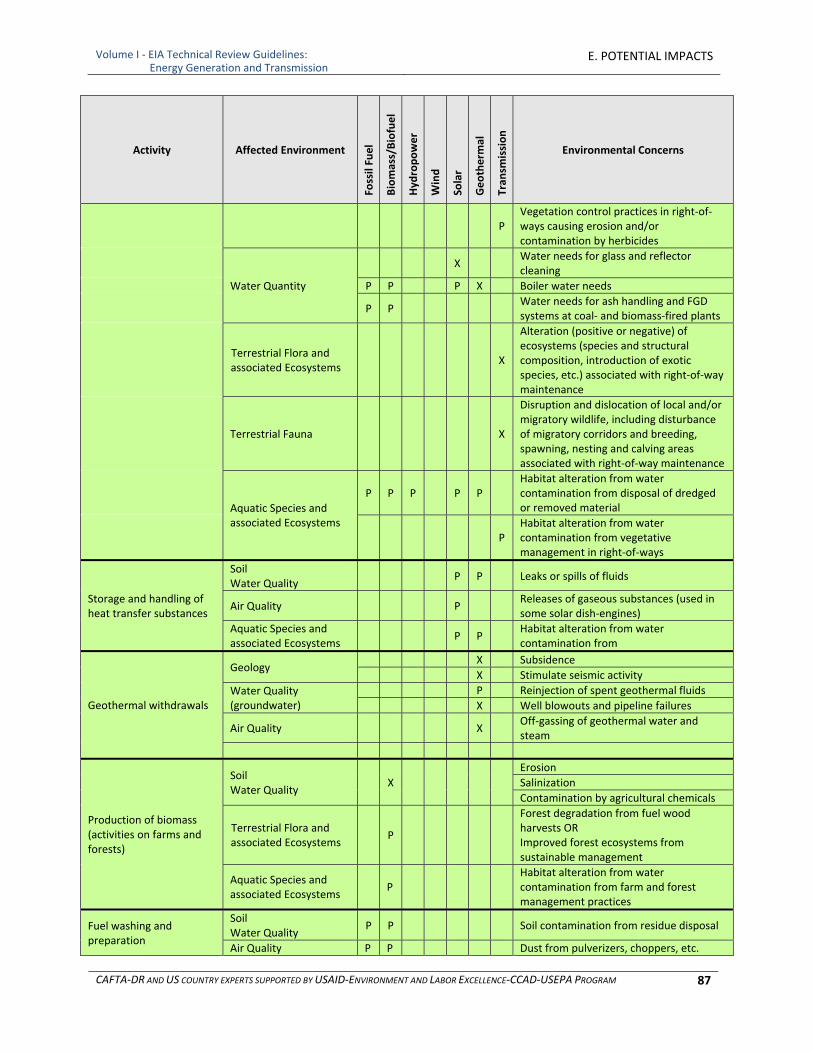
Volume I ‐ EIA Technical Review Guidelines: Energy Generation and Transmission
E. POTENTIAL IMPACTS
CAFTA‐DR AND US COUNTRY EXPERTS SUPPORTED BY USAID‐ENVIRONMENT AND LABOR EXCELLENCE‐CCAD‐USEPA PROGRAM 87
Activity Affected Environment
Fossil Fuel
Biomass/Biofuel
Hyd
ropower
Wind
Solar
Geotherm
al
Tran
smission
Environmental Concerns
P Vegetation control practices in right‐of‐ways causing erosion and/or contamination by herbicides
Water Quantity
X Water needs for glass and reflector cleaning
P P P X Boiler water needs
P P Water needs for ash handling and FGD systems at coal‐ and biomass‐fired plants
Terrestrial Flora and associated Ecosystems
X
Alteration (positive or negative) of ecosystems (species and structural composition, introduction of exotic species, etc.) associated with right‐of‐way maintenance
Terrestrial Fauna X
Disruption and dislocation of local and/or migratory wildlife, including disturbance of migratory corridors and breeding, spawning, nesting and calving areas associated with right‐of‐way maintenance
Aquatic Species and associated Ecosystems
P P P P P Habitat alteration from water contamination from disposal of dredged or removed material
P Habitat alteration from water contamination from vegetative management in right‐of‐ways
Storage and handling of heat transfer substances
Soil Water Quality
P P Leaks or spills of fluids
Air Quality P Releases of gaseous substances (used in some solar dish‐engines)
Aquatic Species and associated Ecosystems
P P Habitat alteration from water contamination from
Geothermal withdrawals
Geology X Subsidence
X Stimulate seismic activity
Water Quality (groundwater)
P Reinjection of spent geothermal fluids
X Well blowouts and pipeline failures
Air Quality X Off‐gassing of geothermal water and steam
Production of biomass (activities on farms and forests)
Soil Water Quality
X
Erosion
Salinization
Contamination by agricultural chemicals
Terrestrial Flora and associated Ecosystems
P
Forest degradation from fuel wood harvests OR Improved forest ecosystems from sustainable management
Aquatic Species and associated Ecosystems
P
Habitat alteration from water contamination from farm and forest management practices
Fuel washing and preparation
Soil Water Quality
P P
Soil contamination from residue disposal
Air Quality P P Dust from pulverizers, choppers, etc.
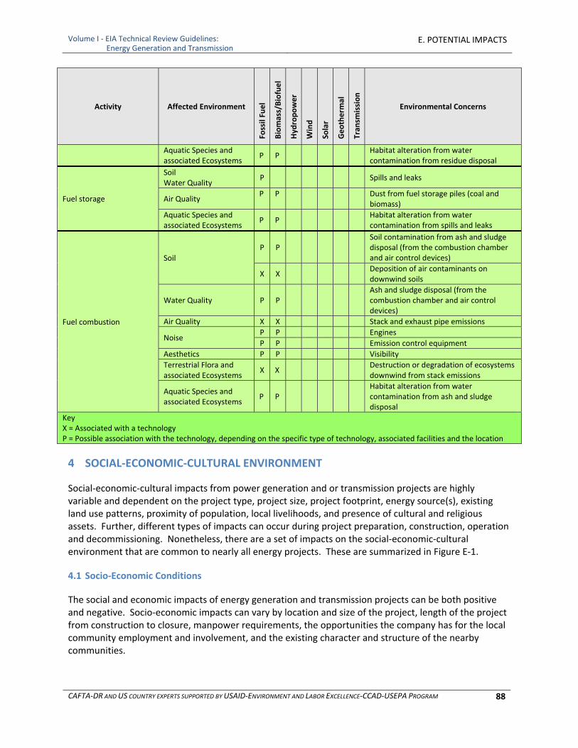
Volume I ‐ EIA Technical Review Guidelines: Energy Generation and Transmission
E. POTENTIAL IMPACTS
CAFTA‐DR AND US COUNTRY EXPERTS SUPPORTED BY USAID‐ENVIRONMENT AND LABOR EXCELLENCE‐CCAD‐USEPA PROGRAM 88
Activity Affected Environment
Fossil Fuel
Biomass/Biofuel
Hyd
ropower
Wind
Solar
Geotherm
al
Tran
smission
Environmental Concerns
Aquatic Species and associated Ecosystems
P P Habitat alteration from water
contamination from residue disposal
Fuel storage
Soil Water Quality
P
Spills and leaks
Air Quality P P Dust from fuel storage piles (coal and
biomass)
Aquatic Species and associated Ecosystems
P P Habitat alteration from water
contamination from spills and leaks
Fuel combustion
Soil P P
Soil contamination from ash and sludge disposal (from the combustion chamber and air control devices)
X X Deposition of air contaminants on downwind soils
Water Quality P P Ash and sludge disposal (from the combustion chamber and air control devices)
Air Quality X X Stack and exhaust pipe emissions
Noise P P Engines
P P Emission control equipment
Aesthetics P P Visibility
Terrestrial Flora and associated Ecosystems
X X Destruction or degradation of ecosystems downwind from stack emissions
Aquatic Species and associated Ecosystems
P P Habitat alteration from water
contamination from ash and sludge disposal
Key X = Associated with a technology P = Possible association with the technology, depending on the specific type of technology, associated facilities and the location
4 SOCIAL‐ECONOMIC‐CULTURAL ENVIRONMENT
Social‐economic‐cultural impacts from power generation and or transmission projects are highly variable and dependent on the project type, project size, project footprint, energy source(s), existing land use patterns, proximity of population, local livelihoods, and presence of cultural and religious assets. Further, different types of impacts can occur during project preparation, construction, operation and decommissioning. Nonetheless, there are a set of impacts on the social‐economic‐cultural environment that are common to nearly all energy projects. These are summarized in Figure E‐1.
4.1 Socio‐Economic Conditions
The social and economic impacts of energy generation and transmission projects can be both positive and negative. Socio‐economic impacts can vary by location and size of the project, length of the project from construction to closure, manpower requirements, the opportunities the company has for the local community employment and involvement, and the existing character and structure of the nearby communities.
Volume I ‐ EIA Technical Review Guidelines: Energy Generation and Transmission
E. POTENTIAL IMPACTS
CAFTA‐DR AND US COUNTRY EXPERTS SUPPORTED BY USAID‐ENVIRONMENT AND LABOR EXCELLENCE‐CCAD‐USEPA PROGRAM 89
Positive impacts can potentially include:
Increased individual incomes ○ Direct employment on the project ○ Indirect employment generated by project activities ○ Increased purchases from local businesses ○ Other economic activities stimulated in the community as a result of the project
Employment opportunities for local residents (short‐ and long‐term)
Increased tax base
Less expensive and more reliable electric power Negative impacts can potentially include:
Displacement and relocation of current settlements, residents or community resources
Displacement or disruption of people’s livelihoods (e.g., fishing, hunting, grazing, farming, forestry and tourism)
Public finance requirements – more infrastructure and services needed to meet the demands of increased population (e.g., public education, policing, fire protection, water, sanitation, roads)
Increased traffic and truck trips (safety, noise, exhaust)
Reduction in quality of life for residents from visual and noise impacts
Impacts on public health (not applicable to all projects) ○ Water‐related vector diseases (malaria, dengue, etc.) ○ Health impacts of pesticide and fertilizer use
Impacts on worker health and safety ○ Identification of hazardous jobs and number of workers exposed with duration of exposure ○ Occupational diseases due to exposure to dust and other project related activities such as
handling of explosives, solvents, petroleum products, etc. ○ Identification of physical risks and safety aspects
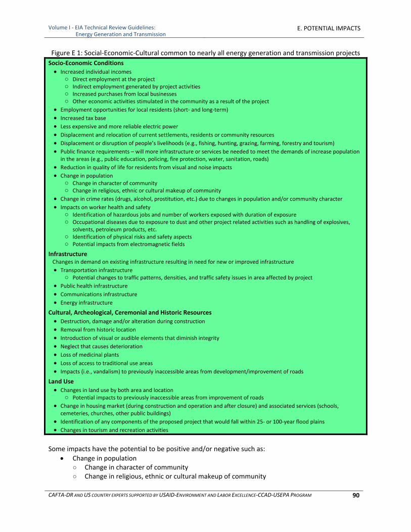
Volume I ‐ EIA Technical Review Guidelines: Energy Generation and Transmission
E. POTENTIAL IMPACTS
CAFTA‐DR AND US COUNTRY EXPERTS SUPPORTED BY USAID‐ENVIRONMENT AND LABOR EXCELLENCE‐CCAD‐USEPA PROGRAM 90
Figure E 1: Social‐Economic‐Cultural common to nearly all energy generation and transmission projects
Socio‐Economic Conditions
Increased individual incomes ○ Direct employment at the project ○ Indirect employment generated by project activities ○ Increased purchases from local businesses ○ Other economic activities stimulated in the community as a result of the project
Employment opportunities for local residents (short‐ and long‐term)
Increased tax base Less expensive and more reliable electric power
Displacement and relocation of current settlements, residents or community resources
Displacement or disruption of people’s livelihoods (e.g., fishing, hunting, grazing, farming, forestry and tourism)
Public finance requirements – will more infrastructure or services be needed to meet the demands of increase population in the areas (e.g., public education, policing, fire protection, water, sanitation, roads)
Reduction in quality of life for residents from visual and noise impacts
Change in population ○ Change in character of community ○ Change in religious, ethnic or cultural makeup of community
Change in crime rates (drugs, alcohol, prostitution, etc.) due to changes in population and/or community character
Impacts on worker health and safety ○ Identification of hazardous jobs and number of workers exposed with duration of exposure ○ Occupational diseases due to exposure to dust and other project related activities such as handling of explosives,
solvents, petroleum products, etc. ○ Identification of physical risks and safety aspects ○ Potential impacts from electromagnetic fields
Infrastructure Changes in demand on existing infrastructure resulting in need for new or improved infrastructure
Transportation infrastructure ○ Potential changes to traffic patterns, densities, and traffic safety issues in area affected by project
Public health infrastructure Communications infrastructure
Energy infrastructure Cultural, Archeological, Ceremonial and Historic Resources
Destruction, damage and/or alteration during construction
Removal from historic location
Introduction of visual or audible elements that diminish integrity
Neglect that causes deterioration Loss of medicinal plants
Loss of access to traditional use areas Impacts (i.e., vandalism) to previously inaccessible areas from development/improvement of roads
Land Use
Changes in land use by both area and location ○ Potential impacts to previously inaccessible areas from improvement of roads
Change in housing market (during construction and operation and after closure) and associated services (schools, cemeteries, churches, other public buildings)
Identification of any components of the proposed project that would fall within 25‐ or 100‐year flood plains
Changes in tourism and recreation activities
Some impacts have the potential to be positive and/or negative such as:
Change in population ○ Change in character of community ○ Change in religious, ethnic or cultural makeup of community

Volume I ‐ EIA Technical Review Guidelines: Energy Generation and Transmission
E. POTENTIAL IMPACTS
CAFTA‐DR AND US COUNTRY EXPERTS SUPPORTED BY USAID‐ENVIRONMENT AND LABOR EXCELLENCE‐CCAD‐USEPA PROGRAM 91
Change in crime rates (drugs, alcohol, prostitution, etc.) One of the primary socio‐economic concerns is displacement of people through: involuntary or forced taking of land, relocation or loss of shelter, loss of assets (farmlands, forests, fisheries, etc.), and/or loss of income sources or means of livelihood. This is an especially crucial consideration for indigenous people and projects, like hydroelectric dams, that can impact vast areas. Development bank experience indicates that involuntary resettlement under development projects, if unmitigated, often gives rise to severe economic, social and environmental risks arising from a chain of actions following displacement. Production systems are dismantled and people face impoverishment. People are relocated to environments where their productive skills may be less applicable and the competition for resources greater. Community institutions and social networks are weakened. Kin groups are dispersed. Cultural identity, traditional authority and the potential for mutual help are diminished or lost. The impacts on public health will vary with the type of project. Any projects that create water bodies (hydroelectric dams and thermal power plants using cooling ponds) can create habitats for mosquitoes. If dengue fever or malaria is prevalent in the area, these impoundments could increase the population of mosquitoes that carry these diseases. Emissions from thermal/combustion projects can impact health in downwind communities, depending upon the concentrations and the distance to the communities. Any project that runs transmission lines near residences can create electromagnetic fields (EMF). Although there is public concern over the potential health effects associated with exposure to EMF (not only high voltage power lines and substations, but also from everyday household uses of electricity), empirical data is insufficient to demonstrate adverse health effects from exposure to typical EMF levels from power transmissions lines and equipment. Biomass and biofuel projects, in which the production of biomass is included in the scope of the EIA, can have positive economic impacts beyond the operation of the plant. A potential effect of growing trees and other plants for energy is that it could benefit farm economies. Energy crops could provide a steady supplemental income for farmers in off‐seasons or allow them to work unused land without requiring much additional equipment. A special focused analysis to explicitly identify and address potential impacts which may fall disproportionately on vulnerable populations is sometimes warranted. “Environmental justice” is a term first developed in the United States to describe such circumstances. Impact analysis and policy considerations that may be valid for the general population may not adequately capture important impacts on subsets of society. For these communities efforts to protect their environmental health and wellbeing requires further investigation into their special relationship to the environment to assess whether predicted impacts may fall upon them disproportionately heavily. Impacts that may not be considered significant for the general population may overlook potentially significant impacts on these populations without this special focus. Whether these impacts can be anticipated from proposed energy projects depends upon the area of influence of the impacts of the proposed project and the use of the affected resources by populations which may be disproportionately affected typically indigenous peoples, minority or low‐income groups.
Volume I ‐ EIA Technical Review Guidelines: Energy Generation and Transmission
E. POTENTIAL IMPACTS
CAFTA‐DR AND US COUNTRY EXPERTS SUPPORTED BY USAID‐ENVIRONMENT AND LABOR EXCELLENCE‐CCAD‐USEPA PROGRAM 92
4.2 Infrastructure
The impacts on infrastructure of energy generation and transmission projects can be neutral, positive or negative, varying with the location and size of the project, manpower requirements, economic benefits to the community, impact on availability of public funds and the existing infrastructure. The impacted infrastructure can include:
Transportation Infrastructure ○ Existing roads ○ Associated structures (bridges, tunnels, traffic controls, etc.) ○ Airports ○ Railroads
Public Health Infrastructure ○ Drinking water supplies and treatment ○ Wastewater treatment and management ○ Solid and hazardous waste management and treatment
Communications Infrastructure ○ Telephone services (fixed lines and mobile) Associated transmission facilities
○ Radio stations ○ Television stations
Energy Infrastructure ○ Electrical power ○ Fuel stations and storage facilities
For all of these types of infrastructure, the question for the EIA is do they have the capacity to meet the demands the project will create, or will they have to be altered, improved or expanded? Additionally, the EIA should determine if the project will alter the condition of the infrastructure. If the existing infrastructure will not meet the demand of the project, or if the project will impact the condition of the infrastructure, then the project has an impact on infrastructure. For transportation infrastructure, this subsection should addresses impacts of transportation and traffic patterns on existing roads. It should identify any anticipated changes in traffic patterns, densities, and traffic safety. If such changes are identified, the EIA should also estimate their impact on traffic accidents, congestion and noise. Some impacts on infrastructure are unique to particular types of energy projects. A hydroelectric project that includes building a dam will retain sediment behind the dam, thus depriving the river downstream of its sediment load. The downstream river will seek to recapture the sediments by eroding the downstream river bed and banks, potentially undermining bridges and other riverbank structures. It can also cause downstream seepage, which may negatively impact structures in the areas that experience seepage. However, a dam can also provide regulated flow and flood control that can protect downstream structures, and the reservoir that it creates can provide new tourism and fisheries opportunities. Wind turbine blade tips, at their highest point, may reach more than 100 meters in height. If located near airports or known flight paths, a wind farm may impact aircraft safety directly through potential

Volume I ‐ EIA Technical Review Guidelines: Energy Generation and Transmission
E. POTENTIAL IMPACTS
CAFTA‐DR AND US COUNTRY EXPERTS SUPPORTED BY USAID‐ENVIRONMENT AND LABOR EXCELLENCE‐CCAD‐USEPA PROGRAM 93
collision or alteration of flight paths. Similarly, if located near ports, harbors, or known shipping lanes, an offshore wind turbine may impact shipping safety through collision or alteration of vessel traffic. Wind turbines could potentially cause electromagnetic interference with aviation radar and telecommunication systems (e.g., microwave, television, and radio). This interference could be caused by three main mechanisms, namely near‐field effects, diffraction, and reflection or scattering. The nature of the potential impacts depends primarily on the location of the wind turbine relative to the transmitter and receiver.
4.3 Cultural, Archeological, Ceremonial and Historic Resources
Impacts on cultural, archeological, ceremonial and historic resources include any direct or indirect alteration of sites, structures, landmarks or traditional cultural lifestyles and resources associated with those lifestyles. Cultural, archeological, ceremonial and historic resources include: archeological sites, historic buildings, burial grounds, sacred or ceremonial sites, areas used for the collection of materials used in ceremonies or traditional lifestyles, and sites that are important because of their roles in traditional stories. Examples of adverse effects to cultural and historical resources from energy projects may include:
Destruction during construction
Damage and alteration
Removal from historic location
Introduction of visual or audible elements that diminish integrity
Neglect that causes deterioration
Loss of medicinal plants
Loss of access to traditional use areas
Impacts to previously inaccessible areas from development/improvement of roads
4.4 Land Use
Energy projects can impact local land use. Clearly, land use on the project site itself will be modified for the life of the project. This impact, however, varies greatly with the size of the facility site. A small geothermal facility may have little impact whereas a large solar power plant (requiring approximately one square kilometer for every 20 to 60 MW generated) can have a greater impact, and a large hydroelectric reservoir that inundates hundreds of hectares can have considerable impact. Other long‐term impacts can include those associated with roads, rails and other ancillary facilities that may stay in place and be used for many years, possibly even after the project’s life. Projects can impact land use on properties adjacent to the facilities as well as properties through which roads and right‐of‐ways may pass. Land use in these areas can be impacted by visibility, noise, odor, air pollution, and water contamination. The development of new roads also may open up previously inaccessible areas to development. For projects proposing to use biomass as a fuel, the land use impacts can extend to the areas where the biomass is produced. Alternative uses of the bio materials if they were not used for the purpose of generating energy Land use in communities nearby the facility can experience changes due to increased population, demanding more housing, schools, churches, and commercial and public services. For energy
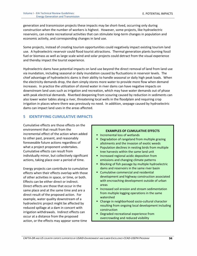
Volume I ‐ EIA Technical Review Guidelines: Energy Generation and Transmission
E. POTENTIAL IMPACTS
CAFTA‐DR AND US COUNTRY EXPERTS SUPPORTED BY USAID‐ENVIRONMENT AND LABOR EXCELLENCE‐CCAD‐USEPA PROGRAM 94
EXAMPLES OF CUMULATIVE EFFECTS Incremental loss of wetlands Degradation of rangeland from multiple grazing
allotments and the invasion of exotic weeds Population declines in nesting birds from multiple
tree harvests within the same land unit Increased regional acidic deposition from
emissions and changing climate patterns Blocking of fish passage by multiple hydroelectric
dams and reservoirs in the same river basin Cumulative commercial and residential
development and highway construction associated with encroaching development outside of urban areas
Increased soil erosion and stream sedimentation from multiple logging operations in the same watershed
Change in neighborhood socio‐cultural character resulting from ongoing local development including construction
Degraded recreational experience from overcrowding and reduced visibility
generation and transmission projects these impacts may be short‐lived, occurring only during construction when the number of workers is highest. However, some projects, like hydroelectric reservoirs, can create recreational activities that can stimulate long‐term changes in population and economic activity, and corresponding changes in land use. Some projects, instead of creating tourism opportunities could negatively impact existing tourism land use. A hydroelectric reservoir could flood tourist attractions. Thermal generation plants burning fossil fuel or biomass as well as large scale wind and solar projects could detract from the visual experience and thereby impact the tourist experience. Hydroelectric dams have potential impacts on land use beyond the direct removal of land from land use via inundation, including seasonal or daily inundation caused by fluctuations in reservoir levels. The chief advantage of hydroelectric dams is their ability to handle seasonal or daily high peak loads. When the electricity demands drop, the dam simply stores more water to provide more flow when demand increases. In practice the utilization of stored water in river dams can have negative impacts on downstream land uses such as irrigation and recreation, which may have water demands out of phase with peak electrical demands. Riverbed deepening from scouring caused by reduction in sediments can also lower water tables along a river, threatening local wells in the floodplain and requiring crop irrigation in places where there was previously no need. In addition, seepage caused by hydroelectric dams can impact land uses in the areas affected.
5 IDENTIFYING CUMULATIVE IMPACTS
Cumulative effects are those effects on the environment that result from the incremental effect of the action when added to other past, present, and reasonably foreseeable future actions regardless of what a project proponent undertakes. Cumulative effects can result from individually minor, but collectively significant actions, taking place over a period of time. Energy projects can contribute to cumulative effects when their effects overlap with those of other activities in space, or time, or both. Effects can be either direct or indirect. Direct effects are those that occur in the same place and at the same time and are a direct result of the proposed action. For example, water quality downstream of a hydroelectric project might be affected by reduced spillage at a dam in concert with irrigation withdrawals. Indirect effects can occur at a distance from the proposed action, or the effects may appear some time
Volume I ‐ EIA Technical Review Guidelines: Energy Generation and Transmission
E. POTENTIAL IMPACTS
CAFTA‐DR AND US COUNTRY EXPERTS SUPPORTED BY USAID‐ENVIRONMENT AND LABOR EXCELLENCE‐CCAD‐USEPA PROGRAM 95
after the proposed action occurs. For example, an upstream timber harvest area and upstream water sewage treatment plant may affect water quality, in addition to the effects on water quality from the proposed action. Although required of EIAs the cumulative impact assessment is often overlooked because many of the actions that need to be taken into account are not within the control of the project proponent, or because methods for cumulative impact assessment may not be apparent. Cumulative impacts may be positive or negative. A new power plant may facilitate taking one or more older, more polluting power plants out of service, and may result in net improvement in environmental conditions. Conversely, installing and operating several small diesel generator stations within a small area, or building several small hydroelectric projects in a given watershed may result in net environmental impacts that exceed those of any one of the projects. In summary, additive or cumulative impacts of the project with those of existing, planned or future activities should be accounted for. This is typically done by adding predicted impacts to existing conditions.
5.1 Identifying Resources that have Potential for Cumulative Impacts
Resources which may require the analysis of cumulative effects described in Chapter F can be identified through the results of any scoping meetings, site visit, public interest in a particular resource; and consultation with the agencies and governmental organizations (NGOs) familiar with or responsible for those resources. Figure E‐2 provides a set of factors to consider in identifying potential cumulative impacts. Additional guidance on defining cumulative analysis resources can be found in: Considering Cumulative Effects under the National Environmental Policy Act (Council on Environmental Quality, 1997), which is available on the web at http://ceq.hss.doe.gov/nepa/ccenepa/ccenepa.htm. An example of the affected environment, or a resource, where operations may cause a cumulative and additive impact would be groundwater usage. In the project area there already may exist wells that are tapping the same aquifer for irrigation, industrial, and municipal uses that the energy project proposes to use for cooling water. Pumping water from that same aquifer may produce a cumulative impact. These uses, when evaluated separately, may not produce a noticeable or measurable decline in the groundwater elevation. However, if these usages are modeled together with the estimated volumes per year of each use and over the time period of planned use, the model may show a cumulative impact of widespread and significant decline in groundwater elevation. A cumulative impact for groundwater, widespread and significant decline in water elevation, then may produce an impact to surface water elevation by lowering stream levels and base flows in nearby streams if there is a hydrologic connection between the aquifer and streams. Declines in groundwater elevations, causing declines in base flows in neighboring streams may produce an impact to habitat critical to wildlife or vegetation therefore impacting certain species of wildlife and vegetation.
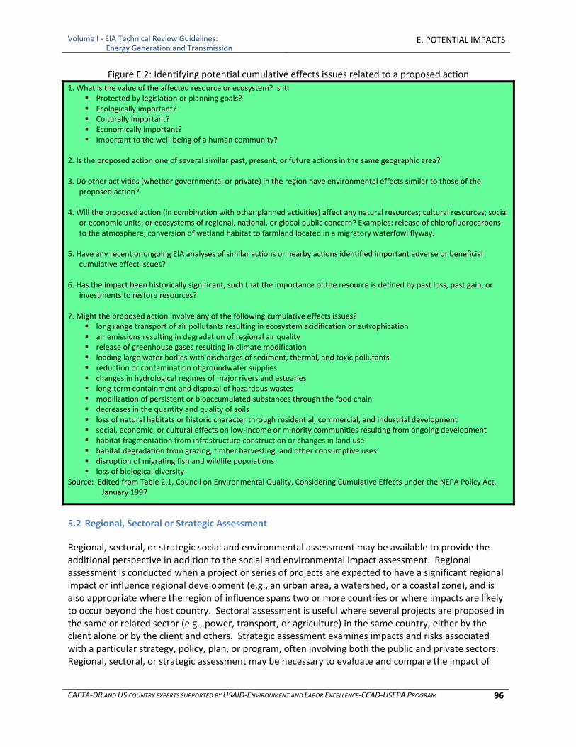
Volume I ‐ EIA Technical Review Guidelines: Energy Generation and Transmission
E. POTENTIAL IMPACTS
CAFTA‐DR AND US COUNTRY EXPERTS SUPPORTED BY USAID‐ENVIRONMENT AND LABOR EXCELLENCE‐CCAD‐USEPA PROGRAM 96
Figure E 2: Identifying potential cumulative effects issues related to a proposed action
1. What is the value of the affected resource or ecosystem? Is it: Protected by legislation or planning goals? Ecologically important? Culturally important? Economically important? Important to the well‐being of a human community?
2. Is the proposed action one of several similar past, present, or future actions in the same geographic area? 3. Do other activities (whether governmental or private) in the region have environmental effects similar to those of the
proposed action? 4. Will the proposed action (in combination with other planned activities) affect any natural resources; cultural resources; social
or economic units; or ecosystems of regional, national, or global public concern? Examples: release of chlorofluorocarbons to the atmosphere; conversion of wetland habitat to farmland located in a migratory waterfowl flyway.
5. Have any recent or ongoing EIA analyses of similar actions or nearby actions identified important adverse or beneficial
cumulative effect issues? 6. Has the impact been historically significant, such that the importance of the resource is defined by past loss, past gain, or
investments to restore resources? 7. Might the proposed action involve any of the following cumulative effects issues?
long range transport of air pollutants resulting in ecosystem acidification or eutrophication air emissions resulting in degradation of regional air quality release of greenhouse gases resulting in climate modification loading large water bodies with discharges of sediment, thermal, and toxic pollutants reduction or contamination of groundwater supplies changes in hydrological regimes of major rivers and estuaries long‐term containment and disposal of hazardous wastes mobilization of persistent or bioaccumulated substances through the food chain decreases in the quantity and quality of soils loss of natural habitats or historic character through residential, commercial, and industrial development social, economic, or cultural effects on low‐income or minority communities resulting from ongoing development habitat fragmentation from infrastructure construction or changes in land use habitat degradation from grazing, timber harvesting, and other consumptive uses disruption of migrating fish and wildlife populations loss of biological diversity
Source: Edited from Table 2.1, Council on Environmental Quality, Considering Cumulative Effects under the NEPA Policy Act, January 1997
5.2 Regional, Sectoral or Strategic Assessment
Regional, sectoral, or strategic social and environmental assessment may be available to provide the additional perspective in addition to the social and environmental impact assessment. Regional assessment is conducted when a project or series of projects are expected to have a significant regional impact or influence regional development (e.g., an urban area, a watershed, or a coastal zone), and is also appropriate where the region of influence spans two or more countries or where impacts are likely to occur beyond the host country. Sectoral assessment is useful where several projects are proposed in the same or related sector (e.g., power, transport, or agriculture) in the same country, either by the client alone or by the client and others. Strategic assessment examines impacts and risks associated with a particular strategy, policy, plan, or program, often involving both the public and private sectors. Regional, sectoral, or strategic assessment may be necessary to evaluate and compare the impact of

Volume I ‐ EIA Technical Review Guidelines: Energy Generation and Transmission
E. POTENTIAL IMPACTS
CAFTA‐DR AND US COUNTRY EXPERTS SUPPORTED BY USAID‐ENVIRONMENT AND LABOR EXCELLENCE‐CCAD‐USEPA PROGRAM 97
alternative development options, assess legal and institutional aspects relevant to the impacts and risks, and recommend broad measures for future social and environmental management. Particular attention is paid to potential cumulative impacts of multiple activities. These assessments are typically carried out by the public sector, though they may be called for in some complex and high risks private sector projects.

Volume I ‐ EIA Technical Review Guidelines: Energy Generation and Transmission
E. POTENTIAL IMPACTS
CAFTA‐DR AND US COUNTRY EXPERTS SUPPORTED BY USAID‐ENVIRONMENT AND LABOR EXCELLENCE‐CCAD‐USEPA PROGRAM 98
[This page Is intentionally blank.]
Volume I ‐ EIA Technical Review Guidelines: Energy Generation and Transmission
F. ASSESSING IMPACTS
CAFTA‐DR AND US COUNTRY EXPERTS SUPPORTED BY USAID‐ENVIRONMENT AND LABOR EXCELLENCE‐CCAD‐USEPA PROGRAM 99
ASSESSING THE IMPACTS OF POWER GENERATION AND TRANSMISSION PROJECTS
Predictive tools can be quantitative – as in the case of analytical or numerical air and water models, semi‐quantitative based on the results of surveys used to evaluate socio‐economic impacts, or qualitative based on professional judgment and comparisons with known impacts of
similar projects and environmental settings.
F. ASSESSING IMPACTS: PREDICTIVE TOOLS AND CONSIDERATIONS
1 OVERVIEW OF PREDICTIVE TOOLS FOR EIA
Environmental impact assessment (EIA) employs predictive tools to determine the locations, magnitude, duration, extent and significance of potential impacts on the environment. EIA for energy sector projects involves a wide range of energy sources and technologies that may be incorporated in a project whose impacts may require the use of a range of predictive tools to assess impacts. The selection of appropriate methods for predicting impacts is important and should be based on sound scientific principles. Many of these methods for predicting impacts are presented in this section of the guidelines.
1.1 Ground Rules: Basic Considerations for Predicting Impacts
The EIA should assess as appropriate the direct, indirect and cumulative impacts for the proposed project including alternatives and for every phase of the project: exploration, site development, construction, operation, maintenance and closure if closure is expected within nominally 20‐30 years. If closure is predicted to be further in to the future then much might have changed in the interim and it is not appropriate to plan for closure at the start of the project. Ground Rules for predicting impacts:
1. Generally accepted scientific practices should be used to estimate potential impacts. 2. Greater detail and analysis should be included for those impacts which are potentially
significant. 3. It will be important to identify uncertainties to lay the groundwork for decisions about the
project, proposed environmental measures, monitoring and contingency plans. 4. The assessment of impacts builds on and indeed depends on a complete and accurate
description of the project and related activities, alternatives and the information on the environmental setting. The assessment may take into account proposed environmental measures incorporated into the siting, design and processes and procedures, but to the extent that this is done in the assessment of impacts, those actions should be included in the Environmental Management section of the EIA which describes the commitments of the project developer to environmental measures activities. In other words, the project proponent cannot assume for purposes of analysis that the impact is half of what it would otherwise be because of a control device and then fail to include that control device in the environmental measures that are committed to for the project. Control technologies proposed are also often part of the project alternatives addressed – balancing cost against benefits.
5. Key assumptions should be explicit in the EIA. Because prediction is only as good as the assumptions and the appropriateness of the tools, information required should be explicitly spelled out in the EIA for the reviewer and decision maker. Although a range of predictive tools may be available, however, the user should justify and validate or qualify the tools and data
Volume I ‐ EIA Technical Review Guidelines: Energy Generation and Transmission
F. ASSESSING IMPACTS
CAFTA‐DR AND US COUNTRY EXPERTS SUPPORTED BY USAID‐ENVIRONMENT AND LABOR EXCELLENCE‐CCAD‐USEPA PROGRAM 100
used based on the site location and situation. Topography, meteorology, hydrology, land use and ground cover, energy input types and rates, and conditions that may be unique to the project site should also be considered.
6. Cumulative impacts should not be ignored. Impacts of project construction and operation should be added to existing and other predicted impacts (other projects already under development), as the overall net impacts should be addressed.
7. To employ predictive tools it usually is necessary to calculate intermediary factors such as the resulting direct emissions or releases into the environment from a given set of activities, or, the area and type of land disturbance, number of employees that may be required during construction phases, and other factors. By applying these intermediary factors to what is known about the environmental setting, predictive tools provide quantitative and qualitative information on the impacts based upon known or anticipated relationships.
1.2 Geographic Boundaries for Assessment of Impacts
The geographic boundaries for assessment of impacts are an important factor in correct assessment of impacts. It is often called the “area of influence”. Determining the geographic boundaries and time periods for the assessment depends on the characteristics of the resources affected, the magnitude and scale of the project's impacts, the timing of the source of impacts, the duration of the impacts, and the environmental setting. In practice, a combination of natural and institutional boundaries may be required to adequately consider both potential impacts and possible environmental measures. Ultimately, the scope of the analysis will depend on an understanding of how the effects are occurring in the assessment area.
1.2.1 Project Footprint
Development of process flow diagrams and associated plot plans is essential to understanding the “footprint” of a project, and potential impacts. Sources, pollutant transport mechanisms and potential impacts within the project boundary and within the area of influence can be more easily understood and addressed if the assessment starts with such graphic overviews of the project. Outputs of numerical predictive models can also be overlaid on plot plans and maps of surrounding areas. Both the footprint of the disturbed area, adjacent areas for temporary storage of equipment, or debris and the final site plan for the project need to be considered in the footprint.
1.2.2 Area of Influence considerations for different resources
Determining the area of influence for a project can be complex. It is rarely limited to the project fence line or a uniform radius around the project site, and may include sensitive and protected areas at greater distances than may be normally thought of as being within the area of influence. Defining the area of influence is often, if not always, variable and dependent on the affected resource, including human health and welfare. Some examples for consideration of geographic boundaries for different resources include:
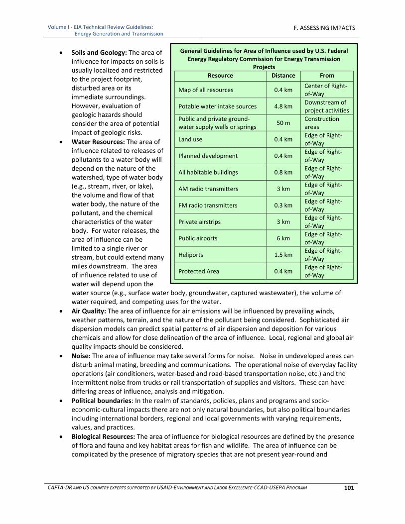
Volume I ‐ EIA Technical Review Guidelines: Energy Generation and Transmission
F. ASSESSING IMPACTS
CAFTA‐DR AND US COUNTRY EXPERTS SUPPORTED BY USAID‐ENVIRONMENT AND LABOR EXCELLENCE‐CCAD‐USEPA PROGRAM 101
Soils and Geology: The area of influence for impacts on soils is usually localized and restricted to the project footprint, disturbed area or its immediate surroundings. However, evaluation of geologic hazards should consider the area of potential impact of geologic risks.
Water Resources: The area of influence related to releases of pollutants to a water body will depend on the nature of the watershed, type of water body (e.g., stream, river, or lake), the volume and flow of that water body, the nature of the pollutant, and the chemical characteristics of the water body. For water releases, the area of influence can be limited to a single river or stream, but could extend many miles downstream. The area of influence related to use of water will depend upon the water source (e.g., surface water body, groundwater, captured wastewater), the volume of water required, and competing uses for the water.
Air Quality: The area of influence for air emissions will be influenced by prevailing winds, weather patterns, terrain, and the nature of the pollutant being considered. Sophisticated air dispersion models can predict spatial patterns of air dispersion and deposition for various chemicals and allow for close delineation of the area of influence. Local, regional and global air quality impacts should be considered.
Noise: The area of influence may take several forms for noise. Noise in undeveloped areas can disturb animal mating, breeding and communications. The operational noise of everyday facility operations (air conditioners, water‐based and road‐based transportation noise, etc.) and the intermittent noise from trucks or rail transportation of supplies and visitors. These can have differing areas of influence, analysis and mitigation.
Political boundaries: In the realm of standards, policies, plans and programs and socio‐economic‐cultural impacts there are not only natural boundaries, but also political boundaries including international borders, regional and local governments with varying requirements, values, and practices.
Biological Resources: The area of influence for biological resources are defined by the presence of flora and fauna and key habitat areas for fish and wildlife. The area of influence can be complicated by the presence of migratory species that are not present year‐round and
General Guidelines for Area of Influence used by U.S. Federal Energy Regulatory Commission for Energy Transmission
Projects
Resource Distance From
Map of all resources 0.4 km Center of Right‐of‐Way
Potable water intake sources 4.8 km Downstream of project activities
Public and private ground‐water supply wells or springs
50 m Construction areas
Land use 0.4 km Edge of Right‐of‐Way
Planned development 0.4 km Edge of Right‐of‐Way
All habitable buildings 0.8 km Edge of Right‐of‐Way
AM radio transmitters 3 km Edge of Right‐of‐Way
FM radio transmitters 0.3 km Edge of Right‐of‐Way
Private airstrips 3 km Edge of Right‐of‐Way
Public airports 6 km Edge of Right‐of‐Way
Heliports 1.5 km Edge of Right‐of‐Way
Protected Area 0.4 km Edge of Right‐of‐Way
Volume I ‐ EIA Technical Review Guidelines: Energy Generation and Transmission
F. ASSESSING IMPACTS
CAFTA‐DR AND US COUNTRY EXPERTS SUPPORTED BY USAID‐ENVIRONMENT AND LABOR EXCELLENCE‐CCAD‐USEPA PROGRAM 102
ecosystems which are sensitive and unique. Thus, areas that are a great distance away from the project can be influenced by the project.
Ecosystems and watersheds: Boundaries would be based on the resources of concern and the characteristics of the specific area to be assessed. In many cases, the analysis should use an ecological region boundary that focuses on the natural units that constitute the resources of concern and geographic areas that sustain the resources of concern. Importantly, the geographical boundaries should not be extended to the point that the analysis becomes unwieldy and useless for decision‐making. In practice, the areas for several target species or components of the ecosystem can often be captured by a single eco‐region or watershed.
Land Use and Socioeconomics: The area of influence may be localized and restricted to the project footprint and immediate surroundings, but because of induced indirect impacts it can be far reaching. The area of influence also will depend on regional socioeconomic conditions and whether the project will alter the essential character of the community, existing or potential uses of the land, infrastructure and the population. The geographic boundary can be quite different in rural as opposed to urban environments.
1.2.3 Considerations based on project phase and duration:
Site Characterization: The area of influence is usually limited to the immediate area of activities.
Construction: The area of influence includes the project footprint and immediate surroundings, and the socioeconomic regions supplying workers.
Operations: The area of influence includes the project footprint and surroundings, areas affected by emissions and effluents, and the socioeconomic regions supplying workers.
Closure: The area of influence includes the project footprint and immediate surroundings, and the socioeconomic regions supplying workers.
Duration of impacts: Determining the temporal scope requires estimating the length of time the effects of the proposed action will last. More specifically, this length of time extends as long as the effects may singly, or in combination with other potential effects, be significant on the resources of concern.
1.2.4 Consideration based on direct, indirect and cumulative impacts:
A project’s direct, indirect and cumulative impacts may affect the area of influence. Generally, the scope of analysis for assessing cumulative impacts will be broader than the scope of analysis used in assessing direct or indirect effects. Spatial and temporal boundaries should not be overly restricted in cumulative impact analysis. However, to avoid extending data and analytical requirements beyond those relevant to decision making, the cumulative impact assessment can stop at the point where the contribution of effects of the action, or combination of all actions, to the cumulative impact is not significant. The important factor in determining cumulative impact is the condition of the resource (i.e., to what extent it is degraded).
An appropriate spatial scope of the cumulative impact analysis by considering how the resources are being affected. This determination involves two basic steps: 1. Identifying a geographic area that includes resources potentially affected by the proposed
project. 2. Extending that area, when necessary, to include the same and other resources affected,
positively or negatively, by the combined impacts of the project and other actions.
Volume I ‐ EIA Technical Review Guidelines: Energy Generation and Transmission
F. ASSESSING IMPACTS
CAFTA‐DR AND US COUNTRY EXPERTS SUPPORTED BY USAID‐ENVIRONMENT AND LABOR EXCELLENCE‐CCAD‐USEPA PROGRAM 103
1.3 Baseline
Impacts are always assessed against a baseline. The baseline used in an EIA is the “no action alternative.” This is a description of the environment in the absence of the proposed project but including consideration of other changes predicted to take place in the absence of the proposal. The baseline for assessing impacts is different from existing conditions as it does consider other changes that may occur in future but independent of the project, e.g., other project start‐ups, closures or major modifications. The geographic and political boundaries for assessing project impacts will depend upon the affected resource and the nature of the potential impacts and may also be influenced by the distances specified by the organization responsible for EIA review, likely specified in the Terms of Reference and/or EIA application form. Section D, Environmental Setting, goes into considerable detail on baseline data requirements. Acquisition or development of accurate baseline data is very important in assessing the environmental impacts of a power generation or transmission project.
1.4 Data Requirements and Sources
Data requirements are determined by the types and locations of impacts to be predicted, and by the predictive tools and model to be used. Sources include direct measurement and monitoring, existing literature, field studies, surveys. As with any numerical modeling exercise, the validity of the output is governed by the appropriateness of model selection, quality of data used, and the experience of the modeler. When data are of unconfirmed quality, of insufficient quantity, are from surrogate operations and locations, or are extrapolated from other studies then results should be duly caveated. Countries which lack some of the data required by experts or to run models for impact assessment can use the approach of “the Best Available Data (BAD)” to substitute simplified evaluation criteria for estimating potential impacts in terms of risk rather than a modeled estimate of tons/acre, Further, some countries have built in adaptive management and monitoring to overcome these uncertainties during project implementation, but this should be done only where there is a basic confidence that significant adverse impacts are unlikely to occur or that required levels of performance can be met. Finally, in some circumstances unlikely scenarios from accidents and natural disasters pose risks that may be beyond existing baseline and trend data but need to be assessed to bound potential impacts and to avoid and/or prepare for adequate response. The Text Box below describes approaches to bound the risks by developing scenarios for these circumstances.

Volume I ‐ EIA Technical Review Guidelines: Energy Generation and Transmission
F. ASSESSING IMPACTS
CAFTA‐DR AND US COUNTRY EXPERTS SUPPORTED BY USAID‐ENVIRONMENT AND LABOR EXCELLENCE‐CCAD‐USEPA PROGRAM 104
ANALYZING AND PREPARING FOR POTENTIAL RISK: USE OF BOUNDING SCENARIO DEVELOPMENT
EIAs for energy projects should include an analysis of risk. The analysis should represent the range of potential impacts of potential accidents and destructive natural events, including those from likely scenarios as well as those from low‐probability, high‐consequence scenarios. (The latter are sometimes referred to as “worst case scenarios” but this term can be misleading.) The analysis of risk should be considered in the design of all structures as well as in the development of spill and catastrophic failure contingency plans.
Modern energy projects utilize state‐of‐the‐art models to predict the potential environmental impacts to water, air and other resources as well as potential exposures to populations at risk. To avoid under‐predicting impacts, models use conservative assumptions and analyze potential accidents or natural disasters with the most severe consequences reasonably foreseeable to occur. These analyses enable the identification of controls to protect human health and the environment even under these unlikely but foreseeable situations. This analytical approach ensures that the risk analyses in the EIA “bound” the potential risks. That is, the analysis represents the full range of risks and will not under‐predict the most severe consequences. There are understandably policy decisions that are inherent in carrying out this type of analysis as to the threshold for defining a reasonable set of assumptions in developing these scenarios,
This approach has been used to design control technologies and emission controls. In the case of accidental spills, dam failure, fires, hurricanes, unforeseen weather events, earthquakes, volcanic eruptions and other events, contingency plans should be applied to:
Emergency notification and evacuation
Fire control
Spill clean up – it is recommended that spill kits are kept at strategic locations throughout the facility site
Warning systems
Medical support
Other items dealing with the health and safety of the workers and the local community In addition, a program should be developed to train project personnel how to react to emergency situations.
In evaluating these scenarios, the regulator should be aware of the environmental and socio‐economic setting to ensure that the conservative assumptions are reasonable. For instance, water management experts reviewing an EIA risk analysis often require that impoundments be designed to handle runoff from a maximum probable rainfall event. The calculation of such an event is based on many years of data. These data may not be available for a particular drainage and information should be gathered from other similar areas if available. In addition, “climate change” may increase the frequency of large storm events possibly making historic data less reliable for predictive purposes. It takes professional judgment to ensure that the right approach is taken. It is also important for the reviewers to ensure that in case of a disaster or emergency that contingency plans are in place.
1.5 Evaluation of the Significance of Impacts
In assessing the environmental impacts of an Energy project one should determine the magnitude, location and significance of the impact.
1.5.1 Quantitative thresholds of Significance
If regulatory criteria standards exist (e.g., air quality standards, water quality standards, radiation exposure standards), these can serve as benchmarks against which impacts can be measured. Exceeding the standards would be considered significant. Impacts would not be considered significant if no exceedance occurred. Some of the CAFTA‐DR countries may lack certain standards that might be used for criteria for determining the significance of an impact. This guideline provides a range of standards used internationally, and for a range of countries that may be used for this purpose in lieu of in the absence of country standards in the absence of regulatory performance standards.

Volume I ‐ EIA Technical Review Guidelines: Energy Generation and Transmission
F. ASSESSING IMPACTS
CAFTA‐DR AND US COUNTRY EXPERTS SUPPORTED BY USAID‐ENVIRONMENT AND LABOR EXCELLENCE‐CCAD‐USEPA PROGRAM 105
If adequate data and analytical procedures are available, specific thresholds that indicate degradation of the resources of concern should be included in the EIA analysis. The thresholds should be practical, scientifically defensible, and fit the scale of the analysis. Thresholds may be set as specific numerical standards (e.g., dissolved oxygen content to assess water quality, particulate matter levels to assess air quality, etc.), qualitative standards that consider biological components of an ecosystem (e.g., riparian condition and presence of particular biophysical attributes), and/or desired management goals (e.g., open space or unaltered habitat). Thresholds should be represented by a measurement that will report the change in resource condition in meaningful units. This change is then evaluated in terms of both the total threshold beyond which the resource degrades to unacceptable levels and the incremental contribution of the proposed action to reaching that threshold. The measurement should be scientifically based.
1.5.2 Professional Judgment to assess significance of impacts:
Establishing criteria for insignificant and significant impacts may also rely on professional judgment, but these should be well‐defined in the assessment. Criteria often need to be established separately for each resource. The idea of direct and indirect, or secondary impacts should also be considered, whereas loss of jobs by persons and industries who depend on the forest or other systems depend on the forest would be a secondary or indirect impact. ○ Area of Influence: Discussed in subsection 1.2. ○ Percentage of Resource Affected: This can include habitat, land use, and water resources. ○ Persistence of Impacts: Permanent or long‐term changes are usually more significant than
temporary ones. The ability of the resource to recover after the activities are complete is related to this effect.
○ Sensitivity of Resources: Impacts to sensitive resources are usually more significant than impacts to those that are relatively resilient to impacts.
○ Status of Resources: Impacts to rare or limited resources are usually considered more significant than impacts to common or abundant resources.
○ Regulatory Status: Impacts to resources that are protected (e.g., endangered species, wetlands, air quality, cultural resources, water quality) typically are considered more significant than impacts to those without regulatory status. Note that many resources with regulatory status are rare or limited.
○ Societal Value: Some resources have societal value, such as sacred sites, traditional subsistence resources, and recreational areas.
1.5.3 For some purposes qualitative assessment criteria may be used such as:
○ None: No discernable or measurable impacts. ○ Small: Environmental effects are at the lower limits of detection or are so minor that they
will neither destabilize nor noticeably alter any important attribute of the resource. ○ Moderate: Environmental effects are sufficient to noticeably alter important attributes of
the resource but not to destabilize them. ○ Large: Environmental effects are clearly noticeable and are sufficient to destabilize the
resource.
1.5.4 Checklists and Matrices
Checklist and matrices can be used to assist in the identification of possible impacts, categorization of a project or valuation of the significance of impacts across a wide spectrum of potential sources and
Volume I ‐ EIA Technical Review Guidelines: Energy Generation and Transmission
F. ASSESSING IMPACTS
CAFTA‐DR AND US COUNTRY EXPERTS SUPPORTED BY USAID‐ENVIRONMENT AND LABOR EXCELLENCE‐CCAD‐USEPA PROGRAM 106
impacts. The use of checklists for identifying and, to a limited extent, characterizing, environmental impacts, is very common throughout existing EIA processes. A checklist forces the assessment to consider a standardized set of activities or effects for each proposed action, thus bringing uniformity to the assessment process. Checklists can be used to determine environmental impact thresholds, thus indicating whether a full‐scale EIA is needed for a particular project or whether a finding of no significant impact might be issued. The evolution from checklist to matrix is intuitively and easily accomplished. A checklist can be viewed as a single‐column summary of a proposed action, with only a coarse characterization of the nature and magnitude of potential environmental impacts provided. An EIA matrix provides a finer degree of impact characterization by associating a set of columns (actions) with each row (environmental attribute) of the matrix and assigning some value to the effect. Matrices are very likely the most popular and widely used EIA methodology. One common application is in the comparison of alternative actions. Alternative actions (measures, projects, sites, designs) are listed as column headings, while the rows are the criteria that should determine the choice of alternative. In each cell of the matrix, a conclusion can be listed indicating whether the alternative action is likely to have a positive or negative effect relative to the indicated criterion. Very often, the conclusion is stated as a numerical value or symbol indicating the level of intensity of the effect. There is an opportunity, moreover, to apply relative weighting to the various criteria when evaluating the completed matrix. The Asian Development Bank (ADB) Rapid Environmental Assessment (REA) checklists, Leopold Matrix approach, and the valuation matrix used by Costa Rica to assess environmental feasibility are discussed in the following sections.
1.5.4.1 Rapid Environmental Assessment Checklists
Rapid Environmental Assessment (REA) checklists allow a rapid, initial assessment of environmental impacts developed and used by the World Bank and regional development banks. The Asian Development Bank (ADB) REA checklist approach is an excellent means by which the possible environmental and social impacts of any given project can be initially assessed. The approach assists in assuring that from the start there are no serious errors or omissions with respect to possible impacts. The approach is also useful in comparing possible environmental and socio‐economic impacts of alternative projects and/or of the same project on different sites. Figure F‐1 presents the contents of the ADB REA checklist for projects in general. Appendix F in Volume 2 of these guidelines presents the ADB REA checklists for energy projects (Hydropower, Power Transmission, Solar Energy, Thermal Power Plants, and Wind Energy).
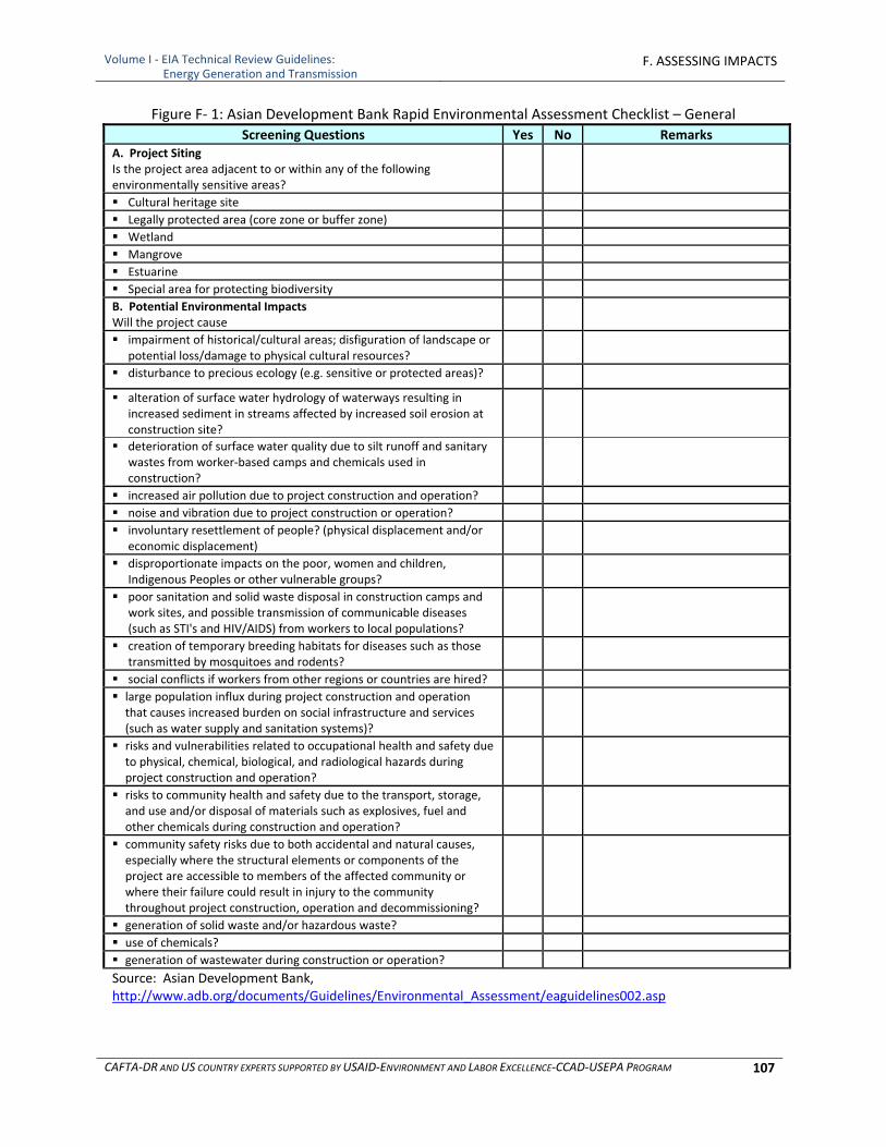
Volume I ‐ EIA Technical Review Guidelines: Energy Generation and Transmission
F. ASSESSING IMPACTS
CAFTA‐DR AND US COUNTRY EXPERTS SUPPORTED BY USAID‐ENVIRONMENT AND LABOR EXCELLENCE‐CCAD‐USEPA PROGRAM 107
Figure F‐ 1: Asian Development Bank Rapid Environmental Assessment Checklist – General
Screening Questions Yes No Remarks A. Project Siting Is the project area adjacent to or within any of the following environmentally sensitive areas?
Cultural heritage site
Legally protected area (core zone or buffer zone)
Wetland
Mangrove
Estuarine
Special area for protecting biodiversity
B. Potential Environmental Impacts Will the project cause
impairment of historical/cultural areas; disfiguration of landscape or potential loss/damage to physical cultural resources?
disturbance to precious ecology (e.g. sensitive or protected areas)?
alteration of surface water hydrology of waterways resulting in increased sediment in streams affected by increased soil erosion at construction site?
deterioration of surface water quality due to silt runoff and sanitary wastes from worker‐based camps and chemicals used in construction?
increased air pollution due to project construction and operation?
noise and vibration due to project construction or operation?
involuntary resettlement of people? (physical displacement and/or economic displacement)
disproportionate impacts on the poor, women and children, Indigenous Peoples or other vulnerable groups?
poor sanitation and solid waste disposal in construction camps and work sites, and possible transmission of communicable diseases (such as STI's and HIV/AIDS) from workers to local populations?
creation of temporary breeding habitats for diseases such as those transmitted by mosquitoes and rodents?
social conflicts if workers from other regions or countries are hired?
large population influx during project construction and operation that causes increased burden on social infrastructure and services (such as water supply and sanitation systems)?
risks and vulnerabilities related to occupational health and safety due to physical, chemical, biological, and radiological hazards during project construction and operation?
risks to community health and safety due to the transport, storage, and use and/or disposal of materials such as explosives, fuel and other chemicals during construction and operation?
community safety risks due to both accidental and natural causes, especially where the structural elements or components of the project are accessible to members of the affected community or where their failure could result in injury to the community throughout project construction, operation and decommissioning?
generation of solid waste and/or hazardous waste?
use of chemicals?
generation of wastewater during construction or operation?
Source: Asian Development Bank, http://www.adb.org/documents/Guidelines/Environmental_Assessment/eaguidelines002.asp

Volume I ‐ EIA Technical Review Guidelines: Energy Generation and Transmission
F. ASSESSING IMPACTS
CAFTA‐DR AND US COUNTRY EXPERTS SUPPORTED BY USAID‐ENVIRONMENT AND LABOR EXCELLENCE‐CCAD‐USEPA PROGRAM 108
1.5.4.2 Leopold Matrix
The Leopold Matrix is a qualitative EIA method pioneered in 1971 by the United States Geological Survey (Leopold et al. 1971). It is used to identify the potential impact of a project on the environment. The system consists of a matrix with columns representing the various activities of the project, and rows representing the various environmental attributes or factors to be considered. The original Leopold Matrix consisted of 100 columns representing examples of causative actions, and 88 rows representing environmental components and characteristics (a portion of the matrix is presented in Figure F‐2). As a first step, the columns that correspond with the nature of the proposed action are checked off. Then, for each column that is marked, the cells corresponding to environmental effects are examined. Two scores (on a scale from 1 to 10) are listed in each cell, separated by a slash (/); the first score represents the magnitude of the possible impact, while the second score represents the importance of the possible impact. Beneficial impacts are indicated by a plus (+) sign and negative impacts with a minus (‐) sign. The interpretation of the matrix is based on the professional judgment of those individuals performing the EIA. Measurements of magnitude and importance tend to be related, but do not necessarily directly correlate. Magnitude can be measured fairly explicitly, in terms of how much area is affected by the development and how adversely, but importance is a more subjective measurement. While a proposed development may have a large impact in terms of magnitude, the effects it causes may not actually significantly affect the environment as a whole.
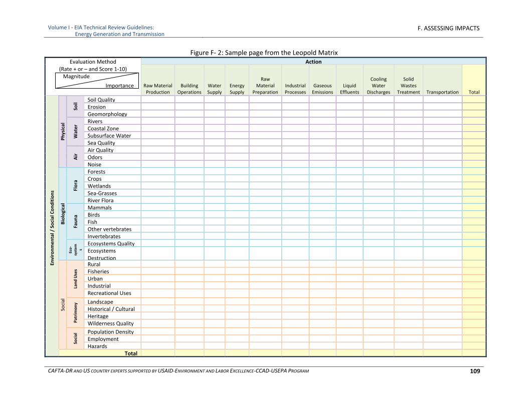
Volume I ‐ EIA Technical Review Guidelines: Energy Generation and Transmission
F. ASSESSING IMPACTS
CAFTA‐DR AND US COUNTRY EXPERTS SUPPORTED BY USAID‐ENVIRONMENT AND LABOR EXCELLENCE‐CCAD‐USEPA PROGRAM 109
Figure F‐ 2: Sample page from the Leopold Matrix Evaluation Method
(Rate + or – and Score 1‐10) Magnitude
Importance
Action
Raw Material Production
Building Operations
Water Supply
Energy Supply
Raw Material
Preparation Industrial Processes
Gaseous Emissions
Liquid Effluents
Cooling Water
Discharges
Solid Wastes
Treatment Transportation Total
Environmental / Social Conditions
Physical
Soil
Soil Quality Erosion Geomorphology
Water
Rivers Coastal Zone Subsurface Water Sea Quality
Air Air Quality
Odors Noise
Biological
Flora
Forests Crops Wetlands Sea‐Grasses River Flora
Fauna
Mammals Birds Fish Other vertebrates Invertebrates
Eco‐
system
s
Ecosystems Quality Ecosystems Destruction
Social
Land Uses
Rural Fisheries Urban Industrial Recreational Uses
Patrimony Landscape
Historical / Cultural Heritage Wilderness Quality
Social Population Density
Employment Hazards
Total
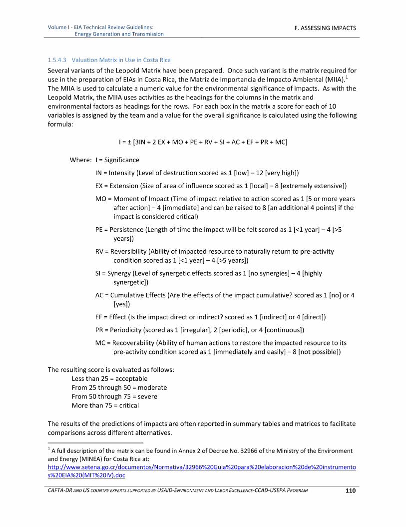
Volume I ‐ EIA Technical Review Guidelines: Energy Generation and Transmission
F. ASSESSING IMPACTS
CAFTA‐DR AND US COUNTRY EXPERTS SUPPORTED BY USAID‐ENVIRONMENT AND LABOR EXCELLENCE‐CCAD‐USEPA PROGRAM 110
1.5.4.3 Valuation Matrix in Use in Costa Rica
Several variants of the Leopold Matrix have been prepared. Once such variant is the matrix required for use in the preparation of EIAs in Costa Rica, the Matriz de Importancia de Impacto Ambiental (MIIA).1 The MIIA is used to calculate a numeric value for the environmental significance of impacts. As with the Leopold Matrix, the MIIA uses activities as the headings for the columns in the matrix and environmental factors as headings for the rows. For each box in the matrix a score for each of 10 variables is assigned by the team and a value for the overall significance is calculated using the following formula:
I = ± [3IN + 2 EX + MO + PE + RV + SI + AC + EF + PR + MC]
Where: I = Significance
IN = Intensity (Level of destruction scored as 1 [low] – 12 [very high])
EX = Extension (Size of area of influence scored as 1 [local] – 8 [extremely extensive])
MO = Moment of Impact (Time of impact relative to action scored as 1 [5 or more years after action] – 4 [immediate] and can be raised to 8 [an additional 4 points] if the impact is considered critical)
PE = Persistence (Length of time the impact will be felt scored as 1 [<1 year] – 4 [>5 years])
RV = Reversibility (Ability of impacted resource to naturally return to pre‐activity condition scored as 1 [<1 year] – 4 [>5 years])
SI = Synergy (Level of synergetic effects scored as 1 [no synergies] – 4 [highly synergetic])
AC = Cumulative Effects (Are the effects of the impact cumulative? scored as 1 [no] or 4 [yes])
EF = Effect (Is the impact direct or indirect? scored as 1 [indirect] or 4 [direct])
PR = Periodicity (scored as 1 [irregular], 2 [periodic], or 4 [continuous])
MC = Recoverability (Ability of human actions to restore the impacted resource to its pre‐activity condition scored as 1 [immediately and easily] – 8 [not possible])
The resulting score is evaluated as follows: Less than 25 = acceptable From 25 through 50 = moderate From 50 through 75 = severe More than 75 = critical
The results of the predictions of impacts are often reported in summary tables and matrices to facilitate comparisons across different alternatives.
1 A full description of the matrix can be found in Annex 2 of Decree No. 32966 of the Ministry of the Environment and Energy (MINEA) for Costa Rica at: http://www.setena.go.cr/documentos/Normativa/32966%20Guia%20para%20elaboracion%20de%20instrumentos%20EIA%20(MIT%20IV).doc
Volume I ‐ EIA Technical Review Guidelines: Energy Generation and Transmission
F. ASSESSING IMPACTS
CAFTA‐DR AND US COUNTRY EXPERTS SUPPORTED BY USAID‐ENVIRONMENT AND LABOR EXCELLENCE‐CCAD‐USEPA PROGRAM 111
1.6 Data Requirements and Sources
Data requirements are determined by the types and locations of impacts to be predicted, and by the model and other tools to be used. Sources include direct measurement and monitoring, existing literature, field studies, surveys. As with any numerical modeling exercise, the validity of the output is governed by the appropriateness of model selection, quality of data used, and the experience of the modeler. When data are of unconfirmed quality, of insufficient quantity, are from surrogate operations and locations, or are extrapolated from other studies then results should be duly caveat.
Countries which lack some of the data required by experts or to run models for impact assessment can use the approach of “the Best Available Data (BAD)” to substitute simplified evaluation criteria for estimating potential impacts in terms of risk rather than a modeled estimate of tons/acre. Further, some countries have built in adaptive management and monitoring to overcome these uncertainties during project implementation, but this should be done only where there is a basic confidence that significant adverse impacts are unlikely to occur or that required levels of performance can be met. Finally, in some circumstances unlikely scenarios from accidents and natural disasters pose risks that may be beyond existing baseline and trend data but need to be assessed to bound potential impacts and to avoid and/or prepare for adequate response. The Text Box below describes approaches to bound the risks by developing scenarios for these circumstances.
2 GENERAL APPROACHES FOR PREDICTION OF IMPACTS
2.1 Predictive Tools
Prediction of impacts on physical, biological and social‐economic‐cultural resources is accomplished by using a variety of predictive techniques, with results compared to accepted criteria, to evaluate the significance of an impact. There are a range of predictive techniques that can be used including
Experts/professional judgment
Extrapolation from past trends/statistical models
Scenarios based upon risks and potential hazards not captured by past trends
Measured resource responses in other similar geographic areas
Modeling of the resource
Geographic information systems For any of these prediction methods, data requirements are determined by the types and locations of impacts to be predicted, and by the conceptual or quantitative model to be used. As with any numerical modeling exercise, the validity of the output is governed by the appropriateness of model selection, quality of data used, and the experience of the modeler. When data are of unconfirmed quality, of insufficient quantity, are from surrogate operations and locations, or are extrapolated from other studies then results should be duly caveated. The remainder of this section of the guidelines identifies quantitative models for assessing impacts as examples of scientifically accepted practices, but criteria for applying a specific methodology in any given circumstances should be carefully assessed and justified, data sources and assumptions made clear and any resulting uncertainties identified. It is important in the development of an EIA that models

Volume I ‐ EIA Technical Review Guidelines: Energy Generation and Transmission
F. ASSESSING IMPACTS
CAFTA‐DR AND US COUNTRY EXPERTS SUPPORTED BY USAID‐ENVIRONMENT AND LABOR EXCELLENCE‐CCAD‐USEPA PROGRAM 112
are used wisely and that the results are not accepted without strenuous review. Quantitative models, calibrated to particular settings and circumstances, are particularly useful to assess impacts to air and water resources as well as potential risks to humans and biota, and may even be required as a consistent and objective approach to evaluating impacts where those models are validated for use in the particular circumstances. One other advantage of using models is that sensitivity analyses can be performed and “what‐if” scenarios can be modeled to identify the nature and extent of impacts and identify which variables contribute to impacts as well as uncertainty of the results.
2.2 Geographic Information Systems and Visualization Tools
To understand the impacts of a project on, it is important to be able to visualize and calculate potential changes which may occur. This can be done by developing maps which show pre‐project and post‐project conditions. In many countries, geographic information system (GIS) is used extensively for this purpose. GIS captures, stores, analyzes, manages, and presents data that is linked to location. GIS applications are tools that allow users to create interactive queries (user created searches), analyze spatial information, edit data, maps, and present the results of all these operations. A GIS includes mapping software and its application with remote sensing, land surveying, aerial photography, mathematics, photogrammetry, geography, and other tools.
ArcGIS is a suite of GIS tools (ArcView, ArcGIS Server, etc) for working with maps and geographic information. It is used for assembling, storing, manipulating and displaying geographically referenced data. ArcGIS is a powerful tool whereby layers of data on a variety of topics can be collated, sieved, selected or superimposed. U.S. EPA has developed an application for screening projects for EIA which uses the off the shelf software of ArcGIS Server to create instantaneous access to distributed sources of data, integrate the data spatially, and provide an analysis of key relationships of environment and social‐economic‐cultural features in both a standardized and flexible manner. This tool has been adapted for use in CAFTA‐DR countries and deployed throughout the region.
2.3 Selecting and Applying Quantitative Predictive Tools
It is important in the development of an EIA that models are used wisely and that the results are not accepted without strenuous review. Needless to say, the advantage of using quantitative models is that sensitivity analyses can be performed and “what‐if” scenarios can be modeled to identify the nature and extent of impacts and identify which variables contribute to impacts as well as uncertainty of the results. When limited baseline data are available or the exact nature of the project is not known, impact determinations using models should be based on a number of assumptions. Each of the assumptions has some uncertainty associated with it. To compensate for these uncertainties, conservative assumptions are usually made to ensure that impacts are not underestimated. Even with conservative assumptions, impacts that are poorly understood (e.g., the response of resources to the environmental changes brought about by the project is not known) can be underestimated or improperly characterized. Conservative assumptions can result in greatly overestimating impacts and unnecessary costs for a project if environmental measures are not properly directed and scaled to the impact. Different countries may also require or accept certain models. It is imperative that such requirements or preferences be determined well in advance of performance of modeling. This will assure that adequate
Volume I ‐ EIA Technical Review Guidelines: Energy Generation and Transmission
F. ASSESSING IMPACTS
CAFTA‐DR AND US COUNTRY EXPERTS SUPPORTED BY USAID‐ENVIRONMENT AND LABOR EXCELLENCE‐CCAD‐USEPA PROGRAM 113
time is allowed to collect input data required by the model(s) and that results are accepted by organizations that must approve the EIA. The following subsections present a brief overview of how these analytical methods can be used in assessing impacts of proposed power generation and transmission projects.
3 SOILS AND GEOLOGY IMPACT ASSESSMENT TOOLS
3.1 Evaluation of impacts due to construction of a power plant or dam
On soils and geology is usually based on professional judgment as well as on existing literature, field studies, surveys, trend analysis or measured resource responses in other geographic areas. Tools such as GIS overlaying activities on maps of soils and geology and graphics generated from comprehensive databases are useful toward visualization and determination of the magnitude of potential impacts. Soil Loss and Erosion Potential For soils, it is important to understand the potential for soil loss due to wind and water erosion. The US Natural Resources Conservation Service developed the wind erosion equation (WEQ) expressed in function form as:
E = f (I, K, C, L, V)
Where: E = the potential average annual soil loss I = the soil erodibility index K = the soil ridge roughness factor C = the climate factor L = unsheltered distance across a field V = the equivalent vegetative cover
Because field erodibility varies with field conditions, a procedure to solve WEQ for periods of less than one year was devised. In this procedure, a series of factor values are selected to describe successive management periods in which both management factors and vegetative covers are nearly constant. Erosive wind energy distribution is used to derive a weighted soil loss for each period. Soil losses for individual periods are summed to estimate annual erosion. Soil loss from the periods also can be summed for multi‐year rotations, and the loss divided by the number of years to obtain an average, annual estimate. The NRCS has also developed the Wind Erosion Prediction System (WEPS) that incorporates this new technology and is designed to be a replacement for the WEQ. Unlike WEQ, WEPS is a process‐based, continuous, daily time‐step model that simulates weather, field conditions, and erosion. It is a user friendly program that has the capability of simulating spatial and temporal variability of field conditions and soil loss/deposition within a field. WEPS can also simulate complex field shapes, barriers not on the field boundaries, and complex topographies. The saltation, creep, suspension, and PM10 components of eroding materials can also be reported separately by direction in WEPS. WEPS is designed to be used under a wide range of conditions in the United States and easily adapted to other parts of the world. For soil loss due to water erosion, estimation can be done using RUSLE described in the box below.
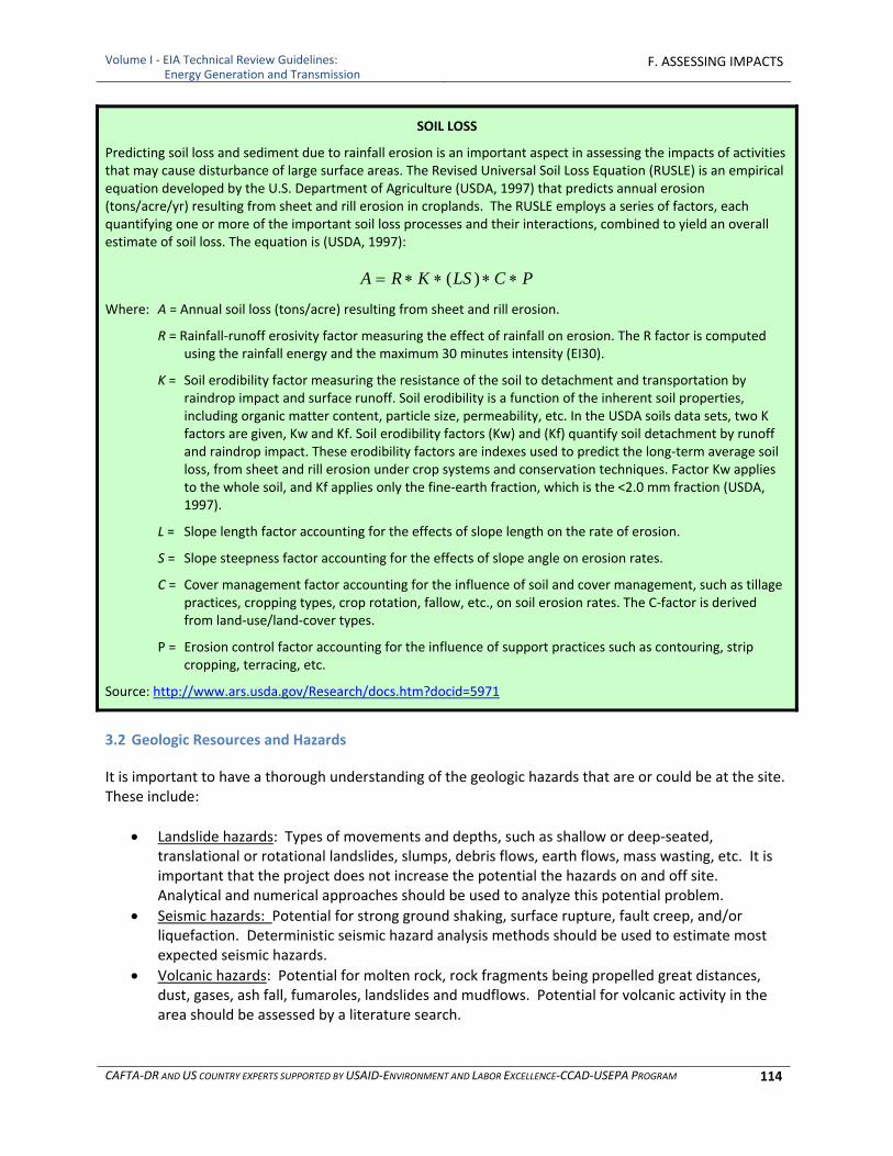
Volume I ‐ EIA Technical Review Guidelines: Energy Generation and Transmission
F. ASSESSING IMPACTS
CAFTA‐DR AND US COUNTRY EXPERTS SUPPORTED BY USAID‐ENVIRONMENT AND LABOR EXCELLENCE‐CCAD‐USEPA PROGRAM 114
SOIL LOSS
Predicting soil loss and sediment due to rainfall erosion is an important aspect in assessing the impacts of activities that may cause disturbance of large surface areas. The Revised Universal Soil Loss Equation (RUSLE) is an empirical equation developed by the U.S. Department of Agriculture (USDA, 1997) that predicts annual erosion (tons/acre/yr) resulting from sheet and rill erosion in croplands. The RUSLE employs a series of factors, each quantifying one or more of the important soil loss processes and their interactions, combined to yield an overall estimate of soil loss. The equation is (USDA, 1997):
PCLSKRA )(
Where: A = Annual soil loss (tons/acre) resulting from sheet and rill erosion.
R = Rainfall‐runoff erosivity factor measuring the effect of rainfall on erosion. The R factor is computed using the rainfall energy and the maximum 30 minutes intensity (EI30).
K = Soil erodibility factor measuring the resistance of the soil to detachment and transportation by raindrop impact and surface runoff. Soil erodibility is a function of the inherent soil properties, including organic matter content, particle size, permeability, etc. In the USDA soils data sets, two K factors are given, Kw and Kf. Soil erodibility factors (Kw) and (Kf) quantify soil detachment by runoff and raindrop impact. These erodibility factors are indexes used to predict the long‐term average soil loss, from sheet and rill erosion under crop systems and conservation techniques. Factor Kw applies to the whole soil, and Kf applies only the fine‐earth fraction, which is the <2.0 mm fraction (USDA, 1997).
L = Slope length factor accounting for the effects of slope length on the rate of erosion.
S = Slope steepness factor accounting for the effects of slope angle on erosion rates.
C = Cover management factor accounting for the influence of soil and cover management, such as tillage practices, cropping types, crop rotation, fallow, etc., on soil erosion rates. The C‐factor is derived from land‐use/land‐cover types.
P = Erosion control factor accounting for the influence of support practices such as contouring, strip cropping, terracing, etc.
Source: http://www.ars.usda.gov/Research/docs.htm?docid=5971
3.2 Geologic Resources and Hazards
It is important to have a thorough understanding of the geologic hazards that are or could be at the site. These include:
Landslide hazards: Types of movements and depths, such as shallow or deep‐seated, translational or rotational landslides, slumps, debris flows, earth flows, mass wasting, etc. It is important that the project does not increase the potential the hazards on and off site. Analytical and numerical approaches should be used to analyze this potential problem.
Seismic hazards: Potential for strong ground shaking, surface rupture, fault creep, and/or liquefaction. Deterministic seismic hazard analysis methods should be used to estimate most expected seismic hazards.
Volcanic hazards: Potential for molten rock, rock fragments being propelled great distances, dust, gases, ash fall, fumaroles, landslides and mudflows. Potential for volcanic activity in the area should be assessed by a literature search.
Volume I ‐ EIA Technical Review Guidelines: Energy Generation and Transmission
F. ASSESSING IMPACTS
CAFTA‐DR AND US COUNTRY EXPERTS SUPPORTED BY USAID‐ENVIRONMENT AND LABOR EXCELLENCE‐CCAD‐USEPA PROGRAM 115
Other geologic hazards (e.g., subsidence, rock fall): In some localities, hazard areas have been identified in the process of developing local critical or sensitive area ordinances. Contact the appropriate local planning departments to obtain the most current information. In some localities, hazard areas are not delineated on maps, but are defined in terms of landscape characteristics (e.g., slope, geologic unit, field indicators). In these instances, hazard areas should be mapped by identifying where the defining characteristics apply to the project area.
4 SOLID WASTE IMPACT ASSESSMENT TOOLS
Solid waste generated during construction and operation will depend on what is built and where, and subsequently what wastes if any are generated as a result of operation. In both instances the assessment tools are generally the calculation of amounts and types of waste generated. Mass and volumes of wastes can be estimated on a mass balance basis. The amounts of hazardous and nonhazardous waste should be calculated separately.
5 WATER RESOURCE IMPACT ASSESSMENT TOOLS
5.1 Surface Water Impact Assessment Tools
For surface water, a useful way to organize the analysis is to take a watershed approach, as presented in the following box.
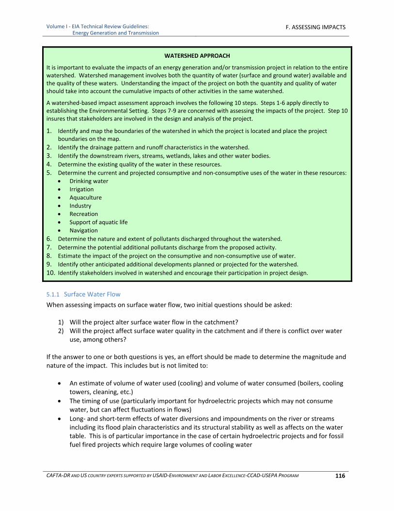
Volume I ‐ EIA Technical Review Guidelines: Energy Generation and Transmission
F. ASSESSING IMPACTS
CAFTA‐DR AND US COUNTRY EXPERTS SUPPORTED BY USAID‐ENVIRONMENT AND LABOR EXCELLENCE‐CCAD‐USEPA PROGRAM 116
WATERSHED APPROACH
It is important to evaluate the impacts of an energy generation and/or transmission project in relation to the entire watershed. Watershed management involves both the quantity of water (surface and ground water) available and the quality of these waters. Understanding the impact of the project on both the quantity and quality of water should take into account the cumulative impacts of other activities in the same watershed.
A watershed‐based impact assessment approach involves the following 10 steps. Steps 1‐6 apply directly to establishing the Environmental Setting. Steps 7‐9 are concerned with assessing the impacts of the project. Step 10 insures that stakeholders are involved in the design and analysis of the project.
1. Identify and map the boundaries of the watershed in which the project is located and place the project boundaries on the map.
2. Identify the drainage pattern and runoff characteristics in the watershed.
3. Identify the downstream rivers, streams, wetlands, lakes and other water bodies.
4. Determine the existing quality of the water in these resources.
5. Determine the current and projected consumptive and non‐consumptive uses of the water in these resources:
Drinking water
Irrigation
Aquaculture
Industry
Recreation
Support of aquatic life
Navigation
6. Determine the nature and extent of pollutants discharged throughout the watershed.
7. Determine the potential additional pollutants discharge from the proposed activity.
8. Estimate the impact of the project on the consumptive and non‐consumptive use of water.
9. Identify other anticipated additional developments planned or projected for the watershed.
10. Identify stakeholders involved in watershed and encourage their participation in project design.
5.1.1 Surface Water Flow
When assessing impacts on surface water flow, two initial questions should be asked:
1) Will the project alter surface water flow in the catchment? 2) Will the project affect surface water quality in the catchment and if there is conflict over water
use, among others? If the answer to one or both questions is yes, an effort should be made to determine the magnitude and nature of the impact. This includes but is not limited to:
An estimate of volume of water used (cooling) and volume of water consumed (boilers, cooling towers, cleaning, etc.)
The timing of use (particularly important for hydroelectric projects which may not consume water, but can affect fluctuations in flows)
Long‐ and short‐term effects of water diversions and impoundments on the river or streams including its flood plain characteristics and its structural stability as well as affects on the water table. This is of particular importance in the case of certain hydroelectric projects and for fossil fuel fired projects which require large volumes of cooling water
Volume I ‐ EIA Technical Review Guidelines: Energy Generation and Transmission
F. ASSESSING IMPACTS
CAFTA‐DR AND US COUNTRY EXPERTS SUPPORTED BY USAID‐ENVIRONMENT AND LABOR EXCELLENCE‐CCAD‐USEPA PROGRAM 117
Affects on flood characteristics in the watershed. This, too, applies primarily to hydroelectric projects where dams are installed or substantial diversion of flow occurs
An accurate understanding of the water balance in the watershed is necessary to successfully manage storm runoff, stream flows, and point and non‐point source pollutant discharges from a power plant site. Natural system waters are fed to the site through rainfall, seeps and springs, groundwater and surface water. Water is lost from the system through surface water runoff, infiltration, and evaporation. Each of these factors is quite variable and difficult to predict. Process and cooling water use is reasonably constant and predictable. Water is lost from the system water through evaporation; facilities such as cooling towers and sedimentation or cooling ponds may result in significant evaporative losses. Spreadsheets are a common way to evaluate water balances on the site. What‐if scenarios can be easily run based on probabilities of rainfall events occurring and changeable weather patterns such as those associated with climate change.
5.1.2 Surface Water Quality
Impacts on surface water quality will depend on the quality of the water discharged from project activities and the assimilative capacity of the receiving water. The assimilative capacity of the receiving water body depends on numerous factors including, but not limited to:
the total volume of water
flow rate
flushing rate of the water body
the loading of pollutants from other effluent sources To estimate impacts of discharges of polluted water on the receiving water body it is necessary to estimate discharge volumes and quality characteristics and characterize existing quantity, quality and performance of the receiving body. Measurements of wastewater quality and baseline water quality should be taken to assure that receiving waters are able to assimilate the waste stream and that incremental effluents will not cause violation of applicable water quality standards, or in the absence of standards, water quality thresholds established for the project. The thresholds should be established for the receiving water and should be developed for parameters that reflect the types of pollutants expected to be discharged. These may include such parameters as pH, oily wastes, additives (e.g., demineralizers in cooling systems), turbidity, dissolved oxygen, and temperature. The intended uses of the water body will influence the setting of threshold levels. Numerical standards for dissolved oxygen and water temperature could be used to determine significance of impacts to fisheries. Prescribed standards for stream condition would be used to determine thresholds for successful fish spawning or other defined uses. This information can also be used to determine potential impacts to downstream water supplies. Thresholds for a decline in water quality can also take the form of the presence and distribution of larval and adult macroinvertebrates and fish species or bioassays performed on indicator species in the laboratory. They may also be set as the size and amount of riparian buffer zones. Condition of riparian zones and changes in percent of buffer areas can indicate a decline in water quality due to soil erosion, sediment loading, and contaminant runoff. The WHO guidelines for recreational use are an example of health based guideline values for receiving waters based on intended use. http://www.who.int/water_sanitation_health/dwq/guidelines/en/index.html. Appendix C identifies

Volume I ‐ EIA Technical Review Guidelines: Energy Generation and Transmission
F. ASSESSING IMPACTS
CAFTA‐DR AND US COUNTRY EXPERTS SUPPORTED BY USAID‐ENVIRONMENT AND LABOR EXCELLENCE‐CCAD‐USEPA PROGRAM 118
some of the current parameters and requirements in place in CAFTA‐DR countries, the United States, other countries and international organizations as a point of reference in the absence of local criteria other recognized criteria
5.1.3 Analytical Approaches
The assessment of impacts to surface water quantity and quality can be done analytically or using numerical models. The following methods are used to determine changes in runoff characteristics and sediment yield due to surface disturbances, primarily during construction. The United States Natural Resources Conservation Service’s procedures for “Estimation of Direct Runoff from Storm Rainfall” is the most common technique for estimating the volume of runoff after a storm event (National Engineering Handbook, Part 630, Chapter 10 http://directives.sc.egov.usda.gov/OpenNonWebContent.aspx?content=17752.wba). The method involves estimating soil‐types within a watershed and applying an appropriate runoff curve number to calculate the volume of excess precipitation for that soil and vegetation cover type. This method was developed for agricultural uses and can be used for power plant sites if sufficient data is available to estimate curve numbers. Curve numbers are approximate values that do not adequately distinguish the hydrologic conditions that occur on different range and forest sites and across different land uses for these sites. A more appropriate technique for developing and analyzing runoff at power plant sites utilizes the unit hydrograph approach as defined in detail at http://www.nohrsc.noaa.gov/technology/gis/uhg_manual.html. A unit hydrograph is a hydrograph of runoff resulting from a unit of rainfall excess that is distributed uniformly over a watershed or sub‐basin in a specified duration of time (Barfield et al., 1981). Unit hydrographs are used to represent the runoff characteristics for particular basins. They are identified by the duration of precipitation excess that was used to generate them; for example, a 1‐hour or a 20‐minute unit hydrograph. The duration of excess precipitation, calculated from actual precipitation events or from design storms, is applied to a unit hydrograph to produce a runoff hydrograph representing a storm of that duration. For example, 2 hours of precipitation excess could be applied to a 2‐hour unit hydrograph to produce an actual runoff hydrograph. This runoff volume can be used as input to route flows down a channel and through an outlet or for direct input to the design of a structure. Common methods to develop and use unit hydrographs are described by Snyder (1938), Clark (1945), and SCS (1972). Unit hydrographs or average hydrographs can also be developed from actual stream flow runoff records for basins or sub‐basins. The SCS (1972) method is perhaps the most commonly applied method to develop unit hydrographs and produce runoff hydrographs. The SCS (1972) publication recommended using the SCS Type I, Type I‐A or Type II curves for creating design storms and using the curve number method to determine precipitation excess. Another technique to determine runoff from basins or sub‐basins is the Kinematic Wave Method. This method applies the kinematic wave interpretation of the equations for motion (Linsley et al., 1975) to provide estimates of runoff from basins. If applied correctly, the method can provide more accurate estimates of runoff than many of the unit hydrograph procedures described above, depending on the data available for the site. The method, however, requires detailed site knowledge and the use of several assumptions and good professional judgment in its application. As previously indicated, only peak runoff rates at a given frequency of occurrence, are used to design many smaller hydrologic facilities, such as conveyance features, road culverts or diversion ditches. The

Volume I ‐ EIA Technical Review Guidelines: Energy Generation and Transmission
F. ASSESSING IMPACTS
CAFTA‐DR AND US COUNTRY EXPERTS SUPPORTED BY USAID‐ENVIRONMENT AND LABOR EXCELLENCE‐CCAD‐USEPA PROGRAM 119
hydrograph methods listed above can be used to obtain peak runoff rates, but other methods are often employed to provide quick, simple estimates of these values. A common method to estimate peak runoff rates is the Rational Method. This method uses a formula to estimate peak runoff from a basin or watershed:
Q = C i A
Where: Q = the peak runoff rate as cubic feet per second C = the run‐off coefficient i = the rainfall intensity as inches per hour A = the drainage area of the basin expressed as acres
A comprehensive description of the method is given by the Water Pollution Control Federation (1969). The coefficient C is termed the runoff coefficient and is designed to represent factors such as interception, infiltration, surface detention, and antecedent soil moisture conditions. Use of a single coefficient to represent all of these dynamic and interrelated processes produces a result that can only be used as an approximation. Importantly, the method makes several inappropriate assumptions that do not apply to large basins or watersheds, including: (1) rainfall occurs uniformly over a drainage area, (2) the peak rate of runoff can be determined by averaging rainfall intensity over a time period equal to the time of concentration (tc), where tc is the time required for precipitation excess from the most remote point of the watershed to contribute to runoff at the measured point, and (3) the frequency of runoff is the same as the frequency of the rainfall used in the equation (i.e., no consideration is made for storage considerations or flow routing through a watershed) (Barfield et al., 1981). A detailed discussion of the potential problems and assumptions made by using this method has been outlined by McPherson (1969). Other methods commonly used to estimate peak runoff are the SCS TR‐20 (SCS, 1972) and SCS TR‐55 methods (SCS, 1975). Like the Rational Method, these techniques are commonly used because of their simplicity. The SCS TR‐55 method was primarily derived for use in urban situations and for the design of small detention basins. A major assumption of the method is that only runoff curve numbers are used to calculate excess precipitation. In effect, the watershed or sub‐basin is represented by a uniform land use, soil type, and cover, which generally will not be true for most watersheds or sub‐basins. The Rational Method and the SCS methods generally lack the level of accuracy required to design most structures and compute a water balance. This is because they employ a number of assumptions that are not well suited to large watersheds with variable conditions. However, these methods are commonly used because they are simple to apply and both Barfield et al. (1981) and Van Zyl et al. (1988) suggest that they are suitable for the design of small road culverts or non‐critical catchments. Van Zyl et al. (1988) suggested that the Rational Method can be used to design catchments of less than 5 to 10 acres. It is important that the design engineer and the hydrologist exercise good professional judgment when choosing a method for determining runoff as discussed above. Techniques should be sufficiently robust to match the particular design criteria. It is particularly important that critical structures not be designed using runoff input estimates made by extrapolating an approximation, such as that produced by the Rational Method, to areas or situations where it is not appropriate. Robust methods that employ a site specific unit hydrograph or the Kinematic Wave Method will produce more accurate hydrological designs, but requires more expertise, time and expense.
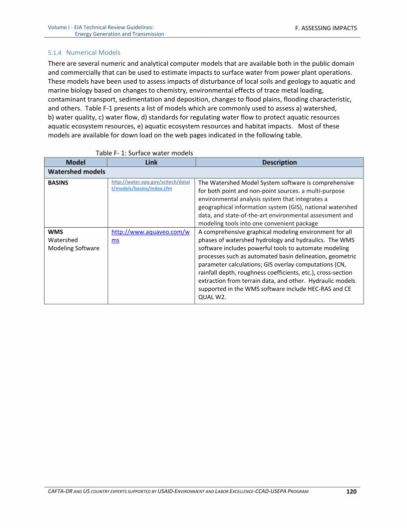
Volume I ‐ EIA Technical Review Guidelines: Energy Generation and Transmission
F. ASSESSING IMPACTS
CAFTA‐DR AND US COUNTRY EXPERTS SUPPORTED BY USAID‐ENVIRONMENT AND LABOR EXCELLENCE‐CCAD‐USEPA PROGRAM 120
5.1.4 Numerical Models
There are several numeric and analytical computer models that are available both in the public domain and commercially that can be used to estimate impacts to surface water from power plant operations. These models have been used to assess impacts of disturbance of local soils and geology to aquatic and marine biology based on changes to chemistry, environmental effects of trace metal loading, contaminant transport, sedimentation and deposition, changes to flood plains, flooding characteristic, and others. Table F‐1 presents a list of models which are commonly used to assess a) watershed, b) water quality, c) water flow, d) standards for regulating water flow to protect aquatic resources aquatic ecosystem resources, e) aquatic ecosystem resources and habitat impacts. Most of these models are available for down load on the web pages indicated in the following table.
Table F‐ 1: Surface water models
Model Link Description
Watershed models
BASINS http://water.epa.gov/scitech/datait/models/basins/index.cfm
The Watershed Model System software is comprehensive for both point and non‐point sources. a multi‐purpose environmental analysis system that integrates a geographical information system (GIS), national watershed data, and state‐of‐the‐art environmental assessment and modeling tools into one convenient package
WMS Watershed Modeling Software
http://www.aquaveo.com/wms
A comprehensive graphical modeling environment for all phases of watershed hydrology and hydraulics. The WMS software includes powerful tools to automate modeling processes such as automated basin delineation, geometric parameter calculations; GIS overlay computations (CN, rainfall depth, roughness coefficients, etc.), cross‐section extraction from terrain data, and other. Hydraulic models supported in the WMS software include HEC‐RAS and CE QUAL W2.
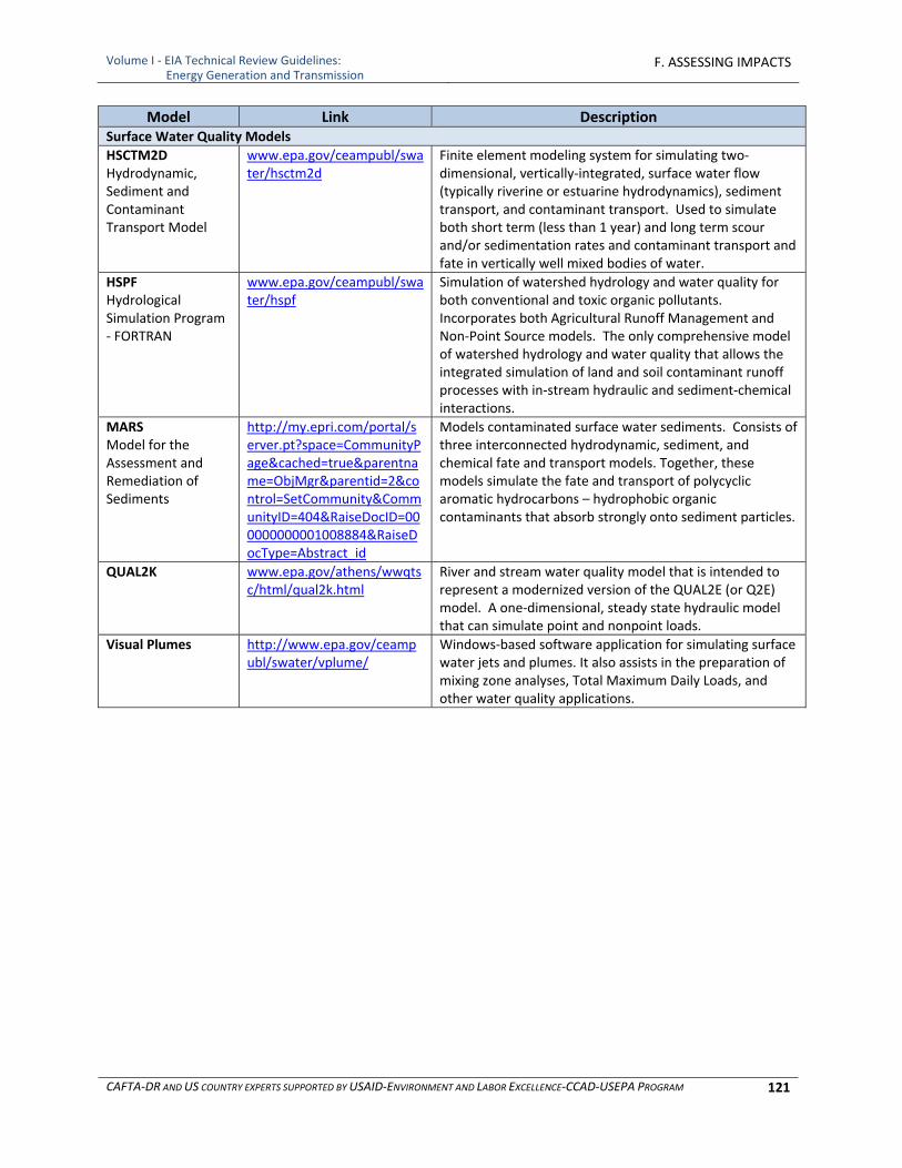
Volume I ‐ EIA Technical Review Guidelines: Energy Generation and Transmission
F. ASSESSING IMPACTS
CAFTA‐DR AND US COUNTRY EXPERTS SUPPORTED BY USAID‐ENVIRONMENT AND LABOR EXCELLENCE‐CCAD‐USEPA PROGRAM 121
Model Link Description Surface Water Quality Models
HSCTM2D Hydrodynamic, Sediment and Contaminant Transport Model
www.epa.gov/ceampubl/swater/hsctm2d
Finite element modeling system for simulating two‐dimensional, vertically‐integrated, surface water flow (typically riverine or estuarine hydrodynamics), sediment transport, and contaminant transport. Used to simulate both short term (less than 1 year) and long term scour and/or sedimentation rates and contaminant transport and fate in vertically well mixed bodies of water.
HSPF Hydrological Simulation Program ‐ FORTRAN
www.epa.gov/ceampubl/swater/hspf
Simulation of watershed hydrology and water quality for both conventional and toxic organic pollutants. Incorporates both Agricultural Runoff Management and Non‐Point Source models. The only comprehensive model of watershed hydrology and water quality that allows the integrated simulation of land and soil contaminant runoff processes with in‐stream hydraulic and sediment‐chemical interactions.
MARS Model for the Assessment and Remediation of Sediments
http://my.epri.com/portal/server.pt?space=CommunityPage&cached=true&parentname=ObjMgr&parentid=2&control=SetCommunity&CommunityID=404&RaiseDocID=000000000001008884&RaiseDocType=Abstract_id
Models contaminated surface water sediments. Consists of three interconnected hydrodynamic, sediment, and chemical fate and transport models. Together, these models simulate the fate and transport of polycyclic aromatic hydrocarbons – hydrophobic organic contaminants that absorb strongly onto sediment particles.
QUAL2K www.epa.gov/athens/wwqtsc/html/qual2k.html
River and stream water quality model that is intended to represent a modernized version of the QUAL2E (or Q2E) model. A one‐dimensional, steady state hydraulic model that can simulate point and nonpoint loads.
Visual Plumes http://www.epa.gov/ceampubl/swater/vplume/
Windows‐based software application for simulating surface water jets and plumes. It also assists in the preparation of mixing zone analyses, Total Maximum Daily Loads, and other water quality applications.
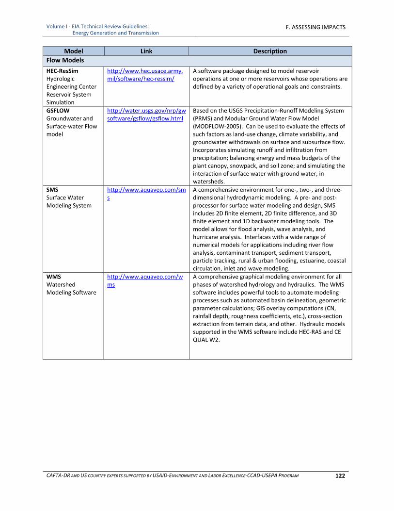
Volume I ‐ EIA Technical Review Guidelines: Energy Generation and Transmission
F. ASSESSING IMPACTS
CAFTA‐DR AND US COUNTRY EXPERTS SUPPORTED BY USAID‐ENVIRONMENT AND LABOR EXCELLENCE‐CCAD‐USEPA PROGRAM 122
Model Link Description
Flow Models
HEC‐ResSim Hydrologic Engineering Center Reservoir System Simulation
http://www.hec.usace.army.mil/software/hec‐ressim/
A software package designed to model reservoir operations at one or more reservoirs whose operations are defined by a variety of operational goals and constraints.
GSFLOW Groundwater and Surface‐water Flow model
http://water.usgs.gov/nrp/gwsoftware/gsflow/gsflow.html
Based on the USGS Precipitation‐Runoff Modeling System (PRMS) and Modular Ground Water Flow Model (MODFLOW‐2005). Can be used to evaluate the effects of such factors as land‐use change, climate variability, and groundwater withdrawals on surface and subsurface flow. Incorporates simulating runoff and infiltration from precipitation; balancing energy and mass budgets of the plant canopy, snowpack, and soil zone; and simulating the interaction of surface water with ground water, in watersheds.
SMS Surface Water Modeling System
http://www.aquaveo.com/sms
A comprehensive environment for one‐, two‐, and three‐dimensional hydrodynamic modeling. A pre‐ and post‐processor for surface water modeling and design, SMS includes 2D finite element, 2D finite difference, and 3D finite element and 1D backwater modeling tools. The model allows for flood analysis, wave analysis, and hurricane analysis. Interfaces with a wide range of numerical models for applications including river flow analysis, contaminant transport, sediment transport, particle tracking, rural & urban flooding, estuarine, coastal circulation, inlet and wave modeling.
WMS Watershed Modeling Software
http://www.aquaveo.com/wms
A comprehensive graphical modeling environment for all phases of watershed hydrology and hydraulics. The WMS software includes powerful tools to automate modeling processes such as automated basin delineation, geometric parameter calculations; GIS overlay computations (CN, rainfall depth, roughness coefficients, etc.), cross‐section extraction from terrain data, and other. Hydraulic models supported in the WMS software include HEC‐RAS and CE QUAL W2.
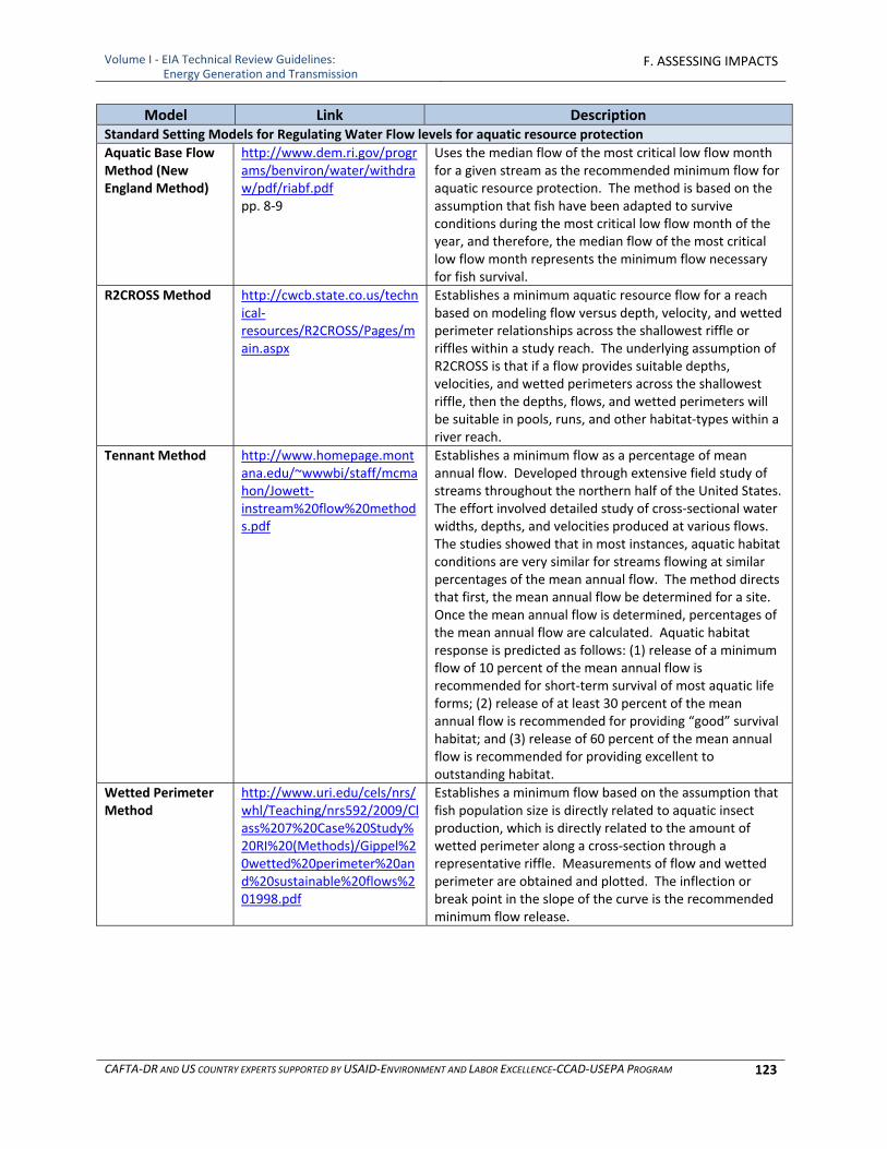
Volume I ‐ EIA Technical Review Guidelines: Energy Generation and Transmission
F. ASSESSING IMPACTS
CAFTA‐DR AND US COUNTRY EXPERTS SUPPORTED BY USAID‐ENVIRONMENT AND LABOR EXCELLENCE‐CCAD‐USEPA PROGRAM 123
Model Link Description Standard Setting Models for Regulating Water Flow levels for aquatic resource protection
Aquatic Base Flow Method (New England Method)
http://www.dem.ri.gov/programs/benviron/water/withdraw/pdf/riabf.pdf pp. 8‐9
Uses the median flow of the most critical low flow month for a given stream as the recommended minimum flow for aquatic resource protection. The method is based on the assumption that fish have been adapted to survive conditions during the most critical low flow month of the year, and therefore, the median flow of the most critical low flow month represents the minimum flow necessary for fish survival.
R2CROSS Method http://cwcb.state.co.us/technical‐resources/R2CROSS/Pages/main.aspx
Establishes a minimum aquatic resource flow for a reach based on modeling flow versus depth, velocity, and wetted perimeter relationships across the shallowest riffle or riffles within a study reach. The underlying assumption of R2CROSS is that if a flow provides suitable depths, velocities, and wetted perimeters across the shallowest riffle, then the depths, flows, and wetted perimeters will be suitable in pools, runs, and other habitat‐types within a river reach.
Tennant Method http://www.homepage.montana.edu/~wwwbi/staff/mcmahon/Jowett‐instream%20flow%20methods.pdf
Establishes a minimum flow as a percentage of mean annual flow. Developed through extensive field study of streams throughout the northern half of the United States. The effort involved detailed study of cross‐sectional water widths, depths, and velocities produced at various flows. The studies showed that in most instances, aquatic habitat conditions are very similar for streams flowing at similar percentages of the mean annual flow. The method directs that first, the mean annual flow be determined for a site. Once the mean annual flow is determined, percentages of the mean annual flow are calculated. Aquatic habitat response is predicted as follows: (1) release of a minimum flow of 10 percent of the mean annual flow is recommended for short‐term survival of most aquatic life forms; (2) release of at least 30 percent of the mean annual flow is recommended for providing “good” survival habitat; and (3) release of 60 percent of the mean annual flow is recommended for providing excellent to outstanding habitat.
Wetted Perimeter Method
http://www.uri.edu/cels/nrs/whl/Teaching/nrs592/2009/Class%207%20Case%20Study%20RI%20(Methods)/Gippel%20wetted%20perimeter%20and%20sustainable%20flows%201998.pdf
Establishes a minimum flow based on the assumption that fish population size is directly related to aquatic insect production, which is directly related to the amount of wetted perimeter along a cross‐section through a representative riffle. Measurements of flow and wetted perimeter are obtained and plotted. The inflection or break point in the slope of the curve is the recommended minimum flow release.
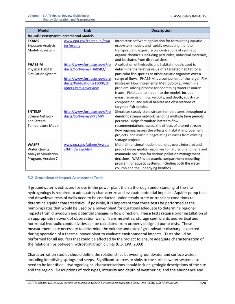
Volume I ‐ EIA Technical Review Guidelines: Energy Generation and Transmission
F. ASSESSING IMPACTS
CAFTA‐DR AND US COUNTRY EXPERTS SUPPORTED BY USAID‐ENVIRONMENT AND LABOR EXCELLENCE‐CCAD‐USEPA PROGRAM 124
Model Link Description
Aquatic ecosystem Incremental Models
EXAMS Exposure Analysis Modeling System
www.epa.gov/ceampubl/swater/exams
Interactive software application for formulating aquatic ecosystem models and rapidly evaluating the fate, transport, and exposure concentrations of synthetic organic chemicals including pesticides, industrial materials, and leachates from disposal sites.
PHABSIM Physical Habitat Simulation System
http://www.fort.usgs.gov/Products/Software/PHABSIM/ http://www.fort.usgs.gov/products/Publications/15000/chapter1.html#overview
A collection of hydraulic and habitat models used to determine the relative value of a targeted habitat for a particular fish species or other aquatic organism over a range of flows. PHABSIM is a component of the larger IFIM (Instream Flow Incremental Methodology), which is a problem‐solving process for addressing water resource issues. Field data to input into the models include measurements of flow, velocity, and depth; substrate composition; and visual habitat use observations of targeted fish species.
SNTEMP Stream Network and Stream Temperature Model
http://www.fort.usgs.gov/Products/Software/SNTEMP/
Simulates steady‐state stream temperatures throughout a dendritic stream network handling multiple time periods per year. Helps formulate instream flow recommendations, assess the effects of altered stream flow regimes, assess the effects of habitat improvement projects, and assist in negotiating releases from existing storage projects.
WASP7 Water Quality Analysis Simulation Program, Version 7
www.epa.gov/athens/wwqtsc/html/wasp.html
Multi‐dimensional model that helps users interpret and predict water quality responses to natural phenomena and manmade pollution for various pollution management decisions. WASP is a dynamic compartment‐modeling program for aquatic systems, including both the water column and the underlying benthos.
5.2 Groundwater Impact Assessment Tools
If groundwater is extracted for use in the power plant then a thorough understanding of the site hydrogeology is required to adequately characterize and evaluate potential impacts. Aquifer pump tests and drawdown tests of wells need to be conducted under steady‐state or transient conditions to determine aquifer characteristics. If possible, it is important that these tests be performed at the pumping rates that would be used by a power plant for durations adequate to determine regional impacts from drawdown and potential changes in flow direction. These tests require prior installation of an appropriate network of observation wells. Transmissivities, storage coefficients and vertical and horizontal hydraulic conductivities can be calculated from properly designed pump tests. These measurements are necessary to determine the volume and rate of groundwater discharge expected during operation of a thermal power plant to evaluate environmental impacts. Tests should be performed for all aquifers that could be affected by the project to ensure adequate characterization of the relationships between hydrostratigraphic units (U.S. EPA, 2003). Characterization studies should define the relationships between groundwater and surface water, including identifying springs and seeps. Significant sources or sinks to the surface water system also need to be identified. Hydrogeological characterizations should include geologic descriptions of the site and the region. Descriptions of rock types, intensity and depth of weathering, and the abundance and
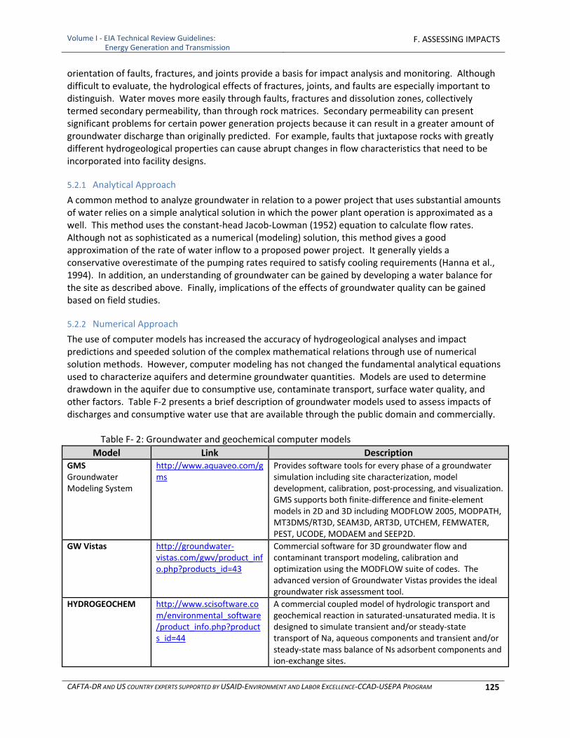
Volume I ‐ EIA Technical Review Guidelines: Energy Generation and Transmission
F. ASSESSING IMPACTS
CAFTA‐DR AND US COUNTRY EXPERTS SUPPORTED BY USAID‐ENVIRONMENT AND LABOR EXCELLENCE‐CCAD‐USEPA PROGRAM 125
orientation of faults, fractures, and joints provide a basis for impact analysis and monitoring. Although difficult to evaluate, the hydrological effects of fractures, joints, and faults are especially important to distinguish. Water moves more easily through faults, fractures and dissolution zones, collectively termed secondary permeability, than through rock matrices. Secondary permeability can present significant problems for certain power generation projects because it can result in a greater amount of groundwater discharge than originally predicted. For example, faults that juxtapose rocks with greatly different hydrogeological properties can cause abrupt changes in flow characteristics that need to be incorporated into facility designs.
5.2.1 Analytical Approach
A common method to analyze groundwater in relation to a power project that uses substantial amounts of water relies on a simple analytical solution in which the power plant operation is approximated as a well. This method uses the constant‐head Jacob‐Lowman (1952) equation to calculate flow rates. Although not as sophisticated as a numerical (modeling) solution, this method gives a good approximation of the rate of water inflow to a proposed power project. It generally yields a conservative overestimate of the pumping rates required to satisfy cooling requirements (Hanna et al., 1994). In addition, an understanding of groundwater can be gained by developing a water balance for the site as described above. Finally, implications of the effects of groundwater quality can be gained based on field studies.
5.2.2 Numerical Approach
The use of computer models has increased the accuracy of hydrogeological analyses and impact predictions and speeded solution of the complex mathematical relations through use of numerical solution methods. However, computer modeling has not changed the fundamental analytical equations used to characterize aquifers and determine groundwater quantities. Models are used to determine drawdown in the aquifer due to consumptive use, contaminate transport, surface water quality, and other factors. Table F‐2 presents a brief description of groundwater models used to assess impacts of discharges and consumptive water use that are available through the public domain and commercially.
Table F‐ 2: Groundwater and geochemical computer models
Model Link Description GMS Groundwater Modeling System
http://www.aquaveo.com/gms
Provides software tools for every phase of a groundwater simulation including site characterization, model development, calibration, post‐processing, and visualization. GMS supports both finite‐difference and finite‐element models in 2D and 3D including MODFLOW 2005, MODPATH, MT3DMS/RT3D, SEAM3D, ART3D, UTCHEM, FEMWATER, PEST, UCODE, MODAEM and SEEP2D.
GW Vistas http://groundwater‐vistas.com/gwv/product_info.php?products_id=43
Commercial software for 3D groundwater flow and contaminant transport modeling, calibration and optimization using the MODFLOW suite of codes. The advanced version of Groundwater Vistas provides the ideal groundwater risk assessment tool.
HYDROGEOCHEM http://www.scisoftware.com/environmental_software/product_info.php?products_id=44
A commercial coupled model of hydrologic transport and geochemical reaction in saturated‐unsaturated media. It is designed to simulate transient and/or steady‐state transport of Na, aqueous components and transient and/or steady‐state mass balance of Ns adsorbent components and ion‐exchange sites.
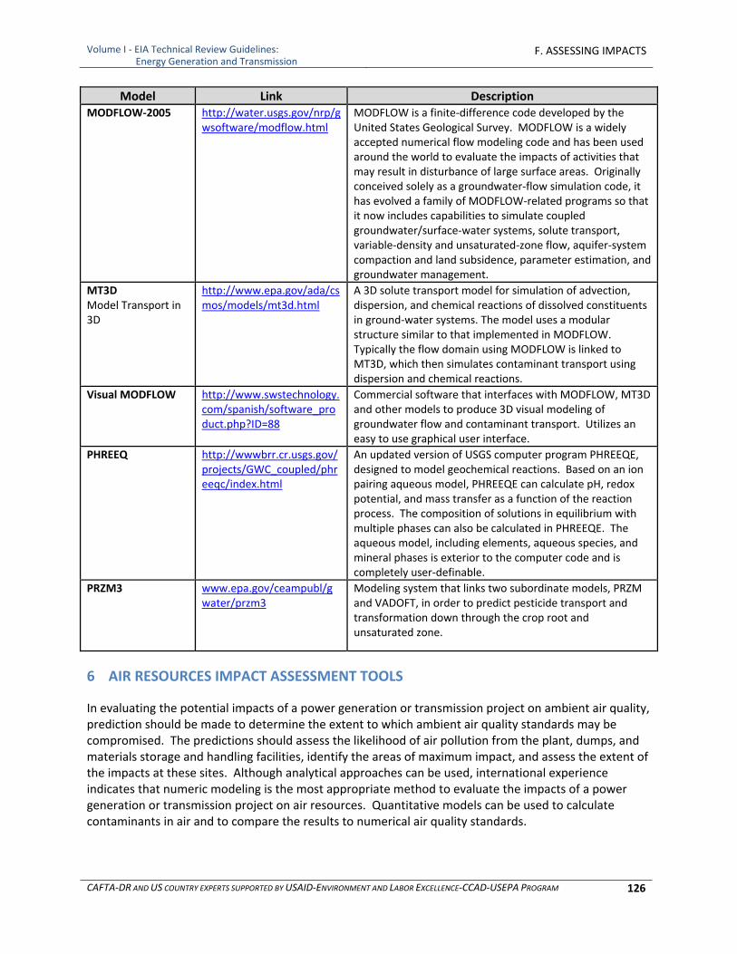
Volume I ‐ EIA Technical Review Guidelines: Energy Generation and Transmission
F. ASSESSING IMPACTS
CAFTA‐DR AND US COUNTRY EXPERTS SUPPORTED BY USAID‐ENVIRONMENT AND LABOR EXCELLENCE‐CCAD‐USEPA PROGRAM 126
Model Link Description MODFLOW‐2005 http://water.usgs.gov/nrp/g
wsoftware/modflow.html MODFLOW is a finite‐difference code developed by the United States Geological Survey. MODFLOW is a widely accepted numerical flow modeling code and has been used around the world to evaluate the impacts of activities that may result in disturbance of large surface areas. Originally conceived solely as a groundwater‐flow simulation code, it has evolved a family of MODFLOW‐related programs so that it now includes capabilities to simulate coupled groundwater/surface‐water systems, solute transport, variable‐density and unsaturated‐zone flow, aquifer‐system compaction and land subsidence, parameter estimation, and groundwater management.
MT3D Model Transport in 3D
http://www.epa.gov/ada/csmos/models/mt3d.html
A 3D solute transport model for simulation of advection, dispersion, and chemical reactions of dissolved constituents in ground‐water systems. The model uses a modular structure similar to that implemented in MODFLOW. Typically the flow domain using MODFLOW is linked to MT3D, which then simulates contaminant transport using dispersion and chemical reactions.
Visual MODFLOW http://www.swstechnology.com/spanish/software_product.php?ID=88
Commercial software that interfaces with MODFLOW, MT3D and other models to produce 3D visual modeling of groundwater flow and contaminant transport. Utilizes an easy to use graphical user interface.
PHREEQ http://wwwbrr.cr.usgs.gov/projects/GWC_coupled/phreeqc/index.html
An updated version of USGS computer program PHREEQE, designed to model geochemical reactions. Based on an ion pairing aqueous model, PHREEQE can calculate pH, redox potential, and mass transfer as a function of the reaction process. The composition of solutions in equilibrium with multiple phases can also be calculated in PHREEQE. The aqueous model, including elements, aqueous species, and mineral phases is exterior to the computer code and is completely user‐definable.
PRZM3 www.epa.gov/ceampubl/gwater/przm3
Modeling system that links two subordinate models, PRZM and VADOFT, in order to predict pesticide transport and transformation down through the crop root and unsaturated zone.
6 AIR RESOURCES IMPACT ASSESSMENT TOOLS
In evaluating the potential impacts of a power generation or transmission project on ambient air quality, prediction should be made to determine the extent to which ambient air quality standards may be compromised. The predictions should assess the likelihood of air pollution from the plant, dumps, and materials storage and handling facilities, identify the areas of maximum impact, and assess the extent of the impacts at these sites. Although analytical approaches can be used, international experience indicates that numeric modeling is the most appropriate method to evaluate the impacts of a power generation or transmission project on air resources. Quantitative models can be used to calculate contaminants in air and to compare the results to numerical air quality standards.
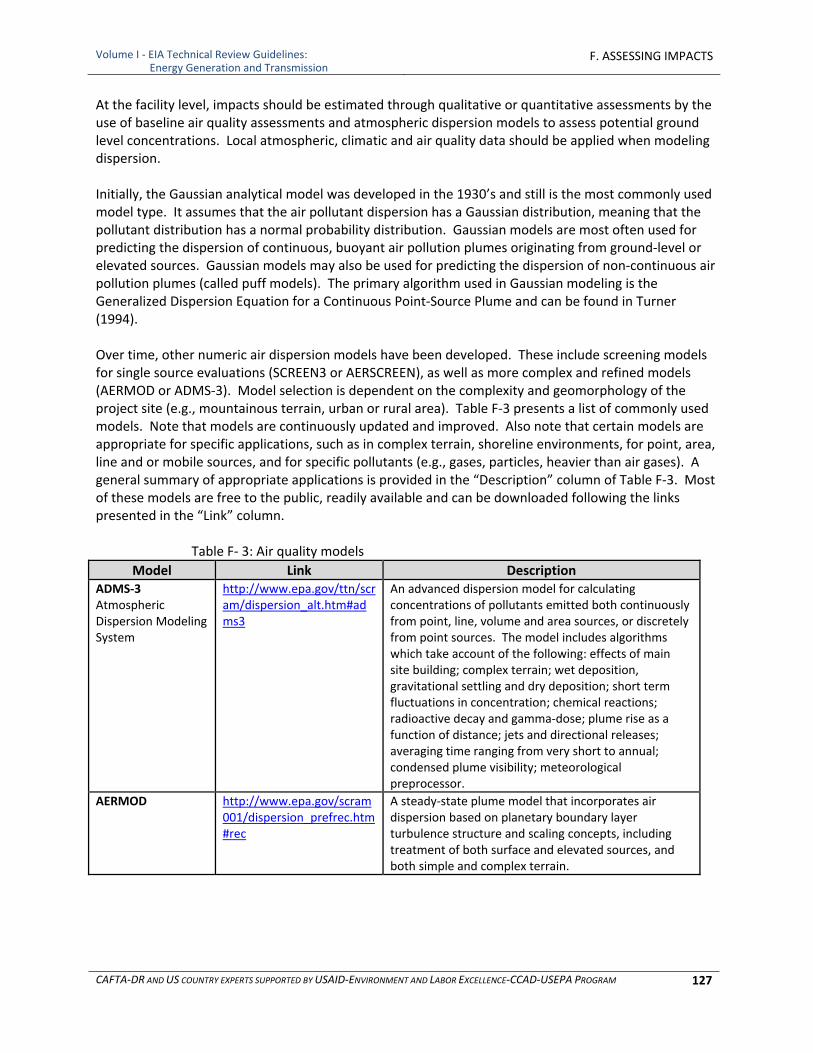
Volume I ‐ EIA Technical Review Guidelines: Energy Generation and Transmission
F. ASSESSING IMPACTS
CAFTA‐DR AND US COUNTRY EXPERTS SUPPORTED BY USAID‐ENVIRONMENT AND LABOR EXCELLENCE‐CCAD‐USEPA PROGRAM 127
At the facility level, impacts should be estimated through qualitative or quantitative assessments by the use of baseline air quality assessments and atmospheric dispersion models to assess potential ground level concentrations. Local atmospheric, climatic and air quality data should be applied when modeling dispersion. Initially, the Gaussian analytical model was developed in the 1930’s and still is the most commonly used model type. It assumes that the air pollutant dispersion has a Gaussian distribution, meaning that the pollutant distribution has a normal probability distribution. Gaussian models are most often used for predicting the dispersion of continuous, buoyant air pollution plumes originating from ground‐level or elevated sources. Gaussian models may also be used for predicting the dispersion of non‐continuous air pollution plumes (called puff models). The primary algorithm used in Gaussian modeling is the Generalized Dispersion Equation for a Continuous Point‐Source Plume and can be found in Turner (1994). Over time, other numeric air dispersion models have been developed. These include screening models for single source evaluations (SCREEN3 or AERSCREEN), as well as more complex and refined models (AERMOD or ADMS‐3). Model selection is dependent on the complexity and geomorphology of the project site (e.g., mountainous terrain, urban or rural area). Table F‐3 presents a list of commonly used models. Note that models are continuously updated and improved. Also note that certain models are appropriate for specific applications, such as in complex terrain, shoreline environments, for point, area, line and or mobile sources, and for specific pollutants (e.g., gases, particles, heavier than air gases). A general summary of appropriate applications is provided in the “Description” column of Table F‐3. Most of these models are free to the public, readily available and can be downloaded following the links presented in the “Link” column.
Table F‐ 3: Air quality models
Model Link Description ADMS‐3 Atmospheric Dispersion Modeling System
http://www.epa.gov/ttn/scram/dispersion_alt.htm#adms3
An advanced dispersion model for calculating concentrations of pollutants emitted both continuously from point, line, volume and area sources, or discretely from point sources. The model includes algorithms which take account of the following: effects of main site building; complex terrain; wet deposition, gravitational settling and dry deposition; short term fluctuations in concentration; chemical reactions; radioactive decay and gamma‐dose; plume rise as a function of distance; jets and directional releases; averaging time ranging from very short to annual; condensed plume visibility; meteorological preprocessor.
AERMOD http://www.epa.gov/scram001/dispersion_prefrec.htm#rec
A steady‐state plume model that incorporates air dispersion based on planetary boundary layer turbulence structure and scaling concepts, including treatment of both surface and elevated sources, and both simple and complex terrain.
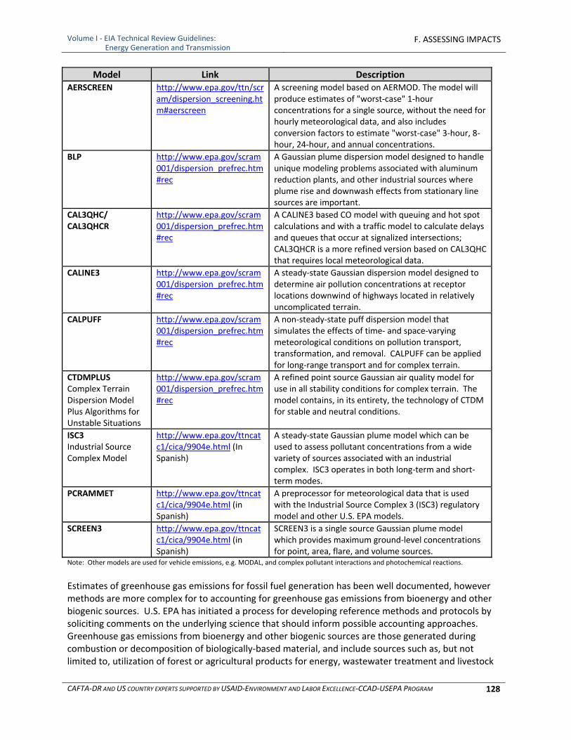
Volume I ‐ EIA Technical Review Guidelines: Energy Generation and Transmission
F. ASSESSING IMPACTS
CAFTA‐DR AND US COUNTRY EXPERTS SUPPORTED BY USAID‐ENVIRONMENT AND LABOR EXCELLENCE‐CCAD‐USEPA PROGRAM 128
Model Link Description AERSCREEN http://www.epa.gov/ttn/scr
am/dispersion_screening.htm#aerscreen
A screening model based on AERMOD. The model will produce estimates of "worst‐case" 1‐hour concentrations for a single source, without the need for hourly meteorological data, and also includes conversion factors to estimate "worst‐case" 3‐hour, 8‐hour, 24‐hour, and annual concentrations.
BLP http://www.epa.gov/scram001/dispersion_prefrec.htm#rec
A Gaussian plume dispersion model designed to handle unique modeling problems associated with aluminum reduction plants, and other industrial sources where plume rise and downwash effects from stationary line sources are important.
CAL3QHC/ CAL3QHCR
http://www.epa.gov/scram001/dispersion_prefrec.htm#rec
A CALINE3 based CO model with queuing and hot spot calculations and with a traffic model to calculate delays and queues that occur at signalized intersections; CAL3QHCR is a more refined version based on CAL3QHC that requires local meteorological data.
CALINE3 http://www.epa.gov/scram001/dispersion_prefrec.htm#rec
A steady‐state Gaussian dispersion model designed to determine air pollution concentrations at receptor locations downwind of highways located in relatively uncomplicated terrain.
CALPUFF http://www.epa.gov/scram001/dispersion_prefrec.htm#rec
A non‐steady‐state puff dispersion model that simulates the effects of time‐ and space‐varying meteorological conditions on pollution transport, transformation, and removal. CALPUFF can be applied for long‐range transport and for complex terrain.
CTDMPLUS Complex Terrain Dispersion Model Plus Algorithms for Unstable Situations
http://www.epa.gov/scram001/dispersion_prefrec.htm#rec
A refined point source Gaussian air quality model for use in all stability conditions for complex terrain. The model contains, in its entirety, the technology of CTDM for stable and neutral conditions.
ISC3 Industrial Source Complex Model
http://www.epa.gov/ttncatc1/cica/9904e.html (In Spanish)
A steady‐state Gaussian plume model which can be used to assess pollutant concentrations from a wide variety of sources associated with an industrial complex. ISC3 operates in both long‐term and short‐term modes.
PCRAMMET http://www.epa.gov/ttncatc1/cica/9904e.html (in Spanish)
A preprocessor for meteorological data that is used with the Industrial Source Complex 3 (ISC3) regulatory model and other U.S. EPA models.
SCREEN3 http://www.epa.gov/ttncatc1/cica/9904e.html (in Spanish)
SCREEN3 is a single source Gaussian plume model which provides maximum ground‐level concentrations for point, area, flare, and volume sources.
Note: Other models are used for vehicle emissions, e.g. MODAL, and complex pollutant interactions and photochemical reactions.
Estimates of greenhouse gas emissions for fossil fuel generation has been well documented, however methods are more complex for to accounting for greenhouse gas emissions from bioenergy and other biogenic sources. U.S. EPA has initiated a process for developing reference methods and protocols by soliciting comments on the underlying science that should inform possible accounting approaches. Greenhouse gas emissions from bioenergy and other biogenic sources are those generated during combustion or decomposition of biologically‐based material, and include sources such as, but not limited to, utilization of forest or agricultural products for energy, wastewater treatment and livestock
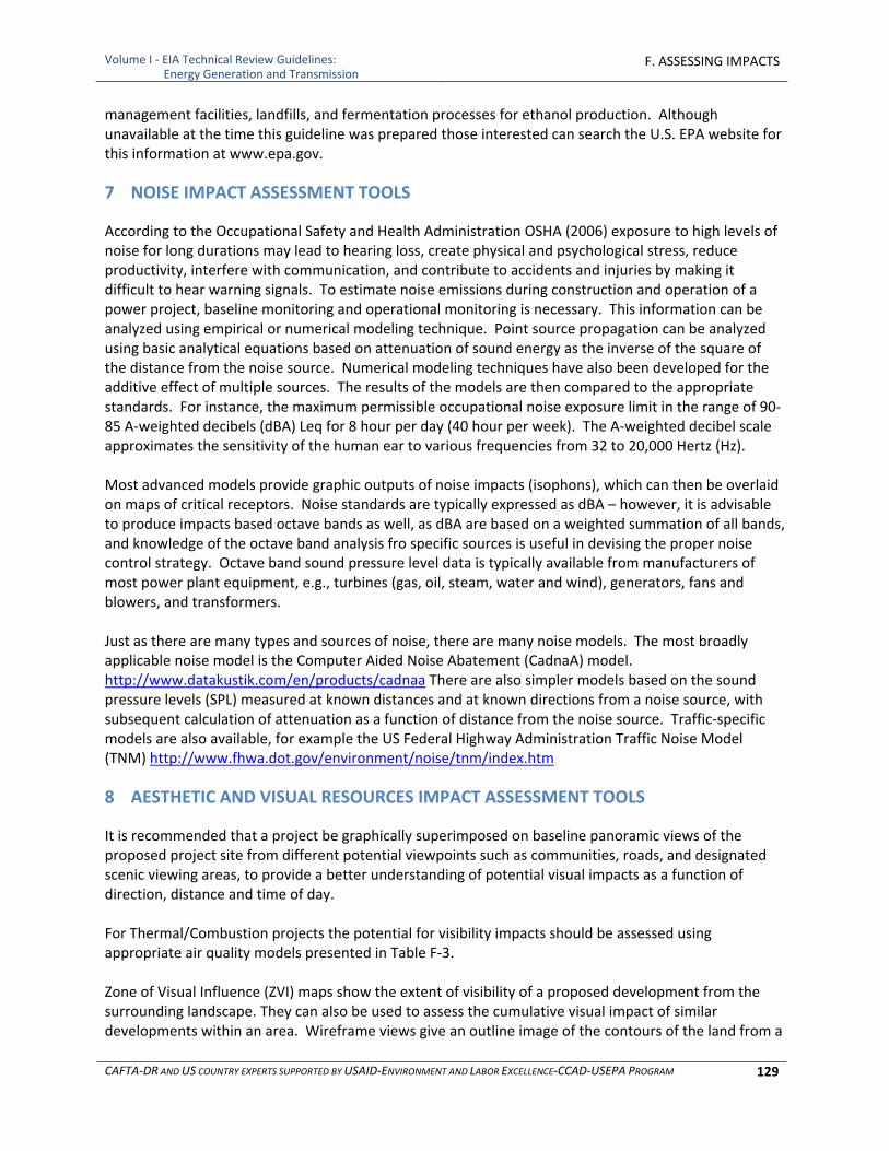
Volume I ‐ EIA Technical Review Guidelines: Energy Generation and Transmission
F. ASSESSING IMPACTS
CAFTA‐DR AND US COUNTRY EXPERTS SUPPORTED BY USAID‐ENVIRONMENT AND LABOR EXCELLENCE‐CCAD‐USEPA PROGRAM 129
management facilities, landfills, and fermentation processes for ethanol production. Although unavailable at the time this guideline was prepared those interested can search the U.S. EPA website for this information at www.epa.gov.
7 NOISE IMPACT ASSESSMENT TOOLS
According to the Occupational Safety and Health Administration OSHA (2006) exposure to high levels of noise for long durations may lead to hearing loss, create physical and psychological stress, reduce productivity, interfere with communication, and contribute to accidents and injuries by making it difficult to hear warning signals. To estimate noise emissions during construction and operation of a power project, baseline monitoring and operational monitoring is necessary. This information can be analyzed using empirical or numerical modeling technique. Point source propagation can be analyzed using basic analytical equations based on attenuation of sound energy as the inverse of the square of the distance from the noise source. Numerical modeling techniques have also been developed for the additive effect of multiple sources. The results of the models are then compared to the appropriate standards. For instance, the maximum permissible occupational noise exposure limit in the range of 90‐85 A‐weighted decibels (dBA) Leq for 8 hour per day (40 hour per week). The A‐weighted decibel scale approximates the sensitivity of the human ear to various frequencies from 32 to 20,000 Hertz (Hz). Most advanced models provide graphic outputs of noise impacts (isophons), which can then be overlaid on maps of critical receptors. Noise standards are typically expressed as dBA – however, it is advisable to produce impacts based octave bands as well, as dBA are based on a weighted summation of all bands, and knowledge of the octave band analysis fro specific sources is useful in devising the proper noise control strategy. Octave band sound pressure level data is typically available from manufacturers of most power plant equipment, e.g., turbines (gas, oil, steam, water and wind), generators, fans and blowers, and transformers. Just as there are many types and sources of noise, there are many noise models. The most broadly applicable noise model is the Computer Aided Noise Abatement (CadnaA) model. http://www.datakustik.com/en/products/cadnaa There are also simpler models based on the sound pressure levels (SPL) measured at known distances and at known directions from a noise source, with subsequent calculation of attenuation as a function of distance from the noise source. Traffic‐specific models are also available, for example the US Federal Highway Administration Traffic Noise Model (TNM) http://www.fhwa.dot.gov/environment/noise/tnm/index.htm
8 AESTHETIC AND VISUAL RESOURCES IMPACT ASSESSMENT TOOLS
It is recommended that a project be graphically superimposed on baseline panoramic views of the proposed project site from different potential viewpoints such as communities, roads, and designated scenic viewing areas, to provide a better understanding of potential visual impacts as a function of direction, distance and time of day. For Thermal/Combustion projects the potential for visibility impacts should be assessed using appropriate air quality models presented in Table F‐3. Zone of Visual Influence (ZVI) maps show the extent of visibility of a proposed development from the surrounding landscape. They can also be used to assess the cumulative visual impact of similar developments within an area. Wireframe views give an outline image of the contours of the land from a

Volume I ‐ EIA Technical Review Guidelines: Energy Generation and Transmission
F. ASSESSING IMPACTS
CAFTA‐DR AND US COUNTRY EXPERTS SUPPORTED BY USAID‐ENVIRONMENT AND LABOR EXCELLENCE‐CCAD‐USEPA PROGRAM 130
selected viewpoint. This gives a picture of the proposed development without obstruction from surrounding buildings and vegetation Photomontages are computer aided ‘photographs’ of a proposed development, showing a picture of how a development will appear after construction. An image of the proposed development is superimposed onto the photograph (http://www.fehilytimoney.ie/expertise‐services/visual‐impact‐assessment‐zvi‐maps‐wireframe‐views.html). The color photomontage is probably the most frequently used technique. Such a technique has the advantage of accurately portraying the landscape in a meaningful and easily recognizable form. In video montage techniques have been developed to demonstrate the important effects of movement. This is basically a video record of a site over which a computer‐generated animated photomontage is superimposed (Thomas, 1996.) Computer programs such as GIS, CAD, Autodesk 3DS Max, Adobe Photoshop, Adobe Illustrator software and other specialized software, used to model the visual impact of developments. These models are described in Table F‐4.
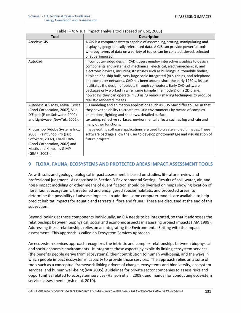
Volume I ‐ EIA Technical Review Guidelines: Energy Generation and Transmission
F. ASSESSING IMPACTS
CAFTA‐DR AND US COUNTRY EXPERTS SUPPORTED BY USAID‐ENVIRONMENT AND LABOR EXCELLENCE‐CCAD‐USEPA PROGRAM 131
Table F‐ 4: Visual impact analysis tools (based on Cox, 2003)
Tool Description ArcView GIS A GIS is a computer system capable of assembling, storing, manipulating and
displaying geographically referenced data. A GIS can provide powerful tools whereby layers of data on a variety of topics can be collated, sieved, selected or superimposed.
AutoCad In computer‐aided design (CAD), users employ interactive graphics to designcomponents and systems of mechanical, electrical, electromechanical, and electronic devices, including structures such as buildings, automobile bodies, airplane and ship hulls, very large‐scale integrated (VLSI) chips, and telephone and computer networks. CAD has been around since the early 1960’s, its use facilitates the design of objects through computers. Early CAD software packages only worked in wire frame (simple line models) on a 2D plane, nowadays they can operate in 3D using various shading techniques to produce realistic rendered images.
Autodest 3DS Max, Maya, Bryce (Corel Corporation, 2002), Vue D’Esprit (E‐on Software, 2002) and Lightwave (NewTek, 2002),
3D modeling and animation applications such as 3DS Max differ to CAD in that they have the ability to create realistic environments by means of complex animations, lighting and shadows, detailed surface texturing, reflective surfaces, environmental effects such as fog and rain and many other functions.
Photoshop (Adobe Systems Inc., 2003), Paint Shop Pro (Jasc Software, 2002), CorelDRAW (Corel Corporation, 2002) and Mattis and Kimball’s GIMP (GIMP, 2002),
Image editing software applications are used to create and edit images. These software package allow the user to develop photomontage and visualization of future projects.
9 FLORA, FAUNA, ECOSYSTEMS AND PROTECTED AREAS IMPACT ASSESSMENT TOOLS
As with soils and geology, biological impact assessment is based on studies, literature review and professional judgment. As described in Section D Environmental Setting. Results of soil, water, air, and noise impact modeling or other means of quantification should be overlaid on maps showing location of flora, fauna, ecosystems, threatened and endangered species habitats, and protected areas, to determine the possibility of adverse impacts. In addition, some computer models are available to help predict habitat impacts for aquatic and terrestrial flora and fauna. These are discussed at the end of this subsection. Beyond looking at these components individually, an EIA needs to be integrated, so that it addresses the relationships between biophysical, social and economic aspects in assessing project impacts (IAIA 1999). Addressing these relationships relies on an integrating the Environmental Setting with the impact assessment. This approach is called an Ecosystem Services Approach. An ecosystem services approach recognizes the intrinsic and complex relationships between biophysical and socio‐economic environments. It integrates these aspects by explicitly linking ecosystem services (the benefits people derive from ecosystems), their contribution to human well‐being, and the ways in which people impact ecosystems’ capacity to provide those services. The approach relies on a suite of tools such as a conceptual framework linking drivers of change, ecosystems and biodiversity, ecosystem services, and human well‐being (MA 2005); guidelines for private sector companies to assess risks and opportunities related to ecosystem services (Hanson et al. 2008), and manual for conducting ecosystem services assessments (Ash et al. 2010).
Volume I ‐ EIA Technical Review Guidelines: Energy Generation and Transmission
F. ASSESSING IMPACTS
CAFTA‐DR AND US COUNTRY EXPERTS SUPPORTED BY USAID‐ENVIRONMENT AND LABOR EXCELLENCE‐CCAD‐USEPA PROGRAM 132
In the context of environmental impact assessments, the ecosystem services approach provides a more systematic and integrated assessment of project impacts and dependencies on ecosystem services and the consequence for the people who benefit from these services. It helps EIA practitioners to go beyond biodiversity and ecosystems to identify and understand the ways natural and human environment interrelates. This holistic understanding, from description of the Environmental Setting to the impact assessment, will lead the EIA practitioner through a new set of questions organized around the conceptual framework shown below:
What are the ecosystem services important for local communities? ○ Which services will the project potentially impact in a significant way? ○ How does the impact on one ecosystem service affect the supply and use of other
ecosystem services?
What is the underlying level of biodiversity and the current capacity of the ecosystems to continue to provide ecosystem services?
What are the consequences of these ecosystem service impacts on human well‐being, for example what are the effects on livelihoods, income, and security?
What are the direct and indirect drivers of ecosystem change affecting the supply and use of ecosystem services? How will the project contribute to these direct and indirect drivers of change?
Systematically examining all the boxes in the framework presented in Figure F‐3 carries the following promises:
Since ecosystem services by definition are linked to different beneficiaries, any ecosystem service changes can then be explicitly translated into a gain or loss of human well‐being.
It will highlight the impact on all important ecosystem services provided by the area such as erosion control, pollination, water regulation, and pollutant removal.
It will ensure that the EIA accounts for the effects of the project on existing direct and indirect drivers of ecosystem change that in turn could impact the ecosystem services provided by the area.
It will improve the project’s management of risks and opportunities arising from ecosystem services.
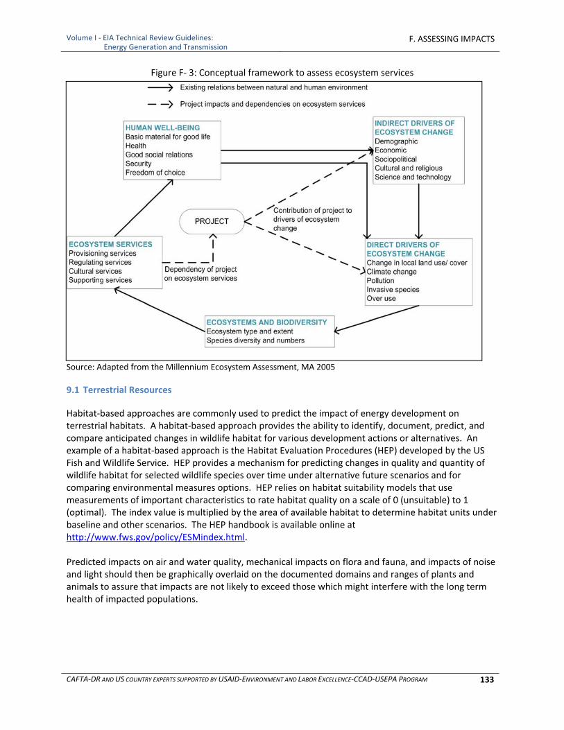
Volume I ‐ EIA Technical Review Guidelines: Energy Generation and Transmission
F. ASSESSING IMPACTS
CAFTA‐DR AND US COUNTRY EXPERTS SUPPORTED BY USAID‐ENVIRONMENT AND LABOR EXCELLENCE‐CCAD‐USEPA PROGRAM 133
Figure F‐ 3: Conceptual framework to assess ecosystem services
Source: Adapted from the Millennium Ecosystem Assessment, MA 2005
9.1 Terrestrial Resources
Habitat‐based approaches are commonly used to predict the impact of energy development on terrestrial habitats. A habitat‐based approach provides the ability to identify, document, predict, and compare anticipated changes in wildlife habitat for various development actions or alternatives. An example of a habitat‐based approach is the Habitat Evaluation Procedures (HEP) developed by the US Fish and Wildlife Service. HEP provides a mechanism for predicting changes in quality and quantity of wildlife habitat for selected wildlife species over time under alternative future scenarios and for comparing environmental measures options. HEP relies on habitat suitability models that use measurements of important characteristics to rate habitat quality on a scale of 0 (unsuitable) to 1 (optimal). The index value is multiplied by the area of available habitat to determine habitat units under baseline and other scenarios. The HEP handbook is available online at http://www.fws.gov/policy/ESMindex.html. Predicted impacts on air and water quality, mechanical impacts on flora and fauna, and impacts of noise and light should then be graphically overlaid on the documented domains and ranges of plants and animals to assure that impacts are not likely to exceed those which might interfere with the long term health of impacted populations.
Volume I ‐ EIA Technical Review Guidelines: Energy Generation and Transmission
F. ASSESSING IMPACTS
CAFTA‐DR AND US COUNTRY EXPERTS SUPPORTED BY USAID‐ENVIRONMENT AND LABOR EXCELLENCE‐CCAD‐USEPA PROGRAM 134
9.2 Aquatic Resources
Development of analytical models for assessment of aquatic resource impacts has primarily been focused toward establishing relationships between river flow and fish habitat quantity. Flow versus fish habitat models have generally been applied in situations of proposals for seasonal water storage and release associated with flood control or hydroelectric operation, and water diversions for irrigation, hydroelectric generation, and other water uses. The models generally come in two types: incremental and standard setting. Incremental models predict a range of conditions for a range of inputs. Incremental models tend to be site‐specific and of relatively high effort and cost to calibrate. They are analogous to the water quality models presented in Table F‐1. Standard setting models follow a fixed rule to address a defined question (e.g., How much base flow is required to maintain an aquatic ecosystem?) and therefore provide a single answer or “standard.” Standard setting models tend to be relatively generic (i.e., not site‐specific) and quick, and require low effort and cost. Table F‐1 includes the most commonly used analytical models used in assessment of aquatic resource impacts.
10 SOCIO‐ECONOMIC‐CULTURAL IMPACT ASSESSMENT TOOLS
10.1 Socio‐Economic Conditions, Infrastructure and Land Use
When an activity, such as development or expansion of a power project, or extension or upgrading of power transmission, is expected to accelerate social change at the local level, it is necessary to have detailed (sometimes household level) socio‐economic and cultural data from the directly affected communities for the baseline, and to develop trend data to assess whether potential impacts will continue or alter those trends in a significant way. Social impacts cannot usually be assessed through secondary data on infrastructure and social services. The results from detailed family level surveys, focus group discussions and key informant interviews, participant observation, stakeholder consultations, secondary data, and other direct data collection methods should be analyzed carefully (Joyce, 2001). As data are collected, trends based on gender, age groups, economic status, proximity to the projects should be analyzed. This analysis can be accomplished using statistical models or, as what has been found more recently to be effective, the use of Geographical Information Systems (GIS). According to Joyce et. al. (2001), the problem with using a strictly qualitative approach has issues:
There is a greater difficulty of predicting social behavior and response as compared to impacts on the biophysical or biological elements, such as water or animals.
The fact that social impacts are as much to do with the perceptions people or groups have about an activity as they are to do with the actual facts and substantive reality of a situation, and
The fabric of social interactions and social well‐being (today being recognized and labeled as “social capital”, which are in the end where many social impacts take place, can only be measured or evaluated through qualitative and participatory processes.
Volume I ‐ EIA Technical Review Guidelines: Energy Generation and Transmission
F. ASSESSING IMPACTS
CAFTA‐DR AND US COUNTRY EXPERTS SUPPORTED BY USAID‐ENVIRONMENT AND LABOR EXCELLENCE‐CCAD‐USEPA PROGRAM 135
As the causation gets more distant, it is less clear how directly responsible a given project or activity is for that impact and required environmental measures, and less clear how effective environmental measures taken by one player would be.
Again, according to Joyce, the measure of significance is the most difficult/critical part of socioeconomic impact assessment. Impacts should be described in terms of the level of intensity of an impact, the directionality (positive or negative), the duration, and its geographic extension. Significance is necessarily defined using professional judgment. Towards this end, categories of impacts are defined and a determination can be made as to what constitutes a short, medium and long term impact, and the reasons for the designation. This is where participation by locals becomes important in determining what is significant to them. Based on the significance of the impact(s) conclusions can be drawn and environmental measures can be designed. Other socioeconomic impacts which should be assessed include:
Land Use ‐ A power project or transmission corridor if not restored properly can change the land use of an area forever. To understand the impacts of power and transmission projects on land use, it is important to be able to visualize and calculate potential changes which may occur. This can be done by developing maps which show pre‐construction, operational and post‐closure land use. In many countries, GIS is used extensively for this purpose. GIS captures, stores, analyzes, manages, and presents data that is linked to location. GIS applications are tools that allow users to create interactive queries (user created searches), analyze spatial information, edit data, maps, and present the results of all these operations. A GIS includes mapping software and its application with remote sensing, land surveying, aerial photography, mathematics, photogrammetry, geography, and other tools.
Population and Housing ‐ The key to understanding the potential impact to the local population and housing is having a good understanding the work force required for the operation. Simple calculations can then be made to determine changes in demographics over the life of the project.
Infrastructure Capacity ‐ Simple calculations comparing demands on roads, hospitals, wastewater treatment, water supply and waste management against capacity. However, these calculations should take into account direct demands from the project for every phase of the project including construction, operation and closure, demands from anticipated induced growth as an indirect impact of the proposed project and demands into the future in the absence of the project.
Employment ‐ Again having a good understanding of the work force required for each phase (construction, operation and closure) of a power or transmission line project is required to determine what additional labor may be required for schools, hospitals, support industries, etc.
Transportation ‐ Transportation studies are required to determine impacts on traffic and roads due to commuting and the hauling of construction materials to the project site, delivery of fuel and removal of wastes if by rail, water or road, and increases in traffic associated with the work force servicing the project and providing support to that work force.
10.2 Cultural, Archeological, Ceremonial and Historic Resources Impact Assessment Tools
Impacts are usually defined as direct or indirect alterations to characteristics of a cultural archeological, ceremonial or historic site or traditional use of a resource. Effects are adverse when the integrity is affected or the quality diminished. Impact assessment begins with overlaying all project activities on the
Volume I ‐ EIA Technical Review Guidelines: Energy Generation and Transmission
F. ASSESSING IMPACTS
CAFTA‐DR AND US COUNTRY EXPERTS SUPPORTED BY USAID‐ENVIRONMENT AND LABOR EXCELLENCE‐CCAD‐USEPA PROGRAM 136
map of cultural archeological, ceremonial or historic site sites developed for the Environmental Setting, to identify all sites that may be directly impacted. In addition noise, vibration and visibility (of and from the sites) impacts need to be estimated, using the results of the noise, vibration and visibility assessments discussed above. Impacts to historical and archeological sites and cultural resources are evaluated with respect to their magnitude and significance. For cultural resources, it is important to consider impacts that may affect the transmission and retention of local values. These potential impacts to the transmission and retention of local values may be caused by impacts to plants, animals, fish, geology and water resources that may be used for cultural purposes by certain populations for traditional purposes, as well as visual impacts.
10.3 Assessing Disproportionate Environmental Impacts on Vulnerable Populations
Concerns are introduced in Chapter E section 4.5 of potential disproportionate high and adverse effects on certain populations, typically indigenous, minority and/or low income populations. Economic effects and cultural impacts are analyzed as part of the socioeconomic assessment and would include topics such as employment, revenue, economic development, etc. Environmental impacts are addressed in the environmental sections of the EIA. In the Impacts section of an EIA, the impacts that would most affect this population are acknowledged. Generally, adverse impacts are more intense for vulnerable populations, and the economic effects are usually greater. There are two types of sources of what are considered specialized impacts on vulnerable populations, i.e. “environmental justice” impacts. The first type of impact derives from the differences in life style that might typically be found among indigenous peoples and minority groups. For example, these groups might rely more heavily on the affected environment for sustenance or have greater access to the environment which may increase their exposure to harmful substances where those are identified in the environmental impact assessment. Another context in which the environmental justice analysis may be appropriate is to address minority and low income populations whose life styles or low income status may make them more vulnerable to adverse impacts. If they start with poor health or poor access to medical care, the impacts of adverse environmental impacts may fall more heavily on them. Often these populations live in locations in which many polluting sources may be co‐located. They may lack the language or political access to represent their interests before the government. These populations are generally less resilient than the larger population’s in the surrounding environment because of their economic circumstances in their ability to mitigate adverse impacts using their own resources.
10.4 Health and Safety Impact Assessment Tools
Power plant construction and operation and transmission line installation and maintenance always pose an inherent risk to human health and safety. Analysis of the impacts is accomplished by inventorying the opportunities for:
Exposure to dust, noise, and chemicals
Handling of chemicals
Accidents while working with heavy or other equipment
Exposure to high pressure liquids or gases
Exposure to high voltage transformers and transmission lines
Failure of water retention structures and potential impacts on downstream life and property

Volume I ‐ EIA Technical Review Guidelines: Energy Generation and Transmission
F. ASSESSING IMPACTS
CAFTA‐DR AND US COUNTRY EXPERTS SUPPORTED BY USAID‐ENVIRONMENT AND LABOR EXCELLENCE‐CCAD‐USEPA PROGRAM 137
This assessment may take in to account proposed measures to reduce risks, but if that is done then the measures used to minimize or eliminate risk should be included in the environmental measures section in terms which reflect commitment of the project operator to carry them out effectively. Impacts on health and safety are identified in regulations that are in place to minimize the effects to workers and people in surrounding areas. Laws and regulations are a large factor in determining the policies and procedures that will be implemented to ensure that risk is minimized and that the project is in compliance with applicable requirements. Other aspects that may be associated with power and transmission projects, depending on project type and location, and which may impact human health and safety include:
Blasting ‐ Impacts from blasting should be inventoried and addressed. Some of the potential impacts result from noise, vibration, dust, and explosives handling and storage.
Transportation ‐ Impacts from transportation may result from vehicular or aircraft accidents.
Natural Hazards ‐ Natural hazards that should be addressed include working in extreme temperatures, flash flooding and dangerous wildlife such as poisonous snakes.
Solid, Liquid and Hazardous Waste – Solid, liquid and hazardous waste may also pose hazards to health and safety.
Even with regulations, policies, procedures, reporting, training and monitoring in place, accidents may happen. Having emergency response plans in place that address accidents and catastrophic releases will reduce the area and seriousness of impacts.
11 CUMULATIVE IMPACTS ASSESSMENT METHODS
Predictive tools and methods used for cumulative impact assessment are similar to those used to predict impacts generally, but the input parameters are different in that they include all past, present and predicted future actions affecting the resource. The analysis is focused and applied where it is most useful through a process of identifying which resources may be significantly affected and applying more detailed assessments to those resources for which cumulative impact assessment is most important. Three general steps, are recommended to ensure the proper assessment of cumulative impacts.
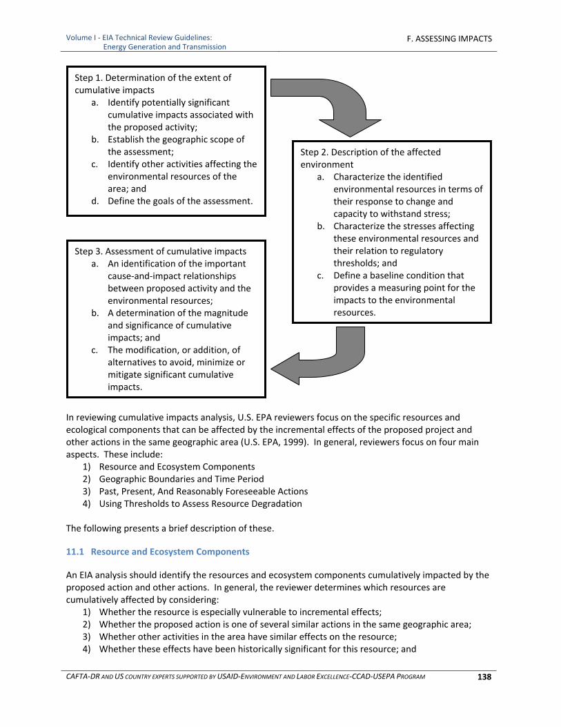
Volume I ‐ EIA Technical Review Guidelines: Energy Generation and Transmission
F. ASSESSING IMPACTS
CAFTA‐DR AND US COUNTRY EXPERTS SUPPORTED BY USAID‐ENVIRONMENT AND LABOR EXCELLENCE‐CCAD‐USEPA PROGRAM 138
In reviewing cumulative impacts analysis, U.S. EPA reviewers focus on the specific resources and ecological components that can be affected by the incremental effects of the proposed project and other actions in the same geographic area (U.S. EPA, 1999). In general, reviewers focus on four main aspects. These include:
1) Resource and Ecosystem Components 2) Geographic Boundaries and Time Period 3) Past, Present, And Reasonably Foreseeable Actions 4) Using Thresholds to Assess Resource Degradation
The following presents a brief description of these.
11.1 Resource and Ecosystem Components
An EIA analysis should identify the resources and ecosystem components cumulatively impacted by the proposed action and other actions. In general, the reviewer determines which resources are cumulatively affected by considering:
1) Whether the resource is especially vulnerable to incremental effects; 2) Whether the proposed action is one of several similar actions in the same geographic area; 3) Whether other activities in the area have similar effects on the resource; 4) Whether these effects have been historically significant for this resource; and
Step 1. Determination of the extent of cumulative impacts
a. Identify potentially significant cumulative impacts associated with the proposed activity;
b. Establish the geographic scope of the assessment;
c. Identify other activities affecting the environmental resources of the area; and
d. Define the goals of the assessment.
Step 2. Description of the affected environment
a. Characterize the identified environmental resources in terms of their response to change and capacity to withstand stress;
b. Characterize the stresses affecting these environmental resources and their relation to regulatory thresholds; and
c. Define a baseline condition that provides a measuring point for the impacts to the environmental resources.
Step 3. Assessment of cumulative impacts a. An identification of the important
cause‐and‐impact relationships between proposed activity and the environmental resources;
b. A determination of the magnitude and significance of cumulative impacts; and
c. The modification, or addition, of alternatives to avoid, minimize or mitigate significant cumulative impacts.

Volume I ‐ EIA Technical Review Guidelines: Energy Generation and Transmission
F. ASSESSING IMPACTS
CAFTA‐DR AND US COUNTRY EXPERTS SUPPORTED BY USAID‐ENVIRONMENT AND LABOR EXCELLENCE‐CCAD‐USEPA PROGRAM 139
5) Whether other analyses in the area have identified a cumulative effects concern. The analysis should be expanded for only those resources that are significantly affected. In similar fashion, ecosystem components should be considered when they are significantly affected by cumulative impacts. The measure of cumulative effects is any change to the function of these ecosystem components. Therefore, EIA documents should consider only a limited number of resources that may be potentially affected by cumulative impacts. To ensure the inclusion of the resources that may be most susceptible, cumulative impacts can be anticipated by considering where cumulative effects are likely to occur and what actions would most likely produce cumulative effects. The EIA document should identify which resources or ecosystem components of concern might be affected by the proposed action or its alternatives within the project area. Once these resources have been identified, consideration should be given to the ecological requirements needed to sustain the resources. It is important that the EIA document consider these broader ecological requirements when assessing how the project and other actions may cumulatively affect the resources of concern. Often these ecological requirements may extend beyond the boundaries of the project area, but reasonable limits should be made to the scope of the analysis.
11.2 Geographic Boundaries and Time Period
With the resources identified, the EIA will need to identify the appropriate geographic and temporal scope of analysis for those resources. Without spatial boundaries (geographic), a cumulative effects assessment would be global, and while this may be appropriate for some issues such as global climate change, it is not appropriate for most other issues. The EIA should briefly describe how those resources might be cumulatively affected and explain the geographic scope of analysis. To determine spatial boundaries, consideration should be given to the distance the effect can travel in the context of resource effects from other activities that might affect a wide area. Specifically, the EIA should:
Describe how it determined the area(s) that will be affected by the proposed action (impact zone)
List the cumulative effects resources within that area that could be affected by the proposed action
Determine the geographic area outside of the impact zone that is occupied by those resources
Consider the management plans and jurisdictions of other agencies for the cumulatively affected resource
The EIA should:
Discuss the location of other projects and major developmental activities within the area
Include a schematic diagram of these developments and/or list them in a table
Briefly describe how the proposed project interacts, affects, or is affected by, these other resource developments
The length of discussion should reflect the significance of the interaction. Include details of the effects of these interactions in the Anticipated Impacts section.
Volume I ‐ EIA Technical Review Guidelines: Energy Generation and Transmission
F. ASSESSING IMPACTS
CAFTA‐DR AND US COUNTRY EXPERTS SUPPORTED BY USAID‐ENVIRONMENT AND LABOR EXCELLENCE‐CCAD‐USEPA PROGRAM 140
11.3 Describing the Condition of the Environment
The EIA analysis should establish the magnitude and significance of cumulative impacts by comparing the environment in its naturally occurring state with the expected impacts of the proposed action when combined with the impacts of other actions. Use of a "benchmark" or "baseline" for purposes of comparing conditions is an essential part of any environmental analysis. If it is not possible to establish the "naturally occurring" condition, a description of a modified but ecologically sustainable condition can be used in the analysis. In this context, ecologically sustainable means the system supports biological processes, maintains its level of biological productivity, functions with minimal external management, and repairs itself when stressed. While a description of past environmental conditions is usually included in EIA documents, it is seldom used to fully assess how the system has changed from previous conditions. The comparison of the environmental condition and expected environmental impacts can be incorporated into the Anticipated Impacts section of EIA documents. EIA reviewers should determine whether the EIA analysis accurately depicts the condition of the environment used to assess cumulative impacts. In addition, reviewers should determine whether EIA documents incorporate the cumulative effects of all relevant past activities into the Anticipated Impacts section. For the evaluation of the environmental consequences to be useful, it is important that the analysis also incorporate the degree that the existing ecosystem will change over time under each alternative. Different methods of depicting the environmental condition are acceptable. The condition of the environment should, however, address one or more of the following:
1) How the affected environment functions naturally and whether it has been significantly degraded;
2) The specific characteristics of the affected environment and the extent of change, if any, that has occurred in that environment; and
3) A description of the natural condition of the environment or, if that is not available, some modified, but ecologically sustainable, condition to serve as a benchmark.
Two practical methods for depicting the environmental condition include use of the no‐action alternative and an environmental reference point. Historically, the no‐action alternative (as reflecting existing conditions) has usually been used as a benchmark for comparing the proposed action and alternatives to existing conditions. The no‐action alternative can be an effective benchmark if it incorporates the cumulative effects of past activities and accurately depicts the condition of the environment. Another approach for describing the environmental condition is to use an environmental reference point that would be incorporated into the Anticipated Impacts section of the document. The natural condition of the ecosystem, or some modified but sustainable ecosystem condition, can be described as the environmental reference point. In analyzing environmental impacts, this environmental reference point would not necessarily be an alternative. Instead, it would serve as a benchmark in assessing the environmental impacts associated with each of the alternatives. Specifically, the analysis would evaluate the degree of degradation from the environmental reference point (i.e., natural ecosystem condition) that has resulted from past actions. Then the relative difference among alternatives would be determined for not only changes compared to the existing condition but also changes critical to maintaining or restoring the desired, sustainable condition.
Volume I ‐ EIA Technical Review Guidelines: Energy Generation and Transmission
F. ASSESSING IMPACTS
CAFTA‐DR AND US COUNTRY EXPERTS SUPPORTED BY USAID‐ENVIRONMENT AND LABOR EXCELLENCE‐CCAD‐USEPA PROGRAM 141
Determining what environmental condition to use in the assessment may not be immediately clear. Choosing and describing a condition should be based on the specific characteristics of the area. In addition, the choice of condition can be constrained by limited resources and information. For these reasons, the environmental condition described by the environmental reference point or no‐action alternative should be constructed on a case‐by‐case basis so that it represents an ecosystem able to sustain itself in the larger context of activities in the region. In this respect, there is no predetermined point in time that automatically should represent the environmental condition. In addition, it may not be practical to use a pristine condition in many situations. Depending on whether the information is reasonably obtainable, the environmental condition chosen may be a pristine environment, or at the very least, minimally functioning ecosystems that will not further degrade. The use of the environmental condition to compare alternatives is not an academic exercise, but one that can most effectively modify alternatives and help decision making. Examples of conditions might include before project, before "substantial" development, or a reference ecosystem that is comparable to the project area. Selecting the best environmental condition for comparative purposes can be based on the following:
1) Consider what the environment would look like or how it would behave without serious human alteration;
2) Factor in the dynamic nature of the environment; 3) Define the distinct characteristics and attributes of the environment that best represent that
particular type of environment (focus on characteristics and attributes that have to do with function); and
4) Use available or reasonably obtainable information.
11.4 Using Thresholds to Assess Resource Degradation
Qualitative and quantitative thresholds can be used to indicate whether a resource(s) of concern has been degraded and whether the combination of the action's impacts with other impacts will result in a serious deterioration of environmental functions. In the context of U.S. EPA reviews, thresholds can be used to determine if the cumulative impacts of an action will be significant and if the resource will be degraded to unacceptable levels. EIA reviewers should determine whether the analysis included specific thresholds required under law or by agency regulations or otherwise used by the agency. In the absence of specific thresholds, the analysis should include a description of whether or not the resource is significantly affected and how that determination was made. Since cumulative impacts often occur at the landscape or regional level, thresholds should be developed at similar scales whenever possible. Indicators at a landscape level can be used to develop thresholds as well as assess the condition of the environment. Using the following landscape indicators, thresholds can be crafted by determining the levels, percentages, or amount of each that indicate a significant impact for a particular area. Examples of thresholds include: The total change in land cover is a simple indicator of biotic integrity; thresholds for areas with high alterations would generally be lower than areas that are not as degraded; if open space or pristine areas are a management goal then the threshold would be a small percentage change in land cover. Patch size distribution and distances between patches are important indicators of species change and level of disturbance. Thresholds would be set to determine the characteristics of an area needed to support a given plant or animal species.

Volume I ‐ EIA Technical Review Guidelines: Energy Generation and Transmission
F. ASSESSING IMPACTS
CAFTA‐DR AND US COUNTRY EXPERTS SUPPORTED BY USAID‐ENVIRONMENT AND LABOR EXCELLENCE‐CCAD‐USEPA PROGRAM 142
Estimates of fragmentation and connectivity can reveal the magnitude of disturbance, ability of species to survive in an area, and ecological integrity. Thresholds would indicate a decrease in cover pattern, loss of connectivity, or amount of fragmentation that would significantly degrade an area. Determining a threshold beyond which cumulative effects significantly degrade a resource, ecosystem, or human community is sometimes very difficult because of a lack of data. Without a definitive threshold, the EIA practitioner should compare the cumulative effects of multiple actions with appropriate national, regional, state, or community goals to determine whether the total effect is significant. These desired conditions can best be defined by the cooperative efforts of agency officials, project proponents, environmental analysts, non‐governmental organizations, and the public through the EIA process. The integrity of historical districts is an example of a threshold that is goal related. These districts, especially residential and commercial historic districts in urban areas, are particularly vulnerable to clearance programs carried out by local governments, usually with use of federal funds. Though individual structures of particular architectural distinction are often present, such districts are important because they are a collection of structures that relate to one another visually and spatially; the primary importance of each building is the contribution that it makes to a greater whole. Often in conjunction with code enforcement programs to remove blighting influences and /or hazards to public safety, local governments condemn and demolish properties. Viewed in isolation as an individual action, such demolition of an individual structure does not significantly diminish the historic and architectural character of the district and indeed may be beneficial to the overall stability of the district. But the cumulative effect of a whole series of such demolitions can significantly erode the district. Continued loss of historic structures, often with resultant vacant lots and incompatible new construction, can reach a point where the visual integrity of the district is lost. Once this threshold is passed, subsequent demolitions become increasingly difficult to resist and ultimately the qualities of the historic district are lost.
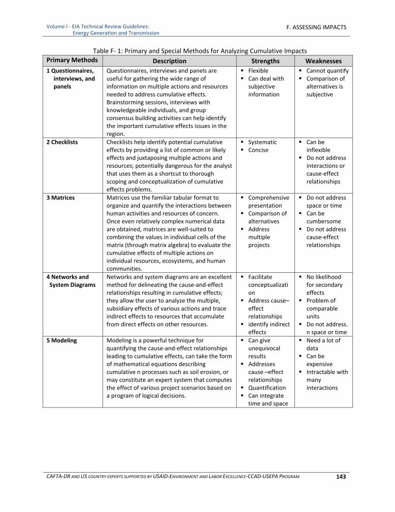
Volume I ‐ EIA Technical Review Guidelines: Energy Generation and Transmission
F. ASSESSING IMPACTS
CAFTA‐DR AND US COUNTRY EXPERTS SUPPORTED BY USAID‐ENVIRONMENT AND LABOR EXCELLENCE‐CCAD‐USEPA PROGRAM 143
Table F‐ 1: Primary and Special Methods for Analyzing Cumulative Impacts
Primary Methods Description Strengths Weaknesses
1 Questionnaires, interviews, and panels
Questionnaires, interviews and panels are useful for gathering the wide range of information on multiple actions and resources needed to address cumulative effects. Brainstorming sessions, interviews with knowledgeable individuals, and group consensus building activities can help identify the important cumulative effects issues in the region.
Flexible Can deal with
subjective information
Cannot quantify Comparison of
alternatives is subjective
2 Checklists Checklists help identify potential cumulative effects by providing a list of common or likely effects and juxtaposing multiple actions and resources; potentially dangerous for the analyst that uses them as a shortcut to thorough scoping and conceptualization of cumulative effects problems.
Systematic Concise
Can be inflexible
Do not address interactions or cause‐effect relationships
3 Matrices Matrices use the familiar tabular format to organize and quantify the interactions between human activities and resources of concern. Once even relatively complex numerical data are obtained, matrices are well‐suited to combining the values in individual cells of the matrix (through matrix algebra) to evaluate the cumulative effects of multiple actions on individual resources, ecosystems, and human communities.
Comprehensive presentation
Comparison of alternatives
Address multiple projects
Do not address space or time
Can be cumbersome
Do not address cause‐effect relationships
4 Networks and System Diagrams
Networks and system diagrams are an excellent method for delineating the cause‐and‐effect relationships resulting in cumulative effects; they allow the user to analyze the multiple, subsidiary effects of various actions and trace indirect effects to resources that accumulate from direct effects on other resources.
Facilitate conceptualization
Address cause–effect relationships
identify indirect effects
No likelihood for secondary effects
Problem of comparable units
Do not address. n space or time
5 Modeling Modeling is a powerful technique for quantifying the cause‐and‐effect relationships leading to cumulative effects, can take the form of mathematical equations describing cumulative n processes such as soil erosion, or may constitute an expert system that computes the effect of various project scenarios based on a program of logical decisions.
Can give unequivocal results
Addresses cause –effect relationships
Quantification Can integrate
time and space
Need a lot of data
Can be expensive
Intractable with many interactions
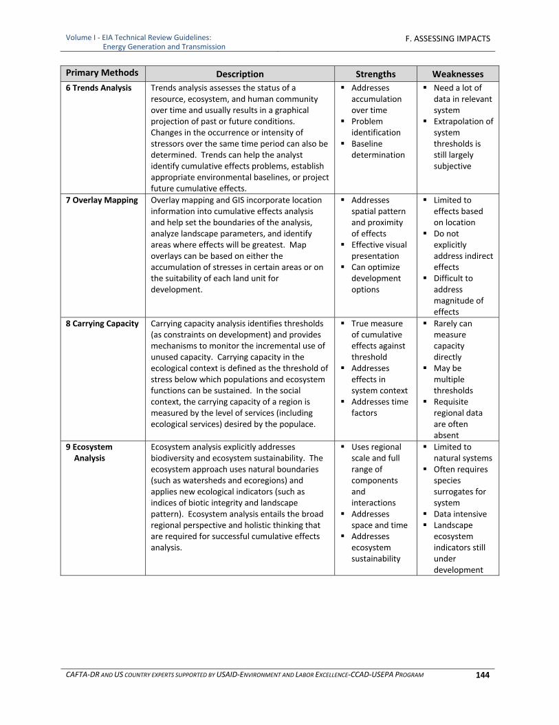
Volume I ‐ EIA Technical Review Guidelines: Energy Generation and Transmission
F. ASSESSING IMPACTS
CAFTA‐DR AND US COUNTRY EXPERTS SUPPORTED BY USAID‐ENVIRONMENT AND LABOR EXCELLENCE‐CCAD‐USEPA PROGRAM 144
Primary Methods Description Strengths Weaknesses
6 Trends Analysis Trends analysis assesses the status of a resource, ecosystem, and human community over time and usually results in a graphical projection of past or future conditions. Changes in the occurrence or intensity of stressors over the same time period can also be determined. Trends can help the analyst identify cumulative effects problems, establish appropriate environmental baselines, or project future cumulative effects.
Addresses accumulation over time
Problem identification
Baseline determination
Need a lot of data in relevant system
Extrapolation of system thresholds is still largely subjective
7 Overlay Mapping Overlay mapping and GIS incorporate location information into cumulative effects analysis and help set the boundaries of the analysis, analyze landscape parameters, and identify areas where effects will be greatest. Map overlays can be based on either the accumulation of stresses in certain areas or on the suitability of each land unit for development.
Addresses spatial pattern and proximity of effects
Effective visual presentation
Can optimize development options
Limited to effects based on location
Do not explicitly address indirect effects
Difficult to address magnitude of effects
8 Carrying Capacity Carrying capacity analysis identifies thresholds (as constraints on development) and provides mechanisms to monitor the incremental use of unused capacity. Carrying capacity in the ecological context is defined as the threshold of stress below which populations and ecosystem functions can be sustained. In the social context, the carrying capacity of a region is measured by the level of services (including ecological services) desired by the populace.
True measure of cumulative effects against threshold
Addresses effects in system context
Addresses time factors
Rarely can measure capacity directly
May be multiple thresholds
Requisite regional data are often absent
9 Ecosystem Analysis
Ecosystem analysis explicitly addresses biodiversity and ecosystem sustainability. The ecosystem approach uses natural boundaries (such as watersheds and ecoregions) and applies new ecological indicators (such as indices of biotic integrity and landscape pattern). Ecosystem analysis entails the broad regional perspective and holistic thinking that are required for successful cumulative effects analysis.
Uses regional scale and full range of components and interactions
Addresses space and time
Addresses ecosystem sustainability
Limited to natural systems
Often requires species surrogates for system
Data intensive Landscape
ecosystem indicators still under development
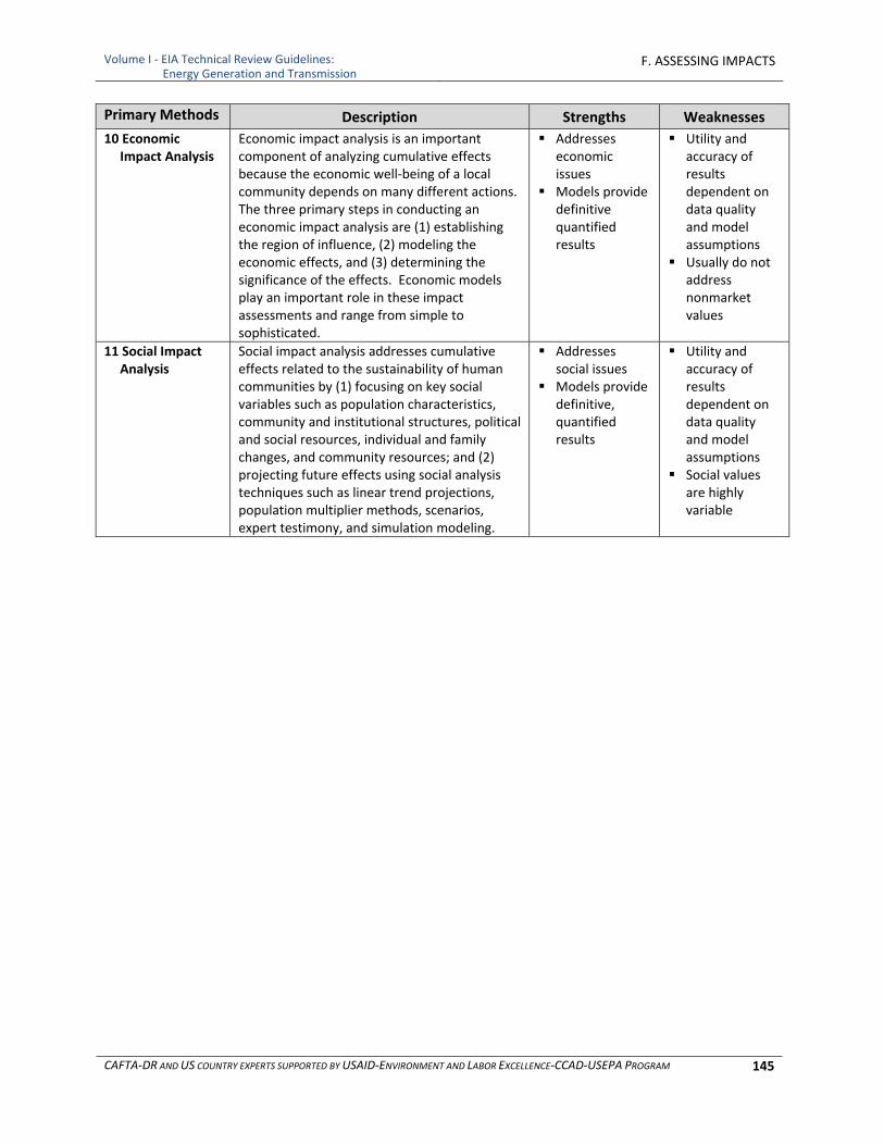
Volume I ‐ EIA Technical Review Guidelines: Energy Generation and Transmission
F. ASSESSING IMPACTS
CAFTA‐DR AND US COUNTRY EXPERTS SUPPORTED BY USAID‐ENVIRONMENT AND LABOR EXCELLENCE‐CCAD‐USEPA PROGRAM 145
Primary Methods Description Strengths Weaknesses
10 Economic Impact Analysis
Economic impact analysis is an important component of analyzing cumulative effects because the economic well‐being of a local community depends on many different actions. The three primary steps in conducting an economic impact analysis are (1) establishing the region of influence, (2) modeling the economic effects, and (3) determining the significance of the effects. Economic models play an important role in these impact assessments and range from simple to sophisticated.
Addresses economic issues
Models provide definitive quantified results
Utility and accuracy of results dependent on data quality and model assumptions
Usually do not address nonmarket values
11 Social Impact Analysis
Social impact analysis addresses cumulative effects related to the sustainability of human communities by (1) focusing on key social variables such as population characteristics, community and institutional structures, political and social resources, individual and family changes, and community resources; and (2) projecting future effects using social analysis techniques such as linear trend projections, population multiplier methods, scenarios, expert testimony, and simulation modeling.
Addresses social issues
Models provide definitive, quantified results
Utility and accuracy of results dependent on data quality and model assumptions
Social values are highly variable

Volume I ‐ EIA Technical Review Guidelines: Energy Generation and Transmission
F. ASSESSING IMPACTS
CAFTA‐DR AND US COUNTRY EXPERTS SUPPORTED BY USAID‐ENVIRONMENT AND LABOR EXCELLENCE‐CCAD‐USEPA PROGRAM 146
[This page Is intentionally blank.]
Volume I ‐ EIA Technical Review Guidelines: Energy Generation and Transmission
G. MITIGATION AND MONITORING MEASURES
CAFTA‐DR AND US COUNTRY EXPERTS SUPPORTED BY USAID‐ENVIRONMENT AND LABOR EXCELLENCE‐CCAD‐USEPA PROGRAM 147
G. MITIGATION AND MONITORING MEASURES
1 INTRODUCTION
Mitigation and monitoring measures, sometimes referred to as “environmental measures,” are actions that can be taken to avoid, minimize, prevent and/or compensate for the impacts caused by energy generation and transmission projects. They can, among other actions, involve applying pollution control or prevention technologies, the replacement or relocation of impacted resources and the relocation of displaced persons. However defined, one of the important outcomes of the EIA process is the commitment made to implement measures to avoid or otherwise mitigate adverse impacts and to ensure that they are carried out effectively is. The particular language used to define and commit to implementing environmental measures, to achieving reasonably anticipated effectiveness and with appropriate timing is critical to successful outcomes, as are accompanying requirements for monitoring, reporting and record keeping. They should be auditable, and something those governments inspectors can confirm are in compliance. Countries vary as to whether it is the EIA document itself that includes the commitments for which project proponents are accountable or whether they are included in accompanying documents related to the EIA process, or incorporated into legally binding permits or licenses. Regardless of the vehicle, if the commitments are unclear or the basis for ensuring their effectiveness difficult to establish, the beneficial outcomes of the EIA process will not be secured. To elaborate on some of the basic concepts behind mitigation or environmental measures:
Avoidance: Project proponents should be encouraged to avoid adverse impacts through good choice of location, site planning and engineering design and to focus mitigation measures on those adverse impacts that are otherwise unavoidable. Such environmental measures should be clearly explained early in the EIA process, and should include operational, monitoring and response plans should unexpected impacts occur.
Mitigation: The consideration of mitigation of the impacts is necessary for all phases of construction, operation and closure in which adverse impacts cannot be avoided. It is important that the EIA identify and define all mitigation measures for a specific project. A mitigation measure could be the selection of a project site or design option that avoids a sensitive resource, different pollution control measures or processes or even resizing or phasing in construction in a different manner that may reduce, minimize or prevent impacts. To the extent that this may not be feasible, mitigation may also include measures to compensate for damages, losses or reduced value of resources. Results of monitoring may trigger further mitigation action if these results indicate there are problems that were not anticipated in the EIA.
Justification: The EIA should identify, define, quantitatively assess and provide technical and financial bases for all environmental measures proposed, particularly if there is a concern about the site or proposed measures are less than best available practices.
Performance Standards: In the development of an EIA it is important that, wherever possible, quantitative performance standards are established. These standards should be clearly

Volume I ‐ EIA Technical Review Guidelines: Energy Generation and Transmission
G. MITIGATION AND MONITORING MEASURES
CAFTA‐DR AND US COUNTRY EXPERTS SUPPORTED BY USAID‐ENVIRONMENT AND LABOR EXCELLENCE‐CCAD‐USEPA PROGRAM 148
presented in the EIA. Environmental standards with which compliance is to be demonstrated should be based on local standards and in the absence of such standards, should be based on international norms. Examples of performance standards and requirements for countries and international organizations are presented in Appendix C to Volume 2 of these Guidelines.
Monitoring and Reporting should occur to assure compliance with expectations and requirements presented in the EIA and agreed to in the approval process. To support this requirement an environmental monitoring plan should be developed by the project proponent and approved by the government agency and other organizations having jurisdiction over project performance. The scope and extent of monitoring depends upon various aspects of the construction, operation and decommissioning of the project and resultant impacts. Monitoring plans include an outline of objectives, a plan to meet the stated objectives, criteria for evaluation, a response plan to be executed should monitoring results fail to meet the accepted criteria. Monitoring plans are addressed in detail in subsection G‐3, Monitoring and Oversight. It should be clear that results of compliance monitoring and reporting may trigger further action if results indicate there are problems that were not anticipated in the EIA. For example, monitoring may show that the environmental impacts are greater than the estimates in the EIA or that the mitigation measures were not as effective as anticipated.
Financial Assurance of ability to sustain environmental measures and to implement corrective measures in the event of impacts in excess of those allowed also may need to be demonstrated depending upon the requirements of the country or institution.
Contingency Plans: The identification and development of plans to address risks is an important part of the EIA process. Three types of contingency plans are identified including plans to respond to monitoring results which demonstrate that a standard or quantitative performance limit has been exceeded; response to natural disasters such as risks of flooding, mudslides, earthquakes and volcanic eruptions, fires, spills, hurricanes, tsunamis and the like; and response to other types of risks. Best Practices/Sustainable Development Standards: Best practices have been developed by various international and domestic organizations to both avoid and minimize adverse impacts. Governments may already require some of these practices but often they are voluntary. Increasingly social and economic pressure is favoring such established practices. In the context of EIA, some or all of these best practices might be integrated in project proposals and alternatives under consideration. The information on mitigation measures includes but is not limited to best practices.
Mitigation measures are presented in the following three tables.
Table G‐1 presents a comprehensive list of mitigation measures for impacts to the physical and biological environment that are appropriate for nearly all power generation and transmission projects is presented in. The table is organized by impacted environments.
Table G‐2 presents additional mitigation measures for impacts to the physical and biological environment that are applicable to specific power generation and transmission technologies.
Table G‐3 presents mitigation measures for impacts on the social‐economic‐cultural environment.

Volume I ‐ EIA Technical Review Guidelines: Energy Generation and Transmission
G. MITIGATION AND MONITORING MEASURES
CAFTA‐DR AND US COUNTRY EXPERTS SUPPORTED BY USAID‐ENVIRONMENT AND LABOR EXCELLENCE‐CCAD‐USEPA PROGRAM 149
It is unlikely that all of these measures will be applicable to a specific proposed facility. The proposed facility technology, location and design, in addition any regulatory agency requirement, will determine the appropriate measures for a particular project. The tables are followed by subsections that provide background information for several of the mitigation presented in the tables.
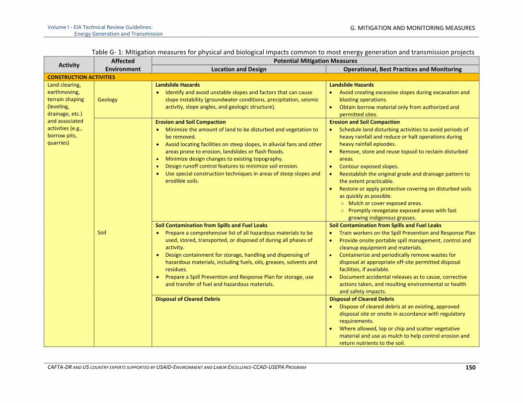
Volume I ‐ EIA Technical Review Guidelines: Energy Generation and Transmission
G. MITIGATION AND MONITORING MEASURES
CAFTA‐DR AND US COUNTRY EXPERTS SUPPORTED BY USAID‐ENVIRONMENT AND LABOR EXCELLENCE‐CCAD‐USEPA PROGRAM 150
Table G‐ 1: Mitigation measures for physical and biological impacts common to most energy generation and transmission projects
Activity Affected
Environment Potential Mitigation Measures
Location and Design Operational, Best Practices and MonitoringCONSTRUCTION ACTIVITIES
Land clearing, earthmoving, terrain shaping (leveling, drainage, etc.) and associated activities (e.g., borrow pits, quarries)
Geology
Landslide Hazards
Identify and avoid unstable slopes and factors that can cause slope instability (groundwater conditions, precipitation, seismic activity, slope angles, and geologic structure).
Landslide Hazards
Avoid creating excessive slopes during excavation and blasting operations.
Obtain borrow material only from authorized and permitted sites.
Soil
Erosion and Soil Compaction
Minimize the amount of land to be disturbed and vegetation to be removed.
Avoid locating facilities on steep slopes, in alluvial fans and other areas prone to erosion, landslides or flash floods.
Minimize design changes to existing topography. Design runoff control features to minimize soil erosion.
Use special construction techniques in areas of steep slopes and erodible soils.
Erosion and Soil Compaction
Schedule land disturbing activities to avoid periods of heavy rainfall and reduce or halt operations during heavy rainfall episodes.
Remove, store and reuse topsoil to reclaim disturbed areas.
Contour exposed slopes.
Reestablish the original grade and drainage pattern to the extent practicable.
Restore or apply protective covering on disturbed soils as quickly as possible. ○ Mulch or cover exposed areas. ○ Promptly revegetate exposed areas with fast
growing indigenous grasses.
Soil Contamination from Spills and Fuel Leaks
Prepare a comprehensive list of all hazardous materials to be used, stored, transported, or disposed of during all phases of activity.
Design containment for storage, handling and dispensing of hazardous materials, including fuels, oils, greases, solvents and residues.
Prepare a Spill Prevention and Response Plan for storage, use and transfer of fuel and hazardous materials.
Soil Contamination from Spills and Fuel Leaks
Train workers on the Spill Prevention and Response Plan
Provide onsite portable spill management, control and cleanup equipment and materials.
Containerize and periodically remove wastes for disposal at appropriate off‐site permitted disposal facilities, if available.
Document accidental releases as to cause, corrective actions taken, and resulting environmental or health and safety impacts.
Disposal of Cleared Debris Disposal of Cleared Debris
Dispose of cleared debris at an existing, approved disposal site or onsite in accordance with regulatory requirements.
Where allowed, lop or chip and scatter vegetative material and use as mulch to help control erosion and return nutrients to the soil.
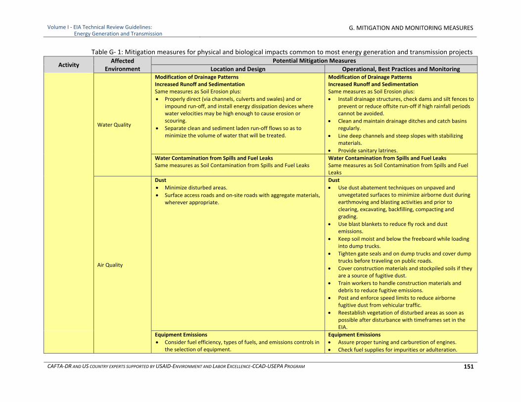
Volume I ‐ EIA Technical Review Guidelines: Energy Generation and Transmission
G. MITIGATION AND MONITORING MEASURES
CAFTA‐DR AND US COUNTRY EXPERTS SUPPORTED BY USAID‐ENVIRONMENT AND LABOR EXCELLENCE‐CCAD‐USEPA PROGRAM 151
Table G‐ 1: Mitigation measures for physical and biological impacts common to most energy generation and transmission projects
Activity Affected
Environment Potential Mitigation Measures
Location and Design Operational, Best Practices and Monitoring
Water Quality
Modification of Drainage Patterns Increased Runoff and Sedimentation Same measures as Soil Erosion plus:
Properly direct (via channels, culverts and swales) and or impound run‐off, and install energy dissipation devices where water velocities may be high enough to cause erosion or scouring.
Separate clean and sediment laden run‐off flows so as to minimize the volume of water that will be treated.
Modification of Drainage Patterns Increased Runoff and Sedimentation Same measures as Soil Erosion plus:
Install drainage structures, check dams and silt fences to prevent or reduce offsite run‐off if high rainfall periods cannot be avoided.
Clean and maintain drainage ditches and catch basins regularly.
Line deep channels and steep slopes with stabilizing materials.
Provide sanitary latrines.
Water Contamination from Spills and Fuel Leaks Same measures as Soil Contamination from Spills and Fuel Leaks
Water Contamination from Spills and Fuel Leaks Same measures as Soil Contamination from Spills and Fuel Leaks
Air Quality
Dust
Minimize disturbed areas.
Surface access roads and on‐site roads with aggregate materials, wherever appropriate.
Dust
Use dust abatement techniques on unpaved and unvegetated surfaces to minimize airborne dust during earthmoving and blasting activities and prior to clearing, excavating, backfilling, compacting and grading.
Use blast blankets to reduce fly rock and dust emissions.
Keep soil moist and below the freeboard while loading into dump trucks.
Tighten gate seals and on dump trucks and cover dump trucks before traveling on public roads.
Cover construction materials and stockpiled soils if they are a source of fugitive dust.
Train workers to handle construction materials and debris to reduce fugitive emissions.
Post and enforce speed limits to reduce airborne fugitive dust from vehicular traffic.
Reestablish vegetation of disturbed areas as soon as possible after disturbance with timeframes set in the EIA.
Equipment Emissions
Consider fuel efficiency, types of fuels, and emissions controls in the selection of equipment.
Equipment Emissions
Assure proper tuning and carburetion of engines.
Check fuel supplies for impurities or adulteration.
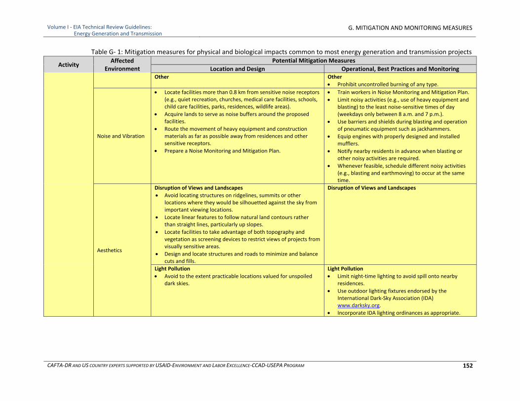
Volume I ‐ EIA Technical Review Guidelines: Energy Generation and Transmission
G. MITIGATION AND MONITORING MEASURES
CAFTA‐DR AND US COUNTRY EXPERTS SUPPORTED BY USAID‐ENVIRONMENT AND LABOR EXCELLENCE‐CCAD‐USEPA PROGRAM 152
Table G‐ 1: Mitigation measures for physical and biological impacts common to most energy generation and transmission projects
Activity Affected
Environment Potential Mitigation Measures
Location and Design Operational, Best Practices and MonitoringOther Other
Prohibit uncontrolled burning of any type.
Noise and Vibration
Locate facilities more than 0.8 km from sensitive noise receptors (e.g., quiet recreation, churches, medical care facilities, schools, child care facilities, parks, residences, wildlife areas).
Acquire lands to serve as noise buffers around the proposed facilities.
Route the movement of heavy equipment and construction materials as far as possible away from residences and other sensitive receptors.
Prepare a Noise Monitoring and Mitigation Plan.
Train workers in Noise Monitoring and Mitigation Plan.
Limit noisy activities (e.g., use of heavy equipment and blasting) to the least noise‐sensitive times of day (weekdays only between 8 a.m. and 7 p.m.).
Use barriers and shields during blasting and operation of pneumatic equipment such as jackhammers.
Equip engines with properly designed and installed mufflers.
Notify nearby residents in advance when blasting or other noisy activities are required.
Whenever feasible, schedule different noisy activities (e.g., blasting and earthmoving) to occur at the same time.
Aesthetics
Disruption of Views and Landscapes
Avoid locating structures on ridgelines, summits or other locations where they would be silhouetted against the sky from important viewing locations.
Locate linear features to follow natural land contours rather than straight lines, particularly up slopes.
Locate facilities to take advantage of both topography and vegetation as screening devices to restrict views of projects from visually sensitive areas.
Design and locate structures and roads to minimize and balance cuts and fills.
Disruption of Views and Landscapes
Light Pollution
Avoid to the extent practicable locations valued for unspoiled dark skies.
Light Pollution
Limit night‐time lighting to avoid spill onto nearby residences.
Use outdoor lighting fixtures endorsed by the International Dark‐Sky Association (IDA) www.darksky.org.
Incorporate IDA lighting ordinances as appropriate.
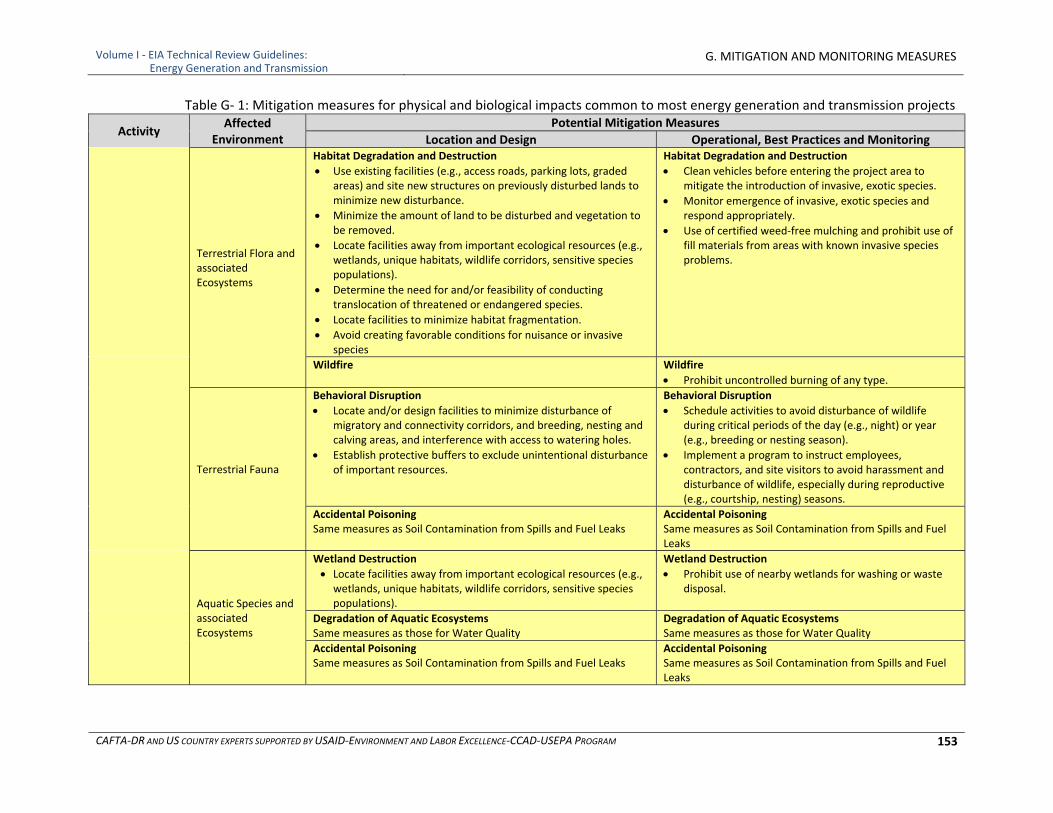
Volume I ‐ EIA Technical Review Guidelines: Energy Generation and Transmission
G. MITIGATION AND MONITORING MEASURES
CAFTA‐DR AND US COUNTRY EXPERTS SUPPORTED BY USAID‐ENVIRONMENT AND LABOR EXCELLENCE‐CCAD‐USEPA PROGRAM 153
Table G‐ 1: Mitigation measures for physical and biological impacts common to most energy generation and transmission projects
Activity Affected
Environment Potential Mitigation Measures
Location and Design Operational, Best Practices and Monitoring
Terrestrial Flora and associated Ecosystems
Habitat Degradation and Destruction
Use existing facilities (e.g., access roads, parking lots, graded areas) and site new structures on previously disturbed lands to minimize new disturbance.
Minimize the amount of land to be disturbed and vegetation to be removed.
Locate facilities away from important ecological resources (e.g., wetlands, unique habitats, wildlife corridors, sensitive species populations).
Determine the need for and/or feasibility of conducting translocation of threatened or endangered species.
Locate facilities to minimize habitat fragmentation.
Avoid creating favorable conditions for nuisance or invasive species
Habitat Degradation and Destruction
Clean vehicles before entering the project area to mitigate the introduction of invasive, exotic species.
Monitor emergence of invasive, exotic species and respond appropriately.
Use of certified weed‐free mulching and prohibit use of fill materials from areas with known invasive species problems.
Wildfire Wildfire
Prohibit uncontrolled burning of any type.
Terrestrial Fauna
Behavioral Disruption
Locate and/or design facilities to minimize disturbance of migratory and connectivity corridors, and breeding, nesting and calving areas, and interference with access to watering holes.
Establish protective buffers to exclude unintentional disturbance of important resources.
Behavioral Disruption
Schedule activities to avoid disturbance of wildlife during critical periods of the day (e.g., night) or year (e.g., breeding or nesting season).
Implement a program to instruct employees, contractors, and site visitors to avoid harassment and disturbance of wildlife, especially during reproductive (e.g., courtship, nesting) seasons.
Accidental Poisoning Same measures as Soil Contamination from Spills and Fuel Leaks
Accidental Poisoning Same measures as Soil Contamination from Spills and Fuel Leaks
Aquatic Species and associated Ecosystems
Wetland Destruction
Locate facilities away from important ecological resources (e.g., wetlands, unique habitats, wildlife corridors, sensitive species populations).
Wetland Destruction
Prohibit use of nearby wetlands for washing or waste disposal.
Degradation of Aquatic Ecosystems Same measures as those for Water Quality
Degradation of Aquatic Ecosystems Same measures as those for Water Quality
Accidental Poisoning Same measures as Soil Contamination from Spills and Fuel Leaks
Accidental Poisoning Same measures as Soil Contamination from Spills and Fuel Leaks
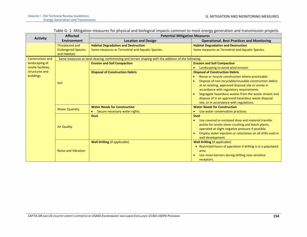
Volume I ‐ EIA Technical Review Guidelines: Energy Generation and Transmission
G. MITIGATION AND MONITORING MEASURES
CAFTA‐DR AND US COUNTRY EXPERTS SUPPORTED BY USAID‐ENVIRONMENT AND LABOR EXCELLENCE‐CCAD‐USEPA PROGRAM 154
Table G‐ 1: Mitigation measures for physical and biological impacts common to most energy generation and transmission projects
Activity Affected
Environment Potential Mitigation Measures
Location and Design Operational, Best Practices and MonitoringThreatened and Endangered Species and Habitats
Habitat Degradation and Destruction Same measures as Terrestrial and Aquatic Species.
Habitat Degradation and Destruction Same measures as Terrestrial and Aquatic Species.
Construction and landscaping of onsite facilities, structures and buildings
Same measures as land clearing, earthmoving and terrain shaping with the addition of the following:
Soil
Erosion and Soil Compaction Erosion and Soil Compaction
Landscaping to avoid wind erosion.
Disposal of Construction Debris Disposal of Construction Debris
Reuse or recycle construction where practicable.
Dispose of non‐recyclable/reusable construction debris at an existing, approved disposal site or onsite in accordance with regulatory requirements.
Segregate hazardous wastes from the waste stream and dispose of in an approved hazardous waste disposal site, or in accordance with regulations.
Water Quantity Water Needs for Construction
Secure necessary water rights.
Water Needs for Construction
Use water conservation practices.
Air Quality
Dust Dust
Use covered or enclosed drop and material transfer points for onsite stone crushing and batch plants, operated at slight negative pressure if possible.
Employ water injection or rotoclones on all drills used in well development.
Noise and Vibration
Well Drilling (if applicable) Well Drilling (if applicable)
Restricted hours of operation if drilling is in a populated area.
Use noise barriers during drilling near sensitive receptors.
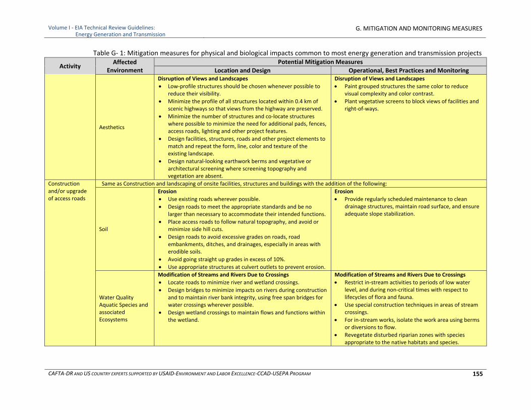
Volume I ‐ EIA Technical Review Guidelines: Energy Generation and Transmission
G. MITIGATION AND MONITORING MEASURES
CAFTA‐DR AND US COUNTRY EXPERTS SUPPORTED BY USAID‐ENVIRONMENT AND LABOR EXCELLENCE‐CCAD‐USEPA PROGRAM 155
Table G‐ 1: Mitigation measures for physical and biological impacts common to most energy generation and transmission projects
Activity Affected
Environment Potential Mitigation Measures
Location and Design Operational, Best Practices and Monitoring
Aesthetics
Disruption of Views and Landscapes
Low‐profile structures should be chosen whenever possible to reduce their visibility.
Minimize the profile of all structures located within 0.4 km of scenic highways so that views from the highway are preserved.
Minimize the number of structures and co‐locate structures where possible to minimize the need for additional pads, fences, access roads, lighting and other project features.
Design facilities, structures, roads and other project elements to match and repeat the form, line, color and texture of the existing landscape.
Design natural‐looking earthwork berms and vegetative or architectural screening where screening topography and vegetation are absent.
Disruption of Views and Landscapes
Paint grouped structures the same color to reduce visual complexity and color contrast.
Plant vegetative screens to block views of facilities and right‐of‐ways.
Construction and/or upgrade of access roads
Same as Construction and landscaping of onsite facilities, structures and buildings with the addition of the following:
Soil
Erosion
Use existing roads wherever possible.
Design roads to meet the appropriate standards and be no larger than necessary to accommodate their intended functions.
Place access roads to follow natural topography, and avoid or minimize side hill cuts.
Design roads to avoid excessive grades on roads, road embankments, ditches, and drainages, especially in areas with erodible soils.
Avoid going straight up grades in excess of 10%.
Use appropriate structures at culvert outlets to prevent erosion.
Erosion
Provide regularly scheduled maintenance to clean drainage structures, maintain road surface, and ensure adequate slope stabilization.
Water Quality Aquatic Species and associated Ecosystems
Modification of Streams and Rivers Due to Crossings
Locate roads to minimize river and wetland crossings.
Design bridges to minimize impacts on rivers during construction and to maintain river bank integrity, using free span bridges for water crossings wherever possible.
Design wetland crossings to maintain flows and functions within the wetland.
Modification of Streams and Rivers Due to Crossings
Restrict in‐stream activities to periods of low water level, and during non‐critical times with respect to lifecycles of flora and fauna.
Use special construction techniques in areas of stream crossings.
For in‐stream works, isolate the work area using berms or diversions to flow.
Revegetate disturbed riparian zones with species appropriate to the native habitats and species.
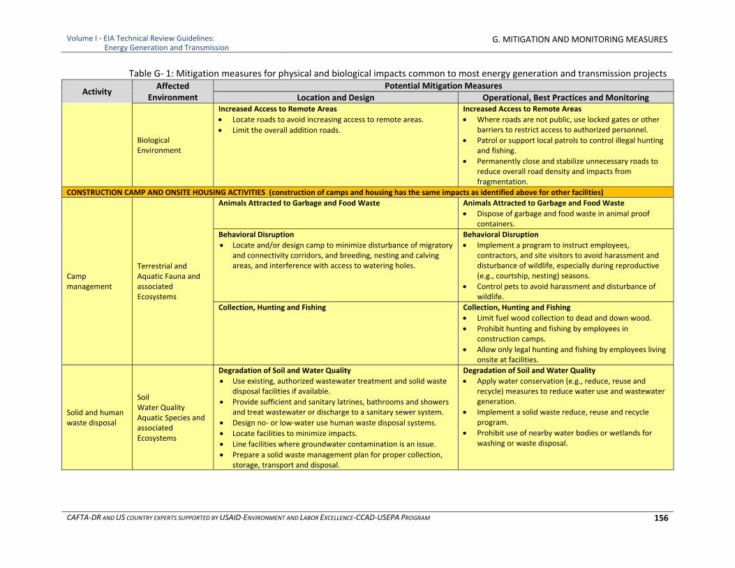
Volume I ‐ EIA Technical Review Guidelines: Energy Generation and Transmission
G. MITIGATION AND MONITORING MEASURES
CAFTA‐DR AND US COUNTRY EXPERTS SUPPORTED BY USAID‐ENVIRONMENT AND LABOR EXCELLENCE‐CCAD‐USEPA PROGRAM 156
Table G‐ 1: Mitigation measures for physical and biological impacts common to most energy generation and transmission projects
Activity Affected
Environment Potential Mitigation Measures
Location and Design Operational, Best Practices and Monitoring
Biological Environment
Increased Access to Remote Areas
Locate roads to avoid increasing access to remote areas.
Limit the overall addition roads.
Increased Access to Remote Areas
Where roads are not public, use locked gates or other barriers to restrict access to authorized personnel.
Patrol or support local patrols to control illegal hunting and fishing.
Permanently close and stabilize unnecessary roads to reduce overall road density and impacts from fragmentation.
CONSTRUCTION CAMP AND ONSITE HOUSING ACTIVITIES (construction of camps and housing has the same impacts as identified above for other facilities)
Camp management
Terrestrial and Aquatic Fauna and associated Ecosystems
Animals Attracted to Garbage and Food Waste Animals Attracted to Garbage and Food Waste
Dispose of garbage and food waste in animal proof containers.
Behavioral Disruption
Locate and/or design camp to minimize disturbance of migratory and connectivity corridors, and breeding, nesting and calving areas, and interference with access to watering holes.
Behavioral Disruption
Implement a program to instruct employees, contractors, and site visitors to avoid harassment and disturbance of wildlife, especially during reproductive (e.g., courtship, nesting) seasons.
Control pets to avoid harassment and disturbance of wildlife.
Collection, Hunting and Fishing Collection, Hunting and Fishing
Limit fuel wood collection to dead and down wood.
Prohibit hunting and fishing by employees in construction camps.
Allow only legal hunting and fishing by employees living onsite at facilities.
Solid and human waste disposal
Soil Water Quality Aquatic Species and associated Ecosystems
Degradation of Soil and Water Quality
Use existing, authorized wastewater treatment and solid waste disposal facilities if available.
Provide sufficient and sanitary latrines, bathrooms and showers and treat wastewater or discharge to a sanitary sewer system.
Design no‐ or low‐water use human waste disposal systems.
Locate facilities to minimize impacts.
Line facilities where groundwater contamination is an issue.
Prepare a solid waste management plan for proper collection, storage, transport and disposal.
Degradation of Soil and Water Quality
Apply water conservation (e.g., reduce, reuse and recycle) measures to reduce water use and wastewater generation.
Implement a solid waste reduce, reuse and recycle program.
Prohibit use of nearby water bodies or wetlands for washing or waste disposal.
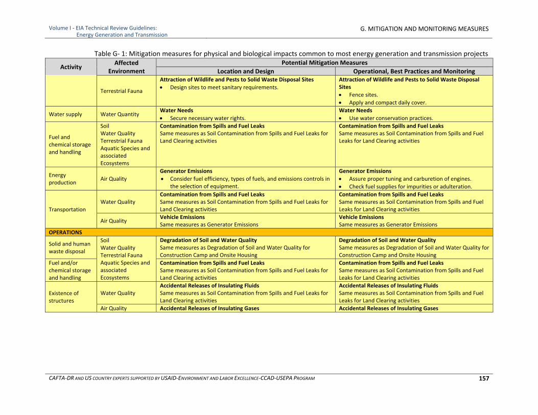
Volume I ‐ EIA Technical Review Guidelines: Energy Generation and Transmission
G. MITIGATION AND MONITORING MEASURES
CAFTA‐DR AND US COUNTRY EXPERTS SUPPORTED BY USAID‐ENVIRONMENT AND LABOR EXCELLENCE‐CCAD‐USEPA PROGRAM 157
Table G‐ 1: Mitigation measures for physical and biological impacts common to most energy generation and transmission projects
Activity Affected
Environment Potential Mitigation Measures
Location and Design Operational, Best Practices and Monitoring
Terrestrial Fauna
Attraction of Wildlife and Pests to Solid Waste Disposal Sites
Design sites to meet sanitary requirements.
Attraction of Wildlife and Pests to Solid Waste Disposal Sites
Fence sites.
Apply and compact daily cover.
Water supply Water Quantity Water Needs
Secure necessary water rights.
Water Needs
Use water conservation practices.
Fuel and chemical storage and handling
Soil Water Quality Terrestrial Fauna Aquatic Species and associated Ecosystems
Contamination from Spills and Fuel Leaks Same measures as Soil Contamination from Spills and Fuel Leaks for Land Clearing activities
Contamination from Spills and Fuel Leaks Same measures as Soil Contamination from Spills and Fuel Leaks for Land Clearing activities
Energy production
Air Quality
Generator Emissions
Consider fuel efficiency, types of fuels, and emissions controls in the selection of equipment.
Generator Emissions
Assure proper tuning and carburetion of engines.
Check fuel supplies for impurities or adulteration.
Transportation Water Quality
Contamination from Spills and Fuel Leaks Same measures as Soil Contamination from Spills and Fuel Leaks for Land Clearing activities
Contamination from Spills and Fuel Leaks Same measures as Soil Contamination from Spills and Fuel Leaks for Land Clearing activities
Air Quality Vehicle Emissions Same measures as Generator Emissions
Vehicle Emissions Same measures as Generator Emissions
OPERATIONS
Solid and human waste disposal
Soil Water Quality Terrestrial Fauna Aquatic Species and associated Ecosystems
Degradation of Soil and Water Quality Same measures as Degradation of Soil and Water Quality for Construction Camp and Onsite Housing
Degradation of Soil and Water Quality Same measures as Degradation of Soil and Water Quality for Construction Camp and Onsite Housing
Fuel and/or chemical storage and handling
Contamination from Spills and Fuel Leaks Same measures as Soil Contamination from Spills and Fuel Leaks for Land Clearing activities
Contamination from Spills and Fuel Leaks Same measures as Soil Contamination from Spills and Fuel Leaks for Land Clearing activities
Existence of structures
Water Quality Accidental Releases of Insulating Fluids Same measures as Soil Contamination from Spills and Fuel Leaks for Land Clearing activities
Accidental Releases of Insulating Fluids Same measures as Soil Contamination from Spills and Fuel Leaks for Land Clearing activities
Air Quality Accidental Releases of Insulating Gases Accidental Releases of Insulating Gases
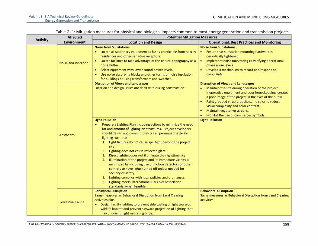
Volume I ‐ EIA Technical Review Guidelines: Energy Generation and Transmission
G. MITIGATION AND MONITORING MEASURES
CAFTA‐DR AND US COUNTRY EXPERTS SUPPORTED BY USAID‐ENVIRONMENT AND LABOR EXCELLENCE‐CCAD‐USEPA PROGRAM 158
Table G‐ 1: Mitigation measures for physical and biological impacts common to most energy generation and transmission projects
Activity Affected
Environment Potential Mitigation Measures
Location and Design Operational, Best Practices and Monitoring
Noise and Vibration
Noise from Substations
Locate all stationary equipment as far as practicable from nearby residences and other sensitive receptors.
Locate facilities to take advantage of the natural topography as a noise buffer.
Select equipment with lower sound power levels.
Use noise absorbing blocks and other forms of noise insulation for buildings housing transformers and switches.
Noise from Substations
Ensure that substation mounting hardware is periodically tightened.
Implement noise monitoring to verifying operational phase noise levels.
Develop a mechanism to record and respond to complaints.
Aesthetics
Disruption of Views and Landscapes Location and design issues are dealt with during construction.
Disruption of Views and Landscapes
Maintain the site during operation of the project. Inoperative equipment and poor housekeeping, creates a poor image of the project in the eyes of the public.
Paint grouped structures the same color to reduce visual complexity and color contrast.
Maintain vegetative screens.
Prohibit the use of commercial symbols.
Light Pollution
Prepare a Lighting Plan including actions to minimize the need for and amount of lighting on structures. Project developers should design and commit to install all permanent exterior lighting such that: 1. Light fixtures do not cause spill light beyond the project
site 2. Lighting does not cause reflected glare 3. Direct lighting does not illuminate the nighttime sky 4. Illumination of the project and its immediate vicinity is
minimized by including use of motion detectors or other controls to have lights turned off unless needed for security or safety
5. Lighting complies with local policies and ordinances 6. Lighting meets International Dark Sky Association
standards, when feasible.
Light Pollution
Terrestrial Fauna
Behavioral Disruption Same measures as Behavioral Disruption from Land Clearing activities plus:
Design facility lighting to prevent side casting of light towards wildlife habitat and prevent skyward projection of lighting that may disorient night migrating birds.
Behavioral Disruption Same measures as Behavioral Disruption from Land Clearing activities.
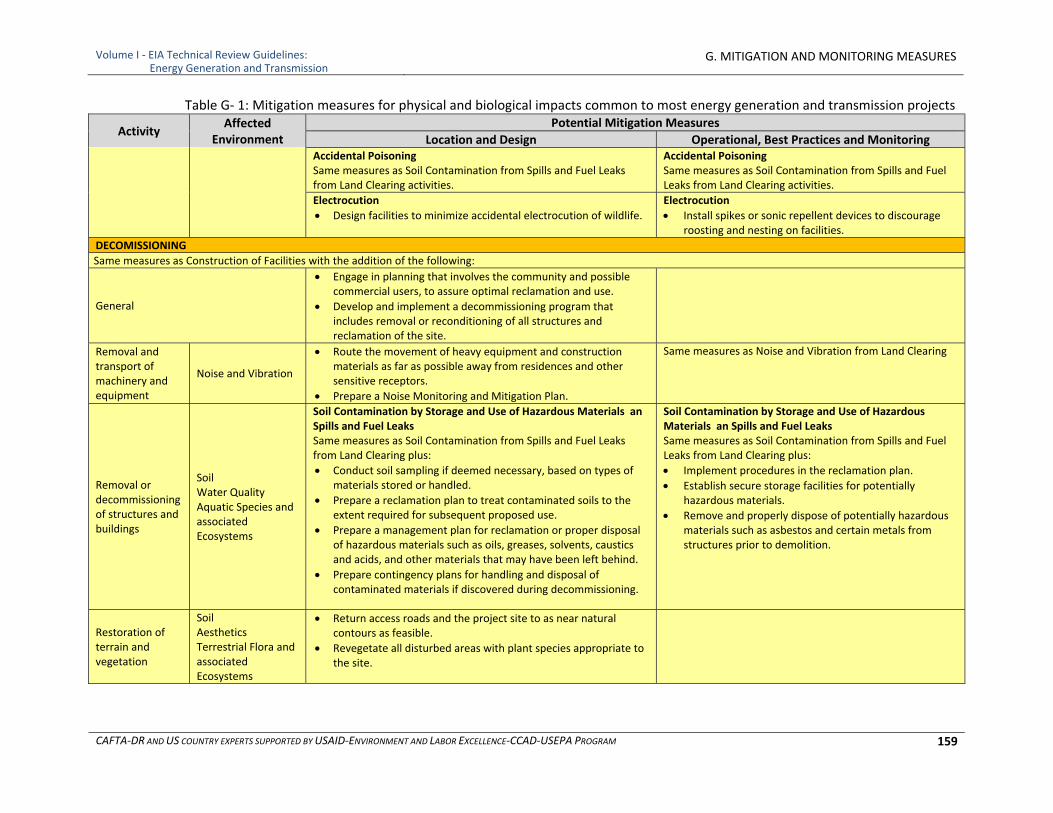
Volume I ‐ EIA Technical Review Guidelines: Energy Generation and Transmission
G. MITIGATION AND MONITORING MEASURES
CAFTA‐DR AND US COUNTRY EXPERTS SUPPORTED BY USAID‐ENVIRONMENT AND LABOR EXCELLENCE‐CCAD‐USEPA PROGRAM 159
Table G‐ 1: Mitigation measures for physical and biological impacts common to most energy generation and transmission projects
Activity Affected
Environment Potential Mitigation Measures
Location and Design Operational, Best Practices and MonitoringAccidental Poisoning Same measures as Soil Contamination from Spills and Fuel Leaks from Land Clearing activities.
Accidental Poisoning Same measures as Soil Contamination from Spills and Fuel Leaks from Land Clearing activities.
Electrocution
Design facilities to minimize accidental electrocution of wildlife.
Electrocution
Install spikes or sonic repellent devices to discourage roosting and nesting on facilities.
DECOMISSIONING
Same measures as Construction of Facilities with the addition of the following:
General
Engage in planning that involves the community and possible commercial users, to assure optimal reclamation and use.
Develop and implement a decommissioning program that includes removal or reconditioning of all structures and reclamation of the site.
Removal and transport of machinery and equipment
Noise and Vibration
Route the movement of heavy equipment and construction materials as far as possible away from residences and other sensitive receptors.
Prepare a Noise Monitoring and Mitigation Plan.
Same measures as Noise and Vibration from Land Clearing
Removal or decommissioning of structures and buildings
Soil Water Quality Aquatic Species and associated Ecosystems
Soil Contamination by Storage and Use of Hazardous Materials an Spills and Fuel Leaks Same measures as Soil Contamination from Spills and Fuel Leaks from Land Clearing plus:
Conduct soil sampling if deemed necessary, based on types of materials stored or handled.
Prepare a reclamation plan to treat contaminated soils to the extent required for subsequent proposed use.
Prepare a management plan for reclamation or proper disposal of hazardous materials such as oils, greases, solvents, caustics and acids, and other materials that may have been left behind.
Prepare contingency plans for handling and disposal of contaminated materials if discovered during decommissioning.
Soil Contamination by Storage and Use of Hazardous Materials an Spills and Fuel Leaks Same measures as Soil Contamination from Spills and Fuel Leaks from Land Clearing plus:
Implement procedures in the reclamation plan.
Establish secure storage facilities for potentially hazardous materials.
Remove and properly dispose of potentially hazardous materials such as asbestos and certain metals from structures prior to demolition.
Restoration of terrain and vegetation
Soil Aesthetics Terrestrial Flora and associated Ecosystems
Return access roads and the project site to as near natural contours as feasible.
Revegetate all disturbed areas with plant species appropriate to the site.
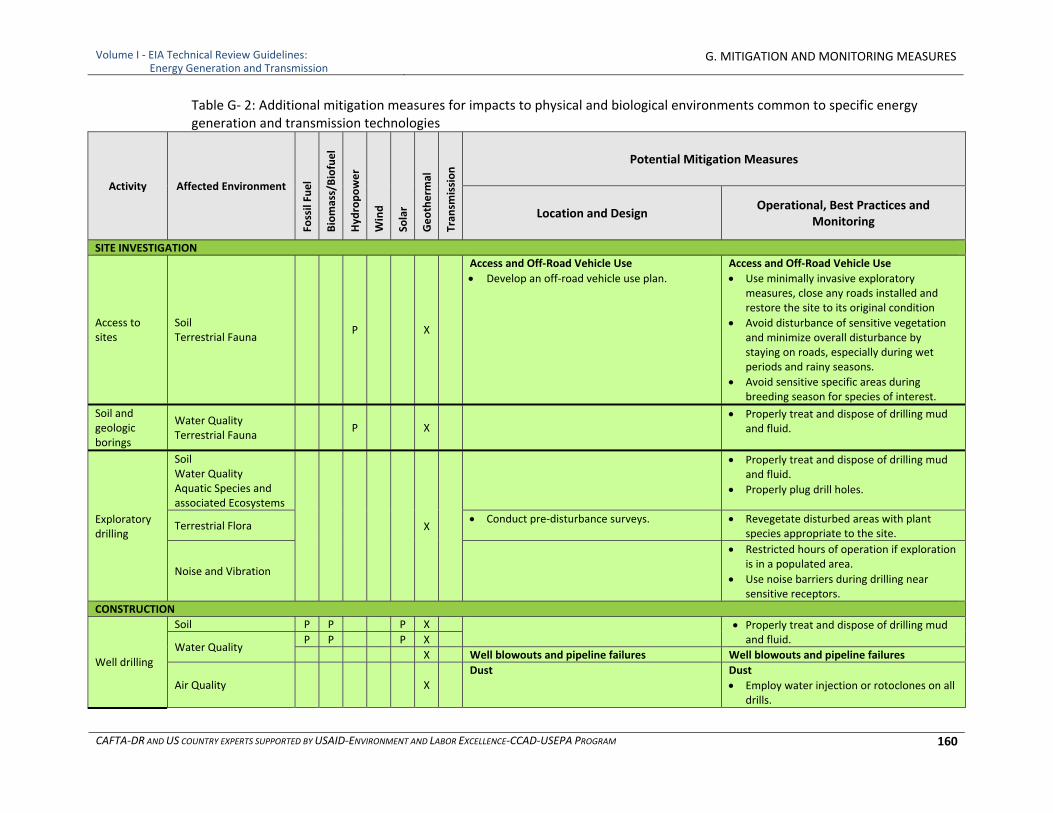
Volume I ‐ EIA Technical Review Guidelines: Energy Generation and Transmission
G. MITIGATION AND MONITORING MEASURES
CAFTA‐DR AND US COUNTRY EXPERTS SUPPORTED BY USAID‐ENVIRONMENT AND LABOR EXCELLENCE‐CCAD‐USEPA PROGRAM 160
Table G‐ 2: Additional mitigation measures for impacts to physical and biological environments common to specific energy generation and transmission technologies
Activity Affected Environment
Fossil Fuel
Biomass/Biofuel
Hyd
ropower
Wind
Solar
Geotherm
al
Tran
smission Potential Mitigation Measures
Location and Design Operational, Best Practices and
Monitoring
SITE INVESTIGATION
Access to sites
Soil Terrestrial Fauna
P X
Access and Off‐Road Vehicle Use
Develop an off‐road vehicle use plan.
Access and Off‐Road Vehicle Use
Use minimally invasive exploratory measures, close any roads installed and restore the site to its original condition
Avoid disturbance of sensitive vegetation and minimize overall disturbance by staying on roads, especially during wet periods and rainy seasons.
Avoid sensitive specific areas during breeding season for species of interest.
Soil and geologic borings
Water Quality Terrestrial Fauna
P X Properly treat and dispose of drilling mud
and fluid.
Exploratory drilling
Soil Water Quality Aquatic Species and associated Ecosystems
X
Properly treat and dispose of drilling mud and fluid.
Properly plug drill holes.
Terrestrial Flora Conduct pre‐disturbance surveys. Revegetate disturbed areas with plant
species appropriate to the site.
Noise and Vibration
Restricted hours of operation if exploration is in a populated area.
Use noise barriers during drilling near sensitive receptors.
CONSTRUCTION
Well drilling
Soil P P P X Properly treat and dispose of drilling mud and fluid.
Water Quality P P P X
X Well blowouts and pipeline failures Well blowouts and pipeline failures
Air Quality X Dust Dust
Employ water injection or rotoclones on all drills.
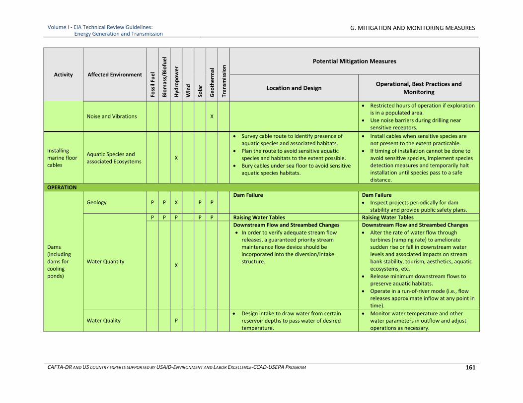
Volume I ‐ EIA Technical Review Guidelines: Energy Generation and Transmission
G. MITIGATION AND MONITORING MEASURES
CAFTA‐DR AND US COUNTRY EXPERTS SUPPORTED BY USAID‐ENVIRONMENT AND LABOR EXCELLENCE‐CCAD‐USEPA PROGRAM 161
Activity Affected Environment
Fossil Fuel
Biomass/Biofuel
Hyd
ropower
Wind
Solar
Geotherm
al
Tran
smission Potential Mitigation Measures
Location and Design Operational, Best Practices and
Monitoring
Noise and Vibrations X
Restricted hours of operation if exploration is in a populated area.
Use noise barriers during drilling near sensitive receptors.
Installing marine floor cables
Aquatic Species and associated Ecosystems
X
Survey cable route to identify presence of aquatic species and associated habitats.
Plan the route to avoid sensitive aquatic species and habitats to the extent possible.
Bury cables under sea floor to avoid sensitive aquatic species habitats.
Install cables when sensitive species are not present to the extent practicable.
If timing of installation cannot be done to avoid sensitive species, implement species detection measures and temporarily halt installation until species pass to a safe distance.
OPERATION
Dams (including dams for cooling ponds)
Geology P P X P P Dam Failure Dam Failure
Inspect projects periodically for dam stability and provide public safety plans.
Water Quantity
P P P P P Raising Water Tables Raising Water Tables
X
Downstream Flow and Streambed Changes
In order to verify adequate stream flow releases, a guaranteed priority stream maintenance flow device should be incorporated into the diversion/intake structure.
Downstream Flow and Streambed Changes
Alter the rate of water flow through turbines (ramping rate) to ameliorate sudden rise or fall in downstream water levels and associated impacts on stream bank stability, tourism, aesthetics, aquatic ecosystems, etc.
Release minimum downstream flows to preserve aquatic habitats.
Operate in a run‐of‐river mode (i.e., flow releases approximate inflow at any point in time).
Water Quality P Design intake to draw water from certain
reservoir depths to pass water of desired temperature.
Monitor water temperature and other water parameters in outflow and adjust operations as necessary.
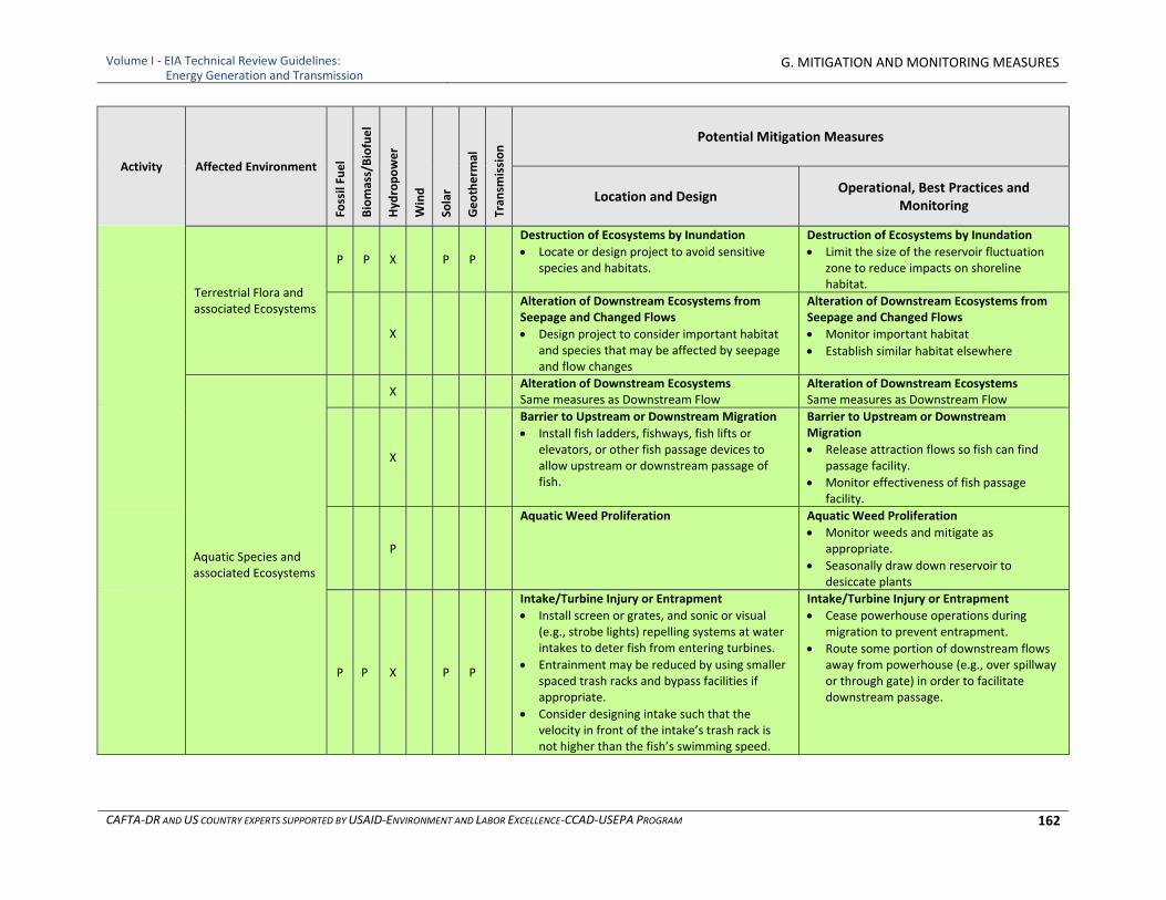
Volume I ‐ EIA Technical Review Guidelines: Energy Generation and Transmission
G. MITIGATION AND MONITORING MEASURES
CAFTA‐DR AND US COUNTRY EXPERTS SUPPORTED BY USAID‐ENVIRONMENT AND LABOR EXCELLENCE‐CCAD‐USEPA PROGRAM 162
Activity Affected Environment
Fossil Fuel
Biomass/Biofuel
Hyd
ropower
Wind
Solar
Geotherm
al
Tran
smission Potential Mitigation Measures
Location and Design Operational, Best Practices and
Monitoring
Terrestrial Flora and associated Ecosystems
P P X P P
Destruction of Ecosystems by Inundation
Locate or design project to avoid sensitive species and habitats.
Destruction of Ecosystems by Inundation
Limit the size of the reservoir fluctuation zone to reduce impacts on shoreline habitat.
X
Alteration of Downstream Ecosystems from Seepage and Changed Flows
Design project to consider important habitat and species that may be affected by seepage and flow changes
Alteration of Downstream Ecosystems from Seepage and Changed Flows
Monitor important habitat
Establish similar habitat elsewhere
Aquatic Species and associated Ecosystems
X Alteration of Downstream Ecosystems Same measures as Downstream Flow
Alteration of Downstream Ecosystems Same measures as Downstream Flow
X
Barrier to Upstream or Downstream Migration
Install fish ladders, fishways, fish lifts or elevators, or other fish passage devices to allow upstream or downstream passage of fish.
Barrier to Upstream or Downstream Migration
Release attraction flows so fish can find passage facility.
Monitor effectiveness of fish passage facility.
P
Aquatic Weed Proliferation Aquatic Weed Proliferation
Monitor weeds and mitigate as appropriate.
Seasonally draw down reservoir to desiccate plants
P P X P P
Intake/Turbine Injury or Entrapment
Install screen or grates, and sonic or visual (e.g., strobe lights) repelling systems at water intakes to deter fish from entering turbines.
Entrainment may be reduced by using smaller spaced trash racks and bypass facilities if appropriate.
Consider designing intake such that the velocity in front of the intake’s trash rack is not higher than the fish’s swimming speed.
Intake/Turbine Injury or Entrapment
Cease powerhouse operations during migration to prevent entrapment.
Route some portion of downstream flows away from powerhouse (e.g., over spillway or through gate) in order to facilitate downstream passage.
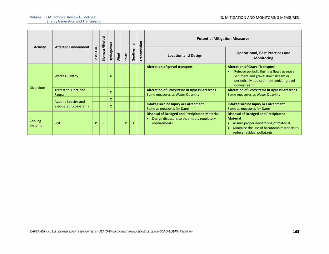
Volume I ‐ EIA Technical Review Guidelines: Energy Generation and Transmission
G. MITIGATION AND MONITORING MEASURES
CAFTA‐DR AND US COUNTRY EXPERTS SUPPORTED BY USAID‐ENVIRONMENT AND LABOR EXCELLENCE‐CCAD‐USEPA PROGRAM 163
Activity Affected Environment
Fossil Fuel
Biomass/Biofuel
Hyd
ropower
Wind
Solar
Geotherm
al
Tran
smission Potential Mitigation Measures
Location and Design Operational, Best Practices and
Monitoring
Diversions
Water Quantity X
Alteration of gravel transport Alteration of Gravel Transport
Release periodic flushing flows to move sediment and gravel downstream or periodically add sediment and/or gravel downstream.
Terrestrial Flora and Fauna
X Alteration of Ecosystems in Bypass Stretches Same measures as Water Quantity
Alteration of Ecosystems in Bypass Stretches Same measures as Water Quantity
Aquatic Species and associated Ecosystems
X
X Intake/Turbine Injury or Entrapment Same as measures for Dams
Intake/Turbine Injury or Entrapment Same as measures for Dams
Cooling systems
Soil P P P X
Disposal of Dredged and Precipitated Material
Design disposal site that meets regulatory requirements.
Disposal of Dredged and Precipitated Material
Assure proper dewatering of material.
Minimize the use of hazardous materials to reduce residual pollutants.
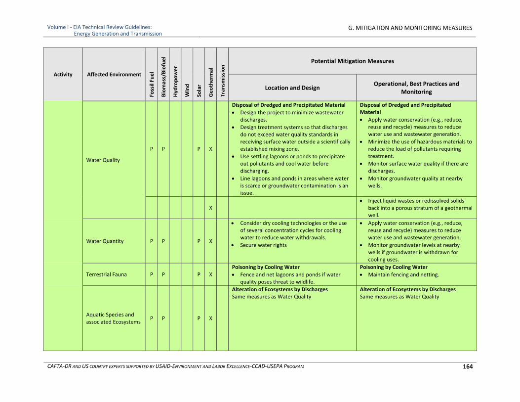
Volume I ‐ EIA Technical Review Guidelines: Energy Generation and Transmission
G. MITIGATION AND MONITORING MEASURES
CAFTA‐DR AND US COUNTRY EXPERTS SUPPORTED BY USAID‐ENVIRONMENT AND LABOR EXCELLENCE‐CCAD‐USEPA PROGRAM 164
Activity Affected Environment
Fossil Fuel
Biomass/Biofuel
Hyd
ropower
Wind
Solar
Geotherm
al
Tran
smission Potential Mitigation Measures
Location and Design Operational, Best Practices and
Monitoring
Water Quality
P P P X
Disposal of Dredged and Precipitated Material
Design the project to minimize wastewater discharges.
Design treatment systems so that discharges do not exceed water quality standards in receiving surface water outside a scientifically established mixing zone.
Use settling lagoons or ponds to precipitate out pollutants and cool water before discharging.
Line lagoons and ponds in areas where water is scarce or groundwater contamination is an issue.
Disposal of Dredged and Precipitated Material
Apply water conservation (e.g., reduce, reuse and recycle) measures to reduce water use and wastewater generation.
Minimize the use of hazardous materials to reduce the load of pollutants requiring treatment.
Monitor surface water quality if there are discharges.
Monitor groundwater quality at nearby wells.
X Inject liquid wastes or redissolved solids
back into a porous stratum of a geothermal well.
Water Quantity P P P X
Consider dry cooling technologies or the use of several concentration cycles for cooling water to reduce water withdrawals.
Secure water rights
Apply water conservation (e.g., reduce, reuse and recycle) measures to reduce water use and wastewater generation.
Monitor groundwater levels at nearby wells if groundwater is withdrawn for cooling uses.
Terrestrial Fauna P P P X Poisoning by Cooling Water
Fence and net lagoons and ponds if water quality poses threat to wildlife.
Poisoning by Cooling Water
Maintain fencing and netting.
Aquatic Species and associated Ecosystems
P P P X
Alteration of Ecosystems by Discharges Same measures as Water Quality
Alteration of Ecosystems by Discharges Same measures as Water Quality
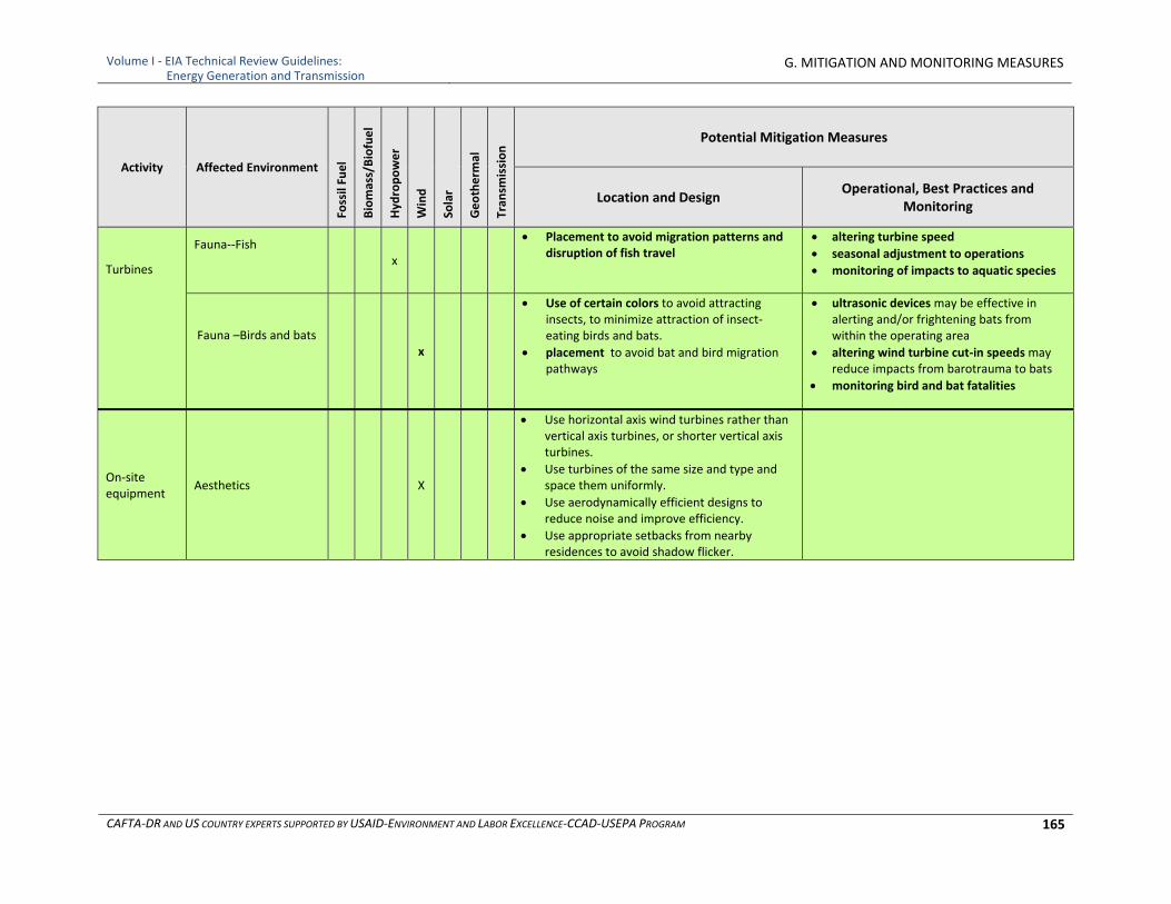
Volume I ‐ EIA Technical Review Guidelines: Energy Generation and Transmission
G. MITIGATION AND MONITORING MEASURES
CAFTA‐DR AND US COUNTRY EXPERTS SUPPORTED BY USAID‐ENVIRONMENT AND LABOR EXCELLENCE‐CCAD‐USEPA PROGRAM 165
Activity Affected Environment
Fossil Fuel
Biomass/Biofuel
Hyd
ropower
Wind
Solar
Geotherm
al
Tran
smission Potential Mitigation Measures
Location and Design Operational, Best Practices and
Monitoring
Turbines
Fauna‐‐Fish
x
Placement to avoid migration patterns and disruption of fish travel
altering turbine speed
seasonal adjustment to operations
monitoring of impacts to aquatic species
Fauna –Birds and bats
x
Use of certain colors to avoid attracting insects, to minimize attraction of insect‐eating birds and bats.
placement to avoid bat and bird migration pathways
ultrasonic devices may be effective in alerting and/or frightening bats from within the operating area
altering wind turbine cut‐in speeds may reduce impacts from barotrauma to bats
monitoring bird and bat fatalities
On‐site equipment
Aesthetics X
Use horizontal axis wind turbines rather than vertical axis turbines, or shorter vertical axis turbines.
Use turbines of the same size and type and space them uniformly.
Use aerodynamically efficient designs to reduce noise and improve efficiency.
Use appropriate setbacks from nearby residences to avoid shadow flicker.
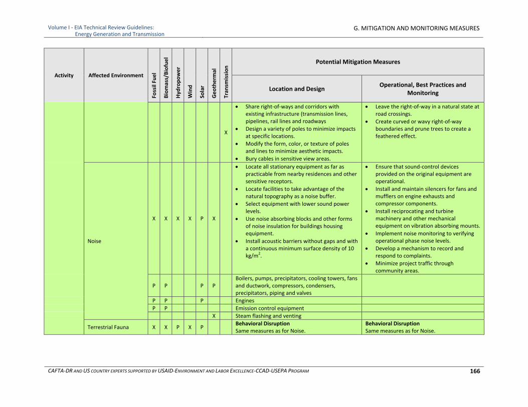
Volume I ‐ EIA Technical Review Guidelines: Energy Generation and Transmission
G. MITIGATION AND MONITORING MEASURES
CAFTA‐DR AND US COUNTRY EXPERTS SUPPORTED BY USAID‐ENVIRONMENT AND LABOR EXCELLENCE‐CCAD‐USEPA PROGRAM 166
Activity Affected Environment
Fossil Fuel
Biomass/Biofuel
Hyd
ropower
Wind
Solar
Geotherm
al
Tran
smission Potential Mitigation Measures
Location and Design Operational, Best Practices and
Monitoring
X
Share right‐of‐ways and corridors with existing infrastructure (transmission lines, pipelines, rail lines and roadways
Design a variety of poles to minimize impacts at specific locations.
Modify the form, color, or texture of poles and lines to minimize aesthetic impacts.
Bury cables in sensitive view areas.
Leave the right‐of‐way in a natural state at road crossings.
Create curved or wavy right‐of‐way boundaries and prune trees to create a feathered effect.
Noise
X X X X P X
Locate all stationary equipment as far as practicable from nearby residences and other sensitive receptors.
Locate facilities to take advantage of the natural topography as a noise buffer.
Select equipment with lower sound power levels.
Use noise absorbing blocks and other forms of noise insulation for buildings housing equipment.
Install acoustic barriers without gaps and with a continuous minimum surface density of 10 kg/m2.
Ensure that sound‐control devices provided on the original equipment are operational.
Install and maintain silencers for fans and mufflers on engine exhausts and compressor components.
Install reciprocating and turbine machinery and other mechanical equipment on vibration absorbing mounts.
Implement noise monitoring to verifying operational phase noise levels.
Develop a mechanism to record and respond to complaints.
Minimize project traffic through community areas.
P P P P Boilers, pumps, precipitators, cooling towers, fans and ductwork, compressors, condensers, precipitators, piping and valves
P P P Engines
P P Emission control equipment
X Steam flashing and venting
Terrestrial Fauna X X P X P Behavioral Disruption Same measures as for Noise.
Behavioral Disruption Same measures as for Noise.
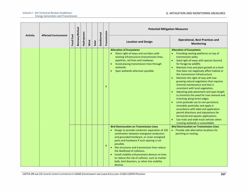
Volume I ‐ EIA Technical Review Guidelines: Energy Generation and Transmission
G. MITIGATION AND MONITORING MEASURES
CAFTA‐DR AND US COUNTRY EXPERTS SUPPORTED BY USAID‐ENVIRONMENT AND LABOR EXCELLENCE‐CCAD‐USEPA PROGRAM 167
Activity Affected Environment
Fossil Fuel
Biomass/Biofuel
Hyd
ropower
Wind
Solar
Geotherm
al
Tran
smission Potential Mitigation Measures
Location and Design Operational, Best Practices and
Monitoring
X
Alteration of Ecosystems
Share right‐of‐ways and corridors with existing infrastructure (transmission lines, pipelines, rail lines and roadways.
Avoid placing transmission lines through wetlands.
Span wetlands wherever possible.
Alteration of Ecosystems
Providing nesting platforms on top of transmission poles.
Seed right‐of‐ways with species favored for forage by wildlife.
Maintain tree and plant growth at a level that does not negatively affect habitat or the transmission infrastructure.
Maintain the right‐of‐way with low‐growing natural vegetation that requires minimal maintenance and that is consistent with local vegetation.
Adjusting pole placement and span length to minimize the need for tree removal and trimming along forest edges
Limit pesticide use to non‐persistent, immobile pesticides and apply in accordance with label and application permit directions and stipulations for terrestrial and aquatic applications.
Use mats and wide‐track vehicles when crossing wetlands is unavoidable.
X
Bird Electrocution on Transmission Lines
Design to provide conductor separation of 150 centimeters between energized conductors and grounded hardware, or cover energized parts and hardware if such spacing is not possible.
Site structures and transmission lines reduce the likelihood of collisions.
Install visibility enhancement devices on lines to reduce the risk of collision, such as marker balls, bird diverters, or other line visibility devices.
Bird Electrocution on Transmission Lines
Provide safe alternative locations for perching or nesting.
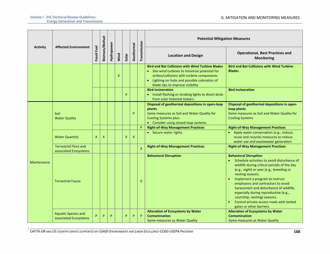
Volume I ‐ EIA Technical Review Guidelines: Energy Generation and Transmission
G. MITIGATION AND MONITORING MEASURES
CAFTA‐DR AND US COUNTRY EXPERTS SUPPORTED BY USAID‐ENVIRONMENT AND LABOR EXCELLENCE‐CCAD‐USEPA PROGRAM 168
Activity Affected Environment
Fossil Fuel
Biomass/Biofuel
Hyd
ropower
Wind
Solar
Geotherm
al
Tran
smission Potential Mitigation Measures
Location and Design Operational, Best Practices and
Monitoring
X
Bird and Bat Collisions with Wind Turbine Blades
Site wind turbines to minimize potential for strikes/collisions with turbine components.
Lighting on hubs and possible coloration of blade tips to improve visibility
Bird and Bat Collisions with Wind Turbine Blades
X Bird Incineration
Install flashing or strobing lights to divert birds from solar heliostat towers.
Bird Incineration
Maintenance
Soil Water Quality
P
Disposal of geothermal depositions in open‐loop plants Same measures as Soil and Water Quality for Cooling Systems plus:
Consider using closed‐loop systems
Disposal of geothermal depositions in open‐loop plants Same measures as Soil and Water Quality for Cooling Systems
P Right‐of‐Way Management Practices Right‐of‐Way Management Practices
Water Quantity X X X X Secure water rights. Apply water conservation (e.g., reduce,
reuse and recycle) measures to reduce water use and wastewater generation.
Terrestrial Flora and associated Ecosystems
X Right‐of‐Way Management Practices Right‐of‐Way Management Practices
Terrestrial Fauna X
Behavioral Disruption Behavioral Disruption
Schedule activities to avoid disturbance of wildlife during critical periods of the day (e.g., night) or year (e.g., breeding or nesting season).
Implement a program to instruct employees and contractors to avoid harassment and disturbance of wildlife, especially during reproductive (e.g., courtship, nesting) seasons.
Control private access roads with locked gates or other barriers.
Aquatic Species and associated Ecosystems
P P P P P P Alteration of Ecosystems by Water Contamination Same measures as Water Quality
Alteration of Ecosystems by Water Contamination Same measures as Water Quality
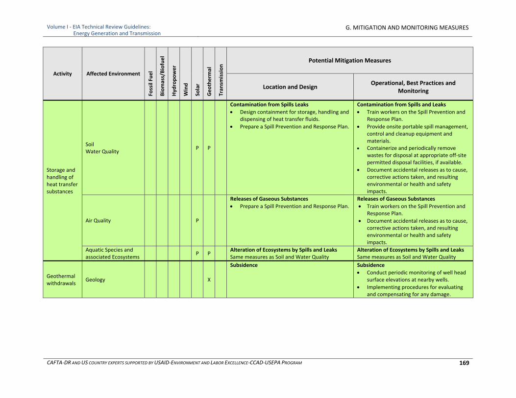
Volume I ‐ EIA Technical Review Guidelines: Energy Generation and Transmission
G. MITIGATION AND MONITORING MEASURES
CAFTA‐DR AND US COUNTRY EXPERTS SUPPORTED BY USAID‐ENVIRONMENT AND LABOR EXCELLENCE‐CCAD‐USEPA PROGRAM 169
Activity Affected Environment
Fossil Fuel
Biomass/Biofuel
Hyd
ropower
Wind
Solar
Geotherm
al
Tran
smission Potential Mitigation Measures
Location and Design Operational, Best Practices and
Monitoring
Storage and handling of heat transfer substances
Soil Water Quality
P P
Contamination from Spills Leaks
Design containment for storage, handling and dispensing of heat transfer fluids.
Prepare a Spill Prevention and Response Plan.
Contamination from Spills and Leaks
Train workers on the Spill Prevention and Response Plan.
Provide onsite portable spill management, control and cleanup equipment and materials.
Containerize and periodically remove wastes for disposal at appropriate off‐site permitted disposal facilities, if available.
Document accidental releases as to cause, corrective actions taken, and resulting environmental or health and safety impacts.
Air Quality P
Releases of Gaseous Substances
Prepare a Spill Prevention and Response Plan.
Releases of Gaseous Substances
Train workers on the Spill Prevention and Response Plan.
Document accidental releases as to cause, corrective actions taken, and resulting environmental or health and safety impacts.
Aquatic Species and associated Ecosystems
P P Alteration of Ecosystems by Spills and Leaks Same measures as Soil and Water Quality
Alteration of Ecosystems by Spills and Leaks Same measures as Soil and Water Quality
Geothermal withdrawals
Geology X
Subsidence Subsidence
Conduct periodic monitoring of well head surface elevations at nearby wells.
Implementing procedures for evaluating and compensating for any damage.
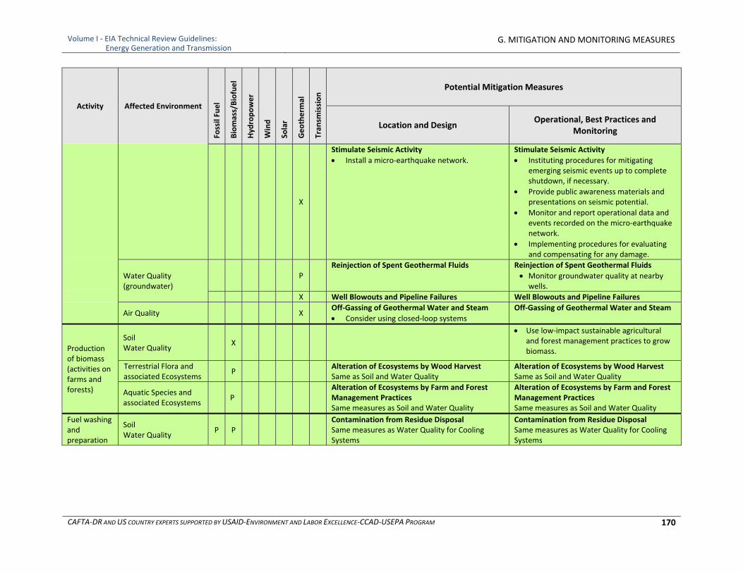
Volume I ‐ EIA Technical Review Guidelines: Energy Generation and Transmission
G. MITIGATION AND MONITORING MEASURES
CAFTA‐DR AND US COUNTRY EXPERTS SUPPORTED BY USAID‐ENVIRONMENT AND LABOR EXCELLENCE‐CCAD‐USEPA PROGRAM 170
Activity Affected Environment
Fossil Fuel
Biomass/Biofuel
Hyd
ropower
Wind
Solar
Geotherm
al
Tran
smission Potential Mitigation Measures
Location and Design Operational, Best Practices and
Monitoring
X
Stimulate Seismic Activity
Install a micro‐earthquake network.
Stimulate Seismic Activity
Instituting procedures for mitigating emerging seismic events up to complete shutdown, if necessary.
Provide public awareness materials and presentations on seismic potential.
Monitor and report operational data and events recorded on the micro‐earthquake network.
Implementing procedures for evaluating and compensating for any damage.
Water Quality (groundwater)
P Reinjection of Spent Geothermal Fluids Reinjection of Spent Geothermal Fluids
Monitor groundwater quality at nearby wells.
X Well Blowouts and Pipeline Failures Well Blowouts and Pipeline Failures
Air Quality X Off‐Gassing of Geothermal Water and Steam
Consider using closed‐loop systems
Off‐Gassing of Geothermal Water and Steam
Production of biomass (activities on farms and forests)
Soil Water Quality
X
Use low‐impact sustainable agricultural and forest management practices to grow biomass.
Terrestrial Flora and associated Ecosystems
P Alteration of Ecosystems by Wood Harvest Same as Soil and Water Quality
Alteration of Ecosystems by Wood Harvest Same as Soil and Water Quality
Aquatic Species and associated Ecosystems
P
Alteration of Ecosystems by Farm and Forest Management Practices Same measures as Soil and Water Quality
Alteration of Ecosystems by Farm and Forest Management Practices Same measures as Soil and Water Quality
Fuel washing and preparation
Soil Water Quality
P P Contamination from Residue Disposal
Same measures as Water Quality for Cooling Systems
Contamination from Residue Disposal Same measures as Water Quality for Cooling Systems
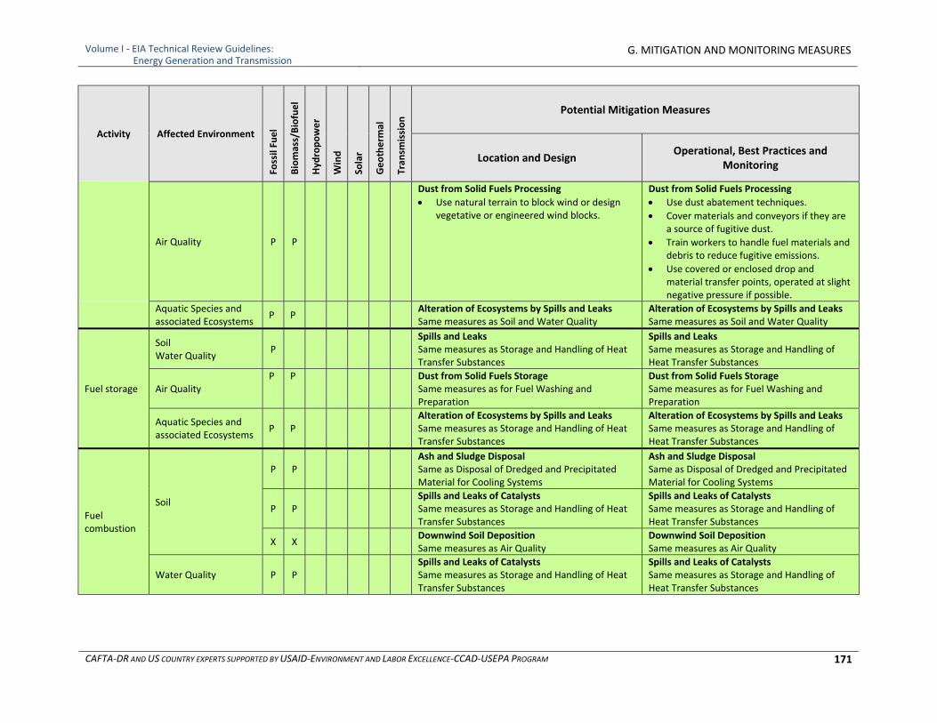
Volume I ‐ EIA Technical Review Guidelines: Energy Generation and Transmission
G. MITIGATION AND MONITORING MEASURES
CAFTA‐DR AND US COUNTRY EXPERTS SUPPORTED BY USAID‐ENVIRONMENT AND LABOR EXCELLENCE‐CCAD‐USEPA PROGRAM 171
Activity Affected Environment
Fossil Fuel
Biomass/Biofuel
Hyd
ropower
Wind
Solar
Geotherm
al
Tran
smission Potential Mitigation Measures
Location and Design Operational, Best Practices and
Monitoring
Air Quality P P
Dust from Solid Fuels Processing
Use natural terrain to block wind or design vegetative or engineered wind blocks.
Dust from Solid Fuels Processing
Use dust abatement techniques.
Cover materials and conveyors if they are a source of fugitive dust.
Train workers to handle fuel materials and debris to reduce fugitive emissions.
Use covered or enclosed drop and material transfer points, operated at slight negative pressure if possible.
Aquatic Species and associated Ecosystems
P P Alteration of Ecosystems by Spills and Leaks
Same measures as Soil and Water Quality Alteration of Ecosystems by Spills and Leaks Same measures as Soil and Water Quality
Fuel storage
Soil Water Quality
P Spills and Leaks
Same measures as Storage and Handling of Heat Transfer Substances
Spills and Leaks Same measures as Storage and Handling of Heat Transfer Substances
Air Quality P P Dust from Solid Fuels Storage
Same measures as for Fuel Washing and Preparation
Dust from Solid Fuels Storage Same measures as for Fuel Washing and Preparation
Aquatic Species and associated Ecosystems
P P Alteration of Ecosystems by Spills and Leaks
Same measures as Storage and Handling of Heat Transfer Substances
Alteration of Ecosystems by Spills and Leaks Same measures as Storage and Handling of Heat Transfer Substances
Fuel combustion
Soil
P P Ash and Sludge Disposal Same as Disposal of Dredged and Precipitated Material for Cooling Systems
Ash and Sludge Disposal Same as Disposal of Dredged and Precipitated Material for Cooling Systems
P P Spills and Leaks of Catalysts Same measures as Storage and Handling of Heat Transfer Substances
Spills and Leaks of Catalysts Same measures as Storage and Handling of Heat Transfer Substances
X X Downwind Soil Deposition Same measures as Air Quality
Downwind Soil Deposition Same measures as Air Quality
Water Quality P P Spills and Leaks of Catalysts Same measures as Storage and Handling of Heat Transfer Substances
Spills and Leaks of Catalysts Same measures as Storage and Handling of Heat Transfer Substances
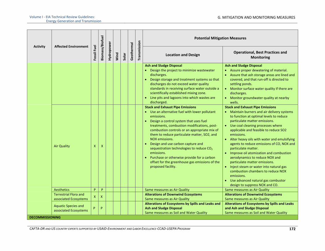
Volume I ‐ EIA Technical Review Guidelines: Energy Generation and Transmission
G. MITIGATION AND MONITORING MEASURES
CAFTA‐DR AND US COUNTRY EXPERTS SUPPORTED BY USAID‐ENVIRONMENT AND LABOR EXCELLENCE‐CCAD‐USEPA PROGRAM 172
Activity Affected Environment
Fossil Fuel
Biomass/Biofuel
Hyd
ropower
Wind
Solar
Geotherm
al
Tran
smission Potential Mitigation Measures
Location and Design Operational, Best Practices and
Monitoring
Ash and Sludge Disposal
Design the project to minimize wastewater discharges.
Design storage and treatment systems so that discharges do not exceed water quality standards in receiving surface water outside a scientifically established mixing zone.
Line pits and lagoons into which wastes are discharged.
Ash and Sludge Disposal
Assure proper dewatering of material.
Assure that ash storage areas are lined and covered, and that run‐off is directed to settling ponds.
Monitor surface water quality if there are discharges.
Monitor groundwater quality at nearby wells.
Air Quality X X
Stack and Exhaust Pipe Emissions
Use an alternative fuel with lower pollutant emissions.
Design a control system that uses fuel treatments, combustion modifications, post‐combustion controls or an appropriate mix of them to reduce particulate matter, SO2, and NOX emissions.
Design and use carbon capture and sequestration technologies to reduce CO2 emissions.
Purchase or otherwise provide for a carbon offset for the greenhouse gas emissions of the proposed facility.
Stack and Exhaust Pipe Emissions
Maintain burners and air delivery systems to function at optimal levels to reduce particulate matter emissions.
Use coal cleaning processes where applicable and feasible to reduce SO2 emissions.
Alter heavy oils with water and emulsifying agents to reduce emissions of CO, NOX and particulate matter.
Improve oil atomization and combustion aerodynamics to reduce NOX and particulate matter emissions.
Inject steam or water into natural gas combustion chambers to reduce NOX emissions.
Use advanced natural gas combustor design to suppress NOX and CO.
Aesthetics P P Same measures as Air Quality Same measures as Air Quality
Terrestrial Flora and associated Ecosystems
X X Alterations of Downwind Ecosystems Same measures as Air Quality
Alterations of Downwind Ecosystems Same measures as Air Quality
Aquatic Species and associated Ecosystems
P P Alterations of Ecosystems by Spills and Leaks and Ash and Sludge Disposal Same measures as Soil and Water Quality
Alterations of Ecosystems by Spills and Leaks and Ash and Sludge Disposal Same measures as Soil and Water Quality
DECOMMISSIONING
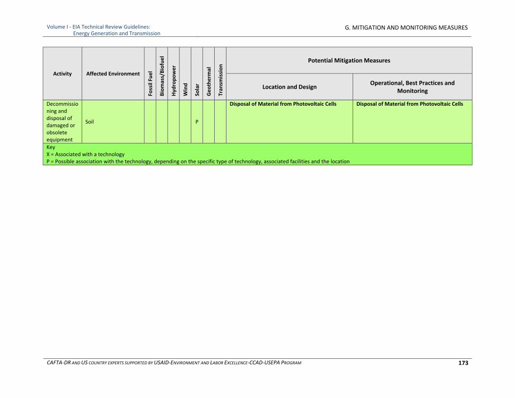
Volume I ‐ EIA Technical Review Guidelines: Energy Generation and Transmission
G. MITIGATION AND MONITORING MEASURES
CAFTA‐DR AND US COUNTRY EXPERTS SUPPORTED BY USAID‐ENVIRONMENT AND LABOR EXCELLENCE‐CCAD‐USEPA PROGRAM 173
Activity Affected Environment
Fossil Fuel
Biomass/Biofuel
Hyd
ropower
Wind
Solar
Geotherm
al
Tran
smission Potential Mitigation Measures
Location and Design Operational, Best Practices and
Monitoring
Decommissioning and disposal of damaged or obsolete equipment
Soil P
Disposal of Material from Photovoltaic Cells Disposal of Material from Photovoltaic Cells
Key X = Associated with a technology P = Possible association with the technology, depending on the specific type of technology, associated facilities and the location
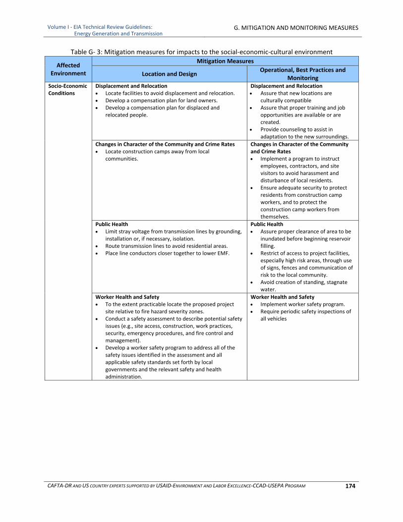
Volume I ‐ EIA Technical Review Guidelines: Energy Generation and Transmission
G. MITIGATION AND MONITORING MEASURES
CAFTA‐DR AND US COUNTRY EXPERTS SUPPORTED BY USAID‐ENVIRONMENT AND LABOR EXCELLENCE‐CCAD‐USEPA PROGRAM 174
Table G‐ 3: Mitigation measures for impacts to the social‐economic‐cultural environment
Affected Environment
Mitigation Measures
Location and Design Operational, Best Practices and
Monitoring Socio‐Economic Conditions
Displacement and Relocation Locate facilities to avoid displacement and relocation. Develop a compensation plan for land owners. Develop a compensation plan for displaced and
relocated people.
Displacement and Relocation Assure that new locations are
culturally compatible Assure that proper training and job
opportunities are available or are created.
Provide counseling to assist in adaptation to the new surroundings.
Changes in Character of the Community and Crime Rates Locate construction camps away from local
communities.
Changes in Character of the Community and Crime Rates Implement a program to instruct
employees, contractors, and site visitors to avoid harassment and disturbance of local residents.
Ensure adequate security to protect residents from construction camp workers, and to protect the construction camp workers from themselves.
Public Health Limit stray voltage from transmission lines by grounding,
installation or, if necessary, isolation. Route transmission lines to avoid residential areas. Place line conductors closer together to lower EMF.
Public Health Assure proper clearance of area to be
inundated before beginning reservoir filling.
Restrict of access to project facilities, especially high risk areas, through use of signs, fences and communication of risk to the local community.
Avoid creation of standing, stagnate water.
Worker Health and Safety To the extent practicable locate the proposed project
site relative to fire hazard severity zones. Conduct a safety assessment to describe potential safety
issues (e.g., site access, construction, work practices, security, emergency procedures, and fire control and management).
Develop a worker safety program to address all of the safety issues identified in the assessment and all applicable safety standards set forth by local governments and the relevant safety and health administration.
Worker Health and Safety Implement worker safety program. Require periodic safety inspections of
all vehicles
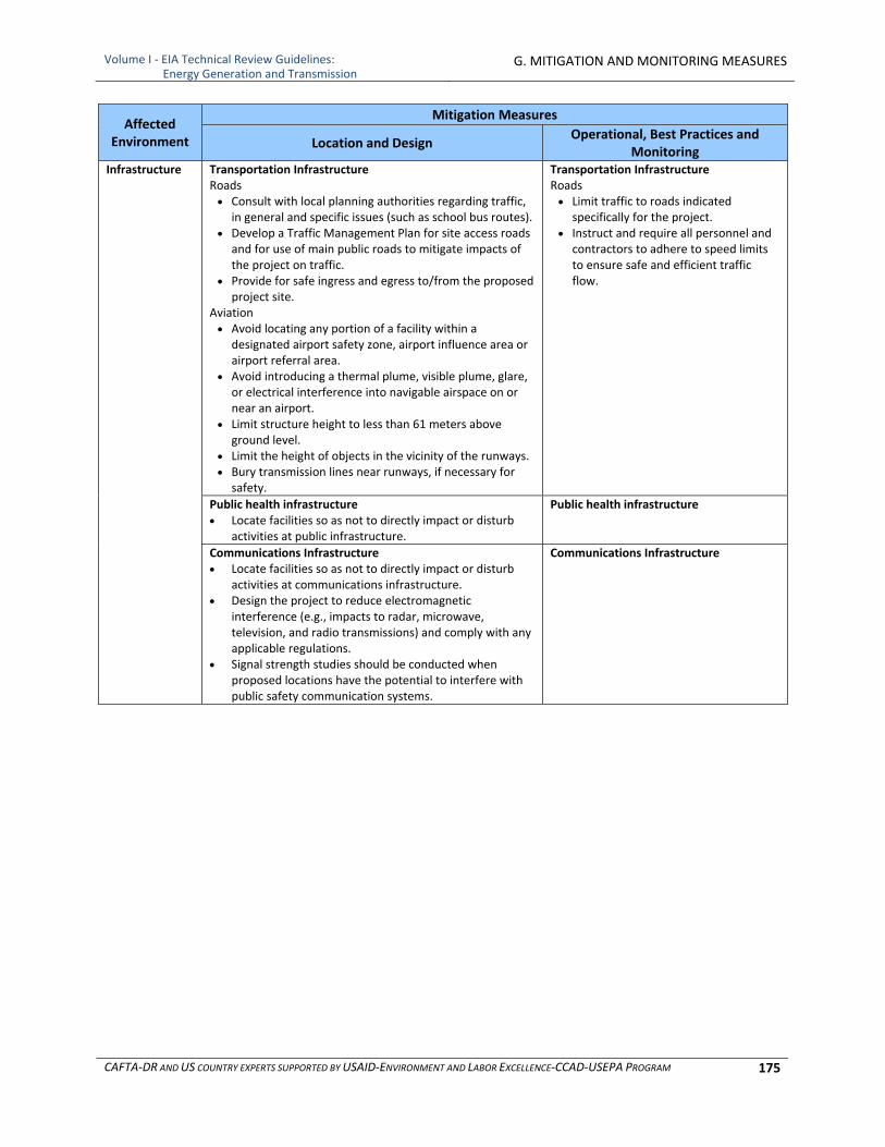
Volume I ‐ EIA Technical Review Guidelines: Energy Generation and Transmission
G. MITIGATION AND MONITORING MEASURES
CAFTA‐DR AND US COUNTRY EXPERTS SUPPORTED BY USAID‐ENVIRONMENT AND LABOR EXCELLENCE‐CCAD‐USEPA PROGRAM 175
Affected Environment
Mitigation Measures
Location and Design Operational, Best Practices and
Monitoring Infrastructure Transportation Infrastructure
Roads Consult with local planning authorities regarding traffic,
in general and specific issues (such as school bus routes). Develop a Traffic Management Plan for site access roads
and for use of main public roads to mitigate impacts of the project on traffic.
Provide for safe ingress and egress to/from the proposed project site.
Aviation Avoid locating any portion of a facility within a
designated airport safety zone, airport influence area or airport referral area.
Avoid introducing a thermal plume, visible plume, glare, or electrical interference into navigable airspace on or near an airport.
Limit structure height to less than 61 meters above ground level.
Limit the height of objects in the vicinity of the runways. Bury transmission lines near runways, if necessary for
safety.
Transportation Infrastructure Roads Limit traffic to roads indicated
specifically for the project. Instruct and require all personnel and
contractors to adhere to speed limits to ensure safe and efficient traffic flow.
Public health infrastructure Locate facilities so as not to directly impact or disturb
activities at public infrastructure.
Public health infrastructure
Communications Infrastructure Locate facilities so as not to directly impact or disturb
activities at communications infrastructure. Design the project to reduce electromagnetic
interference (e.g., impacts to radar, microwave, television, and radio transmissions) and comply with any applicable regulations.
Signal strength studies should be conducted when proposed locations have the potential to interfere with public safety communication systems.
Communications Infrastructure
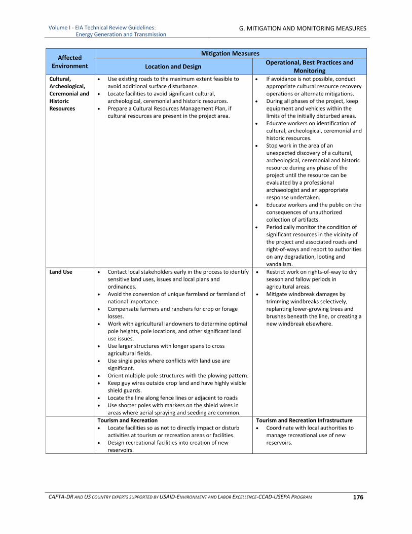
Volume I ‐ EIA Technical Review Guidelines: Energy Generation and Transmission
G. MITIGATION AND MONITORING MEASURES
CAFTA‐DR AND US COUNTRY EXPERTS SUPPORTED BY USAID‐ENVIRONMENT AND LABOR EXCELLENCE‐CCAD‐USEPA PROGRAM 176
Affected Environment
Mitigation Measures
Location and Design Operational, Best Practices and
Monitoring Cultural, Archeological, Ceremonial and Historic Resources
Use existing roads to the maximum extent feasible to avoid additional surface disturbance.
Locate facilities to avoid significant cultural, archeological, ceremonial and historic resources.
Prepare a Cultural Resources Management Plan, if cultural resources are present in the project area.
If avoidance is not possible, conduct appropriate cultural resource recovery operations or alternate mitigations.
During all phases of the project, keep equipment and vehicles within the limits of the initially disturbed areas.
Educate workers on identification of cultural, archeological, ceremonial and historic resources.
Stop work in the area of an unexpected discovery of a cultural, archeological, ceremonial and historic resource during any phase of the project until the resource can be evaluated by a professional archaeologist and an appropriate response undertaken.
Educate workers and the public on the consequences of unauthorized collection of artifacts.
Periodically monitor the condition of significant resources in the vicinity of the project and associated roads and right‐of‐ways and report to authorities on any degradation, looting and vandalism.
Land Use Contact local stakeholders early in the process to identify sensitive land uses, issues and local plans and ordinances.
Avoid the conversion of unique farmland or farmland of national importance.
Compensate farmers and ranchers for crop or forage losses.
Work with agricultural landowners to determine optimal pole heights, pole locations, and other significant land use issues.
Use larger structures with longer spans to cross agricultural fields.
Use single poles where conflicts with land use are significant.
Orient multiple‐pole structures with the plowing pattern. Keep guy wires outside crop land and have highly visible
shield guards. Locate the line along fence lines or adjacent to roads Use shorter poles with markers on the shield wires in
areas where aerial spraying and seeding are common.
Restrict work on rights‐of‐way to dry season and fallow periods in agricultural areas.
Mitigate windbreak damages by trimming windbreaks selectively, replanting lower‐growing trees and brushes beneath the line, or creating a new windbreak elsewhere.
Tourism and Recreation Locate facilities so as not to directly impact or disturb
activities at tourism or recreation areas or facilities. Design recreational facilities into creation of new
reservoirs.
Tourism and Recreation Infrastructure Coordinate with local authorities to
manage recreational use of new reservoirs.
Volume I ‐ EIA Technical Review Guidelines: Energy Generation and Transmission
G. MITIGATION AND MONITORING MEASURES
CAFTA‐DR AND US COUNTRY EXPERTS SUPPORTED BY USAID‐ENVIRONMENT AND LABOR EXCELLENCE‐CCAD‐USEPA PROGRAM 177
2 SPECIFIC MITIGATION MEASURES
The following subsections provide additional information on some mitigation measures, for which the information in Tables G‐1 through G‐3 may not be sufficient. The measures elaborated upon include:
Seismic events associated with geothermal developments
Process and wastewater discharges
Air emissions from fossil fuel‐ and biomass‐fired plants
Noise
Transmission lines The elaboration on these mitigation measures in no way indicates that they are more important than the other measures in Tables G‐1 through G‐3. They are elaborated upon here only because the EIA reviewer may need more information than is provided in the Tables to understand the application of the measures.
2.1 Seismic Events Associated with Geothermal Developments
Geothermal developments have been identified as inducing seismic events. Induced seismicity, can be mitigated, if not overcome, using modern geoscientific methods to thoroughly characterize potential reservoir target areas before drilling and stimulation begin. With current technology, it appears feasible that the number and magnitude of these induced events can be managed by undertaking the following actions:
Collect stress data, background seismicity, and geology data prior to actual field stimulation
Enter this data into predictive stimulation models to estimate and forecast potential induced seismicity magnitude and potential radius of seismicity
Install ground motion sensors
Create public awareness of seismic potential
Monitoring and reporting of operational data and events
Instituting procedures for mitigating emerging seismic events up to complete shutdown, if necessary
Implement procedures for evaluating and compensating for any damage
2.2 Process and Wastewater Discharges
Project‐specific performance levels for wastewater effluents should be set prior to designing wastewater treatment systems. The standards should comply with national standards, if they exist, and take into consideration the quality and volume of the receiving waters. Additional considerations that should be included in the setting of project‐specific performance levels for wastewater effluents include:
Process wastewater treatment standards should be consistent with applicable requirements for a specific industry or, where there are no industry‐specific guidelines, should reference the effluent quality guidelines of an industry sector with suitably analogous processes and effluents
Compliance with national or local standards for sanitary wastewater discharges or, in their absence, indicative guideline values applicable to sanitary wastewater discharges as shown in Table G‐4 or developed from standards presented for a range of countries and international organizations in Volume II, Appendix C
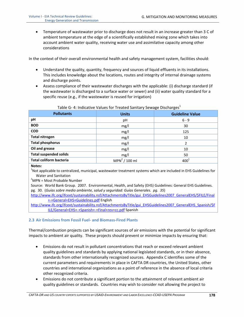
Volume I ‐ EIA Technical Review Guidelines: Energy Generation and Transmission
G. MITIGATION AND MONITORING MEASURES
CAFTA‐DR AND US COUNTRY EXPERTS SUPPORTED BY USAID‐ENVIRONMENT AND LABOR EXCELLENCE‐CCAD‐USEPA PROGRAM 178
Temperature of wastewater prior to discharge does not result in an increase greater than 3 C of ambient temperature at the edge of a scientifically established mixing zone which takes into account ambient water quality, receiving water use and assimilative capacity among other considerations
In the context of their overall environmental health and safety management system, facilities should:
Understand the quality, quantity, frequency and sources of liquid effluents in its installations. This includes knowledge about the locations, routes and integrity of internal drainage systems and discharge points.
Assess compliance of their wastewater discharges with the applicable: (i) discharge standard (if the wastewater is discharged to a surface water or sewer) and (ii) water quality standard for a specific reuse (e.g., if the wastewater is reused for irrigation)
Table G‐ 4: Indicative Values for Treated Sanitary Sewage Discharges1
Pollutants Units Guideline Value pH pH 6 ‐ 9
BOD mg/l 30
COD mg/l 125
Total nitrogen mg/l 10
Total phosphorus mg/l 2
Oil and grease mg/l 10
Total suspended solids mg/l 50
Total coliform bacteria MPN2 / 100 ml 4001
Notes: 1Not applicable to centralized, municipal, wastewater treatment systems which are included in EHS Guidelines for
Water and Sanitation 2MPN = Most Probable Number Source: World Bank Group. 2007. Environmental, Health, and Safety (EHS) Guidelines: General EHS Guidelines. pg. 30. (Guías sobre medio ambiente, salud y seguridad: Guías Generales. pg. 35) http://www.ifc.org/ifcext/sustainability.nsf/AttachmentsByTitle/gui_EHSGuidelines2007_GeneralEHS/$FILE/Final
+‐+General+EHS+Guidelines.pdf English http://www.ifc.org/ifcext/sustainability.nsf/AttachmentsByTitle/gui_EHSGuidelines2007_GeneralEHS_Spanish/$F
ILE/General+EHS+‐+Spanish+‐+Final+rev+cc.pdf Spanish
2.3 Air Emissions from Fossil Fuel‐ and Biomass‐Fired Plants
Thermal/combustion projects can be significant sources of air emissions with the potential for significant impacts to ambient air quality. These projects should prevent or minimize impacts by ensuring that:
Emissions do not result in pollutant concentrations that reach or exceed relevant ambient quality guidelines and standards by applying national legislated standards, or in their absence, standards from other internationally recognized sources. Appendix C identifies some of the current parameters and requirements in place in CAFTA DR countries, the United States, other countries and international organizations as a point of reference in the absence of local criteria other recognized criteria.
Emissions do not contribute a significant portion to the attainment of relevant ambient air quality guidelines or standards. Countries may wish to consider not allowing the project to

Volume I ‐ EIA Technical Review Guidelines: Energy Generation and Transmission
G. MITIGATION AND MONITORING MEASURES
CAFTA‐DR AND US COUNTRY EXPERTS SUPPORTED BY USAID‐ENVIRONMENT AND LABOR EXCELLENCE‐CCAD‐USEPA PROGRAM 179
consume all the potential for air emissions in the airshed, so as to allow additional, future sustainable development in the same airshed.
Facilities or projects located within poor quality air sheds, and within or next to areas established as ecologically sensitive (e.g., national parks), should ensure that any increase in pollution levels is as small as feasible, and amounts to a fraction of the applicable short‐term and annual average air quality guidelines or standards as established in the project‐specific environmental assessment. Suitable measures may also include the relocation of significant sources of emissions outside the air shed in question, use of cleaner fuels or technologies, application of comprehensive pollution control measures, offset activities at installations controlled by the project sponsor or other facilities within the same air shed, and buy‐down of emissions within the same air shed. Specific provisions for minimizing emissions and their impacts in poor air quality or ecologically sensitive air sheds should be established on a project‐by‐project or industry‐specific basis. Offset provisions outside the immediate control of the project sponsor or buy‐downs should be monitored and enforced by the local agency responsible for granting and monitoring emission permits. Such provisions should be in place prior to final commissioning of the facility / project. Where possible, facilities and projects should avoid, minimize, and control adverse impacts to human health, safety, and the environment from air emissions through a combination of:
Energy use efficiency
Process modification
Selection of fuels or other materials, the processing of which may result in less polluting emissions
Application of emissions control techniques. The selected prevention and control techniques may include one or more methods of treatment depending on:
Regulatory requirements
Significance of the source
Location of the emitting facility relative to other sources
Location of sensitive receptors
Existing ambient air quality, and potential for degradation of the air shed from a proposed project
Technical feasibility and cost effectiveness of the available options for prevention, control, and release of emissions.
The main pollutants from thermal/combustion projects are particulate matter (PM), sulfur dioxide (SO2), nitrogen oxides (NOX) and carbon dioxide (CO2). Control techniques for these pollutants generally fall into three broad categories:
Fuel substitution/treatment: burning a cleaner fuel.
Combustion modification: any physical or operational change in the furnace or boiler and is applied primarily for NOX control purposes, although for small units, some reduction in PM emissions may be available through improved combustion practice.
Post‐combustion control: a device placed after the combustion of the fuel to control emissions of PM, SO2, and NOX.
Volume I ‐ EIA Technical Review Guidelines: Energy Generation and Transmission
G. MITIGATION AND MONITORING MEASURES
CAFTA‐DR AND US COUNTRY EXPERTS SUPPORTED BY USAID‐ENVIRONMENT AND LABOR EXCELLENCE‐CCAD‐USEPA PROGRAM 180
Fuel substitution involves burning a cleaner fuel. Among the fossil fuels, the cleanest burning fuel is natural gas, followed by diesel then oil and then by coal. The emissions of concern from natural gas and are primarily NOX and CO2. In the generation of power, natural gas is used almost exclusively for powering of gas turbines. The following subsections discuss the mitigation measures for reducing emissions via combustion modification and post‐combustion control for each of the pollutants of concern.
2.3.1 Particulate Matter
Particulate matter can be a problem at coal‐, biomass‐ and oil‐fired plants as well as with diesel engines. The principal control techniques for PM are combustion modifications (applicable to small stoker‐fired boilers) and post‐combustion methods (applicable to most boiler types and sizes).
2.3.1.1 Combustion Modifications
PM emissions from coal‐ and biomass‐fired plants can be reduced by employing good combustion practices such as operating within the recommended load ranges, controlling the rate of load changes, and ensuring steady, uniform fuel feed. Proper design and operation of the combustion air delivery systems can also minimize PM emissions. For biomass more advanced combustion modifications, such as the whole‐tree burner (which has three successive combustion stages) and the gasifier/combustion turbine combination, should generate much lower emissions, perhaps comparable to those of power plants fueled by natural gas. Control of PM emissions from oil‐fired plants is accomplished by improving burner servicing and improving oil atomization and combustion aerodynamics. Optimization of combustion aerodynamics using a flame retention device, swirl, and/or recirculation is considered effective toward achieving the triple goals of low PM emissions, low NOX emissions and high thermal efficiency. Large utility boilers are generally well‐designed and well‐maintained so that soot and condensable organic compound emissions are minimized. Particulate matter emissions are more a result of emitted fly ash with a carbon component in such units. Therefore, post‐combustion controls may be used to reduce PM emissions from these sources.
2.3.1.2 Post‐Combustion Controls
Post‐combustion control of PM emissions from coal‐, biomass‐ and oil‐fired plants can be accomplished by using one or more or the following particulate control devices:
Electrostatic precipitator
Fabric filter (or baghouse)
Wet scrubber
Cyclone or multiclone collector
Side stream separator (only one not mentioned by previous version as applying to biomass) Electrostatic precipitators (ESPs) are commonly used in oil‐fired power plants. Older precipitators, usually small, typically remove 40 to 60 percent of the emitted PM. Because of the low ash content of the oil, greater collection efficiency may not be required. Currently, new or rebuilt ESPs can achieve collection efficiencies of up to 90 percent.
Volume I ‐ EIA Technical Review Guidelines: Energy Generation and Transmission
G. MITIGATION AND MONITORING MEASURES
CAFTA‐DR AND US COUNTRY EXPERTS SUPPORTED BY USAID‐ENVIRONMENT AND LABOR EXCELLENCE‐CCAD‐USEPA PROGRAM 181
Electrostatic precipitation technology is applicable to a variety of combustion sources. Because of their modular design, ESPs can be applied to a wide range of system sizes and should have no adverse effect on combustion system performance. The operating parameters that influence ESP performance include fly ash mass loading, particle size distribution, fly ash electrical resistivity, and precipitator voltage and current. Other factors that determine ESP collection efficiency are collection plate area, gas flow velocity, and cleaning cycle. Data for ESPs applied to coal‐fired sources show fractional collection efficiencies greater than 99 percent for fine (less than 0.1 micrometer) and coarse particles (greater than 10 micrometers). These data show a reduction in collection efficiency for particle diameters between 0.1 and 10 micrometers. New ESPs can achieve collection efficiencies of up to 90 percent for oil‐fired plants. The efficiency is lower because of the low ash content of the oil, so that an ESP operating at 90% efficiency at an oil‐fired plant is still emitting less PM than one operating at 99% efficiency at a coal‐fired plant. In fabric filtration, a number of filtering elements (bags) along with a bag cleaning system are contained in a main shell structure incorporating dust hoppers. The particulate removal efficiency of fabric filters is dependent on a variety of particle and operational characteristics. Particle characteristics that affect the collection efficiency include particle size distribution, particle cohesion characteristics, and particle electrical resistivity. Operational parameters that affect fabric filter collection efficiency include air‐to‐cloth ratio, operating pressure loss, cleaning sequence, interval between cleanings, cleaning method, and cleaning intensity. The structure of the fabric filter, filter composition, and bag properties also affect collection efficiency. Collection efficiencies of baghouses may be more than 99 percent. Wet scrubbers, including Venturi and flooded disc scrubbers, tray or tower units, turbulent contact absorbers, or high‐pressure spray impingement scrubbers are applicable for PM as well as SO2 control on oil‐, coal‐ and biomass fired plants. Scrubber collection efficiency depends on particle size distribution, gas side pressure drop through the scrubber, and water (or scrubbing liquor) pressure, and can range between 95 and 99 percent for a 2‐micron particle. Cyclone separators can be installed singly, in series, or grouped as in a multicyclone or multiclone collector. These devices are referred to as mechanical collectors and are often used as a precollector upstream of an ESP, fabric filter, or wet scrubber so that these devices can be specified for lower particle loadings to reduce capital and/or operating costs. The collection efficiency of a mechanical collector depends strongly on the effective aerodynamic particle diameter. Although these devices will reduce PM emissions from coal combustion, they are relatively ineffective for collection of particles less than 10 micron (PM10). The typical overall collection efficiency for mechanical collectors ranges from 90 to 95 percent. In oil‐fired plants, cyclones are primarily useful in controlling particulate matter generated during soot blowing, during upset conditions, or when very dirty heavy oil is fired. For these situations, high‐efficiency cyclonic collectors can achieve up to 85 percent control of particulate. Under normal firing conditions, or when clean oil is combusted, cyclonic collectors are not nearly so effective because of the high percentage of small particles (less than 3 micrometers in diameter) emitted. The side‐stream separator combines a multicyclone and a small pulse‐jet baghouse to more efficiently collect small‐diameter particles that are difficult to capture by a mechanical collector alone. Most applications to date for side‐stream separators have been on small stoker coal‐fired boilers. Atmospheric fluidized bed combustion (AFBC) coal‐fired boilers may tax conventional particulate control systems. The particulate mass concentration exiting AFBC boilers is typically 2 to 4 times higher than
Volume I ‐ EIA Technical Review Guidelines: Energy Generation and Transmission
G. MITIGATION AND MONITORING MEASURES
CAFTA‐DR AND US COUNTRY EXPERTS SUPPORTED BY USAID‐ENVIRONMENT AND LABOR EXCELLENCE‐CCAD‐USEPA PROGRAM 182
pulverized coal boilers. AFBC particles are also, on average, smaller in size, and irregularly shaped with higher surface area and porosity relative to pulverized coal ashes. The effect is a higher pressure drop. The AFBC ash is more difficult to collect in ESPs than pulverized coal ash because AFBC ash has a higher electrical resistivity and the use of multiclones for recycling, inherent with the AFBC process, tends to reduce exit gas stream particulate size.
2.3.2 Sulfur Dioxide Control
Fuel treatment is possible with coal to reduce SO2. It involves using physical, chemical, or biological processes to wash the coal before it is burned. All other control technologies for SO2 are post‐combustion technologies. Post‐combustion flue gas desulfurization (FGD) techniques can remove SO2 formed during combustion by using an alkaline reagent to absorb in the flue gas and produce a sodium or a calcium sulfate compound. These solid sulfate compounds are then removed in downstream equipment. FGD technologies are categorized as wet, semi‐dry, or dry depending on the state of the reagent as it leaves the absorber vessel. These processes are either regenerable (such that the reagent material can be treated and reused) or non‐regenerable (in which case all waste streams are de‐watered and discarded). Wet regenerable FGD processes are attractive because they have the potential for better than 95 percent sulfur removal efficiency, have minimal waste water discharges, and produce a saleable sulfur product. Some of the current non‐regenerable calcium‐based processes can, however, produce a saleable gypsum product. To date, wet systems are the most commonly applied. Wet systems generally use alkali slurries as the SO2 absorbent medium and can be designed to remove greater than 90 percent of the incoming SO2. Lime/limestone scrubbers, sodium scrubbers, and dual alkali scrubbers are among the commercially proven wet FGD systems. The effectiveness of these devices depends not only on control device design but also on operating variables. Particulate reduction of more than 99 percent is possible with wet scrubbers, but fly ash is often collected by upstream ESPs or baghouses, to avoid erosion of the desulfurization equipment and possible interference with FGD process reactions. Also, the volume of scrubber sludge is reduced with separate fly ash removal, and contamination of the reagents and by‐products is prevented. The lime and limestone wet scrubbing process uses a slurry of calcium oxide or limestone to absorb SO2 in a wet scrubber. Control efficiencies in excess of 91 percent for lime and 94 percent for limestone over extended periods are possible. Sodium scrubbing processes generally employ a wet scrubbing solution of sodium hydroxide or sodium carbonate to absorb SO2 from the flue gas. Sodium scrubbers are generally limited to smaller sources because of high reagent costs and can have SO2 removal efficiencies of up to 96.2 percent. The double or dual alkali system uses a clear sodium alkali solution for SO2 removal followed by a regeneration step using lime or limestone to recover the sodium alkali and produce a calcium sulfite and sulfate sludge. SO2 removal efficiencies of 90 to 96 percent are possible.
2.3.3 Nitrogen Oxide Controls
Fuel alteration of oil for NOX reduction includes mixing water and heavy oil using emulsifying agents for better atomization and lower combustion temperatures. In controlled tests, a mixture of 9 percent

Volume I ‐ EIA Technical Review Guidelines: Energy Generation and Transmission
G. MITIGATION AND MONITORING MEASURES
CAFTA‐DR AND US COUNTRY EXPERTS SUPPORTED BY USAID‐ENVIRONMENT AND LABOR EXCELLENCE‐CCAD‐USEPA PROGRAM 183
water in No. 6 oil with a petroleum based emulsifying agent reduced NOX emissions by 36 percent on a Btu basis or 41 percent on a volume basis, compared with the same fuel in unaltered form. T he reduction appears to be due primarily to improved atomization with a corresponding reduction of excess combustion air, with lower flame temperature contributing slightly to the reduction. Under some conditions, emissions of NOX, CO, and PM may be reduced significantly.
2.3.3.1 Combustion Modifications
There are three generic types of emission controls in use for natural gas turbines, wet controls using steam or water injection to reduce combustion temperatures for NOX control, dry controls using advanced combustor design to suppress NOX formation and/or promote CO burnout, and post‐combustion catalytic control to selectively reduce NOX and/or oxidize CO emission from the turbine. Control measures to date for diesel are primarily directed at limiting NOX and CO emissions since they are the primary pollutants from these engines. From a NOX control viewpoint, the most important distinction between different engine models and types of reciprocating engines is whether they are rich‐burn or lean‐burn. Rich‐burn engines have an air‐to‐fuel ratio operating range that is near stoichiometric or fuel‐rich of stoichiometric and as a result the exhaust gas has little or no excess oxygen. A lean‐burn engine has an air‐to‐fuel operating range that is fuel‐lean; therefore, the exhaust from these engines is characterized by medium to high levels of O2. The most common NOX control technique for diesel and dual fuel engines focuses on modifying the combustion process. However, selective catalytic reduction (SCR) and nonselective catalytic reduction (NSCR) which are post‐combustion techniques are becoming available. Controls for CO have been partly adapted from mobile sources. Other combustion modifications used for diesel include injection timing retard (ITR), pre‐ignition chamber combustion (PCC), air‐to‐fuel ratio, and derating. Injection of fuel into the cylinder of an internal combustion engine initiates the combustion process. Retarding the timing of the diesel fuel injection causes the combustion process to occur later in the power stroke when the piston is in the downward motion and combustion chamber volume is increasing. By increasing the volume, the combustion temperature and pressure are lowered, thereby lowering NOX formation. ITR reduces NOX from all diesel engines; however, the effectiveness is specific to each engine model. The amount of NOX reduction with ITR diminishes with increasing levels of retard. Improved swirl patterns promote thorough air and fuel mixing and may include a PCC. A PCC is an antechamber that ignites a fuel‐rich mixture that propagates to the main combustion chamber. The high exit velocity from the PCC results in improved mixing and complete combustion of the lean air/fuel mixture which lowers combustion temperature, thereby reducing NOX emissions. The air‐to‐fuel ratio for each cylinder can be adjusted by controlling the amount of fuel that enters each cylinder. At air‐to‐fuel ratios less than stoichiometric (fuel‐rich), combustion occurs under conditions of insufficient oxygen which causes NOX to decrease because of lower oxygen and lower temperatures. Derating involves restricting engine operation to lower than normal levels of power production for the given application. Derating reduces cylinder pressures and temperatures thereby lowering NOX formation rates. In boilers fired on crude oil or residual oil, the control of fuel NOX is very important in achieving the desired degree of NOX reduction since fuel NOX typically accounts for 60 to 80 percent of the total NOX formed. Fuel nitrogen conversion to NOX is highly dependent on the fuel‐to‐air ratio in the combustion

Volume I ‐ EIA Technical Review Guidelines: Energy Generation and Transmission
G. MITIGATION AND MONITORING MEASURES
CAFTA‐DR AND US COUNTRY EXPERTS SUPPORTED BY USAID‐ENVIRONMENT AND LABOR EXCELLENCE‐CCAD‐USEPA PROGRAM 184
zone and, in contrast to thermal NOX formation, is relatively insensitive to small changes in combustion zone temperature. In general, increased mixing of fuel and air increases nitrogen conversion which, in turn, increases fuel NOX. Thus, to reduce fuel NOX formation, the most common combustion modification technique is to suppress combustion air levels below the theoretical amount required for complete combustion. The lack of oxygen creates reducing conditions that, given sufficient time at high temperatures, cause volatile fuel nitrogen to convert to N2 rather than NO. Combustion controls are the most widely used method of controlling NOX formation in all types of boilers and include:
Operating at low excess air
Burners out of service
Biased‐burner firing
Flue gas recirculation
Over fire air
Low‐NOX burners
Reburn Operating at low excess air involves reducing the amount of combustion air to the lowest possible level while maintaining efficient and environmentally compliant boiler operation. NOX formation is inhibited because less oxygen is available in the combustion zone. Burners out of service involve withholding fuel flow to all or part of the top row of burners so that only air is allowed to pass through. This method simulates air staging, or over fire air conditions, and limits NOX formation by lowering the oxygen level in the burner area. Biased‐burner firing involves firing the lower rows of burners more fuel rich than the upper row of burners. This method provides a form of air staging and limits NOX formation by limiting the amount of oxygen in the firing zone. These methods may change the normal operation of the boiler and the effectiveness is boiler‐specific. Implementation of these techniques may also reduce operational flexibility; however, they may reduce NOX by 10 to 20 percent from uncontrolled levels. Flue gas recirculation involves extracting a portion of the flue gas from the economizer section or air heater outlet and readmitting it to the furnace through the furnace hopper, the burner windbox, or both. This method reduces the concentration of oxygen in the combustion zone and may reduce NOX by as much as 40 to 50 percent in some boilers. Over fire air is a technique in which a percentage of the total combustion air is diverted from the burners and injected through ports above the top burner level. Over fire air limits NOX by: 1) suppressing thermal NOX by partially delaying and extending the combustion process resulting in less intense combustion and cooler flame temperatures; 2) suppressing fuel NOX formation by reducing the concentration of air in the combustion zone where volatile fuel nitrogen is evolved. Over fir air can be applied for various boiler types including tangential and wall‐fired, turbo, and stoker boilers and can reduce NOX by 20 to 30 percent from uncontrolled levels. Low NOX burners limit NOX formation by controlling the stoichiometric and temperature profiles of the combustion process in each burner zone. The unique design features of low NOX burners may create: 1) a reduced oxygen level in the combustion zone to limit fuel NOX formation, 2) a reduced flame external
Volume I ‐ EIA Technical Review Guidelines: Energy Generation and Transmission
G. MITIGATION AND MONITORING MEASURES
CAFTA‐DR AND US COUNTRY EXPERTS SUPPORTED BY USAID‐ENVIRONMENT AND LABOR EXCELLENCE‐CCAD‐USEPA PROGRAM 185
combustion temperature that limits thermal NOX formation, and/or 3) a reduced residence time at peak temperature which also limits thermal NOX formation. Low NOX burners are applicable to tangential and wall‐fired boilers of various sizes. They have been used as a retrofit NOX control for existing boilers and can achieve approximately 35 to 55 percent reduction from uncontrolled levels. They are also used in new boilers to meet NSPS limits. Low NOX burners can be combined with over fire air to achieve even greater NOX reduction (40 to 60 percent reduction from uncontrolled levels). Reburn is a combustion hardware modification in which the NOX produced in the main combustion zone is reduced in a second combustion zone downstream. This technique involves withholding up to 40 percent (at full load) of the heat input to the main combustion zone and introducing that heat input above the top row of burners to create a reburn zone. Reburn fuel (natural gas, oil, or pulverized coal) is injected with either air or flue gas to create a fuel‐rich zone that reduces the NOX created in the main combustion zone to nitrogen and water vapor. The fuel‐rich combustion gases from the reburn zone are completely combusted by injecting over fire air above the reburn zone. Reburn may be applicable to many boiler types firing coal as the primary fuel, including tangential, wall‐fired, and cyclone boilers. However, the application and effectiveness are site‐specific because each boiler is originally designed to achieve specific steam conditions and capacity which may be altered due to reburn. Commercial experience is limited; however, this limited experience does indicate NOX reduction of 50 to 60 percent from uncontrolled levels may be achieved.
2.3.3.2 Post‐Combustion Controls
Selective non‐catalytic reduction (SNCR) is a post‐combustion technique that involves injecting ammonia (NH3) or urea into specific temperature zones in the upper furnace or convective pass. The NH3 or urea reacts with NOX in the flue gas to produce nitrogen, CO2 and water. The effectiveness of SNCR depends on the temperature where reagents are injected; mixing of the reagent in the flue gas; residence time of the reagent within the required temperature window; ratio of reagent to NOX; and the sulfur content of the fuel that may create sulfur compounds that deposit in downstream equipment. There is not as much commercial experience to base effectiveness on a wide range of boiler types; however, in limited applications, NOX reductions of 25 to 40 percent have been achieved. SCR is an add‐on NOX control placed in the exhaust stream following the engine and involves injecting NH3 into the flue gas. The NH3 reacts with the NOX in the presence of a catalyst to form water and nitrogen. The SCR reactor can be located at various positions in the process including before an air heater and particulate control device, or downstream of the air heater, particulate control device, and flue gas desulfurization systems. The performance of SCR is influenced by flue gas temperature, fuel sulfur content, NH3 to NOX ratio, inlet NOX concentration, space velocity, and catalyst condition. NOX emission reductions of 75 to 85 percent have been achieved through the use of SCR on oil‐fired boilers operating in the U.S. Although there is currently very limited application of SCR in the U.S. on coal‐fired boilers, NOX reductions of 75 to 86 percent have been realized on a few pilot systems. In diesel engines, the effectiveness of SCR depends on fuel quality and engine duty cycle (load fluctuations). Contaminants in the fuel may poison or mask the catalyst surface causing a reduction or termination in catalyst activity. Load fluctuations can cause variations in exhaust temperature and NOX concentration which can create problems with the effectiveness of the SCR system.
2.3.4 CO2 Control
Mitigation measures for CO2 are focused on carbon capture and sequestration technologies.
Volume I ‐ EIA Technical Review Guidelines: Energy Generation and Transmission
G. MITIGATION AND MONITORING MEASURES
CAFTA‐DR AND US COUNTRY EXPERTS SUPPORTED BY USAID‐ENVIRONMENT AND LABOR EXCELLENCE‐CCAD‐USEPA PROGRAM 186
Carbon capture may involve either pre‐combustion or post‐combustion separation of CO2 from emission sources. Pre‐combustion CO2 capture typically involves gasification processes, such as integrated gasification combined cycle (IGCC) technology, where coal or biomass is converted into gaseous components by applying heat under pressure in the presence of steam. IGCC plants may be designed so that concentrated CO2 at a high pressure can be captured from the synthesis gas that emerges from the gasification reactor before it is mixed with air in a combustion turbine. Because CO2 is present at much higher concentrations in synthesis gas than in post‐combustion flue gas, IGCC systems currently appear to be the economic choice for new plants. Post‐combustion CO2 capture involves physical and chemical processes to separate CO2 from the exhaust flue gas. These systems might be applicable to retrofits of conventional coal or biomass energy plants, and also might be applicable to other thermal/combustion energy production technologies. However, such systems are challenging and, currently, costly because the low pressure and dilute CO2 concentrations dictate a high actual volume of gas to be treated. Further, trace impurities in the flue gas tend to reduce the effectiveness of the CO2 adsorbing processes, and compressing captured CO2 from atmospheric pressure to pipeline pressure represents a large parasitic load. One technological option, oxygen combustion (oxy‐combustion), combusts coal in an enriched oxygen environment using pure oxygen diluted with recycled CO2 or water. This process enables a relatively concentrated stream of CO2 to be captured by condensing the water in the exhaust stream. Oxy‐combustion offers several potential benefits for existing coal‐ and biomass‐fired plants. After the CO2 emissions have been collected/captured, the CO2 should be sequestered (immobilized or removed), either geologically (e.g., saline aquifers) or via enhanced oil recovery. In the U.S., significant research is ongoing to demonstrate the feasibility of geologic sequestration in saline aquifers and to overcome implementation barriers, such as concerns about safety, effectiveness, liability, and public acceptance. Another potential type of CO2 sequestration is CO2‐enhanced oil recovery, a commercially proven technology that has been used extensively in the United States to increase oil production at diminished wells. In CO2‐enhanced oil recovery, compressed CO2 is injected into an oil reservoir near the production well site, forcing the oil toward the production well and increasing yield. Several planned IGCC plants in the U.S. expect to derive a substantial economic benefit through the sale of their CO2 for CO2‐enhanced oil recovery.
2.3.5 Monitoring
Airborne emissions should be monitored and reported, and these reports should include PM, SO2, NOX (as appropriate for the facility), and CO2. Some companies already report greenhouse gas emissions as a part of their annual sustainability reports. Industry is not so forthcoming with air emission data on other contaminants. Monitoring and reporting would assist in the mitigation of impacts if they occur.
2.4 Noise
Noise prevention and environmental measures should be applied where predicted or measured noise impacts from a project facility or operations exceed the applicable noise level guideline at the most sensitive point of reception. The preferred method for controlling noise from stationary sources is to implement noise control measures at the source. Methods for prevention and control of sources of noise emissions depend on the source and proximity of receptors. Noise reduction options that should be considered include:

Volume I ‐ EIA Technical Review Guidelines: Energy Generation and Transmission
G. MITIGATION AND MONITORING MEASURES
CAFTA‐DR AND US COUNTRY EXPERTS SUPPORTED BY USAID‐ENVIRONMENT AND LABOR EXCELLENCE‐CCAD‐USEPA PROGRAM 187
Selecting equipment with lower sound power levels
Installing silencers for fans
Installing suitable mufflers on engine exhausts and compressor components
Installing acoustic enclosures for equipment casing radiating noise
Improving the acoustic performance of constructed buildings, apply sound insulation
Installing acoustic barriers without gaps and with a continuous minimum surface density of 10 kg/m2 in order to minimize the transmission of sound through the powerhouse walls, transformer bays or other enclosures within which a noise source may be operated
At the design stage of a project, equipment manufacturers should provide design or construction specifications in the form of “Insertion Loss Performance” for silencers and mufflers, and “Transmission Loss Performance” for acoustic enclosures and upgraded building construction. Barriers should be located close to the source or to the receptor location to be effective. Noise control measures may include:
Installing vibration isolation for mechanical equipment
Limiting the hours of operation for specific pieces of equipment or operations, especially mobile sources operating through community areas
Relocating noise sources to less sensitive areas to take advantage of distance and shielding
Siting permanent facilities away from community areas
Taking advantage of the natural topography as a noise buffer during facility design
Reducing project traffic routing through community areas
Planning flight routes, timing, and altitude for aircraft (airplane and helicopter) flying over community areas
Developing a mechanism to record and respond to complaints Noise impacts should not exceed the levels presented in Table G‐5, or result in a maximum increase in background levels of 3 A‐weighted decibels (dBA) at the nearest receptor location off‐site. dB readings are weighted for varying frequencies. A‐weighting is most commonly used and is intended to approximate the frequency response of the human hearing system. It weights lower frequencies as less important than mid‐ and higher‐frequency sounds. Highly intrusive noises, such as noise from aircraft flyovers and passing trains, should not be included when establishing background noise levels. Noise monitoring programs should be designed and conducted by trained specialists. Typical monitoring periods should be sufficient for statistical analysis and may last 48 hours with the use of noise monitors that should be capable of logging data continuously over this time period, or hourly, or more frequently, as appropriate (or else cover differing time periods within several days, including weekday and weekend workdays). The type of acoustic indices recorded depends on the type of noise being monitored, as established by a noise expert. Monitors should be located approximately 1.5 meters above the ground and no closer than 3 meters to the source being monitored. Noise monitoring should be carried out using a Type 1 or 2 sound level meters meeting all appropriate IEC standards. To any reflecting surface (e.g., wall). In general, the noise level limit is represented by the background or ambient noise levels that would be present in the absence of the facility or noise source(s) under investigation.
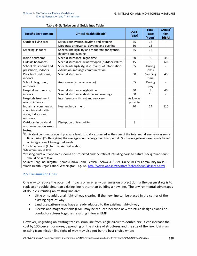
Volume I ‐ EIA Technical Review Guidelines: Energy Generation and Transmission
G. MITIGATION AND MONITORING MEASURES
CAFTA‐DR AND US COUNTRY EXPERTS SUPPORTED BY USAID‐ENVIRONMENT AND LABOR EXCELLENCE‐CCAD‐USEPA PROGRAM 188
Table G‐ 5: Noise Level Guidelines Table
Specific Environment Critical Health Effect(s) LAeq1 [dBA]
Time2 base
[hours]
LAmax3
fast [dBA]
Outdoor living area Serious annoyance, daytime and eveningModerate annoyance, daytime and evening
5550
16 16
‐‐
Dwelling, indoors Speech intelligibility and moderate annoyance, daytime and evening
35 16 ‐
Inside bedrooms Sleep disturbance, night‐time 30 8 45
Outside bedrooms Sleep disturbance, window open (outdoor values) 45 8 60
School classrooms and preschools, indoors
Speech intelligibility, disturbance of information extraction, message communication
35 During class
‐
Preschool bedrooms, indoors
Sleep disturbance 30 Sleeping time
45
School playground, outdoors
Annoyance (external source) 55 During play
‐
Hospital ward rooms, indoors
Sleep disturbance, night‐timeSleep disturbance, daytime and evenings
3030
8 16
40‐
Hospitals treatment rooms, indoors
Interference with rest and recovery As low as possible
Industrial, commercial, shopping and traffic areas, indoors and outdoors
Hearing impairment 70 24 110
Outdoors in parkland and conservation areas
Disruption of tranquility †
Notes: 1Equivalent continuous sound pressure level. Usually expressed as the sum of the total sound energy over some
time period (T), thus giving the average sound energy over that period. Such average levels are usually based on integration of A‐weighted levels.
2The time period (T) for the LAeq calculation. 3Maximum noise level. †Existing quiet outdoor areas should be preserved and the ratio of intruding noise to natural background sound
should be kept low. Source: Berglund, Birgitta, Thomas Lindvall, and Dietrich H Schwela. 1999. Guidelines for Community Noise. World Health Organization, Washington. pg. 65 http://www.who.int/docstore/peh/noise/guidelines2.html
2.5 Transmission Lines
One way to reduce the potential impacts of an energy transmission project during the design stage is to replace or double‐circuit an existing line rather than building a new line. The environmental advantages of double‐circuiting an existing line are:
Little or no additional right‐of‐way clearing, if the new line can be placed in the center of the existing right‐of‐way
Land use patterns may have already adapted to the existing right‐of‐way
Electric and magnetic fields (EMF) may be reduced because new structure designs place line conductors closer together resulting in lower EMF
However, upgrading an existing transmission line from single‐circuit to double‐circuit can increase the cost by 130 percent or more, depending on the choice of structures and the size of the line. Using an existing transmission line right‐of‐way may also not be the best choice when:
Volume I ‐ EIA Technical Review Guidelines: Energy Generation and Transmission
G. MITIGATION AND MONITORING MEASURES
CAFTA‐DR AND US COUNTRY EXPERTS SUPPORTED BY USAID‐ENVIRONMENT AND LABOR EXCELLENCE‐CCAD‐USEPA PROGRAM 189
The existing right‐of‐way is in a poor location
New residential areas have been built around the existing line
Electricity use has grown more in other areas, so using the existing right‐of‐way reduces the efficiency of the new line and increases costs
A wider right‐of‐way is needed because the size of the new line is much greater than the existing line
Another common method for mitigating impacts is corridor sharing. Transmission line right‐of‐ways can be shared with urban or rural roads, highways, railroads, or natural gas pipelines. Corridor sharing with existing facilities is usually encouraged because it minimizes impacts by:
Reducing the amount of new right‐of‐way required
Concentrating linear land uses and reducing the number of new corridors
Creating an incremental, rather than a new impact A common method to reduce EMF is to bring the lines closer together. This causes the fields created by each of the three conductors to interfere with each other and produce a reduced total magnetic field. Magnetic fields generated by double‐circuit lines are less than those generated by single‐circuit lines because the magnetic fields interact and produce a lower total magnetic field. In addition, double circuit poles are often taller resulting in less of a magnetic field at ground level. Underground transmission lines can be used as an environmental measure in areas where overhead lines create undesirable impacts. It is a common practice in residential areas to place low‐voltage distribution lines underground. However, placing high‐voltage transmission lines underground is less common and can cost two to ten times more than building an overhead line. While this practice may reduce aesthetic and other impacts, it may increase others. Underground transmission lines can be a reasonable alternative:
In urban areas where an overhead line can NOT be installed with appropriate clearances
When it allows for a shorter route than overhead
When aesthetic impacts would be significant Underground transmission lines can have the following disadvantages:
An increase in soil disturbance
A complete removal of small trees and brush along the transmission right‐of‐way
Increased construction and repair costs
Oil‐filled underground lines can leak, contaminating surrounding soils Underground cables should be well insulated to be safe and achieve meaningful power flow. This is achieved by encapsulating the aluminum or copper power line, with an insulator. This insulator can take several forms; from fluids (most common, i.e., insulating oil) to solids (non‐conducting dielectric polymer) to gas (sulfur hexafluoride ‐‐ SF6). Each has characteristic benefits and flaws. One of the most common insulating systems is High Pressure Fluid Filled (HPFF) underground transmission systems with system voltages of 69kV to 345kV, which have been in commercial operation for over 70 years. HPFF cable systems with rated system voltages up to and including 765kV are commercially available and have passed long‐term qualification tests.
Volume I ‐ EIA Technical Review Guidelines: Energy Generation and Transmission
G. MITIGATION AND MONITORING MEASURES
CAFTA‐DR AND US COUNTRY EXPERTS SUPPORTED BY USAID‐ENVIRONMENT AND LABOR EXCELLENCE‐CCAD‐USEPA PROGRAM 190
3 MONITORING AND OVERSIGHT
Monitoring plans for the affected resources are necessary to assure that methods used and results obtained can be used to assure that criteria established in the Environmental Measures plan are being met. The plan should address all phases of the power generation or transmission project: siting, construction, operation, closure and site reclamation. The scope of monitoring depends on the location, complexity of the operation and the severity of the potential impacts. Monitoring results can determine if:
Environmental measures are performing as required and results are as predicted, thus triggering release of financial assurance by the regulatory authority.
Environmental measures need to be adjusted to reach the criteria goals.
Enforcement is needed. As such, the monitoring plan should be designed to meet the following objectives:
To demonstrate compliance with the approved exploration, operations, and reclamation plan or plans and other national and local environmental laws and regulations.
To provide early detection of potential problems.
To supply information that can assist in directing corrective actions should they become necessary, including after the power plant or transmission line is decommissioned.
Where applicable, the monitoring should include:
Details on type and location of monitoring devices.
Sampling parameters and frequency.
Analytical methods and detection limits.
Quality assurance and quality control procedures.
Reporting procedures (to whom, how often, etc.).
Who will conduct and pay for monitoring.
Procedures to respond to adverse monitoring results. One of the values of a monitoring program is the early detection of potential problems. A good way to mitigate air or water quality impacts, for example, is to detect trends in samples and take early corrective action before violations of the performance standards occur. The monitoring plan should be tied to the environmental measures plan so that, if monitoring indicates problems (e.g., if air or water quality standards are violated or are about to be violated), specific corrective action procedures will be implemented by the owner/operator. It should not be left vague (e.g., “the company will work with the ministry to resolve the problem” is too vague). The plan should also include the standards and criteria that should be met. Examples of monitoring programs which may be necessary include:
Air quality
Surface and ground water quality and quantity
Revegetation success
Noise levels
Visual impacts
Wildlife mortality and other wildlife impacts
Volume I ‐ EIA Technical Review Guidelines: Energy Generation and Transmission
G. MITIGATION AND MONITORING MEASURES
CAFTA‐DR AND US COUNTRY EXPERTS SUPPORTED BY USAID‐ENVIRONMENT AND LABOR EXCELLENCE‐CCAD‐USEPA PROGRAM 191
Financial assurances may be required to ensure adequate funds will be available to implement the monitoring plan and mitigate detected problems if any, both during and after the generation and transmission projects. Some problems may not become evident for many years (e.g., groundwater contamination), so in some cases monitoring may need to be conducted for the duration of the project and even after closure. How long the funds are held can vary based on the type of operation and the modeling predictions.
4 FINANCIAL ASSURANCE
Financial assurance is usually required of mine operations because of the long term nature of post‐closure environmental measures and the economic uncertainties that can accompany mining given the markets for non‐metal and metal minerals. Their application to energy generation and transmission will depend upon the nature of the project and country practices. In such cases a financial guarantee may be required as a component of ongoing mitigation or monitoring measures and post‐closure process to cover the costs of closure or operation of critical equipment for monitoring and treatment should the project owner be unable to do so. Since these costs are the responsibility of the power plant owner, these costs are not included in the budgets of regulatory agencies, nor should they be. In addition, if monitoring, maintenance, and/or treatment activities will be required after power plant closure over a long‐term (decades or even in perpetuity), a long‐term trust fund should be established at the start of the project to ensure funds will be available as long as they are needed to conduct this work.
4.1 Financial Guarantees for Mitigation and Monitoring Measures and Restoration
Government agencies need financial sureties that are readily available to ensure that environmental measures and site restoration occur, if needed. Should the project owner default on environmental measures or restoration commitments, funds may be required immediately for an outside contractor to operate and maintain key facilities such as water treatment plants. Restoration and post‐closure activities conducted by an outside contractor cost more than activities conducted by the owner because the contractor or the government itself will have mobilization and other costs that the company did not have while it was operating the plant. Therefore, the cost estimate upon which the surety is based should be calculated to include the costs of a third party conducting the work. It should also be accurate and up to date. Unfortunately, errors in these calculations have required millions of dollars of taxpayer subsidy to close bankrupt operations. Governments have employed a number of financial vehicles to meet surety requirements. These vehicles generally take two forms: independently guaranteed sureties and sureties guaranteed by power generation companies. Because power companies can and do go bankrupt, NGOs and governments favor sureties that are independent of the company operating the project, usually in the form of a bond, irrevocable letter of credit, cash deposit or some combination of these instruments. Where a financial surety is guaranteed by the energy project operator through corporate guarantee, governments should assess the additional risks posed by relying on these instruments since they would be unavailable should the company go bankrupt. The financial sector has not developed specific requirements for sureties, although banks risk significant loss of capital if a company were to declare bankruptcy while still holding outstanding loans. Finally, considerable information is available on the calculation of the financial surety for any project. Because of problems encountered with financial sureties some academics and leading NGOs have urged for more government and public scrutiny, some of their recommendations are presented in Table G‐6.
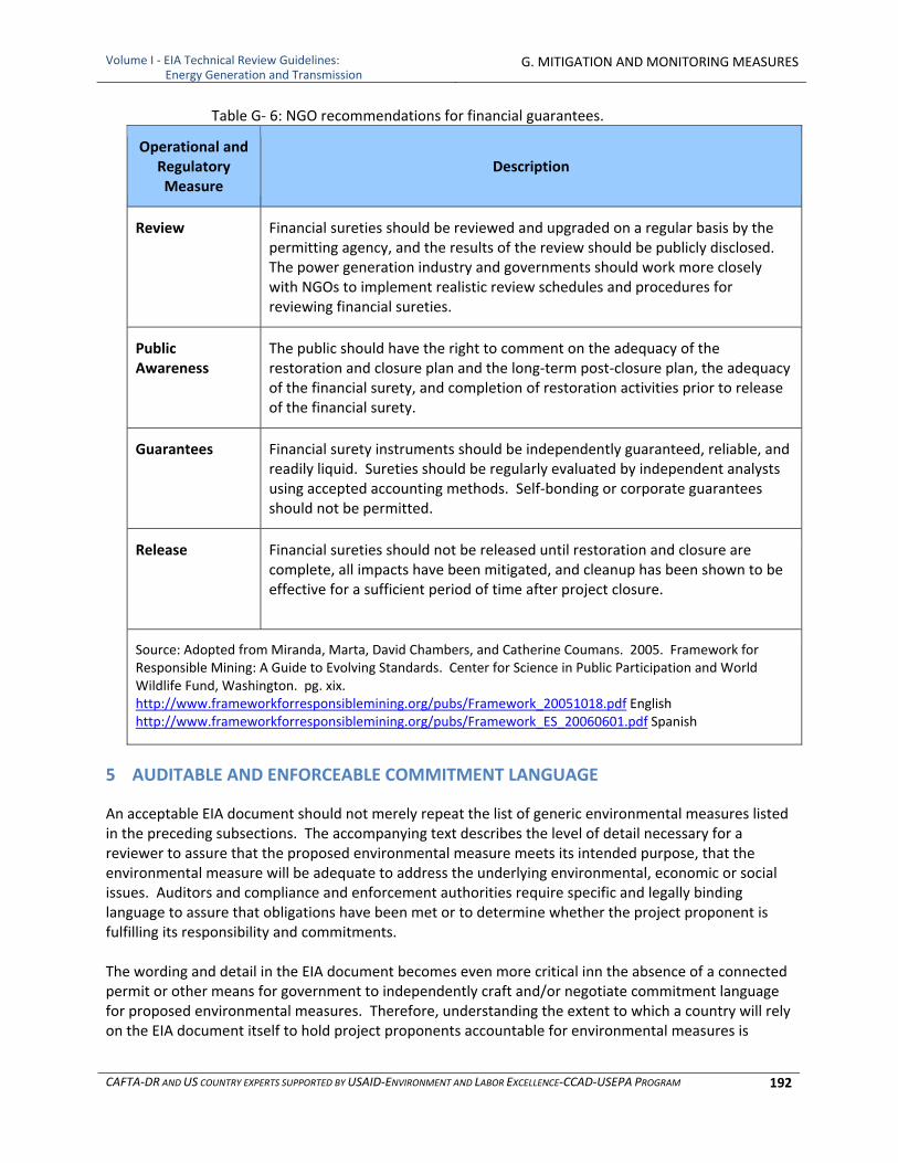
Volume I ‐ EIA Technical Review Guidelines: Energy Generation and Transmission
G. MITIGATION AND MONITORING MEASURES
CAFTA‐DR AND US COUNTRY EXPERTS SUPPORTED BY USAID‐ENVIRONMENT AND LABOR EXCELLENCE‐CCAD‐USEPA PROGRAM 192
Table G‐ 6: NGO recommendations for financial guarantees.
Operational and Regulatory Measure
Description
Review Financial sureties should be reviewed and upgraded on a regular basis by the permitting agency, and the results of the review should be publicly disclosed. The power generation industry and governments should work more closely with NGOs to implement realistic review schedules and procedures for reviewing financial sureties.
Public Awareness
The public should have the right to comment on the adequacy of the restoration and closure plan and the long‐term post‐closure plan, the adequacy of the financial surety, and completion of restoration activities prior to release of the financial surety.
Guarantees Financial surety instruments should be independently guaranteed, reliable, and readily liquid. Sureties should be regularly evaluated by independent analysts using accepted accounting methods. Self‐bonding or corporate guarantees should not be permitted.
Release Financial sureties should not be released until restoration and closure are complete, all impacts have been mitigated, and cleanup has been shown to be effective for a sufficient period of time after project closure.
Source: Adopted from Miranda, Marta, David Chambers, and Catherine Coumans. 2005. Framework for Responsible Mining: A Guide to Evolving Standards. Center for Science in Public Participation and World Wildlife Fund, Washington. pg. xix. http://www.frameworkforresponsiblemining.org/pubs/Framework_20051018.pdf English http://www.frameworkforresponsiblemining.org/pubs/Framework_ES_20060601.pdf Spanish
5 AUDITABLE AND ENFORCEABLE COMMITMENT LANGUAGE
An acceptable EIA document should not merely repeat the list of generic environmental measures listed in the preceding subsections. The accompanying text describes the level of detail necessary for a reviewer to assure that the proposed environmental measure meets its intended purpose, that the environmental measure will be adequate to address the underlying environmental, economic or social issues. Auditors and compliance and enforcement authorities require specific and legally binding language to assure that obligations have been met or to determine whether the project proponent is fulfilling its responsibility and commitments. The wording and detail in the EIA document becomes even more critical inn the absence of a connected permit or other means for government to independently craft and/or negotiate commitment language for proposed environmental measures. Therefore, understanding the extent to which a country will rely on the EIA document itself to hold project proponents accountable for environmental measures is
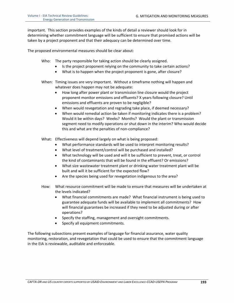
Volume I ‐ EIA Technical Review Guidelines: Energy Generation and Transmission
G. MITIGATION AND MONITORING MEASURES
CAFTA‐DR AND US COUNTRY EXPERTS SUPPORTED BY USAID‐ENVIRONMENT AND LABOR EXCELLENCE‐CCAD‐USEPA PROGRAM 193
important. This section provides examples of the kinds of detail a reviewer should look for in determining whether commitment language will be sufficient to ensure that promised actions will be taken by a project proponent and that their adequacy can be determined over time. The proposed environmental measures should be clear about:
Who: The party responsible for taking action should be clearly assigned.
Is the project proponent relying on the community to take certain actions?
What is to happen when the project proponent is gone, after closure?
When: Timing issues are very important. Without a timeframe nothing will happen and whatever does happen may not be adequate:
How long after power plant or transmission line closure would the project proponent monitor emissions and effluents? X years following closure? Until emissions and effluents are proven to be negligible?
When would revegetation and regrading take place, if deemed necessary?
When would remedial action be taken if monitoring indicates there is a problem? Would it be within days? Weeks? Months? Would the plant or transmission segment need to modify operations or shut down in the interim? Who would decide this and what are the penalties of non‐compliance?
What: Effectiveness will depend largely on what is being proposed:
What performance standards will be used to interpret monitoring results?
What level of treatment/control will be purchased and installed?
What technology will be used and will it be sufficient to prevent, treat, or control the kind of contaminants that will be found in the effluent? Or emissions?
What size wastewater treatment plant or drinking water treatment plant will be built and will it be sufficient for the expected flow?
Are the species being used for revegetation indigenous to the area?
How: What resource commitment will be made to ensure that measures will be undertaken at the levels indicated?
What financial commitments are made? What financial instrument is being used to guarantee adequate funds will be available to implement all commitments? How will financial guarantees be increased if they need to be adjusted during or after operations?
Specify the staffing, management and oversight commitments.
Specify all equipment commitments. The following subsections present examples of language for financial assurance, water quality monitoring, restoration, and revegetation that could be used to ensure that the commitment language in the EIA is reviewable, auditable and enforceable.
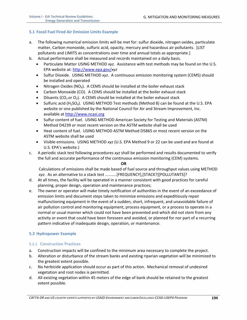
Volume I ‐ EIA Technical Review Guidelines: Energy Generation and Transmission
G. MITIGATION AND MONITORING MEASURES
CAFTA‐DR AND US COUNTRY EXPERTS SUPPORTED BY USAID‐ENVIRONMENT AND LABOR EXCELLENCE‐CCAD‐USEPA PROGRAM 194
5.1 Fossil Fuel Fired Air Emission Limits Example
a. The following numerical emission limits will be met for: sulfur dioxide, nitrogen oxides, particulate matter, Carbon monoxide, sulfuric acid, opacity, mercury and hazardous air pollutants. [LIST pollutants and LIMITS as concentrations over time and annual totals as appropriate.]
b. Actual performance shall be measured and records maintained on a daily basis.
Particulate Matter USING METHOD xyz. Assistance with test methods may be found on the U.S. EPA website at: http://www.epa.gov/xyz
Sulfur Dioxide. USING METHOD xyz. A continuous emission monitoring system (CEMS) should be installed and operated
Nitrogen Oxides (NOX). A CEMS should be installed at the boiler exhaust stack
Carbon Monoxide (CO). A CEMS should be installed at the boiler exhaust stack
Diluents (CO2 or O2). A CEMS should be installed at the boiler exhaust stack
Sulfuric acid (H2SO4). USING METHOD Test methods (Method 8) can be found at the U.S. EPA website or one published by the National Council for Air and Stream Improvement, Inc. available at http://www.ncasi.org
Sulfur content of fuel. USING METHOD American Society for Testing and Materials (ASTM) Method D4239 or most recent version on the ASTM website shall be used
Heat content of fuel. USING METHOD ASTM Method D5865 or most recent version on the ASTM website shall be used
Visible emissions. USING METHOD xyz (U.S. EPA Method 9 or 22 can be used and are found at U.S. EPA’s website.)
c. A periodic stack test following procedures xyz shall be performed and results documented to verify the full and accurate performance of the continuous emission monitoring (CEM) systems.
OR Calculations of emissions shall be made based of fuel source and throughput values using METHOD xyz. As an alternative to a stack test ………..[FREQUENCY],[STACK?][POLLUTANTS]?
d. At all times, the facility will be operated in a manner consistent with good practices for careful planning, proper design, operation and maintenance practices;
e. The owner or operator will make timely notification of authorities in the event of an exceedance of emission limits and document steps taken to minimize emissions and expeditiously repair malfunctioning equipment in the event of a sudden, short, infrequent, and unavoidable failure of air pollution control and monitoring equipment, process equipment, or a process to operate in a normal or usual manner which could not have been prevented and which did not stem from any activity or event that could have been foreseen and avoided, or planned for nor part of a recurring pattern indicative of inadequate design, operation, or maintenance.
5.2 Hydropower Example
5.2.1 Construction Practices
a. Construction impacts will be confined to the minimum area necessary to complete the project. b. Alteration or disturbance of the stream banks and existing riparian vegetation will be minimized to
the greatest extent possible. c. No herbicide application should occur as part of this action. Mechanical removal of undesired
vegetation and root nodes is permitted. d. All existing vegetation within 45 meters of the edge of bank should be retained to the greatest
extent possible.

Volume I ‐ EIA Technical Review Guidelines: Energy Generation and Transmission
G. MITIGATION AND MONITORING MEASURES
CAFTA‐DR AND US COUNTRY EXPERTS SUPPORTED BY USAID‐ENVIRONMENT AND LABOR EXCELLENCE‐CCAD‐USEPA PROGRAM 195
e. Temporary access roads. i. Steep slopes. Do not build temporary roads mid‐slope or on slopes steeper than 30 percent. ii. Temporary stream crossings.
f. Do not allow equipment in the flowing water portion of the stream channel where equipment activity could release sediment downstream, except at designated stream crossings.
g. Minimize the number of temporary stream crossings. h. Design new temporary stream crossings as follows:
i. Survey and map any potential spawning habitat within 90 meters downstream of a proposed crossing.
ii. Do not place stream crossings at known or suspected spawning areas or within 90 meters upstream of such areas if spawning areas may be affected.
iii. Design the crossing to provide for foreseeable risks (e.g., flooding and associated bedload and debris) to prevent the diversion of stream flow out of the channel and down the road if the crossing fails.
iv. Vehicles and machinery will cross riparian buffer areas and streams at right angles to the main channel wherever possible.
i. Obliteration. When the project is completed, obliterate all temporary access roads, stabilize the soil, and revegetate the site. Abandon and restore temporary roads in wet or flooded areas by the end of the in‐water work period.
j. Vehicles. When heavy equipment will be used, the equipment selected will have the least adverse effects on the environment (e.g., minimally sized, low ground pressure equipment).
k. Site preparation. Conserve native materials for site rehabilitation. i. If possible, leave native materials where they are found. ii. If materials are moved, damaged, or destroyed, replace them with a functional equivalent
during site rehabilitation. iii. Stockpile any large wood, native vegetation, weed‐free topsoil, and native channel material
displaced by construction for use during site rehabilitation. l. Isolation of in‐water work area. If adult or juvenile fish are reasonably certain to be present, or if
the work area is less than 300 ft upstream of spawning habitats, completely isolate the work area from the active flowing stream using inflatable bags, sandbags, sheet pilings, or similar materials.
m. Earthwork. Complete earthwork (including drilling, excavation, dredging, filling, and compacting) as quickly as possible.
n. Excavation. Material removed during excavation will only be placed in locations where it cannot enter sensitive aquatic resources. Whenever topsoil is removed, it should be stored and reused on site to the greatest extent possible. If culvert inlet/outlet protecting riprap is used, it will be class 350 metric or larger, and topsoil will be placed over the rock and planted with native woody vegetation.
o. Drilling and sampling. If drilling, boring, or jacking is used, the following conditions apply. i. Isolate drilling activities in wetted stream channels using a steel pile, sleeve, or other
appropriate isolation method to prevent drilling fluids from contacting water. ii. If it is necessary to drill through a bridge deck, use containment measures to prevent drilling
debris from entering the channel. iii. If directional drilling is used, the drill, bore, or jack hole will span the channel migration zone
and any associated wetland. iv. Sampling and directional drill recovery/recycling pits, and any associated waste or spoils, will
be completely isolated from surface waters, off‐channel habitats, and wetlands. All drilling fluids and waste will be recovered and recycled or disposed to prevent entry into flowing water.

Volume I ‐ EIA Technical Review Guidelines: Energy Generation and Transmission
G. MITIGATION AND MONITORING MEASURES
CAFTA‐DR AND US COUNTRY EXPERTS SUPPORTED BY USAID‐ENVIRONMENT AND LABOR EXCELLENCE‐CCAD‐USEPA PROGRAM 196
p. Site stabilization. Stabilize all disturbed areas, including obliteration of temporary roads, following any break in work, unless construction will resume within 4 days.
5.2.2 Flow Releases and Monitoring
5.2.2.1 Whitman Creek Minimum Instream Flow
a. A minimum instream flow shall be released from the base of Whitman Lake dam, into lower Whitman Creek, for the protection and enhancement of fish and wildlife resources, riparian vegetation, aesthetic resources, and water quality, pursuant to the following schedule, and as measured at the stream flow gage required below:
November 16 – April 30: 0.17 cubic meters per second (m3/s) May 1 – September 15: 0.23 m3/s September 16 – November 15: 0.31 m3/s
b. These minimum instream flows may be temporarily modified if required by operating emergencies beyond the control of the applicant, and for short periods upon agreement between the applicant and the [appropriate agencies]. If the flows are so modified, the applicant shall notify the [appropriate agencies] within 12 hours of any such incident.
5.2.2.2 Whitman Creek Bypass Channel Maintenance Flows
a. A channel maintenance flow (to reduce silt build‐up and maintain the physical characteristics of the stream channel) of 4.25 m3/s shall be released annually from the Whitman Lake dam into lower Whitman Creek, as measured at the lower Whitman Creek stream flow gage required below. This channel maintenance flow shall be released for a single day (24 continuous hours) each year between June 1 and August 15.
b. The minimum instream flows and channel maintenance flows may be temporarily modified if required by operating emergencies beyond the control of the applicant, or upon agreement between the applicant and [appropriate agencies]. If the flow is so modified, the applicant shall notify the [appropriate agencies] within 12 hours of any such incident.
5.2.2.3 Whitman Creek Stream Gage, Flow Monitoring, and Recording
a. A stream gage shall be installed on lower Whitman Creek downstream of the minimum instream flow release point, approximately 210 meters downstream from Whitman dam. The gage shall be constructed in a manner that will document minimum instream flow compliance in Whitman Creek. The applicant shall be responsible for the maintenance and operation of the gage. All data shall be recorded at a frequency of not greater than 15‐minute intervals and filed with the [appropriate entity] by April 1st of each year, documenting the previous water year. Copies of the data shall be provided upon request.
b. Before installing the Whitman Creek stream gage, the applicant shall consult with the [appropriate agencies] on the appropriate equipment, location, and timing of the installation. The applicant shall allow a minimum of 30 days for the agencies to comment and to make recommendations before installing the stream gage.
c. Upon completion of the installation, the applicant shall file a report with [appropriate agencies] detailing the installation of the stream gage. The applicant shall include with the report stage/discharge relationships for the gage; documentation of consultation, including copies of comments and recommendations on the appropriate equipment, location, and timing of the installations after consultation with the agencies; and specific descriptions of how the comments were accommodated. If the applicant does not adopt a recommendation, the report shall include the applicant’s reasons, based on project‐specific information.

Volume I ‐ EIA Technical Review Guidelines: Energy Generation and Transmission
G. MITIGATION AND MONITORING MEASURES
CAFTA‐DR AND US COUNTRY EXPERTS SUPPORTED BY USAID‐ENVIRONMENT AND LABOR EXCELLENCE‐CCAD‐USEPA PROGRAM 197
5.2.3 Endangered Species Management
To protect endangered bird species from disturbance, the project shall be constructed and maintained according to the following schedule:
5.2.3.1 Construction
a. January 1 through February 28‐‐Operation of heavy equipment is permitted between the hours of 10:00 AM to 4:00 PM. Lightweight passenger vehicles may enter the area and personnel may conduct activities deemed to be of low‐disturbance potential (e.g., install wiring, program computers, and interior finish work) between the hours of 8:00 AM and 5:00 PM.
b. March 1 through August 31‐‐Blasting/boring of dam is prohibited. Operation of heavy equipment is permitted only between the hours of 10:00 AM to 4:00 PM. Lightweight passenger vehicles may enter the area and personnel may conduct activities deemed to be of low‐disturbance potential (e.g., install wiring, program computers, and interior finish work) between the hours of 8:00 AM and 5:00 PM.
c. In‐stream work shall occur during the autumn to avoid temporary disturbance to the prey base during the nesting season.
5.2.3.2 Operation
a. With the exception of safety related emergencies, any maintenance or repairs requiring the use of blasting or boring equipment shall be scheduled from September 1 to February 28 to avoid the sensitive nesting season. Maintenance or repairs that require the use of heavy equipment from March 1 through August 31 shall be limited to the hours of 10:00 AM to 4:00 PM.
5.3 Transmission Line Example
5.3.1 Alignment/Right‐of‐Way Location
a. Transmission corridors shall be located to allow reconstruction (reconductoring or rebuilding) of existing transmission lines to the practical consistent with sound engineering and system reliability principles.
b. New transmission lines shall parallel existing transmission lines to the extent practical and to the extent that such actions do not violate sound engineering principles or system reliability criteria.
c. Transmission alignment and associated structures shall be placed to avoid sensitive features, such as such as riparian areas, water courses, cultural resource sites, and other sensitive resources.
d. The alignment of any new access roads shall be designed to minimize overall impacts, including ground disturbance and visual impacts. Access roads shall follow the contour of the land to extent practical rather than a straight line along the right‐of‐way where steep features could result in higher erosion potential.
e. Interconnections shall be made to existing substations to the extent practical to avoid impacts to new areas.
f. New access ways shall be located at least 30 meters, where practical, from rivers, ponds, lakes, and reservoirs.
g. Stream crossings shall be avoided to the extent practical. h. Narrow, flood prone areas shall be spanned.
5.3.2 Construction Practice
a. Applicant shall consult this permit authority regarding protocols for conducting pre‐construction surveys to identify biological, cultural, and other resources of concern. Surveys will then be

Volume I ‐ EIA Technical Review Guidelines: Energy Generation and Transmission
G. MITIGATION AND MONITORING MEASURES
CAFTA‐DR AND US COUNTRY EXPERTS SUPPORTED BY USAID‐ENVIRONMENT AND LABOR EXCELLENCE‐CCAD‐USEPA PROGRAM 198
conducted in consultation with this permit authority to establish buffer zones, construction time windows, animal relocation, and other appropriate measures.
b. Wherever possible, power poles, access roads and any other ground‐disturbing activities would be placed to avoid direct impacts to cultural resources. An independent professional archaeologist shall assist the pole‐siting crew in avoiding impacts to archaeological and historic sites. In cases where avoidance of sites is not feasible, a site specific Treatment Plan and Data Recovery Plan shall be developed in consultation with this permit authority and any affected tribes. Native groups, tribes, and communities shall be consulted to determine whether there are effective or practical ways of addressing impacts on traditional cultural properties and archaeological sites.
c. All construction vehicle movement shall be restricted to the right‐of‐way, designated access, contractor‐acquired access, or public roads. Widening or upgrading of existing access roads shall be limited to the minimum required as necessary to implement the selected alternative. New road construction shall be minimized as practicable.
d. Construction activities shall be limited to the pole construction areas, staging areas, laydown area, and access described in the EIA, with activity restricted to and confined within those limits. The applicant shall develop a system of colored identification flags or survey markers to identify restricted areas such as wildlife zones, archaeological sites, or right‐of‐way boundaries. The applicant shall arrange mandatory preconstruction seminars and training sessions to acquaint field personnel with these provisions. No paint or permanent discoloring agents would be applied to rocks or vegetation to indicate limits of survey or construction activity.
e. Prior to construction, all construction personnel and heavy equipment operators would be instructed on the protection of cultural, paleontological, and other sensitive resources.
f. During construction, if any cultural or paleontological resources are discovered, work shall immediately cease within a 50‐foot radius of the discovery. Any artifacts, remains, or fossils discovered shall not be disturbed and the applicant shall notify this permit authority of the discovery immediately.
g. In construction areas where recontouring is not required, vegetation shall be left in place wherever possible and original contour maintained to avoid excessive root damage and allow for resprouting
h. Construction equipment and vehicles that show excessive emissions of exhaust gases due to poor engine adjustments, or other inefficient operating conditions, would not be operated until repairs or adjustments are made.
i. Burning or burying waste materials on the right‐of‐way and plant construction areas shall not be permitted. All waste materials shall be disposed at permitted waste disposal areas or landfills. Tree and grubbing residue may be buried on the plant site or in the right‐of‐way with landowner approval.
j. In construction areas (e.g., construction yards, tower sites, spur roads from existing access roads) where ground disturbance is substantial or where recontouring is required, the applicant shall consult the land owner or this permit authority to determine specific restoration requirements. The methods of restoration normally would consist of returning disturbed areas to their natural contour or to blend with adjacent landforms, reseeding (if required), installing cross drains for erosion control, placing water bars in the road, or filling ditches. These instances shall be reviewed on a case‐by‐case basis in consultation with this permit authority and landowner, as appropriate, to limit access into the area and visual disturbance.
k. Equipment washing, the storage of petroleum products, lubricants, solvents and hazardous materials, structure sites, and other disturbed areas would be located at least 30 meters, where practical, from rivers, streams (including ephemeral streams), ponds, lakes, and reservoirs. This includes construction vehicles and heavy equipment when parked overnight or longer.

Volume I ‐ EIA Technical Review Guidelines: Energy Generation and Transmission
G. MITIGATION AND MONITORING MEASURES
CAFTA‐DR AND US COUNTRY EXPERTS SUPPORTED BY USAID‐ENVIRONMENT AND LABOR EXCELLENCE‐CCAD‐USEPA PROGRAM 199
l. If the banks of ephemeral stream crossings are sufficiently high and steep that breaking them down for a crossing would cause excessive disturbance, culverts would be installed using the same measures as for culverts on perennial streams.
m. Applicant shall employ practices to prevent introduction or spread of invasive species (e.g., by cleaning of construction equipment).
n. Clearing for access roads would be limited to only those trees necessary to permit the passage of equipment. All vegetative materials resulting from clearing operations would either be chipped on site or stacked in the right‐of‐way in accordance with the landowner’s request, as appropriate.
o. Native shrubs that would not interfere with access or the safe operation of the transmission line would be allowed to reestablish in the right‐of‐way.
p. The applicant shall develop an Avian Protection Plan (APP) to minimize impacts to nesting birds, as well as to minimize the electrocution and collision of migratory and resident bird species. The APP shall include provisions for adequate distance between conductors and distances between conductors and grounded surfaces. It shall identify time frames for construction and routine maintenance to avoid the nesting period of breeding birds. It would also include methods for minimizing bird collisions during line routing as well as methods for minimizing collisions following construction. The APP would follow guidelines described at <www.aplic.org>. The applicant, in coordination with this permit authority and after reviewing the final route alignments, shall determine where and what kind of line marking devices (i.e., visibility enhancing devices) need to be applied.
5.3.3 Landowner/ Resident Concerns
a. In addition to alignment/ right‐of‐way measures described above, the specific location of the right‐of‐way shall be aligned to the extent practical to avoid or reduce impacts on residents and inhabitants nearby.
b. Applicant shall meet and confer with landowners who are within or adjacent to the Route Corridor and other interested parties in order to develop a plan for specific pole locations that will mitigate the environmental and visual impact of the Project transmission lines within the Route Corridor. Applicant shall meet with each landowner together with representatives of this permit authority to discuss impacts to their particular property, including any issues that a particular landowner has before finalizing the alignment of the transmission line and the location of access roads. During such discussions, it is possible that this permit authority will propose locating the transmission line or access roads outside of the 0.25‐mi (0.40‐km) wide study corridor that is analyzed in this EIA.
c. Right‐of‐way shall be purchased through negotiations with each landowner affected by the proposed Project. Payment would be made of full value for crop damages or other property damage during construction or maintenance.
d. Fences and gates shall be repaired or replaced to their original condition prior to project disturbance as required by the landowner or this permit authority if they are damaged or destroyed by construction activities. Temporary gates would be installed only with the permission of the landowner or this permit authority.
e. Applicant shall respond to and resolve individual complaints of radio, television, and other electronic communication interference generated by the transmission line.
f. Applicant shall respond to and eliminate any problems of induced currents and voltages onto conducive objects sharing a right‐of‐way to the mutual satisfaction of the parties involved.
g. Watering facilities and other livestock range improvements shall be repaired or replaced if they are damaged by construction activities to their condition before disturbance.
h. Vegetation shall be replaced at landowner’s request. Care shall be used to preserve the natural landscape and vegetation. Construction operations shall be conducted to prevent, to the extent

Volume I ‐ EIA Technical Review Guidelines: Energy Generation and Transmission
G. MITIGATION AND MONITORING MEASURES
CAFTA‐DR AND US COUNTRY EXPERTS SUPPORTED BY USAID‐ENVIRONMENT AND LABOR EXCELLENCE‐CCAD‐USEPA PROGRAM 200
practical, any unnecessary destruction, scarring, or defacing of the natural surroundings, vegetation, trees, and native shrubbery in the vicinity of the work.
i. When weather and ground conditions permit, all deep ruts that are hazardous to farming operations and equipment movement shall be eliminated or compensation provided as an alternative if the landowner desires. Such ruts shall be leveled, filled, and graded, or otherwise eliminated in an approved manner. Ruts, scars, and compacted soils from construction activities in hay meadows, agricultural fields, pastures, and cultivated productive lands would be loosened and leveled by scarifying, harrowing, discing, or other appropriate method. Damage to ditches, tile drains, terraces, roads, and other land features would be corrected. Land contours and facilities would be restored as nearly as practical to their original conditions.
j. To avoid nuisance conditions due to construction noise, all internal combustion engines used in connection with construction activity would be fitted with an approved muffler and spark arrester.
k. Transmission lines shall be designed to minimize noise and other effects from energized conductors. Audible noise and electric and magnetic fields during construction and operation of the proposed Project shall be addressed as necessary on a case‐by case in consultation with affected landowners and this permit authority, as appropriate.
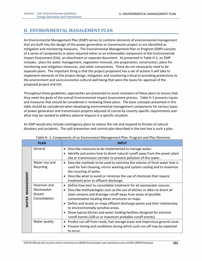
Volume I ‐ EIA Technical Review Guidelines: Energy Generation and Transmission
H. ENVIRONMENTAL MANAGEMENT PLAN
CAFTA‐DR AND US COUNTRY EXPERTS SUPPORTED BY USAID‐ENVIRONMENT AND LABOR EXCELLENCE‐CCAD‐USEPA PROGRAM 201
H. ENVIRONMENTAL MANAGEMENT PLAN
An Environmental Management Plan (EMP) serves to combine elements of environmental management that are built into the design of the power generation or transmission project or are identified as mitigation and monitoring measures. The Environmental Management Plan or Program (EMP) consists of a series of components or plans required either as an enforceable component of the Environmental Impact Assessment (EIA), an attachment or separate document. As presented in Table H‐1, an EMP includes: plans for water management, vegetation removal, site preparation, construction, plans for monitoring and mitigation measures, and other components. These do not necessarily need to be separate plans. The important thing is that the project proponent has a set of actions it will take to implement elements of the project design, mitigation and monitoring critical to providing protections to the environment and socio‐economic‐cultural well being that were the bases for approval of the proposed project and EIA. Throughout these guidelines, approaches are presented to assist reviewers of these plans to ensure that they meet the goals of the overall Environmental Impact Assessment process. Table H‐1 presents inputs and measures that should be considered in reviewing these plans. The basic concepts presented in this table should be considered when developing environmental management components for various types of power generation and transmission projects adjusted of course by country specific requirements and what may be needed to address adverse impacts in a specific situation. An EMP would also include contingency plans to reduce the risk and respond to threats of natural disasters and accidents. The spill prevention and control plan described in the text box is such a plan.
Table H‐ 1: Components of an Environment Management Plan: Program and Plan Elements
PLAN INPUT
WATER M
ANAGEM
ENT
General Describe measures to be implemented to manage water.
Identify and assess how to divert natural runoff away from the power plant site or transmission corridor to prevent pollution of this water.
Water Use and Recycling
Describe methods to be used to minimize the volume of fresh water that is used for fuel cleaning, mirror washing and system cooling and to maximize the recycling of water.
Describe what to avoid or minimize the use of chemicals that require treatment prior to effluent discharge.
Diversion and Wastewater Stream Consolidation
Define how best to consolidate treatment for all wastewater sources.
Describe methodologies such as the use of ditches or dikes to divert all clean streams and drainage runoff away from areas of possible contamination locating these structures on maps.
Define and locate on maps effluent discharge points and their relationship to environmentally sensitive areas.
Show typical ditches and water holding facilities designed for extreme runoff events (100‐yr or maximum probable runoff events).
Water quality Predict run‐off from roads, fuel storage areas and impervious ground cover.
Present timing and conditions during which such run‐off may be expected to occur.
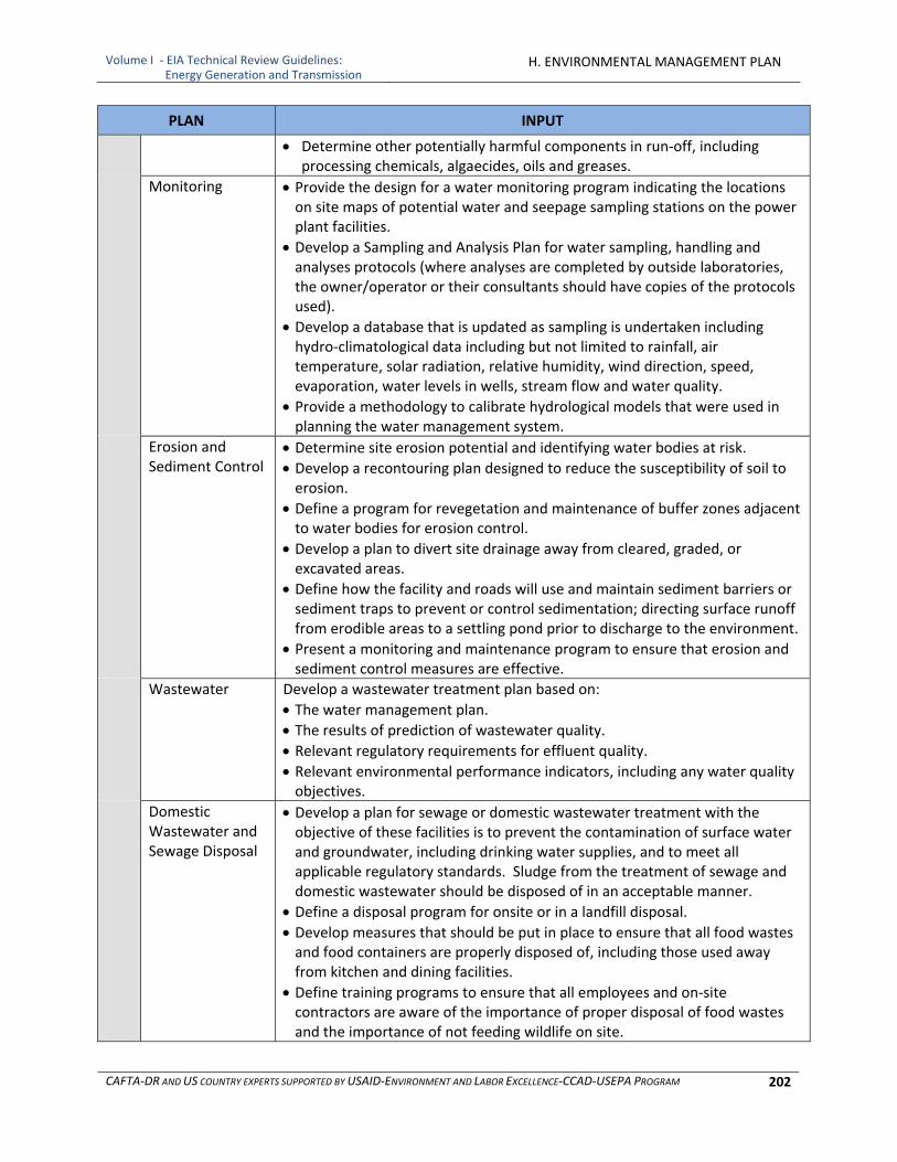
Volume I ‐ EIA Technical Review Guidelines: Energy Generation and Transmission
H. ENVIRONMENTAL MANAGEMENT PLAN
CAFTA‐DR AND US COUNTRY EXPERTS SUPPORTED BY USAID‐ENVIRONMENT AND LABOR EXCELLENCE‐CCAD‐USEPA PROGRAM 202
PLAN INPUT
Determine other potentially harmful components in run‐off, including processing chemicals, algaecides, oils and greases.
Monitoring Provide the design for a water monitoring program indicating the locations on site maps of potential water and seepage sampling stations on the power plant facilities.
Develop a Sampling and Analysis Plan for water sampling, handling and analyses protocols (where analyses are completed by outside laboratories, the owner/operator or their consultants should have copies of the protocols used).
Develop a database that is updated as sampling is undertaken including hydro‐climatological data including but not limited to rainfall, air temperature, solar radiation, relative humidity, wind direction, speed, evaporation, water levels in wells, stream flow and water quality.
Provide a methodology to calibrate hydrological models that were used in planning the water management system.
Erosion and Sediment Control
Determine site erosion potential and identifying water bodies at risk.
Develop a recontouring plan designed to reduce the susceptibility of soil to erosion.
Define a program for revegetation and maintenance of buffer zones adjacent to water bodies for erosion control.
Develop a plan to divert site drainage away from cleared, graded, or excavated areas.
Define how the facility and roads will use and maintain sediment barriers or sediment traps to prevent or control sedimentation; directing surface runoff from erodible areas to a settling pond prior to discharge to the environment.
Present a monitoring and maintenance program to ensure that erosion and sediment control measures are effective.
Wastewater Develop a wastewater treatment plan based on:
The water management plan.
The results of prediction of wastewater quality. Relevant regulatory requirements for effluent quality.
Relevant environmental performance indicators, including any water quality objectives.
Domestic Wastewater and Sewage Disposal
Develop a plan for sewage or domestic wastewater treatment with the objective of these facilities is to prevent the contamination of surface water and groundwater, including drinking water supplies, and to meet all applicable regulatory standards. Sludge from the treatment of sewage and domestic wastewater should be disposed of in an acceptable manner.
Define a disposal program for onsite or in a landfill disposal.
Develop measures that should be put in place to ensure that all food wastes and food containers are properly disposed of, including those used away from kitchen and dining facilities.
Define training programs to ensure that all employees and on‐site contractors are aware of the importance of proper disposal of food wastes and the importance of not feeding wildlife on site.
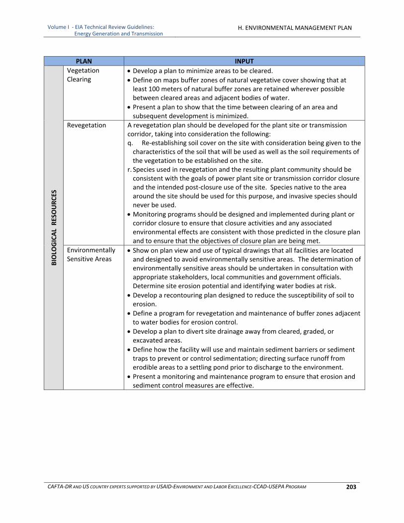
Volume I ‐ EIA Technical Review Guidelines: Energy Generation and Transmission
H. ENVIRONMENTAL MANAGEMENT PLAN
CAFTA‐DR AND US COUNTRY EXPERTS SUPPORTED BY USAID‐ENVIRONMENT AND LABOR EXCELLENCE‐CCAD‐USEPA PROGRAM 203
PLAN INPUT BIOLO
GICAL RESOURCES
Vegetation Clearing
Develop a plan to minimize areas to be cleared.
Define on maps buffer zones of natural vegetative cover showing that at least 100 meters of natural buffer zones are retained wherever possible between cleared areas and adjacent bodies of water.
Present a plan to show that the time between clearing of an area and subsequent development is minimized.
Revegetation A revegetation plan should be developed for the plant site or transmission corridor, taking into consideration the following: q. Re‐establishing soil cover on the site with consideration being given to the characteristics of the soil that will be used as well as the soil requirements of the vegetation to be established on the site.
r. Species used in revegetation and the resulting plant community should be consistent with the goals of power plant site or transmission corridor closure and the intended post‐closure use of the site. Species native to the area around the site should be used for this purpose, and invasive species should never be used.
Monitoring programs should be designed and implemented during plant or corridor closure to ensure that closure activities and any associated environmental effects are consistent with those predicted in the closure plan and to ensure that the objectives of closure plan are being met.
Environmentally Sensitive Areas
Show on plan view and use of typical drawings that all facilities are located and designed to avoid environmentally sensitive areas. The determination of environmentally sensitive areas should be undertaken in consultation with appropriate stakeholders, local communities and government officials. Determine site erosion potential and identifying water bodies at risk.
Develop a recontouring plan designed to reduce the susceptibility of soil to erosion.
Define a program for revegetation and maintenance of buffer zones adjacent to water bodies for erosion control.
Develop a plan to divert site drainage away from cleared, graded, or excavated areas.
Define how the facility will use and maintain sediment barriers or sediment traps to prevent or control sedimentation; directing surface runoff from erodible areas to a settling pond prior to discharge to the environment.
Present a monitoring and maintenance program to ensure that erosion and sediment control measures are effective.
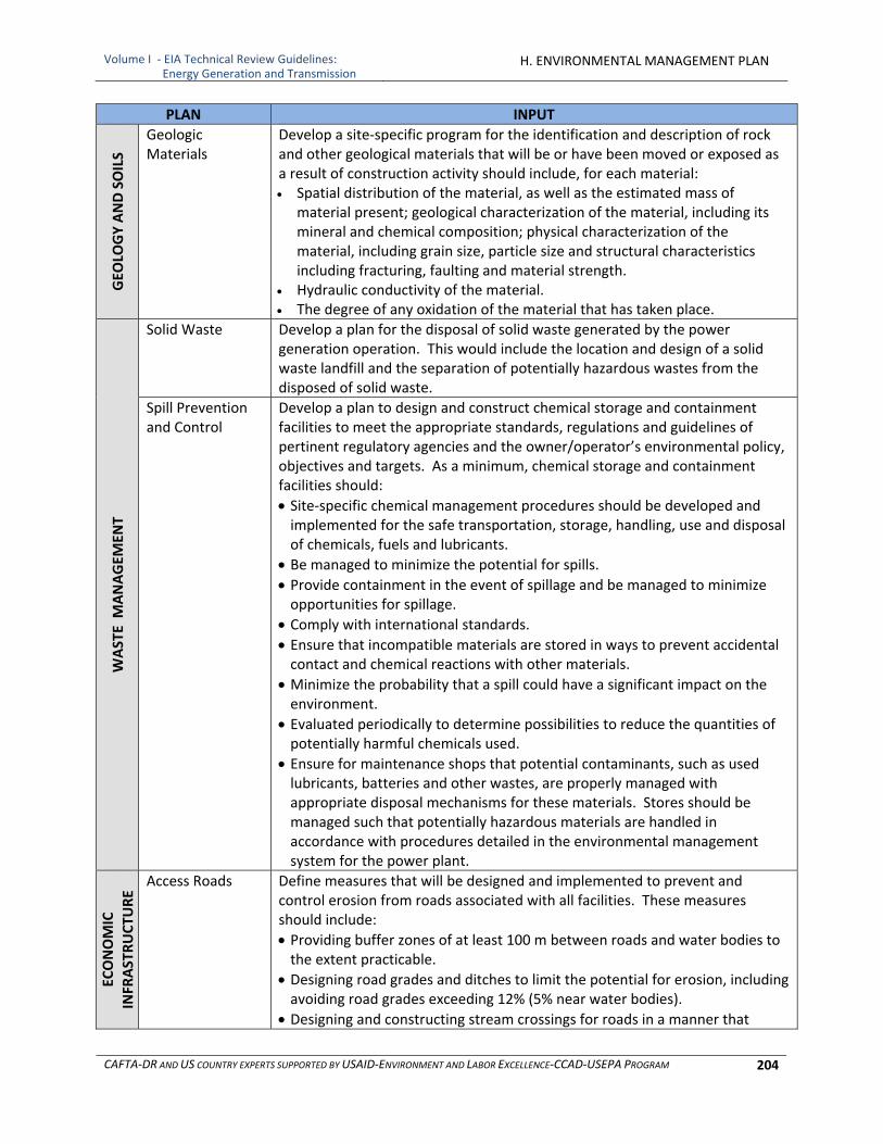
Volume I ‐ EIA Technical Review Guidelines: Energy Generation and Transmission
H. ENVIRONMENTAL MANAGEMENT PLAN
CAFTA‐DR AND US COUNTRY EXPERTS SUPPORTED BY USAID‐ENVIRONMENT AND LABOR EXCELLENCE‐CCAD‐USEPA PROGRAM 204
PLAN INPUT GEO
LOGY AND SOILS
Geologic Materials
Develop a site‐specific program for the identification and description of rock and other geological materials that will be or have been moved or exposed as a result of construction activity should include, for each material: Spatial distribution of the material, as well as the estimated mass of
material present; geological characterization of the material, including its mineral and chemical composition; physical characterization of the material, including grain size, particle size and structural characteristics including fracturing, faulting and material strength.
Hydraulic conductivity of the material. The degree of any oxidation of the material that has taken place.
WASTE M
ANAGEM
ENT
Solid Waste Develop a plan for the disposal of solid waste generated by the power generation operation. This would include the location and design of a solid waste landfill and the separation of potentially hazardous wastes from the disposed of solid waste.
Spill Prevention and Control
Develop a plan to design and construct chemical storage and containment facilities to meet the appropriate standards, regulations and guidelines of pertinent regulatory agencies and the owner/operator’s environmental policy, objectives and targets. As a minimum, chemical storage and containment facilities should:
Site‐specific chemical management procedures should be developed and implemented for the safe transportation, storage, handling, use and disposal of chemicals, fuels and lubricants.
Be managed to minimize the potential for spills.
Provide containment in the event of spillage and be managed to minimize opportunities for spillage.
Comply with international standards.
Ensure that incompatible materials are stored in ways to prevent accidental contact and chemical reactions with other materials.
Minimize the probability that a spill could have a significant impact on the environment.
Evaluated periodically to determine possibilities to reduce the quantities of potentially harmful chemicals used.
Ensure for maintenance shops that potential contaminants, such as used lubricants, batteries and other wastes, are properly managed with appropriate disposal mechanisms for these materials. Stores should be managed such that potentially hazardous materials are handled in accordance with procedures detailed in the environmental management system for the power plant.
ECONOMIC
INFR
ASTRUCTU
RE
Access Roads Define measures that will be designed and implemented to prevent and control erosion from roads associated with all facilities. These measures should include:
Providing buffer zones of at least 100 m between roads and water bodies to the extent practicable.
Designing road grades and ditches to limit the potential for erosion, including avoiding road grades exceeding 12% (5% near water bodies).
Designing and constructing stream crossings for roads in a manner that
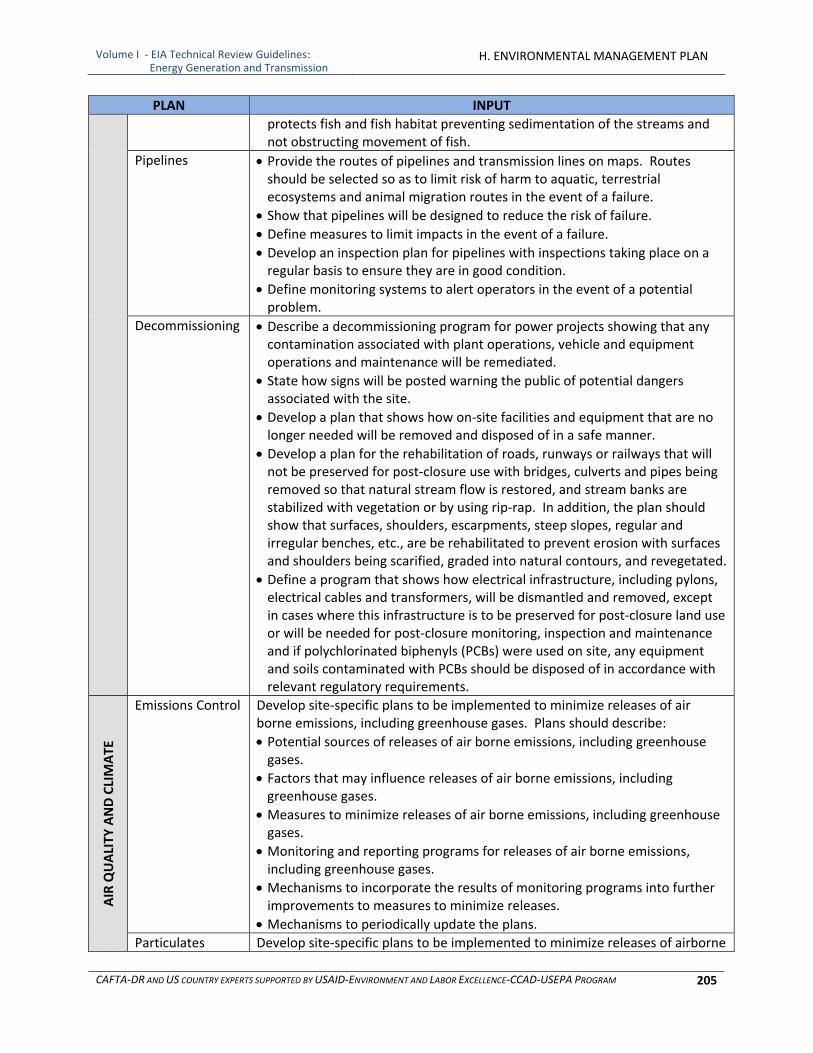
Volume I ‐ EIA Technical Review Guidelines: Energy Generation and Transmission
H. ENVIRONMENTAL MANAGEMENT PLAN
CAFTA‐DR AND US COUNTRY EXPERTS SUPPORTED BY USAID‐ENVIRONMENT AND LABOR EXCELLENCE‐CCAD‐USEPA PROGRAM 205
PLAN INPUT
protects fish and fish habitat preventing sedimentation of the streams and not obstructing movement of fish.
Pipelines Provide the routes of pipelines and transmission lines on maps. Routes should be selected so as to limit risk of harm to aquatic, terrestrial ecosystems and animal migration routes in the event of a failure.
Show that pipelines will be designed to reduce the risk of failure. Define measures to limit impacts in the event of a failure.
Develop an inspection plan for pipelines with inspections taking place on a regular basis to ensure they are in good condition.
Define monitoring systems to alert operators in the event of a potential problem.
Decommissioning Describe a decommissioning program for power projects showing that any contamination associated with plant operations, vehicle and equipment operations and maintenance will be remediated.
State how signs will be posted warning the public of potential dangers associated with the site.
Develop a plan that shows how on‐site facilities and equipment that are no longer needed will be removed and disposed of in a safe manner.
Develop a plan for the rehabilitation of roads, runways or railways that will not be preserved for post‐closure use with bridges, culverts and pipes being removed so that natural stream flow is restored, and stream banks are stabilized with vegetation or by using rip‐rap. In addition, the plan should show that surfaces, shoulders, escarpments, steep slopes, regular and irregular benches, etc., are be rehabilitated to prevent erosion with surfaces and shoulders being scarified, graded into natural contours, and revegetated.
Define a program that shows how electrical infrastructure, including pylons, electrical cables and transformers, will be dismantled and removed, except in cases where this infrastructure is to be preserved for post‐closure land use or will be needed for post‐closure monitoring, inspection and maintenance and if polychlorinated biphenyls (PCBs) were used on site, any equipment and soils contaminated with PCBs should be disposed of in accordance with relevant regulatory requirements.
AIR QUALITY
AND CLIMATE
Emissions Control Develop site‐specific plans to be implemented to minimize releases of air borne emissions, including greenhouse gases. Plans should describe:
Potential sources of releases of air borne emissions, including greenhouse gases.
Factors that may influence releases of air borne emissions, including greenhouse gases.
Measures to minimize releases of air borne emissions, including greenhouse gases.
Monitoring and reporting programs for releases of air borne emissions, including greenhouse gases.
Mechanisms to incorporate the results of monitoring programs into further improvements to measures to minimize releases.
Mechanisms to periodically update the plans.
Particulates Develop site‐specific plans to be implemented to minimize releases of airborne
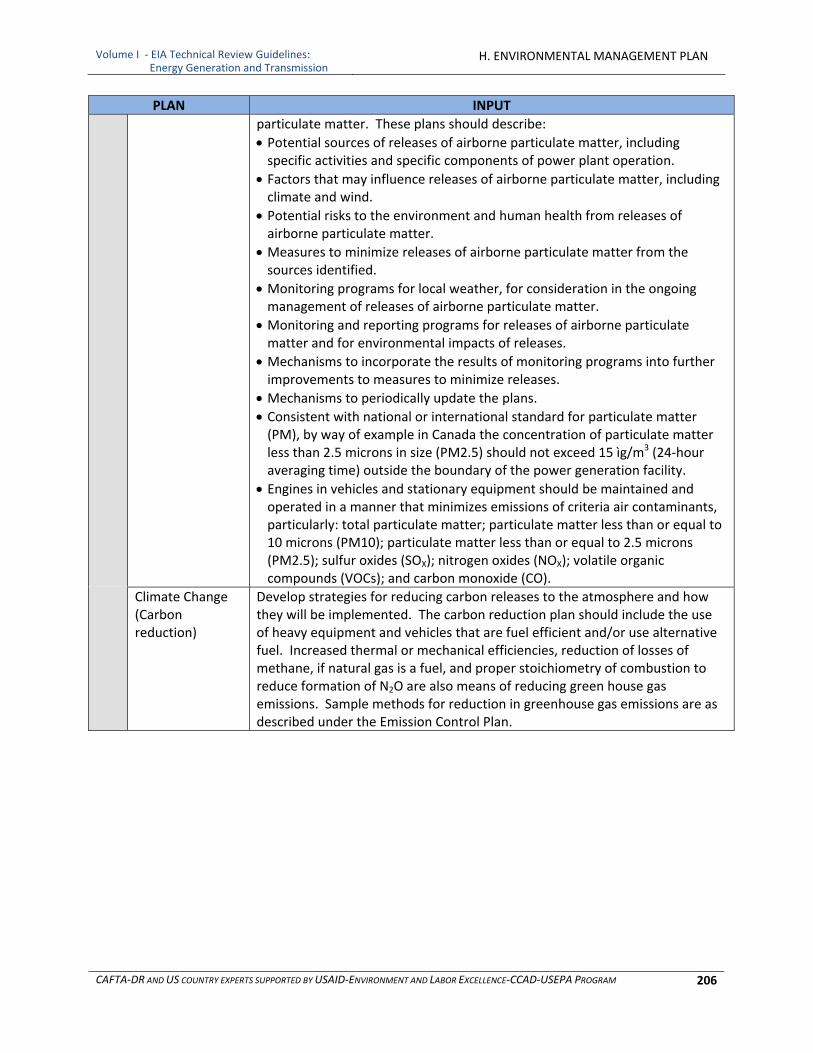
Volume I ‐ EIA Technical Review Guidelines: Energy Generation and Transmission
H. ENVIRONMENTAL MANAGEMENT PLAN
CAFTA‐DR AND US COUNTRY EXPERTS SUPPORTED BY USAID‐ENVIRONMENT AND LABOR EXCELLENCE‐CCAD‐USEPA PROGRAM 206
PLAN INPUT
particulate matter. These plans should describe:
Potential sources of releases of airborne particulate matter, including specific activities and specific components of power plant operation.
Factors that may influence releases of airborne particulate matter, including climate and wind.
Potential risks to the environment and human health from releases of airborne particulate matter.
Measures to minimize releases of airborne particulate matter from the sources identified.
Monitoring programs for local weather, for consideration in the ongoing management of releases of airborne particulate matter.
Monitoring and reporting programs for releases of airborne particulate matter and for environmental impacts of releases.
Mechanisms to incorporate the results of monitoring programs into further improvements to measures to minimize releases.
Mechanisms to periodically update the plans.
Consistent with national or international standard for particulate matter (PM), by way of example in Canada the concentration of particulate matter less than 2.5 microns in size (PM2.5) should not exceed 15 ìg/m3 (24‐hour averaging time) outside the boundary of the power generation facility.
Engines in vehicles and stationary equipment should be maintained and operated in a manner that minimizes emissions of criteria air contaminants, particularly: total particulate matter; particulate matter less than or equal to 10 microns (PM10); particulate matter less than or equal to 2.5 microns (PM2.5); sulfur oxides (SOX); nitrogen oxides (NOX); volatile organic compounds (VOCs); and carbon monoxide (CO).
Climate Change (Carbon reduction)
Develop strategies for reducing carbon releases to the atmosphere and how they will be implemented. The carbon reduction plan should include the use of heavy equipment and vehicles that are fuel efficient and/or use alternative fuel. Increased thermal or mechanical efficiencies, reduction of losses of methane, if natural gas is a fuel, and proper stoichiometry of combustion to reduce formation of N2O are also means of reducing green house gas emissions. Sample methods for reduction in greenhouse gas emissions are as described under the Emission Control Plan.
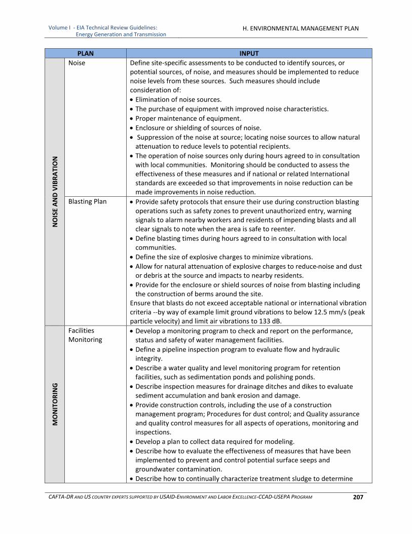
Volume I ‐ EIA Technical Review Guidelines: Energy Generation and Transmission
H. ENVIRONMENTAL MANAGEMENT PLAN
CAFTA‐DR AND US COUNTRY EXPERTS SUPPORTED BY USAID‐ENVIRONMENT AND LABOR EXCELLENCE‐CCAD‐USEPA PROGRAM 207
PLAN INPUT NOISE AND VIBRATION
Noise Define site‐specific assessments to be conducted to identify sources, or potential sources, of noise, and measures should be implemented to reduce noise levels from these sources. Such measures should include consideration of:
Elimination of noise sources.
The purchase of equipment with improved noise characteristics.
Proper maintenance of equipment.
Enclosure or shielding of sources of noise. Suppression of the noise at source; locating noise sources to allow natural attenuation to reduce levels to potential recipients.
The operation of noise sources only during hours agreed to in consultation with local communities. Monitoring should be conducted to assess the effectiveness of these measures and if national or related International standards are exceeded so that improvements in noise reduction can be made improvements in noise reduction.
Blasting Plan Provide safety protocols that ensure their use during construction blasting operations such as safety zones to prevent unauthorized entry, warning signals to alarm nearby workers and residents of impending blasts and all clear signals to note when the area is safe to reenter.
Define blasting times during hours agreed to in consultation with local communities.
Define the size of explosive charges to minimize vibrations.
Allow for natural attenuation of explosive charges to reduce noise and dust or debris at the source and impacts to nearby residents.
Provide for the enclosure or shield sources of noise from blasting including the construction of berms around the site.
Ensure that blasts do not exceed acceptable national or international vibration criteria ‐‐by way of example limit ground vibrations to below 12.5 mm/s (peak particle velocity) and limit air vibrations to 133 dB.
MONITORING
Facilities Monitoring
Develop a monitoring program to check and report on the performance, status and safety of water management facilities.
Define a pipeline inspection program to evaluate flow and hydraulic integrity.
Describe a water quality and level monitoring program for retention facilities, such as sedimentation ponds and polishing ponds.
Describe inspection measures for drainage ditches and dikes to evaluate sediment accumulation and bank erosion and damage.
Provide construction controls, including the use of a construction management program; Procedures for dust control; and Quality assurance and quality control measures for all aspects of operations, monitoring and inspections.
Develop a plan to collect data required for modeling.
Describe how to evaluate the effectiveness of measures that have been implemented to prevent and control potential surface seeps and groundwater contamination.
Describe how to continually characterize treatment sludge to determine
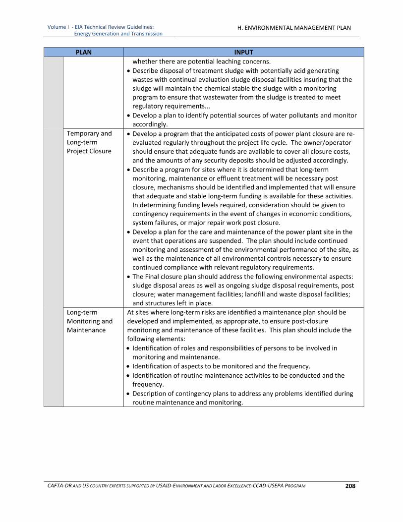
Volume I ‐ EIA Technical Review Guidelines: Energy Generation and Transmission
H. ENVIRONMENTAL MANAGEMENT PLAN
CAFTA‐DR AND US COUNTRY EXPERTS SUPPORTED BY USAID‐ENVIRONMENT AND LABOR EXCELLENCE‐CCAD‐USEPA PROGRAM 208
PLAN INPUT
whether there are potential leaching concerns.
Describe disposal of treatment sludge with potentially acid generating wastes with continual evaluation sludge disposal facilities insuring that the sludge will maintain the chemical stable the sludge with a monitoring program to ensure that wastewater from the sludge is treated to meet regulatory requirements...
Develop a plan to identify potential sources of water pollutants and monitor accordingly.
Temporary and Long‐term Project Closure
Develop a program that the anticipated costs of power plant closure are re‐evaluated regularly throughout the project life cycle. The owner/operator should ensure that adequate funds are available to cover all closure costs, and the amounts of any security deposits should be adjusted accordingly.
Describe a program for sites where it is determined that long‐term monitoring, maintenance or effluent treatment will be necessary post closure, mechanisms should be identified and implemented that will ensure that adequate and stable long‐term funding is available for these activities. In determining funding levels required, consideration should be given to contingency requirements in the event of changes in economic conditions, system failures, or major repair work post closure.
Develop a plan for the care and maintenance of the power plant site in the event that operations are suspended. The plan should include continued monitoring and assessment of the environmental performance of the site, as well as the maintenance of all environmental controls necessary to ensure continued compliance with relevant regulatory requirements.
The Final closure plan should address the following environmental aspects: sludge disposal areas as well as ongoing sludge disposal requirements, post closure; water management facilities; landfill and waste disposal facilities; and structures left in place.
Long‐term Monitoring and Maintenance
At sites where long‐term risks are identified a maintenance plan should be developed and implemented, as appropriate, to ensure post‐closure monitoring and maintenance of these facilities. This plan should include the following elements:
Identification of roles and responsibilities of persons to be involved in monitoring and maintenance.
Identification of aspects to be monitored and the frequency.
Identification of routine maintenance activities to be conducted and the frequency.
Description of contingency plans to address any problems identified during routine maintenance and monitoring.
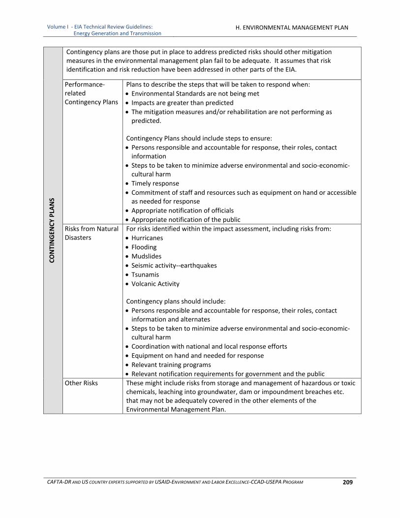
Volume I ‐ EIA Technical Review Guidelines: Energy Generation and Transmission
H. ENVIRONMENTAL MANAGEMENT PLAN
CAFTA‐DR AND US COUNTRY EXPERTS SUPPORTED BY USAID‐ENVIRONMENT AND LABOR EXCELLENCE‐CCAD‐USEPA PROGRAM 209
CONTINGEN
CY PLA
NS
Contingency plans are those put in place to address predicted risks should other mitigation measures in the environmental management plan fail to be adequate. It assumes that risk identification and risk reduction have been addressed in other parts of the EIA.
Performance‐related Contingency Plans
Plans to describe the steps that will be taken to respond when:
Environmental Standards are not being met
Impacts are greater than predicted
The mitigation measures and/or rehabilitation are not performing as predicted.
Contingency Plans should include steps to ensure:
Persons responsible and accountable for response, their roles, contact information
Steps to be taken to minimize adverse environmental and socio‐economic‐cultural harm
Timely response
Commitment of staff and resources such as equipment on hand or accessible as needed for response
Appropriate notification of officials Appropriate notification of the public
Risks from Natural Disasters
For risks identified within the impact assessment, including risks from:
Hurricanes Flooding Mudslides
Seismic activity‐‐earthquakes
Tsunamis
Volcanic Activity
Contingency plans should include:
Persons responsible and accountable for response, their roles, contact information and alternates
Steps to be taken to minimize adverse environmental and socio‐economic‐cultural harm
Coordination with national and local response efforts Equipment on hand and needed for response
Relevant training programs
Relevant notification requirements for government and the public
Other Risks These might include risks from storage and management of hazardous or toxic chemicals, leaching into groundwater, dam or impoundment breaches etc. that may not be adequately covered in the other elements of the Environmental Management Plan.

Volume I ‐ EIA Technical Review Guidelines: Energy Generation and Transmission
H. ENVIRONMENTAL MANAGEMENT PLAN
CAFTA‐DR AND US COUNTRY EXPERTS SUPPORTED BY USAID‐ENVIRONMENT AND LABOR EXCELLENCE‐CCAD‐USEPA PROGRAM 210
[This page was intentionally left blank.]

Volume I, Part 2 ‐ EIA Technical Review Guidelines:Energy Generation and Transmission
I.REFERENCES AND GLOSSARY
CAFTA‐DR AND US COUNTRY EXPERTS SUPPORTED BY USAID‐ENVIRONMENT AND LABOR EXCELLENCE‐CCAD‐USEPA PROGRAM 211
I. REFERENCES AND GLOSSARY
1 CITED REFERENCES
Arnett, Edward B., Manuela M. P. Huso, Micheal R. Schirmacher, and John P Hayes. 2011. “Altering turbine speed reduces bat mortality at wind‐energy facilities.” Frontiers in Ecology and Environment, 9(4): 209‐214.
Ash, Neville, Hernán Blanco, Claire Brown, Keisha Garcia, Thomas Henrichs, Nicolas Lucas, Ciara
Raudsepp‐Hearne, R. David Simpson, Robert Scholes, Thomas P. Tomich, Bhaskar Vira and Monika Zurek. 2010. Ecosystems and Human Well‐Being: a Manual for Assessment Practitioners. Island Press, Washington. 264 pp. http://www.unep‐wcmc.org/eap/pdf/EcosystemsHumanWellbeing.pdf
Barfield, B.J., Warner, R.C., and Haan, C.T., 1981. Applied Hydrology and Sedimentology for Disturbed Lands, Oklahoma Technical Press, Stillwater, OK, 603 pp.
Berglund, Birgitta, Thomas Lindvall, and Dietrich H Schwela. 1999. Guidelines for Community Noise. World Health Organization, Washington. 159 pp. http://www.who.int/docstore/peh/noise/guidelines2.html
Clark, C. O. 1945. Storage and the Unit Hydrograph. Amer. Soc. Civ. Engr. 110: 1419–1446.
Convention on International Trade in Endangered Species of Wild Fauna and Flora (CITES). undated. CITES Appendices. http://www.cites.org/eng/app/index.shtml
Council on Environmental Quality (CEQ). 1997. Considering Cumulative Effects under the NEPA Policy Act, January 1997. http://nepa.energy.gov/nepa_documents/TOOLS/GUIDANCE/Volume1/4‐11.1‐ceq‐cumulative‐effects.pdf
Hanna T.M., Azrag E.A., Atkinson L.C. (1994). Use of an analytical solution for preliminary estimates of groundwater inflow to a pit. Mining Engineering 46(2), 149‐152.
Hanson, Craig, John Finisdore, Janet Ranganathan and Charles Iceland. 2008. The Corporate Ecosystem Services Review: Guidelines for Identifying Business Risks & Opportunities Arising from Ecosystem Change. World Resources, Institute Meridian Institute and World Business Council for Sustainable Development. Washington. 37 pp.
International Association for Impact Assessment (IAIA). 1999. Principles of Environmental Impact Assessment Best Practice. 4 pp.
International Association for Public Participation (IAP2). 2006. IAP2's Public Participation Toolbox (Caja de Herramientas). International Association for Public Participation. Thorton, Colorado. 15(Eng) 9(Sp) pp. http://iap2.affiniscape.com/associations/4748/files/06Dec_Toolbox.pdf English http://www.iap2.org/associations/4748/files/toolboxsp.pdf Spanish
International Dark‐Sky Association and Illuminating Engineering Society of North America. 2010. Model Outdoor Lighting Ordinance (MLO) with USERS GUIDE. Second Public Review Draft, Board of Directors Version, June 3, 2010. 40 pp. http://docs.darksky.org/MLO/2010/MLOdraft19July.pdf

Volume I, Part 2 ‐ EIA Technical Review Guidelines:Energy Generation and Transmission
I.REFERENCES AND GLOSSARY
CAFTA‐DR AND US COUNTRY EXPERTS SUPPORTED BY USAID‐ENVIRONMENT AND LABOR EXCELLENCE‐CCAD‐USEPA PROGRAM 212
International Energy Agency (IEA). 2010. Technology Roadmap: Concentrating Solar Power. IEA, Paris. 45pp. http://www.iea.org/papers/2010/csp_roadmap.pdf
IEA. 2010. World Energy Outlook 2010, The Electricity Access Database. http://www.worldenergyoutlook.org/database_electricity/electricity_access_database.htm
IEA, country searches, graphics and tables http://www.iea.org/country/index_nmc.asp
IEA Bioenergy. 2009. Bioenergy a Sustainable and Reliable Energy: A Review of Status and Prospects. International Energy Agency, Paris. 108 pp. http://www.ieabioenergy.com/LibItem.aspx?id=6479
International Finance Corporation (IFC). 2007. Environmental, Health, and Safety (EHS) Guidelines: General EHS Guidelines. 99 pp. (Guías sobre medio ambiente, salud y seguridad: Guías Generales. 116 pp.) IFC, World Bank Group. http://www.ifc.org/ifcext/sustainability.nsf/AttachmentsByTitle/gui_EHSGuidelines2007_GeneralEHS/$FILE/Final+‐+General+EHS+Guidelines.pdf English http://www.ifc.org/ifcext/sustainability.nsf/AttachmentsByTitle/gui_EHSGuidelines2007_GeneralEHS_Spanish/$FILE/General+EHS+‐+Spanish+‐+Final+rev+cc.pdf Spanish
International Union for Conservation of Nature (IUCN). undated. Red List of the (http://www.iucnredlist.org) and the species in the appendices of the Jacob, C.E. and S.W. Lowman. 1952. Non‐steady Flow to a Well of Constant Drawdown in an Extensive Aquifer. Tran. Amer. Geophys. Union. V. 33, p. 559‐569.
Joyce Susan A. and Magnus MacFarlane. 2001. Social Impact Assessment in the Mining Industry: Current Situation and Future Directions. Background Document: Mining Minerals and Sustainable Development Project International Institute for Environment and Development, London, UK. 33 pp. http://www.oncommonground.ca/publications/SIA.htm English http://www.oncommonground.ca/publications/SIA_span.htm Spanish
Leopold, L.B., E. Clarke, B.B. Hanshaw, and J.B. Balsley. 1971. A Procedure for Evaluating Environmental Impact. United States Geological Survey Circular 645, United States Geological Survey, Washington, D.C., USA. 13 pp.
Linsley, R.K., Kohler, M.A., & Paulhus, J.L.H. (1975) Hydrology for Engineers, 2nd edition, 243‐245. McGraw‐Hill, New York.
Miranda, Marta, David Chambers, and Catherine Coumans. 2005. Framework for Responsible Mining: A
Guide to Evolving Standards. October 19, 2005, Center for Science in Public Participation and World Wildlife Fund, Washington. http://www.frameworkforresponsiblemining.org/pubs/Framework_20051018.pdf English http://www.frameworkforresponsiblemining.org/pubs/Framework_ES_20060601.pdf Spanish
Snyder, F. F. 1938. Synthetic Unit Graphs. Trans. Am. Geophys. Union. 19(1): 447–454.
Soil Conservation Service. 1972. National Engineering Handbook, Section 4, Hydrology. Washington, D.C.: USDA–SCS.
Volume I, Part 2 ‐ EIA Technical Review Guidelines:Energy Generation and Transmission
I.REFERENCES AND GLOSSARY
CAFTA‐DR AND US COUNTRY EXPERTS SUPPORTED BY USAID‐ENVIRONMENT AND LABOR EXCELLENCE‐CCAD‐USEPA PROGRAM 213
Turner, D.B. (1994). Workbook of atmospheric dispersion estimates: an introduction to dispersion modeling (2nd Edition ed.). CRC Press.).
United Nations Educational, Scientific and Cultural Organization (UNESCO). undated. World Heritage List (http://whc.unesco.org/en/list
United States Department of Energy (U.S. DOE) and Electric Power Research Institute (EPRI). 1997. Renewable Energy Technology Characterizations. Topical Report TR‐109496, December 1997. Electric Power Research Institute, Inc. and Office of Utility Technologies, Energy Efficiency and Renewable Energy, U.S. Department of Energy, Washington. 283 pp. http://www1.eere.energy.gov/ba/pba/pdfs/entire_document.pdf
United States Environmental Protection Agency (U.S. EPA). 1999. Consideration of Cumulative Impacts in EPA Review of NEPA Documents EPA 315‐R‐99‐002/May 1999.
United States Natural Resources Conservation Service’s procedures for “Estimation of Direct Runoff from Storm Rainfall” is the most common technique for estimating the volume of runoff after a storm event (National Engineering Handbook, Part 630, Chapter 10 http://directives.sc.egov.usda.gov/OpenNonWebContent.aspx?content=17752.wba
Van Zyl, D., Hutchison, I., and Kiel, J., 1988. Introduction to Evaluation, Design, and Operation of Precious Metal Heap Leaching Projects, Society of Mining Engineers, Inc., Littleton, CO.
Water Pollution Control Federation. 1969. Design and Construction of Sanitary and Storm Sewers, Manual of Practice 9, American Society of Civil Engineers Manual of Engineering Practice No. 37, Washington, DC. 283 pp.
World Bank. undated. Renewable Energy Toolkit Technology Module, page 3. http://siteresources.worldbank.org/INTRENENERGYTK/Resources/REToolkit_Technologies.pdf
World Health Organization (WHO). 2003. Guidelines for Safe Recreational Water Environments: Volume 1, Coastal and Fresh Waters. Guidelines for recreational use are an example of health based guideline values for receiving waters based on intended use. WHO, Geneva. 219 pp. http://www.who.int/water_sanitation_health/bathing/srwg1.pdf
2 OTHER REFERENCES
2.1 General
Anderson, James R., Ernest E. Hardy, John T. Roach, Richard E.A Whitmer. 1976. Land Use And Land Cover Classification System For Use With Remote Sensor Data. Geological Survey Professional Paper 964, A revision of the land use classification system as presented in U.S. Geological Survey Circular 671. http://landcover.usgs.gov/pdf/anderson.pdf
Babcock Wilcox “Steam, Its Generation and Use”, 41st Edition, 2005
Baerwald, E.F., G.H. D’Amours, B.J. Klug, and R. M. Barclay. 2008. “Barotrauma is a significant cause of bat fatalities at wind turbines. “Current Biology, 18(16): R695‐R696.
Volume I, Part 2 ‐ EIA Technical Review Guidelines:Energy Generation and Transmission
I.REFERENCES AND GLOSSARY
CAFTA‐DR AND US COUNTRY EXPERTS SUPPORTED BY USAID‐ENVIRONMENT AND LABOR EXCELLENCE‐CCAD‐USEPA PROGRAM 214
Baerwald et al. “A Large‐Scale Mitigation Experiment to Reduce Bat Fatalities at Wind Energy Facilities.” Journal of Wildlife Management, 2009; 73(7): 1077.
Baerwald, Erin; and Barclay, Robert. 2009. Geographic Variation in Activity and Fatality of Migratory Bats
at Wind Energy Facilities. Journal of Mammalogy 90, 1341‐1349.
Boyd, James. undated. Financial Responsibility for Environmental Obligations: An Analysis of Environmental Bonding and Assurance Rules.
Bureau Land Management (BLM). undated. Wind Energy Development Programmatic EIS Website. BLM, United States Department of Interior (U.S. DOI). http://windeis.anl.gov/
BLM Geothermal Resources Leasing Programmatic EISWebsite. undated. BLM, U.S. DOI. http://www.blm.gov/wo/st/en/prog/energy/geothermal/geothermal_nationwide.html
California Energy Commission. 2007. California Guidelines for Reducing Impacts to Birds and Bats from Wind Energy Development. Commission Final Report. California Energy Commission, Renewables Committee, and Energy Facilities Siting Division, and California Department of Fish and Game, Resources Management and Policy Division. CEC‐700‐2007‐
California Energy Commission. 2009. Best Management Practices & Guidance Manual: Desert
Renewable Energy Projects. Draft Staff Report, CEC‐700‐2009‐016‐SD, October 5, 2009. 91 pp. http://www.energy.ca.gov/2009publications/CEC‐700‐2009‐016/CEC‐700‐2009‐016‐SD.PDF
Council on Environmental Quality (CEQ). 2007. Aligning National Environmental Policy Act Processes with Environmental Management Systems ‐ A Guide for NEPA and EMS Practitioners. April 2007.
CEQ. 2007. Collaboration in NEPA – A Handbook for NEPA Practitioners. October, 2007.
CEQ. 2007. A Citizen’s Guide to the NEPA Having your Voice Heard. December, 2007.
CEQ. undated. Regulations for Implementing NEPA http://ceq.hss.doe.gov/nepa/regs/ceq/toc_ceq.htm
Cryan, Paul M., and M.R. Barclay. 2009. “Causes of Bat Fatalities at Wind Turbines: Hypotheses and Predications,” Journal of Mammology, 90(6): 1330‐1340.
DHI. 2008. Linking Water, Energy & Climate Change: A proposed water and energy policy initiative for
the UN Climate Change Conference, COP15, in Copenhagen 2009. Draft Concept Note, January 2008. http://www.semide.net/media_server/files/Y/l/water‐energy‐climatechange_nexus.pdf
Federal Energy Regulatory Commission (FERC). 2008. Preparing Environmental Documents ‐ Guidelines for Applicants, Contractors, and Staff. Office of Energy Projects, Division of Hydropower Licensing, FERC, September 2008. 119 pp. http://www.ferc.gov/industries/hydropower/gen‐info/guidelines/eaguide.pdf
Harrelson, C.C., C.L. Rawlins, and J.P. Potyondy. 1994. Stream Channel Reference Sites: An Illustrated Guide to Field Technique. U.S. Department of Agriculture, U.S. Forest Service, Fort Collins, CO.
Volume I, Part 2 ‐ EIA Technical Review Guidelines:Energy Generation and Transmission
I.REFERENCES AND GLOSSARY
CAFTA‐DR AND US COUNTRY EXPERTS SUPPORTED BY USAID‐ENVIRONMENT AND LABOR EXCELLENCE‐CCAD‐USEPA PROGRAM 215
International Finance Corporation (IFC). 2007. Guidance Note 1, Social and Environmental Assessment and Management Systems, July 31, 2007. http://www.ifc.org/ifcext/sustainability.nsf/AttachmentsByTitle/pol_GuidanceNote2007_1/$FILE/2007+Updated+Guidance+Note_1.pdfHill, J. .1996. Environmental Considerations in Licensing Hydropower Projects: Policies and Practices at the Federal Energy Regulatory Commission. American Fisheries Society Symposium 16:190‐199.
IFC. 2007. Environmental, Health, and Safety (EHS) Guidelines: Wind Energy. 17 pp. (Guías sobre medio ambiente, salud y seguridad: Energía Eólica. 21 pp.) IFC, World Bank Group. http://www.ifc.org/ifcext/sustainability.nsf/AttachmentsByTitle/gui_EHSGuidelines2007_WindEnergy/$FILE/Final+‐+Wind+Energy.pdf English http://www.ifc.org/ifcext/sustainability.nsf/AttachmentsByTitle/gui_EHSGuidelines2007_WindEnergy_Spanish/$FILE/0000199659ESes+Wind+Energy+rev+cc.pdf Spanish
IFC. 2007. Environmental, Health, and Safety (EHS) Guidelines: Geothermal Power Generation. 13 pp. (Guías sobre medio ambiente, salud y seguridad: Generación de Energía Geotérmica. 15 pp.) IFC, World Bank Group. http://www.ifc.org/ifcext/sustainability.nsf/AttachmentsByTitle/gui_EHSGuidelines2007_GeothermalPowerGen/$FILE/Final+‐+Geothermal+Power+Generation.pdf English http://www.ifc.org/ifcext/sustainability.nsf/AttachmentsByTitle/gui_EHSGuidelines2007_GeothermalPowerGen_Spanish/$FILE/0000199659ESes+Geothermal+Power+Generation.pdf Spanish
IFC. 2007. Environmental, Health, and Safety (EHS) Guidelines: Electric Power Transmission and Distribution 23 pp. (Guías sobre medio ambiente, salud y seguridad: Transmisión y Distribución de Electricidad. 26 pp.) IFC, World Bank Group. http://www.ifc.org/ifcext/sustainability.nsf/AttachmentsByTitle/gui_EHSGuidelines2007_ElectricTransmission/$FILE/Final+‐+Electric+Transmission+and+Distribution.pdf English http://www.ifc.org/ifcext/sustainability.nsf/AttachmentsByTitle/gui_EHSGuidelines2007_ElectricTransmission_Spanish/$FILE/0000199659ESes+Electric+Power+Transmission+and+Distribution+rev+cc.pdf Spanish
IFC. 2008. Environmental, Health, and Safety (EHS) Guidelines: Thermal Power Plants. 33pp. (Guías sobre medio ambiente, salud y seguridad: Plantas de Energía Térmica. 41pp.) IFC, World Bank Group. http://www.ifc.org/ifcext/sustainability.nsf/AttachmentsByTitle/gui_EHSGuidelines2007_ThermalPower/$FILE/FINAL_Thermal+Power.pdf English http://www.ifc.org/ifcext/sustainability.nsf/AttachmentsByTitle/gui_EHSGuidelines2007_ThermalPower_Spanish/$FILE/0000360593ESes.pdf Spanish
Interorganizational Committee for Guidelines and Principles for SIA (ICGP). 1994. Guidelines and Principles for Social Impact Assessment. U.S. Department Commerce. Reprinted in Burdge, 1998.
Kagel, Alyssa. 2008. The State of Geothermal, Part II Subsurface Technology. Geothermal Energy Association for U.S. DOE, January 2008 http://www.geo‐energy.org/reports/Geothermal%20Technology%20‐%20Part%20II%20(Surface).pdf
Kruczynski, W.L. 1990,Options to be considered in preparation and evaluation of mitigation plans. In: Wetland Creation and Restoration: the Status of the Science, J.A. Kusler and M.E. Kenrula (eds.), Island Press, Washington, D.C. pp. 555‐569.
Volume I, Part 2 ‐ EIA Technical Review Guidelines:Energy Generation and Transmission
I.REFERENCES AND GLOSSARY
CAFTA‐DR AND US COUNTRY EXPERTS SUPPORTED BY USAID‐ENVIRONMENT AND LABOR EXCELLENCE‐CCAD‐USEPA PROGRAM 216
Mandelker, D.R. 1992. NEPA Law and Litigation. Second edition. Clark Boardman Callaghan, New York.
Martin, Jeremy. 2010. Central America Energy Integration and the SIEPAC Project: From a Fragmented Market to a New Reality. paper delivered at the Center for Hemispheric Energy Cooperation, University of Miami and Security Hemispheric Task Force, May 2010 https://www6.miami.edu/hemispheric‐policy/Martin_Central_America_Electric_Int.pdf
National Renewable Energy Laboratory (NREL). undated. Technology Website ‐‐ biomass, geothermal, solar, wind and photovoltaic. NREL, U.S. DOE http://www.nrel.gov/science_technology/
Office of Energy Efficiency and Renewable Energy (OEERE). undated. Solar Energy Development Program EIS Information Center Website. Joint project of the OEERE, U.S. Department of Energy (U.S. DOE); and the Bureau of Land Management, U.S. Department of the Interior. http://solareis.anl.gov/index.cfm
Petts, Judith, ed. 1999. Handbook of Environmental Impact Assessment – Vol II. Wiley‐Blackwell pub., 960 p.
Platts, W.S., W.F. Megahan, and G.W. Minshall. 1983. Methods for Evaluating Stream, Riparian, and Biotic Conditions. General Technical Report INT‐138, U.S. Department of Agriculture, U.S. Forest Service, Ogden, UT.
Public Service Commission of Wisconsin. 2010. Environmental Impacts of Transmission Lines. http://psc.wi.gov/thelibrary/publications/electric/electric10.pdf
Ramsar Convention on Wetlands. undated. Ramsar Sites Information Service Website. http://ramsar.wetlands.org/
Soil Conservation Service. 1975. Procedure for Computing Sheet and Rill Erosion on Project, Area, Technical Release No. 5 1. Soil Conservation Service, United States Department of Agriculture.
Taylor, Mark A. 2007. The State of Geothermal, Part I Subsurface Technology. Geothermal Energy Association for United States Department of Energy (U.S. DOE), November 2007 http://www.geo‐energy.org/reports/Geothermal%20Technology%20Part%20I%20‐%20Subsurface%20Technology%20(Nov%202007).pdf
University of Calgary. "Scientists Find Successful Way To Reduce Bat Deaths At Wind Turbines." ScienceDaily, September 28, 2009.
Union of Concerned Scientists. 2009. Environmental Impacts of Renewable Energy Technologies.
United Nations Environment Progamme (UNEP). 1995. Environmental Impact Assessment Training Resource Manual.
United States Code of Federal Regulations (CFR). 2008. Forest Service Procedures for Implementing NEPA Procedures. 36 CFR Part 200.6, Forest Service Handbook 1909.15.
Volume I, Part 2 ‐ EIA Technical Review Guidelines:Energy Generation and Transmission
I.REFERENCES AND GLOSSARY
CAFTA‐DR AND US COUNTRY EXPERTS SUPPORTED BY USAID‐ENVIRONMENT AND LABOR EXCELLENCE‐CCAD‐USEPA PROGRAM 217
United States Department of the Army, Corps of Engineers. 1987. Corps of Engineers Wetlands Delineation Manual, Final Technical Report Y‐87‐l, U.S. Army Corps of Engineers, Environmental Laboratory, Waterways Experiment Station, Vicksburg, MS.
United States Department of Energy (U.S. DOE). 2004. Recommendations for the Preparation of Environmental Assessments and Environmental Impact Statements, Second Edition. Office of NEPA Policy and Compliance, Environmental Safety and Health, U.S. DOE. http://www.gc.doe.gov/NEPA/documents/green_book2004_12_30_final.pdf
U.S. DOE. 1997. Environmental Impact Statement Checklist. Office of NEPA Policy and Compliance, Environmental Safety and Health, U.S. DOE. http://nepa.energy.gov/documents/eischk2.pdf
U.S. DOE. 1994. Environmental Assessment Checklist. Office of NEPA Policy and Compliance, Environmental Safety and Health, U.S. DOE. http://nepa.energy.gov/documents/iv‐7.pdf
United States Department of the Interior (U.S. DOI). 2006. Technology White Papers on Energy Potential on the U.S. Outer Continental Shelf, one each for Wind, Wave, Ocean Current, and Solar. Minerals Management Service, Renewable Energy and Alternate Use Program, U.S. DOI, May 2006 http://ocsenergy.anl.gov/documents/index.cfm
United States Environmental Protection Agency (U.S. EPA). 1999. Office of Federal Activities, Considering Ecological Processes in Environmental Impact Assessments, July 1999.
U.S. EPA. 1993. Habitat Evaluation: Guidance for the Review of Environmental Impact Assessment Documents, Washington, DC.
U.S. EPA. 1989. Rapid Bioassessment Protocols for Use in Streams and Rivers: Benthic Macroinvertebrates and Fish, EPA/440/4‐89/001, Washington, DC.
U.S. EPA. 1986. Quality Criteria for Water, REPA 440/5‐86‐001. Washington, DC.
U.S. EPA. 1984. Overview of Solid Waste Generation, Management, and Chemical Characteristics, Prepared for U.S. EPA under Contract Nos. 68‐03‐3197, PN 3617‐3 by PEI Associates, Inc.
U.S. EPA. undated. National Environmental Policy Act (NEPA), Basic Information. Environmental and Health Sciences Group, EPA Contract 68‐W4‐0030, Work Assignment 7.
United States Fish and Wildlife Service (USFWS). 2011. Draft Land‐Based Wind Energy Guidelines: Recommendations on measures to avoid, minimize, and compensate for effects to fish, wildlife, and their habitats. USFWS, U.S. DOI http://www.fws.gov/windenergy/docs/Wind_Energy_Guidelines_2_15_2011FINAL.pdf
The Wildlife Society. 1980. Wildlife Management Techniques Manual, Fourth Edition: Revised. Sanford D. Schemnitz (editor), Washington, D.C.
World Bank. 1999. The World Bank Operations Manual P 4.01, Annex B ‐ Content of an Environmental Assessment Report for a Category A Project, January, 1999. http://web.worldbank.org/WBSITE/EXTERNAL/PROJECTS/EXTPOLICIES/EXTOPMANUAL/0,,contentMDK:20065951~menuPK:64701637~pagePK:64709096~piPK:64709108~theSitePK:502184,00.html
Volume I, Part 2 ‐ EIA Technical Review Guidelines:Energy Generation and Transmission
I.REFERENCES AND GLOSSARY
CAFTA‐DR AND US COUNTRY EXPERTS SUPPORTED BY USAID‐ENVIRONMENT AND LABOR EXCELLENCE‐CCAD‐USEPA PROGRAM 218
2.2 CAFTA‐DR Sector and EIA References
2.2.1 Regional
Comisión Centroamericana de Ambiente y Desarrollo (CCAD) website: http://www.ccad.ws/ IUCN EIA in Central America website: http://www.eia‐centroamerica.org/
2.2.2 Costa Rica
SETENA website: http://www.minae.go.cr/dependencias/desconcentradas/secretaria_tecnica_nacional_ambiental.html
2.2.3 Dominican Republic
MMARN website: http://www.ambiente.gob.do/
2.2.4 El Salvador
MARN website: http://www.marn.gob.sv/index.php
2.2.5 Guatemala
MARN website: http://www.marn.gob.gt/
2.2.6 Honduras
SERNA website: http://www.serna.gob.hn/
2.2.7 Nicaragua
MARENA website: http://www.marena.gob.ni/ Diagnostico sobre potenciales y restricciones biofísicas, sociales, institucionales y económicas para el desarrollo de los biocombustibles en Nicaragua, Ministerio de Energía y Minas, 2010. Informe de la Capacitación sobre la Revisión de Estudios de Impacto Ambienta en el Sector de Energía Eléctrica, Marzo 2004.
2.3 United States Sector, EIA and Permitting Internet Resources
2.3.1 United States Environmental Protection Agency:
Regulatory Information for the Energy Sector English: www.epa.gov/lawsregs/bizsector/energy.html Power Generator Compliance Assistance English: www.epa.gov/compliance/assistance/sectors/power.html Profile of the Fossil Fuel Electric Power Generation Industry English: www.epa.gov/compliance/resources/publications/assistance/sectors/notebooks.html Non‐Hydroelectric Renewable Energy English: www.epa.gov/cleanenergy/energy‐and‐you/affect/non‐hydro.html Hydroelectricity
Volume I, Part 2 ‐ EIA Technical Review Guidelines:Energy Generation and Transmission
I.REFERENCES AND GLOSSARY
CAFTA‐DR AND US COUNTRY EXPERTS SUPPORTED BY USAID‐ENVIRONMENT AND LABOR EXCELLENCE‐CCAD‐USEPA PROGRAM 219
English: www.epa.gov/cleanenergy/energy‐and‐you/affect/hydro.html
2.3.2 United States Department of Energy
2.3.2.1 Links to Example Environmental Impact Statements
Electrical transmission lines (http://www.gc.doe.gov/NEPA/finalEIS‐0365.htm and http://www.gc.doe.gov/NEPA/finalEIS‐0336.htm and many others);
Hydropower fish mitigation (http://www.gc.doe.gov/NEPA/documents/EIS‐0397FEIS.pdf); Advanced coal power demonstration facilities (http://www.gc.doe.gov/NEPA/final‐EIS‐
0383.htm, http://www.gc.doe.gov/NEPA/final‐EIS‐0394.htm and others); Gas fired electric power generating facilities ( http://www.gc.doe.gov/NEPA/finalEIS‐0342.htm,
http://www.gc.doe.gov/NEPA/finalEIS‐0354.htmand http://www.gc.doe.gov/NEPA/finalEIS‐0349.htm or http://www.gc.doe.gov/NEPA/finalEIS‐0345.htm);
Wind energy/ electrical interconnection (http://www.gc.doe.gov/NEPA/finalEIS‐0333.htm http://gc.energy.gov/NEPA/nepa_documents/EIS/eis0374/summary.pdf); and
Biomass‐to‐energy (draft EIS for a cellulosic ethanol biorefinery) (http://www.gc.doe.gov/NEPA/1133.htm)
2.3.2.2 Links to Example Environmental Assessments
LNG project (e.g., http://www.gc.doe.gov/NEPA/documents/EA‐1649.pdf) Landfill gas electric generation (http://www.gc.doe.gov/NEPA/documents/EA‐1649.pdf) Dairy farm methane energy (http://gc.energy.gov/NEPA/nepa_documents/ea/EA1402/EA‐
1402.pdf) Biomass cogeneration and other biomass ( http://www.gc.doe.gov/NEPA/documents/EA‐
1649.pdf and http://gc.energy.gov/NEPA/nepa_documents/ea/EA1475/fonsi.pdf) Photovoltaic manufacturing (http://www.gc.doe.gov/NEPA/documents/EA‐1638.pdf) Other biorefinery (http://www.gc.doe.gov/NEPA/documents/EA‐1628.pdf and
http://www.gc.doe.gov/NEPA/ea1597.htm) Wind farm (http://gc.energy.gov/NEPA/nepa_documents/ea/ea1521/execsummary.pdf) Coal mine waste methane to energy
http://gc.energy.gov/NEPA/nepa_documents/ea/EA1416/fonsi.pdf
3 GLOSSARY
Action: Activity to meet a specific purpose and need, which may have effects on the environment and may potentially be subject to governmental control or responsibility. For this document, the term action applies to a specific project.
Aesthetic quality: A perception of beauty of natural or cultural landscape.
Affected environment: The existing conditions of the human and natural environments in the areas that could potentially have impacts.
Volume I, Part 2 ‐ EIA Technical Review Guidelines:Energy Generation and Transmission
I.REFERENCES AND GLOSSARY
CAFTA‐DR AND US COUNTRY EXPERTS SUPPORTED BY USAID‐ENVIRONMENT AND LABOR EXCELLENCE‐CCAD‐USEPA PROGRAM 220
Aggradation: The deposition of sediment by running water as in the channel of a stream.
Air quality: A measure of health‐related and visual characteristics of the air often derived from quantitative measurements of concentrations of specific substances.
Airshed: A geographic area where air pollutants from upwind sources or within a discrete atmospheric area of flow, are present in the air. While watersheds are actual physical features of the landscape, airsheds are determined using mathematical models of atmospheric deposition.
Alluvium: Sand, gravel, silt or similar material deposited during comparatively recent geologic time by running water in the bed of a stream, river, floodplain or at the base of a mountain slope.
Alternative energy: Renewable energy sources such as wind, water, solar, biomass as an alternative to nonrenewable resources such as oil, gas, and coal.
Alternatives: In an EIA this term refers to options to meet the purpose and need for the project including alternative location, size, process, design, pollution control measures, including not undertaking the proposed project at all, the no‐action alternative.
Ambient environment: The current or existing condition of the environment in a particular location. For example, ambient air quality is the current quality of the air surrounding the site.
Anion: A negatively charged ion.
Anthropic: Of human origin or man‐made.
Aquatic: Growing or living in the water.
Aquifer: A geological formation that stores water in its pores, and that is capable of providing water to be used. A free or unconfined aquifer is one with a water table at an atmospheric pressure, i.e., one not limited in its upper level by an impermeable layer. A confined aquifer one under pressure greater than the atmosphere, caused by a confining layer above the atmosphere which prohibits it from being in direct contact with atmospheric pressure. A perched aquifer is an unconfined aquifer with limited spatial distribution.
Archeological site: A discrete location that provides physical evidence of prehistoric human use.
Area of influence: Space or surface that is affected by direct and indirect impacts caused by a project, works or an activity. For a given project, works, or activity, the area of influence may vary for different environmental resources.
Ash fall: A rain of airborne volcanic ash falling from an eruption cloud. A deposit of volcanic ash resulting from such a fall and lying on the surface.
Atmospheric deposition: Deposition, via gravity, of airborne pollution on the ground, surface water or other surfaces exposed to the atmosphere in precipitation, in dust or as chemical particles.
Baghouse: An enclosed structure that uses filter bags to help remove sulfur dioxide, fly ash, and other particulates from flue and other exhaust gases.
Base flow: The usual, reliable, background flow in a stream or river, which is contributed by groundwater, i.e., not reliant upon recent precipitation. Also referred to as ground water flow, or dry‐weather flow.
Baseline: Conditions against which impacts of a proposed action and its alternatives can be compared considering what would exist in the future in the absence of the proposed project or action.
Volume I, Part 2 ‐ EIA Technical Review Guidelines:Energy Generation and Transmission
I.REFERENCES AND GLOSSARY
CAFTA‐DR AND US COUNTRY EXPERTS SUPPORTED BY USAID‐ENVIRONMENT AND LABOR EXCELLENCE‐CCAD‐USEPA PROGRAM 221
Base load: The minimum demands of electricity on a power station over a given period of time; the amount of electricity required to operate a plant continuously, day and night, all year long.
Bedrock: Any solid geologic formation exposed at the surface of the earth or overlain by unconsolidated material.
Benchmark: A fixed point of reference.
Berm: A curb, ledge, wall or mound used to contain water, separate materials, and/or prevent the spread of contaminants.
Best management practices: A suite of techniques that guide or may be applied to management actions to aid in achieving desired outcomes and help to protect the environmental resources by avoiding or minimizing impacts of an action.
Bioaccumulation: Refers to the accumulation of substances, such as pesticides, or other organic chemicals in an organism. Bioaccumulation occurs when an organism absorbs a substance at a rate greater than that at which the substance is lost.
Bioavailability: Bioavailability refers to the difference between the amount of a substance or chemical to which a plant or animal is exposed and the actual dose of the substance the entity receives.
Biodiversity: Refers to the variation of life forms within a given ecosystem. Biodiversity is often used as a measure of the health of the biological system.
Biogas: Gas, typically rich in methane, that is produced by the fermentation of organic matter such as manure under anaerobic conditions.
Biotope: An area of uniform environmental conditions providing a living place for a specific assemblage of plants and animals. Biotope is almost synonymous with the term habitat, but while the subject of a habitat is a species or a population, the subject of a biotope is a biological community.
Blowdown: Removal of liquids or solids from a process, a storage vessel, or an evaporative system by the use of pressure to reduce mineral concentration that can cause scaling.
CAFTA‐DR countries: Costa Rica, Dominican Republic, El Salvador, Guatemala, Honduras and Nicaragua.
Catchment: A reservoir to catch and retain surface water.
Cation: An ion having a positive charge.
Coal Combustion Product (CCP): Large‐volume, non‐hazardous waste products resulting from combustion of coal at power plants.
Co‐firing: The practice of introducing biomass in high‐efficiency, coal‐fired boilers as a supplemental energy source.
Compensation measures: Actions that compensate society, nature, or a part of the same, for the negative environmental impacts or the negative cumulative impact and environmental damages caused by the execution and operation of an activity, works or project.
Consumptive use (water): A use of water in which the water is withdrawn from a surface or groundwater source and is consumed by the use and not returned to a water body (either directly or through a wastewater treatment system). Examples include water used and consumed by manufacturing, agriculture and food preparation. Contaminant mobility: The movement of a pollutant through the air, water, soil and biota as wells as its interactions and changes in each of these media.
Volume I, Part 2 ‐ EIA Technical Review Guidelines:Energy Generation and Transmission
I.REFERENCES AND GLOSSARY
CAFTA‐DR AND US COUNTRY EXPERTS SUPPORTED BY USAID‐ENVIRONMENT AND LABOR EXCELLENCE‐CCAD‐USEPA PROGRAM 222
Corrective action: An action undertaken to correct the causes or effects of a noncompliance, flaw or other similar or undesirable situations that exists.
Cumulative impact: The impact on the environment and a particular resource that results from the incremental impact of the action when added to other past, present and reasonably foreseeable actions.
Deforestation: The clearance of trees and other vegetation from a forest.
Decibel (dB): The unit of measurement of sound level calculated by taking ten times the common logarithm of the ratio of the magnitude of the particular sound pressure to the standard reference sound pressure of 20 micropascals and its derivatives.
Direct area of influence: Area affected by direct impacts from the actions of a project, works, or an activity.
Direct impact (or effect): An impact caused by an action that occurs at the same time and same place as the activity.
Discharge: Outflow of fluid into the environment. For hydroelectric plants, this can be the release of water back into the environment after it has turned water turbines. For wastewater, this it is the release of wastewater (treated or untreated) into the environment.
Diversion: A channel, embankment, or other manmade structure used to divert water.
Drainage: Artificial or natural removal of surface water or groundwater from a certain area.
Drawdown: The decrease in the elevation of the water surface in a well, or local water table or the pressure head of an artesian well due to the removal of groundwater or decrease in the aquifer’s recharge.
Earthworks: Movement of soil material to change topography. The action is performed with machinery; however, small‐scale projects can be done manually.
Ecological balance: The interdependent relation among the elements that constitute the environment that allows the existence, transformation and development of humans and other living organisms. The ecological balance between human activities and their environment is met when the pressure (effect or impact) of the former does not exceed the load capacity of the latter, in such way that that the activity integrates harmoniously with the natural ecosystem, without one representing a hazard for the other.
Ecology: The relationship between the environment and living organisms.
Ecoregion: An area that is defined by its ecology and covers relatively large areas of land or water, and contains characteristic, geographically distinct assemblages of communities and species.
Ecosystem: A complex system of a community of plants, animals and the system’s chemical and physical environment.
Effect (or impact): A modification of the existing environment caused by an action of the project. The effect, or impact, may be direct, indirect or cumulative, negative or positive.
Emission: Pollution discharged into the atmosphere from smoke stacks, other vent, and surface areas of commercial or industrial facilities; residential chimneys; and vehicle exhausts. This term can be used to refer to the discharge itself, or the concentration or rate of discharge.
Volume I, Part 2 ‐ EIA Technical Review Guidelines:Energy Generation and Transmission
I.REFERENCES AND GLOSSARY
CAFTA‐DR AND US COUNTRY EXPERTS SUPPORTED BY USAID‐ENVIRONMENT AND LABOR EXCELLENCE‐CCAD‐USEPA PROGRAM 223
Endangered species: A plant or animal that is in danger of extinction throughout all or a significant portion of its range.
Environment: All the elements that surround human beings, including: geologic features (rocks and minerals); atmospheric system (air), water (surface and groundwater), soil, biotic (living organisms), natural resources, landscapes, cultural resources, and socioeconomic resources and conditions.
Environmental Management System (EMS): Part of the overall management system that includes organizational structures, planning activities, responsibilities, practices, procedures, processes and resources for developing, implementing, achieving, reviewing and maintaining the environmental policy of an organization.
Environmental Monitoring: Monitoring and surveillance of the quality of environmental variables identified in the Environmental Impact Assessment, during the installation, development and closure phases of a project.
Ephemeral stream (or intermittent stream): A stream that flows only in direct response to precipitation.
Erosion: Wearing away of land by water, wind, ice or other geologic agents.
Floodplain: The part of a stream or river valley adjacent to the channel that is built of sediments and becomes inundated when the stream or river tops its banks.
Flow: Volume of water per time unit.
Flue gas: The air coming out of a chimney or stack after combustion. It can include nitrogen oxides, carbon oxides, water vapor, sulfur oxides, particles and many chemical pollutants.
Fly ash: Non‐combustible residual particles expelled by flue gas.
Forest: A vegetated area that is characterized by the presence of trees with one or more canopies.
Fugitive dust: Particles lifted into the ambient air due to man‐made and natural activities such as the movement of soil, vehicles, equipment, blasting, and wind. This excludes particulate matter emitted directly from the exhaust of motor vehicles and other internal combustion engines.
Fumarole: A hole in a volcanic region from which gases and vapors issue at high temperature.
Generating capacity: The total amount of electrical power that a utility can produce at any one time, usually measured in megawatts. Generally expressed in three types of generating capacity: base load, intermediate load, and peaking capacity.
Geochemistry: The study of the chemical components of the earth’s crust and mantle.
Geographic information system: A system of computer software, hardware, data and applications that capture, store, edit and analyze and has the capability to graphically display a wide array of geospatial information.
Geologic formation: A distinct rock unit that is distinguished from adjacent rock by a common characteristic such as its composition, origin or fossils associated with the unit.
Geologic structure: Refers to the disposition of the rock formations, that is, the broad dips, folds, faults and unconformities at depth.
Gradient (up and down): The inclination of the rate of a regular or graded ascent or descent. A part (such as a road or pipeline) that slopes upward or downward. A rate of change of a quantity with distance.
Volume I, Part 2 ‐ EIA Technical Review Guidelines:Energy Generation and Transmission
I.REFERENCES AND GLOSSARY
CAFTA‐DR AND US COUNTRY EXPERTS SUPPORTED BY USAID‐ENVIRONMENT AND LABOR EXCELLENCE‐CCAD‐USEPA PROGRAM 224
Grassland community: An area where the vegetation is dominated by grasses and other non‐woody plants. In temperate latitudes, grasslands are dominated by perennial species, whereas in warmer climates annual species form a greater component of the vegetation.
Greenhouse gas: A component of the atmosphere that contributes to the warming of the planet. Greenhouses gases include, but are not limited to, carbon dioxide, ozone, methane, nitrous oxide, sulfur hexafluoride and chlorofluorocarbons.
Groundwater: Water found under the terrestrial surface, occupying the empty spaces in the soil, aggregates or geologic formations. The sole source of water for springs and wells.
Groundwater discharge areas: Areas where the water table intersects the ground surface in such way that the water is discharged to springs, streams, rivers, lakes, swamps, ponds or the sea.
Groundwater recharge: Replenishment of an aquifer by the addition of water through natural or artificial means.
Grubbing: Removing all plants including the roots, stems and trunks in order to clear the land.
Habitat: A set of physical conditions in a geographical area that surrounds a species or group of species or a large community. With respect to wildlife management, major components of habitat are food, water, cover and living space.
Hazardous substances: Material with one or more of the following attributes: flammable, explosive, corrosive, reactive or toxic.
Hazardous waste: Wastes that share the properties of a hazardous substance (e.g. flammable, explosive, corrosive, reactive or toxic).
Head cutting: Erosion where the stream or rill erodes away at the rock and soil at its headwaters in the opposite direction that it flows.
High volume samplers: Equipment used to collect atmospheric particulate samples.
Historic property: A historical district, site, building or structure of historical significance. It could include properties of traditional religious or cultural importance.
Hydrochemistry (chemical hydrology): The discipline of hydrology that addresses the chemical characteristics of water.
Hydroelectric: Related to electric energy produced by moving water (i.e. through a dam on a river that stores water in a reservoir).
Hydrogeology: The science of groundwater.
Hydrograph: A time record of the amount of discharge of a stream, river or watershed outlet.
Hydrology: The science of water, standing or flowing on or beneath the surface of the earth.
Hydrophilic: Of, relating to, or having a strong affiliation for water.
Impact (or effect): A modification of the existing environment caused by an action of the project. The effect, or impact, may be direct, indirect or cumulative, negative or beneficial.
Impervious cover: A ground cover of natural or artificial material through which water will not move under ordinary hydrostatic pressure.
Impoundment: A naturally formed or artificially created basin that is closed or dammed to retain water, sediment or waste.
Volume I, Part 2 ‐ EIA Technical Review Guidelines:Energy Generation and Transmission
I.REFERENCES AND GLOSSARY
CAFTA‐DR AND US COUNTRY EXPERTS SUPPORTED BY USAID‐ENVIRONMENT AND LABOR EXCELLENCE‐CCAD‐USEPA PROGRAM 225
Indirect area of influence: Area affected by indirect impacts from the actions of a project, work or activity.
Indirect impact (or effect): Impacts caused by the action that are later in time or farther removed in distance, but are still reasonably foreseeable. Indirect impacts may include growth inducing effects and other effects related to induced changes in the pattern of land use, population density or growth rate, and related effects on air and water and other natural systems, including ecosystems.
Infrastructure: The services, equipment and facilities needed for a community or project to function such as roads, sewers, water and electrical lines.
Interill: Area on a hillside in between rills (small channels that changes location with each flow event) that experiences sheet flow in response to rainfall.
Intermittent stream (or ephemeral stream): A stream or river that flows only in direct response to precipitation.
Invasive species: Nonnative plants whose introduction may cause economic or environmental harm.
Isopach map: A map indicating, usually by the means of contour lines, the varying thickness of a designated stratigraphic unit.
Keystone species: Species that plays a critical role in maintaining the structure of an ecological community and whose impact on the community is greater than would be expected based on its relative abundance or total biomass.
Kilovolt (kV): 1,000 volts. The amount of electric force carried through a high‐voltage transmission line is measured in kilovolts.
Kilowatt (kW): The electrical unit of power that equals one thousand watts.
Kilowatthour (kWh): One thousand watts delivered for one hour.
Leachate: The liquid produced by leaching. If it is produced by waste dumps, it will usually contain contaminants.
Leaching: The process of removing soluble compounds from rock, sediment, soil, waste dumps, etc., through the seepage water.
Megawatt (MW): The electrical unit of power that equals one million watts.
Megawatthour (MWh): One million watts delivered for one hour.
Migration: The movement of populations or individuals of a population from one place to another. For fauna, it generally refers to seasonal, mass directional movement from one place to another across different landscapes or seascapes. The journey may be accomplished by individuals or span generations, such as is the case of the monarch butterfly.
Migratory species: A species that has a regular migration pattern that crosses the area of influence for the activity, work or project, so that the species resides in the area for only part of the year.
Mitigation: The reduction or abatement of an impact to the environment by (a) avoiding actions or parts of actions, (b) using construction methods to limit the degree of impacts, (c) restoring an area to its pre‐disturbance condition, (d) preserving or maintaining an area throughout the life of a project, (e) replacing or providing substitute resources, (f) gathering data on an archeological or paleontological site prior to disturbance.
Volume I, Part 2 ‐ EIA Technical Review Guidelines:Energy Generation and Transmission
I.REFERENCES AND GLOSSARY
CAFTA‐DR AND US COUNTRY EXPERTS SUPPORTED BY USAID‐ENVIRONMENT AND LABOR EXCELLENCE‐CCAD‐USEPA PROGRAM 226
Mitigation measures: Actions to address unavoidable adverse impacts to the physical, biological and social‐economic‐cultural environments caused by the execution and operation of an activity, works or project.
Mobile sources: All means of transportation that use engines powered by combustion processes, whatever the fuel.
Non‐compliance: Failure to comply with a specific requirement.
Nonconsumptive use (water): A water use in which the water used is not consumed. This may be a use that withdraws water, but returns it to a water body after use (such as water used in a fish hatchery) or it may an in situ use such as fishing, boating, water‐skiing, swimming, and hydroelectric power generation.
Organochlorines: Class of biocides characterized by the presence of chlorine radicals with an organic group. They are difficult to degrade.
Organophosphates: A group of pesticides that contain phosphorus. These short‐life compounds usually do not pollute the environment when used properly.
Particulate matter (particulates): Tiny particles of solids suspended in the air. Sources of particulate matter can be man made or natural.
Peaking Capacity: Capacity of generating equipment normally reserved for operation during the hours of highest daily, weekly or seasonal loads. Some generating equipment may be operated at certain times as peaking capacity and at other times to serve loads on an around‐the‐clock basis.
Perennial stream: A stream or river, or parts thereof, that flows continuously and year round.
Persistent pollutant: Pesticides and other chemicals that are not biodegradable and that resist decomposition by other means, so that they remain in the environment indefinitely.
pH: A measure of the relative acidity or alkalinity of a solution, expressed on scale from 0 to 14, with the neutral point at 7.0. Acid solutions have pH values lower than 7.0, and basic (i.e. alkaline) solutions have pH values higher than 7.0. Because pH is the negative logarithm of the hydrogen ion (H+) concentration, each unit increase in pH value expresses a change of state of 10 times the preceding state. Thus, pH 5 is 10 times more acidic than pH 6, and pH 9 is 10 times more alkaline than pH 8.
Photovoltaic: Converting light into electricity. Semiconductor devices that convert sunlight into direct current electricity (i.e. solar cells).
Physicochemical (physical chemistry): Scientific discipline for the explanation of macroscopic, microscopic, atomic, subatomic, and particulate phenomena in chemical systems in terms of physical concepts. Most physicochemical properties, such as boiling point, critical point, surface tension, vapor pressure, etc. (more than 20 in all), can be precisely calculated from chemical structure.
Phytoplankton: An aquatic microorganism that serves as the base of the aquatic food web providing an essential ecological function for all aquatic life. When present in high enough numbers, they may appear as a green discoloration of the water due to the presence of chlorophyll within their cells.
PM10: Particulate matter with an aerodynamic diameter smaller than 10 micrometers.
Volume I, Part 2 ‐ EIA Technical Review Guidelines:Energy Generation and Transmission
I.REFERENCES AND GLOSSARY
CAFTA‐DR AND US COUNTRY EXPERTS SUPPORTED BY USAID‐ENVIRONMENT AND LABOR EXCELLENCE‐CCAD‐USEPA PROGRAM 227
Population center: Geographical space that concentrates a series of diverse human activities and that contains basic infrastructure, including: houses, water supply, human waste disposal and public roads.
Preliminary treatment: Removal of debris and large particles of waste water by passing through a sieve and a settling chamber.
Primary treatment: A wastewater treatment process that physically removes contaminants by skimming or settling.
Protected Area: An officially designated area of land with a restricted or controlled use, to protect a given natural resource.
Quarry: An open or surface working usually for the extraction of building materials such as slate and limestone or sand and gravel.
Receiving (water) body: Any surface water into which wastewater is discharged.
Recharge (groundwater recharge): Replenishment of an aquifer by the addition of water through natural or artificial means.
Recycling: A method by which waste generated by industry or individuals, is recovered to be used again. Recovery and processing of waste materials for reuse as raw material.
Restoration and recovery: The process of restoring an area to an acceptable pre‐existing condition. Measures designed to promote or accelerate the post‐closure recovery of physical, biological and social‐economic‐cultural environments altered by an activity, work or project (e.g., after a power plant is decommissioned or shut down).
Revegetation: Establishment of a self‐sustaining plant cover.
Right‐of‐way: An easement for a certain purpose over the land of another use, such as a strip of land used for a transmission line, roadway or pipeline.
Rill: A very small channel that changes location with each flow event.
Riparian: Plants and ecosystems that grow on the banks of surface water bodies.
Runoff: The portion of the rainfall that is not absorbed and flows over the surface of the land towards bodies of water.
Run‐on: A hydrologic term that refers both to the process whereby surface runoff infiltrates the ground as it flows, and to the portion of runoff that infiltrates. Run‐on is common in arid and semi‐arid areas with patchy vegetation cover and short but intense thunderstorms.
Saltation: The jumping and tumbling motion of particles transported by wind erosion.
Scoping: A part of the EIA process that is open to the public early in the preparation of an EIA for determining the range of issues related to the proposed action and identifying significant issues to be addressed in the EIA.
Secondary treatment: A wastewater treatment process that follows primary treatment and further treats the wastewater using biological processes.
Sediment: Particles derived from rock or biological sources that have been transported by water, wind or gravity.
Volume I, Part 2 ‐ EIA Technical Review Guidelines:Energy Generation and Transmission
I.REFERENCES AND GLOSSARY
CAFTA‐DR AND US COUNTRY EXPERTS SUPPORTED BY USAID‐ENVIRONMENT AND LABOR EXCELLENCE‐CCAD‐USEPA PROGRAM 228
Sedimentation: The result when sediment is transported by water, wind, gravity or other means and deposited in bodies of water or on land. It is also a method of settling solids out of wastewater during treatment.
Seep: A small spring.
Seepage: The movement of fluid through a porous material without the formation of definite channels and its emergence on the land surface.
Seismicity: Historical and geographic distribution of earthquakes.
Sheet erosion: Erosion that happens on the general surface between rills (small channels that change location with each flow event).
Shrubland community: Characterized by vegetation composed largely of shrubs, often including grasses, herbs, and geophytes (tubers).
Siding: For railroads, a low‐speed track section distinct from a through route and used for auxiliary purposes.
Siltation: Deposition of fine mineral particles (silt) on the beds of streams or lakes.
Sludge: Semisolid material precipitated by wastewater treatment and collected from the bottom of treatment structures.
Solid waste: Any waste that comes from animal and human activities, which is normally solid and is discarded as useless or superfluous. Includes domestic garbage, inert construction/demolition materials, and residual waste from industrial operations, such as boiler slag and fly ash.
Species: All organisms of a given kind; a group of plants or animals that breed together but are not bred successfully with organisms outside their group.
Spring: A natural discharge of water from a rock or soil to the surface.
Stability analysis (slope stability analysis): The resistance of a structure, bank, or heap from sliding, overturning, collapsing or failing. These studies are performed to assess the safe and economic design of manmade or natural slopes such as embankments, roadway cuts and fills, surface mines, excavations, etc., and the equilibrium conditions.
Stakeholders: Persons, groups and organizations, who affect or can be affected by the project’s actions.
Storm water: Runoff water resulting from precipitation.
Strategic Environmental Assessment (SEA): Environmental Impact Assessment process applied to policies, plans and programs. Due to its nature and characteristics, this type of process may be applied also to projects of national, bi‐national and regional importance, as provided in current regulations. Sometimes referred to as a “programmatic” environmental assessment or impact statement (U.S.).
Subsidence: The lowering of the surface from changes that occur underground. Common causes from human activity are pumping water, oil and gas or from the collapse of underground mines. Natural causes include dissolution of limestone (sinkholes).
Subsoil: In a normal and natural situation it is the layer of soil below topsoil (surface soil) that is compact and has no humus or organic matter. In many cases, as the soil is mobilized by erosion or human occupation, it is found on the surface.
Volume I, Part 2 ‐ EIA Technical Review Guidelines:Energy Generation and Transmission
I.REFERENCES AND GLOSSARY
CAFTA‐DR AND US COUNTRY EXPERTS SUPPORTED BY USAID‐ENVIRONMENT AND LABOR EXCELLENCE‐CCAD‐USEPA PROGRAM 229
Substation: An assemblage of equipment within a fenced area that switches, changes or regulates voltage in electric transmission and distribution systems. Among other things, substations are used to increase the voltage of electricity so that it can be transported efficiently over long distances and reduce the voltage so that it can be delivered in a practical and economical manner to homes and businesses.
Surface water: All bodies of water on the surface of the earth and exposed to the atmosphere such as lakes, ponds, rivers, streams, estuaries and seas.
Suspension: A cloudy mixture of two or more substances, usually small solid particles in a liquid medium. A suspension will generally settle on standing with the suspended matter forming a layer at the bottom of a container.
Tectonic: Pertaining to rock structures and topographic features resulting from deformation of the earth’s crust.
Terms of reference (TOR): The list of legal and technical requirements for the development of an Environmental Impact Assessment tool.
Terrestrial ecosystem: A system of interdependent organisms which live on land and share the same habitat, functioning together with all of the physical factors of the environment.
Threshold: A value that is used as a benchmark for data. Thresholds may be set by laws, regulations or policies for water quality, air quality, noise, etc.
Topsoil: A general term applied to the surface portion of the soil, which has organic content.
Total dissolved solids: A measurement that describes the quantity of dissolved material in a sample of water.
Total suspended solids: A water quality measurement. It is measured by pouring a determined volume of water through a filter and weighing the filter before and after to determine the amount of solids.
Trace metals: Metals in extremely small quantities, which are needed by plants and animals for survival but which, if ingested in large quantities, may be toxic. Examples of trace metals are: selenium, arsenic, iron, molybdenum, etc.
Transformer: A piece of equipment, which is most frequently used in use in power systems to change voltage levels.
Transmission line: The structures, insulators, conductors and other equipment used to transfer electrical power from one point to another.
Transmissivity: The rate at which water is transmitted through a unit width of the aquifer under a unit of hydraulic gradient.
Turbidity: The state or condition of having the transparence or translucence disturbed as when sediment in water is stirred up or when dust, haze and clouds appear in the atmosphere because of wind or vertical currents.
Vadose zone: The unsaturated zone between the land surface and the saturated zone, extending from the top of the ground surface to the water table.
Visibility: The distance to which an observer can distinguish objects from their background.
Volt: The unit of voltage or potential difference. It is the electromotive force which, if steadily applied to a circuit having a resistance of one ohm, will produce a current of one ampere.

Volume I, Part 2 ‐ EIA Technical Review Guidelines:Energy Generation and Transmission
I.REFERENCES AND GLOSSARY
CAFTA‐DR AND US COUNTRY EXPERTS SUPPORTED BY USAID‐ENVIRONMENT AND LABOR EXCELLENCE‐CCAD‐USEPA PROGRAM 230
Voltage: The force which pushes electricity through a wire.
Wastewater: Is water that has been used and whose quality has been modified by the incorporation of contaminating agents.
Water table: The upper surface of an unconfined aquifer. The level at which water will stand in an open well in an unconfined aquifer.
Watershed: The land and water within the confines of a drainage divide.
Wetlands: An area of saturated soil and standing water with vegetation that is adapted for life in saturated soil and shallow water conditions. Examples of wetlands are marshes, swamps, lakeshores, bogs, wet meadows and estuaries.
Volume I, Part 2 ‐ EIA Technical Review Guidelines:Energy Generation and Transmission
J.EXAMPLE TERMS OF REFERENCE (TOR)
CAFTA‐DR AND US COUNTRY EXPERTS SUPPORTED BY USAID‐ENVIRONMENT AND LABOR EXCELLENCE‐CCAD‐USEPA PROGRAM 231
J. EXAMPLE TERMS OF REFERENCE (TOR)
Terms of Reference are used by countries to describe both general and specific expectations for the preparation of an environmental impact assessment, in this instance tailored to proposed projects for the generation and transmission of electric power. Volume 1, Part 2 contains example Terms of Reference (TORs) cross‐referenced to Volumes 1 and 2 of the “EIA Technical Review Guideline for Energy Power Generation and Transmission Projects”. It is printed separately to facilitate use by countries as they prepare their own EIA program requirements for energy generation and/or distribution projects. Four example Terms of Reference (TORs) are provided in Volume 1, Part 2:
J‐1 Thermal/Combustion Power Generation Projects J‐2 Hydroelectric Power Generation Projects J‐3 Other Renewable Energy Generation Projects J‐4 Transmission Lines (electric power distribution).
As appropriate, they may be used in combination depending upon the scope and configuration of a proposed energy project. In each of the example TORs there is an overview section that describes general expectations for the preparation of an environmental impact assessment. This is followed by sections addressing each element of the EIA analysis and documentation including details on what should be included in the description of the proposed project and alternatives; environmental setting; assessment of impacts; mitigation and monitoring measures; an environmental management plan; a signed commitment statement; and key supporting materials.

Volume I, Part 2 ‐ EIA Technical Review Guidelines:Energy Generation and Transmission
J.EXAMPLE TERMS OF REFERENCE (TOR)
CAFTA‐DR AND US COUNTRY EXPERTS SUPPORTED BY USAID‐ENVIRONMENT AND LABOR EXCELLENCE‐CCAD‐USEPA PROGRAM 232
[This page is intentionally blank.]