Embed Size (px)
Citation preview

EGS5 sample user code (ucphantomcgv.f)Dose distribution calculation inside phantom
(English Version)Revised 7/9/2013
Hideo Hirayama and Yoshihito Namito
KEK, High Energy Accelerator Research Organization1-1, Oho, Tsukuba, Ibaraki, 305-0801 Japan

Contents
1. Combinatorial geometry (cg) 11.1. Body Definition . . . . . . . . . . . . . . . . . . . . . . . . . . . . . . . . . . . . . . . 11.2. Region Definition . . . . . . . . . . . . . . . . . . . . . . . . . . . . . . . . . . . . . . 11.3. Example of Region Description . . . . . . . . . . . . . . . . . . . . . . . . . . . . . . 2
2. Outlines of sample user code ucphantomcgv.f 42.1. CG input data . . . . . . . . . . . . . . . . . . . . . . . . . . . . . . . . . . . . . . . 4
3. Details of user code 63.1. Main program: Step 1 . . . . . . . . . . . . . . . . . . . . . . . . . . . . . . . . . . . 6
3.1.1. Include lines and specification statements: . . . . . . . . . . . . . . . . . . . . 63.1.2. open statement: . . . . . . . . . . . . . . . . . . . . . . . . . . . . . . . . . . 7
3.2. Step 2:pegs5-call . . . . . . . . . . . . . . . . . . . . . . . . . . . . . . . . . . . . . 83.3. Step 3: Pre-hatch-call-initialization . . . . . . . . . . . . . . . . . . . . . . . . . . . . 83.4. Step 4: Determination-of-incident-particle-parameters . . . . . . . . . . . . . . . . . 93.5. Step 5: hatch-call . . . . . . . . . . . . . . . . . . . . . . . . . . . . . . . . . . . . . . 103.6. Step 6: Initialization-for-howfar . . . . . . . . . . . . . . . . . . . . . . . . . . . . . . 113.7. Step 7: Initialization-for-ausgab . . . . . . . . . . . . . . . . . . . . . . . . . . . . . . 113.8. Step 8: Shower-call . . . . . . . . . . . . . . . . . . . . . . . . . . . . . . . . . . . . . 12
3.8.1. Statistical uncertainty: . . . . . . . . . . . . . . . . . . . . . . . . . . . . . . . 143.9. Step 9: Output-of-results . . . . . . . . . . . . . . . . . . . . . . . . . . . . . . . . . 153.10. Subroutine ausgab . . . . . . . . . . . . . . . . . . . . . . . . . . . . . . . . . . . . 163.11. Subroutine howfar . . . . . . . . . . . . . . . . . . . . . . . . . . . . . . . . . . . . 173.12. function encoea . . . . . . . . . . . . . . . . . . . . . . . . . . . . . . . . . . . . . 173.13. function decoe . . . . . . . . . . . . . . . . . . . . . . . . . . . . . . . . . . . . . . 17
4. Comparison of speed between ucphantom.f and と ucphantomcgv.f 17
5. Exercise problems 185.1. Problem 1 : Change source energy . . . . . . . . . . . . . . . . . . . . . . . . . . . . 185.2. Problem 2 : Change source to 100KV X-rays . . . . . . . . . . . . . . . . . . . . . . 185.3. Problem 3 : Change to lung model (100kV X-ray) . . . . . . . . . . . . . . . . . . . 185.4. Problem 4 : Lung with tumor (100kV X-rays) . . . . . . . . . . . . . . . . . . . . . . 185.5. Problem 5 : Inset iron inside phantom (100kV X-rays) . . . . . . . . . . . . . . . . . 185.6. Other problems . . . . . . . . . . . . . . . . . . . . . . . . . . . . . . . . . . . . . . . 185.7. Answer for exercise . . . . . . . . . . . . . . . . . . . . . . . . . . . . . . . . . . . . . 195.8. Problem 1 . . . . . . . . . . . . . . . . . . . . . . . . . . . . . . . . . . . . . . . . . . 195.9. Problem 2 . . . . . . . . . . . . . . . . . . . . . . . . . . . . . . . . . . . . . . . . . . 215.10. Problem 3 . . . . . . . . . . . . . . . . . . . . . . . . . . . . . . . . . . . . . . . . . . 245.11. Problem 4 . . . . . . . . . . . . . . . . . . . . . . . . . . . . . . . . . . . . . . . . . . 265.12. Problem 5 . . . . . . . . . . . . . . . . . . . . . . . . . . . . . . . . . . . . . . . . . . 28
i

1. Combinatorial geometry (cg)
1.1. Body Definition
Following bodies are supported in CG for EGS [1] .
1. Rectangular Parallelepiped (RPP)Specify the maximum and minimum values of x-, y-, and z-coordinates that bound a rectan-gular parallelepiped whose six sides are perpendicular to the coordinate axis.
2. Sphere (SPH)Specify the components of the radius vector V to the center of sphere and the radius R ofthe sphere.
3. Right Circular Cylinder (RCC)Specify the components of a radius vector V to the center of one base, the components of avector H from the center of that base to the other base, and the radius of the cylinder.
4. Truncated Right Angle Cone (TRC)Specify the components of a radius vector V to the center of one base, the components of avector H from the center of that base to the center of the other base, and the radii R1 andR2 of the lower and upper bases, respectively.
5. Torus (TOR)Specify the components of a radius vector V to the center of the torus, and the torus isconfigured parallel to one of the axis. R1 is the length between the center of torus and thecenter of tube, and R2 is the radius of the tube. Also, input the direction number of torus(n: x/y/z = 1/2/3). Furthermore, input starting angle θ1 and ending angle θ2 of the sectorfor the calculation of a part of torus. For the calculation of “complete” torus, set θ1=0, andθ2=2π, respectively.
Table 1: Data required to described each body type.
Body Type Number Real Data Defining Particular Body
RPP # Xmin Xmax Ymin Ymax Zmin Zmax
SPH # Vx Vy Vz R
RCC # Vx Vy Vz Hx Hy HzR
TRC # Vx Vy Vz Hx Hy HzR1 R2
TOR # Vx Vy Vz R1 R2θ1 θ2 n
1.2. Region Definition
The basic technique for description of the geometry consists of defining the location and shapeof the various zones in term of the intersections and unions of the geometric bodies. Here, regionand zone are used as the same meaning. A special operator notations involving the symbols (+),(−), and (OR) is used to describe the intersections and unions. These symbols are used by theprogram to construct information relating material descriptions to the body definitions.
If a body appears in a region description with a (+) operator, it means that the region beingdescribed is wholly contained in the body. If a body appears in a region description with a (−)
1

operator, it means that the region being described is wholly outside the body. If body appearswith an (OR) operator, it means that the region being described includes all points in the body.OR may be considered as a union operator. In some instances, a region may be described interms of subregion lumped together by (OR) statements. Subregions are formed as intersects andthen the region is formed by union of these subregions. When (OR) operators are used there arealways two or more of them, and they refer to all body numbers following them, either (+) or (−).That is, all body numbers between “OR’s” or until the end of the region cards for that region areintersected together before OR’s are performed.
(a)
(b) (c)
(d)
(e)
I
K
J
2
2
3
3
Figure 1: Examples of Combinatorial Geometry Method.
1.3. Example of Region Description
Consider an object composed of a sphere and a cylinder as shown in Fig. 1. To describe theobject, one takes a spherical body (2) penetrated by a cylindrical body (3) (see Fig. 1). If thematerials in the sphere and cylinder are the same, then they can be considered as one region, sayregion I (Fig. 1c). The description of region I would be
I = +2OR+ 3.
2

This means that a point is in region I if it is either body 2 or inside body 3.If different material are used in the sphere and cylinder, then the sphere with a cylindrical hole
in it would be given a different region number (say J) from one cylinder (K).The description of region J would be (Fig. 1d):
J = +2− 3.
This means that points in region J are all those points inside body 2 which are not inside body 3.The description if region K is simply (Fig. 2e):
K = +3.
That is, all points in region K lie inside body 3.Combination of more than two bodies and similar region descriptions could contain a long string
of (+), (−), and (OR) operators. It is important however to remember that every spatial pointin the geometry must be located in one and only one region.
As a more complicated example of the use of the (OR) operator, consider the system shown inFig. 2 consisting of the shaded region A and the unshaded region B. These regions can be describedby the two BOX’s, bodies 1 and 3, and the RCC, body 2. The region description would be
A = +1 + 2
andB = +3− 1OR + 3− 2.
Notice that OR operator refers to all following body numbers until the next OR operator is reached.
B
3
1
A
2
Figure 2: Use of OR operator.
3

2. Outlines of sample user code ucphantomcgv.f
ucphatomcgv.f is the egs5 user code to calculate absorbed dose inside a phantom using CG.Input data of cg are written on the input data read from unit 4.
2.1. CG input data
The 5-cm air region before and after the phantom, the 20-cm thick phantom region and the20 dose calculation regions are defined by the combination of various rectangular parallel-pipes asshown in Fig. 3.
AirWater Phantom Air
Dose Calculation Region
Outside Vacuum Region
All bodies are written as RPP
Figure 3: Geometry of ucphantomcgv.f.
The input data for this geometry can be written as follows.
RPP 1 -15.0 15.0 -15.0 15.0 -5.00.00
RPP 2 -15.0 15.0 -15.0 15.0 0.020.0
RPP 3 -0.5 0.5 -0.5 0.5 0.0
4

1.00RPP 4 -0.5 0.5 -0.5 0.5 1.0
2.00RPP 5 -0.5 0.5 -0.5 0.5 2.0
3.00RPP 6 -0.5 0.5 -0.5 0.5 3.0
4.00RPP 7 -0.5 0.5 -0.5 0.5 4.0
5.00RPP 8 -0.5 0.5 -0.5 0.5 5.0
6.00RPP 9 -0.5 0.5 -0.5 0.5 6.0
7.00RPP 10 -0.5 0.5 -0.5 0.5 7.0
8.00RPP 11 -0.5 0.5 -0.5 0.5 8.0
9.00RPP 12 -0.5 0.5 -0.5 0.5 9.0
10.00RPP 13 -0.5 0.5 -0.5 0.5 10.0
11.00RPP 14 -0.5 0.5 -0.5 0.5 11.0
12.00RPP 15 -0.5 0.5 -0.5 0.5 12.0
13.00RPP 16 -0.5 0.5 -0.5 0.5 13.0
14.00RPP 17 -0.5 0.5 -0.5 0.5 14.0
15.00RPP 18 -0.5 0.5 -0.5 0.5 15.0
16.00RPP 19 -0.5 0.5 -0.5 0.5 16.0
17.00RPP 20 -0.5 0.5 -0.5 0.5 17.0
18.00RPP 21 -0.5 0.5 -0.5 0.5 18.0
19.00RPP 22 -0.5 0.5 -0.5 0.5 19.0
20.00RPP 23 -0.5 0.5 -0.5 0.5 0.0
20.00RPP 24 -15.0 15.0 -15.0 15.0 20.0
25.00RPP 25 -20.0 20.0 -20.0 20.0 -20.0
40.00ENDZ1 +1Z2 +3Z3 +4Z4 +5Z5 +6Z6 +7Z7 +8Z8 +9Z9 +10Z10 +11Z11 +12Z12 +13Z13 +14Z14 +15Z15 +16Z16 +17Z17 +18Z18 +19Z19 +20Z20 +21Z21 +22Z22 +2 -23Z23 +24Z24 +25 -1 -2 -24END
2 1 1 1 1 1 1 1 1 1 1 1 1 1 11 1 1 1 1 1 1 2 0
5

1. Geometry
• Combination of rectangular parallel pipe (RPP)
• Number of regions scoring dose is 20
• phantom is modeled with water of 30cmx30cm area and 20cm depth
• 5cm air region exits at before and after phantom
2. Source conditions
• Source photon energy is 1.253 MeV.
• Point isotropic source exits at the position of SPOSI=10cm.
• Half-beam size at the phantom surface is xhbeam(=1cm) for x-direction and yhbeam(=1cm)for y-direction.
3. Results obtained
(a) Data of information of particle trajectories for CGView (egs5job.pic)
(b) Calculated result (egs5job.out)
• Information of material used
• Material assignment to each region
• Source position
• Number of histories and beam size at the phantom surface
• Dose distributions and their uncertainties at central phantom (1cm × 1cm) area
• Air absorbed dose and back scattering factor at the phantom surface (1cm × 1cmarea at the phantom center)
• Ambient dose equivalent st the phantom surface.
3. Details of user code
3.1. Main program: Step 1
3.1.1. Include lines and specification statements: egs5 is written in Fortran 77. The size ofarguments is defined other files and included by using ’include line’. Various commons used insideegs5 are also included by the same way.
Include files related with egs5 are put on the include directory and those related with pegs5are put on the pegscommons directory. Those for each user including geometry related are put onthe auxcommons directory. These files are linked by running egs5run script.
This is the most different feature with EGS4 at which the side of arguments can be modifiedinside an user code with Mortran macro. If it is necessary to modify the size of arguments used inegs5, you must modify the related parameter in ’egs5/include/egs5 h.f’. The parameters related toeach user are defined in ’egs5/auxcommons/aux h.f’.
First parts is include lines related egs5.
implicit none
! ------------! EGS5 COMMONs! ------------
include ’include/egs5_h.f’ ! Main EGS "header" file
include ’include/egs5_bounds.f’include ’include/egs5_edge.f’include ’include/egs5_elecin.f’
6

include ’include/egs5_media.f’include ’include/egs5_misc.f’include ’include/egs5_switches.f’include ’include/egs5_stack.f’include ’include/egs5_thresh.f’include ’include/egs5_uphiot.f’include ’include/egs5_useful.f’include ’include/randomm.f’
include ’include/egs5 h.f’ is always necessary. Other parts are only necessary when vari-ables including at each common are used inside the main program.∗
Next is include lines not directly related to egas5 like geometry related.
! ----------------------! Auxiliary-code COMMONs! ----------------------
include ’auxcommons/aux_h.f’ ! Auxiliary-code "header" file
include ’auxcommons/edata.f’include ’auxcommons/etaly1.f’include ’auxcommons/instuf.f’include ’auxcommons/lines.f’include ’auxcommons/nfac.f’include ’auxcommons/watch.f’
! ------------------! cg related COMMONs! ------------------
include ’auxcommons/cg/geom_common.f’ ! geom-common fileinteger irinn
The last include statement is related to cg.common used inside the user code is defined next.
common/totals/ ! Variables to score* depe(20),faexp,fexps,fambde,sambde,maxpict,ndetreal*8 depe,faexp,fexps,fambde,sambdeinteger maxpict,ndet
By implicit none at the top, it is required to declare all data by a type declaration statement.
3.1.2. open statement: At the top of executable statement, it is necessary to open unitsused in the user code. Due to the new feature that pegs is called inside each user code, it must becareful to the unit number used. The unit number from 7 to 26 are used inside ’pegs’ and close atthe end of ’pegs’. These units, therefore, must be re-open after calling pegs. It is better not to usethese unit in the user code. The unit used in the subroutine ’plotxyz’ and ’geomout’ used to keepand output trajectory information is set to ’39’ for this reason.
!------------------------------------------------------------------! Units 7-26 are used in pegs and closed. It is better not! to use as output file. If they are used must be re-open afeter! getrz etc. Unit for pict must be 39.!------------------------------------------------------------------
open(1,FILE=’egs5job.out’,STATUS=’unknown’)open(4,FILE=’egs5job.inp’,STATUS=’old’)open(39,FILE=’egs5job.pic’,STATUS=’unknown’)
! ====================call counters_out(0)
! ====================
counters out is the subroutine to set various counters to 0.∗This is corresponding to COMIN macros in EGS4.
7

3.2. Step 2:pegs5-call
Define the number of materials used in the user code asnmed.
Material names used in egs are defined after initialize some general variables by calling subroutineblock set. The material name defined here must be included in the material produced by pegs5using input data read from unit 25.
Characteristic distance which related to the minimum region size like diameter, length or thick-ness for each material as chard.
Subroutine pegs5 is called after above setting.
nmed=2if(nmed.gt.MXMED) then
write(6,’(A,I4,A,I4,A/A)’)* ’ nmed (’,nmed,’) larger than MXMED (’,MXMED,’)’,* ’ MXMED in iclude/egs5_h.f must be increased.’
stopend if
! ==============call block_set ! Initialize some general variables
! ==============
! ---------------------------------! define media before calling PEGS5! ---------------------------------
medarr(1)=’WATER ’medarr(2)=’AIR-AT-NTP ’
do j=1,nmed
do i=1,24media(i,j)=medarr(j)(i:i)
end doend do
chard(1) = 1.0d0 ! automatic step-size controlchard(2) = 1.0d0
! ------------------------------! Run PEGS5 before calling HATCH! ------------------------------
write(6,*) ’ PEGS5-call comes next’
! ==========call pegs5
! ==========
3.3. Step 3: Pre-hatch-call-initialization
Define the npreci which is used to define format for particle trajectories data and set 2 in thisuser code for CGview. After initializing cg related parameters, call subroutine geomgt to read cginput data and output cg information for CGview. CSTA and CEND are written before and after cgrelated data, respectively. The ifto which defines output unit of cg-data is set to 39 as the unitof trajectory data file for CGview. The number of region, NREG, is set by izonin.
write(6,*) ’Read cg-related data’
!-----------------------------------------------! Define pict data mode.!-----------------------------------------------! npreci 1: for PICT32! 2: for CGview! 3: for CGview in free format
8

npreci=3 ! PICT data mode for CGView in free format
ifti = 4 ! Input unit number for cg-dataifto = 39 ! Output unit number for PICT
write(6,fmt="(’ CG data’)")call geomgt(ifti,6) ! Read in CG datawrite(6,fmt="(’ End of CG data’,/)")
if(npreci.eq.3) write(ifto,fmt="(’CSTA-FREE-TIME’)")if(npreci.eq.2) write(ifto,fmt="(’CSTA-TIME’)")
rewind ifticall geomgt(ifti,ifto)! Dummy call to write geom info for iftowrite(ifto,110)
110 FORMAT(’CEND’)
!--------------------------------! Get nreg from cg input data!--------------------------------
nreg=izonin
The material assignment is read in from input file (egs5job.data). Egs cut-off energy andvarious option flags are set to each region. In this user code, photo-electron angle section, K &L-edge fluorescence and Rayleigh scattering options are turn-on to all regions of the phantom.
After setting the seed, initialize the Ranlux random number generator.
! Read material for each region from egs5job.dataread(4,*) (med(i),i=1,nreg)
! Set option except vacuum region
do i=2,nreg-2if(med(i).ne.0) theniphter(i) = 1 ! Switches for PE-angle samplingiedgfl(i) = 1 ! K & L-edge fluorescenceiauger(i) = 0 ! K & L-Augeriraylr(i) = 1 ! Rayleigh scatteringlpolar(i) = 0 ! Linearly-polarized photon scatteringincohr(i) = 0 ! S/Z rejectioniprofr(i) = 0 ! Doppler broadeningimpacr(i) = 0 ! Electron impact ionization
end ifend do
! --------------------------------------------------------! Random number seeds. Must be defined before call hatch! or defaults will be used. inseed (1- 2^31)! --------------------------------------------------------
luxlev = 1inseed=1write(6,120) inseed
120 FORMAT(/,’ inseed=’,I12,5X,* ’ (seed for generating unique sequences of Ranlux)’)
! =============call rluxinit ! Initialize the Ranlux random-number generator
! =============
3.4. Step 4: Determination-of-incident-particle-parameters
At first the distance between a point isotropic source and the phantom surface (sposi) is definedfrom key-board. After that various source parameters like energy, position and direction are set.
!-------------------------------------------------! Define source position from phantom surface.
9

!-------------------------------------------------! Source position from phantom surface in cm.
sposi=10.0
iqin=0 ! Incident charge - photonsekein=1.235 ! Kinetic energy of source photonetot=ekein + abs(iqin)*RMxin=0.D0yin=0.D0zin=-sposiuin=0.D0vin=0.D0win=1.D0irin=0 ! Starting region (0: Automatic search in CG)
Minimum possible values Z-direction cosine is determined from the half beam width at thephantom surface both for x- and y-direction.
!---------------------------------------------! Half width and height at phantom surface!---------------------------------------------! X-direction half width of beam at phantom surface in cm.
xhbeam=1.0! Y-direction half height of beam at phantom surface in cm.
yhbeam=1.0radma2=xhbeam*xhbeam+yhbeam*yhbeamwimin=sposi/dsqrt(sposi*sposi+radma2)
3.5. Step 5: hatch-call
Set emaxe=0.D0 to get minimum upper energy of electrons in the material used, and thensubroutine hatch is called.
Output the material data and parameters of each region to the result file (unit 1). Output thenumber of regions and the material number of each region to the trajectory file (unit 39).
emaxe = 0.D0 ! dummy value to extract min(UE,UP+RM).
write(6,130)130 format(/’ Call hatch to get cross-section data’)
! ------------------------------! Open files (before HATCH call)! ------------------------------
open(UNIT=KMPI,FILE=’pgs5job.pegs5dat’,STATUS=’old’)open(UNIT=KMPO,FILE=’egs5job.dummy’,STATUS=’unknown’)
write(6,140)140 FORMAT(/,’ HATCH-call comes next’,/)
! ==========call hatch
! ==========
! ------------------------------! Close files (after HATCH call)! ------------------------------
close(UNIT=KMPI)close(UNIT=KMPO)
! ----------------------------------------------------------! Print various data associated with each media (not region)! ----------------------------------------------------------
write(6,150)150 FORMAT(/,’ Quantities associated with each MEDIA:’)
do j=1,nmedwrite(6,160) (media(i,j),i=1,24)
160 FORMAT(/,1X,24A1)
10

write(6,170) rhom(j),rlcm(j)170 FORMAT(5X,’ rho=’,G15.7,’ g/cu.cm rlc=’,G15.7,’ cm’)
write(6,180) ae(j),ue(j)180 FORMAT(5X,’ ae=’,G15.7,’ MeV ue=’,G15.7,’ MeV’)
write(6,190) ap(j),up(j)190 FORMAT(5X,’ ap=’,G15.7,’ MeV up=’,G15.7,’ MeV’,/)
end do
write(6,200)200 FORMAT(/’ Information of medium and cut-off for each region’)
do i=1,nregif (med(i).eq.0) thenwrite(6,210) i
210 FORMAT(’ Medium(region:’,I5,’)= Vacuum’)elsewrite(6,220) i,(media(ii,med(i)),ii=1,24),
* ecut(i),pcut(i),rhor(i)220 FORMAT(’ Medium(region:’,I5,
* ’)=’,24A1,/5X,’ECUT=’,G10.5,’ MeV, PCUT=’,* G10.5, ’ MeV, density=’,F10.3)
end ifend do
write(6,fmt="(’ CG data’)")
write(39,fmt="(’MSTA’)")write(39,fmt="(i4)") nregwrite(39,fmt="(15i4)") (med(i),i=1,nreg)write(39,fmt="(’MEND’)")
3.6. Step 6: Initialization-for-howfar
Define various parameters used for the geometry definition in this step. This part is not neces-sary in the case of using cg.
3.7. Step 7: Initialization-for-ausgab
Initialize or set various data used for data scoring. Set the number of detectors used for dosecalculation inside phantom, the number of histories and the number of histories to draw trajectoryinformation.
ncount = 0ilines = 0nwrite = 10nlines = 25idin = -1totke = 0.wtsum = 0.
! =========================call ecnsv1(0,nreg,totke)call ntally(0,nreg)
! =========================
!---------------------
! Clear variables!---------------------
do nnn=1,20depe(nnn)=0.D0depeh(nnn)=0.D0depeh2(nnn)=0.D0
end do
faexp=0.D0faexps=0.D0
11

faexp2s=0.D0fexps=0.D0fexpss=0.D0fexps2s=0.D0fambde=0.d0fambdes=0.d0fambde2s=0.d0sambde=0.d0sambdes=0.d0sambde2s=0.d0
!-----------------------------! Detector number to score!-----------------------------
ndet=20
write(1,230)230 FORMAT(//,’ Energy/Coordinates/Direction cosines/etc.’,/,
* 6X,’e’,16X,’x’,14X,’y’,14X,’z’,* 14X,’u’,14X,’v’,14X,’w’,9X,’iq’,4X,’ir’,3X,’iarg’,/)
!--------------------------! History number!--------------------------! History number
ncases=100000! Maximum history number to write trajectory data
maxpict=100iwatch=0
write(39,fmt="(’0 1’)")
3.8. Step 8: Shower-call
In this part, subroutine shower is called ’ncases’ (history number).Before calling shower, a source direction are sampled. In this used code, it is supposed that a
point isotropic point source exits at sposi cm from the phantom surface. If sposi is larger than5cm (air thickness in front of the phantom), starting source position at the surface of air region isdetermined considering the beam width at the phantom surface.
At each history, energy balance between the kinetic energy of source and absorbed energy inall region defined.
! ========================if(iwatch.gt.0) call swatch(-99,iwatch)
! ========================
! -------------------------do j=1,ncases ! Start of CALL SHOWER loop
! -------------------------icases=j
!--------------------------------------! Determine direction (isotropic)!--------------------------------------240 call randomset(w0)
win=w0*(1.0-wimin)+wimincall randomset(phai0)phai=pi*(2.0*phai0-1.0)sinth=dsqrt(1.D0-win*win)uin=dcos(phai)*sinthvin=dsin(phai)*sinthdis=sposi/winxpf=dis*uinypf=dis*vinif (dabs(xpf).gt.xhbeam.or.dabs(ypf).gt.yhbeam) go to 240if (sposi.gt.5.0) thendisair=(sposi-5.0)/win
12
xin=disair*uinyin=disair*vinzin=-5.D0
elsexin=0.D0yin=0.D0zin=-sposi
end if
! ------------------------------------! Get source region from cg input data! ------------------------------------
if(irin.le.0.or.irin.gt.nreg) thencall srzone(xin,yin,zin,iqin+2,0,irinn)if(irinn.le.0.or.irinn.ge.nreg) then
write(6,fmt="(’ Stopped in MAIN. irinn = ’,i5)")irinnstop
end ifcall rstnxt(iqin+2,0,irinn)
elseirinn=irin
end if
! ----------------------! Select incident energy! ----------------------
ekin=ekeinwtin = 1.0
wtsum = wtsum + wtin ! Keep running sum of weightsetot = ekin + iabs(iqin)*RM ! Incident total energy (MeV)if(iqin.eq.1) then ! Available K.E. (MeV) in systemavailke = ekin + 2.0*RM ! for positron
else ! Available K.E. (MeV) in systemavailke = ekin ! for photon and electron
end iftotke = totke + availke ! Keep running sum of KE
latchi=0
! ---------------------------------------------------! Print first NWRITE or NLINES, whichever comes first! ---------------------------------------------------
if (ncount .le. nwrite .and. ilines .le. nlines) thenilines = ilines + 1write(6,250) etot,xin,yin,zin,uin,vin,win,iqin,irinn,idin
250 FORMAT(7G15.7,3I5)end if
! -----------------------------------------------------------! Compare maximum energy of material data and incident energy! -----------------------------------------------------------
if(etot+(1-iabs(iqin))*RM.gt.emaxe) thenwrite(6,fmt="(’ Stopped in MAIN.’,
1 ’ (Incident kinetic energy + RM) > min(UE,UP+RM).’)")stop
end if
! ---------------------------------------------------! Verify the normalization of source direction vector! ---------------------------------------------------
if(abs(uin*uin+vin*vin+win*win-1.0).gt.1.e-6) thenwrite(6,fmt="(’ Following source direction vector is not’,
1 ’ normalized.’,3e12.5)")uin,vin,winstop
end if
! =========================================================call shower (iqin,etot,xin,yin,zin,uin,vin,win,irinn,wtin)
! =========================================================
13

!----------------------------------! Sum variable and its squqre.!----------------------------------
do kdet=1,ndetdepeh(kdet)=depeh(kdet)+depe(kdet)depeh2(kdet)=depeh2(kdet)+depe(kdet)*depe(kdet)depe(kdet)=0.0
end do
faexps=faexps+faexpfaexp2s=faexp2s+faexp*faexpfaexp=0.0fexpss=fexpss+fexpsfexps2s=fexps2s+fexps*fexpsfexps=0.0
fambdes=fambdes+fambdefambde2s=fambde2s+fambde*fambdefambde=0.d0sambdes=sambdes+sambdesambde2s=sambde2s+sambde*sambdesambde=0.d0
ncount = ncount + 1 ! Count total number of actual cases
! ======================if (iwatch .gt. 0) call swatch(-1,iwatch)
! ======================
! -----------------------end do ! End of CALL SHOWER loop
! -----------------------
3.8.1. Statistical uncertainty: The uncertainty of obtained, x, is estimated using the methodused in MCNP in this user code.
• Assume that the calculation calls for N “incident” particle histories.
• Assume that xi is the result at the i-th history.
• Calculate the mean value of x :
x =1
N
N∑i=1
xi (1)
• Estimate the variance associated with the distribution of xi:
s2 =1
N − 1
N∑i=1
(xi − x)2 ' x2 − (x)2 (x2 =1
N
N∑i=1
x2i ). (2)
• Estimate the variance associated with the distribution of x:
s2x =1
Ns2 ' 1
N[x2 − (x)2] (3)
• Report the statistical error as:
sx ' [1
N(x2 − x2]1/2 (4)
14

3.9. Step 9: Output-of-results
Obtained results from ncases histories are analyzed and outputted in this part. Source condi-tions (type of source and its position) and the number of history are outputted at first.
Next, average absorbed dose and their statistical uncertainty at each detector are analyzedusing scored results in MeV at Ausgab. Absorbed dose in Gy is obtained from absorbed energy inMeV by dividing the weight of the detector and multiplying conversion factor from MeV/g to Gy,1MeV/g=1.602× 10−10 Gy,
• 1MeV=1.602× 10⁻¹³J
• 1kg=1000g
• 1Gy=1J/kg
• 1MeV/g=1.602× 10−10 Gy
write(6,300) sposi300 FORMAT(/’ Absorbed energy inside phantom for 1.235MeV photon’/
* ’ Source position ’,F10.1,’ cm from phantom surface’/* ’ Within 1cm x 1 cm area after 5 cm air’)
write(6,310) ncases, xhbeam, yhbeam310 FORMAT(1X,I8,’ photons normally incident from front side’/
*’ Half width of beam is ’,G15.5,’cm for X and ’,G15.5,’cm for Y’)
!----------------------------------------------! Calculate average dose and its deviation!----------------------------------------------
area=1.D0*1.D0do kdet=1,ndet
vol=area*1.D0dose(kdet)=depeh(kdet)/ncasesdose2(kdet)=depeh2(kdet)/ncasesdoseun(kdet)=dsqrt((dose2(kdet)-dose(kdet)*dose(kdet))/ncases)dose(kdet)=dose(kdet)*1.602E-10/voldoseun(kdet)=doseun(kdet)*1.602E-10/voldepths=kdet-1.0depthl=kdetwrite(6,320)depths,depthl,(media(ii,med(kdet+1)),ii=1,24),
* rhor(kdet+1),dose(kdet),doseun(kdet)320 FORMAT(’ At ’,F4.1,’--’,F4.1,’cm (’,24A1,’,rho:’,F8.4,’)=’,
* G13.5,’+-’,G13.5,’Gy/incident’)end do
The average air absorbed dose (Air Gy) and its uncertainty at the phantom surface with orwithout phantom and the back scattering factor are calculated. Air collision kerma scored inMeV cm2/g at Ausgab as the product of mass energy absorption coefficient of air (cm2/g) andphoton energy (MeV). Air collision kerma can be used as the air absorbed dose if charged particleequilibrium condition is satisfied. Scored dose in MeV cm2/g can be convertted in Sv by using thearea of detector and the conversion coefficient from MeV/g to Gy, 1MeV/g=1.602× 10−10 Gy,
The average ambient dose equivalent and its uncertainty at the phantom surface with andwithout phantom obtained are also calculated. The ambient dose equivalent is operational quantityused for the calibration of dosimeters. In Ausgab, ambient dose equivalent in MeV cm2/g is scoredby multiplying the ratio between “ambient dose equivalent in Sv and air collision kerm in Gy(Sv/Gy)” to air absorbed dose (air collision kerma). Scored dose can be converting to Sv by usingthe area of detector and the conversion coefficient from MeV/g to Gy, 1MeV/g=1.602× 10−10 Gy,
Print out these calculated results.
15

3.10. Subroutine ausgab
Subroutine ausgab is a subroutine to score variables that user want to score.Include lines and specification statements are written at first by the same way used at the main
program.After the treatment related iwatch option, value of the stack number (np) is checked not to
exceed the pre-set maximum value.When iarg < 5, absorbed energy at the region nreg (outside the system) and other regions are
summed separately to check energy balance at each history. If region is from 2 to nreg-3, scoreabsorbed energy by setting a detector number to idet=irl-1.
If photon crosses the phantom surface at the central region, energy absorption of air is calculatedfrom energy fluence of photon and mass attenuation coefficient of air. Energy absorption of airwithout phantom is corresponding those by photons never scattered backward. For this purpose,latch(np)) is set to 1 if w(np) < 0.
If a trajectory display mode is selected, subroutine plotxyz which is record and output tra-jectory related information is called.
! -----------------------------------------------------------------! Print out particle transport information (if switch is turned on)! -----------------------------------------------------------------! ========================
if (iwatch .gt. 0) call swatch(iarg,iwatch)! ========================
if(iarg .ge. 5) return
! ---------------------------------! Keep track of how deep stack gets! ---------------------------------
if (np.gt.MXSTACK) thenwrite(6,100) np,MXSTACK
100 FORMAT(//’ In AUSGAB, np=’,I3,’ >= maximum stack’,* ’ allowed which is’,I3/1X,79(’*’)//)
stopend if
! ------------------------! Set some local variables! ------------------------
irl = ir(np)iql = iq(np)edepwt = edep*wt(np)
! -----------------------------------------------------------! Keep track of energy deposition (for conservation purposes)! -----------------------------------------------------------
if (iarg .lt. 5) thenesum(iql+2,irl,iarg+1) = esum(iql+2,irl,iarg+1) + edepwt
end if
!-------------------------------------------------! Score data ate detector region (region 2-21)!--------------------------------------------------
if (irl.ge.2.and.irl.le.nreg-3) thenidet=irl-1if(idet.ge.1.and.idet.le.ndet) thendepe(idet)=depe(idet)+edepwt/rhor(irl)
end ifend if
!--------------------------------! Check cross phantom surface!--------------------------------
if (abs(irl-irold).eq.1.and.iq(np).eq.0) thenif((w(np).gt.0.0.and.irl.eq.2).or.(w(np).le.0.0.and.irl.eq.1))
* then
16

if (dabs(w(np)).ge.0.0349) thencmod=dabs(w(np))
elsecmod=0.0175
end ifekein=e(np)dcon=encoea(ekein) ! Absorbed energy in airdecon=decoe(ekein) ! Sv/Gy for ambient DEfexps=fexps+e(np)*dcon*wt(np)/cmodsambde=sambde+e(np)*dcon*decon*wt(np)/cmodif (w(np).lt.0.0) latch(np)=1if (w(np).gt.0.0.and.latch(np).eq.0) then
faexp=faexp+e(np)*dcon*wt(np)/cmodfambde=fambde+e(np)*dcon*decon*wt(np)/cmod
end ifend if
end if
! ------------------------------------! Output particle information for plot! ------------------------------------
if (ncount.le.maxpict) thencall plotxyz(iarg,np,iq(np),x(np),y(np),z(np),e(np),ir(np),
* w(np),time(np))end if
return
end
3.11. Subroutine howfar
As far as CG is used, it is not necessary for user to change subroutine howfar atall.
For user’s convenience, outline of subroutine howfar is described. At subroutine howfar, adistance to the boundary of region is checked. If the distance to the boundary is shorter thanthe distance to the next point, the distance to the next point is replaced with the distance to theboundary and new region irnew is set to the region number to which particle will enter.
If idisc is set to 1 by user, the treatment to stop following will be done in this subroutine.Calculation to a distance to the boundary is done by using the various subroutines related cg
in ucphantomcgv.f.
3.12. function encoea
Function to calculate photon mass energy absorption coefficient of air at specified energy byusing log-log interpolation for discrete data from ”S. M. Seltzer and J. H. Hubbell[2]. This dataare same with those obtained from NIST home pagehttp://www.physics.nist.gov/PhysRefData/Xcom/html/xcom1-t.html.
3.13. function decoe
Function to calculate conversion coefficient from Air collion kerma (Gy) to ambient dose equiv-alent (Sv) at specified energy by using log-log interpolation for discrete data from ICRP pub 74[3].
4. Comparison of speed between ucphantom.f and と ucphantomcgv.f
Cg geometry is suitable to treat a complex geometry than the cylinder-plane geometry etc. Onthe other hand, cg needs more cpu time. For example, ucphantomcgv.f needs 1.7 times longer cputime than ucphantom.f for the same problem.[4]
17

5. Exercise problems
5.1. Problem 1 : Change source energy
Change source energy to 1.173 and 1.332 MeV photons from 60Co.
5.2. Problem 2 : Change source to 100KV X-rays
Use xray.dat as a photon spectrum of 100kV X-rays.
5.3. Problem 3 : Change to lung model (100kV X-ray)
Set surface 3 cm of phantom as the normal tissue (water), 3 to 13 cm as the lung (water with0.3 g cm−3) and 13-16cm as the normal tissue.
5.4. Problem 4 : Lung with tumor (100kV X-rays)
Set tumor region at 3 to 5cm from the lung surface as the normal tissue.
5.5. Problem 5 : Inset iron inside phantom (100kV X-rays)
Replace 5 to 6 cm region of the phantom with iron.
5.6. Other problems
In addition above, following problems are also useful as exercises.
• Use other X-ray sources
• Change incident particle to an electron
• Change thickness of iron
• Calculate for limited area of tumor
18

5.7. Answer for exercise
It is recommended to run ucphantomcgv.f and to save egs5job.out, egs5job.pict which arethe results with different file names like phantom.out, phantom.pict for comparisons with theresults of following problems.
5.8. Problem 1
1. cp ucphantomcgv.f ucphantomcgv1.f
2. cp ucphantomcgv.data ucphantomcgv1.data
3. cp ucphantomcgv.inp ucphantomcgv1.inp
4. Modify ucphantomcgv1.f as follows:
• Add esbin(MXEBIN),espdf(MXEBIN),escdf(MXEBIN) which are used as source data toreal*8 statement.
Change
real*8* depeh(20),depeh2(20),dose(20),dose2(20),doseun(20)
to
real*8* depeh(20),depeh2(20),dose(20),dose2(20),doseun(20)* ,esbin(MXEBIN),espdf(MXEBIN),escdf(MXEBIN)
• Add nsebin as a number of source energy data to integer.
Change
integer* i,ii,ibatch,icases,idin,ie,ifti,ifto,imed,ireg,isam,* j,k,kdet,nlist,nnn
to
integer* i,ii,ibatch,icases,idin,ie,ifti,ifto,imed,ireg,isam,* j,k,kdet,nlist,nnn,nsebin
• Add open statement for a source data file.
Change
open(6,file=’egs5job.out’,status=’unknown’)
to
open(6,file=’egs5job.out’,status=’unknown’)open(2,file=’co60.inp’,status=’unknown’)
• co60.inp is the data file including source gamma-ray energies and their pdf for Co-60as follows:
1.173,1.3330.5,0.5
• Add statements to read source data and to create cdf from pdf data.
Change
! Source position from phantom surface in cm.sposi=10.0
19

to
! Source position from phantom surface in cm.sposi=10.0
nsebin=2 ! Number of source energy binsread(2,*) (esbin(i),i=1,nsebin)read(2,*) (espdf(i),i=1,nsebin)
!---------------------------! Calculate CDF from pdf!---------------------------
tnum=0.D0do ie=1,nsebintnum=tnum+espdf(ie)
end do
escdf(1)=espdf(1)/tnumdo ie=2,nsebinescdf(ie)=escdf(ie-1)+espdf(ie)/tnum
end do
• Modify the maximum electron kinetic energy used.
Change
ekein=1.253 ! Kinetic energy of source photon
to
ekein=esbin(nsebin) ! Maximum kinetic energy}
• Add sampling routines for source photon energy sampling.
Change
ekin=ekein
to
call randomset(rnnow)do ie=1,nsebinif(rnnow.le.escdf(ie)) go to 1000
end do1000 ekin=esbin(ie)
• Modify output statement concerning the source energy.
Change
300 FORMAT(/’ Absorbed energy inside phantom for 1.253MeV photon’/
to
300 FORMAT(/’ Absorbed energy inside phantom for Co-60 photon’/
5. Run ucphantomcgv1.f by egs5run.
• In the case of Linux or CygwinEnter ucphantomcgv1 as the user code.Simply enter ”return” as the file name for unit 4 and 25. Enter 1 for ”Does this usercode read from the terminal?”.
• In the case of DOSegs5run ucphantomcgv1
6. Check egs5job.out to confirm average source energy is nearly equal to 1.253MeV. Comparethe obtained results with pantom.out.
20

5.9. Problem 2
1. cp ucphantomcgv1.f ucphantomcgv2.f
2. cp ucphantomcgv1.data ucphantomcgv2.data
3. cp ucphantomcgv1.inp ucphantomcgv2.inp
4. Modify ucphantomcgv2.f as follows:
• Add deltaes as a energy bin width of X-ray source spectrum.
Change
real*8 bsfa,bsferr,faexps,faexp2s,faexrr,fexpss,fexps2s,fexerr,* faexpa,fexpsa,fambdes,fambde2s,sambdes,sambde2s,fambdeq,* famberr,sambdeq,samberr
to
real*8 bsfa,bsferr,faexps,faexp2s,faexrr,fexpss,fexps2s,fexerr,* faexpa,fexpsa,fambdes,fambde2s,sambdes,sambde2s,fambdeq,* famberr,sambdeq,samberr,deltaes
• Add saspec(MXEBIN) as the spectrum information sampled.
Change
real*8* depeh(20),depeh2(20),dose(20),dose2(20),doseun(20)* ,esbin(MXEBIN),espdf(MXEBIN),escdf(MXEBIN)
to
real*8* depeh(20),depeh2(20),dose(20),dose2(20),doseun(20)* ,esbin(MXEBIN),espdf(MXEBIN),escdf(MXEBIN),saspec(MXEBIN)
• Modify open statement for source data.
Change
open(unit=2,file=’co60.inp’,status=’unknown’)
to
open(unit= 2,file=’xray.dat’,status=’old’) ! Data of source x-ray
• xray.dat is a file including following data.
2010.00050., 0., 0., 0., 0., 0., 0., 0.,0., 0., 0., 0., 0., 0., 0., 0.,0., 15., 472., 410., 595., 675., 642., 477.,
498., 492., 504., 610., 611., 551., 637., 702.,711., 994., 1130., 1338., 1618., 1860., 2393., 2887.,
3250., 3766., 4337., 4972., 5586., 6152., 6849., 7200.,8078., 8446., 8850., 9129., 9675.,10419.,11907.,12607.,
13196.,13542.,13940.,13999.,13922.,13409.,13136.,13141.,13594.,13916.,14347.,14525.,14496.,14621.,14658.,14818.,14745.,14730.,14589.,14217.,14097.,13794.,13924.,13665.,13650.,13430.,13260.,12862.,12587.,12227.,12255.,12117.,11551.,11343.,11187.,10859.,10604.,10266.,10085., 9768.,9519., 9232., 9147., 8760., 8600., 8263., 8150., 7907.,7574., 7296., 7058., 6815., 6769., 6505., 6511., 6279.,6160., 6751., 7016., 7988., 8860., 9176., 9348., 9177.,7496., 5690., 4512., 4105., 3851., 3574., 3494., 3337.,3202., 3115., 3177., 2989., 3326., 3356., 3441., 3403.,2873., 2569., 2263., 2008., 1815., 1661., 1490., 1469.,1435., 1242., 1210., 1183., 1210., 1104., 1034., 1052.,
21

922., 904., 866., 842., 860., 824., 726., 714.,688., 600., 587., 610., 497., 485., 481., 395.,403., 385., 334., 363., 343., 348., 259., 270.,247., 247., 262., 207., 182., 210., 194., 152.,130., 114., 150., 113., 139., 90., 76., 59.,52., 34., 34., 31., 11., 23., 12., 12.,4.
At the above data, a first 201 is the number of energy bins and next 0.0005 is the energybin width in MeV. Following numbers corresponds to number of X-rays per energy bin.The lower energy corresponding the first bin is 0.0.
• Modify the parts of data read.
Change
nsebin=2 ! Number of source energy binsread(2,*) (esbin(i),i=1,nsebin)read(2,*) (espdf(i),i=1,nsebin)
to
read(2,*) nsebin ! Number of source energy binsread(2,*) deltaes ! Source energy bin width in MeVread(2,*) (espdf(i),i=1,nsebin)
• Modify the number of cdf bin.
Change
escdf(1)=espdf(1)/tnumdo ie=2,nsebinescdf(ie)=escdf(ie-1)+espdf(ie)/tnum
end do
to
nsebin=nsebin+1esbin(1)=0.d0escdf(1)=espdf(1)/tnumdo ie=2,nsebinesbin(ie)=(ie-1)*deltaesescdf(ie)=escdf(ie-1)+espdf(ie)/tnum
end do
• Initialize sampled X-ray spectrum.
Change
sambde2s=0.d0
to
sambde2s=0.d0
do ie=1,nsebinsaspec(ie)=0.D0
end do
• Modify source energy sampling statements.
Change
call randomset(rnnow)do ie=1,nsebinif(rnnow.le.escdf(ie)) go to 1000
end do1000 ekin=esbin(ie)
to
22

call randomset(rnnow)do ie=1,nsebinif(rnnow.le.escdf(ie)) go to 1000
end do1000 if (ie.gt.nsebin) then
ie=nsebinend ifsaspec(ie)=saspec(ie)+1.D0if (escdf(ie).eq.escdf(ie-1)) thenekin=esbin(ie-1)
elseekin=esbin(ie-1)+(rnnow-escdf(ie-1))*(esbin(ie)-esbin(ie-1))/
* (escdf(ie)-escdf(ie-1))end if
• Add statements to output sampled X-ray spectrum.
Change
!-----------------------------! Sampled source spectrum!-----------------------------
to
!-----------------------------! Sampled source spectrum!-----------------------------
if (imode.ne.0) thendo ie=2,nsebinsaspec(ie)=saspec(ie)/float(ncases)
end do
write(6,292)292 FORMAT(/’ Comparison between sampled spectrum and pdf’
* /23X,’ Sampled pdf ’,25X,’ Sampled pdf ’* )do ie=2,nsebin,2if(ie.eq.nsebin) thenwrite(6,294) esbin(ie),saspec(ie),escdf(ie)-escdf(ie-1)
294 FORMAT(1X,G9.3,’ MeV(upper)-- ’,2G12.5)elsewrite(6,296) esbin(ie),saspec(ie),escdf(ie)-escdf(ie-1),
* esbin(ie+1), saspec(ie+1),escdf(ie+1)-escdf(ie)296 FORMAT(1X,G9.3,’ MeV(upper)-- ’,2G12.5,3X, ’; ’,G9.3,
* ’ MeV(upper)-- ’,2G12.5)end if
end do
• Modify output format for the source information.
Change
300 FORMAT(/’ Absorbed energy inside phantom for Co-60 photon’/
to
300 FORMAT(/’ Absorbed energy inside phantom for 100kV X-ray’/
5. Modify ucphantomcgv2.inp as follows:
Change 2 places of
&INP AE=0.521,AP=0.0100,UE=2.011,UP=1.5 /END
to
&INP AE=0.521,AP=0.0100,UE=0.711,UP=0.2 /END
23

6. Run ucphantomcgv2.f by egs5run.
• In the case of Linux or CygwinEnter ucphantomcgv2 as the user code.Simply enter ”return” as the file name for unit 4 and 25.Enter 1 for ”Does this user code read from the terminal?”.
• In the case of DOSegs5run ucphantomcgv2
7. Check egs5job.out to confirm average source energy is nearly equal to 40keV. Compare thesampled spectrum with pdf. Compare the absorbed dose distribution with pantom.out.
8. Check the trajectories using CGview.
5.10. Problem 3
1. cp ucphantomcgv2.f ucphantomcgv3.f
2. cp ucphantomcgv2.data ucphantomcgv3.data
3. cp ucphantomcgv2.inp ucphantomcgv3.inp
4. Modify ucphantomcgv3.f as follows:
• Set density 0.3 the regions corresponding to the lunge.
Change
impacr(i) = 0 ! Electron impact ionization
to
impacr(i) = 0 ! Electron impact ionizationif((i.ge.5.and.i.le.14).or.i.eq.19) then ! Lung region
rhor(i)=0.3end if
• Modify the detector number.
Change
!-----------------------------! Detector number to score!-----------------------------
ndet=20
to
!-----------------------------! Detector number to score!-----------------------------
ndet=16
5. Modify ucphantomcgv3.data as follows:
Change
RPP 2 -15.0 15.0 -15.0 15.0 0.020.0
to
24

RPP 2 -15.0 15.0 -15.0 15.0 0.016.0
Change
RPP 19 -0.5 0.5 -0.5 0.5 16.017.00
RPP 20 -0.5 0.5 -0.5 0.5 17.018.00
RPP 21 -0.5 0.5 -0.5 0.5 18.019.00
RPP 22 -0.5 0.5 -0.5 0.5 19.020.00
RPP 23 -0.5 0.5 -0.5 0.5 0.020.00
RPP 24 -15.0 15.0 -15.0 15.0 20.025.00
RPP 25 -20.0 20.0 -20.0 20.0 -20.040.00
to
RPP 19 -15.0 15.0 -15.0 15.0 0.03.00
RPP 20 -15.0 15.0 -15.0 15.0 3.013.00
RPP 21 -15.0 15.0 -15.0 15.0 13.016.00
RPP 22 -15.0 15.0 -15.0 15.0 16.021.00
RPP 23 -0.5 0.5 -0.5 0.5 0.016.00
RPP 24 -20.0 20.0 -20.0 20.0 -20.036.0
Change
Z18 +19Z19 +20Z20 +21Z21 +22Z22 +2 -23Z23 +24Z24 +25 -1 -2 -24
to
Z18 +19 -23Z19 +20 -23Z20 +21 -23Z21 +22Z22 +24 -1 -2 -22
Change
1 1 1 1 1 1 1 2 0
to
1 1 1 1 1 2 0
6. Check ucphantoncgv3.data.
25

• Check ucphantomcgv3.data by using CGView as follows;Select ”Making geometry data” of File option.Select Open File and assign ucphantomcgv3.data by changing file type to ”all files”.Geometry is displayed when you select OK.Select ”Geometry Check” of Environment option.Select ”Check Start”.
7. Run ucphantomcgv3.f by egs5run.
• In the case of Linux or CygwinEnter ucphantomcgv3 as the user code.Simply enter ”return” as the file name for unit 4 and 25.Enter 1 for ”Does this user code read from the terminal?”.
• In the case of DOSegs5run ucphantomcgv3
8. Check egs5job.out to confirm the densities of the lunge region. Compare the absorbed dosedistribution with pantom.out.
5.11. Problem 4
1. cp ucphantomcgv3.f ucphantomcgv4.f
2. cp ucphantomcgv3.data ucphantomcgv4.data
3. cp ucphantomcgv3.inp ucphantomcgv4.inp
4. Modify ucphantomcgv4.f as follows:
• Modify the density of tumor parts inside the lung.
Change
if((i.ge.5.and.i.le.14).or.i.eq.19) then ! Lung regionrhor(i)=0.3
end if
to
if((i.ge.5.and.i.le.7).or.(i.ge.10.and.i.le.14.).or.i.eq.19.* or.i.eq.21) then ! Lung region
rhor(i)=0.3end if
5. Modify ucphantomcgv4.data as follows:
Change
RPP 20 -15.0 15.0 -15.0 15.0 3.013.00
RPP 21 -15.0 15.0 -15.0 15.0 13.016.00
RPP 22 -15.0 15.0 -15.0 15.0 16.021.00
RPP 23 -0.5 0.5 -0.5 0.5 0.016.00
RPP 24 -20.0 20.0 -20.0 20.0 -20.036.0
to
26

RPP 20 -15.0 15.0 -15.0 15.0 3.06.00
RPP 21 -15.0 15.0 -15.0 15.0 6.08.00
RPP 22 -15.0 15.0 -15.0 15.0 8.013.00
RPP 23 -15.0 15.0 -15.0 15.0 13.016.00
RPP 24 -15.0 15.0 -15.0 15.0 16.021.00
RPP 25 -0.5 0.5 -0.5 0.5 0.016.00
RPP 26 -20.0 20.0 -20.0 20.0 -20.036.0
Change
Z18 +19 -23Z19 +20 -23Z20 +21 -23Z21 +22Z22 +24 -1 -2 -22
to
Z18 +19 -25Z19 +20 -25Z20 +21 -25Z21 +22 -25Z22 +23 -25Z23 +24Z24 +26 -1 -2 -24
Change
1 1 1 1 1 2 0
to
1 1 1 1 1 1 1 2 0
6. Check ucphantoncgv4.data.
• Check ucphantomcgv4.data by using CGView as follows;Select ”Making geometry data” of File option.Select Open File and assign ucphantomcgv4.data by changing file type to ”all files”.Geometry is displayed when you select OK.Select ”Geometry Check” of Environment option.Select ”Check Start”.
7. Run ucphantomcgv4.f by egs5run.
• In the case of Linux or CygwinEnter ucphantomcgv4 as the user code.Simply enter ”return” as the file name for unit 4 and 25.Enter 1 for ”Does this user code read from the terminal?”.
• In the case of DOSegs5run ucphantomcgv4
8. Check egs5job.out to confirm the denities of the tumor region. Compare the absorbed dosedistribution with pantom.out.
27

5.12. Problem 5
1. cp ucphantomcgv2.f ucphantomcgv5.f
2. cp ucphantomcgv2.data ucphantomcgv5.data
3. cp ucphantomcgv4.inp ucphantomcgv5.inp
4. Modify ucphantomcgv5.f as follows.
• Increase the number of materials used.
Change
nmed=2
to
nmed=3
Change
! ==============call block_set ! Initialize some general variables
! ==============
! ---------------------------------! define media before calling PEGS5! ---------------------------------
medarr(1)=’WATER ’medarr(2)=’AIR-AT-NTP ’
to
! ==============call block_set ! Initialize some general variables
! ==============
! ---------------------------------! define media before calling PEGS5! ---------------------------------
medarr(1)=’WATER ’medarr(2)=’AIR-AT-NTP ’medarr(3)=’FE ’
• add characteric dimension for iron.
Change
chard(1) = 1.0d0 ! automatic step-size controlchard(2) = 1.0d0
to
chard(1) = 1.0d0 ! automatic step-size controlchard(2) = 1.0d0chard(3) = 1.0d0
• Modify ucphantomcgv5.data as follows:
Change
RPP 24 -15.0 15.0 -15.0 15.0 20.025.00
RPP 25 -20.0 20.0 -20.0 20.0 -20.040.00
to
28

RPP 24 -15.0 15.0 -15.0 15.0 0.05.00
RPP 25 -15.0 15.0 -15.0 15.0 5.06.00
RPP 26 -15.0 15.0 -15.0 15.0 6.020.00
RPP 27 -15.0 15.0 -15.0 15.0 20.025.00
RPP 28 -20.0 20.0 -20.0 20.0 -20.040.00
Change
Z22 +2 -23Z23 +24Z24 +25 -1 -2 -24
to
Z22 +24 -23Z23 +25 -23Z24 +26 -23Z25 +27Z26 +28 -1 -2 -27
Change
2 1 1 1 1 1 1 1 1 1 1 1 1 1 11 1 1 1 1 1 1 2 0
to
2 1 1 1 1 1 3 1 1 1 1 1 1 1 11 1 1 1 1 1 1 3 1 2 0
• Check ucphantoncgv5.data.
– Check ucphantomcgv5.data by using CGView as follows;Select ”Making geometry data” of File option.Select Open File and assign ucphantomcgv5.data by changing file type to ”all files”.Geometry is displayed when you select OK.Select ”Geometry Check” of Environment option.Select ”Check Start”.
• Add following data to ucphantomcgv5.inp.
ELEM&INP IRAYL=1 /END
FE FEFEENER&INP AE=0.521,AP=0.010,UE=0.711,UP=0.2 /END
PWLF&INP /END
DECK&INP /END
• Run ucphantomcgv5.f by egs5run.
– In the case of Linux or CygwinEnter ucphantomcgv5 as the user code.Simply enter ”return” as the file name for unit 4 and 25.Enter 1 for ”Does this user code read from the terminal?”.
– In the case of DOSegs5run ucphantomcgv5
29

• Check egs5job.out to confirm proper setting of iron region. Compare the absorbeddose distribution with pantom.out.
• Check the trajectories using CGview to confirm almost all photons stopping at the ironregion.
30

References
[1] T. Torii and T. Sugita, “Development of PRESTA-CG Incorprating Combinatorial Geometryin EGS4/PRESTA”, JNC TN1410 2002-201, Japan Nuclear Cycle Development Institute(2002).
[2] S. M. Seltzer and J. H. Hubbell, “Tables and Graphs of photon mass attenuation coefficientsand energy-absorption coefficients for photon energies 1 keV to 20 MeV for elements Z=1 to92 and some dosimetric materials”, 1995 Japanese Society of Radiological Technology.
[3] ICRP Publication 74,“Conversion Coefficients for use in Radiological Protection against Ex-ternal Radiation”, Annals of ICRP 26, No.3/4(1996).
[4] T. Sugita, T. Torii, A. Takamura, “Incorporating Combinatorial Geometry to the EGS5 Codeand Its Speed-Up”, Twelfth EGS User’s Meeting in Japan, KEK Proc. 2005-10, 7-21, (KEK,Tsukuba, 9 - 11 Aug. 2005).
31

Appendix 1 Full listings of ucphantomcgv.f
!***********************************************************************!***************************** KEK, High Energy Accelerator Research *!***************************** Organization *!** u c p h a n t o m c g v ** *!***************************** EGS5.0 USER CODE - 09 Jul 2013/1700 *! Add ambient dose equivalent *! Add explanation of dose calculation *!***********************************************************************!***********************************************************************! *! PROGRAMMERS: H. Hirayama *! Applied Research Laboratory *! KEK, High Energy Accelerator Research Organization *! 1-1, Oho, Tsukuba, Ibaraki, 305-0801 *! Japan *! *! E-mail: [email protected] *! Telephone: +81-29-864-5451 *! Fax: +81-29-864-4051 *! *! Y. Namito *! Radiation Science Center *! Applied Research Laboratory *! KEK, High Energy Accelerator Research Organization *! 1-1, Oho, Tsukuba, Ibaraki, 305-0801 *! Japan *! *! E-mail: [email protected] *! Telephone: +81-29-864-5489 *! Fax: +81-29-864-1993 *! *!***********************************************************************!***********************************************************************! The ucphantomcgv.f User Code requires a cg-input file only *! (e.g., ucphantomcgv.data). *! The following shows the geometry for ucphantomcgv.data. *! Cg-data can be checked by CGview. *! This user code corresponds to ucphantomcgp.mor for egs4. *! Use Ranlux random number generator. *!***********************************************************************! *! -------------------------- *! cg Geometry (ucphantomcgv) *! --------------------------- *! *! *! X *! ^ *! | *! +----+----+----+---- -+---+----+----+--- 20.0 *! | | *! | Outer vacuum region | *! + +----+----+---- -+---+----+ +--- 15.0 *! | | | | | | *! | + + Water (H2O) | | | *! | | | | | | *! + + +---+---+- -+---+ + +-- 0.5 *! | | | | | | | | | *! | |Air |H2O|H2O| |H2O|Air | | *! 1.253MeV | | | | | | | | | *! ==========>+---+---+---+- -+---+----+----+--> Z *! photons -20 -5.0 0 1.0 2.0 19.0 20.0 40.0 *! 25.0 *! *!***********************************************************************!23456789|123456789|123456789|123456789|123456789|123456789|123456789|12!!-----------------------------------------------------------------------!------------------------------- main code -----------------------------!-----------------------------------------------------------------------!-----------------------------------------------------------------------! Step 1: Initialization!-----------------------------------------------------------------------
implicit none
! ------------! EGS5 COMMONs! ------------
include ’include/egs5_h.f’ ! Main EGS "header" file
Appendix 1–1
include ’include/egs5_bounds.f’include ’include/egs5_edge.f’include ’include/egs5_elecin.f’include ’include/egs5_media.f’include ’include/egs5_misc.f’include ’include/egs5_stack.f’include ’include/egs5_thresh.f’include ’include/egs5_uphiot.f’include ’include/egs5_useful.f’include ’include/egs5_usersc.f’include ’include/egs5_userxt.f’include ’include/randomm.f’
! ----------------------! Auxiliary-code COMMONs! ----------------------
include ’auxcommons/aux_h.f’ ! Auxiliary-code "header" file
include ’auxcommons/edata.f’include ’auxcommons/etaly1.f’include ’auxcommons/instuf.f’include ’auxcommons/lines.f’include ’auxcommons/nfac.f’include ’auxcommons/watch.f’
! ------------------! cg related COMMONs! ------------------
include ’auxcommons/geom_common.f’ ! geom-common fileinteger irinn
common/totals/ ! Variables to score* depe(20),faexp,fexps,fambde,sambde,maxpict,ndetreal*8 depe,faexp,fexps,fambde,sambdeinteger maxpict,ndet
!**** real*8 ! Argumentsreal*8 etot,totkeinteger ins
!**** real*8 ! Local variablesreal*8* area,availke,depthl,depths,dis,disair,ei0,elow,eup,* phai0,phai,radma2,rnnow,sinth,sposi,tnum,vol,w0,wimin,wtin,* wtsum,xhbeam,xpf,yhbeam,ypf
real*8 bsfa,bsferr,faexps,faexp2s,faexrr,fexpss,fexps2s,fexerr,* faexpa,fexpsa,fambdes,fambde2s,sambdes,sambde2s,fambdeq,* famberr,sambdeq,samberr
real*8* depeh(20),depeh2(20),dose(20),dose2(20),doseun(20)
real* tarray(2),tt,tt0,tt1,cputime,etime
integer* i,ii,icases,idin,ie,ifti,ifto,imed,ireg,isam,* ixtype,j,k,kdet,nnn
character*24 medarr(MXMED)
! ----------! Open files! ----------!-----------------------------------------------------------------! Units 7-26 are used in pegs and closed. It is better not! to use as output file. If they are used must be re-open after! call pegs5. Unit for pict must be 39.!-----------------------------------------------------------------
open(6,file=’egs5job.out’,status=’unknown’)open(4,FILE=’egs5job.inp’,STATUS=’old’)open(39,FILE=’egs5job.pic’,STATUS=’unknown’)
! ====================call counters_out(0)
! ====================
Appendix 1–2

!-----------------------------------------------------------------------! Step 2: pegs5-call!-----------------------------------------------------------------------
nmed=2if(nmed.gt.MXMED) thenwrite(6,’(A,I4,A,I4,A/A)’)
* ’ nmed (’,nmed,’) larger than MXMED (’,MXMED,’)’,* ’ MXMED in iclude/egs5_h.f must be increased.’
stopend if
! ==============call block_set ! Initialize some general variables
! ==============
! ---------------------------------! define media before calling PEGS5! ---------------------------------
medarr(1)=’WATER ’medarr(2)=’AIR-AT-NTP ’
do j=1,nmeddo i=1,24media(i,j)=medarr(j)(i:i)
end doend do
chard(1) = 1.0d0 ! automatic step-size controlchard(2) = 1.0d0write(6,fmt="(’chard =’,5e12.5)") (chard(j),j=1,nmed)
! ------------------------------! Run PEGS5 before calling HATCH! ------------------------------
write(6,*) ’PEGS5-call comes next’
! ==========call pegs5
! ==========
!-----------------------------------------------------------------------! Step 3: Pre-hatch-call-initialization!-----------------------------------------------------------------------
write(6,*) ’Read cg-related data’
!-----------------------------------------------! Define pict data mode.!-----------------------------------------------! npreci 1: for PICT32! 2: for CGview! 3: for CGview in free format
npreci=3 ! PICT data mode for CGView in free format
ifti = 4 ! Input unit number for cg-dataifto = 39 ! Output unit number for PICT
write(6,fmt="(’ CG data’)")call geomgt(ifti,6) ! Read in CG datawrite(6,fmt="(’ End of CG data’,/)")
if(npreci.eq.3) write(ifto,fmt="(’CSTA-FREE-TIME’)")if(npreci.eq.2) write(ifto,fmt="(’CSTA-TIME’)")
rewind ifticall geomgt(ifti,ifto)! Dummy call to write geom info for iftowrite(ifto,110)
110 FORMAT(’CEND’)
!--------------------------------! Get nreg from cg input data!--------------------------------
nreg=izonin
! Read material for each region from egs5job.dataread(4,*) (med(i),i=1,nreg)
! Set option except vacuum region
Appendix 1–3

do i=2,nreg-2if(med(i).ne.0) theniphter(i) = 1 ! Switches for PE-angle samplingiedgfl(i) = 1 ! K & L-edge fluorescenceiauger(i) = 0 ! K & L-Augeriraylr(i) = 1 ! Rayleigh scatteringlpolar(i) = 0 ! Linearly-polarized photon scatteringincohr(i) = 0 ! S/Z rejectioniprofr(i) = 0 ! Doppler broadeningimpacr(i) = 0 ! Electron impact ionization
end ifend do
! --------------------------------------------------------! Random number seeds. Must be defined before call hatch! or defaults will be used. inseed (1- 2^31)! --------------------------------------------------------
luxlev = 1inseed=1write(6,120) inseed
120 FORMAT(/,’ inseed=’,I12,5X,* ’ (seed for generating unique sequences of Ranlux)’)
! =============call rluxinit ! Initialize the Ranlux random-number generator
! =============
!-----------------------------------------------------------------------! Step 4: Determination-of-incident-particle-parameters!-----------------------------------------------------------------------
!-------------------------------------------------! Define source position from phantom surface.!-------------------------------------------------! Source position from phantom surface in cm.
sposi=10.0
iqin=0 ! Incident charge - photonsekein=1.253 ! Kinetic energy of source photonetot=ekein + abs(iqin)*RMxin=0.D0yin=0.D0zin=-sposiuin=0.D0vin=0.D0win=1.D0irin=0 ! Starting region (0: Automatic search in CG)
!---------------------------------------------! Half width and height at phantom surface!---------------------------------------------! X-direction half width of beam at phantom surface in cm.
xhbeam=1.0! Y-direction half height of beam at phantom surface in cm.
yhbeam=1.0radma2=xhbeam*xhbeam+yhbeam*yhbeamwimin=sposi/dsqrt(sposi*sposi+radma2)
!-----------------------------------------------------------------------! Step 5: hatch-call!-----------------------------------------------------------------------
emaxe = 0.D0 ! dummy value to extract min(UE,UP+RM).
write(6,130)130 format(/’ Call hatch to get cross-section data’)
! ------------------------------! Open files (before HATCH call)! ------------------------------
open(UNIT=KMPI,FILE=’pgs5job.pegs5dat’,STATUS=’old’)open(UNIT=KMPO,FILE=’egs5job.dummy’,STATUS=’unknown’)
write(6,140)140 FORMAT(/,’ HATCH-call comes next’,/)
! ==========call hatch
! ==========
! ------------------------------
Appendix 1–4

! Close files (after HATCH call)! ------------------------------
close(UNIT=KMPI)close(UNIT=KMPO)
! ----------------------------------------------------------! Print various data associated with each media (not region)! ----------------------------------------------------------
write(6,150)150 FORMAT(/,’ Quantities associated with each MEDIA:’)
do j=1,nmedwrite(6,160) (media(i,j),i=1,24)
160 FORMAT(/,1X,24A1)write(6,170) rhom(j),rlcm(j)
170 FORMAT(5X,’ rho=’,G15.7,’ g/cu.cm rlc=’,G15.7,’ cm’)write(6,180) ae(j),ue(j)
180 FORMAT(5X,’ ae=’,G15.7,’ MeV ue=’,G15.7,’ MeV’)write(6,190) ap(j),up(j)
190 FORMAT(5X,’ ap=’,G15.7,’ MeV up=’,G15.7,’ MeV’,/)end do
write(6,200)200 FORMAT(/’ Information of medium and cut-off for each region’)
do i=1,nregif (med(i).eq.0) thenwrite(6,210) i
210 FORMAT(’ Medium(region:’,I5,’)= Vacuum’)elsewrite(6,220) i,(media(ii,med(i)),ii=1,24),
* ecut(i),pcut(i),rhor(i)220 FORMAT(’ Medium(region:’,I5,
* ’)=’,24A1,/5X,’ECUT=’,G10.5,’ MeV, PCUT=’,* G10.5, ’ MeV, density=’,F10.3)
end ifend do
write(39,fmt="(’MSTA’)")write(39,fmt="(i4)") nregwrite(39,fmt="(15i4)") (med(i),i=1,nreg)write(39,fmt="(’MEND’)")
!-----------------------------------------------------------------------! Step 6: Initialization-for-howfar!-----------------------------------------------------------------------!-----------------------------------------------------------------------! Step 7: Initialization-for-ausgab!-----------------------------------------------------------------------
ncount = 0ilines = 0nwrite = 10nlines = 25idin = -1totke = 0.wtsum = 0.
! =========================call ecnsv1(0,nreg,totke)call ntally(0,nreg)
! =========================
!---------------------! Clear variables!---------------------
do nnn=1,20depe(nnn)=0.D0depeh(nnn)=0.D0depeh2(nnn)=0.D0
end do
faexp=0.D0faexps=0.D0faexp2s=0.D0fexps=0.D0fexpss=0.D0fexps2s=0.D0fambde=0.d0fambdes=0.d0fambde2s=0.d0
Appendix 1–5

sambde=0.d0sambdes=0.d0sambde2s=0.d0
!-----------------------------! Detector number to score!-----------------------------
ndet=20
write(6,230)230 FORMAT(//,’ Energy/Coordinates/Direction cosines/etc.’,/,
* 6X,’e’,14X,’x’,14X,’y’,14X,’z’,* 14X,’u’,14X,’v’,14X,’w’,11X,’iq’,3X,’ir’,1X,’iarg’,/)
!--------------------------! History number!--------------------------! History number
ncases=100000! Maximum history number to write trajectory data
maxpict=100iwatch=0
write(39,fmt="(’0 1’)")
tt=etime(tarray)tt0=tarray(1)
!-----------------------------------------------------------------------! Step 8: Shower-call!-----------------------------------------------------------------------
! ========================if(iwatch.gt.0) call swatch(-99,iwatch)
! ========================
! -------------------------do j=1,ncases ! Start of CALL SHOWER loop
! -------------------------!--------------------------------------! Determine direction (isotropic)!--------------------------------------240 call randomset(w0)
win=w0*(1.0-wimin)+wimincall randomset(phai0)phai=pi*(2.0*phai0-1.0)sinth=dsqrt(1.D0-win*win)uin=dcos(phai)*sinthvin=dsin(phai)*sinthdis=sposi/winxpf=dis*uinypf=dis*vinif (dabs(xpf).gt.xhbeam.or.dabs(ypf).gt.yhbeam) go to 240if (sposi.gt.5.0) thendisair=(sposi-5.0)/winxin=disair*uinyin=disair*vinzin=-5.D0
elsexin=0.D0yin=0.D0zin=-sposi
end if
! ------------------------------------! Get source region from cg input data! ------------------------------------
if(irin.le.0.or.irin.gt.nreg) thencall srzone(xin,yin,zin,iqin+2,0,irinn)if(irinn.le.0.or.irinn.ge.nreg) thenwrite(6,fmt="(’ Stopped in MAIN. irinn = ’,i5)")irinnstop
end ifcall rstnxt(iqin+2,0,irinn)
elseirinn=irin
end if
Appendix 1–6

! ----------------------! Select incident energy! ----------------------
ekein=ekeinwtin = 1.0
wtsum = wtsum + wtin ! Keep running sum of weightsetot = ekein + iabs(iqin)*RM ! Incident total energy (MeV)if(iqin.eq.1) then ! Available K.E. (MeV) in systemavailke = ekein + 2.0*RM ! for positron
else ! Available K.E. (MeV) in systemavailke = ekein ! for photon and electron
end iftotke = totke + availke ! Keep running sum of KE
latchi=0
! ---------------------------------------------------! Print first NWRITE or NLINES, whichever comes first! ---------------------------------------------------
if (ncount .le. nwrite .and. ilines .le. nlines) thenilines = ilines + 1write(6,250) etot,xin,yin,zin,uin,vin,win,iqin,irinn,idin
250 FORMAT(7G15.7,3I5)end if
! -----------------------------------------------------------! Compare maximum energy of material data and incident energy! -----------------------------------------------------------
if(etot+(1-iabs(iqin))*RM.gt.emaxe) thenwrite(6,fmt="(’ Stopped in MAIN.’,
1 ’ (Incident kinetic energy + RM) > min(UE,UP+RM).’)")stop
end if
! ---------------------------------------------------! Verify the normalization of source direction vector! ---------------------------------------------------
if(abs(uin*uin+vin*vin+win*win-1.0).gt.1.e-6) thenwrite(6,fmt="(’ Following source direction vector is not’,
1 ’ normalized.’,3e12.5)")uin,vin,winstop
end if
! =========================================================call shower (iqin,etot,xin,yin,zin,uin,vin,win,irinn,wtin)
! =========================================================
!----------------------------------! Sum variable and its square.!----------------------------------
do kdet=1,ndetdepeh(kdet)=depeh(kdet)+depe(kdet)depeh2(kdet)=depeh2(kdet)+depe(kdet)*depe(kdet)depe(kdet)=0.0
end do
faexps=faexps+faexpfaexp2s=faexp2s+faexp*faexpfaexp=0.0fexpss=fexpss+fexpsfexps2s=fexps2s+fexps*fexpsfexps=0.0
fambdes=fambdes+fambdefambde2s=fambde2s+fambde*fambdefambde=0.d0sambdes=sambdes+sambdesambde2s=sambde2s+sambde*sambdesambde=0.d0
ncount = ncount + 1 ! Count total number of actual cases
! ========================if(iwatch.gt.0) call swatch(-1,iwatch)
! ========================
! -----------------------
Appendix 1–7

end do ! End of CALL SHOWER loop! -----------------------
! ========================if(iwatch.gt.0) call swatch(-88,iwatch)
! ========================
call plotxyz(99,0,0,0.D0,0.D0,0.D0,0.D0,0,0.D0,0.D0)write(39,fmt="(’9’)") ! Set end of batch for CG Viewclose(UNIT=39,status=’keep’)
tt=etime(tarray)tt1=tarray(1)cputime=tt1-tt0write(6,270) cputime
270 format(’ Elapsed Time (sec)=’,G15.5)
!-----------------------------------------------------------------------! Step 9: Output-of-results!-----------------------------------------------------------------------! ---------------------! Write out the results! ---------------------
write(6,280) ncount,ncases,totke,totke/ncount280 FORMAT(/,’ Ncount=’,I10,’ (actual cases run)’,/,
* ’ Ncases=’,I10,’ (number of cases requested)’,/,* ’ TotKE =’,G15.5,’ (total KE (MeV) in run)’/* ’ Average Kinetic enegy =’,G15.5,’MeV’/)
if (totke .le. 0.D0) thenwrite(6,290) totke,availke,ncount
290 FORMAT(//,’ Stopped in MAIN with TotKE=’,G15.5,/,* ’ AvailKE=’,G15.5, /,’ Ncount=’,I10)
stopend if
!-----------------------------! Sampled source spectrum!-----------------------------
write(6,300) sposi300 FORMAT(/’ Absorbed energy inside phantom for 1.253MeV photon’/
* ’ Source position ’,F10.1,’ cm from phantom surface’/* ’ Within 1cm x 1 cm area after 5 cm air’)
write(6,310) ncases, xhbeam, yhbeam310 FORMAT(1X,I8,’ photons normally incident from front side’/
*’ Half width of beam is ’,G15.5,’cm for X and ’,G15.5,’cm for Y’)
!----------------------------------------------! Calculate average dose and its deviation!----------------------------------------------! Conversion from absorbed energy in MeV to absorbed dose in Gy! Ausgab scores absorbed energy in unit of MeV! Main routine converts this into Gy (J/kg).! vol=area*depth(=1.0): volume of region in cm^3! MeV/g:(absorbed energy in MeV)/(vol*density(=1.0))! 1MeV=1.602E-13J, 1kg=1000g! 1MeV/g=1.602E-13(J/MeV)*1000(g/kg)=1.602E-10 Gy
area=1.D0*1.D0do kdet=1,ndetvol=area*1.D0dose(kdet)=depeh(kdet)/ncasesdose2(kdet)=depeh2(kdet)/ncases
doseun(kdet)=dsqrt((dose2(kdet)-dose(kdet)*dose(kdet))/ncases)dose(kdet)=dose(kdet)*1.602E-10/voldoseun(kdet)=doseun(kdet)*1.602E-10/voldepths=kdet-1.0depthl=kdetwrite(6,320)depths,depthl,(media(ii,med(kdet+1)),ii=1,24),
* rhor(kdet+1),dose(kdet),doseun(kdet)320 FORMAT(’ At ’,F4.1,’--’,F4.1,’cm (’,24A1,’,rho:’,F8.4,’)=’,
* G13.5,’+-’,G13.5,’Gy/incident’)end do
!-------------------------------------------------------------------------
Appendix 1–8

! Calculate average air absorbed dose in Gy (Air Gy) and its deviation!-------------------------------------------------------------------------! Conversion from air absorbed dose in MeV cm2/g to that in Gy! Unit of mass energy absorption coefficient mu_en is cm2/g! Ausgab scores energy (MeV) times mu_en in unit of MeV cm2/g.! Main routine converts this into Gy (J/kg).! 1MeV=1.602E-13J, 1kg=1000g! 1MeV/g=1.602E-13(J/MeV)*1000(g/kg)=1.602E-10 Gy! Dividing by detector area (for example, 1cm2).
faexpa=faexps/ncasesfaexp2s=faexp2s/ncasesfaexrr=dsqrt((faexp2s-faexpa*faexpa)/ncases)faexpa=faexpa*1.602E-10/areafaexrr=faexrr*1.602E-10/areafexpsa=fexpss/ncasesfexps2s=fexps2s/ncasesfexerr=dsqrt((fexps2s-fexpsa*fexpsa)/ncases)fexpsa=fexpsa*1.602E-10/areafexerr=fexerr*1.602E-10/areaif (faexpa.gt.0.0) thenbsfa=fexpsa/faexpabsferr=bsfa*dsqrt((faexrr/faexpa)**2.+(fexerr/fexpsa)**2.)write(6,330) faexpa,faexrr,fexpsa,fexerr,bsfa,bsferr
330 FORMAT(/’ Exposure in free air (using mu_en) ’,7X,’=’,* G15.5,’+-’,G15.5,’ Gy/incident’/* ’ Exposure at phantom surface (using mu_en) =’,G15.5,* ’+-’,G15.5,’ Gy/incident’/ ’ Backscattering factor =’,* G15.5,’+-’,G15.5)elsewrite(6,340) faexpa,faexrr,fexpsa,fexerr
340 FORMAT(/’ Exposure in free air (using mu_en) =’, G15.5,’+-’,* G15.5,’ Gy/incident’/* ’ Exposure at phantom surface (using mu_en) =’* , G15.5,’+-’,G15.5,’Gy/incident’)end if
!-----------------------------------------------------------------! Calculate average ambient dose equivalent and its deviation!-----------------------------------------------------------------! Conversion from ambient dose equivalent in MeV cm2/g to Sv! Ausgab scores absorbed energy of air in MeV cm2/g times! ratio of ambient dose equivalent?in Sv, to air collision kerma in Gy.! Main routine obtain ambient dose equivalent in Sv by! converting MeV cm2/g into Gy.
fambdeq=fambdes/ncasesfambde2s=fambde2s/ncasesfamberr=dsqrt((fambde2s-fambdeq*fambdeq)/ncases)fambdeq=fambdeq*1.602E-10/areafamberr=famberr*1.602E-10/areasambdeq=sambdes/ncasessambde2s=sambde2s/ncasessamberr=dsqrt((sambde2s-sambdeq*sambdeq)/ncases)sambdeq=sambdeq*1.602E-10/areasamberr=samberr*1.602E-10/areawrite(6,350) fambdeq,famberr,sambdeq,samberr
350 FORMAT(/’ Ambient dose equivalent in free air (using mu_en) ’,* 7X,’=’,G15.5,’+-’,G15.5,’ Sv/incident’/* ’ Ambient dose equivalent at phantom surface (using mu_en) =’,* G15.5,’+-’,G15.5,’ Sv/incident’)
! =============================call ecnsv1(1,nreg,totke)
! =============================
! ====================call counters_out(1)
! ====================
! -----------! Close files! -----------
close(UNIT=1)close(UNIT=4)
Appendix 1–9
stop
end
!-------------------------last line of main code------------------------
!-------------------------------ausgab.f--------------------------------! Version: 080708-1600! Reference: SLAC-265 (p.19-20, Appendix 2)!-----------------------------------------------------------------------!23456789|123456789|123456789|123456789|123456789|123456789|123456789|12
! ----------------------------------------------------------------------! Required subroutine for use with the EGS5 Code System! ----------------------------------------------------------------------! A simple AUSGAB to:!! 1) Score energy deposition! 2) Print out stack information! 3) Print out particle transport information (if switch is turned on)!
! ----------------------------------------------------------------------
subroutine ausgab(iarg)
implicit none
include ’include/egs5_h.f’ ! Main EGS "header" file
include ’include/egs5_epcont.f’ ! COMMONs required by EGS5 codeinclude ’include/egs5_media.f’include ’include/egs5_misc.f’include ’include/egs5_stack.f’include ’include/egs5_useful.f’
include ’auxcommons/aux_h.f’ ! Auxiliary-code "header" file
include ’auxcommons/etaly1.f’ ! Auxiliary-code COMMONsinclude ’auxcommons/lines.f’include ’auxcommons/ntaly1.f’include ’auxcommons/watch.f’
common/totals/ ! Variables to score* depe(20),faexp,fexps,fambde,sambde,maxpict,ndetreal*8 depe,faexp,fexps,fambde,sambdeinteger maxpict,ndet
integer ! Arguments* iarg
real*8 ! Local variables* cmod,dcon,edepwt,encoea,ekein,decoe,decon
integer idet,ie,iql,irl
! -----------------------------------------------------------------! Print out particle transport information (if switch is turned on)! -----------------------------------------------------------------! ========================
if (iwatch .gt. 0) call swatch(iarg,iwatch)! ========================
if(iarg .ge. 5) return
! ---------------------------------! Keep track of how deep stack gets! ---------------------------------
if (np.gt.MXSTACK) thenwrite(6,100) np,MXSTACK
100 FORMAT(//’ In AUSGAB, np=’,I3,’ >= maximum stack’,* ’ allowed which is’,I3/1X,79(’*’)//)
stopend if
! ------------------------! Set some local variables! ------------------------
irl = ir(np)iql = iq(np)
Appendix 1–10

edepwt = edep*wt(np)
! -----------------------------------------------------------! Keep track of energy deposition (for conservation purposes)! -----------------------------------------------------------
if (iarg .lt. 5) thenesum(iql+2,irl,iarg+1) = esum(iql+2,irl,iarg+1) + edepwt
end if
!-------------------------------------------------! Score data at detector region (region 2-21)!--------------------------------------------------
if (irl.ge.2.and.irl.le.nreg-3) thenidet=irl-1if(idet.ge.1.and.idet.le.ndet) thendepe(idet)=depe(idet)+edepwt/rhor(irl)
end ifend if
!--------------------------------! Check cross phantom surface!--------------------------------
if (abs(irl-irold).eq.1.and.iq(np).eq.0) thenif((w(np).gt.0.0.and.irl.eq.2).or.(w(np).le.0.0.and.irl.eq.1))
* thenif (dabs(w(np)).ge.0.0349) thencmod=dabs(w(np))
elsecmod=0.0175
end ifekein=e(np)dcon=encoea(ekein) ! Absorbed energy in airdecon=decoe(ekein) ! Sv/Gy for ambient DEfexps=fexps+e(np)*dcon*wt(np)/cmodsambde=sambde+e(np)*dcon*decon*wt(np)/cmodif (w(np).lt.0.0) latch(np)=1if (w(np).gt.0.0.and.latch(np).eq.0) thenfaexp=faexp+e(np)*dcon*wt(np)/cmodfambde=fambde+e(np)*dcon*decon*wt(np)/cmod
end ifend if
end if
! ------------------------------------! Output particle information for plot! ------------------------------------
if (ncount.le.maxpict) thencall plotxyz(iarg,np,iq(np),x(np),y(np),z(np),e(np),ir(np),
* wt(np),time(np))end if
! ----------------------------------------------------------------! Print out stack information (for limited number cases and lines)! ----------------------------------------------------------------
if (ncount .le. nwrite .and. ilines .le. nlines) thenilines = ilines + 1write(6,110) e(np),x(np),y(np),z(np),u(np),v(np),w(np),
* iql,irl,iarg110 FORMAT(7G15.7,3I5)
end if
return
end
!--------------------------last line of ausgab.f------------------------!-------------------------------howfar.f--------------------------------! Version: 070627-1600! Reference: T. Torii and T. Sugita, "Development of PRESTA-CG! Incorporating Combinatorial Geometry in EGS4/PRESTA", JNC TN1410 2002-201,! Japan Nuclear Cycle Development Institute (2002).! Improved version is provided by T. Sugita. 7/27/2004!-----------------------------------------------------------------------!23456789|123456789|123456789|123456789|123456789|123456789|123456789|12
! ----------------------------------------------------------------------! Required (geometry) subroutine for use with the EGS5 Code System! ----------------------------------------------------------------------
Appendix 1–11
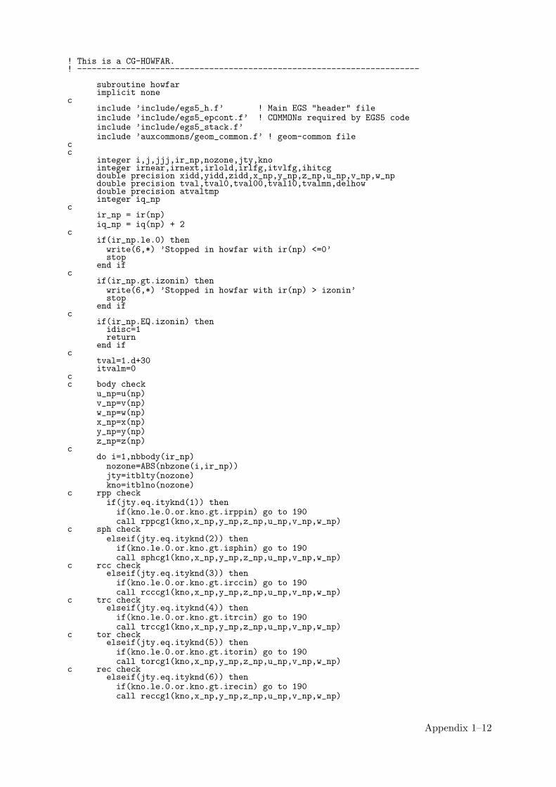
! This is a CG-HOWFAR.! ----------------------------------------------------------------------
subroutine howfarimplicit none
cinclude ’include/egs5_h.f’ ! Main EGS "header" fileinclude ’include/egs5_epcont.f’ ! COMMONs required by EGS5 codeinclude ’include/egs5_stack.f’include ’auxcommons/geom_common.f’ ! geom-common file
cc
integer i,j,jjj,ir_np,nozone,jty,knointeger irnear,irnext,irlold,irlfg,itvlfg,ihitcgdouble precision xidd,yidd,zidd,x_np,y_np,z_np,u_np,v_np,w_npdouble precision tval,tval0,tval00,tval10,tvalmn,delhowdouble precision atvaltmpinteger iq_np
cir_np = ir(np)iq_np = iq(np) + 2
cif(ir_np.le.0) thenwrite(6,*) ’Stopped in howfar with ir(np) <=0’stop
end ifc
if(ir_np.gt.izonin) thenwrite(6,*) ’Stopped in howfar with ir(np) > izonin’stop
end ifc
if(ir_np.EQ.izonin) thenidisc=1return
end ifc
tval=1.d+30itvalm=0
cc body check
u_np=u(np)v_np=v(np)w_np=w(np)x_np=x(np)y_np=y(np)z_np=z(np)
cdo i=1,nbbody(ir_np)nozone=ABS(nbzone(i,ir_np))jty=itblty(nozone)kno=itblno(nozone)
c rpp checkif(jty.eq.ityknd(1)) thenif(kno.le.0.or.kno.gt.irppin) go to 190call rppcg1(kno,x_np,y_np,z_np,u_np,v_np,w_np)
c sph checkelseif(jty.eq.ityknd(2)) thenif(kno.le.0.or.kno.gt.isphin) go to 190call sphcg1(kno,x_np,y_np,z_np,u_np,v_np,w_np)
c rcc checkelseif(jty.eq.ityknd(3)) thenif(kno.le.0.or.kno.gt.irccin) go to 190call rcccg1(kno,x_np,y_np,z_np,u_np,v_np,w_np)
c trc checkelseif(jty.eq.ityknd(4)) thenif(kno.le.0.or.kno.gt.itrcin) go to 190call trccg1(kno,x_np,y_np,z_np,u_np,v_np,w_np)
c tor checkelseif(jty.eq.ityknd(5)) thenif(kno.le.0.or.kno.gt.itorin) go to 190call torcg1(kno,x_np,y_np,z_np,u_np,v_np,w_np)
c rec checkelseif(jty.eq.ityknd(6)) thenif(kno.le.0.or.kno.gt.irecin) go to 190call reccg1(kno,x_np,y_np,z_np,u_np,v_np,w_np)
Appendix 1–12

c ell checkelseif(jty.eq.ityknd(7)) thenif(kno.le.0.or.kno.gt.iellin) go to 190call ellcg1(kno,x_np,y_np,z_np,u_np,v_np,w_np)
c wed checkelseif(jty.eq.ityknd(8)) thenif(kno.le.0.or.kno.gt.iwedin) go to 190call wedcg1(kno,x_np,y_np,z_np,u_np,v_np,w_np)
c box checkelseif(jty.eq.ityknd(9)) thenif(kno.le.0.or.kno.gt.iboxin) go to 190call boxcg1(kno,x_np,y_np,z_np,u_np,v_np,w_np)
c arb checkelseif(jty.eq.ityknd(10)) thenif(kno.le.0.or.kno.gt.iarbin) go to 190call arbcg1(kno,x_np,y_np,z_np,u_np,v_np,w_np)
c hex checkelseif(jty.eq.ityknd(11)) thenif(kno.le.0.or.kno.gt.ihexin) go to 190call hexcg1(kno,x_np,y_np,z_np,u_np,v_np,w_np)
c haf checkelseif(jty.eq.ityknd(12)) thenif(kno.le.0.or.kno.gt.ihafin) go to 190call hafcg1(kno,x_np,y_np,z_np,u_np,v_np,w_np)
c tec checkelseif(jty.eq.ityknd(13)) thenif(kno.le.0.or.kno.gt.itecin) go to 190call teccg1(kno,x_np,y_np,z_np,u_np,v_np,w_np)
c gel checkelseif(jty.eq.ityknd(14)) thenif(kno.le.0.or.kno.gt.igelin) go to 190call gelcg1(kno,x_np,y_np,z_np,u_np,v_np,w_np)
cc**** add new geometry in herec
end if190 continue
end doc
irnear=ir_npif(itvalm.eq.0) thentval0=cgeps1xidd=x_np+tval0*u_npyidd=y_np+tval0*v_npzidd=z_np+tval0*w_np
310 continueif(x_np.ne.xidd.or.y_np.ne.yidd.or.z_np.ne.zidd) goto 320tval0=tval0*10.d0xidd=x_np+tval0*u_npyidd=y_np+tval0*v_npzidd=z_np+tval0*w_npgo to 310
320 continuec write(*,*) ’srzone:1’
call srzone(xidd,yidd,zidd,iq_np,ir_np,irnext)c
if(irnext.ne.ir_np) thentval=0.0d0irnear=irnext
elsetval00=0.0d0tval10=10.0d0*tval0irlold=ir_npirlfg=0
330 continueif(irlfg.eq.1) go to 340tval00=tval00+tval10if(tval00.gt.1.0d+06) thenwrite(6,9000) iq(np),ir(np),x(np),y(np),z(np),
& u(np),v(np),w(np),tval009000 format(’ TVAL00 ERROR : iq,ir,x,y,z,u,v,w,tval=’,
& 2I3,1P7E12.5)stop
end ifxidd=x_np+tval00*u_npyidd=y_np+tval00*v_npzidd=z_np+tval00*w_np
Appendix 1–13

call srzold(xidd,yidd,zidd,irlold,irlfg)go to 330
340 continuec
tval=tval00do j=1,10xidd=x_np+tval00*u_npyidd=y_np+tval00*v_npzidd=z_np+tval00*w_np
c write(*,*) ’srzone:2’call srzone(xidd,yidd,zidd,iq_np,irlold,irnext)if(irnext.ne.irlold) thentval=tval00irnear=irnext
end iftval00=tval00-tval0
end doif(ir_np.eq.irnear) thenwrite(0,*) ’ir(np),tval=’,ir_np,tval
end ifend if
elsedo j=1,itvalm-1do i=j+1,itvalmif(atval(i).lt.atval(j)) thenatvaltmp=atval(i)atval(i)=atval(j)atval(j)=atvaltmp
endifenddo
enddoitvlfg=0tvalmn=tvaldo jjj=1,itvalmif(tvalmn.gt.atval(jjj)) thentvalmn=atval(jjj)
end ifdelhow=cgeps2tval0=atval(jjj)+delhowxidd=x_np+tval0*u_npyidd=y_np+tval0*v_npzidd=z_np+tval0*w_np
410 continueif(x_np.ne.xidd.or.y_np.ne.yidd.or.z_np.ne.zidd) go to 420delhow=delhow*10.d0tval0=atval(jjj)+delhowxidd=x_np+tval0*u_npyidd=y_np+tval0*v_npzidd=z_np+tval0*w_np
go to 410420 continue
c write(*,*) ’srzone:3’call srzone(xidd,yidd,zidd,iq_np,ir_np,irnext)if((irnext.ne.ir_np.or.atval(jjj).ge.1.).and.
& tval.gt.atval(jjj)) THENtval=atval(jjj)irnear=irnextitvlfg=1goto 425
end ifend do
425 continueif(itvlfg.eq.0) thentval0=cgmnstxidd=x_np+tval0*u_npyidd=y_np+tval0*v_npzidd=z_np+tval0*w_np
430 continueif(x_np.ne.xidd.or.y_np.ne.yidd.or.z_np.ne.zidd) go to 440tval0=tval0*10.d0xidd=x_np+tval0*u_npyidd=y_np+tval0*v_npzidd=z_np+tval0*w_npgo to 430
440 continueif(tvalmn.gt.tval0) thentval=tvalmn
elsetval=tval0
Appendix 1–14

end ifend if
end ifihitcg=0if(tval.le.ustep) thenustep=tvalihitcg=1
end ifif(ihitcg.eq.1) THENif(irnear.eq.0) THENwrite(6,9200) iq(np),ir(np),x(np),y(np),z(np),
& u(np),v(np),w(np),tval9200 format(’ TVAL ERROR : iq,ir,x,y,z,u,v,w,tval=’,2I3,1P7E12.5)
idisc=1itverr=itverr+1if(itverr.ge.100) thenstop
end ifreturn
end ifirnew=irnearif(irnew.ne.ir_np) thencall rstnxt(iq_np,ir_np,irnew)
endifend ifreturnend
!--------------------last line of subroutine howfar---------------------!-------------------------------encoea.f--------------------------------! Version: 030831-1300!-----------------------------------------------------------------------!23456789|123456789|123456789|123456789|123456789|123456789|123456789|12!! double precision function encoea(energy)! Function to evaluate the energy absorption coefficient of air.! (Tables and Graphs oh photon mass attenuation coefficients and! energy-absorption coefficients for photon energies 1 keV to! 20 MeV for elements Z=1 to 92 and some dosimetric materials,! S. M. Seltzer and J. H. Hubbell 1995, Japanese Society of! Radiological Technology)!----------------------------------------------------------------------
double precision function encoea(energy)
real*8 hnu(38)/0.001,0.0015,0.002,0.003,0.0032029,0.0032029,* 0.004,0.005,0.006,0.008,0.01,0.015,0.02,0.03,0.04,* 0.05,0.06,0.08,0.10,0.15,0.2,0.3,0.4,0.5,0.6,0.8,1.0,* 1.25,1.5,2.0,3.0,4.0,5.0,6.0,8.0,10.0,15.0,20.0/
real*8 enmu(38)/3599., 1188., 526.2, 161.4, 133.0, 146.0,* 76.36, 39.31, 22.70, 9.446, 4.742, 1.334, 0.5389,* 0.1537,0.06833,0.04098,0.03041,0.02407,0.02325,0.02496,* 0.02672,0.02872,0.02949,0.02966,0.02953,0.02882,0.02789,* 0.02666,0.02547,0.02345,0.02057,0.01870,0.01740,0.01647,* 0.01525,0.01450,0.01353,0.01311/
real*8 energy,enm1,hnu1,ene0,slope
integer i
if (energy.gt.hnu(38)) thenencoea=enmu(38)return
end ifif (energy.lt.hnu(1)) thenencoea=enmu(1)return
end if
do i=1,38if(energy.ge.hnu(i).and.energy.lt.hnu(i+1)) thenenm1=dlog(enmu(i+1))enm0=dlog(enmu(i))hnu1=dlog(hnu(i+1))hnu0=dlog(hnu(i))
ene0=dlog(energy)slope=(enm1-enm0)/(hnu1-hnu0)encoea=exp(enm0+slope*(ene0-hnu0))return
Appendix 1–15

end ifif(energy.eq.hnu(i+1)) thenencoea=enmu(i+1)return
end ifend do
! If sort/interpolation cannot be made, indicate so by writing! a comment and stopping here.
write(6,100) energy100 FORMAT(///,’ *****STOPPED IN ENCOEA*****’,/,’ E=’,G15.5,///)
returnend
!--------------------------last line of encoea.f------------------------!------------------------------decoe.f--------------------------------! Version: 100302-1000!-----------------------------------------------------------------------!23456789|123456789|123456789|123456789|123456789|123456789|123456789|12! ----------------------------------------------------------------------! Function to evaluate the ratio of ambient dose equivalent to air Gy (Sv/Gy).! Data tanken from ICRP pub 74 (1996).! ----------------------------------------------------------------------
double precision function decoe(energy)
implicit none
real*8 energy, slopeinteger i
real*8 hnu(25)/* 0.01,0.015,0.02,0.03,0.04,0.05,0.06,0.08,* 0.10,0.15,0.2,0.3,0.4,0.5,0.6,0.8,1.0,1.5,2.0,* 3.0,4.0,5.0,6.0,8.0,10.0/
real*8 enmu(25)/0.008,0.26,0.61,1.10,1.47,1.67,1.74,1.72,* 1.65,1.49,1.40,1.31,1.26,1.23,1.21,1.19,1.17,1.15,1.14,* 1.13,1.12,1.11,1.11,1.11,1.10/
if(energy.gt.hnu(25)) thendecoe=enmu(25)return
end if
if (energy.lt.hnu(1)) thendecoe=enmu(1)return
end if
do i=1,25if(energy.ge.hnu(i).and.energy.lt.hnu(i+1)) thenslope=(dlog(enmu(i+1))-dlog(enmu(i)))/
* (dlog(hnu(i+1))-dlog(hnu(i)))decoe=dlog(enmu(i))+slope*(dlog(energy)-dlog(hnu(i)))decoe=exp(decoe)return
end ifif(energy.eq.hnu(i+1)) thendecoe=enmu(i+1)return
end ifend do
! If sort/interpolation cannot be made, indicate so by writing! a comment and stopping here.
write(3,100) energy100 format(///,’ **** Stopped in decoe ****’,/,’ E=’,G15.5,///)
stop
returnend
!-------------------------last line of decoe.f------------------------
Appendix 1–16