Embed Size (px)
Citation preview
EFR32MG 2.4 GHz 19.5 dBm Radio BoardBRD4154A Reference Manual
The EFR32MG family of Wireless SoCs deliver a high perform-ance, low energy wireless solution integrated into a small formfactor package.By combining a high performance 2.4 GHz RF transceiver with an energy efficient 32-bitMCU, the family provides designers the ultimate in flexibility with a family of pin-compati-ble devices that scale from 128/256 kB of flash and 16/32 kB of RAM. The ultra-lowpower operating modes and fast wake-up times of the Silicon Labs energy friendly 32-bit MCUs, combined with the low transmit and receive power consumption of the 2.4GHz radio, result in a solution optimized for battery powered applications.
RADIO BOARD FEATURES
• Wireless SoC:EFR32MG1P732F256GM32
• CPU core: ARM Cortex-M4 with FPU• Flash memory: 256 kB + 512 kB• RAM: 32 kB• Operation frequency: 2.4 GHz• Transmit power: 19.5 dBm• Integrated PCB antenna, UFL connector
(optional).• Crystals for LFXO and HFXO: 32.768 kHz
and 38.4 MHz.
To develop and/or evaluate the EFR32 Mighty Gecko the BRD4154A Radio Board canbe connected to the Wireless Starter Kit Mainboard to get access to display, buttons andadditional features from Expansion Boards.
silabs.com | Smart. Connected. Energy-friendly. Rev. 1.0
1. Introduction
The EFR32 Mighty Gecko Radio Boards provide a development platform (together with the Wireless Starter Kit Mainboard) for theSilicon Labs EFR32 Mighty Gecko Wireless System on Chips and serve as reference designs for the matching network of the RF inter-face.
The BRD4154A Radio Board is designed to the operate in the 2400-2483.5 MHz band with the RF matching network optimized to oper-ate with 19.5 dBm output power.
To develop and/or evaluate the EFR32 Mighty Gecko the BRD4154A Radio Board can be connected to the Wireless Starter Kit Main-board to get access to display, buttons and additional features from Expansion Boards and also to evaluate the performance of the RFinterface.
BRD4154A Reference ManualIntroduction
silabs.com | Smart. Connected. Energy-friendly. Rev. 1.0 | 1
2. Radio Board Connector
2.1 Introduction
The board-to-board connector scheme allows access to all EFR32MG1 GPIO pins as well as the RESETn signal. For more informationon the functions of the available pin functions, we refer you to the EFR32MG1 Datasheet.
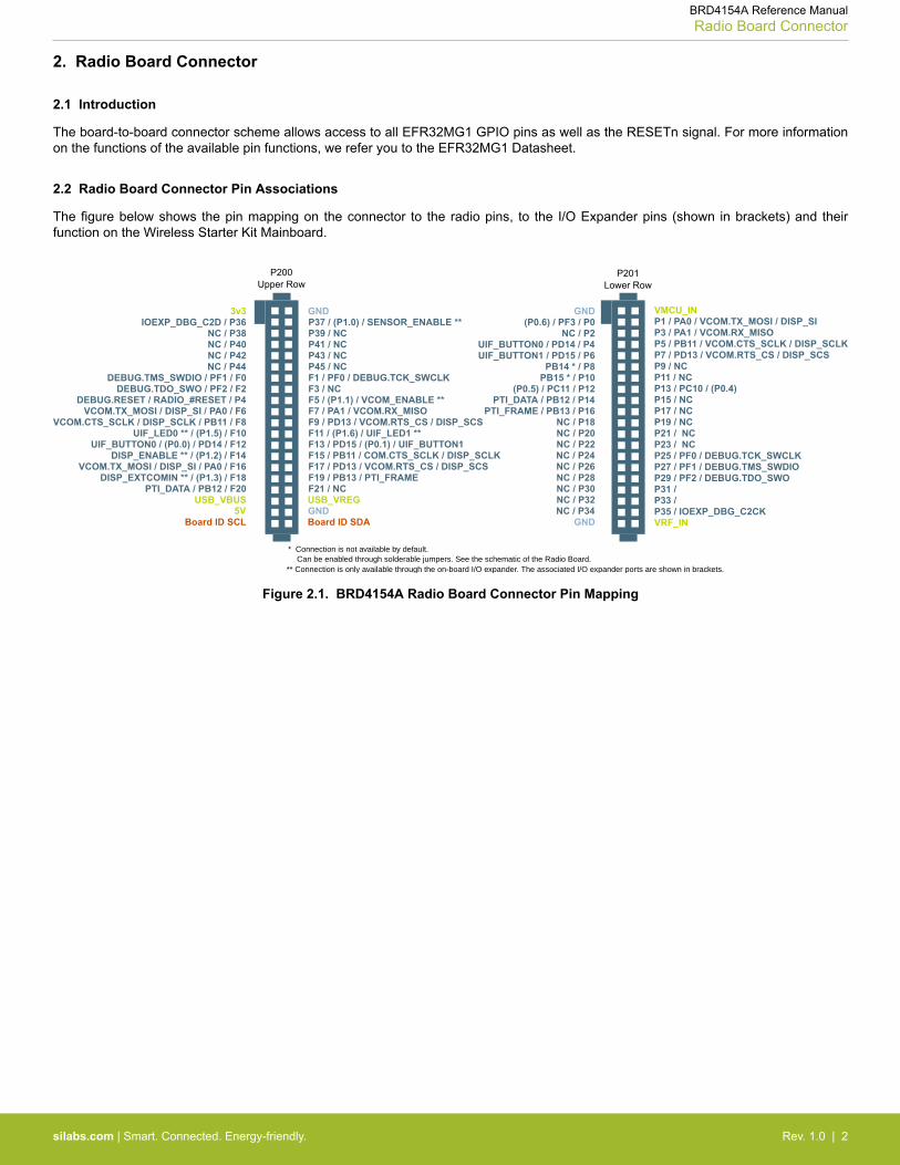
2.2 Radio Board Connector Pin Associations
The figure below shows the pin mapping on the connector to the radio pins, to the I/O Expander pins (shown in brackets) and theirfunction on the Wireless Starter Kit Mainboard.
GND
F9 / PD13 / VCOM.RTS_CS / DISP_SCS
3v3IOEXP_DBG_C2D / P36
P200Upper Row
NC / P38 NC / P40 NC / P42 NC / P44
DEBUG.TMS_SWDIO / PF1 / F0
DISP_ENABLE ** / (P1.2) / F14UIF_BUTTON0 / (P0.0) / PD14 / F12
UIF_LED0 ** / (P1.5) / F10VCOM.CTS_SCLK / DISP_SCLK / PB11 / F8
DEBUG.RESET / RADIO_#RESET / P4DEBUG.TDO_SWO / PF2 / F2
VCOM.TX_MOSI / DISP_SI / PA0 / F16
VCOM.TX_MOSI / DISP_SI / PA0 / F6
PTI_DATA / PB12 / F20DISP_EXTCOMIN ** / (P1.3) / F18
USB_VBUS5V
Board ID SCLGNDBoard ID SDA
USB_VREG
F7 / PA1 / VCOM.RX_MISO F5 / (P1.1) / VCOM_ENABLE **F3 / NC F1 / PF0 / DEBUG.TCK_SWCLK P45 / NC P43 / NC P41 / NC P39 / NC P37 / (P1.0) / SENSOR_ENABLE **
F11 / (P1.6) / UIF_LED1 ** F13 / PD15 / (P0.1) / UIF_BUTTON1 F15 / PB11 / COM.CTS_SCLK / DISP_SCLKF17 / PD13 / VCOM.RTS_CS / DISP_SCS F19 / PB13 / PTI_FRAME F21 / NC
GND VMCU_IN(P0.6) / PF3 / P0
P201Lower Row
NC / P2UIF_BUTTON0 / PD14 / P4UIF_BUTTON1 / PD15 / P6
GND VRF_INP35 / IOEXP_DBG_C2CK
P7 / PD13 / VCOM.RTS_CS / DISP_SCS P5 / PB11 / VCOM.CTS_SCLK / DISP_SCLK P3 / PA1 / VCOM.RX_MISO P1 / PA0 / VCOM.TX_MOSI / DISP_SI
P33 / P31 / P29 / PF2 / DEBUG.TDO_SWO P27 / PF1 / DEBUG.TMS_SWDIO P25 / PF0 / DEBUG.TCK_SWCLK P23 / NC P21 / NC P19 / NC P17 / NC P15 / NC P13 / PC10 / (P0.4) P11 / NC P9 / NC
NC / P34 NC / P32 NC / P30 NC / P28 NC / P26 NC / P24 NC / P22 NC / P20 NC / P18
PTI_FRAME / PB13 / P16 PTI_DATA / PB12 / P14
(P0.5) / PC11 / P12PB15 * / P10PB14 * / P8
* Connection is not available by default. Can be enabled through solderable jumpers. See the schematic of the Radio Board.** Connection is only available through the on-board I/O expander. The associated I/O expander ports are shown in brackets.
Figure 2.1. BRD4154A Radio Board Connector Pin Mapping
BRD4154A Reference ManualRadio Board Connector
silabs.com | Smart. Connected. Energy-friendly. Rev. 1.0 | 2
3. Radio Board Block Summary
3.1 Introduction
This section gives a short introduction to the blocks of the BRD4154A Radio Board.
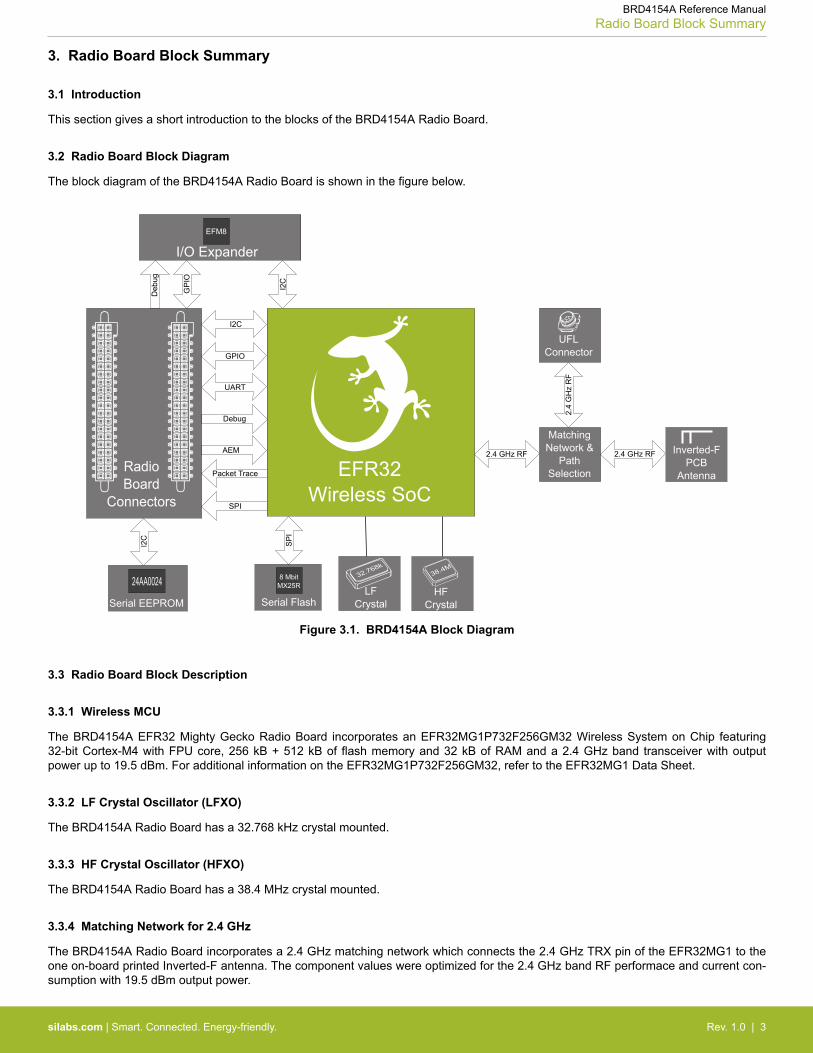
3.2 Radio Board Block Diagram
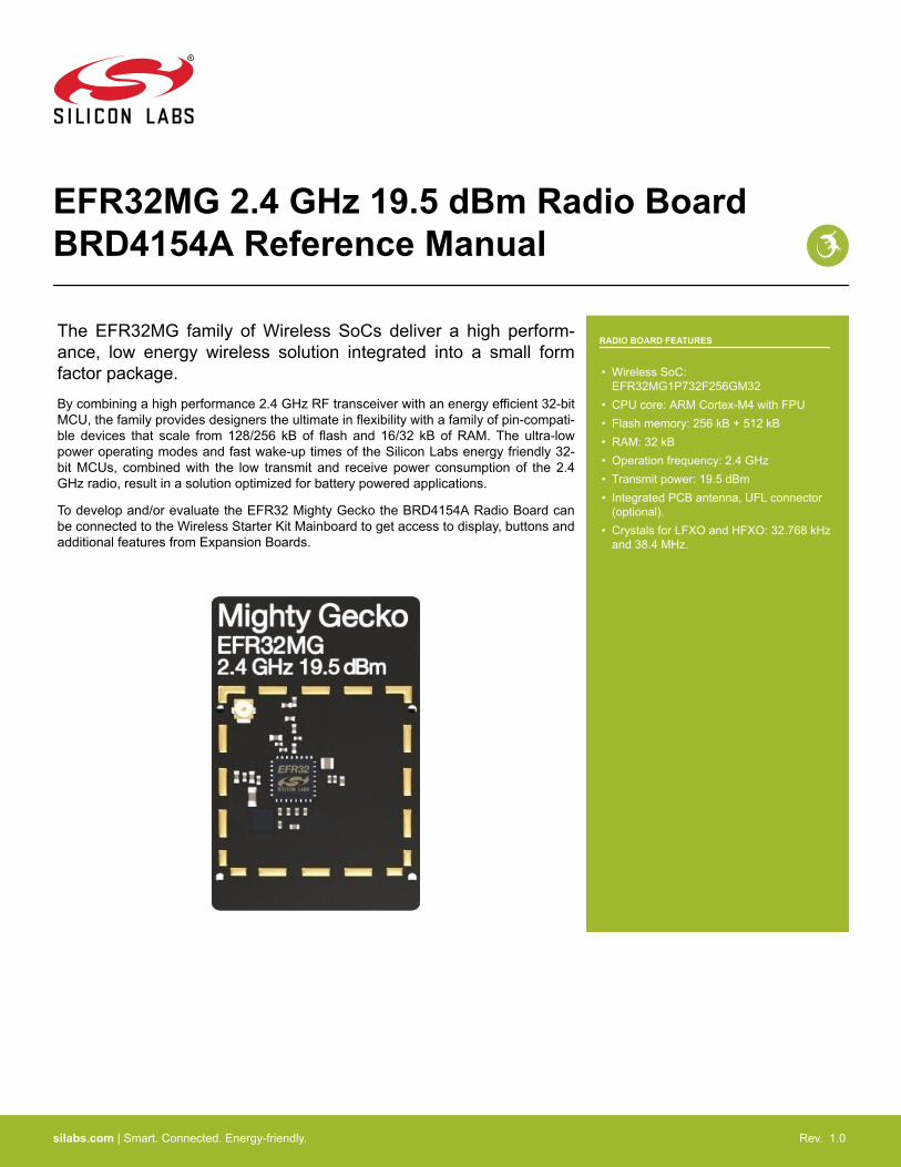
The block diagram of the BRD4154A Radio Board is shown in the figure below.
Inverted-FPCB
Antenna
2.4 GHz RF
UFLConnector
LFCrystal
32.768k
HFCrystal
38.4M
Radio Board
Connectors
8 MbitMX25R
Serial Flash
I2C
24AA0024
Serial EEPROM
MatchingNetwork &
PathSelection
GPIO
UART
Debug
Packet Trace
AEM
I2C
SPI
SP
I
2.4 GHz RF
2.4
GH
z R
F
EFM8
I/O Expander
I2C
Deb
ug
GP
IO
EFR32EFR32Wireless SoC
Figure 3.1. BRD4154A Block Diagram
3.3 Radio Board Block Description
3.3.1 Wireless MCU
The BRD4154A EFR32 Mighty Gecko Radio Board incorporates an EFR32MG1P732F256GM32 Wireless System on Chip featuring32-bit Cortex-M4 with FPU core, 256 kB + 512 kB of flash memory and 32 kB of RAM and a 2.4 GHz band transceiver with outputpower up to 19.5 dBm. For additional information on the EFR32MG1P732F256GM32, refer to the EFR32MG1 Data Sheet.
3.3.2 LF Crystal Oscillator (LFXO)
The BRD4154A Radio Board has a 32.768 kHz crystal mounted.
3.3.3 HF Crystal Oscillator (HFXO)
The BRD4154A Radio Board has a 38.4 MHz crystal mounted.
3.3.4 Matching Network for 2.4 GHz
The BRD4154A Radio Board incorporates a 2.4 GHz matching network which connects the 2.4 GHz TRX pin of the EFR32MG1 to theone on-board printed Inverted-F antenna. The component values were optimized for the 2.4 GHz band RF performace and current con-sumption with 19.5 dBm output power.
BRD4154A Reference ManualRadio Board Block Summary
silabs.com | Smart. Connected. Energy-friendly. Rev. 1.0 | 3
For detailed description of the matching network see Chapter 4.2.1 Description of the 2.4 GHz RF Matching.
3.3.5 Inverted-F Antenna
The BRD4154A Radio Board includes a printed Inverted-F antenna (IFA) tuned to have close to 50 Ohm impedance at the 2.4 GHzband.
For detailed description of the antenna see Chapter 4.5 Inverted-F Antenna.
3.3.6 UFL Connector
To be able to perform conducted measurements Silicon Labs added an UFL connector to the Radio Board. The connector allows anexternal 50 Ohm cable or antenna to be connected during design verification or testing.
Note: By default the output of the matching network is connected to the printed Inverted-F antenna by a series component. It can beconnected to the UFL connector as well through a series 0 Ohm resistor which is not mounted by default. For conducted measurementsthrough the UFL connector the series component to the antenna should be removed and the 0 Ohm resistor should be mounted (seeChapter 4.2 Schematic of the RF Matching Network for further details).
3.3.7 Radio Board Connectors
Two dual-row, 0.05” pitch polarized connectors make up the BRD4154A Radio Board interface to the Wireless Starter Kit Mainboard.
For more information on the pin mapping between the EFR32MG1P732F256GM32 and the Radio Board Connector refer to Chapter2.2 Radio Board Connector Pin Associations.
3.3.8 I/O Expander
Due to the I/O port constraint of the EFR32MG1P732F256GM32 the BRD4154A Radio Board has an EFM8 family MCU mounted as anI/O port expander to be able to utilize additional Wireless Starter Kit Mainboard features (LEDs, display etc.).
For more information on the pin mapping between the I/O Expander and the Radio Board Connector refer to Chapter 2.2 Radio BoardConnector Pin Associations.
BRD4154A Reference ManualRadio Board Block Summary
silabs.com | Smart. Connected. Energy-friendly. Rev. 1.0 | 4
4. RF Section
4.1 Introduction
This section gives a short introduction to the RF section of the BRD4154A.
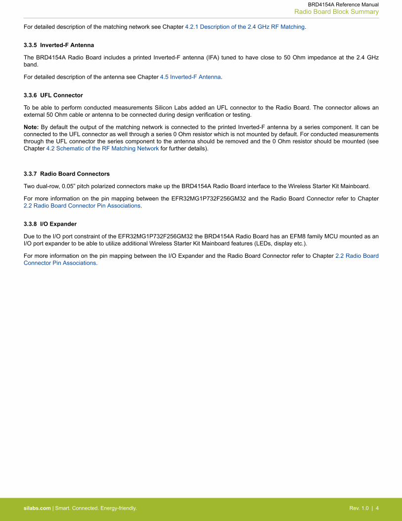
4.2 Schematic of the RF Matching Network
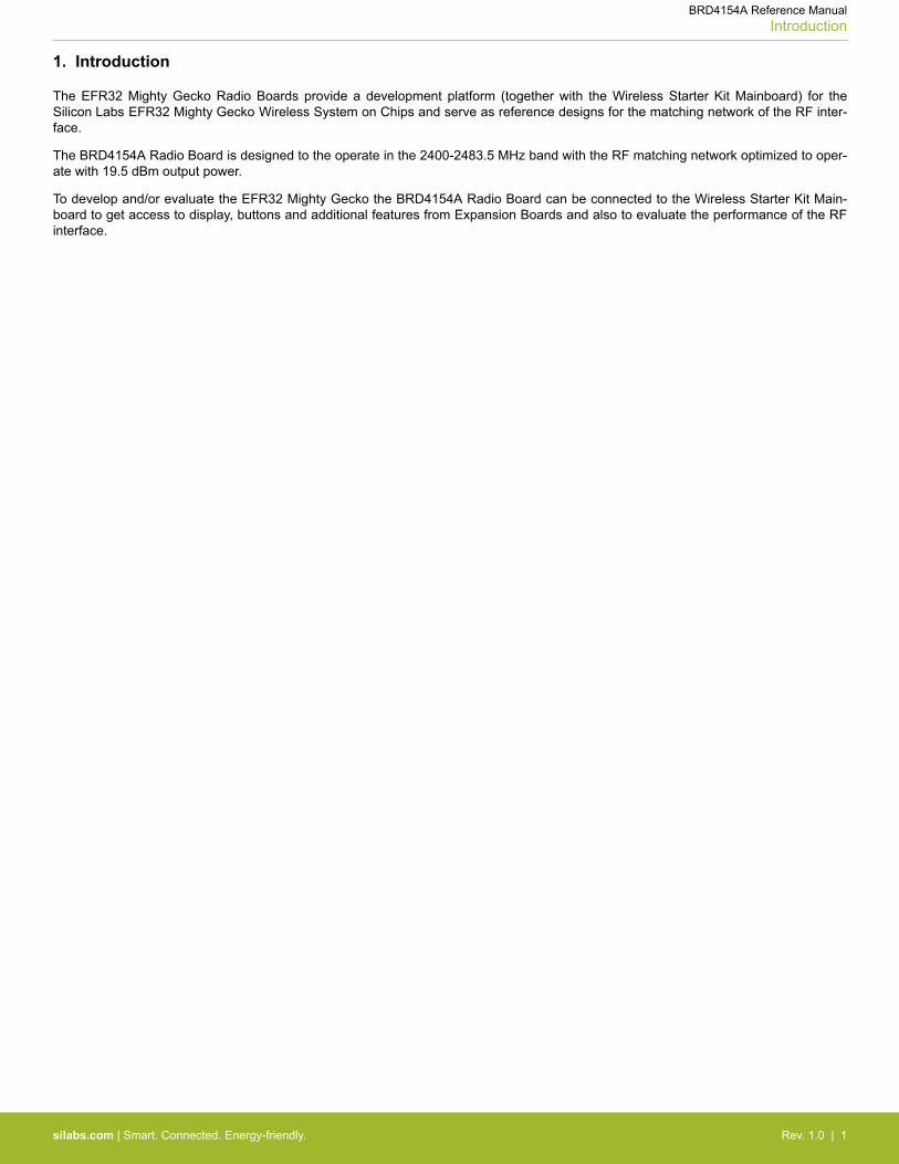
The schematic of the RF section of the BRD4154A Radio Board is shown in the following figure.
GND
GND
GND
L2
P1
U.FL
3
21
C2
Ground
RF I/ORF Crystal
RF Analog Power
PA Power
U1B EFR32
2G4RF_IOP17
2G4RF_ION16
RFVDD9
HFXI10
HFXO11
PAVDD18
RFVSS14
PAVSS15
L1
AT1
INVERTED_F
R2 0RNM
R1
0RC1
PathSelection
Inverted-FAntenna
2.4 GHzMatchingNetwork
TestConnector
TRX Matching & Filter
GND
PAVDD
VDCDC
GND
HFXTAL_P
HFXTAL_N
C107
10P
L102
BLM18AG601SN1
1 2
L103
BLM18AG601SN1
1 2
C102
100P
C103
10P
C106
220N
Supply Filtering
Figure 4.1. Schematic of the RF Section of the BRD4154A
4.2.1 Description of the 2.4 GHz RF Matching
The 2.4 GHz matching connects the 2G4RF_IOP pin to the on-board printed Inverted-F Antenna. The 2G4RF_ION pin is connected toground. For higher output powers (13 dBm and above) beside the impedance matching circuitry it is recommended to use additionalharmonic filtering as well at the RF output. The targeted output power of the BRD4154A board is 19.5 dBm thus the RF output of the ICis connected to the antenna through a four-element impedance matching and harmonic filter circuitry.
For conducted measurements the output of the matching network can also be connected to the UFL connector by relocating the seriesR1 resistor (0 Ohm) to the R2 resistor position between the output of the matching and the UFL connector.
4.3 RF Section Power Supply
On the BRD4154A Radio Board the supply pin of the RF Analog Power (RFVDD) is connected directly ot the output of the on-chip DC-DC converter while the supply for the 2.4 GHz PA (PAVDD) is provided directly by the mainboard. This way, by default, the DC-DCconverter provides 1.8 V for the RF analog section, the mainboard provides 3.3 V for the PA (for details, see the schematic of theBRD4154A).
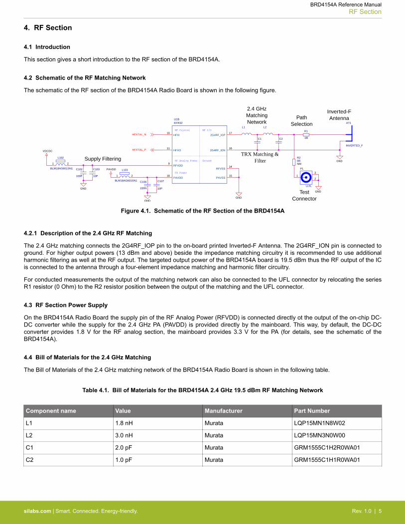
4.4 Bill of Materials for the 2.4 GHz Matching
The Bill of Materials of the 2.4 GHz matching network of the BRD4154A Radio Board is shown in the following table.
Table 4.1. Bill of Materials for the BRD4154A 2.4 GHz 19.5 dBm RF Matching Network
Component name Value Manufacturer Part Number
L1 1.8 nH Murata LQP15MN1N8W02
L2 3.0 nH Murata LQP15MN3N0W00
C1 2.0 pF Murata GRM1555C1H2R0WA01
C2 1.0 pF Murata GRM1555C1H1R0WA01
BRD4154A Reference ManualRF Section
silabs.com | Smart. Connected. Energy-friendly. Rev. 1.0 | 5
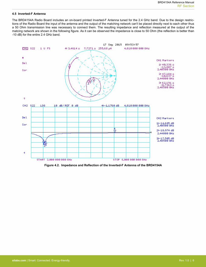
4.5 Inverted-F Antenna
The BRD4154A Radio Board includes an on-board printed Inverted-F Antenna tuned for the 2.4 GHz band. Due to the design restric-tions of the Radio Board the input of the antenna and the output of the matching network can't be placed directly next to each other thusa 50 Ohm transmission line was necessary to connect them. The resulting impedance and reflection measured at the output of thematcing network are shown in the following figure. As it can be observed the impedance is close to 50 Ohm (the reflection is better than-10 dB) for the entire 2.4 GHz band.
Figure 4.2. Impedance and Reflection of the Inverted-F Antenna of the BRD4154A
BRD4154A Reference ManualRF Section
silabs.com | Smart. Connected. Energy-friendly. Rev. 1.0 | 6
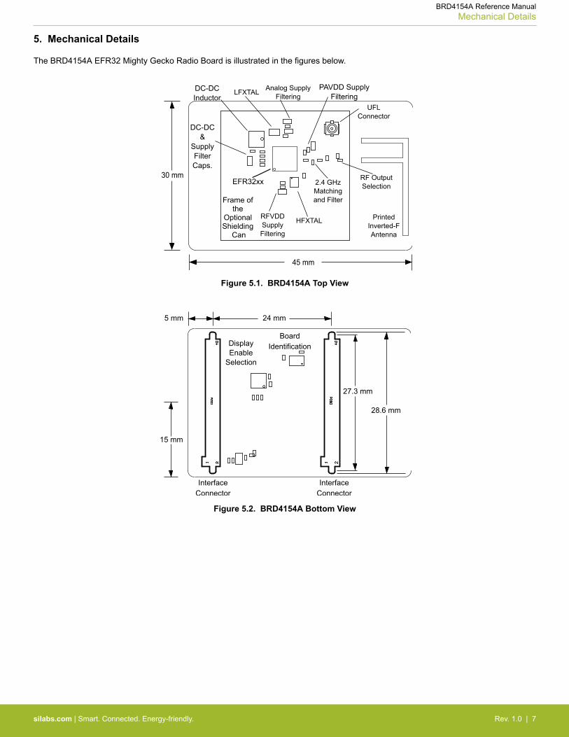
5. Mechanical Details
The BRD4154A EFR32 Mighty Gecko Radio Board is illustrated in the figures below.
EFR32xx
Frame of the
Optional Shielding
Can
45 mm
30 mm
DC-DCInductor
DC-DC&
SupplyFilterCaps.
PAVDD SupplyFiltering
Figure 5.1. BRD4154A Top View
24 mm
27.3 mm
28.6 mm
5 mm
InterfaceConnector
InterfaceConnector
15 mm
BoardIdentificationDisplay
EnableSelection
Figure 5.2. BRD4154A Bottom View
BRD4154A Reference ManualMechanical Details
silabs.com | Smart. Connected. Energy-friendly. Rev. 1.0 | 7
6. EMC Compliance
6.1 Introduction
Compliance of the fundamental and harmonic levels is tested against the following standards:
• 2.4 GHz:• ETSI EN 300-328• FCC 15.247
6.2 EMC Regulations for 2.4 GHz
6.2.1 ETSI EN 300-328 Emission Limits for the 2400-2483.5 MHz Band
Based on ETSI EN 300-328 the allowed maximum fundamental power for the 2400-2483.5 MHz band is 20 dBm EIRP. For the unwan-ted emissions in the 1 GHz to 12.75 GHz domain the specified limit is -30 dBm EIRP.
6.2.2 FCC15.247 Emission Limits for the 2400-2483.5 MHz Band
FCC 15.247 allows conducted output power up to 1 Watt (30 dBm) in the 2400-2483.5 MHz band. For spurious emmissions the limit is-20 dBc based on either conducted or radiated measurement, if the emission is not in a restricted band. The restricted bands are speci-fied in FCC 15.205. In these bands the spurious emission levels must meet the levels set out in FCC 15.209. In the range from960 MHz to the frequency of the 5th harmonic it is defined as 0.5 mV/m at 3 m distance (equals to -41.2 dBm in EIRP).
Additionally, for spurious frequencies above 1 GHz FCC 15.35 allows duty-cycle relaxation to the regulatory limits. For the EmberZNetPRO the relaxation is 3.6 dB. So practically the -41.2 dBm limit can be modified to -37.6 dBm.
In case of operating in the 2400-2483.5 MHz band the 2nd, 3rd and 5th harmonics can fall into restricted bands so for those the-37.6 dBm limit should be applied. For the 4th harmonic the -20 dBc limit should be applied.
6.2.3 Applied Emission Limits for the 2.4 GHz Band
The above ETSI limits are applied both for conducted and radiated measurements.
The FCC restricted band limits are radiated limits only. Besides that, Silicon Labs applies those to the conducted spectrum i.e. it is as-sumed that in case of a custom board an antenna is used which has 0 dB gain at the fundamental and the harmonic frequencies. In thattheoretical case, based on the conducted measurement, the compliance with the radiated limits can be estimated.
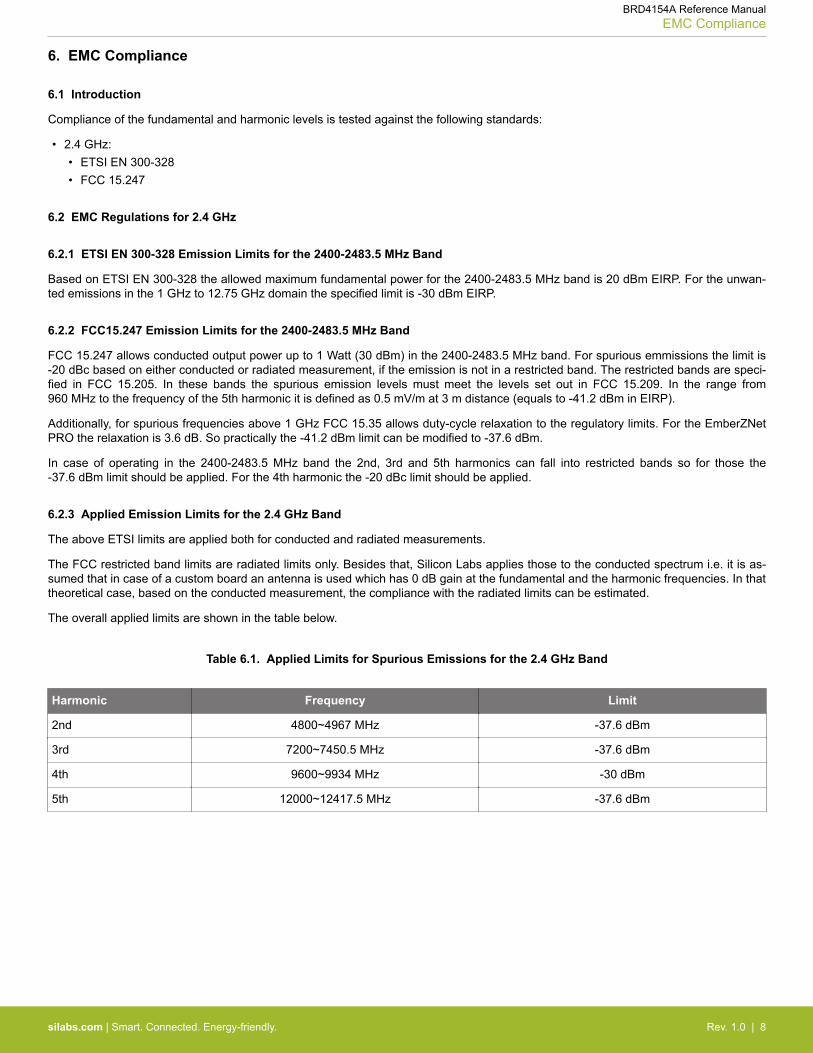
The overall applied limits are shown in the table below.
Table 6.1. Applied Limits for Spurious Emissions for the 2.4 GHz Band
Harmonic Frequency Limit
2nd 4800~4967 MHz -37.6 dBm
3rd 7200~7450.5 MHz -37.6 dBm
4th 9600~9934 MHz -30 dBm
5th 12000~12417.5 MHz -37.6 dBm
BRD4154A Reference ManualEMC Compliance
silabs.com | Smart. Connected. Energy-friendly. Rev. 1.0 | 8
7. RF Performance
7.1 Conducted Power Measurements
During measurements the BRD4154A Radio Board was attached to a Wireless Starter Kit Mainboard which was supplied by USB. Thevoltage supply for the Radio Board was 3.3 V.
7.1.1 Conducted Measurements in the 2.4 GHz band
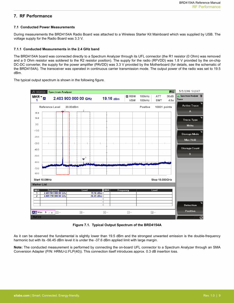
The BRD4154A board was connected directly to a Spectrum Analyzer through its UFL connector (the R1 resistor (0 Ohm) was removedand a 0 Ohm resistor was soldered to the R2 resistor position). The supply for the radio (RFVDD) was 1.8 V provided by the on-chipDC-DC converter, the supply for the power amplifier (PAVDD) was 3.3 V provided by the Motherboard (for details, see the schematic ofthe BRD4154A). The transceiver was operated in continuous carrier transmission mode. The output power of the radio was set to 19.5dBm.
The typical output spectrum is shown in the following figure.
Figure 7.1. Typical Output Spectrum of the BRD4154A
As it can be observed the fundamental is slightly lower than 19.5 dBm and the strongest unwanted emission is the double-frequencyharmonic but with its -56.45 dBm level it is under the -37.6 dBm applied limit with large margin.
Note: The conducted measurement is performed by connecting the on-board UFL connector to a Spectrum Analyzer through an SMAConversion Adapter (P/N: HRMJ-U.FLP(40)). This connection itself introduces approx. 0.3 dB insertion loss.
BRD4154A Reference ManualRF Performance
silabs.com | Smart. Connected. Energy-friendly. Rev. 1.0 | 9
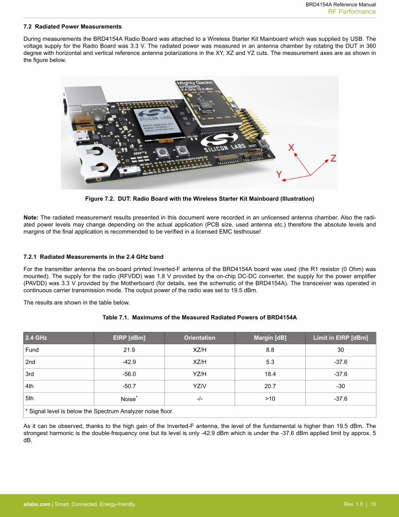
7.2 Radiated Power Measurements
During measurements the BRD4154A Radio Board was attached to a Wireless Starter Kit Mainboard which was supplied by USB. Thevoltage supply for the Radio Board was 3.3 V. The radiated power was measured in an antenna chamber by rotating the DUT in 360degree with horizontal and vertical reference antenna polarizations in the XY, XZ and YZ cuts. The measurement axes are as shown inthe figure below.
Figure 7.2. DUT: Radio Board with the Wireless Starter Kit Mainboard (Illustration)
Note: The radiated measurement results presented in this document were recorded in an unlicensed antenna chamber. Also the radi-ated power levels may change depending on the actual application (PCB size, used antenna etc.) therefore the absolute levels andmargins of the final application is recommended to be verified in a licensed EMC testhouse!
7.2.1 Radiated Measurements in the 2.4 GHz band
For the transmitter antenna the on-board printed Inverted-F antenna of the BRD4154A board was used (the R1 resistor (0 Ohm) wasmounted). The supply for the radio (RFVDD) was 1.8 V provided by the on-chip DC-DC converter, the supply for the power amplifier(PAVDD) was 3.3 V provided by the Motherboard (for details, see the schematic of the BRD4154A). The transceiver was operated incontinuous carrier transmission mode. The output power of the radio was set to 19.5 dBm.
The results are shown in the table below.
Table 7.1. Maximums of the Measured Radiated Powers of BRD4154A
2.4 GHz EIRP [dBm] Orientation Margin [dB] Limit in EIRP [dBm]
Fund 21.9 XZ/H 8.8 30
2nd -42.9 XZ/H 5.3 -37.6
3rd -56.0 YZ/H 18.4 -37.6
4th -50.7 YZ/V 20.7 -30
5th Noise* -/- >10 -37.6
* Signal level is below the Spectrum Analyzer noise floor.
As it can be observed, thanks to the high gain of the Inverted-F antenna, the level of the fundamental is higher than 19.5 dBm. Thestrongest harmonic is the double-frequency one but its level is only -42.9 dBm which is under the -37.6 dBm applied limit by approx. 5dB.
BRD4154A Reference ManualRF Performance
silabs.com | Smart. Connected. Energy-friendly. Rev. 1.0 | 10
8. EMC Compliance Recommendations
8.1 Recommendations for 2.4 GHz ETSI EN 300-328 compliance
As it was shown in the previous chapter the radiated power of the fundamental of the BRD4154A EFR32 Mighty Gecko Radio Boardcomplies with the 20 dBm limit of the ETSI EN 300-328 in case of the conducted measurement but due to the high antenna gain theradiated power is higher than the limit by approx. 2 dB. In order to comply the output power should be reduced (with different antennas,depending on the gain of the used antenna, the necessary reduction can be different). The harmonic emissions are under the -30 dBmlimit with margin. Although the BRD4154A Radio Board has an option for mounting a shielding can, that is not required for the compli-ance.
8.2 Recommendations for 2.4 GHz FCC 15.247 compliance
As it was shown in the previous chapter the radiated power of the fundamental of the BRD4154A EFR32 Mighty Gecko Radio Boardcomplies with the 30 dBm limit of the FCC 15.247. The harmonic emissions are under the -37.6 dBm applied limit both in case of theconducted and the radiated measurements. Although the BRD4154A Radio Board has an option for mounting a shielding can, that isnot required for the compliance.
BRD4154A Reference ManualEMC Compliance Recommendations
silabs.com | Smart. Connected. Energy-friendly. Rev. 1.0 | 11
9. Revision History
Table 9.1. Document Revision History
Revision Number Effective Date Change Description
1.0 06.05.2016 Initial release.
BRD4154A Reference ManualRevision History
silabs.com | Smart. Connected. Energy-friendly. Rev. 1.0 | 12
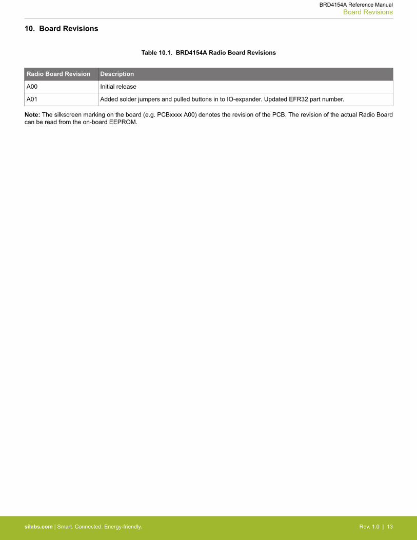
10. Board Revisions
Table 10.1. BRD4154A Radio Board Revisions
Radio Board Revision Description
A00 Initial release
A01 Added solder jumpers and pulled buttons in to IO-expander. Updated EFR32 part number.
Note: The silkscreen marking on the board (e.g. PCBxxxx A00) denotes the revision of the PCB. The revision of the actual Radio Boardcan be read from the on-board EEPROM.
BRD4154A Reference ManualBoard Revisions
silabs.com | Smart. Connected. Energy-friendly. Rev. 1.0 | 13
Table of Contents1. Introduction . . . . . . . . . . . . . . . . . . . . . . . . . . . . . . . . 1
2. Radio Board Connector . . . . . . . . . . . . . . . . . . . . . . . . . . . 22.1 Introduction. . . . . . . . . . . . . . . . . . . . . . . . . . . . . . . 2
2.2 Radio Board Connector Pin Associations. . . . . . . . . . . . . . . . . . . . . 2
3. Radio Board Block Summary . . . . . . . . . . . . . . . . . . . . . . . . . 33.1 Introduction. . . . . . . . . . . . . . . . . . . . . . . . . . . . . . . 3
3.2 Radio Board Block Diagram . . . . . . . . . . . . . . . . . . . . . . . . . 3
3.3 Radio Board Block Description . . . . . . . . . . . . . . . . . . . . . . . . 33.3.1 Wireless MCU . . . . . . . . . . . . . . . . . . . . . . . . . . . . . 33.3.2 LF Crystal Oscillator (LFXO) . . . . . . . . . . . . . . . . . . . . . . . . 33.3.3 HF Crystal Oscillator (HFXO) . . . . . . . . . . . . . . . . . . . . . . . . 33.3.4 Matching Network for 2.4 GHz. . . . . . . . . . . . . . . . . . . . . . . . 33.3.5 Inverted-F Antenna . . . . . . . . . . . . . . . . . . . . . . . . . . . 43.3.6 UFL Connector . . . . . . . . . . . . . . . . . . . . . . . . . . . . . 43.3.7 Radio Board Connectors . . . . . . . . . . . . . . . . . . . . . . . . . 43.3.8 I/O Expander . . . . . . . . . . . . . . . . . . . . . . . . . . . . . 4
4. RF Section . . . . . . . . . . . . . . . . . . . . . . . . . . . . . . . . 54.1 Introduction. . . . . . . . . . . . . . . . . . . . . . . . . . . . . . . 5
4.2 Schematic of the RF Matching Network . . . . . . . . . . . . . . . . . . . . . 54.2.1 Description of the 2.4 GHz RF Matching . . . . . . . . . . . . . . . . . . . . 5
4.3 RF Section Power Supply . . . . . . . . . . . . . . . . . . . . . . . . . . 5
4.4 Bill of Materials for the 2.4 GHz Matching . . . . . . . . . . . . . . . . . . . . 5
4.5 Inverted-F Antenna . . . . . . . . . . . . . . . . . . . . . . . . . . . . 6
5. Mechanical Details . . . . . . . . . . . . . . . . . . . . . . . . . . . . . 7
6. EMC Compliance . . . . . . . . . . . . . . . . . . . . . . . . . . . . . . 86.1 Introduction. . . . . . . . . . . . . . . . . . . . . . . . . . . . . . . 8
6.2 EMC Regulations for 2.4 GHz . . . . . . . . . . . . . . . . . . . . . . . . 86.2.1 ETSI EN 300-328 Emission Limits for the 2400-2483.5 MHz Band . . . . . . . . . . . 86.2.2 FCC15.247 Emission Limits for the 2400-2483.5 MHz Band. . . . . . . . . . . . . . 86.2.3 Applied Emission Limits for the 2.4 GHz Band . . . . . . . . . . . . . . . . . . 8
7. RF Performance . . . . . . . . . . . . . . . . . . . . . . . . . . . . . . 97.1 Conducted Power Measurements . . . . . . . . . . . . . . . . . . . . . . . 97.1.1 Conducted Measurements in the 2.4 GHz band . . . . . . . . . . . . . . . . . . 9
7.2 Radiated Power Measurements . . . . . . . . . . . . . . . . . . . . . . . .107.2.1 Radiated Measurements in the 2.4 GHz band . . . . . . . . . . . . . . . . . .10
8. EMC Compliance Recommendations . . . . . . . . . . . . . . . . . . . . . .118.1 Recommendations for 2.4 GHz ETSI EN 300-328 compliance . . . . . . . . . . . . .11
8.2 Recommendations for 2.4 GHz FCC 15.247 compliance . . . . . . . . . . . . . . .11
Table of Contents 14
9. Revision History . . . . . . . . . . . . . . . . . . . . . . . . . . . . . 12
10. Board Revisions. . . . . . . . . . . . . . . . . . . . . . . . . . . . . 13
Table of Contents . . . . . . . . . . . . . . . . . . . . . . . . . . . . . . 14
Table of Contents 15
http://www.silabs.com
Silicon Laboratories Inc.400 West Cesar ChavezAustin, TX 78701USA
Simplicity StudioOne-click access to MCU and wireless tools, documentation, software, source code libraries & more. Available for Windows, Mac and Linux!
IoT Portfoliowww.silabs.com/IoT
SW/HWwww.silabs.com/simplicity
Qualitywww.silabs.com/quality
Support and Communitycommunity.silabs.com
DisclaimerSilicon Laboratories intends to provide customers with the latest, accurate, and in-depth documentation of all peripherals and modules available for system and software implementers using or intending to use the Silicon Laboratories products. Characterization data, available modules and peripherals, memory sizes and memory addresses refer to each specific device, and "Typical" parameters provided can and do vary in different applications. Application examples described herein are for illustrative purposes only. Silicon Laboratories reserves the right to make changes without further notice and limitation to product information, specifications, and descriptions herein, and does not give warranties as to the accuracy or completeness of the included information. Silicon Laboratories shall have no liability for the consequences of use of the information supplied herein. This document does not imply or express copyright licenses granted hereunder to design or fabricate any integrated circuits. The products are not designed or authorized to be used within any Life Support System without the specific written consent of Silicon Laboratories. A "Life Support System" is any product or system intended to support or sustain life and/or health, which, if it fails, can be reasonably expected to result in significant personal injury or death. Silicon Laboratories products are not designed or authorized for military applications. Silicon Laboratories products shall under no circumstances be used in weapons of mass destruction including (but not limited to) nuclear, biological or chemical weapons, or missiles capable of delivering such weapons.
Trademark InformationSilicon Laboratories Inc.® , Silicon Laboratories®, Silicon Labs®, SiLabs® and the Silicon Labs logo®, Bluegiga®, Bluegiga Logo®, Clockbuilder®, CMEMS®, DSPLL®, EFM®, EFM32®, EFR, Ember®, Energy Micro, Energy Micro logo and combinations thereof, "the world’s most energy friendly microcontrollers", Ember®, EZLink®, EZRadio®, EZRadioPRO®, Gecko®, ISOmodem®, Precision32®, ProSLIC®, Simplicity Studio®, SiPHY®, Telegesis, the Telegesis Logo®, USBXpress® and others are trademarks or registered trademarks of Silicon Laborato-ries Inc. ARM, CORTEX, Cortex-M3 and THUMB are trademarks or registered trademarks of ARM Holdings. Keil is a registered trademark of ARM Limited. All other products or brand names mentioned herein are trademarks of their respective holders.