Embed Size (px)
Citation preview
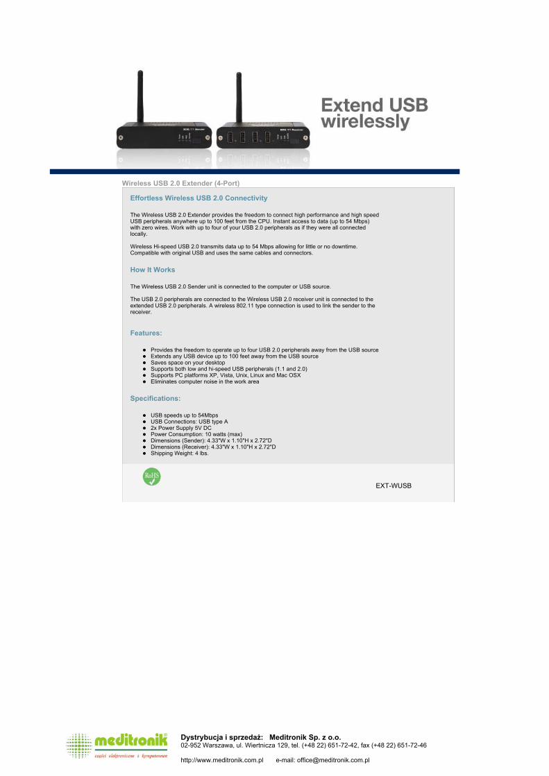
Wireless USB 2.0 Extender (4-Port)
Effortless Wireless USB 2.0 Connectivity
The Wireless USB 2.0 Extender provides the freedom to connect high performance and high speed USB peripherals anywhere up to 100 feet from the CPU. Instant access to data (up to 54 Mbps) with zero wires. Work with up to four of your USB 2.0 peripherals as if they were all connected locally. Wireless Hi-speed USB 2.0 transmits data up to 54 Mbps allowing for little or no downtime. Compatible with original USB and uses the same cables and connectors.
How It Works
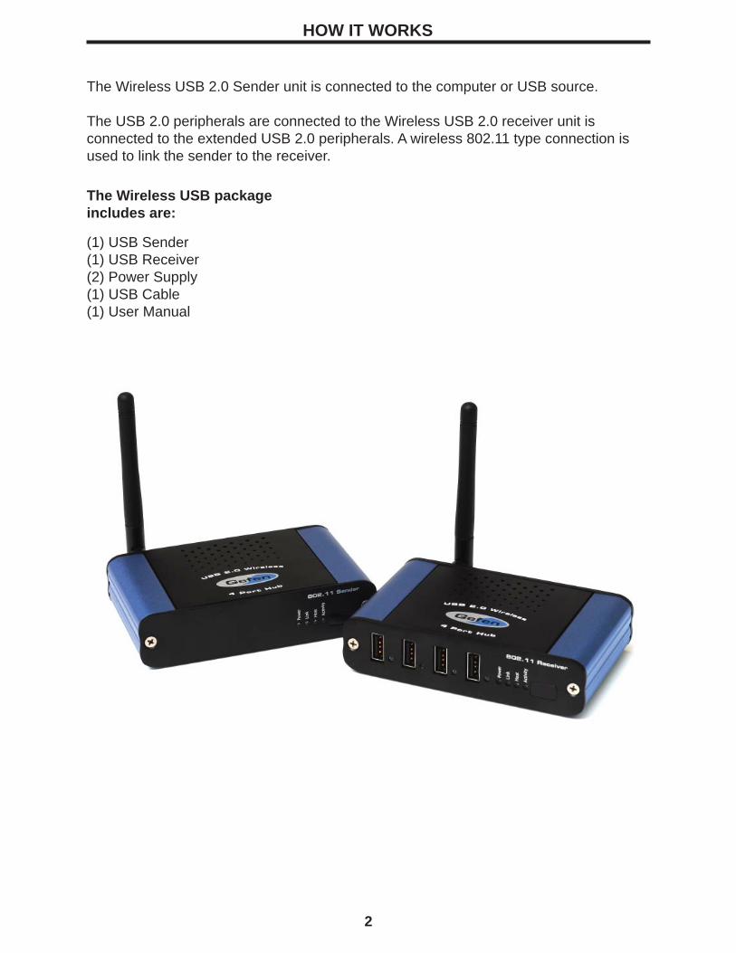
The Wireless USB 2.0 Sender unit is connected to the computer or USB source.
The USB 2.0 peripherals are connected to the Wireless USB 2.0 receiver unit is connected to the extended USB 2.0 peripherals. A wireless 802.11 type connection is used to link the sender to the receiver.
Features:
Provides the freedom to operate up to four USB 2.0 peripherals away from the USB source
Extends any USB device up to 100 feet away from the USB source Saves space on your desktop Supports both low and hi-speed USB peripherals (1.1 and 2.0) Supports PC platforms XP, Vista, Unix, Linux and Mac OSX Eliminates computer noise in the work area
Specifications:
USB speeds up to 54Mbps
USB Connections: USB type A 2x Power Supply 5V DC Power Consumption: 10 watts (max) Dimensions (Sender): 4.33"W x 1.10"H x 2.72"D Dimensions (Receiver): 4.33"W x 1.10"H x 2.72"D Shipping Weight: 4 lbs.
EXT-WUSB
Dystrybucja i sprzedaż: Meditronik Sp. z o.o. 02-952 Warszawa, ul. Wiertnicza 129, tel. (+48 22) 651-72-42, fax (+48 22) 651-72-46
http://www.meditronik.com.pl e-mail: [email protected]
Wireless USB 2.0 ExtenderU S E R M A N U A L
www.gefen.com
ASKING FOR ASSISTANCE
Technical Support:
Telephone (818) 772-9100 (800) 545-6900Fax (818) 772-9120
Technical Support Hours:8:00am to 5:00pmMonday thru Friday
Write To:
Gefen, Inc.c/o Customer Service20600 Nordhoff St. Chatsworth, CA 91331
© 2007 Gefen Inc., All Rights Reserved
NoticeGefen Inc. reserves the right to make changes in the hard ware, packaging and any
accompanying doc u men ta tion without prior written notice.
Wireless USB 2.0 Extender is a trademark of Gefen Inc.
TABLE OF CONTENTS
Introduction
How It Works
Panel Layout
Before You Begin / Connecting Wireless USB Hub / Establishing Wireless Communication
Checking the Installation
Viewing and Changing the 802.11g Radio Channel
Changing the 802.11g Radio Channel
Changing the 802.11g Radio Channel
Pairing a Wireless USB 2.0 Sender and Receiver Pairing a Wireless USB 2.0 Sender and Receiver / Maintenance / Troubleshooting
Maintenance / Troubleshooting
Maintenance / Troubleshooting
Maintenance / Troubleshooting
Maintenance / Troubleshooting
Specifi cations
Warranty
1
2
3
4
5
6
7
8
9
10
11
12
13
14
15
16
This manual explains the installation and operation of the Wireless USB 2.0 Extender. The instructions in this guide assume a general knowledge of computer installation procedures, wireless network installation requirements, and some understanding of USB devices.
NOTE: Notes give additional information that could make installation easier.
To complete the installation, you will also require the following items that are not included with the product:• USB 1.1 or 2.0 compatible computer• USB device(s)
NOTE: The Wireless USB 2.0 Extender uses an IEEE 802.11g radio platform to wirelessly communicate between the Wireless USB 2.0 Sender unit and the Wireless USB 2.0 Receiver unit using the 2.4GHz radio frequency range. Other products, such as wireless routers and 2.4GHz cordless telephones, also broadcast in this same 2.4GHz range. Please be aware of potential interference issues with such products before you begin installation of the Wireless USB 2.0 Extender.
NOTE: The Wireless USB 2.0 Sender unit and the Wireless USB 2.0 Receiver unit of your new Wireless USB 2.0 Extender have been “Paired” during manufacturing. This means that they will only communicate with each other, even if other Wireless USB 2.0 Extender units are installed near by.
NOTE: Use only the AC adapters supplied with the Wireless USB 2.0 Extender. Use of substitute adapters may cause permanent damage to the system and will void the warranty.
The Wireless USB 2.0 Extender provides the freedom to connect high performance and high speed USB peripherals anywhere up to 100 feet from the CPU. Instant access to data (up to 54 Mbps) with zero wires. Work with your USB 2.0 peripherals as if they were all connected locally.
Wireless Hi-speed USB 2.0 transmits data up to 54 Mbps allowing for little or no downtime. Compatible with original USB and uses the same cables and connectors.
READ THESE NOTES BEFORE INSTALLING OROPERATING THE USB 2.0 EXTENDER SYSTEM.
* The wireless USB extender does not support isochronous USB.
* In order to operate properly, the Wireless USB 2.0 Extender sender and receiver units must not exceed 100 feet.
* To prevent interference, keep sender and receiver in plain sight of each other.
INTRODUCTION
1
HOW IT WORKS
The Wireless USB 2.0 Sender unit is connected to the computer or USB source.
The USB 2.0 peripherals are connected to the Wireless USB 2.0 receiver unit is connected to the extended USB 2.0 peripherals. A wireless 802.11 type connection is used to link the sender to the receiver.
2
The Wireless USB package includes are:
(1) USB Sender(1) USB Receiver(2) Power Supply(1) USB Cable(1) User Manual
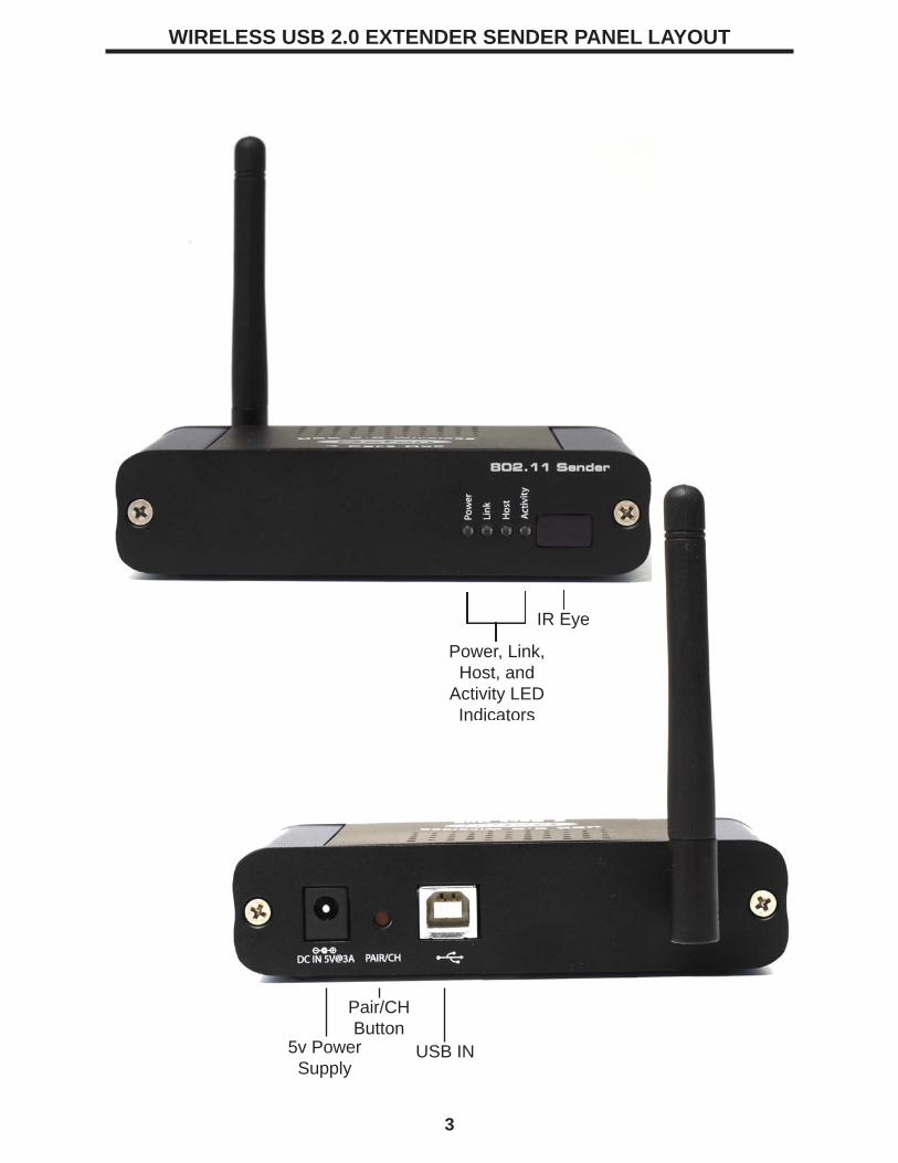
WIRELESS USB 2.0 EXTENDER SENDER PANEL LAYOUT
3
Power, Link, Host, and
Activity LED Indicators
IR Eye
5v Power Supply
Pair/CHButton
USB IN
Power, Link, Host, and
Activity LED Indicators
IR Eye
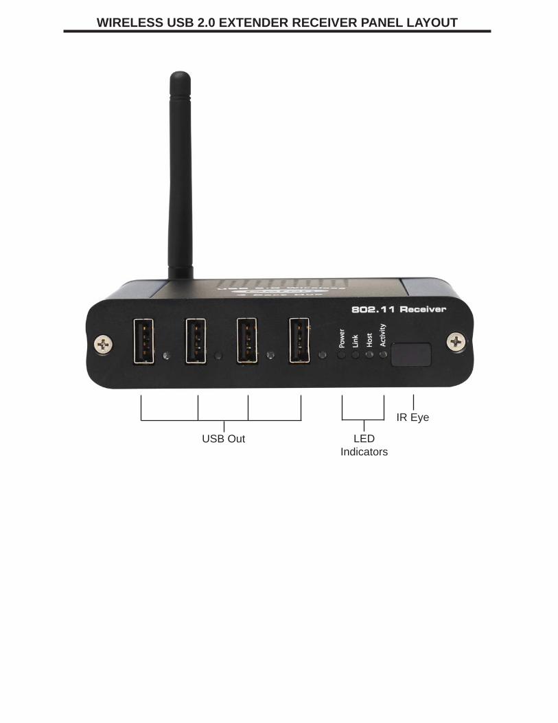
WIRELESS USB 2.0 EXTENDER RECEIVER PANEL LAYOUT
USB Out LED Indicators
IR Eye
CONNECTING THE WIRELESS HUB
1.
2.
3.
4.
5.
6.
7.
8.
Place the sender unit near the host computer.
Plug the Type-B connector on the USB cable (included) into the Host port on the sender unit.
Plug the Type-A connector on the USB cable into the USB port on the computer.
Plug the power adapter into a suitable AC outlet.
Connect the power adapter to the sender unit.
Place the receiver unit near the USB device(s), no more than 30m from the sender unit.
Plug the power adapter into a suitable AC outlet.
Connect the power adapter to the receiver unit.
4
ESTABLISHING WIRELESS COMMUNICATION
The Wireless USB 2.0 Extender will automatically establish a wireless connection between the Wireless USB 2.0 Sender unit and the Wireless USB 2.0 Receiver unit once power is applied to both units and they are located within their operating range. The Link LED on both units will turn on once the wireless connection has been made.
NOTE: It may take up to 30 seconds for the Wireless USB 2.0 Extender to establish wireless communication. The Activity LED will fl ash during this time to indicate that the radios are powering up.
1.
2.
3.
4.
Set up the host computer in an appropriate location.
Determine where you want to locate the USB device(s).
Determine suitable locations for the Wireless USB 2.0 Sender unit and the Wireless USB 2.0 Receiver unit such that they will be able to maintain wireless communication. Physical obstacles and other radio wave emitting devices can cause interference that will reduce the maximum distance and data rate between the Wireless USB 2.0 Sender unit and the Wireless USB 2.0 Receiver unit.
If other 802.11g based products will be in operation in the same area, determine the optimal Radio Channel selection for all wireless products. See the Wireless Operation section on Page 5 for more information on channel selection.Plug the power adapter into a suitable AC outlet.
BEFORE YOU BEGIN
5
CHECKING THE INSTALLATION
Once the Activity LED’s on the Wireless USB 2.0 Sender unit and Wireless USB 2.0
1.
2.
3.
4.
Check that the Power LED’s on the Wireless USB 2.0 Sender unit and Wireless USB 2.0 Receiver unit are both on.
Check that the Link LED’s on the Wireless USB 2.0 Sender unit and Wireless USB 2.0 Receiver unit are both on.
Check that the Host LED’s on the Wireless USB 2.0 Sender unit and Wireless USB 2.0 Receiver unit are both on.
For Windows users (2000, XP, or Vista) open Device Manager to confi rm that the Wireless USB 2.0 Extender has installed correctly. Expand the entry for Universal Serial Bus controllers by clicking the + sign. If the Wireless USB 2.0 Extender has been installed correctly you should fi nd it listed as a Generic USB Hub.
5. For Mac OS X users open the System Profi ler to confi rm that the Wireless USB 2.0 Extender has installed correctly. In the left hand column under Hardware, select “USB” and inspect the right hand panel. If the Wireless USB 2.0 Extender has been installed correctly you should fi nd it listed as a Hub under the USB High-Speed Bus.
NOTE: To open System Profi ler in OS X: Open the Finder, select Applications, then open the Utilities folder and double click on the System Profi ler icon.
CONNECTING A USB DEVICE
1.
2.
3.
4.
Install any software required to operate the USB device(s). Refer to the documentation for the device(s), as required.
Connect the USB device(s) to the Device port(s) on the Wireless USB 2.0 Receiver unit.
Check that the Device LED on the Wireless USB 2.0 Receiver unit is on.
Confi rm on the host PC that the each connected device operates as expected.
NOTE: To open Device Manager in Windows 2000 or XP: Right-click My Computer then select Properties, select the Hardware tab and click the Device Manager button
NOTE: To open Device Manager in Windows Vista: Open the Start menu, right-click on Computer, select Manage and fi nally click on “Device Manager” in the left-hand tree.
VIEWING AND CHANGING THE 802.11g RADIO CHANNELThe following instructions are for advanced users only.
These instructions should only be executed if specifi cally required and if you are comfortable with the operations. Under normal operating conditions, you should not need to view or change the 802.11g Radio Channel.Viewing the Current 802.11g Radio Channel
NOTE: Radio Channel viewing can be done on either the Wireless USB 2.0 Sender unit or the Wireless USB 2.0 Receiver unit. The procedure is the same.NOTE: Viewing the current 802.11g Radio Channel will not disrupt normal USB communication between the Wireless USB 2.0 Sender unit and the Wireless USB 2.0 Receiver unit.
6
1.
2.
3.
Power on either the Wireless USB 2.0 Sender unit or the Wireless USB 2.0 Receiver unit and wait for approximately 20 seconds before proceeding to step 2. If the unit is already on, proceed to step 2.
On the selected Wireless USB 2.0 Sender unit or Wireless USB 2.0 Receiver unit, press and hold (do not release) the Pair/CH button for a minimum of 10 seconds. The button can be released when the Host, Link and Activity LED’s start to blink rapidly.
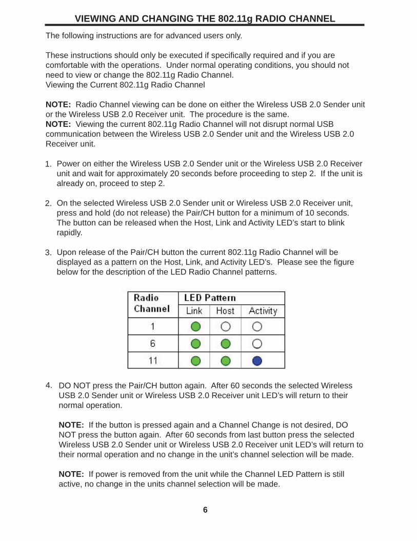
Upon release of the Pair/CH button the current 802.11g Radio Channel will be displayed as a pattern on the Host, Link, and Activity LED’s. Please see the fi gure below for the description of the LED Radio Channel patterns.
4. DO NOT press the Pair/CH button again. After 60 seconds the selected Wireless USB 2.0 Sender unit or Wireless USB 2.0 Receiver unit LED’s will return to their normal operation.
NOTE: If the button is pressed again and a Channel Change is not desired, DO NOT press the button again. After 60 seconds from last button press the selected Wireless USB 2.0 Sender unit or Wireless USB 2.0 Receiver unit LED’s will return to their normal operation and no change in the unit’s channel selection will be made.
NOTE: If power is removed from the unit while the Channel LED Pattern is still active, no change in the units channel selection will be made.
The Wireless USB 2.0 Extender can operate on one of three 802.11g radio channels. Each radio channel broadcasts data in a different frequency band within the 2.4GHz range. The Wireless USB 2.0 Extender can be confi gured to operate on channels: 1, 6, and 11.By selecting a different Radio Channel, you can try to fi nd a channel with minimal radio interference. This can improve signal quality and data rates.
NOTE: When changing the Radio Channel for a “Paired” system, the channel change MUST BE completed on BOTH the Wireless USB 2.0 Sender unit and the Wireless USB 2.0 Receiver unit. The order is non-specifi c.
NOTE: Stop all devices connected to the Wireless USB 2.0 Receiver unit prior to changing the channel on either unit. Changing the Radio Channel will disrupt USB traffi c.
VIEWING CHANGING THE 802.11g RADIO CHANNEL (CONT...)
7
1.
2.
3.
Power on either the Wireless USB 2.0 Sender unit or the Wireless USB 2.0 Receiver unit and wait for approximately 20 seconds before proceeding to step 2. If the unit is already on, proceed to step 2.
On the selected Wireless USB 2.0 Sender unit or Wireless USB 2.0 Receiver unit, press and hold (do not release) the Pair/CH button for a minimum of 10 seconds. The button can be released when the Host, Link and Activity LED’s start to blink rapidly.
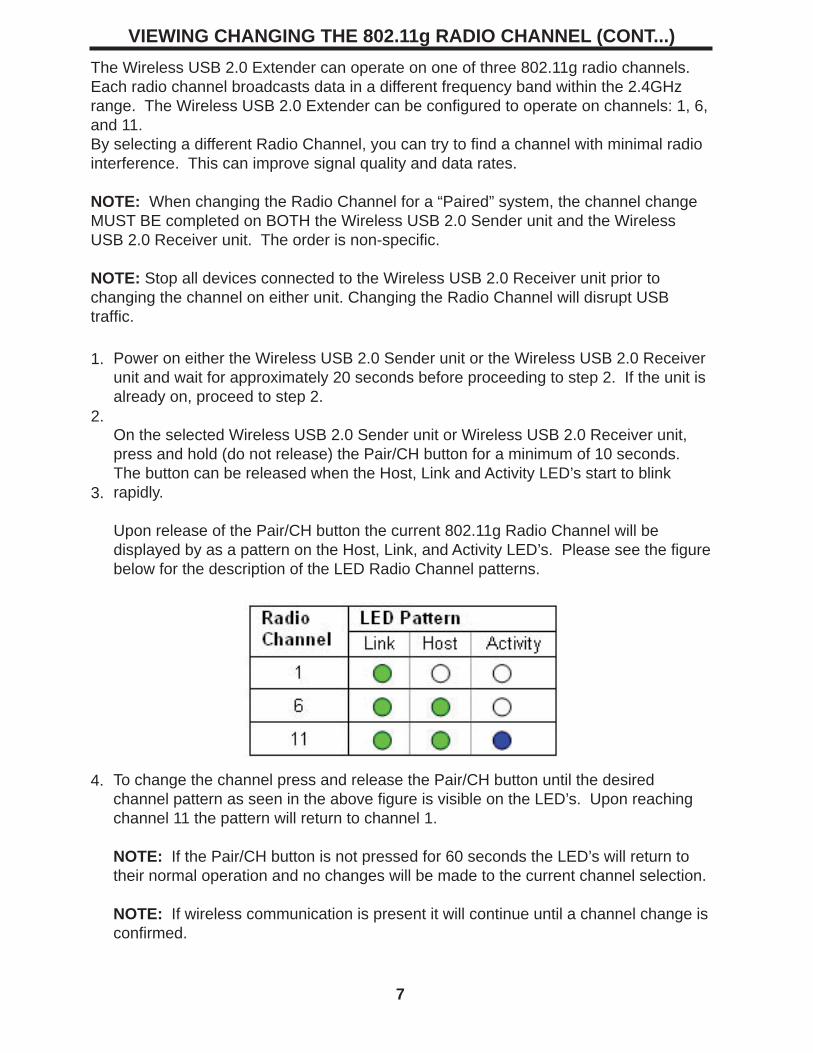
Upon release of the Pair/CH button the current 802.11g Radio Channel will be displayed by as a pattern on the Host, Link, and Activity LED’s. Please see the fi gure below for the description of the LED Radio Channel patterns.
4. To change the channel press and release the Pair/CH button until the desired channel pattern as seen in the above fi gure is visible on the LED’s. Upon reaching channel 11 the pattern will return to channel 1.
NOTE: If the Pair/CH button is not pressed for 60 seconds the LED’s will return to their normal operation and no changes will be made to the current channel selection.
NOTE: If wireless communication is present it will continue until a channel change is confi rmed.
VIEWING CHANGING THE 802.11g RADIO CHANNEL (CONT...)
8
5.
6.
7.
8.
Once the desired 802.11g Radio Channel is displayed, press and hold the Pair/CH button for 10 seconds. The button can be released when the Host, Link and Activity LED’s start to blink rapidly.
NOTE: If the LED’s do not start blinking rapidly within 20 seconds release the button and confi rm that the LED pattern still shows your desired channel pattern. If it does, repeat step 5. If it does not, return to step 4.
Upon release of the Pair/CH button the LED’s will continue to blink for approximately 20 seconds while the Channel Change is stored and the 802.11g radio reboots. Once the blinking stops the Channel Change is complete.
NOTE: DO NOT remove power while LED’s are blinking.
NOTE: If the channel selection on the Wireless USB 2.0 Sender unit and the Wireless USB 2.0 Receiver unit are no longer the same the USB traffi c will now stop. If the channel selection on the Wireless USB 2.0 Sender and Wireless USB 2.0 Receiver are made the same the USB traffi c will begin.
If only one side of the system has been changed repeat steps 1 to 6 for the other side of the system. If channel selection is complete on both sides of the system go to step 8.
Connect a USB cable between the Wireless USB 2.0 Extender and the host PC, and confi rm its operation by checking if it is listed in Device Manager (for Windows installations), or System Profi ler (for Mac OS X installations) under Universal Serial Bus controllers as a “Generic USB Hub”.
The following instructions are for advanced users only.
PAIRING A WIRELESS USB 2.0 SENDER AND RECEIVER
9
These instructions should only be executed if specifi cally required and if you are comfortable with the operations. Under normal operating conditions, you should never need to pair a Wireless USB 2.0 Sender unit and a Wireless USB 2.0 Receiver unit.
Paired units are defi ned as a Wireless USB 2.0 Sender unit and a Wireless USB 2.0 Receiver unit that are aware of each other’s unique address and communicate exclusively.
Pairing is accomplished by infrared (IR) communication through the IR windows on the Wireless USB 2.0 Sender unit and the Wireless USB 2.0 Receiver unit; pairing information is not sent over the 802.11g radios. The IR communication distance is limited to an approximate distance of 20 cm.
NOTE: The Wireless USB 2.0 Extender’s Wireless USB 2.0 Sender unit and Wireless USB 2.0 Receiver unit are shipped paired from the factory.
NOTE: If the Pair/CH button is pressed whether accidentally or purposefully and the Wireless USB 2.0 Sender unit and the Wireless USB 2.0 Receiver unit are not able to communicate via the IR interface no effect in operation will be detected and pairing will not occur.
1.
2.
3.
Place the Wireless USB 2.0 Sender unit and the Wireless USB 2.0 Receiver unit 5 cm apart from each other with their IR windows pointed directly at each other. The IR windows must have a clear and unobstructed view of each other.
Power on both the Wireless USB 2.0 Sender unit and the Wireless USB 2.0 Receiver unit and wait for approximately 20 seconds before proceeding to step 3. If the units are already on, proceed to step 3.
Press the Pair/CH button on either unit for approximately 1 second. Upon release of the button the Host, Link and Activity LED’s on both the Wireless USB 2.0 Sender unit and the Wireless USB 2.0 Receiver unit should begin to blink rapidly.
NOTE: DO NOT remove power while LED’s are blinking.
NOTE: If step 3 is attempted too early after power up, the pairing procedure will not occur. Wait a few seconds longer and retry step 3.
NOTE: If the rapid blinking of the LED’s does not occur, confi rm that the IR windows on the Wireless USB 2.0 Sender unit and the Wireless USB 2.0 Receiver unit are unobstructed, pointed at each other, and are 5 cm apart. Retry pressing the PAIR button. If the LED’s still do not blink upon release of the button unplug both units for at least 10 seconds and return to step 1.
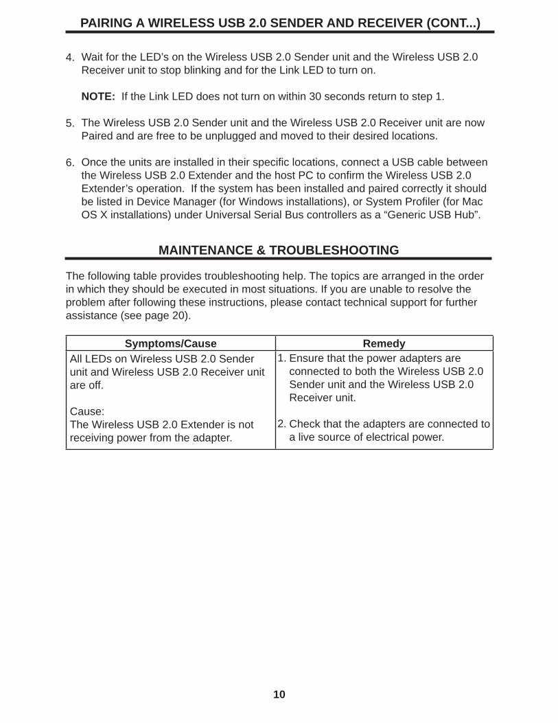
PAIRING A WIRELESS USB 2.0 SENDER AND RECEIVER (CONT...)
10
4.
5.
6.
Wait for the LED’s on the Wireless USB 2.0 Sender unit and the Wireless USB 2.0 Receiver unit to stop blinking and for the Link LED to turn on.
NOTE: If the Link LED does not turn on within 30 seconds return to step 1.
The Wireless USB 2.0 Sender unit and the Wireless USB 2.0 Receiver unit are now Paired and are free to be unplugged and moved to their desired locations.
Once the units are installed in their specifi c locations, connect a USB cable between the Wireless USB 2.0 Extender and the host PC to confi rm the Wireless USB 2.0 Extender’s operation. If the system has been installed and paired correctly it should be listed in Device Manager (for Windows installations), or System Profi ler (for Mac OS X installations) under Universal Serial Bus controllers as a “Generic USB Hub”.
MAINTENANCE & TROUBLESHOOTING
The following table provides troubleshooting help. The topics are arranged in the order in which they should be executed in most situations. If you are unable to resolve the problem after following these instructions, please contact technical support for further assistance (see page 20).
Symptoms/Cause RemedyAll LEDs on Wireless USB 2.0 Sender unit and Wireless USB 2.0 Receiver unit are off.
Cause:The Wireless USB 2.0 Extender is not receiving power from the adapter.
Ensure that the power adapters are connected to both the Wireless USB 2.0 Sender unit and the Wireless USB 2.0 Receiver unit.
Check that the adapters are connected to a live source of electrical power.
1.
2.
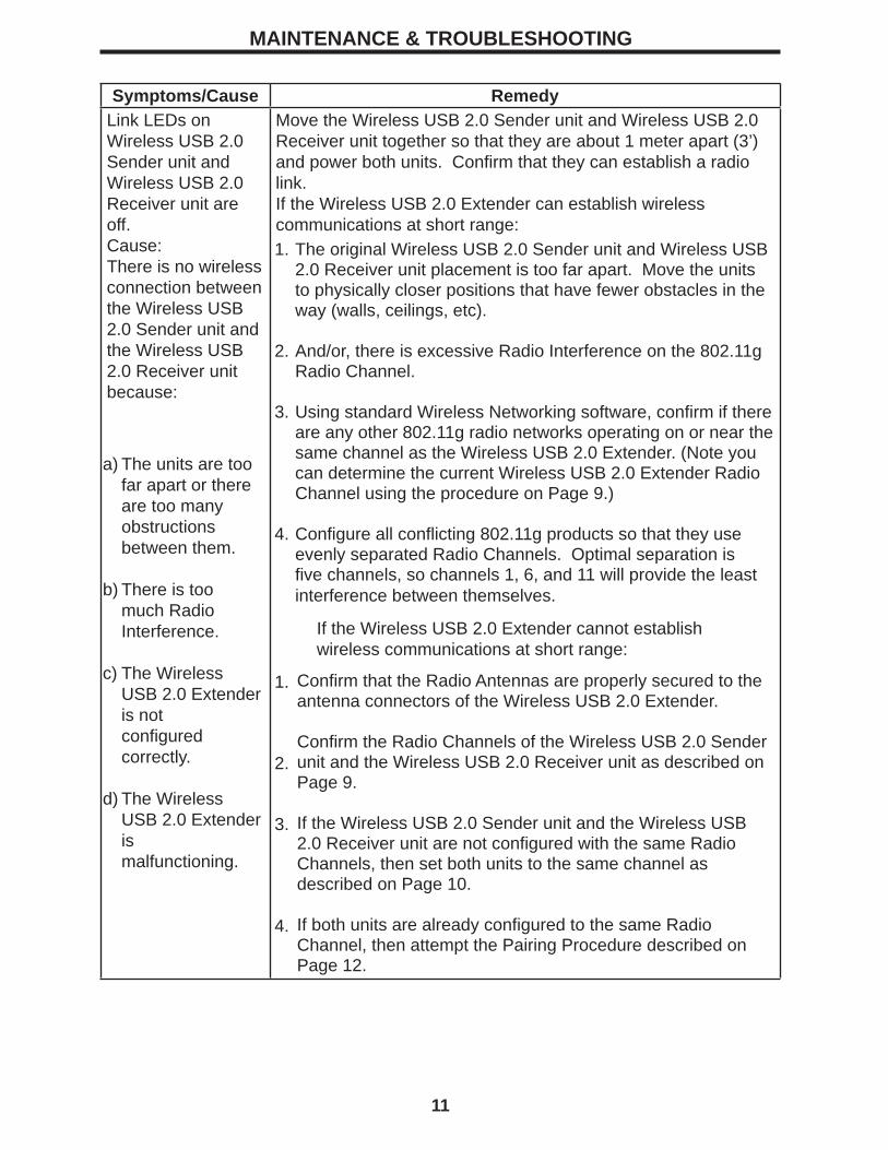
MAINTENANCE & TROUBLESHOOTING
11
Symptoms/Cause RemedyLink LEDs on Wireless USB 2.0 Sender unit and Wireless USB 2.0 Receiver unit are off.Cause: There is no wireless connection between the Wireless USB 2.0 Sender unit and the Wireless USB 2.0 Receiver unit because:
Move the Wireless USB 2.0 Sender unit and Wireless USB 2.0 Receiver unit together so that they are about 1 meter apart (3’) and power both units. Confi rm that they can establish a radio link.If the Wireless USB 2.0 Extender can establish wireless communications at short range:1.
2.
3.
4.
The original Wireless USB 2.0 Sender unit and Wireless USB 2.0 Receiver unit placement is too far apart. Move the units to physically closer positions that have fewer obstacles in the way (walls, ceilings, etc).
And/or, there is excessive Radio Interference on the 802.11g Radio Channel.
Using standard Wireless Networking software, confi rm if there are any other 802.11g radio networks operating on or near the same channel as the Wireless USB 2.0 Extender. (Note you can determine the current Wireless USB 2.0 Extender Radio Channel using the procedure on Page 9.)
Confi gure all confl icting 802.11g products so that they use evenly separated Radio Channels. Optimal separation is fi ve channels, so channels 1, 6, and 11 will provide the least interference between themselves.
If the Wireless USB 2.0 Extender cannot establish wireless communications at short range:
Confi rm that the Radio Antennas are properly secured to the antenna connectors of the Wireless USB 2.0 Extender.
Confi rm the Radio Channels of the Wireless USB 2.0 Sender unit and the Wireless USB 2.0 Receiver unit as described on Page 9.
If the Wireless USB 2.0 Sender unit and the Wireless USB 2.0 Receiver unit are not confi gured with the same Radio Channels, then set both units to the same channel as described on Page 10.
If both units are already confi gured to the same Radio Channel, then attempt the Pairing Procedure described on Page 12.
1.
2.
3.
4.
a)
b)
c)
d)
The units are too far apart or there are too many obstructions between them.
There is too much Radio Interference.
The Wireless USB 2.0 Extender is notconfi gured correctly.
The Wireless USB 2.0 Extender ismalfunctioning.
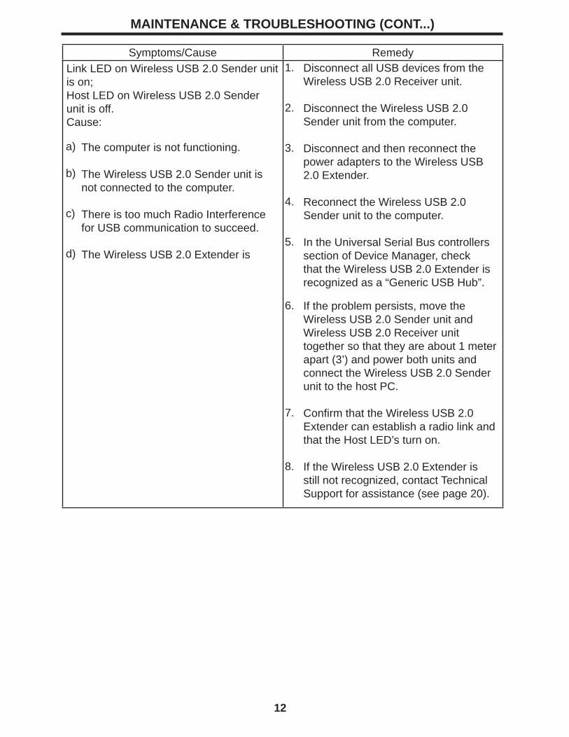
MAINTENANCE & TROUBLESHOOTING (CONT...)
12
Symptoms/Cause RemedyLink LED on Wireless USB 2.0 Sender unit is on;Host LED on Wireless USB 2.0 Sender unit is off.Cause:
1.
2.
3.
4.
5.
6.
7.
8.
Disconnect all USB devices from the Wireless USB 2.0 Receiver unit.
Disconnect the Wireless USB 2.0 Sender unit from the computer.
Disconnect and then reconnect the power adapters to the Wireless USB 2.0 Extender.
Reconnect the Wireless USB 2.0 Sender unit to the computer.
In the Universal Serial Bus controllers section of Device Manager, check that the Wireless USB 2.0 Extender is recognized as a “Generic USB Hub”.
If the problem persists, move the Wireless USB 2.0 Sender unit and Wireless USB 2.0 Receiver unit together so that they are about 1 meter apart (3’) and power both units and connect the Wireless USB 2.0 Sender unit to the host PC.
Confi rm that the Wireless USB 2.0 Extender can establish a radio link and that the Host LED’s turn on.
If the Wireless USB 2.0 Extender is still not recognized, contact Technical Support for assistance (see page 20).
The computer is not functioning.
The Wireless USB 2.0 Sender unit is not connected to the computer.
There is too much Radio Interference for USB communication to succeed.
The Wireless USB 2.0 Extender is
a)
b)
c)
d)
13
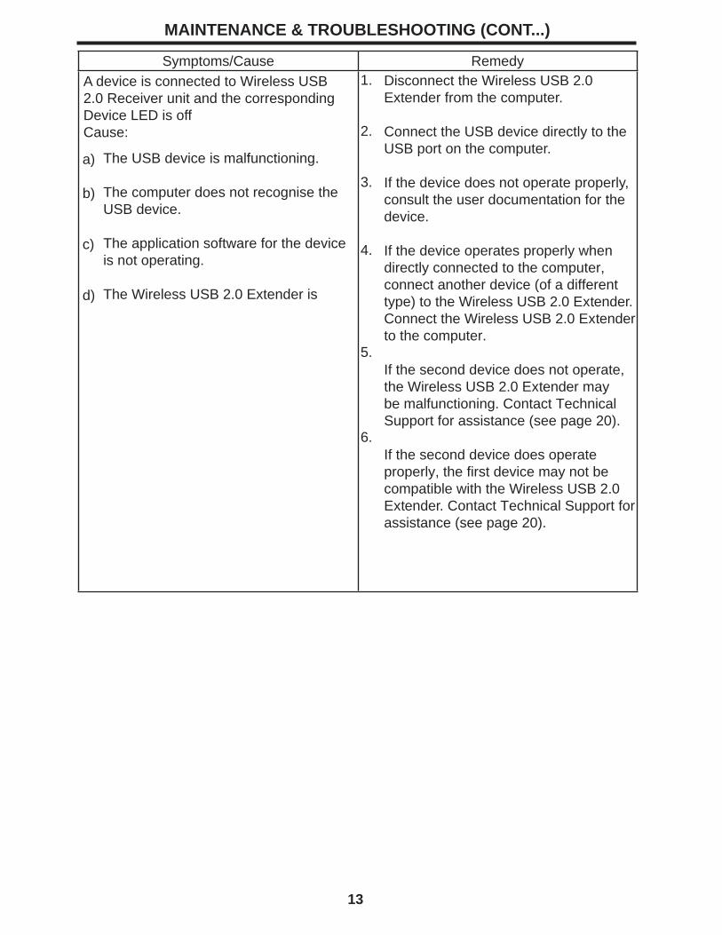
MAINTENANCE & TROUBLESHOOTING (CONT...)
Symptoms/Cause RemedyA device is connected to Wireless USB 2.0 Receiver unit and the corresponding Device LED is offCause:
1.
2.
3.
4.
5.
6.
Disconnect the Wireless USB 2.0 Extender from the computer.
Connect the USB device directly to the USB port on the computer.
If the device does not operate properly, consult the user documentation for the device.
If the device operates properly when directly connected to the computer, connect another device (of a different type) to the Wireless USB 2.0 Extender. Connect the Wireless USB 2.0 Extender to the computer.
If the second device does not operate, the Wireless USB 2.0 Extender may be malfunctioning. Contact Technical Support for assistance (see page 20).
If the second device does operate properly, the fi rst device may not be compatible with the Wireless USB 2.0 Extender. Contact Technical Support for assistance (see page 20).
The USB device is malfunctioning.
The computer does not recognise the USB device.
The application software for the device is not operating.
The Wireless USB 2.0 Extender is
a)
b)
c)
d)
14
MAINTENANCE & TROUBLESHOOTING (CONT...)
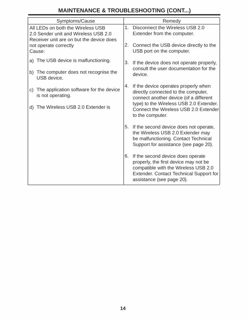
Symptoms/Cause RemedyAll LEDs on both the Wireless USB 2.0 Sender unit and Wireless USB 2.0 Receiver unit are on but the device does not operate correctlyCause:
1.
2.
3.
4.
5.
6.
Disconnect the Wireless USB 2.0 Extender from the computer.
Connect the USB device directly to the USB port on the computer.
If the device does not operate properly, consult the user documentation for the device.
If the device operates properly when directly connected to the computer, connect another device (of a different type) to the Wireless USB 2.0 Extender. Connect the Wireless USB 2.0 Extender to the computer.
If the second device does not operate, the Wireless USB 2.0 Extender may be malfunctioning. Contact Technical Support for assistance (see page 20).
If the second device does operate properly, the fi rst device may not be compatible with the Wireless USB 2.0 Extender. Contact Technical Support for assistance (see page 20).
The USB device is malfunctioning.
The computer does not recognise the USB device.
The application software for the device is not operating.
The Wireless USB 2.0 Extender is
a)
b)
c)
d)
15
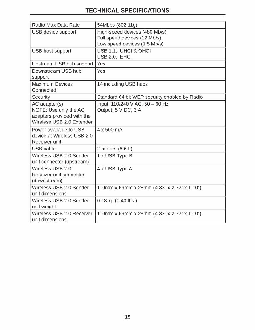
Radio Max Data Rate 54Mbps (802.11g)USB device support High-speed devices (480 Mb/s)
Full speed devices (12 Mb/s)Low speed devices (1.5 Mb/s)
USB host support USB 1.1: UHCI & OHCIUSB 2.0: EHCI
Upstream USB hub support YesDownstream USB hub support
Yes
Maximum Devices Connected
14 including USB hubs
Security Standard 64 bit WEP security enabled by RadioAC adapter(s)NOTE: Use only the AC adapters provided with the Wireless USB 2.0 Extender.
Input: 110/240 V AC, 50 – 60 HzOutput: 5 V DC, 3 A
Power available to USB device at Wireless USB 2.0 Receiver unit
4 x 500 mA
USB cable 2 meters (6.6 ft)Wireless USB 2.0 Sender unit connector (upstream)
1 x USB Type B
Wireless USB 2.0 Receiver unit connector (downstream)
4 x USB Type A
Wireless USB 2.0 Sender unit dimensions
110mm x 69mm x 28mm (4.33” x 2.72” x 1.10”)
Wireless USB 2.0 Sender unit weight
0.18 kg (0.40 lbs.)
Wireless USB 2.0 Receiver unit dimensions
110mm x 69mm x 28mm (4.33” x 2.72” x 1.10”)
TECHNICAL SPECIFICATIONS
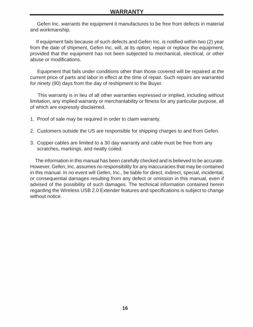
Gefen Inc. warrants the equipment it manufactures to be free from defects in material and workmanship.
If equipment fails because of such defects and Gefen Inc. is notifi ed within two (2) year from the date of shipment, Gefen Inc. will, at its option, repair or replace the equipment, provided that the equipment has not been subjected to mechanical, electrical, or other abuse or modifi cations.
Equipment that fails under conditions other than those covered will be repaired at the current price of parts and labor in effect at the time of repair. Such repairs are warranted for ninety (90) days from the day of reshipment to the Buyer.
This warranty is in lieu of all other warranties expressed or implied, including without limitation, any implied warranty or merchantability or fi tness for any particular purpose, all of which are expressly disclaimed.
1. Proof of sale may be required in order to claim warranty.
2. Customers outside the US are responsible for shipping charges to and from Gefen.
3. Copper cables are limited to a 30 day warranty and cable must be free from any scratches, markings, and neatly coiled.
The information in this manual has been carefully checked and is believed to be accurate. However, Gefen, Inc. assumes no responsibility for any inaccuracies that may be contained in this manual. In no event will Gefen, Inc., be liable for direct, indirect, special, incidental, or consequential damages resulting from any defect or omission in this manual, even if advised of the possibility of such damages. The technical information contained herein regarding the Wireless USB 2.0 Extender features and specifi cations is subject to change without notice.
WARRANTY
16