Embed Size (px)
Citation preview
5
Journal of Environmental Friendly Materials, Vol. 2, No. 2, 2018, 5-14.
Effects of Welding Cycles on Microstructural Characteristics and Mechanical Properties of SAF 2507 Super Duplex Stainless Steel
M. A. Beheshty1,*, E. H. Dehkordi2, K. Zarrin Naghsh1, M. R. B. Marnany3
1 Advanced Materials Research Center, Department of Materials Engineering, Najafabad Branch, Islamic Azad
University, Najafabad, Iran. 2Advanced Materials Research Center, Department of Materials Engineering, Najafabad Branch, Islamic Azad
University, Najafabad, Iran. 3Department of Materials Engineering, Tehran University, Tehran, Iran.
Received: 08 May 2018 – Accepted: 20 June 2018
Abstract
Unique characteristics of SAF 2507 (UNS S32750) super duplex stainless steels alloy such as its high mechanical properties and strong corrosion resistivity behavior led to its widely applications in sea water and other highly corrosive media in oil & gas industries, however, its known that it has also got its own drawbacks particularly the impact and consequences that the number of heating/cooling cycles during its welding or welding repairs may have on its functional characteristics. While international standards/codes are not defining any limitation on weld repairs and/or permitted numbers of weld repairs on duplex stainless steel materials, some owners and clients are limiting the number of permitted repairs to maximum two (just to be in safe side) hence always motivating the question if the number of repairs become more than two, whether and how that could affect the microstructural characteristics and mechanical properties of a welded duplex material. This subject has also never been discussed in any of the earlier investigations. The current proposed article scrutinizing the effect of number of welding repairs on functional characteristics of an SAF 2507 welded plate. 4 samples have been welded by GTAW process using rod ER2594 filler metal with 0 to 3 numbers of repairs on them to evaluate the effect of various numbers of heating/cooling cycles caused by different numbers of repairs on the weldment. Mechanical properties and microstructural characteristics of the samples have been analyzed to observe the excessive presence of any detrimental intermetallic phases and also to see whether any changes in the value of mechanical properties have been occurred or not. It has been concluded that the number of weld repairs (up to 3 times as been examined here and even higher) on welded samples has got no (negligible) negative impacts on the strength of weldments or other mechanical / microstructural characteristics of the weldment, if done properly.
Keywords:Super Duplex Stainless Steel, SAF 2507 SDSS (UNS S32750), Repair Welding, Microstructural Characteristics, Mechanical Properties, Intermetallic phases. 1. Introduction
High mechanical strength and corrosion resistance characteristics demanded mainly in equipment correlated to highly corrosive environments like Desalination plant, Marine Applications, Fuel Gas Scrubbing Equipment, Offshore/Onshore Oil & gas productions etc. explains the reason why Duplex Stainless Steel (DSS) and Super Duplex Stainless Steel (SDSS) are widely been used in industry. High mechanical strength and anti-corrosive characteristics in DSS and SDSS alloys are caused by their two microstructural phases named (Austenite) and (Ferrite) with the effect of their other alloying elements. SDSS Alloy 2507 typically has 25% Chromium, 4% Molybdenum, and 7% Nickel. This results in excellent resistance to chloride pitting and crevice corrosion attack [1,2]; also the duplex microstructure provides 2507 with exceptional resistance to chloride stress corrosion cracking. *Corresponding author Email address: [email protected]
The use of Super Duplex 2507 should be limited to applications below 316°C (600° F). Higher elevated temperature exposure can reduce both the toughness and corrosion resistance of alloy 2507 [1,2].2507 Duplex is highly resistant to uniform corrosion by organic acids such as formic and acetic acid. It is also highly resistant to inorganic acids, especially if they contain chlorides. Alloy 2507 is highly resistant to carbide-related inter-granular corrosion too. Due to the Ferrite portion of the duplex structure of the alloy, it is very resistant to stress corrosion cracking in warm chloride containing environments. The main obstacle in the appliance of SDSSs is unpredictable chemical reactions which occur in the annealing temperature ranging from 300 to 1000°C [1,2]. The consequence of above mentioned harmful reactions is undesirable precipitations of intermetallic phases. Creation of these secondary intermetallic phases in SDSS alloys would result in deviation from standard mechanical characteristics and would deteriorate super duplex stainless steels' corrosion resistance behavior in comparison with their primary conditions.

6
Journal of Environmental Friendly Materials, Vol. 2, No. 2, 2018, 5-14.
The most important deficiencies in SDSS alloys is the possibility of their thermal brittleness causes by number of different thermal cycles mainly through production welding process as a result of formation of secondary phases like Sigma, Chi or R-phase, Nitrides, Carbides and α' (475°C embrittlement) phases at different temperatures [1-4]. For prohibition of occurrence of those mentioned defects during welding, choosing a heat input around 1.5 kj/mm and inter-pass temperature of maximum 100°C is recommended [5]. In the previous investigations, some studies about the effect of welding parameters on mechanical properties, microstructural characteristics and corrosion behavior of welded DSSs and SDSSs samples have been performed [6-18], but the effect of number of repair welding has never been discussed among them. Even international standards/codes are not defining any limitation on weld repairs and/or permitted numbers of weld repairs. Some owners and clients are limiting the number of permitted repairs to maximum two just to be in safe side hence always motivating the question if the number of repairs become more than two, whether and how that could affect the microstructural characteristics and mechanical properties of a welded duplex material. Current paper's goal is to evaluate the effect of the number of weld repairs on microstructural characteristics and mechanical properties of a welded SDSS UNS S32750 (SAF 2507 Alloy) plate. For this purpose, 4 samples have been welded by GTAW process using rod ER2594filler metal and prepared with 0 to 3 numbers of repairs on them in order to evaluate the effect of various numbers of heating/cooling cycles caused by different number of repairs on the weldment (i.e. weld metal, base metal, and HAZ) and to observe the existence of detrimental intermetallic phases formation that would have negative impact on functional characteristic of this
alloy. Repairs have been done using the same rod ER2594 filler metal. 2. Materials and Methods
The base material (BM) studied in this research was a solution-annealed Alloy 2507 plate corresponding to the designation ASTM A240 UNS S32750 with a thickness of 3mm. Mechanical properties and chemical composition of the utilized base material and the utilized 2.4mm diameter ER2594 welding consumables are given in below Table. 1. and Table. 2. The chemical composition comparison between the base material SAF 2507 and ER2594 filler metal indicating that the filler metal has approximately 2.5% more nickel than the base material in order to enhance the austenite formation from solid delta ferrite. The GTAW process has been used for the entire welding i.e. root, filling and final passes using rod ER2594 filler metal. The welding procedure and qualification testing have been performed in accordance with ASME Sec.IX [21].Plates were cut-off in such a way to have a different piece of sections in 200mm in length each. Using a beveling machine, each section beveled with a 35-degree bevel to have 70-degree angle single V-groove butt weld joint with a root gap of 3mm and root face of 1.5mm.X-ray radiography and dye penetrant testing (DPI) was performed to ensure the absence of any cracks in the prepared samples. Pre-weld cleaning was done by gentle grinding. Acetone chemical was also used to remove any type of dirt and oil, Oxide scales, and also to ensure good weld-ability. For fit-up purpose Tack welds were deposited before the start of any welding activity using the same filler metal. 1G flat position of welding has been used with no weaving (i.e. stringing bead).To remove oxides scales during the welding process, manual stainless steel brush was used.
Table. 1. Typical mechanical properties for the plate and welding consumable [19].
Materials Ultimate Tensile Strength, Min.,
Ksi/MPa
Yield Strength, Min., Ksi/MPa
Elongation in 2in or 50mm, Min. %
Hardness, Max. Brinell (HB)/Rockwell C
(HRC) Plate:
ASTM A240 UNS S32750
116/795 80/550 15 310/33
Welding Consumable: rod ER2594
123/850 94/650 28 280/30
Table. 2. Nominal chemical composition (wt %) for the plate and welding consumable [19, 20].
Note: (wt %) in the brackets show the typical chemical composition of the material in the market.
Material Cr Ni Mo C N Mn Si Cu P S W Fe
Plate: ASTM A240 UNS S32750
24-26 (25.0)
6-8 (7.0)
3-5 (4.0)
0.03 Max (0.02)
0.24-0.32 (0.27)
1.2 Max (0.9)
0.8 Max(0.5)
0.5 Max (0.25)
0.035 Max (0.025
0.020 Max (0.015) - Bal.
Welding Consumable rod ER2594
24-27 (25.0)
8-10.5 (9.5)
2.5-4.5 (4.0)
0.03 Max (0.02)
0.2-0.3 (0.25)
2.5 Max (0.8)
1.0 Max(0.4)
0.5 Max (0.01)
0.03 Max (0.02)
0.02 Max (0.01)
0.5 Max (0.05)
Bal.

7
Journal of Environmental Friendly Materials, Vol. 2, No. 2, 2018, 5-14.
Table. 3. The utilized welding parameters and electrical characteristics.
The constant current GTAW process with 99.99% Argon gas for shielding and back purging was employed with DCEN polarity. Filling passes with lower heat input was deposited after the root pass to minimize formation of secondary phases in the root pass of weldments [22]. Three passes of welds were produced using the parameters and electrical characteristics given in Table. 3. The heat input was calculated using Eq. (1) : HI =(60eEI)/(1000S) Eq. (1) where HI is heat input(KJ/mm), E is voltage (V), I is current (A), S is welding travel speed (mm), and e is welding efficiency which was considered as 0.6 for GTAW process [23]. Fig. 1.shows a schematic view of the weld joint configuration and the performed welding sequences. Considering the fact that excessive heating has detrimental effects on mechanical and corrosion properties of SDSS alloys [24], preheating and post weld heat treatment (PWHT) were exempted. The maximum inter-pass temperature applied was 100°C as recommended in API582 [25] to minimize precipitations of the intermetallic phases and was controlled with thermocouples.
Fig. 1. Joint configuration of the welded samples. Four samples were prepared in a similar manner to simulate the number of weld repairs. Samples were tagged with R0 to R3 showing number of repairs on each sample. R0 means no repair and R3 means 3 repairs. 2.1. Microstructural Examinations and Ferrite Measurement Testing For the purpose of general microstructure features of the weld metal examination and HAZs, transverse sections of the welds were examined using metallography examination with the aim of detecting the presence of any intermetallic precipitations.
Special attention was also drawn to detect any cracks in the weldments. The metallographic preparation was conducted by Olympos (Vanox) Optical Microscope as per ASTM E3 [26]. Transverse sections were cut through the welds, followed by grinding and polishing. The etching of BM and WM was carried out using the electro-etch solution of Oxalic Acid+NaOH containing 5gr Oxalic Acid, 18gr NaOH, and 100ml of water, under 8-12 volts and 30-80 seconds at room temperature. Metallography has been supported by SEM and EDS by VEGA3 TESCAN Electron Microscope as perASTM E986for better analysis of microstructure and presence of any intermetallic phases. Additionally, the Ferrite content in deposited weld metal, HAZs and base metal was measured in accordance with ASTM E562 [27] using the point counting technique supported by Fisher FMP30 Ferrite-scope calibrated in accordance with standard procedure specified in AWS A4.2 [28] in order to check whether the distribution of Ferrite and Austenite phases in the microstructure are within the acceptable range as stated in API TR 938C-2011, clause B.6.2.4. [29]. 2.2. Evaluation of Mechanical Properties Transverse tensile tests were performed to identify the region of failure and also to ascertain the strength of weldments. Two transverse tensile samples perpendicular to the welding direction as required in ASME Sec IX, QW-451 [21], were extracted and tested as per ASTM standard A370 [30] at room temperature. Tensile tests were done using a universal tensile testing machine (GEOTEC AL-7000-LA20/60 & TCS-2000) in such a way that the entire weld region (i.e. the WM with its either sides of HAZs and BMs) was in the gauge section. Microhardness was measured across the weld metal and HAZ as shown in Fig. 2.using Vickers hardness tester Wolpert V-Tester2, under 10N load (HV10) on the prepared microstructure samples to get an idea about weldments properties. The microhardness test was performed in accordance with ASTM E92 [31]. Fig. 2. shows the location of hardness test points measurement across the weld metal, base material and HAZs on the face and root section of the weldment. Three Charpy V-notch impact tests samples of10mm × 3mm were prepared and tested at -46°C temperature to evaluate the toughness of weld metal and heat affected zones (HAZs) and detection of detrimental intermetallic phase
Heat Input (HI),
(KJ/mm)
Travel Speed, (mm/s)
Voltage, V Current, A Pass Polarity Electrode diameter
Filler Metal type and AWS Classification
Back purging gas flow
rate
Shielding gas flow
rate
Shielding & back purging
gas 0.74 70 10-12 110-130 Root
DCEN 2.4mm ER2594, AWS A5.9
5 L/min 8 L/min Pure argon (99.99%) 0.58 90 10-12 100-120
Filling and Cap
8
Journal of Environmental Friendly Materials, Vol. 2, No. 2, 2018, 5-14.
precipitation in duplex stainless steel. The notch preparation and machining were conducted as per ASTM A370 [30].
Fig. 2. Cross sectional hardness measuring points.
Test samples have been taken from mid-section of the welded specimen at weld metal center (CW), and fusion line (FL) plus 2mm (HAZs).
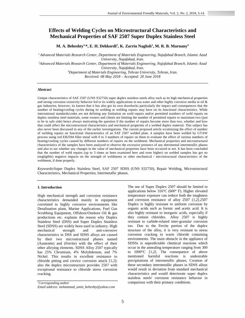
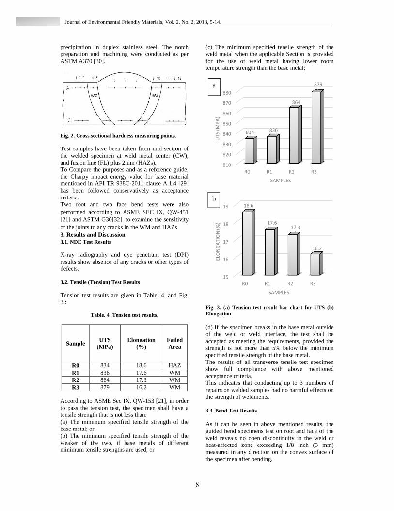
To Compare the purposes and as a reference guide, the Charpy impact energy value for base material mentioned in API TR 938C-2011 clause A.1.4 [29] has been followed conservatively as acceptance criteria. Two root and two face bend tests were also performed according to ASME SEC IX, QW-451 [21] and ASTM G30[32] to examine the sensitivity of the joints to any cracks in the WM and HAZs 3. Results and Discussion 3.1. NDE Test Results X-ray radiography and dye penetrant test (DPI) results show absence of any cracks or other types of defects. 3.2. Tensile (Tension) Test Results Tension test results are given in Table. 4. and Fig. 3.:
Table. 4. Tension test results.
Sample UTS
(MPa) Elongation
(%) Failed Area
R0 834 18.6 HAZ R1 836 17.6 WM R2 864 17.3 WM R3 879 16.2 WM
According to ASME Sec IX, QW-153 [21], in order to pass the tension test, the specimen shall have a tensile strength that is not less than: (a) The minimum specified tensile strength of the base metal; or (b) The minimum specified tensile strength of the weaker of the two, if base metals of different minimum tensile strengths are used; or
(c) The minimum specified tensile strength of the weld metal when the applicable Section is provided for the use of weld metal having lower room temperature strength than the base metal;
Fig. 3. (a) Tension test result bar chart for UTS (b) Elongation. (d) If the specimen breaks in the base metal outside of the weld or weld interface, the test shall be accepted as meeting the requirements, provided the strength is not more than 5% below the minimum specified tensile strength of the base metal. The results of all transverse tensile test specimen show full compliance with above mentioned acceptance criteria. This indicates that conducting up to 3 numbers of repairs on welded samples had no harmful effects on the strength of weldments. 3.3. Bend Test Results As it can be seen in above mentioned results, the guided bend specimens test on root and face of the weld reveals no open discontinuity in the weld or heat-affected zone exceeding 1/8 inch (3 mm) measured in any direction on the convex surface of the specimen after bending.
810
820
830
840
850
860
870
880
R0 R1 R2 R3
834 836
864
879
UT
S (
MP
A)
SAMPLES
a
15
16
17
18
19
R0 R1 R2 R3
18.6
17.617.3
16.2
ELO
NG
AT
ION
(%
)
SAMPLES
b

9
Journal of Environmental Friendly Materials, Vol. 2, No. 2, 2018, 5-14.
Bend test results are given in Table. 5.:
Table. 5. Bend test results.
Sample Number of repair Results
R0 Zero No discontinuities
R1 1 No discontinuities
R2 2 No discontinuities
R3 3 No discontinuities
3.4. Charpy Impact Test Results The results of Charpy impact testing has been evaluated in accordance with ASTM A923 [34] Test Method B as described in API TR 938C-2011 clause A.1.4. [29] The test results are as reported in Table 6. ASTM A923 test method B has been followed because it is a method for detection of detrimental intermetallic phase precipitation in duplex stainless steels. Low impact energy results value in comparison with the code acceptable value would stipulate the presence of higher amount of intermetallic phase precipitation, leading to brittle fracture. According to API TR 938C-2011 clause A.1.4 [29], the acceptance criteria for Test Method B for a 25% Cr duplex stainless steel base material grades UNS S32750, shall include testing at –46°C (−50°F), with a test results as 70J average, 65J minimum (52 ft-lb average, 48 ft-lb minimum) for base metal for a full size 10mm x 10mm test specimen. Similar acceptance criteria have been considered for evaluation of weld metal test results and HAZ. Considering the fact that our test specimen here were sub-sized sample of 10mm x 3mm, therefore the standard energy values in such cases shall need to be multiplied by the ratio of the actual specimen width to that of a full-size specimen (i.e. 0.3 in this case) to obtain the acceptable test results energy value as described in ASME Section VIII, Div.1, UG-84 [35]. According to the same clause of this standard, if the largest obtainable Charpy V-notch specimen had a width along the notch of at least 80% of the material nominal thickness (which is applicable to our case), then temperature reduction for Charpy impact test won’t be needed hence tested at -46°C. Accordingly, acceptable energy results value for sub-size 10mm x
3mm test specimen shall be at least 21J average, 19.5J minimum. All test results are found to be accordingly acceptable and meeting the code requirements, which shows conducting up to 3 number of repairs on welded samples had no harmful effects on the toughness of weldments which proves that the amount of precipitated intermetallic phases even after 3 cycles of repairs were not excessive. The lateral expansion measurements have been reported for information. The calculation of lateral expansion has been performed by Wiesner [36]. The acceptance criteria for lateral expansion have been considered the one stated in ASME B31.3 [37] clause 323.3.5 for highly alloyed steels (i.e. >0.38mm for a 10mm x 10mm sample). Similar acceptance criteria (i.e. >0.38mm) have also been referred in NORSOK M601 [38].
Table. 6. Charpy impact test results energy values.
Sample Notch
Location
Test Temp. (°C)
Impact Values
(J)
Lateral Expansion
(mm)
R0 Weld Metal -46°C 35 0.4300
R1 Weld Metal -46°C 36 0.4400
R2 Weld Metal -46°C 33 0.4000
R3 Weld Metal -46°C 40 0.4900
R0 Fusion
Line+2mm (HAZ)
-46°C 42 0.5100
R1 Fusion
Line+2mm (HAZ)
-46°C 46 0.5600
R2 Fusion
Line+2mm (HAZ)
-46°C 48 0.5900
R3 Fusion
Line+2mm (HAZ)
-46°C 44 0.5400

10
Journal of Environmental Friendly Materials, Vol. 2, No. 2, 2018, 5-14.
Referencing this acceptance criterion for lateral expansion of a full size sample, the obtained results would be acceptable for sub size samples. The cross sectional area for impact test by SEM for all test samples shows ductile surface with no sign of embrittlement. Fig. 4. shows SEM of Charpy impact test fracture cross sectional area for samples with 2 and 3 repairs.
Fig. 4. SEM of the charpy impact test fracture cross sectional area. (a) & (b) is related to a sample after 2 repairs (R2) and (c) & (d) is related to a sample after 3 repairs (R3).
3.5. Microhardness Test Results The microhardness profile of the weld cap region in Fig. 5. and weld root region in Fig. 6. shows that the measured hardness values in the HAZ area for all samples are compatible with those found for the base material and weld metal. The base material average hardness values were found to be around 340 HV10 for all samples (i.e. the main welded sample and those 3 repaired samples).
Fig. 5. Microhardness profile of the weld cap region for different samples.
Fig. 6. Microhardness profile of the weld root region for different samples. None of the results are found to be more than 350 HV10 which meets API TR 938C-2011, clause B.6.4 [29] requirements for super duplex stainless steel grades. The hardness values on heat affected zone for all samples are slightly higher than the hardness values on base metal and weld metal (approximately 345 HV10 as an average) which is anticipated to be due to microstructural changes and possibility of intermetallic phases precipitation in HAZ as a result of repairs operations, however, as none of the results in any area are beyond the code
b
d
a
c

11
Journal of Environmental Friendly Materials, Vol. 2, No. 2, 2018, 5-14.
requirements acceptance criteria (i.e. 350 HV10), therefore it can be concluded that the amount of precipitated intermetallic phases in weld metal and HAZ even after 3 repairs are within acceptable range and are not excessive. 3.5. Microstructural Examinations and Ferrite Measurement Testing Results Microstructural examination of base material, weld metal and HAZ of test samples with no repair and 1 to 3 repairs have been performed and all results showed a mixed Ferrite-Austenite phase in all area as shown in Fig. 7. ,Fig. 8. and Fig. 9.Phase with light color is Austenite and phase with darker color are Ferrite..
Fig. 7. Optical microscopic examination of base material microstructure . Evaluation of weld metal and HAZ microstructural examination had shown a mixture of Ferrite, primary Austenite, and traces of secondary Austenite phases. Those widmanstatten Austenite phase formations are related to the way the weld has cooled down. General industry practice is to utilize an identical welding consumable as production for the purpose of repair using similar welding parameters as production, therefore it is anticipated to not see much difference in microstructure of weld metal in a sample with no repairs and samples with 1 to 3 repairs as can be seen in Fig. 8. (a) to (d).Surrounded area of the overlapped repairs had shown slight increase in the amount of Ferrite phase in it but still found to be within the mentioned acceptable limits in API TR 938C-2011 clause B.6.2.3 [29].A higher amount of Ferrite phase in overlapped surrounded area was expected because the old layer acted as HAZ for the newly deposited weld metal layer. In general, the HAZ, which is a mixing region of the weld, is considered to be the most susceptible area of any weld and known to be more susceptible to corrosion due to possibility of precipitation of more detrimental intermetallic phases in that area. As can be seen in Fig. 8. and Fig. 9., the distribution of Ferrite and Austenite phase are approximately equal within the microstructure of both weld metal and HAZ with slightly higher amount of Ferrite phase detection
which is acceptable for a Superduplex microstructure as stated in API TR 938C-2011 clause B.6.2.3 [29].Phases distributions and proportions was expected to fall within the codes acceptable limits as the utilized ER2594 filler metals had approximately 2.5% more nickel than the base material which enhances the Austenite formation from solid delta Ferrite preventing excessive Ferrite phase formation in the microstructure.
Fig. 8. Optical microscopic examination of weld metal microstructure. (a), (b), (c), (d) is referred to the samples with 0 to 3 repairs respectively.
a
b
c
d

12
Journal of Environmental Friendly Materials, Vol. 2, No. 2, 2018, 5-14.
Fig. 9. Optical microscopic examination of HAZ microstructure for a sample with 3 repairs. EDS/SEM of HAZ area of the weld with different number of repairs had shown no continuous and excessive precipitation of detrimental intermetallic phase in it however, as it was expected the amount of intermetallic phases formation (like Carbide/Nitride, Sigma and Chi phases and in particular Sigma phase) in HAZ area were increased with escalating the number of repairs as can be seen in Fig. 10. and Fig.11.
Fig. 10. EDS/SEM analysis of a sigma phase observed in HAZ area of a sample with 2 repairs.
The intermetallic precipitated phases, as EDS analysis shows, has got high concentration of chromium in it proving chromium depletion in its surrounded areas making those areas more susceptible to corrosion. Considering the fact that the results of all mechanical tests described in section 3.2 to 3.5 are all within the codes acceptable limits, it proves that the phase distributions and proportions as well as the amount of intermetallic phases formation on weld metal and HAZ after 3 cycle of repairs shall be acceptable and that had no (negligible) detrimental effects on material properties.
Fig. 11. EDS/SEM analysis of a sigma phase observed in HAZ area of a sample with 3 repairs.
4. Conclusions 1. The mechanical test result shows that conducting up to 3 numbers of repairs on welded samples had no harmful effects on the strength of weldments. 2. The hardness values on heat affected zone for all samples are slightly higher than the hardness values on base metal and weld which is anticipated to be due to microstructural changes and possibility of intermetallic phases precipitation in HAZ as a result of repairs operations. 3. The Charpy impact test energy results value for all tested samples on weld metal and HAZ are found to be acceptable and shows conducting up to 3 numbers of repairs on welded samples had no harmful effects on the toughness of weldments.

13
Journal of Environmental Friendly Materials, Vol. 2, No. 2, 2018, 5-14.
4. TheEDS/SEM of HAZ area of the weld with different numbers of repairs had shown no continuous precipitation of detrimental intermetallic phase in it. 5.Accordingly, based on the current research, it can be concluded that the number of weld repairs (up to 3 times as been examined here and even higher) on SDSS AISI 2507 Alloy plate welded samples has got no (negligible) detrimental impacts on the strength of weldments or other mechanical / microstructural characteristics of the weldment. References [1] M. I. M. Bassiouni, "Evaluation of the microstructure and localized corrosion behavior of AISI 2507 super duplex stainless steel welds ", Ph.D. thesis, School of civil, environmental & chemical engineering, RMIT University, March 2012. [2] J.Charles Super duplex stainless steels: Structure and properties. Proc. Duplex Stainless Steels 91. Les Editions de Physique, F-91944 Les Cedex, (1991) 23-48. France, [3] M. Al-Rabie, "Observation of stress corrosion cracking behavior in super duplex stainless", Ph.D. thesis, School of Materials, University of Manchester, 2011. [4] U. Obi, "Effect of aging on phase evolution, mechanical and corrosion properties of a high tungsten super duplex stainless steel", Ph.D. thesis, School of Engineering, University of Aberdeen, February 2015. [5] API Technical Report 938-C. 2005. Use of Duplex Stainless Steels in the Oil Refining Industry:American Petroleum Institute: First Edition. Washington, D.C. [6] K. D.Ramkumar, G. Thiruvengatam, S. P. Sudharsan, D. Mishra, N. Arivazhagan and R. Sridhar, Mat. Des., 60, 2014, 125. [7] K.D.Ramkumar, D. Mishra, G. Thiruvengatam, S.P. Sudharsan, T. Harsha Mohan, V. Saxena, R. Pandey and N. Arivazhagan, Bull. Mater. Sci, 38(4), 2015,837. [8] Hua Huang, Jing-Hui Jin, Zhong-Ping Ding, Springer Int. Publ.Switzerland, 2015,493. [9] Villalobos, Albiter, Maldonado, RevistaMatéria, 14(3), 2009,1061. [10] K. D. Ramkumar, D. Mishra, B. Ganesh Raj, M.K. Vignesh, G. Thiruvengatam, SP. Sudharshan, N. Arivazhagan, N. Sivashanmugam and A. M. Rabel, Mater. Des. , 2014. [11] V. A. Hosseini, M. Asunción Valiente Bermejo, J. Gårdstam, K. Hurtig, L.Karlsson, Int. Inst. Welding, 2016. [12] K. D.Ramkumar, A. Singh, S. Raghuvanshi, A. Bajpai, T. Solanki, M. Arivarasu, N. Arivazhagan and S. Narayanan, J. Manuf. Processes, 2015.
[13] N.Pettersson, Rachel F.A. Pettersson and S. Wessman, The Minerals, Met. Mater. Society ASM Int., 2014. [14] M. Rahmani, A. Eghlimi and M.Shamanian, J. of mater. Eng. and perform., 2014. [15] N.Llorca-Isern, H. López-Luque, I. López-Jiménez andM. V. Biezma, Mater. Character. , (112), 2015,20. [16] H. Huang, Jing-Hui Jin and Zhong-Ping Ding, Springer int. publ. Switzerland, 2015. [17] P. Paulraj, R. Garg, Manuf. Rev.,02(29) 2015. [18] G. C. de Souza, A. L. da Silva, S. S. M. Tavares, J. M. Pardal, M. L. R. Ferreira and I. CardoteFilho, Welding Int., 30(6) 2016, 432. [19] Standard Specification for Chromium and Chromium-Nickel Stainless Steel Plate, Sheet, and Strip for Pressure Vessels and for General Applications, Designation: A 240/A 240M – 04a, ASTM International. [20] AWS A5.9/A5.9M, Specification for Bare Stainless Steel Welding Electrodes and Rods. [21] ASME SEC IX, Welding Procedure and performance qualification, American Society of Mechanical Engineers, 2017. [22] J.O. Nilsson, L. Karlsson, and J. O. Andersson, Steel Weld Metal, Mater. Sci. Technol., 11(3), 1995, 276. [23] A. Eghlimi, M. Shamanian, and K. Raeissi, J. Mater. Eng. Perform, 22(12), 2013, 3657. [24] M. Martins, S.M. Rossitti, M. Ritoni, and L.C. Casteletti, Mater. Charact, 58(10), 2007, 909. [25] API 582 Ed. 3, Welding Guidelines for the Chemical, Oil, And Gas Industries from SAI Global. [26] ASTM E3 – 11, Standard Guide for Preparation of Metallographic Specimens [27] ASTM E562 – 11, Standard Test Method for Determining Volume Fraction by Systematic Manual Point Count. [28] ANSI/AWS A4. 2M/A4. 2-1997, Standard Procedures for Calibrating Magnetic Instruments to Measure the Delta Ferrite Content of Austenitic andDuplex Ferritic Austenitic Stainless Steel Weld Metal. [29] API TECHNICAL REPORT 938-C, Use of Duplex Stainless Steels in the Oil Refining Industry, Second Edition, April 2011 [30] ASTM A370 – 17, Standard Test Methods and Definitions for Mechanical Testing of Steel Products. [31] ASTM E92 – 17, Standard Test Methods for Vickers Hardness and Knoop Hardness of Metallic Materials. [32] ASTM G30 – 97(2016), Standard Practice for Making and Using U-Bend Stress-Corrosion Test Specimens. [33] ISO 7539-10:2013, Corrosion of metals and alloys, Stress corrosion testing, Part 10: Reverse U-bend method.

14
Journal of Environmental Friendly Materials, Vol. 2, No. 2, 2018, 5-14.
[34] ASTM A923 – 14, Standard Test Methods for Detecting Detrimental Intermetallic Phase in Duplex Austenitic/Ferritic Stainless Steels. [35] ASME Boiler and Pressure Vessel Code, Section VIII, Rules for Construction of Pressure Vessels, Div.1, UG-84, American Society of Mechanical Engineers, 2017. [36] C. S. Wiesner, Duplex Stainless Steels 97, Proceedings of the 5th World Conference, Maastricht, The Netherlands, 21-23 October 1997, Zutphen, KCI Publishing, 1997, Book 2, pp.979-990. [37] ASME B31.3, Process Piping Code, American Society of Mechanical Engineers, 2016. [38] NORSOK M-601:2016 Welding and Inspection of piping.