Embed Size (px)
Citation preview
International Journal of Computational Engineering Research||Vol, 03||Issue, 6||
www.ijceronline.com ||June ||2013|| Page 45
Effects of Earthquake Loads on Existing School Buildings In
Sudan
M.A. Ismaeil1, A.E. Hassaballa
2
1 King Khalid University, KSA. On Leave from Sudan University of Science and Technology, Khartoum, Sudan, 2Alhosn University, UAE. On Leave from Cairo University, Giza, Egypt, 3Jazan University, KSA. On Leave from
Sudan University of Science and Technology, Khartoum, Sudan,
I. INTRODUCTION An earthquake is the vibration of the earth’s surface that follows a sudden release of energy in the crust. During an earthquake, the ground surface moves in all directions. The most damaging effects on buildings
are caused by lateral movements which disturb the stability of the structure, causing it to topple or to collapse
sideways. Since buildings are normally constructed to resist gravity, many traditional systems of construction
are not inherently resistant to horizontal forces. Thus design for earthquakes consists largely of solving the
problem of building vibrations. Sudan is not free from earthquakes. It has experienced many earthquakes during
the recent history [1], and the previous studies on this field demonstrated this argument [1]. Schools play a vital
role in the community. Schools play a vital role in the community. They are not only the places where students
learn and teachers teach; they are also used for social gatherings, theatre and sports. In addition, school
buildings play an important role in responding to and recovering from natural disasters. In the event of an
earthquake, hurricane or flood, schools can serve as emergency shelters and, as such, can be used to house, feed
and care for the local population. This research in an attempt to study the effect of seismic loading on school buildings in Sudan.
II. FIRST CASE STUDY 2.1 Description of the school building
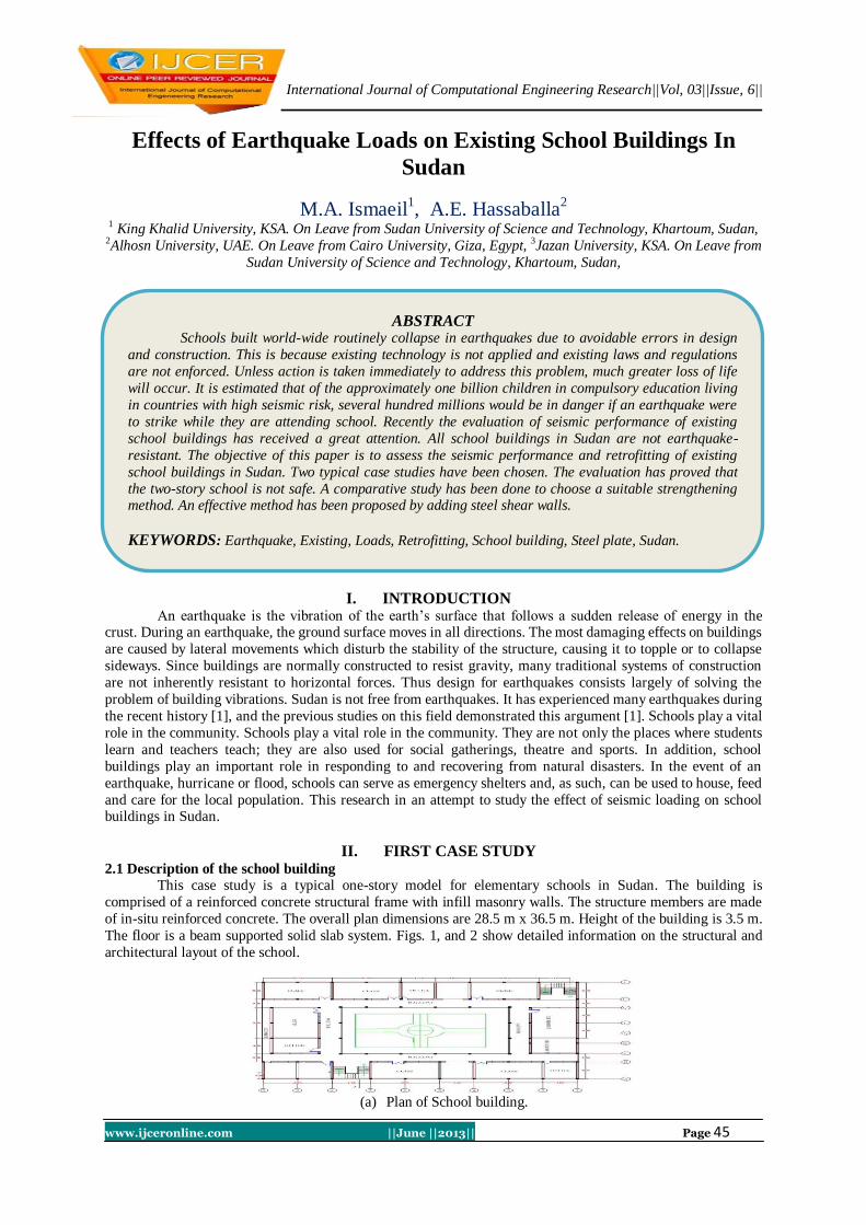
This case study is a typical one-story model for elementary schools in Sudan. The building is
comprised of a reinforced concrete structural frame with infill masonry walls. The structure members are made
of in-situ reinforced concrete. The overall plan dimensions are 28.5 m x 36.5 m. Height of the building is 3.5 m.
The floor is a beam supported solid slab system. Figs. 1, and 2 show detailed information on the structural and
architectural layout of the school.
(a) Plan of School building.
ABSTRACT Schools built world-wide routinely collapse in earthquakes due to avoidable errors in design
and construction. This is because existing technology is not applied and existing laws and regulations
are not enforced. Unless action is taken immediately to address this problem, much greater loss of life
will occur. It is estimated that of the approximately one billion children in compulsory education living
in countries with high seismic risk, several hundred millions would be in danger if an earthquake were
to strike while they are attending school. Recently the evaluation of seismic performance of existing
school buildings has received a great attention. All school buildings in Sudan are not earthquake-
resistant. The objective of this paper is to assess the seismic performance and retrofitting of existing
school buildings in Sudan. Two typical case studies have been chosen. The evaluation has proved that
the two-story school is not safe. A comparative study has been done to choose a suitable strengthening method. An effective method has been proposed by adding steel shear walls.
KEYWORDS: Earthquake, Existing, Loads, Retrofitting, School building, Steel plate, Sudan.
Effects Of Earthquake Loads On Existing...
www.ijceronline.com ||June ||2013|| Page 46
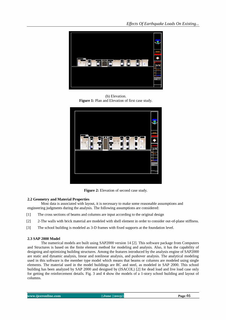
(b) Elevation.
Figure 1: Plan and Elevation of first case study.
Figure 2: Elevation of second case study.
2.2 Geometry and Material Properties
Most data is associated with layout, it is necessary to make some reasonable assumptions and
engineering judgments during the analysis. The following assumptions are considered:
[1] The cross sections of beams and columns are input according to the original design
[2] 2-The walls with brick material are modeled with shell element in order to consider out-of-plane stiffness.
[3] The school building is modeled as 3-D frames with fixed supports at the foundation level.
2.3 SAP 2000 Model The numerical models are built using SAP2000 version 14 [2]. This software package from Computers
and Structures is based on the finite element method for modeling and analysis. Also, it has the capability of
designing and optimizing building structures. Among the features introduced by the analysis engine of SAP2000
are static and dynamic analysis, linear and nonlinear analysis, and pushover analysis. The analytical modeling
used in this software is the member type model which means that beams or columns are modeled using single
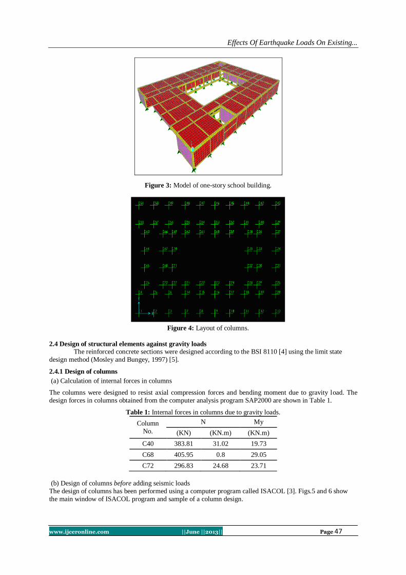
elements. The material used in the model buildings are RC and steel, as modeled in SAP 2000. This school
building has been analyzed by SAP 2000 and designed by (ISACOL) [2] for dead load and live load case only
for getting the reinforcement details. Fig. 3 and 4 show the models of a 1-story school building and layout of
columns.
Effects Of Earthquake Loads On Existing...
www.ijceronline.com ||June ||2013|| Page 47
Figure 3: Model of one-story school building.
Figure 4: Layout of columns.
2.4 Design of structural elements against gravity loads
The reinforced concrete sections were designed according to the BSI 8110 [4] using the limit state
design method (Mosley and Bungey, 1997) [5].
2.4.1 Design of columns
(a) Calculation of internal forces in columns
The columns were designed to resist axial compression forces and bending moment due to gravity load. The
design forces in columns obtained from the computer analysis program SAP2000 are shown in Table 1.
Table 1: Internal forces in columns due to gravity loads.
Column
No.
N My
(KN) (KN.m) (KN.m)
C40 383.81 31.02 19.73
C68 405.95 0.8 29.05
C72 296.83 24.68 23.71
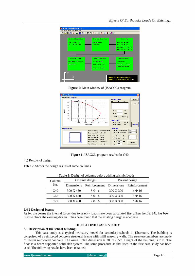
(b) Design of columns before adding seismic loads
The design of columns has been performed using a computer program called ISACOL [3]. Figs.5 and 6 show
the main window of ISACOL program and sample of a column design.
Effects Of Earthquake Loads On Existing...
www.ijceronline.com ||June ||2013|| Page 48
Figure 5: Main window of (ISACOL) program.
Figure 6: ISACOL program results for C40.
(c) Results of design
Table 2. Shows the design results of some columns
Table 2: Design of columns before adding seismic Loads
Column
No.
Original design Present design
Dimensions Reinforcement Dimensions Reinforcement
C40 300 X 450 8 Φ 16 300 X 300 6 Φ 16
C68 300 X 450 8 Φ 16 300 X 300 6 Φ 16
C72 300 X 450 8 Φ 16 300 X 300 6 Φ 16
2.4.2 Design of beams
As for the beams the internal forces due to gravity loads have been calculated first .Then the BSI [4], has been
used to check the existing design. It has been found that the existing design is adequate.
III. SECOND CASE STUDY 3.1 Description of the school building
This case study is a typical two-story model for secondary schools in Khartoum. The building is comprised of a reinforced concrete structural frame with infill masonry walls. The structure members are made
of in-situ reinforced concrete .The overall plan dimension is 28.5x36.5m. Height of the building is 7 m .The
floor is a beam supported solid slab system. The same procedure as that used in the first case study has been
used. The following results have been obtained:
Effects Of Earthquake Loads On Existing...
www.ijceronline.com ||June ||2013|| Page 49
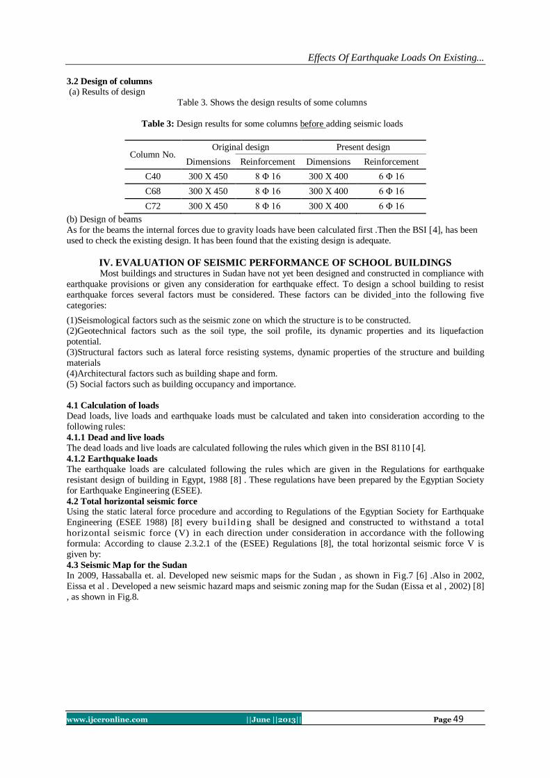
3.2 Design of columns
(a) Results of design
Table 3. Shows the design results of some columns
Table 3: Design results for some columns before adding seismic loads
Column No. Original design Present design
Dimensions Reinforcement Dimensions Reinforcement
C40 300 X 450 8 Φ 16 300 X 400 6 Φ 16
C68 300 X 450 8 Φ 16 300 X 400 6 Φ 16
C72 300 X 450 8 Φ 16 300 X 400 6 Φ 16
(b) Design of beams
As for the beams the internal forces due to gravity loads have been calculated first .Then the BSI [4], has been
used to check the existing design. It has been found that the existing design is adequate.
IV. EVALUATION OF SEISMIC PERFORMANCE OF SCHOOL BUILDINGS Most buildings and structures in Sudan have not yet been designed and constructed in compliance with
earthquake provisions or given any consideration for earthquake effect. To design a school building to resist
earthquake forces several factors must be considered. These factors can be divided into the following five
categories:
(1)Seismological factors such as the seismic zone on which the structure is to be constructed.
(2)Geotechnical factors such as the soil type, the soil profile, its dynamic properties and its liquefaction
potential.
(3)Structural factors such as lateral force resisting systems, dynamic properties of the structure and building
materials
(4)Architectural factors such as building shape and form.
(5) Social factors such as building occupancy and importance.
4.1 Calculation of loads
Dead loads, live loads and earthquake loads must be calculated and taken into consideration according to the
following rules:
4.1.1 Dead and live loads
The dead loads and live loads are calculated following the rules which given in the BSI 8110 [4].
4.1.2 Earthquake loads
The earthquake loads are calculated following the rules which are given in the Regulations for earthquake
resistant design of building in Egypt, 1988 [8] . These regulations have been prepared by the Egyptian Society
for Earthquake Engineering (ESEE).
4.2 Total horizontal seismic force Using the static lateral force procedure and according to Regulations of the Egyptian Society for Earthquake
Engineering (ESEE 1988) [8] every bui ld ing shall be designed and constructed to withstand a total
horizontal seismic force (V) in each direction under consideration in accordance with the following
formula: According to clause 2.3.2.1 of the (ESEE) Regulations [8], the total horizontal seismic force V is
given by:
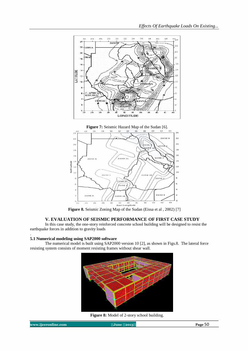
4.3 Seismic Map for the Sudan
In 2009, Hassaballa et. al. Developed new seismic maps for the Sudan , as shown in Fig.7 [6] .Also in 2002,
Eissa et al . Developed a new seismic hazard maps and seismic zoning map for the Sudan (Eissa et al , 2002) [8]
, as shown in Fig.8.
Effects Of Earthquake Loads On Existing...
www.ijceronline.com ||June ||2013|| Page 50
Figure 7: Seismic Hazard Map of the Sudan [6].
Figure 8. Seismic Zoning Map of the Sudan (Eissa et al , 2002) [7]
V. EVALUATION OF SEISMIC PERFORMANCE OF FIRST CASE STUDY In this case study, the one-story reinforced concrete school building will be designed to resist the earthquake forces in addition to gravity loads
.
5.1 Numerical modeling using SAP2000 software
The numerical model is built using SAP2000 version 10 [2], as shown in Figs.8. The lateral force
resisting system consists of moment resisting frames without shear wall.
Figure 8: Model of 2-story school building.
Effects Of Earthquake Loads On Existing...
www.ijceronline.com ||June ||2013|| Page 51
5.2 Calculation of base shear
The equivalent lateral force procedure of (ESEE 1988) [8] was used to calculate the design base shear. The resulting seismic coefficient, Cs, was determined to be 0.16 and the corresponding base shear was
approximately 2143.3 KN
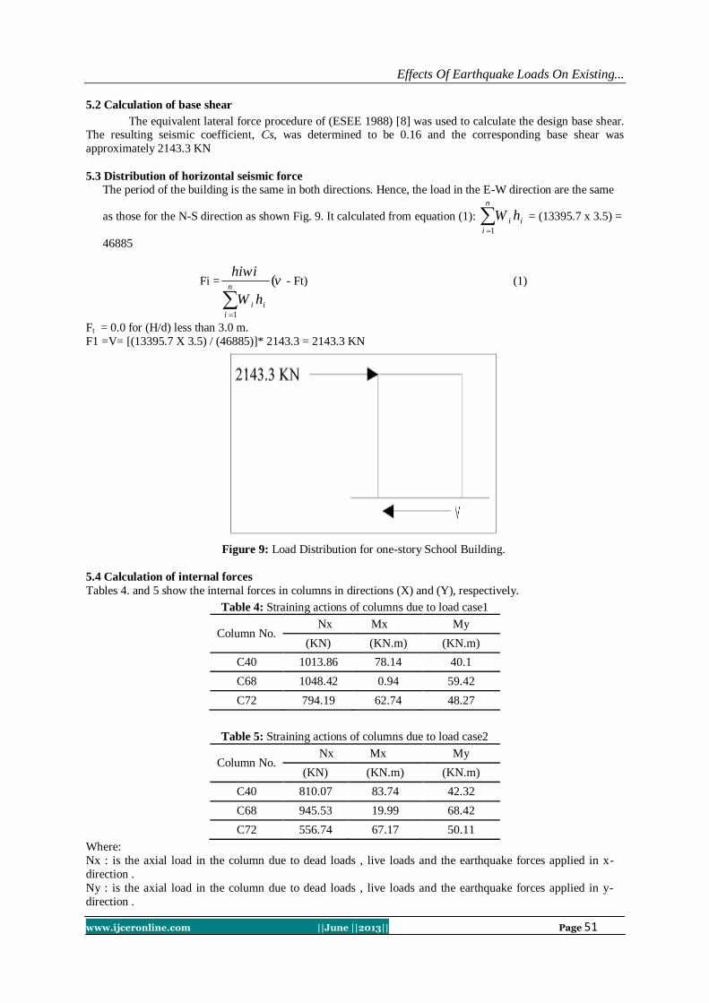
5.3 Distribution of horizontal seismic force
The period of the building is the same in both directions. Hence, the load in the E-W direction are the same
as those for the N-S direction as shown Fig. 9. It calculated from equation (1): 1
n
i i
i
W h
= (13395.7 x 3.5) =
46885
Fi =
1
(n
i i
i
hiwiv
W h
- Ft) (1)
Ft = 0.0 for (H/d) less than 3.0 m.
F1 =V= [(13395.7 X 3.5) / (46885)]* 2143.3 = 2143.3 KN
Figure 9: Load Distribution for one-story School Building.
5.4 Calculation of internal forces
Tables 4. and 5 show the internal forces in columns in directions (X) and (Y), respectively.
Table 4: Straining actions of columns due to load case1
Column No. Nx Mx My
(KN) (KN.m) (KN.m)
C40 1013.86 78.14 40.1
C68 1048.42 0.94 59.42
C72 794.19 62.74 48.27
Table 5: Straining actions of columns due to load case2
Column No. Nx Mx My
(KN) (KN.m) (KN.m)
C40 810.07 83.74 42.32
C68 945.53 19.99 68.42
C72 556.74 67.17 50.11
Where:
Nx : is the axial load in the column due to dead loads , live loads and the earthquake forces applied in x-
direction .
Ny : is the axial load in the column due to dead loads , live loads and the earthquake forces applied in y-
direction .
Effects Of Earthquake Loads On Existing...
www.ijceronline.com ||June ||2013|| Page 52
Mx : is the bending moment at the column due to the earthquake forces applied in x- direction .
My : is the bending moment at the column due to the earthquake forces applied in y- direction .
5.5 Design of the structural elements
The reinforced concrete sections are designed according to the BSI 8110 [4] using the limit state design
method [5] .
5.6 Results of columns' design. (i) Earthquake force in Direction x-x
Table 6: Design of columns after adding seismic loads-direction (x)
Column No. Original design Including seismic loads
Dimensions Reinforcement Dimensions Reinforcement
C40 300 X 450 8 Φ 16 300 X 350 8 Φ 16
C68 300 X 450 8 Φ 16 300 X 300 6 Φ 16
C72 300 X 450 8 Φ 16 300 X 350 8 Φ 16
(ii)Earthquake in Direction y-y
Table 7. Shows the design of columns after adding seismic loads.
Table 7: Design of columns after adding seismic loads-direction (y)
Column No. Original design Including seismic loads
Dimensions Reinforcement Dimensions Reinforcement
C40 300 X 450 8 Φ 16 300 X 350 8 Φ 16
C68 300 X 450 8 Φ 16 300 X 350 8 Φ 16
C72 300 X 450 8 Φ 16 300 X 350 8 Φ 16
(b) Design of beams
As for the beams the internal forces due to gravity loads have been calculated first .Then the BSI [4] , has been
used to check the existing design .It has been found that the existing design is adequate.
5.7 Summary of the first case study
The results of this study show that: 1-All columns and beams are safe to withstand gravity loads.
2-The existing school building studied in this case doesn’t need strengthening.
VI . EVALUATION OF SEISMIC PERFORMANCE OF SECOND CASE STUDY The same procedure as that used in the first case study has been used .The following results have
been obtained:
6.1 Calculation of base shear
The equivalent lateral force procedure of (ESEE 1988) was used to calculate the design base shear. The resulting seismic coefficient, Cs, was determined to be 0.16 and the corresponding base shear was
approximately 4073 KN.
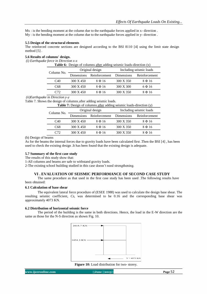
6.2 Distribution of horizontal seismic force
The period of the building is the same in both directions. Hence, the load in the E-W direction are the
same as those for the N-S direction as shown Fig. 10.
Figure 10: Load distribution for two- storey.
Effects Of Earthquake Loads On Existing...
www.ijceronline.com ||June ||2013|| Page 53
6.3 Results of columns' design 1- Earthquake in Direction x-x
Table 8. Shows the design of columns after adding seismic loads.
Table 8 : Design of columns after adding seismic loads-direction (x)
Column No. Original design Including seismic loads
Dimensions Reinforcement Dimensions Reinforcement
C40 300 X 450 8 Φ 16 300 X 550 12 Φ 16
C68 300 X 450 8 Φ 16 300 X 550 12 Φ 16
C72 300 X 450 8 Φ 16 300 X 450 10 Φ 16
2- Earthquake in Direction y-y
Table 9. Shows the Design of columns after adding seismic loads.
Table 9: Design of columns after adding seismic loads-direction (y)
Column No. Original design Including seismic loads
Dimensions Reinforcement Dimensions Reinforcement
C40 300 X 450 8 Φ 16 300 X 550 12 Φ 16
C68 300 X 450 8 Φ 16 300 X 550 12 Φ 16
C72 300 X 450 8 Φ 16 300 X 450 10 Φ 16
6.4 Results of beams' design
As for the beams the internal forces due to gravity loads have been calculated first.Then the BSI [4],
has been used to check the existing design. It has been found that the existing design is adequate to resist gravity
loads only. In general, it has been found that all beams in this model are safe under static loads, whereas few
columns are unsafe. From this fact, school buildings in Sudan should be strengthened.
VII. PROPOSED METHOD FOR STRENGTHENING EXISTING RC SCHOOL BODINGS
IN SUDAN Seismic retrofitting is a modification of the structural and / or non-structural components in a building
that aims to improve the building's performance in future earthquakes. Adding structural walls is one of the most
common structure-level retrofitting methods to strengthen existing structures. This approach is effective for
controlling global lateral drifts and for reducing damage in frame members. In this paper the seismic retrofitting
of existing reinforced concrete schools by means of steel shear panels is examined.
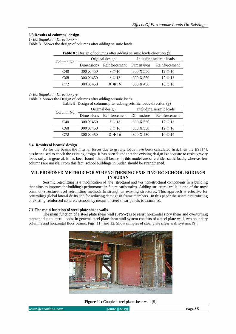
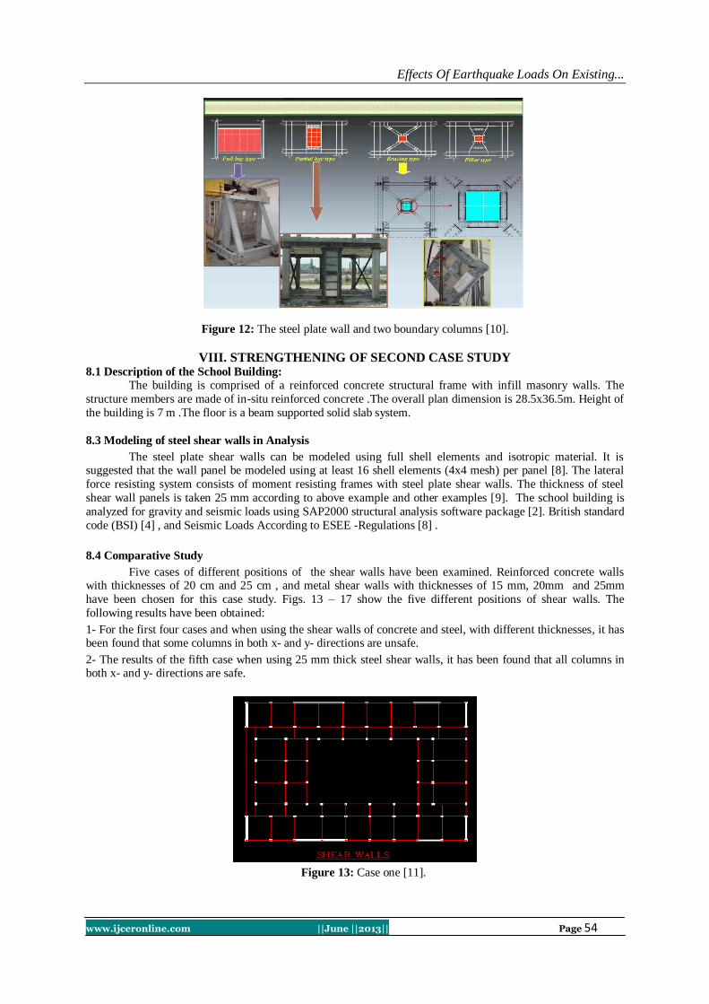
7.1 The main function of steel plate shear walls The main function of a steel plate shear wall (SPSW) is to resist horizontal story shear and overturning
moment due to lateral loads. In general, steel plate shear wall system consists of a steel plate wall, two boundary
columns and horizontal floor beams, Figs. 11 , and 12. Show samples of steel plate shear wall systems [9].
Figure 11: Coupled steel plate shear wall [9].
Effects Of Earthquake Loads On Existing...
www.ijceronline.com ||June ||2013|| Page 54
Figure 12: The steel plate wall and two boundary columns [10].
VIII. STRENGTHENING OF SECOND CASE STUDY 8.1 Description of the School Building:
The building is comprised of a reinforced concrete structural frame with infill masonry walls. The
structure members are made of in-situ reinforced concrete .The overall plan dimension is 28.5x36.5m. Height of
the building is 7 m .The floor is a beam supported solid slab system.
8.3 Modeling of steel shear walls in Analysis
The steel plate shear walls can be modeled using full shell elements and isotropic material. It is suggested that the wall panel be modeled using at least 16 shell elements (4x4 mesh) per panel [8]. The lateral
force resisting system consists of moment resisting frames with steel plate shear walls. The thickness of steel
shear wall panels is taken 25 mm according to above example and other examples [9]. The school building is
analyzed for gravity and seismic loads using SAP2000 structural analysis software package [2]. British standard
code (BSI) [4] , and Seismic Loads According to ESEE -Regulations [8] .
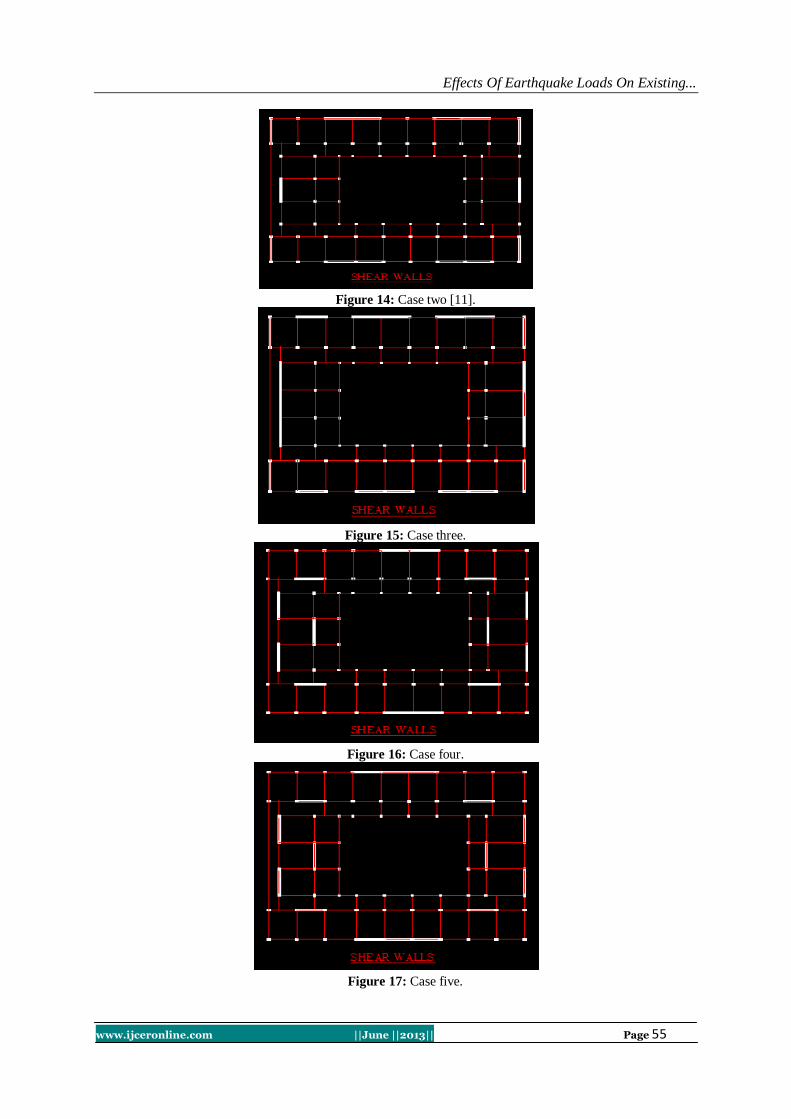
8.4 Comparative Study
Five cases of different positions of the shear walls have been examined. Reinforced concrete walls with thicknesses of 20 cm and 25 cm , and metal shear walls with thicknesses of 15 mm, 20mm and 25mm
have been chosen for this case study. Figs. 13 – 17 show the five different positions of shear walls. The
following results have been obtained:
1- For the first four cases and when using the shear walls of concrete and steel, with different thicknesses, it has been found that some columns in both x- and y- directions are unsafe.
2- The results of the fifth case when using 25 mm thick steel shear walls, it has been found that all columns in both x- and y- directions are safe.
Figure 13: Case one [11].
Effects Of Earthquake Loads On Existing...
www.ijceronline.com ||June ||2013|| Page 55
Figure 14: Case two [11].
Figure 15: Case three.
Figure 16: Case four.
Figure 17: Case five.
Effects Of Earthquake Loads On Existing...
www.ijceronline.com ||June ||2013|| Page 56
8.5 Design of some columns after retrofitting
The same procedure as that used in the design before retrofitting has been used. The following results
have been obtained:
8.6 Calculation of base shear
The equivalent lateral force procedure of (ESEE 1988) was used to calculate a design base shear. The
resulting seismic coefficient, Cs, was determined to be 0.16 and the corresponding base shear was approximately 2773 KN.
8.7 Comparison between original and retrofitted design
1-Earthquake forces in Direction x-x
Table 10. Shows the design results of some columns after retrofitting due to earthquake forces in direction x-x
Table 10: Design results of some columns after retrofitting- direction (x)
Column No. Original design Design including seismic loads After retrofitting
Dimensions Reinforcement Dimensions Reinforcement Dimensions Reinforcement
C40 300 X 450 8 Φ 16 300 X 550 12 Φ 16 300 X 300 6 Φ 16
C68 300 X 450 8 Φ 16 300 X 500 10 Φ 16 300 X 300 6 Φ 16
C72 300 X 450 8 Φ 16 300 X 500 10 Φ 16 300 X 400 8 Φ 16
2- Earthquake in Direction y-y
Table 11. Shows the design results of some columns after retrofitting due to earthquake forces in direction y.
Table 11: Design results of some columns after retrofitting -direction (y)
Column No. Original design Dseign including seismic loads After retrofitting
Dimensions Reinforcement Dimensions Reinforcement Dimensions Reinforcement
C40 300 X 450 8 Φ 16 300 X 550 12 Φ 16 300 X 400 6 Φ 16
C68 300 X 450 8 Φ 16 300 X 500 10 Φ 16 300 X 300 6 Φ 16
C72 300 X 450 8 Φ 16 300 X 500 10 Φ 16 300 X 300 8 Φ 16
XI. CONCLUSIONS
Shear metal panels actually represent a very suitable strategy to reduce the seismic vulnerability of
exiting RC school buildings in Sudan. From the results obtained, it can be concluded that:
1-Current design of school buildings in Sudan does not consider earthquake loads.
2-A proposed methodology has been presented for evaluation of seismic resistance of existing school buildings
in Sudan.
3-It has been found that the current design of school buildings in the Sudan is not safe for the current seismicity of the Sudan.
4-A strengthening technique for existing school buildings has been presented.
REFERENCES [1] Abdalla, Jamal A.; Mohamedzein, Yahia E-A., and Abdel Wahab, Abubakr. (1997). Seismic hazard assessment and zoning of
Sudan. Sudan Engineering Society Journal, Volume 44, No. 35, pp. 34-51.
[2] Computers and Structures. SAP2000: Three Dimensional Static and Dynamic Finite Element Analysis and Design of Structures,
Computers and Structures Inc., Berkeley, California, U.S.A. 2001.
[3] A .Y. Shehata, Information Systems Application on Reinforced Concrete Columns., M.Sc. Thesis, Faculty of Engineering,
Department of Structural Engineering, Cairo University, Giza, Egypt, 1999.
[4] BS 8110. The Structural Use of Concrete, British Standard Institution, London. 1997.
[5] Mosley, W. H. and Bungey, J. H. ,Reinforced Concrete Design (BS 8110:Part 1, 2nd Ed. Macmillan , London. 1997).
[6] Sobaih, M. E ;Hassaballa, A. E , & Ismaeil, M. A. ,Assessment of Seismic Performance and Strengthening of Existing School
Buildings in the Sudan, International Journal of Engineering Research &Technology (IJERT),ISSN:2278-0181, 2(6), 2013.
[7] A .A. Eissa, Towards a Sudanese Code of Practice for Earthquake Design., M.Sc. Thesis., Faculty of Engineering, Department of
Structural Engineering, Khartoum University, Khartoum, Sudan. 2002.
[8] Egyptian Society for Earthquake Engineering (ESEE) ,Regulations for Earthquake-Resistance Design of Buildings in
Egypt.,Cairo ,Egypt.,(1988).
[9] Abolhassan, P.E. ,Seismic Behaviour and Design of Steel Shear Walls.(ASI, Steel TIPS, First Print, California,2001).
[10] Astaneh-Asl, A., Steel Plate Shear Walls, Proceedings, U.S.-Japan Partnership for Advanced Steel Structures, U.S.-Japan
Workshop on Seismic Fracture issues in Steel Structure, San Francisco, February 2000.
[11] Ismaeil, M. A., and Sobaih, M.E, A Proposed Methodology for Seismic Evaluation and Strengthening of Existing School
Buildings in The Sudan., 15th WCEE, Portugal, September, 2012. Paper No.0 571.